Embed Size (px)
Citation preview
INSTALLATION AND MAINTENANCE INSTRUCTIONS
FIGHTER 1220MOS GB 0429-1 011676FIGHTER 1220
LEK
Fighter 1220
R


For the Installer
Contents 1
FIGHTER 1220
For Home Owners
General information for the installerTransport and storage ............................................9Installation ..............................................................9Guideline values for collectors ................................9Inspection of the installation ....................................9Electric boiler mode ................................................ 9Brine pump.............................................................. 9Electric anode (Enamel).......................................... 9
Pipe connectionsGeneral ................................................................ 10Pipe connection (collector) .................................. 10Pipe connection (heating medium) ...................... 10Pipe connections (water heater) .......................... 11Ventilation recovery .............................................. 11Free cooling ........................................................ 11Pump capacity diagrams, heating medium side .. 12
Electrical connectionsConnection .......................................................... 13Resetting the temperature limiter .......................... 13Tariff connection.................................................... 14Max hot water temperature .................................. 15Max phase current ................................................ 15Centralised load control and load monitor ............ 16External contacts .................................................. 17Connecting an outside temperature sensor ........ 18Alarm/alarm outputs .............................................. 18
Commissioning and adjustingPreparations ........................................................ 19Filling and venting the collector system .............. 19Filling the heating medium system ...................... 19Soft-start relay ...................................................... 19Starting and checking .......................................... 20Readjustment, heating medium side .................... 20Readjustments, brine side .................................... 20Emptying the water heater .................................. 20
Setting the automatic heating controlsystem
Setting with diagrams............................................ 21Heating curve offset -2 ........................................ 21Heating curve offset 0 .......................................... 21Heating curve offset +2 ........................................ 21
ControlGeneral ................................................................ 22Changing parameters............................................ 23Key lock ................................................................ 23Quick movement .................................................. 23Menu tree .............................................................. 24Main menus .......................................................... 27Hot water temperature .......................................... 28Supply temperature .............................................. 29Outside temperature ............................................ 31Brine flow/return .................................................... 31Clock .................................................................... 32Other settings........................................................ 34
Service menusSettings additional heat ........................................ 36Operating settings ................................................ 36Quick start ..............................................................39TEST Force driven operation ................................ 39Alarm log .............................................................. 39
Dealing with malfunctionsAlarm indications on the display .......................... 40Low hot water temperature or no hot water ........ 42Low room temperature ........................................ 42High room temperature ........................................ 42Helping the circulation pump to start .................... 43Draining, heat medium side ................................ 43Draining, brine side .............................................. 43
DimensionsDimensions and setting-out coordinates .............. 44
List of componentsList of components ................................................ 45
Component positionsComponent locations ............................................ 46
Wiring diagram 3 x 400 V + NElectrical circuit diagram ...................................... 48
Technical specificationsTechnical specifications ........................................ 52
Enclosed kitEnclosed kit .......................................................... 53
AccessoriesAccessories .......................................................... 54
GeneralConcise product description .................................. 2Setting table .......................................................... 2
System descriptionPrinciple of operation ............................................ 3
Front panelLayout .................................................................. 4Explanation .......................................................... 4
Room temperatureAutomatic heating control system ........................ 6Default setting ...................................................... 6Changing the room temperature .......................... 6Basic values for the automatic heating
control system .................................................... 7Heat production...................................................... 8Domestic hot water ................................................ 8Standby mode ........................................................ 8
General
FIGHTER 1220
For Home Owners
2
In order to get the ultimate benefit from your heat pump FIGHTER 1220 you should read throughthe For Home Owners section in this Installation and Maintenance Instruction.
FIGHTER 1220 is a heat pump central for the production of heating and domestic hot water in detachedand terrace houses. The ground, rock or lakes can be used as the heat source.
FIGHTER 1220 is a Swedish made quality product offering a long life span and safe operation.
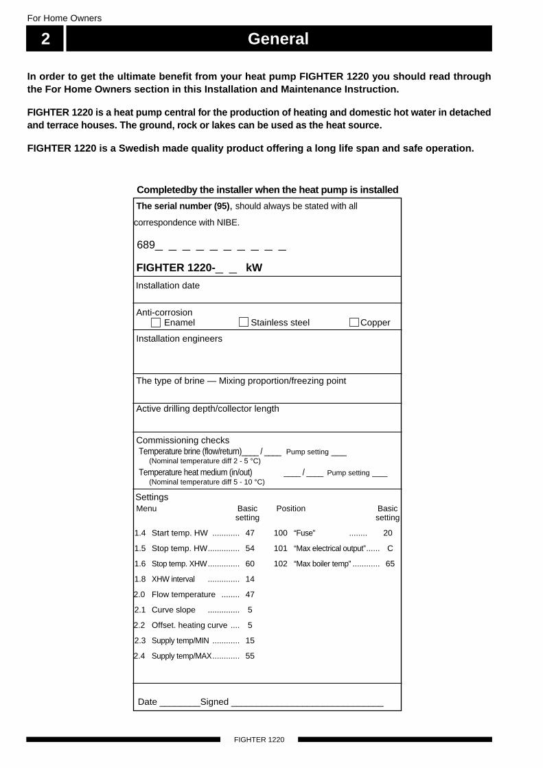
Completedby the installer when the heat pump is installed
Installation date
The serial number (95), should always be stated with all
correspondence with NIBE.
689_ _ _ _ _ _ _ _ _ _
FIGHTER 1220-_ _ kW
Installation engineers
Anti-corrosionEnamel Stainless steel Copper
The type of brine — Mixing proportion/freezing point
Active drilling depth/collector length
Commissioning checksTemperature brine (flow/return)____ / ____ Pump setting ___
(Nominal temperature diff 2 - 5 °C)
Temperature heat medium (in/out) ____ / ____ Pump setting ___(Nominal temperature diff 5 - 10 °C)
Settings
Date ________Signed ______________________________
Menu Basicsetting
1.4 Start temp. HW ............ 47
1.5 Stop temp. HW.............. 54
1.6 Stop temp. XHW.............. 60
1.8 XHW interval .............. 14
2.0 Flow temperature ........ 47
2.1 Curve slope .............. 5
2.2 Offset. heating curve .... 5
2.3 Supply temp/MIN ............ 15
2.4 Supply temp/MAX............ 55
Position Basicsetting
100 “Fuse” ........ 20
101 “Max electrical output”...... C
102 “Max boiler temp” ............ 65
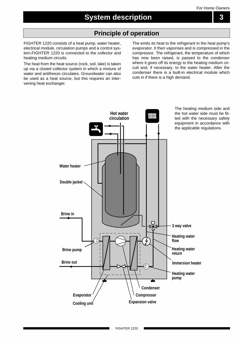
FIGHTER 1220 consists of a heat pump, water heater,electrical module, circulation pumps and a control sys-tem.FIGHTER 1220 is connected to the collector andheating medium circuits.
The heat from the heat source (rock, soil, lake) is takenup via a closed collector system in which a mixture ofwater and antifreeze circulates. Groundwater can alsobe used as a heat source, but this requires an inter-vening heat exchanger.
The emits its heat to the refrigerant in the heat pump’sevaporator. It then vaporises and is compressed in thecompressor. The refrigerant, the temperature of whichhas now been raised, is passed to the condenserwhere it gives off its energy to the heating medium cir-cuit and, if necessary, to the water heater. After thecondenser there is a built-in electrical module whichcuts in if there is a high demand.
System description 3For Home Owners
FIGHTER 1220
Principle of operation
The heating medium side andthe hot water side must be fit-ted with the necessary safetyequipment in accordance withthe applicable regulations.
Hot watercirculation
Heating waterpump
Immersion heater
3 way valve
Heating waterflow
Heating waterreturn
Evaporator
Brine pump
Compressor
Condenser
Expansion valveCooling unit
Double jacket
Brine in
Brine out
Water heater
Front panel
FIGHTER 1220
For Home Owners
4
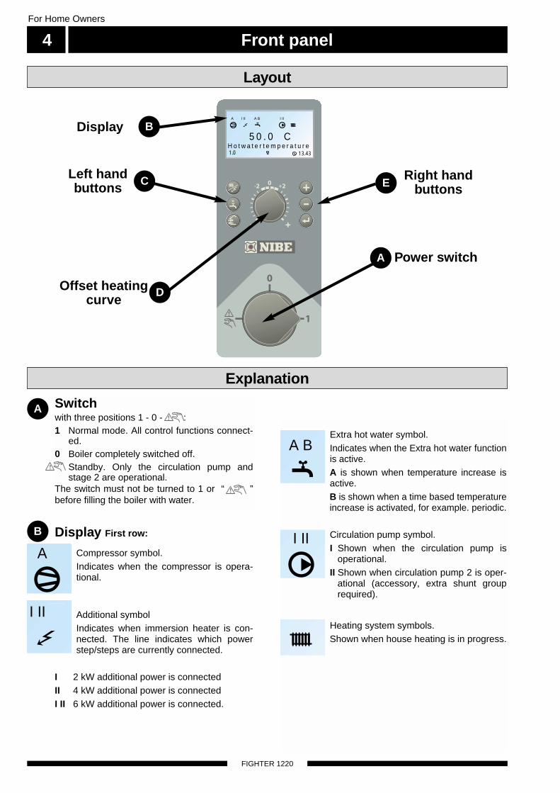
Switchwith three positions 1 - 0 - :1 Normal mode. All control functions connect-
ed. 0 Boiler completely switched off.
Standby. Only the circulation pump andstage 2 are operational.
The switch must not be turned to 1 or “ ”before filling the boiler with water.
DisplayA BI II III I II
5 0 . 0 CH o t w a t e r t e m p e r a t u r e
13.431.0
A
Power switch
Left handbuttons
Offset heatingcurve
Display First row:
Compressor symbol.Indicates when the compressor is opera-tional.
Additional symbolIndicates when immersion heater is con-nected. The line indicates which powerstep/steps are currently connected.
I 2 kW additional power is connectedII 4 kW additional power is connectedI II 6 kW additional power is connected.
Layout
B
A
C
D
Right handbuttons
Extra hot water symbol.Indicates when the Extra hot water functionis active. A is shown when temperature increase isactive.B is shown when a time based temperatureincrease is activated, for example. periodic.
Circulation pump symbol.I Shown when the circulation pump is
operational.II Shown when circulation pump 2 is oper-
ational (accessory, extra shunt grouprequired).
Heating system symbols.Shown when house heating is in progress.
E
B
Explanation
A
I II III
A B
I IIA
Front panel 5For Home Owners
FIGHTER 1220
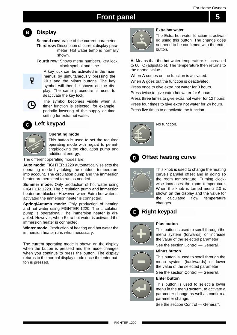
DisplaySecond row: Value of the current parameter.Third row: Description of current display para-
meter. Hot water temp is normallyshown.
Fourth row: Shows menu numbers, key lock,clock symbol and time
Left keypad
Right keypad
Offset heating curveD
C
E
Operating modeThis button is used to set the requiredoperating mode with regard to permit-ting/blocking the circulation pump andadditional energy.
The different operating modes are:Auto mode: FIGHTER 1220 automatically selects theoperating mode by taking the outdoor temperatureinto account. The circulation pump and the immersionheater are permitted to run as needed.Summer mode: Only production of hot water usingFIGHTER 1220. The circulation pump and immersionheater are blocked. However, when Extra hot water isactivated the immersion heater is connected.Spring/Autumn mode: Only production of heatingand hot water using FIGHTER 1220. The circulationpump is operational. The immersion heater is dis-abled. However, when Extra hot water is activated theimmersion heater is connected.Winter mode: Production of heating and hot water theimmersion heater runs when necessary.
The current operating mode is shown on the displaywhen the button is pressed and the mode changeswhen you continue to press the button. The displayreturns to the normal display mode once the enter but-ton is pressed.
Extra hot water The Extra hot water function is activat-ed using this button. The change doesnot need to be confirmed with the enterbutton.
A: Means that the hot water temperature is increasedto 60 °C (adjustable). The temperature then returns tothe normal value.When A comes on the function is activated.When A goes out the function is deactivated.Press once to give extra hot water for 3 hours.Press twice to give extra hot water for 6 hours.Press three times to give extra hot water for 12 hours.Press four times to give extra hot water for 24 hours.Press five times to deactivate the function.
Plus buttonThis button is used to scroll through themenu system (forwards) or increase the value of the selected parameter.
See the section Control — General.
Minus buttonThis button is used to scroll through themenu system (backwards) or lower the value of the selected parameter.
See the section Control — General.
Enter buttonThis button is used to select a lowermenu in the menu system, to activate aparameter change as well as confirm aparameter change.
See the section Control — General”.
This knob is used to change the heatingcurve's parallel offset and in doing sothe room temperature. Turning clock-wise increases the room temperature.When the knob is turned menu 2.0 isshown on the display and the value forthe calculated flow temperaturechanges.
No function.
B
A key lock can be activated in the mainmenus by simultaneously pressing thePlus and the Minus buttons. The keysymbol will then be shown on the dis-play. The same procedure is used todeactivate the key lock.
The symbol becomes visible when atimer function is selected, for example,periodic lowering of the supply or timesetting for extra hot water.
1
Room temperature
FIGHTER 1220
For Home Owners
6
Automatic heating control systemThe indoor temperature depends on several factors.Sunlight and heat emissions from people and house-hold machines are normally sufficient to keep thehouse warm during the warmer parts of the year.When it gets colder outside, the heating system mustbe started. The colder it is outside, the warmer radia-tors and floor heating system must be. With theFIGHTER 1220, this adjustment is done automaticallyby a control computer. Before the computer can dothis, some basic settings are required.The heat pump is controlled by built-in sensors for flowand return heat brine temperatures (collector). Brinereturn temperatures can, if so required, be limited to aminimum (e.g. for ground water systems).
Heat production is usually controlled using the floatingcondensing principle. This means that the temperaturelevel needed for heating at a given outside tempera-ture is produced on the basis of values taken fromsensors for outside temperature and flow temperature.As an option, room sensors can also be used to com-pensate for deviations in room temperature, see menu2.5 Compensation outer. However, the correct basicsettings must be made on the boiler first, see the sec-tion Room temperature — Basic setting.
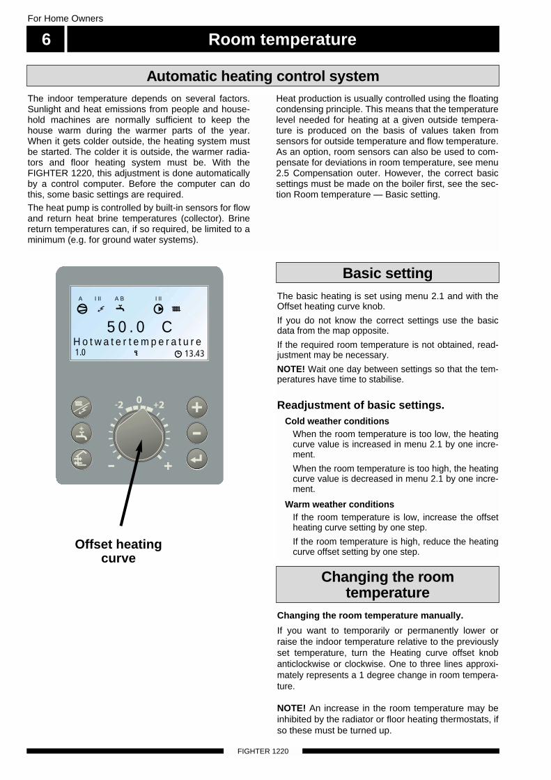
The basic heating is set using menu 2.1 and with theOffset heating curve knob.
If you do not know the correct settings use the basicdata from the map opposite.
If the required room temperature is not obtained, read-justment may be necessary.
NOTE! Wait one day between settings so that the tem-peratures have time to stabilise.
Readjustment of basic settings.Cold weather conditions
When the room temperature is too low, the heatingcurve value is increased in menu 2.1 by one incre-ment.
When the room temperature is too high, the heatingcurve value is decreased in menu 2.1 by one incre-ment.
Warm weather conditionsIf the room temperature is low, increase the offsetheating curve setting by one step.
If the room temperature is high, reduce the heatingcurve offset setting by one step.
Changing the room temperature manually.
If you want to temporarily or permanently lower orraise the indoor temperature relative to the previouslyset temperature, turn the Heating curve offset knobanticlockwise or clockwise. One to three lines approxi-mately represents a 1 degree change in room tempera-ture.
NOTE! An increase in the room temperature may beinhibited by the radiator or floor heating thermostats, ifso these must be turned up.
Basic setting
Changing the room temperature
A BI II III I II
5 0 . 0 CH o t w a t e r t e m p e r a t u r e
13.431.0
A
Offset heatingcurve
Room temperature 7For Home Owners
FIGHTER 1220
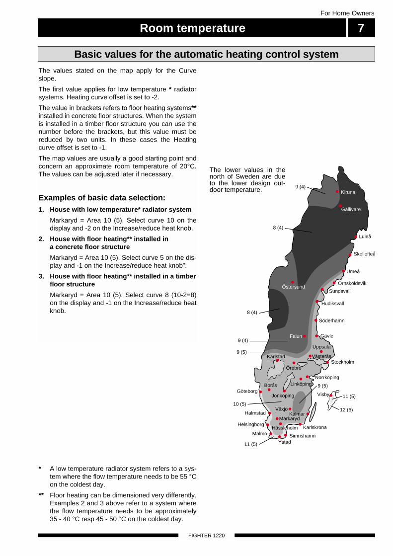
The values stated on the map apply for the Curveslope.
The first value applies for low temperature * radiatorsystems. Heating curve offset is set to -2.
The value in brackets refers to floor heating systems**installed in concrete floor structures. When the systemis installed in a timber floor structure you can use thenumber before the brackets, but this value must bereduced by two units. In these cases the Heatingcurve offset is set to -1.
The map values are usually a good starting point andconcern an approximate room temperature of 20°C.The values can be adjusted later if necessary.
Examples of basic data selection:1. House with low temperature* radiator system
Markaryd = Area 10 (5). Select curve 10 on thedisplay and -2 on the Increase/reduce heat knob.
2. House with floor heating** installed in a concrete floor structure
Markaryd = Area 10 (5). Select curve 5 on the dis-play and -1 on the Increase/reduce heat knob”.
3. House with floor heating** installed in a timberfloor structure
Markaryd = Area 10 (5). Select curve 8 (10-2=8)on the display and -1 on the Increase/reduce heatknob.
* A low temperature radiator system refers to a sys-tem where the flow temperature needs to be 55 °Con the coldest day.
** Floor heating can be dimensioned very differently.Examples 2 and 3 above refer to a system wherethe flow temperature needs to be approximately35 - 40 °C resp 45 - 50 °C on the coldest day.
Basic values for the automatic heating control system
The lower values in thenorth of Sweden are dueto the lower design out-door temperature.
Skellefteå
Umeå
Örnsköldsvik
Sundsvall
Hudiksvall
Gävle
Stockholm
Visby
Luleå
JönköpingGöteborg
Borås
HalmstadMarkaryd
Helsingborg
Malmö
VäxjöKalmar
LinköpingNorrköping
Karlskrona
YstadSimrishamn
Örebro
Karlstad
Hässleholm
Uppsala
Västerås
Söderhamn
11 (5)
10 (5)
9 (5)
9 (4)
8 (4)
8 (4)
9 (4)
Gällivare
Östersund
Kiruna
Falun
9 (5)
11 (5)
12 (6)
Room temperature
FIGHTER 1220
For Home Owners
8
When there is a demand for hot water, the heat pumpgives this priority and devotes its entire output towater heating. No room heat is produced in thismode. Maximum time for hot water charging isadjustable using menu 1.3. Heating is then producedfor the remainder of the time, which is adjustable frommenu 1.2, before any further hot water charging cantake place.
If the electrical module is connected for heat produc-tion before hot water charging, one stage remainsoperative during hot water operation. Hot watercharging starts when the hot water sensor has fallento the set start temperature (25 — 50 °C), adjustableon menu 1.4. Hot water charging stops when thewater temperature has reached (30 — 58 °C),adjustable on menu 1.5. Charging is also possiblewhen the heat pump has reached its stop level forheating mode at the same time as less than 2 °Cremains to the hot water start. The purpose of this isto minimise the number of starts.
NOTE! The indicated hot water temperature is mea-sured on the lower part of the water heater jacket.This means that it is not the exact temperature of thehot water. Usually the outgoing hot water is hotterthan the indicated temperature.
For occasional higher demand for hot water, the Extrahot water function can be used to raise the tempera-ture to about 70 °C for 3 —24 hours (press the Extrahot water button once). When the electrical module isconnected for extra hot water the compressor stops.The value is adjustable between 50 — 65 °C frommenu 1.7.
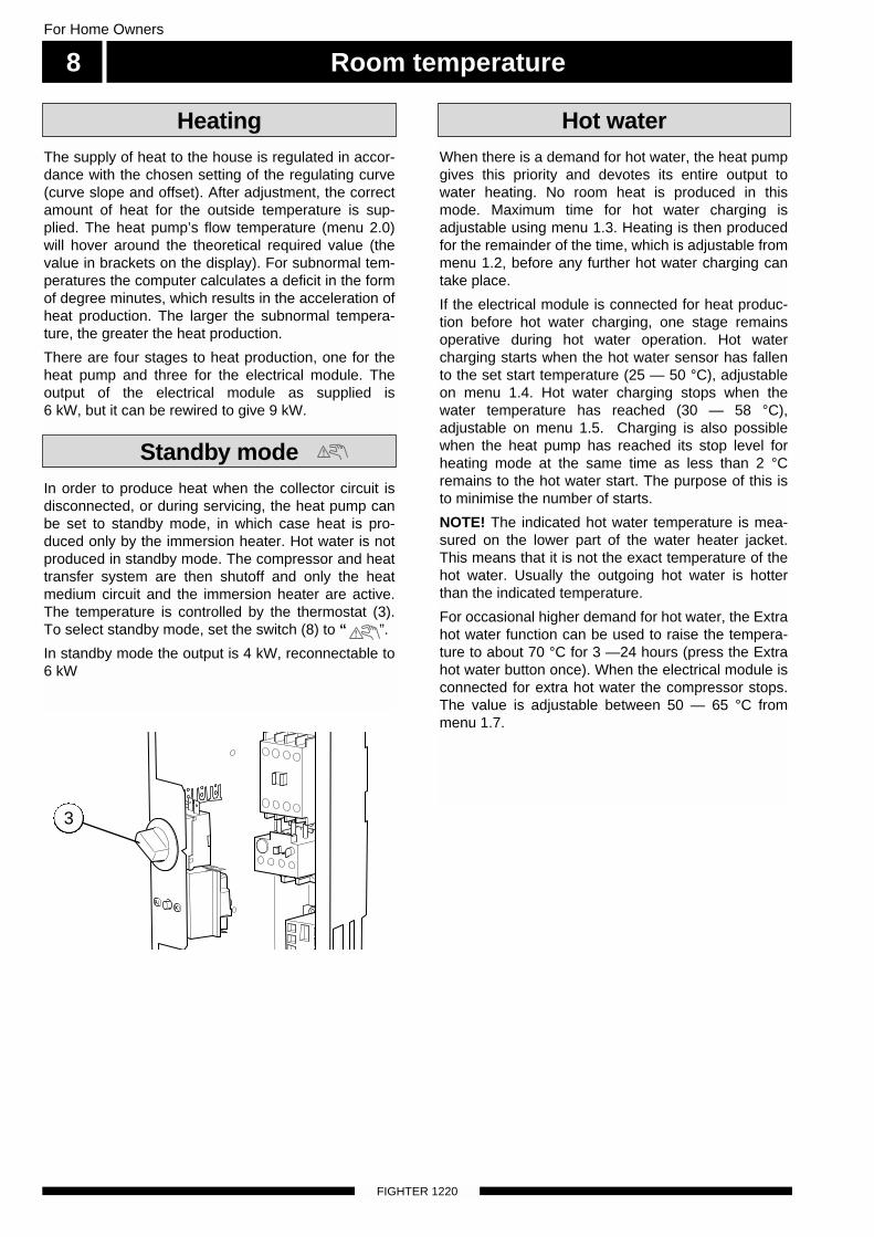
In order to produce heat when the collector circuit isdisconnected, or during servicing, the heat pump canbe set to standby mode, in which case heat is pro-duced only by the immersion heater. Hot water is notproduced in standby mode. The compressor and heat transfer system are then shutoff and only the heatmedium circuit and the immersion heater are active.The temperature is controlled by the thermostat (3).To select standby mode, set the switch (8) to “ ”.
In standby mode the output is 4 kW, reconnectable to6 kW
Hot water
Standby mode
The supply of heat to the house is regulated in accor-dance with the chosen setting of the regulating curve(curve slope and offset). After adjustment, the correctamount of heat for the outside temperature is sup-plied. The heat pump’s flow temperature (menu 2.0)will hover around the theoretical required value (thevalue in brackets on the display). For subnormal tem-peratures the computer calculates a deficit in the formof degree minutes, which results in the acceleration ofheat production. The larger the subnormal tempera-ture, the greater the heat production.
There are four stages to heat production, one for theheat pump and three for the electrical module. Theoutput of the electrical module as supplied is 6 kW, but it can be rewired to give 9 kW.
Heating
3
General information for the installer 9For the Installer
FIGHTER 1220
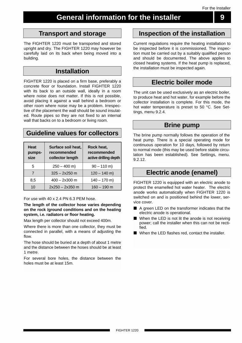
Current regulations require the heating installation tobe inspected before it is commissioned. The inspec-tion must be carried out by a suitably qualified personand should be documented. The above applies toclosed heating systems. If the heat pump is replaced,the installation must be inspected again.
FIGHTER 1220 is placed on a firm base, preferably aconcrete floor or foundation. Install FIGHTER 1220with its back to an outside wall, ideally in a roomwhere noise does not matter. If this is not possible,avoid placing it against a wall behind a bedroom orother room where noise may be a problem. Irrespec-tive of the placement the wall should be sound insulat-ed. Route pipes so they are not fixed to an internalwall that backs on to a bedroom or living room.
The FIGHTER 1220 must be transported and storedupright and dry. The FIGHTER 1220 may however becarefully laid on its back when being moved into abuilding.
Transport and storage
Installation
Inspection of the installation
The unit can be used exclusively as an electric boiler,to produce heat and hot water, for example before thecollector installation is complete. For this mode, thehot water temperature is preset to 50 °C. See Set-tings, menu 9.2.4.
The brine pump normally follows the operation of theheat pump. There is a special operating mode forcontinuous operation for 10 days, followed by returnto normal mode (this may be used before stable circu-lation has been established). See Settings, menu.9.2.12.
Electric boiler mode
FIGHTER 1220 is equipped with an electric anode toprotect the enamelled hot water heater. The electricanode works automatically when FIGHTER 1220 isswitched on and is positioned behind the lower, ser-vice cover.
■ A green LED on the transformer indicates that theelectric anode is operational.
■ When the LED is not lit the anode is not receivingpower; call the installer when this can not be recti-fied.
■ When the LED flashes red, contact the installer.
Electric anode (enamel)
Brine pump
10 2x250 – 2x350 m 160 – 190 m
7 325 – 2x250 m 120 – 140 m)
Heat Surface soil heat, Rock heat,pumps- recommended recommendedsize collector length active drilling depth
Guideline values for collectors
For use with 40 x 2.4 PN 6.3 PEM hose.
The length of the collector hose varies dependingon the rock /ground conditions and on the heatingsystem, i.e. radiators or floor heating.Max length per collector should not exceed 400m.
Where there is more than one collector, they must beconnected in parallel, with a means of adjusting theflow.
The hose should be buried at a depth of about 1 metreand the distance between the hoses should be at least1 metre.
For several bore holes, the distance between theholes must be at least 15m.
5 250 – 400 m) 90 – 110 m)
8,5 400 – 2x300 m 140 – 170 m)

Pipe connectionsFor the Installer
10
FIGHTER 1220
Factors to be taken into account when designing thecollector layout are geographical position, type ofrock/soil and cover factor of the heat pump. When installing the collector hose ensure it rises con-stantly towards the heat pump to avoid air pockets. Ifthis is not possible, install high points to vent the air.All collector pipes in heated rooms must be insulatedagainst condensation. The level vessel (NK) must beinstalled as the highest point in the collector systemand on the incoming pipe before the brine pump. Notethat condensation may drip from the level vessel.Position the vessel so that this does not harm otherequipment.As the temperature of the collector system can fallbelow 0 °C it must be protected against freezing downto -15 °C. One litre of ready mixed brine per meter ofcollector hose (applies when using PEM-hose 40 x2.4 PN 6.3) is used as a guide value when making thevolume calculation. Details of the antifreeze used must be shown on thelevel vessel.The collector circuit may be connected from the left orfrom the right. The lower side panels are swappedover to suit the chosen connection option. Theenclosed connecting pipes for the brine, are securedusing the clips in the punched tabs that are foldeddown on the side in question.Shut-off valves should be installed as close to theheat pump as possible. Fit the supplied particle filteron the incoming pipe.In the case of connection to an open groundwatersystem, an intermediate frost-protected circuit mustbe provided, because of the risk of dirt and freezing inthe evaporator. This requires an additional heatexchanger.
Pipe installation must be carried out in accordancewith current norms and directives. The heat pump canonly operate up to a return temperature of about 50 °Cand an outgoing temperature of about 60 °C from theheat pump. Since the FIGHTER 1220 is not fitted withshut-off valves, these must be fitted outside of theheat pump to make future servicing easier.
When installing FLM 30/40, pipes for the heat mediumand water heater and, if necessary hot water circula-tion, are routed backwards. The distance betweenFIGHTER 1220 and the wall ought to be 50 mm.
General
Pipe connections for the heat medium side are madeat the top. All required safety devices, shut-off valves(as close to the heat pump as possible), and particlefilter (supplied) are fitted.
When connecting to a system with thermostats on allradiators, a relief valve must be fitted, or some of thethermostats must be removed to ensure sufficientflow.
Pipe connections (heating medium)
Pipe connections (collector)
The water heater must be fitted with the necessaryvalve equipment.The heat pump should be supplemented with an elec-tric water heater if a bubble pool or other significantconsumer of hot water is installed.
Pipe connections (water heater)
NK Level vesselSF Particle filter
SÄV Safety valveAV Shut-off valveEXP Expansion vessel
SF
Brine In
EXP
P
SF
NK
AV
SÄV
Hot watercirculation
Brine Out
A BI II III I II I II
5 0 . 0 CVa r m v a t t e n t e m p . 1 . 0
A B A B
NOTE!The pipe work must be flushed
before the heat pump is connected,so that any contaminants do notdamage the component parts.
Pipe connections 11For the Installer
FIGHTER 1220
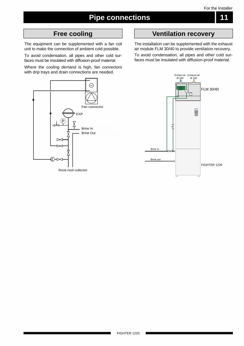
The installation can be supplemented with the exhaustair module FLM 30/40 to provide ventilation recovery.
To avoid condensation, all pipes and other cold sur-faces must be insulated with diffusion-proof material.
The equipment can be supplemented with a fan coilunit to make the connection of ambient cold possible.
To avoid condensation, all pipes and other cold sur-faces must be insulated with diffusion-proof material.
Where the cooling demand is high, fan convectorswith drip trays and drain connections are needed.
Free cooling Ventilation recovery
Fan convector
Inlet to heat pump
Outlet from heat pump
Rock-/soil collector
EXP
P
Brine InBrine Out
Brine in
Brine out
FIGHTER 1220
FLM 40
Exhaust airØ 160
Extract airØ 160
A BI II III I II I II
5 0 . 0 CVa r m v a t t e n t e m p . 1 . 0
A B A B
FLM 30/40
Pipe connections
FIGHTER 1220
For the Installer
12
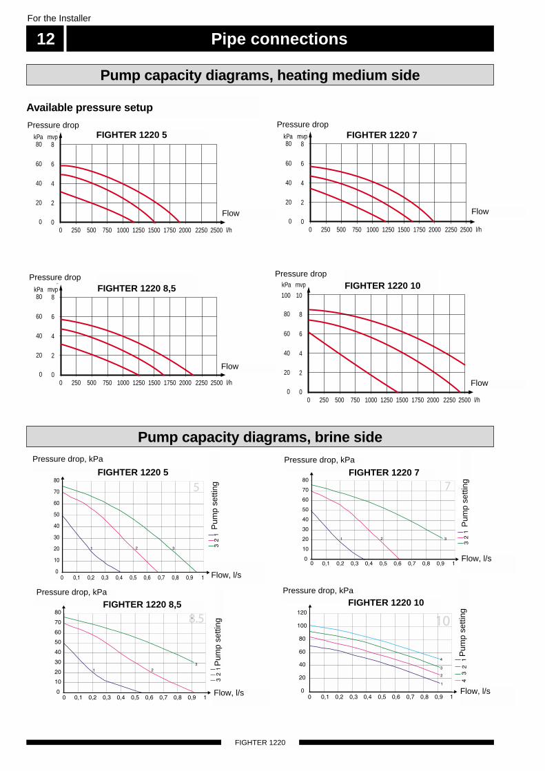
Pump capacity diagrams, heating medium side
Available pressure setup
Pump capacity diagrams, brine side
00
mvpkPa
250 500 7500
l/h1000
2
4
8
20
80
40
Tryckfall
Flöde
1250 1500 1750 250022502000
60 6
00
mvpkPa
250 500 7500
l/h1000
2
4
8
20
80
40
Tryckfall
Flöde
1250 1500 1750 250022502000
60 6
FIGHTER 1215 8,5
FIGHTER 1215 5
00
mvpkPa
250 500 7500
l/h1000
2
4
8
20
80
40
Tryckfall
Flöde
1250 1500 1750
60 6
250022502000
FIGHTER 1215 7
FIGHTER 1215 10
00
mvpkPa
250 500 7500
l/h1000
2
4
8
20
80
40
Tryckfall
Flöde
1250 1500 1750 250022502000
60 6
100 10
FIGHTER 1220 5 FIGHTER 1220 7
FIGHTER 1220 10FIGHTER 1220 8,5
Pressure drop
Flow
Flow
Flow, l/s
Flow, l/s
Flow, l/sFlow, l/s
Flow
Flow
Pressure drop
Pressure drop
Pressure drop, kPa
Pum
p se
tting
Pum
p se
tting
Pum
p se
tting
Pum
p se
tting
Pressure drop, kPa
Pressure drop, kPaPressure drop, kPa
Pressure drop
FIGHTER 1220 8,5
FIGHTER 1220 7FIGHTER 1220 5
FIGHTER 1220 10
Electrical connection 13For the Installer
FIGHTER 1220
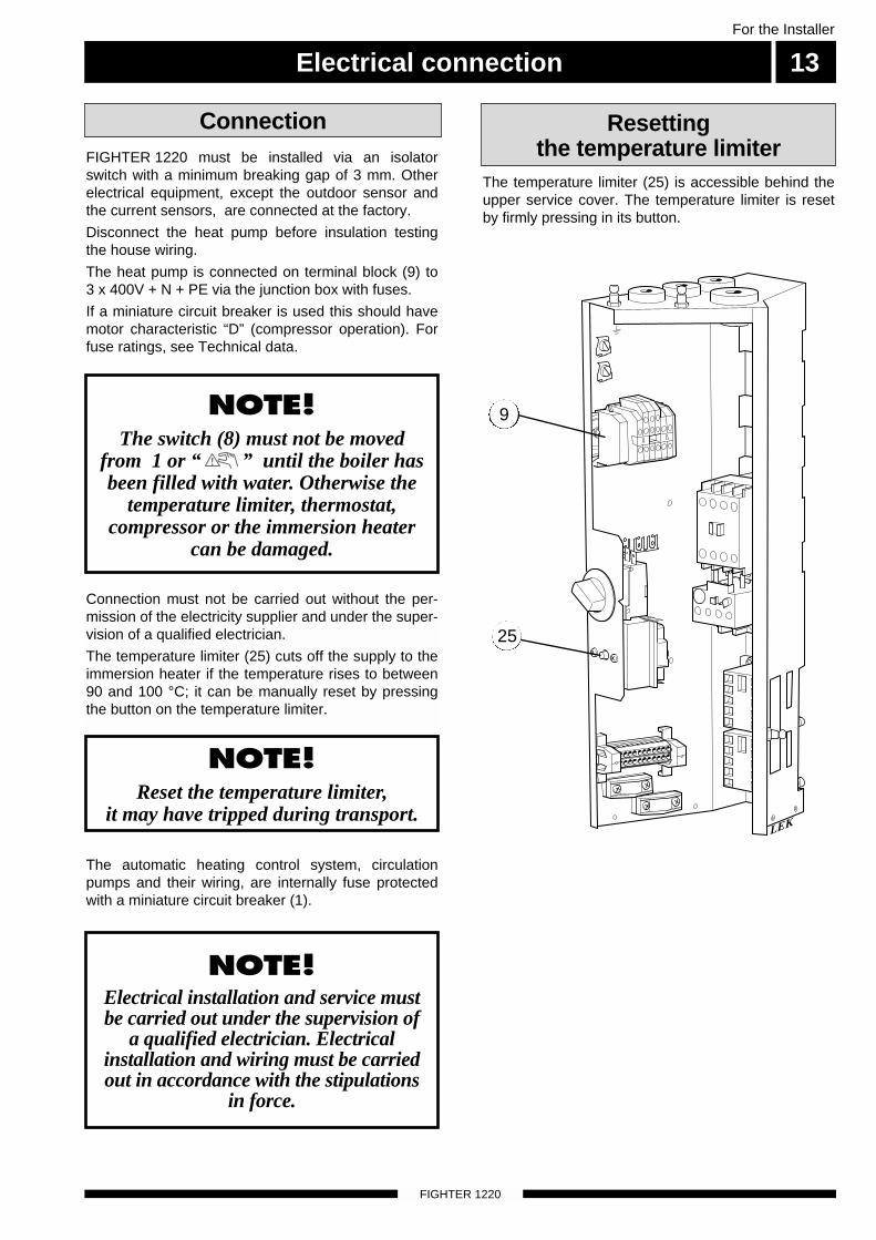
FIGHTER 1220 must be installed via an isolatorswitch with a minimum breaking gap of 3 mm. Otherelectrical equipment, except the outdoor sensor andthe current sensors, are connected at the factory.
Disconnect the heat pump before insulation testingthe house wiring.
The heat pump is connected on terminal block (9) to 3 x 400V + N + PE via the junction box with fuses.
If a miniature circuit breaker is used this should havemotor characteristic “D” (compressor operation). Forfuse ratings, see Technical data.
Connection
NOTE!Reset the temperature limiter,
it may have tripped during transport.
NOTE! The switch (8) must not be moved
from 1 or “ ” until the boiler hasbeen filled with water. Otherwise the
temperature limiter, thermostat,compressor or the immersion heater
can be damaged.
The automatic heating control system, circulationpumps and their wiring, are internally fuse protectedwith a miniature circuit breaker (1).
NOTE! Electrical installation and service mustbe carried out under the supervision of
a qualified electrician. Electricalinstallation and wiring must be carriedout in accordance with the stipulations
in force.
Connection must not be carried out without the per-mission of the electricity supplier and under the super-vision of a qualified electrician.
The temperature limiter (25) cuts off the supply to theimmersion heater if the temperature rises to between90 and 100 °C; it can be manually reset by pressingthe button on the temperature limiter.
The temperature limiter (25) is accessible behind theupper service cover. The temperature limiter is resetby firmly pressing in its button.
Resetting the temperature limiter
9
LEK
25
Electrical connection
FIGHTER 1220
For the Installer
14
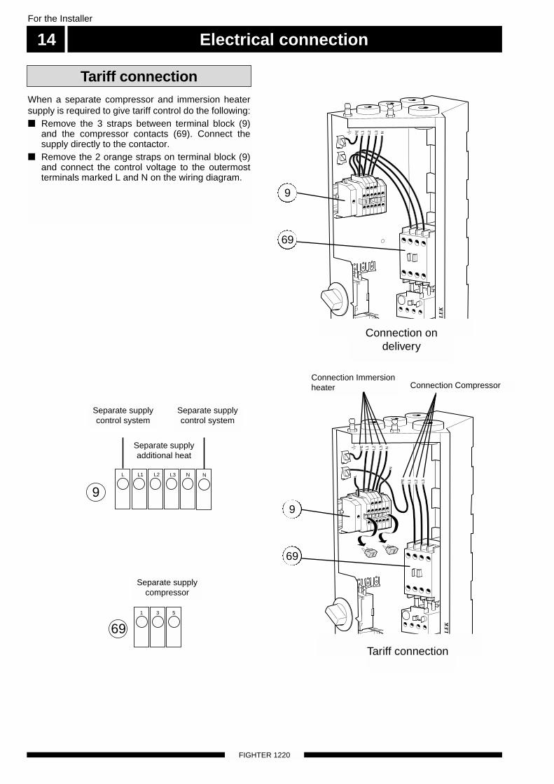
When a separate compressor and immersion heatersupply is required to give tariff control do the following: ■ Remove the 3 straps between terminal block (9)
and the compressor contacts (69). Connect thesupply directly to the contactor.
■ Remove the 2 orange straps on terminal block (9)and connect the control voltage to the outermostterminals marked L and N on the wiring diagram.
LE
K
PE L2 L3 NL1
PE
L1 L2 L3
PE L2 L3 N
L
L1
N
LE
K
Tariff connection
Tariff connection
Connection ondelivery
9
69
9
69
L L1 L2 L3 N N
9
1 3 5
69
Separate supplycontrol system
Separate supplyadditional heat
Separate supplycontrol system
Separate supplycompressor
Connection Immersionheater Connection Compressor
Electrical connection 15For the Installer
FIGHTER 1220
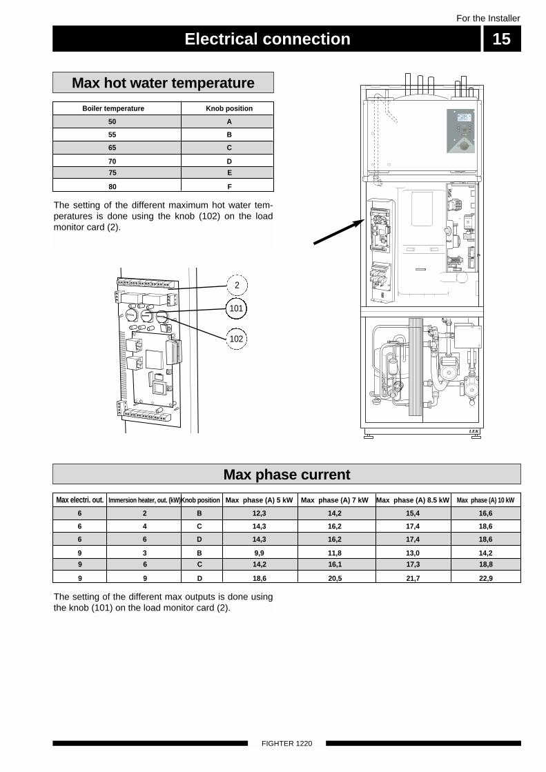
Max phase current
The setting of the different max outputs is done usingthe knob (101) on the load monitor card (2).
6 6 D 14,3 16,2 17,4 18,6
9 6 C 14,2 16,1 17,3 18,8
6 2 B 12,3 14,2 15,4 16,6
Max electri. out. Immersion heater, out. (kW)Knob position Max phase (A) 5 kW Max phase (A) 7 kW Max phase (A) 8.5 kW Max phase (A) 10 kW
6 4 C 14,3 16,2 17,4 18,6
9 3 B 9,9 11,8 13,0 14,2
9 9 D 18,6 20,5 21,7 22,9
Max hot water temperature
The setting of the different maximum hot water tem-peratures is done using the knob (102) on the loadmonitor card (2).
65 C
75 E
50 A
Boiler temperature Knob position
55 B
70 D
80 F
101
102
2
LEK
A BI II III I II I II
5 0 . 0 CVa r m v a t t e n t e m p . 1 . 0
Electrical connection
FIGHTER 1220
For the Installer
16
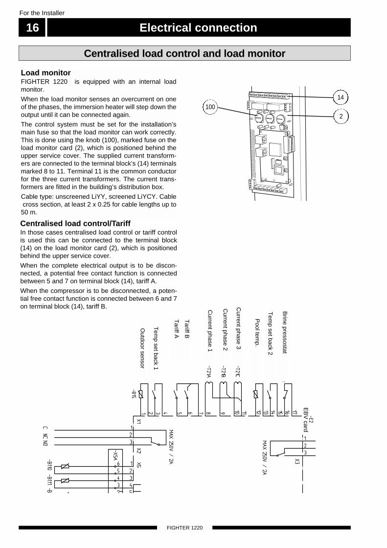
Centralised load control/TariffIn those cases centralised load control or tariff controlis used this can be connected to the terminal block(14) on the load monitor card (2), which is positionedbehind the upper service cover.
When the complete electrical output is to be discon-nected, a potential free contact function is connectedbetween 5 and 7 on terminal block (14), tariff A.
When the compressor is to be disconnected, a poten-tial free contact function is connected between 6 and 7on terminal block (14), tariff B.
Load monitorFIGHTER 1220 is equipped with an internal loadmonitor.
When the load monitor senses an overcurrent on oneof the phases, the immersion heater will step down theoutput until it can be connected again.
The control system must be set for the installation’smain fuse so that the load monitor can work correctly.This is done using the knob (100), marked fuse on theload monitor card (2), which is positioned behind theupper service cover. The supplied current transform-ers are connected to the terminal block’s (14) terminalsmarked 8 to 11. Terminal 11 is the common conductorfor the three current transformers. The current trans-formers are fitted in the building’s distribution box.
Cable type: unscreened LiYY, screened LiYCY. Cable cross section, at least 2 x 0.25 for cable lengths up to
50 m.
Centralised load control and load monitor
14
2100
Brine pressostat
Tem
p set back 2
Pool tem
p.
Current phase 3
Current phase 2
Current phase 1
Tariff B
Tariff A
EB
V card
Tem
p set back 1
Outdoor sensor
Electrical connection 17For the Installer
FIGHTER 1220
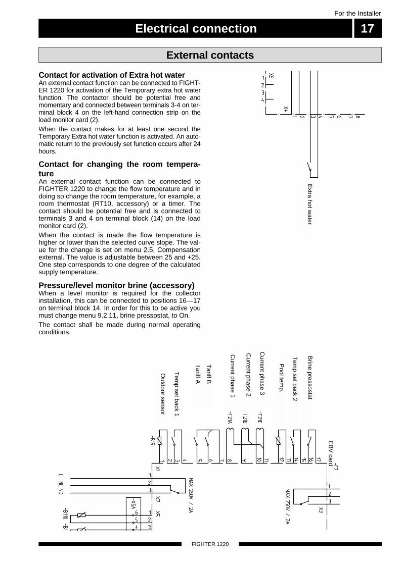
Contact for changing the room tempera-tureAn external contact function can be connected toFIGHTER 1220 to change the flow temperature and indoing so change the room temperature, for example, aroom thermostat (RT10, accessory) or a timer. Thecontact should be potential free and is connected toterminals 3 and 4 on terminal block (14) on the loadmonitor card (2).When the contact is made the flow temperature ishigher or lower than the selected curve slope. The val-ue for the change is set on menu 2.5, Compensationexternal. The value is adjustable between 25 and +25.One step corresponds to one degree of the calculatedsupply temperature.
Pressure/level monitor brine (accessory)When a level monitor is required for the collectorinstallation, this can be connected to positions 16—17on terminal block 14. In order for this to be active youmust change menu 9.2.11, brine pressostat, to On.The contact shall be made during normal operating conditions.
Contact for activation of Extra hot waterAn external contact function can be connected to FIGHT-ER 1220 for activation of the Temporary extra hot waterfunction. The contactor should be potential free andmomentary and connected between terminals 3-4 on ter-minal block 4 on the left-hand connection strip on theload monitor card (2).When the contact makes for at least one second theTemporary Extra hot water function is activated. An auto-matic return to the previously set function occurs after 24hours.
External contactsE
BV
card
Brine pressostat
Tem
p set back 2
Pool tem
p.
Current phase 3
Current phase 2
Current phase 1
Tariff B
Tariff A
Tem
p set back 1
Outdoor sensor
Extra hot w
ater
Electrical connection
FIGHTER 1220
For the Installer
18
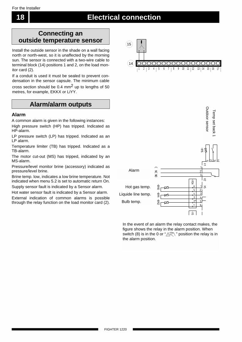
Install the outside sensor in the shade on a wall facingnorth or north-west, so it is unaffected by the morningsun. The sensor is connected with a two-wire cable toterminal block (14) positions 1 and 2, on the load mon-itor card (2).
If a conduit is used it must be sealed to prevent con-densation in the sensor capsule. The minimum cable
cross section should be 0.4 mm2 up to lengths of 50metres, for example, EKKX or LiYY.
AlarmA common alarm is given in the following instances:High pressure switch (HP) has tripped. Indicated asHP-alarm. LP pressure switch (LP) has tripped. Indicated as anLP alarm. Temperature limiter (TB) has tripped. Indicated as aTB-alarm. The motor cut-out (MS) has tripped, indicated by anMS-alarm. Pressure/level monitor brine (accessory) indicated aspressure/level brine. Brine temp. low, indicates a low brine temperature. Notindicated when menu 5.2 is set to automatic return On. Supply sensor fault is indicated by a Sensor alarm. Hot water sensor fault is indicated by a Sensor alarm.External indication of common alarms is possiblethrough the relay function on the load monitor card (2).
Alarm/alarm outputs
In the event of an alarm the relay contact makes, thefigure shows the relay in the alarm position. Whenswitch (8) is in the 0 or “ ” position the relay is inthe alarm position.
Connecting an outside temperature sensor
1 2 3 4 5 6 7 8
15
149 10 11 12 13 14 15 16 17
Tem
p set back 1
Outdoor sensor
Hot gas temp.
Bulb temp.
Liquide line temp.
Alarm
Commissioning and adjusting 19For the Installer
FIGHTER 1220
The heating medium system is filled with water untilthe required pressure is reached and then vented.
Before starting up the system, check that the heating,collector and hot water circuits are full and thoroughlyvented. Check the pipe system for leaks.
Filling the heating medium system
Preparations
NOTE! The compressor must not be forced tostart with periods shorter that 1 start
per 15 minutes.
Fighter 1220 is equipped with a soft-starter relay (97)that limits the inrush current on the compressor to max30A.The compressor must not be forced to start with peri-ods shorter that 1 start per 15 minutes.
Soft-start relay
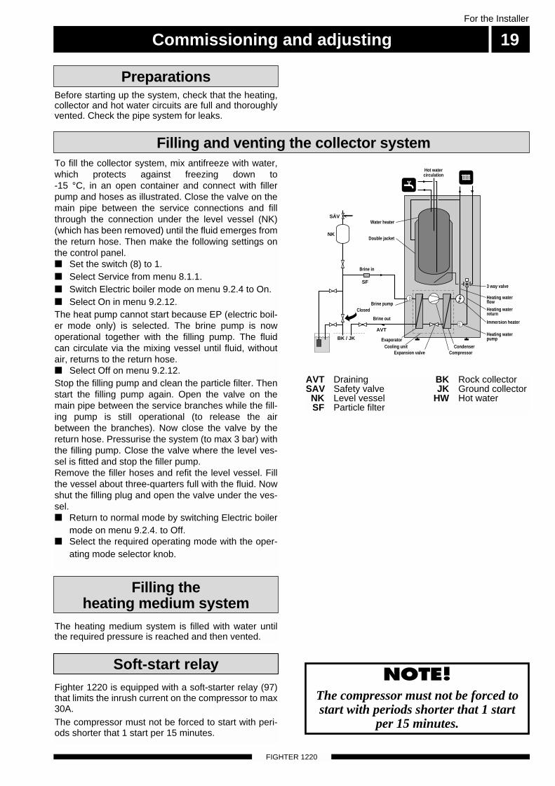
To fill the collector system, mix antifreeze with water,which protects against freezing down to -15 °C, in an open container and connect with fillerpump and hoses as illustrated. Close the valve on themain pipe between the service connections and fillthrough the connection under the level vessel (NK)(which has been removed) until the fluid emerges fromthe return hose. Then make the following settings onthe control panel.■ Set the switch (8) to 1.■ Select Service from menu 8.1.1.■ Switch Electric boiler mode on menu 9.2.4 to On.■ Select On in menu 9.2.12. The heat pump cannot start because EP (electric boil-er mode only) is selected. The brine pump is nowoperational together with the filling pump. The fluidcan circulate via the mixing vessel until fluid, withoutair, returns to the return hose. ■ Select Off on menu 9.2.12. Stop the filling pump and clean the particle filter. Thenstart the filling pump again. Open the valve on themain pipe between the service branches while the fill-ing pump is still operational (to release the airbetween the branches). Now close the valve by thereturn hose. Pressurise the system (to max 3 bar) withthe filling pump. Close the valve where the level ves-sel is fitted and stop the filler pump.Remove the filler hoses and refit the level vessel. Fillthe vessel about three-quarters full with the fluid. Nowshut the filling plug and open the valve under the ves-sel.■ Return to normal mode by switching Electric boiler
mode on menu 9.2.4. to Off.■ Select the required operating mode with the oper-
ating mode selector knob.
Filling and venting the collector system
Evaporator
Brine pump
CompressorCondenser
Heating waterpump
Expansion valveCooling unit
Immersion heater
3 way valve
Double jacket
Water heater
Heating waterflow
Heating waterreturn
Hot watercirculation
AVT
Closed
BK / JK
NK
SÄV
SF
Brine in
Brine out
AVT DrainingSAV Safety valveNK Level vesselSF Particle filter
BK Rock collectorJK Ground collector
HW Hot water
Commissioning and adjusting20
FIGHTER 1220
For the Installer
Air is initially released from the hot water and ventingmay be necessary. If bubbling sounds can be heardfrom the heat pump, the entire system requires furtherventing. When the system has stabilised (correctpressure and all the air removed) the heating controlscan be set at the required value.
Check the fluid level in the level vessel (85). If the lev-el has dropped, close the valve under the vessel. Youcan then fill through the connection at the top of thevessel. After filling, open the valve again. To raise the pressure, close the valve on the incomingmain pipe when the brine pump (KBP) is running andthe level vessel (NK) is open, so that water is drawn infrom the vessel.
The siphon principle is used to empty the waterheater. This can be done either via the drain valve onthe incoming cold water pipe or by inserting a hoseinto the cold water connection.
Readjustment, brine side
Emptying the water heater
■ Set the switch (8) to 1.■ Check the settings on the display unit, and adjust
so there is a heating requirement.■ Select Service from menu 8.1.1.■ Switch Electric boiler mode on menu 9.2.4 to On.■ Select brine pump 10 days from menu 9.2.12 to
run the brine pump continuously for 10 days. After10 days the brine pump automatically returns tonormal operation.
■ Ensure the brine and heating medium pumps arevented and help the pumps to start if necessary.
■ Go to menu 5.0 which shows brine supply/return.Ensure that the temperature corresponds with theground/rock temperature, which indicates the brineflow.
■ Switch Electric boiler mode on menu 9.2.4 to Off.■ Select the required operating mode with the oper-
ating mode selector knob.The compressor will start, and go to menu 5.0.Read the brine temperatures. The differencebetween these two temperatures should be 2 —5°C when the system has come into balance. Ahigh difference indicates a low brine flow. A low dif-ference indicates a high brine flow.
■ Particular attention should be given to the level inthe collector system when initially using the heatpump. Some topping-up may be necessary.
■ Check the Flow temperature on menu 2.0 andReturn temperature on menu 2.7. The differencebetween these two temperatures, with floating con-densing, should be 5 — 10°C when the heat pumpheats the hot water without additional heat. A highdifference could depend on a low heat mediumflow.
■ Fill in the commissioning report on page 2.■ Set the control system to suit the needs of the
building.
Readjustment, heat mediumside
Start-up and inspection
Setting the heating controls 21
FIGHTER 1220
For the Installer
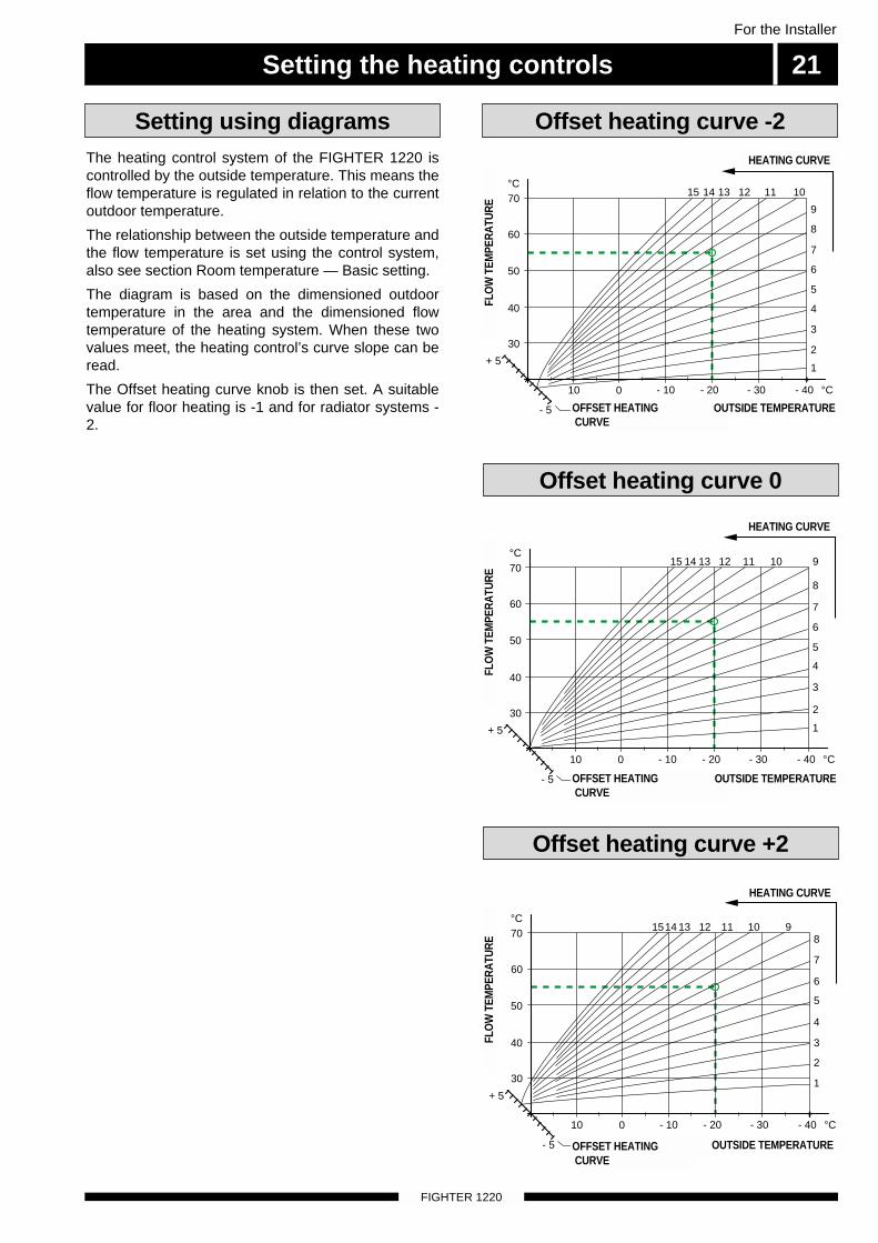
The heating control system of the FIGHTER 1220 iscontrolled by the outside temperature. This means theflow temperature is regulated in relation to the currentoutdoor temperature.
The relationship between the outside temperature andthe flow temperature is set using the control system,also see section Room temperature — Basic setting.
The diagram is based on the dimensioned outdoortemperature in the area and the dimensioned flowtemperature of the heating system. When these twovalues meet, the heating control’s curve slope can beread.
The Offset heating curve knob is then set. A suitablevalue for floor heating is -1 and for radiator systems -2.
Offset heating curve -2Setting using diagrams
30
40
50
60
70°C
FR
AM
LE
DN
ING
ST
EM
PE
RA
TU
R
- 40 °C
UTETEMPERATUR
- 10010 - 20 - 30
15 14 13 12 11 10 9
8
7
6
5
4
3
2
1
KURVLUTNING
- 5
+ 5
PARALLELLFÖRFLYTTNING
15 14 13 12 11 10
9
8
7
6
5
4
3
2
1
- 40 °C
UTETEMPERATUR
- 10010
- 5
+ 5
30
40
50
60
70°C
FR
AM
LE
DN
ING
ST
EM
PE
RA
TU
R
- 20 - 30
PARALLELLFÖRFLYTTNING
KURVLUTNING
1514 13 12 11 108
7
6
5
4
3
2
1
- 40 °C
UTETEMPERATUR
- 10010
- 5
+ 5
30
40
50
60
70°C
FR
AM
LE
DN
ING
ST
EM
PE
RA
TU
R
- 20 - 30
PARALLELLFÖRFLYTTNING
9
KURVLUTNING
Offset heating curve 0
Offset heating curve +2
HEATING CURVE
HEATING CURVE
HEATING CURVE
OFFSET HEATING CURVE
OFFSET HEATING CURVE
FLO
W T
EMPE
RA
TUR
EFL
OW
TEM
PER
ATU
RE
FLO
W T
EMPE
RA
TUR
E
OUTSIDE TEMPERATURE
OUTSIDE TEMPERATURE
OUTSIDE TEMPERATUREOFFSET HEATING CURVE
A BI II III I II
5 0 . 0 CH o t w a t e r t e m p e r a t u r e
13.431.0
A
ControlFor the Installer
22
FIGHTER 1220
The menu tree shows all the menus. Three differentmenu types can be chosen.
Normal, covers the normal user's needs.
Extended, shows all menus except the servicemenus.
Service, shows all menus, returns to Normal 30minutes after the last button was pressed.
Changing of menu type is done from menu 8.1.1
Example■ The starting point is menu 1.0.
■ Press the minus button to move to menu 8.0.
■ Press the enter button to move to menu 8.1.0.
■ Press the enter button to move to menu 8.1.1.
■ Press the enter button to allow the value to bechanged.
■ Change the value by pressing the plus or minusbuttons.
■ Confirm the chosen value by pressing the enter but-ton.
■ Press the operating mode button followed by enter(quick movement) to return to menu 1.0.
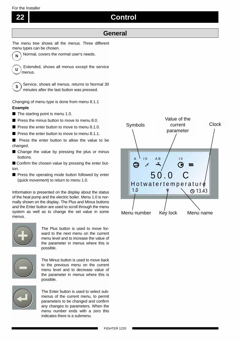
Information is presented on the display about the statusof the heat pump and the electric boiler. Menu 1.0 is nor-mally shown on the display. The Plus and Minus buttonsand the Enter button are used to scroll through the menusystem as well as to change the set value in somemenus.
The Plus button is used to move for-ward to the next menu on the currentmenu level and to increase the value ofthe parameter in menus where this ispossible.
The Minus button is used to move backto the previous menu on the currentmenu level and to decrease value ofthe parameter in menus where this ispossible.
The Enter button is used to select sub-menus of the current menu, to permitparameters to be changed and confirmany changes to parameters. When themenu number ends with a zero thisindicates there is a submenu.
N
U
S
General
Menu number Menu nameKey lock
ClockSymbolsValue of the
currentparameter
Control 23For the Installer
FIGHTER 1220
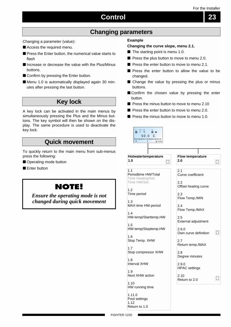
Changing a parameter (value):
■ Access the required menu.
■ Press the Enter button, the numerical value starts toflash
■ Increase or decrease the value with the Plus/Minusbuttons.
■ Confirm by pressing the Enter button.
■ Menu 1.0 is automatically displayed again 30 min-utes after pressing the last button.
Changing parameters
To quickly return to the main menu from sub-menuspress the following:
■ Operating mode button
■ Enter button
Quick movement
NOTE! Ensure the operating mode is notchanged during quick movement
A key lock can be activated in the main menus bysimultaneously pressing the Plus and the Minus but-tons. The key symbol will then be shown on the dis-play. The same procedure is used to deactivate thekey lock.
Key lock
1.1Periodtime HW/TotalTime Heating/Set.Time HW/Set.
1.2Time period
1.3MAX-time HW-period
1.4HW-temp/Starttemp.HW
1.5HW-temp/Stoptemp.HW
1.6Stop Temp. XHW
1.7Stop compressor XHW
1.8Interval XHW
1.9Next XHW action
1.10HW running time
1.11.0Pool settings1.12Return to 1.0
Hotwatertemperature1.0
2.1Curve coefficient
2.2Offset heating curve
2.3Flow Temp./MIN
2.4Flow Temp./MAX
2.5External adjustment
2.6.0Own curve definition
2.7Return temp./MAX
2.8Degree minutes
2.9.0HPAC settings
2.10Return to 2.0
Flow temperature2.0 ↵
↵
↵
↵
A BI II III I II
5 0 . 0 CH o t w a t e r t e m p e r a t u r e
13.431.0
A
ExampleChanging the curve slope, menu 2.1. ■ The starting point is menu 1.0.
■ Press the plus button to move to menu 2.0.
■ Press the enter button to move to menu 2.1.
■ Press the enter button to allow the value to bechanged.
■ Change the value by pressing the plus or minusbuttons.
■ Confirm the chosen value by pressing the enter button.
■ Press the minus button to move to menu 2.10
■ Press the enter button to move to menu 2.0.
■ Press the minus button to move to menu 1.0.
Control
FIGHTER 1220
For the Installer
24
2.6.1Flow temp.at +20ºC
2.6.2Flow temp.at -20ºC
2.6.3Set temperature
2.6.4Flow temp at set
2.6.5Return to 2.6.0
A BI II III I II
5 0 . 0 CH o t w a t e r t e m p e r a t u r e
13.431.0
A
1.1Periodtime HW/TotalTime Heating/Set.Time HW/Set.
1.2Time period
1.3MAX-time HW-period
1.4HW-temp/Starttemp.HW
1.5HW-temp/Stoptemp.HW
1.6Stop Temp. XHW
1.7Stop compressor XHW
1.8Interval XHW
1.9Next XHW action
1.10HW running time
1.11.0Pool settings
1.12Return to 1.0
1.11.1Pooltemperatur/inst.
1.11.2Diff. pool/min-temp
1.11.3Poolperiod
1.11.4Poolpause
1.11.5Sensor typ
1.11.6Return to 1.11.0
Hotwatertemperature1.0
4.1Outdoor avg. temp.
4.2Return to 4.0
Outdoor temperature4.0
5.1Brine ret. temp/MIN
5.2Autoreset brinealarm
5.3Time between starts
5.4Compr. starts at
5.5Time to startStatus
5.6Number of starts
5.9Comp. acc. run time
5.11Hot gas temp.
5.12Liquide line temp.
5.13Bulb temperature
5.14Compressor type
5.21Return to 5.0
Brine in-/out- temp.5.0
2.1Curve coefficient
2.2Offset heating curve
2.3Flow Temp./MIN
2.4Flow Temp./MAX
2.5External adjustment
2.6.0Own curve definition
2.7Return temp./MAX
2.8Degree minutes
2.10Return to 2.0
Flow temperature2.0 ↵
↵
↵
↵
↵
↵
↵
↵
↵
↵
↵
Control 25For the Installer
FIGHTER 1220
A BI II III I II
5 0 . 0 CH o t w a t e r t e m p e r a t u r e
13.431.0
A
8.1.0Display settings
8.2.0Operating mode
8.3.0Current limiter
8.4Return to 8.0 ↵
7.1Date
7.2Time
7.3.0Temp set back time 1
7.4.0Temp set back time 2
7.5.0Timer XHW
7.7Reset timers
7.8Return to 7.0
7.3.1Heating sys per. 1
7.3.2Set back temp. +/-
7.3.3 - 7.3.9Set time Monday - Sunday
7.3.10Return to 7.3.0 ↵
↵
8.1.1Operation mode types
8.1.2Language
8.1.3Contrast
8.1.4Light intensity
8.1.5Return to 8.1.0 ↵
↵
8.2.1Summer mode temp.
8.2.2Winter mode temp.
8.2.3Return to 8.2.0
↵
7.4.1Heating sys per. 2
7.4.2Set back temp. +/-
7.4.3 - 7.4.9Set time Monday - Sunday
7.4.10Return to 7.4.0 ↵
↵
7.5.1Timer Extra HW
7.5.2 Extra HW Monday - Sunday
7.5.3Return to 7.5.0 ↵
↵
↵
Clock7.0
Other settings8.0 ↵↵
↵
8.3.1Current phase 1
8.3.2Current phase 2
8.3.3Current phase 3
8.3.4Fuse size
8.3.5Max elec. power
8.3.6EBV value
8.3.7Return to 8.3.0
↵
↵
Control
FIGHTER 1220
For the Installer
26
A BI II III I II
5 0 . 0 CH o t w a t e r t e m p e r a t u r e
13.431.0
A
9.1.0Add. heat settings
9.2.0Operating mode set
9.3Quick start
9.4.0TEST/Forced operat.
9.5.0 - 9.8.0Log 1. - 4.
9.9Return to 9.0
9.1.1Start BIN 3 stepStart LIN 3 stepStart BIN 7 step
9.1.2Diff. BIN 3 stepDiff. LIN 3 stepDiff. BIN 7 step
9.1.3Add heat run time
9.1.4Return to 9.1.0
Service menues9.0
↵9.2.1Max HW temp
9.2.2Flow diff HP
9.2.3Diff HP Add
9.2.4Electric boiler
9.2.5System 2 Present
9.2.6Room disp Present
9.2.7Circ. pump 1
9.2.8Circ. pump 2
9.2.9.0Floor drying set
9.2.10Pool control
9.2.11Brine pressostat
9.2.12Brinepump 10 days
9.2.14Factory setting
9.2.15RCU Present
9.2.16HPAC Present
9.2.17Return to 9.2.0 ↵
↵
9.2.9.1Floor drying
9.2.9.2Numb. of days per. 1
9.2.9.3Temp. period 1
9.2.9.4Numb. of days per. 2
9.2.9.5Temp. period 2
9.2.9.6Return to 9.2.9.0 ↵
↵
↵
↵
Control 27For the Installer
FIGHTER 1220
Main menus
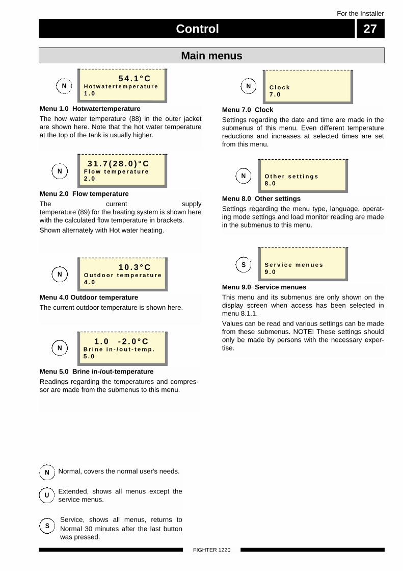
Menu 1.0 HotwatertemperatureThe how water temperature (88) in the outer jacketare shown here. Note that the hot water temperatureat the top of the tank is usually higher.
Menu 2.0 Flow temperatureThe current supply temperature (89) for the heating system is shown herewith the calculated flow temperature in brackets.
Shown alternately with Hot water heating.
Menu 4.0 Outdoor temperature The current outdoor temperature is shown here.
Menu 5.0 Brine in-/out-temperatureReadings regarding the temperatures and compres-sor are made from the submenus to this menu.
Menu 8.0 Other settingsSettings regarding the menu type, language, operat-ing mode settings and load monitor reading are madein the submenus to this menu.
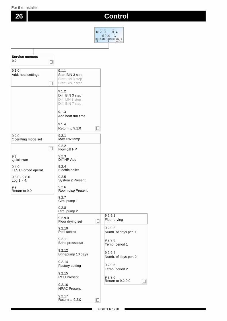
Menu 9.0 Service menuesThis menu and its submenus are only shown on the display screen when access has been selected in menu 8.1.1.
Values can be read and various settings can be madefrom these submenus. NOTE! These settings shouldonly be made by persons with the necessary exper-tise.
5 4 . 1 ° CH o t w a t e r t e m p e r a t u r e1 . 0
3 1 . 7 ( 2 8 . 0 ) ° CF l o w t e m p e r a t u r e2 . 0
1 0 . 3 ° CO u t d o o r t e m p e r a t u r e4 . 0
Menu 7.0 ClockSettings regarding the date and time are made in thesubmenus of this menu. Even different temperaturereductions and increases at selected times are setfrom this menu.
C l o c k7 . 0
O t h e r s e t t i n g s8 . 0
S e r v i c e m e n u e s9 . 0
N
N
N
N
N
N
S
N
U
S
Normal, covers the normal user's needs.
Extended, shows all menus except theservice menus.
Service, shows all menus, returns toNormal 30 minutes after the last buttonwas pressed.
1 . 0 - 2 . 0 ° CB r i n e i n - / o u t - t e m p .5 . 0
Control
FIGHTER 1220
For the Installer
28
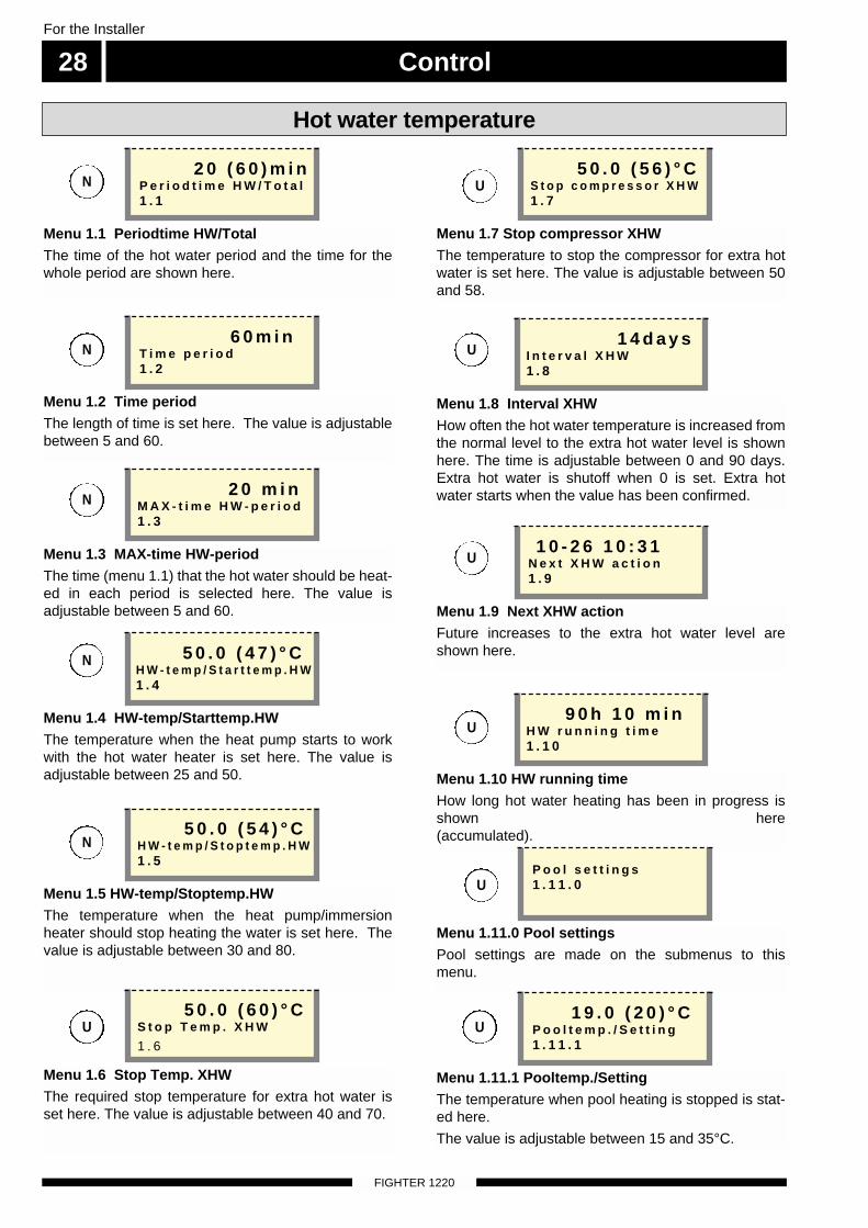
Menu 1.1 Periodtime HW/TotalThe time of the hot water period and the time for thewhole period are shown here.
Menu 1.3 MAX-time HW-periodThe time (menu 1.1) that the hot water should be heat-ed in each period is selected here. The value isadjustable between 5 and 60.
Hot water temperature
Menu 1.4 HW-temp/Starttemp.HWThe temperature when the heat pump starts to workwith the hot water heater is set here. The value isadjustable between 25 and 50.
Menu 1.5 HW-temp/Stoptemp.HWThe temperature when the heat pump/immersionheater should stop heating the water is set here. Thevalue is adjustable between 30 and 80.
Menu 1.8 Interval XHWHow often the hot water temperature is increased fromthe normal level to the extra hot water level is shownhere. The time is adjustable between 0 and 90 days.Extra hot water is shutoff when 0 is set. Extra hotwater starts when the value has been confirmed.
Menu 1.9 Next XHW actionFuture increases to the extra hot water level areshown here.
Menu 1.10 HW running timeHow long hot water heating has been in progress isshown here(accumulated).
2 0 ( 6 0 ) m i nP e r i o d t i m e H W / T o t a l1 . 1
1 4 d a y sI n t e r v a l X H W1 . 8
9 0 h 1 0 m i nH W r u n n i n g t i m e1 . 1 0
2 0 m i nM A X - t i m e H W - p e r i o d1 . 3
5 0 . 0 ( 4 7 ) ° CH W - t e m p / S t a r t t e m p . H W1 . 4
5 0 . 0 ( 5 4 ) ° CH W - t e m p / S t o p t e m p . H W1 . 5
Menu 1.6 Stop Temp. XHWThe required stop temperature for extra hot water isset here. The value is adjustable between 40 and 70.
5 0 . 0 ( 6 0 ) ° CS t o p T e m p . X H W
1 . 6
1 0 - 2 6 1 0 : 3 1N e x t X H W a c t i o n 1 . 9
N
N
N
N
Menu 1.2 Time period The length of time is set here. The value is adjustablebetween 5 and 60.
6 0 m i nT i m e p e r i o d 1 . 2
N
U
U
Menu 1.7 Stop compressor XHWThe temperature to stop the compressor for extra hotwater is set here. The value is adjustable between 50and 58.
5 0 . 0 ( 5 6 ) ° CS t o p c o m p r e s s o r X H W1 . 7
U
U
U
Menu 1.11.0 Pool settingsPool settings are made on the submenus to thismenu.
P o o l s e t t i n g s1 . 1 1 . 0
Menu 1.11.1 Pooltemp./SettingThe temperature when pool heating is stopped is stat-ed here.
The value is adjustable between 15 and 35°C.
1 9 . 0 ( 2 0 ) ° CP o o l t e m p . / S e t t i n g1 . 1 1 . 1
U
U
Control 29For the Installer
FIGHTER 1220
Hot water temperature
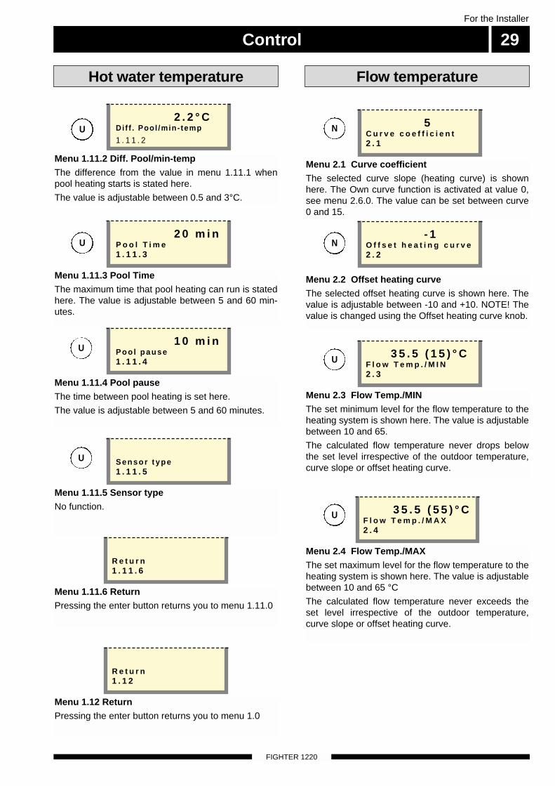
Menu 1.12 ReturnPressing the enter button returns you to menu 1.0
R e t u r n1 . 1 2
Menu 1.11.6 ReturnPressing the enter button returns you to menu 1.11.0
R e t u r n1 . 1 1 . 6
Menu 1.11.2 Diff. Pool/min-temp The difference from the value in menu 1.11.1 whenpool heating starts is stated here.
The value is adjustable between 0.5 and 3°C.
2 . 2 ° CDif f . Pool /min- temp
1 . 1 1 . 2
Menu 1.11.3 Pool TimeThe maximum time that pool heating can run is statedhere. The value is adjustable between 5 and 60 min-utes.
2 0 m i nP o o l T i m e1 . 1 1 . 3
Menu 1.11.4 Pool pauseThe time between pool heating is set here.
The value is adjustable between 5 and 60 minutes.
1 0 m i nPoo l pause1 . 1 1 . 4
U
U
U
Menu 1.11.5 Sensor typeNo function.
Sensor t ype1 . 1 1 . 5
U
Menu 2.4 Flow Temp./MAXThe set maximum level for the flow temperature to theheating system is shown here. The value is adjustablebetween 10 and 65 °C
The calculated flow temperature never exceeds the set level irrespective of the outdoor temperature,curve slope or offset heating curve.
Menu 2.1 Curve coefficientThe selected curve slope (heating curve) is shownhere. The Own curve function is activated at value 0,see menu 2.6.0. The value can be set between curve0 and 15.
Menu 2.2 Offset heating curveThe selected offset heating curve is shown here. Thevalue is adjustable between -10 and +10. NOTE! Thevalue is changed using the Offset heating curve knob.
Menu 2.3 Flow Temp./MINThe set minimum level for the flow temperature to theheating system is shown here. The value is adjustablebetween 10 and 65.
The calculated flow temperature never drops belowthe set level irrespective of the outdoor temperature,curve slope or offset heating curve.
3 5 . 5 ( 5 5 ) ° CF l o w T e m p . / M A X2 . 4
5C u r v e c o e f f i c i e n t2 . 1
- 1O f f s e t h e a t i n g c u r v e2 . 2
3 5 . 5 ( 1 5 ) ° CF l o w T e m p . / M I N2 . 3
U
U
N
N
Flow temperature
Control
FIGHTER 1220
For the Installer
30
Flow temperature
Menu 2.5 External adjustmentConnecting an external contact, see Electrical con-nections - External contacts, for example, a room ther-mostat (RT10 accessory) or a timer allows you to tem-porarily or periodically raise or lower the flow tempera-ture and with that the room temperature. When theexternal contact is made the calculated flow tempera-ture is changed by the number of degrees shownhere. The value is adjustable between -25 and +25.
Menu 2.6.0 Own curve definitionYou own curve definition is chosen here. This is anindividual linear curve with one break point. You selecta break point and the associated temperatures.NOTE! The Curve slope in menu 2.1 must be set to 0to activate this function.
Menu 2.6.1 Flow temp.at +20ºCThe flow temperature at an outside temperature of+20 is chosen here. The value is adjustable between0 and 60.
Menu 2.6.2 Flow temp.at -20ºCThe flow temperature at an outside temperature of -20is chosen here. The value is adjustable between 0 and60.
Menu 2.6.3 Set temperatureHere you select at what outside temperature the breakpoint shall occur. The value is adjustable between 0and 60.
1E x t e r n a l a d j u s t m e n t2 . 5
1 5 ° CF l o w t e m p . a t + 2 0 º C2 . 6 . 1
3 5 ° CF l o w t e m p . a t - 2 0 º C2 . 6 . 2
0 ° CS e t t e m p e r a t u r e2 . 6 . 3
O w n c u r v e d e f i n i t i o n2 . 6 . 0
U
U
U
U
U
Menu 2.7 Return temp./MAXHere the maximum return flow temperature is set forcompressor operation.
The value is adjustable between 40 and 60.
Menu 2.6.5 ReturnPressing the enter button returns you to menu 2.6.
Menu 2.6.4 Flow temp at setYou set the required flow temperature for the breakpoint here. The value can be set between curve 0 and60.
2 0 ° CF l o w t e m p a t s e t2 . 6 . 4
Menu 2.10 ReturnPressing the enter button returns you to menu 2.0.
R e t u r n2 . 1 0
Menu 2.8 Degree minutesCurrent value for number of degree-minutes. Forexample, this value can be changed to accelerate thestart of heating production. The value can be setbetween 100 and -800.
0D e g r e e m i n u t e s2 . 8
R e t u r n2 . 6 . 5
3 3 . 0 ( 4 7 ) ° CR e t u r n t e m p . / M A X2 . 7
U
U
U
Control 31For the Installer
FIGHTER 1220
Outside temperature
Menu 4.2 ReturnPressing the enter button returns you to menu 4.0.
Menu 4.1 Outdoor avg. temp.Average outdoor temperature during the last 24 hours.
R e t u r n4 . 2
O u t d o o r a v g . t e m p .4 . 1
N
Brine flow/return
Menu 5.5 StatusShows the compressor status for the heat pump.
Start in XX minutes, means the compressor will startas soon as the time condition permits.
Inactive means the compressor is at a stand still.
Compr. On means the compressor is running.
Brine pump On means the brine pump is running.
S t a r t i n 5 m i nS t a t u s5 . 5
Menu 5.3 Time between startsTime between compressor starts is set here. The val-ue is adjustable between 10 and 60.
2 0 m i nT i m e b e t w e e n s t a r t s5 . 3
N
N
Menu 5.4 Compr. starts atHow low the degree minutes may drop before the acompressor start can take place is set here. The valueis adjustable between -5 and -250.
- 6 0C o m p r . s t a r t s a t5 . 4
N
Menu 5.1 Brine ret. temp/MINThe lowest brine temperature is set here. The value isadjustable between 12 and -11 minutes. When a low-er temperature is selected OFF is shown, whichmeans the heat pump never gives an alarm for a lowbrine temperature.
- 4 . 0 ( O F F ) ° CB r i n e r e t . t e m p / M I N5 . 1
N
Menu 5.2 Autoreset brinealarmAutomatic restart after an HF alarm, when the temper-ature rises 3 °C above the selected alarm level (menu5.1) for the brine return is selected here. The value isadjustable On or Off.
O f fA u t o r e s e t b r i n e a l a r m5 . 2
N
Control
FIGHTER 1220
For the Installer
32
Brine flow/return
Menu 5.6 Number of startsThe accumulated number of starts with the compres-sor is shown here.
8 2N u m b e r o f s t a r t s 5 . 6
U
Menu 5.9 Comp. acc. run timeThe accumulated time that the compressor has beenin operation is shown here.
1 1 2 hC o m p . a c c . r u n t i m e5 . 9
U
Menu 5.11 Hot gas temp.The hot gas temperature is shown in this menu.
1 0 4 ° CH o t g a s t e m p .5 . 1 1
U
Menu 5.12 Liquide line Temp.The fluid line temperature is shown in this menu.
4 8 . 2 ° CL i q u i d e l i n e T e m p .5 . 1 2
U
Menu 5.13 Bulb temperatureThe suction gas temperature is shown in thismenu.
5 5 ° CB u l b t e m p e r a t u r e5 . 1 3
U
Menu 5.14 Compressor typeNo function.
N o r m a lC o m p r e s s o r t y p e5 . 1 4
U
Menu 5.21 ReturnPressing the enter button returns you to menu 5.0.
R e t u r n5 . 2 1
Menu 7.1 DateThe current date is set.
Menu 7.3.0 Day change period 1Settings, e.g. for night reduction can be selected in thesubmenus to this menu.
2 0 0 3 - 0 9 - 2 4D a t e7 . 1
T e m p s e t b a c k t i m e 17 . 3 . 0
Menu 7.3.1 Heating sys per. 1The shunt system to be affected by day change period1 is selected here. When shunt group 2 is installedboth Shunt 1 and 2 can be selected.
O f f H e a t i n g s y s p e r . 17 . 3 . 1
Menu 7.3.2 Set back temp. +/-Changes to the flow temperature with a day change,e.g. night reduction are set here. The value isadjustable between -10 and 10.
0S e t b a c k t e m p . + / -7 . 3 . 2
Menu 7.2 TimeHere the current time is set.
1 3 : 3 9T i m e7 . 2
Clock
U
U
Menu 7.3.3 — 7.3.9 Set Time Monday — SundayThe time for the day change, e.g. night reduction, ischosen here.
S e t T i m e M o n d a y7 . 3 . 3
U
N
N
U
Control 33For the Installer
FIGHTER 1220
Menu 7.3.10 ReturnPressing the enter button returns you to menu 7.3.0
R e t u r n
7 . 3 . 1 0
Clock
Menu 7.4.0 Temp set back time 2Settings, e.g. for night reduction can be selected in thesubmenus to this menu.
T e m p s e t b a c k t i m e 27 . 4 . 0
Menu 7.4.1 Heating sys per. 2The shunt system to be affected by day change period2 is selected here. When shunt group 2 is installedboth Shunt 1 and 2 can be selected.
H e a t i n g s y s p e r . 27 . 4 . 1
Menu 7.4.2 Set back temp. +/-Changes to the flow temperature with a day change,e.g. night reduction are set here. The value isadjustable between -10 and 10.
0S e t b a c k t e m p . + / -7 . 4 . 2
Menu 7.4.10 ReturnPressing the enter button returns you to menu 7.4.0
R e t u r n
7 . 4 . 1 0
U
U
Menu 7.4.3 — 7.4.9 Set Time Monday — SundayThe time for the day change, e.g. night reduction, ischosen here.
S e t T i m e M o n d a y7 . 4 . 3
U
U
Menu 7.5.0 Timer XHWSettings are made in the submenus of this menu whenextra hot water is required on a specific day.
T i m e r X H W7 . 5 . 0
Menu 7.5.2 — 7.5.8 Extra HW Monday — SundayHere you select the period for respective days whenextra hot water should be activated. Hours and min-utes for both start and stop are shown Equal values orthe stop time before the start time means that extrahot water is not activated.
0 3 : 3 0 – 0 6 : 1 5E x t r a H W M o n d a y7 . 5 . 2
Menu 7.5.9 ReturnPressing the enter button returns you to menu 7.4.0
R e t u r n
7 . 5 . 9
Menu 7.8 ReturnPressing the Enter button returns you to menu 7.0.
R e t u r n7 . 8
U
U
Menu 7.5.1 Timer Extra HWYou choose here whether the time setting should beOn or Off.
O f fT i m e r E x t r a H W7 . 5 . 1
U
Menu 7.7 Reset timersYou can chose here to reset the time settings. Auto-matic return to Off after one minute.
O f fR e s e t t i m e r s7 . 7
U
Control
FIGHTER 1220
For the Installer
34
Other settings
Menu 8.2.0 Operating modeSettings regarding auto mode can be made in the sub-menus to this menu.
O p e r a t i n g m o d e8 . 2 . 0
Menu 8.2.2 Winter mode temp.The average temperature when the heat pump is inauto mode shall switch to winter mode is chosen here.The circulation pump and immersion heater are acti-vated. The value is adjustable between 0 and 30.
1 5 ° CW i n t e r m o d e t e m p .8 . 2 . 2
Menu 8.2.1 Summer mode temp.The average temperature when the heat pump is inauto mode shall switch to summer mode is chosenhere. In summer mode the circulation pump andimmersion heater are blocked, only hot water is pro-duced. The value is adjustable between 0 and 30.
2 0 ° CS u m m e r m o d e T e m p .8 . 2 . 1
U
U
U
Menu 8.1.0 Display settingsSettings concerning language and menu type are seton the submenus to this menu.
D i s p l a y s e t t i n g s8 . 1 . 0
Menu 8.1.1 Operation mode typesThe menu type is chosen here: Normal, extended orservice.
Normal, covers the normal user's needs.
Extended, shows all menus except the servicemenus.
Service, shows all menus, returns to Normal 30minutes after the last button was pressed.
N o r m a lOpera t ion mode types8 . 1 . 1
Menu 8.1.5 ReturnPressing the enter button returns you to menu 8.1.0
R e t u r n8 . 1 . 5
Menu 8.1.2 LanguageLanguage settings are made here.
S v e n s k aL a n g u a g e8 . 1 . 2
Menu 8.1.4 Light intensityThe light intensity in idle mode is set here. The valueis adjustable between 0 and 2. Idle mode occurs 30minutes after the last button was pressed.
0=shutoff, 1=low, 2=average.
2L i g h t i n t e n s i t y8 . 1 . 4
Menu 8.1.3 ContrastThe display's contrast is set here. The value isadjustable between 0 and 31.
1 5C o n t r a s t8 . 1 . 3
N
U
N
N
U
N
U
S
Menu 9.5.17 ReturnPressing the enter button returns you to menu 8.2.0
R e t u r n8 . 2 . 3
Control 35For the Installer
FIGHTER 1220
Menu 8.3.0 Current limiterSettings and readings regarding the load monitor areset on the submenus to this menu.
C u r r e n t l i m i t e r8 . 3 . 0
Menu 8.3.5 Max elec. powerThe setting selected on the load monitor card (2) isshown here knob (101).
M a x e l e c . p o w e r8 . 3 . 5
Menu 9.5.17 ReturnPressing the enter button returns you to menu 8.3.0.
R e t u r n8 . 3 . 7
Menu 8.4 ReturnPressing the Enter button returns you to menu 8.0.
R e t u r n8 . 4
Menu 8.3.4 Fuse sizeThe setting selected on the load monitor card (2) isshown here knob (100).
1 6 AF u s e s i z e8 . 3 . 4
Menu 8.3.1 Current phase 1Shows the measured current from phase 1
3 . 5 AC u r r e n t p h a s e 18 . 3 . 1
Menu 8.3.2 Current phase 2Shows the measured current from phase 2
3 . 3 AC u r r e n t p h a s e 28 . 3 . 2
Menu 8.3.3 Current phase 3Shows the measured current from phase 3
3 . 3 AC u r r e n t p h a s e 38 . 3 . 3
Menu 8.3.6 EBV valueThe transfer value must be defined depending on thecurrent transformers used for the load monitor card.The value is adjustable between 100 and 900 in incre-ments of 10. The setting 300 applies for the suppliedcurrent transformers.
3 0 0E B V v a l u e8 . 3 . 6
U
U
U
U
U
U
U
Other settings
Service menus
FIGHTER 1220
For the Installer
36
Menu 9.5.17 ReturnPressing the enter button returns you to menu 9.1.0.
R e t u r n9 . 1 . 4
Settings additional heat Operating settings
Menu 9.1.1 Start BIN 3 stepDegree minute deficiency before additional heat isengaged. When the power step has reduced thedegree minutes deficiency by 100 in relation to the setstart value it is disengaged. The value is adjustablebetween -30 and -500.
- 4 0 0S t a r t B I N 3 s t e p9 . 1 . 1
Menu 9.1.3 Add heat run timeThe accumulated running time for the electric modulesince the first start is shown.
1 8A d d h e a t r u n t i m e9 . 1 . 3
S
S
Menu 9.1.2 Diff. BIN 3 stepDifference between engaging and disengaging theelectric step The value is adjustable between 0 and100.
1 0 0D i f f . B I N 3 s t e p9 . 1 . 2
S
Menu 9.1.0 Add. heat settingsSettings regarding additional heat in the heat pumpare made from the submenus in this menu.
A d d . h e a t s e t t i n g s9 . 1 . 0
S
Menu 9.2.0 Operating mode setSettings regarding additional heat, floor drying and areturn to the factory settings can be made on the sub-menus in this menu.
O p e r a t i n g m o d e s e t9 . 2 . 0
Menu 9.2.1 Max HW tempHere the maximum boiler temperature is shown. Thevalue is selected on the load monitor card using knob(102).
6 5 ° CM a x H W t e m p9 . 2 . 1
S
S
Menu 9.2.2 Flow diff HPWhen the current flow temperature deviates from theset value compared to that calculated the heat pumpis forced to stop/start irrespective of the degree minutefigure.
When the current flow temperature exceeds the cal-culated flow by the set value the degree minute figureis set to 1. The compressor stops when there is only aheating requirement.
When current flow temperature falls below the calcu-lated flow by the set value the degree minute figure isset to -60. This means the compressor will start. Whenthe value also fall below menu 9.2.3, the degreeminute figure can be set to -400. The value isadjustable between 3 and 25 °C.
1 0 ° CF l o w d i f f H P9 . 2 . 2
S
Menu 9.2.3 Diff HP AddWhen the current flow temperature drops below that cal-culated by the set value plus the value from menu 9.2.2the degree minute value is set to -400. This means thatthe additional heat can be engaged directly. The value isadjustable between 1 and 8°C.
3 ° CD i f f H P A d d9 . 2 . 3
S
Service menus 37For the Installer
FIGHTER 1220
Operating settings
Menu 9.2.5 System 2 Present This menu is used to select On or Off depending onwhether you have shunt group 2 (accessories needed).
O f fS y s t e m 2 P r e s e n t 9 . 2 . 5
Menu 9.2.6 Room disp PresentNo function
O f fR o o m d i s p P r e s e n t9 . 2 . 6
S
S
Menu 9.2.4 Electric boilerElectric boiler mode is activated when On is shown onthe display, otherwise Off is shown. When the electricboiler mode is activated the immersion heater respec-tive circulation pump cannot be blocked with the oper-ating mode button. Select Off to deactivate electricboiler mode and select the required operating modeusing the operating mode button.
O f fE l e c t r i c b o i l e r9 . 2 . 4
S
Menu 9.2.7 Circ. pump 1You choose here whether circulation pump 1 shouldrun constantly. The value is adjustable On or Off.
O f fC i r c . p u m p 19 . 2 . 7
S
Menu 9.2.8 Circ. pump 2You choose here whether circulation pump 2 shouldrun constantly. The value is adjustable On or Off.
O f fC i r c . p u m p 29 . 2 . 8
S
Menu 9.2.9.0 Floor drying setSettings for the floor drying program are made in thesubmenus to this menu.
F l o o r d r y i n g s e t9 . 2 . 9 . 0
S
Menu 9.2.9.1 Floor dryingThe floor drying program is chosen from this sub-menu. The options are Prog 1 On, Prog 2 On or OffThe heat pump must be in Winter mode, selected withthe operating mode button. Electric boiler mode, Menu9.2.4 can be used together with floor drying, for exam-ple, when the heat source is not installed.
In Prog 1 On, menus 9.2.9.2 — 9.2.9.5 are shown.After time period 1 switching to time period 2 thenreturn to normal settings.
In Prog 2 On, a fixed program over 11 days follows.The flow temperature is increased from 20°C to 45°Cfor 4 days, it then remains constant for 3 days. Thetemperature then steps down to 25°C for 4 days, andthen returns to the normal settings.
O f fF l o o r d r y i n g9 . 2 . 9 . 1
Menu 9.2.9.2 Numb. of days per. 1Selection of the number of days in period 1.
The value is adjustable between 1 to 5.
3 N u m b . o f d a y s p e r . 19 . 2 . 9 . 2
Menu 9.2.9.3 Temp. period 1Selection of the flow temperature in period 1.
The value is adjustable between 15 and 50°C.
2 5 ° CT e m p . p e r i o d 19 . 2 . 9 . 3
S
S
S
Menu 9.2.9.4 Numb. of days per. 2Selection of the number of days in period 2.
The value is adjustable between 1 to 5.
1 N u m b . o f d a y s p e r . 29 . 2 . 9 . 4
Menu 9.2.9.5 Temp. period 2Selection of the flow temperature in period 2.
The value is adjustable between 15 and 50°C.
4 0 ° CT e m p . p e r i o d 29 . 2 . 9 . 5
S
S
Service menus
FIGHTER 1220
For the Installer
38
Menu 9.2.10 Pool controlSettings whether pool control should be On or Off.Basic setting is Off
O f fP o o l c o n t r o l 9 . 2 . 1 0
S
Operating settings
Menu 9.2.9.6 ReturnPressing the enter button returns you to menu 9.2..9.0
R e t u r n9 . 2 . 9 . 6
S
Menu 9.2.11 Brine pressostatYou set here whether an external brinepressostat/load monitor is connected to the load moni-tor card.
O f fB r i n e p r e s s o s t a t9 . 2 . 1 1
S
Menu 9.2.12 Brinepump 10 daysThe brine pump can be active for 10 days when theinstallation is started. The basic setting is Off
O f fB r i n e p u m p 1 0 d a y s9 . 2 . 1 2
S
Menu 9.2.15 RCU PresentNo function.
O f fR C U P r e s e n t
9 . 2 . 1 5S
Menu 9.2.17 ReturnPressing the enter button returns you to menu 9.2.0
R e t u r n9 . 2 . 1 7
Menu 9.2.14 Factory settingReturn to the factory settings in FIGHTER 1220, Yesor No.
N oF a c t o r y s e t t i n g9 . 2 . 1 4
S
Menu 9.2.16 HPAC PresentHere you set whether HPAC is installed in the systemof not.
O f fH P A C P r e s e n t
9 . 2 . 1 6S
Service menus 39For the Installer
FIGHTER 1220
Quick start Alarm log
Menu 9.5.0 — 9.8.0 Log 1 — Log 4.The alarm logs are shown in the submenus of thismenu. Log 1 is the last alarm, log 2 the next last, etc.
L o g 1 .9 . 5 . 0
Menu 9.6 ReturnPressing the Enter button returns you to menu 9.0.
R e t u r n9 . 5 . 1 7
Menu 9.5.17 ReturnPressing the Enter button returns you to menu 9.5.
R e t u r n9 . 6
Menu 9.4.1.26 ReturnPressing the enter button returns you to menu 9.4.0.
R e t u r n9 . 4 . 1 . 2 6
S
Menu 9.3 Quick startFIGHTER 1220 starts within 3 minutes.
N oQ u i c k s t a r t9 . 3
S
TEST Forced driven operation
Menu 9.4.0 TEST/Forced operat.Test of outputs, automatic return after 8 hours. Onlyfor service personnel.
T E S T / F o r c e d o p e r a t .9 . 4 . 0S
Menu 9.4.1.0 Forced operationSelectable between On or Off.
O f fF o r c e d o p e r a t i o n9 . 4 . 1 . 0
S
Menu 9.4.1.1 — 9.4.1.25 Manual test of relays, opto and AD
R E 19 . 4 . 1 . 1
S
Menu 9.5.1 Time
Menu 9.5.2 Alarm type
Menu 9.5.3 Charging type
Menu 9.5.4 Brine in
Menu 9.5.5 Brine out
Menu 9.5.6 Outdoor temp.
Menu 9.5.7 Flow temp.
Menu 9.5.8 Return temp.
Menu 9.5.9 Hot water temp.
Menu 9.5.10 Hot gas temp.
Menu 9.5.11 Compr. time
Menu 9.5.12 Electric b. time
Menu 9.5.13 Relay 1-8
Menu 9.5.14 Relay 9-14
Menu 9.5.15 External input
Menu 9.5.16 Reset logg
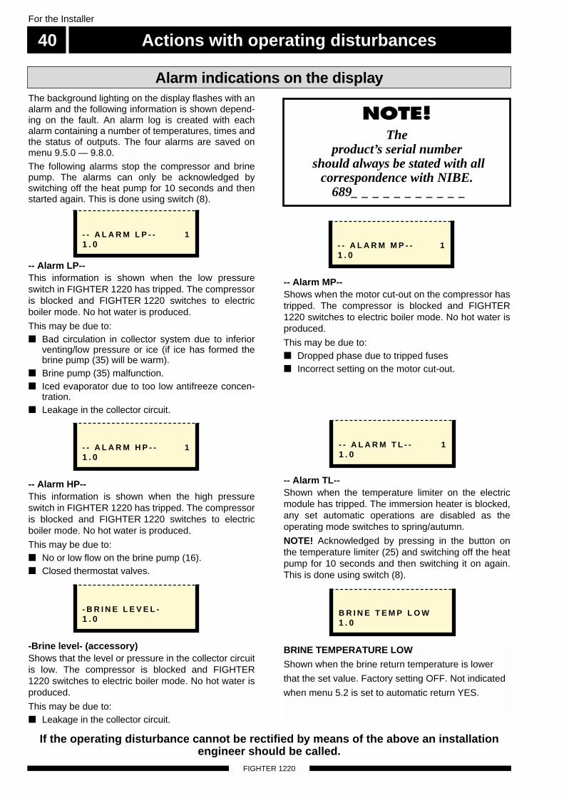
Actions with operating disturbances
FIGHTER 1220
For the Installer
40
NOTE! The
product’s serial numbershould always be stated with all
correspondence with NIBE.689_ _ _ _ _ _ _ _ _ _ _
-- Alarm LP--This information is shown when the low pressureswitch in FIGHTER 1220 has tripped. The compressoris blocked and FIGHTER 1220 switches to electricboiler mode. No hot water is produced.
This may be due to: ■ Bad circulation in collector system due to inferior
venting/low pressure or ice (if ice has formed thebrine pump (35) will be warm).
■ Brine pump (35) malfunction.■ Iced evaporator due to too low antifreeze concen-
tration.■ Leakage in the collector circuit.
Alarm indications on the displayThe background lighting on the display flashes with analarm and the following information is shown depend-ing on the fault. An alarm log is created with eachalarm containing a number of temperatures, times andthe status of outputs. The four alarms are saved onmenu 9.5.0 — 9.8.0. The following alarms stop the compressor and brinepump. The alarms can only be acknowledged byswitching off the heat pump for 10 seconds and thenstarted again. This is done using switch (8).
- - A L A R M L P - - 11 . 0
-- Alarm HP--This information is shown when the high pressureswitch in FIGHTER 1220 has tripped. The compressoris blocked and FIGHTER 1220 switches to electricboiler mode. No hot water is produced.
This may be due to:■ No or low flow on the brine pump (16).■ Closed thermostat valves.
- - A L A R M H P - - 11 . 0
-Brine level- (accessory)Shows that the level or pressure in the collector circuitis low. The compressor is blocked and FIGHTER1220 switches to electric boiler mode. No hot water isproduced.
This may be due to:■ Leakage in the collector circuit.
- B R I N E L E V E L -1 . 0
-- Alarm MP--Shows when the motor cut-out on the compressor hastripped. The compressor is blocked and FIGHTER1220 switches to electric boiler mode. No hot water isproduced.
This may be due to: ■ Dropped phase due to tripped fuses ■ Incorrect setting on the motor cut-out.
- - A L A R M M P - - 11 . 0
-- Alarm TL--Shown when the temperature limiter on the electricmodule has tripped. The immersion heater is blocked,any set automatic operations are disabled as theoperating mode switches to spring/autumn.
NOTE! Acknowledged by pressing in the button onthe temperature limiter (25) and switching off the heatpump for 10 seconds and then switching it on again.This is done using switch (8).
- - A L A R M T L - - 11 . 0
B R I N E T E M P L O W1 . 0
BRINE TEMPERATURE LOW
Shown when the brine return temperature is lower
that the set value. Factory setting OFF. Not indicated
when menu 5.2 is set to automatic return YES.
If the operating disturbance cannot be rectified by means of the above an installationengineer should be called.
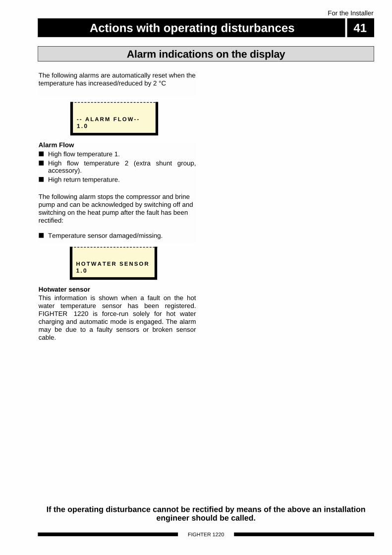
Actions with operating disturbances 41For the Installer
FIGHTER 1220
Alarm indications on the display
Hotwater sensorThis information is shown when a fault on the hotwater temperature sensor has been registered.FIGHTER 1220 is force-run solely for hot watercharging and automatic mode is engaged. The alarmmay be due to a faulty sensors or broken sensorcable.
H O T W A T E R S E N S O R1 . 0
- - A L A R M F L O W - -1 . 0
Alarm Flow■ High flow temperature 1.■ High flow temperature 2 (extra shunt group,
accessory).■ High return temperature.
The following alarm stops the compressor and brinepump and can be acknowledged by switching off andswitching on the heat pump after the fault has beenrectified:
■ Temperature sensor damaged/missing.
The following alarms are automatically reset when thetemperature has increased/reduced by 2 °C
If the operating disturbance cannot be rectified by means of the above an installationengineer should be called.
Actions with operating disturbances
FIGHTER 1220
For the Installer
42
NOTE! The
product’s serial numbershould always be stated with all
correspondence with NIBE.689_ _ _ _ _ _ _ _ _ _ _
Cause: Incorrect setting of Curve slope and/orOffset heating curve
Action: Adjust the setting.
Cause: Large amounts of hot water were used.
Action: Wait until the water heater reheats.
Cause: Compressor and/or immersion heater doesnot heat up.
Action: Check and replace blown circuit andmain fuses.
Cause: Too low start temperature setting on thecontrol system.
Action: Adjust the start temperature setting.
Cause: Possible earth circuit-breaker tripped.
Action: Reset the earth circuit-breaker, if the earthcircuit-breaker trips repeatedly, call anelectrician.
Cause: Compressor and electric module do notheat.
Action: Check and replace blown circuit and mainfuses.
Cause: The compressor does not run because of atoo low set value on the control curve.
Action: Check and possibly raise the Offset heatingcurve (knob on the front panel) or Curveslope.
Cause: The compressor standstills due to theinternal overheating protection tripping.
Action: Automatic resetting after cooling for a fewhours.
Cause: Possible earth circuit-breaker tripped.Action: Reset the earth circuit-breaker, if the earth
circuit-breaker trips repeatedly, call anelectrician.
Low hot water temperature or no hot water
In the event of malfunction or operating disturbances first check the points below:
High room temperature
Low room temperature
If the operating disturbance cannot be rectified by means of the above an installationengineer should be called.
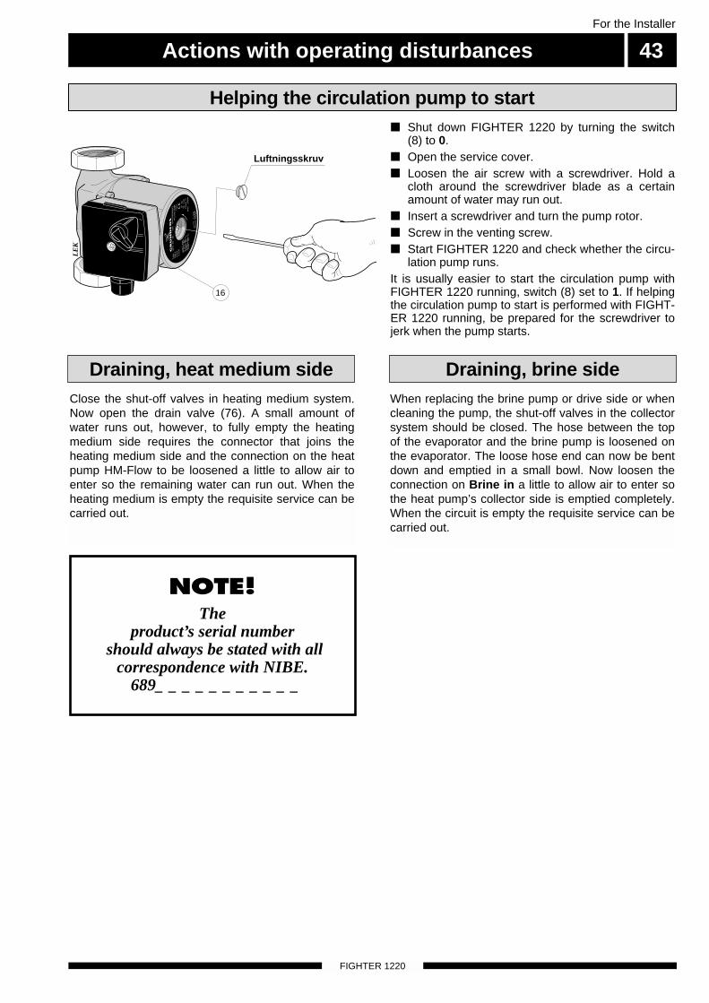
Actions with operating disturbances 43For the Installer
FIGHTER 1220
NOTE! The
product’s serial numbershould always be stated with all
correspondence with NIBE.689_ _ _ _ _ _ _ _ _ _ _
Close the shut-off valves in heating medium system.Now open the drain valve (76). A small amount ofwater runs out, however, to fully empty the heatingmedium side requires the connector that joins theheating medium side and the connection on the heatpump HM-Flow to be loosened a little to allow air toenter so the remaining water can run out. When theheating medium is empty the requisite service can becarried out.
When replacing the brine pump or drive side or whencleaning the pump, the shut-off valves in the collectorsystem should be closed. The hose between the topof the evaporator and the brine pump is loosened onthe evaporator. The loose hose end can now be bentdown and emptied in a small bowl. Now loosen theconnection on Brine in a little to allow air to enter sothe heat pump’s collector side is emptied completely.When the circuit is empty the requisite service can becarried out.
Draining, heat medium side Draining, brine side
■ Shut down FIGHTER 1220 by turning the switch(8) to 0.
■ Open the service cover.■ Loosen the air screw with a screwdriver. Hold a
cloth around the screwdriver blade as a certainamount of water may run out.
■ Insert a screwdriver and turn the pump rotor.■ Screw in the venting screw.■ Start FIGHTER 1220 and check whether the circu-
lation pump runs.It is usually easier to start the circulation pump withFIGHTER 1220 running, switch (8) set to 1. If helpingthe circulation pump to start is performed with FIGHT-ER 1220 running, be prepared for the screwdriver tojerk when the pump starts.
Helping the circulation pump to start
Luftningsskruv
16
LE
K
GR
UN
DFO
SType
UP
S25 -
60
130
P/N
:59526447
230V
-
HE
JS
AN
PC
;0017N
IBD
K50H
z
IP 44
TF
110
Cla
ss H
Max. 1
0bar
2.5
uF
45
0.2
065
0.3
090
0.4
0
1m(A
)P,
(W)
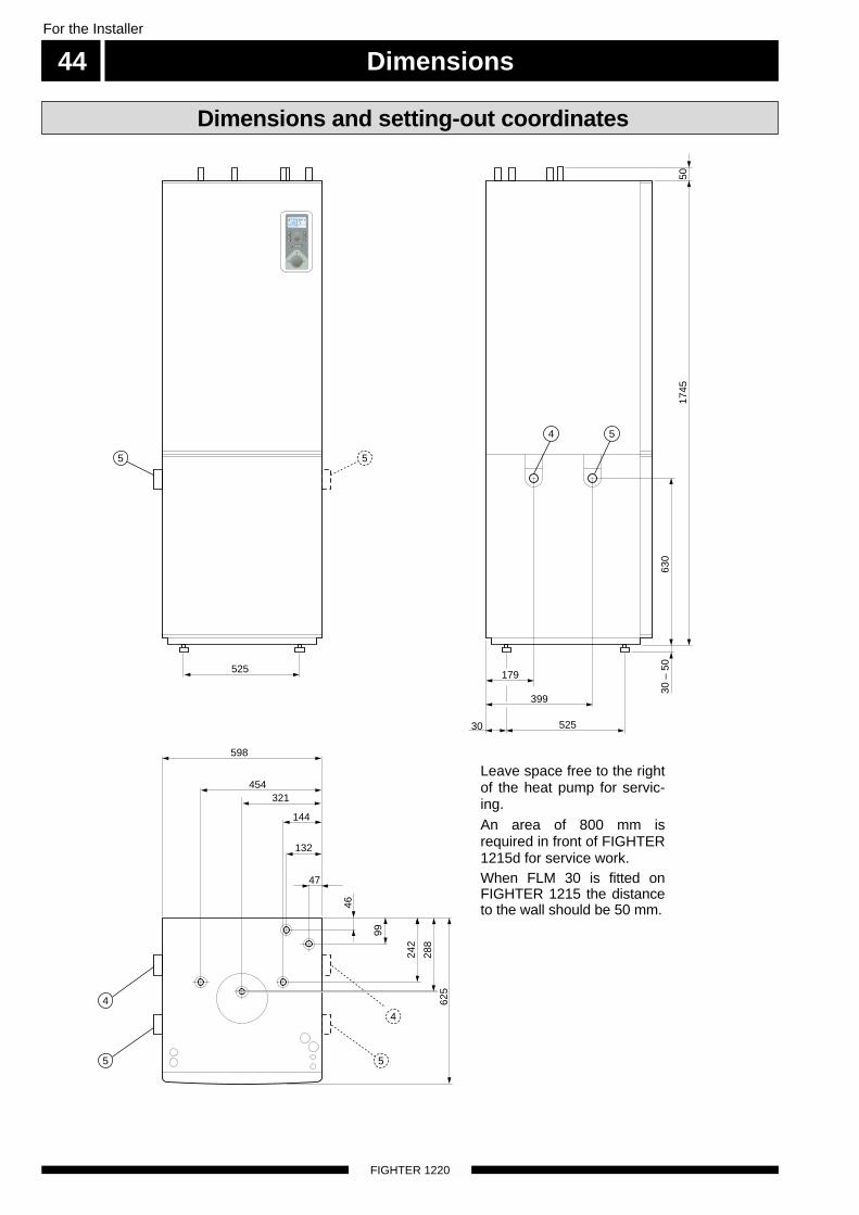
Dimensions
FIGHTER 1220
For the Installer
44
Dimensions and setting-out coordinates
Leave space free to the rightof the heat pump for servic-ing.An area of 800 mm isrequired in front of FIGHTER1215d for service work.When FLM 30 is fitted onFIGHTER 1215 the distanceto the wall should be 50 mm.
598
179
525
525
30
399
454
144
321
46
99
242
288
625
30 –
50
630
1745
50
132
47
5 5
54
4
5
4
5
A BI II III I II I II
5 0 . 0 CVa r m v a t t e n t e m p . 1 . 0
A B A B
List of components 45For the Installer
FIGHTER 1220
1 Miniature circuit-breaker
2 Load monitor card
3 Thermostat, standby mode
4 Collector connection, brine in (f)
5 Collector connection, brine out (r)
6 Terminal block, pumps, reversing valve
7 Service connection, high pressure
8 Switch, 1 0
9 Terminal block, incoming electric power
10 Contactor, electric module step 1
14 Terminal block, load monitor card
15 Outdoor temperature sensor
16 Heating medium pump
17 Evaporator
18 Condenser
19 Reversing valve, heating system/water heater
24 Electric module 9 kW, supplied connected 6 kW
25 Temperature limiter
26 Motor protection
27 Compressor
29 Relay card with power supply unit
32 Display unit
33 High pressure pressostat
34 CPU-unit, control system
35 Brine pump
39 Reset, motor protection
41 Low pressure pressostat
42 Service connection, low pressure
48 Expansion valve
52 Safety valve, collector side
58 Cover (enamel)
63 Particle filter (KB) R25 female.
65 Drying filter
67 Contactor, electric module step 2
69 Contactor, compressor operation
70 Connection, heating flow ø 22 mm o.d.
71 Connection, heating return ø 22 mm o.d.
72 * Hot water circulation (VVC)
Enamel: G 20
73 Cold water
Stainless steel: Ø 22 mm o.d.
Enamel: G 20
74 Hot water
Stainless steel: Ø 22 mm o.d.
Enamel: G 20
75 Venting valve, double jacket
76 Drainage for heating system
77 Venting valve, collector system
81 Particle filter (VB) R20 female.
85 Level vessel, connection to system, R25 male
86 Temperature sensor, Brine in
87 Temperature sensor, Brine out
88 Temperature sensor, hot water
89 Temperature sensor, HM-Flow, heating mediumflow
94 Temperature sensor, “HM-r”, heating mediumreturn
95 Type plate/serial number
96 Type plate, cooling section
97 Soft-start relay
99 Cable gland, incoming electricity
100 Knob, setting Fuse
101 Knob, setting Max electrical output
102 Knob, setting Max boiler temperature
110 Temperature sensor, hot gas temp, coolingcircuit
111 Temperature sensor, “liquide line temp, coolingcircuit
112 Temperature sensor, bulb temp, cooling circuit
115 Electric anode (enamel)
116 Transformer with LED, electric anode (enamel)
* Only enamel
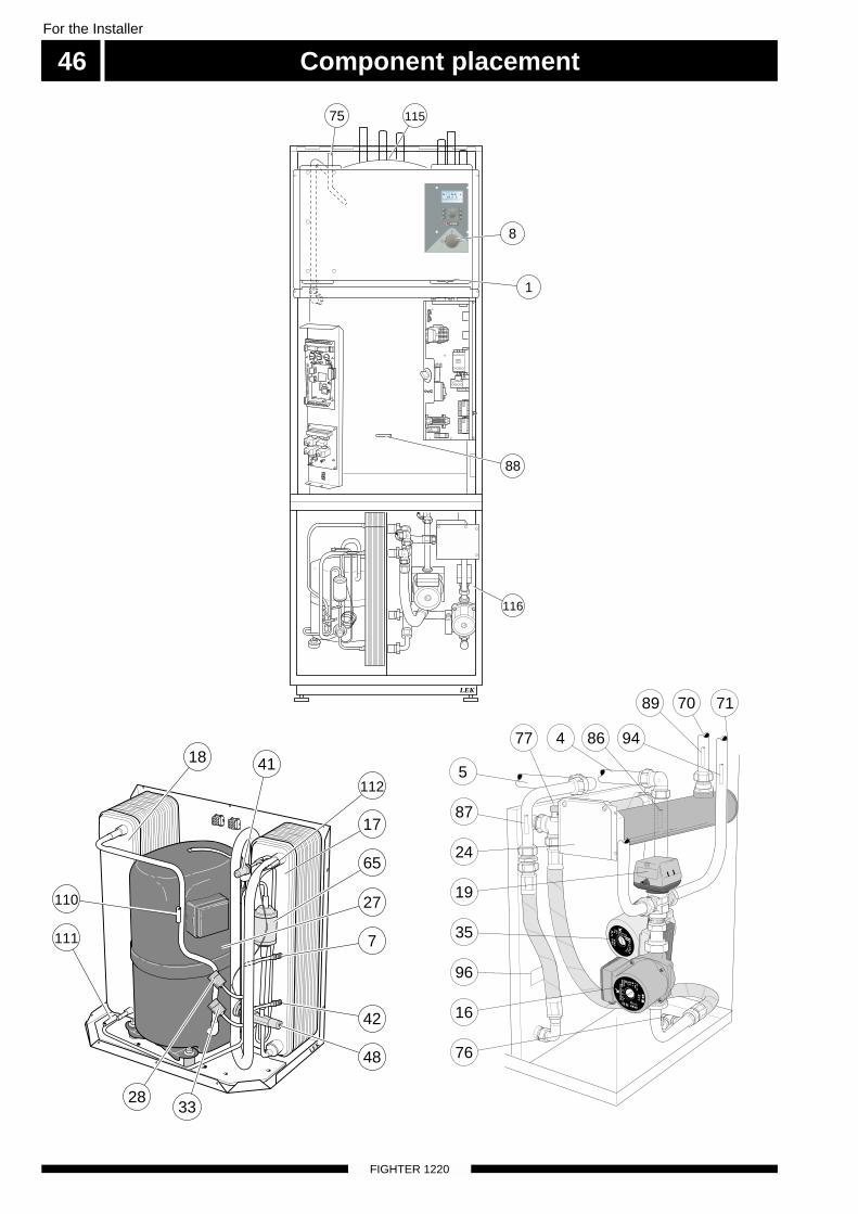
LEK
A BI II III I II I II
5 0 . 0 CVa r m v a t t e n t e m p . 1 . 0
8
88
75
116
115
1
Component placement46
FIGHTER 1220
For the Installer
LEK
4118
65
17
112
111
110 27
7
42
48
2833
LEK
16
76
87
24
35
96
19
4 86 9477
717089
5
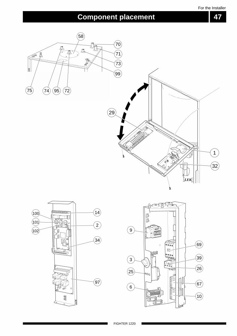
Component placement 47For the Installer
FIGHTER 1220
LEK
9
3 39
2625
6
69
67
10
LEK
1
32
29
LE
K
73
70
99
71
58
75 95 7274
LE
K
2
34
97
100
101
102
14
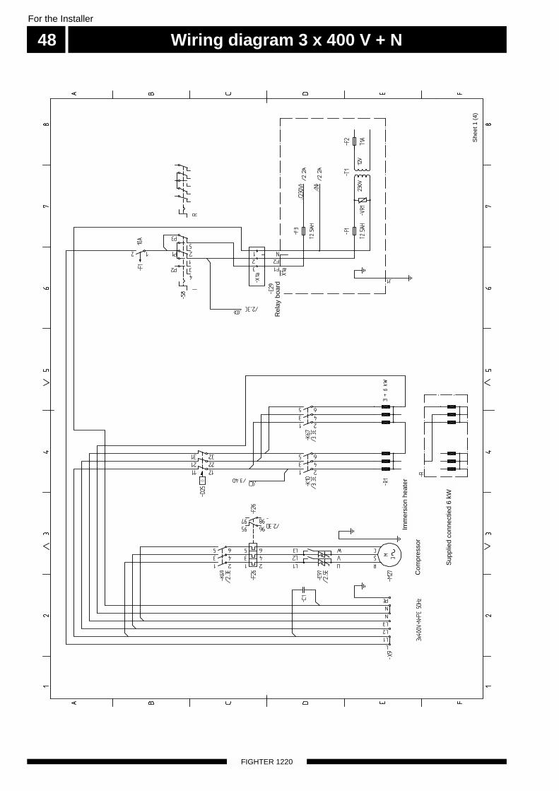
Wiring diagram 3 x 400 V + N
FIGHTER 1220
For the Installer
48
She
et 1
(4)
Com
pres
sor
Imm
ersi
on h
eate
r
Sup
plie
d co
nnec
tied
6 kW
Rel
ay b
oard
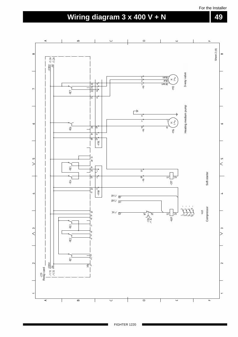
Wiring diagram 3 x 400 V + N 49For the Installer
FIGHTER 1220
She
et 2
(4)
Com
pres
sor
Sof
t-st
arte
r
Hea
ting
med
ium
pum
p3-
way
val
ve
Rel
ay c
ard
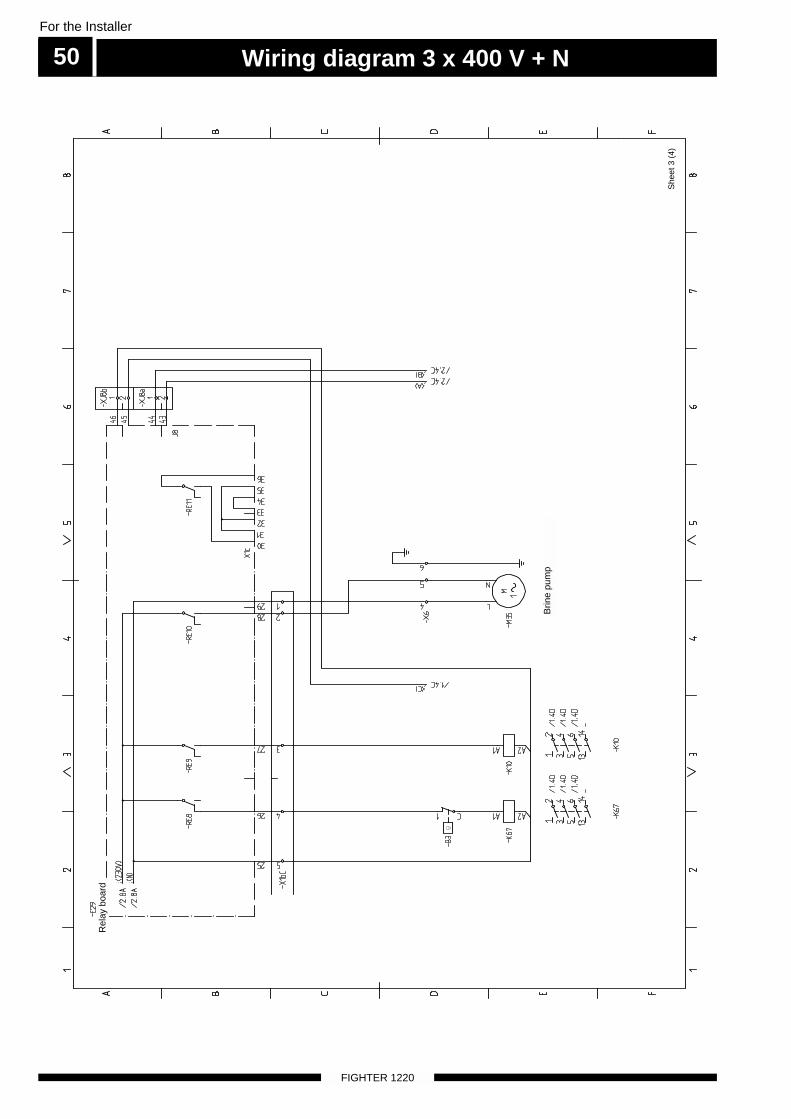
Wiring diagram 3 x 400 V + N
FIGHTER 1220
For the Installer
50
She
et 3
(4)
Brin
e pu
mp
Rel
ay b
oard
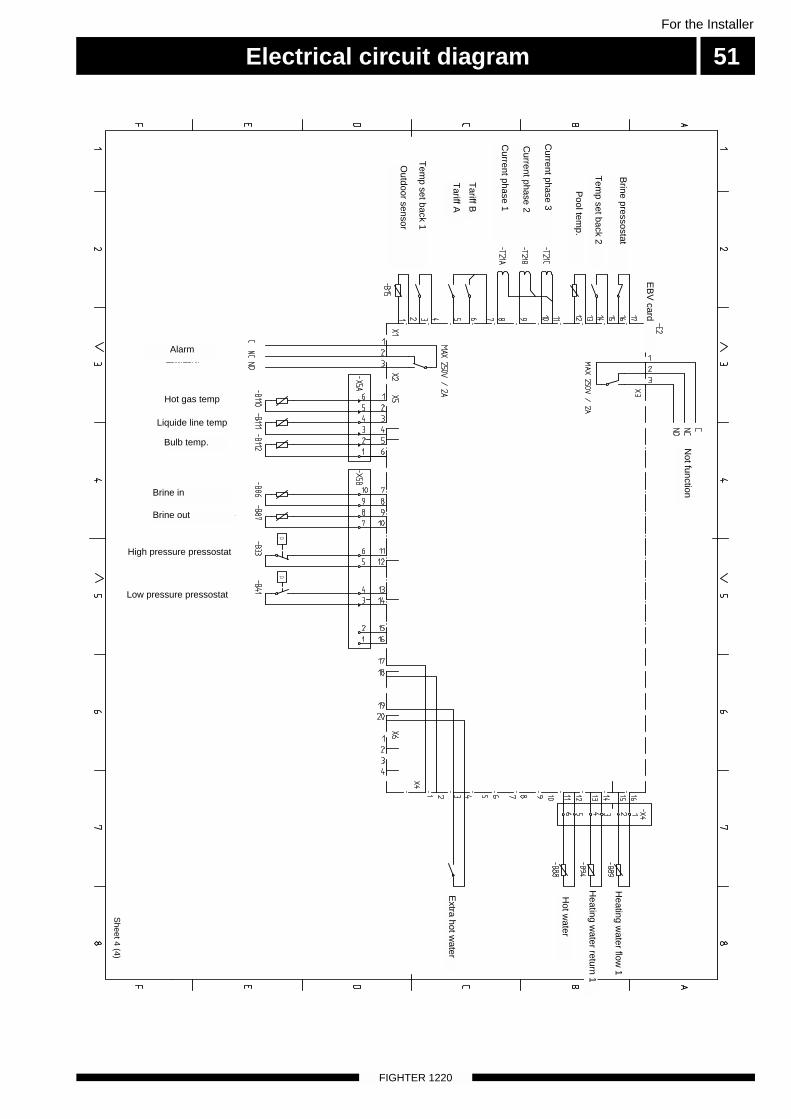
Electrical circuit diagram 51
FIGHTER 1220
For the Installer
Sheet 4 (4)
Brine pressostat
Tem
p set back 2
Pool tem
p.
Current phase 3
Current phase 2
Current phase 1
Not function
Tariff B
Tariff A
EB
V card
Tem
p set back 1
Outdoor sensor
Extra hot w
ater
Hot w
ater
Heating w
ater return 1
Heating w
ater flow 1
Hot gas temp
Bulb temp.
Liquide line temp
Brine in
Brine out
High pressure pressostat
Low pressure pressostat
Alarm
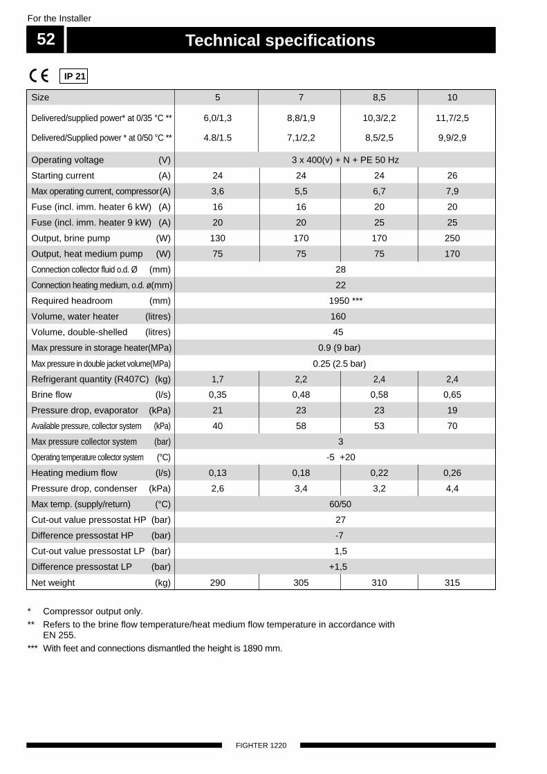
Technical specifications52
FIGHTER 1220
For the Installer
* Compressor output only.** Refers to the brine flow temperature/heat medium flow temperature in accordance with
EN 255.*** With feet and connections dismantled the height is 1890 mm.
Size 5 7 8,5 10
Operating voltage (V) 3 x 400(v) + N + PE 50 Hz
Max operating current, compressor(A) 3,6 5,5 6,7 7,9
Fuse (incl. imm. heater 9 kW) (A) 20 20 25 25
Output, heat medium pump (W) 75 75 75 170
Connection heating medium, o.d. ø(mm) 22
Max pressure in storage heater(MPa) 0.9 (9 bar)
Refrigerant quantity (R407C) (kg) 1,7 2,2 2,4 2,4
Pressure drop, evaporator (kPa) 21 23 23 19
Max pressure collector system (bar) 3
Heating medium flow (l/s) 0,13 0,18 0,22 0,26
Max temp. (supply/return) (°C) 60/50
IP 21
Volume, water heater (litres) 160
Starting current (A) 24 24 24 26
Fuse (incl. imm. heater 6 kW) (A) 16 16 20 20
Output, brine pump (W) 130 170 170 250
Connection collector fluid o.d. Ø (mm) 28
Volume, double-shelled (litres) 45
Max pressure in double jacket volume(MPa) 0.25 (2.5 bar)
Brine flow (l/s) 0,35 0,48 0,58 0,65
Available pressure, collector system (kPa) 40 58 53 70
Operating temperature collector system (°C) -5 +20
Cut-out value pressostat HP (bar) 27
Difference pressostat HP (bar) -7
Cut-out value pressostat LP (bar) 1,5
Net weight (kg) 290 305 310 315
Difference pressostat LP (bar) +1,5
Delivered/supplied power* at 0/35 °C ** 6,0/1,3 8,8/1,9 10,3/2,2 11,7/2,5
Delivered/Supplied power * at 0/50 °C ** 4.8/1.5 7,1/2,2 8,5/2,5 9,9/2,9
Required headroom (mm) 1950 ***
Pressure drop, condenser (kPa) 2,6 3,4 3,2 4,4
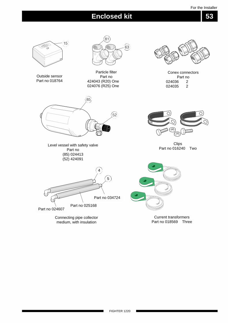
Enclosed kit 53For the Installer
FIGHTER 1220
LEK
LEK
LEK
LEK
Connecting pipe collectormedium, with insulation
Current transformersPart no 018569 Three
ClipsPart no 016240 Two
4
5
LEK
LEK
LEK
NIBE AB
Utetemperatur givare
Outdoor temperature sensor
Aussentemperatur fühler
Artikel 018764
Level vessel with safety valvePart no
(85) 024413 (52) 424091
15
85
Particle filterPart no
424043 (R20) One024076 (R25) One
Conex connectorsPart no
024036 2024035 2
63
81
Outside sensorPart no 018764
52
Part no 024607Part no 025168
Part no 034724

Accessories
FIGHTER 1220
54For the Installer
LEK
LEK
Exhaust air moduleFLM 30
Part no 089 268
Exhaust air moduleFLM 40
Part no 089 568
LEK
HPACPart no 089 265
Level monitor NV 10Part no 089 315
LEK
LEK
10
15 20
2530°C
Room thermostatRT 10
Part no 418 366
Extra shunt groupUsed when there is a need of two different supply tem-peratures. Installed externally, but controlled fromFIGHTER 1220.- Circulation pump- Shunt motor- Shunt valve- Circuit card- Pipe fittings- Sensor and cabling

55For the Installer
FIGHTER 1220

FIGHTER 1220
For the Installer
56

NIBE ABSWEDEN
R
Tel: +46 - (0)433 - 73 000Fax: +46 - (0)433 - 73 190E-mail: [email protected]
Box 14Järnvägsgatan 40SE-285 21 MARKARYD
PL
DE
NL
DK
FI
Vølund VarmeteknikFilial af NIBE AB
Brogårdsvej 7, 6920 Videbæk
Tel: 97 17 20 33Fax: 97 17 29 33E-mail: [email protected]
Haato VaraajatNIBE AB:n sivuliike
Pohjantähdentie 17, 01451 Vantaa
Puh: 09 - 274 697 0Fax: 09 - 274 697 40E-mail: [email protected]
NIBE Systemtechnik GmbHAm Reiherpfahl 3
29223 Celle
Tel: 05141/7546-0Fax: 05141/7546-99E-mail: [email protected]
NIBE Energietechniek B.VHofstraat 18
4797 AC WILLEMSTAD
Tel:1684 73249Fax: 1684 76642E-mail: [email protected]
NIBE-BIAWAR Sp. z o. o.Alejá Jána Pawła II 5715-703 BIAŁYSTOK
Tel: 85 662 84 90Fax: 85 662 84 16www.biawar.com.pl