Embed Size (px)
Citation preview
E02 Model E05 Model
E12 Model E25 Model
E75 Model
TABLE OF CONTENTSFeatures & Benefits ...................................................................2Model Nomenclature ..................................................................3Construction ...............................................................................3Specifications — Unmounted Pumps ........................................3Dimensions — Models E02, E05, E12 ......................................4Dimensions — Models E25, E75 ...............................................5Series CMD Pump Model String ................................................6Relief Valve Information .............................................................7Dimensions ................................................................................7Typical Piping Examples ............................................................7Liquid Compatibility Guide .........................................................8Liquid Compatibility Guide (Cont’d) ...............................................9Liquid Compatibility Guide (Cont’d) .............................................10Liquid Compatibility Guide (Cont’d) .............................................11Liquid Compatibility Guide (Cont’d) .............................................12Flow Curves .............................................................................13
PRODUCT DESCRIPTIONThe CMD Series™ Composite Mag Drive is a line of innovative non-metallic industrial gear pumps designed for optimal performance and simplicity of operation and maintenance. With absolutely no wetted metallic parts, the CMD Series™ is an ideal fit for many highly corrosive clean liquids used in the chemical processing, chemical dosing, pulp and paper and industrial water treatment industries.
OPERATING RANGE
SERIESNOMINAL FLOW MAXIMUM PRESSURE TEMPERATURE RANGE VISCOSITY RANGE
GPM LPM PSI Bar °F °C SSU cStCMD Series™ 0.4 to 20 1.5 to 75 150 10 -40 to +150 -40 to +65 to 25,000 to 5,000
RELATED PRODUCTSStainless Steel, 8127A Series™: Catalog Section 1703
Stainless Steel, 897 Series™: Catalog Section 1743
Section 1253Page 1253.1Issue CCMD Series™
SPUR GEAR PRODUCT LINE: COMPOSITE MAG DRIVE PUMPS
• A Unit of IDEX Corporation • Cedar Falls, IA ©2021

FEATURES & BENEFITS
Simplified Operation and Reduced Maintenance• Only 16 total fabricated parts in the CMD series pump,
reducing inventory requirements.
• Front pull out design allow the pump to be easily serviced in place. Unique repair kits allows quick replacement of normal wear components without removing from the system, minimizing downtime.
• Self-aligning parts and piloted fits ensure proper assembly every time.
• Compression o-ring design adjusts internal clearances for thermal expansion or axial parts wear for longer service life.
• All wetted components are completely non-metallic for corrosion resistance in harsh environments.
• Liner provides wear protection to the casing.
• Self lubricating materials and geometry in the heavy duty bearings provide large wear areas.
• Single piece non-metallic gear/shaft assemblies.
Innovative Mag Drive Design• Magnet will self-align with no added fasteners or axial
loads induced on the drive shaft.
• The modular drive magnet comes with interchangeable magnet adapter-hubs to adapt to either standard NEMA or IEC motors for each pump size, reducing inventory.
• Non-metallic containment canister minimizes heat rise and magnet inefficiencies due to eddy current losses common to metallic pumps.
Mounting Adaptability• Close-coupled motor to pump mounting eliminates the
cost and potential issues associated with pump and motor alignment.
• Universal motor adapter plate mates to multiple NEMA and IEC motors.
• PTFE flange inserts act as a gasket and can be reused or replaced to ensure a proper seal.
• Universal flanges will mate with both ANSI and DIN flange connections.
• Slotted mounting holes permit easy retrofitting in existing installations.
Major Components
Innovative one piece gear shaft
Universal flanges with PTFE Inserts - Mate to both ANSI and DIN Flange Connections
Patented replaceable housing liner
Fully encapsulated driven magnet
Modular magnet hub
Universal motor adaptor (NEMA & IEC)
Heavy duty bearings
Section 1253Page 1253.2Issue C CMD Series™
SPUR GEAR PRODUCT LINE: COMPOSITE MAG DRIVE PUMPS
• A Unit of IDEX Corporation • Cedar Falls, IA ©2021
CONSTRUCTION
SPECIFICATIONS — UNMOUNTED PUMPS
Pump Construction Casing/Head Canister Gears / Shaft
Assembly Bearings Flange Inserts O-Rings Inner Magnet
AssemblyOuter Magnet
AssemblyReinforcement
Plates
Standard Construction
Carbon-filled PVDF
Carbon-filled PVDF
Carbon filled PTFE/Alumina
ceramicCarbon Graphite PTFE
w/o-ring FKMETFE
Encapsulated Neodymium
Nickel Plated Steel
/ Neodymium
Epoxy Coated Stainless
Steel
Optional Materials N/A N/A N/A Graphite Impregnated
Silicon Carbide N/A
EPDM, FFKM
Gr 4079 (E05 Only)
N/A N/A N/A
Model Number ⑤ Ports Nominal Pump Rating
MaximumDifferentialPressure
MaximumHydrostatic
Pressure
⑥ Maximum Recommended
Temperature
ApproximateShipping Weight
(less motor)
TYPESIZE
in1750 RPM 1450 RPM
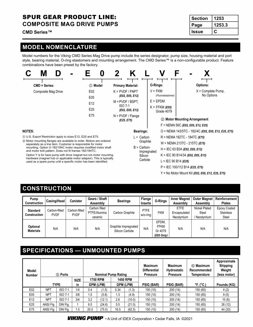
PSIG (BAR) PSIG (BAR) °F. (°C.) Pounds (KG)GPM (LPM) GPM (LPM)E02 NPT ISO 7-1 1/4 0.4 (1.5) 0.34 (1.3) 150 (10) 200 (14) 150 (65) 4 (2)E05 NPT ISO 7-1 3/8 1.5 (5.8) 1.3 (4.9) 150 (10) 200 (14) 150 (65) 9 (5)E12 NPT ISO 7-1 3/4 3.2 (12.1) 2.6 (10.0) 150 (10) 200 (14) 150 (65) 10 (6)E25 ANSI Flg DIN Flg. 1 6.5 (24.6) 5.5 (21.0) 150 (10) 200 (14) 150 (65) 26 (12)E75 ANSI Flg DIN Flg. 1.5 20.0 (75.0) 16.5 (62.5) 150 (10) 200 (14) 150 (65) 44 (20)
CMD = Series:Composite Mag Drive
① ModelE02E05E12E25E75
② Motor Mounting ArrangementF = NEMA 56C (E02, E05, E12, E25)
O = NEMA 143/5TC - 182/4C (E02, E05, E12, E25, E75)
R = NEMA 182TC - 184TC (E75)
W = NEMA 213TC - 215TC (E75)
H = IEC 63 B34 (E02, E05, E12)
K = IEC 80 B14/34 (E02, E05, E12)
L = IEC 90 B14 (E25)
P = IEC 100/112 B14 (E25, E75)
Y = No Motor Mount Kit (E02, E05, E12, E25, E75)
C M D - E 0 2 K L V F - XOptions: X = Complete Pump,
No Options
Primary Material:K = PVDF / FNPT
(E02, E05, E12)
M = PVDF / BSPT, ISO 7-1 (E02, E05, E12)
N = PVDF / Flange (E25, E75)
Bearings:L = Carbon
GraphiteB = Carbon-
Impregnated Silicon Carbide
O-Rings:V = FKM
(Fluoroelastomer)
E = EPDMK = FFKM (E05)
Grade 4079
MODEL NOMENCLATUREModel numbers for the Viking CMD Series Mag Drive pump include the series designator, pump size, housing material and port style, bearing material, O-ring elastomers and mounting arrangement. The CMD Series™ is a non-configurable product. Feature combinations have been preset by the factory.
NOTES:① U.S. Export Restriction apply to sizes E12, E25 and E75.② Motor mounting flanges are available to order. Motors are ordered
separately as a line item. Customer is responsible for motor mounting. Option O 182/184C motor requires modified motor shaft and motor bolt pattern. Does not fit frames 182/184TC.
Option Y is for bare pump with drive magnet but not motor mounting hardware (magnet hub or applicable motor adaptor). This is typically used as a spare pump until a specific motor has been identified.
Section 1253Page 1253.3Issue CCMD Series™
SPUR GEAR PRODUCT LINE: COMPOSITE MAG DRIVE PUMPS
• A Unit of IDEX Corporation • Cedar Falls, IA ©2021
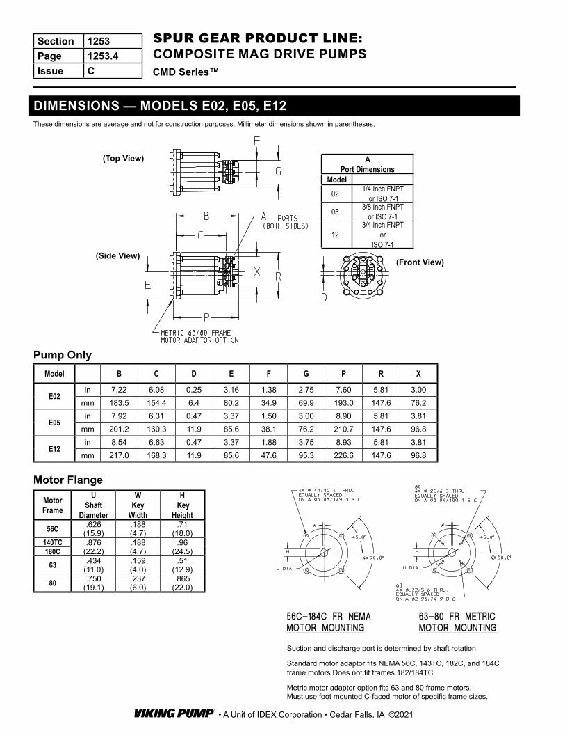
DIMENSIONS — MODELS E02, E05, E12These dimensions are average and not for construction purposes. Millimeter dimensions shown in parentheses.
Suction and discharge port is determined by shaft rotation.
Standard motor adaptor fits NEMA 56C, 143TC, 182C, and 184C frame motors Does not fit frames 182/184TC.
Metric motor adaptor option fits 63 and 80 frame motors.Must use foot mounted C-faced motor of specific frame sizes.
Model B C D E F G P R X
E02in 7.22 6.08 0.25 3.16 1.38 2.75 7.60 5.81 3.00
mm 183.5 154.4 6.4 80.2 34.9 69.9 193.0 147.6 76.2
E05in 7.92 6.31 0.47 3.37 1.50 3.00 8.90 5.81 3.81
mm 201.2 160.3 11.9 85.6 38.1 76.2 210.7 147.6 96.8
E12in 8.54 6.63 0.47 3.37 1.88 3.75 8.93 5.81 3.81
mm 217.0 168.3 11.9 85.6 47.6 95.3 226.6 147.6 96.8
Motor Flange
A Port Dimensions
Model02 1/4 Inch FNPT
or ISO 7-105 3/8 Inch FNPT
or ISO 7-1
123/4 Inch FNPT
orISO 7-1
Pump Only
(Top View)
(Side View)(Front View)
MotorFrame
UShaft
Diameter
WKey
Width
H Key
Height56C .626
(15.9).188(4.7)
.71(18.0)
140TC .876(22.2)
.188(4.7)
.96(24.5)180C
63 .434(11.0)
.159(4.0)
.51(12.9)
80 .750(19.1)
.237(6.0)
.865(22.0)
Section 1253Page 1253.4Issue C CMD Series™
SPUR GEAR PRODUCT LINE: COMPOSITE MAG DRIVE PUMPS
• A Unit of IDEX Corporation • Cedar Falls, IA ©2021
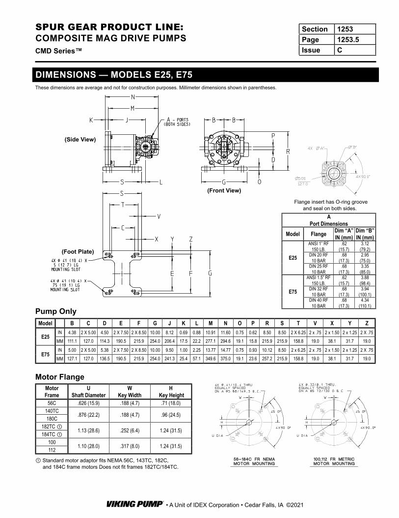
Model B C D E F G J K L M N O P R S T V X Y Z
E25IN 4.38 2 X 5.00 4.50 2 X 7.50 2 X 8.50 10.00 8.12 0.69 0.88 10.91 11.60 0.75 0.62 8.50 8.50 2 X 6.25 2 x .75 2 x 1.50 2 x 1.25 2 X .75
MM 111.1 127.0 114.3 190.5 215.9 254.0 206.4 17.5 22.2 277.1 294.6 19.1 15.8 215.9 215.9 158.8 19.0 38.1 31.7 19.0
E75IN 5.00 2 X 5.00 5.38 2 X 7.50 2 X 8.50 10.00 9.50 1.00 2.25 13.77 14.77 0.75 0.93 10.12 8.50 2 x 6.25 2 x .75 2 x 1.50 2 x 1.25 2 X .75
MM 127.1 127.0 136.5 190.5 215.9 254.0 241.3 25.4 57.1 349.6 375.0 19.1 23.6 257.2 215.9 158.8 19.0 38.1 31.7 19.0
MotorFrame
UShaft Diameter
WKey Width
H Key Height
56C .626 (15.9) .188 (4.7) .71 (18.0)140TC
.876 (22.2) .188 (4.7) .96 (24.5)180C
182TC ①1.13 (28.6) .252 (6.4) 1.24 (31.5)
184TC ①100
1.10 (28.0) .317 (8.0) 1.24 (31.5)112
A Port Dimensions
Model Flange Dim “A”IN (mm)
Dim “B” IN (mm)
E25
ANSI 1” RF 150 LB.
.62 (15.7)
3.12 (79.2)
DIN 20 RF 10 BAR
.68 (17.3)
2.95 (75.0)
DIN 25 RF 10 BAR
.68 (17.3)
3.35 (85.0)
E75
ANSI 1.5” RF 150 LB.
.62 (15.7)
3.88 (98.4)
DIN 32 RF 10 BAR
.68 (17.3)
3.94 (100.1)
DIN 40 RF 10 BAR
.68 (17.3)
4.34 (110.1)
Motor Flange
Pump Only
DIMENSIONS — MODELS E25, E75These dimensions are average and not for construction purposes. Millimeter dimensions shown in parentheses.
(Side View)
(Front View)
(Foot Plate)
Flange insert has O-ring groove and seal on both sides.
① Standard motor adaptor fits NEMA 56C, 143TC, 182C, and 184C frame motors Does not fit frames 182TC/184TC.
Section 1253Page 1253.5Issue CCMD Series™
SPUR GEAR PRODUCT LINE: COMPOSITE MAG DRIVE PUMPS
• A Unit of IDEX Corporation • Cedar Falls, IA ©2021

SERIES CMD PUMP MODEL STRINGThis table is used to develop the model number code for the features and mounting required.
Available Model Code Description CMD- E _ _ _ _ _ _ _ - _
POSITIONS 1,2,3
CMD
E02 SIZE E02 - MAX. CAPACITY 0.4 GPM (1.5 LPM) 1/4”-18 FNPT / 1/4”-19 BSPT, ISO 7-1
PUMP SIZE
E05 SIZE E05 - MAX. CAPACITY 1.3 GPM (4.9 LPM) 3/8”-18 FNPT / 3/8”-19 BSPT, ISO 7-1
E12 SIZE E12 - MAX. CAPACITY 3.2 GPM (12.1 LPM) 3/4”-14 FNPT / 3/4”-14 BSPT, ISO 7-1
E25 SIZE E25 - MAX. CAPACITY 6.5 GPM (24.6 LPM) FLANGED 1”-150 ANSI / DIN 20/25
E75 SIZE E75 - MAX. CAPACITY 20.0 GPM (75.0 LPM) FLANGED 1 1/2”-150# ANSI / DIN 32/40
POSITION 4 02,05 K CARBON-FILLED PVDF, FNPT
PRIMARYMATERIAL
02,05 M CARBON-FILLED PVDF, BSPT, ISO 7-1
Export Restrictions May Apply to the following sizes listed below
12 K CARBON-FILLED PVDF, FNPT
12 M CARBON-FILLED PVDF, BSPT, ISO 7-1
25,75 N CARBON-FILLED PVDF, FLANGED
POSITION 502,05,12,25,75
L CARBON
BEARINGS B SILICON CARBIDE
POSITION 6 02,05,12,25,75 V FLUOROELASTOMER (FKM)
O-RINGS02,05,12,25,75 E EPDM
05 K FFKM Grade 4079
POSITION 7 02,05,12,25 F NEMA 56C (C-face, rigid base, 5/8” shaft diameter, 4x 3/8”-16 tapped holes on a 5-7/8” bolt circle)
MOTORMOUNTING
ARRANGEMENTS
02,05,12,25,75 O NEMA 143/5TC-182/4C (C-face, rigid base, 7/8” shaft diameter, 4x 3/8”-16 tapped holes on a 5-7/8” bolt circle)
75 R NEMA 182TC-184TC (C-face, rigid base, 1-1/8” shaft diameter, 4x 1/2”-13 tapped holes on a 7-1/4” bolt circle)
75 W NEMA 213TC-215TC (C-face, rigid base, 1-3/8” shaft diameter, 4x 1/2”-13 tapped holes on a 7-1/4” bolt circle)
02,05,12 H IEC 63 B3/B14 (rigid base, face, 11 mm motor shaft diameter, 4x M5 tapped holes on a 75 mm bolt circle)
02,05,12 K IEC 80 B3/B14 (rigid base, face, 19 mm motor shaft diameter, 4x M6 tapped holes on a 100 mm bolt circle)
25 L IEC 90 B3/B14 (rigid base, face, 24 mm motor shaft diameter, 4x M8 tapped holes on a 115 mm bolt circle)
25,75 P IEC 100/112 B3/B14 (rigid base, face, 28 mm motor shaft diameter, 4x M8 tapped holes on a 130 mm bolt circle)
02,05,12,25,75 Y NO MOTOR MOUNTING KIT (Pump includes Drive Magnet)
POSITION 8 02,05,12,25,75 – DASH
POSITION 9 02,05,12,25,75 X STANDARD (COMPLETE PUMP - NO OPTIONS)
Section 1253Page 1253.6Issue C CMD Series™
SPUR GEAR PRODUCT LINE: COMPOSITE MAG DRIVE PUMPS
• A Unit of IDEX Corporation • Cedar Falls, IA ©2021

RELIEF VALVE INFORMATIONThe CMD series pump is a positive displacement pump and requires some sort of over pressure protection, however, an internal relief valve is not provided as standard with this series.
Optional third party adjustable spring loaded diaphragm in-line pressure relief valves, constructed of either PVC or PVDF, are available in two or three port configurations. These in-line
valves are easily set in the field for system pressures ranging between 0 - 150 PSI. Vendor recommendation is to set the pressure valve at 15 PSI above the system pressure. This pressure relief valve should be placed as close to the pump as possible without any other valves or accessories placed between the pump and relief valve.
D A B (in) C (in) Ports PN - PVC Construction
PN - PVDF Construction Notes
1/2” 5.5 3.5 1.125 NPT W777267-PVC W777267-KYN 3rd bottom port option is piped as a return-to-tank line.1” 5.8 3.5 1.25 NPT W777259-PVC W777259-KYN 3rd bottom port option is piped as a return-to-tank line.
1-1/2” 90 5.5 2.25 NPT W777260-PVC W777260-KYN 2 port straight line configuration, Discharge line would require a tee off. Line must be back to the tank.
DIMENSIONS:
A
C
B
D
O nly o n 3 PortPre ssure Re lief Va lve
DIMENSIONS:
A
C
B
D
TYPICAL PIPING EXAMPLES
Two-Port Valve Arrangement Three-Port Valve Arrangement
DIMENSIONSThree port Pressure Relief Valve
3 Port Pressure Relief Valve
Inlet or Discharge
Relief Line (Return to Tank)
Inlet or Discharge
Relief Line (Return To Tank)
Inlet or
Discharge
Inlet or
Discharge
Two port Pressure Relief Valve
2 Port Pressure Relief Valve
InletDischarge
DischargeInlet
Section 1253Page 1253.7Issue CCMD Series™
SPUR GEAR PRODUCT LINE: COMPOSITE MAG DRIVE PUMPS
• A Unit of IDEX Corporation • Cedar Falls, IA ©2021

Liquid List
Key: “A” Excellent “C” Questionable “X” Not RecommendedWetted Parts
PrimaryMaterial Shaft Gears Bearings & Wear Plates O-Rings
PVDF Alumina Ceramic PTFE Carbon
Graphite
Silicon Carbide (Option)
Fluoroelastomer (FKM)
EPDM (Option) FFKM
Acetaldehyde X A A A X A AAcetamide C A A A A A A
Acetic Acid (Glacial) A A A A A X A AAcetic Acid, Dilute (50% H2O) A A A A A X A A
Acetone X A A A A X A AAcetonitrile A A A X A A
Acetylene Tetrachloride A A A X X AAcrylonitrile 22°C A A A X X AAdipic Acid 66°C A A A X X A
Allyl Chloride A A A X X AAlum (Aluminum Ammonium Sulfate) -- A A A A A A
Aluminum Chloride A A A A A A A AAluminum Fluoride A A A A A A A
Aluminum Hydroxide A A A A X A AAluminum Nitrate 48°C A A A A A A
Aluminum Potassium Sulfate A A A A A AAmmonia (Anhydrous) X A A A X A A
Ammonia (Aqueous 30%) X A A A A X A AAmmonium Chloride A A A A A A A AAmmonium Fluoride A A A A A A
Ammonium Hydroxide A A A A A A A AAmmonium Sulfate A A A A A X A AAmmonium Sulfide 52°C A A A X A A
Aniline 38°C A A A A X A AAnthraquinone A A A A A A
Barium Chloride A A A A A A A ABarium Hydroxide A A A A A A A A
Barium Sulfate A A A A A A A ABarium Sulfide A A A A A A A A
Benzene 48°C A A A A A X ABenzene Sulfonic Acid A A A A A X A
Benzoic Acid A A A A A A X ABenzyl Alcohol A A A A A A ABenzyl Chloride A A A X A
Borax A A A X A A A ABoric Acid A A A A A A A A
Brine A X A A A ABromic Acid A X A X X A
Bromine (Dry) A A A X A A X AButadiene A A A A A A A A
Butane A A A A A A X AButanediol A A A A A A
n-Butyl Alcohol A A A A A A AButyl Bromide A X A A X AButyl Chloride A A A A X AButyl Phenol A A A A A A
Calcium Bisulfate A A A A ACalcium Bisulfide A A A A A A A
Calcium Carbonate A A A A A A A ACalcium Chlorate A A A X A A A ACalcium Chloride A A A A A A A A
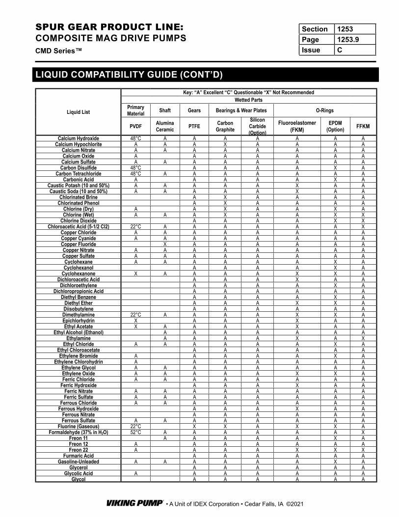
LIQUID COMPATIBILITY GUIDEThis list is intended as a general guide. The liquid compatibility of materials and elastomers has been compiled from many sources. Although the sources are believed reliable, the rating cannot be guaranteed. In any given case many factors such as concentration, temperature and the presence of impurities or trace elements may influence material performance.
For additional information, consult the CMD series pump selection software. For specific questions, contact the factory for assistance.
Section 1253Page 1253.8Issue C CMD Series™
SPUR GEAR PRODUCT LINE: COMPOSITE MAG DRIVE PUMPS
• A Unit of IDEX Corporation • Cedar Falls, IA ©2021
Liquid List
Key: “A” Excellent “C” Questionable “X” Not RecommendedWetted Parts
PrimaryMaterial Shaft Gears Bearings & Wear Plates O-Rings
PVDF Alumina Ceramic PTFE Carbon
GraphiteSilicon Carbide (Option)
Fluoroelastomer (FKM)
EPDM (Option) FFKM
Calcium Hydroxide 48°C A A A A A A ACalcium Hypochlorite A A A X A A A A
Calcium Nitrate A A A A A A A ACalcium Oxide A A A A A A ACalcium Sulfate A A A A A A A ACarbon Disulfide 48°C A A A A X A
Carbon Tetrachloride 48°C A A A A A A ACarbonic Acid A A A A A X A
Caustic Potash (10 and 50%) A A A A A X A ACaustic Soda (10 and 50%) A A A A A X A A
Chlorinated Brine A X A A A AChlorinated Phenol A X A A A A
Chlorine (Dry) A A X A A X AChlorine (Wet) A A A X A A X X
Chlorine Dioxide A A A A X XChloroacetic Acid (5-1/2 Cl2) 22°C A A A A A A X
Copper Chloride A A A A A A A ACopper Cyanide A A A A A A A ACopper Fluoride X A A A A A ACopper Nitrate A A A A A A A ACopper Sulfate A A A A A A A ACyclohexane A A A A A A X ACyclohexanol A A A A X A
Cyclohexanone X A A A A X X ADichloroacetic Acid A A A X A A
Dichloroethylene A A A A X ADichloropropionic Acid A A A A A A
Diethyl Benzene A A A A X ADiethyl Ether A A A X X ADiisobutylene A A A A A A
Dimethylamine 22°C A A A A X X AEpichlorhydrin X A A A X A AEthyl Acetate X A A A A X A A
Ethyl Alcohol (Ethanol) A A A A A A AEthylamine A A A A X A X
Ethyl Chloride A A A A A A X AEthyl Chloroacetate A A A A A AEthylene Bromide A A A A A X A
Ethylene Chlorohydrin A A A A A A AEthylene Glycol A A A A A A A AEthylene Oxide A A A A A X X AFerric Chloride A A A A A A A A
Ferric Hydroxide A A A X A AFerric Nitrate A A A A A A A AFerric Sulfate A A A A A A A A
Ferrous Chloride A A A A A A A AFerrous Hydroxide A A A X A A
Ferrous Nitrate A A A A A AFerrous Sulfate A A A A A A A A
Fluorine (Gaseous) 22°C X X A X X AFormaldehyde (37% in H2O) 52°C A A A A A A X
Freon 11 A A A A A X AFreon 12 A A A A A A AFreon 22 A A A A X X X
Furmaric Acid A A A A A AGasoline-Unleaded A A A A A A X A
Glycerol A A A A A AGlycolic Acid A A A A A A A
Glycol A A A A A A
LIQUID COMPATIBILITY GUIDE (CONT’D)
Section 1253Page 1253.9Issue CCMD Series™
SPUR GEAR PRODUCT LINE: COMPOSITE MAG DRIVE PUMPS
• A Unit of IDEX Corporation • Cedar Falls, IA ©2021
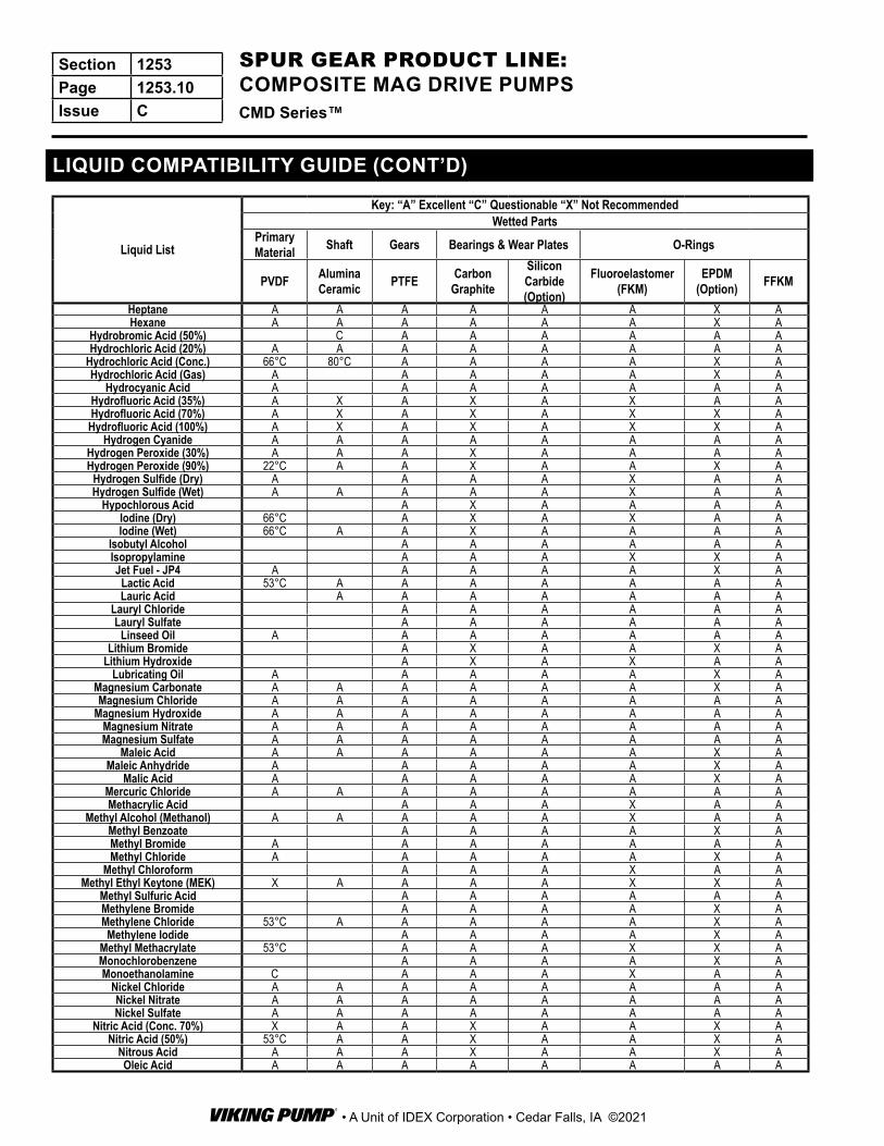
LIQUID COMPATIBILITY GUIDE (CONT’D)
Liquid List
Key: “A” Excellent “C” Questionable “X” Not RecommendedWetted Parts
PrimaryMaterial Shaft Gears Bearings & Wear Plates O-Rings
PVDF Alumina Ceramic PTFE Carbon
Graphite
Silicon Carbide (Option)
Fluoroelastomer (FKM)
EPDM (Option) FFKM
Heptane A A A A A A X AHexane A A A A A A X A
Hydrobromic Acid (50%) C A A A A A AHydrochloric Acid (20%) A A A A A A A A
Hydrochloric Acid (Conc.) 66°C 80°C A A A A X AHydrochloric Acid (Gas) A A A A A X A
Hydrocyanic Acid A A A A A A AHydrofluoric Acid (35%) A X A X A X A AHydrofluoric Acid (70%) A X A X A X X A
Hydrofluoric Acid (100%) A X A X A X X AHydrogen Cyanide A A A A A A A A
Hydrogen Peroxide (30%) A A A X A A A AHydrogen Peroxide (90%) 22°C A A X A A X A
Hydrogen Sulfide (Dry) A A A A X A AHydrogen Sulfide (Wet) A A A A A X A A
Hypochlorous Acid A X A A A AIodine (Dry) 66°C A X A X A AIodine (Wet) 66°C A A X A A A A
Isobutyl Alcohol A A A A A AIsopropylamine A A A X X AJet Fuel - JP4 A A A A A X A
Lactic Acid 53°C A A A A A A ALauric Acid A A A A A A A
Lauryl Chloride A A A A A ALauryl Sulfate A A A A A A
Linseed Oil A A A A A A ALithium Bromide A X A A X A
Lithium Hydroxide A X A X A ALubricating Oil A A A A A X A
Magnesium Carbonate A A A A A A X AMagnesium Chloride A A A A A A A A
Magnesium Hydroxide A A A A A A A AMagnesium Nitrate A A A A A A A AMagnesium Sulfate A A A A A A A A
Maleic Acid A A A A A A X AMaleic Anhydride A A A A A X A
Malic Acid A A A A A X AMercuric Chloride A A A A A A A AMethacrylic Acid A A A X A A
Methyl Alcohol (Methanol) A A A A A X A AMethyl Benzoate A A A A X AMethyl Bromide A A A A A A AMethyl Chloride A A A A A X A
Methyl Chloroform A A A X A AMethyl Ethyl Keytone (MEK) X A A A A X X A
Methyl Sulfuric Acid A A A A A AMethylene Bromide A A A A X AMethylene Chloride 53°C A A A A A X A
Methylene Iodide A A A A X AMethyl Methacrylate 53°C A A A X X AMonochlorobenzene A A A A X AMonoethanolamine C A A A X A A
Nickel Chloride A A A A A A A ANickel Nitrate A A A A A A A ANickel Sulfate A A A A A A A A
Nitric Acid (Conc. 70%) X A A X A A X ANitric Acid (50%) 53°C A A X A A X A
Nitrous Acid A A A X A A X AOleic Acid A A A A A A A A
Section 1253Page 1253.10Issue C CMD Series™
SPUR GEAR PRODUCT LINE: COMPOSITE MAG DRIVE PUMPS
• A Unit of IDEX Corporation • Cedar Falls, IA ©2021
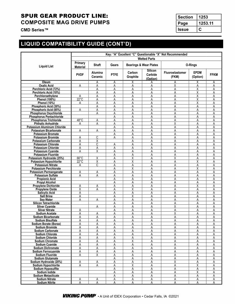
LIQUID COMPATIBILITY GUIDE (CONT’D)
Liquid List
Key: “A” Excellent “C” Questionable “X” Not RecommendedWetted Parts
PrimaryMaterial Shaft Gears Bearings & Wear Plates O-Rings
PVDF Alumina Ceramic PTFE Carbon
Graphite
Silicon Carbide (Option)
Fluoroelastomer (FKM)
EPDM (Option) FFKM
Oleum A A X A A X AOxalic Acid A A A A A X A A
Perchloric Acid (72%) A A A A A X APerchloric Acid (10%) A A A A A X A
Perchloroethylene A A A A A A X APhenol (100%) 22°C A A A A A X APhenol (10%) A A A A A A X A
Phosphoric Acid (30%) A A A A A A APhosphoric Acid (85%) A A A A A A A A
Phosphorus Oxychloride A A A A A A APhosphorus Pentachloride A A A A A A
Phosphorus Trichloride 48°C A A A A A A APhthalic Anhydride A A A A A X A A
Potassium Aluminum Chloride A A A A A APotassium Bicarbonate A A A A A A A A
Potassium Bromate A A A A A APotassium Bromide A C A A A A A A
Potassium Carbonate A X A A A A APotassium Chlorate A C A A A A A APotassium Chloride A A A A A A A APotassium Cyanide A X A A A A A APotassium Fluoride A A A A A A
Potassium Hydroxide (25%) 66°C X A X A X A APotassium Hypochlorite 22°C X A X A A X A
Potassium Nitrate A C A A A A A APotassium Perchlorate A X A A X A
Potassium Permanganate A A A A A A A APotassium Sulfate A A A A A A A A
Propionic Acid A A A A A APropyl Alcohol A A A A A A
Propylene Dichloride A A A A A A X APropylene Oxide X A A X A A A A
Salicylic Acid A A A A A A ASalt Brine A A X A A A ASea Water A A A A A A A A
Silicon Tetrachloride A A A A A ASilver Cyanide A A A A X A ASilver Nitrate A A A A A A A
Sodium Acetate A A A A A X A ASodium Bicarbonate A A A A A A A A
Sodium Bisulfate A A A A A A A ASodium Borate (Borax) A A A A A A A A
Sodium Bromide A A A A A A A ASodium Carbonate A A A A A A A ASodium Chlorate A A A A A A A ASodium Chloride A A A A A A A A
Sodium Chromate A A A X A A A ASodium Cyanide A A A A A A A A
Sodium Dichromate A A A A A A A ASodium Ferrocyanide A A A A A A A A
Sodium Fluoride A X A A A A A ASodium Glutamate A A A A A A
Sodium Hydroxide (20%) A A A A A X A ASodium Hypochlorite A A A X A A X ASodium Hyposulfite A A A A A A
Sodium Iodide A A A A X ASodium Metasilicate A A A A A A
Sodium Nitrate A A A A A A A ASodium Nitrite A A A A A A A A
Section 1253Page 1253.11Issue CCMD Series™
SPUR GEAR PRODUCT LINE: COMPOSITE MAG DRIVE PUMPS
• A Unit of IDEX Corporation • Cedar Falls, IA ©2021

LIQUID COMPATIBILITY GUIDE (CONT’D)
Liquid List
Key: “A” Excellent “C” Questionable “X” Not RecommendedWetted Parts
PrimaryMaterial Shaft Gears Bearings & Wear Plates O-Rings
PVDF Alumina Ceramic PTFE Carbon
Graphite
Silicon Carbide (Option)
Fluoroelastomer (FKM)
EPDM (Option) FFKM
Sodium Perchlorate A A A A A ASodium Peroxide A A A X A A A A
Sodium Persulfate A A A A A ASodium Phosphate A A A A A A A A
Sodium Silicate A A A A A A A ASodium Sulfate A A A A A A A ASodium Sulfide A A A A A A A ASodium Sulfite A A A A A A A A
Sodium Thiosulfate A A A A A A A AStannous Chloride A A A A A A A AStannous Fluoride A X A A A A
Stearic Acid A A A A A A A AStyrene Monomer A A A A X A
Succinic Acid A A A X X ASulfamic Acid A X A A X ASulfur (Molten) A X A A X ASulfur Dioxide A A A X A A A A
Sulfuric Acid (60%) 66°C A A A A A A ASulfuric Acid (Conc.) 66°C A A A A A X A
Sulfuric Acid (Fuming-Oleum) X A X A A X ASulfurous Acid A A A A A A X A
Tannic Acid A A A A A A X ATartaric Acid A A A A A A A A
Tetrahydrofuran 22°C A A A A X X AThionyl Chloride A A A A X ATin Tetrachloride A X A A X A
Titanium Tetrachloride A A A A X XToluene 79°C A A A A A X A
Tributyl Phosphate C A A A A X X ATrichloroacetic Acid A A A A A A A
Trichloroethylene A A A A A A X ATrichloromethane A A A A X A
Triethylamine 48°C A A A A A A ATrioxane A A A X X X
Turpentine A A A A A A X AUrea (50% H2O) A C A A A X X A
Vinyl Acetate A C A A A X X AVinyl Chloride (Monomer) 22°C A A A A A X A
Water A A A A A A A AWax (Paraffin) A A A A X A
Xylene A A A A A A X AZinc Acetate A A A X A AZinc Chloride A C A A A A A A
Zinc Hydrosulfite (10%) A A A A A AZinc Nitrate A A A A A AZinc Sulfide A A A A A AZinc Sulfate A C A A A A A A
ETFE = Ethylene TetrafluoroethylenePVDF = Polyvinylidene Fluroide
Section 1253Page 1253.12Issue C CMD Series™
SPUR GEAR PRODUCT LINE: COMPOSITE MAG DRIVE PUMPS
• A Unit of IDEX Corporation • Cedar Falls, IA ©2021
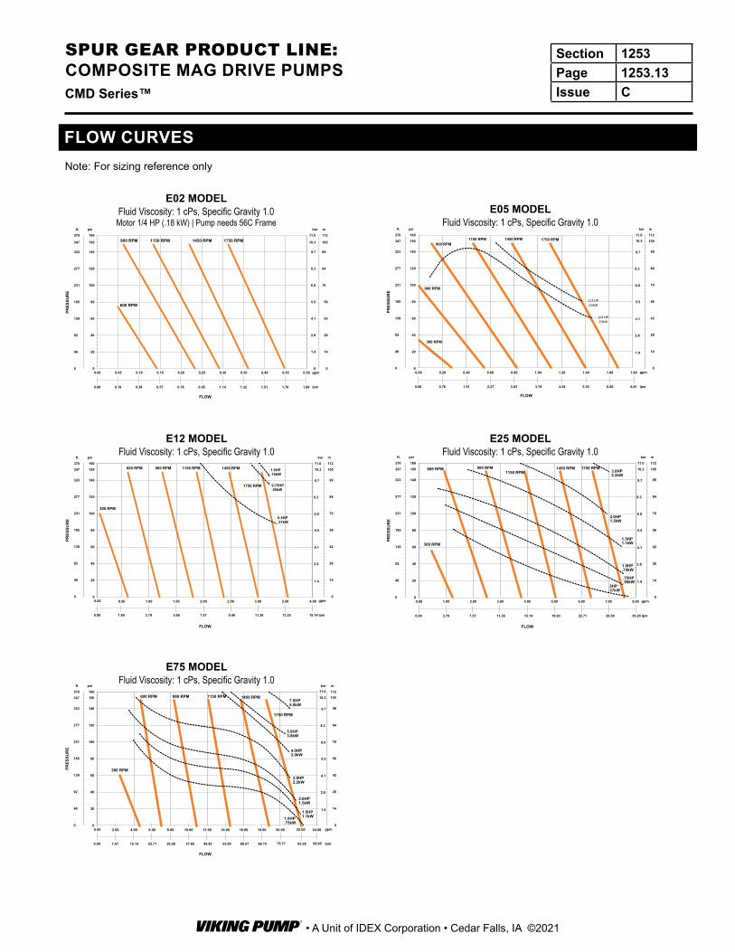
FLOW CURVESNote: For sizing reference only
E02 MODELFluid Viscosity: 1 cPs, Specific Gravity 1.0Motor 1/4 HP (.18 kW) | Pump needs 56C Frame
E12 MODELFluid Viscosity: 1 cPs, Specific Gravity 1.0
E75 MODELFluid Viscosity: 1 cPs, Specific Gravity 1.0
E05 MODELFluid Viscosity: 1 cPs, Specific Gravity 1.0
0
20
40
60
80
100
120
140
160
0.00 0.05 0.10 0.15 0.20 0.25 0.30 0.35 0.40 0.45 0.50
PRES
SUR
E
FLOW
1750 RPM1450 RPM1150 RPM900 RPM
600 RPM
0
1.4
2.8
4.1
5.5
6.9
8.3
9.7
11.0
0
46
92
139
185
231
277
323
370
0
14
28
42
56
70
84
99
112
0.00 0.19 0.38 0.57 0.76 0.95 1.14 1.32 1.51 1.70 1.89
ft. psi bar m
gpm
lpm
150347 10.3 105
PRES
SUR
E
FLOW
0
46
92
139
185
231
277
323
370
0
14
28
42
56
70
84
99
112
0.00 0.76 1.51 2.27 3.03 3.79 4.54 5.30 6.06 6.81
ft. psi bar m
gpm
lpm
0
20
40
60
80
100
120
140
160
0.00 0.20 0.40 0.60 0.80 1.00 1.20 1.40 1.60 1.80
9.7
8.3
6.9
5.5
4.1
2.8
1.4
347 150 10510.311.0
300 RPM
1750 RPM1450 RPM1150 RPM900 RPM
600 RPM
1/4 HP.19kW
1/3 HP.23kW
E25 MODELFluid Viscosity: 1 cPs, Specific Gravity 1.0
PRES
SUR
E
FLOW
0
46
92
139
185
231
277
323
370
0
14
28
42
56
70
84
99
112
0.00 1.89 3.79 5.68 7.57 9.46 11.36 13.25 15.14
ft. psi bar m
gpm
lpm
0
20
40
60
80
100
120
140
160
0.00
9.7
8.3
6.9
5.5
4.1
2.8
1.4
0.50 1.00 1.50 2.00 2.50 3.00 3.50 4.00
300 RPM
600 RPM 900 RPM 1150 RPM 1450 RPM
1750 RPM
1.0HP.75kW
0.75HP.55kW
0.5HP.37kW
347 150 10510.311.0
PRES
SUR
E
FLOW
0
46
92
139
185
231
277
323
370
0
14
28
42
56
70
84
99
112
0.00 3.79 7.57 11.36 15.14 18.93 22.71 26.50 30.28
ft. psi bar m
gpm
lpm
0
20
40
60
80
100
120
140
160
0.00
9.7
8.3
6.9
5.5
4.1
2.8
1.4
900 RPM
1.00 2.00 3.00 4.00 5.00 6.00 7.00 8.00
300 RPM
1750 RPM1450 RPM1150 RPM
600 RPM
2.0HP1.5kW
1.5HP1.1kW
1.0HP.75kW
.75HP
.55kW.5HP.37kW
3.0HP2.2kW
347 150 10510.311.0
PRES
SUR
E
FLOW
0
46
92
139
185
231
277
323
370
0
14
28
42
56
70
84
99
112
0.00 7.57 15.14 22.71 30.28 37.85 45.42 53.00 60.57
ft. psi bar m
gpm
lpm
0
20
40
60
80
100
120
140
160
0.00 4.00 8.00 12.00 16.00 20.00 24.00
300 RPM
1750 RPM
1450 RPM1150 RPM900 RPM600 RPM
1.0HP.75kW
2.0HP1.5kW
1.5HP1.1kW
3.0HP2.2kW
4.0HP3.0kW
5.0HP3.8kW
7.5HP5.5kW
9.7
8.3
6.9
5.5
4.1
2.8
1.4
2.00 6.00 10.00 14.00 18.00 22.00
68.14 75.71 83.28 90.85
347 150 10510.311.0
Section 1253Page 1253.13Issue CCMD Series™
SPUR GEAR PRODUCT LINE: COMPOSITE MAG DRIVE PUMPS
• A Unit of IDEX Corporation • Cedar Falls, IA ©2021


![1 Спорт · 2020-06-05 · «Нижегородский спорт» № 48 (1253) 11 декабря 2019 1 СпортНижегородский №48 [1253] следующий](https://img.pdfslide.net/doc/110x75/5fb088e63b180b0c0526d3de/1-2020-06-05-a-48-1253.jpg)