Embed Size (px)
Citation preview
RR
Thank you for purchasing a Futaba 6YG. Before using your 6YG, read this manual carefully and use your R/C setsafely. After reading this manual, store it in a safe place.
See the glossary page 22 for a definition of the special terms used in this manual.
APPLICATION, EXPORT, AND RECONSTRUCTION
1. This product may be used for model airplane or surface use if on the correct frequency.
2. Exportation precautions (a) When this product is exported from Japan, its use is to be approved by the Radio Law of the country ofdestination. (b) Use of this product with other than models may be restricted by Export and Trade Control Regulations. Anapplication for export approval must be submitted.
3. Modification, adjustment, and replacement of parts Futaba is not responsible for unauthorized modification, adjustment, and replacement of parts of this product.
The Following Statement Applies to the Receiver (for U.S.A.)
This device complies with part 15 of the FCC rules. Operation is subject to the following two conditions:
(1) This device may not cause harmful interference, and(2) This device must accept any interference received, including interference that may cause undesired operation.
•No part of this manual may be reproduced in any form without prior permission. •The contents of this manual are subject to change without prior notice.•This manual has been carefully written. Please write to Futaba if you feel that any corrections or clarifications should be made.•Futaba is not responsible for the misuse of this product.
CONTENTS-2-

SAFETY INFORMATION....................................................4
Meaning of Special Markings ....................................................4
Precautions During Flight ..........................................................4
NiCd Battery Charging Precautions ............................................6
Storage and Disposal Precautions ..............................................7
Other Precautions ........................................................................8
BEFORE USE ....................................................................9
Set Contents ................................................................................9
Name and Handling of Each Part................................................10
Transmitter Operation and Movement of Each Servo ................14
INSTALLATION AND ADJUSTMENT ................................15
Connections ................................................................................15
Adjustments ................................................................................17
USING OTHER FUNCTIONS ............................................18
Aileron/Elevator Dual Rate (D/R) Function ..............................18
Non-slip Adjustable Lever Head ................................................18
Stick Lever Spring Tension Adjustment ....................................19
Trainer Function ..........................................................................19
REFERENCE......................................................................20
Ratings ........................................................................................20
Troubleshooting ..........................................................................21
Glossary ......................................................................................22
Repair Service ............................................................................23
-3-

SAFETY INFORMATIONTo ensure safe use, observe the following precautions.
Meaning of Special Markings Pay special attention to safety at the parts of this manual that are indicated by the following marks.
Mark Meaning
Procedures which may lead to a dangerous condition and cause death or serious injury tothe user if not carried out properly.
Procedures which may lead to a dangerous condition or cause death or serious injury to theuser if not carried out properly, or procedures where the probability of superficial injury orphysical damage is high.
Procedures where the possibility of serious injury to the user is small, but there is a dangerof injury, or physical damage, if not carried out properly.
Symbol:
Prohibited Mandatory
Precautions During Flight
Do not fly or turn "On" simultaneously on the same frequency.
Interference will cause a crash.
Use of the same frequency will cause interference even if the
modulation method (AM, FM, PCM) is different.
Do not fly on rainy or windy days, or at night.
Water will penetrate into the transmitter (Tx) and cause faulty
operation, or loss of control, and cause a crash.
-4-
Do not fly in the following places:
-Near other R/C flying fields (within about 2.5miles [3km]
-Near people on the ground, or objects in the air
-Near homes, schools, hospitals, or other places where there are a lot of people
-Near high tension lines, high structures, or communication facilities
Radiowave interference and obstructions may cause a crash. A crash caused by trouble in the R/C set, or the modelitself, may cause death or property damage.
Do not fly when you are tired, sick, or intoxicated.
Fatigue, illness, or intoxication will cause a loss of concentration or normal judgment and result in operation errors and acrash.
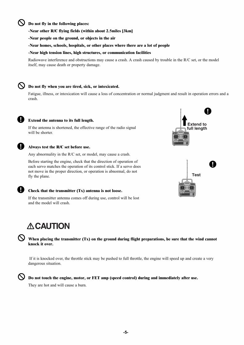
Extend the antenna to its full length.
If the antenna is shortened, the effective range of the radio signalwill be shorter.
Always test the R/C set before use.
Any abnormality in the R/C set, or model, may cause a crash.
Before starting the engine, check that the direction of operation ofeach servo matches the operation of its control stick. If a servo doesnot move in the proper direction, or operation is abnormal, do notfly the plane.
Check that the transmitter (Tx) antenna is not loose.
If the transmitter antenna comes off during use, control will be lostand the model will crash.
When placing the transmitter (Tx) on the ground during flight preparations, be sure that the wind cannotknock it over.
If it is knocked over, the throttle stick may be pushed to full throttle, the engine will speed up and create a verydangerous situation.
Do not touch the engine, motor, or FET amp (speed control) during and immediately after use.
They are hot and will cause a burn.
-5-
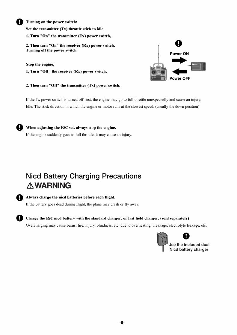
Turning on the power switch:
Set the transmitter (Tx) throttle stick to idle.
1. Turn "On" the transmitter (Tx) power switch,
2. Then turn "On" the receiver (Rx) power switch. Turning off the power switch:
Stop the engine,
1. Turn "Off" the receiver (Rx) power switch,
2. Then turn "Off" the transmitter (Tx) power switch.
If the Tx power switch is turned off first, the engine may go to full throttle unexpectedly and cause an injury.
Idle: The stick direction in which the engine or motor runs at the slowest speed. (usually the down position)
When adjusting the R/C set, always stop the engine.
If the engine suddenly goes to full throttle, it may cause an injury.
Nicd Battery Charging Precautions
Always charge the nicd batteries before each flight.
If the battery goes dead during flight, the plane may crash or fly away.
Charge the R/C nicd battery with the standard charger, or fast field charger. (sold separately)
Overcharging may cause burns, fire, injury, blindness, etc. due to overheating, breakage, electrolyte leakage, etc.
-6-

Do not short the nicd battery connector terminals.
Shorting the terminals will cause sparking and overheating and result in burns or fire.
Do not drop or apply strong shock to nicd battery.
The battery may short out and cause overheating or breakageand electrolyte leakage and result in burns or damage fromchemical contents.
Storage and Disposal Precautions
Do not leave the R/C set, battery, model airplane, etc. within the reach of small children.
Touching and operating the R/C set, or licking the battery, may cause injury or damage due to chemical content.
Do not throw the nicd battery into a fire or heat the nicd battery. Also, do not disassemble or rebuild the nicdbattery.
Breakage, overheating, and electrolyte leakage may cause injury, burns, or blindness.
Nicd Battery Electrolyte The electrolyte in a nicd battery is a strong alkali and can cause blindness if it gets in the eyes. If you get the electrolytein your eyes, immediately wash your eyes with water and see a doctor. If you get the electrolyte on your skin or clothes,it may cause a burn. Immediately wash it off with water.
-7-
Do not store the R/C set in the following places:
-Where it is very hot (75°F [40C] or more) or very cold (18°F [-10C] or less).
-Where the set will be exposed to direct sunlight.
-Where the humidity is high.
-Where there is strong vibration.
-Where it is dusty.
-Where there is steam and heat.
Storing the R/C set in the places listed above may cause distortion, corrosion and product failure.
If the R/C set will not be used for a long time, remove the nicd batteries from the transmitter and the model andstore them in a dry place.
If the batteries are left in the transmitter and model, the battery electrolyte may leak out and damage the system, degradethe performance and shorten the life of the transmitter and model.
Nicd Battery Recycling (for USA only) Used nicd batteries are an important resource. Stick tape over the terminals and take the used batteries to a nicd batteryrecycling center.
The RBRC Battery Recycling Seal on the nickel-cadmium (Ni-Cd) battery that should be usedin our product, indicates Hobbico is voluntarily participating in an industry program to collectand recycle these batteries at the end of their useful life, when taken out of service in the UnitedStates or Canada. The RBRC program provides a convenient alternative to placing used Ni-Cdbatteries into the trash or the municipal waste system, which is illegal in some areas. Pleasecall 1-800-822-8837 for information on Ni-Cd battery recycling in your area. Hobbico'sinvolvement in this program is part of our commitment to preserving our environment andconserving our natural resources.
Other Precautions
Do not get fuel, oil, etc. on plastic parts.
The plastic may melt, discolor, become brittle and fail to function.
Always use Genuine Futaba transmitters, receivers, servos, ESCs, nicd batteries, and other optional parts.
Futaba is not responsible for damage, etc. caused by the use of partsother than Genuine Futaba parts.
Use the parts described in the instruction manual and catalogs.
-8-

BEFORE USE
Set ContentsAfter opening the carton, first check if the following items are provided.
The set contents depend on the type of set, and these are the standard.
If the set contents are incomplete, or if you have any questions, please contact the dealer.
-9-
Transmitter
Receiver
Servo
T6YG
S3003 (x4)
Servo hornsReceiver switchExtension cord
Small screwdriverand others
R127DF R147F

Name and Handling of Each Part Transmitter T6YG (Front Panel)
Power switch: Turns the transmitter "On" or "Off". In the upper position, the power is turned "On".Voltage indicator: This is an expanded scale voltmeter. It is not calibrated in volts. When the needle deflects to theboundary between the silver and red zones, recharge or replace the battery. Do not operate the transmitter if the needledescends into the red area.Antenna /Aerial: Never operate the transmitter without extending this antenna or you may create interference to othermodelers. This antenna is not intended to be removable.Aileron, Elevator, Throttle and Rudder stick: Control each function. See page 14 for the transmitter operationinstructions.Aileron, Elevator, Throttle and Rudder trim: Used to shift the neutral or idle position of the each servo. As thethrottle stick is moved up towards the high throttle position, the throttle trim will have less effect.Carrying handle: Provides an easy means of transporting the transmitter.Neck strap hook: Only clip the neck strap to this hook when neck strap use is required.Servo reversing switches: Switches that reverse the direction of operation of the servos. The lower position is thenormal side and the upper position is the reverse side.
-10-
Rudder trimlever
Neck straphook
Servo reversingswitches
Throttle ATVadjustments
Elevator D/R
Aileron D/R
CrystalCover
Channel display1 :Aileron (CH1) 2 :Elevator (CH2)
3 :Throttle (CH3) 4 :Rudder (CH4)
<Operating direction display>REV :Reverse side NOR :Normal side
5 :Landing gear (CH5)6 :Flap (CH6)
Voltage indicator
Antenna /AerialCarrying handleElevator/Aileron
Dual Rate switch (ELV/AIL D/R)
Landing gear switch (Ch.5)
Trainer switch
Throttle (Mode 2)/Rudder stick Elevator (Mode 2)
/Aileron stick
Elevator trim lever(Mode 2) Throttle trim
lever (Mode 2)
Channel 6
Power switch
Aileron trim lever
NOTE: This graphic showsthe default assignments fora Mode 2 aircraft system assupplied by the factory.
Landing gear switch: Controls the raising and lowering of retractable landing gear. Not allmodels will use this function.
Flap knob: Controls the flap servo(CH6).
Dual Rate switch (AIL. D/R/ELV. D/R):Dual Rate trimmers (AIL./ELV.):Used to set to reduce the servo travel by flipping each Dual Rate switch. The travelreduction for the aileron and elevator may be set by each trimmer. See page 18 for theaileron/elevator dual rate function operation instructions.
Throttle ATV Trimer (Low/High)Used to adjust throttle servo travel limits.Servo travel can be adjusted independentlyin each direction
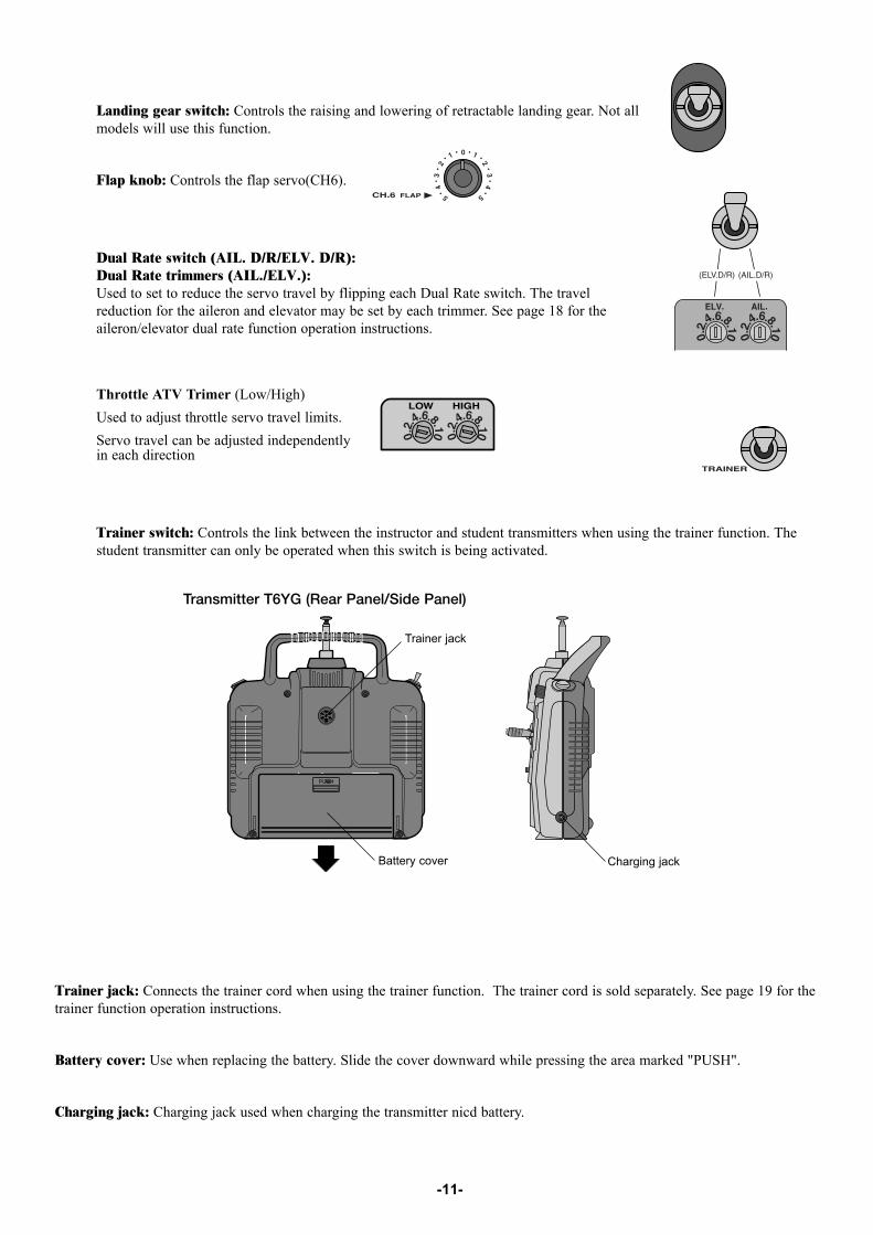
Trainer switch: Controls the link between the instructor and student transmitters when using the trainer function. Thestudent transmitter can only be operated when this switch is being activated.
Trainer jack: Connects the trainer cord when using the trainer function. The trainer cord is sold separately. See page 19 for thetrainer function operation instructions.
Battery cover: Use when replacing the battery. Slide the cover downward while pressing the area marked "PUSH".
Charging jack: Charging jack used when charging the transmitter nicd battery.
-11-
Transmitter T6YG (Rear Panel/Side Panel)
Trainer jack
Battery cover Charging jack
-12-
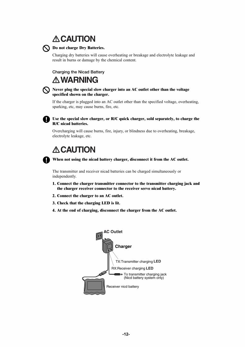
The transmitter and receiver nicad batteries can be charged simultaneously orindependently.
1. Connect the charger transmitter connector to the transmitter charging jack andthe charger receiver connector to the receiver servo nicad battery.
2. Connect the charger to an AC outlet.
3. Check that the charging LED is lit.
4. At the end of charging, disconnect the charger from the AC outlet.
When not using the nicad battery charger, disconnect it from the AC outlet.
Charging the Nicad Battery
Never plug the special slow charger into an AC outlet other than the voltagespecified shown on the charger.
If the charger is plugged into an AC outlet other than the specified voltage, overheating,sparking, etc, may cause burns, fire, etc.
Use the special slow charger, or R/C quick charger, sold separately, to charge theR/C nicad batteries.
Overcharging will cause burns, fire, injury, or blindness due to overheating, breakage,electrolyte leakage, etc.
Do not charge Dry Batteries.
Charging dry batteries will cause overheating or breakage and electrolyte leakage andresult in burns or damage by the chemical content.
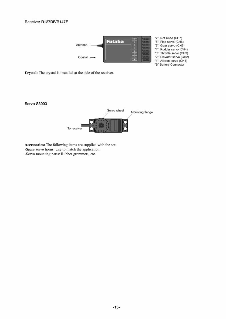
Receiver R127DF/R147F
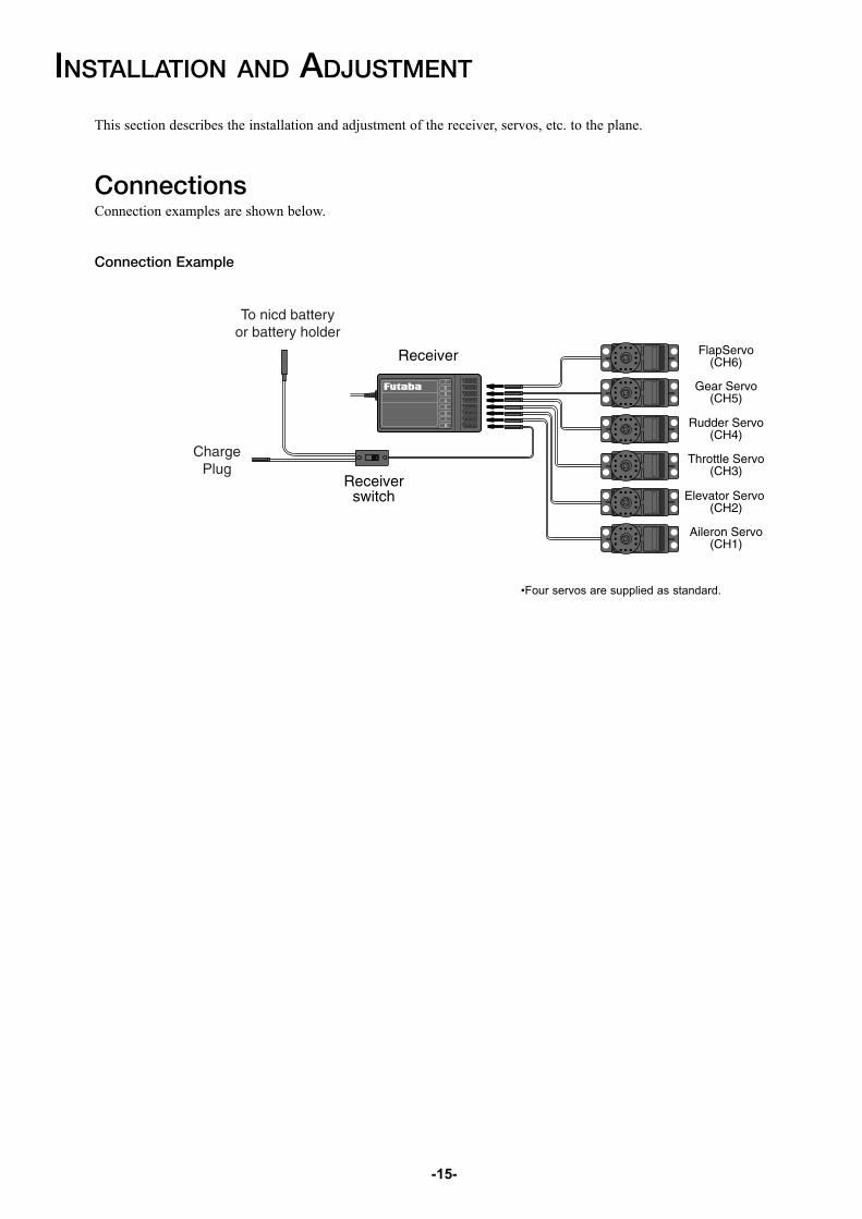
"7": Not Used (CH7) "6": Flap servo (CH6)"5": Gear servo (CH5) "4": Rudder servo (CH4)"3": Throttle servo (CH3)"2": Elevator servo (CH2)"1": Aileron servo (CH1)"B" Battery Connector
Crystal: The crystal is installed at the side of the receiver.
Servo S3003
Accessories: The following items are supplied with the set: -Spare servo horns: Use to match the application. -Servo mounting parts: Rubber grommets, etc.
-13-
Antenna
Mounting flange Servo wheel
Crystal
To receiver
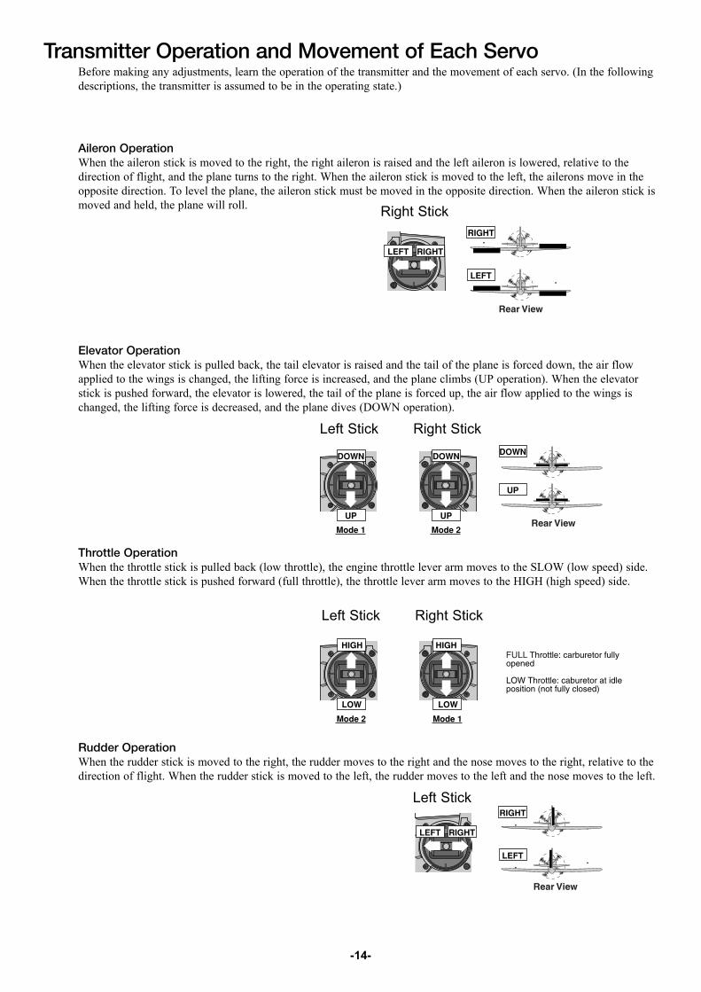
Transmitter Operation and Movement of Each ServoBefore making any adjustments, learn the operation of the transmitter and the movement of each servo. (In the followingdescriptions, the transmitter is assumed to be in the operating state.)
Aileron OperationWhen the aileron stick is moved to the right, the right aileron is raised and the left aileron is lowered, relative to thedirection of flight, and the plane turns to the right. When the aileron stick is moved to the left, the ailerons move in theopposite direction. To level the plane, the aileron stick must be moved in the opposite direction. When the aileron stick ismoved and held, the plane will roll.
Elevator OperationWhen the elevator stick is pulled back, the tail elevator is raised and the tail of the plane is forced down, the air flowapplied to the wings is changed, the lifting force is increased, and the plane climbs (UP operation). When the elevatorstick is pushed forward, the elevator is lowered, the tail of the plane is forced up, the air flow applied to the wings ischanged, the lifting force is decreased, and the plane dives (DOWN operation).
Throttle OperationWhen the throttle stick is pulled back (low throttle), the engine throttle lever arm moves to the SLOW (low speed) side.When the throttle stick is pushed forward (full throttle), the throttle lever arm moves to the HIGH (high speed) side.
Rudder OperationWhen the rudder stick is moved to the right, the rudder moves to the right and the nose moves to the right, relative to thedirection of flight. When the rudder stick is moved to the left, the rudder moves to the left and the nose moves to the left.
-14-
Right Stick
Left Stick Right Stick
Left Stick
Left Stick
Right Stick
INSTALLATION AND ADJUSTMENT
This section describes the installation and adjustment of the receiver, servos, etc. to the plane.
ConnectionsConnection examples are shown below.
Connection Example
•Four servos are supplied as standard.
-15-
-16-
(Connector Connection)Insert the receiver, servo, and battery connectors fully and firmly.
If vibration, etc. causes a connector to work loose during flight, the plane may crash.
(Receiver Vibration proofing / Waterproofing)Vibration proof the receiver and battery by wrapping them in sponge rubber orsome such material. If the receiver may get wet, waterproof them separately byplacing them in plastic bags or balloons.
If the receiver is subjected to strong vibration and shock, or gets wet, it may operateerroneously and cause a crash.
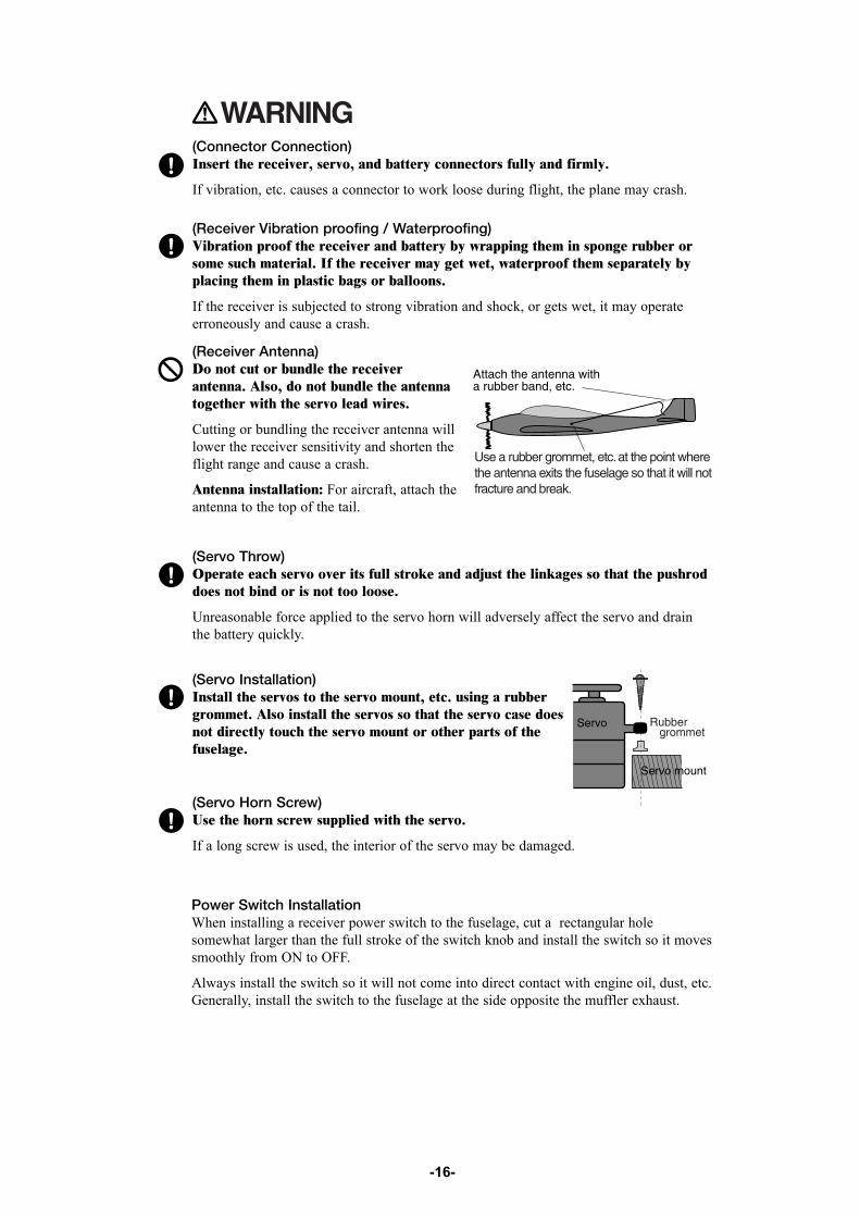
(Receiver Antenna)Do not cut or bundle the receiverantenna. Also, do not bundle the antennatogether with the servo lead wires.
Cutting or bundling the receiver antenna willlower the receiver sensitivity and shorten theflight range and cause a crash.
Antenna installation: For aircraft, attach theantenna to the top of the tail.
(Servo Throw)Operate each servo over its full stroke and adjust the linkages so that the pushroddoes not bind or is not too loose.
Unreasonable force applied to the servo horn will adversely affect the servo and drainthe battery quickly.
Power Switch InstallationWhen installing a receiver power switch to the fuselage, cut a rectangular holesomewhat larger than the full stroke of the switch knob and install the switch so it movessmoothly from ON to OFF.
Always install the switch so it will not come into direct contact with engine oil, dust, etc.Generally, install the switch to the fuselage at the side opposite the muffler exhaust.
(Servo Installation)Install the servos to the servo mount, etc. using a rubbergrommet. Also install the servos so that the servo case doesnot directly touch the servo mount or other parts of thefuselage.
(Servo Horn Screw)Use the horn screw supplied with the servo.
If a long screw is used, the interior of the servo may be damaged.

-17-
Adjustments
The operating direction, neutral position, and steering angle of each servo are adjustable.
The basic linkage and adjustments, control layout, and servo, Rx and Nicadinstallation should conform to the fuselage design drawings and kit instructionmanual. Be sure that the center of gravity is at the prescribed position.
Adjustment ProcedureBefore making any adjustments, set all the SERVO REVERSING switches on the frontof the transmitter to the lower(NOR) position and set both Dual Ratetrimmers(AIL./ELV.) to the maximum ("10") point. (Set the switches and the trimmerswith a small screwdriver, etc.)
Turn on the transmitter and receiver power switches and make the followingadjustments:
1. Check the direction of operation of each servo.
If a servo operates in the wrong direction, switch its SERVOREVERSING switch. (The direction of operation can be changed
without changing the linkage.) Pay special attention to the direction of the aileron. (Seepage 14 for a transmitter operation instruction.)
2. Check the aileron, elevator, and rudderneutral adjustment and left-right (up-down)throw.
Check that when the Tx trim levers are in thecenter, the linkage connection point isperpendicular to the servo. In this position thecontrol surfaces (aileron, elevator, rudder, etc.)must be neutral. If the neutral position of thecontrol surface has changed, reset it by
adjusting the length of the rod with the clevis.
When the throw is unsuitable (different from the deflection angle specified by the kitinstruction manual), adjust it by either changing the servo horn, the position of thelinkage on the servo horn or the linkage position on the control surface horn.
3. Check the engine throttle (speed adjustment) linkage.
Change the servo horn installation position and hole position so that the throttle isopened fully when the throttle stick is set to HIGH (forward) and is closed fully whenthe throttle stick and throttle trim are set for maximum slow (backward position andlower position, respectively).
4. After all the linkages have been connected, recheck the operating direction,throw, etc.
Before flight, adjust the aircraft in accordance with the kit and engine instructionmanuals.
5. Fly the plane and trim each control for straight and level flight.
-18-
USING OTHER FUNCTIONS
Non-slip Adjustable Lever HeadThe length of the stick head can be adjusted.
1. Unlock two heads A and B by turning them in thearrow directions.
2. Adjust the stick to the most comfortable length andlock the heads by turning them in the opposite directionof the arrows.
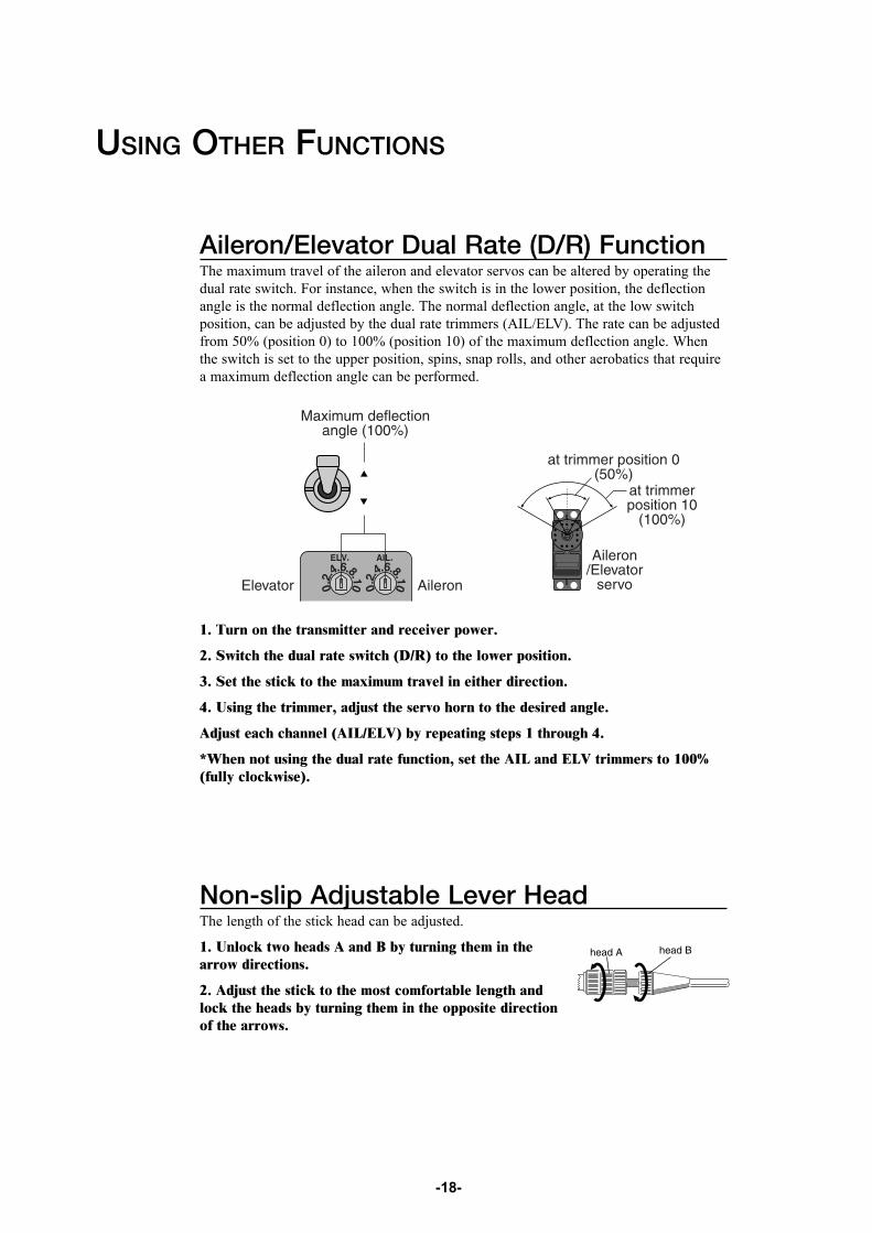
Aileron/Elevator Dual Rate (D/R) FunctionThe maximum travel of the aileron and elevator servos can be altered by operating thedual rate switch. For instance, when the switch is in the lower position, the deflectionangle is the normal deflection angle. The normal deflection angle, at the low switchposition, can be adjusted by the dual rate trimmers (AIL/ELV). The rate can be adjustedfrom 50% (position 0) to 100% (position 10) of the maximum deflection angle. Whenthe switch is set to the upper position, spins, snap rolls, and other aerobatics that requirea maximum deflection angle can be performed.
1. Turn on the transmitter and receiver power.
2. Switch the dual rate switch (D/R) to the lower position.
3. Set the stick to the maximum travel in either direction.
4. Using the trimmer, adjust the servo horn to the desired angle.
Adjust each channel (AIL/ELV) by repeating steps 1 through 4.
*When not using the dual rate function, set the AIL and ELV trimmers to 100%(fully clockwise).
-19-
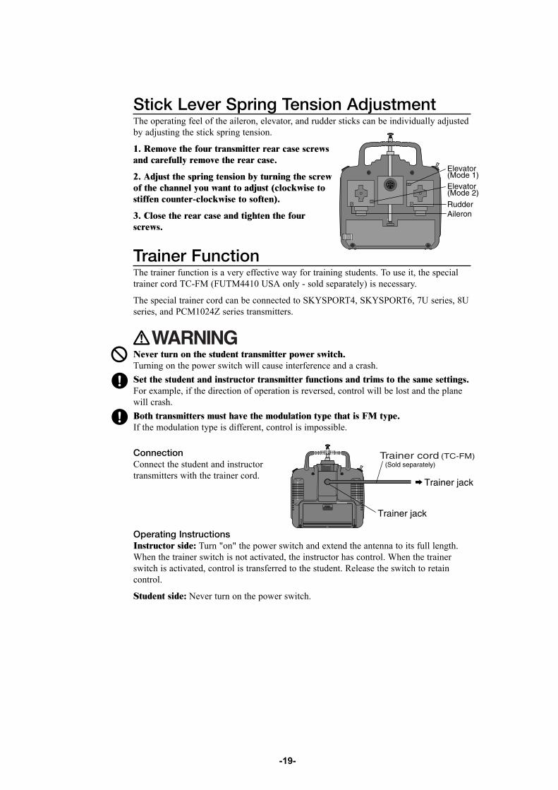
Trainer Function The trainer function is a very effective way for training students. To use it, the specialtrainer cord TC-FM (FUTM4410 USA only - sold separately) is necessary.
The special trainer cord can be connected to SKYSPORT4, SKYSPORT6, 7U series, 8Useries, and PCM1024Z series transmitters.
ConnectionConnect the student and instructortransmitters with the trainer cord.
Never turn on the student transmitter power switch. Turning on the power switch will cause interference and a crash. Set the student and instructor transmitter functions and trims to the same settings.For example, if the direction of operation is reversed, control will be lost and the planewill crash. Both transmitters must have the modulation type that is FM type. If the modulation type is different, control is impossible.
Stick Lever Spring Tension Adjustment The operating feel of the aileron, elevator, and rudder sticks can be individually adjustedby adjusting the stick spring tension.
1. Remove the four transmitter rear case screwsand carefully remove the rear case.
2. Adjust the spring tension by turning the screwof the channel you want to adjust (clockwise tostiffen counter-clockwise to soften).
3. Close the rear case and tighten the fourscrews.
Operating InstructionsInstructor side: Turn "on" the power switch and extend the antenna to its full length.When the trainer switch is not activated, the instructor has control. When the trainerswitch is activated, control is transferred to the student. Release the switch to retaincontrol.
Student side: Never turn on the power switch.

-20-
REFERENCE
Ratings
Note: Specifications and ratings are subject to change without priornotice and may differ from country to country.
Transmitter T6YG (2 sticks, 6 channels, FM transmitter)Transmitting frequency: 29, 35, 36, 40, 41, 50,60, 72, or 75 MHzModulation method: FM(Frequency Modulation)Power requirement: 12V (penlight battery x8) or9.6V nicad batteryCurrent drain: 180mA
Receiver R127DF(7 channels, FM receiver)Receiving frequency: 50, 72, or 75 MHzIntermediate frequency: 1st IF 10.7MHz 2nd IF 455kHzPower requirement: 6V (penlight battery x4), 4.8V or 6v NiCdbattery (common with servo)Current drain: 10mASize: 64.3 x 35.8 x 21mmWeight: 40.5g
Servo S3003 (Standard servo) Power requirement: 4.8V or 6V (common withreceiver)Current drain: 8mA (idle)Output torque: 3.2kg-cm at 4.8VOperating speed: 0.23sec/60 degrees at 4.8VSize: 40.4x19.8x36mmWeight: 37.2g
Receiver R147F(7 channels, FM receiver)Receiving frequency: 29, 35, 36, 40, 41, 72 MHzIntermediate frequency: 455kHzPower requirement: 6V (penlight battery x4), 4.8V or 6v NiCdbattery (common with servo)Current drain: 14mASize: 24.2 x 64 x 17.6mmWeight: 26g
-21-
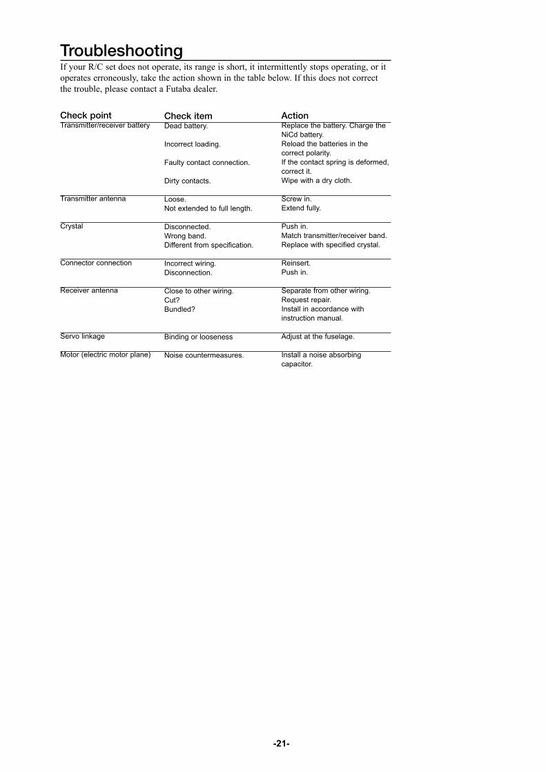
Action Replace the battery. Charge theNiCd battery. Reload the batteries in thecorrect polarity. If the contact spring is deformed,correct it. Wipe with a dry cloth.
Screw in. Extend fully.
Push in. Match transmitter/receiver band. Replace with specified crystal.
Reinsert. Push in.
Separate from other wiring. Request repair. Install in accordance withinstruction manual.
Adjust at the fuselage.
Install a noise absorbingcapacitor.
TroubleshootingIf your R/C set does not operate, its range is short, it intermittently stops operating, or itoperates erroneously, take the action shown in the table below. If this does not correctthe trouble, please contact a Futaba dealer.
Check item Dead battery.
Incorrect loading.
Faulty contact connection.
Dirty contacts.
Loose. Not extended to full length.
Disconnected. Wrong band. Different from specification.
Incorrect wiring. Disconnection.
Close to other wiring. Cut? Bundled?
Binding or looseness
Noise countermeasures.
Check point Transmitter/receiver battery
Transmitter antenna
Crystal
Connector connection
Receiver antenna
Servo linkage
Motor (electric motor plane)

-22-
REFERENCE
GlossaryThe following defines the symbols and terms used in this instruction manual.
Aileron (AIL)
Control surface on the left and right sides of themain wing of an aircraft. It usually controlsbanking of the aircraft.
Channel Represents the number of control functions. Itcan also represent the number of servos thatare operated.
Down Means "down" elevator. It is the direction inwhich the trailing edge of the elevator moves.
Dual Rate (D/R) Reduces the servo travel by flipping a switch.
Elevator (ELV) Control surface that moves up and down on thehorizontal stabilizer of an aircraft. It usuallycontrols up and down. (Altitude)
Linkage Mechanism that connects the servos and thefuselage or wing control surfaces.
Modulation Method Two modulation methods are used with radiocontrol: AM (Amplitude Modulation) and FM(Frequency Modulation). Radio sets for aircraftmainly use FM. Another method that encodesand transmits the modulated signals is called"PCM".
Neutral Means the neutral position. It is the state inwhich a transmitter stick returns to the centerwhen not operated.
Normal (NOR) For the servo reversing function, it is the normalside. The opposite side is the reverse side.
Rudder (RUD) Tail control surface that controls the direction ofthe aircraft.
Reverse (REV) With the servo reversing function, this refers tothe reverse side. The opposite side of reverse isthe normal side.
Rod A wire that connects the servos and the controlsurfaces.
Servo horn A part that is installed to the shaft of a servowhich changes the rotating motion of the servoto linear motion and transmits the linear motionto a rod. Servo horns come in various shapes.
Servo mount Base for installing a servo in the aircraft.
Stick Control for operating the transmitter.
Throttle (TH) Part that controls the air mixture at the engineintake. When opened (throttle high position), alarge air mixture is sucked in and the enginespeed increases. When closed (throttle lowposition), the engine speed decreases.
Trim A device that fine adjusts the neutral point ofeach servo for safe flying. It is a mechanismthat corrects unbalanced tendencies of theaircraft.
Up Means "up" elevator. It is the direction in whichthe trailing edge of the elevator moves.

-23-
Repair Service (for USA)
Before requesting repair, read this instruction manual again and recheck your system.Should the problem continue, request repair service as follows:
Describe the problem in as much detail as possible and send it with a detailed packinglist together with the parts that require service.• Symptom (Including when the problem occurred) • System(Transmitter, Receiver, Servos and model numbers)• Model (Model name) • Model Numbers and Quantity• Your Name, Address, and Telephone Number.
R
1610 Interstate Dr. Champaign, IL 61822 (217) 398-0007
FUTABA CORPORATIONMakuhari Techno Garden Bldg., B6F 1-3 Nakase, Mihama-ku, Chiba 261-8555, JapanPhone: (043) 296-5118 Facsimile: (043) 296-5124


![INSTRUCTION MANUAL - Hobbico, Inc. - largest U.S ...manuals.hobbico.com/flz/flza2102-manual.pdfFLZA2102 SPECIFICATIONS Wingspan: 15.9 in [404mm] Total Length: 15.7 in [399mm] Weight:](https://img.pdfslide.net/doc/110x75/5aa505477f8b9ae7438cd38c/instruction-manual-hobbico-inc-largest-us-specifications-wingspan-159.jpg)