Embed Size (px)
Citation preview
PAGE 1IOM R-SERIES SLIP RINGP/N 969000 - Rev. 2.1 - 2004.03.03
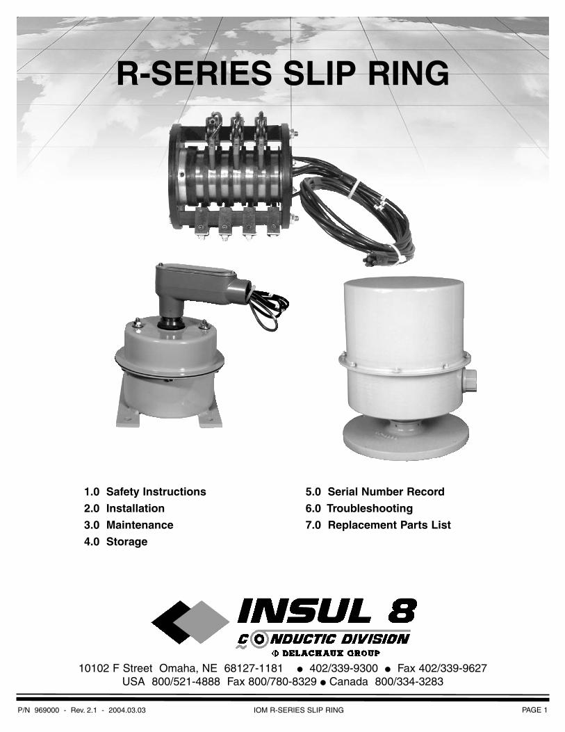
R-SERIES SLIP RING
10102 F Street Omaha, NE 68127-1181 ● 402/339-9300 ● Fax 402/339-9627USA 800/521-4888 Fax 800/780-8329 ● Canada 800/334-3283
1.0 Safety Instructions
2.0 Installation
3.0 Maintenance
4.0 Storage
5.0 Serial Number Record
6.0 Troubleshooting
7.0 Replacement Parts List
Disclaimer/General Warranty
INSUL-8 CORPORATION
The technical data and images which appear in this manual are for informational purposes only. NO WARRANTIES,EXPRESSED OR IMPLIED, INCLUDING WARRANTIES OF MERCHANTABILITY OR FITNESS FOR A PARTICULARPURPOSE, ARE CREATED BY THE DESCRIPTIONS AND DEPICTIONS OF THE PRODUCTS SHOWN IN IN THISMANUAL. Insul-8 makes no warranty (and assumes no liability) as to function of equipment or operation of systems builtaccording to customer design or of the ability of any of its products to interface, operate or function with any portions ofcustomer systems not provided by Insul-8.
Seller agrees to repair or exchange the goods sold hereunder necessitated by reason of defective workmanship andmaterial discovered and reported to Seller within one year after shipment of such goods to Buyer.
Except where the nature of the defect is such that it is appropriate, in Seller’s judgement, to effect repairs on site. Seller’s obligation hereunder to remedy defects shall be limited to repairing or replacing (at Seller’s option) FOB point of originalshipment by Seller, any part returned to Seller at the risk and cost of Buyer. Defective parts replaced by Seller shallbecome the property of Seller.
Seller shall only be obligated to make such repair or replacement of the goods which have been used by Buyer only inservice recommended by Seller and altered only as authorized by Seller. Seller is not responsible for defects which arisefrom improper installation, neglect, or improper use or from normal wear and tear.
Additionally, Seller’s obligation shall be limited by the manufacturer’s warranty, (and shall be not further warranted by Seller)for all parts procured from others according to published data, specifications or performance information not designed byor for Seller.
Seller further agrees to replace or at Seller’s option to provide a refund of the sales price of any goods that did not conform to applicable specifications or which differ from that agreed to be supplied which non-conformity is discovered andforthwith reported to Seller within thirty (30) days after shipment to Buyer. Seller’s obligation to replace or refund the purchase price for non-conforming goods shall arise once Buyer returns such good FOB point of original shipment by Sellerat the risk and cost of Buyer, Goods replaced by Seller shall be come property of Seller.
There is no guarantee or warranty as to anything made or sold by Seller, or any service performed, except as to title andfreedom from encumbrances and, except as herein expressly stated and particularly, and without limiting the foregoing,there is no guarantee or warranty, express or implied, of merchantability or of fitness for any particular purpose or againstclaim of infringement or the like.
Seller makes no warranty (and assumes no liability) as to function of equipment or operation of systems built to Buyer’sdesign or of the ability of any goods to interface, operate or function with any portions of Buyer’s system not provided bySeller.
Seller’s liability on any claim, whether in contract, or (including negligence), or otherwise, for any loss or damage arisingout of, connected with, or resulting from the manufacture, sale, delivery, resale, repair, replacement or use of any productsor services shall in no case exceed the price paid for the product or services or any part thereof which give rise to the claim.In no event shall Seller be liable for consequential, special, incidental or other damages, nor shall Seller be liable in respectto personal injury or damage to property on the subject matter hereof unless attributable to gross misconduct of Seller,which shall mean an act of omission by Seller demonstrating reckless disregard of the foreseeable consequences thereof.
Seller is not responsible for incorrect choice of models or where products are used in excess of their rated and recommended capacities and design functions or under abnormal conditions. Seller assumes no liability for loss of time,damage or injuries to property or persons resulting from the use of Seller’s products. Buyer shall hold Seller harmless fromall liability, claims, suits and expenses in connection with loss or damage resulting from operation of products, utilizationof services, respectively, of Seller and shall defend any suit or action which might arise there from in Buyer’s name - provided that Seller shall have the right to elect to defend any such suit or action for the account of Buyer. The foregoingshall be the exclusive remedies of the buyer and all persons and entitles claiming through the Buyer.
P/N 969000 - Rev. 2.1 - 2004.03.03PAGE 2 IOM R-SERIES SLIP RING
PAGE 3IOM R-SERIES SLIP RINGP/N 969000 - Rev. 2.1 - 2004.03.03
1.0.1 ATTENTION: Read this entire booklet prior to attempting ant installation and/ or maintenance.
1.1 Electrical Warnings
1.1.1 Install and ground the slip ring and the entire unit in accordance with the NationalElectric Code and local codes and/or ordinances.
1.1.2 DANGER: Hazard of electrical shock or burn. Always disconnect the power from the collector ring before attempting to perform anyservice function. Follow lock out/tag-out procedures as outlined in OSHA section1910.147 where appropriate.
1.1.3 Do not use this slip ring with electrical loads greater than the rated current and voltage.(See page 8).
1.1.4 Information regarding the current and voltage rating of each slip ring is recorded on atag permanently fastened to the ring assembly.
1.2 Operational Warnings
1.2.1 Slip rings must be enclosed and protected from any contact by personnel. Means for theprovision of this protection is the responsibility ofthe user. Various enclosure styles are availablefrom Insul-8.
1.2.2 WARNING: Modification of this equipment may cause excessive wear or failure and will voidthe warranty.
1.2.3 WARNING: Modification may cause safety and fire hazards. Contact the manufactureregarding any modifications which could affectsafety or reliability.
1.3 Maintenance Warnings
1.3.1 Exercise care while servicing, adjusting, and operating the slip ring.
1.3.2 Periodically check all fasteners and hardware to assure tightness.
1.3.3 Install all mounting fasteners and hardware so as to maintain tightness undervibration.
1.3.4 If you have any questions about the use or the installation of your R-Series Slip Ring thatare not answered in this documentation contactthe factory for assistance.
U.S. 1-800-521-4888Canada: 1-800-667-2487
1.4 Specifications & Listings
1.4.1 R-Series Slip Ring products are built to UL specifications but are not generally or certified orlisted by an independent certifying or regulatorybody.
1.4.2 The following specifications apply to all R- Series Slip Rings.
1.4.2.1 R-Series Slip Rings are intended for industrial use and require a permanent mountingmeans.
1.4.2.2 Maximum RPM for units with out ball bearings is 125. Maximum for units with ball bearings is 500 RPM.
1.5 Temperature & Ampere / Voltage Ratings
1.5.1 R-Series Slip Rings withstand a maximum ambient temperature of 220O F.
1.5.2 The actual ampacity of the Slip Ring assembly may be affected by the type and sizeof the core lead wire (refer to NEC Table 310-16,17, 18, 19 and applicable notes).
1.6 Markings
1.6.1 Every slip ring is marked with a label on the outboard bearing (or enclosure) whichincludes the Insul-8 name and logo, the productcatalog number and the individual product serialnumber.
1.6.2 The marking on slip rings include the maximum amperage and voltage.
1.0 Safety
P/N 969000 - Rev. 2.1 - 2004.03.03PAGE 4
2.1 Handling
2.1.1 Carry unit by core attachment or through core rod for vertical support.
2.1.2 Carry unit by horizontally supporting outboard bearings.
2.1.3 NOTE: NEVER SUPPORT UNIT BY CORE LEADS.
2.2 Application Types
2.2.1 Slip ring assemblies can be purchased without an enclosure. User must enclose thering appropriately to meet safety codes and toprotect the ring.
◆ wrap around shroud
◆ revolving enclosure with shaft flange
◆ stationary enclosure with rotating elbow
2.3 Mounting & Connections
2.3.1 Slip Rings w/o Enclosure or with Wrap Around Shroud (R-U)
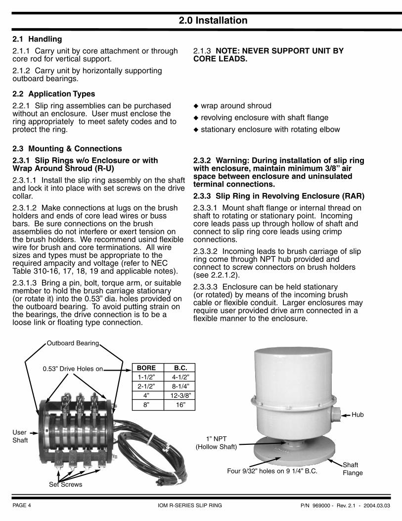
2.3.1.1 Install the slip ring assembly on the shaft and lock it into place with set screws on the drivecollar.
2.3.1.2 Make connections at lugs on the brush holders and ends of core lead wires or bussbars. Be sure connections on the brush assemblies do not interfere or exert tension onthe brush holders. We recommend usind flexiblewire for brush and core terminations. All wiresizes and types must be appropriate to therequired ampacity and voltage (refer to NECTable 310-16, 17, 18, 19 and applicable notes).
2.3.1.3 Bring a pin, bolt, torque arm, or suitable member to hold the brush carriage stationary (or rotate it) into the 0.53” dia. holes provided onthe outboard bearing. To avoid putting strain onthe bearings, the drive connection is to be aloose link or floating type connection.
2.3.2 Warning: During installation of slip ring with enclosure, maintain minimum 3/8” airspace between enclosure and uninsulatedterminal connections.
2.3.3 Slip Ring in Revolving Enclosure (RAR)
2.3.3.1 Mount shaft flange or internal thread on shaft to rotating or stationary point. Incomingcore leads pass up through hollow of shaft andconnect to slip ring core leads using crimp connections.
2.3.3.2 Incoming leads to brush carriage of slip ring come through NPT hub provided and connect to screw connectors on brush holders(see 2.2.1.2).
2.3.3.3 Enclosure can be held stationary (or rotated) by means of the incoming brushcable or flexible conduit. Larger enclosures mayrequire user provided drive arm connected in aflexible manner to the enclosure.
IOM R-SERIES SLIP RING
2.0 Installation
0.53” Drive Holes on
Outboard Bearing
BORE1-1/2”2-1/2”
4”8”
B.C.4-1/2”8-1/4”12-3/8”
16”
UserShaft
Set Screws
Hub
ShaftFlange
1” NPT(Hollow Shaft)
Four 9/32” holes on 9 1/4” B.C.
PAGE 5IOM R-SERIES SLIP RINGP/N 969000 - Rev. 2.1 - 2004.03.03
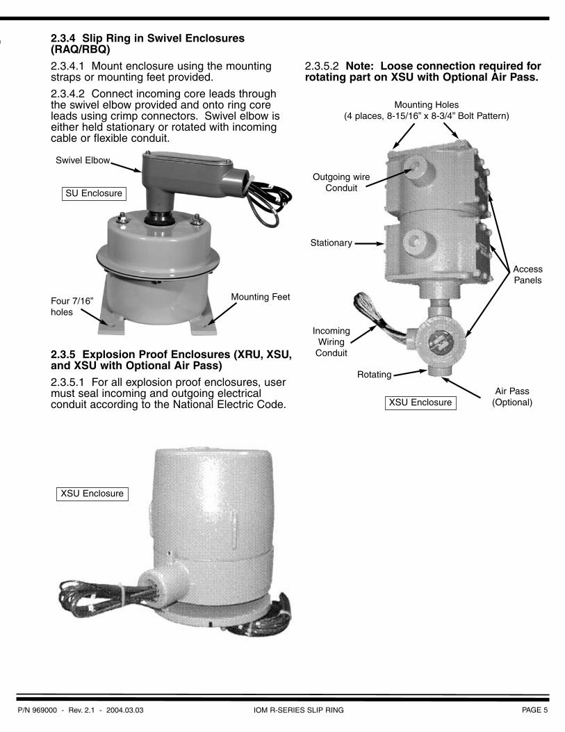
2.3.4 Slip Ring in Swivel Enclosures(RAQ/RBQ)
2.3.4.1 Mount enclosure using the mounting straps or mounting feet provided.
2.3.4.2 Connect incoming core leads through the swivel elbow provided and onto ring coreleads using crimp connectors. Swivel elbow iseither held stationary or rotated with incomingcable or flexible conduit.
2.3.5 Explosion Proof Enclosures (XRU, XSU,and XSU with Optional Air Pass)
2.3.5.1 For all explosion proof enclosures, user must seal incoming and outgoing electrical conduit according to the National Electric Code.
2.3.5.2 Note: Loose connection required for rotating part on XSU with Optional Air Pass.
Swivel Elbow
SU Enclosure
Four 7/16”holes
Mounting Feet
XSU Enclosure
Mounting Holes(4 places, 8-15/16” x 8-3/4” Bolt Pattern)
Outgoing wireConduit
Stationary
Rotating
Air Pass(Optional)
AccessPanels
IncomingWiring
Conduit
XSU Enclosure
P/N 969000 - Rev. 2.1 - 2004.03.03PAGE 6
3.1 Lubrication
3.1.1 All bearings are lubricated for life at the factory. Additional lubrication should not berequired.
3.1.2 CAUTION: Do not apply any lubricants or solvent cleaning agents to any part of theslip ring.
3.2 Inspections
3.2.1 Make the first inspection shortly after installation and before operation. Make continuing inspections on a regular basis afterevery 200-400 hours of operation under normalconditions.
3.2.2 Brush Holders
3.2.2.1 Inspect brush holders for proper alignment. Locate brush holders so that theentire brush contact surface rides squarely onthe ring with the brush moving freely in the brushholder. Position brush holders so the brushmakes contact with the middle of the conductorand is not offset.
3.2.2.2 Check brush holder clamps for tightness.Set clamp bolts at 10 in-lb. max.
3.2.2.3 Inspect brush terminations at the holder to assure that no external force is imposed onthe holder. We recommend flexible or soft wireleads for these terminations. Use externalclamps to support the entire weight of the leads.
3.2.3 Brushes
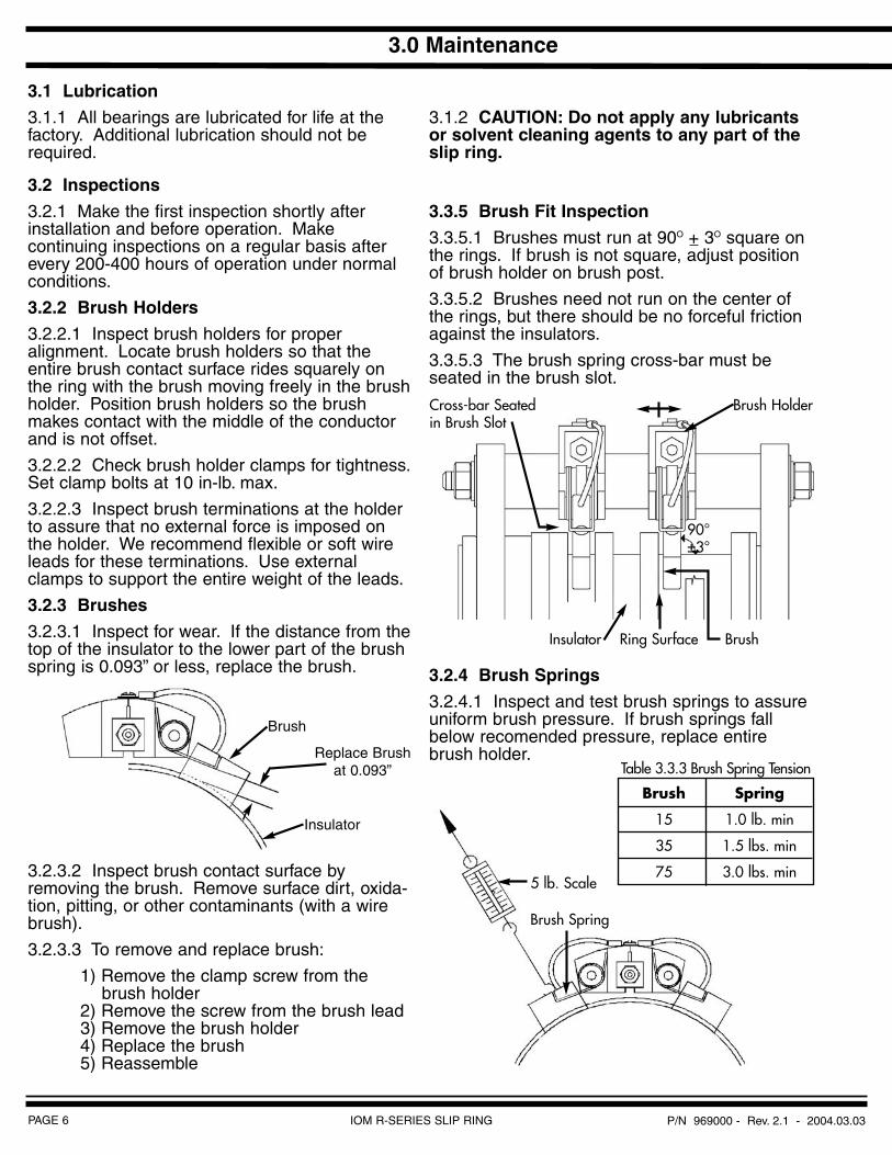
3.2.3.1 Inspect for wear. If the distance from the top of the insulator to the lower part of the brushspring is 0.093” or less, replace the brush.
3.2.3.2 Inspect brush contact surface byremoving the brush. Remove surface dirt, oxida-tion, pitting, or other contaminants (with a wirebrush).
3.2.3.3 To remove and replace brush:
1) Remove the clamp screw from the brush holder
2) Remove the screw from the brush lead3) Remove the brush holder4) Replace the brush5) Reassemble
3.3.5 Brush Fit Inspection
3.3.5.1 Brushes must run at 90O + 3O square on the rings. If brush is not square, adjust positionof brush holder on brush post.
3.3.5.2 Brushes need not run on the center of the rings, but there should be no forceful frictionagainst the insulators.
3.3.5.3 The brush spring cross-bar must be seated in the brush slot.
3.2.4 Brush Springs
3.2.4.1 Inspect and test brush springs to assure uniform brush pressure. If brush springs fallbelow recomended pressure, replace entirebrush holder.
IOM R-SERIES SLIP RING
3.0 Maintenance
Brush
Replace Brushat 0.093”
Insulator
Cross-bar Seatedin Brush Slot
Brush Holder
BrushRing SurfaceInsulator
90°±3°
5 lb. Scale
Brush Spring
Brush Spring
15 1.0 lb. min
35 1.5 lbs. min
75 3.0 lbs. min
Table 3.3.3 Brush Spring Tension
PAGE 7IOM R-SERIES SLIP RINGP/N 969000 - Rev. 2.1 - 2004.03.03
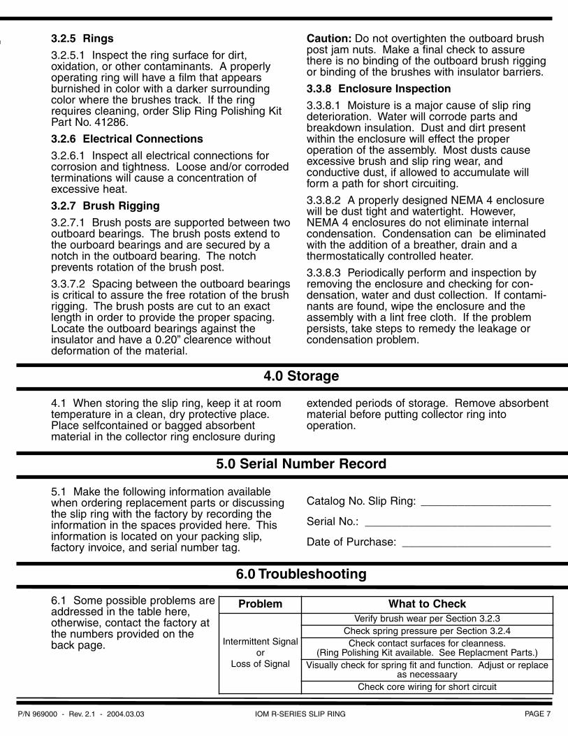
4.1 When storing the slip ring, keep it at roomtemperature in a clean, dry protective place.Place selfcontained or bagged absorbent material in the collector ring enclosure during
extended periods of storage. Remove absorbentmaterial before putting collector ring into operation.
5.1 Make the following information availablewhen ordering replacement parts or discussingthe slip ring with the factory by recording theinformation in the spaces provided here. Thisinformation is located on your packing slip, factory invoice, and serial number tag.
Catalog No. Slip Ring: _____________________
Serial No.: ______________________________
Date of Purchase: ________________________
6.1 Some possible problems areaddressed in the table here, otherwise, contact the factory atthe numbers provided on theback page.
3.2.5 Rings
3.2.5.1 Inspect the ring surface for dirt, oxidation, or other contaminants. A properlyoperating ring will have a film that appears burnished in color with a darker surroundingcolor where the brushes track. If the ringrequires cleaning, order Slip Ring Polishing KitPart No. 41286.
3.2.6 Electrical Connections
3.2.6.1 Inspect all electrical connections for corrosion and tightness. Loose and/or corrodedterminations will cause a concentration of excessive heat.
3.2.7 Brush Rigging
3.2.7.1 Brush posts are supported between two outboard bearings. The brush posts extend tothe ourboard bearings and are secured by anotch in the outboard bearing. The notch prevents rotation of the brush post.
3.3.7.2 Spacing between the outboard bearings is critical to assure the free rotation of the brushrigging. The brush posts are cut to an exactlength in order to provide the proper spacing.Locate the outboard bearings against the insulator and have a 0.20” clearence withoutdeformation of the material.
Caution: Do not overtighten the outboard brush post jam nuts. Make a final check to assurethere is no binding of the outboard brush riggingor binding of the brushes with insulator barriers.
3.3.8 Enclosure Inspection
3.3.8.1 Moisture is a major cause of slip ring deterioration. Water will corrode parts andbreakdown insulation. Dust and dirt presentwithin the enclosure will effect the proper operation of the assembly. Most dusts causeexcessive brush and slip ring wear, and conductive dust, if allowed to accumulate willform a path for short circuiting.
3.3.8.2 A properly designed NEMA 4 enclosure will be dust tight and watertight. However,NEMA 4 enclosures do not eliminate internalcondensation. Condensation can be eliminatedwith the addition of a breather, drain and a thermostatically controlled heater.
3.3.8.3 Periodically perform and inspection by removing the enclosure and checking for con-densation, water and dust collection. If contami-nants are found, wipe the enclosure and theassembly with a lint free cloth. If the problempersists, take steps to remedy the leakage orcondensation problem.
4.0 Storage
5.0 Serial Number Record
6.0 Troubleshooting
Problem What to Check
Intermittent Signalor
Loss of Signal
Verify brush wear per Section 3.2.3Check spring pressure per Section 3.2.4Check contact surfaces for cleanness.
(Ring Polishing Kit available. See Replacment Parts.)Visually check for spring fit and function. Adjust or replace
as necessaaryCheck core wiring for short circuit
P/N 969000 - Rev. 2.1 - 2004.03.03PAGE 8 IOM R-SERIES SLIP RING
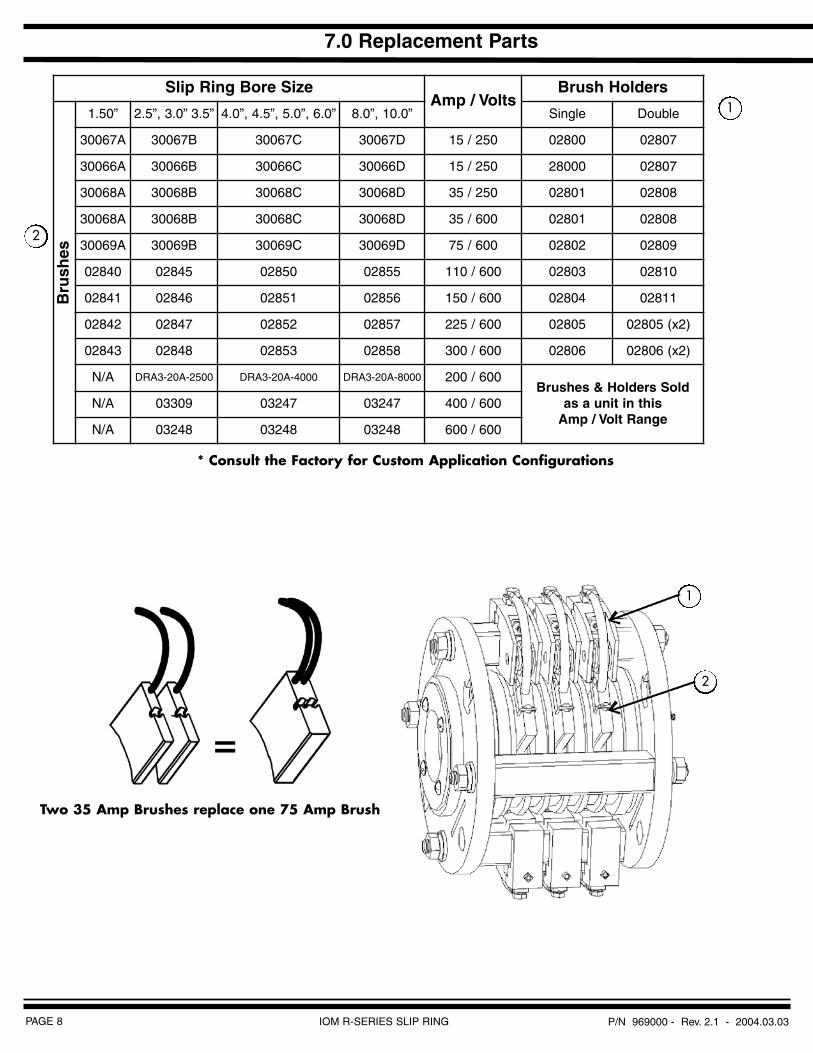
7.0 Replacement Parts
1
2
* Consult the Factory for Custom Application Configurations
Two 35 Amp Brushes replace one 75 Amp Brush
1
2
Slip Ring Bore SizeAmp / Volts
Brush Holders
Bru
shes
1.50” 2.5”, 3.0” 3.5” 4.0”, 4.5”, 5.0”, 6.0” 8.0”, 10.0” Single Double
30067A 30067B 30067C 30067D 15 / 250 02800 02807
30066A 30066B 30066C 30066D 15 / 250 28000 02807
30068A 30068B 30068C 30068D 35 / 250 02801 02808
30068A 30068B 30068C 30068D 35 / 600 02801 02808
30069A 30069B 30069C 30069D 75 / 600 02802 02809
02840 02845 02850 02855 110 / 600 02803 02810
02841 02846 02851 02856 150 / 600 02804 02811
02842 02847 02852 02857 225 / 600 02805 02805 (x2)
02843 02848 02853 02858 300 / 600 02806 02806 (x2)
N/A DRA3-20A-2500 DRA3-20A-4000 DRA3-20A-8000 200 / 600Brushes & Holders Sold
as a unit in this Amp / Volt Range
N/A 03309 03247 03247 400 / 600
N/A 03248 03248 03248 600 / 600

PAGE 9IOM R-SERIES SLIP RINGP/N 969000 - Rev. 2.1 - 2004.03.03
Notes
P/N 969000 - Rev. 2.1 - 2004.03.03PAGE 10 IOM R-SERIES SLIP RING
Notes
PAGE 11IOM R-SERIES SLIP RINGP/N 969000 - Rev. 2.1 - 2004.03.03
Notes
Moving People Moving Products
Moving Forward
Conductor Bar
Cable Festoon Systems
Radio Controls
Push-Button Pendants Station
Cable & Hose Reels
Motor Driven Reels
Slip Rings
Visit us on the web at:www.insul-8.com
CANADA
175 BOULEVARD J.F. KENNEDY
ST. JEROME, QUEBEC J7Y4B5
PHONE: 450 / 565-9900TOLL FREE: 800 / 667-2487
FAX: 512 / 432-6985
E-MAIL: [email protected]
USA
10102 F STREET
OMAHA, NE 68127
PHONE: 402 / 339-9300TOLL FREE: 800 / 521-4888
FAX: 402 / 339-9627
E-MAIL: [email protected]
AUSTRALIA
14 ENGLAND STREET
DANDENONG, VICTORIA 3175
PHONE: 3 / 9706 88 44FAX: 3 / 794 92 98
E-MAIL: [email protected]
IOM R-SERIES SLIP RINGPAGE 12 P/N 969000 - Rev. 2.1 - 2004.03.03