Embed Size (px)
Citation preview

I SHOP A U L

Copyright © 2012, Forel Publishing Company, LLC, Woodbridge, Virginia
All Rights Reserved. No part of this book may be used or reproduced in any manner whatsoever without written permission of Forel Publishing Company, LLC. For information write to Forel
Publishing Company, LLC, 3999 Peregrine Ridge Ct., Woodbridge, VA 22192
1952, 1953 and 1954 Ford Passenger Car Shop Manual EAN: 978-1-60371-061-9
ISBN: 1-60371-061-2
Forel Publishing Company, LLC 3999 Peregrine Ridge Ct. Woodbridge, VA 22192
Email address: [email protected] Website: http://www.ForelPublishing.com
This publication contains material that is reproduced and distributed under a license from Ford Motor Company. No further reproduction or distribution of the Ford Motor Company material is
allowed without the express written permission of Ford Motor Company.
Note from the Publisher This product was created from the original Ford Motor Company’s publication. Every effort has been made to use the original scanned images, however, due to the condition of the material; some pages have been modified to remove imperfections.
Disclaimer
Although every effort was made to ensure the accuracy of this book, no representations or warranties of any kind are made concerning the accuracy, completeness or suitability of the information, either expressed or implied. As a result, the information contained within this book should be used as general information only. The author and Forel Publishing Company, LLC shall have neither liability nor responsibility to any person or entity with respect to any loss or damage caused, or alleged to be caused, directly or indirectly by the information contained in this book. Further, the publisher and author are not engaged in rendering legal or other professional services. If legal, mechanical, electrical, or other expert assistance is required, the services of a competent professional should be sought.


PREFACE This manual combines under one cover com
plete service information for the 1952 Ford Passenger Car. All aspects of the servicing of the parts, assemblies, or systems involved will be found here. Repair men will find step by step procedures plus disassembled views of all of the assemblies. The diagnostician will find that working procedures for each kind of trouble he will encounter are covered. Maintenance and lubrication data is provided for those interested in this aspect of service. Service Managers and salesmen will find hints of everyday care that they can pass on to their customers. Collision men will find construction detail well illustrated to assist them in collision work. Electrical men will find simply written principles, not only of operation, but of testing as well for each of the electrical units or systems. Upholstery men will find how-to-do-it procedures for their work.
Step-by-step procedures for the disassembly, inspection, and repair are presented throughout this manual. In addition, each assembly has been illustrated disassembled, with each of the component parts arranged in the order of assembly or disassembly. In many cases, a glance at these illustrations will tell you all you need to know about how the parts go together. These illustrations carry basic part numbers for each of the parts. These basic numbers plus the model number of the car will permit you to order parts from any Ford dealer even though you may not have a "Parts Book."
In recognition of the specialization that is currently practiced in many service establishments, this manual has been divided into five major divisions. These five parts are as follows:
Part ONE-POWER PLANT -has to do with the Ford engines and the various systems that are necessary to their operation. These include fuel. system, ignition system, and the cooling system.
Part TWO-CHASSIS-starting with the clutch, covers the entire power train (clutch, standard transmission, Overdrive, Fordomatic transmission, drive line, rear axles, etc.) and the running gear (wheels, tires, brakes, springs, suspension, frames, steering gear, and linkages, etc.).
Part THREE - ELECTRICAL AND ACCESSORIES-covers all of the electrical systems and units (other than ignition which is covered in Part ONE) and all of the accessories, except the Overdrive and Fordomatic trans-
missions which are covered in Part TWO, for Ford cars.
Part FOUR-BODIES-contains complete information on the maintenance and repair of all body components, including adjustment and alignment not only of the body proper, but also of doors, deck lids, hoods, and fenders. In addition, convertible top maintenance and glass adjustments are given.
Part FIVE-MAINTENANCE, TROUBLE SHOOTING, AND SPECIFICATIONS-has been arranged in the back of the book separately for the convenience of quick service men. In this part, all of the information ordinarily required for quick service men and service salesmen has been combined into three separate chapters.
The Table of Contents on the next page shows not only the part break-down as described above, but also the chapters that have been established in each of the five parts. Each chapter has been divided into sections which also are listed in the Table of Contents. Regardless of the ,aspect of service in which you are interested or the unit of the vehicle in .which you may be specializing, a glance at the Table of Contents will quickly direct you to the portion of this manual in which you are interested. If you are interested in maintenance procedures, trouble shooting, or specifications, the information you desire will be found in Part FIVE. Otherwise, it will fall in one of the four other parts. A quick glance at the chapter and section listings under the part involved' will direct you to the page desired.
Throughout this manual the top of each lefthand, even-numbered page gives the name of the chapter; and the top of each right-hand, oddnumbered page gives the name of the section involved. Thus, regardless of where you open the manual, a glance at the top of the two pages will tell you exactly what subject matter is discussed at that point.
No one expects even the most experienced mechanic to remember all details of servicing these cars and you will find that you will have to occasionally refer to this manual. Keep your manual where it will be readily available for reference at all times.
FORD DIVISION FORD MOTOR COMPANY SERVICE DEPARTMENT

TABLE OF CONTENTS Preface ........ • . . .. .• . . . . . . . . . . . . . . . . . . . . . . . . . . . . . . . . . . . . . . . . . . . . . . . . . . . . . . . . . . . . . . . . . . Page
2
Part ONE-POWER PLANT
CHAPTER I-EAA SERIES-6·CYLINDER ENGINE
Page
Section 1 Engine Removal and Installation. . . . . . 5 2 Manifolds. . . . . . . . . . . . . . . . . . . . . . . . 8 3 Cylinder Head . . . . . . . . . . . . . . . . . 9
Page Section 6 Crankshaft Damper . . . . . . . . . . . . . . . . . . 17
7 Cylinder Front Cover and Oil Seal . . . . . 17 . 8 Camshaft Sprocket, Camshaft, and
4 Valves, Valve Mechanism, and ås .. ... .. . .... . .. ........ . 18 Valve Lash Adjustment. . . . . . 11
5 Oil Pan, Filtc:r. Oil Pump and Pressure Relief Valve .. . . . . . . . . 14
9 Flywheel, Crankshaft. and Bearings .... 20 10 Connecting Rods, Pistons, and Rings ... 26 11 Exhaust System . . . . . . . . . . . . . . . . . . . .. 31
CHAPTER II-EAB SERIES-8·CYLINDER ENGINE
Section 1 Engine Removal and Installation .. .. . . 34 Section 7 Valves, Springs, Guides, and Seats ..... 41 2 Manifolds .... ... ............... 36 8 Camshaft Gear, Camshaft, and 3 Cylinder Heads ......... . ..... . 37 Bearings ....... . 43 4 Oil Pan, Oil Pump, and Pressure
.. . . .... .. .. . 9 Flywheel, Crankshaft, and Bearings .... 45 Relief Valve ........ . .. .......... 38
5 Crankshaft Pulley Replacement . ...... 40 10 Connecting Rods, Pistons, and Rings ... 50 6 Cylinder Front Cover .... . . . .. .. ..... 41 II Exhaust System ......... . 54
CHAPTER III-IGNITION, FUEL, AND COOLING
Section 1 Ignition ....... . ... ................. 57 Section 6 g-Cylinder Carburetor Overhaul . ...... 75 2 Distributor Minor Repair and 7 Fuel Pumps and Vacuum Booster ...... 78
Adjustment .................... . . . 60 8 Fuel Tanks and Lines . . .... ... . .. .... 82 3 Distributor Overhaul . .. . ...... ... 63 9 Fans and Belts ................... . . . 82 4 Carburetor Operation and Adjustment .. 67 10 Water Pumps ....................... 84 5 6-Cylinder Carburetor Overhaul .. . .. 71 II Radiator, Hoses, and Thermostats ..... 86
Part TWO-CHASSIS
CHAPTER I-CLUTCH AND TRANSMISSION
Section 1 Clutch .. ... ............ . .. . 2 Transmission Replacement ..
89 92
Section 3 Transmission Overhaul . . . . . . . • . . • . . .. 92 4 Gear Shift Linkage . . . . . . . . . . . . . . . . . .. 97
CHAPTER II-OVERDRIVE
Section 1 Operating Principles . . . . . . . . . . . . . . . 99 Section 4 Assembly .. . 2 Removal... . . . . . . . . . 102 5 Installation. 3 Disassembly and Inspection . .. ...... . . 103
CHAPTER III-FORDOMATIC TRANSMISSION
Section 1 Construction and Operation. .. . 107 Section 4 Transmission Overhaul ...... . . 2 Maintenance and Adjustment . . . . . . . .. 117 5 Converter Overhaul. . . . .... ... ... . 3 Replacement .. . .. ... . ............... 122
CHAPTER IV-REAR AXLE AND DRIVE LINES
105 106
128 149
Section 1 Passenger Car R ear Axle ..... 151
159
Section 3 Drive Lines. . . . . . . . . . . . . . . . . . . . . . . .. 163 2 Station Wagon and Sedan Delivery
Rear Axle . . .. . ............ . .. .
CHAPTER V-RUNNING GEAR
Section 1 Frames .... ........ .. . 165 Section 5 Steering Gear ...... . .... . .. ... . ..... 174 2 Front Suspension .. . 168 6 Steering Linkage .. . . ... .. .. . . . .. ... .. 178 3 Rear Springs . . ...... . ..... ...... 172 7 Wheels and Tires ...... . . . . ..... ... .. 182 4 Shock Absorbers .. .. . . 173 8 Hubs and Bearings .. . .. .... ..... ... .. 184

CHAPTER VI-BRAKES Page
Section 1 Adjustments........................ 188 2 Hydraulic System .................... 189 3 Brake Assemblies. . . . . . . . . . . . . . . . . . .. 193
Page
Section 4 Brake Drums. . . . . . . . . . . . . . . . . . . . . .. 194 5 Parking Brake ....................... 194
Part THREE-ELECTRICAL AND ACCESSORIES CHAPTER I-ELECTRICAL SYSTEMS
Section 1 Generating System and Battery ....... 197 2 Starting System. . . . . . . . . . . . . . . . . . . .. 213 3 Lighting System ................... ,'. 219
Section 4 Horns.............................. 22 6 5 Instruments. ~. . . . . . . . . . . . . . . . . . . . . .. 22 7
CHAPTER II-ACCESSORIES
Section 1 Radio.............................. 231 2 Heater............................. 237
Section 3 Windshield Wiper .................... 240 4 Miscellaneous Accessories. . . . . . . . . . . .. 241
Part FOUR-BODIES CHAPTER I-BODY CONSTRUCTION AND MAINTENANCE
Section 1 Construction Details and Sealer Section 5 Front Fender Alignment .............. 257 Application ....................... 245 6 Body Alignment ..................... 259
2 Door Alignment ..................... 251 7 Quarter Panel Repair. . . . . ........... 261 3 Deck Lid Alignment ................. 254
4 Hood Alignment ..................... 256 8 General Body Maintenance ........... 263
CHAPTER II-HARDWARE, GLASS, UPHOLSTERY, AND FLAT TRIM Section 1
2 3 4 5
Door Locking Mechanism. . . . . . . . . . . .. 265 6 Grille and Hood. . . . . . . . . . . . . . . . . . . .. 279 Window Regulators .................. 268 7 Deck Lid Locking Mechanism ....... " 280 Door Ventilator Assembly... . . . . . . . . .. 270 Door and Quarter Glass. . . . . . . . . . . . .. 271 Windshield and Rear Window. . . . . . . .. 274
8 Door and Quarter Trim Panels. . . . . . .. 281 9 Headlining Replacement. . . . . . . . . . . . .. 284
CHAPTER III-CONVERTIBLE COUPE, VICTORIA, AND COUNTRY SQUIRE
Section 1 Convertible Top Power System ...... ',' .287 2 Convertible Top Alignment. . . . . . . . . .. 289
Section 3 Convertible and Victoria Window Adjustments. . . . . . . . . . . . . . . . . . . . .. 291
4 Care of Country Squire Paneling. . . . .. 294
Part FIVE-MAINTENANCE, TROUBLE SHOOTING, AND SPECIFCIATIONS
CHAPTER I-MAINTENANCE PROCEDURES
Section 1 Engine Tune-up. . . . . . . . . . . . . . . . . . . .. 299 2 Wheel Alignment. . . . . . . . . . . . . . . . . . .. 301 3 Brake Adjustment. . . . . . . . . . . . . . . . . .. 305
Section 4 Lubrication......................... 305 5 Preventive Maintenance. . . . . . . . . . . . .. 308
CHAPTER II-TROUBLE SHOOTING
Section 1 Power Plant ......................... 311 Section 5 Accessories .......................... 331 2 Suspension, Steering Gear, and 6 Power Train ........................ 335
Tire Wear ... ..................... 320 7 Overdrive ........................... 335 3 Brakes ............................. 322
4 Electrical and Instruments ............ 323 8 Fordomatic Transmission ............. 337
CHAPTER III-SPECIFICATIONS
Section 1 Wheels and Tires. . . . . . . . . . . . . . . . . . .. 340 2 Brakes............................. 340 3 Wheel Alignment and Steering. . . . . . .. 340 4 Rear Axle. . . . . . . . . . . . . . . . . . . . . . . . .. 341 5 Frame and Springs. . . . . . . . . . . . . . . . . .. 342 6 Engines............................ 342 7 Clutch and Transmission. . . . . . . . . . . .. 344 8 Cooling............................. 345
Section 9 Fuel System. . . . . . . . . . . . . . . . . . . . . . . .. 346 10 Generating System ................... 346 11 Starting System. " . . . . . . . . . . . . . . . . .. 346 12 Ignition............................ 347 13 Lights and Horns ................... '.' 347 14 Wiring Diagrams. . . . . . . . . . . . . . . . . . .. 348 15 Tools and Equipment ................ 350

·Part ONE
POWER PLANT Chapter
EAA Series-6-Cylind~r Engine Section Pa,e
1 Engine Removal and Insta llation. . . . • . . . . . . . . . . . . . . . . . . . . . . . . . . . . . . . . . . . . . . . . . . . • . . . . . .. 5 2 Manifolds . . . . . . . . . . . . . . . . . . . . . . . . . . . . . . . . . . . . . . . . . • . . . . . . . . . . . . . . . . . . . . . . . . . . . . . . .. 8 3 Cylinder Head. . . . . . . . . . . . . . . . . . . . . . . . . . . . . . . . . . . . . • • . . . . . . . . . . . . . . . . . . . . . . . . . . . . . .. 9 4 Valves, Valve Mechanism, and Valve Lash Adjustment. . . . .. .... .. ..... . . . .. . .... . . . . . . . . ... 11 5 Oil Pan, Filter, Oil Pump, a nd Pressure Relief Valve ............ ... .. .. .... ' . .. .. .... . .... ... 14 6 Crankshaft Damper. . . . . . . . . . . . . . . . . . . . . . . . . . . . . . . . . . . . . . . . . . . . . . . . . . . . . . . . . . . . . . . . . . . 17 7 Cylinder Front Cover and Oil Sea\. . . . . . . . . . . . . . . . . . . . . . . . . . . . . . . . . . . . . . . . . . . . . . . . . . . . . . . 17 8 Camshaft Sprocket, Camshaft, and Bearings. . . . . . . . • . . . • . . . . . . • • . . . . . . . . . . . . . . . . . . . . . . . . .. 18 9 Flywheel, Crankshaft, and Bearings. . . . . . . . . . . . . . . . . . . • . . . . . . . . . . . . . . . . . . . . . . . . . . . • . . . . .. 20
10 Connecting Rods, Pistons, and Rings. . . . . . . . . . . . . . . . . . . . . . . . . . . . . . . . . . . . . . . . . . . . . . . . . . . .. 26 11 Exha ust System. . . . . . . . . . . . . . . . . . . . . . . . . . . . . .. '. . . . . . . . . . . . . . . . . . . . . . . . . . . . . . . . . . . . . .. 3 1
The EAA series passenger car engine has 6-cylinders with a displacement of 215 c\lbic inches. The engine is rated at 101 horsepower with a 3!Y; Ii inch cylinder bore and a 3.6 inch stroke. The exterior features of the engine are illustrated in figs. 1 and 2.
Complete removal, repair, and installation information is included in this Chapter covering all the component parts of this engine as listed above.
Always use new gaskets when maiP.t:lg repair or replacement procedures. A complete 1.' ~ngine overhaul gasket kit is available for service.
1. ENGINE REMOVAL AND INSTALLATION Engine removal and installation procedures include
removal and installation without transmission, or removal and installation with transmission.
EXHAUST MA.NII'O I.O
1218
Fig. I-EAA Series Engine (Left Side View)
5
a. Removal Without Transmission. 1f the vehicle is equipped with standard or overdrive
transmission, follow If ( 1) Preliminary Steps-Standard
DIPSTICK
CAP AND CRI'N':CA~E BREATHER
1219
Fig. 2-EAA Series Engine (RighI Side View)

6 Chapter I-EAA Series":"'6-Cylinder Erygine
or Overdrive Transmission," then proceed with " ( 3) Engine Removal." If the vehicle is equipped with Fordom~tic, follow "(2) Preliminary Steps-Fordom~tic,"
then proceed with "(3) Engine R emoval." (1) PRELIMINARY STEPS-STANDARD OR
OVERDRIVE TRANSMISSION. Disconnect the clutch pedal retracting spring a nd· the c1u.tch release rod. Remove the screws retaining the clutch equalizer bar support to the flywheel housing, remove the support and bushing, and let the equa lizer bar and clutch release rod hang from the frame. Remove the transmission to flywheel housing screws. Place a jack under the transmission and raise the jack until it just touches the tra ns
mission. (2) PRELIMINARY STEPS - FORDOMATIC.
Fold back the front floor mat, remove the two rubber plugs, and remove the two top converter housing to engine bolts. Support the transmission with a jack and remove the remaining converter housing to engine bolts. Remove the engine rear plate to converter housing bolts. Remove the converter housing lower access cover, then remove the six converter to ft explate bolts.
Disconnect the throttle linkage at the cross sh aft and tie the linkage to the dash pa nel. Disconnect the accelerator pedal shaft at the accelerator cross sha ft and remove the screws retaining the accelerator cross shaft to the dash panel. Remove the st arter motor.
(3) ENGINE REMOVAL. Drain the coolant. R emove the hood and radiator. Disconnect the heater hose at the engine. R emove the heater blower motor. Disconnect the generator wires, engine temperature sending unit wire, oil pressue sending unit wire, a nd the ignition switch to coil wire at the various units on the engine.
Remove the a ir cleaner and tape the carburetor opening closed. Disconnect the choke wire at the carburetor.
Fig. 3-Engine lift Bracket
Disconnect the windshield wiper hose at the manifold. Disconnect the accelerator linkage at the manifold bellcrank (except F ordomatic) . Disconnect the starter cable at the starter motor (except Fordomatic) . Disconnect the muffler inlet pipe at the exhaust manifold and pull the pipe away from tne manifold studs. Disconnect the fuel pump flexible line.
Install the engine lift bracket (fig. 3) . Use the front notch in the bracket for proper engine balance, and take up the load with a hoist. Remove the engine front support bolts. Lift the engine slightly, adjust the jack supporting the transmission, a nd gently pull the engine away from the transmission. Raise the engine carefully, pull it forward over the crossmember, and lift it out of the compartment. Do not let the engine swing against the grille.
Install the engine on a work stand using the adapter shown in fig. 4. Remove the lift bracket.
h. Installation Without Transmission.
If the vehicle is equipped with standard or overdrive transmission, follow steps (1) and (2) below. If the vehicle is equipped with Fordomatic, follow steps (1)
and (3).
(1) ENGINE INSTALLATION. Install the engine lift bracket. Using the front notch for proper engine balance, take up the load with a hoist. Remove the engine from the work stand. Lower the engine carefully into the compartment. Center the clutch release bearing on the clutch a nd start the transmission main drive gear through the bearing a nd into the clutch disc (except Fordomatic) . On Fordomatic units, start the converter pilot into the crankshaft.
NOTE: On standard or overdrive units, it may be necessary to adjust tile position 01 the transmiuion witli relation to th e engine il the main drive gear will not enter tile clutclt disc. 'I the engine "hangs up"
Fig . 4-Mounting Engine on Work Stand

Section 1-Engine Removal and Installation 7
alter the gear enlers, turn the crankshaft slowly (wilh the transmiuion in gear) unlil tile drive gear splines mesh wilh Ihe clutch disc.
Lower the engine (and transmission) until it rests on the front supports. Install the front support bolts. Remove the engine lift bracket, install the two cylinder head bolts, and tighten them to 65-70 foot-pounds.
Connect the muffler inlet pipe to the exhaust manifold. Connect the starter cable (except Fordomatic). Connect the accelerator linkage (except Fordomatic). Connect the choke wire and the windshield wiper hose. Connect the fuel pump flexible line.
Connect the generator wires, the engine temperature sending unit wire, the oil pressure sending unit wire, and the ignition 'switch to coil wire. Remove the tape seal from the carburetor and install the air cleaner.
Install the heater blower motor. Install the heater hose. Install the radiator and connect the radiator hose. Install the hood. Fill the cooling system and the crankcase.
(2) CONNECT STANDARD OR OVERDRIVE TRANSMISSION. Install the transmission to flywheel housing bolts a-nd lock washers, then tighten them to 40-50 foot-pounds. Install Jhe equalizer rod bushing on the rod and slide the support over the bushing. Install the screws .and lock washers which attach the support to the flywheel housing and tighten the screws to 37-42 footpounds. Connect the clutch release rod and spring. Remove the jack supporting the transmission. Check the clutch pedal free play (V8-IV8 inch). Adjust the free play if necessary.
(3) CONNECT FORDOMATIC TRANSMISSION. Install and connect the starter motor. Install the four lower converter housing to engine bolts and tighten them to 40-45 foot-pounds. Install the engine rear plate to converter housing bolts. Install the six converter to flexplate bolts. Install the converter housing lower access cover.
Install the upper converter housing to engine bolts and tighten them to 40-45 foot-pounds. Install the rubber plugs and replace the floor mat.
Secure the accelerator cross shaft bracket to the dash panel and connect the accelerator pedal shaft to the accelerator cross shaft. Connect the transmission throttle linkage to the cross shaft.
Remove the jack supporting the transmission. (4) CHECK ENGINE FOR LEAKAGE. Warm up
the engine and check for coolant leaks at all hose connections.
c. Removal With Transmission.
If the vehicle is equipped with standard or overdrive transmission follow "( I) Preliminary Steps-Standard
or Overdrive Transmission," then proceed with "(3) Engine Removal." If the vehicle is equipped with Fordomatic, follow "(2) Preliminary Steps-Fordomatic," then proceed with "(3) Engine Removal."
(I) PRELIMINARY STEPS-STANDARD OR OVERDRIVE TRANSMISSION. Disconnect the driveshaft at the rear axle and pull the shaft out of the transmission extension. Remove the engine rear support to transmission extension bolts.
Disconnect the gearshift rods at the transmission. Disconnect the clutch pedal retracting spring and the clutch release rod. Remove the equalizer bar support to flywheel housing screws, remove the support and bushing, and let the equalizer bar and rod hang from the frame. Disconnect the speedometer cable.
NOTE: On Ihe overdrive transmission, disconnect Ille manual control rallie al Ihe overdrive lever, remove Ihe screw relaining Ihe callie housing clip to Ihe transmission, and pull the callie away from the transmission. Disconnect the two wires at the solenoid and the wire to Ihe governor.
(2) PRELIMINARY STEPS - FORDOMATIC. Disconnect the manual control linkage at the transmission. Disconnect the driveshaft at the rear axle and pull it out of the transmission extension. Remove the two screws retaining the transmission to the rear support.
Disconnect the accelerator pedal shaft at the accelerator cross shaft and remove the screws retaining the cross shaft to the dash panel.
(3) ENGINE REMOVAL. Drain the coolant. ·Remove the hood and radiator. Remove the heater blower motor. Disconnect the heater hose at the engine. Disconnect the generator wires, engine temperature sending unit wire, oil pressure sending unit wire, and the ignition switch to coil primary wire.
Remove the air cleaner and tape the carburetor opening closed. Disconnect the choke wire at the carburetor. Disconnect the windshield wiper hose at the intake manifold. Disconnect the starter cable at the starter motor. Disconnect the accelerator linkage at the manifold bellcrank (except Fordomatic). Disconnect the fuel pump flexible line. Disconnect the muffler inlet pipe at the exhaust manifold and pull the pipe away from the manifold studs. Remove the engine front support bolts and washers.
Install the engine lift bracket (fig. 3). Use the rear notch in the bracket for proper engine balance and take up the load with a hoist.
Lift the engine and at the same time move it forward over the crossmember. Carefully raise the engine to remove it from the compartment. Do not let the engine swing against the grille or the compartment.
Install the engine on a stand using the adapter shown in fig. 4. Remove the lift bracket.

8 Chapter 1- EAA Series-6-Cylinder Engine
d. Installation With Transmission. If the vehicle is equipped with standard or overdrive
transmission, follow steps (1) and (2). If the vehicle is equipped with Fordomatic, follow steps (1) and (3).
(1) ENGINE INSTALLATION. Install the engine lift bracket. Use the rear notch for proper engine balance and take up the load with a hoist. Remove the engine from the work stand. Lower the engine carefully into the compartment. Be sure that the transmission extension goes over the frame crossmember and is centered on "the rear support. Lower the engine into position on the front supports. Install the front support bolts. Install the engine rear support to transmission bolts and lock washers. Tighten the bolts to 40-50 foot-pounds. R emove the engine lift bracket, install the two cylinder head bolts and tighten them to 65-70 foot-pounds.
Connect the muffler inlet pipe to the exhaust mani· fold. Connect the starter cable. Connect the accelerator linkage (except Fordomatic) . Connect the choke wire and the windshield wiper hose. Remove the tape seal from the carburetor opening and install the air cleaner.
Connect the generator wires, the engine temperature sending unit wire, the oil pressure sending unit wire, and the ignition switch to coil wire.
Install the heater blower motor. Inst all the heater hose. Install the radiator and connect the radiator hose.
Install the hood. Fill the crankcase with the proper grade and amount of engine oil. Fill the cooling system.
(2) CONNECT STANDARD OR OVERDRIVE TRANSMISSION. Insta ll the gearshift rods at the trans-. mission. Install the equalizer rod bushing on the rod and slide the support over the bushing. Install the screws retaining the support to the flywheel housing and tighten the screws to 37-42 foot-pounds. Connect the clutch release rod and retracting spring. Check the clutch pedal free play (%-1 V. inch) . Adjust the free play if necessary.
Install the speedometer cable.
NOTE: On the over(l~ive transmission, conned the manual control cable at the overdrive lever and secure the housing clip to the transmission. Connect the two solenoid wires and th e governor wire. Check the operation of the manual control.
(3) CONNECT FORDOMATIC TRANSMISSION. Install the bracket retaining the accelerator cross shaft to the dash panel. Connect the accelerator pedal rod to the cross shaft.
Install the drives haft. Connect the manual control linkage to the transmission. M ake an operational check of the transmission to be sure the control linkage is in adjustment.
2. MANIFOLDS A chamber is built into the intake manifold center
section where the carburetor and exhaust manifold are attached. An exhaust control valve, located in the exhaust manifoid, directs exhaust gases into this chamber when the engine is cold to provide for faster intake manifold warm-up. NOTE: Do not remove manifolds when hot. They may warp anrI make reassembly difficult.
a. Removal. Lift up the hood, then remove the air cleaner and the
carburetor. D isconnect the throttle linkage and remove the bell crank from the manifold. Disconnect the windshield wiper vacuum line.
Disconnect the muffler inlet pipe from the exhaust manifold and pull the pipe away from the fl ange. Remove the manifold to head hold down bolts and lift the manifold assembly off the head. Remove the intake port ring inserts· and gaskets.
R emove the nuts and the bolt holding the manifolds together and separate the manifolds. A disassembled view' of the manifolds in shown in fig. 5.
h. Cleaning. Clean the gasket surfaces on the manifolds and the
cylinder head.
Clean the outside of the manifolds with solvent.
c. Exhaust Thermostat Valve Replacement.
The exhaust thermostat valve does not require replacement unless it becomes inoperative.
NUT-339n lOCKWASHER_34827_8~
. GASKET-9447-:::::--r..:.;r; ·u-
INTAKE MANIFOLD
HOSE COI<NE·cfo'R_175!15 EXHAUST
MANIFOLD
SPRING-9449
PlAn1'\,. '.
9467
NUT -33814-8 LOCKWASHER- 34847·8 STUD-88620·8
"'-=- INSERT 9471
99689 ;J .' COil SPRING
LOCK WASHER COTTER PIN 34847-8 \\'(;d~--GASKET_9450
72008-8 ~OlT-2Il08Il.8111-- STUD_88393.8 1223
Fig. 5-Monilold-Disossembled

Section 2-Manifolds 9
(1 ) REMOVAL. Before removing the valve assembly, note t he position of the counterweight a nd of the thermostat spring slot with re la tion to the valve p late. Drive out the retaining pin and remove the counterweight from the shaft. R emove the cotter pin, washer, stop spring, and thermostat spring from the other end of the shaft. Cut the shaft on both sides of the valve. Remove the valve and the shaft pieces.
(2) INSTALLATION. P osition a new va lve· inside the manifold. Lubricate a new shaft with graphite grease and insert through the valve. R otate the shaft in the valve until the slot is positioned the same as it was originally. W eld the valve to the shaft.
Install the thermostat spring in the shaft slot, tighten the spring 3;' turn, a nd hook the open end of the spring over the stop pin. The spring should hold the thermostat open when the ma nifold is cold . Install the stop spring, washer, and cotter pin. Install the counterweight on the shaft in its originaf position. Drill through the shaft and install the retaining pin.
d. Inspection. Inspect the m a nifolds for cracks, especially around
the heat chamber in the intake manifold. M ake sure a ll gasket surfaces a re free from projections that may inter-
fere with sealing. R eplace the manifold if it is cracked or otherwise damaged.
e. Installation. Place the intake manifold over the studs on the ex
haust manifold. Install the lock washers, nuts, a nd bolt and tighten the nuts and bolt finger tight. Insta ll new inserts and gaskets in the intake m anifold, coat the surfaces lightly with graphite grease, then position the m anifold assembly on the cylinder head. Install the manifold hold down bolts and lock washers. Tighten the bolts to 23-28 foot-pounds, tightening from the cente r to the ends. T ighten t he nuts and bolt reta ining the manifolds together to 23-28 foot,pounds. Install a new exhaust outlet fla nge gasket a nd slide the muffler inlet pipe over the studs in the exhaust manifold. Install the nuts and lock washers and torque the nuts to 23-28 foot-pounds.
Connect the accelerator linkage to the bell crank on the manifold. Install the ca rbure tor and connect the linkage to the carburetor a nd bellcra nk. Install the windshield wiper vacuum line. I nstall the air cleaner. W arm up the engine and check the idle adjustment.
NOTE: On Fordomnlic u.nits, check tire tlrrottle linkage for cor~ect adju.stment.
3. CYLINDER HEAD The cylinder head is cast from the same high grade
iron as is used for the cylinder block. Cylinder head
distortion is kept to a minimum because the expansion
and contraction due to temperature change is the same
for both head a nd block. The head carries the valves
and va lve rocker arm mecha nism and the manifold assembly.
Procedures give n below cover only the remova l: cleani ng, inspection, a nd insta llat ion of the cylinder
head. Disassem bly of the cylinder head a nd va lve
mechanism is covered under "Valves and Valve M echanism" la ter in this Chapter.
a. Removal.
O pen the hood, then drain the cooling system. Dis·
connect the radiator and heater hose at the cylinder head out le t elbow. Disconnect the wi ndshield wiper
vacu um line from the manifold. R emove the air cleaner. R emove the valve chamber cover.
D isconnect t he fuel line a t the fuel pump a nd car
buretor and the distr ibutor vacuum line a t the distributor and carburetor, a nd remove the two lines. Disconnect the spark plug wires. R emove the screws retaining
the igni tion coil to t he head a nd a llow the coi l to ha ng
from the distributor. D isconnect the engine temperature sending unit wire.
R emove the cap screw and clip from No. 6 rocker arm support bracket. Pull the oi l feed line out of the bracket, then pull it out of the block with p liers (fig. 6). Do not damage the line with the pliers.
Loosen all rocker a rm adjusting screws to remove the valve spring load from the rocker arms. Slide the rocker arms away from the push rods a nd remove the rods (fig. 7).
PRY UP OIL LINE WITH PLIERS 1224
fig. 6-Removing Oil Line

10 Chapter 1- EAA Series-6-Cylinder Engine
NOTE: The rocker arms at each enrI of the engine cannot be moverI laterally_ Leave the two enrI push rorIs in place.
Identify the push rods so they can be reinstalled in their original position.
Remove the manifold hold down ,bolts a nd pull the manifold assembly away from the head allowing it to be supported by the muffler inlet pipe. Install the cylinder head holding fixture brackets (which a re shown insta lled on the head in fig. 10) for convenience in lifting the head off the block, and to protect the gasket surfaces of the head.
Remove all cylinder head bolts. Install the guides shown in fig. S. Lift the cylinder head assembly off the engine. CAUTION: Do not pry the hearI loose with a screwdriver or werIge. The gasket surfaces of the head anti block have a finished surface and rnust not be scratcherI or gougerI.
b. Cleaning. Remove the spark plugs. R emove carbon deposits
from the combustion chambers and valve heads with a scraper and a stiff wire brush. Be careful not to scratch the gasket surface of the head. Clean out rust and dirt from the water passages.
c. Inspection. Check the head for cracks and warped gasket sur
faces. Check to see that all water passages are open. M ake sure the gasket surfaces of both head a nd block are clean and free from scra tches or projections (at screw holes) . Smooth off any projections or scratches with an oil stone.
ri"6-cHii' ARM 1239
Fig . 7-Removing Push Rods
7/ 16-1 A x6" BOLT CUT O FF HEAD, TAPER END AND SLOT
FOR SCREW DRIVER AS SHOWN
Fig. 8-Cylinder Head Guides
d. Installation.
Apply a coating of cylinder head gasket sealer (SA-19554) to hoth sides of the new head gasket. Use the brush furnished to spread the sealer evenly over the entire gasket surface. Position the gasket over the guide studs on the cylinder block. Lift the cy.1inder head over the guides and the two end push rods and slide the head down carefully, . guiding the two end push rods through the head.
Before installing the cylinder head bolts, coat the threads of each bolt with a sma ll amount of water resistant sealer. Install two bolts a t opposite ends of the head to hold the head and gasket in position. R emove the guides, install the remaining bolts, and tighten all the bolts to 65-70 foot-pounds in the order shown in fig. 9. Remove the cylinder head holding fixture brackets.
. R emove the tappet cha mber cover plates. Clean the ends of the push rods and install the rods, centering the lower ends in the tappets and the upper ends on the rocker lever adjusting screws. Inst all the long end of the rocker sha ft oil feed line in the cylinder block. Be sure the grommet seal is pressed evenly into the recess in the block. Install the short end of the line in No. 6 rocker shaft bracket. I nstall the clip and the bracket retaining screw. Tighten the screw to 45-55 foot-pounds.
Install the tappet cover plates a nd tighten the screws to 5-S foot-pounds from the center outward. Adjust the valve-rocker arm clearance for each valve. (0.015 "inch intake and exha ust-cold setting).
Install the intake port r ings, install new gaskets in the intake ports, and install the manifold assembly.
Fig. 9-Cylinder Head Bolt Tightening Sequence

Section 3-Cylinder Head 11
Install the ignition coi l. Install the spark plugs and tighten them to 25-30 foot-pounds torque. Connect the spark plug wires. Install the fuel line and distributor vacuum line. Connect the engine temperature sending unit wire.
Install the radiator hose and £11 the cooling system according to the prevailing temperature. Install the air cleaner. Run the engine until it warms up and check for coolant leakage or gas lea kage past the cylinder head gaskets.
After the engine reaches normal operating temperature, check the valve lash whi le the engine is idling. R eset the valve lash if necessary.
Coat one side 0;£ the valve chamber cover gasket with oi l resistant rubber cement (M-2G4) and lay the cemented side of the gasket in place in the cover. Install the valve chamber cover making sure it seats evenly all around the head. Install and tighten the retaining nuts to 8-10 foot-pounds torque. Be sure the rubber washers are in p lace in the cover.
4 . VALVES, VALVE MECHANISM, AND VALVE LASH ADJUSTMENT Procedures covering repair and replacement of valves
and valve me~hanism and adjustment of valve lash are given below.
The procedures include cylinder head disassembly and assembly.
Valve guides are an integral part of the cylinder head. Valves with 0.003, 0.015, and 0.030 inch oversize stems are avai lable for service when the valve guides become worn or scored.
a. Cylinder Head Disassembly. Remove the cylinder head from the engine., Remove
the cap screws retaining the rocker shaft brackets to the head and remove the shaft assembly.
The cylinder head is shown mounted i"n the holding fixture in fig. 10.
Pull the oil. drain line and clip out of the No. 1 bracket. Remove the cotter pins at each end of the rocker arm shaft and remove the flat washers and spring washers. Slide the rocker arms, springs, and brackets off the shaft. Be sure to identify the various parts so they can be replaced in their original position. The rocker' mechanism is shown disassembled in fig. 11.
Clean carbon out of the combustion chambers before removing valves. Compress the valve springs with the tool shown in fig. 12, remove the valve stem locks, and release the springs. R emove the sleeve, valve spring cap retainer, spring, and valve. Discard the intake valve seals. Identify all valve parts so they can be replaced in the same 'position from which they were removed.
b. Valve and Seat Refacing. A rotatable type valve (fig. 13) is used for both in
take and exhaust valves. The valve tends to rotate slightly each time it is lifted from the seat. The valve and seat should be lightly lapped after regrinding or installing new valves. Use a medium grade lapping compound.
(1) VALVE CLEANING AND INSPECTION. Scrape carbon and lead deposits from the head and stem of the valve. Remove varnish from the valve stem with solvent or with a wire wheel.
Check the valve for a burned or warped head or a warped stem. Discard any defective valves.
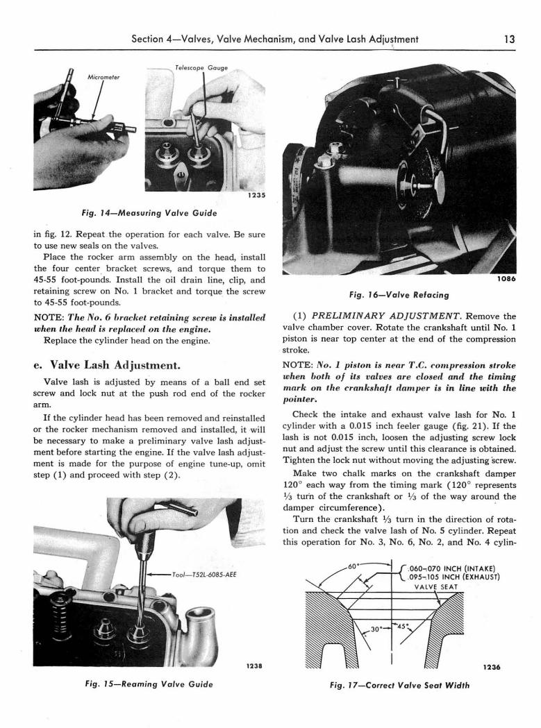
(2) VALVE GUIDE INSPECTION AND REPAIR. Measure the valve guide diameter (fig. 14) .and the valve stem diameter. If the clearance is more than 0.004 inch for the intake or more than 0.005 inch for the exhaust valves, ream out the guide and install the next oversize valve. Use the piloted reaming tool shown in fig. 15. Be sure to clean out all chips and metal particles. Regrind the valve seats when the guides are reamed. NOTE: The valve guide reamer. are piloled to fit a "andard hole (0.003 inch over,i.e. reamer), 0.003 inch oversi.e hole (0.015 inch reamer), and a 0.015 inch oversi.e hole (0.030 inch reamer). Be lUre to use the rea,ners in ,equence when reaming from standard to oversize hole,.
(3) REFACING V ALVES. Grind the valve face at a 45 ° angle on a valve refacing machine as shown in fig. 16. Grind off only enough stock to remove pits or grooves from the valve face. If the edge of the valve head is less than %2 inch thick after grinding, ' replace the valve. Grind the valve stem ends if they are grooved or scored. Do not grind more than 0.010 inch from the stem end. Check the valve face runout. If it exceeds 0.002 inch, regrind the face. If it still exceeds 0.OQ2 inch after regrinding, discard the valves.
(4) VALVE SEAT REFACING. Clean the valve seats with a wire brush to remove all carbon. Clean the
Fig. IO-Cylinder Head Holding Fixture

12 Chapter 1-EAA Series-6-Cylinder Engine
ROCKER ARM MOUNTING COVER RETAINING STUD"", FLAT WASHER
FL A T WASHER , _ \ ,!
SPRING /' WASH ER PLUG ROCK ER SHAFT --- FRONT--- PLUG T265
Fig. 1 '-Rocker Mechanism-Disassembled
valve guides with a guide cleaner. Grind the seats with a valve seat grinder. Remove only enough stock to clean up pits and grooves in the seat. If the valve seat width is more than 0,070-0,080 inch (intake) or 0.095-0.105 inch (exhaust) remove just enough stock from the top and bottom edge of the seat to reduce the width (see fi g. 17). Use a 30° angle wheel to remove stock from the bottom of the seat and a 60 ° angle wheel to remove stock from the top. Keep the seat as near to the center of the valve face as possible.
Check the valve seat runaut with a runaut gauge as shown in fig. 18. The seat runaut should not exceed 0.003 inch.
(5) TEST VALVE SPRING PRESSURE. Check the valve spring pressure with the tool shown in fig. 19. The valve springs should exert a pressure of 54-62 Ibs. when compressed to a length of 1.821 inches or 124-140 Ibs, when compressed to 1.505 inches (A 10% loss in pressure is allowable in service).
c. Rocker Arm, Shaft . and Push Rod Inspection.
Check the rocker arm bore diameter with a telescope gauge and micrometer. Check the rocker arm shaft diameter at the location of the rocker arms. If the
1234
Fig. '2-Removing Valve Stem Locks
clearance between the shaft and rocker arms exceeds 0.007 inch, replace the shaft and rocker arms. Check the rocker arm adjustment screws and lock nuts for stripped threads, and the ball end of the screw for nicks and scratches. Replace any scratched rocker arm screws or lock nuts with stripped threads.
Check the push rods by rotating them between cup and ball centers with a dial indicator on the rod. If the total indicator runout exceeds 0.020 inch) replace the rods. D o not attempt to straighten push rods. Check the ball end and socket ends to make sure they are smooth. If either eRd is nicked or scratched, replace the rod.
NOTE: A. rough check lor ',ent pu.h rorl. can be nlnde while they are installed in the engine. Rotate the push rotls ( valves clo.etl) and oh.erve the run· out. If any runout is oiMervecl be sure to check the push rod with an inclicator 03 tlescrihed above.
d. Cylinder Head Assembly.
Oil the moving parts with engine oil. Layout the shaft and rocker mechanism parts as shown in fig. 11. Install a plug in each end of the shaft, cup side out- Do not peen these plugs to make them tight. Install a flat washer, spring washer, another flat washer, and a cotter pin in one end of the shaft. Install the pa rts in the order shown in fig. 11. Install the screw retaining the shaft to the No, 3 support bracket. An assembled view of the rocker arm, shaft, and bracket is shown in fig. 20.
Install a valve 'in the port from which it was removed. Install the valve spring with the closed coil next to the head. Install the valve spring seat and sleeve. Compress the spring, install the seal, and install the locks as shown
SPRING- 6513 SlEEVE-6517~K-6518
©' t ~(j)cy~ EXHAUST VAl VE_6505 RETAINER -6514 ~Al-6571 INTAKE VALVE-6507 1233
Fig, 13-Valve and Related Parts
Section 4 - Valves, Valve Mechanism, and Valve lash Adjustment •
13
~ Telesco pe Go uge
1235
fig. 14-Measuring Valve Guide
in fig. 12. Repeat the operation for each valve. Be sure to use new seals on the valves.
Place the rocker arm assembly on the head, install the four center. bracket screws, and torque them to 45-55 foot-pounds. Install the o il drain line, clip, and retaining screw on N o. 1 bracket and torque the screw to 45-55 foot-pounds.
NOTE: Tire No. 6 Ilrack et retaining screw is in. taller! when lhe heall is re/Jlnced on "he engine.
Replace the cy linder head on the engine.
e. Valve Lash Adjustment. Valve lash is adjusted by means of a ball end set
screw and lock nut at the push rod end of the rocker arm.
If the cylinder head has been removed a nd reinstalled or the rocker mechanism removed and installed, it wi ll be necessary to make a preliminary valve lash adjustment before sta rting the engine. If the valve lash adjustment is made for the purpose of engine tune-up, omit step (1) a nd proceed with step ( 2).
T oo/- T52L-6085 -AEE
1238
Fig_ J 5-Reaming Valve Guide
Fig . 16-Valve Relacing
( 1) PRELIMINARY ADJUSTMENT. R emove the va lve chamber cover. Rotate the crankshaft until No.1 piston is near top center at the end of the compression stroke.
NOTE: No .1 pis tOll is near T.C. com.pression stroke wlten Ilotlt of its valves are closed and the timing mark on 'he crankshaft tlarnper is in line with the fJointer ..
Check the intake and exha ust va lve lash for No. 1 cylinder with a 0.015 inch feeler gauge (fig. 21 ) . If the lash is not 0.015 inch, loosen the adjusting screw lock nut and adjust the screw until this clearance is obtained. T ighten the lock nut without moving the adjusting screw_
Make two chalk marks on the crankshaft damper 120 0 each way from the timing m ark (120 0 represents V3 turn of the crankshaft or '/3 of the way around the damper circumference).
Turn the crankshaft l!3 turn in the direction of rotation and check the va lve lash of No. 5 cylinder. Repeat this operation for No. 3, N o. 6, No. 2, and N o. 4 cylin-
Fig. 17-Correcl Valve Seat Width

14 Chapter 1- EAA Series-6-Cylinder Engine
TIGHTEN PILOT __ ~ --SET DIAL TO " 0 "
.... 'UI.AIE SLEEVE CLOCKWI SE AND READ
Fig. 18-Checking Valve Seat Runout
clers, turning the crankshaft 1/ 3 turn for each set of valve~.
(2) FINAL ADJUSTMENT. Run the engine until it reaches normal operating temperature, then check the valve lash. The lash should be 0.0 IS inch, and may be
SHAFT RETA""Nr. SCREW
/ FRONT
,/ 1266
Fig. 20-Rocker Arm and Shaft Assembly
checked with the engine idling or with the procedure outlined above. Replace the valve .:::hamber cover with a new gasket cemented to the cover only. Do not exceed 8-10 foot-pounds torque on the cover nuts or the cover will be distorted .
5. OIL PAN, FILTER, OIL PUMP, AND PRESSURE RELIEF VALVE Procedures for repair and replacement of the oil pan,
filter, oil pump, and pressure relief valve are presented here under self-explanatory headings.
a. Oil Pan.
Removal, cleaning, inspection, and installation proce-
_ Valve Spr ing Testing
1263
Fig. 19-Checking Valve Spring Presure
dures for the oil pan are given under descriptive headings. The oil pa n is shown in fig. 22.
(1 ) REMOVAL. Drain the crankcase. Drain the coolant from the engine and the radiator. Disconnect the upper and lower radiator hose at the engine. Remove the bolts which attach the engine front supports to the frame. Raise the front end of the engine about 2 inches.
Pull the dip stick out of the tube. Remove the oil pan retaining screws and remove the pan and gasket.
(2) 'CLEANING. Wash the pan in solvent and dry
Fig . 21-Checking Valve Lash

Section 5-0il Pan, Filter, Oil Pump, and Pressure Relief Valve 15
it thoroughly. Brush any dirt or metal particles from the inside of the pan. Scrape all the old gasket material from the gasket surface of the pan.
(3) INSPECTION. Check the pan for cracks, holes, or warping at the gasket surface. Repair any cracks or holes. Replace the pan if repairs cannot be made.
(4) INSTALLATION. Clean the gasket surface of the block thoroughly. File off any burrs around the threaded bolt holes. Tie the oil pan gasket to the pan with string through two screw holes at each end of the pan.
Hold the pan in place and install one screw, finger tight, at each end of the pan. Remove the string ties and install the remaining screws. Tighten the screws from the center outward in each direction with a large screwdriver. After tightening all screws, recheck the center screws.
Lower the engine and install the front mounting bolts. Conhect the radiator hose and fill the cooling system.
Fill the crankcase with the proper grade and quantity of engine oil. Run the engine until it is warmed up and check for oil leakage and coolant leakage.
h. Oil Filter. The full-flow type oil filter filters the entire output of
the pump before the oil enters the lubrication system of the engine. A built in by-pass provides oil to the system in case. the filter element becomes clogged. The by-pass is built into the hollow center bolt and consists of a spring loaded valve. When the element is clean and oil will flow through it, the pressure difference between the outside and inside faces of the valve is not great enough to overcome the spring pressure behind the valve. When the element is dirty and will not permit a sufficient flow of oil, the pressure inside the center bolt drops and the pressure difference on the valve faces is enough to cause the valve to' open. Oil then by-passes the elem~nt maintaining a supply to the lubrication system.
Oil PAN -6710
Fig. 22-0il Pan
(1) REMOVAL. Place a drip pan on the floor directly under the filter. Remove the through bolt retaining the filter to the block. Remove the filter assembly and gasket.
(2) DISASSEMBLY. Remove the filter element, gasket, spring seat, and spring from the housing. Remove the center bolt a nd fiber gasket. The filter is shown disassembled in fig. 23.
(3) CLEANING. Wash all parts in solvent. Make sure a ll openings in the center bolt a re clean.
(4) ASSEMBLY. Use new gaskets when assembling the filter. Place a new fiber gasket on the center bolt, then install the bolt in the cover. Install the spring, spring seat, new neoprene gasket, and filter element on the bolt. Be sure the seat is fastened to the spring with the tangs.
NOTE: Be sure ,here is only one neoprene gasket. between I.he spring seat and the filter elem.ent. 1/ two gnskets are used, I./, e oilily-pass port may lIe partially covered when the filter element becomes clogged.
(5) INSTALLATION. Install a new gasket in the block recess.
NOTE: Do not r,se any senling cOlnpounds.
Install the filter assembly against the gasket, tightening the bolt just enough so the filter housing touches the gasket. Rotate the housing slightly in each direction to make sure it seats evenly against the gasket. Tighten the center bolt to 20-25 foot-pounds.
Start the engine and allow it to idle until lubrication is fully established, then increase engine speed and check for leaks around the filter. Check the oil level in the cr.ankcase and add oil if necessary.
CAUTION: It is important that th'! filter housing does not leak /,ecause the full output of the oil pump passes through ti,e filter and oil inside the filter i. at t.he sam.e pressure as the lubrication system.
FILTER ElEMENT REPLACEMENT ASSEMBLY
6731 __
CENTER BOLT -66741
SPRING SEAT -6898
SPRING-6889
COVER -6737 ............
FRONT ..........
1278
Fig. 23-0il Filter Disassembled

16 Chapter I-EAA Series-6-Cylinder Engine
c. Oil Pump and Pressure Relief Valve. A gear type oil pump is mounted on the inner side
of the crankcase in line with the distributor. The pump is driven by means of a slot ,in the distributor shaft and a tang on the end of the oil pump shaft. A pressure relief valve is incorporated in the oil pump housing.
Oil pump removal, disassembly, cleaning, inspection, assembly, and installation procedures are presented below. The pressure relief valve is covered in the disassembly and assembly procedures for the pump.
(1 ) REMOVAL. Drain the oil a nd remove the oil pan. Remove the distributor. Remove the two nuts and lock washers retaining the pump to the cylinder block. Remove the pump and gasket.
NOTE: I j the oil pump mounting TJOlts turn in the block, remove the oil filter to gain access to tlte pump mounting fJolt located inside tlte filt er housing, (fig. 24) .
(2) DISASSEMBLY. Remove the screen assembly retaining screws, the screen assembly, and gasket. R emove the cover retaining screws, cover, and gasket. Push the pump drive shaft al'!d drive gear assembly from the pump housing. R emove the driven gear. Remove the oil pressure relief valve plug, spring, and plunger.
Remove the snap wire retaining the pump screen and remove the screen from the housing. The oi l pump and screen are shown completely disassembled in fig. 25.
(3) CLEANING. Wash all the parts in solvent and dry· them thoroughly. Blowout the inside of the pump housing to make sure no dirt or metal particles remain. Remove all old gasket material from the pump body and cover plate.
(4) INSPECTION. Check the pump housing for cracks or excessive wear. The pump shaft should have a free running fit without excessive play in the pump body (0.0005 to 0.0025 inch clearance) . Check the pump
Fig . 24-Location of Oil Pump Mounting Bolts
gear teeth for scratches and wear. Measure the clearance between the outside diameter of the gears and the pump housing. It should be no greater than 0.005 inch. Check the compression of the relief valve spring. It should be 9.82 pounds plus or minus 0.12 pounds when the spring is compressed to 1.56 inches. Replace any worn or defective parts.
( 5) ASSEMBLY. Apply a light coat of engine oil to all moving parts. Place the snap ring on the groove on the upper end of the lower drive shaft. Snap the .tang of the intermediate shaft into the fork of the lower shaft, making certain the snap ring is seated in the groove in both shafts. Slide the drive gear and shaft assembly into the housing. Install the pump driven gear, the cover plate gasket, the cover plate, and the retaining screws. Torque the screws to 10-12 foot-pounds. Install the pressure relief valve plunger, spring, and plug. Tighten the plug to 33-38 foot-pounds.
Install the screen in the screen cover and secure it with the snap wire. Install thb gasket, screen and cover assembly, and retaining screws. T ighten the screws to 10-12 foot-pounds. Rotate the pump shaft by hand to make sure it tUrns freely.
GASKET-bb" · ......
-r~3786.S lOCKWASHER
~-~S9 SCREW _ 6638
34827-8
PLUG-6666~\~I~~:j HaUSING-6604
SPRING_6654
~I i UPPER SHAFT -66646 : ~ I I
6636 : ' \j II DRIYEN GEAR-6614
SHA,( : I i'l ASSEMBl~08 I I
~N2G14-±jl ! A~.,.---::;;:;;~~· , !)-) ., --COYER '4"""""""" GASKET _6619
COYER-6616---, ... <t@jdi1l. ~ .. i,.iii. iii'~oi?; ~~6.8
-~ .~
::~:::~6::1:~ SNAP WIRE_6628~ 1229
STRAINER GASKET -6626
SCREW _ 42848-S
Fig. 25-0il Pump Disasse mbled

Section 5-0il Pan, Filter, Oil Pump, and Pressure Relief Valve 17
(6) INSTALLATION. P lace a new gasket on the retaining bolts and slide the pump mount ing fl ange over the re taining bolts. Insta ll the lock washers a nd nuts. T orque the nuts to 30-35 foot-pounds.
Instali the oil fi lter and the oil pan. Insta ll the distributor. Fill the crankcase with the proper grade a nd quanti ty of oil.
Run the engine to check for proper pump operation.
6. CRANKSHAFT DAMPER The 6-cylinder engine IS equipped with either a
rubber-type damper (fig. 26) or a v iscous damper which is keyed to the cra nksha ft a nd reta ined with a cap screw and washer. Two threaded bolt holes are provided in the da mper to facilitate rem ova l.
a. Removal. R emove the radiator. R emove the generator belt. R e
move the retaining bolt and washer from the end of the cranksha ft. R emove the damper from the crankshaft
with the tool shown in fi g. 27.
h. In stallation. Lubricate the -cra nkshaft with a n oil-white lead mIx
t ure. Line up the da mper ' keyway with the key on the cra nkshaft a nd start the damper on t he sha ft. P ress the damper on t he shaft (fig. 28). Install the washer and re taining bolt a nd torque the bolt to 45-55 foot-pounds. Install the generator belt a nd adjust the belt tension. Install the radiat or.
7. CYLINDER FRONT COVER AND OIL SEAL The engine front cover is a one piece steel stamping
retained to the cylinder block by ten slot ted head screws and to the oi l pa n by two screws. T wo dowels a re used to locate the cover on the block. The igni t ion timing pointer is spotwelded to the cover.
Procedures for cover remova l, inspection, oil seal replacement, and installa tion a re given b elow.
a. Removal. R emove the radiator. R emove the cra nkshaft damper.
Remove the two screws t hat reta in the front end of the
•
1230
Fig . 26-Vibrolion Damper
oil pan to t he cover and loosen the rema ining screws slightly. R emove the cover retai ning screws, the cover, and gasket.
h. Inspection. Check the cover for cracks a nd for dam age to the
gasket surfaces. R epa ir any cracks or replace the cover if repa irs cannot be made.
c. Oil Seal Replacem ent. Drive out t he o ld seal with a p in punch. Clean out
the seal recess in t he cover a nd insta ll a new seal with the tool shown in fi g. 29. Coat the new seal with grease
Fig . 27-Damper Re moving Tool

18 Chapter I-EAA Series-6-Cylinder Engine
to reduce friction when installing. Drive the seal in until it is fully seated in the recess. Check the sea l to be sure the spring did not come out during installation.
d. Installation. Position a new gasket on the block, place the cover
on the cylinder block, and install the retaining screws. Tighten the cover retaining screws evenly. Inste Il the damper. Install the radiator. Install the two screws retaining the oil' pan to the front cover and tighten all oil pan screws evenly working from the center outward in each direction.
8. CAMSHAFf SPROCKET, CAMSHAFf, AND BEARINGS The camshaft is supported by four bearings which are
pressed into the block. It is driven by a sprocket and timing chain in mesh with a sprocket on the crankshaft. An eccentric on the camshaft contacts the fuel pump rocker arm which operates the fuel pump. The camshaft sprocket is keyed to the camshaft and is retained by a bolt and washer. Camshaft thrust is controlled by a plate bolted to the front of the block. The plate is located between the camshaft sprocket and a shoulder on the camshaft.
Procedures for removal, inspection, and installation of the camshaft sprocket, timing chain, camshaft, and bearings are given below. The procedures are written to include the steps necessary for removal and installation when the engine is in the vehicle. If the engine is removed, eliminate a ny steps not applicable. The camshaft and related parts are shown in fig. 30.
a. Camshaft Sprocket and Timing Chain. To make the sprocket and chain accessible, remove
the radiator, crankshaft damper, and engine front cover. (1) INSPECTION. Check the wear on the timing
chain and camshaft sprocket by taking up the slack on the driving side of the chain then measuring the deflection on the slack side of the cha in (fig. 3 1) . Total outward deflection should not be more than 1/ 2 incp. If excessive slack is indicated it will be necessary to re-
Fig. 28-/n51alling Damper
place the sprockets and chain. Check the camshaft sprocket for broken or chipped teeth.
(2) REMOVAL. Before removing the camshaft sprocket, it is advisable to a lign the timing ma rks as shown in fig. 32.
Remove the camshaft sprocket retaining bolt and washer. Slide the camshaft sprocket, timing chain, and crankshaft sprocket forward until the camshaft sprocket comes off the camshaft. D o not lose the key from the camshaft.
(3) INSTALLATION. Place the timing chain over the crankshaft sprocket, and insert the camshaft sprocket in the timing chain so the timing marks of both sprockets and the chain are aligned (fig. 32). Align the key in the camshaft with the camshaft sprocket keyway and slide the assembly into position. Recheck the timing. Install the washer and retaining bolt. Tighten the bolt to 45-50 foot-pounds.
Install the cylinder front-tover, crankshaft damper, and radiator.
b. Camshaft. It will be necessary to replace the camshaft when the
lobes are worn to such an extent that valve lift is less than 0.335 inch for intake and 0.330 inch for exhaust. Check valve lift with a dial indicator as shown in fig. 33. The valve lash must be zero.
( 1) REMOVAL. R emove the grille and radiator. Re-
Fig . 29-/n51alling Oil Seal

Section 8-Camshaft Sprocket, Camshaft, and Bearings 19
CAMSHAFT -6250
1241
Fig. 3D-Camshalt and Related Parts
move. the crankshaft damper and cylinder front cover. Remove the rocker arm cover and the push rod cover. Remove a ll push rods. Lift the tappets and hold them in the up position with spring clothespins or rubber ba nds.
NOTE: If t.he engine is rem.overl frotn the vehicle, invert it to k eep the tappets away from, the camshaft. Be sure oil pan is eith er drained or rentoved 1)elore inverting engine.
Remove the distributor. R emove the fue l pump. Remove the camsha ft sprocket a nd timing chain. Remove the screws retaining the thrust plate a nd remove the thrust plate. Carefully pull the camshaft out of the engine.
CAUTION: Do not gouge the camshaft bearing. with the cam [olles when relf1.ov ing the camshaft.
(2) INSPECTION. Check the camshaft journals
ESTABLISH STRAIGHT PBm~~N SHOWN IN DOnED 0
UP SLACK ON DRIVING SIDE AND MEASURE SLACK SIDE.
Fig. 3J-Checking Timing Chain Deflection
1355
Fig. 32-Aligning Timing Marks
for grooves or scratches. Measure the journa l diameter for wear and out of round. R eplace t he camshaft if the journa ls are more than 0.001 inch out of round. M easure the front camshaft bearing inside diameter . The difference in measurement between the bearing and camshaft journal (amount of clearance) should be .0 . .0.01-.0 . .0.03 inch for a new camshaft a nd bearings, and not over .0 . .0.05 inch fo r a used camshaft and bearings. If the front bearing is worn excessively, it can be assumed that all bearings are worn to this extent.
Check the fuel pump eccentric for wear. Inspect the distributor drive gear for worn or damaged-teeth.
Replace the camshaft or bearings if any of the above conditions exist.
Inspect the wear pattern on the lift portion of the cam lobes. The surface of the cam is tapered slightly to aid in tappet rotation. If the taper is worn off over more
Fig . 33-Valve Liff Measuremenf

20 Chapter l- EAA Series-6-Cylinder Engine
than ha lf the face of the ca m, the cam sha ft must be replaced.
,(3) INSTALLATION. Slide the camsha ft carefully into the bearings. Install the thrust p late and secure it with the retaining screws. T ighte n the screws to 15-18 foot-pounds. Check the camshaft end play. It should be 0.003-0.006 inch. Install the camsha ft sprocket, timing chain, fro nt cover, a nd cra nkshaft da mper. Install the generator belt a nd adj ust belt tension. R e lease the tappets and install the push rods. M a ke a n initial adjustment of the valve lash.
Insta ll the distributor a nd adj ust the initial timing. Insta ll the fuel pump. I nsta ll the tappet cha mber cover and torque the reta ining screws to 8-10 foot-pounds. Install the radiator and grille. W a rm up the engine and check the valve lash with the engine idling. R eset the lash, if necessary. Install the rocker a rm cover a nd torque the nuts to 8-10 foot-pounds.
c. Camshaft Bearing Replacem ent. R eplace camshaft bea rings if the cleara nce exceeds
0.005 inch.
It will be necessary to remove the engine from the vehicle to replace camshaft bearings. The bearings are available pre-finished to size for sta ndard and 0.015 inch undersize camshaft journa l diameters.
Fig . 35-Removing or Installing Camshaft Bearings
The bearing insert for N o. 1 bearing is not interchangeable with the No.2, 3, and 4 bearings.
( 1) REMOVAL. R emove the camshaft. Drill a 1/ 2"
ho le in the plug at the rear camshaft bearing bore. Use the tool shown in fig. 34 to remove the plug. R emove the camshaft bearings with the tool shown in fig. 35.
(2) INSTALLATION. Position the bearing at the bearing bore and press it in place as shown in fig. 35. Be sure the oil hole in the bearing lines up with the oil hole in the bore.
Clean out t he plug recess in the rear bearing bore. Coat the rim of a new plug lightly with sea ler. Install the plug with the tool shown in fig. 36. Install the camshaft.
9 . FLYWHEEL, CRANKSHAFT, AND BEARINGS Procedures for removal, inspection, and replacement
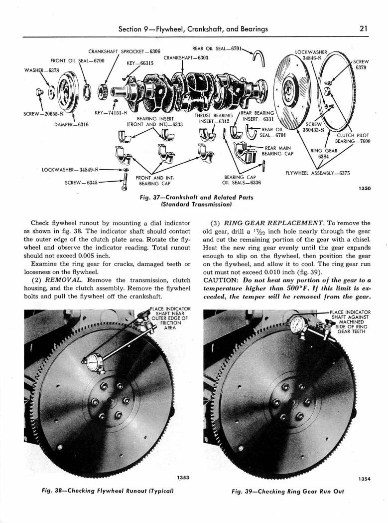
of the fl ywheel, cranksha ft, a nd bearin gs are covered here under headings descriptive of the operation. The cranksha ft and related parts a re shown in fig. 37.
a. Flywheel. The rear face of the flywheel is used as a friction
surface which is engaged by the clutch plate. The flywheel ring gear is secured to the flywheel by mea ns of
Fig. 34-Removing Camshaft Bore Plug
a shrink fit.
( 1) INSPECTION. Flywheels having a burned or scored fr iction surface should be replaced.
CYLINDER SLOCK CORE ",l"" 'oq
Fig. 36-lns,alling Camshaft Bore Plug
Section 9-Flywheel, Crankshaft, and Bearings 21
REAR Oil SEAL-6701~
CRI,NKSHAH_6303 • U 6379
DAMPER-6316 BEARING INSERT
~:l'1:1
LOCK WASHER- 34849·S , ..,
SCREW-634r.4 FRONT AND INT.
BEARING CAP BEARING CAP
OIL SEALS-G336
PILOT BEAI~INC;-7600
FLYWHEEL ASSEMBLY -6375
1350
Fig. 37-Crankshafl and Relaled ParIs (Standard TransmissionJ
Check flywheel run out by mounting a dial indicator as shown in fig. 38, The indicator shaft should contact the outer edge of the clutch plate area, Rotate the flywheel and observe the indicator reading. Total runout should not exceed 0,005 inch.
Examine the ring gear for cracks, damaged teeth or looseness on the ft.ywheel.
(2) REMOVAL. Remove the transmission, clutch housing, and the dutch assembly. Remove the fiywhep. i bolts and pull the flywheel off the crankshaft,
.~,,~, • • INDICATOR SHAFT NEAR
OUTER EDGE OF FRICTION
AREA
1.353
Fig. 38-Checking Flywheel Runoul (Typical!
(3) RING GEAR REPLACEMENT, To 'remove the old gear, drill a 1 'lb inch hole nearly through the gear and cut the remaining portion of the gear with a chisel. Heat the new ring gear evenly until the gear expands enough to slip on the flywheel, then position the gear on the flywheel, and allow it to cool. The ring gear run out must not exceed 0,010 inch (fig, 39), CAUTION: Do not '. ent any portion of the gear to a temperature higher Ilwn 500 0 F. If this limit. is eXa ceeded, the temper will ',e re,novetl fro,n the gear.
Fig. 39-Checking Ring Gear Run Oul

22 Chapter I-EAA Series-6-Cylinder Engine
(4 ) INSTALLATION. Place the flywheel on the crankshaft flange and install the mounting screws. Torque the screws in sequence across from each other to 75-85 foot-pounds. Install the clutch assembly, clutch housing, and transmission.
b. Crankshaft.
The crankshaft is made of cast nodular iron with integral counterweights and is statically and dynamically balanced. Oil distribution holes are drilled through the shaft to pressure lubricate the main and connecting rod bearings.
(1) REMOVAL. Remove the engine and install it on a work stand. Remove the flywheel housing, clutch assembly, starter, and engine Tear plate assembly. Remove the flywheel. Remove the damper, front cover, camshaft sprocket and timing chain. Remove the oil pan and the oil pump screen housing assembly.
M ake sure all bearing caps aTe marked so they can be reinstalled in exactly the same position. Remove all connecting rod bearing caps and bearings. Remove the main bearing caps and bearings. Mark all bearings so they can be installed in the same location from which they were removed. Remove the crankshaft. Be careful not to damage the thrust bearing.
(2) INSPECTION. Examine the shaft for cracks. Make sure the dowel pins (Fordomatic only) in the flange are not .loose or damaged. Grooved or scored main
Fig. 40-Beoring Scratched by Dirt
or crankpin journals will cause bearing failure and should be reground for undersize bearings. Remove light scores or scratches with an oilstone, then polish with No. 320 grit polishing paper.
(3)' MEASURING CRANKSHAFT JOURNALs. Measure each journal at a minimum of four places to determine size, out of round, and taper. Journals that are out of round more than 0.0015 inch or have more than 0.001 inch taper should be reground. Standard crankshaft journal diameters are: 2.4980-2.4988 inches for main journals and 2.2980-2.2988 inches for crankpin journals.
(4) REGRINDING CRANKSHAFT. If it is neces'sary to regrind the crankshaft, select the next undersize bearing and regrind the journals to give 0.0005-0.0021 inch clearance in the bearings. If it is necessary to regrind the journal diameter more than 0.030 inch, discard the crankshaft.
Always grind the same radii at the ends of the journals as the shaft had originally. Too small a radius will cause fatigue failure ~f the crankshaft; too large a radius causes bearing failure due to "radius ride" of the bearing.
Use No. 320 grit polishing paper and engine oil to polish the journal after grinding.
(5 ) INSTALLATION. Be sure that all bearing inserts, bores, and the crankshaft journals are clean. Apply a light coat of engine oil to the journals and bearing inserts: Install the inserts in the, block. Carefully lower
Fig. 4J-Fatigue Failure of Bearing
Section 9-Flywheel, C(ankshaft, and Bearings 23
the crankshaft into the bearings. Be careful not to damage the thrust bearing surfaces.
Install the main bearing inserts in the cap,s and install the caps in the block. Install cap bolts fi nger tight, pry the crankshaft forward to align the thrust bearing faces, and tighten a ll bearing cap bolts to 95-105 foot-pounds.
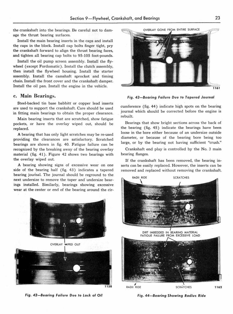
Insta ll the oil pump screen assembly. Install the flywheel (except F ordomatic). Install t he clutch assembly, then install the flywheel housing. Install the starter assembly. Install the camshaft sprocket and timing chain. Insta ll the front cover and the crankshaft damper. Install the oil pan. I nsta ll the engine in the vehicle.
c. Main Bearings. Steel-backed tin base babbitt · or copper lead inserts
are used to support the crankshaft. Care should be used in fitting main bearings to obtain the proper clearance.
M ain bearing inserts that are scratched, show fatigue pockets, or have the overlay wiped Qut, should be replaced.
A bearing that has only light scratches may be re-used providing the clearances are satisfactory. Scratched bearings are shown in fig. 40. F atigue failure can be recognized by the bre~king away of the beari ng overlay materia l ( fig. 41 ). Figure 42 shows two bearings wit h the overlay wiped out.
A bearing showing signs of excessive wear on one side of the bearing half (fig. 43) indicates a tapered bearing journa l. The journal should be reground to the next undersize to remove the taper and undersize bearings installed. Similarly , bearings showing excessive wear at the center or end of the bearing around the cir-
Fig . 42-Bearing Failure Due 10 Lack of Oil
Fig . 43-Bearing Failure Du e to Tap ered Journal
cumference ( fi g. 44 ) indicate high spots on the bearing journal which should be corrected before the engine is rebuilt.
Bearings that show bright sections across the back of the bearing ( fi g. 45 ) indicate the bearings have been loose in the bore either because of an undersize outside diameter, or because of the bearing bore being too large, or by the beafing not having sufficient "crush."
Crankshaft end play is controlled by the No.3 main bearing flanges.
If the crankshaft has been removed, the bearing in· serts can be easi ly replaced. H owever, the inserts can be removed and replaced without removing the crankshaft.
RADII RIDE SCRATCHES 1162
Fig . 44-Bearing Showing Radius Ride

24 Chapter 1- EAA Series-6-Cylinder Engine
NOTE: S pecial care must he ,aken when installing I,he re(lr main /)caring cap 10 prevent oil leakage past tlte twu sets 0/ .'wals. Use the procedure presenled under "(5) Replacing Rear· Oil Seals" when I.he cap is installed. .
(1) REPLACEMENT WITHOUT REMOVING CRANKSHAFT. After the bearing cap has been removed, a special tool designed for removing the upper bearing insert may be inserted in the oil hole in the crankshaft. Figure 46 shows the tool in position ready to bear against the insert. When the crankshaft is ro~
t ated in the direction opposite to engine rotation the tool will force out the bearing insert. This tool should be used with caution to avoid d amaging the bearing.
T o install the upper main bearing insert, .place the plain end of the bearing over the locking ta ng side of the shaft. Using the same tool, rotate the crankshaft in the direction of engine rotation until the bearing seats itself.
(2) FITTING MAIN BEARINGS (PLASTIGAGE METHOD) . If the engine is removed from the vehicle, drain the oil, remove the oil pan and invert the engine. R emove the bearing cap a nd wipe the oi l from the bearing and journal. Keep the other bearing caps tight while checking the fit of a bearing.
NOTE: If Ihe bearing fit is checked while Ihe engine is in the vehirle it will lie necessary to support the weight of the crnnksllflfl._ The shaft can be supporled fJY placing (l thin rullber pad fl etween the cap insert
and journal of lwo IMarings that are not llcing checked. Tighlen Ih esc I,caring cap IJOlts enough 10
hold the crankshafl up against Ihe Mock half of Ihe
main llearing inserts.
BRIGHT IPO"""O) SECTIONS
Fig. 45-Bearing Showing Bright Spots Due To Improper Seating
Fig. 46-Removing Main Bearing Inser'
Place a piece of Plastigage the full width of the bearing on the journal (or in the bearing cap). Install the bearing cap and tighten the retaining 1;lOlts to 95-105 footpounds.
CAUTION: Do nol lurn the crankshaft while the Plastigage is IJetween the IJearing anll the journal.
Remove the bea ring cap. Without moving the plastic, check its width (at the widest point) with the graduations on the Plastigage container as shown in fig. 47.
NOTE: Normally, main bearing journals wear evenly and are not out·of·round. However, if a bearing is Ileing fitted to an out·of-rounel journal, be sure to fit tlte I) earing to the rnaxim~m diam.eter of the journal. If the IJcari,ig is fitt ed to tlte minimum clearance of 0.0005 on the minimluti rlia,neler of the journal, and Ihe journal is oul-of-round 0_0005 or ,narc, inler Jerence IJetween lhe j~urnal and bearing will result in rapid failure of th e /Jearing.
If the bearing clearance is not over 0.0021 inch or less than 0.0005 inch, the bearing insert is satisfactory. If the clearance is not within limits, try the selective
Fig . 47-Measuring Flattened Plastigage

Section 9-Flywheel, Crankshaft, and Bearings 25
REAR MAIN BEARING CAP
JOURNAL OIL
1267
Fig. 48-Rear Bearing Cap Seals
fit bearing to bring t he clearance within the 0.0005-0.0021 inch limit. If the selective fit bearings do not bring the clearance below 0.0021 inch, it will be necessary to regrind the crankshaft journals for use with the next undersize bearing.
NOTE: If the flatt ened plastic is not uniform in width from end to end, the journal or (J caring is tapered. Be sure to check the jo urnal with nlicrometers if th e flattened plastic indicates nwre than 0.001 inch difference.
(3) CHECKING CRAN KSHAFT END PLAY. To check the cranksha ft end p lay, push the crankshaft toward the rear of the e ngine. Place a dial indicator against the rear side of the crankshaft flange. Set the dial to .zero, the n push the crankshaft forward.
If the dial indicator shows more than 0.008 inch or less than 0 .004 inch play! the main thrust bearing insert should be replaced with a new insert to obtain proper end play. The manufacturer's crankshaft end clearance is 0.004-0.008 inch.
TooI- T52l.670 1.AC;O--::::::::::tI
WITH EDG E OF TOOL 1268
Fig . 49-Forming and Cutting Oil Seal
Fig. 50-In stalling Re ar Be aring Cap
(4) REPLACING REAR OIL SEALS. The rear main bearing cap contains the lower crankshaft journal oil seal a nd the cap itself is sealed to the block by two tapered vertical seals (fig. 48) .
Be sure to use the seal forming tool and the bearing cap guide fixture when installing; the seals and cap.
Remove the crankshaft. Remove the rear bearing inserts. Pry out the old seals from the rear bearing cap and block. Clean the seal grooves thoroughly.
Install a new journal oi l sea l in the bearing cap groove. Form the seal and cut it off flush with the edge of the tool as shown in fig. 49. Use a sharp knife and
leave no ragged edges. Repeat the procedure to form the upper half of the
seal in the cylinde r block groove. Install the bearing inserts. Lay the crankshaft in the block bearing halves, using care not to damage the thrust bearing fl anges.
Install the. bearing cap with seals into the fixture. The seals must be even with the parting edge of the cap.
Fig . 51-Che cking Seal for l eakage

26 Chapter I-EAA Series-6-Cylinder Engine
Install the pilot studs in the block. Place the bearing caps and fixture assembly on the pilot studs and slide the bearing cap over the studs and through the guide (fig. 50). Press the bearing cap carefully into place. Coat the surfaces lightly with grease to reduce friction during installation.
NOTE: Be sure Ihe cap to block seals do not shift while the cap is presset! home. The seal must be .eatet! all the way t!own to prevent oil leakage at the parting ·edge of the cap and I,lock. The vertical cap to /,lock seals should extent! approximately 3 /64
inch above th e block to insure a good seal against the oil pan gasket.
Install the bearing cap bolts and torque them to 95-105 foot-pounds.
Check the cap to block seals by applying oil to the outer edges of the bearing cap. Apply compressed air to the corners of the cap inside the' block (fig. 51) and check the oil at the outside edge for bubbles. If any bubbling is apparent, it will be necesary to remove the cap and reinstall it, making sure the cap to block seals seat all the way to the corner of the cap.
10. CONNECTING RODS, PISTONS, AND RINGS This section gives the removal, inspection, and instal
lation procedures for connecting rods, pistons, and pins. Complete data is given on the fitting of all bearings and the fitting of new rings and pistons.
a. ~emove Piston and. Connecting Rod Assemblies.
Remove the oil pan and cylinder head. Before removing a piston from the engine, remove
any ridges that may be present along the upper part of each cylinder as follows :
Move the piston to the bottom ot" its travel and place a cloth on the piston head to collect the cuttings. Position the ridge remover in the cylinder' and adjust the ridge remover pilot to the cylinder size. Make sure the cutter is at the top side of the roller bar and that the cutter does not extend beyond the roller. Make sure the ridge remover shoes are tight. Hold the ridge remover
Fig. 52-Removing Cylinder Ridge
tightly against the block and turn the arbor clockwise with a tee handle wrench ( fig. 52 ) . CAUTION: Never cut into the ring travel area more than 1/ 32 inch when re lnoving ridges.
. Remove the ridge remover from the cylinder bore. Turn the crankshaft until the piston is at the top of its stroke and carefully remove the cloth with the cuttings from the piston head. Clean the carbon from the piston head and cylinder block before removing the piston from the bore.
Turn the crankshaft until the rod of the piston being removed is down. Remove the nuts from the connecting rod bolts. Lift the rod bearing cap from the rod and push the rod and piston assembly out of the top of the cylinder with the handle end of a hammer. Do not scratch the crankpin or the cylinder wall when removing the ,piston and rod. Repeat this procedure for each assembly.
NOTE: Bach ro rl (lnt! bearing cap is numl,ered from 1 10 6 lleginning at the tintin g gear end 0/ the en· gine. Th e nu",l,en on Ih e rod and bearing cap mUll be on the som e side when re-installing them into
EXPAND RING BY CATC HING TIPS OF TOOl
IN RING ENDS
1272
Fig. 53-Removing Rings

Section 1 O-Connecting Rods, Pistons, and Rings 27
Tool- T52L-6 J 35-DED
1273
Fig. 54-Removing Piston Pin
their respective cylinder bores. If a connecting rod i, ever transposed from one /)iock or cylinder to anot.h er, make sure all the bearings nre new and that the nu,nber on the rod is reslarnped to correspond with tire new cylinder nU1nber.
b. Disassembly of Piston and Connecting Rod Assemblies.
M ark the pistons for identification of the piston with the bore and rod for assembling purposes.
R emove the piston rings with the tool shown in fig. 53. R emove the piston pin retainer$. at each end of the piston pin. Drive the piston pin out of the piston (fig. 54).
R emove the rod bearing cap and the bearing inserts after identifying the inserts for reassembly with the same rod and cap, if the inserts are to be fe-used . The piston and rod is shown disassembled in fig. 55,
PISTON RING 6149
CONNECTING ROD ASSEMBLY 6200
r'----------~~,----------" BOLT BEARING CAP NUT
.. ~. "Lib")} ~ BU SHING LOCK NUT
PISTON ASSEMBL Y /_ ..... -\..11' PIN-6135
6207 45218.S
6108 RETAINER-6140 1250
Fig. 55-Piston and Connecting Rod
Groove Cleaning Tool
1251
fig . 56-Cleaning Ring Grooves
c. Cleaning Piston and Connecting Rod Assemblies.
Clean the piston ring grooves with a flng groove cleaner (fig. 56).
Clea n all the parts and passages in solvent. Never use caustic cleaning solution. Thoroughly clean the rod bore a nd the back of the inserts.
d. Inspection of Piston and Connecting Rod Assemblies.
Connecting rod bolts or nuts with damaged threads, and rods with d eep nicks, signs of fractures, scored bore, or bore out of round more than 0.002 inch should be replaced.
Use a new piston pin to check the piston pin bushing in the connecting rod for wear, The pin should have a 0.0001-0.0003 inch clearance in t he rod bushing. If the new pin falls through the bore by its own weigh't , ream the bushing for the next oversize pin or replace the connecting rod.
Check every connecting rod for a lignment on a fixture after fitting the piston pins (fig. 57). If the rod is twisted more than 0.012 inch or bent more than 0.004 inch, it should be straightened or replaced.
ROTATE PISTON AND OBSERVE INDICAT" O;.,R _ __ r
Fig. 57-Check Connecting Rod Alignment

28 Chapter '1- EAA Series-6-Cylinder Engine
( 1) CONNECTING ROD BEARINGS. Replace bearing inserts that are scored, have the overlay wiped oyt, show fatigue failure, or a re badly scratched (fig, 40 through 45).
Install the bearing inserts in the cap and rod section. The bearing should snap into place and remain there. If the bearing slides in freely and will fall out readi ly, the bearing has lost its spread and should be replaced. Check the inside edge of the bearing at the parting line for sharp burrs. Remove the burrs if any are apparent. The parting edges ? f the bearings should be free of dirt or other foreign particles.
(2) PISTONS. Inspect pistons for fractures at the ri ng lands, skirt, and pin bosses. Replace pistons showing signs of excessive skirt clearance, wavy ring lands, fractures, or damage from detonation. Spongy eroded areas near the edge of the piston top are caused by detonation. In some instances holes are also burned through the piston top.
(3) PISTON PINS. R eplace piston pins showing signs of fractures or etching. Piston pins that show wear or fit loose in the piston or rod bushing should be replaced. Replace all piston pin retainers.
(4) CYLINDER BLOCK. M ake a thorough check for cracks. Minute 'cracks not visible to the naked eye may be detected by coating the suspected area with a mixture of 25% kerosene and 75% light motor oil. W ipe the part dry and immediately apply a white coating of zinc oxide dissolved in wood alcohol. ·If cracks are present, the white coating will become discolored at the defective area.
Inspect the cylinder bores for scoring. Inspect the expansion plugs for rust at the edge of the plug, Rust indicates leakage. If leakage is indicated, drill a 1/2"
hole in the plug, then remove the plug with the tool shown in fig, 34. Insta ll a new plug with the tool shown in fig. 36, Always use a sealer when installing new plugs or leakage may result.
• Telescope Gauge 1254
Fig. 58- Measuring Cylinder Bore
Check the cylinder bore for taper, out of round, and wear with a cylinder bore gauge, te lescope gauge, o~
_ inside micrometers. Only experienced personnel should be permitted to take these measurements.
Record measurements taken lengthwise and crosswise at the top and bottom of the block as follows :
Lengthwise of the block, measure and record as "A" the diameter of the cylinder a t the top of the cylinder where the greatest ring wear occurs. Also lengthwise of the block, measure !.. and record as "B" the cylinder diameter at the bottom of the piston skirt travel. Crosswise of the block, measure and record as "C" the diameter of the top of the cylinder at the greatest wear point. Measure and record as "D " the diameter at the bottom o f the cylinder bore, also crosswise of the block.
Reading "A" compared to reading "B " and reading "C" compared to reading "D " indicates cylinder taper. If the taper is greater than 0.015 inch the cylinder must be rebored and honed for the next oversize piston. However, a cylinder rebore should be recommended if the cylinder taper exceeds 0.008 inch.
Reading "A" compared to reading "C" and reading "B " compared to reading "D" indicates whether or not the cylinder is out of round. If the out of round exceeds 0.003 inch, the cylinders must be rebored and honed for the next oversize piston.
Measuring the cylinder bore with a telescope gauge is illustrated in fig. 58.
e. Fitting Pistons. Proper assembly to lerances of pistons are required if
satisfactory engine operation is to be obtained. Cylinder bores must be checked for taper and out of round condition before fitting a piston.
Before installing a piston and new rings in 9 used block, remove the high polish on the cylinder wall to aid ring seating by passing a hone or giaze rernov.ing tool through the cylinder bore a few times. Do not hone more than enough to rough up the polish. Make sure that oi led rags are placed in the bore to catch the hone grit a nd that the cylinder is thoroughly cleaned before installing the piston.
To fit a new piston in a new bore, attach a tension scale to the end of a feeler ribbon 1/2 inch wide and having the correct feeler ribbon thickness as given in Table 1.
Ta ble I-Piston Filling Specillcations
Fit N ew Piston F it New Piston Fit Used P iston In New Bore In Used Bore In Used Bore
Gauge Gauge Gauge Thickness Pounds Thickness Pounds Thickness Pounds
(Inch) . Pull (Inch) Pull (Inch) Pull
0,0015 5-10 0.002 5-10 0.003 5-10

Section 1 O-Connecting Rods, Pistons, and Rings 29
Position the feeler ribbon on the side of the piston 90° from the piston pin hole. Invert the piston, then push t he piston and feeler gauge in the cylinder so the end is about V, inch below the top of the block. Keep the piston pin bores parallel with the crankshaft axis. Pull out the feeler gauge while noting the scale reading (fig. 59 ) .
The pull limits for new pistons and used pistons in new or used bores is given in Table 1.
If the scale reading is greater than the maximum allowable pull, try another piston or hone the cylinder bore to obtain the proper fit. If the scale reading is less than the minimum a llowable pull, try another piston. If none can be fitted, rebaTe the cylinder to the next over size piston.
f. Boring Cylinder Block. To assure maximum engine performance and balance
of the reciprocati ng pa rts of the engine, all cylinders must be bored to the same size when the 0.060 inch piston must be insta lled even though only one cylinder requires reba Ting a nd the others are within tolerance. Manufacturers recommendations on how to use boring equipment should be followed and the work performed only by experienced personnel.
Bore the cylinder with the most wear first to determine tHe proper oversize. If the cylinders will not clean up at 0.060 inch oversize, the block must be replaced.
Whep reboring the cy linders allow 0.0015 inch stock for honing to a fina l finish. Use a number 220 to 280 grit hone for this operation.
Piston Pull Scol.
Thicknen Gouge
F;g. 59-Fi"ing Piston
CAUTION: Thoroughly clean Ihe block 10 remove all particle! 0/ abrasive alter the honing operation.
g. Fitting Piston Pins. Check the piston pin fit in the piston. P iston pins
must be a hand-push fit in the piston pin bore at norma l room temperature (70°F.).
If oversize piston pins are to be used) or if the piston pins sre too tight, ream the pin bore with an expansion type piston pin bore reamer. P lace the reamer in a vise and revolve the piston aroun~ the reamer.
Set the reamer to the size of the piston pin bore, then expand the reamer very s lightly a nd tria l ream the bore in the piston using a pilot sleeve of the nea rest size to maintain alignment of the piston pin bores.
CAUTION: Take a very light cuI.
Check the reamed hole size using the new piston pin to be used in the piston being reamed as a gauge. If the bore is small, expand the reamer slightly and make another trial cut. Repea t the procedure outlined un,til a piston pin fit is obtained.
Similarly ream all the pistons in which pins need to be fitted, checking each with the pin to be used in the piston. Repeat the procedure to fit the pins to the connecting rod bushings.
h. Fitting Piston Rings. Install the piston ring in the cylinder bore. Invert the
piston and use the top to push the ring a bout halfway into the bore to true the ring with the cylinder bore. Measure the ring gap wi th a feeler gauge. The gap should be 0.007-0.047 inch (all rings). If the gap is less than the minimum limit, remove the ring and file the ends until the prope r cleara nce is obtained.
After the rings have bee n fi tted in the cylinder bore, they should be installed on the piston or ident ified with
Fig . 60-Checking Ring Clearance

30 Chapter I-EAA Series-6-Cylinder Engine
the piston and cylinder bore in which they are to be installed.
Check the ring to groove clearance with the rings to .be used on the piston as shown in fig. 60.
The rings should have the following clearance: Clearance in
Piston Groove Ring (inch)
Top Compression . . ... ....... •. . ... 0.0020-0.0035 2nd Compression ... . .. .. . .. ....... 0.0015-0.0030 Oil Ring .... . ........... . ......... 0.0010-0.0025
Three different type rings are available in sets for service, the standard ring, the expander ring, and the steel section ring.
The standard· (snap type) is designed for use in a new engine.
The expander type is designed for use, after a light honing operation, in a cylinder bore with a small amount of t~per, to correct an oil consumption condition.
The steel section type ring should be used in cylinders where the taper of the cylinder bore is very great, or to correct excessive oil consumption conditions when the customer does not want the cylinders rebaTed.
Bore "glaze" should be removed to aid piston ring seating.
i. Fitting Connecting Rod Bearings (Plastigage Method).
Place a piece of Plastigage plastic the length of the insert in the bearing insert. Install the cap and tighten to 45-50 foot-pounds.
NOTE: Do not turn the crankshaft with Pla.tigage in place.
Remove the bearing cap and use the Plastigage scale to measure the width of the flattened piece of plastic at the widest point.
NOTE: If the crankpin is out-of-round, be lUre to fit the 11earing to the maximum diameter 0/ the crankpin. 1/ the bearing i8 fitt ed 10 the minimum diameter 0/ the crankpin with minimum clearance of 0.0005 inch and the crankpin i. out-of·round 0.0005 or more, interference will re.ult in rapid failure of the I,earing.
If the reading is not over 0.0021 inch or not less than 0.0005 inch, the fit is satisfactory. If the clearance is greater than 0.0021 inch, try another selective fit bearing to bring the clearance within the 0.0021 inch limit. If the clearan ce is still excessive, regrind the crankshaft and install undersize bearing inserts.
NOTE: If the flattened pla.tic i. not uniform from end to end in its width, the journal or bearing" u tapered. Be sure to check the journal with microrn-
eters for taper i/ the flattened plastic indicate. more than 0.001 inch (lijj'erence.
Rotate the crankshaft after the bearing is installed to be sure the bearing is not too tight.
j. Assembly. Lubricate all parts with light engine oil.
NOTE: The oil squirt hole should be toward the valve side of the cylinder bore when a.~embly i. installed.
Position the connecting rod in the piston and push the pin into place.
Insert new piston pin retainers by spiralling them into the piston with the fingers. Do not use pliers. Install the piston rings.
Insert the bearing halves in the rod and cap.
k. Installation. Oil the cylinder wall with light engine oil. Make sure
the ring gaps are equally spaced around the circumference of the piston. Compress the rings with a compressing tool and push the piston down with" a hammer handle (fig. 61) until it is slightly below the top of the cylinder.
NOTE: Install ~he piston wilh the indentation in the piston 'lead toward the front of the engine.
Turn the crankshaft throw to the bottom of its stroke. Oil the crankpin and push the piston all the way down until the rod bearing seats on the crankpin. Be careful not to scratch the cylinder bore or the crank pin. Install the bearing cap (line uP. the stamped numbers) and tighten the retaining nuts to 45-50 foot-pounds torque. Install new pal nuts and tighten the nuts to 3-3'/2 footpounds torque (or finger tight plus '/3 turn).
INSTAll PISTON WITH INDENT A TlON TOWARD
I
Fig. 6' -Installing Piston

Section 1 O-Connecting Rods, Pistons , and Rings 31
Install the oil pan and cylinder heads. Fill the crankcase with the proper grade and amount of lubricant. Fill the cooling system. Start the engine and Tun it at idle
speed. Make sure there is sufficient oil pressure. Check the temperature to make sure the engine does not overheat.
II . EXHAUST SYSTEM The exhaust system on the 6-cylinder car consists of
a muffler, an exhaust outlet pipe, and a muffler inlet pipe (fig. 62).
The following procedure covers the removal and installation of units of the exhaust system.
NOTE: After replacing any part of the· exhaust sys· tern, it is advisable to loosen all the frame attaching bracket clamps to relieve twists in the system and then retighten the clamps.
a. Muffler Replacement. Extra heavy, double-wall construction mufflers are
available for service. ( 1) · REMOVAL. Loosen muffler inlet and outlet pipe
clamps. Slide clamps away from the muffler, the inlet pipe, and the outlet pipe. Loosen front and rear outlet pipe clamps and disengage the outlet pipe from the muffler by sliding the outlet pipe to the rear. Remove the muffler from the inlet pipe.
(2) INSTALLATION. Place the muffler in position on the inlet pipe and slide the outlet pipe into the muffler. Place the inlet pipe a nd outlet pipe clamps in position on the muffler and tighten clamps. Tighten the front and rear. outlet pipe clamps.
h. Outlet Pipe Replacement. The outlet pipe is attached to the frame by flexible
sound deadening materials which not only prevent the exhaust noises from being conducted through the chassis
frame but also relieve the exhaust system from twisting or bending stresses.
( 1) REMOVAL. Loosen · the muffler outlet pipe clamp, leaving the clamp on the muffler. Remove the outlet pipe front and rear support clamps and disengage the outlet pipe from the muffler.
(2) INSTALLATION. Position the outlet pipe in the muffler a nd tighten the clamp. Place the outlet pipe rear support bracket clamp on the outle t pipe. Install the front support bracket clamp and tighten the nut. Position the rear outle t pipe clamp on the rear bracket and tighten the nut.
c. Inlet Pipe Replacement. The muffler inlet pipe is designed to give the exhaust
gases leaving the exhaust manifolds a direct through passage to the muffler) thereby increasing the over-all efficiency of the exhaust system.
( 1) REMOVAL. Loosen the muffler inlet pipe clamp. Remove the two nuts holding the inlet pipe to the exhaust manifold) then remove the gasket. Disengage the. inlet pipe from the muffler by sliding the inlet pipe forward.
(2 ) INSTALLATION. Place the inlet pipe in the muffler. Install a new gasket on the exhaust outlet flange studs. Slide the inlet pipe flange over the studs and secure the pipe to the exhaust manifold with the two nuts and lockwashers. Tighten the nuts to 23-28 footpounds. Tighten the muffler inlet pipe clamp.
Fig. 62-6-Cylinder Exhaust System


![Registration of Marriages Ordinance 1952 [53 of 1952]](https://img.pdfslide.net/doc/110x75/55cf85fc550346484b936752/registration-of-marriages-ordinance-1952-53-of-1952.jpg)