Embed Size (px)
Citation preview
inside_color_pages_hardware_catalog2012:Layout 1 6/25/2012 12:59 PM Page 3
I
(800) 253-5668www.rwhardware.com
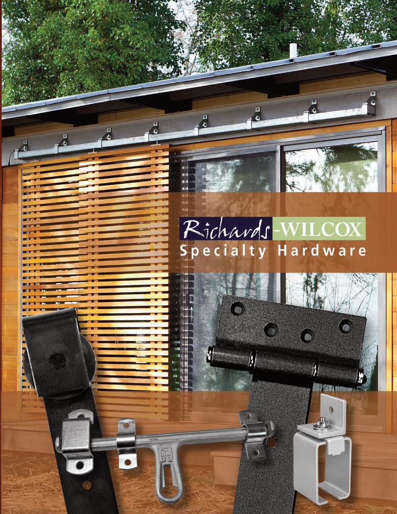
STANDARD OF THE INDUSTRY
Manufacturing since 1880 in Aurora, IL .....................most experience in the industryStandard capacities up to 5000 pounds ..................... heaviest in the industryStandard 10 Year Warranty .......................................... longest in the industryStandard Industrial Strength ....................................... highest quality designs
COMPLETE PRODUCT LINE
Six Track designs and capacities to cover all applicationsStandard Capacities: 400, 600, 800, 1000, 2500, and 5000 pound Construction: 16 gauge to 3/16” Finishes : Bare, Powder Coated, Galvanized, Stainless, or PlatedConfigurations: Curves, Switches, Turntables and Crossovers available
Richards-Wilcox Patented Lock-Joint Concept• Positive interlocking track joint brackets• Prevents horizontal track slippage or separation• Easy mechanical installations without welding
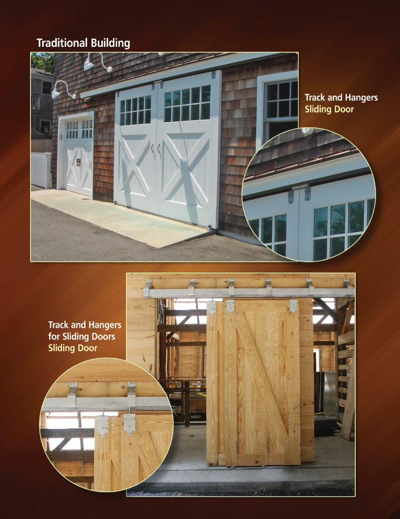
10 Hanger Designs• Sidewall Mounting• Overhead Mounting
12 Truck/Hanger Designs• Ball, Caged Roller and Polymer Bearing• Adjustable Aprons for differing door thicknesses
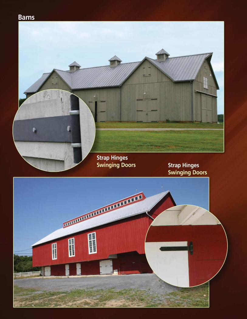
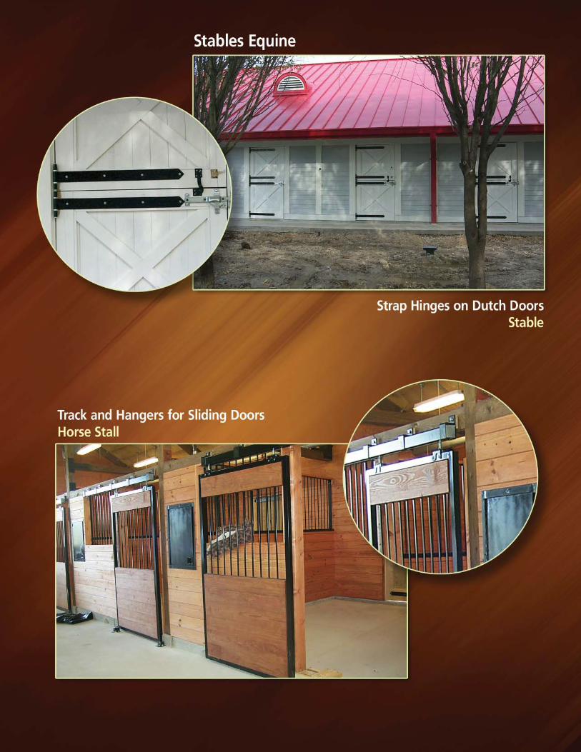
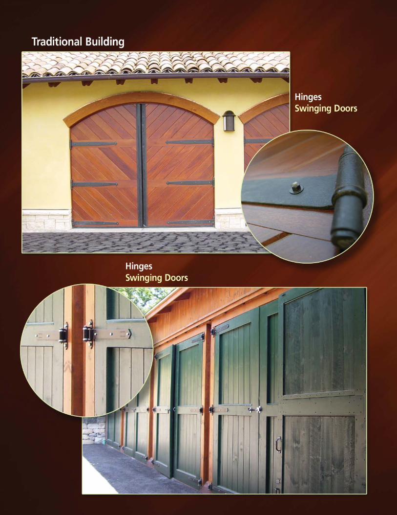
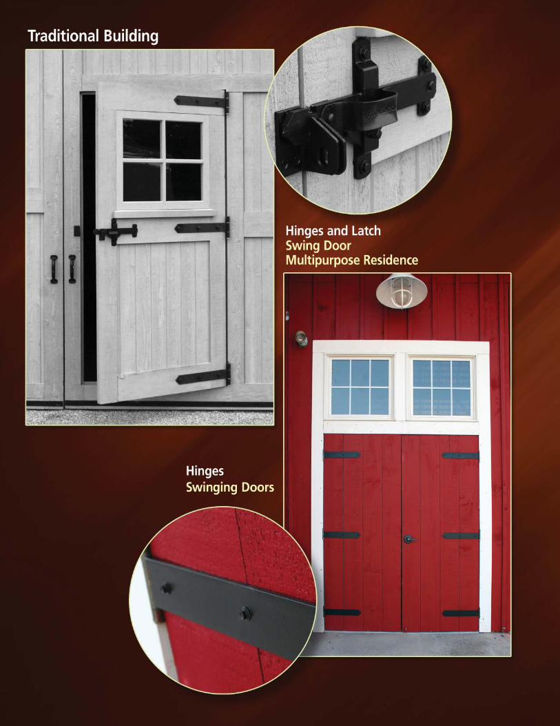
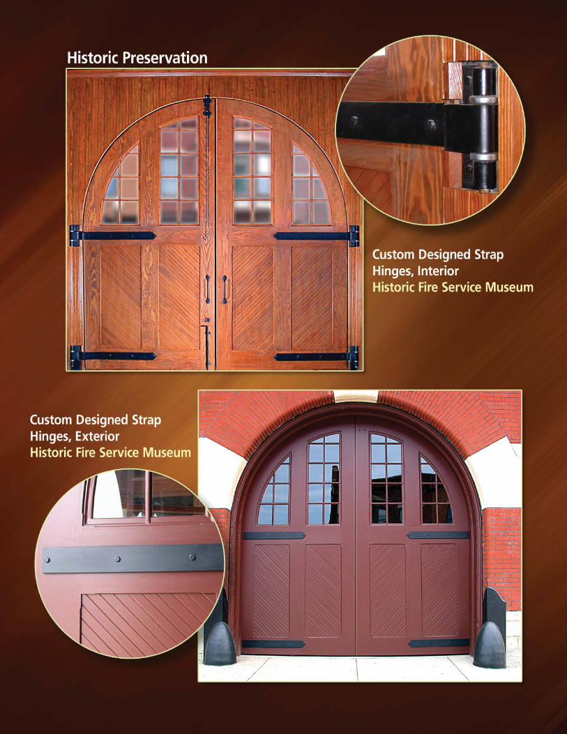
Industrial Strap Hinges• Two Designs--standard and heavy duty• Ball and Disc Bearings for different loading needs• Up to 1/2” thick material• Standard strap lengths up to 36”—longer lengths available• Decorative designs and finishes available• Complete offering with accessories
Accessories and Related Items—all with various designs and finishesLatchesStay RollersDoor StopsBow HandlesFlush Pulls
OUR ENVIRONMENTAL PLEDGE
Richards-Wilcox, Inc. is committed to the long-term preservation of our environment. For over a decade, the company has actively pursued a policy of environmental sustainability. Long before the formation of the US Green Building and LEED movement, Richards-Wilcox developed programs in manufacturing operations and its general facilities to protect the environment.
Steel used in the manufacturing of Richards-Wilcox track contains 40% recycled content from post-consumer and post-industrial sources; the track is also recyclable. Track and other hardware products are finished with a polyester powder coat that is 100% non-emissive and contains no formaldehyde, methanol, or other solvents harmful to the environment.
RICHARDS-WILCOX HARDWARE ADVANTAGES
Cremone, Cane, and Spring BoltsFire Door Fusible LinksHandrail BracketsIndustrial Curtain HangersWeather Stripping and Sweep Sets
(800) 253-5668www.rwhardware.com
II
Pre-Engineered and Packaged Hardware Sets All items are included—track, hangers, handles,
floor guides, door bolts, drawings, etc.Simple part number orderingSingle and Bi-Parting Door SetsSlide and Slide-Fold Door SetsNote: In most cases fasteners are not included with Richards-Wilcox hardware due to varying construction criteria.Strong Regional Stocking Distributor Network Extensive ExperienceFactory TrainedSame Day Shipments with In-house InventoriesService Oriented
PROVEN APPLICATIONS SINCE 1880
Doors Industrial Applications Stainless Steel ApplicationsLarge Warehouse Doors Rolling Mill Access Doors MarineVehicle Maintenance Shop Doors Industrial Oven Doors Pulp MillWoven Wire Doors Solvent Tool and Parts Cleaning Tanks ChemicalTool Crib Doors Paint Booth Access Doors PharmaceuticalAirplane Hanger Doors Welding Curtains Food ProcessingCooler Doors Portable Tool Carriers Plating/FinishingSliding Strip Doors Around-the-Corner DoorsLead and Bulletproof Doors Freezer DoorsClassroom Doors
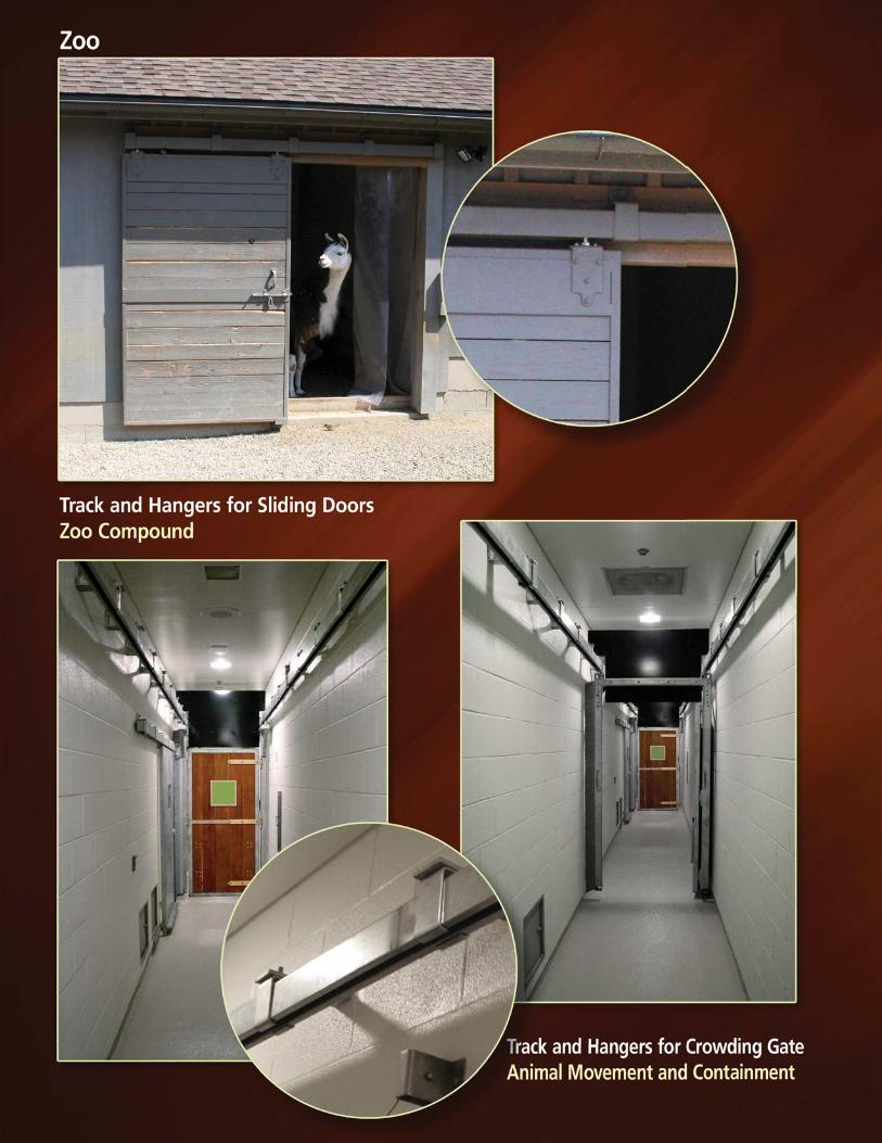
Animal Control Display PanelsZoo Doors and Gates Art GalleriesAnimal Holding Areas MuseumsCrowding Doors and Gates Chalkboards and TackboardsBarn Doors and Stalls ShowroomsMetal and Pole Building Doors BoardroomsRemote Door Actuators
Trucks SecurityDisplay Truck Doors Prison Gates and DoorsTrailer Doors SallyportsCargo Restraining Curtains Commercial Swing or Slide gates
Theater Staging MiscellaneousAcoustical Panels Sliding Room DividersStage Reducing Panels Operable WallsStage Curtains Athletic DressingStage Light Rigging Equipment Drying Weapon Target Carriers
RICHARDS-WILCOX HARDWARE ADVANTAGES
1
(800) 253-5668www.rwhardware.com
ALPHABETICAL INDEX
A
Astragal Weatherstrip ....................... 51
B
Back Plate - Decorative Hinge ......... 60Back Plate-Strap Hinge ..................... 63Binder, Steel ........................................ 38Bolts, Cane ......................................42-43Bolts, Cremone ...............................43-46Bolts, Spring ........................................ 42Bow Handles........................................ 35Brackets, Handrail .............................. 52Bumper Shoes ..................................... 38
C
Cane Bolts .......................................42-43Cane Bolts Lock Package .................. 43Concealed Floor Guide ....................... 37Cremone Bolts ................................43-46Curves, 2035 Series Track ................. 15
D
Door Holder ......................................... 39Door Guides ......................................... 39Door Latches...................................40-41Door Pulls ............................................. 34Door Stops.......................................38-39Door Top Plate ...................................... 9
E
End Stop, Door ..................................... 38
F
Flat Track/Hanger .........................31-32Floor Center Guides ........................... 39Floor Door Guides ....................36-37, 39Flush Pulls ............................................ 34Fusible Links......................................... 50
G
Guide Rollers........................................ 33Guides, Door .............................36-37, 39 Guide Roller Strip ................................ 37
H
Handle, Bow......................................... 35Handrail Brackets ............................... 52Hasps .................................................... 35Hinge Selection Guide...................53-56Hinges ..............................................55-63Hinges, Decorative ........................59-60Holder, Door ......................................... 39
K
Keepers, Spring Bolt........................... 42
L
Latches ............................................40-41Links, Fusible........................................ 50Lock Joint® Brackets ............................ 3Lock Joint® Track .................................. 4Lock Joint® Hanger ............................... 5
N
Neoprene Weatherstrip ..................... 51
O
Overhead Brackets-31 Series ............. 8Overhead Brackets-232 Series ......... 11Overhead Brackets-2035 Series ....... 14Overhead Brackets-330 Series ......... 17Overhead Brackets-376 Series ......... 20Overhead Brackets-888 Series ......... 23
P
Pulls, Flush ........................................... 34Padlock Staple .................................... 40
R
Remote Door Actuator ...................... 28Remote Crank Actuator ..................... 30
S
Shift Door Pull ...................................... 29Sidewall Brackets-31 Series ............... 8Sidewall Brackets-232 Series ........... 11Sidewall Brackets-2035 Series ......... 14Sidewall Brackets-330 Series ........... 17Sidewall Brackets-376 Series ........... 20Sidewall Brackets-888 Series ........... 23
S
Slide Fold Hardware Sets ................. 49Single/Bi-parting Hardware Sets .............................47-48 Specialty Zoo Hardware ..............28-30Spring Bolts ......................................... 42Stainless Steel Track-31 Series........ 26Stainless Steel Track-232 Series...... 26Stainless Steel Hardware .............26-27Steel Binder ......................................... 38Strap Hinge Back Plate ...................... 63Strap Hinge Selection Guide ........53-63Strap Hinges, Decorative .................. 59Strap Hinges, Industrial ..........57, 61-63Strap Hinges, Standard .....55, 57-58, 63Sweep Weatherstrip ......................... 51
T
Top Plate................................................. 9Track Curves-2035 Series .................. 15Track Section-Flat 102 Series ........... 32Track Section-Flat 105 Series ........... 31Track Section-31 Series....................... 7Track Section-232 Series................... 10Track Section-2035 Series................. 13Track Section-330 Series................... 16Track Section-376 Series................... 19Track Section-888 Series................... 22Truck/Hanger-31 Series ....................... 9Truck/Hanger-232 Series ................... 12Truck/Hanger-2035 Series ................. 13Truck/Hanger-330 Series ................... 18Truck/Hanger-376 Series ................... 21Truck/Hanger-888 Series ..............24-25
W
Warranty............................................... 64Weatherstrip ........................................ 51Weld/Jig Kit 2035 Track ..................... 14Weld/Lube Kit 888 Track .................... 22
Z
Zoo & Veterinary Hardware .........28-30
(800) 253-5668www.rwhardware.com
2
Model Number. ..............Name .................................................................Page 31 ..............Track ....................................................................... 7 31 ..............Brackets ................................................................. 8 31 ..............Truck/Hanger ......................................................... 9 31 ..............Stainless Track .................................................... 26 31 ..............Stainless Truck/Hanger .................................... 26 31 ..............Stainless Brackets ............................................. 27 54 ..............Guide Roller .......................................................... 33 58 ..............Guide Roller .......................................................... 33 58 ..............Stainless Stay Roller .......................................... 26 59 ..............Guide Roller .......................................................... 33 70 ..............Flush Pull .............................................................. 34 71 ..............Bow Handle .......................................................... 35 72 ..............Stainless Flush Pull ............................................ 26 81 ..............Bow Handle .......................................................... 35 82 ..............Binder .................................................................... 38 82 ..............Stainless Binder ................................................. 26 83 ..............Stainless Bow Handle ....................................... 26 89 ..............Binder Stop .......................................................... 38 97 ..............Fusible Link ........................................................... 50 102 ..............Bumper Shoe ....................................................... 38 102 ..............Binder .................................................................... 38 102 ..............Flat Track/Hanger ............................................... 32 105 ..............Flat Track .............................................................. 31 105 ..............Concealed Floor Guide ....................................... 37 119 ..............Door Holder .......................................................... 39 125 ..............Latch ...................................................................... 40 128 ..............Padlock Staple..................................................... 40 152 ..............Latch ...................................................................... 41 153 ..............Guide Roller ......................................................... 33 154 ..............Guide Roller ......................................................... 33 171 ..............Floor Stop ............................................................. 39 182 ..............Hasp ...................................................................... 35 191 ..............Bow Handle .......................................................... 35 216 ..............Astragal Weatherstrip........................................ 51 216 ..............Sweep Weatherstrip .......................................... 51 225 ..............Latch ..................................................................... 41 232 ..............Track ..................................................................... 10 232 ..............Brackets ............................................................... 11 232 ..............Truck/Hanger ....................................................... 12 232 ..............Stainless Brackets ............................................. 27 232 ..............Stainless Track ................................................... 26 232 ..............Stainless Truck/Hanger .................................... 26 234 ..............Zoo & Veterinary Hardware ....................... 28-30 330 ..............Track ..................................................................... 16 330 ..............Brackets ............................................................... 17 330 ..............Truck/Hanger ....................................................... 18 376 ..............Track ..................................................................... 19 376 ..............Bracket ................................................................. 20
Model Number ..............Name .................................................................Page 376 ..............Truck/Hanger ....................................................... 21 434 ..............Hardware Sets..................................................... 49 434 ..............Hinges ............................................................. 61-63 434 ..............Hinge Back Plate................................................. 63 434 ..............Spring Bolts .......................................................... 42 434 ..............Keeper ................................................................... 42 470 ..............Flush Pull .............................................................. 34 514 ..............Spring Bolts .......................................................... 42 524 ..............Cane Bolt .............................................................. 42 535 ..............Flush Pull .............................................................. 34 566 ..............Handrail Bracket ................................................. 52 572 ..............End Stop ................................................................ 38 647 ..............Guide Roller Strip ................................................ 37 739 ..............Floor Guide ........................................................... 36 739 ..............Floor Guide Track ................................................ 36 771 ..............Door Guide ........................................................... 39 888 ..............Track ..................................................................... 22 888 ..............Weld/Lube Kit ...................................................... 22 888 ..............Bracket ................................................................. 23 888 ..............Truck/Hanger ................................................. 24-25 1025 ..............Latch ...................................................................... 41 1028 ..............Heavy-duty Cremone Bolt............................ 43-44 1028 ..............Extra Heavy-duty Cremone Bolt ................. 45-46 1035 ..............Hardware Sets..................................................... 49 1035 ..............Hinge Back Plate................................................. 63 1035 ..............Strap Hinges ........................................................ 57 1035 ..............Decorative Strap Hinges.................................... 59 1035 ..............Decorative Strap Hinge Back Plate ................. 60 1036 ..............Hinge Back Plate................................................. 63 1036 ..............Strap Hinges ........................................................ 57 1036 ..............Decorative Strap Hinges.................................... 59 1036 ..............Decorative Hinge Back Plate ............................ 60 1040 ..............Strap Hinges ........................................................ 58 1047 ..............Strap Hinges ........................................................ 58 1600 ..............Hardware Sets............................................... 47-48 2035 ..............Track ..................................................................... 13 2035 ..............Truck/Hanger ....................................................... 13 2035 ..............Brackets ............................................................... 14 2035 ..............Welding Jig .......................................................... 14 2035 ..............Curved Track ........................................................ 15 2600 ..............Hardware Sets............................................... 47-48 3110 ..............Top Plate ................................................................. 9 3110 ..............Truck/Hanger ......................................................... 9 3120 ..............Truck/Hanger ......................................................... 9 3130 ..............Utility Hanger ......................................................... 7 3140 ..............Utility Hanger ......................................................... 7
NUMERICAL INDEX
3
(800) 253-5668www.rwhardware.com
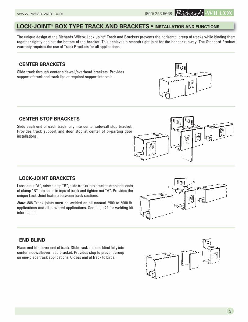
The unique design of the Richards-Wilcox Lock-Joint® Track and Brackets prevents the horizontal creep of tracks while binding them together tightly against the bottom of the bracket. This achieves a smooth tight joint for the hanger runway. The Standard Product warranty requires the use of Track Brackets for all applications.
CENTER BRACKETS
Slide track through center sidewall/overhead brackets. Provides support of track and track lips at required support intervals.
CENTER STOP BRACKETS
Slide each end of each track fully into center sidewall stop bracket. Provides track support and door stop at center of bi-parting door installations.
LOCK-JOINT BRACKETS
Loosen nut “A”, raise clamp “B”, slide tracks into bracket, drop bent ends of clamp “B” into holes in tops of track and tighten nut “A”. Provides the unique Lock-Joint feature between track sections.
Note: 888 Track joints must be welded on all manual 2500 to 5000 lb. applications and all powered applications. See page 22 for welding kit information.
END BLIND
Place end blind over end of track. Slide track and end blind fully into center sidewall/overhead bracket. Provides stop to prevent creep on one-piece track applications. Closes end of track to birds.
LOCK-JOINT® BOX TYPE TRACK AND BRACKETS • INSTALLATION AND FUNCTIONS
(800) 253-5668www.rwhardware.com
4
Capacity1
for DoorsWeighing__Pounds
TrackNumber Gauge
InsideDimensions
in Inches
AvailableLengths
Feet
StandardFinish/
PowderCoat
GalvanizedSteel
Available
Hot-dippedGalvanizedAvailable
StainlessSteel
Available
PoundPerFoot
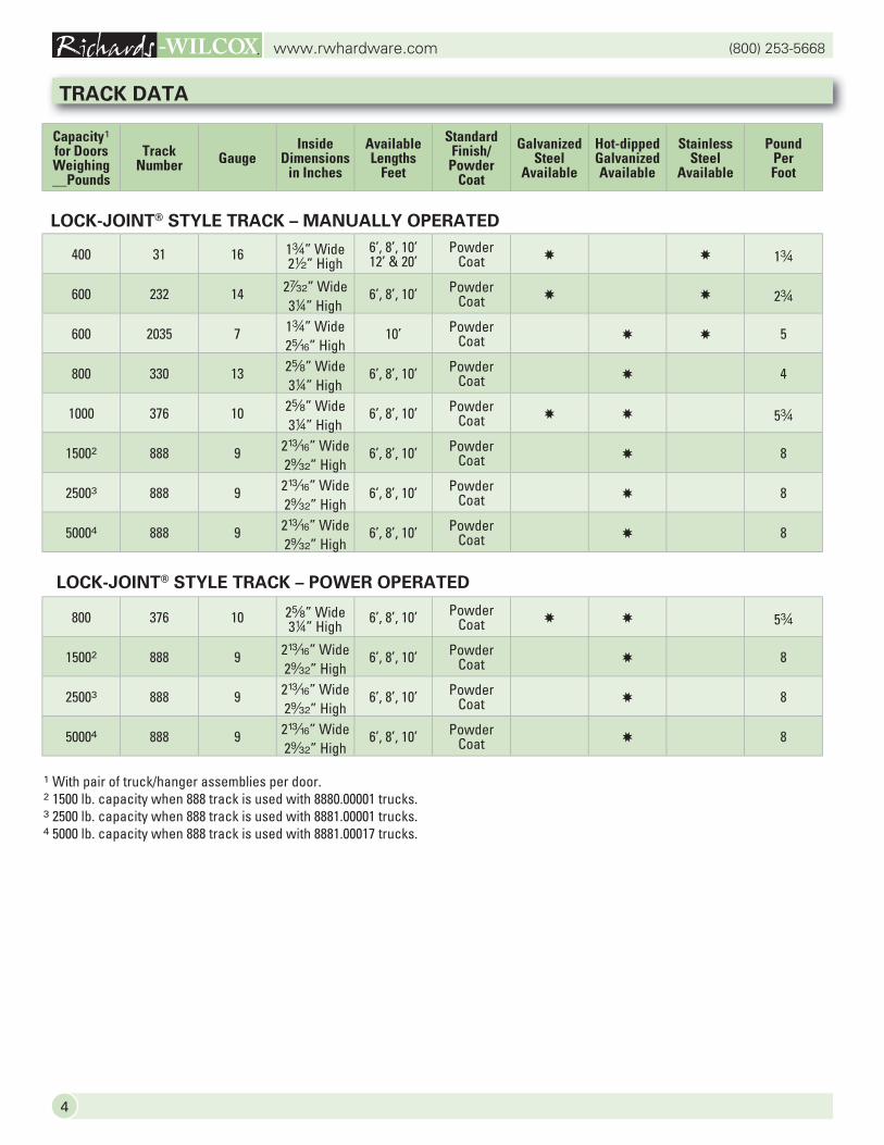
LOCK-JOINT® STYLE TRACK – MANUALLY OPERATED
1 With pair of truck/hanger assemblies per door.2 1500 lb. capacity when 888 track is used with 8880.00001 trucks.3 2500 lb. capacity when 888 track is used with 8881.00001 trucks.4 5000 lb. capacity when 888 track is used with 8881.00017 trucks.
TRACK DATA
LOCK-JOINT® STYLE TRACK – POWER OPERATED
800 376 10 2s” Wide34” High
6’, 8’, 10’ Powder Coat ✸ ✸ 5w
15002 888 9 2m” Wide2¥” High
6’, 8’, 10’ Powder Coat ✸ 8
25003 888 9 2m” Wide2¥” High
6’, 8’, 10’ Powder Coat ✸ 8
50004 888 9 2m” Wide2¥” High
6’, 8’, 10’ Powder Coat ✸ 8
400 31 16 1w” Wide 22” High
6’, 8’, 10’12’ & 20’
Powder Coat ✸ ✸ 1w
600 232 14 2†” Wide34” High
6’, 8’, 10’ Powder Coat ✸ ✸ 2w
600 2035 7 1w” Wide2c” High
10’ Powder Coat ✸ ✸ 5
800 330 13 2s” Wide34” High
6’, 8’, 10’ Powder Coat ✸ 4
1000 376 10 2s” Wide34” High
6’, 8’, 10’ Powder Coat ✸ ✸ 5w
15002 888 9 2m” Wide2¥” High
6’, 8’, 10’ Powder Coat ✸ 8
25003 888 9 2m” Wide2¥” High
6’, 8’, 10’ Powder Coat ✸ 8
50004 888 9 2m” Wide2¥” High
6’, 8’, 10’ Powder Coat ✸ 8
5
(800) 253-5668www.rwhardware.com
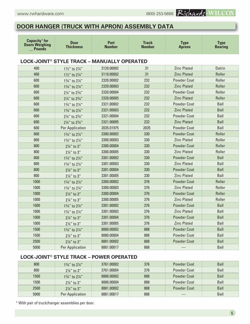
800 1w” to 24” 3761.00002 376 Powder Coat Ball800 24” to 3” 3761.00004 376 Powder Coat Ball1500 1w” to 24” 8880.00002 888 Powder Coat Ball1500 24” to 3” 8880.00004 888 Powder Coat Ball2500 24” to 3” 8881.00002 888 Powder Coat Ball5000 Per Application 8881.00017 888 — Ball
LOCK-JOINT® STYLE TRACK – POWER OPERATED
1 With pair of truck/hanger assemblies per door.
Capacity1 forDoors Weighing
__ PoundsDoor
ThicknessPart
NumberTrack
NumberType
ApronsType
Bearing
400 12” to 24” 3120.00002 31 Zinc Plated Delrin400 12” to 24” 3110.00002 31 Zinc Plated Roller600 1w” to 24” 2320.00002 232 Powder Coat Roller600 1w” to 24” 2320.00003 232 Zinc Plated Roller600 24” to 2w” 2320.00004 232 Powder Coat Roller600 24” to 2w” 2320.00005 232 Zinc Plated Roller600 1w” to 24” 2321.00002 232 Powder Coat Ball600 1w” to 24” 2321.00003 232 Zinc Plated Ball600 24” to 2w” 2321.00004 232 Powder Coat Ball600 24” to 2w” 2321.00005 232 Zinc Plated Ball600 Per Application 2035.01975 2035 Powder Coat Ball800 1w” to 24” 3300.00002 330 Powder Coat Roller800 1w” to 24” 3300.00003 330 Zinc Plated Roller800 24” to 3” 3300.00004 330 Powder Coat Roller800 24” to 3” 3300.00005 330 Zinc Plated Roller800 1w” to 24” 3301.00002 330 Powder Coat Ball800 1w” to 24” 3301.00003 330 Zinc Plated Ball800 24” to 3” 3301.00004 330 Powder Coat Ball800 24” to 3” 3301.00005 330 Zinc Plated Ball
1000 1w” to 24” 3300.00002 376 Powder Coat Roller1000 1w” to 24” 3300.00003 376 Zinc Plated Roller1000 24” to 3” 3300.00004 376 Powder Coat Roller1000 24” to 3” 3300.00005 376 Zinc Plated Roller1000 1w” to 24” 3301.00002 376 Powder Coat Ball1000 1w” to 24” 3301.00003 376 Zinc Plated Ball1000 24” to 3” 3301.00004 376 Powder Coat Ball1000 24” to 3” 3301.00005 376 Zinc Plated Ball1500 1w” to 24” 8880.00002 888 Powder Coat Ball1500 24” to 3” 8880.00004 888 Powder Coat Ball2500 24” to 3” 8881.00002 888 Powder Coat Ball5000 Per Application 8881.00017 888 — Ball
DOOR HANGER (TRUCK WITH APRON) ASSEMBLY DATA
LOCK-JOINT® STYLE TRACK – MANUALLY OPERATED
(800) 253-5668www.rwhardware.com
6
31 Track 400#6 Foot Section8 Foot Section
10 Foot Section12 Foot Section20 Foot Section
4567
11
22222
11111
4567
11
44444
11111
232 Track 600#6 Foot Section8 Foot Section
10 Foot Section
456
222
111
456
444
111
2035 Track 600#10 Foot Section 3 **
330 Track 800#6 Foot Section8 Foot Section
10 Foot Section
456
222
111
456
444
111
376 Track 1000#6 Foot Section8 Foot Section
10 Foot Section
456
222
111
444
444
111
888 Track 2500#6 Foot Section8 Foot Section
10 Foot Section
333
222
111
888 Track 5000#6 Foot Section8 Foot Section
10 Foot Section
456
222
*********
31 Track 400#6 Foot Section8 Foot Section
10 Foot Section12 Foot Section20 Foot Section
4567
11
22222
11111
4567
11
22222
11111
232 Track 600#6 Foot Section8 Foot Section
10 Foot Section
456
222
111
456
222
111
2035 Track 600#
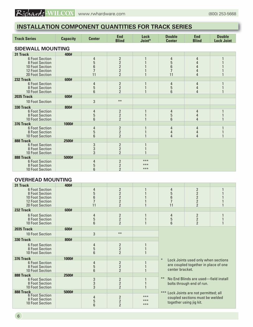
* Lock Joints used only when sections are coupled together in place of one center bracket.
** No End Blinds are used—field install bolts through end of run.
*** Lock Joints are not permitted; all coupled sections must be welded together using jig kit.
10 Foot Section 3 **330 Track 800#
6 Foot Section8 Foot Section
10 Foot Section
456
222
111
376 Track 1000#6 Foot Section8 Foot Section
10 Foot Section
456
222
111
888 Track 2500#6 Foot Section8 Foot Section
10 Foot Section
333
222
111
888 Track 5000#6 Foot Section8 Foot Section
10 Foot Section456
222
*********
INSTALLATION COMPONENT QUANTITIES FOR TRACK SERIES
Track Series Capacity Center End Blind
Lock Joint*
Double Center
End Blind
Double Lock Joint
SIDEWALL MOUNTING
OVERHEAD MOUNTING
7
(800) 253-5668www.rwhardware.com
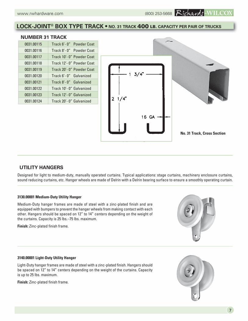
UTILITY HANGERS
Designed for light to medium-duty, manually operated curtains. Typical applications: stage curtains, machinery enclosure curtains, sound reducing curtains, etc. Hanger wheels are made of Delrin with a Delrin bearing surface to ensure a smoothly operating curtain.
3130.00001 Medium-Duty Utility Hanger
Medium-Duty hanger frames are made of steel with a zinc-plated finish and are equipped with bumpers to prevent the hanger wheels from making contact with each other. Hangers should be spaced on 12” to 14” centers depending on the weight of the curtains. Capacity is 25 lbs.–75 lbs. maximum.
Finish: Zinc-plated finish frame.
3140.00001 Light-Duty Utility Hanger
Light-Duty hanger frames are made of steel with a zinc-plated finish. Hangers should be spaced on 12” to 14” centers depending on the weight of the curtains. Capacity is up to 25 lbs. maximum.
Finish: Zinc-plated finish frame.
LOCK-JOINT® BOX TYPE TRACK • NO. 31 TRACK 400 LB. CAPACITY PER PAIR OF TRUCKS
NUMBER 31 TRACK
No. 31 Track, Cross Section
0031.00115 Track 6’- 0” Powder Coat
0031.00116 Track 8’- 0” Powder Coat
0031.00117 Track 10’- 0” Powder Coat
0031.00118 Track 12’- 0” Powder Coat
0031.00119 Track 20’- 0” Powder Coat
0031.00120 Track 6’- 0” Galvanized
0031.00121 Track 8’- 0” Galvanized
0031.00122 Track 10’- 0” Galvanized
0031.00123 Track 12’- 0” Galvanized
0031.00124 Track 20’- 0” Galvanized
(800) 253-5668www.rwhardware.com
8
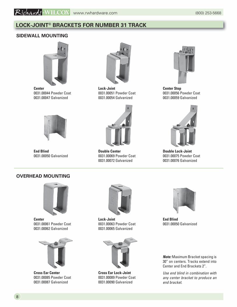
OVERHEAD MOUNTING
Note: Maximum Bracket spacing is 30” on centers. Tracks extend into Center and End Brackets 2”.
Use end blind in combination with any center bracket to produce an end bracket.
Center0031.00044 Powder Coat0031.00047 Galvanized
Lock-Joint0031.00051 Powder Coat0031.00054 Galvanized
Center Stop0031.00056 Powder Coat0031.00059 Galvanized
End Blind0031.00050 Galvanized
Double Center0031.00069 Powder Coat0031.00072 Galvanized
Double Lock-Joint0031.00075 Powder Coat0031.00076 Galvanized
Cross Ear Center0031.00085 Powder Coat0031.00087 Galvanized
Cross Ear Lock-Joint0031.00089 Powder Coat0031.00090 Galvanized
SIDEWALL MOUNTING
LOCK-JOINT® BRACKETS FOR NUMBER 31 TRACK
Center0031.00061 Powder Coat0031.00062 Galvanized
Lock-Joint0031.00063 Powder Coat0031.00065 Galvanized
End Blind0031.00050 Galvanized
9
(800) 253-5668www.rwhardware.com
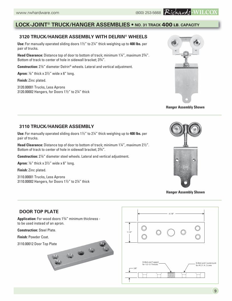
LOCK-JOINT® TRUCK/HANGER ASSEMBLIES • NO. 31 TRACK 400 LB. CAPACITY
3120 TRUCK/HANGER ASSEMBLY WITH DELRIN® WHEELS
Use: For manually operated sliding doors 12” to 24” thick weighing up to 400 lbs. per pair of trucks.
Head Clearance: Distance top of door to bottom of track; minimum 14”, maximum 2w”.Bottom of track to center of hole in sidewall bracket; 3w”.
Construction: 28” diameter Delrin® wheels. Lateral and vertical adjustment.
Apron: 8” thick x 32” wide x 6” long.
Finish: Zinc plated.
3120.00001 Trucks, Less Aprons3120.00002 Hangers, for Doors 12” to 24” thick
3110 TRUCK/HANGER ASSEMBLY
Use: For manually operated sliding doors 12” to 24” thick weighing up to 400 lbs. per pair of trucks.
Head Clearance: Distance top of door to bottom of track; minimum 14”, maximum 22”. Bottom of track to center of hole in sidewall bracket; 3w”.
Construction: 28” diameter steel wheels. Lateral and vertical adjustment.
Apron: 8” thick x 32” wide x 6” long.
Finish: Zinc plated.
3110.00001 Trucks, Less Aprons3110.00002 Hangers, for Doors 12” to 24” thick
DOOR TOP PLATE
Application: For wood doors 1w” minimum thickness - to be used instead of an apron.
Construction: Steel Plate.
Finish: Powder Coat.
3110.00012 Door Top Plate
Hanger Assembly Shown
Hanger Assembly Shown
Drilled and Tappedfor 1/2-13 Threads
Drilled and Countersunkfor #12 F.H. Screw
1-1/2"
4-7/8"
3/8"
(800) 253-5668www.rwhardware.com
10
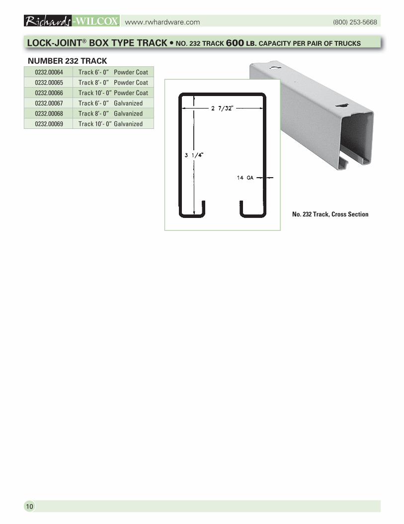
0232.00064 Track 6’- 0” Powder Coat
0232.00065 Track 8’- 0” Powder Coat
0232.00066 Track 10’- 0” Powder Coat
0232.00067 Track 6’- 0” Galvanized
0232.00068 Track 8’- 0” Galvanized
0232.00069 Track 10’- 0” Galvanized
LOCK-JOINT® BOX TYPE TRACK • NO. 232 TRACK 600 LB. CAPACITY PER PAIR OF TRUCKS
NUMBER 232 TRACK
No. 232 Track, Cross Section

11
(800) 253-5668www.rwhardware.com
LOCK-JOINT® BRACKETS FOR NUMBER 232 TRACK
OVERHEAD MOUNTING
SIDEWALL MOUNTING
Note: Maximum Bracket spacing is 24” on centers. Tracks extend into Center and End Brackets 2w”.
Use end blind in combination with any center bracket to produce an end bracket.
Center0232.00121 Powder Coat0232.00121ZC Zinc Plated
Lock-Joint0232.00122 Powder Coat0232.00122ZC Zinc Plated
Center Stop0232.00123 Powder Coat0232.00123ZC Zinc Plated
End Blind0232.00007 Galvanized
Double Center0232.00026 Powder Coat
Double Lock-Joint0232.00032 Powder Coat
Cross Ear Center0232.00044 Powder Coat0232.00046 Zinc Plated
Cross Ear Lock-Joint0232.00048 Powder Coat0232.00049 Zinc Plated
Center0232.00018 Powder Coat0232.00019 Zinc Plated
Lock-Joint0232.00020 Powder Coat0232.00022 Zinc Plated
End Blind0232.00007 Galvanized
(800) 253-5668www.rwhardware.com
12
LOCK-JOINT® TRUCK/HANGER ASSEMBLIES • NO. 232 TRACK 600 LB. CAPACITY
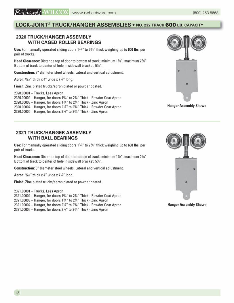
2320 TRUCK/HANGER ASSEMBLY WITH CAGED ROLLER BEARINGS
Use: For manually operated sliding doors 1w” to 2w” thick weighing up to 600 lbs. per pair of trucks.
Head Clearance: Distance top of door to bottom of track; minimum 18”, maximum 2w”. Bottom of track to center of hole in sidewall bracket; 54”.
Construction: 3” diameter steel wheels. Lateral and vertical adjustment.
Apron: 9/64” thick x 4” wide x 74” long.
Finish: Zinc plated trucks/apron plated or powder coated.
2320.00001 – Trucks, Less Apron2320.00002 – Hanger, for doors 1w” to 24” Thick - Powder Coat Apron2320.00003 – Hanger, for doors 1w” to 24” Thick - Zinc Apron2320.00004 – Hanger, for doors 24” to 2w” Thick - Powder Coat Apron2320.00005 – Hanger, for doors 24” to 2w” Thick - Zinc Apron
2321 TRUCK/HANGER ASSEMBLY
WITH BALL BEARINGS
Use: For manually operated sliding doors 1w” to 2w” thick weighing up to 600 lbs. per pair of trucks.
Head Clearance: Distance top of door to bottom of track; minimum 18”, maximum 2w”.Bottom of track to center of hole in sidewall bracket; 54”.
Construction: 3” diameter steel wheels. Lateral and vertical adjustment.
Apron: 9/64” thick x 4” wide x 74” long.
Finish: Zinc plated trucks/apron plated or powder coated.
2321.00001 – Trucks, Less Apron2321.00002 – Hanger, for doors 1w” to 24” Thick - Powder Coat Apron2321.00003 – Hanger, for doors 1w” to 24” Thick - Zinc Apron2321.00004 – Hanger, for doors 24” to 2w” Thick - Powder Coat Apron2321.00005 – Hanger, for doors 24” to 2w” Thick - Zinc Apron
Hanger Assembly Shown
Hanger Assembly Shown
13
(800) 253-5668www.rwhardware.com
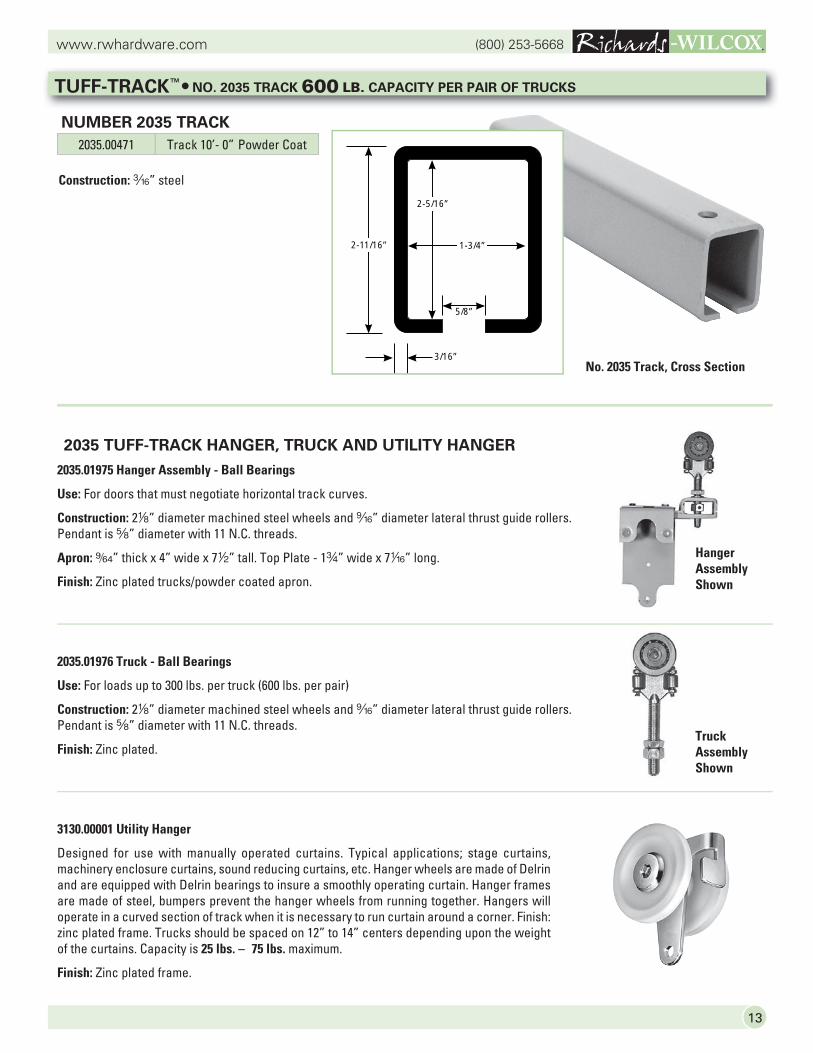
2035 TUFF-TRACK HANGER, TRUCK AND UTILITY HANGER
2035.01975 Hanger Assembly - Ball Bearings
Use: For doors that must negotiate horizontal track curves.
Construction: 28” diameter machined steel wheels and b” diameter lateral thrust guide rollers. Pendant is s” diameter with 11 N.C. threads.
Apron: 9/64” thick x 4” wide x 72” tall. Top Plate - 1w” wide x 7z” long.
Finish: Zinc plated trucks/powder coated apron.
2035.01976 Truck - Ball Bearings
Use: For loads up to 300 lbs. per truck (600 lbs. per pair)
Construction: 28” diameter machined steel wheels and b” diameter lateral thrust guide rollers. Pendant is s” diameter with 11 N.C. threads.
Finish: Zinc plated.
3130.00001 Utility Hanger
Designed for use with manually operated curtains. Typical applications; stage curtains, machinery enclosure curtains, sound reducing curtains, etc. Hanger wheels are made of Delrin and are equipped with Delrin bearings to insure a smoothly operating curtain. Hanger frames are made of steel, bumpers prevent the hanger wheels from running together. Hangers will operate in a curved section of track when it is necessary to run curtain around a corner. Finish: zinc plated frame. Trucks should be spaced on 12” to 14” centers depending upon the weight of the curtains. Capacity is 25 lbs. – 75 lbs. maximum.
Finish: Zinc plated frame.
Truck Assembly Shown
Hanger Assembly Shown
TUFF-TRACK™ • NO. 2035 TRACK 600 LB. CAPACITY PER PAIR OF TRUCKS
Construction: x” steel
NUMBER 2035 TRACK
No. 2035 Track, Cross Section
2035.00471 Track 10’- 0” Powder CoatPART 471
2-5/16”
1-3/4”
3/16”
2-11/16”
5/8”
(800) 253-5668www.rwhardware.com
14
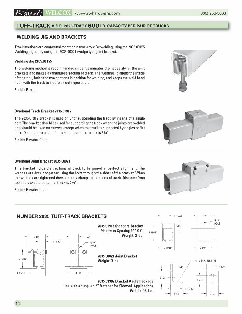
WELDING JIG AND BRACKETS
Track sections are connected together in two ways: By welding using the 2035.00155 Welding Jig, or by using the 2035.00021 wedge type joint bracket.
Welding Jig 2035.00155
The welding method is recommended since it eliminates the necessity for the joint brackets and makes a continuous section of track. The welding jig aligns the inside of the track, holds the two sections in position for welding, and keeps the weld bead flush with the track to insure smooth operation.
Finish: Brass.
Overhead Track Bracket 2035.01912
The 2035.01912 bracket is used only for suspending the track by means of a single bolt. The bracket should be used for supporting the track when the joints are welded and should be used on curves, except when the track is supported by angles or flat bars. Distance from top of bracket to bottom of track is 3w”.
Finish: Powder Coat.
Overhead Joint Bracket 2035.00021
This bracket holds the sections of track to be joined in perfect alignment. The wedges are drawn together using the bolts through the sides of the bracket. When the wedges are tightened they securely clamp the sections of track. Distance from top of bracket to bottom of track is 3w”.
Finish: Powder Coat.
NUMBER 2035 TUFF-TRACK BRACKETS
3 15/16"
2 11/16"
3/4"
2 1/2"
1 1/4"1 11/32"
9/16"HOLE
2 1/2"
2 1/2" 2 1/2"
1 11/16"
1 1/4"
1 11/16"
3/8"
9/16" DIA. HOLE (2)
2 11/16"
3 15/16"
3 1/2"
3 1/2"
1 11/32"
1 3/4"
9/16"HOLE
2035.01912 Standard BracketMaximum Spacing 60” O.C.
Weight: 2 lbs.
2035.00021 Joint BracketWeight: 3 lbs.
2035.01982 Bracket Angle PackageUse with a supplied 2” fastener for Sidewall Applications
Weight: 3 lbs.
TUFF-TRACK • NO. 2035 TRACK 600 LB. CAPACITY PER PAIR OF TRUCKS
15
(800) 253-5668www.rwhardware.com
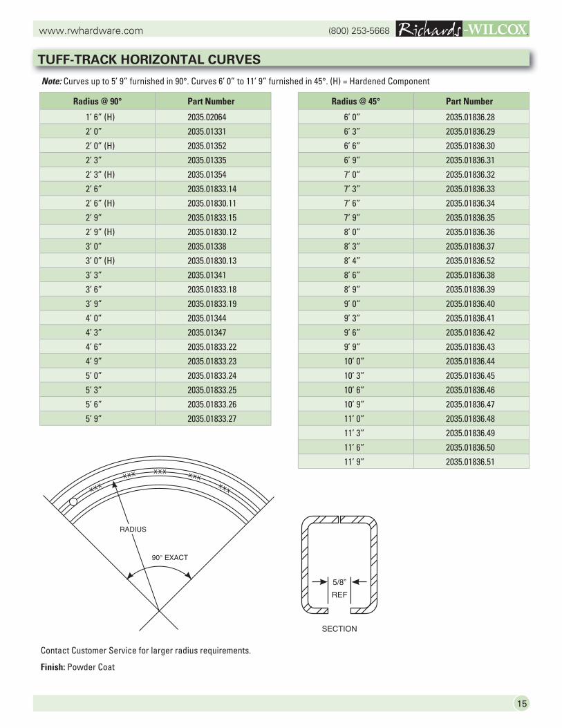
Contact Customer Service for larger radius requirements.
Finish: Powder Coat
TUFF-TRACK HORIZONTAL CURVES
Radius @ 90° Part Number
1’ 6” (H) 2035.02064
2’ 0” 2035.01331
2’ 0” (H) 2035.01352
2’ 3” 2035.01335
2’ 3” (H) 2035.01354
2’ 6” 2035.01833.14
2’ 6” (H) 2035.01830.11
2’ 9” 2035.01833.15
2’ 9” (H) 2035.01830.12
3’ 0” 2035.01338
3’ 0” (H) 2035.01830.13
3’ 3” 2035.01341
3’ 6” 2035.01833.18
3’ 9” 2035.01833.19
4’ 0” 2035.01344
4’ 3” 2035.01347
4’ 6” 2035.01833.22
4’ 9” 2035.01833.23
5’ 0” 2035.01833.24
5’ 3” 2035.01833.25
5’ 6” 2035.01833.26
5’ 9” 2035.01833.27
Radius @ 45° Part Number
6’ 0” 2035.01836.28
6’ 3” 2035.01836.29
6’ 6” 2035.01836.30
6’ 9” 2035.01836.31
7’ 0” 2035.01836.32
7’ 3” 2035.01836.33
7’ 6” 2035.01836.34
7’ 9” 2035.01836.35
8’ 0” 2035.01836.36
8’ 3” 2035.01836.37
8’ 4” 2035.01836.52
8’ 6” 2035.01836.38
8’ 9” 2035.01836.39
9’ 0” 2035.01836.40
9’ 3” 2035.01836.41
9’ 6” 2035.01836.42
9’ 9” 2035.01836.43
10’ 0” 2035.01836.44
10’ 3” 2035.01836.45
10’ 6” 2035.01836.46
10’ 9” 2035.01836.47
11’ 0” 2035.01836.48
11’ 3” 2035.01836.49
11’ 6” 2035.01836.50
11’ 9” 2035.01836.51
Note: Curves up to 5’ 9” furnished in 90°. Curves 6’ 0” to 11’ 9” furnished in 45°. (H) = Hardened Component
(800) 253-5668www.rwhardware.com
16
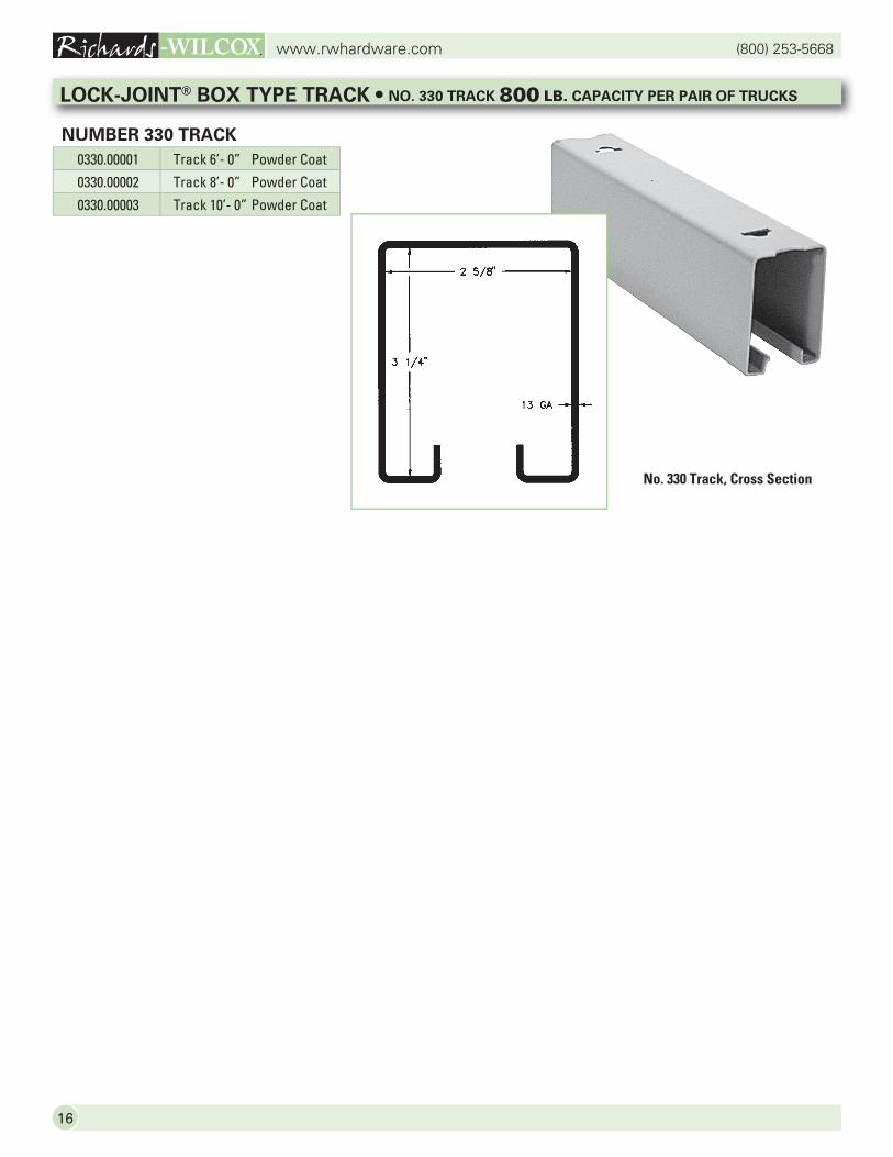
0330.00001 Track 6’- 0” Powder Coat
0330.00002 Track 8’- 0” Powder Coat
0330.00003 Track 10’- 0” Powder Coat
LOCK-JOINT® BOX TYPE TRACK • NO. 330 TRACK 800 LB. CAPACITY PER PAIR OF TRUCKS
NUMBER 330 TRACK
No. 330 Track, Cross Section
17
(800) 253-5668www.rwhardware.com
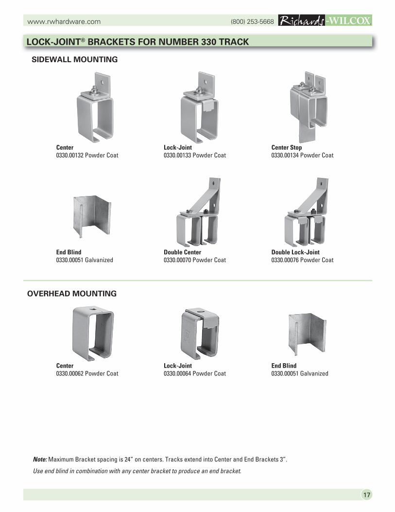
LOCK-JOINT® BRACKETS FOR NUMBER 330 TRACK
OVERHEAD MOUNTING
SIDEWALL MOUNTING
Note: Maximum Bracket spacing is 24” on centers. Tracks extend into Center and End Brackets 3”.
Use end blind in combination with any center bracket to produce an end bracket.
Center0330.00132 Powder Coat
Lock-Joint0330.00133 Powder Coat
Center Stop0330.00134 Powder Coat
End Blind0330.00051 Galvanized
Double Center0330.00070 Powder Coat
Double Lock-Joint0330.00076 Powder Coat
Center0330.00062 Powder Coat
Lock-Joint0330.00064 Powder Coat
End Blind0330.00051 Galvanized
(800) 253-5668www.rwhardware.com
18
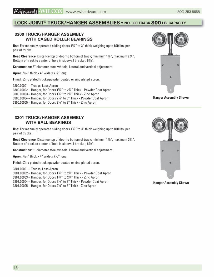
3300 TRUCK/HANGER ASSEMBLY
WITH CAGED ROLLER BEARINGS
Use: For manually operated sliding doors 1w” to 3” thick weighing up to 800 lbs. per pair of trucks.
Head Clearance: Distance top of door to bottom of track; minimum 18”, maximum 2w”.Bottom of track to center of hole in sidewall bracket; 6a”.
Construction: 3” diameter steel wheels. Lateral and vertical adjustment.
Apron: 9/64” thick x 4” wide x 72” long.
Finish: Zinc plated trucks/powder coated or zinc plated apron.
3300.00001 – Trucks, Less Apron3300.00002 – Hanger, for Doors 1w” to 24” Thick - Powder Coat Apron3300.00003 – Hanger, for Doors 1w” to 24” Thick - Zinc Apron3300.00004 – Hanger, for Doors 24” to 3” Thick - Powder Coat Apron3300.00005 – Hanger, for Doors 24” to 3” Thick - Zinc Apron
3301 TRUCK/HANGER ASSEMBLY
WITH BALL BEARINGS
Use: For manually operated sliding doors 1w” to 3” thick weighing up to 800 lbs. per pair of trucks.
Head Clearance: Distance top of door to bottom of track; minimum 18”, maximum 2w”.Bottom of track to center of hole in sidewall bracket; 6a”.
Construction: 3” diameter steel wheels. Lateral and vertical adjustment.
Apron: 9/64” thick x 4” wide x 72” long.
Finish: Zinc plated trucks/powder coated or zinc plated apron.
3301.00001 – Trucks, Less Apron3301.00002 – Hanger, for Doors 1w” to 24” Thick - Powder Coat Apron3301.00003 – Hanger, for Doors 1w” to 24” Thick - Zinc Apron3301.00004 – Hanger, for Doors 24” to 3” Thick - Powder Coat Apron3301.00005 – Hanger, for Doors 24” to 3” Thick - Zinc Apron
LOCK-JOINT® TRUCK/HANGER ASSEMBLIES • NO. 330 TRACK 800 LB. CAPACITY
Hanger Assembly Shown
Hanger Assembly Shown
19
(800) 253-5668www.rwhardware.com
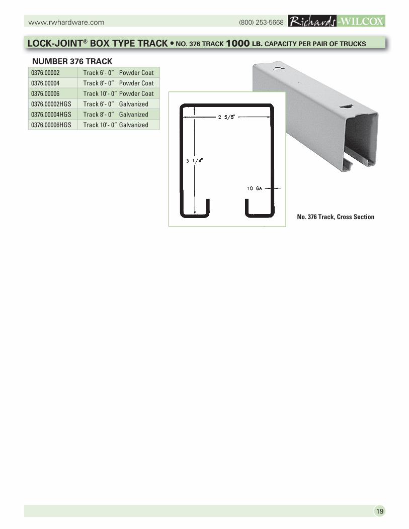
LOCK-JOINT® BOX TYPE TRACK • NO. 376 TRACK 1000 LB. CAPACITY PER PAIR OF TRUCKS
NUMBER 376 TRACK
No. 376 Track, Cross Section
0376.00002 Track 6’- 0” Powder Coat
0376.00004 Track 8’- 0” Powder Coat
0376.00006 Track 10’- 0” Powder Coat
0376.00002HGS Track 6’- 0” Galvanized
0376.00004HGS Track 8’- 0” Galvanized
0376.00006HGS Track 10’- 0” Galvanized
(800) 253-5668www.rwhardware.com
20
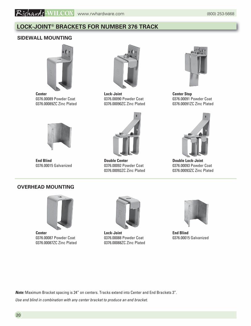
LOCK-JOINT® BRACKETS FOR NUMBER 376 TRACK
OVERHEAD MOUNTING
SIDEWALL MOUNTING
Note: Maximum Bracket spacing is 24” on centers. Tracks extend into Center and End Brackets 3”.
Use end blind in combination with any center bracket to produce an end bracket.
Center0376.00089 Powder Coat0376.00089ZC Zinc Plated
Lock-Joint0376.00090 Powder Coat0376.00090ZC Zinc Plated
Center Stop0376.00091 Powder Coat0376.00091ZC Zinc Plated
End Blind0376.00015 Galvanized
Double Center0376.00092 Powder Coat0376.00092ZC Zinc Plated
Double Lock-Joint0376.00093 Powder Coat0376.00093ZC Zinc Plated
Center0376.00087 Powder Coat0376.00087ZC Zinc Plated
Lock-Joint0376.00088 Powder Coat0376.00088ZC Zinc Plated
End Blind0376.00015 Galvanized
21
(800) 253-5668www.rwhardware.com
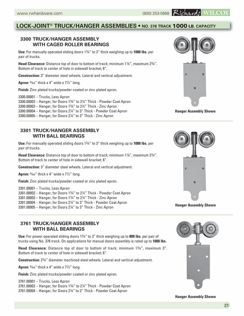
3300 TRUCK/HANGER ASSEMBLY
WITH CAGED ROLLER BEARINGS
Use: For manually operated sliding doors 1w” to 3” thick weighing up to 1000 lbs. per pair of trucks.
Head Clearance: Distance top of door to bottom of track; minimum 18”, maximum 2w”.Bottom of track to center of hole in sidewall bracket; 6”.
Construction: 3” diameter steel wheels. Lateral and vertical adjustment.
Apron: 9/64” thick x 4” wide x 72” long.
Finish: Zinc plated trucks/powder coated or zinc plated apron.
3300.00001 – Trucks, Less Apron3300.00002 – Hanger, for Doors 1w” to 24” Thick - Powder Coat Apron3300.00003 – Hanger, for Doors 1w” to 24” Thick - Zinc Apron3300.00004 – Hanger, for Doors 24” to 3” Thick - Powder Coat Apron3300.00005 – Hanger, for Doors 24” to 3” Thick - Zinc Apron
3301 TRUCK/HANGER ASSEMBLY
WITH BALL BEARINGS
Use: For manually operated sliding doors 1w” to 3” thick weighing up to 1000 lbs. per pair of trucks.
Head Clearance: Distance top of door to bottom of track; minimum 18”, maximum 2w”.Bottom of track to center of hole in sidewall bracket; 6”.
Construction: 3” diameter steel wheels. Lateral and vertical adjustment.
Apron: 9/64” thick x 4” wide x 72” long.
Finish: Zinc plated trucks/powder coated or zinc plated apron.
3301.00001 – Trucks, Less Apron3301.00002 – Hanger, for Doors 1w” to 24” Thick - Powder Coat Apron3301.00003 – Hanger, for Doors 1w” to 24” Thick - Zinc Apron3301.00004 – Hanger, for Doors 24” to 3” Thick - Powder Coat Apron3301.00005 – Hanger, for Doors 24” to 3” Thick - Zinc Apron
3761 TRUCK/HANGER ASSEMBLY
WITH BALL BEARINGS
Use: For power operated sliding doors 1w” to 3” thick weighing up to 800 lbs. per pair of trucks using No. 376 track. On applications for manual doors assembly is rated up to 1000 lbs.
Head Clearance: Distance top of door to bottom of track; minimum 1a”, maximum 3”.Bottom of track to center of hole in sidewall bracket; 6”.
Construction: 2w” diameter machined steel wheels. Lateral and vertical adjustment.
Apron: 9/64” thick x 4” wide x 72” long.
Finish: Zinc plated trucks/powder coated or zinc plated apron.
3761.00001 – Trucks, Less Apron3761.00002 – Hanger, for Doors 1w” to 24” Thick - Powder Coat Apron3761.00004 – Hanger, for Doors 24” to 3” Thick - Powder Coat Apron
LOCK-JOINT® TRUCK/HANGER ASSEMBLIES • NO. 376 TRACK 1000 LB. CAPACITY
Hanger Assembly Shown
Hanger Assembly Shown
Hanger Assembly Shown
(800) 253-5668www.rwhardware.com
22
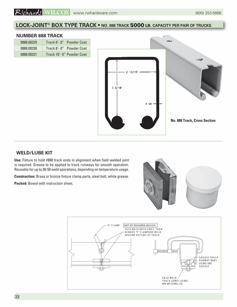
WELD/LUBE KIT
Use: Fixture to hold #888 track ends in alignment when field welded joint is required. Grease to be applied to track runways for smooth operation. Reusable for up to 30-50 weld operations, depending on temperature usage.
Construction: Brass or bronze fixture clamp parts, steel bolt, white grease.
Packed: Boxed with instruction sheet.
FIELD WELD TRACK JOINTS USING 888 WELDING JIG
GREASE TRACK RUNWAY BARSUSING 888 GREASE
TACK WELD BOTH SIDES, THENREMOVE "C" CLAMPAND WELDAROUND OUTSIDE OF TRACK
"C" CLAMP (NOT BY RICHARDS-WILCOX)
0888.00329 Track 6’- 0” Powder Coat
0888.00330 Track 8’- 0” Powder Coat
0888.00331 Track 10’- 0” Powder Coat
LOCK-JOINT® BOX TYPE TRACK • NO. 888 TRACK 5000 LB. CAPACITY PER PAIR OF TRUCKS
NUMBER 888 TRACK
No. 888 Track, Cross Section
23
(800) 253-5668www.rwhardware.com
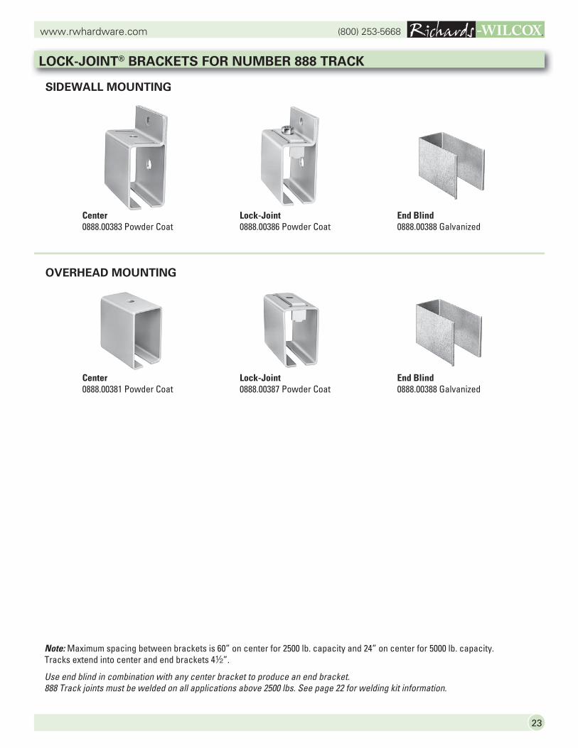
LOCK-JOINT® BRACKETS FOR NUMBER 888 TRACK
OVERHEAD MOUNTING
SIDEWALL MOUNTING
Center0888.00383 Powder Coat
Lock-Joint0888.00386 Powder Coat
End Blind0888.00388 Galvanized
Center0888.00381 Powder Coat
Lock-Joint0888.00387 Powder Coat
End Blind0888.00388 Galvanized
Note: Maximum spacing between brackets is 60” on center for 2500 lb. capacity and 24” on center for 5000 lb. capacity. Tracks extend into center and end brackets 42”.
Use end blind in combination with any center bracket to produce an end bracket.888 Track joints must be welded on all applications above 2500 lbs. See page 22 for welding kit information.
(800) 253-5668www.rwhardware.com
24
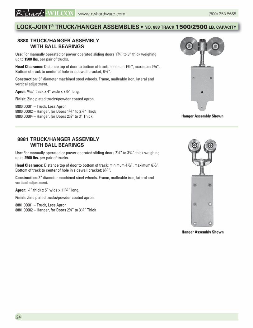
8880 TRUCK/HANGER ASSEMBLY
WITH BALL BEARINGS
Use: For manually operated or power operated sliding doors 1w” to 3” thick weighing up to 1500 lbs. per pair of trucks.
Head Clearance: Distance top of door to bottom of track; minimum 1a”, maximum 2w”.Bottom of track to center of hole in sidewall bracket; 6w”.
Construction: 3” diameter machined steel wheels. Frame, malleable iron, lateral and vertical adjustment.
Apron: 9/64” thick x 4” wide x 72” long.
Finish: Zinc plated trucks/powder coated apron.
8880.00001 – Truck, Less Apron8880.00002 – Hanger, for Doors 1w” to 24” Thick8880.00004 – Hanger, for Doors 24” to 3” Thick
8881 TRUCK/HANGER ASSEMBLY
WITH BALL BEARINGS
Use: For manually operated or power operated sliding doors 24” to 3w” thick weighing up to 2500 lbs. per pair of trucks.
Head Clearance: Distance top of door to bottom of track; minimum 42”, maximum 62”.Bottom of track to center of hole in sidewall bracket; 6w”.
Construction: 3” diameter machined steel wheels. Frame, malleable iron, lateral and vertical adjustment.
Apron: 4” thick x 5” wide x 11w” long.
Finish: Zinc plated trucks/powder coated apron.
8881.00001 – Truck, Less Apron8881.00002 – Hanger, for Doors 24” to 3w” Thick
LOCK-JOINT® TRUCK/HANGER ASSEMBLIES • NO. 888 TRACK 1500/2500 LB. CAPACITY
Hanger Assembly Shown
Hanger Assembly Shown
25
(800) 253-5668www.rwhardware.com
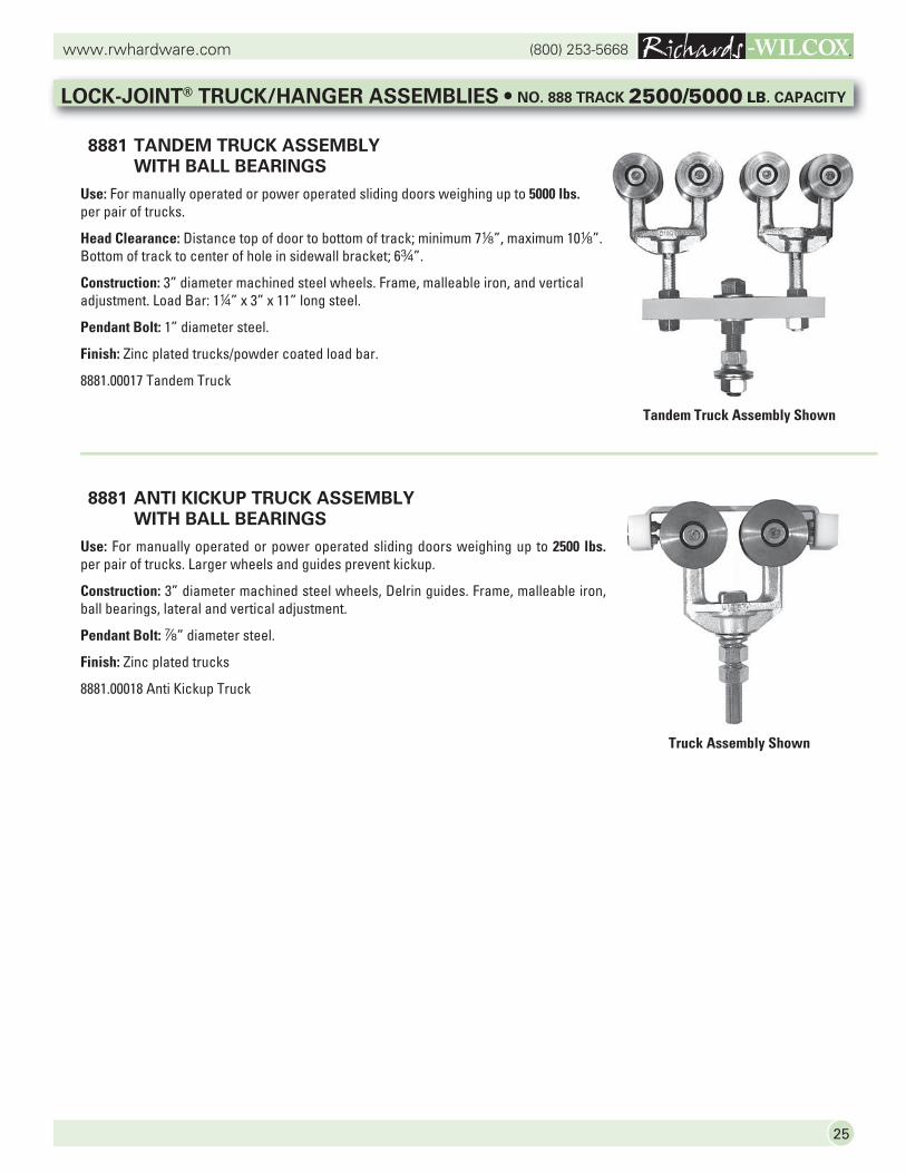
8881 TANDEM TRUCK ASSEMBLY
WITH BALL BEARINGS
Use: For manually operated or power operated sliding doors weighing up to 5000 lbs.per pair of trucks.
Head Clearance: Distance top of door to bottom of track; minimum 78”, maximum 108”. Bottom of track to center of hole in sidewall bracket; 6w”.
Construction: 3” diameter machined steel wheels. Frame, malleable iron, and vertical adjustment. Load Bar: 14” x 3” x 11” long steel.
Pendant Bolt: 1” diameter steel.
Finish: Zinc plated trucks/powder coated load bar.
8881.00017 Tandem Truck
8881 ANTI KICKUP TRUCK ASSEMBLY
WITH BALL BEARINGS
Use: For manually operated or power operated sliding doors weighing up to 2500 lbs.per pair of trucks. Larger wheels and guides prevent kickup.
Construction: 3” diameter machined steel wheels, Delrin guides. Frame, malleable iron, ball bearings, lateral and vertical adjustment.
Pendant Bolt: d” diameter steel.
Finish: Zinc plated trucks
8881.00018 Anti Kickup Truck
LOCK-JOINT® TRUCK/HANGER ASSEMBLIES • NO. 888 TRACK 2500/5000 LB. CAPACITY
Tandem Truck Assembly Shown
Truck Assembly Shown
(800) 253-5668www.rwhardware.com
26
Truck Assembly Shown
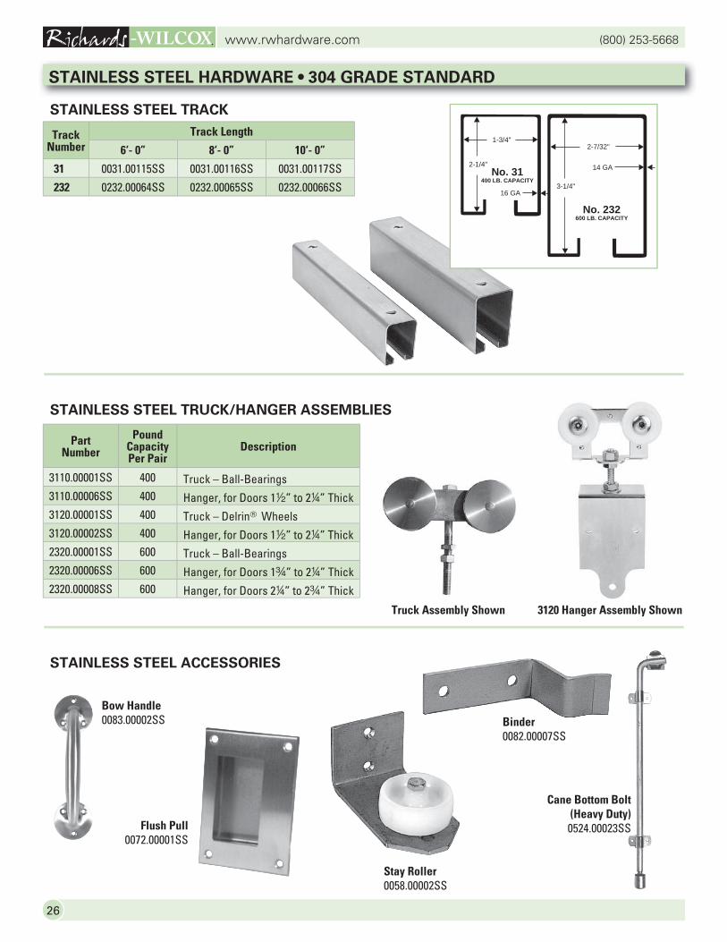
Bow Handle0083.00002SS
Flush Pull0072.00001SS
Binder0082.00007SS
Stay Roller0058.00002SS
Cane Bottom Bolt(Heavy Duty)0524.00023SS
Track Number
Track Length
6‘- 0” 8‘- 0” 10‘- 0”
31 0031.00115SS 0031.00116SS 0031.00117SS
232 0232.00064SS 0232.00065SS 0232.00066SS
Part Number
Pound Capacity Per Pair
Description
3110.00001SS 400 Truck – Ball-Bearings 3110.00006SS 400 Hanger, for Doors 12” to 24” Thick3120.00001SS 400 Truck – Delrin® Wheels 3120.00002SS 400 Hanger, for Doors 12” to 24” Thick2320.00001SS 600 Truck – Ball-Bearings 2320.00006SS 600 Hanger, for Doors 1w” to 24” Thick2320.00008SS 600 Hanger, for Doors 24” to 2w” Thick
3120 Hanger Assembly Shown
STAINLESS STEEL HARDWARE • 304 GRADE STANDARD
STAINLESS STEEL TRACK
STAINLESS STEEL TRUCK/HANGER ASSEMBLIES
STAINLESS STEEL ACCESSORIES
No. 232600 LB. CAPACITY
No. 31400 LB. CAPACITY
1-3/4"
2-1/4"
2-7/32"
3-1/4"
14 GA
16 GA
27
(800) 253-5668www.rwhardware.com
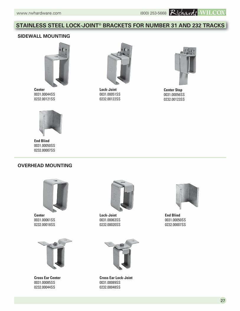
STAINLESS STEEL LOCK-JOINT® BRACKETS FOR NUMBER 31 AND 232 TRACKS
OVERHEAD MOUNTING
SIDEWALL MOUNTING
Center0031.00044SS0232.00121SS
Lock-Joint0031.00051SS0232.00122SS
End Blind0031.00050SS0232.00007SS
Center0031.00061SS0232.00018SS
Lock-Joint0031.00063SS0232.00020SS
End Blind0031.00050SS0232.00007SS
Cross Ear Center0031.00085SS0232.00044SS
Cross Ear Lock-Joint0031.00089SS0232.00048SS
Center Stop0031.00056SS0232.00123SS
(800) 253-5668www.rwhardware.com
28
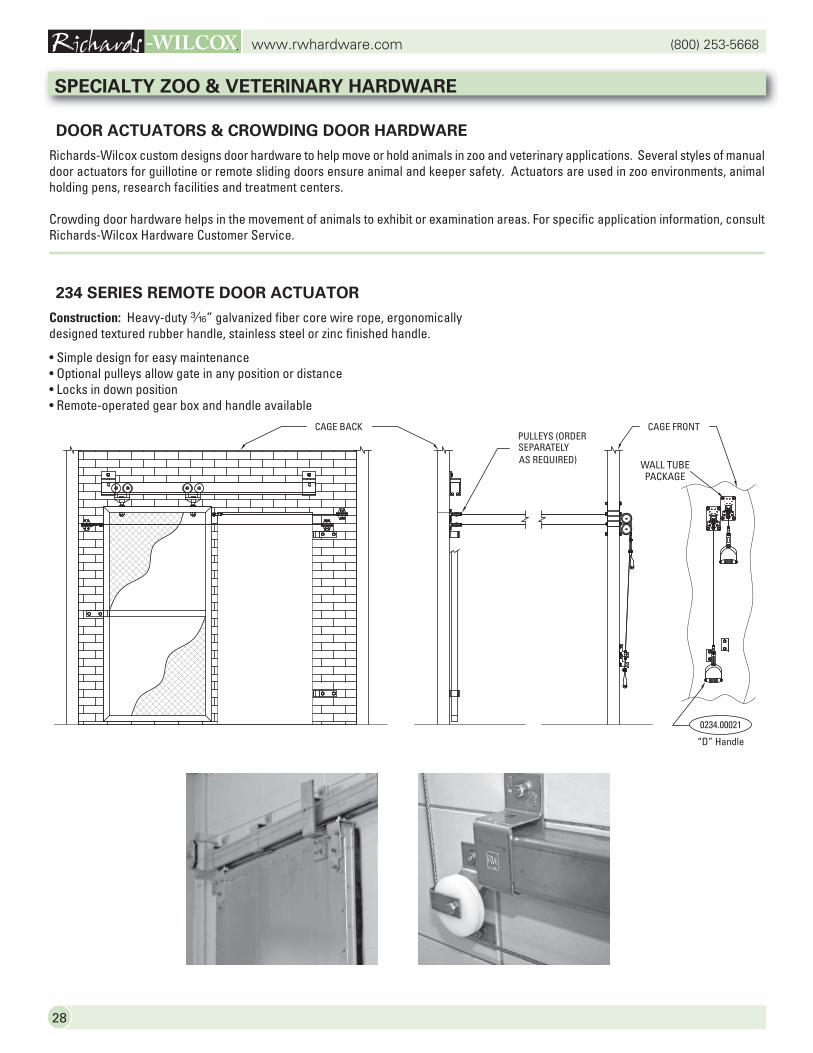
DOOR ACTUATORS & CROWDING DOOR HARDWARE
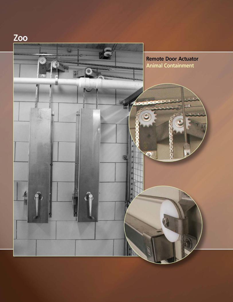
Richards-Wilcox custom designs door hardware to help move or hold animals in zoo and veterinary applications. Several styles of manual door actuators for guillotine or remote sliding doors ensure animal and keeper safety. Actuators are used in zoo environments, animal holding pens, research facilities and treatment centers.
Crowding door hardware helps in the movement of animals to exhibit or examination areas. For specific application information, consult Richards-Wilcox Hardware Customer Service.
234 SERIES REMOTE DOOR ACTUATOR
Construction: Heavy-duty x” galvanized fiber core wire rope, ergonomically designed textured rubber handle, stainless steel or zinc finished handle.
• Simple design for easy maintenance• Optional pulleys allow gate in any position or distance• Locks in down position• Remote-operated gear box and handle available
SPECIALTY ZOO & VETERINARY HARDWARE
R
RWR
RW
CAGE BACK CAGE FRONT
WALL TUBEPACKAGE
0234.00021
“D” Handle
PULLEYS (ORDERSEPARATELY AS REQUIRED)
29
(800) 253-5668www.rwhardware.com
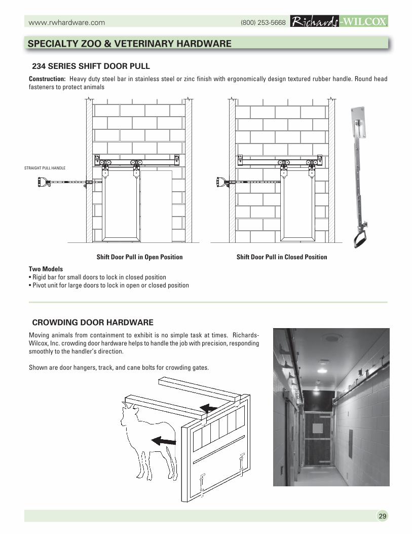
234 SERIES SHIFT DOOR PULL
Construction: Heavy duty steel bar in stainless steel or zinc finish with ergonomically design textured rubber handle. Round head fasteners to protect animals
Two Models• Rigid bar for small doors to lock in closed position• Pivot unit for large doors to lock in open or closed position
CROWDING DOOR HARDWARE
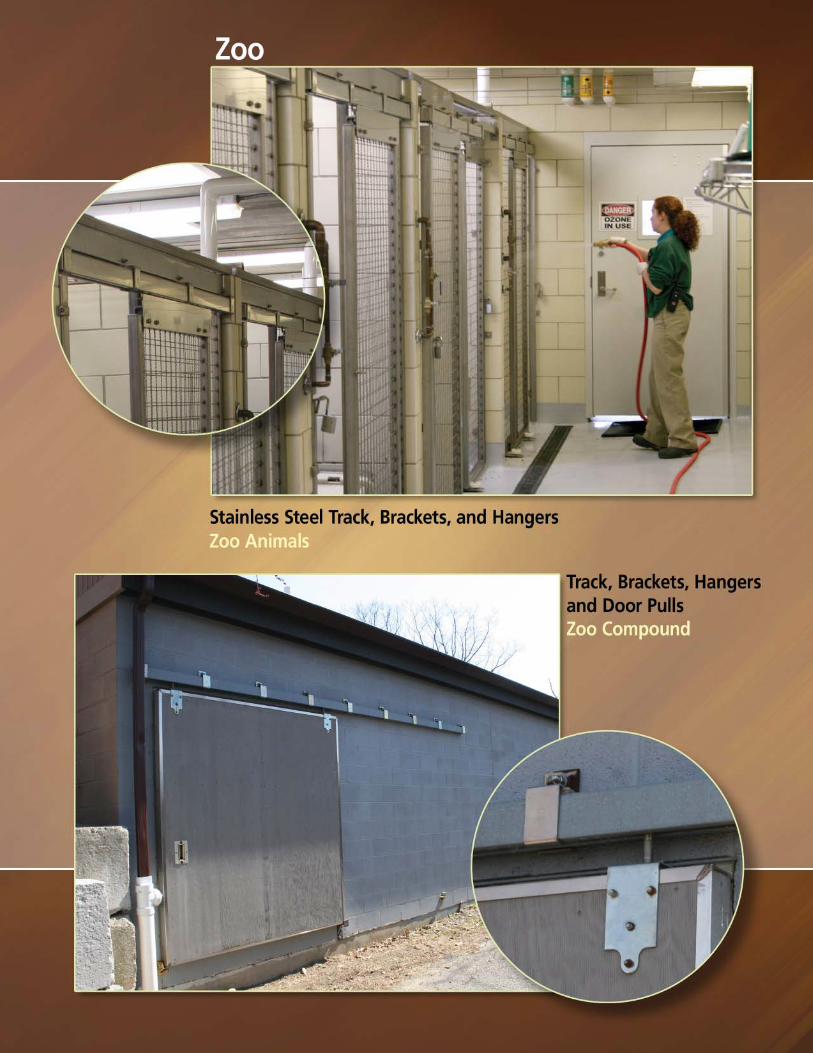
Moving animals from containment to exhibit is no simple task at times. Richards-Wilcox, Inc. crowding door hardware helps to handle the job with precision, responding smoothly to the handler’s direction.
Shown are door hangers, track, and cane bolts for crowding gates.
SPECIALTY ZOO & VETERINARY HARDWARE
RWR
RWR R
RW RWR
0234.00005
STRAIGHT PULL HANDLE
0234.00016
WALL TUBE PACKAGE
Shift Door Pull in Open Position Shift Door Pull in Closed Position
(800) 253-5668www.rwhardware.com
30
SPECIALTY ZOO & VETERINARY HARDWARE
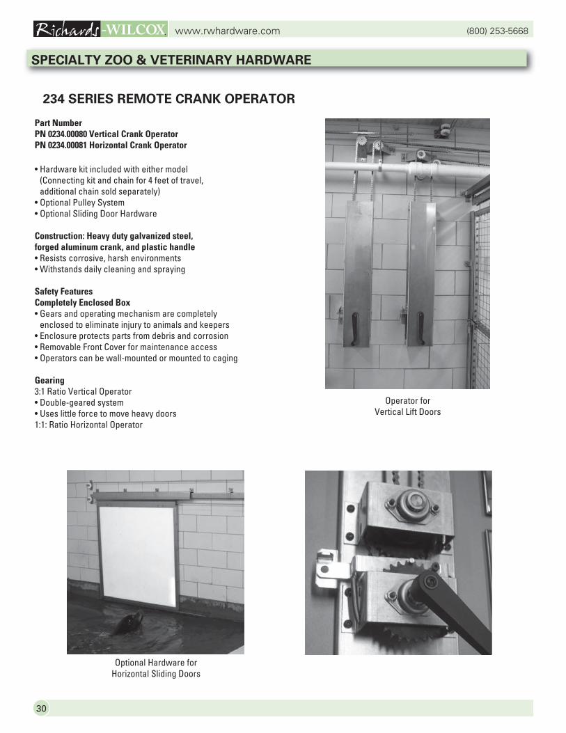
234 SERIES REMOTE CRANK OPERATOR
Part NumberPN 0234.00080 Vertical Crank OperatorPN 0234.00081 Horizontal Crank Operator
• Hardware kit included with either model(Connecting kit and chain for 4 feet of travel,additional chain sold separately)
• Optional Pulley System • Optional Sliding Door Hardware
Construction: Heavy duty galvanized steel,forged aluminum crank, and plastic handle• Resists corrosive, harsh environments• Withstands daily cleaning and spraying
Safety FeaturesCompletely Enclosed Box• Gears and operating mechanism are completely
enclosed to eliminate injury to animals and keepers• Enclosure protects parts from debris and corrosion• Removable Front Cover for maintenance access• Operators can be wall-mounted or mounted to caging
Gearing3:1 Ratio Vertical Operator• Double-geared system• Uses little force to move heavy doors1:1: Ratio Horizontal Operator
Operator forVertical Lift Doors
Optional Hardware forHorizontal Sliding Doors
31
(800) 253-5668www.rwhardware.com
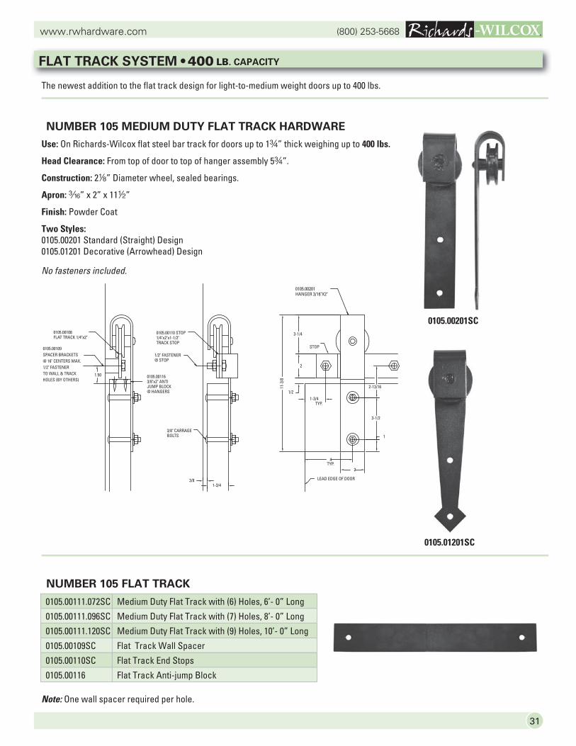
The newest addition to the flat track design for light-to-medium weight doors up to 400 lbs.
NUMBER 105 MEDIUM DUTY FLAT TRACK HARDWARE
Use: On Richards-Wilcox flat steel bar track for doors up to 1w” thick weighing up to 400 lbs.
Head Clearance: From top of door to top of hanger assembly 5w”.
Construction: 28” Diameter wheel, sealed bearings.
Apron: x” x 2” x 112”
Finish: Powder Coat
Two Styles: 0105.00201 Standard (Straight) Design0105.01201 Decorative (Arrowhead) Design
NUMBER 105 FLAT TRACK
0105.00201SC
0105.01201SC
1-3/43/8
1.50
0105.00108
HOLES (BY OTHERS)TO WALL & TRACK1/2" FASTENER@ 16" CENTERS MAX.SPACER BRACKETS
FLAT TRACK 1/4"x2"
BOLTS3/8" CARRAGE
@ STOP1/2" FASTENER
@ HANGERSJUMP BLOCK3/8"x2" ANTI
1/4"x2"x1-1/2"TRACK STOP
0105.00110 STOP
LEAD EDGE OF DOOR
2
4
3-1/4
2
1/2
11-3
/8
1-3/4TYP.
TYP.
STOP
0105.00201HANGER 3/16"X2"
2-13/16
3-1/2
1
0105.00109
0105.00116
Note: One wall spacer required per hole.
FLAT TRACK SYSTEM • 400 LB. CAPACITY
0105.00111.072SC Medium Duty Flat Track with (6) Holes, 6’- 0” Long
0105.00111.096SC Medium Duty Flat Track with (7) Holes, 8’- 0” Long
0105.00111.120SC Medium Duty Flat Track with (9) Holes, 10’- 0” Long
0105.00109SC Flat Track Wall Spacer
0105.00110SC Flat Track End Stops
0105.00116 Flat Track Anti-jump Block
No fasteners included.
(800) 253-5668www.rwhardware.com
32
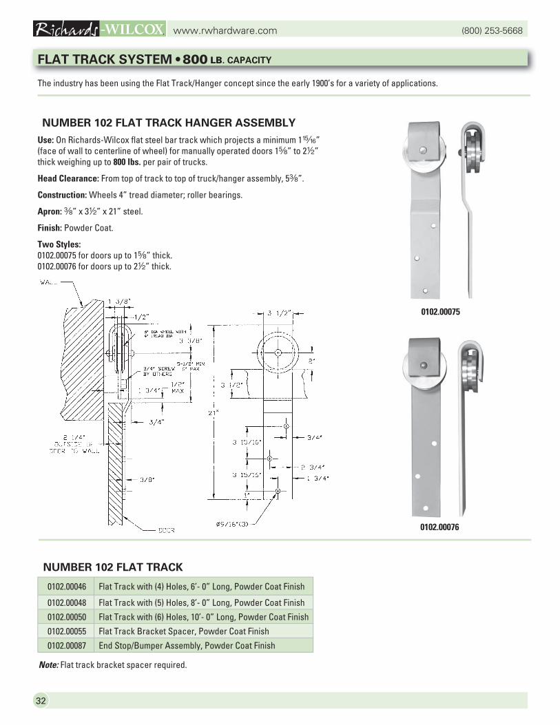
The industry has been using the Flat Track/Hanger concept since the early 1900’s for a variety of applications.
NUMBER 102 FLAT TRACK HANGER ASSEMBLY
Use: On Richards-Wilcox flat steel bar track which projects a minimum 1,” (face of wall to centerline of wheel) for manually operated doors 1s” to 22” thick weighing up to 800 lbs. per pair of trucks.
Head Clearance: From top of track to top of truck/hanger assembly, 5a”.
Construction: Wheels 4” tread diameter; roller bearings.
Apron: a” x 32” x 21” steel.
Finish: Powder Coat.
Two Styles:0102.00075 for doors up to 1s” thick.0102.00076 for doors up to 22” thick.
NUMBER 102 FLAT TRACK
0102.00075
0102.00076
Note: Flat track bracket spacer required.
FLAT TRACK SYSTEM • 800 LB. CAPACITY
0102.00046 Flat Track with (4) Holes, 6’- 0” Long, Powder Coat Finish
0102.00048 Flat Track with (5) Holes, 8’- 0” Long, Powder Coat Finish
0102.00050 Flat Track with (6) Holes, 10’- 0” Long, Powder Coat Finish
0102.00055 Flat Track Bracket Spacer, Powder Coat Finish
0102.00087 End Stop/Bumper Assembly, Powder Coat Finish

33
(800) 253-5668www.rwhardware.com
GUIDE ROLLERS
0054.00003 GUIDE ROLLER
Wheel, high impact nylon, 22” diameter. Covered with steel frame, 6” long x 2w” high x 2” wide.
Finish: Zinc plated.
No fasteners included.
0058.00002 GUIDE ROLLER
For doors 12” to 2w” thick. Adjustable and reversible. Wheel, high impact nylon, 22” diameter. Steel frame, 42” long x 22” high x 14” wide.
Finish: Powder Coat.
No fasteners included.
0059.00007 GUIDE ROLLER (With Back Brace)
Extra high to suit door on incline track. Wheel, 3” diameter. Steel frame, 22” wide x x” thick. Distance from floor to center of wheel, 8a”. Overall height, 92”.
Finish: Powder Coat.
No fasteners included.
0153.00005 GUIDE ROLLER
Adjustable and reversible for inside or outside doors 14” to 3” thick. Wheel, 3” diameter.
Construction: Steel frame.
Finish: Powder Coat.
No fasteners included.
0154.00004 GUIDE ROLLER
Wheel, 3” diameter. Heavy steel frame with slotted screw holes provides means for adjustment.7” long x 3” high x 5” wide.
Construction: Steel Frame.
Finish: Powder Coat.
No fasteners included.
DOOR HARDWARE
(800) 253-5668www.rwhardware.com
34
DOOR PULLS
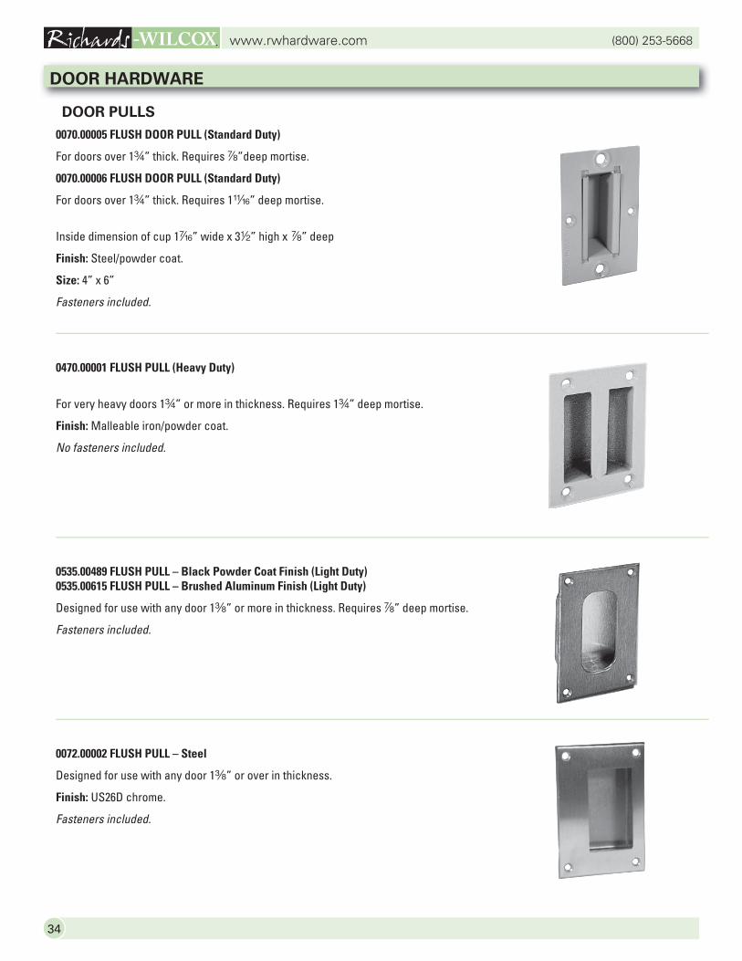
0070.00005 FLUSH DOOR PULL (Standard Duty)
For doors over 1w” thick. Requires d”deep mortise.
0070.00006 FLUSH DOOR PULL (Standard Duty)
For doors over 1w” thick. Requires 1n” deep mortise.
Inside dimension of cup 1v” wide x 32” high x d” deep
Finish: Steel/powder coat.
Size: 4” x 6”
Fasteners included.
0470.00001 FLUSH PULL (Heavy Duty)
For very heavy doors 1w” or more in thickness. Requires 1w” deep mortise.
Finish: Malleable iron/powder coat.
No fasteners included.
0535.00489 FLUSH PULL – Black Powder Coat Finish (Light Duty)0535.00615 FLUSH PULL – Brushed Aluminum Finish (Light Duty)
Designed for use with any door 1a” or more in thickness. Requires d” deep mortise.
Fasteners included.
0072.00002 FLUSH PULL – Steel
Designed for use with any door 1a” or over in thickness.
Finish: US26D chrome.
Fasteners included.
DOOR HARDWARE
35
(800) 253-5668www.rwhardware.com
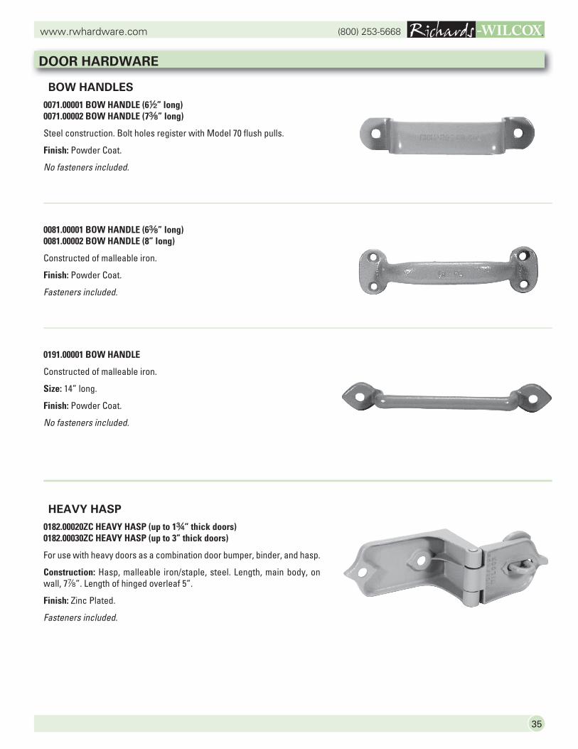
BOW HANDLES
0071.00001 BOW HANDLE (62” long)0071.00002 BOW HANDLE (7a” long)
Steel construction. Bolt holes register with Model 70 flush pulls.
Finish: Powder Coat.
No fasteners included.
0081.00001 BOW HANDLE (6a” long)0081.00002 BOW HANDLE (8” long)
Constructed of malleable iron.
Finish: Powder Coat.
Fasteners included.
0191.00001 BOW HANDLE
Constructed of malleable iron.
Size: 14” long.
Finish: Powder Coat.
No fasteners included.
HEAVY HASP
0182.00020ZC HEAVY HASP (up to 1w” thick doors)0182.00030ZC HEAVY HASP (up to 3” thick doors)
For use with heavy doors as a combination door bumper, binder, and hasp.
Construction: Hasp, malleable iron/staple, steel. Length, main body, on wall, 7d”. Length of hinged overleaf 5”.
Finish: Zinc Plated.
Fasteners included.
DOOR HARDWARE
(800) 253-5668www.rwhardware.com
36
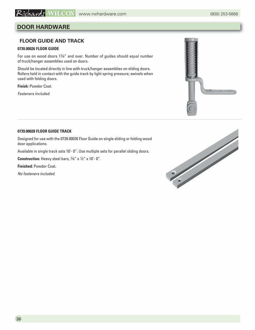
FLOOR GUIDE AND TRACK
0739.00026 FLOOR GUIDE
For use on wood doors 1a” and over. Number of guides should equal number of truck/hanger assemblies used on doors.
Should be located directly in line with truck/hanger assemblies on sliding doors. Rollers held in contact with the guide track by light spring pressure; swivels when used with folding doors.
Finish: Powder Coat.
Fasteners included.
0739.00028 FLOOR GUIDE TRACK
Designed for use with the 0739.00026 Floor Guide on single sliding or folding wood door applications.
Available in single track sets 10’- 0”. Use multiple sets for parallel sliding doors.
Construction: Heavy steel bars, a” x 2” x 10’- 0”.
Finished: Powder Coat.
No fasteners included.
DOOR HARDWARE
37
(800) 253-5668www.rwhardware.com
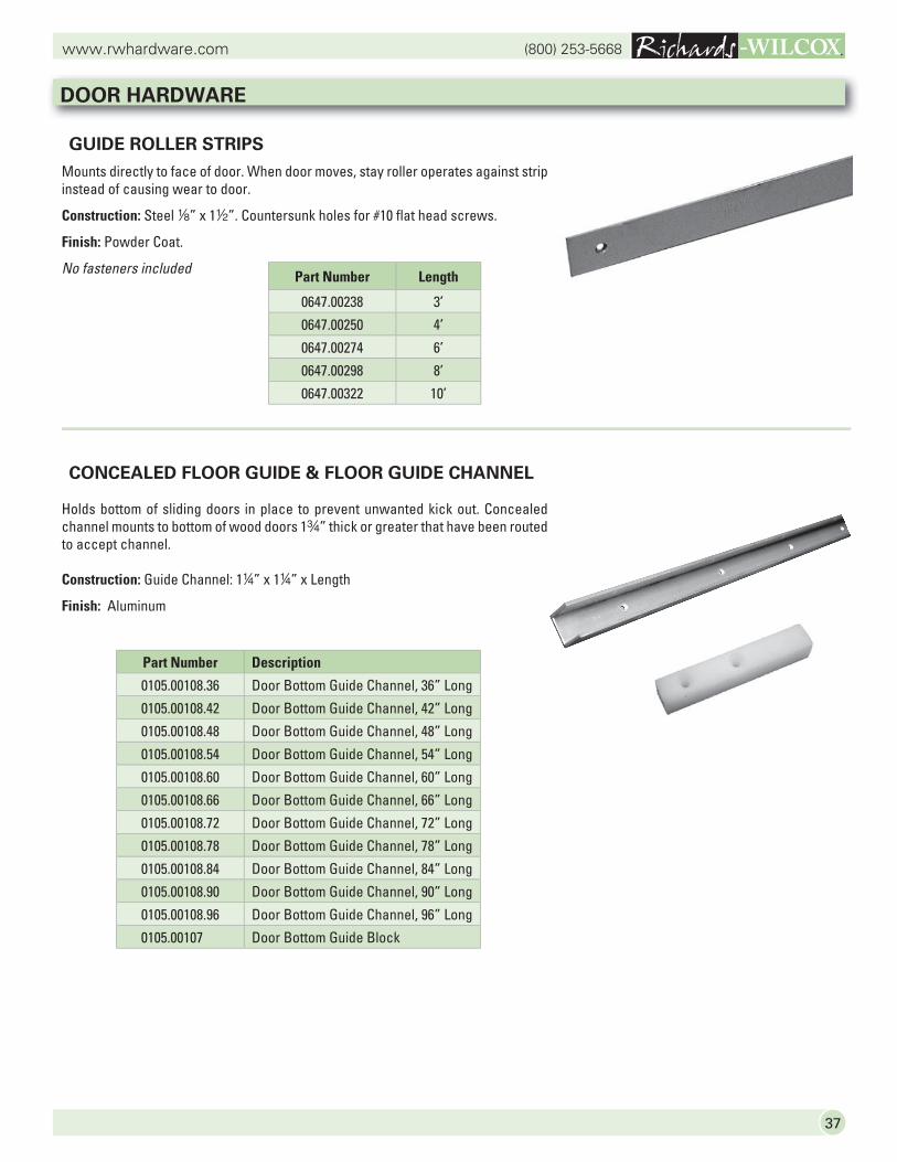
GUIDE ROLLER STRIPS
Mounts directly to face of door. When door moves, stay roller operates against strip instead of causing wear to door.
Construction: Steel 8” x 12”. Countersunk holes for #10 flat head screws.
Finish: Powder Coat.
No fasteners included
CONCEALED FLOOR GUIDE & FLOOR GUIDE CHANNEL
Holds bottom of sliding doors in place to prevent unwanted kick out. Concealed channel mounts to bottom of wood doors 1w” thick or greater that have been routed to accept channel.
Construction: Guide Channel: 14” x 14” x Length
Finish: Aluminum
DOOR HARDWARE
Part Number Length
0647.00238 3’
0647.00250 4’
0647.00274 6’
0647.00298 8’
0647.00322 10’
Part Number Description
0105.00108.36 Door Bottom Guide Channel, 36” Long
0105.00108.42 Door Bottom Guide Channel, 42” Long
0105.00108.48 Door Bottom Guide Channel, 48” Long
0105.00108.54 Door Bottom Guide Channel, 54” Long
0105.00108.60 Door Bottom Guide Channel, 60” Long
0105.00108.66 Door Bottom Guide Channel, 66” Long
0105.00108.72 Door Bottom Guide Channel, 72” Long
0105.00108.78 Door Bottom Guide Channel, 78” Long
0105.00108.84 Door Bottom Guide Channel, 84” Long
0105.00108.90 Door Bottom Guide Channel, 90” Long
0105.00108.96 Door Bottom Guide Channel, 96” Long
0105.00107 Door Bottom Guide Block
(800) 253-5668www.rwhardware.com
38
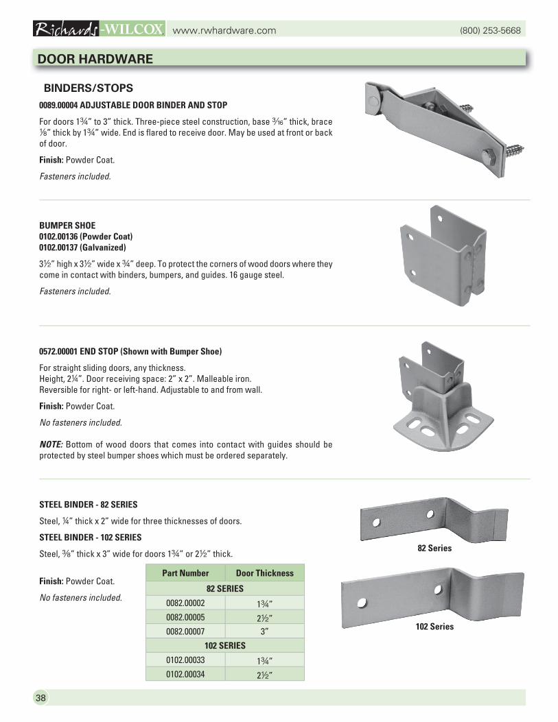
BINDERS/STOPS
0089.00004 ADJUSTABLE DOOR BINDER AND STOP
For doors 1w” to 3” thick. Three-piece steel construction, base x” thick, brace 8” thick by 1w” wide. End is flared to receive door. May be used at front or back of door.
Finish: Powder Coat.
Fasteners included.
BUMPER SHOE0102.00136 (Powder Coat)0102.00137 (Galvanized)
32” high x 32” wide x w” deep. To protect the corners of wood doors where they come in contact with binders, bumpers, and guides. 16 gauge steel.
Fasteners included.
0572.00001 END STOP (Shown with Bumper Shoe)
For straight sliding doors, any thickness.Height, 24”. Door receiving space: 2” x 2”. Malleable iron.Reversible for right- or left-hand. Adjustable to and from wall.
Finish: Powder Coat.
No fasteners included.
NOTE: Bottom of wood doors that comes into contact with guides should be protected by steel bumper shoes which must be ordered separately.
STEEL BINDER - 82 SERIES
Steel, 4” thick x 2” wide for three thicknesses of doors.
STEEL BINDER - 102 SERIES
Steel, a” thick x 3” wide for doors 1w” or 22” thick.
Finish: Powder Coat.
No fasteners included.
DOOR HARDWARE
Part Number Door Thickness
82 SERIES
0082.00002 1w”0082.00005 22”0082.00007 3”
102 SERIES
0102.00033 1w”0102.00034 22”
82 Series
102 Series
39
(800) 253-5668www.rwhardware.com
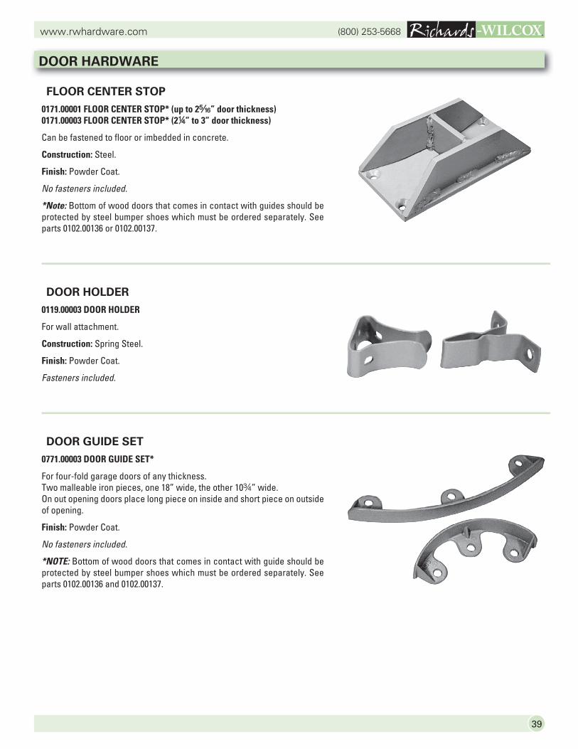
FLOOR CENTER STOP
0171.00001 FLOOR CENTER STOP* (up to 2c” door thickness)0171.00003 FLOOR CENTER STOP* (24” to 3” door thickness)
Can be fastened to floor or imbedded in concrete.
Construction: Steel.
Finish: Powder Coat.
No fasteners included.
*Note: Bottom of wood doors that comes in contact with guides should be protected by steel bumper shoes which must be ordered separately. See parts 0102.00136 or 0102.00137.
DOOR HOLDER
0119.00003 DOOR HOLDER
For wall attachment.
Construction: Spring Steel.
Finish: Powder Coat.
Fasteners included.
DOOR GUIDE SET
0771.00003 DOOR GUIDE SET*
For four-fold garage doors of any thickness. Two malleable iron pieces, one 18” wide, the other 10w” wide.On out opening doors place long piece on inside and short piece on outside of opening.
Finish: Powder Coat.
No fasteners included.
*NOTE: Bottom of wood doors that comes in contact with guide should be protected by steel bumper shoes which must be ordered separately. See parts 0102.00136 and 0102.00137.
DOOR HARDWARE
(800) 253-5668www.rwhardware.com
40
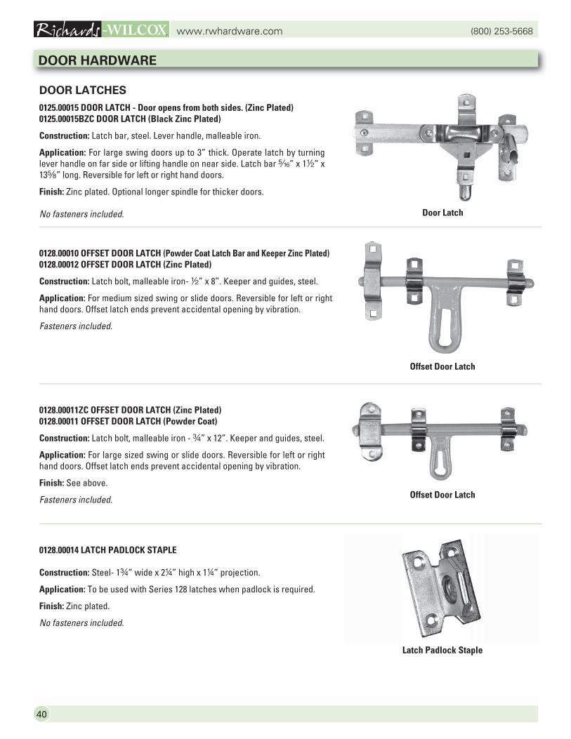
DOOR LATCHES
0125.00015 DOOR LATCH - Door opens from both sides. (Zinc Plated)0125.00015BZC DOOR LATCH (Black Zinc Plated)
Construction: Latch bar, steel. Lever handle, malleable iron.
Application: For large swing doors up to 3” thick. Operate latch by turning lever handle on far side or lifting handle on near side. Latch bar c” x 12” x 13s” long. Reversible for left or right hand doors.
Finish: Zinc plated. Optional longer spindle for thicker doors.
No fasteners included.
0128.00010 OFFSET DOOR LATCH (Powder Coat Latch Bar and Keeper Zinc Plated)0128.00012 OFFSET DOOR LATCH (Zinc Plated)
Construction: Latch bolt, malleable iron- 2” x 8”. Keeper and guides, steel.
Application: For medium sized swing or slide doors. Reversible for left or right hand doors. Offset latch ends prevent accidental opening by vibration.
Fasteners included.
0128.00011ZC OFFSET DOOR LATCH (Zinc Plated)0128.00011 OFFSET DOOR LATCH (Powder Coat)
Construction: Latch bolt, malleable iron - w” x 12”. Keeper and guides, steel.
Application: For large sized swing or slide doors. Reversible for left or right hand doors. Offset latch ends prevent accidental opening by vibration.
Finish: See above.
Fasteners included.
0128.00014 LATCH PADLOCK STAPLE
Construction: Steel- 1w” wide x 24” high x 14” projection.
Application: To be used with Series 128 latches when padlock is required.
Finish: Zinc plated.
No fasteners included.
DOOR HARDWARE
Door Latch
Offset Door Latch
Offset Door Latch
Latch Padlock Staple
41
(800) 253-5668www.rwhardware.com
DOOR LATCHES
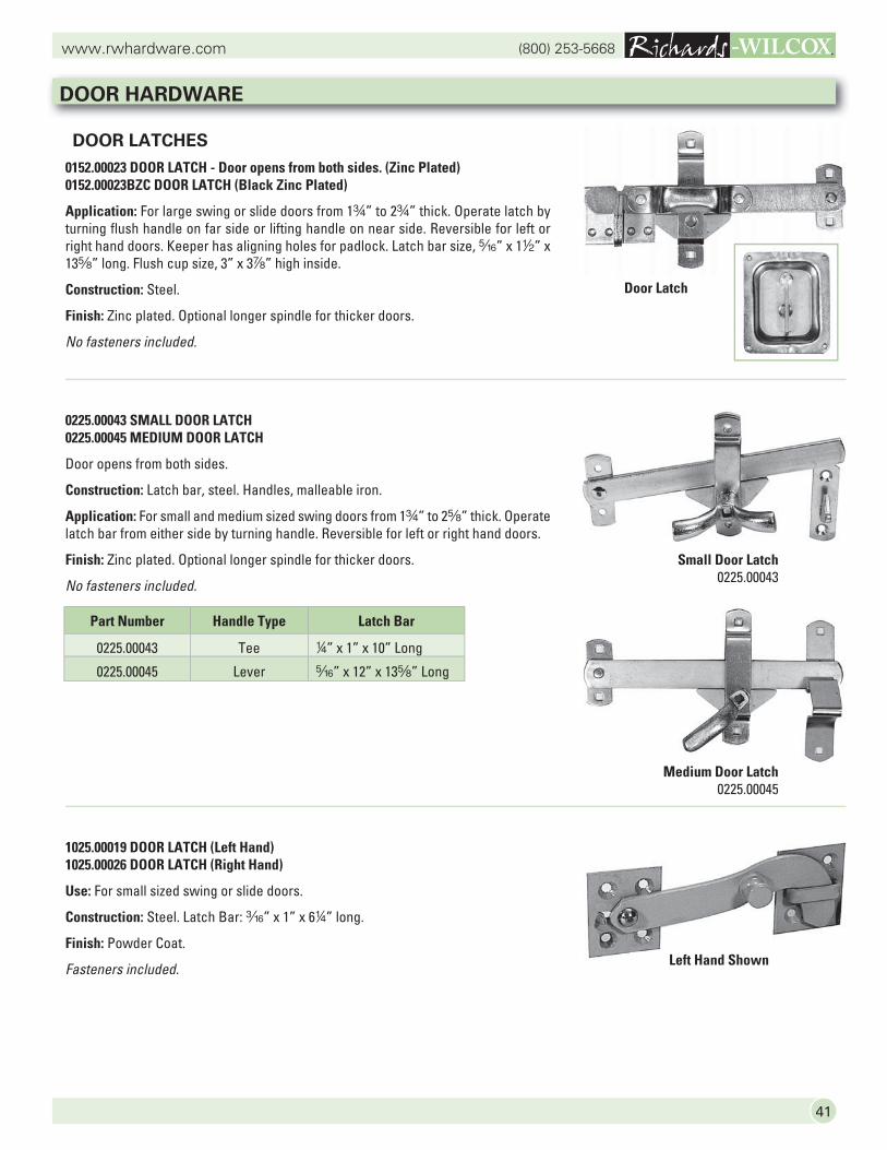
0152.00023 DOOR LATCH - Door opens from both sides. (Zinc Plated)0152.00023BZC DOOR LATCH (Black Zinc Plated)
Application: For large swing or slide doors from 1w” to 2w” thick. Operate latch by turning flush handle on far side or lifting handle on near side. Reversible for left or right hand doors. Keeper has aligning holes for padlock. Latch bar size, c” x 12” x 13s” long. Flush cup size, 3” x 3d” high inside.
Construction: Steel.
Finish: Zinc plated. Optional longer spindle for thicker doors.
No fasteners included.
0225.00043 SMALL DOOR LATCH0225.00045 MEDIUM DOOR LATCH
Door opens from both sides.
Construction: Latch bar, steel. Handles, malleable iron.
Application: For small and medium sized swing doors from 1w” to 2s” thick. Operate latch bar from either side by turning handle. Reversible for left or right hand doors.
Finish: Zinc plated. Optional longer spindle for thicker doors.
No fasteners included.
1025.00019 DOOR LATCH (Left Hand)1025.00026 DOOR LATCH (Right Hand)
Use: For small sized swing or slide doors.
Construction: Steel. Latch Bar: x” x 1” x 64” long.
Finish: Powder Coat.
Fasteners included.
DOOR HARDWARE
Part Number Handle Type Latch Bar
0225.00043 Tee 4” x 1” x 10” Long
0225.00045 Lever c” x 12” x 13s” Long
Small Door Latch0225.00043
Medium Door Latch0225.00045
Left Hand Shown
Door Latch
(800) 253-5668www.rwhardware.com
42
SPRING AND CANE BOLTS
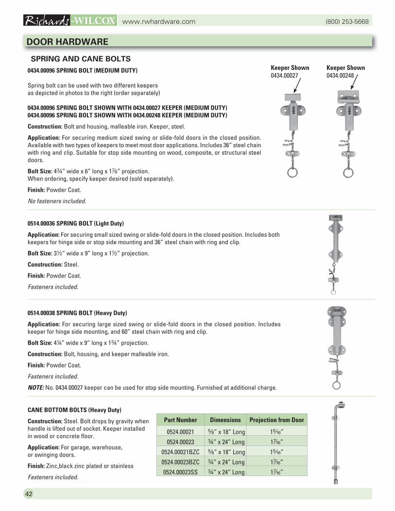
0434.00096 SPRING BOLT (MEDIUM DUTY)
Spring bolt can be used with two different keepers as depicted in photos to the right (order separately)
0434.00096 SPRING BOLT SHOWN WITH 0434.00027 KEEPER (MEDIUM DUTY)0434.00096 SPRING BOLT SHOWN WITH 0434.00248 KEEPER (MEDIUM DUTY)
Construction: Bolt and housing, malleable iron. Keeper, steel.
Application: For securing medium sized swing or slide-fold doors in the closed position. Available with two types of keepers to meet most door applications. Includes 36” steel chain with ring and clip. Suitable for stop side mounting on wood, composite, or structural steel doors.
Bolt Size: 4w” wide x 6” long x 1d” projection. When ordering, specify keeper desired (sold separately).
Finish: Powder Coat.
No fasteners included.
0514.00036 SPRING BOLT (Light Duty)
Application: For securing small sized swing or slide-fold doors in the closed position. Includes both keepers for hinge side or stop side mounting and 36” steel chain with ring and clip.
Bolt Size: 32” wide x 9” long x 12” projection.
Construction: Steel.
Finish: Powder Coat.
Fasteners included.
0514.00038 SPRING BOLT (Heavy Duty)
Application: For securing large sized swing or slide-fold doors in the closed position. Includes keeper for hinge side mounting, and 60” steel chain with ring and clip.
Bolt Size: 44” wide x 9” long x 1w” projection.
Construction: Bolt, housing, and keeper malleable iron.
Finish: Powder Coat.
Fasteners included.
NOTE: No. 0434.00027 keeper can be used for stop side mounting. Furnished at additional charge.
CANE BOTTOM BOLTS (Heavy Duty)
Construction: Steel. Bolt drops by gravity when handle is lifted out of socket. Keeper installed in wood or concrete floor.
Application: For garage, warehouse, or swinging doors.
Finish: Zinc,black zinc plated or stainless
Fasteners included.
Keeper Shown0434.00027
Keeper Shown0434.00248
DOOR HARDWARE
Part Number Dimensions Projection from Door
0524.00021 s” x 18” Long 1c”
0524.00023 w” x 24” Long 1v”
0524.00021BZC s” x 18” Long 1c”
0524.00023BZC w” x 24” Long 1v”
0524.00023SS w” x 24” Long 1v”
43
(800) 253-5668www.rwhardware.com
DOOR HARDWARE
Part # Description Weight per Unit
1028.00330 Cremone Bolt Auxiliary Handle Package 10 lb.
1028.00340 Cremone Bolt Key Lock/Knob Package with Auxiliary Handle Included 12 lb.
1028.00350 Cremone Bolt Key Lock Both Sides Package with Auxiliary Handle Included 14 lb.
1028.00360 Cremone Bolt Heavy Hasp Package 8 lb.
1028.00370 Cremone Bolt 3’ Add-On Package 15 lb.
1028.00310.008 Heavy Duty Cremone Bolt – Zinc Plated – 6’- 8” to 8’ Door Height 50 lb.
1028.00310.009 Heavy Duty Cremone Bolt – Zinc Plated – 8’ to 9’- 6’ Door Height 50 lb.
1028.00310.011 Heavy Duty Cremone Bolt – Zinc Plated – 9’- 6” to 11’ Door Height 50 lb.
1028.00310.012 Heavy Duty Cremone Bolt – Zinc Plated – 11’ to 12’- 6” Door Height 50 lb.
1028.00310.014 Heavy Duty Cremone Bolt – Zinc Plated – 12’- 6” to 14’ Door Height 53 lb.
1028.00310.015 Heavy Duty Cremone Bolt – Zinc Plated – 14’ to 15’- 6” Door Height 53 lb.
1028.00310.017 Heavy Duty Cremone Bolt – Zinc Plated – 15’- 6” to 17’ Door Height 53 lb.
1028.00310.018 Heavy Duty Cremone Bolt – Zinc Plated – 17’ to 18’- 6” Door Height 53 lb.
1028.00310.020 Heavy Duty Cremone Bolt – Zinc Plated – 18’- 6” to 20’ Door Height 53 lb.
1028.00310.021 Heavy Duty Cremone Bolt – Zinc Plated – 20’ to 21’- 6” Door Height 53 lb.
1028.00310.023 Heavy Duty Cremone Bolt – Zinc Plated – 21’- 6” to 23’ Door Height 53 lb.
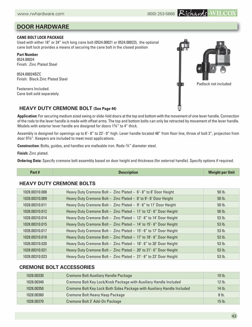
CANE BOLT LOCK PACKAGEUsed with either 18” or 24” inch long cane bolt (0524.00021 or 0524.00023), the optional cane bolt lock provides a means of securing the cane bolt in the closed position
Part Number0524.00024Finish: Zinc Plated Steel
0524.00024BZCFinish: Black Zinc Plated Steel
Fasteners Included.Cane bolt sold separately.
Padlock not included
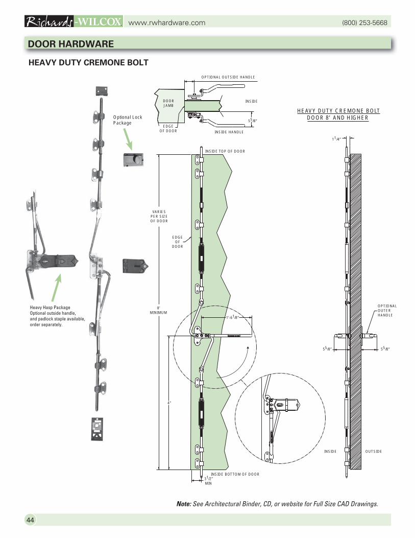
HEAVY DUTY CREMONE BOLT (See Page 44)
Application: For securing medium sized swing or slide-fold doors at the top and bottom with the movement of one lever handle. Connection of the rods to the lever handle is made with offset arms. The top and bottom bolts can only be retracted by movement of the lever handle. Models with exterior lever handle are designed for doors 1w” to 4” thick.
Assembly is designed for openings up to 6’- 8” to 23’- 0” high. Lever handle located 48” from floor line, throw of bolt 3”, projection from door 5s”. Keepers are included to meet most applications.
Construction: Bolts, guides, and handles are malleable iron. Rods-w” diameter steel.
Finish: Zinc plated.
Ordering Data: Specify cremone bolt assembly based on door height and thickness (for external handle). Specify options if required.
HEAVY DUTY CREMONE BOLTS
CREMONE BOLT ACCESSORIES
(800) 253-5668www.rwhardware.com
44
Optional Lock Package
Note: See Architectural Binder, CD, or website for Full Size CAD Drawings.
HEAVY DUTY CREMONE BOLT
DOOR HARDWARE
OPTIONAL OUTSIDE HANDLE
INSIDE HANDLE
55/8”
11/4”
INSIDE OUTSIDE
OPTIONALOUTERHANDLE
INSIDE DOORJAMB
EDGEOF DOOR
EDGEOF
DOOR
VARIESPER SIZEOF DOOR
8’MINIMUM
1’-61/8”
4”
HEAVY DUTY CREMONE BOLTDOOR 8’ AND HIGHER
55/8” 55/8”
INSIDE TOP OF DOOR
INSIDE BOTTOM OF DOOR31/2”MIN
Heavy Hasp PackageOptional outside handle,and padlock staple available,order separately.
45
(800) 253-5668www.rwhardware.com
DOOR HARDWARE
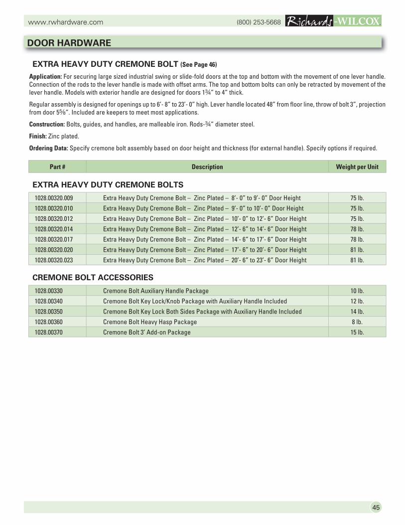
EXTRA HEAVY DUTY CREMONE BOLT (See Page 46)
Application: For securing large sized industrial swing or slide-fold doors at the top and bottom with the movement of one lever handle. Connection of the rods to the lever handle is made with offset arms. The top and bottom bolts can only be retracted by movement of the lever handle. Models with exterior handle are designed for doors 1w” to 4” thick.
Regular assembly is designed for openings up to 6’- 8” to 23’- 0” high. Lever handle located 48” from floor line, throw of bolt 3”, projection from door 5s”. Included are keepers to meet most applications.
Construction: Bolts, guides, and handles, are malleable iron. Rods-w” diameter steel.
Finish: Zinc plated.
Ordering Data: Specify cremone bolt assembly based on door height and thickness (for external handle). Specify options if required.
EXTRA HEAVY DUTY CREMONE BOLTS
CREMONE BOLT ACCESSORIES
Part # Description Weight per Unit
1028.00320.009 Extra Heavy Duty Cremone Bolt – Zinc Plated – 8’- 0” to 9’- 0” Door Height 75 lb.
1028.00320.010 Extra Heavy Duty Cremone Bolt – Zinc Plated – 9’- 0” to 10’- 0” Door Height 75 lb.
1028.00320.012 Extra Heavy Duty Cremone Bolt – Zinc Plated – 10’- 0” to 12’- 6” Door Height 75 lb.
1028.00320.014 Extra Heavy Duty Cremone Bolt – Zinc Plated – 12’- 6” to 14’- 6” Door Height 78 lb.
1028.00320.017 Extra Heavy Duty Cremone Bolt – Zinc Plated – 14’- 6” to 17’- 6” Door Height 78 lb.
1028.00320.020 Extra Heavy Duty Cremone Bolt – Zinc Plated – 17’- 6” to 20’- 6” Door Height 81 lb.
1028.00320.023 Extra Heavy Duty Cremone Bolt – Zinc Plated – 20’- 6” to 23’- 6” Door Height 81 lb.
1028.00330 Cremone Bolt Auxiliary Handle Package 10 lb.
1028.00340 Cremone Bolt Key Lock/Knob Package with Auxiliary Handle Included 12 lb.
1028.00350 Cremone Bolt Key Lock Both Sides Package with Auxiliary Handle Included 14 lb.
1028.00360 Cremone Bolt Heavy Hasp Package 8 lb.
1028.00370 Cremone Bolt 3’ Add-on Package 15 lb.

(800) 253-5668www.rwhardware.com
46
EXTRA HEAVY DUTY CREMONE BOLT
DOOR HARDWARE
Note: See Architectural Binder, CD, or website for Full Size CAD Drawings.
INSIDE TOP OF DOOR
INSIDE BOTTOM OF DOOR31/2”MIN
INSIDE OUTSIDE
EDGEOF
DOOR
1’-61/8”
4’
3”
OPTIONALOUTERHANDLE
55/8” 55/8”
11/4”21/16”
OPTIONAL OUTSIDE HANDLE
INSIDE HANDLE
55/8”
INSIDE DOORJAMB
EDGEOF DOOR
EXTRA HEAVY DUTY CREMONE BOLTDOOR 8’ AND HIGHER
VARIESPER SIZEOF DOOR
8’MINIMUM
Optional Lock Package
Heavy Hasp PackageOptional outside handle,and padlock staple available,order separately.
47
(800) 253-5668www.rwhardware.com
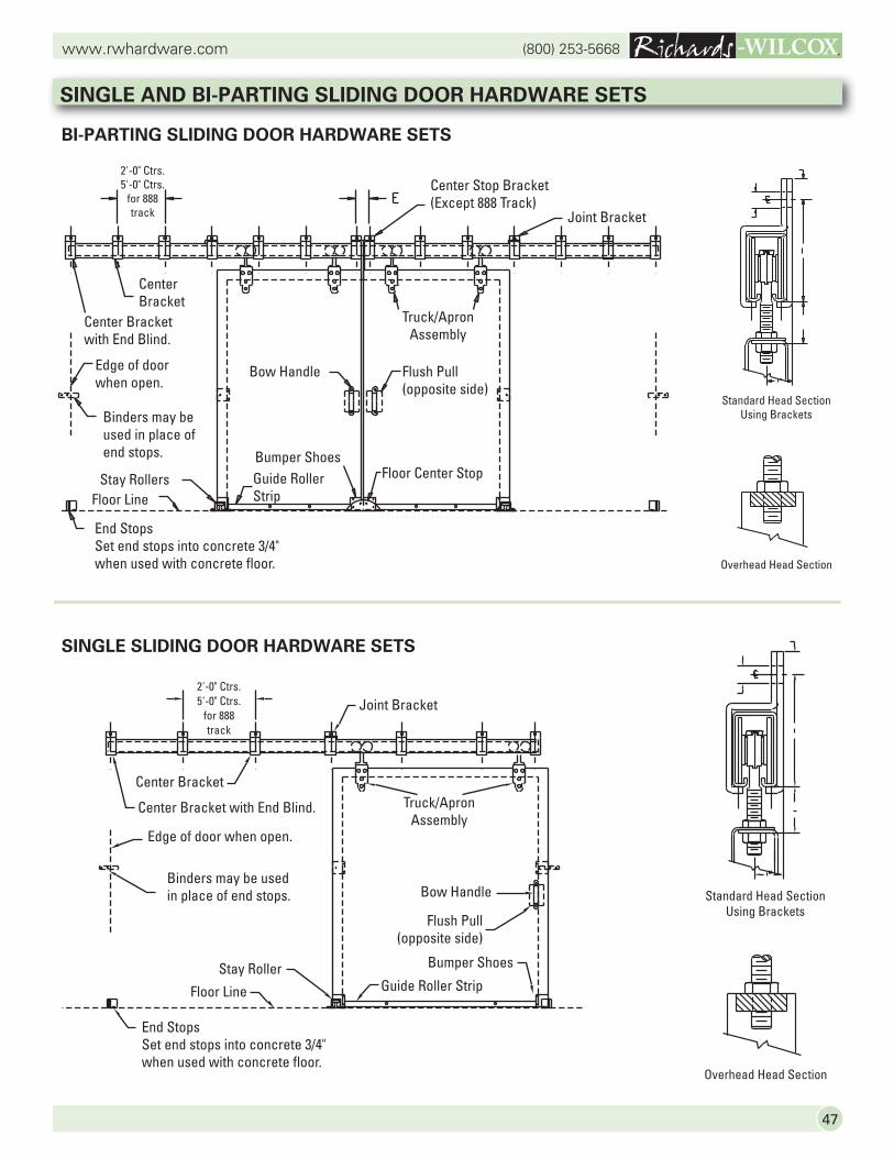
End StopsSet end stops into concrete 3/4" when used with concrete floor.
Floor Line
Stay Roller
Binders may be used in place of end stops.
Center Bracket
Center Bracket with End Blind.
Edge of door when open.
2'-0" Ctrs.5'-0" Ctrs.
for 888track
Joint Bracket
Truck/ApronAssembly
Bow Handle
Flush Pull(opposite side)
Bumper Shoes
Guide Roller Strip
SINGLE SLIDING DOOR HARDWARE SETS
Standard Head SectionUsing Brackets
End StopsSet end stops into concrete 3/4" when used with concrete floor.
Floor LineStay Rollers
Binders may be used in place of end stops.
Center Bracket
Center Bracket with End Blind.
Edge of door when open.
2'-0" Ctrs.5'-0" Ctrs.
for 888track Joint Bracket
Truck/ApronAssembly
Bow Handle Flush Pull(opposite side)
Bumper ShoesGuide Roller Strip
Floor Center Stop
Center Stop Bracket(Except 888 Track)
Standard Head SectionUsing Brackets
Overhead Head Section
Overhead Head Section
BI-PARTING SLIDING DOOR HARDWARE SETS
SINGLE AND BI-PARTING SLIDING DOOR HARDWARE SETS
(800) 253-5668www.rwhardware.com
48
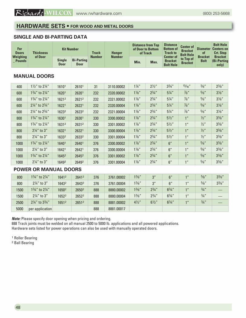
MANUAL DOORS
400 12” to 24” 16101 26101 31 3110.00002 14” 22” 3w” m” a” 2a”
600 1w” to 24” 16201 26201 232 2320.00002 18” 2w” 54” d” s” 38”
600 1w” to 24” 16212 26212 232 2321.00002 18” 2w” 54” d” s” 38”
600 24” to 2w” 16221 26221 232 2320.00004 18” 2w” 54” d” s” 38”
600 24” to 2w” 16232 26232 232 2321.00004 18” 2w” 54” d” s” 38”
800 1w” to 24” 16301 26301 330 3300.00002 18” 2w” 52” 1” 2” 3a”
800 1w” to 24” 16312 26312 330 3301.00002 18” 2w” 52” 1” 2” 3a”
800 24” to 3” 16321 26321 330 3300.00004 18” 2w” 52” 1” 2” 3a”
800 24” to 3” 16332 26332 330 3301.00004 18” 2w” 52” 1” 2” 3a”
1000 1w” to 24” 16401 26401 376 3300.00002 18” 2w” 6” 1” s” 3a”
1000 24” to 3” 16421 26421 376 3300.00004 18” 2w” 6” 1” s” 3a”
1000 1w” to 24” 16452 26452 376 3301.00002 18” 2w” 6” 1” s” 3a”
1000 24” to 3” 16492 26492 376 3301.00004 18” 2w” 6” 1” s” 3a”
Note: Please specify door opening when pricing and ordering.888 Track joints must be welded on all manual 2500 to 5000 lb. applications and all powered applications.Hardware sets listed for power operations can also be used with manually operated doors.
1 Roller Bearing2 Ball Bearing
SINGLE AND BI-PARTING DATA
POWER OR MANUAL DOORS
HARDWARE SETS • FOR WOOD AND METAL DOORS
For Doors
Weighing _ Pounds
Thickness of Door
Kit Number Track
NumberHanger Number
Distance from Top of Door to Bottom
of Track
Distance Bottom of Track to Center of Bracket
Bolt Hole
Center of Bracket
Bolt Hole to Top of Bracket
Diameter of
Bracket Bolt
Bolt Hole Centers on Crt. Stop Bracket
(Bi-Parting only)
Single Door
Bi-Parting Door Min. Max.
800 1w” to 24” 16412 26412 376 3761.00002 1a” 3” 6” 1” s” 3a”
800 24” to 3” 16432 26432 376 3761.00004 1a” 3” 6” 1” s” 3a”
1500 1w” to 24” 16502 26502 888 8880.00002 1a” 2w” 6w” 1” w” —
1500 24” to 3” 16522 26522 888 8880.00004 1a” 2w” 6w” 1” w” —
2500 24” to 3w” 16512 26512 888 8881.00002 42” 62” 6w” 1” w” —
5000 per application 888 8881.00017
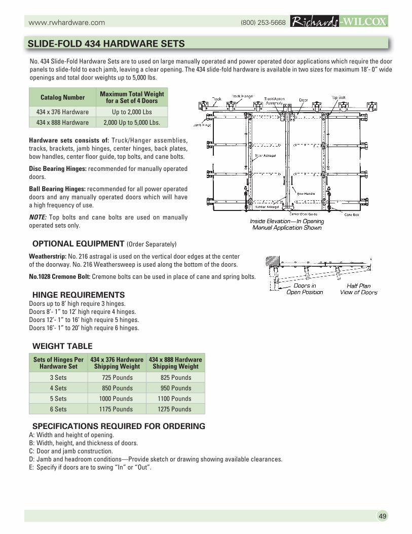
49
(800) 253-5668www.rwhardware.com
No. 434 Slide-Fold Hardware Sets are to used on large manually operated and power operated door applications which require the door panels to slide-fold to each jamb, leaving a clear opening. The 434 slide-fold hardware is available in two sizes for maximum 18’- 0” wide openings and total door weights up to 5,000 lbs.
SLIDE-FOLD 434 HARDWARE SETS
Hardware sets consists of: Truck/Hanger assemblies, tracks, brackets, jamb hinges, center hinges, back plates, bow handles, center floor guide, top bolts, and cane bolts.
Disc Bearing Hinges: recommended for manually operated doors.
Ball Bearing Hinges: recommended for all power operated doors and any manually operated doors which will have a high frequency of use.
NOTE: Top bolts and cane bolts are used on manually operated sets only.
OPTIONAL EQUIPMENT (Order Separately)
Weatherstrip: No. 216 astragal is used on the vertical door edges at the center of the doorway. No. 216 Weathersweep is used along the bottom of the doors.
No.1028 Cremone Bolt: Cremone bolts can be used in place of cane and spring bolts.
HINGE REQUIREMENTSDoors up to 8’ high require 3 hinges.Doors 8’- 1” to 12’ high require 4 hinges.Doors 12’- 1” to 16’ high require 5 hinges.Doors 16’- 1” to 20’ high require 6 hinges.
WEIGHT TABLE
SPECIFICATIONS REQUIRED FOR ORDERINGA: Width and height of opening.B: Width, height, and thickness of doors.C: Door and jamb construction.D: Jamb and headroom conditions—Provide sketch or drawing showing available clearances.E: Specify if doors are to swing “In” or “Out”.
Sets of Hinges Per Hardware Set
434 x 376 Hardware Shipping Weight
434 x 888 Hardware Shipping Weight
3 Sets 725 Pounds 825 Pounds
4 Sets 850 Pounds 950 Pounds
5 Sets 1000 Pounds 1100 Pounds
6 Sets 1175 Pounds 1275 Pounds
Catalog Number Maximum Total Weight for a Set of 4 Doors
434 x 376 Hardware Up to 2,000 Lbs
434 x 888 Hardware 2,000 Up to 5,000 Lbs.
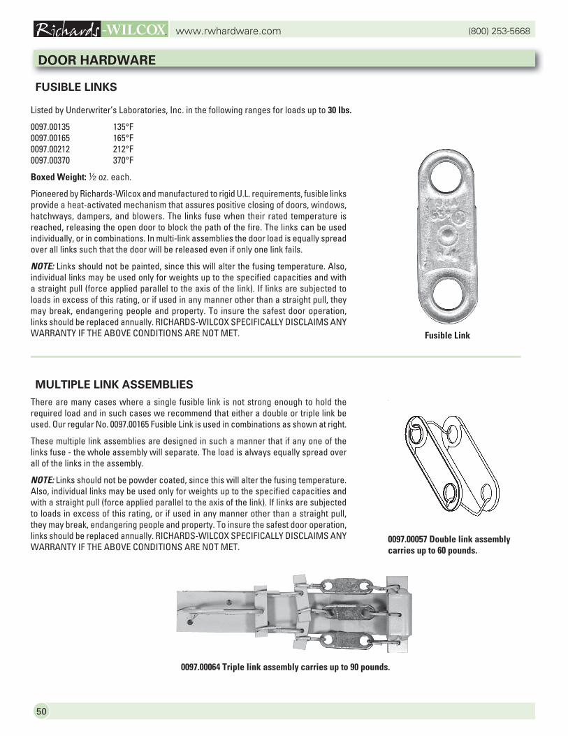
(800) 253-5668www.rwhardware.com
50
FUSIBLE LINKS
Listed by Underwriter’s Laboratories, Inc. in the following ranges for loads up to 30 lbs.
0097.00135 135°F0097.00165 165°F0097.00212 212°F0097.00370 370°F
Boxed Weight: 2 oz. each.
Pioneered by Richards-Wilcox and manufactured to rigid U.L. requirements, fusible links provide a heat-activated mechanism that assures positive closing of doors, windows, hatchways, dampers, and blowers. The links fuse when their rated temperature is reached, releasing the open door to block the path of the fire. The links can be used individually, or in combinations. In multi-link assemblies the door load is equally spread over all links such that the door will be released even if only one link fails.
NOTE: Links should not be painted, since this will alter the fusing temperature. Also, individual links may be used only for weights up to the specified capacities and with a straight pull (force applied parallel to the axis of the link). If links are subjected to loads in excess of this rating, or if used in any manner other than a straight pull, they may break, endangering people and property. To insure the safest door operation, links should be replaced annually. RICHARDS-WILCOX SPECIFICALLY DISCLAIMS ANY WARRANTY IF THE ABOVE CONDITIONS ARE NOT MET.
MULTIPLE LINK ASSEMBLIES
There are many cases where a single fusible link is not strong enough to hold the required load and in such cases we recommend that either a double or triple link be used. Our regular No. 0097.00165 Fusible Link is used in combinations as shown at right.
These multiple link assemblies are designed in such a manner that if any one of the links fuse - the whole assembly will separate. The load is always equally spread over all of the links in the assembly.
NOTE: Links should not be powder coated, since this will alter the fusing temperature. Also, individual links may be used only for weights up to the specified capacities and with a straight pull (force applied parallel to the axis of the link). If links are subjected to loads in excess of this rating, or if used in any manner other than a straight pull, they may break, endangering people and property. To insure the safest door operation, links should be replaced annually. RICHARDS-WILCOX SPECIFICALLY DISCLAIMS ANY WARRANTY IF THE ABOVE CONDITIONS ARE NOT MET.
0097.00057 Double link assembly carries up to 60 pounds.
0097.00064 Triple link assembly carries up to 90 pounds.
DOOR HARDWARE
Fusible Link
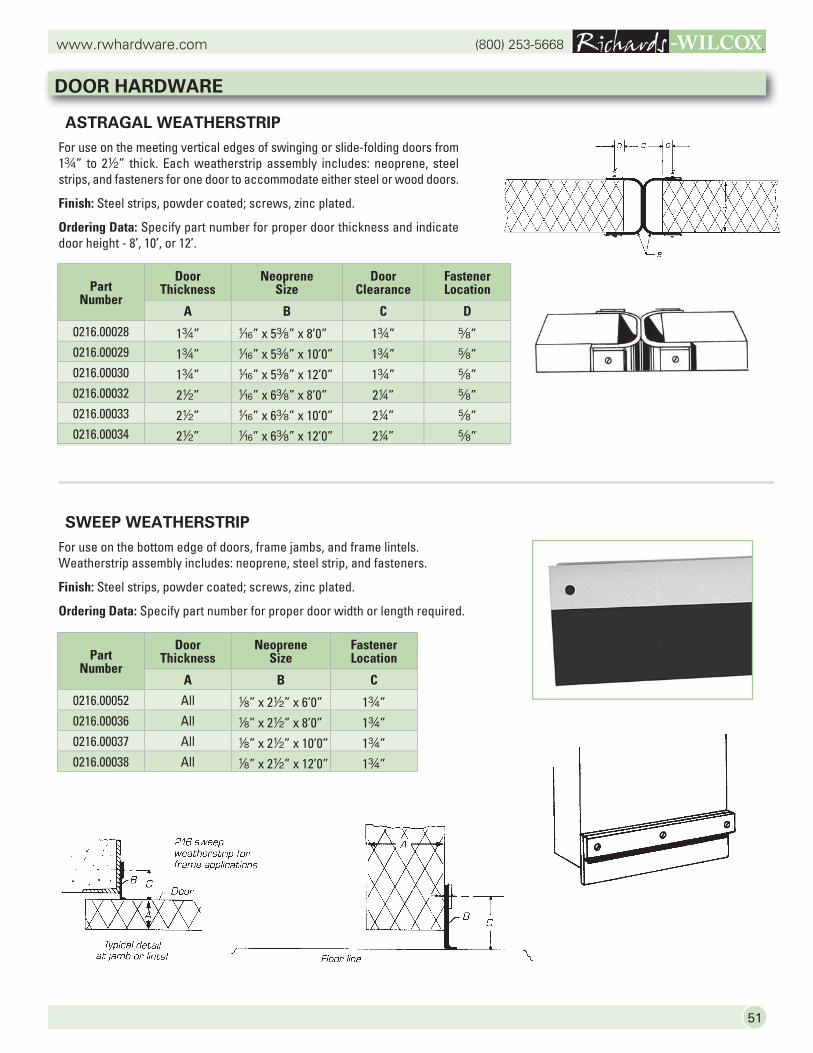
51
(800) 253-5668www.rwhardware.com
ASTRAGAL WEATHERSTRIP
For use on the meeting vertical edges of swinging or slide-folding doors from 1w” to 22” thick. Each weatherstrip assembly includes: neoprene, steel strips, and fasteners for one door to accommodate either steel or wood doors.
Finish: Steel strips, powder coated; screws, zinc plated.
Ordering Data: Specify part number for proper door thickness and indicate door height - 8’, 10’, or 12’.
SWEEP WEATHERSTRIP
For use on the bottom edge of doors, frame jambs, and frame lintels. Weatherstrip assembly includes: neoprene, steel strip, and fasteners.
Finish: Steel strips, powder coated; screws, zinc plated.
Ordering Data: Specify part number for proper door width or length required.
DOOR HARDWARE
Part Number
Door Thickness
Neoprene Size
Door Clearance
Fastener Location
A B C D
0216.00028 1w” z” x 5a” x 8’0” 1w” s”0216.00029 1w” z” x 5a” x 10’0” 1w” s”0216.00030 1w” z” x 5a” x 12’0” 1w” s”0216.00032 22” z” x 6a” x 8’0” 24” s”0216.00033 22” z” x 6a” x 10’0” 24” s”0216.00034 22” z” x 6a” x 12’0” 24” s”
Part Number
Door Thickness
Neoprene Size
Fastener Location
A B C
0216.00052 All 8” x 22” x 6’0” 1w”0216.00036 All 8” x 22” x 8’0” 1w”0216.00037 All 8” x 22” x 10’0” 1w”0216.00038 All 8” x 22” x 12’0” 1w”
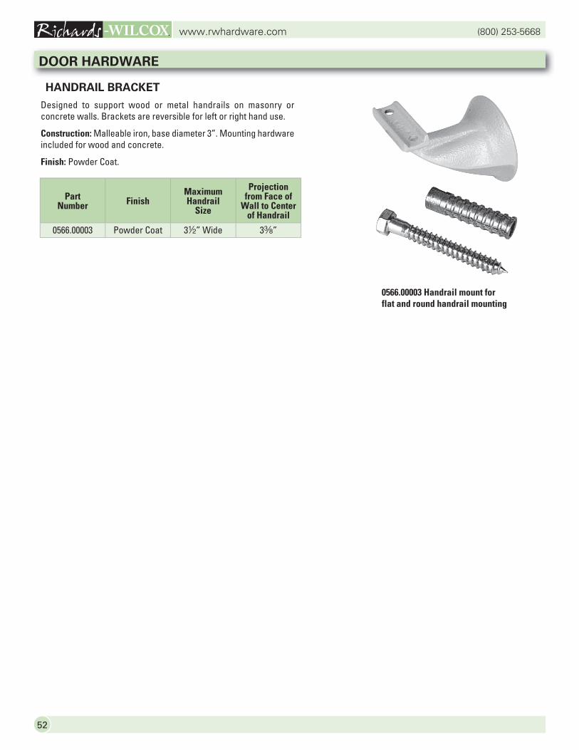
(800) 253-5668www.rwhardware.com
52
HANDRAIL BRACKET
Designed to support wood or metal handrails on masonry or concrete walls. Brackets are reversible for left or right hand use.
Construction: Malleable iron, base diameter 3”. Mounting hardware included for wood and concrete.
Finish: Powder Coat.
0566.00003 Handrail mount for flat and round handrail mounting
DOOR HARDWARE
Part Number Finish
Maximum Handrail
Size
Projection from Face of
Wall to Center of Handrail
0566.00003 Powder Coat 32” Wide 3a”
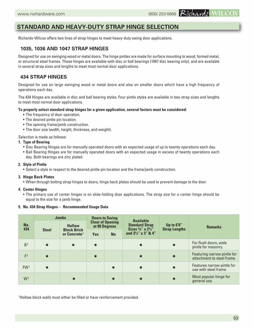
53
(800) 253-5668www.rwhardware.com
STANDARD AND HEAVY-DUTY STRAP HINGE SELECTION
1Hollow block walls must either be filled or have reinforcement provided.
No. 434
Jambs Doors to SwingClear of Opening
at 90 DegreesAvailable
Standard Strap Sizes 3/8” x 21/2”
and 31/2” x 3” & 4”
Up to 6’0”Strap Lengths Remarks
SteelHollow
Block Brick or Concrete1 Yes No
B1 ✸ ✸ ✸ ✸ ✸For flush doors, wide pintle for masonry.
F1 ✸ ✸ ✸ ✸Featuring narrow pintle for attachment to steel frame.
FW1 ✸ ✸ ✸ ✸Features narrow pintle for use with steel frame.
W1 ✸ ✸ ✸ ✸Most popular hinge for general use.
Richards-Wilcox offers two lines of strap hinges to meet heavy-duty swing door applications.
1035, 1036 AND 1047 STRAP HINGES
Designed for use on swinging wood or metal doors. The hinge pintles are made for surface mounting to wood, formed metal, or structural steel frames. These hinges are available with disc or ball bearings (1047 disc bearing only), and are available in several strap sizes and lengths to meet most normal door applications.
434 STRAP HINGES
Designed for use on large swinging wood or metal doors and also on smaller doors which have a high frequency of operations each day.
The 434 Hinges are available in disc and ball bearing styles. Four pintle styles are available in two strap sizes and lengths to meet most normal door applications.
To properly select standard strap hinges for a given application, several factors must be considered: • The frequency of door operation. • The desired pintle pin location. • The opening frame/jamb construction. • The door size (width, height, thickness, and weight).
Selection is made as follows:1. Type of Bearing • Disc Bearing Hinges are for manually operated doors with an expected usage of up to twenty operations each day. • Ball Bearing Hinges are for manually operated doors with an expected usage in excess of twenty operations each day. Both bearings are zinc plated.
2. Style of Pintle • Select a style in respect to the desired pintle pin location and the frame/jamb construction.
3. Hinge Back Plates • When through bolting strap hinges to doors, hinge back plates should be used to prevent damage to the door.
4. Center Hinges • The primary use of center hinges is on slide-folding door applications. The strap size for a center hinge should be equal to the size for a jamb hinge.
5. No. 434 Strap Hinges – Recommended Usage Data
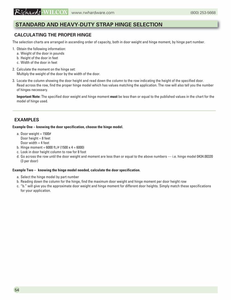
(800) 253-5668www.rwhardware.com
54
CALCULATING THE PROPER HINGE
The selection charts are arranged in ascending order of capacity, both in door weight and hinge moment, by hinge part number.
1. Obtain the following information: a. Weight of the door in pounds b. Height of the door in feet c. Width of the door in feet
2. Calculate the moment on the hinge set: Multiply the weight of the door by the width of the door.
3. Locate the column showing the door height and read down the column to the row indicating the height of the specified door. Read across the row, find the proper hinge model which has values matching the application. The row will also tell you the number of hinges necessary.
Important Note: The specified door weight and hinge moment must be less than or equal to the published values in the chart for the model of hinge used.
EXAMPLES
Example One – knowing the door specification, choose the hinge model.
a. Door weight = 1500# Door height = 8 feet Door width = 4 feet b. Hinge moment = 6000 ft./# (1500 x 4 = 6000) c. Look in door height column to row for 8 foot d. Go across the row until the door weight and moment are less than or equal to the above numbers — i.e. hinge model 0434.00320
(3 per door)
Example Two – knowing the hinge model needed, calculate the door specification.
a. Select the hinge model by part number b. Reading down the column for the hinge, find the maximum door weight and hinge moment per door height row c. “b.” will give you the approximate door weight and hinge moment for different door heights. Simply match these specifications
for your application.
STANDARD AND HEAVY-DUTY STRAP HINGE SELECTION
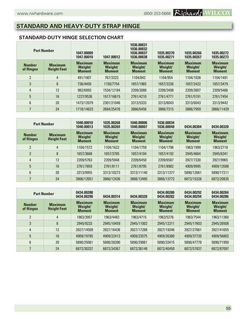
55
(800) 253-5668www.rwhardware.com
Part Number 1040.000101040.00013
1035.002681035.00269
1040.000061040.00007
1036.000341036.00040 0434.00304 0434.00320
Number of Hinges
Maximum Height Feet
Maximum Weight/Moment
Maximum Weight/Moment
Maximum Weight/Moment
Maximum Weight/Moment
Maximum Weight/Moment
Maximum Weight/Moment
2 4 1104/1572 1104/1622 1104/1759 1104/1796 1963/1999 1963/2718
3 8 1657/3668 1657/3785 1657/4104 1657/4192 2945/4664 2945/6341
4 12 2209/5763 2209/5948 2209/6450 2209/6587 3927/7330 3927/9965
5 16 2761/7859 2761/8111 2761/8795 2761/8982 4909/9995 4909/13588
6 20 3313/9955 3313/10273 3313/11140 3313/11377 5890/12661 5890/17211
7 24 3866/12051 3866/12436 3866/13485 3866/13772 6872/15326 6872/20835
Part Number 0434.002880434.00290 0434.00314 0434.00328
0434.002800434.00282
0434.002920434.00294
0434.002840434.00286
Number of Hinges
Maximum Height Feet
Maximum Weight/Moment
Maximum Weight/Moment
Maximum Weight/Moment
Maximum Weight/Moment
Maximum Weight/Moment
Maximum Weight/Moment
2 4 1963/3957 1963/4483 1963/4715 1963/5276 1963/7544 1963/11360
3 8 2945/9233 2945/10459 2945/11002 2945/12311 2945/17603 2945/26508
4 12 3927/14509 3927/16436 3927/17288 3927/19346 3927/27661 3927/41655
5 16 4909/19785 4909/22413 4909/23575 4909/26380 4909/37720 4909/56802
6 20 5890/25061 5890/28390 5890/29861 5890/33415 5890/47778 5890/71950
7 24 6872/30337 6872/34367 6872/36148 6872/40450 6872/57837 6872/87097
Part Number 1047.000091047.00010 1047.00012
1036.000311036.000321036.000371036.00038
1035.002701035.00271
1035.002661035.00267
1035.002721035.00273
Number of Hinges
Maximum Height Feet
Maximum Weight/Moment
Maximum Weight/Moment
Maximum Weight/Moment
Maximum Weight/Moment
Maximum Weight/Moment
Maximum Weight/Moment
2 4 491/1907 767/3323 1104/842 1104/954 1104/1038 1104/1491
3 8 736/4450 1150/7754 1657/1965 1657/2226 1657/2422 1657/3479
4 12 982/6993 1534/12184 2209/3088 2209/3498 2209/3807 2209/5466
5 16 1227/9536 1917/16615 2761/4210 2761/4771 2761/5191 2761/7454
6 20 1473/12079 2301/21046 3313/5333 3313/6043 3313/6043 3313/9442
7 24 1718/14623 2684/25476 3866/6456 3866/7315 3866/7959 3866/11429
STANDARD AND HEAVY-DUTY STRAP HINGE
STANDARD-DUTY HINGE SELECTION CHART
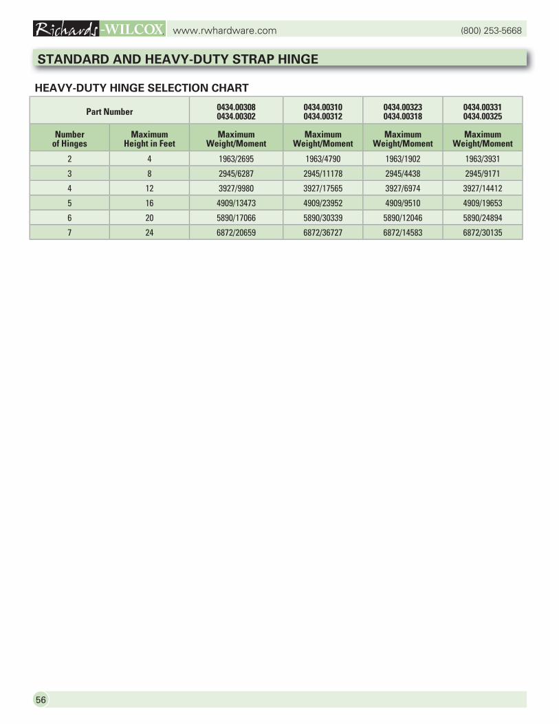
(800) 253-5668www.rwhardware.com
56
HEAVY-DUTY HINGE SELECTION CHART
STANDARD AND HEAVY-DUTY STRAP HINGE
Part Number 0434.003080434.00302
0434.003100434.00312
0434.003230434.00318
0434.003310434.00325
Numberof Hinges
MaximumHeight in Feet
MaximumWeight/Moment
MaximumWeight/Moment
MaximumWeight/Moment
MaximumWeight/Moment
2 4 1963/2695 1963/4790 1963/1902 1963/3931
3 8 2945/6287 2945/11178 2945/4438 2945/9171
4 12 3927/9980 3927/17565 3927/6974 3927/14412
5 16 4909/13473 4909/23952 4909/9510 4909/19653
6 20 5890/17066 5890/30339 5890/12046 5890/24894
7 24 6872/20659 6872/36727 6872/14583 6872/30135
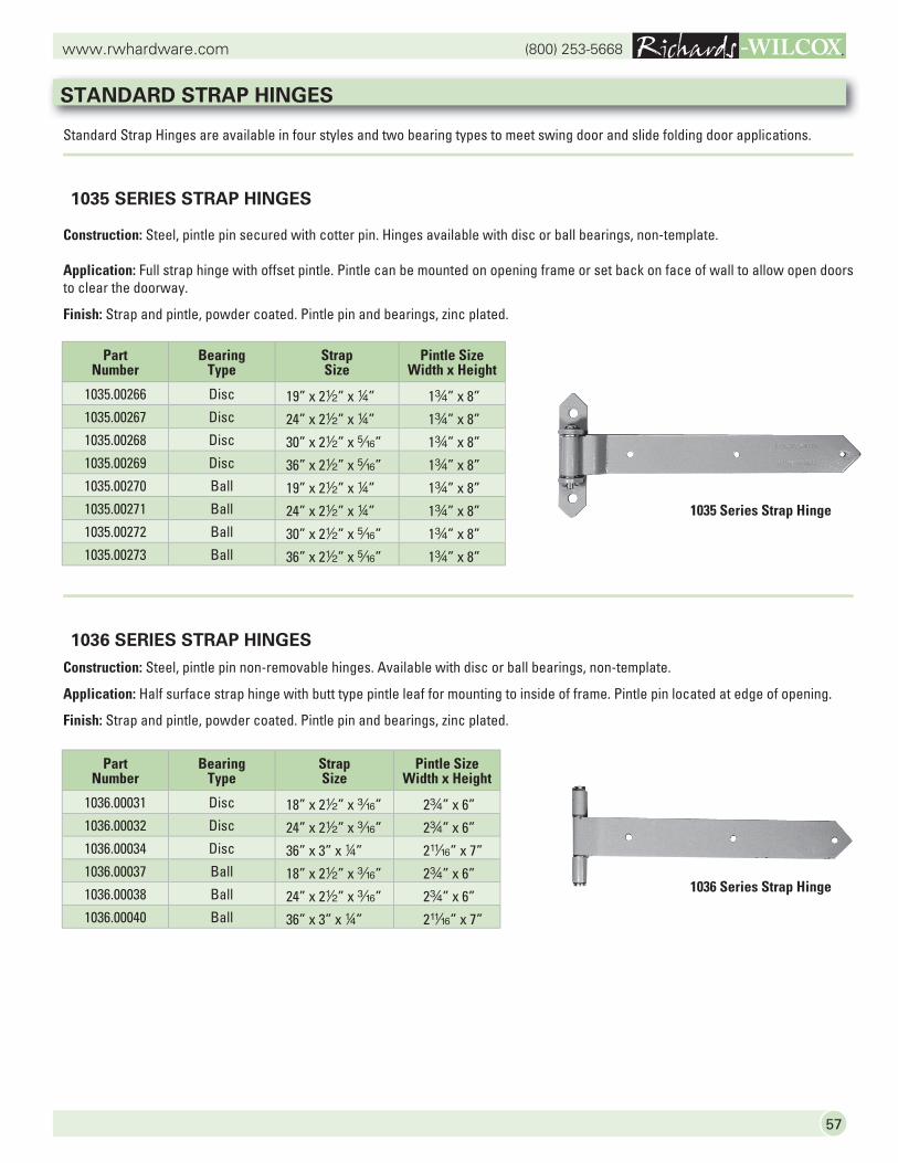
57
(800) 253-5668www.rwhardware.com
Standard Strap Hinges are available in four styles and two bearing types to meet swing door and slide folding door applications.
1035 SERIES STRAP HINGES
Construction: Steel, pintle pin secured with cotter pin. Hinges available with disc or ball bearings, non-template.
Application: Full strap hinge with offset pintle. Pintle can be mounted on opening frame or set back on face of wall to allow open doors to clear the doorway.
Finish: Strap and pintle, powder coated. Pintle pin and bearings, zinc plated.
1036 SERIES STRAP HINGES
Construction: Steel, pintle pin non-removable hinges. Available with disc or ball bearings, non-template.
Application: Half surface strap hinge with butt type pintle leaf for mounting to inside of frame. Pintle pin located at edge of opening.
Finish: Strap and pintle, powder coated. Pintle pin and bearings, zinc plated.
Part Number
Bearing Type
Strap Size
Pintle Size Width x Height
1035.00266 Disc 19” x 22” x 4” 1w” x 8”1035.00267 Disc 24” x 22” x 4” 1w” x 8”1035.00268 Disc 30” x 22” x c” 1w” x 8”1035.00269 Disc 36” x 22” x c” 1w” x 8”1035.00270 Ball 19” x 22” x 4” 1w” x 8”1035.00271 Ball 24” x 22” x 4” 1w” x 8”1035.00272 Ball 30” x 22” x c” 1w” x 8”1035.00273 Ball 36” x 22” x c” 1w” x 8”
Part Number
Bearing Type
Strap Size
Pintle Size Width x Height
1036.00031 Disc 18” x 22” x x” 2w” x 6”1036.00032 Disc 24” x 22” x x” 2w” x 6”1036.00034 Disc 36” x 3” x 4” 2n” x 7”1036.00037 Ball 18” x 22” x x” 2w” x 6”1036.00038 Ball 24” x 22” x x” 2w” x 6”1036.00040 Ball 36” x 3” x 4” 2n” x 7”
1036 Series Strap Hinge
STANDARD STRAP HINGES
1035 Series Strap Hinge
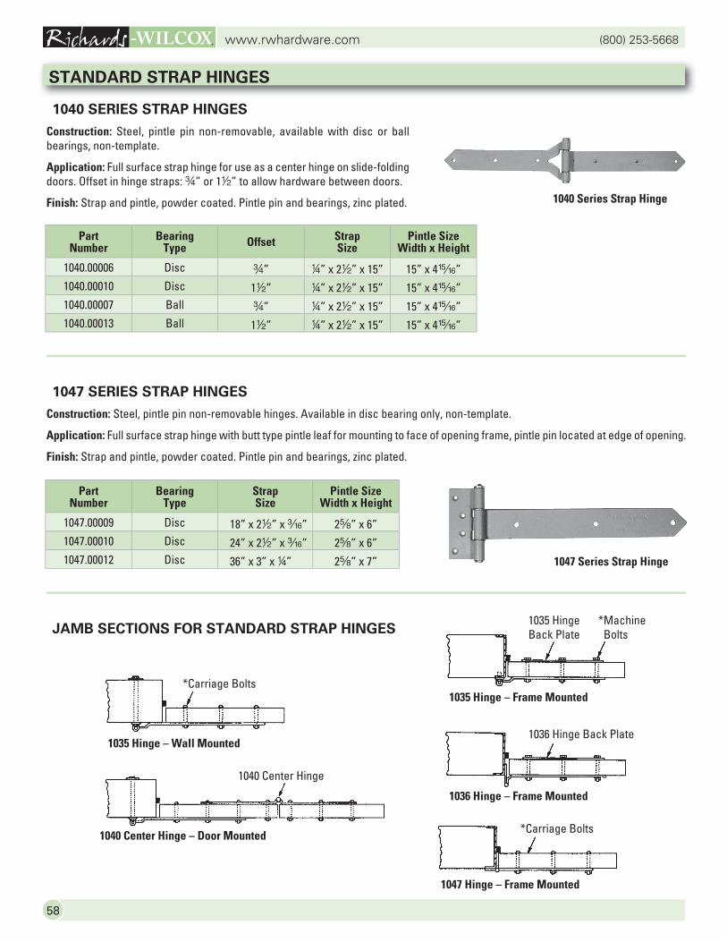
(800) 253-5668www.rwhardware.com
58
JAMB SECTIONS FOR STANDARD STRAP HINGES
1040 SERIES STRAP HINGES
Construction: Steel, pintle pin non-removable, available with disc or ball bearings, non-template.
Application: Full surface strap hinge for use as a center hinge on slide-folding doors. Offset in hinge straps: w” or 12” to allow hardware between doors.
Finish: Strap and pintle, powder coated. Pintle pin and bearings, zinc plated.
1047 SERIES STRAP HINGES
Construction: Steel, pintle pin non-removable hinges. Available in disc bearing only, non-template.
Application: Full surface strap hinge with butt type pintle leaf for mounting to face of opening frame, pintle pin located at edge of opening.
Finish: Strap and pintle, powder coated. Pintle pin and bearings, zinc plated.
*Machine Bolts
1035 Hinge – Frame Mounted
1036 Hinge Back Plate
1036 Hinge – Frame Mounted
*Carriage Bolts
1035 Hinge – Wall Mounted
*Carriage Bolts
1047 Hinge – Frame Mounted
1040 Center Hinge – Door Mounted
1040 Center Hinge
Part Number
Bearing Type
Strap Size
Pintle Size Width x Height
1047.00009 Disc 18” x 22” x x” 2s” x 6”1047.00010 Disc 24” x 22” x x” 2s” x 6”1047.00012 Disc 36” x 3” x 4” 2s” x 7”
STANDARD STRAP HINGES
1040 Series Strap Hinge
1047 Series Strap Hinge
Part Number
Bearing Type Offset Strap
SizePintle Size
Width x Height
1040.00006 Disc w” 4” x 22” x 15” 15” x 4,”1040.00010 Disc 12” 4” x 22” x 15” 15” x 4,”1040.00007 Ball w” 4” x 22” x 15” 15” x 4,”1040.00013 Ball 12” 4” x 22” x 15” 15” x 4,”
1035 Hinge Back Plate
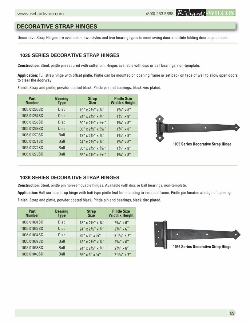
59
(800) 253-5668www.rwhardware.com
1036 SERIES DECORATIVE STRAP HINGES
Construction: Steel, pintle pin non-removable hinges. Available with disc or ball bearings, non-template.
Application: Half surface strap hinge with butt type pintle leaf for mounting to inside of frame. Pintle pin located at edge of opening.
Finish: Strap and pintle, powder coated black. Pintle pin and bearings, black zinc plated.
Decorative Strap Hinges are available in two styles and two bearing types to meet swing door and slide folding door applications.
1035 SERIES DECORATIVE STRAP HINGES
Construction: Steel, pintle pin secured with cotter pin. Hinges available with disc or ball bearings, non-template.
Application: Full strap hinge with offset pintle. Pintle can be mounted on opening frame or set back on face of wall to allow open doors to clear the doorway.
Finish: Strap and pintle, powder coated black. Pintle pin and bearings, black zinc plated..
1035 Series Decorative Strap Hinge
Part Number
Bearing Type
Strap Size
Pintle Size Width x Height
1035.01266SC Disc 19” x 22” x 4” 1w” x 8”1035.01267SC Disc 24” x 22” x 4” 1w” x 8”1035.01268SC Disc 30” x 22” x c” 1w” x 8”1035.01269SC Disc 36” x 22” x c” 1w” x 8”1035.01270SC Ball 19” x 22” x 4” 1w” x 8”1035.01271SC Ball 24” x 22” x 4” 1w” x 8”1035.01272SC Ball 30” x 22” x c” 1w” x 8”1035.01273SC Ball 36” x 22” x c” 1w” x 8”
Part Number
Bearing Type
Strap Size
Pintle Size Width x Height
1036.01031SC Disc 18” x 22” x 4” 2w” x 6”1036.01032SC Disc 24” x 22” x 4” 2w” x 6”1036.01034SC Disc 36” x 3” x 4” 2n” x 7”1036.01037SC Ball 18” x 22” x 4” 2w” x 6”1036.01038SC Ball 24” x 22” x 4” 2w” x 6”1036.01040SC Ball 36” x 3” x 4” 2n” x 7”
DECORATIVE STRAP HINGES
1036 Series Decorative Strap Hinge
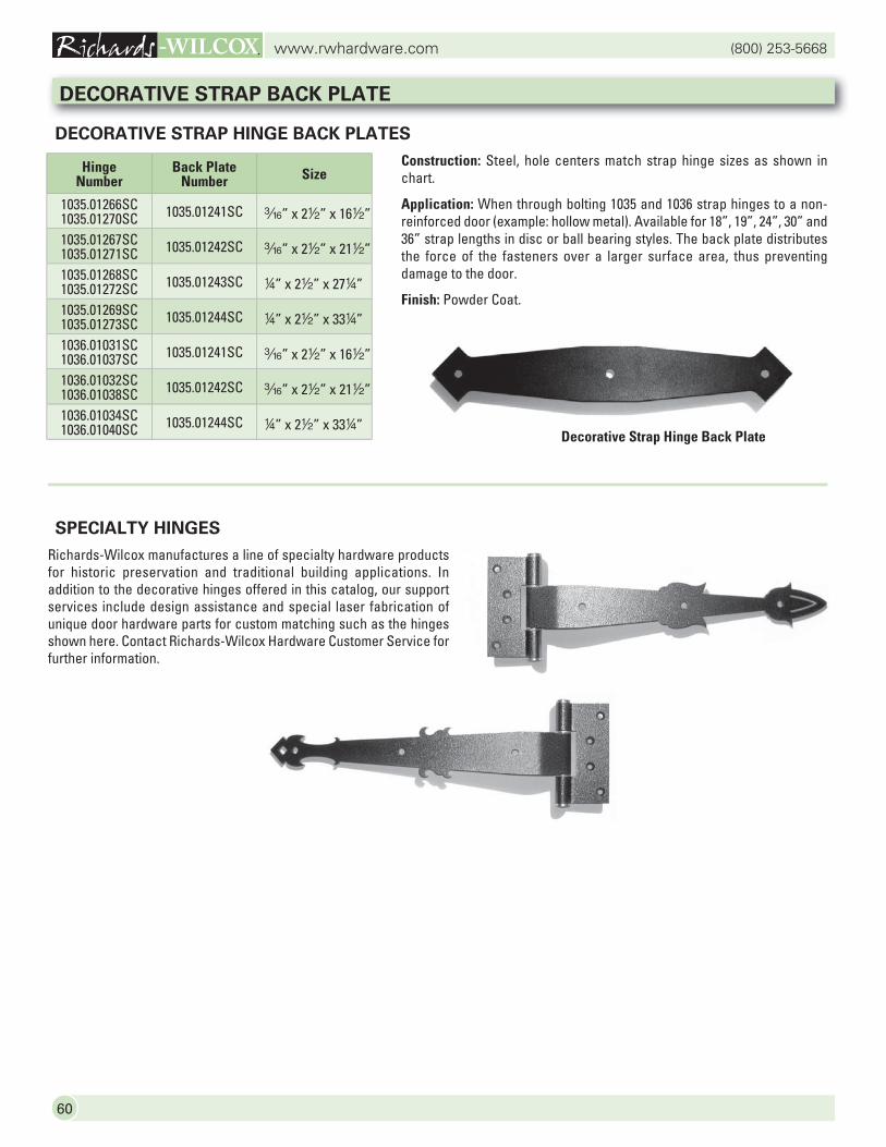
(800) 253-5668www.rwhardware.com
60
DECORATIVE STRAP BACK PLATE
DECORATIVE STRAP HINGE BACK PLATES
Construction: Steel, hole centers match strap hinge sizes as shown in chart.
Application: When through bolting 1035 and 1036 strap hinges to a non-reinforced door (example: hollow metal). Available for 18”, 19”, 24”, 30” and 36” strap lengths in disc or ball bearing styles. The back plate distributes the force of the fasteners over a larger surface area, thus preventing damage to the door.
Finish: Powder Coat.
SPECIALTY HINGES
Richards-Wilcox manufactures a line of specialty hardware products for historic preservation and traditional building applications. In addition to the decorative hinges offered in this catalog, our support services include design assistance and special laser fabrication of unique door hardware parts for custom matching such as the hinges shown here. Contact Richards-Wilcox Hardware Customer Service for further information.
Decorative Strap Hinge Back Plate
Hinge Number
Back Plate Number Size
1035.01266SC1035.01270SC 1035.01241SC x” x 22” x 162”
1035.01267SC1035.01271SC 1035.01242SC x” x 22” x 212”
1035.01268SC1035.01272SC 1035.01243SC 4” x 22” x 274”
1035.01269SC1035.01273SC 1035.01244SC 4” x 22” x 334”
1036.01031SC1036.01037SC 1035.01241SC x” x 22” x 162”
1036.01032SC1036.01038SC 1035.01242SC x” x 22” x 212”
1036.01034SC1036.01040SC 1035.01244SC 4” x 22” x 334”
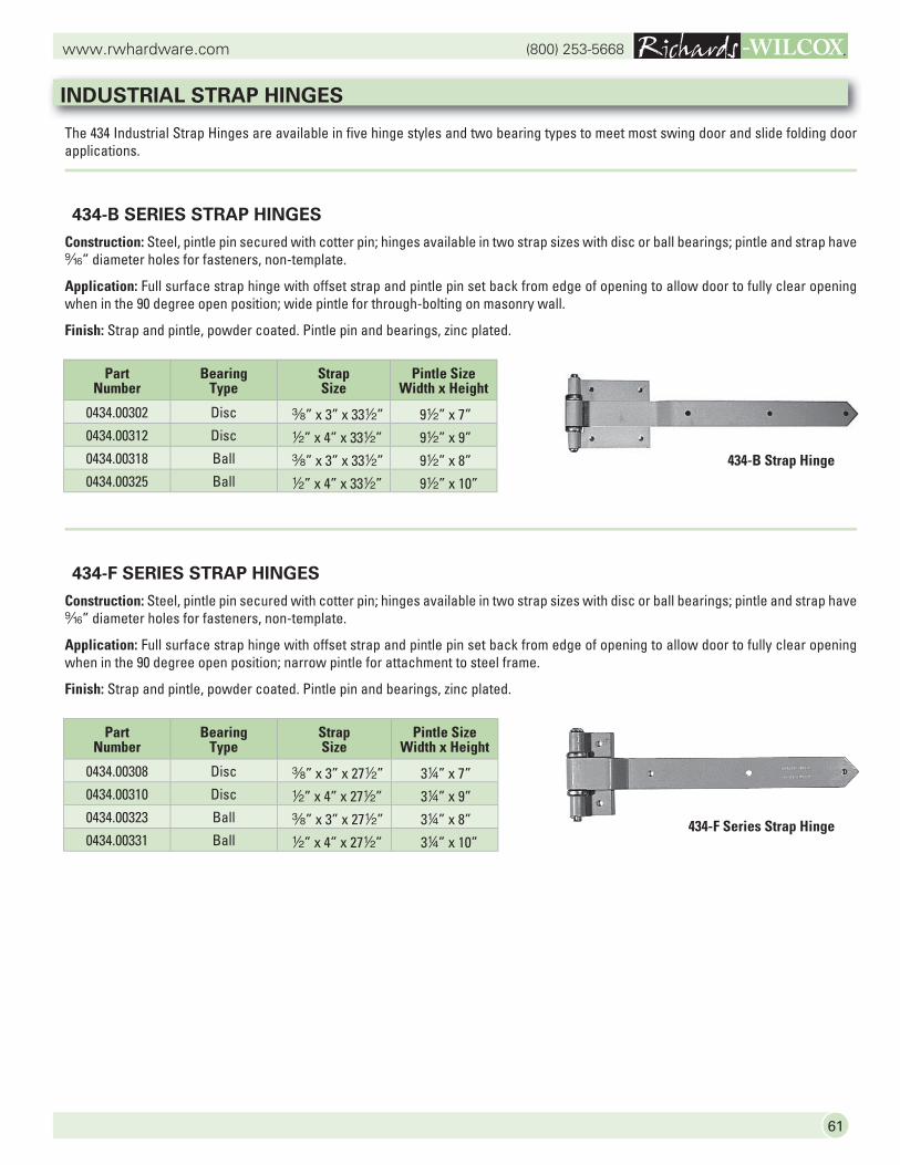
61
(800) 253-5668www.rwhardware.com
The 434 Industrial Strap Hinges are available in five hinge styles and two bearing types to meet most swing door and slide folding door applications.
434-B SERIES STRAP HINGES
Construction: Steel, pintle pin secured with cotter pin; hinges available in two strap sizes with disc or ball bearings; pintle and strap have b” diameter holes for fasteners, non-template.
Application: Full surface strap hinge with offset strap and pintle pin set back from edge of opening to allow door to fully clear opening when in the 90 degree open position; wide pintle for through-bolting on masonry wall.
Finish: Strap and pintle, powder coated. Pintle pin and bearings, zinc plated.
434-F SERIES STRAP HINGES
Construction: Steel, pintle pin secured with cotter pin; hinges available in two strap sizes with disc or ball bearings; pintle and strap have b” diameter holes for fasteners, non-template.
Application: Full surface strap hinge with offset strap and pintle pin set back from edge of opening to allow door to fully clear opening when in the 90 degree open position; narrow pintle for attachment to steel frame.
Finish: Strap and pintle, powder coated. Pintle pin and bearings, zinc plated.
Part Number
Bearing Type
Strap Size
Pintle Size Width x Height
0434.00302 Disc a” x 3” x 332” 92” x 7”0434.00312 Disc 2” x 4” x 332” 92” x 9”0434.00318 Ball a” x 3” x 332” 92” x 8”0434.00325 Ball 2” x 4” x 332” 92” x 10”
Part Number
Bearing Type
Strap Size
Pintle Size Width x Height
0434.00308 Disc a” x 3” x 272” 34” x 7”0434.00310 Disc 2” x 4” x 272” 34” x 9”0434.00323 Ball a” x 3” x 272” 34” x 8”0434.00331 Ball 2” x 4” x 272” 34” x 10”
434-F Series Strap Hinge
INDUSTRIAL STRAP HINGES
434-B Strap Hinge
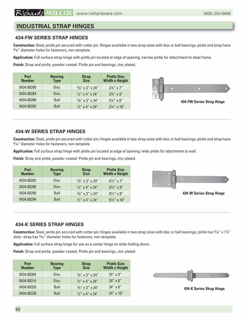
(800) 253-5668www.rwhardware.com
62
434-K SERIES STRAP HINGES
Construction: Steel, pintle pin secured with cotter pin; hinges available in two strap sizes with disc or ball bearings; pintle has b” x 14” slots- strap has b” diameter holes for fasteners, non-template.
Application: Full surface strap hinge for use as a center hinge on slide-folding doors.
Finish: Strap and pintle, powder coated. Pintle pin and bearings, zinc plated.
434-FW SERIES STRAP HINGES
Construction: Steel, pintle pin secured with cotter pin. Hinges available in two strap sizes with disc or ball bearings; pintle and strap have b” diameter holes for fasteners, non-template.
Application: Full surface strap hinge with pintle pin located at edge of opening; narrow pintle for attachment to steel frame.
Finish: Strap and pintle, powder coated. Pintle pin and bearings, zinc plated.
434-W SERIES STRAP HINGES
Construction: Steel, pintle pin secured with cotter pin; hinges available in two strap sizes with disc or ball bearings; pintle and strap have b” diameter holes for fasteners, non-template.
Application: Full surface strap hinge with pintle pin located at edge of opening; wide pintle for attachment to wall.
Finish: Strap and pintle, powder coated. Pintle pin and bearings, zinc plated.
Part Number
Bearing Type
Strap Size
Pintle Size Width x Height
0434.00280 Disc a” x 3” x 24” 34” x 7”0434.00284 Disc 2” x 4” x 24” 34” x 9”0434.00288 Ball a” x 3” x 24” 34” x 8”0434.00292 Ball 2” x 4” x 24” 34” x 10”
Part Number
Bearing Type
Strap Size
Pintle Size Width x Height
0434.00282 Disc a” x 3” x 24” 92” x 7”0434.00286 Disc 2” x 4” x 24” 92” x 9”0434.00290 Ball a” x 3” x 24” 92” x 8”0434.00294 Ball 2” x 4” x 24” 92” x 10”
Part Number
Bearing Type
Strap Size
Pintle Size Width x Height
0434.00304 Disc a” x 3” x 24” 24” x 6”
0434.00314 Disc 2” x 4” x 24” 24” x 8”
0434.00320 Ball a” x 3” x 24” 24” x 8”
0434.00328 Ball 2” x 4” x 24” 24” x 10”
INDUSTRIAL STRAP HINGES
434-FW Series Strap Hinge
434-W Series Strap Hinge
434-K Series Strap Hinge
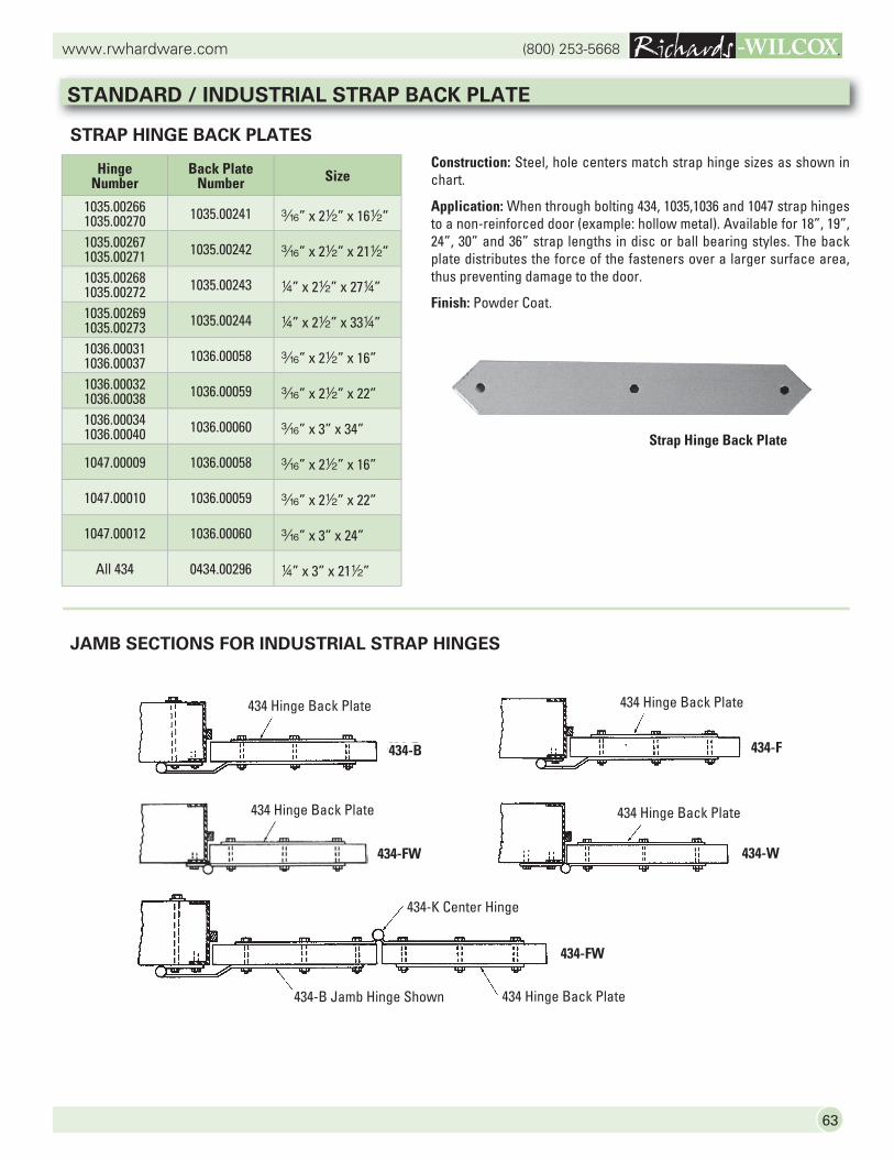
63
(800) 253-5668www.rwhardware.com
STANDARD / INDUSTRIAL STRAP BACK PLATE
STRAP HINGE BACK PLATES
Construction: Steel, hole centers match strap hinge sizes as shown in chart.
Application: When through bolting 434, 1035,1036 and 1047 strap hinges to a non-reinforced door (example: hollow metal). Available for 18”, 19”, 24”, 30” and 36” strap lengths in disc or ball bearing styles. The back plate distributes the force of the fasteners over a larger surface area, thus preventing damage to the door.
Finish: Powder Coat.
Strap Hinge Back Plate
JAMB SECTIONS FOR INDUSTRIAL STRAP HINGES
434-B434-B
434 Hinge Back Plate
434-F
434 Hinge Back Plate
434-FW
434 Hinge Back Plate
434-W
434 Hinge Back Plate
434-FW
434-K Center Hinge
434 Hinge Back Plate434-B Jamb Hinge Shown
Hinge Number
Back Plate Number Size
1035.002661035.00270 1035.00241 x” x 22” x 162”
1035.002671035.00271 1035.00242 x” x 22” x 212”
1035.002681035.00272 1035.00243 4” x 22” x 274”
1035.002691035.00273 1035.00244 4” x 22” x 334”
1036.000311036.00037 1036.00058 x” x 22” x 16”
1036.000321036.00038 1036.00059 x” x 22” x 22”
1036.000341036.00040 1036.00060 x” x 3” x 34”
1047.00009 1036.00058 x” x 22” x 16”
1047.00010 1036.00059 x” x 22” x 22”
1047.00012 1036.00060 x” x 3” x 24”
All 434 0434.00296 4” x 3” x 212”
64
(800) 253-5668www.rwhardware.com
RICHARDS-WILCOX TEN-YEAR WARRANTY
HARDWARE PRODUCTS
Richards-Wilcox Hardware Products are warranted to be of good quality, and free from defects in material and workmanship under normal intended use for a period of ten (10) years from the date of purchase. If any hardware, or part thereof, is determined by Richards-Wilcox not to be as warranted, Richards-Wilcox will at its option and without charge, replace the defective part or parts.
UNDER NO CIRCUMSTANCES SHALL WE BE LIABLE FOR INDIRECT OR CONSEQUENTIAL DAMAGES OF ANY KIND. THESE WARRANTIES ARE IN LIEU OF ALL OTHER WARRANTIES EXPRESSED OR IMPLIED INCLUDING, BUT NOT LIMITED TO, WARRANTIES OF MERCHANTABILITY OR FITNESS FOR A PARTICULAR PURPOSE. THE WARRANTIES COVER RICHARDS-WILCOX MATERIAL. WE SHALL NOT BE LIABLE, NOR DO WE ASSUME RESPONSIBILITY FOR DAMAGE OR OPERATIONAL FAILURES CAUSED BY SUPPORTING AND/OR SURROUNDING STRUCTURE AND/OR EQUIPMENT, OVERLOADING OF THE PRODUCT BEYOND THE MANUFACTURER’S RATED CAPACITY, IMPROPER USE OR APPLICATION BEYOND THE MANUFACTURER’S INTENDED OR RECOMMENDED USE, OR OTHER EXTERNAL CAUSES SUCH AS ABUSE OR ACTS OF GOD AND OTHER CAUSES BEYOND OUR CONTROL. MAINTENANCE AND ADJUSTMENTS ARE THE RESPONSIBILITY OF THE OWNER. THIS GUARANTEE DOES NOT COVER SUCH MAINTENANCE AND ADJUSTMENTS, NOR ANY SERVICES WHICH MAY BE REQUIRED AS A RESULT OF THE PURCHASER’S FAILURE TO PERFORM NORMAL MAINTENANCE AND ADJUSTMENTS TO THE PURCHASED PRODUCT.
Replacement of defective material shall be furnished without charge, delivered, installation not included. If Richards-Wilcox decides to service a warranted product at the purchaser’s place of business and determines that no defective material or improper workmanship exists, then the purchaser shall reimburse Richards-Wilcox Company for all expenses, including time and travel, incurred in providing the service.
This warranty is not applicable to other Richards-Wilcox non-hardware products.