Embed Size (px)
Citation preview
Edition 3 / Revision 13 ROADS AND MARITIME SERVICES February 2012
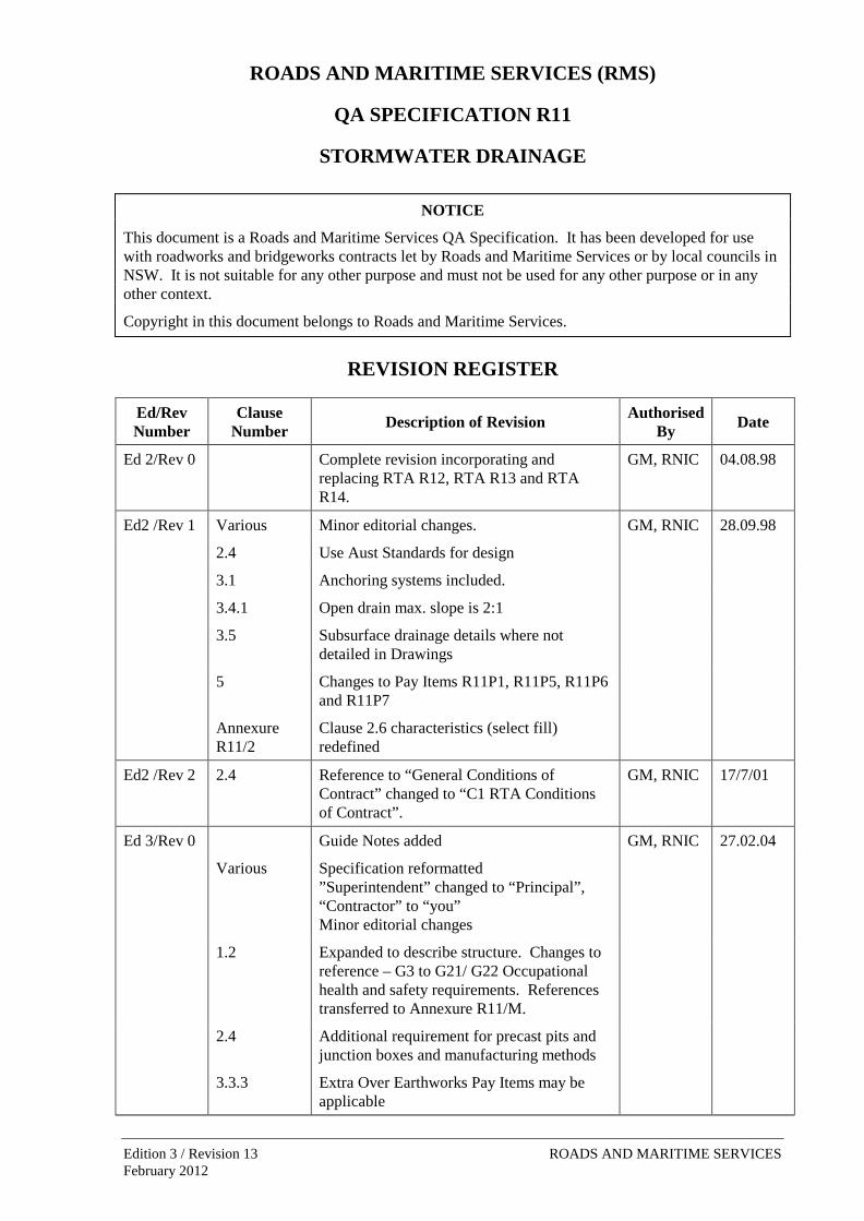
ROADS AND MARITIME SERVICES (RMS)
QA SPECIFICATION R11
STORMWATER DRAINAGE
NOTICE
This document is a Roads and Maritime Services QA Specification. It has been developed for use with roadworks and bridgeworks contracts let by Roads and Maritime Services or by local councils in NSW. It is not suitable for any other purpose and must not be used for any other purpose or in any other context.
Copyright in this document belongs to Roads and Maritime Services.
REVISION REGISTER
Ed/Rev Number
Clause Number Description of Revision Authorised
By Date
Ed 2/Rev 0 Complete revision incorporating and replacing RTA R12, RTA R13 and RTA R14.
GM, RNIC 04.08.98
Ed2 /Rev 1 Various Minor editorial changes. GM, RNIC 28.09.98
2.4 Use Aust Standards for design
3.1 Anchoring systems included.
3.4.1 Open drain max. slope is 2:1
3.5 Subsurface drainage details where not detailed in Drawings
5 Changes to Pay Items R11P1, R11P5, R11P6 and R11P7
Annexure R11/2
Clause 2.6 characteristics (select fill) redefined
Ed2 /Rev 2 2.4 Reference to “General Conditions of Contract” changed to “C1 RTA Conditions of Contract”.
GM, RNIC 17/7/01
Ed 3/Rev 0 Guide Notes added GM, RNIC 27.02.04
Various Specification reformatted ”Superintendent” changed to “Principal”, “Contractor” to “you” Minor editorial changes
1.2 Expanded to describe structure. Changes to reference – G3 to G21/ G22 Occupational health and safety requirements. References transferred to Annexure R11/M.
2.4 Additional requirement for precast pits and junction boxes and manufacturing methods
3.3.3 Extra Over Earthworks Pay Items may be applicable
ii
Ed/Rev Number
Clause Number Description of Revision Authorised
By Date
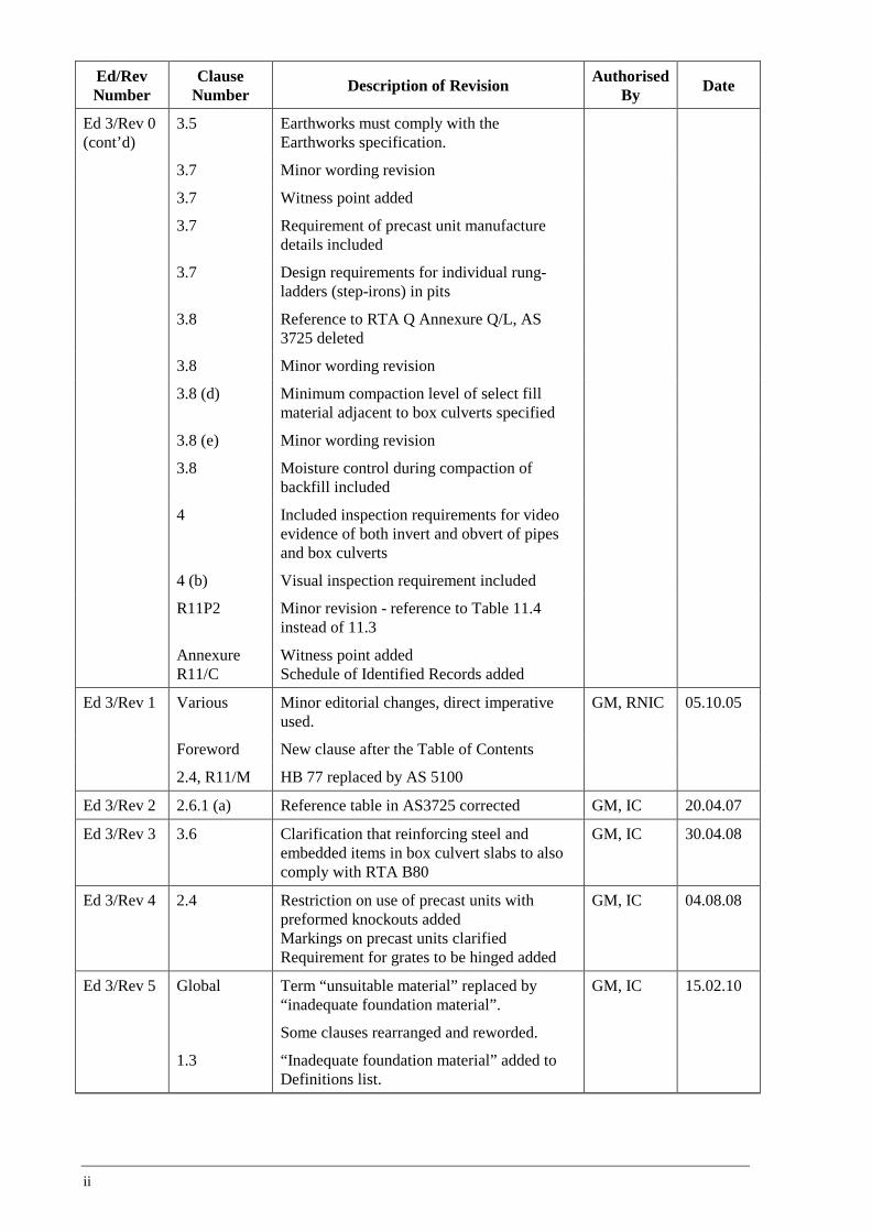
Ed 3/Rev 0 (cont’d)
3.5 Earthworks must comply with the Earthworks specification.
3.7 Minor wording revision
3.7 Witness point added
3.7 Requirement of precast unit manufacture details included
3.7 Design requirements for individual rung-ladders (step-irons) in pits
3.8 Reference to RTA Q Annexure Q/L, AS 3725 deleted
3.8 Minor wording revision
3.8 (d) Minimum compaction level of select fill material adjacent to box culverts specified
3.8 (e) Minor wording revision
3.8 Moisture control during compaction of backfill included
4 Included inspection requirements for video evidence of both invert and obvert of pipes and box culverts
4 (b) Visual inspection requirement included
R11P2 Minor revision - reference to Table 11.4 instead of 11.3
Annexure R11/C
Witness point added Schedule of Identified Records added
Ed 3/Rev 1 Various Minor editorial changes, direct imperative used.
GM, RNIC 05.10.05
Foreword New clause after the Table of Contents
2.4, R11/M HB 77 replaced by AS 5100
Ed 3/Rev 2 2.6.1 (a) Reference table in AS3725 corrected GM, IC 20.04.07
Ed 3/Rev 3 3.6 Clarification that reinforcing steel and embedded items in box culvert slabs to also comply with RTA B80
GM, IC 30.04.08
Ed 3/Rev 4 2.4 Restriction on use of precast units with preformed knockouts added Markings on precast units clarified Requirement for grates to be hinged added
GM, IC 04.08.08
Ed 3/Rev 5 Global Term “unsuitable material” replaced by “inadequate foundation material”.
Some clauses rearranged and reworded.
GM, IC 15.02.10
1.3 “Inadequate foundation material” added to Definitions list.
iii
Ed/Rev Number
Clause Number Description of Revision Authorised
By Date
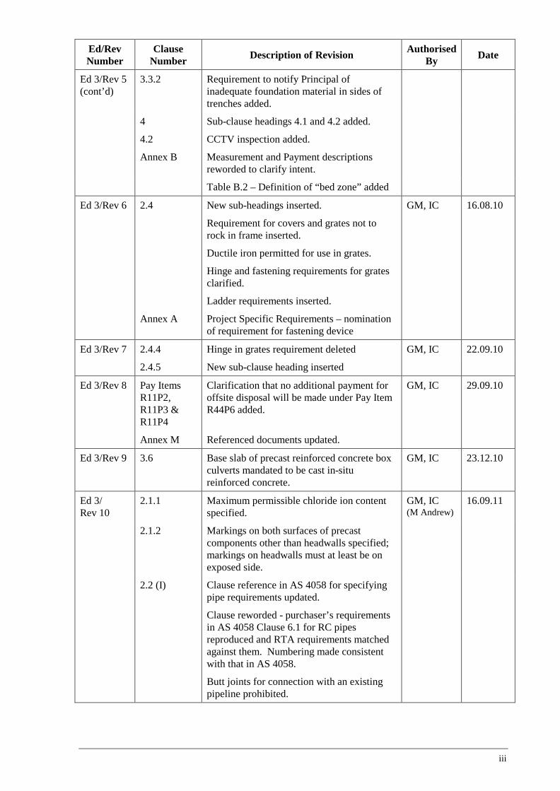
Ed 3/Rev 5 (cont’d)
3.3.2 Requirement to notify Principal of inadequate foundation material in sides of trenches added.
4 Sub-clause headings 4.1 and 4.2 added.
4.2 CCTV inspection added.
Annex B Measurement and Payment descriptions reworded to clarify intent.
Table B.2 – Definition of “bed zone” added
Ed 3/Rev 6 2.4 New sub-headings inserted.
Requirement for covers and grates not to rock in frame inserted.
Ductile iron permitted for use in grates.
Hinge and fastening requirements for grates clarified.
Ladder requirements inserted.
GM, IC 16.08.10
Annex A Project Specific Requirements – nomination of requirement for fastening device
Ed 3/Rev 7 2.4.4 Hinge in grates requirement deleted GM, IC 22.09.10
2.4.5 New sub-clause heading inserted
Ed 3/Rev 8 Pay Items R11P2, R11P3 & R11P4
Clarification that no additional payment for offsite disposal will be made under Pay Item R44P6 added.
GM, IC 29.09.10
Annex M Referenced documents updated.
Ed 3/Rev 9 3.6 Base slab of precast reinforced concrete box culverts mandated to be cast in-situ reinforced concrete.
GM, IC 23.12.10
Ed 3/ Rev 10
2.1.1 Maximum permissible chloride ion content specified.
GM, IC (M Andrew)
16.09.11
2.1.2 Markings on both surfaces of precast components other than headwalls specified; markings on headwalls must at least be on exposed side.
2.2 (I) Clause reference in AS 4058 for specifying pipe requirements updated.
Clause reworded - purchaser’s requirements in AS 4058 Clause 6.1 for RC pipes reproduced and RTA requirements matched against them. Numbering made consistent with that in AS 4058.
Butt joints for connection with an existing pipeline prohibited.
iv
Ed/Rev Number
Clause Number Description of Revision Authorised
By Date
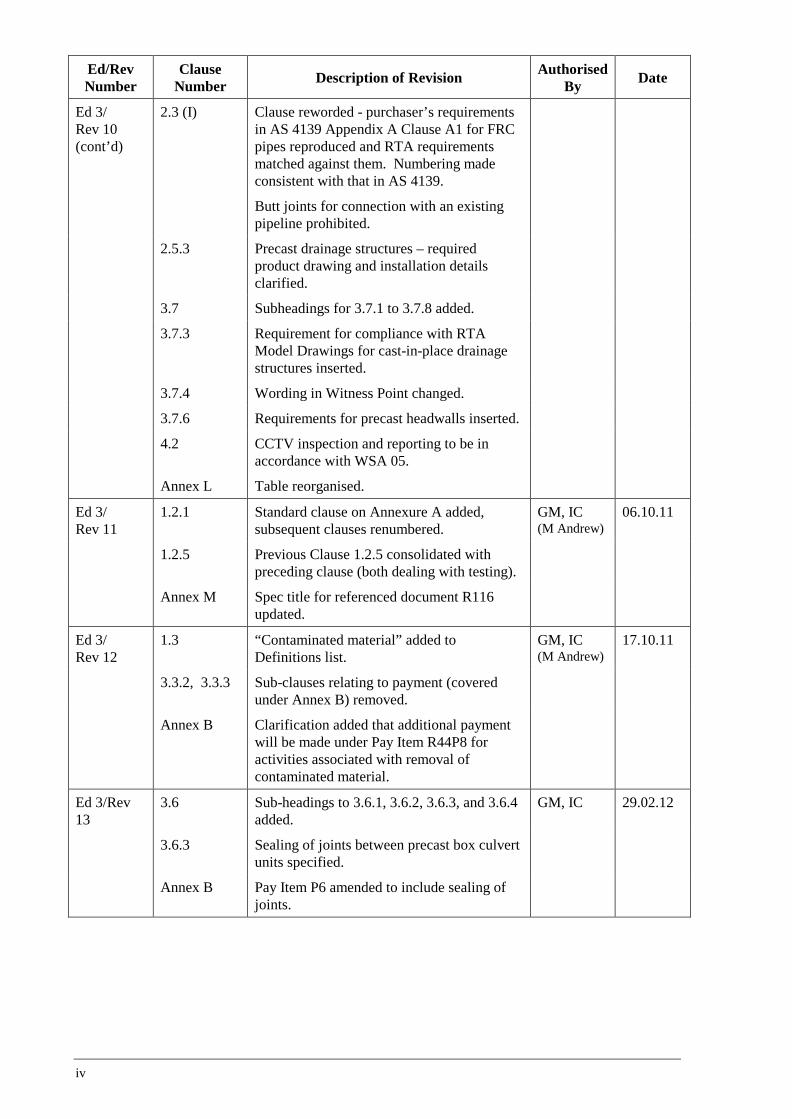
Ed 3/ Rev 10 (cont’d)
2.3 (I) Clause reworded - purchaser’s requirements in AS 4139 Appendix A Clause A1 for FRC pipes reproduced and RTA requirements matched against them. Numbering made consistent with that in AS 4139.
Butt joints for connection with an existing pipeline prohibited.
2.5.3 Precast drainage structures – required product drawing and installation details clarified.
3.7 Subheadings for 3.7.1 to 3.7.8 added.
3.7.3 Requirement for compliance with RTA Model Drawings for cast-in-place drainage structures inserted.
3.7.4 Wording in Witness Point changed.
3.7.6 Requirements for precast headwalls inserted.
4.2 CCTV inspection and reporting to be in accordance with WSA 05.
Annex L Table reorganised.
Ed 3/ Rev 11
1.2.1 Standard clause on Annexure A added, subsequent clauses renumbered.
GM, IC (M Andrew)
06.10.11
1.2.5 Previous Clause 1.2.5 consolidated with preceding clause (both dealing with testing).
Annex M Spec title for referenced document R116 updated.
Ed 3/ Rev 12
1.3 “Contaminated material” added to Definitions list.
GM, IC (M Andrew)
17.10.11
3.3.2, 3.3.3 Sub-clauses relating to payment (covered under Annex B) removed.
Annex B Clarification added that additional payment will be made under Pay Item R44P8 for activities associated with removal of contaminated material.
Ed 3/Rev 13
3.6 Sub-headings to 3.6.1, 3.6.2, 3.6.3, and 3.6.4 added.
GM, IC 29.02.12
3.6.3 Sealing of joints between precast box culvert units specified.
Annex B Pay Item P6 amended to include sealing of joints.
v
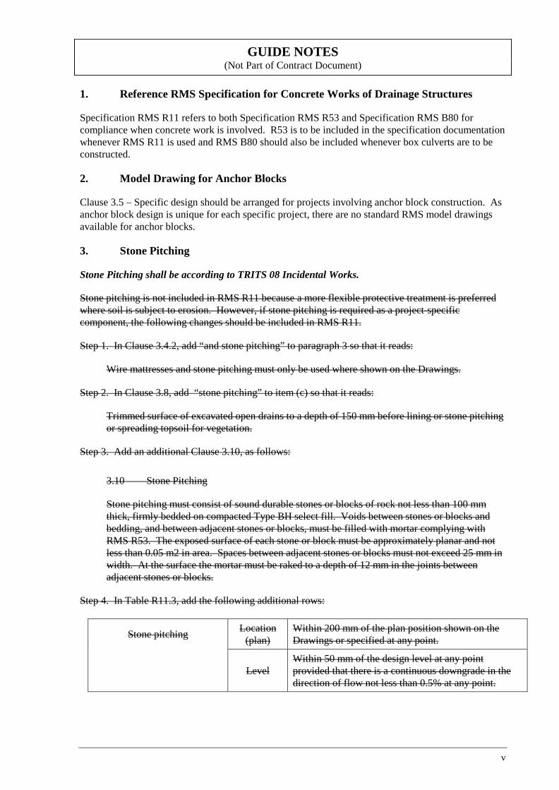
GUIDE NOTES (Not Part of Contract Document)
1. Reference RMS Specification for Concrete Works of Drainage Structures
Specification RMS R11 refers to both Specification RMS R53 and Specification RMS B80 for compliance when concrete work is involved. R53 is to be included in the specification documentation whenever RMS R11 is used and RMS B80 should also be included whenever box culverts are to be constructed.
2. Model Drawing for Anchor Blocks
Clause 3.5 – Specific design should be arranged for projects involving anchor block construction. As anchor block design is unique for each specific project, there are no standard RMS model drawings available for anchor blocks.
3. Stone Pitching
Stone Pitching shall be according to TRITS 08 Incidental Works.
Stone pitching is not included in RMS R11 because a more flexible protective treatment is preferred where soil is subject to erosion. However, if stone pitching is required as a project-specific component, the following changes should be included in RMS R11.
Step 1. In Clause 3.4.2, add “and stone pitching” to paragraph 3 so that it reads:
Wire mattresses and stone pitching must only be used where shown on the Drawings.
Step 2. In Clause 3.8, add “stone pitching” to item (c) so that it reads:
Trimmed surface of excavated open drains to a depth of 150 mm before lining or stone pitching or spreading topsoil for vegetation.
Step 3. Add an additional Clause 3.10, as follows:
3.10 Stone Pitching
Stone pitching must consist of sound durable stones or blocks of rock not less than 100 mm thick, firmly bedded on compacted Type BH select fill. Voids between stones or blocks and bedding, and between adjacent stones or blocks, must be filled with mortar complying with RMS R53. The exposed surface of each stone or block must be approximately planar and not less than 0.05 m2 in area. Spaces between adjacent stones or blocks must not exceed 25 mm in width. At the surface the mortar must be raked to a depth of 12 mm in the joints between adjacent stones or blocks.
Step 4. In Table R11.3, add the following additional rows:
Stone pitching Location (plan)
Within 200 mm of the plan position shown on the Drawings or specified at any point.
Level Within 50 mm of the design level at any point provided that there is a continuous downgrade in the direction of flow not less than 0.5% at any point.
vi
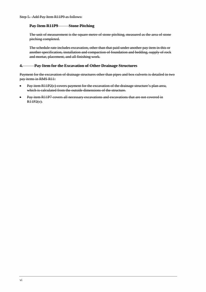
Step 5. Add Pay Item R11P9 as follows:
Pay Item R11P9 Stone Pitching
The unit of measurement is the square metre of stone pitching, measured as the area of stone pitching completed.
The schedule rate includes excavation, other than that paid under another pay item in this or another specification, installation and compaction of foundation and bedding, supply of rock and mortar, placement, and all finishing work.
4. Pay Item for the Excavation of Other Drainage Structures
Payment for the excavation of drainage structures other than pipes and box culverts is detailed in two pay items in RMS R11:
• Pay item R11P2(c) covers payment for the excavation of the drainage structure’s plan area, which is calculated from the outside dimensions of the structure.
• Pay item R11P7 covers all necessary excavations and excavations that are not covered in R11P2(c).
Edition 3 / Revision 13 ROADS AND MARITIME SERVICES February 2012
QA SPECIFICATION R11
STORMWATER DRAINAGE Copyright – Roads and Maritime Services
IC-QA-R11
VERSION FOR: DATE:

Stormwater Drainage R11
Ed 3 / Rev 13 i
CONTENTS
CLAUSE PAGE
FOREWORD .............................................................................................................................................. III RMS Copyright and Use of this Document ................................................................................. iii Revisions to Previous Version ..................................................................................................... iii Project Specific Changes ............................................................................................................. iii
1 GENERAL ........................................................................................................................................ 1 1.1 Scope .............................................................................................................................. 1 1.2 Structure of Specification ............................................................................................... 1 1.3 Definitions ...................................................................................................................... 2
2 MATERIALS .................................................................................................................................... 2 2.1 General ........................................................................................................................... 2 2.2 Precast Reinforced Concrete Pipes ................................................................................ 3 2.3 Fibre-reinforced Concrete Pipes ..................................................................................... 4 2.4 Precast Reinforced Concrete Box Culvert Units and Link Slabs ................................... 5 2.5 Other Drainage Structure Components .......................................................................... 5 2.6 Certificate of Conformity ............................................................................................... 7 2.7 Bedding, Support and Backfill Material ........................................................................ 7
3 CONSTRUCTION .............................................................................................................................. 8 3.1 General ........................................................................................................................... 8 3.2 Setting Out ...................................................................................................................... 8 3.3 Excavation for Drainage Structures ............................................................................... 9 3.4 Open Drains .................................................................................................................. 10 3.5 Precast Concrete and Fibre-reinforced Concrete Pipe Structures ................................ 12 3.6 Precast Reinforced Concrete Box Culvert Structures .................................................. 13 3.7 Drainage Structures Other Than Pipes and Box Culverts ............................................ 13 3.8 Compaction of Foundations, Bedding, Support And Backfill Material ....................... 15 3.9 Construction Traffic ..................................................................................................... 16
4 CONSTRUCTION TOLERANCES AND INSPECTION .......................................................................... 16 4.1 Construction Tolerances ............................................................................................... 16 4.2 Inspection ..................................................................................................................... 17 4.3 Rectification of Nonconformities ................................................................................. 18
ANNEXURE R11/A – PROJECT SPECIFIC REQUIREMENTS ...................................................................... 19 A.1 Fastening Device for Grates ......................................................................................... 19
ANNEXURE R11/B – MEASUREMENT AND PAYMENT ............................................................................ 20
ANNEXURE R11/C – SCHEDULES OF HOLD AND WITNESS POINTS AND IDENTIFIED RECORDS ............ 24 C1 Schedule of Hold and Witness Points .......................................................................... 24 C2 Schedule of Identified Records .................................................................................... 24
ANNEXURE R11/D – PLANNING DOCUMENTS ........................................................................................ 25
ANNEXURES R11/E TO R11/K – (NOT USED) ........................................................................................ 26
ANNEXURE R11/L – MINIMUM FREQUENCY OF TESTING ..................................................................... 26
R11 Stormwater Drainage
ii Ed 3 / Rev 13
ANNEXURE R11/M – REFERENCED DOCUMENTS................................................................................... 27
LAST PAGE OF THIS DOCUMENT IS .......................................................................................................... 28
Stormwater Drainage R11
Ed 3 / Rev 13 iii
FOREWORD
RMS COPYRIGHT AND USE OF THIS DOCUMENT
Copyright in this document belongs to the Roads and Maritime Services.
When this document forms part of a contract
This document should be read with all the documents forming the Contract.
When this document does not form part of a contract
This copy is not a controlled document. Observe the Notice that appears on the first page of the copy controlled by RMS. A full copy of the latest version of the document is available on the RMS Internet website: www.rta.nsw.gov.au/doingbusinesswithus/specifications
REVISIONS TO PREVIOUS VERSION
This document has been revised from RMS Specification R11 Edition 3 Revision 12.
All revisions to the previous version (other than minor editorial and project specific changes) are indicated by a vertical line in the margin as shown here, except when it is a new edition and the text has been extensively rewritten.
PROJECT SPECIFIC CHANGES
Any project specific changes have been indicated in the following manner:
(a) Text which is additional to the base document and which is included in the Specification is shown in bold italics e.g. Additional Text.
(b) Text which has been deleted from the base document and which is not included in the Specification is shown struck out e.g. Deleted Text.

(RMS COPYRIGHT AND USE OF THIS DOCUMENT - Refer to the Foreword after the Table of Contents)
Ed 3 / Rev 13 1
RMS QA SPECIFICATION R11
STORMWATER DRAINAGE
1 GENERAL
1.1 SCOPE
This Specification sets out the requirements for construction of stormwater drainage systems consisting of drainage structures and open drains.
1.2 STRUCTURE OF SPECIFICATION
This Specification includes a series of annexures that detail additional requirements.
1.2.1 Project Specific Requirements
Project specific details of work are shown in Annexure R11/A.
1.2.2 Measurement and Payment
The method of measurement and payment must comply with Annexure R11/B.
1.2.3 Schedules of HOLD POINTS, WITNESS POINTS and Identified Records
The schedules in Annexure R11/C list the HOLD POINTS and WITNESS POINTS that must be observed. Refer to RMS Q for definitions of HOLD POINTS and WITNESS POINTS.
The records listed in Annexure R11/C are Identified Records for the purposes of RMS Q Annexure Q/E.
1.2.4 Planning Documents
The PROJECT QUALITY PLAN must include each of the documents and requirements shown in Annexure R11/D and must be implemented.
If the Contract does not require you to implement a PROJECT QUALITY PLAN, the documents shown in Annexure R11/D must be submitted to the Principal for consideration at least 5 working days prior to work commencing and must be implemented.
1.2.5 Minimum Frequency of Testing
The Inspection and Test Plan must nominate the proposed testing frequency to verify conformity of the item, which must not be less than the frequency specified in Annexure R11/L.
Where a minimum frequency is not specified, nominate an appropriate frequency.
Sampling and testing of materials and components, including placed fill, must comply with RMS Q.
(RMS COPYRIGHT AND USE OF THIS DOCUMENT - Refer to the Foreword after the Table of Contents)
R11 Stormwater Drainage
2 Ed 3 / Rev 13
1.2.6 Referenced Documents
Unless otherwise specified the applicable issue of a reference document, other than an RMS Specification, is the issue current at the date one week before the closing date for tenders, or where no issue is current at that date, the most recent issue.
Standards, specifications and test methods are referred to in abbreviated form (e.g. AS 1234). For convenience, the full titles are given in Annexure R11/M.
1.3 DEFINITIONS
The terms “you” and “your” mean “the Contractor” and “the Contractor’s” respectively.
The following definitions are applicable to this Specification:
Contaminated material
Material classified as Restricted, Hazardous or Special Waste in accordance with EPA Waste Classification Guidelines.
Drainage structures
Devices to control stormwater flowing into and through a stormwater drainage system including culverts, inlet and outlet structures, junction boxes, gully pits, drop structures, headwalls, wingwalls, energy dissipators, and ancillary hardware such as grates, frames and step irons, as well as subsurface drainage pipes at pits, headwalls and wingwalls.
Geocomposite A permeable core enclosed in a geotextile.
Open drain An open channel constructed to intercept and redirect surface runoff water including catch drains, diversion drains, batter drains, inlet and outlet drains and diversion banks associated with stormwater drainage systems.
Inadequate Foundation Material
Material beneath or adjacent to the proposed drainage structure(s), which the Principal deems to be of insufficient strength to support the structure and loads on the structure, or material whose characteristics the Principal deems would adversely affect the performance or construction of the drainage structure.
Stormwater drainage system
One or more drainage structures and/or open drains arranged to collect and convey surface runoff water.
2 MATERIALS
2.1 GENERAL
2.1.1 Chloride Ion Content
The acid-soluble chloride ion content in concrete where steel reinforcement is present must not exceed 0.3 kg/m3 when tested in accordance with AS 1012.20.
2.1.2 Marking on Precast Components
For precast components with inner and outer surfaces, such as pipes or pits, markings must be made on both surfaces of the component.
(RMS COPYRIGHT AND USE OF THIS DOCUMENT - Refer to the Foreword after the Table of Contents)
Stormwater Drainage R11
Ed 3 / Rev 13 3
For precast headwalls, markings must be made, as a minimum, on the side of the component that will be exposed after installation.
2.2 PRECAST REINFORCED CONCRETE PIPES
The manufacturer must implement and maintain a Quality Management System in accordance with ISO 9001 as a means of ensuring that the pipe culvert components conform to the requirements of the Specification.
Precast reinforced concrete pipes must comply with AS 4058 and the following requirements:
(I) Referring to Clause 6.1 of AS 4058, the following apply:
(a) Intended service requirements:
(i) Application: drainage.
(ii) Installation environment: marine, unless specified or shown otherwise on the Drawings.
(b) Pipe size class or DN: as shown on the Drawings.
(c) Pipe load class: as shown on the Drawings.
(d) Pipe pressure or watertightness class:
(i) Non-pressure drainage pipes: (A) watertightness testing required. (B) New Zealand application: not applicable. (C) nominated field test pressure: 90 kPa.
acceptance criteria: no failure at either barrel or joint.
(ii) Pressure pipes: not applicable.
(e) Jacking loads: not applicable, unless pipe jacking is specified in the Drawings or approved or directed by the Principal.
(f) Pipe joint type: flexible, spigot and socket joint with rubber ring. Flush or butt joints must not be used.
(g) Confirm effective pipe length with supplier: not applicable.
(h) Elastomer type for elastomeric seal joints: must be natural rubber.
(i) Type tests and routine tests other than those “required” by Table 5.1 of AS 4058: routine tests as per item (d) above.
(j) Means of demonstrating finished product compliance: in accordance with AS 4058.
(k) Place and rate of delivery: advise purchaser of place and rate of delivery.
(l) Place of acceptance: advise purchaser if other than the place of manufacture.
(m) Specific requirements for cement: cement must comply with Clause 2.2.1 of AS 4058 and Clause 2.1.1 of this Specification.
(n) Type of admixtures: no variation from those permitted in Clause 2.2.5 of AS 4058.
(o) Other specific material requirements: other than the maximum chloride ion content specified in Clause 2.1.1 of this Specification, no variation from those permitted in Clauses 2.2 to 2.4 of AS 4058.
(RMS COPYRIGHT AND USE OF THIS DOCUMENT - Refer to the Foreword after the Table of Contents)
R11 Stormwater Drainage
4 Ed 3 / Rev 13
(p) Finishing and repair material specifications: no variation from those permitted by Clause 3.4.5 of AS 4058.
(q) Special pipe surface treatment or lining: not required, unless specified in the Drawings or directed by the Principal.
(r) Marking requirements, if other than on the outside of the pipe: must be duplicated on the inside of the pipe, in accordance with Clause 2.1.2 of this Specification.
(II) In addition:
(a) the design diameter as defined in AS 4058 must not be less than 95% of the nominal size shown on the Drawings for all classes of pipes up to and including Class 4.
(b) aggregates used in manufacture of reinforced concrete pipes must comply with Specification RMS R53.
2.3 FIBRE-REINFORCED CONCRETE PIPES
Fibre reinforced cement (FRC) pipes shall comply with the requirements of AS 4139. All FRC pipes shall be either single rubber or “supertite” double-vee rubber ring jointed. Rebated joints shall be mortared. Junctions in FRC pipe shall be installed in accordance with the appropriate manufacturer’s specification.
The manufacturer must implement and maintain a Quality Management System in accordance with ISO 9001 as a means of ensuring that the pipe culvert components conform to the requirements of the Specification.
Fibre-reinforced concrete pipes must comply with AS 4139 and the following requirements:
(I) Referring to Clause A1 in Appendix A of AS 4139, the following apply:
(a) Nominal pipe size: as shown on the Drawings.
(b) Intended application: drainage.
(c) Pipe load class and installation conditions: as shown on the Drawings.
(d) Type of joint: flexible, elastomeric, double V-ring joints, type (b)(i), as shown in Figure M1 in Appendix M of AS 4139. Elastomeric seals must comply with AS 1646. Butt joints must not be used.
(e) Tests other than those required by Clause 11.1 of AS 4139, “strength requirement”: not applicable.
(f) Any other special requirement: see (II) below.
(g) Specific requirements concerning repair of defects: not applicable. Pipes supplied with repaired defects must not be used in the Works.
(h) Statement of information supplied by manufacturer: provide to the Principal, before commencement of delivery to the site, all the information listed in Clause A2 of AS 4139 as well as the maximum recommended angular joint deflection.
(i) Place and rate of delivery: advise purchaser of place and rate of delivery.
(II) In addition:
(a) the internal diameter must not be less than 95% of the nominal size shown on the Drawings for all classes of pipes.
(RMS COPYRIGHT AND USE OF THIS DOCUMENT - Refer to the Foreword after the Table of Contents)
Stormwater Drainage R11
Ed 3 / Rev 13 5
2.4 PRECAST REINFORCED CONCRETE BOX CULVERT UNITS AND LINK SLABS
Design, test, manufacture, and deliver to site precast concrete box culvert units in accordance with Specification RMS R16.
2.5 OTHER DRAINAGE STRUCTURE COMPONENTS
2.5.1 General
Drainage structure components, other than those described in Clauses 2.2 to 2.4 inclusive, may be:
(a) cast-in-place; or
(b) standard precast items; or
(c) specially designed and manufactured for the function intended;
in accordance with the Drawings and/or other Contract Documents.
Cast-in-place concrete, other than for precast concrete box culvert invert slabs (refer to Clause 3.6) must comply with RMS R53.
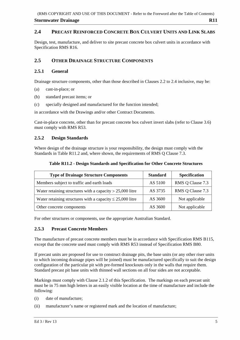
2.5.2 Design Standards
Where design of the drainage structure is your responsibility, the design must comply with the Standards in Table R11.2 and, where shown, the requirements of RMS Q Clause 7.3.
Table R11.2 - Design Standards and Specification for Other Concrete Structures
Type of Drainage Structure Components Standard Specification
Members subject to traffic and earth loads AS 5100 RMS Q Clause 7.3
Water retaining structures with a capacity > 25,000 litre AS 3735 RMS Q Clause 7.3
Water retaining structures with a capacity ≤ 25,000 litre AS 3600 Not applicable
Other concrete components AS 3600 Not applicable
For other structures or components, use the appropriate Australian Standard.
2.5.3 Precast Concrete Members
The manufacture of precast concrete members must be in accordance with Specification RMS B115, except that the concrete used must comply with RMS R53 instead of Specification RMS B80.
If precast units are proposed for use to construct drainage pits, the base units (or any other riser units to which incoming drainage pipes will be joined) must be manufactured specifically to suit the design configuration of the particular pit with pre-formed knockouts only in the walls that require them. Standard precast pit base units with thinned wall sections on all four sides are not acceptable.
Markings must comply with Clause 2.1.2 of this Specification. The markings on each precast unit must be in 75 mm high letters in an easily visible location at the time of manufacture and include the following:
(i) date of manufacture;
(ii) manufacturer’s name or registered mark and the location of manufacture;
(RMS COPYRIGHT AND USE OF THIS DOCUMENT - Refer to the Foreword after the Table of Contents)
R11 Stormwater Drainage
6 Ed 3 / Rev 13
(iii) maximum mass of unit in kilograms;
(iv) any other identification necessary to directly relate the unit to tested samples, e.g. batch number; and
(v) inspection status.
Where precast drainage structures are shown on the Drawings or are proposed by you, include in the Quality Records:
(a) design documentation, signed by a structural engineer eligible for Corporate Membership of the Institution of Engineers, Australia and experienced in the design of structures, certifying their suitability for each particular application;
(b) product drawings including the full dimensions of the concrete product, all reinforcement details, cover, recommended attachment to adjoining structures and design lifting points;
(c) methods for manufacture, testing and installation including, where applicable, clearance to pit shaft ends, pipe to pit jointing, headwall to cast-in-situ curtain wall structure attachment and step iron positioning.
HOLD POINT
Process Held: Supply of precast concrete structures subject to traffic loads and/or earth pressure and water retaining structures with a capacity in excess of 25,000 litres.
Submission Details: The documents specified above, as applicable, at least 7 days prior to the date supplying the precast structures.
Release of Hold Point: The Principal will consider the documents and may audit the quality records prior to authorising the release of the Hold Point.
Where any of the above documents have been submitted previously to the Principal, not more than 36 months prior to their intended use, you may submit, in lieu of submission of the documents, the identity of these records and certify their applicability to this Contract.
Where you propose to install precast drainage structures which are not detailed on the Drawings, submit the proposal for approval for consideration by the Principal in accordance with the General Conditions of Contract.
The construction of the precast manhole and the in-situ base shall be in accordance with ACT Water Supply and Sewerage Standards, Drawing WSS057 except that the precast cover and ring shall be in accordance with Standard Drawing ST-0017.
2.5.4 Access Covers, Grates and Frames
Metal access covers, road grates and frames must comply with AS 3996. Covers and grates must not rock in their frame.
Access covers must be Class D, unsealed, solid-top or recessed with concrete infill, and manufactured from cast iron and must be marked with the letters "SW".
Grates and frames must be Class D, bicycle safe and manufactured from galvanised steel or ductile iron unless otherwise specified or shown on the Drawings. Where specified in Annexure R11/A, grates must include a fastening device which prevents their opening without the use of a tool.
(RMS COPYRIGHT AND USE OF THIS DOCUMENT - Refer to the Foreword after the Table of Contents)
Stormwater Drainage R11
Ed 3 / Rev 13 7
Surface openings for grates in footpaths must comply with the requirements of AS 3996 for pedestrian areas. Access covers must be heavy duty covers and frames at least equivalent to Gatic heavy circular covers with minimum 600mm clear opening installed.
Finish access covers flush with pavement in paved areas, 25mm above finished surface in landscaped areas and 75mm above natural surface elsewhere.
2.5.5 Ladders and Step Irons
Ladders, including individual-rung ladders (step irons), must comply with AS 1657. Vertical ladders are permitted and the minimum side clearance of 450 mm (measured from the centre-line) may be reduced to 300 mm when the pit wall is less than 900 mm long (refer Clause 5.1 of AS 1657). Ladders must be fabricated from steel and hot-dip galvanised in accordance with AS/NZS 4680 after fabrication.
2.6 CERTIFICATE OF CONFORMITY
Prior to incorporating into the Works any pipes, culverts, precast concrete units, access covers, road grates or frames, provide the Principal with a signed Certificate verifying that the materials and components conform with the requirements of this Specification.
The Certificate described above must identify the item and record the inspection and test records that verify conformity and must be available for inspection as part of the Quality Records.
HOLD POINT
Process Held: Incorporation into the Works of pipes, culverts, precast concrete units, access covers, road grates or frames.
Submission Details: Certificates of Conformity, at least 7 days prior to incorporation in the Works.
Release of Hold Point: The Principal may audit the quality records prior to authorising the release of the Hold Point.
2.7 BEDDING, SUPPORT AND BACKFILL MATERIAL
Crushed recycled building materials may be used as a bedding material and side support material, provided it meets the requirements as set for use. You shall obtain sample coarse particle size distributions from the supplier which is representative of the material to be used on site and submit them to the Principal for approval prior to use.
2.7.1 Bed and Haunch Zones
Material for Bed and Haunch zones must consist of Type BH select fill. Type BH select fill must have:
(a) a particle size distribution, determined by Test Method RMS T201, within the limits set out in Table 6 in AS 3725; and
(b) a Plasticity Index, determined by Test Method RMS T109, of not more than 6.
(RMS COPYRIGHT AND USE OF THIS DOCUMENT - Refer to the Foreword after the Table of Contents)
R11 Stormwater Drainage
8 Ed 3 / Rev 13
2.7.2 Side and Overlay Zones
Material for Side and Overlay zones of pipes and box culverts and adjacent to other drainage structures must consist of Type SO select fill. The dimensions of Type SO select fill must not exceed 50 mm, and the Plasticity Index, as determined by Test Method RMS T109, must be between 2 and 12.
2.7.3 Material Adjacent to Weepholes
Material adjacent to weepholes must consist of clean, graded, hard and durable broken stone or river gravel with nominal particle sizes between 50 mm and 10 mm such that:
(a) the maximum particle dimension does not exceed 50 mm; and
(b) no more than 5% by mass passes the 9.5 mm AS sieve.
3 CONSTRUCTION
3.1 GENERAL
Construction of stormwater drainage includes:
(a) excavation, including preparation of foundations for box culverts, supply, bedding, laying, installation and jointing drainage structures;
(b) provision of anchoring systems including anchor blocks;
(c) supply, placing and compacting select fill;
(d) supply, placing and compacting granular and geocomposite material at weepholes; and
(e) supply and placing subsurface pipes and filter fabric at pits, headwalls and wingwalls.
Where subsoil drains discharge into drainage structures the penetration through the wall shall be sleeved with 100mm diameter uPVC pipes.
Where detailed connect drains to existing manholes, sumps or pipes. Break out existing structures to the minimum extent necessary and reinstate on completion of the connection.
3.2 SETTING OUT
Set out the stormwater drainage systems as shown on the Drawings in sufficient detail to identify:
(a) the location, lengths and levels at outlets and inlets of pipes and box culvert structures;
(b) the locations and levels of gully pits, junction boxes, energy dissipators, and inlet and outlet structures;
(c) the locations and levels of the ends of wingwalls and headwalls; and
(d) the locations and levels of open drains.
(RMS COPYRIGHT AND USE OF THIS DOCUMENT - Refer to the Foreword after the Table of Contents)
Stormwater Drainage R11
Ed 3 / Rev 13 9
HOLD POINT
Process Held: Construction of each drainage system.
Submission Details: Notify the Principal: - that the drainage system has been set out; and - of any changes to the design proposed by you.
Release of Hold Point: The Principal will inspect the set out, including any changes proposed and, if necessary, amend the design to suit actual site conditions prior to authorising the release of the Hold Point.
Unless otherwise shown on the Drawings, locate catch drains at least 2.5 m from the tops of cuttings or the toes of embankments and not more than is necessary to maintain the specified grades.
Extend open drains as necessary to natural drainage depressions or to a drainage system.
The inlet or outlet locations or design levels or the drainage structure length may be amended by the Principal to suit actual site conditions. Payment for any amendments directed by the Principal will be at scheduled rates or as determined by the Principal. Payment will not be made for any amendment that is made to suit your construction procedures.
3.3 EXCAVATION FOR DRAINAGE STRUCTURES
3.3.1 General
For each part of a drainage system, complete the required erosion and sedimentation control measures before the commencement of drainage works (except those parts of the drainage system forming part of the control measures).
Unless otherwise shown on the Contract drawings, the pipes shall be laid in trench conditions.
The width of trench excavations for pipelines must be in accordance with AS 3725.
Extend excavation for drainage structures other than pipes so that, at all points on the walls of the structure, the clear width between the structure wall and the face of the excavation is at least 300 mm or one third of the height of the face of the excavation, whichever is the greater.
The side zones of pipe trenches must comply with the density and stiffness requirements of AS 3725 Clause 9.2.3.1 for Type HS3 support.
WITNESS POINT
Process: Excavation for pipes
Submission Details: Notify the Principal not less than 24 hours and not more than 5 clear working days prior to the intended time of completing the excavation, that the excavation, including preparation of foundations and sides of trenches, will be completed.
(RMS COPYRIGHT AND USE OF THIS DOCUMENT - Refer to the Foreword after the Table of Contents)
R11 Stormwater Drainage
10 Ed 3 / Rev 13
3.3.2 Inadequate Foundation Material
Notify the Principal of any area of the foundation which may contain material that is inadequate to support the proposed drainage structure. If the Principal agrees that the material is inadequate foundation material, or any areas of the foundations are so deemed by the Principal, the Principal may direct the removal and replacement of this material. Dispose of such material in accordance with Specification RMS R44.
Where the sides of trenches for drainage structures are composed of material which may require removal and replacement, notify the Principal of such material. The Principal may direct removal, disposal and replacement of that material.
HOLD POINT
Process Held: Replacement of inadequate foundation material.
Submission Details: Notification that inadequate foundation material has been excavated to the extent directed.
Release of Hold Point: The Principal will inspect the excavation and may direct further excavation prior to authorising the release of the Hold Point.
Replace inadequate foundation material with materials from cuttings, or with other material acceptable to the Principal, and compact to the requirements of Clause 3.8 of this Specification.
3.3.3 Backfill of Trenches and Disposal of Surplus Excavated Material
Backfill the drainage trench with material excavated from the trench where it is deemed to be suitable for backfill by the Principal or otherwise use materials from cuttings or other material acceptable to the Principal, and compact to the requirements of Clause 3.8 of this Specification.
Dispose of any surplus excavated material off site in accordance with Specification RMS R44 unless the Principal directs or approves its use in the construction of embankments, or at other locations within the Site.
3.4 OPEN DRAINS
3.4.1 General
Excavate open drains (including topsoil) to the dimensions shown on the Drawings. Where dimensions are not shown, the minimum depth is 300 mm, the minimum waterway area is 0.2 m2 and the batter slope must not be steeper than 2:1 (horizontal : vertical).
Where construction of an earth structure is required to form an open drain, clear, grub, strip of topsoil, and deal with inadequate foundation material for open drains in accordance with the requirements of Clause 3.3.2.
Remove any inadequate foundation material from the foundation area before commencing to place material for the earth structure. Construct the earth structure in layers not exceeding 200 mm in depth, and compact to the requirements of Clause 3.8. On completion of its construction, vegetate in accordance with Specification RMS R178.
(RMS COPYRIGHT AND USE OF THIS DOCUMENT - Refer to the Foreword after the Table of Contents)
Stormwater Drainage R11
Ed 3 / Rev 13 11
Deal with surplus materials from the construction of open drains in accordance with the requirements of Clause 3.3.3.
Trim open drains to a uniform surface free of irregularities. Compact the surfaces of drains to be lined to the requirements of Clause 3.8.
Open drains must be graded to ensure free flow of water and must have a grade of not less than 0.5%.
HOLD POINT
Process Held: Construction of open drains with grade less than 0.5%.
Submission Details: Notification that 0.5% minimum grade cannot be achieved.
Release of Hold Point: The Principal will give directions and authorise the release of the Hold Point.
3.4.2 Lining
Unless otherwise shown on the Drawings or directed by the Principal, line open drains with:
(a) organic fibre mat and vegetation where the longitudinal grade of the completed drain lies between 1% and 5% inclusive; or
(b) concrete where the longitudinal grade of the completed drain is less than 1% or greater than 5%;
Concrete lining must have a minimum compacted thickness of 100 mm measured at right angles to the surface of the lining, and must be coloured to match that of the surrounding materials, or as directed by the Principal.
Only use wire mattresses where shown on the Drawings.
Install linings in accordance with the following Specifications:
Lining Specification
Cast-in-place concrete and sprayed concrete RMS R53
Wire mattresses RMS R55
Organic fibre mat RMS R178
3.4.3 Movement Joints
Control cracking in concrete lining by providing movement joints. Movement joints must be:
(a) straight narrow grooves, at 90° (± 5°) to the line of the drain, 20 (± 5) mm deep, and spaced at intervals of not more than 3.0 m along the open drain; and with
(b) expansion joint material installed at 15 m intervals, for the full depth of the lining and complying with RMS 3204.
3.4.4 Diversion Banks
Material forming a diversion bank must have:
(RMS COPYRIGHT AND USE OF THIS DOCUMENT - Refer to the Foreword after the Table of Contents)
R11 Stormwater Drainage
12 Ed 3 / Rev 13
(a) a Plasticity Index, determined by RMS T109, of between 15 and 30 inclusive; and
(b) a particle size distribution, determined by RMS T107, such that between 20% and 60% inclusive by mass of material passes the 425 micron sieve.
3.5 PRECAST CONCRETE AND FIBRE-REINFORCED CONCRETE PIPE STRUCTURES
Unless otherwise specified, commence laying pipes at the outlet end and proceed upstream.
Remove all foreign matter from inside and outside of pipes before laying.
Installation must be in accordance with AS 3725 with Type HS3 support.
Where “Embankment Installation” condition is specified, prior to commencement of placing bedding and laying pipes, place and compact embankment fill to a height above the top of the bed zone of at least 0.7 times the external diameter of the pipe and for a minimum lateral distance outside each trench wall of 2.5 times the external diameter of the pipe. Comply with Specification RMS R44 when placing earth fill.
Provide an alternative waterway area unless otherwise approved by the Principal.
Where “Trench Installation” condition is specified for pipes in an embankment, complete the embankment to the underside of the Selected Material Zone prior to the commencement of the excavation.
Lay pipes with the socket end placed upstream.
Provide anchor blocks at a maximum spacing of 3 m and at bends or junctions for all stormwater pipes laid on a grade exceeding 20% and where shown on the Drawings. Construct anchor blocks as shown on the Drawings. Place in-situ concrete directly against all faces of the keys in the sides and base of the trench.
Where pipes are to be laid to a curved alignment it must be concentric with the curved line. Curved pipelines shall be made by either deflections at each joint or by the use of splayed pipes as specified on the Contract drawings.
For curved pipelines, the minimum radius for standard pipes shall be according to the manufacturer’s recommendation. When splayed pipes are used the splays shall be either factory formed or splays formed in the field by the cutting of standard pipes. The length of field splayed pipes at the outside spring line shall be 1200mm maximum and 900mm minimum.
Curved lines in FRC pipes can be achieved by the use of either standard 11.25 degree bends or by deflecting the pipes at the joints. The maximum deflection shall be in accordance with the manufacturer’s recommendations.
When using a rubber ring jointing system, form joints by placing ring evenly over the pipe spigot without twist and rolling it into the socket. Spigots shall always be inserted squarely into sockets. If line is to be curved, deflect pipe after making joint.
Install subsurface drainage pipe, complying with Specification RMS 3552, at the discharge end of pipes at gully pits, junction boxes and at headwalls unless the Drawings specifically direct the subsurface drainage be omitted.
(RMS COPYRIGHT AND USE OF THIS DOCUMENT - Refer to the Foreword after the Table of Contents)
Stormwater Drainage R11
Ed 3 / Rev 13 13
Unless otherwise shown on the Drawings, the subsurface drainage pipe must be a 3 m length of 100 mm diameter subsoil pipe laid beside and 100 mm above the invert level of the drainage pipe discharging through the wall of the pit or headwall. The subsoil pipe must be straight and discharge through the same wall as the drainage pipe. Seal the subsoil pipe at the upstream end and enclose it in a seamless tubular filter fabric complying with RMS 3553.
Seal lifting holes in all pipes and flush or butt joints used to extend existing pipes, to prevent the ingress of materials.
3.6 PRECAST REINFORCED CONCRETE BOX CULVERT STRUCTURES
3.6.1 Foundation
Where rock is encountered over part of the foundation, excavate the whole of the foundation to a depth of 300 mm below the level of the bottom of the plain concrete and replace it with material complying with AS 1597.2 Clause 6.3.
3.6.2 Base Slab and Link Slab
Base slabs of precast reinforced concrete box culverts must be cast in-situ reinforced concrete, cast on a blinding layer of 50 mm thick plain concrete.
Concrete work, including reinforcing steel and other embedded items, for cast in-situ invert slabs and link slabs must comply with RMS B80.
Plain concrete must comply with RMS R53.
When two or more rows of parallel box sections are to be constructed together, they shall be laid on a single cast insitu slab. Provide clearance as detailed between lines and fill space with mortar or grout.
3.6.3 Installation
After installation of the precast crown units, seal the transverse joint between adjacent units all round with a 250 mm wide, self-adhering membrane of rubberised asphalt integrally bonded to polypropylene mesh (e.g. Bituthene or approved equivalent), of minimum 1.6 mm thickness, unless shown otherwise in the Drawings.
Seal lifting holes to prevent the ingress of materials. Cut lifting hooks and coat the exposed steel to prevent corrosion.
3.6.4 Backfilling
During backfilling, prevent wedge action between the excavation and the walls of the structure by compacting adjacent to the structure first and moving outwards to the face of the excavation.
3.7 DRAINAGE STRUCTURES OTHER THAN PIPES AND BOX CULVERTS
3.7.1 General
Drainage structures other than pipes and box culverts include inlet and outlet structures, junction boxes, gully pits, drop structures, headwalls, wingwalls and energy dissipators.
(RMS COPYRIGHT AND USE OF THIS DOCUMENT - Refer to the Foreword after the Table of Contents)
R11 Stormwater Drainage
14 Ed 3 / Rev 13
Install drainage structures other than pipes and box culverts as soon as possible and not later than 14 days after the installation of associated pipes, box culverts or open drains.
Where existing structures are to be raised or lowered, break out sufficient of the walls to expose reinforcement and to allow at least 150mm of new concrete below the new cover or frame. Splice new reinforcement to old as necessary, form and place concrete as specified for new structures.
3.7.2 Isolation Joint
Install an isolation joint where a drainage structure will abut a structure or concrete pavement. The isolation joint must be 10 mm wide using preformed jointing filler complying with RMS 3204.
3.7.3 Cast-in-Place Concrete Drainage Structures
Cast-in-place concrete drainage structures must comply with Specification RMS R53 and RMS Model Drawings where applicable.
Do not backfill against cast-in-place concrete drainage structures within 14 days of placing the concrete in these structures, unless authorised by the Principal.
Formwork shall comply with the requirements of TRITS 10 – Major Concrete Work. Both internal and external surfaces of walls shall be formed, however where the depth of the structure and nature of the ground permit, walls may be cast without external forms provided the ground is undisturbed, that it is trimmed to an even vertical surface and that wall thickness is increased by at least 50mm over that detailed. No additional payment will be allowed for this alternative procedure. External formwork shall be used for the top 300mm of manholes and sumps in all cases. Formwork shall be used for both faces of endwalls.
Construct manholes and sumps with blockouts for connection of future pipelines as detailed.
HOLD POINT
Process Held: Placement of Concrete in Cast-in-Place reinforced concrete structures
Submission Details: A Certificate of compliance signed by you covering the installation of reinforcement (ie cover, spacing, splicing, etc) and compliance of formwork in accordance with the Contract requirements.
Release of Hold Point: The Principal will consider the submitted documents and may inspect the works prior to authorising the release of the Hold Point.
3.7.4 Installation
WITNESS POINT
Process witnessed: Installation of drainage structures other than pipes and box culverts.
Submission Details: Notify the Principal at least 7 days prior to the date of commencement of the work.
(RMS COPYRIGHT AND USE OF THIS DOCUMENT - Refer to the Foreword after the Table of Contents)
Stormwater Drainage R11
Ed 3 / Rev 13 15
3.7.5 Foundation
Drainage structures, other than pipes or box culverts, must be uniformly supported by providing an unreinforced concrete foundation not less than 50 mm thick, complying with RMS R53.
3.7.6 Precast Units
Where precast units are used for drainage structures, install the units in accordance with this Specification and the manufacturer’s recommendations.
Precast headwalls for pipes of 300 mm to 1200 mm diameter must comply with RMS Model Drawings to ensure that a curtain wall is provided at the outer edge of the apron. Precast headwalls for pipes greater than 1200 mm diameter must not be used unless approved otherwise by the Principal.
Multi-piece modular precast headwalls are not acceptable unless approved otherwise by the Principal.
3.7.7 Ladder
In each junction box, gully pit, drop structure, etc deeper than 600 mm, install an individual-rung ladder (step irons) in accordance with AS 1657 on one internal wall for the full depth of the structure. The top of the uppermost rung must not be more than 600 mm below the top of the pit. The top of the bottom rung must not be more than 500 mm or less than 300 mm above the invert of the pit. Rung spacings must be 300 mm ± 50 mm.
3.7.8 Weepholes
Where weepholes are provided in headwalls, endwalls and wingwalls, place broken stone or river gravel as specified in Clause 2.6, to a height of not less than 450 mm above the bottom of the weephole over a plan area of not less than 600 mm along the wall by 300 mm out from the wall located centrally about the weephole.
Enclose the broken stone or river gravel with geotextile filter fabric complying with Specification RMS R63. Alternatively, at weepholes, cover the facial area of the structure with an equivalent area of geocomposite.
3.8 COMPACTION OF FOUNDATIONS, BEDDING, SUPPORT AND BACKFILL MATERIAL
Except where specified otherwise or unless directed otherwise by the Principal, compact all foundations, bedding, support and backfill material in layers not exceeding 150 mm compacted thickness.
Compact foundations and backfill material so that the minimum characteristic value of relative compaction when tested in accordance with RMS Q Annexure Q/L is as follows: (a) Backfill material within the Selected Material Zone 100%
(b) Foundations and trench bases to a depth of 150 mm below the bottom of the plain concrete or of the bed zone
95%
(c) Trimmed surface of excavated open drains to a depth of 150 mm, before lining or spreading topsoil for vegetation
90%
(d) Select fill adjacent to box culverts 98%
(RMS COPYRIGHT AND USE OF THIS DOCUMENT - Refer to the Foreword after the Table of Contents)
R11 Stormwater Drainage
16 Ed 3 / Rev 13
(e) All other fill material for drainage structures including select fill in the bed, haunch, side and overlay zones, material replacing inadequate foundation material, backfill material and earth material in diversion banks
95%
RMS Test Method T173 may be used to determine the field (in situ) density provided the testing is carried out in accordance with the Sampling and Testing Clause of the RMS Specification for EARTHWORKS and you demonstrate that such testing produces equivalent results for each trench to those obtained using Test Method RMS T119.
Control the moisture content of the foundations, bedding, support, and backfill material to prevent loss of density and strength in nearby earthworks through over wetting.
3.9 CONSTRUCTION TRAFFIC
Where you propose to move heavy construction plant and vehicles over pipe or box culvert structures, design and provide protective measures for each crossing in accordance with Specification RMS G2.
HOLD POINT
Process Held: Moving heavy construction plant or vehicles over pipe or box culvert structures.
Submission Details: Certificate and verification of protective measures.
Release of Hold Point: The Principal may examine the submitted documents, prior to authorising the release of the Hold Point.
4 CONSTRUCTION TOLERANCES AND INSPECTION
4.1 CONSTRUCTION TOLERANCES
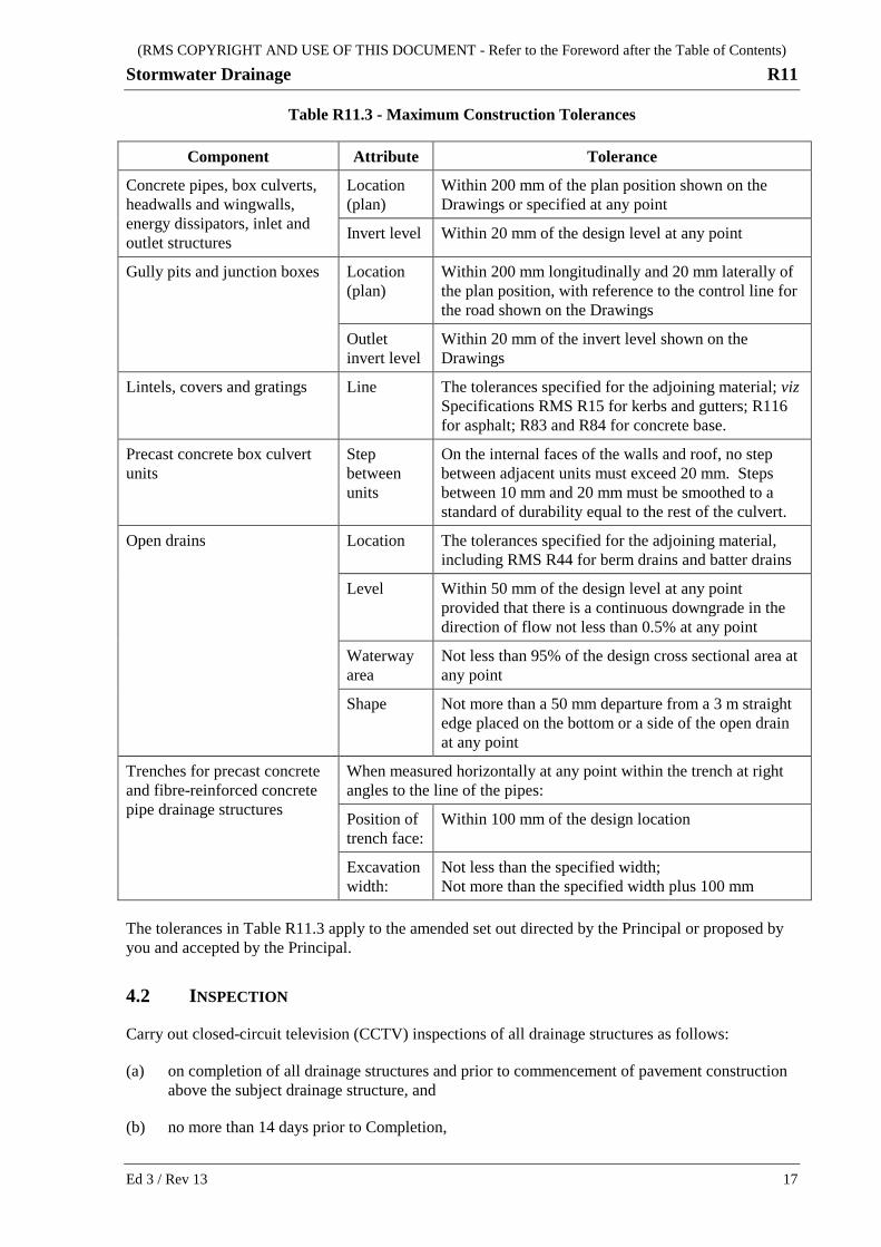
Construct the stormwater drainage system so that water flows through the system without unintended ponding, and within the construction tolerances in Table R11.3:
(RMS COPYRIGHT AND USE OF THIS DOCUMENT - Refer to the Foreword after the Table of Contents)
Stormwater Drainage R11
Ed 3 / Rev 13 17
Table R11.3 - Maximum Construction Tolerances
Component Attribute Tolerance
Concrete pipes, box culverts, headwalls and wingwalls, energy dissipators, inlet and outlet structures
Location (plan)
Within 200 mm of the plan position shown on the Drawings or specified at any point
Invert level Within 20 mm of the design level at any point
Gully pits and junction boxes Location (plan)
Within 200 mm longitudinally and 20 mm laterally of the plan position, with reference to the control line for the road shown on the Drawings
Outlet invert level
Within 20 mm of the invert level shown on the Drawings
Lintels, covers and gratings Line The tolerances specified for the adjoining material; viz Specifications RMS R15 for kerbs and gutters; R116 for asphalt; R83 and R84 for concrete base.
Precast concrete box culvert units
Step between units
On the internal faces of the walls and roof, no step between adjacent units must exceed 20 mm. Steps between 10 mm and 20 mm must be smoothed to a standard of durability equal to the rest of the culvert.
Open drains Location The tolerances specified for the adjoining material, including RMS R44 for berm drains and batter drains
Level Within 50 mm of the design level at any point provided that there is a continuous downgrade in the direction of flow not less than 0.5% at any point
Waterway area
Not less than 95% of the design cross sectional area at any point
Shape Not more than a 50 mm departure from a 3 m straight edge placed on the bottom or a side of the open drain at any point
Trenches for precast concrete and fibre-reinforced concrete pipe drainage structures
When measured horizontally at any point within the trench at right angles to the line of the pipes:
Position of trench face:
Within 100 mm of the design location
Excavation width:
Not less than the specified width; Not more than the specified width plus 100 mm
The tolerances in Table R11.3 apply to the amended set out directed by the Principal or proposed by you and accepted by the Principal.
4.2 INSPECTION
Carry out closed-circuit television (CCTV) inspections of all drainage structures as follows:
(a) on completion of all drainage structures and prior to commencement of pavement construction above the subject drainage structure, and
(b) no more than 14 days prior to Completion,
(RMS COPYRIGHT AND USE OF THIS DOCUMENT - Refer to the Foreword after the Table of Contents)
R11 Stormwater Drainage
18 Ed 3 / Rev 13
to verify that the works are within the specified tolerances, the flow of water is not obstructed by surplus construction material and to check for visible signs of defects.
On completion of the inspections, submit to the Principal a report of these inspections and any nonconformity detected, including video evidence of both the invert and obvert of pipes and box culverts with small openings.
The inspection and reporting must be accordance with WSA 05 – 2008.
4.3 RECTIFICATION OF NONCONFORMITIES
Nonconformities must be dealt with in accordance with Specification RMS Q.
(RMS COPYRIGHT AND USE OF THIS DOCUMENT - Refer to the Foreword after the Table of Contents)
Stormwater Drainage R11
Ed 3 / Rev 13 19
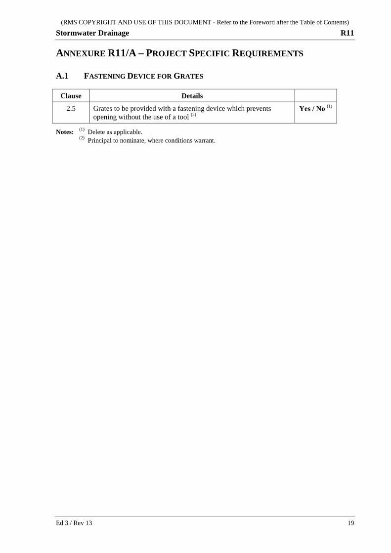
ANNEXURE R11/A – PROJECT SPECIFIC REQUIREMENTS
A.1 FASTENING DEVICE FOR GRATES
Clause Details
2.5 Grates to be provided with a fastening device which prevents opening without the use of a tool (2)
Yes / No (1)
Notes: (1) Delete as applicable. (2) Principal to nominate, where conditions warrant.
(RMS COPYRIGHT AND USE OF THIS DOCUMENT - Refer to the Foreword after the Table of Contents)
R11 Stormwater Drainage
20 Ed 3 / Rev 13
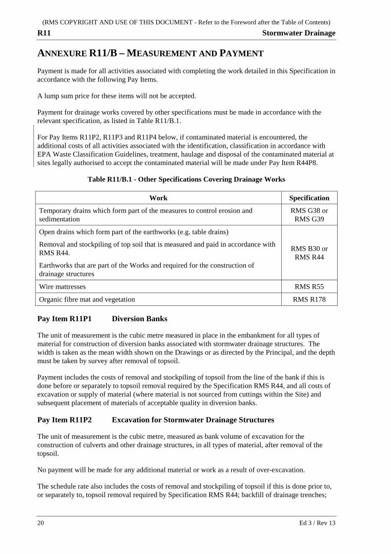
ANNEXURE R11/B – MEASUREMENT AND PAYMENT Payment is made for all activities associated with completing the work detailed in this Specification in accordance with the following Pay Items.
A lump sum price for these items will not be accepted.
Payment for drainage works covered by other specifications must be made in accordance with the relevant specification, as listed in Table R11/B.1.
For Pay Items R11P2, R11P3 and R11P4 below, if contaminated material is encountered, the additional costs of all activities associated with the identification, classification in accordance with EPA Waste Classification Guidelines, treatment, haulage and disposal of the contaminated material at sites legally authorised to accept the contaminated material will be made under Pay Item R44P8.
Table R11/B.1 - Other Specifications Covering Drainage Works
Work Specification
Temporary drains which form part of the measures to control erosion and sedimentation
RMS G38 or RMS G39
Open drains which form part of the earthworks (e.g. table drains)
Removal and stockpiling of top soil that is measured and paid in accordance with RMS R44.
Earthworks that are part of the Works and required for the construction of drainage structures
RMS B30 or RMS R44
Wire mattresses RMS R55
Organic fibre mat and vegetation RMS R178
Pay Item R11P1 Diversion Banks
The unit of measurement is the cubic metre measured in place in the embankment for all types of material for construction of diversion banks associated with stormwater drainage structures. The width is taken as the mean width shown on the Drawings or as directed by the Principal, and the depth must be taken by survey after removal of topsoil.
Payment includes the costs of removal and stockpiling of topsoil from the line of the bank if this is done before or separately to topsoil removal required by the Specification RMS R44, and all costs of excavation or supply of material (where material is not sourced from cuttings within the Site) and subsequent placement of materials of acceptable quality in diversion banks.
Pay Item R11P2 Excavation for Stormwater Drainage Structures
The unit of measurement is the cubic metre, measured as bank volume of excavation for the construction of culverts and other drainage structures, in all types of material, after removal of the topsoil.
No payment will be made for any additional material or work as a result of over-excavation.
The schedule rate also includes the costs of removal and stockpiling of topsoil if this is done prior to, or separately to, topsoil removal required by Specification RMS R44; backfill of drainage trenches;
(RMS COPYRIGHT AND USE OF THIS DOCUMENT - Refer to the Foreword after the Table of Contents)
Stormwater Drainage R11
Ed 3 / Rev 13 21
and disposal of surplus excavated material in accordance with Clause 3.3.3. No additional payment for offsite disposal will be made under Pay Item R44P6.
(a) Reinforced Concrete and Fibre Reinforced Concrete Pipes
The width for payment is:
(i) the excavation width shown on the Drawings; OR
(ii) where the width is not shown on the Drawings, the greater of pipe barrel external diameter times 1.4 or pipe barrel external diameter plus 0.6 m for a single pipeline. Where two or more lines of pipes are to be installed side by side, the width for payment is the sum of the external diameters for each line plus the square spacing between the pipelines as shown on the Drawings plus 0.6 m. The sides of trenches are taken as vertical.
The length for payment is the actual excavation length.
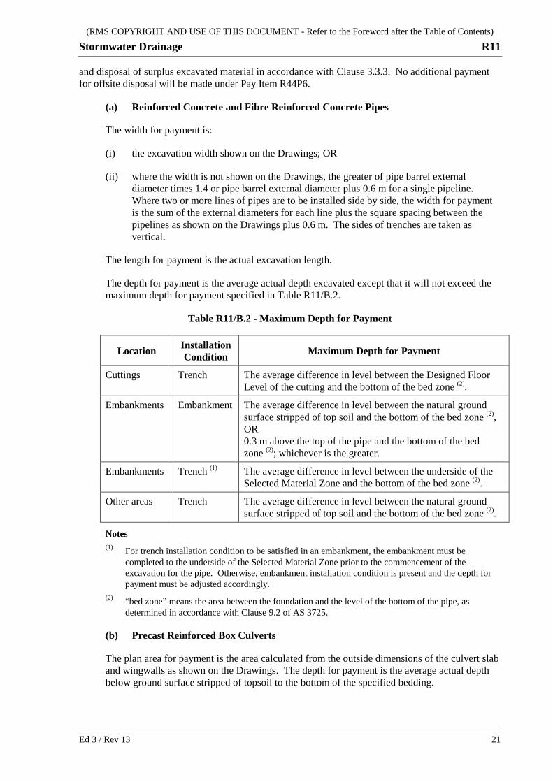
The depth for payment is the average actual depth excavated except that it will not exceed the maximum depth for payment specified in Table R11/B.2.
Table R11/B.2 - Maximum Depth for Payment
Location Installation Condition Maximum Depth for Payment
Cuttings Trench The average difference in level between the Designed Floor Level of the cutting and the bottom of the bed zone (2).
Embankments Embankment The average difference in level between the natural ground surface stripped of top soil and the bottom of the bed zone (2), OR 0.3 m above the top of the pipe and the bottom of the bed zone (2); whichever is the greater.
Embankments Trench (1) The average difference in level between the underside of the Selected Material Zone and the bottom of the bed zone (2).
Other areas Trench The average difference in level between the natural ground surface stripped of top soil and the bottom of the bed zone (2).
Notes (1) For trench installation condition to be satisfied in an embankment, the embankment must be
completed to the underside of the Selected Material Zone prior to the commencement of the excavation for the pipe. Otherwise, embankment installation condition is present and the depth for payment must be adjusted accordingly.
(2) “bed zone” means the area between the foundation and the level of the bottom of the pipe, as determined in accordance with Clause 9.2 of AS 3725.
(b) Precast Reinforced Box Culverts
The plan area for payment is the area calculated from the outside dimensions of the culvert slab and wingwalls as shown on the Drawings. The depth for payment is the average actual depth below ground surface stripped of topsoil to the bottom of the specified bedding.
(RMS COPYRIGHT AND USE OF THIS DOCUMENT - Refer to the Foreword after the Table of Contents)
R11 Stormwater Drainage
22 Ed 3 / Rev 13
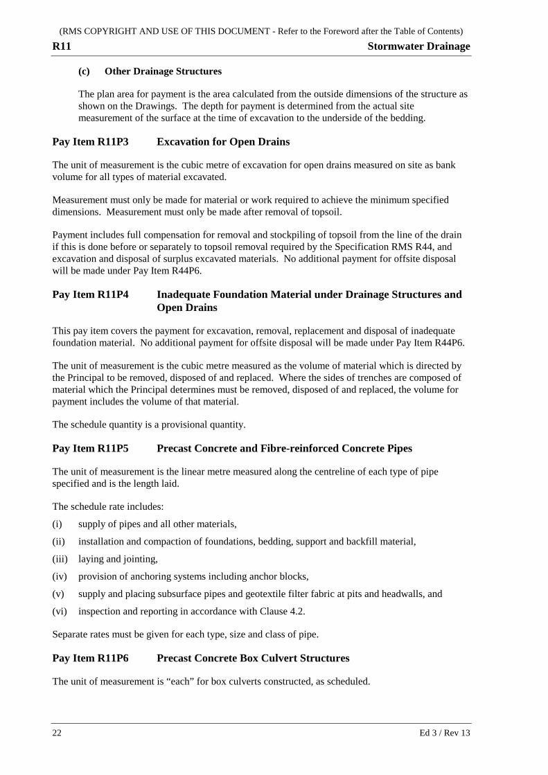
(c) Other Drainage Structures
The plan area for payment is the area calculated from the outside dimensions of the structure as shown on the Drawings. The depth for payment is determined from the actual site measurement of the surface at the time of excavation to the underside of the bedding.
Pay Item R11P3 Excavation for Open Drains
The unit of measurement is the cubic metre of excavation for open drains measured on site as bank volume for all types of material excavated.
Measurement must only be made for material or work required to achieve the minimum specified dimensions. Measurement must only be made after removal of topsoil.
Payment includes full compensation for removal and stockpiling of topsoil from the line of the drain if this is done before or separately to topsoil removal required by the Specification RMS R44, and excavation and disposal of surplus excavated materials. No additional payment for offsite disposal will be made under Pay Item R44P6.
Pay Item R11P4 Inadequate Foundation Material under Drainage Structures and Open Drains
This pay item covers the payment for excavation, removal, replacement and disposal of inadequate foundation material. No additional payment for offsite disposal will be made under Pay Item R44P6.
The unit of measurement is the cubic metre measured as the volume of material which is directed by the Principal to be removed, disposed of and replaced. Where the sides of trenches are composed of material which the Principal determines must be removed, disposed of and replaced, the volume for payment includes the volume of that material.
The schedule quantity is a provisional quantity.
Pay Item R11P5 Precast Concrete and Fibre-reinforced Concrete Pipes
The unit of measurement is the linear metre measured along the centreline of each type of pipe specified and is the length laid.
The schedule rate includes:
(i) supply of pipes and all other materials,
(ii) installation and compaction of foundations, bedding, support and backfill material,
(iii) laying and jointing,
(iv) provision of anchoring systems including anchor blocks,
(v) supply and placing subsurface pipes and geotextile filter fabric at pits and headwalls, and
(vi) inspection and reporting in accordance with Clause 4.2.
Separate rates must be given for each type, size and class of pipe.
Pay Item R11P6 Precast Concrete Box Culvert Structures
The unit of measurement is “each” for box culverts constructed, as scheduled.
(RMS COPYRIGHT AND USE OF THIS DOCUMENT - Refer to the Foreword after the Table of Contents)
Stormwater Drainage R11
Ed 3 / Rev 13 23
The schedule rate includes supply of all materials, preparation of foundations (including removal, disposal and replacement of material required by Clause 3.6), plain concrete, placing the invert and precast units (including mortar pads, temporary bracing and other protective measures), link slabs (if applicable), jointing (including connections and transverse sealing membrane), backfilling, compaction, inspecting and reporting. The rate excludes inlet and outlet structures.
Separate rates must be given for each type, size, cell configuration and length of box culverts.
Pay Item R11P7 Drainage Structures Other Than Pipes and Box Culverts
The unit of measurement is “each” for drainage structures constructed, as scheduled. The unit of the structure includes associated structural works, for example, a headwall unit must include the wingwalls, apron and cut off walls.
The schedule rate includes supply of all materials, all necessary excavations (unless there is a separate pay item for excavation), preparation of foundations, plain concrete, bedding, construction, installation, jointing (including connections), backfilling, compaction, inspecting and reporting.
Pay Item R11P8 Concrete Lining of Open Drains
The unit of measurement is the square metre of concrete lining.
The area is calculated from the slope area of the actual work completed.
The schedule rate includes preparation, supply, placement, curing and protection of concrete, additives and jointing materials, and all finishing work.
(RMS COPYRIGHT AND USE OF THIS DOCUMENT - Refer to the Foreword after the Table of Contents)
R11 Stormwater Drainage
24 Ed 3 / Rev 13
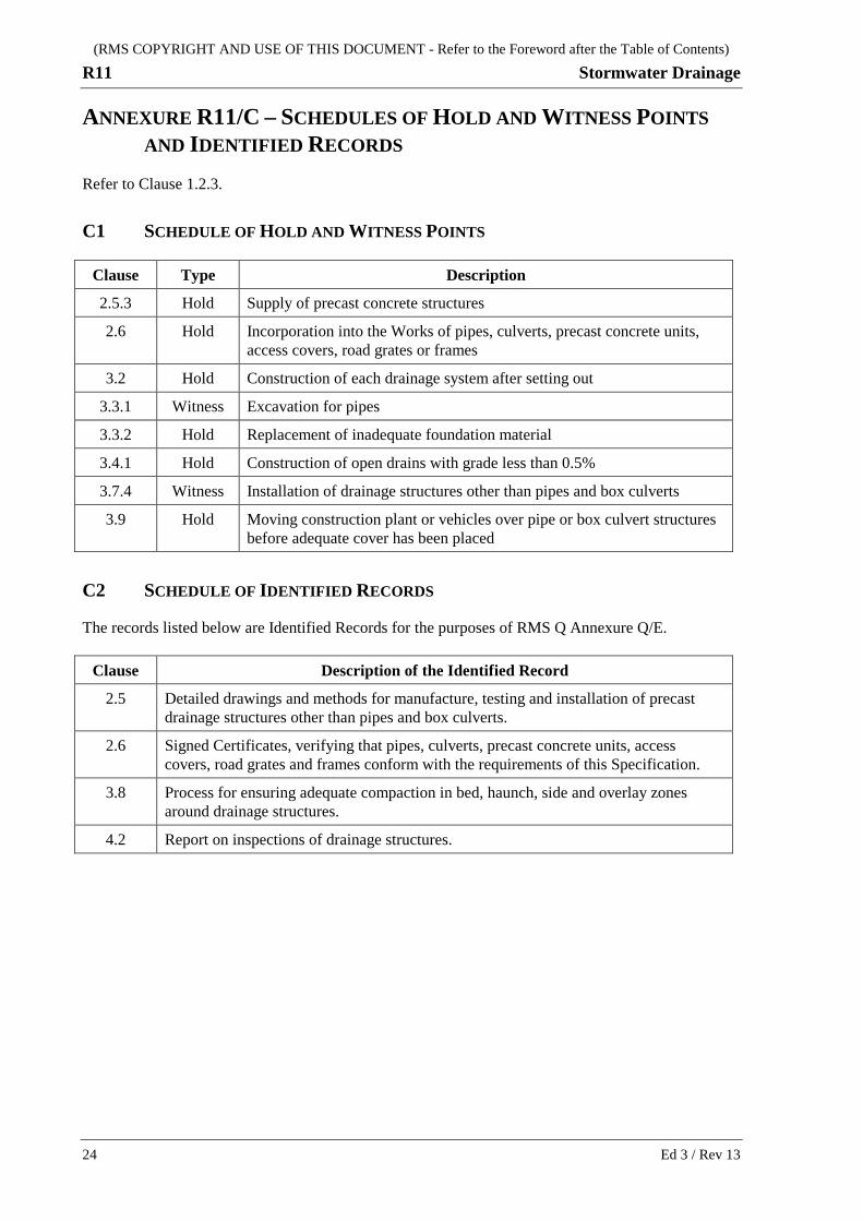
ANNEXURE R11/C – SCHEDULES OF HOLD AND WITNESS POINTS AND IDENTIFIED RECORDS
Refer to Clause 1.2.3.
C1 SCHEDULE OF HOLD AND WITNESS POINTS
Clause Type Description
2.5.3 Hold Supply of precast concrete structures
2.6 Hold Incorporation into the Works of pipes, culverts, precast concrete units, access covers, road grates or frames
3.2 Hold Construction of each drainage system after setting out
3.3.1 Witness Excavation for pipes
3.3.2 Hold Replacement of inadequate foundation material
3.4.1 Hold Construction of open drains with grade less than 0.5%
3.7.4 Witness Installation of drainage structures other than pipes and box culverts
3.9 Hold Moving construction plant or vehicles over pipe or box culvert structures before adequate cover has been placed
C2 SCHEDULE OF IDENTIFIED RECORDS
The records listed below are Identified Records for the purposes of RMS Q Annexure Q/E.
Clause Description of the Identified Record
2.5 Detailed drawings and methods for manufacture, testing and installation of precast drainage structures other than pipes and box culverts.
2.6 Signed Certificates, verifying that pipes, culverts, precast concrete units, access covers, road grates and frames conform with the requirements of this Specification.
3.8 Process for ensuring adequate compaction in bed, haunch, side and overlay zones around drainage structures.
4.2 Report on inspections of drainage structures.
(RMS COPYRIGHT AND USE OF THIS DOCUMENT - Refer to the Foreword after the Table of Contents)
Stormwater Drainage R11
Ed 3 / Rev 13 25
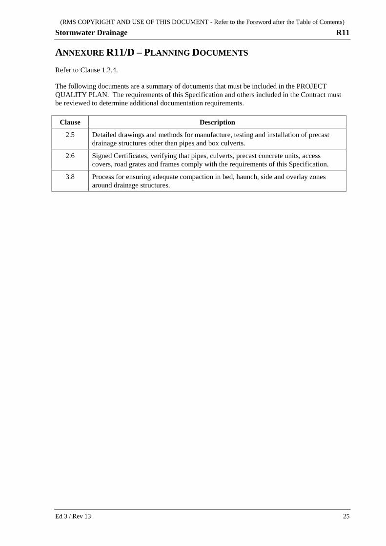
ANNEXURE R11/D – PLANNING DOCUMENTS Refer to Clause 1.2.4.
The following documents are a summary of documents that must be included in the PROJECT QUALITY PLAN. The requirements of this Specification and others included in the Contract must be reviewed to determine additional documentation requirements.
Clause Description
2.5 Detailed drawings and methods for manufacture, testing and installation of precast drainage structures other than pipes and box culverts.
2.6 Signed Certificates, verifying that pipes, culverts, precast concrete units, access covers, road grates and frames comply with the requirements of this Specification.
3.8 Process for ensuring adequate compaction in bed, haunch, side and overlay zones around drainage structures.

(RMS COPYRIGHT AND USE OF THIS DOCUMENT - Refer to the Foreword after the Table of Contents)
R11 Stormwater Drainage
26 Ed 3 / Rev 13
ANNEXURES R11/E TO R11/K – (NOT USED)
ANNEXURE R11/L – MINIMUM FREQUENCY OF TESTING Refer to Clause 1.2.5. Claus
e Characteristic Analysed Test Method Minimum Frequency of Testing
2.2 Precast concrete pipes: In accordance with AS 4058
In accordance with AS 4058
2.3 Fibre reinforced concrete pipes: In accordance with AS 4139
In accordance with AS 4139
2.7 Select fill in bed and haunch zones:
particle size distribution RMS T201 - One per 50 m3 or part thereof prior to placement
plasticity RMS T109 - One per 100 m3 or part thereof prior to placement
2.7 Select fill in side and overlay zones:
particle size distribution RMS T201 - One per 100 m3 or part thereof prior to placement
plasticity RMS T109 - One per 200 m3 or part thereof prior to placement
Compaction:
3.8(a)
3.8(b)
3.8(c)
3.8(d)
Selected Material Zone
foundations and trench bases
surface of excavated open drains
other fill material
RMS T166 - In accordance with the
requirements of Specification RMS Q Annexure L3
(RMS COPYRIGHT AND USE OF THIS DOCUMENT - Refer to the Foreword after the Table of Contents)
Stormwater Drainage R11
Ed 3 / Rev 13 27
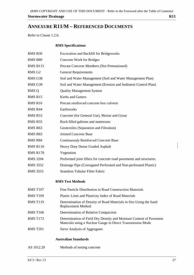
ANNEXURE R11/M – REFERENCED DOCUMENTS Refer to Clause 1.2.6.
RMS Specifications
RMS B30 Excavation and Backfill for Bridgeworks
RMS B80 Concrete Work for Bridges
RMS B115 Precast Concrete Members (Not Pretensioned)
RMS G2 General Requirements
RMS G38 Soil and Water Management (Soil and Water Management Plan)
RMS G39 Soil and Water Management (Erosion and Sediment Control Plan)
RMS Q Quality Management System
RMS R15 Kerbs and Gutters
RMS R16 Precast reinforced concrete box culverts
RMS R44 Earthworks
RMS R53 Concrete (for General Use), Mortar and Grout
RMS R55 Rock filled gabions and mattresses
RMS R63 Geotextiles (Separation and Filtration)
RMS R83 Jointed Concrete Base
RMS R84 Continuously Reinforced Concrete Base
RMS R116 Heavy Duty Dense Graded Asphalt
RMS R178 Vegetation
RMS 3204 Preformed joint fillers for concrete road pavements and structures.
RMS 3552 Drainage Pipe (Corrugated Perforated and Non-perforated Plastic)
RMS 3553 Seamless Tubular Filter Fabric
RMS Test Methods
RMS T107 Fine Particle Distribution in Road Construction Materials
RMS T109 Plastic Limit and Plasticity Index of Road Materials
RMS T119 Determination of Density of Road Materials in Situ Using the Sand Replacement Method
RMS T166 Determination of Relative Compaction
RMS T173 Determination of Field Dry Density and Moisture Content of Pavement Materials using a Nuclear Gauge in Direct Transmission Mode
RMS T201 Sieve Analysis of Aggregates
Australian Standards
AS 1012.20 Methods of testing concrete
(RMS COPYRIGHT AND USE OF THIS DOCUMENT - Refer to the Foreword after the Table of Contents)
R11 Stormwater Drainage
28 Ed 3 / Rev 13
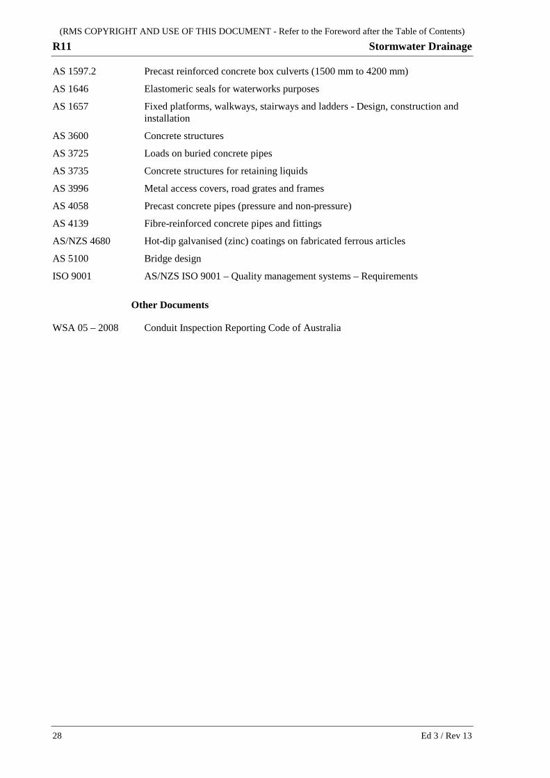
AS 1597.2 Precast reinforced concrete box culverts (1500 mm to 4200 mm)
AS 1646 Elastomeric seals for waterworks purposes
AS 1657 Fixed platforms, walkways, stairways and ladders - Design, construction and installation
AS 3600 Concrete structures
AS 3725 Loads on buried concrete pipes
AS 3735 Concrete structures for retaining liquids
AS 3996 Metal access covers, road grates and frames
AS 4058 Precast concrete pipes (pressure and non-pressure)
AS 4139 Fibre-reinforced concrete pipes and fittings
AS/NZS 4680 Hot-dip galvanised (zinc) coatings on fabricated ferrous articles
AS 5100 Bridge design
ISO 9001 AS/NZS ISO 9001 – Quality management systems – Requirements
Other Documents
WSA 05 – 2008 Conduit Inspection Reporting Code of Australia