Embed Size (px)
Citation preview

Edition 3 / Revision 3 ROADS AND MARITIME SERVICES February 2012
ROADS AND MARITIME SERVICES (RMS)
QA SPECIFICATION R132
SAFETY BARRIER SYSTEMS
NOTICE
This document is a Roads and Maritime Services QA Specification. It has been developed for use with roadworks and bridgeworks contracts let by Roads and Maritime Services or by local councils in NSW. It is not suitable for any other purpose and must not be used for any other purpose or in any other context.
Copyright in this document belongs to Roads and Maritime Services.
REVISION REGISTER
Ed/Rev Number
Clause Number Description of Revision Authorised
By Date
Ed 1/Rev 1 First Issued GM, CMS Jan 91
Ed 1/Rev 2 Clause numbers and lists have been restructured to suit the new format.
GM, PSP; J Woodward
24.03.95
Ed 2/Rev 0 All Specification Number changed from RTA R69.
Converted to MS Word 6.0c. References to RTA Specifications changed.
Completely rewritten.
GM, PSP 16.07.96
Ed 2/Rev 1 Various
2.1
2.5
Editorial changes.
Deleted requirement for steel posts to be marked for identification.
Deleted reference to American Douglas Fir.
GM, PSP (J Woodward)
18.11.96
Ed 2/Rev 2 Revisions to Edition 2
New clause GM, RNIC (J Woodward)
18.02.97
Ed 2/Rev 3 1.2, 2.2, 2.3.1, 4.1.1
AS 1650 replaced by AS/NZS 4680 GM, RNIC 16.07.99
Annex R132/6
New annexure listing Identified Records
Ed 3/Rev 0 Notice RTA PO Box and Fax numbers updated GM, IC 16.06.09
Global Text revised to direct imperative style. ”Superintendent” replaced by “Principal”. “shall” replaced by “must”. Reformatting and minor editing to clarify intent. Some clauses moved to Annexures.
Foreword Foreword, incorporating copyright clause, added.
Ed 3/Rev 0 Guide Notes Notes on the use of Ed 3/Rev 0 added.

ii
Ed/Rev Number
Clause Number Description of Revision Authorised
By Date
(cont’d) Global “terminal” changed to “end treatment”.
1.1 Scope clarified to exclude pedestrian safety barriers.
1.2.4 Definitions of “you” and “your” added.
Definitions for “List of accepted road safety barrier products”, “Crash cushion”, “RTA requirements” and “Joint” added.
Definitions for “Delineation unit”, “Device” and “Leading end treatment” revised.
1.4 Requirements for shielding unprotected barrier ends modified. HOLD POINT added.
Requirements for temporary road safety barrier systems and stacking of new or surplus materials or components added.
2.1 New clause on road safety barrier systems standards.
2.4.1 New clause on steel properties of various components.
2.4.2 New clause on bolts, nuts and washers requirements.
2.4.5 New clause on wire rope requirements.
2.5 Title: “….. and Mortar” added.
Requirements for concrete and mortar amended.
Requirement for submission of details of proposed steam curing added.
2.6 Retroreflective materials requirements relocated to clause 2.8. Requirements for plastic added.
2.7 New clause on aluminium requirements.
2.8 New clause on retroreflective materials requirements.
2.9 New clause on powder coating requirements.
2.10 Clause on timber re-numbered and revised.
3.1 “existing installed” added before “safety barrier system”.
3.3 Requirements for removal of redundant components added.
3.4 Clause reference for temporary stacking of materials on site added.
Ed 3/Rev 0 (cont’d)
4.1 Requirement for prevention of damage to utilities added.
iii
Ed/Rev Number
Clause Number Description of Revision Authorised
By Date
Field welding and flame cutting prohibited.
Requirement to record non standard materials or installations added.
4.1.2 Requirement for survey to comply with RTA G71 added.
Method of measurement of offsets for flares clarified.
Hold Point “Submission Details” re-worded to improve its clarity.
4.1.3 Requirement for provision of temporary end treatments added.
4.2.1 Entire clause re-arranged and re-worded to improve its clarity.
4th paragraph – “Cement may be added…” changed to “Do not add cement…”.
4.2.2(e) “and soil plates of gating leading end treatments and” added after “steel tubes”.
4.2.3 Prohibition of alternative post support for end treatments added.
Requirement for submission of proposals for extending safety barrier added.
4.4 New clause on wire rope safety barrier systems construction requirements
4.5.1 Method of measuring heights defined.
4.5.2 Requirements for shelf angles included.
4.5.3 Requirements for contraction joints and movement joints added.
4.6 Requirements for delineators for concrete barriers and slash markers at end treatments included.
4.7 Waste to be handled to G34/G35/G36 requirements added.
Ed 3/Rev 1 4.6 Drawing numbers for RTA Model Drawings for delineators corrected.
GM, IC 06.11.09
Guide Notes, 2.1
Reference to list in Annex M of RTA Model Drawings for public domain safety barrier systems inserted.
Ed 3/Rev 1 (cont’d)
Annex M AS 3610 added to list of Australian Standards.
List of RTA Model Drawings for public domain safety barrier systems added.
Ed 3/Rev 2 Pay Items P5 & P8
Clarification of extent of payment. GM, IC 15.11.10

iv
Ed/Rev Number
Clause Number Description of Revision Authorised
By Date
Ed 3/Rev 3 Guide Notes
Annex I
Notes on Annex I deleted.
Link to “Accepted Safety Barrier Products List” on internet inserted.
GM, IC (M.Andrew)
27.02.12

v
GUIDE NOTES (Not Part of Contract Document)
EDITION 2 REVISION 1
Edition 2 Revision 1 of Specification RTA R132 Safety Barrier Systems was an amplification of the earlier Specification RTA R69. The scope of RTA R69 was limited only to guardfence (i.e. post and rail safety barrier).
EDITION 3 REVISION 0
Overview
The changes in this revision includes updating the format to that currently in use for RMS roadworks specifications, updating the references, re-writing certain clauses to improve its clarity, and other changes to reflect current practice.
A major change is the requirement that all safety barrier systems must have been accepted by the RMS for use on classified roads. These fall into two categories: public domain systems and proprietary systems. For public domain systems, the manufacture, supply and construction must comply with the details shown on the RMS Model Drawings listed in Annexure R132/M. For proprietary systems, the manufacture, supply and construction must comply with the manufacturer’s recommendations, and with any RMS requirements for the product.
Any such RMS conditions attached to the acceptance of a product are made available to all persons using the product in NSW. Project Managers should not add any other requirements which do not comply with the intent of the acceptance process.
Clause 1.4
Clause 1.4 prohibits any safety barrier system without fully operational end treatments to be unshielded on a road open to traffic. There will be cases, for example on the near side of a dual carriageway, where this prohibition could be relaxed for trailing end treatments. A HOLD POINT is provided to allow the Contractor to submit proposals to vary the requirement, provided that the proposal is accompanied by a satisfactory risk assessment.
Note that delineation is required on bridge traffic barriers and concrete safety barriers. However, the method of attachment of delineators to bridge traffic barriers requires approval from Engineering Technology Bridge Engineering Branch.
Clause 4.2.1
Clause 4.2.1 has been modified to prohibit the addition of cement to the backfilling around the steel tubes at Posts Nos 1 and 2 in a Modified Eccentric Loader Terminal (MELT). Experience has shown that the bound soil can become airborne as a hard lump during an accident. For the same reason, it is very important to ensure that all concrete surrounding the buried part of a post or tube is monolithic and extends to the base of hole.
The RMS does not accept all the current provisions of AS/NZS 3845 “Road safety barrier systems” and this Standard is not referenced in this Specification. The Standard is currently under review and it is intended that updating RMS R132 will be considered when the new version of the Standard is issued.


Edition 3 / Revision 3 ROADS AND MARITIME SERVICES February 2012
QA SPECIFICATION R132
SAFETY BARRIER SYSTEMS Copyright – Roads and Maritime Services
IC-QA-R132
VERSION FOR: DATE:


Safety Barrier Systems R132
Ed 3 / Rev 3 i
CONTENTS
CLAUSE PAGE
FOREWORD .............................................................................................................................................. III RMS Copyright and Use of this Document ................................................................................. iii Revisions to Previous Version ..................................................................................................... iii Project Specific Changes ............................................................................................................. iii
1 GENERAL ........................................................................................................................................ 1 1.1 Scope .............................................................................................................................. 1 1.2 Structure of the Specification ......................................................................................... 1 1.3 Project Quality Plan ....................................................................................................... 3 1.4 Traffic Safety .................................................................................................................. 3
2 COMPONENTS FOR SAFETY BARRIER SYSTEMS ............................................................................. 4 2.1 Standards ........................................................................................................................ 4 2.2 Identification .................................................................................................................. 4 2.3 Certificates of Compliance ............................................................................................. 4 2.4 Steel ................................................................................................................................ 5 2.5 Concrete and Mortar ....................................................................................................... 6 2.6 Plastic ............................................................................................................................. 6 2.7 Aluminium ...................................................................................................................... 6 2.8 Retroreflective materials ................................................................................................ 6 2.9 Powder coating ............................................................................................................... 6 2.10 Timber ............................................................................................................................ 6
3 REMOVAL OF SAFETY BARRIER SYSTEMS ..................................................................................... 6 3.1 Removal - Scope ............................................................................................................. 6 3.2 Coordination and Sequence of Work ............................................................................. 7 3.3 Post Holes ....................................................................................................................... 7 3.4 Stacking or Disposing of Components ........................................................................... 7
4 CONSTRUCTION OF SAFETY BARRIER SYSTEMS ............................................................................ 7 4.1 Construction - General ................................................................................................... 7 4.2 Post and Rail Safety Barrier Systems ............................................................................. 9 4.3 Concrete Safety Barrier Systems .................................................................................. 10 4.4 Wire Rope Safety Barrier Systems ............................................................................... 11 4.5 Construction Tolerances ............................................................................................... 11 4.6 Delineation ................................................................................................................... 14 4.7 Waste ............................................................................................................................ 14
ANNEXURE R132/A – PROJECT SPECIFIC REQUIREMENTS .................................................................... 15
ANNEXURE R132/B – MEASUREMENT AND PAYMENT .......................................................................... 16 B1 Measurement and Payment........................................................................................... 16
ANNEXURE R132/C – SCHEDULES OF HOLD POINTS AND IDENTIFIED RECORDS .............................. 18 C1 Schedule of Hold Points ............................................................................................... 18 C2 Schedule of Identified Records .................................................................................... 18
ANNEXURE R132/D – PLANNING DOCUMENTS ...................................................................................... 19
ANNEXURE R132/E – (NOT USED) ......................................................................................................... 20
R132 Safety Barrier Systems
ii Ed 3 / Rev 3
ANNEXURE R132/F – COMPONENTS TO BE STACKED BY THE CONTRACTOR ........................................ 20
ANNEXURE R132/G – MATERIALS AND COMPONENTS TO BE SUPPLIED BY THE PRINCIPAL ................. 20
ANNEXURE R132/H – DOUBLE-SIDED SAFETY BARRIER SYSTEMS SUPPORTED ON STEEL POSTS IN MEDIANS ...................................................................................................................................... 21
ANNEXURE R132/I – LIST OF ACCEPTED SAFETY BARRIER PRODUCTS ................................................ 21
ANNEXURES R132/J TO R132/L – (NOT USED) ...................................................................................... 22
ANNEXURE R132/M – REFERENCE DOCUMENTS ................................................................................... 22
LAST PAGE OF THIS DOCUMENT IS .......................................................................................................... 25

Safety Barrier Systems R132
Ed 3 / Rev 3 iii
FOREWORD
RMS COPYRIGHT AND USE OF THIS DOCUMENT
Copyright in this document belongs to the Roads and Maritime Services.
When this document forms part of a contract
This document should be read with all the documents forming the Contract.
When this document does not form part of a contract
This copy is not a controlled document. Observe the Notice that appears on the first page of the copy controlled by RMS. A full copy of the latest version of the document is available on the RMS Internet website: www.rta.nsw.gov.au/doingbusinesswithus/specifications
REVISIONS TO PREVIOUS VERSION
This document has been revised from RMS Specification R132 Edition 3 Revision 2.
All revisions to the previous version (other than minor editorial and project specific changes) are indicated by a vertical line in the margin as shown here, except when it is a new edition and the text has been extensively rewritten.
PROJECT SPECIFIC CHANGES
Any project specific changes have been indicated in the following manner:
(a) Text which is additional to the base document and which is included in the Specification is shown in bold italics e.g. Additional Text.
(b) Text which has been deleted from the base document and which is not included in the Specification is shown struck out e.g. Deleted Text.


(RMS COPYRIGHT AND USE OF THIS DOCUMENT - Refer to the Foreword after the Table of Contents)
Ed 3 / Rev 3 1
RMS QA SPECIFICATION R132
SAFETY BARRIER SYSTEMS
1 GENERAL
1.1 SCOPE
This Specification sets out the requirements for the construction of new safety barrier systems, including safety barriers, end treatments, transitions and delineation, and the removal of existing safety barrier systems. It does not include the construction of clear areas behind safety barrier systems.
Pedestrian fences have a road safety function but are not road safety barriers. Their construction is not included in the scope of this Specification.
1.2 STRUCTURE OF THE SPECIFICATION
This Specification includes a series of annexures that detail additional requirements.
1.2.1 Details of Work
Annexure R132/A outlines the types, locations and delineation details of safety barrier systems and devices to be removed, and supplied and constructed, in accordance with this Specification.
1.2.2 Measurement and Payment
The method of measurement and payment must comply with Annexure R132/B.
1.2.3 Schedules of HOLD POINTS and Identified Records
The schedules list the HOLD POINTS that must be observed. Refer to Specification RMS Q for the definition of HOLD POINTS.
The records listed in Annexure R132/C are Identified Records for the purposes of RMS Q Annexure Q/E.
1.2.4 Reference Documents
Unless otherwise specified the applicable issue of a reference document, other than an RMS Specification, must be the issue current at the date one week before the closing date for tenders, or where no issue is current at that date, the most recent issue.
Standards, specifications and test methods are referred to in abbreviated form (e.g. AS 2350). For convenience, the full titles are given in Annexure R132/M.
1.2.4 Reference Documents and Definitions
The terms “you” and “your” mean “the Contractor” and “the Contractor’s” respectively.

(RMS COPYRIGHT AND USE OF THIS DOCUMENT - Refer to the Foreword after the Table of Contents)
R132 Safety Barrier Systems
2 Ed 3 / Rev 3
“RMS” refers to the Roads and Maritime Services.
The definitions given below will apply to this Specification.
(a) Crash cushion: See “end treatment”.
(b) Delineation unit: Delineation refers to treatments which enhance the visual definition of the roadway operating area. In the context of this Specification, a delineation unit is either: - a retroreflector fixed to a mounting plate attached to a road safety barrier, or - a retroreflector attached to, or placed immediately in front of, an end treatment.
(c) Departure end treatment: An end treatment for a safety barrier system of a type which is used only at the departure end with respect to the direction of flow of traffic.
(d) Device: A generic term used to refer to a safety barrier, an end treatment or a transition. In this context, a device is usually part of a safety barrier system.
The term is also used to describe a type of retroreflector. Refer to AS/NZS 1906.2 for further information.
(e) End treatment: A device to protect vehicle occupants from injury in an impact with the end of a safety barrier. End treatments can be either leading end treatments or departure end treatments.
(f) Joint: Three types of joints are used in concrete road safety barriers:
Construction joints are provided for the convenience of construction and their presence must not impair the load-carrying capacity and serviceability of the structures.
Contraction joints are joints provided to control shrinkage cracking without impairing the strength of the structure.
Movement joints (also called expansion or isolation joints) are provided between portions of a structure or between adjacent structures to permit relative movements between the portions or structures on either sides of the joints.
Reinforcing steel usually continues through construction and contraction joints but not through movement joints. Movement joints may include dowels or other items designed to limit relative movements in some directions.
(g) Leading end treatment: An end treatment at the end of a safety barrier which faces oncoming traffic.
(h) List of accepted safety barrier products: The list of road safety barrier products that have been accepted by the RMS for use on classified roads. A copy of this list is included in this Specification as Annexure R132/I. The date of issue of this list is shown at the head of the list.
(i) Manufacturer’s recommendations: The specification, installation manual and drawings for a specific proprietary safety barrier system or device, prepared by or for the manufacturer, detailing the components, the system or device, and the methods and/or procedures for installation.
(j) Nested rails: Two or more steel rails erected together (one inside the other) to increase stiffness. Nested rails share bolts.

(RMS COPYRIGHT AND USE OF THIS DOCUMENT - Refer to the Foreword after the Table of Contents)
Safety Barrier Systems R132
Ed 3 / Rev 3 3
(k) Safety barrier system: A longitudinal structure whose prime purpose is to restrain and/or redirect in a controlled manner vehicles which are out of control. A safety barrier system includes one or more safety barriers with associated end treatments and transitions.
(l) RMS requirements: When used in relation to a proprietary products, this phrase refers to any specific requirements for the product included in the RMS’ acceptance advice to the supplier. It is a requirement of each acceptance that these requirements be made known to any purchaser of the product for use on the NSW classified road system.
(m) Safety barrier: That part of a safety barrier system other than end treatments and transitions.
(n) Terminal: See “end treatment”.
(o) Transition: A connecting device to provide effective continuity of the protection offered by a safety barrier between safety barriers of different properties or dimensions. The part of a safety barrier system with varying properties such as stiffness and dimensions, between and linking safety barriers with different properties or dimensions. A transition may also link or connect a safety barrier to a fixture.
1.3 PROJECT QUALITY PLAN
The PROJECT QUALITY PLAN must include each of the documents and requirements listed in Annexure R132/D and must be implemented.
If the Contract does not require you to implement a PROJECT QUALITY PLAN, the documents listed in Annexure R132/D must be submitted to the Principal for consideration at least 5 working days prior to work commencing and must be implemented.
In all cases where this Specification refers to the manufacturer’s recommendations, these must be included in the PROJECT QUALITY PLAN along with any applicable RMS requirements.
1.4 TRAFFIC SAFETY
On a road open to traffic, you must implement a suitable traffic control plan, conforming with Specification RMS G10, to shield any partly dismantled or partly constructed safety barrier system or any safety barrier system without fully operational end treatments.
Should you wish to vary this requirement, you must provide to the Principal full details of your proposals to protect the passing traffic. Your submission must include a risk assessment.
HOLD POINT
Process Held: On a road open to traffic, allowing any safety barrier system which does not have fully operational end treatments to be unshielded.
Submission Details: Submit, at least three clear working days before the proposed exposure of the safety barrier system without fully operational end treatments, full details of your proposals together with a risk assessment of your proposals.
Release of Hold Point: The Principal will examine the proposals and the associated risk assessment before releasing the Hold Point.

(RMS COPYRIGHT AND USE OF THIS DOCUMENT - Refer to the Foreword after the Table of Contents)
R132 Safety Barrier Systems
4 Ed 3 / Rev 3
On a road open to traffic, you must consider the locations of any temporary stacks of new or surplus materials or components when preparing your traffic control plan in accordance with RMS G10.
If stacks are located behind a serviceable road safety barrier system, the clear space between the road safety barrier system and the stack must allow for the dynamic deflection of the system and be at sufficient distance from the ends of the system to allow the proper functioning of the end treatments.
2 COMPONENTS FOR SAFETY BARRIER SYSTEMS
2.1 STANDARDS
Road safety barrier systems must comply with this Specification, the manufacturer’s recommendations along with any applicable RMS requirements, or the Drawings, as applicable.
All road safety barrier systems must have been accepted by the RMS for use on classified roads. Systems which have been so accepted are identified in Annexure R132/I. Their manufacture, supply and construction must comply with this Specification and:
(a) for public domain systems, the RMS Model Drawings listed in Annexure R132/M, or
(b) for proprietary systems, the manufacturer’s recommendations and any RMS requirements for the product,
as applicable.
If a particular safety barrier system is specified in the documents, an alternative to the specified system may be submitted for consideration by the Principal only if the alternative is accepted for use by the RMS for the same duty.
2.2 IDENTIFICATION
Mark on any steel rails, precast concrete segments and all plastic components of safety barrier systems and devices unobtrusively and permanently in text not more than 20 mm high, the following information:
(a) name of the manufacturer,
(b) batch number, or date of manufacture,
(c) strength grade and base metal thickness of the steel rails.
2.3 CERTIFICATES OF COMPLIANCE
At least seven (7) days prior to the proposed use of any materials and components supplied by you, submit to the Principal a signed statement certifying that the materials and components supplied comply with the requirements of this Specification. Support this statement with any relevant test reports and a copy of your verification checklist.
For galvanised steel components, include a manufacturer’s certificate of compliance certifying that the zinc coating mass is in accordance with the requirements of AS/NZS 4680, or, for components of proprietary safety barrier systems or devices, the manufacturer’s recommendations and any specified RMS requirements.

(RMS COPYRIGHT AND USE OF THIS DOCUMENT - Refer to the Foreword after the Table of Contents)
Safety Barrier Systems R132
Ed 3 / Rev 3 5
2.4 STEEL
2.4.1 Properties
Steel for the safety barriers must comply with the following:
Item Standard Requirement
Posts and blockouts AS/NZS 1594 Grade HA 300
Rails and rail stiffening pieces AS/NZS 1594 Grade HA 350, 2.7 mm base metal thickness unless shown otherwise on the Drawings
Strut and yoke AS 1163 and AS/NZS 3678
Tubes to be Grade C350. Yoke to be fabricated from Grade 250
Tubes for breakaway posts and soil plates
AS/NZS 1594 Grade HA 250
Base plates AS/NZS 3678 Grade 250
For proprietary products, steel must comply with the manufacturer’s recommendations and any RMS requirements.
2.4.2 Bolts, Nuts and Washers
Bolts, nuts and washers must comply with the details shown on the Drawings or the manufacturer’s recommendations and any RMS requirements.
2.4.3 Protective Treatment
Unless stated otherwise in the manufacturer’s recommendations and any RMS requirements for a specified proprietary safety barrier system or device, the surfaces of all ferrous metal components including posts, blockout pieces, rail elements, anchor plates, connectors and end treatment pieces must, after fabrication, be treated in accordance with AS 1627.4 or AS 1627.5, and finished by hot-dipped galvanising in accordance with AS/NZS 4680.
Galvanise all ferrous bolts, nuts and washers in accordance with AS 1214.
2.4.4 Curving Steel Rail
Where a radius of less than 45 m is specified, curve the steel rail at the factory. Carry out the curving operation in a manner that will not result in damage to the galvanising.
Clearly mark the curve radius in a permanent manner on the rear face of factory curved steel rail.
2.4.5 Wire Rope
Wire rope for post and rail end treatments must comply with AS 3569 and the details shown on the Drawings.
Wire rope used in proprietary systems must comply with the manufacturer’s recommendations and any applicable RMS requirements.

(RMS COPYRIGHT AND USE OF THIS DOCUMENT - Refer to the Foreword after the Table of Contents)
R132 Safety Barrier Systems
6 Ed 3 / Rev 3
2.5 CONCRETE AND MORTAR
Unless stated otherwise in the manufacturer’s recommendations and any applicable RMS requirements for a specified proprietary safety barrier system or device, or in Clause 4.3 for a concrete safety barrier system or device, the supply, placing and curing of concrete and mortar must comply with Specification RMS R53.
If steam curing is proposed, you must submit such details as part of your PROJECT QUALITY PLAN (refer Annexure R132/D).
2.6 PLASTIC
Plastic components must comply with the manufacturer’s recommendations and any applicable RMS requirements or the Drawings, as applicable.
2.7 ALUMINIUM
Sheet aluminium for delineator mounting plates for concrete road safety barriers must comply with AS/NZS 1734. Sheet must be alloy designation 1150 and anodised black in accordance with AS 1231. Anodising thickness grade must be AA15.
2.8 RETROREFLECTIVE MATERIALS
Retroreflective materials and combination of fluorescent/retroreflective materials must comply with AS 1906.1 or AS 1906.2 as appropriate. Colour testing for fluorescent material in daylight must be carried out by the double monochromator method.
2.9 POWDER COATING
Powder coating must comply with AS 4506.
2.10 TIMBER
Timber posts and blockout pieces where specified for terminals must be strength grade F8 Australian Slash Pine, preservative treated to hazard level H4 in accordance with AS 1604.1. Preservative treatment must be carried out using a vacuum/pressure autoclave process in a State Forests of NSW approved facility. The preservative used must not contain any chromium or arsenic. After treatment the timber must not be resawn, dressed, planed or otherwise have its original dimensions altered.
Address the hazards associated with timber preservatives and treated timber to comply with Specification RMS G21 or RMS G22 (as applicable to the Contract) and comply with WorkCover NSW Code of Practice for the Safe Handling of Timber Preservatives and Treated Timber.
3 REMOVAL OF SAFETY BARRIER SYSTEMS
3.1 REMOVAL - SCOPE
Removal of an existing installed safety barrier system includes:
(RMS COPYRIGHT AND USE OF THIS DOCUMENT - Refer to the Foreword after the Table of Contents)
Safety Barrier Systems R132
Ed 3 / Rev 3 7
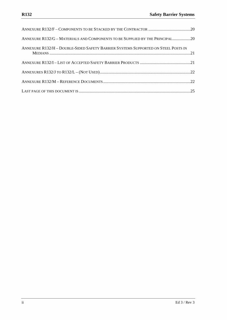
(a) dismantling or demolition of safety barriers, transitions and end treatments;
(b) extracting all posts, anchors and other in-ground components and materials;
(c) removing all components and waste materials from the site;
(d) cleaning, backfilling and mechanically compacting all excavations and holes formed by the extraction of posts, anchors and other in-ground components and materials; and
(e) stacking or disposing of components and waste materials.
3.2 COORDINATION AND SEQUENCE OF WORK
Where the safety barrier system being removed is on a road open to traffic, coordinate the removal with other work at the site to eliminate or minimise the exposure of an incomplete safety barrier system to traffic.
If practicable, commence removal of a safety barrier system from the departure end (remote from the approach of traffic), to improve traffic safety.
3.3 POST HOLES
Remove all redundant posts, anchors and other in-ground components by extraction or excavation. Following removal of the posts, clean out and backfill the holes. Backfilling and compaction of holes must proceed in 150 mm layers using similar materials to existing surrounding layers. Compact backfill to not less than the density of the surrounding layers.
3.4 STACKING OR DISPOSING OF COMPONENTS
Temporary stacking of materials on site must comply with Clause 1.4.
Do not damage any components to be retained by the Principal. Components to be retained by the Principal are listed in Annexure R132/F.
Deliver to and stack in an orderly manner at the locations stated in Annexure R132/F all components to be retained by the Principal.
All other surplus materials resulting from removal of safety barrier systems become your property, and must be removed from the site.
4 CONSTRUCTION OF SAFETY BARRIER SYSTEMS
4.1 CONSTRUCTION - GENERAL
Construction of safety barrier systems includes supply, delivery, handling and assembly of components and devices, setting out, and supply and installation of delineation.
Plan and execute your work in a manner that prevents damage to underground and above ground facilities such as utilities, services, structures, pavements, vegetation, etc.
Underground cables and ducts laid in the road safety barrier area shall be located prior to the erection of posts and all care must be taken not to damage such cables and ducts.

(RMS COPYRIGHT AND USE OF THIS DOCUMENT - Refer to the Foreword after the Table of Contents)
R132 Safety Barrier Systems
8 Ed 3 / Rev 3
The Principal will supply the components listed in Annexure R132/G and make them available to you at the locations and dates shown in Annexure R132/G.
Supply all other components and materials necessary to complete the work.
Unless stated otherwise in the manufacturer’s recommendations or shown on the Drawings, construct safety barrier systems with post supports with the posts vertical. Construct other safety barrier systems with the upright axis normal to the surface at the front of the barrier.
Construct the safety barrier system to form a smooth line vertically and horizontally, when viewed along the line of the system, free from humps, sags, or other irregularities, within tolerances.
Any component of a safety barrier system must not be welded or flame cut in the field under any circumstances. Welding and flame cutting in a workshop may be undertaken only where shown on the Drawings or in accordance with the manufacturer’s recommendations.
Record details of any non-standard materials or installation in your Quality Records.
4.1.1 Damage
Transport, handle and install components of safety barrier systems to avoid damage.
Where damage occurs, address the nonconformity in accordance with RMS Q.
After installation, components must not be left with splits, burrs, or sharp edges.
Repair any minor damage to galvanising in accordance with Appendix E of AS/NZS 4680 immediately, if practicable, and in any case within 24 hours, using at least two coats of a zinc-rich paint in accordance with AS/NZS 3750.9. Match the colour of the original surface either directly or by applying a further compatible treatment. Restrict this method of repair to individual areas not exceeding 40 cm2 for any point repaired and a total 0.1% of the surface area of any face for multiple repairs.
4.1.2 Setting Out
Survey work must comply with Specification RMS G71.
Install pegs in the ground (or mark with paint on hard ground) to mark the start and finish points and line of safety barriers, transitions and end treatments including the line of flare if applicable, before commencing construction. Measure offsets for flares from a line parallel to the adjacent lane line.
HOLD POINT
Process Held: Installation of safety barrier system.
Submission Details: Notification that the set out is in accordance with this Specification, the Drawings and the manufacturer’s recommendations, at least two full working days before the proposed commencement of installation of posts or assembly of components or devices whichever is earlier.
Release of Hold Point: The Principal will inspect the set out of the safety barriers before releasing the Hold Point.
(RMS COPYRIGHT AND USE OF THIS DOCUMENT - Refer to the Foreword after the Table of Contents)
Safety Barrier Systems R132
Ed 3 / Rev 3 9
4.1.3 Sequence of Work
Where a safety barrier system is being constructed on a road open to traffic, commence the work at the end closest to approaching traffic, except where the barrier connects at its departure end to a fixed object such as an existing barrier or the end of a bridge or tunnel.
Commission end treatments and transitions at the earliest practicable time. Provide temporary end treatments until the permanent treatment is complete.
4.2 POST AND RAIL SAFETY BARRIER SYSTEMS
4.2.1 Installation of Posts - Method Constraints
In ground conditions where you consider that installation of the posts by driving is unsuitable and that 400 mm diameter holes are necessary, you must promptly advise the Principal. Do not commence excavation of the 400 mm diameter holes until the Principal has approved the use of 400 mm diameter holes for installation of the posts.
Where the post is to be installed through a bound pavement layer, or when installing the posts for a Modified Eccentric Loader Terminal (MELT), or where directed by the Principal, carry out excavation or preboring to achieve a minimum hole diameter of 400 mm. Extend this hole diameter at least to within 300 mm of the level of the bottom of the installed post.
Locate each hole so that the post will be positioned centrally or towards the nearest traffic lane in the prebored hole.
Backfill around the steel tubes at Posts Nos 1 and 2 in a MELT must be clean, well graded, granular material. Do not add cement to this backfill.
Backfill around other posts must be clean, well graded, non-cementitious granular material or material obtained from excavating the post holes, provided that any different material types from within a hole are placed to match surrounding layers.
4.2.2 Installation of Posts - Acceptance Criteria
Installation of the posts must comply with the following requirements:
(a) The posts must be installed to the depth, line and spacing shown on the Drawings, and to the tolerances in Clause 4.5.
(b) The installation process must not cause any structural damage to the post, including any soil plates attached to the post.
(c) The installation must not cause any damage to the pavement beyond 100 mm from any part of any post, including any soil plate attached to the post.
(d) When a lateral force of 1 kN is applied in any direction within the top 200 mm of an installed post but before the rail is secured, the movement of the post at ground level must be not more than 3 mm.
(e) Backfill material around the steel tubes and soil plates of gating leading end treatments, and at Posts Nos 1 and 2 in a Modified Eccentric Loader Terminal (MELT), must be compacted to a minimum 95% relative compaction, measured in accordance with Test Method RMS T166;

(RMS COPYRIGHT AND USE OF THIS DOCUMENT - Refer to the Foreword after the Table of Contents)
R132 Safety Barrier Systems
10 Ed 3 / Rev 3
(f) The disturbed pavement or ground around a post must be trimmed and compacted to a dense, tight, smooth and sealed condition so that resistance to water penetration is similar to that of the adjacent surface.
4.2.3 Installation of Posts - Difficult Sites
If, in your opinion and for reasons outside your control, it is not feasible to install posts at the specified depth or location, submit to the Principal a proposal for a different method of supporting the safety barrier.
Alternative methods of support are not permitted for end treatments. You may however submit proposals for extending the safety barrier to a location where installation of the end treatment is feasible, or proposals for a different end treatment, for consideration by the Principal.
4.2.4 Orientation of Posts and Blockout Pieces
Install steel posts in a median facing the direction shown in Annexure R132/H.
Erect all C-section blockout pieces and steel posts with the open or concave face away from the ultimate direction of approach of traffic in the closest adjacent carriageway, unless shown otherwise on the Drawings.
4.2.5 Cables in End Treatments
Tension cables in end treatments by tightening the nuts at both ends of each cable to 50 Nm as part of the construction of end treatments.
Maintain tension in cables in end treatments until the Date of Completion, and keep the nuts at both ends tightened to 50 Nm.
4.3 CONCRETE SAFETY BARRIER SYSTEMS
4.3.1 General
Construct concrete safety barrier systems using either precast segments, by placing concrete using fixed forms or by slipforming, or a combination of these methods.
4.3.2 Preparatory Work on a Rigid Pavement (Concrete Surface)
Prior to constructing any part of a concrete safety barrier system on a concrete surface, you must:
(a) where you intend to use fixed forms or slipforming,
(i) fill each joint in the concrete surface on the line of the barrier with a bead of silicone sealant, extending the full width and a minimum of 100 mm outside both edges of the base of the safety barrier system, and forming a convex surface wholly proud of the plane of the pavement;
(ii) after filling each joint as in (i) above, debond the concrete surface on the line of the barrier by applying a uniform cover of curing compound at the rate of 0.3 litre/m2, extending the full width and a minimum of 100 mm outside both edges of the base of the safety barrier system; and

(RMS COPYRIGHT AND USE OF THIS DOCUMENT - Refer to the Foreword after the Table of Contents)
Safety Barrier Systems R132
Ed 3 / Rev 3 11
(b) where you intend to use precast safety barrier system segments, after debonding the concrete surface, construct a (nominal) 15 mm cement mortar pad beneath and for the full width and length of the barrier system.
4.3.3 Joints in Concrete Placed In-situ
For concrete placed in-situ (either using fixed forms or by slipforming), control the shrinkage cracking by sawing or forming contraction joints. Contraction joints must be straight, square to the line of the barrier, 50 mm deep, and spaced at intervals of not more than 4.5 m along the barrier.
Where you elect to use sawing to control cracks, carry out sawing before uncontrolled cracking begins, and in any case, within 12 hours after placing the concrete.
Construct movement joints where shown on the Drawings. Movement joints must be straight, square to the line of the barrier, and 6 mm wide. Fill movement joints with a preformed joint filler complying with RMS 3204.
Where a concrete safety barrier system is cast or slipformed adjacent to or on top of a concrete pavement base layer, the same type of movement or contraction joint in the concrete base must be made in the safety barrier system and located to form a continuous joint through both structures.
4.4 WIRE ROPE SAFETY BARRIER SYSTEMS
Construct wire rope safety barrier systems in accordance with the manufacturer’s recommendations and any applicable RMS requirements. Unless otherwise shown in Annexure R132/A or on the Drawings, all posts must be coloured white.
Where the horizontal radius of the barrier is less than 200 metres or the vertical curvature at a sag is such that K (which is the length of the vertical curve measured in metres divided by the change in grade expressed as a %) is less than 30 metres, do not install a wire rope safety barrier system. Advise the Principal and request instructions on the type of safety barrier system to be constructed.
HOLD POINT
Process Held: Construction of a wire rope safety barrier system.
Submission Details: Proposed barrier system and a statement that horizontal and vertical curvatures are suitable, or, A statement that the horizontal curvature and/or vertical curvature at the site is/are unsuitable for a wire rope barrier system.
Release of Hold Point: The Principal will inspect the site and, if necessary, advise on the type of safety barrier system to be constructed before releasing the Hold Point.
4.5 CONSTRUCTION TOLERANCES
4.5.1 General
Unless stated otherwise in the manufacturer’s recommendations and any applicable RMS requirements for a particular proprietary safety barrier system or device, tolerances for construction of all safety barrier systems and devices must be as follows:

(RMS COPYRIGHT AND USE OF THIS DOCUMENT - Refer to the Foreword after the Table of Contents)
R132 Safety Barrier Systems
12 Ed 3 / Rev 3
(a) For height of barrier: ± 20 mm;
(b) For line of safety barrier system: ± 20 mm in plan view; and
(c) For departures from the upright axis (vertical or normal to the surface as applicable - see Clause 4.1): ± 15 mm at the top of the barrier.
The height must be measured vertically for systems constructed with vertical posts and normal to the road surface for other systems. Measure the height as follows:
(a) where the barrier is within the pavement, from the pavement surface;
(b) where the barrier is adjacent to the pavement, from the line of pavement crossfall extended to the barrier line; and
(c) for all other circumstances, as shown on the Drawings or as directed by the Principal.
Do not take into account local surface level deviations with maximum horizontal dimensions of 2 metres when measuring heights.
Do not exceed the height tolerance on the basis of producing a straight line along the top of a barrier.
In addition to the above, the tolerances stated in Clauses 4.5.2, 4.5.3 and 4.5.4 will also apply as appropriate.
4.5.2 Post and Rail Safety Barrier Systems
Refer to Figure R132.1.
The tolerance on post spacing must be plus or minus 25 mm. The deviation of the top of any post from a straight line joining the tops of the posts on either side must not exceed 10 mm, after allowing for horizontal and vertical curves
When the barrier is erected, the maximum combined tolerance for rotation in plan of the post and blockout piece must be 30 mm, except that this may be increased to 60 mm for an isolated post where separated by at least 8 metres from another post with a rotation in plan beyond 30 mm.
Where the rail is supported on a shelf angle, there must be no horizontal or vertical gap between the rail and the inner faces of the shelf angle.

(RMS COPYRIGHT AND USE OF THIS DOCUMENT - Refer to the Foreword after the Table of Contents)
Safety Barrier Systems R132
Ed 3 / Rev 3 13
Figure R132.1
4.5.3 Concrete Safety Barrier Systems
Face steps, including at construction joints, must not exceed the limits in Table 3.4.2 in AS 3610 for Class 3 surface finish, viz 5 mm for 100% of readings and 3 mm for 80% of readings.
The deviation from any specified plan or cross-sectional dimension must not exceed 1/200 times the specified dimension, or 5 mm, whichever is the greater.
The deviation of any point from a straight line joining any two points on top of the barrier must not exceed 1/250 times the length of the line or 10 mm, whichever is the greater, after allowing for horizontal and vertical curves.
Surface undulations on the faces of a barrier must not exceed the limits in Table 3.4.2 in AS 3610 for Class 3 surface finish, viz:
Length of Straight Edge
Percent of Readings
80% 100%
300 mm 3 mm 4 mm
1,500 mm 5 mm 7 mm
Any offset between the line of an existing joint in a concrete pavement base layer and the line of the corresponding joint in the concrete safety barrier system placed in-situ adjacent to or on top of the concrete pavement base layer must not exceed 15 mm at the bottom of the barrier.
The line of a transverse joint must not deviate by more than 10 mm from a line comprising a series of contiguous straight lines on the surfaces of the barrier. Contraction joints must not deviate more than 5° from the square to the line of the barrier and be 50 (± 5) mm deep. Movement joints must not

(RMS COPYRIGHT AND USE OF THIS DOCUMENT - Refer to the Foreword after the Table of Contents)
R132 Safety Barrier Systems
14 Ed 3 / Rev 3
deviate from the square to the line of the barrier by more than 5° and the width must be within – 0, + 2 mm of the specified width.
4.5.4. Wire Rope Safety Barrier Systems
Comply with the tolerances specified in Clause 4.5.1, the manufacturer’s recommendations and any applicable RMS requirements.
4.6 DELINEATION
Supply delineation units and mount them on safety barrier systems at locations and spacings as shown on the Drawings or as detailed in Annexure R132/A.
Except on a concrete safety barrier, arrange delineation units so that drivers approaching from either direction will see only:
(a) red retro-reflectors on their left;
(b) white retro-reflectors on their right on two-way carriageways; and
(c) yellow retro-reflectors on their right on one-way carriageways and medians separating traffic in opposing directions.
The retro-reflectors must be either discrete device type retro-reflectors or sheeting type retroreflectors complying with AS 1906.2.
For post and rail safety barriers, delineation units are as shown on RMS Model Drawing MD.R132.E01.A.1.
Fix slash markers G9-257(L) or G9-257(R) as appropriate to end treatments for post and rail safety barriers. Remove any manufacturer’s labels or markings.
Details of the slash markers may be found at www.rmservices.nsw.gov.au/cgi-bin/index.cgi?action=searchtrafficsigns.form.
Sheeting must be Class 1 in areas without roadway lighting and Class 1W in areas which are lit.
Retro-reflectors on concrete safety barriers must be as shown on RMS Model Drawing MD.R132.E02.A.
The combination fluorescent/retro-reflective sheeting must comply with AS 1906.1 for Class 1 in areas without roadway lighting and for Class 1W in areas which are lit.
Fasten the base plate to the top of the barrier using an epoxy adhesive formulated for the purpose. Use the adhesive in accordance with the manufacturer’s recommendations and any applicable RMS requirements.
Safety barrier delineators are to be spaced to comply with AS 1742.2 or at 20 metre centres, whichever gives the closer spacing.
4.7 WASTE
Recycle, reuse or dispose of all surplus material, rubbish and other debris in accordance with the requirements of Specification RMS G34M, RMS G35 or RMS G36 (as applicable to the Contract).
(RMS COPYRIGHT AND USE OF THIS DOCUMENT - Refer to the Foreword after the Table of Contents)
Safety Barrier Systems R132
Ed 3 / Rev 3 15
ANNEXURE R132/A – PROJECT SPECIFIC REQUIREMENTS Refer to Clause 1.2.1.
The types, locations of safety barrier systems and devices to be removed and constructed, and the locations of delineation units are described in the table below or the Drawings.
Safety Barrier System Details Delineation Units
Type Locations Locations
Type (Safety Barriers, End Treatments, and Transitions) *
P /
NP
* R
/ I
* S
ide
L
/ R
/ M
From (km)
To (km)
Carriage-way
Left (km)
Right (km)
*Note: P: Patented NP: Non patented
R: Remove I: Install
L: Left R: Right M: Middle
(RMS COPYRIGHT AND USE OF THIS DOCUMENT - Refer to the Foreword after the Table of Contents)
R132 Safety Barrier Systems
16 Ed 3 / Rev 3
ANNEXURE R132/B – MEASUREMENT AND PAYMENT
B1 MEASUREMENT AND PAYMENT
Payment for the activities associated with completing the work detailed in this Specification is made in accordance with the following Pay Items.
A lump sum price for any of these items will not be accepted.
If any item for which a quantity of work is listed in the Schedule of Rates has not been priced by you, it will be deemed that due allowance has been made in the prices of other items for the cost of the activity which has not been priced.
The rate for each Pay Item for construction of safety barriers, end treatments and transitions includes the supply and installation of delineation.
No additional payment will be made for royalties or the like payable in connection with any product supplied by you in the performance of the Contract.
No additional payment will be made for disposal or recycling of surplus material.
No additional payment will be made for laps in barrier rails or nested rails when measuring length for payment.
Pay Item R132P1 Removal of Safety Barriers
The unit of measurement for Pay Item R132P1 is the linear metre calculated from the actual length of safety barrier removed not including end treatments or transitions.
Pay Item R132P2 Removal of End Treatments and Transitions
The unit of measurement for Pay Item R132P2 is “each” end treatment or transition removed.
Pay Item R132P3 Construction of Post and Rail Safety Barriers
The unit of measurement for Pay Item R132P3 is the linear metre calculated from the actual length of barrier constructed not including end treatments or transitions.
R132P3.1 Near side (single sided) post and rail barriers
R132P3.2 Median (double sided) post and rail barriers
Pay Item R132P4 Post Holes at 400 mm Diameter
The unit of measurement for Pay Item R132P4 is “each” 400 mm diameter post hole required and excavated or bored. The schedule quantity for Item R132P4 is a provisional quantity.
Pay Item R132P5 Construction of Wire Rope Safety Barrier Systems
The unit of measurement for Pay Item R132P5 is the linear metre calculated from the actual length of barrier system constructed including wire rope anchor blocks.

(RMS COPYRIGHT AND USE OF THIS DOCUMENT - Refer to the Foreword after the Table of Contents)
Safety Barrier Systems R132
Ed 3 / Rev 3 17
Pay Item R132P6 Construction of Plastic Safety Barriers
The unit of measurement for Pay Item R132P6 is the linear metre calculated from the actual length of plastic barrier constructed not including end treatments or transitions.
Pay Item R132P7 Construction of Concrete Safety Barrier Systems
The unit of measurement for Pay Item R132P7 is the linear metre calculated from the actual length of concrete safety barrier system including end treatments constructed from concrete and transitions supplied and constructed.
The schedule rate includes preparation of the existing surface and incorporation of any voids or inserts.
Pay Item R132P8 Construction of End Treatments
The unit of measurement for Pay Item R132P8 is “each” end treatment supplied and constructed, but not including concrete end treatments which are included in Pay Item R132P7 or wire rope anchor blocks which are included in Pay Item R132P5.
Pay Item R132P9 Construction of Transitions
The unit of measurement for Pay Item R132P9 is “each” transition supplied and constructed, but not including concrete transitions which are included in Pay Item R132P7.

(RMS COPYRIGHT AND USE OF THIS DOCUMENT - Refer to the Foreword after the Table of Contents)
R132 Safety Barrier Systems
18 Ed 3 / Rev 3
ANNEXURE R132/C – SCHEDULES OF HOLD POINTS AND IDENTIFIED RECORDS
Refer to Clause 1.2.3.
C1 SCHEDULE OF HOLD POINTS
Clause Description
1.4 Exposure of traffic to a barrier without operational end treatments.
4.1.2 Setting out.
4.4 Construction of a wire rope safety barrier system.
C2 SCHEDULE OF IDENTIFIED RECORDS
The records listed below are Identified Records for the purposes of RMS Q Annexure Q/E.
Clause Description of Identified Record
2.2 Statement that the materials and components to be used comply with the requirements of this Specification, supported by test reports and a copy of your verification checklist.
4.1 Details of non-standard materials or installation.
4.2.1 The locations at which you consider that ground conditions are such that 400 mm diameter holes are necessary

(RMS COPYRIGHT AND USE OF THIS DOCUMENT - Refer to the Foreword after the Table of Contents)
Safety Barrier Systems R132
Ed 3 / Rev 3 19
ANNEXURE R132/D – PLANNING DOCUMENTS Refer to Clause 1.3. The following documents are a summary of documents that must be included in the PROJECT QUALITY PLAN. The requirements of this Specification and others included in the Contract must be reviewed to determine additional documentation requirements.
Information to be supplied by you as part of the PROJECT QUALITY PLAN must include, but not be limited to, the following:
Clause Description of Document
1.3 Copies of the the manufacturer’s recommendations and any RMS requirements for the product for each proprietary system to be used.
2.4 Details of proposed steam curing of concrete.
4.1 Precautions to prevent damage to underground and above ground facilities (utilities, services, structures, etc).
4.1.4 Procedure to provide temporary shielding to end treatments on roads open to traffic.
4.2.2 Details of driving equipment and helmet proposed for driving steel posts, plus procedure to prevent damage to posts if installing by driving.

(RMS COPYRIGHT AND USE OF THIS DOCUMENT - Refer to the Foreword after the Table of Contents)
R132 Safety Barrier Systems
20 Ed 3 / Rev 3
ANNEXURE R132/E – (NOT USED)
ANNEXURE R132/F – COMPONENTS TO BE STACKED BY THE CONTRACTOR
Refer to Clause 3.4.
Stack the following components from removed safety barrier systems at the locations shown, for retention by the Principal.
Components to be stacked Location of stack
ANNEXURE R132/G – MATERIALS AND COMPONENTS TO BE SUPPLIED BY THE PRINCIPAL
Refer to Clause 4.1.
The following materials and components will be supplied by the Principal. Materials and Components Where available to you When available to you

(RMS COPYRIGHT AND USE OF THIS DOCUMENT - Refer to the Foreword after the Table of Contents)
Safety Barrier Systems R132
Ed 3 / Rev 3 21
ANNEXURE R132/H – DOUBLE-SIDED SAFETY BARRIER SYSTEMS SUPPORTED ON STEEL POSTS IN MEDIANS
Refer to Clause 4.2.4.
The orientations of steel posts and blockout pieces must be as described in the table below or as detailed in the Drawings.
Location Orientation of C-Section Steel Posts and Blockout Pieces:
Open (i.e. concave) face towards … Side of Median From To
ANNEXURE R132/I – LIST OF ACCEPTED SAFETY BARRIER PRODUCTS
The list of RMS accepted safety barrier products can be accessed from:
http://www.rta.nsw.gov.au/doingbusinesswithus/designdocuments/safety_barriers.html

(RMS COPYRIGHT AND USE OF THIS DOCUMENT - Refer to the Foreword after the Table of Contents)
R132 Safety Barrier Systems
22 Ed 3 / Rev 3
ANNEXURES R132/J TO R132/L – (NOT USED)
ANNEXURE R132/M – REFERENCE DOCUMENTS Refer to Clause 1.2.4.
RMS Specifications
RMS G10 Traffic Management
RMS G21/G22 Occupational Health and Safety
RMS G34M/G35/G36 Environmental Protection
RMS G71 Construction Surveys
RMS Q Quality Management System
RMS R53 Concrete (for General Use), Mortar and Grout
RMS 3204 Preformed joint fillers for concrete road pavements and structures
RMS Test Methods
RMS T166 Determination of relative compaction
RMS Model Drawings for Each Public Domain System or Device
MD.R132.A01.A.1 W Beam and Thrie Beam Safety Barriers - Post and Blockout Components
MD.R132.A02.A.1 W Beam and Thrie Beam Safety Barriers - Notched Blockout
MD.R132.A03.A.1 Modified Eccentric Loader Terminal (MELT) - Post, Tube and Yoke Details
MD.R132.A04.A.1 W Beam and Thrie Beam Safety Barriers - Post on Base Plate
MD.R132.A05.A.2 W Beam and Thrie Beam Safety Barriers - Post on Slip Base Plate
MD.R132.A06.A.2 W Beam Safety Barriers - Abraham Blockout for Raising Pail Height on Existing Post
MD.R132.B01.A.1 W Beam Rail and Stiffening Piece Connection
MD.R132.B02.A.2 Thrie Beam Rail (2.7BMT & 3.5BMT) and Stiffening Piece Connection
MD.R132.B03.A.1 W Beam and Thrie Beam Safety Barriers - Terminal Connectors
MD.R132.B04.A.1 W Beam and Thrie Beam Safety Barriers - W Beam to Thrie Beam Transition
MD.R132.B05.A.1 W Beam Nesting Rail and Half Length Rail
MD.R132.B06.A.2 Thrie Beam Nesting Rail and Half Length Rail
MD.R132.B07.A.2 Thrie Beam Nesting Rail for Transition to Rigid Barrier
MD.R132.B08.A.1 W Beam Rail - Terminal Component - Anchor Plate
MD.R132.B09.A.2 MELT and TT Terminals - W Beam Rail - Terminal Rail Detail
MD.R132.B10.A.2 Modified Eccentric Loader Terminal (MELT) - Diaphragm Plate Details
MD.R132.B11.A.2 MELT and TT Terminals - Buffered End Section Details

(RMS COPYRIGHT AND USE OF THIS DOCUMENT - Refer to the Foreword after the Table of Contents)
Safety Barrier Systems R132
Ed 3 / Rev 3 23
MD.R132.B12.A.1 Type F Concrete Barrier - Galvanised Cover Assembly - 1100mm Openings
MD.R132.B13.A WRSF Transition & Buried Terminal - Terminal Rail Detail
MD.R132.B14.A W Beam Rail - Maintenance Rail (for Variable Gap Connection)
MD.R132.C01.A.1 MELT and TT Terminals - Cable Assembly and Fasteners
MD.R132.C02.A.1 W Beam and Thrie Beam Rail - Fastener Components - M16 Mushroom Head Bolts & Nuts
MD.R132.C03.A W Beam and Thrie Beam Rail - Fastener Components - Hexagon Head Bolts & Nuts
MD.R132.C04.A W Beam and Thrie Beam Rail - Posts - Base Plates and Slip Base Plates - Hexagon Head Bolts and Nuts
MD.R132.C05.A Thrie Beam Safety Barrier - Connection to Type F Barrier - Cast-in Anchor Assembly
MD.R132.C06.A Type F Precast Concrete Median Barrier - Ferrule and Anchor Details
MD.R132.D01.B Sheet 1 Type F Precast Concrete Median Barrier (Sheet 1)
MD.R132.D01.B Sheet 2 Type F Precast Concrete Median Barrier (Sheet 2)
MD.R132.D01.B Sheet 3 Type F Precast Concrete Median Barrier (Sheet 3)
MD.R132.D01.B Sheet 4 Type F Precast Concrete Median Barrier (Sheet 4)
MD.R132.D01.B Sheet 5 Type F Precast Concrete Median Barrier (Sheet 5)
MD.R132.D02.A.2 Type F Concrete Safety Barrier - Cast-in-Situ Applications - Sections and Profiles
MD.R132.D03.A.1 Elsholz Concrete Safety Barrier - Median and Nearside Installation - Sections/Profiles
MD.R132.D04.A Type VCB Vertical Concrete Safety Barrier - Cast-in-Situ Applications - Section
MD.R132.D05.B Sheet 1 Type F Precast Concrete Median Barrier with Opening for Small Wildlife Crossing (Sheet 1)
MD.R132.D05.B Sheet 2 Type F Precast Concrete Median Barrier with Opening for Small Wildlife Crossing (Sheet 2)
MD.R132.D05.B Sheet 3 Type F Precast Concrete Median Barrier with Opening for Small Wildlife Crossing (Sheet 3)
MD.R132.D06.A.1 Type F Concrete Barrier - Detail of Power Supply Opening - 1100mm wide
MD.R132.D07.B Sheet 1 Type F Precast Concrete Single Sided Barrier - Alternate for Verge Applications (Sheet 1)
MD.R132.D07.B Sheet 2 Type F Precast Concrete Single Sided Barrier - Alternate for Verge Applications (Sheet 2)
MD.R132.D07.B Sheet 3 Type F Precast Concrete Single Sided Barrier - Alternate for Verge Applications (Sheet 3)
MD.R132.D07.B Sheet 4 Type F Precast Concrete Single Sided Barrier - Alternate for Verge Applications (Sheet 4)
MD.R132.D07.B Sheet 5 Type F Precast Concrete Single Sided Barrier - Alternate for Verge Applications (Sheet 5)
(RMS COPYRIGHT AND USE OF THIS DOCUMENT - Refer to the Foreword after the Table of Contents)
R132 Safety Barrier Systems
24 Ed 3 / Rev 3
MD.R132.D08.A.1 Type F Concrete Safety Barrier - Cast-in-Situ Applications - Single Sided Sections and Profiles
MD.R132.E01.A.1 W Beam and Thrie Beam Safety Barrier Delineation Unit
MD.R132.E02.A Concrete Barrier Delineation Unit
MD.R132.F01.A.2 AASHTO G4 W Beam Assembly
MD.R132.F02.A.1 Thrie Beam Assembly Using Standard Blockouts
MD.R132.F03.A.1 Modified Thrie Beam Assembly Using Notched Blockouts
MD.R132.F04.A.1 AASHTO G4 W Beam Nested Rail Assembly
MD.R132.F05.A.1 Thrie Beam Nested Rail Assembly
MD.R132.F06.A W Beam and Thrie Beam Post Installation - Hard Ground and Terminals
MD.R132.G01.B Modified Eccentric Loader Terminal (MELT) - General Arrangement
MD.R132.G02.A.2 Modified Eccentric Loader Terminal (MELT) - Buffered End & Anchorage Detail
MD.R132.G03.A.2 Trailing Terminal (TT) General Arrangements - Post and Anchorage Details
MD.R132.G04.B Sheet 1 Type F Precast Concrete Median Barrier - Sloped end unit for Permanent Installations (Sheet 1)
MD.R132.G04.B Sheet 2 Type F Precast Concrete Median Barrier - Sloped end unit for Permanent Installations (Sheet 2)
MD.R132.G04.B Sheet 3 Type F Precast Concrete Median Barrier - Sloped end unit for Permanent Installations (Sheet 3)
MD.R132.G05.B Sheet 1 Type F Precast Concrete Median Barrier - Sloped end unit for Temporary Installations (Sheet 1)
MD.R132.G05.B Sheet 2 Type F Precast Concrete Median Barrier - Sloped end unit for Temporary Installations (Sheet 2)
MD.R132.G06.A.1 Type F Concrete Safety Barrier - Cast-in-Situ Sloped End Terminal - Permanent Installations
MD.R132.G07.A Type VCB Concrete Safety Barrier - Cast-in-Situ Sloped End Terminal - Permanent Installations
MD.R132.H01.B W Beam Connection to Type F Barrier or Parapet on Concrete Bridges
MD.R132.H02.B Thrie Beam Connection to Type F Barrier or Parapet on Concrete Bridges
MD.R132.H03.A.1 Type F Concrete Safety Barrier - Transition to Type SF Kerb and Type SA Kerb and Gutter
MD.R132.H04.A Type F Concrete Safety Barrier - Median Transition to Elsholz Redirective Kerb
MD.R132.H05.A.1 Sheet 1 Wire Rope Barrier Transition to W Beam Barrier - Approach Side of One Way Road (Sheet 1)
MD.R132.H05.A.1 Sheet 2 Wire Rope Barrier Transition to W Beam Barrier - Approach Side of One Way Road (Sheet 2)
MD.R132.H06.A Sheet 1 W Beam Barrier Transition to Wire Rope Barrier - Departure Side of One Way Road (Sheet 1)

(RMS COPYRIGHT AND USE OF THIS DOCUMENT - Refer to the Foreword after the Table of Contents)
Safety Barrier Systems R132
Ed 3 / Rev 3 25
MD.R132.H06.A Sheet 2 W Beam Barrier Transition to Wire Rope Barrier - Departure Side of One Way Road (Sheet 2)
MD.R132.H07.A.1 Type F Concrete Safety Barrier Transition to Type SA Kerb and Gutter
Australian Standards
AS 1163 Structural steel hollow sections
AS 1214 Hot-dip galvanised coatings on threaded fasteners (ISO metric course thread series)
AS 1231 Aluminium and aluminium alloys – Anodic oxidation coatings
AS/NZS 1594 Hot-rolled steel flat products
AS 1604.1 Specification for preservative treatment Part 1: Sawn and round timber
AS 1627.4 Metal finishing – Preparation and pre-treatment of surfaces – Abrasive blast cleaning of steel
AS 1627.5 Metal finishing – Preparation and pre-treatment of surfaces – Pickling
AS/NZS 1734 Aluminium and Aluminium Alloys – Flat Sheet, Coiled Sheet and Plate
AS 1742.2 Manual of uniform traffic control devices Part 2: Traffic control devices for general use
AS/NZS 1906.1 Retroreflective materials and devices for road traffic control purposes Part 1: Retroreflective sheeting
AS/NZS 1906.2 Retroreflective materials and devices for road traffic control purposes Part 2: Retroreflective devices (non-pavement application)
AS 3569 Steel wire ropes
AS 3610 Formwork for Concrete
AS/NZS 3678 Structural steel- Hot-rolled plates, floorplates and slabs
AS/NZS 3750.9 Paints for steel structures Part 9: Organic zinc-rich primer
AS 4506 Metal finishing – Thermoset powder coatings
AS/NZS 4680 Hot-dip galvanized (zinc) coatings on fabricated ferrous articles
Other Documents
Manufacturer’s recommendations and any applicable RMS requirements for each proprietary safety barrier system or device.


![[696]CX Programmer Introduction Guide R132 E1 02](https://img.pdfslide.net/doc/110x75/577d27171a28ab4e1ea308e5/696cx-programmer-introduction-guide-r132-e1-02.jpg)