Embed Size (px)
Citation preview
8/15/2019 r400v Man Ptl En
http://slidepdf.com/reader/full/r400v-man-ptl-en 1/142
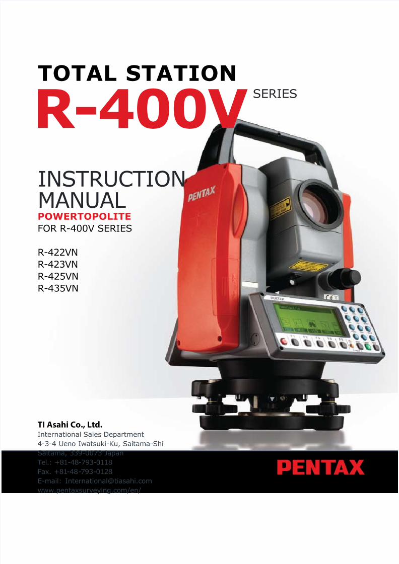
TOTAL STATION
INSTRUCTIONMANUALPOWERTOPOLITE
FOR R-400V SERIES
R-422VNR-423VNR-425VNR-435VN
TI Asahi Co., Ltd.International Sales Department4-3-4 Ueno Iwatsuki-Ku, Saitama-ShiSaitama, 339-0073 JapanTel.: +81-48-793-0118Fax. +81-48-793-0128E-mail: [email protected]/en/
R-400V SERIES
8/15/2019 r400v Man Ptl En
http://slidepdf.com/reader/full/r400v-man-ptl-en 2/142
1
CONTENTS
GENERALContents 1Exemption clause 4Copyright 4Display and Keyboard 5Operation Key 5Function Key 6Display combination of MODE A or MODE B 7Alphanumeric Input 7
1. INTRODUCTION 81.1 Introduction 81.2 Before using the PowerTopoLite manual 9
2. ACCESSING POWERTOPOLITE 112.1 How to access PowerTopoLite 112.2 Allocation of each PowerTopoLite Function key 122.3 Typical Function keys of PowerTopoLite 13
3. FILE MANAGER 143.1 Information of the remaining memory available 143.2 Creation of a new Job 143.3 Selection of a Job name 15
3.3.1 Selection of a Job 15
3.3.2 Selection by Job name input 153.4 Deletion of a Job name 16
3.4.1 Deletion from a Job list 163.4.2 Deletion from a Job name search 17
3.5 All Clear 17
4. MEASURE 184.1 Station setup [By Rectangular Coordinates] 19
4.1.1 Point Name input 194.1.2 Coordinates, X, Y, Z, IH, and PC input 204.1.3 Point selection from the list 21
4.2 Station Orientation 234.3 Multiple Orientation 244.4 Function of MEASURE screen 254.5 Remote, Offset, Station, and H. angle function 26
4.5.1 Remote 264.5.2 Offset 274.5.3 Station 294.5.4 H. angle 29
4.6 Station setup [By Polar Coordinates] 294.6.1 Point Name input 30
4.6.2 IH, TEMP, PRESS, ppm and PC input 304.7 Station Orientation 31
8/15/2019 r400v Man Ptl En
http://slidepdf.com/reader/full/r400v-man-ptl-en 3/142
2
4.8 Function of MEASURE screen 324.9 Offset 334.10 Station setup [By Rectangular & Polar Coordinates] 344.11 Station Orientation 354.12 Function of MEASURE screen 35
4.13 IH Measurement 38
5. VIEW AND EDIT 395.1 Graphical View 395.2 Create the Rectangular Point 405.3 Edit the Data 405.4 Point Code List 41
5.4.1 Point Code 415.4.2 Point Code Create 435.4.3 Point Code Edit 44
6. FREE STATIONING 456.1 Stationing by more than 3 known points 456.2 Stationing by two known points 48
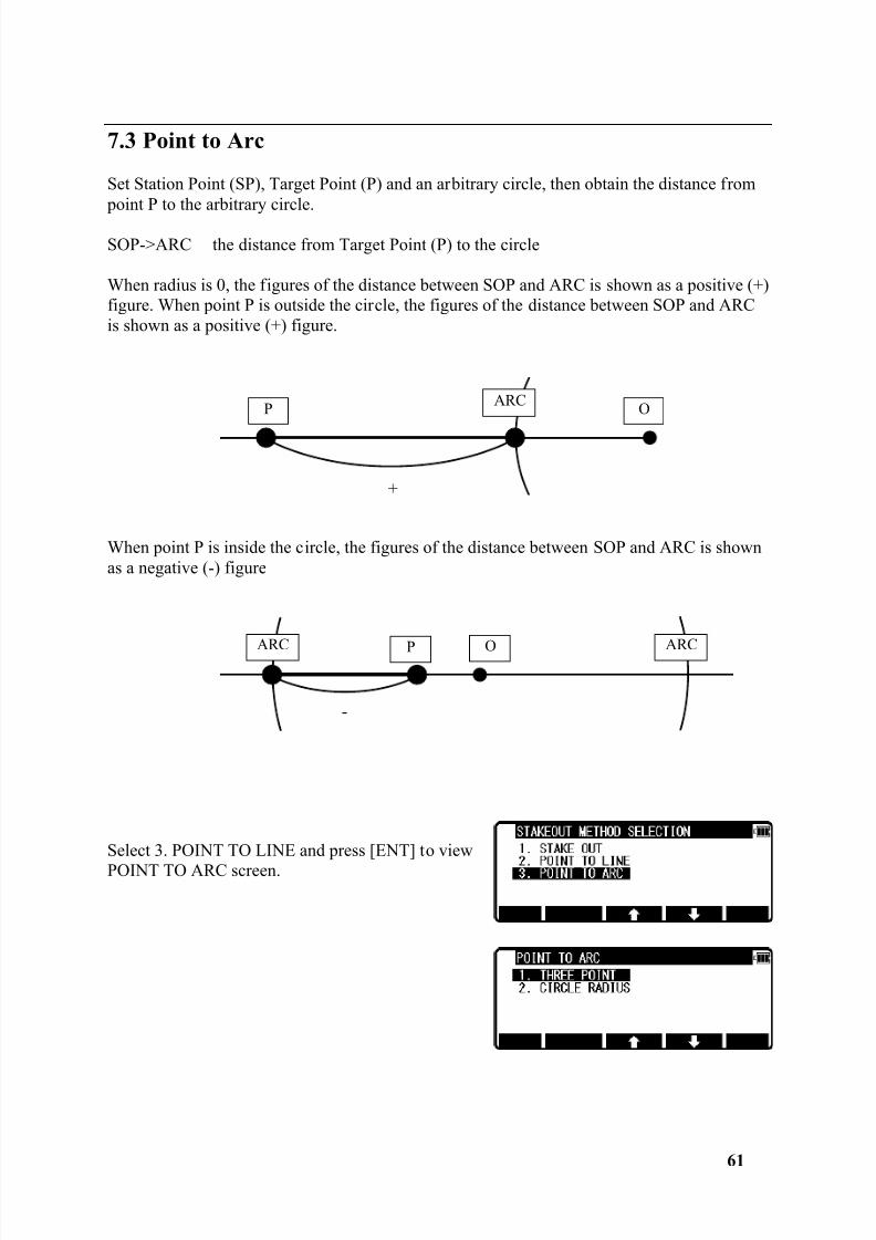
7. STAKE OUT 517.1 Stake Out 517.2 Point to Line 567.3 Point to Arc 58
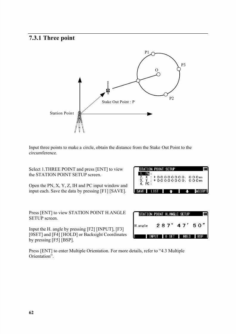
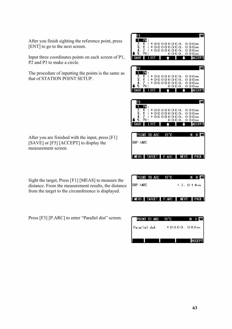
7.3.1 Three points 627.3.2 Circle radius 64
8. CALCULATIONS 668.1 Cogo 66
8.1.1 Inverse 678.1.2 Point Coordinates 70
8.1.2.1 Point Coordinates, Distance and H. angle 708.1.2.2 Distance and H. angle 728.1.2.3 H. angle input 73
8.1.3 Circle Radius 748.1.4 Line-Arc intersection 768.1.5 Line-line intersection 788.1.6 Arc-Arc intersection 808.1.7 Distance offset 828.1.8 Point distance offset 848.1.9 Arc distance offset 86
8.2 2D Surface 898.3 3D Surface and volume 928.4 REM 96
8.4.1 General pictures of measurement 96
9. VPM (Virtual Plane Measurement) 97
10. RDM (Remote Distance Measurement) 100
8/15/2019 r400v Man Ptl En
http://slidepdf.com/reader/full/r400v-man-ptl-en 4/142
3
10.1 PH input 10010.2 Reference point - Target distance 10010.3 Target- Target distance 10110.4 New Reference point selection 101
11. TRAVERSE 10211.1 Start point measuring 10411.2 Corner point measuring 10611.3 Calculation 108
12. INPUT / OUTPUT 11112.1 Text File read / write 113
12.1.1 Writing to Text File 11312.1.2 Reading from Text File 11412.1.3 Text file setup 117
12.1.3.1 Writing data setting 11712.1.3.2 Reading data setting 118
12.2 Communication with USB 11912.3 Communication with COM 120
12.3.1 Input from the PC 12012.3.2 Output to the PC 12112.3.3 Communication setup 122
12.3.3.1 Receiving data setting 12212.3.3.2 Sending data setting 123
12.3.4 About Data Link DL-01 Software 125
13. PREFERENCE 12913.1 Language selection 13013.2 Coordinate axis definition 13013.3 Input method selection 13213.4 Action method selection 13313.5 Remote method selection 13413.6 Compare method selection 13513.7 Request aiming selection 13613.8 EDM settings selection 13613.9 Elevation factor 13713.10 Duplicate point check 138
13.11 Meas. display 13913.12 Both faces Meas. 13913.13 Save Mode 140
8/15/2019 r400v Man Ptl En
http://slidepdf.com/reader/full/r400v-man-ptl-en 5/142
8/15/2019 r400v Man Ptl En
http://slidepdf.com/reader/full/r400v-man-ptl-en 6/142
5
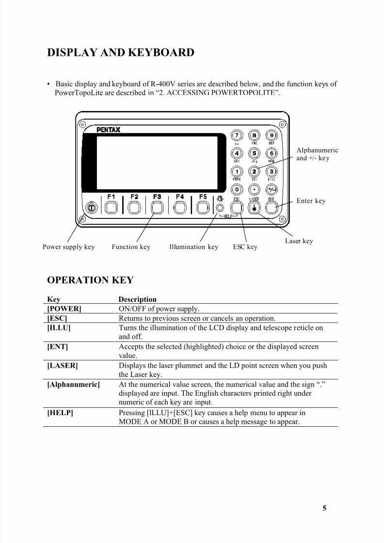
DISPLAY AND KEYBOARD
• Basic display and keyboard of R-400V series are described below, and the function keys of
PowerTopoLite are described in “2. ACCESSING POWERTOPOLITE”.
OPERATION KEYKey Description [POWER] ON/OFF of power supply.[ESC] Returns to previous screen or cancels an operation.[ILLU] Turns the illumination of the LCD display and telescope reticle on
and off.[ENT] Accepts the selected (highlighted) choice or the displayed screen
value.[LASER] Displays the laser plummet and the LD point screen when you push
the Laser key.[Alphanumeric] At the numerical value screen, the numerical value and the sign “.”
displayed are input. The English characters printed right undernumeric of each key are input.
[HELP] Pressing [lLLU]+[ESC] key causes a help menu to appear inMODE A or MODE B or causes a help message to appear.
Power supply key Function key Illumination key ESC keyLaser key
Enter key
Alphanumericand +/- key
8/15/2019 r400v Man Ptl En
http://slidepdf.com/reader/full/r400v-man-ptl-en 7/142
6
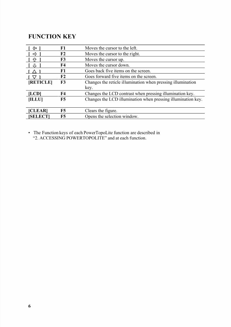
FUNCTION KEY
[ ] F1 Moves the cursor to the left.[ ] F2 Moves the cursor to the right.[ ] F3 Moves the cursor up.[ ] F4 Moves the cursor down.
F1 Goes back five items on the screen. F2 Goes forward five items on the screen.
[RETICLE] F3 Changes the reticle illumination when pressing illuminationkey.
[LCD] F4 Changes the LCD contrast when pressing illumination key.[ILLU] F5 Changes the LCD illumination when pressing illumination key.
[CLEAR] F5 Clears the figure.[SELECT] F5 Opens the selection window.
• The Function keys of each PowerTopoLite function are described in“2. ACCESSING POWERTOPOLITE” and at each function.

8/15/2019 r400v Man Ptl En
http://slidepdf.com/reader/full/r400v-man-ptl-en 8/142
7
Display combination of MODE A or MODE B
Function MODE A MODE B F1 MEAS S.FUNCF2 TARGET ANG SETF3 0 SET HOLDF4 DISP CORRF5 MODE MODE
• Mode A or Mode B is switched by pressing [F5] [MODE].
ALPHANUMERIC INPUT
The point name etc. is input by the alphanumeric keys as following.
Key Letter under key Letter & figure order to input
8/15/2019 r400v Man Ptl En
http://slidepdf.com/reader/full/r400v-man-ptl-en 9/142
8
1. INTRODUCTION1.1 Introduction
Thank you for your first look at PowerTopoLite by reading this manual.
The PowerTopoLite is a user friendly data collection and calculation program for thePENTAX R-400V Series Total Stations.PowerTopoLite is developed based on PowerTopo, which is known as a versatile on-boardsoftware for PENTAX ATS Series Total Stations. The optimum combination ofPowerTopoLite and R-400V hardware makes PowerTopoLite an easy and useful fieldworktool.The icon based main menu offers you the following possibilities.
• FILE MANAGER
• MEASURE
• VIEW AND EDIT
• FREE STATIONING
• STAKE OUT
• CALCULATIONS
• VIRTUAL PLANE MEASUREMENT
• REMOTE DISTANCE MEASUREMENT
• TRAVERSE
• TRANSFER
• PREFERENCE
8/15/2019 r400v Man Ptl En
http://slidepdf.com/reader/full/r400v-man-ptl-en 10/142
8/15/2019 r400v Man Ptl En
http://slidepdf.com/reader/full/r400v-man-ptl-en 11/142
8/15/2019 r400v Man Ptl En
http://slidepdf.com/reader/full/r400v-man-ptl-en 12/142
11
2. ACCESSING POWERTOPOLITE2.1 How to access PowerTopoLite
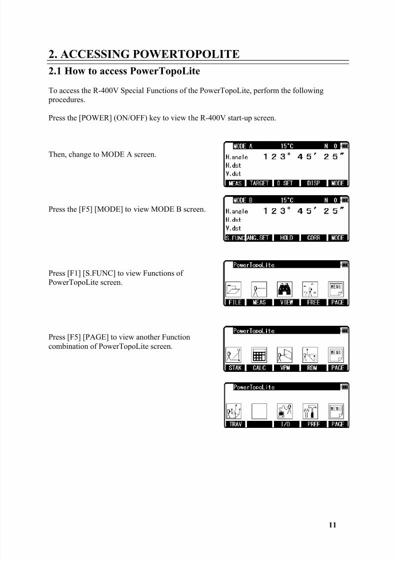
To access the R-400V Special Functions of the PowerTopoLite, perform the following procedures.
Press the [POWER] (ON/OFF) key to view the R-400V start-up screen.
Then, change to MODE A screen.
Press the [F5] [MODE] to view MODE B screen.
Press [F1] [S.FUNC] to view Functions ofPowerTopoLite screen.
Press [F5] [PAGE] to view another Functioncombination of PowerTopoLite screen.
8/15/2019 r400v Man Ptl En
http://slidepdf.com/reader/full/r400v-man-ptl-en 13/142
8/15/2019 r400v Man Ptl En
http://slidepdf.com/reader/full/r400v-man-ptl-en 14/142
13
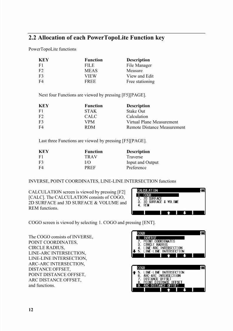
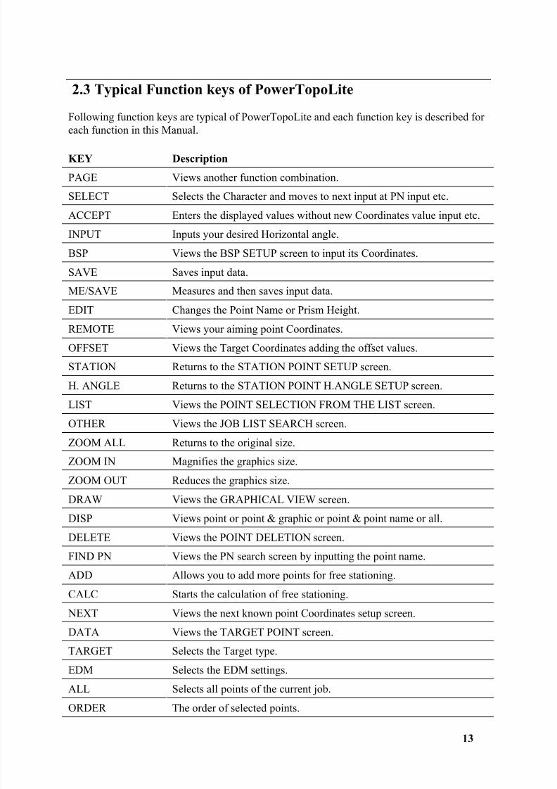
2.3 Typical Function keys of PowerTopoLite
Following function keys are typical of PowerTopoLite and each function key is described foreach function in this Manual.
KEY Description
PAGE Views another function combination.
SELECT Selects the Character and moves to next input at PN input etc.
ACCEPT Enters the displayed values without new Coordinates value input etc.
INPUT Inputs your desired Horizontal angle.
BSP Views the BSP SETUP screen to input its Coordinates.
SAVE Saves input data.ME/SAVE Measures and then saves input data.
EDIT Changes the Point Name or Prism Height.
REMOTE Views your aiming point Coordinates.
OFFSET Views the Target Coordinates adding the offset values.
STATION Returns to the STATION POINT SETUP screen.
H. ANGLE Returns to the STATION POINT H.ANGLE SETUP screen.
LIST Views the POINT SELECTION FROM THE LIST screen.
OTHER Views the JOB LIST SEARCH screen.
ZOOM ALL Returns to the original size.
ZOOM IN Magnifies the graphics size.
ZOOM OUT Reduces the graphics size.
DRAW Views the GRAPHICAL VIEW screen.
DISP Views point or point & graphic or point & point name or all.
DELETE Views the POINT DELETION screen.
FIND PN Views the PN search screen by inputting the point name.
ADD Allows you to add more points for free stationing.
CALC Starts the calculation of free stationing.
NEXT Views the next known point Coordinates setup screen.
DATA Views the TARGET POINT screen.
TARGET Selects the Target type.
EDM Selects the EDM settings.
ALL Selects all points of the current job.ORDER The order of selected points.
8/15/2019 r400v Man Ptl En
http://slidepdf.com/reader/full/r400v-man-ptl-en 15/142
14
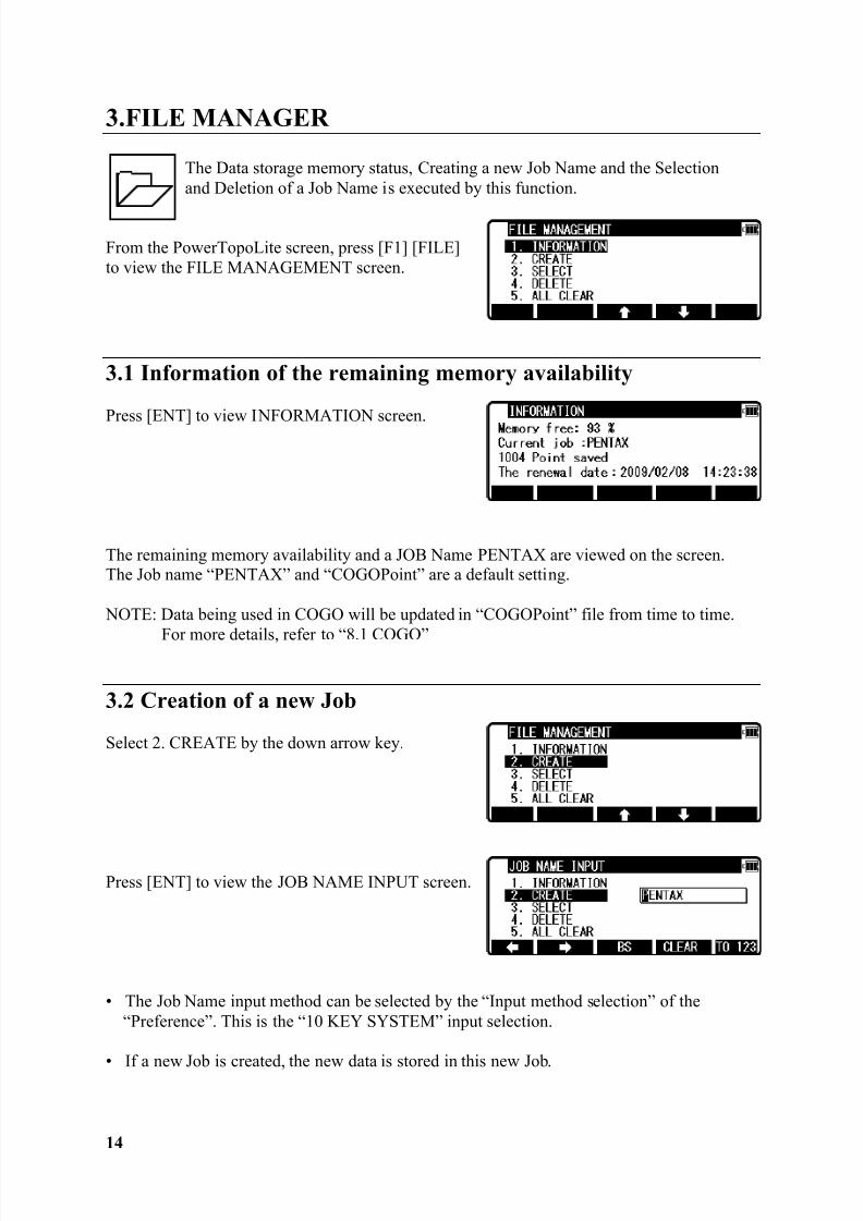
3.FILE MANAGER
The Data storage memory status, Creating a new Job Name and the Selectionand Deletion of a Job Name is executed by this function.
From the PowerTopoLite screen, press [F1] [FILE]to view the FILE MANAGEMENT screen.
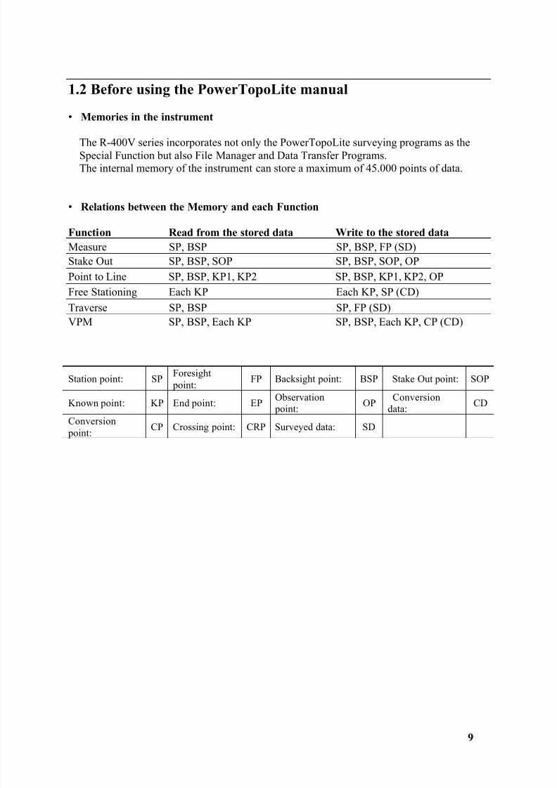
3.1 Information of the remaining memory availability
Press [ENT] to view INFORMATION screen.
The remaining memory availability and a JOB Name PENTAX are viewed on the screen.The Job name “PENTAX” and “COGOPoint” are a default setting.
NOTE: Data being used in COGO will be updated in “COGOPoint” file from time to time.
For more details, refer to “8.1 COGO”
3.2 Creation of a new Job
Select 2. CREATE by the down arrow key.
Press [ENT] to view the JOB NAME INPUT screen.
• The Job Name input method can be selected by the “Input method selection” of the“Preference”. This is the “10 KEY SYSTEM” input selection.
• If a new Job is created, the new data is stored in this new Job.
8/15/2019 r400v Man Ptl En
http://slidepdf.com/reader/full/r400v-man-ptl-en 16/142
15
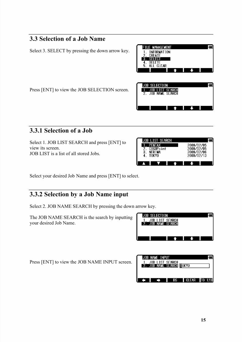
3.3 Selection of a Job Name
Select 3. SELECT by pressing the down arrow key.
Press [ENT] to view the JOB SELECTION screen.
3.3.1 Selection of a Job
Select 1. JOB LIST SEARCH and press [ENT] toview its screen.JOB LIST is a list of all stored Jobs.
Select your desired Job Name and press [ENT] to select.
3.3.2 Selection by a Job Name input
Select 2. JOB NAME SEARCH by pressing the down arrow key.
The JOB NAME SEARCH is the search by inputtingyour desired Job Name.
Press [ENT] to view the JOB NAME INPUT screen.

8/15/2019 r400v Man Ptl En
http://slidepdf.com/reader/full/r400v-man-ptl-en 17/142
16
Input your desired JOB NAME and press [ENT] toview the JOB LIST SEARCH screen.
Press [ENT] to select this.
3.4 Deletion of a Job Name
Select 4. DELETE by pressing the down arrow key.
Press [ENT] to view the JOB DELETION screen.
3.4.1 Deletion from a Job List
Select 1. JOB LIST SEARCH and Press [ENT] toview its screen.
If TOKYO is selected, deletion confirmation screenis viewed.
Press [ENT] to delete or [ESC] to abort.
8/15/2019 r400v Man Ptl En
http://slidepdf.com/reader/full/r400v-man-ptl-en 18/142
17
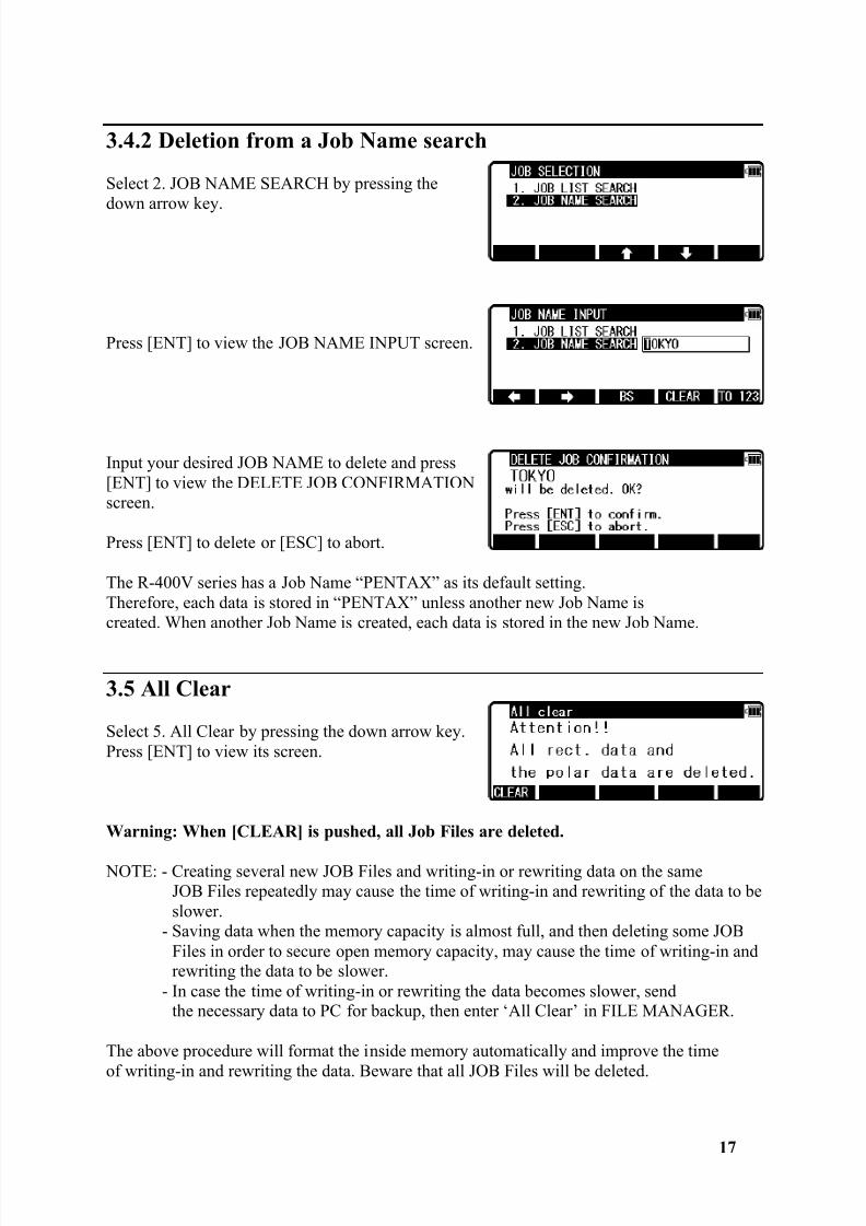
3.4.2 Deletion from a Job Name search
Select 2. JOB NAME SEARCH by pressing thedown arrow key.
Press [ENT] to view the JOB NAME INPUT screen.
Input your desired JOB NAME to delete and press[ENT] to view the DELETE JOB CONFIRMATIONscreen.
Press [ENT] to delete or [ESC] to abort.
The R-400V series has a Job Name “PENTAX” as its default setting.Therefore, each data is stored in “PENTAX” unless another new Job Name iscreated. When another Job Name is created, each data is stored in the new Job Name.
3.5 All Clear
Select 5. All Clear by pressing the down arrow key.Press [ENT] to view its screen.
Warning: When [CLEAR] is pushed, all Job Files are deleted.
NOTE: - Creating several new JOB Files and writing-in or rewriting data on the sameJOB Files repeatedly may cause the time of writing-in and rewriting of the data to beslower.
- Saving data when the memory capacity is almost full, and then deleting some JOBFiles in order to secure open memory capacity, may cause the time of writing-in andrewriting the data to be slower.
- In case the time of writing-in or rewriting the data becomes slower, sendthe necessary data to PC for backup, then enter ‘All Clear’ in FILE MANAGER.
The above procedure will format the inside memory automatically and improve the time
of writing-in and rewriting the data. Beware that all JOB Files will be deleted.
8/15/2019 r400v Man Ptl En
http://slidepdf.com/reader/full/r400v-man-ptl-en 19/142
18
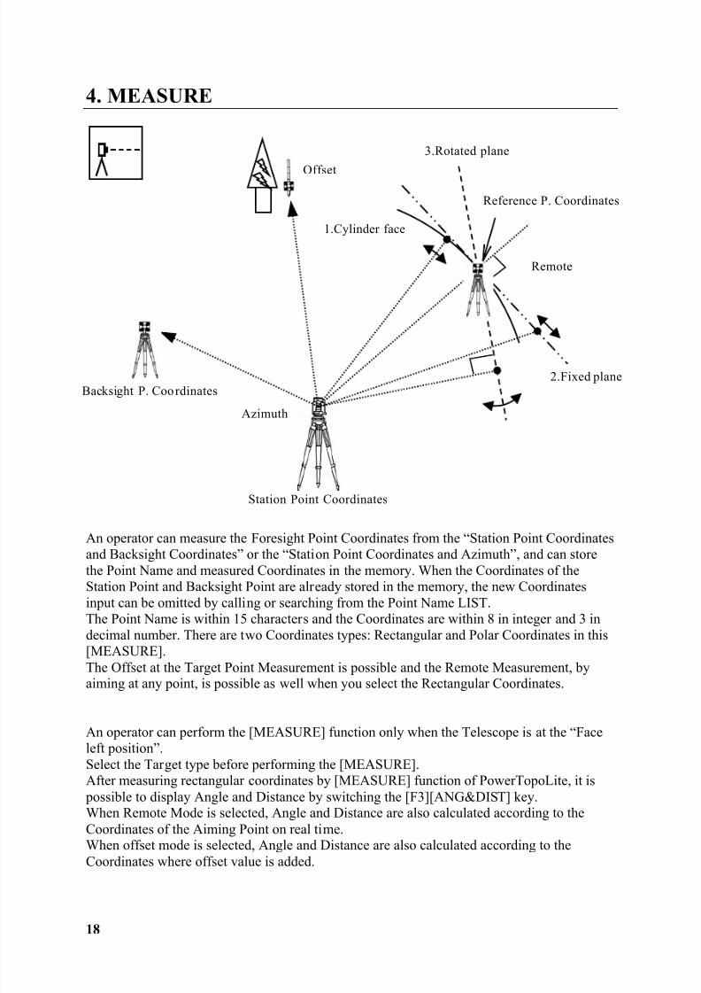
4. MEASURE
An operator can measure the Foresight Point Coordinates from the “Station Point Coordinatesand Backsight Coordinates” or the “Station Point Coordinates and Azimuth”, and can storethe Point Name and measured Coordinates in the memory. When the Coordinates of theStation Point and Backsight Point are already stored in the memory, the new Coordinatesinput can be omitted by calling or searching from the Point Name LIST.The Point Name is within 15 characters and the Coordinates are within 8 in integer and 3 indecimal number. There are two Coordinates types: Rectangular and Polar Coordinates in this[MEASURE].The Offset at the Target Point Measurement is possible and the Remote Measurement, byaiming at any point, is possible as well when you select the Rectangular Coordinates.
An operator can perform the [MEASURE] function only when the Telescope is at the “Faceleft position”.Select the Target type before performing the [MEASURE].After measuring rectangular coordinates by [MEASURE] function of PowerTopoLite, it is possible to display Angle and Distance by switching the [F3][ANG&DIST] key.When Remote Mode is selected, Angle and Distance are also calculated according to theCoordinates of the Aiming Point on real time.When offset mode is selected, Angle and Distance are also calculated according to theCoordinates where offset value is added.
Backsight P. Coo rdinates
Azimuth
Reference P. Coordinates
1.Cylinder face
2.Fixed plane
3.Rotated plane
Station Point Coordinates
Offset
Remote
8/15/2019 r400v Man Ptl En
http://slidepdf.com/reader/full/r400v-man-ptl-en 20/142
19
4.1 Station setup [By Rectangular Coordinates]
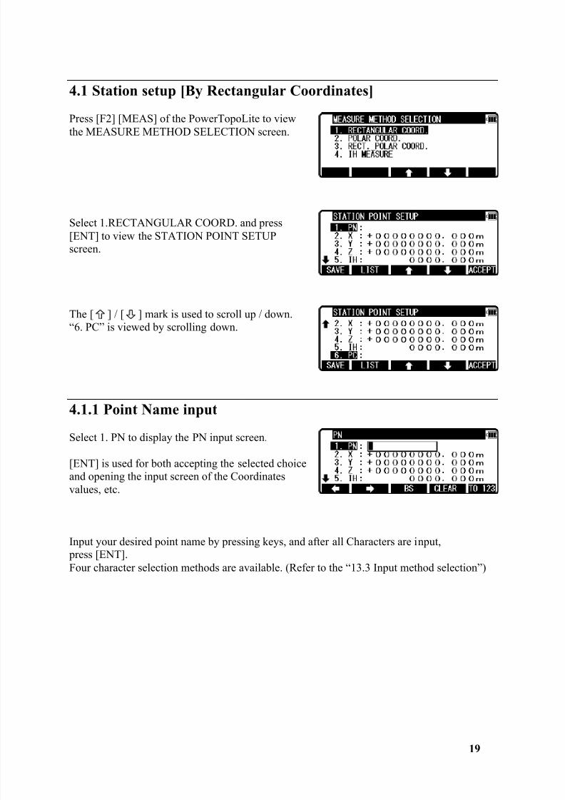
Press [F2] [MEAS] of the PowerTopoLite to viewthe MEASURE METHOD SELECTION screen.
Select 1.RECTANGULAR COORD. and press[ENT] to view the STATION POINT SETUPscreen.
The [ ] / [ ] mark is used to scroll up / down.“6. PC” is viewed by scrolling down.
4.1.1 Point Name input
Select 1. PN to display the PN input screen.
[ENT] is used for both accepting the selected choiceand opening the input screen of the Coordinatesvalues, etc.
Input your desired point name by pressing keys, and after all Characters are input, press [ENT].Four character selection methods are available. (Refer to the “13.3 Input method selection”)
8/15/2019 r400v Man Ptl En
http://slidepdf.com/reader/full/r400v-man-ptl-en 21/142
20
4.1.2 Coordinates, X, Y, Z, IH, and PC input
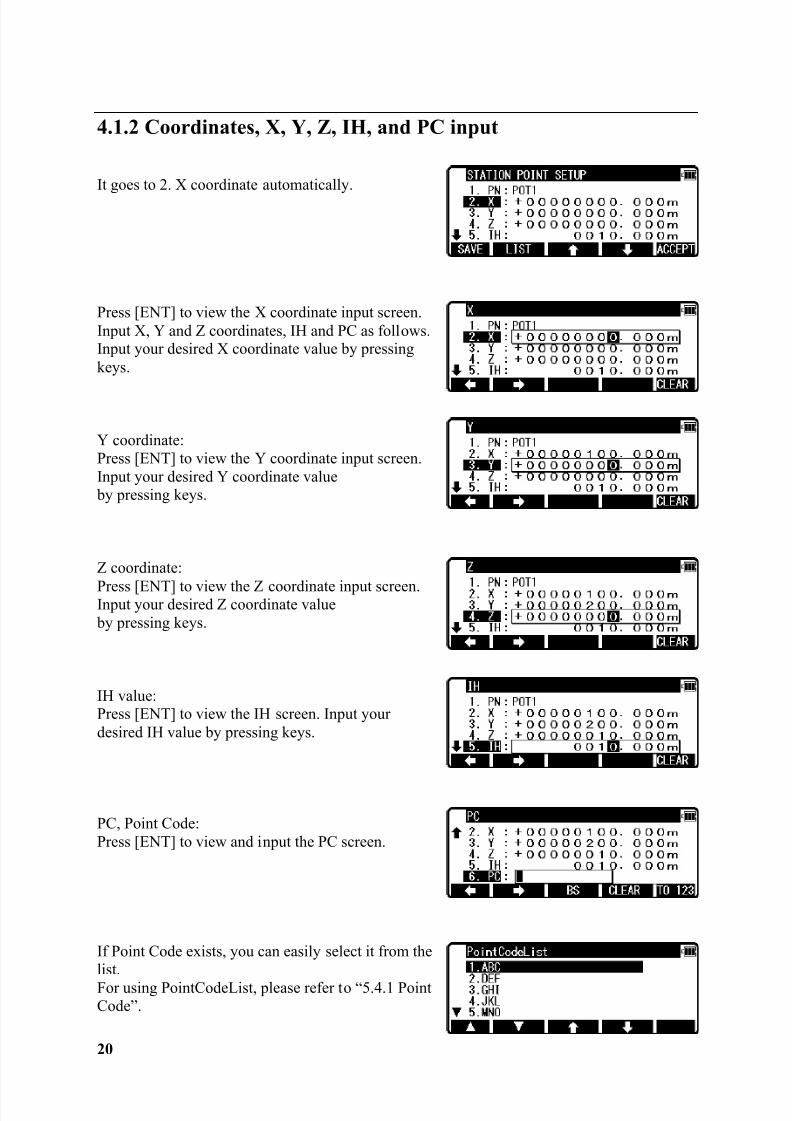
It goes to 2. X coordinate automatically.
Press [ENT] to view the X coordinate input screen.Input X, Y and Z coordinates, IH and PC as follows.Input your desired X coordinate value by pressingkeys.
Y coordinate:Press [ENT] to view the Y coordinate input screen.Input your desired Y coordinate value by pressing keys.
Z coordinate:
Press [ENT] to view the Z coordinate input screen.Input your desired Z coordinate value by pressing keys.
IH value:Press [ENT] to view the IH screen. Input yourdesired IH value by pressing keys.
PC, Point Code:Press [ENT] to view and input the PC screen.
If Point Code exists, you can easily select it from thelist.For using PointCodeList, please refer to “5.4.1 PointCode”.
8/15/2019 r400v Man Ptl En
http://slidepdf.com/reader/full/r400v-man-ptl-en 22/142
21
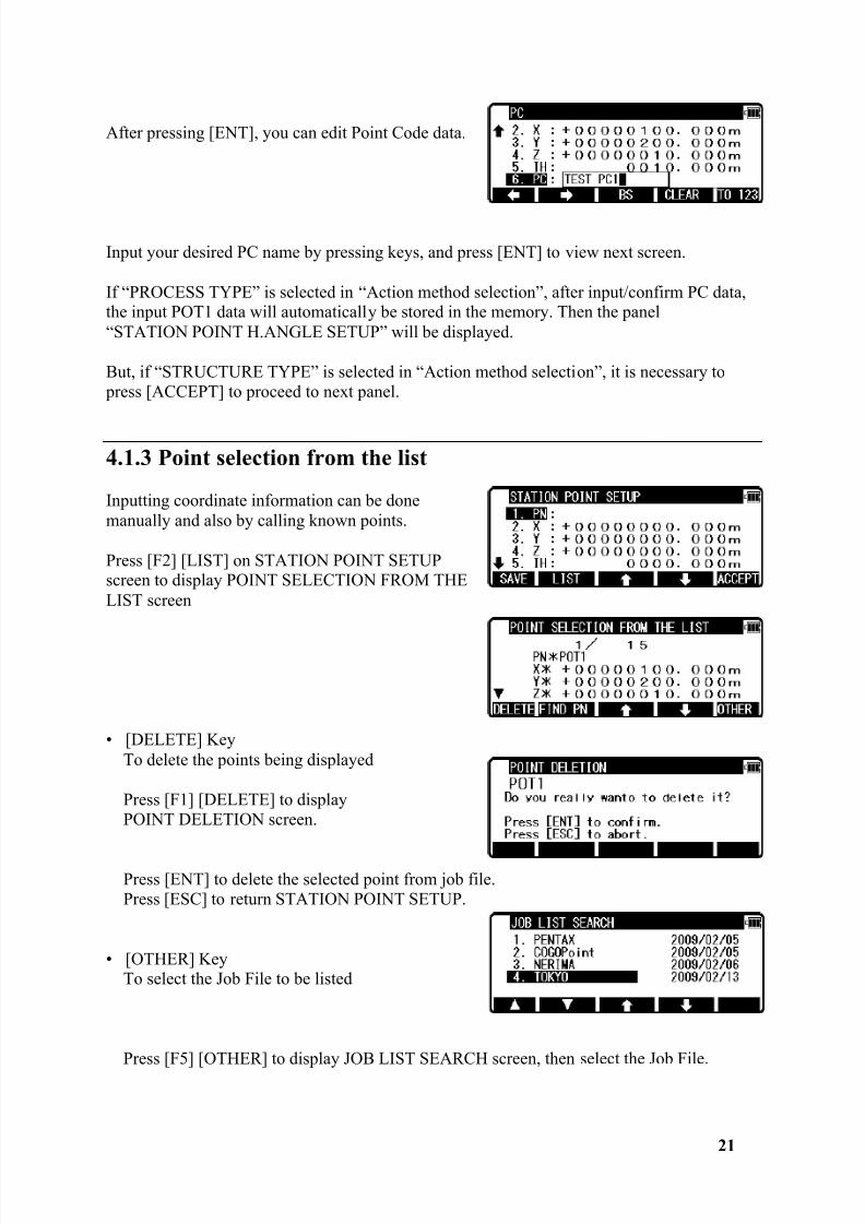
After pressing [ENT], you can edit Point Code data.
Input your desired PC name by pressing keys, and press [ENT] to view next screen.
If “PROCESS TYPE” is selected in “Action method selection”, after input/confirm PC data,the input POT1 data will automatically be stored in the memory. Then the panel“STATION POINT H.ANGLE SETUP” will be displayed.
But, if “STRUCTURE TYPE” is selected in “Action method selection”, it is necessary to press [ACCEPT] to proceed to next panel.
4.1.3 Point selection from the list
Inputting coordinate information can be donemanually and also by calling known points.
Press [F2] [LIST] on STATION POINT SETUPscreen to display POINT SELECTION FROM THELIST screen
• [DELETE] KeyTo delete the points being displayed
Press [F1] [DELETE] to displayPOINT DELETION screen.
Press [ENT] to delete the selected point from job file.Press [ESC] to return STATION POINT SETUP.
• [OTHER] KeyTo select the Job File to be listed
Press [F5] [OTHER] to display JOB LIST SEARCH screen, then select the Job File.
8/15/2019 r400v Man Ptl En
http://slidepdf.com/reader/full/r400v-man-ptl-en 23/142
22
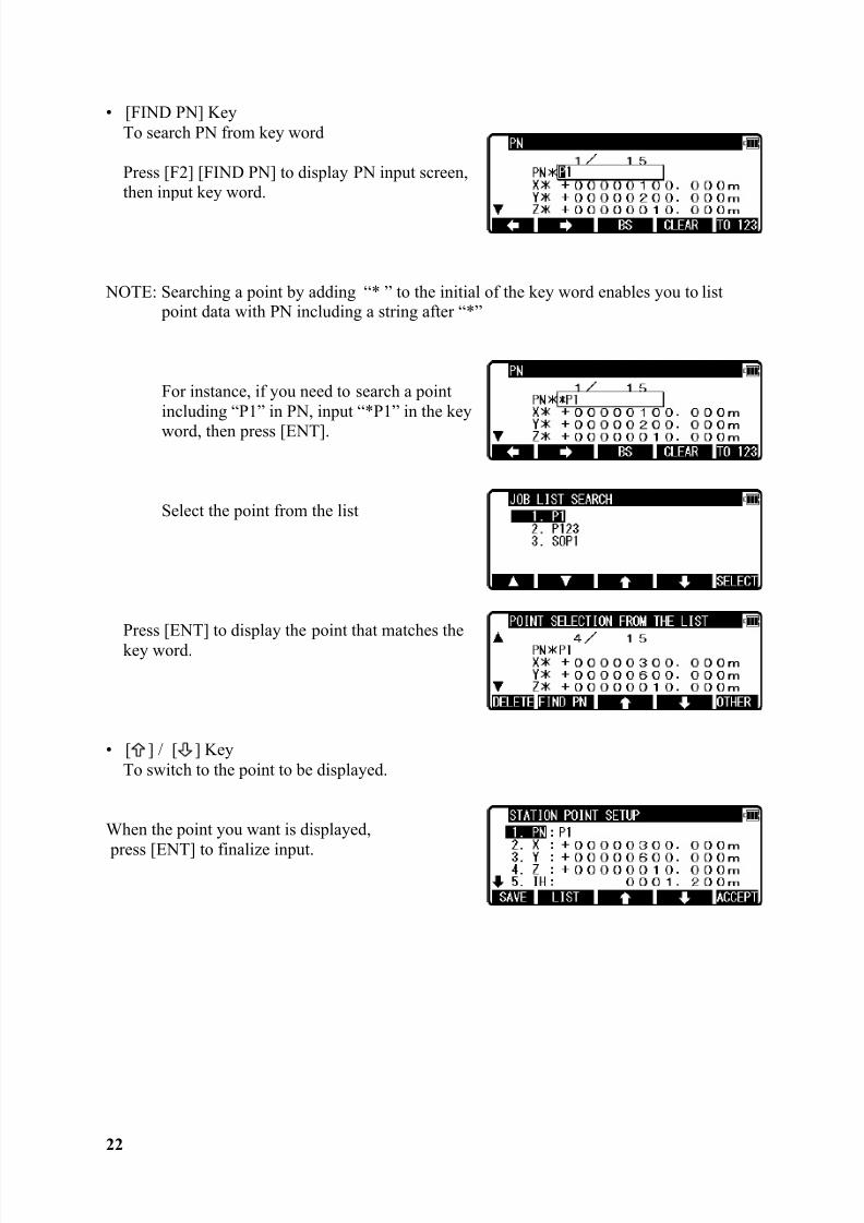
• [FIND PN] KeyTo search PN from key word
Press [F2] [FIND PN] to display PN input screen,then input key word.
NOTE: Searching a point by adding “* ” to the initial of the key word enables you to list point data with PN including a string after “*”
For instance, if you need to search a pointincluding “P1” in PN, input “*P1” in the keyword, then press [ENT].
Select the point from the list
Press [ENT] to display the point that matches thekey word.
• [ ] / [ ] KeyTo switch to the point to be displayed.
When the point you want is displayed,
press [ENT] to finalize input.
8/15/2019 r400v Man Ptl En
http://slidepdf.com/reader/full/r400v-man-ptl-en 24/142
23
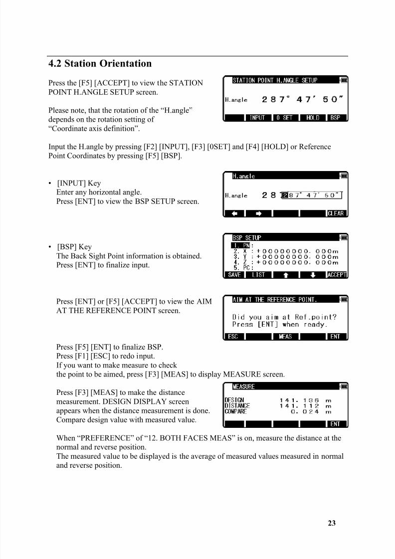
4.2 Station Orientation
Press the [F5] [ACCEPT] to view the STATIONPOINT H.ANGLE SETUP screen.
Please note, that the rotation of the “H.angle”depends on the rotation setting of“Coordinate axis definition”.
Input the H.angle by pressing [F2] [INPUT], [F3] [0SET] and [F4] [HOLD] or ReferencePoint Coordinates by pressing [F5] [BSP].
• [INPUT] Key
Enter any horizontal angle.Press [ENT] to view the BSP SETUP screen.
• [BSP] KeyThe Back Sight Point information is obtained.Press [ENT] to finalize input.
Press [ENT] or [F5] [ACCEPT] to view the AIMAT THE REFERENCE POINT screen.
Press [F5] [ENT] to finalize BSP.Press [F1] [ESC] to redo input.If you want to make measure to checkthe point to be aimed, press [F3] [MEAS] to display MEASURE screen.
Press [F3] [MEAS] to make the distancemeasurement. DESIGN DISPLAY screenappears when the distance measurement is done.Compare design value with measured value.
When “PREFERENCE” of “12. BOTH FACES MEAS” is on, measure the distance at thenormal and reverse position.The measured value to be displayed is the average of measured values measured in normaland reverse position.
8/15/2019 r400v Man Ptl En
http://slidepdf.com/reader/full/r400v-man-ptl-en 25/142
24
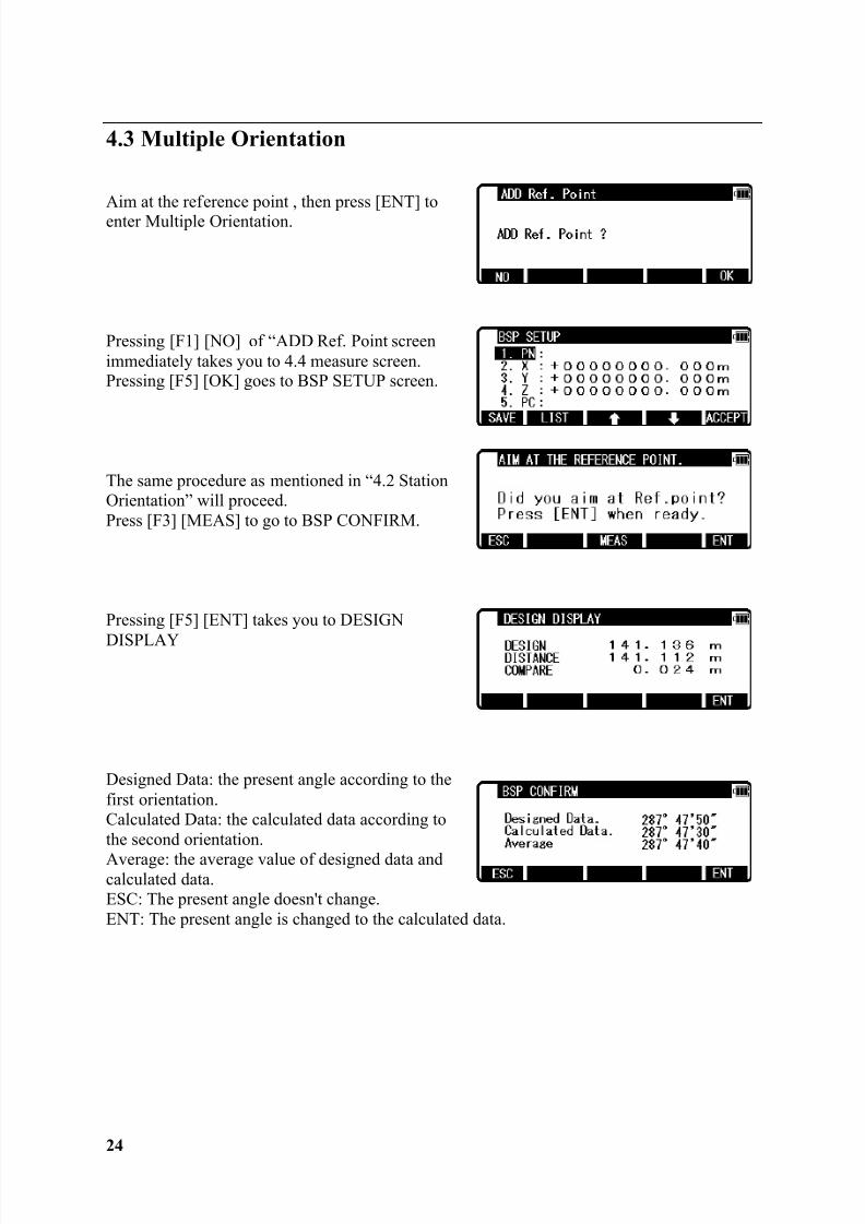
4.3 Multiple Orientation
Aim at the reference point , then press [ENT] toenter Multiple Orientation.
Pressing [F1] [NO] of “ADD Ref. Point screenimmediately takes you to 4.4 measure screen.Pressing [F5] [OK] goes to BSP SETUP screen.
The same procedure as mentioned in “4.2 StationOrientation” will proceed.Press [F3] [MEAS] to go to BSP CONFIRM.
Pressing [F5] [ENT] takes you to DESIGN
DISPLAY
Designed Data: the present angle according to thefirst orientation.Calculated Data: the calculated data according tothe second orientation.Average: the average value of designed data andcalculated data.ESC: The present angle doesn't change.ENT: The present angle is changed to the calculated data.
8/15/2019 r400v Man Ptl En
http://slidepdf.com/reader/full/r400v-man-ptl-en 26/142
8/15/2019 r400v Man Ptl En
http://slidepdf.com/reader/full/r400v-man-ptl-en 27/142
8/15/2019 r400v Man Ptl En
http://slidepdf.com/reader/full/r400v-man-ptl-en 28/142
27
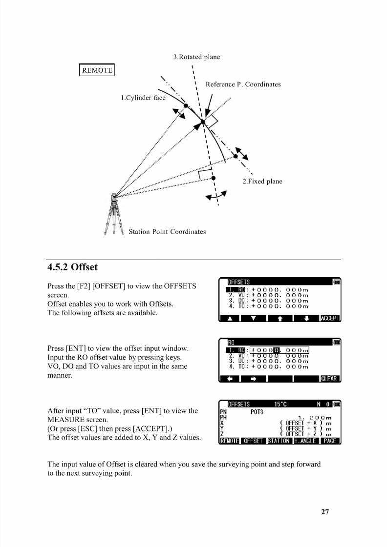
4.5.2 Offset
Press the [F2] [OFFSET] to view the OFFSETSscreen.Offset enables you to work with Offsets.The following offsets are available.
Press [ENT] to view the offset input window.Input the RO offset value by pressing keys.VO, DO and TO values are input in the samemanner.
After input “TO” value, press [ENT] to view theMEASURE screen.(Or press [ESC] then press [ACCEPT].)The offset values are added to X, Y and Z values.
The input value of Offset is cleared when you save the surveying point and step forwardto the next surveying point.
1.Cylinder face
Reference P . Coordinates
2.Fixed plane
3.Rotated plane
Station Point Coordinates
REMOTE
8/15/2019 r400v Man Ptl En
http://slidepdf.com/reader/full/r400v-man-ptl-en 29/142
28
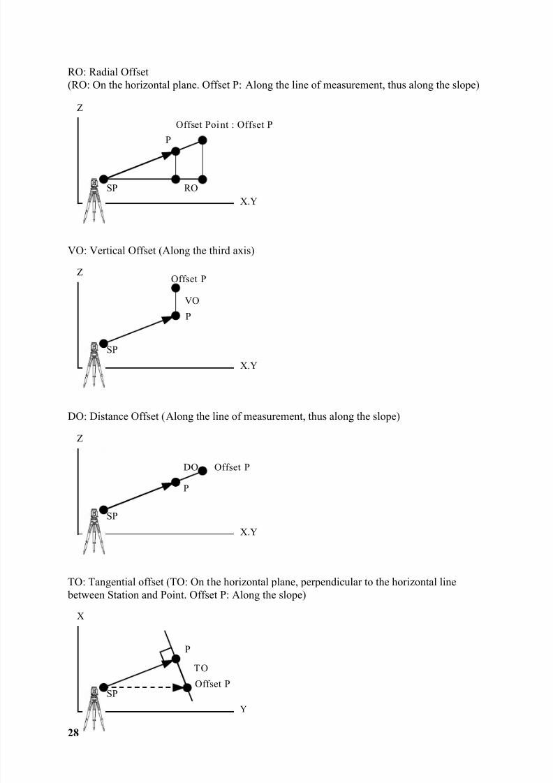
RO: Radial Offset(RO: On the horizontal plane. Offset P: Along the line of measurement, thus along the slope)
VO: Vertical Offset (Along the third axis)
DO: Distance Offset (Along the line of measurement, thus along the slope)
TO: Tangential offset (TO: On the horizontal plane, perpendicular to the horizontal line between Station and Point. Offset P: Along the slope)
Z
SP RO
Offset Point : Offset P
X.Y
P
Z
SP
VO
Offset P
X.Y
P
Z
SP
DO Offset P
X.Y
P
X
SP
TO
Offset P
Y
P
8/15/2019 r400v Man Ptl En
http://slidepdf.com/reader/full/r400v-man-ptl-en 30/142
29
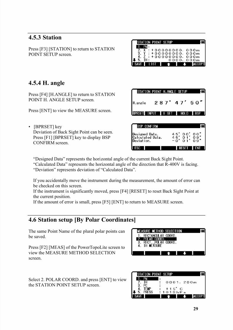
4.5.3 Station
Press [F3] [STATION] to return to STATIONPOINT SETUP screen.
4.5.4 H. angle
Press [F4] [H.ANGLE] to return to STATIONPOINT H. ANGLE SETUP screen.
Press [ENT] to view the MEASURE screen.
• [BPRSET] keyDeviation of Back Sight Point can be seen.Press [F1] [BPRSET] key to display BSPCONFIRM screen.
“Designed Data” represents the horizontal angle of the current Back Sight Point.“Calculated Data” represents the horizontal angle of the direction that R-400V is facing.“Deviation” represents deviation of “Calculated Data”.
If you accidentally move the instrument during the measurement, the amount of error can be checked on this screen.If the instrument is significantly moved, press [F4] [RESET] to reset Back Sight Point atthe current position.If the amount of error is small, press [F5] [ENT] to return to MEASURE screen.
4.6 Station setup [By Polar Coordinates]
The same Point Name of the plural polar points can be saved.
Press [F2] [MEAS] of the PowerTopoLite screen toview the MEASURE METHOD SELECTIONscreen.
Select 2. POLAR COORD. and press [ENT] to viewthe STATION POINT SETUP screen.
8/15/2019 r400v Man Ptl En
http://slidepdf.com/reader/full/r400v-man-ptl-en 31/142
30
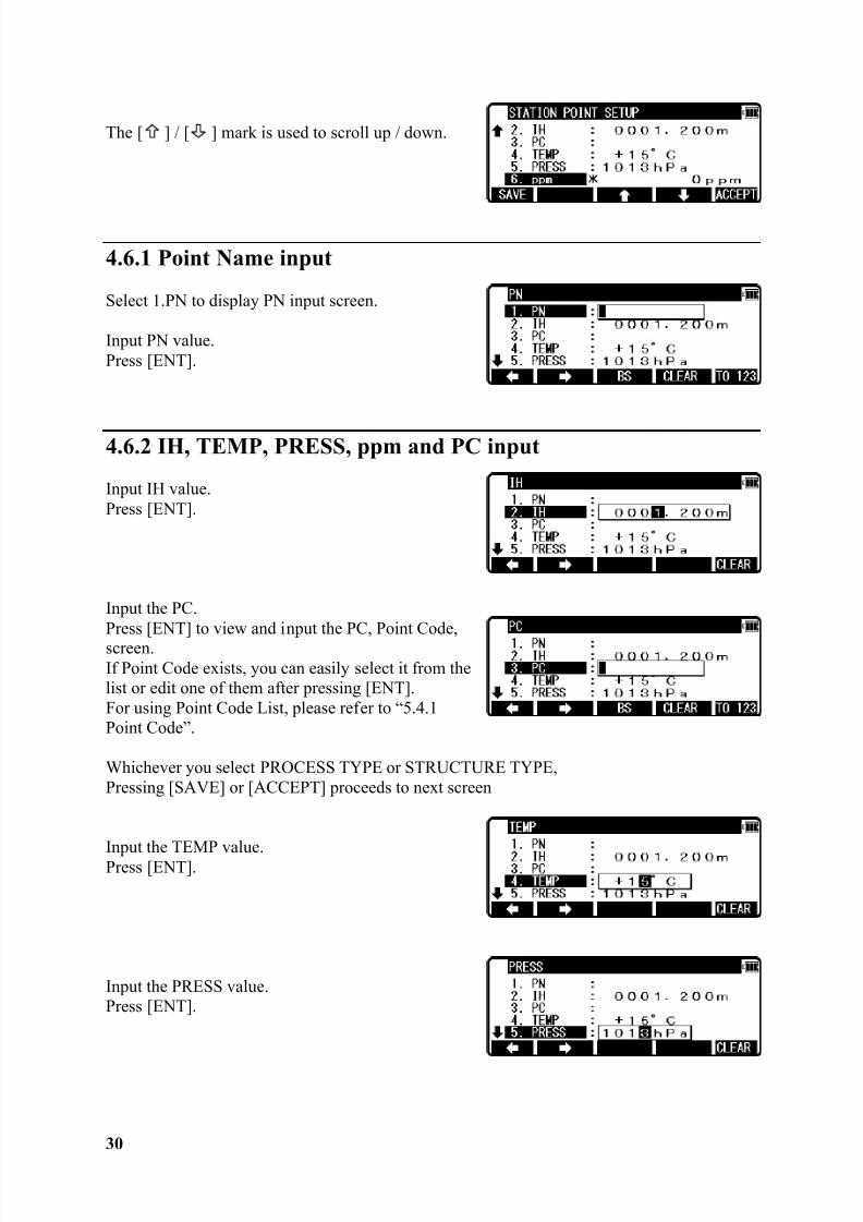
The [ ] / [ ] mark is used to scroll up / down.
4.6.1 Point Name input
Select 1.PN to display PN input screen.
Input PN value.Press [ENT].
4.6.2 IH, TEMP, PRESS, ppm and PC input
Input IH value.Press [ENT].
Input the PC.Press [ENT] to view and input the PC, Point Code,screen.If Point Code exists, you can easily select it from thelist or edit one of them after pressing [ENT].For using Point Code List, please refer to “5.4.1Point Code”.
Whichever you select PROCESS TYPE or STRUCTURE TYPE,Pressing [SAVE] or [ACCEPT] proceeds to next screen
Input the TEMP value.Press [ENT].
Input the PRESS value.Press [ENT].
8/15/2019 r400v Man Ptl En
http://slidepdf.com/reader/full/r400v-man-ptl-en 32/142
31
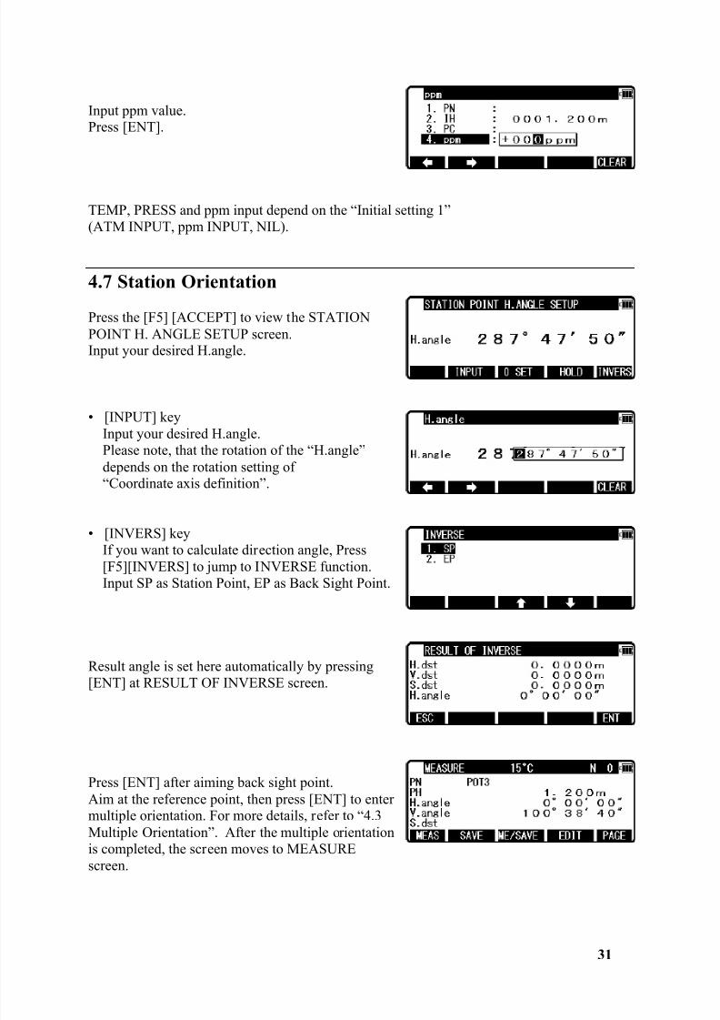
Input ppm value.Press [ENT].
TEMP, PRESS and ppm input depend on the “Initial setting 1”(ATM INPUT, ppm INPUT, NIL).
4.7 Station Orientation
Press the [F5] [ACCEPT] to view the STATIONPOINT H. ANGLE SETUP screen.
Input your desired H.angle.
• [INPUT] keyInput your desired H.angle.Please note, that the rotation of the “H.angle”depends on the rotation setting of“Coordinate axis definition”.
• [INVERS] keyIf you want to calculate direction angle, Press[F5][INVERS] to jump to INVERSE function.Input SP as Station Point, EP as Back Sight Point.
Result angle is set here automatically by pressing[ENT] at RESULT OF INVERSE screen.
Press [ENT] after aiming back sight point.Aim at the reference point, then press [ENT] to entermultiple orientation. For more details, refer to “4.3Multiple Orientation”. After the multiple orientationis completed, the screen moves to MEASUREscreen.
8/15/2019 r400v Man Ptl En
http://slidepdf.com/reader/full/r400v-man-ptl-en 33/142
32
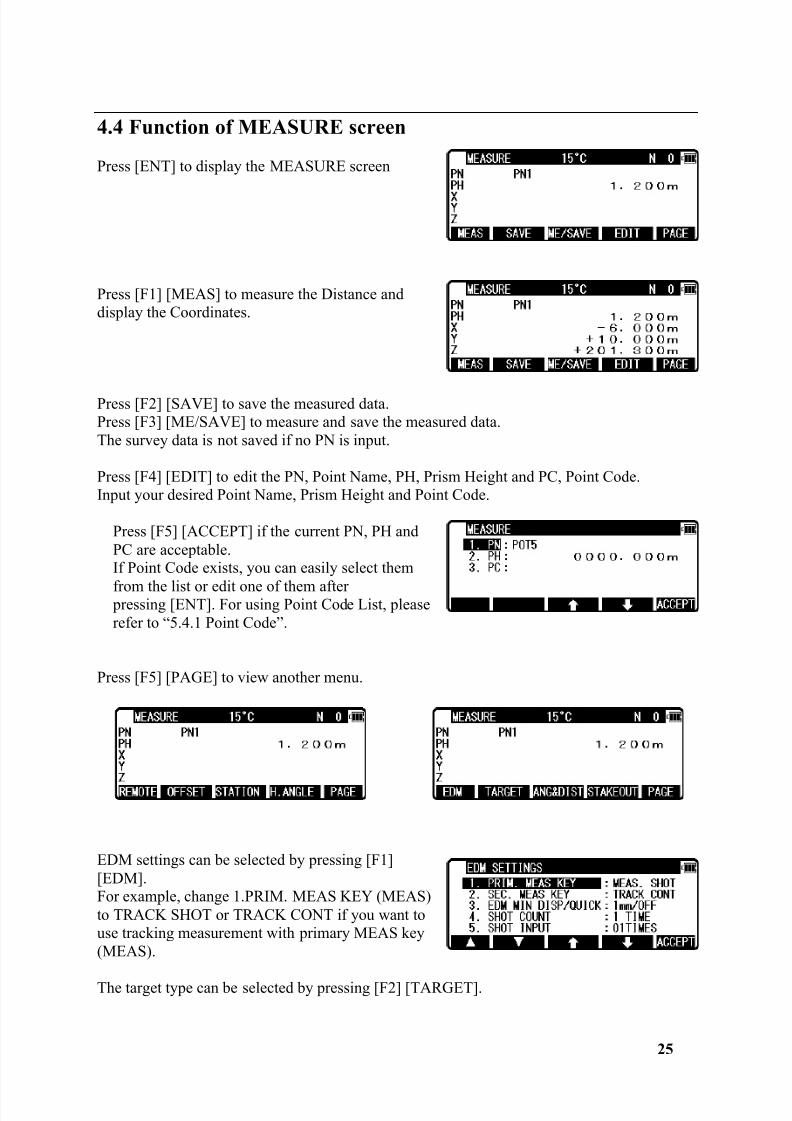
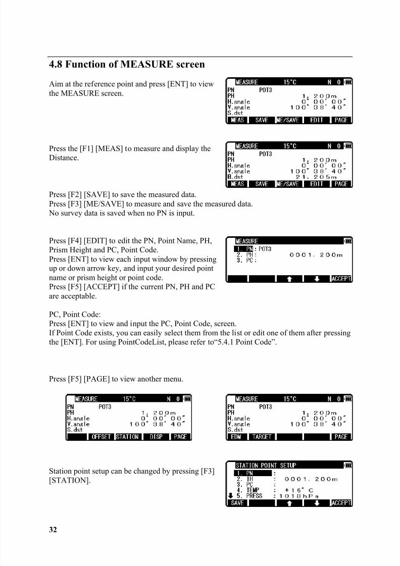
4.8 Function of MEASURE screen
Aim at the reference point and press [ENT] to viewthe MEASURE screen.
Press the [F1] [MEAS] to measure and display theDistance.
Press [F2] [SAVE] to save the measured data.Press [F3] [ME/SAVE] to measure and save the measured data. No survey data is saved when no PN is input.
Press [F4] [EDIT] to edit the PN, Point Name, PH,Prism Height and PC, Point Code.Press [ENT] to view each input window by pressingup or down arrow key, and input your desired pointname or prism height or point code.Press [F5] [ACCEPT] if the current PN, PH and PC
are acceptable.
PC, Point Code:Press [ENT] to view and input the PC, Point Code, screen.If Point Code exists, you can easily select them from the list or edit one of them after pressingthe [ENT]. For using PointCodeList, please refer to“5.4.1 Point Code”.
Press [F5] [PAGE] to view another menu.
Station point setup can be changed by pressing [F3][STATION].
8/15/2019 r400v Man Ptl En
http://slidepdf.com/reader/full/r400v-man-ptl-en 34/142
33
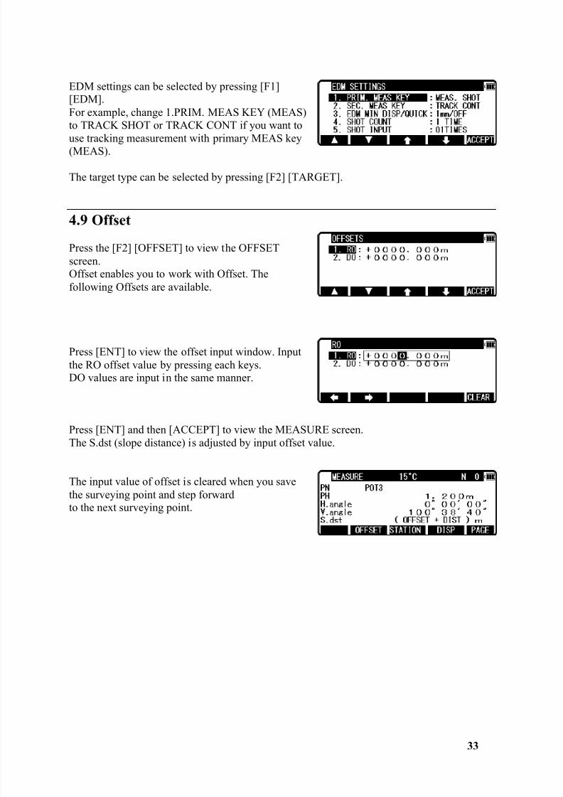
EDM settings can be selected by pressing [F1][EDM].For example, change 1.PRIM. MEAS KEY (MEAS)to TRACK SHOT or TRACK CONT if you want to
use tracking measurement with primary MEAS key(MEAS).
The target type can be selected by pressing [F2] [TARGET].
4.9 Offset
Press the [F2] [OFFSET] to view the OFFSETscreen.
Offset enables you to work with Offset. Thefollowing Offsets are available.
Press [ENT] to view the offset input window. Inputthe RO offset value by pressing each keys.DO values are input in the same manner.
Press [ENT] and then [ACCEPT] to view the MEASURE screen.The S.dst (slope distance) is adjusted by input offset value.
The input value of offset is cleared when you savethe surveying point and step forwardto the next surveying point.
8/15/2019 r400v Man Ptl En
http://slidepdf.com/reader/full/r400v-man-ptl-en 35/142
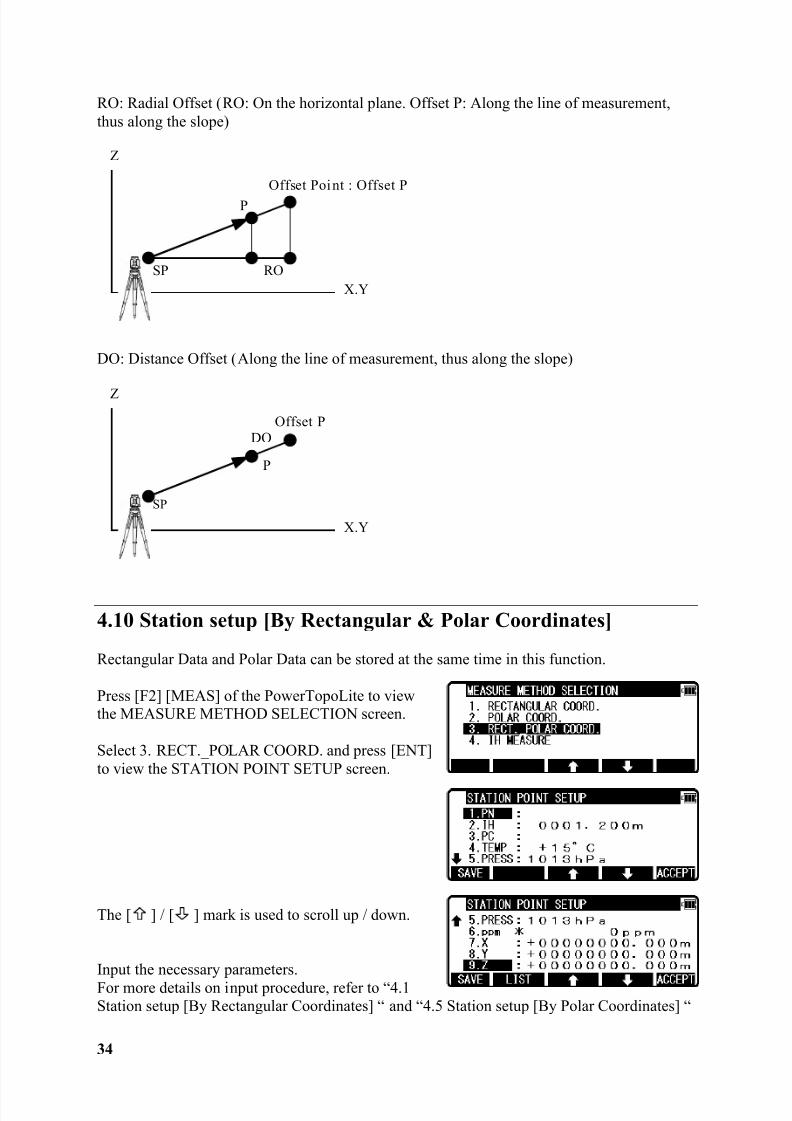
34
RO: Radial Offset (RO: On the horizontal plane. Offset P: Along the line of measurement,thus along the slope)
DO: Distance Offset (Along the line of measurement, thus along the slope)
4.10 Station setup [By Rectangular & Polar Coordinates]
Rectangular Data and Polar Data can be stored at the same time in this function.
Press [F2] [MEAS] of the PowerTopoLite to viewthe MEASURE METHOD SELECTION screen.
Select 3. RECT._POLAR COORD. and press [ENT]to view the STATION POINT SETUP screen.
The [ ] / [ ] mark is used to scroll up / down.
Input the necessary parameters.For more details on input procedure, refer to “4.1Station setup [By Rectangular Coordinates] “ and “4.5 Station setup [By Polar Coordinates] “
Z
SP RO
Offset Point : Offset P
X.Y
P
Z
SP
Offset PDO
X.Y
P
8/15/2019 r400v Man Ptl En
http://slidepdf.com/reader/full/r400v-man-ptl-en 36/142
35
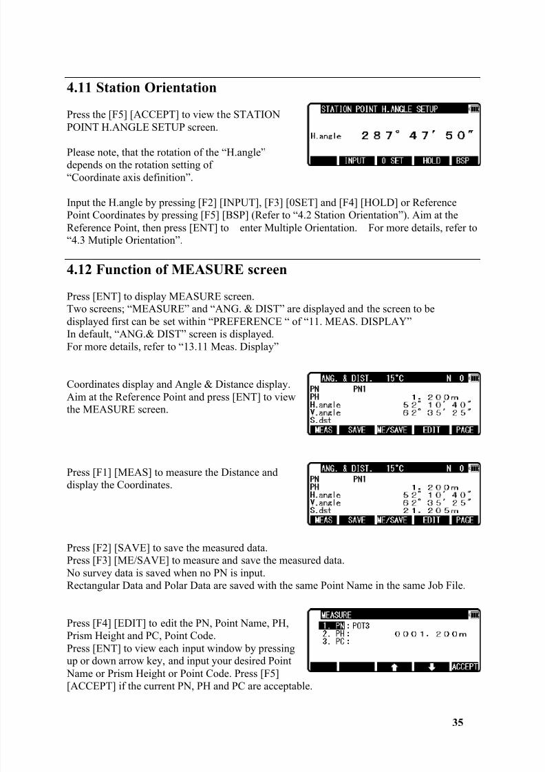
4.11 Station Orientation
Press the [F5] [ACCEPT] to view the STATIONPOINT H.ANGLE SETUP screen.
Please note, that the rotation of the “H.angle”depends on the rotation setting of“Coordinate axis definition”.
Input the H.angle by pressing [F2] [INPUT], [F3] [0SET] and [F4] [HOLD] or ReferencePoint Coordinates by pressing [F5] [BSP] (Refer to “4.2 Station Orientation”). Aim at theReference Point, then press [ENT] to enter Multiple Orientation. For more details, refer to“4.3 Mutiple Orientation”.
4.12 Function of MEASURE screenPress [ENT] to display MEASURE screen.Two screens; “MEASURE” and “ANG. & DIST” are displayed and the screen to bedisplayed first can be set within “PREFERENCE “ of “11. MEAS. DISPLAY”In default, “ANG.& DIST” screen is displayed.For more details, refer to “13.11 Meas. Display”
Coordinates display and Angle & Distance display.Aim at the Reference Point and press [ENT] to viewthe MEASURE screen.
Press [F1] [MEAS] to measure the Distance anddisplay the Coordinates.
Press [F2] [SAVE] to save the measured data.Press [F3] [ME/SAVE] to measure and save the measured data. No survey data is saved when no PN is input.Rectangular Data and Polar Data are saved with the same Point Name in the same Job File.
Press [F4] [EDIT] to edit the PN, Point Name, PH,Prism Height and PC, Point Code.Press [ENT] to view each input window by pressingup or down arrow key, and input your desired Point
Name or Prism Height or Point Code. Press [F5][ACCEPT] if the current PN, PH and PC are acceptable.
8/15/2019 r400v Man Ptl En
http://slidepdf.com/reader/full/r400v-man-ptl-en 37/142
36
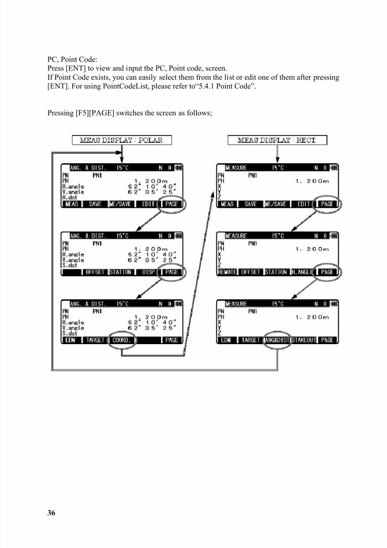
PC, Point Code:Press [ENT] to view and input the PC, Point code, screen.If Point Code exists, you can easily select them from the list or edit one of them after pressing[ENT]. For using PointCodeList, please refer to“5.4.1 Point Code”.
Pressing [F5][PAGE] switches the screen as follows;
8/15/2019 r400v Man Ptl En
http://slidepdf.com/reader/full/r400v-man-ptl-en 38/142
37
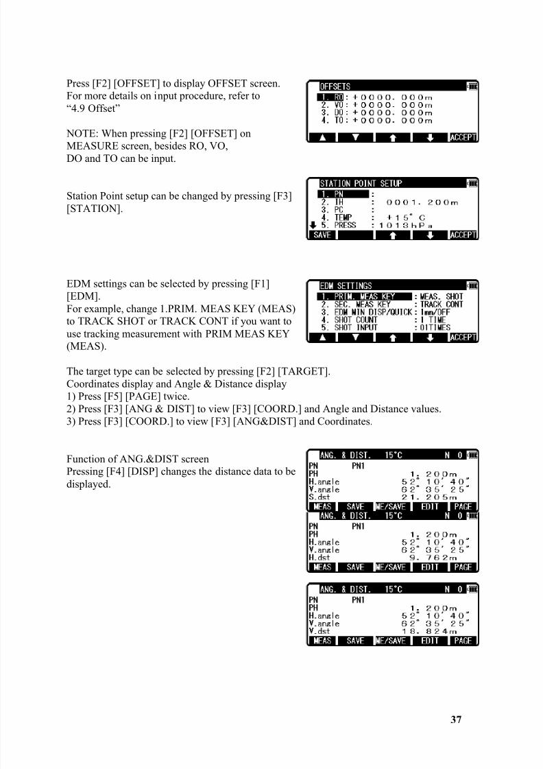
Press [F2] [OFFSET] to display OFFSET screen.For more details on input procedure, refer to“4.9 Offset”
NOTE: When pressing [F2] [OFFSET] onMEASURE screen, besides RO, VO,DO and TO can be input.
Station Point setup can be changed by pressing [F3][STATION].
EDM settings can be selected by pressing [F1][EDM].For example, change 1.PRIM. MEAS KEY (MEAS)to TRACK SHOT or TRACK CONT if you want touse tracking measurement with PRIM MEAS KEY(MEAS).
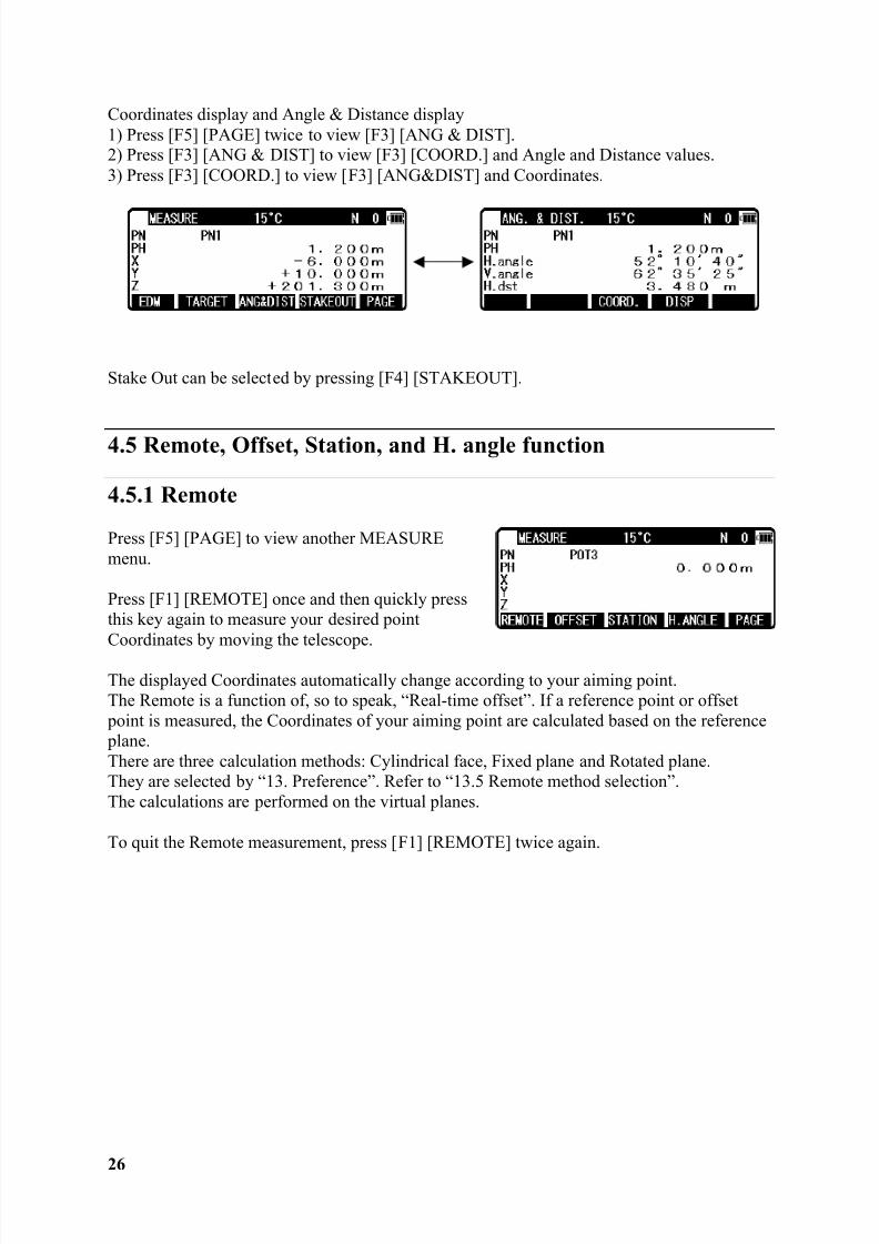
The target type can be selected by pressing [F2] [TARGET].Coordinates display and Angle & Distance display1) Press [F5] [PAGE] twice.2) Press [F3] [ANG & DIST] to view [F3] [COORD.] and Angle and Distance values.3) Press [F3] [COORD.] to view [F3] [ANG&DIST] and Coordinates.
Function of ANG.&DIST screenPressing [F4] [DISP] changes the distance data to bedisplayed.
8/15/2019 r400v Man Ptl En
http://slidepdf.com/reader/full/r400v-man-ptl-en 39/142
38
Function of MEASURE screen:
Press [F1] [REMOTE] to carry out Remote measurement (Refer to “4.5.1 Remote”)
Press [F4] [H.ANGLE] to display STATION POINT H. ANGLE SETUP (Refer to “4.2Station Orientation”)
Stake Out can be selected by pressing [F4][STAKEOUT].
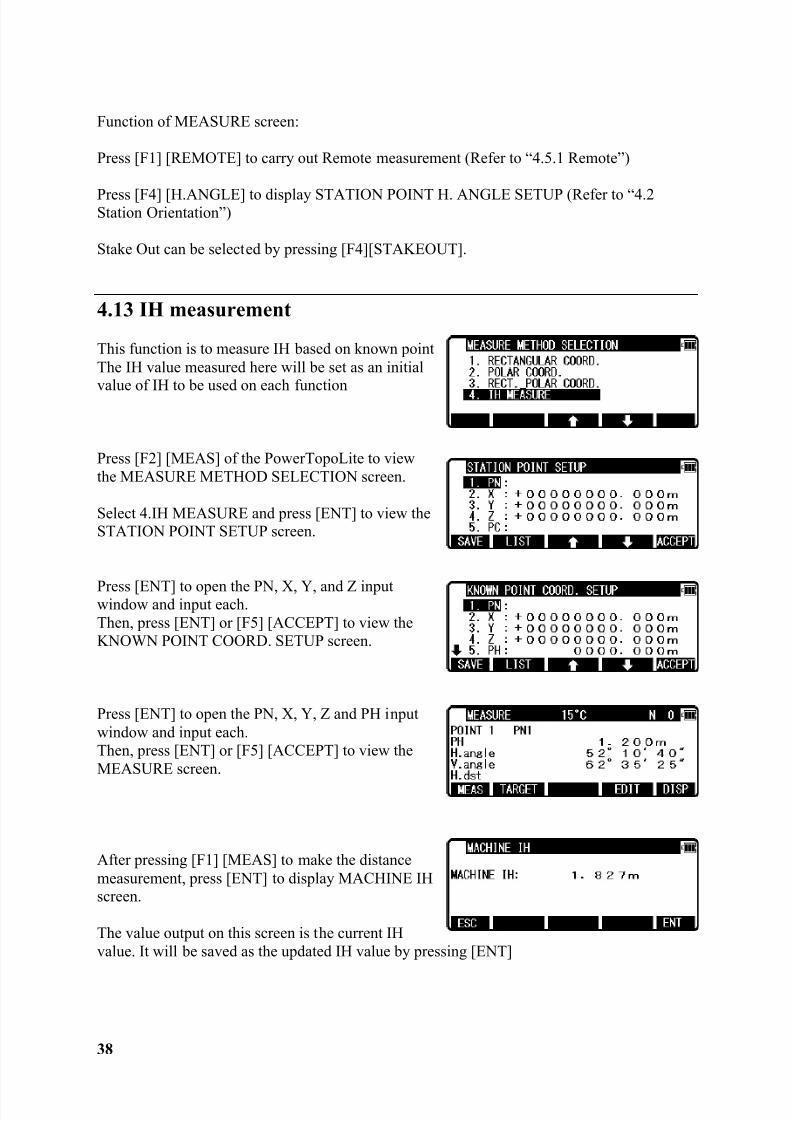
4.13 IH measurement
This function is to measure IH based on known pointThe IH value measured here will be set as an initial
value of IH to be used on each function
Press [F2] [MEAS] of the PowerTopoLite to viewthe MEASURE METHOD SELECTION screen.
Select 4.IH MEASURE and press [ENT] to view theSTATION POINT SETUP screen.
Press [ENT] to open the PN, X, Y, and Z inputwindow and input each.Then, press [ENT] or [F5] [ACCEPT] to view theKNOWN POINT COORD. SETUP screen.
Press [ENT] to open the PN, X, Y, Z and PH inputwindow and input each.Then, press [ENT] or [F5] [ACCEPT] to view theMEASURE screen.
After pressing [F1] [MEAS] to make the distancemeasurement, press [ENT] to display MACHINE IHscreen.
The value output on this screen is the current IHvalue. It will be saved as the updated IH value by pressing [ENT]
8/15/2019 r400v Man Ptl En
http://slidepdf.com/reader/full/r400v-man-ptl-en 40/142
39
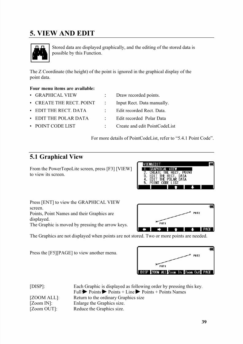
5. VIEW AND EDIT
Stored data are displayed graphically, and the editing of the stored data is possible by this Function.
The Z Coordinate (the height) of the point is ignored in the graphical display of the point data.
Four menu items are available:• GRAPHICAL VIEW Draw recorded points.
• CREATE THE RECT. POINT Input Rect. Data manually.
• EDIT THE RECT. DATA Edit recorded Rect. Data.
• EDIT THE POLAR DATA Edit recorded Polar Data• POINT CODE LIST Create and edit PointCodeList
For more details of PointCodeList, refer to “5.4.1 Point Code”.
5.1 Graphical View
From the PowerTopoLite screen, press [F3] [VIEW]to view its screen.
Press [ENT] to view the GRAPHICAL VIEWscreen.Points, Point Names and their Graphics aredisplayed.The Graphic is moved by pressing the arrow keys.
The Graphics are not displayed when points are not stored. Two or more points are needed.
Press the [F5][PAGE] to view another menu.
[DISP]: Each Graphic is displayed as following order by pressing this key.Full Points Points + Line Points + Points Names
[ZOOM ALL]: Return to the ordinary Graphics size[Zoom IN]: Enlarge the Graphics size.[Zoom OUT]: Reduce the Graphics size.
8/15/2019 r400v Man Ptl En
http://slidepdf.com/reader/full/r400v-man-ptl-en 41/142
40
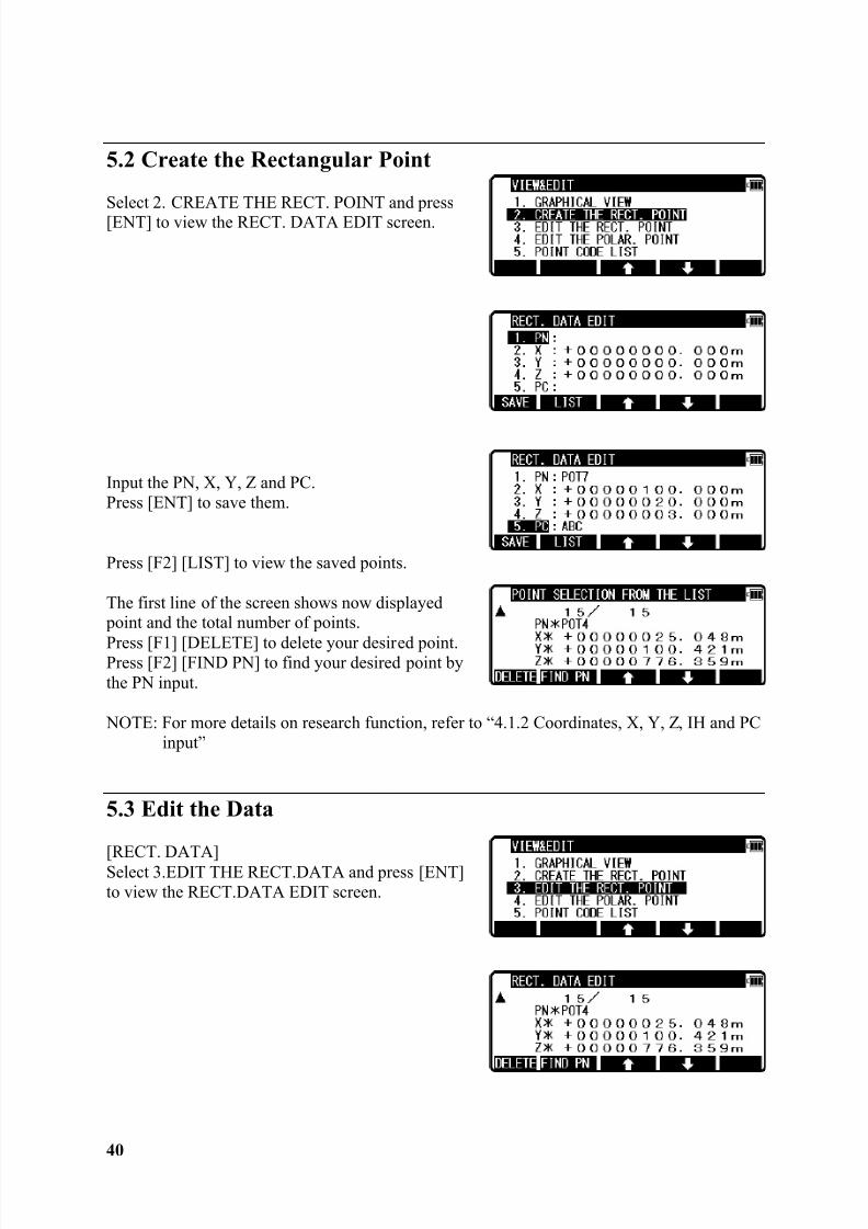
5.2 Create the Rectangular Point
Select 2. CREATE THE RECT. POINT and press[ENT] to view the RECT. DATA EDIT screen.
Input the PN, X, Y, Z and PC.Press [ENT] to save them.
Press [F2] [LIST] to view the saved points.
The first line of the screen shows now displayed point and the total number of points.
Press [F1] [DELETE] to delete your desired point.Press [F2] [FIND PN] to find your desired point bythe PN input.
NOTE: For more details on research function, refer to “4.1.2 Coordinates, X, Y, Z, IH and PCinput”
5.3 Edit the Data
[RECT. DATA]Select 3.EDIT THE RECT.DATA and press [ENT]to view the RECT.DATA EDIT screen.
8/15/2019 r400v Man Ptl En
http://slidepdf.com/reader/full/r400v-man-ptl-en 42/142
41
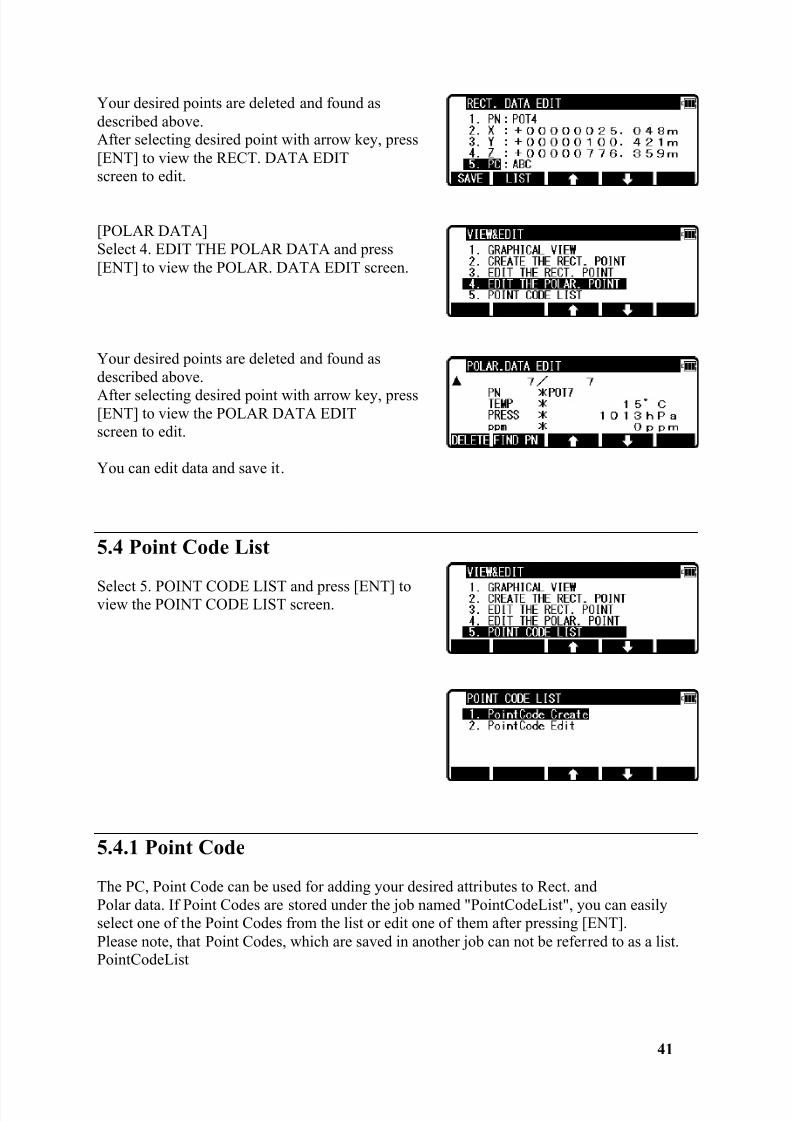
Your desired points are deleted and found asdescribed above.After selecting desired point with arrow key, press[ENT] to view the RECT. DATA EDITscreen to edit.
[POLAR DATA]Select 4. EDIT THE POLAR DATA and press[ENT] to view the POLAR. DATA EDIT screen.
Your desired points are deleted and found asdescribed above.After selecting desired point with arrow key, press[ENT] to view the POLAR DATA EDITscreen to edit.
You can edit data and save it.
5.4 Point Code List
Select 5. POINT CODE LIST and press [ENT] toview the POINT CODE LIST screen.
5.4.1 Point Code
The PC, Point Code can be used for adding your desired attributes to Rect. andPolar data. If Point Codes are stored under the job named "PointCodeList", you can easilyselect one of the Point Codes from the list or edit one of them after pressing [ENT].Please note, that Point Codes, which are saved in another job can not be referred to as a list.PointCodeList
8/15/2019 r400v Man Ptl En
http://slidepdf.com/reader/full/r400v-man-ptl-en 43/142
8/15/2019 r400v Man Ptl En
http://slidepdf.com/reader/full/r400v-man-ptl-en 44/142
43
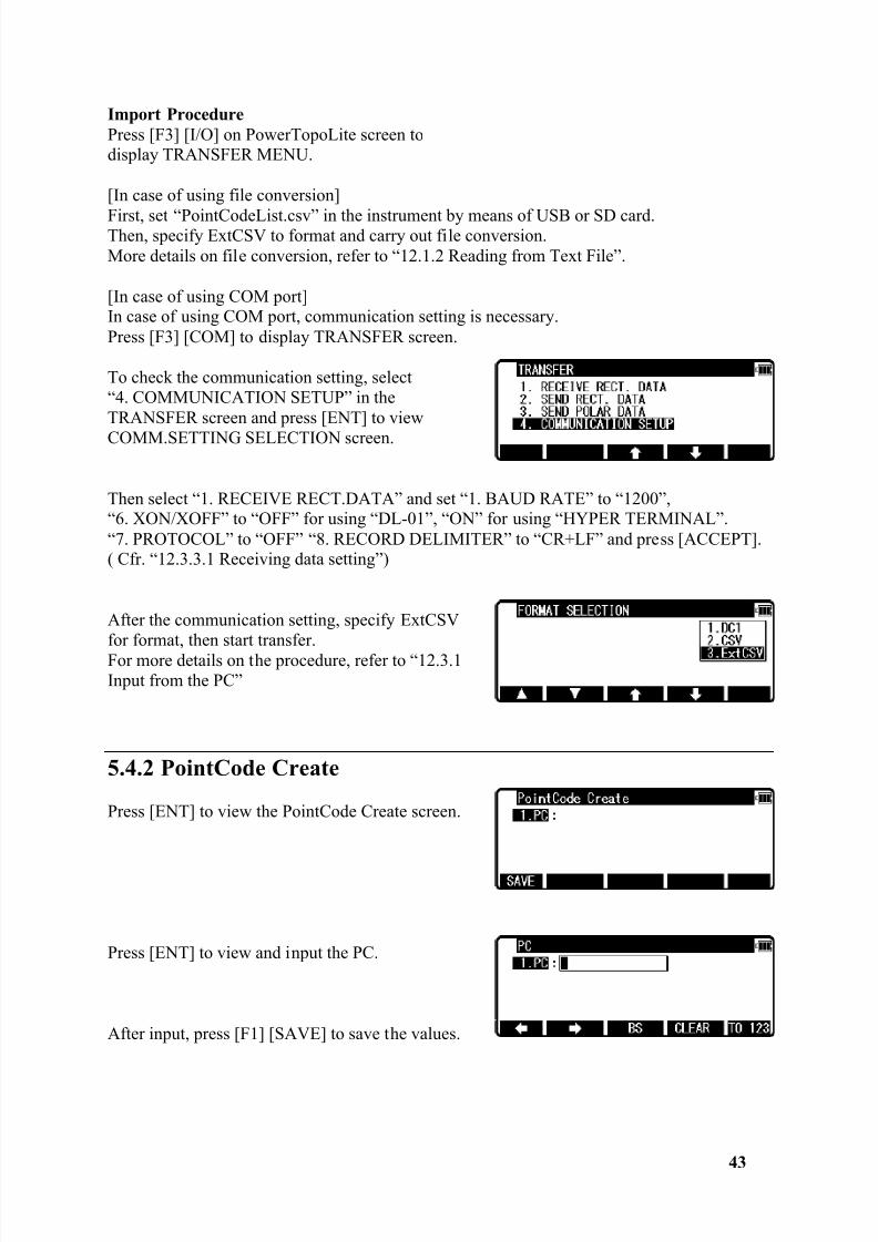
Import ProcedurePress [F3] [I/O] on PowerTopoLite screen todisplay TRANSFER MENU.
[In case of using file conversion]
First, set “PointCodeList.csv” in the instrument by means of USB or SD card.Then, specify ExtCSV to format and carry out file conversion.More details on file conversion, refer to “12.1.2 Reading from Text File”.
[In case of using COM port]In case of using COM port, communication setting is necessary.Press [F3] [COM] to display TRANSFER screen.
To check the communication setting, select“4. COMMUNICATION SETUP” in theTRANSFER screen and press [ENT] to viewCOMM.SETTING SELECTION screen.
Then select “1. RECEIVE RECT.DATA” and set “1. BAUD RATE” to “1200”,“6. XON/XOFF” to “OFF” for using “DL-01”, “ON” for using “HYPER TERMINAL”.“7. PROTOCOL” to “OFF” “8. RECORD DELIMITER” to “CR+LF” and press [ACCEPT].( Cfr. “12.3.3.1 Receiving data setting”)
After the communication setting, specify ExtCSVfor format, then start transfer.For more details on the procedure, refer to “12.3.1Input from the PC”
5.4.2 PointCode Create
Press [ENT] to view the PointCode Create screen.
Press [ENT] to view and input the PC.
After input, press [F1] [SAVE] to save the values.
8/15/2019 r400v Man Ptl En
http://slidepdf.com/reader/full/r400v-man-ptl-en 45/142
44
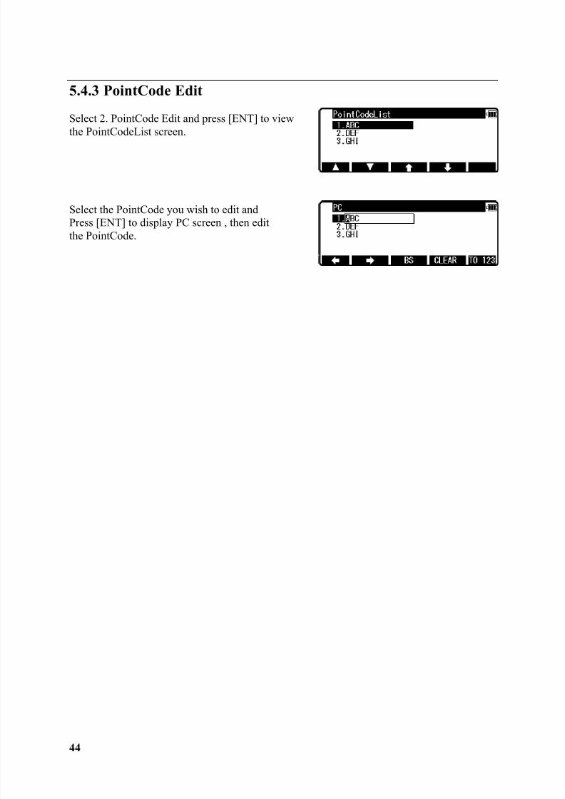
5.4.3 PointCode Edit
Select 2. PointCode Edit and press [ENT] to viewthe PointCodeList screen.
Select the PointCode you wish to edit andPress [ENT] to display PC screen , then editthe PointCode.
8/15/2019 r400v Man Ptl En
http://slidepdf.com/reader/full/r400v-man-ptl-en 46/142
45
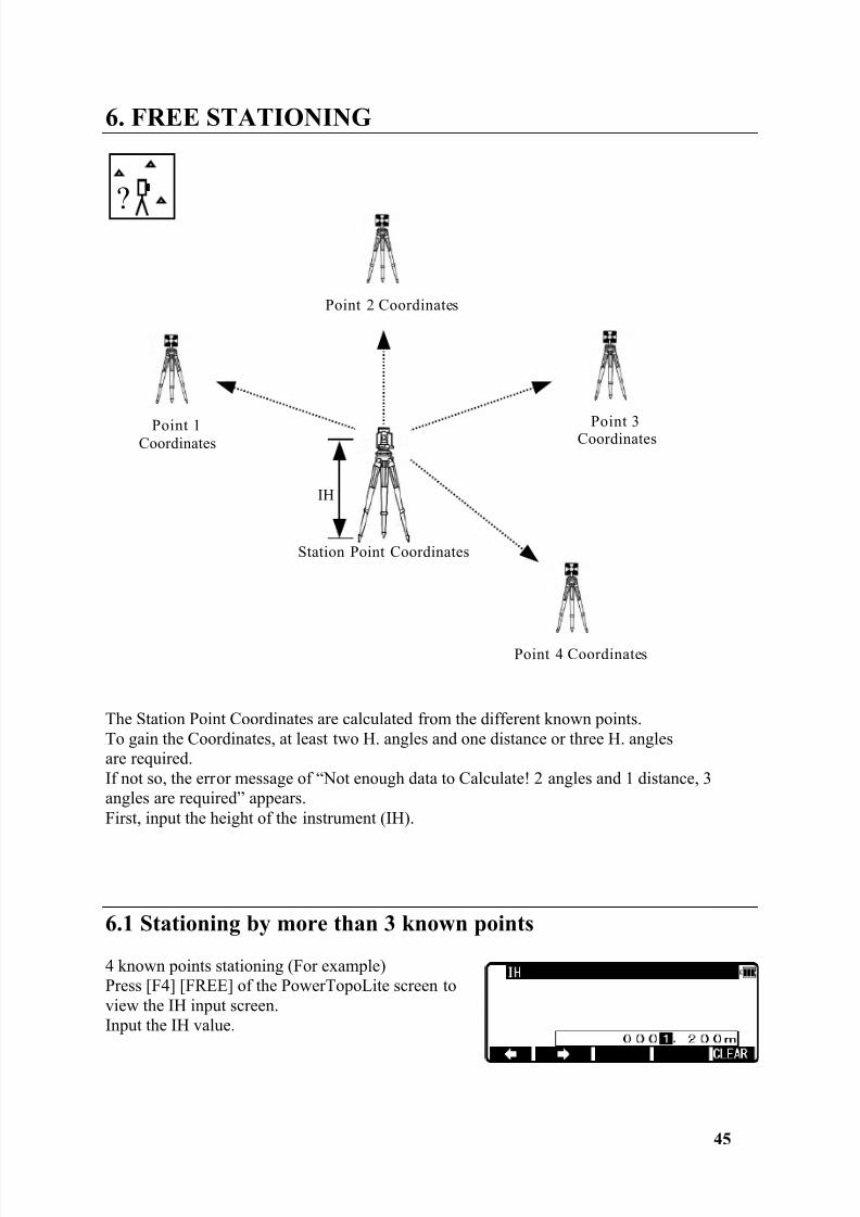
6. FREE STATIONING
The Station Point Coordinates are calculated from the different known points.To gain the Coordinates, at least two H. angles and one distance or three H. anglesare required.If not so, the error message of “Not enough data to Calculate! 2 angles and 1 distance, 3angles are required” appears.First, input the height of the instrument (IH).
6.1 Stationing by more than 3 known points
4 known points stationing (For example)Press [F4] [FREE] of the PowerTopoLite screen toview the IH input screen.Input the IH value.
?
Point 1Coordinates
Station Point Coordinates
Point 2 Coordinates
Point 3Coordinates
Point 4 Coordinates
IH

8/15/2019 r400v Man Ptl En
http://slidepdf.com/reader/full/r400v-man-ptl-en 47/142
8/15/2019 r400v Man Ptl En
http://slidepdf.com/reader/full/r400v-man-ptl-en 48/142
8/15/2019 r400v Man Ptl En
http://slidepdf.com/reader/full/r400v-man-ptl-en 49/142
48
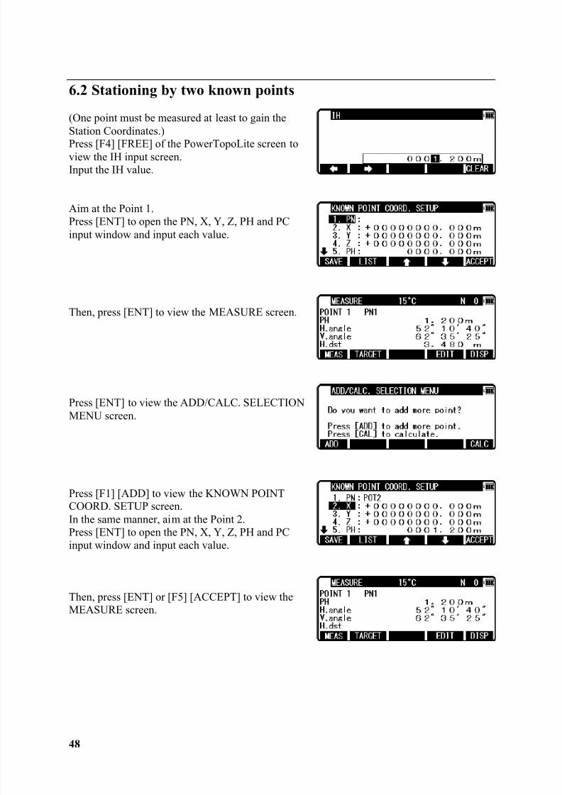
6.2 Stationing by two known points
(One point must be measured at least to gain theStation Coordinates.)Press [F4] [FREE] of the PowerTopoLite screen toview the IH input screen.Input the IH value.
Aim at the Point 1.Press [ENT] to open the PN, X, Y, Z, PH and PCinput window and input each value.
Then, press [ENT] to view the MEASURE screen.
Press [ENT] to view the ADD/CALC. SELECTION
MENU screen.
Press [F1] [ADD] to view the KNOWN POINTCOORD. SETUP screen.In the same manner, aim at the Point 2.Press [ENT] to open the PN, X, Y, Z, PH and PCinput window and input each value.
Then, press [ENT] or [F5] [ACCEPT] to view theMEASURE screen.
8/15/2019 r400v Man Ptl En
http://slidepdf.com/reader/full/r400v-man-ptl-en 50/142
49
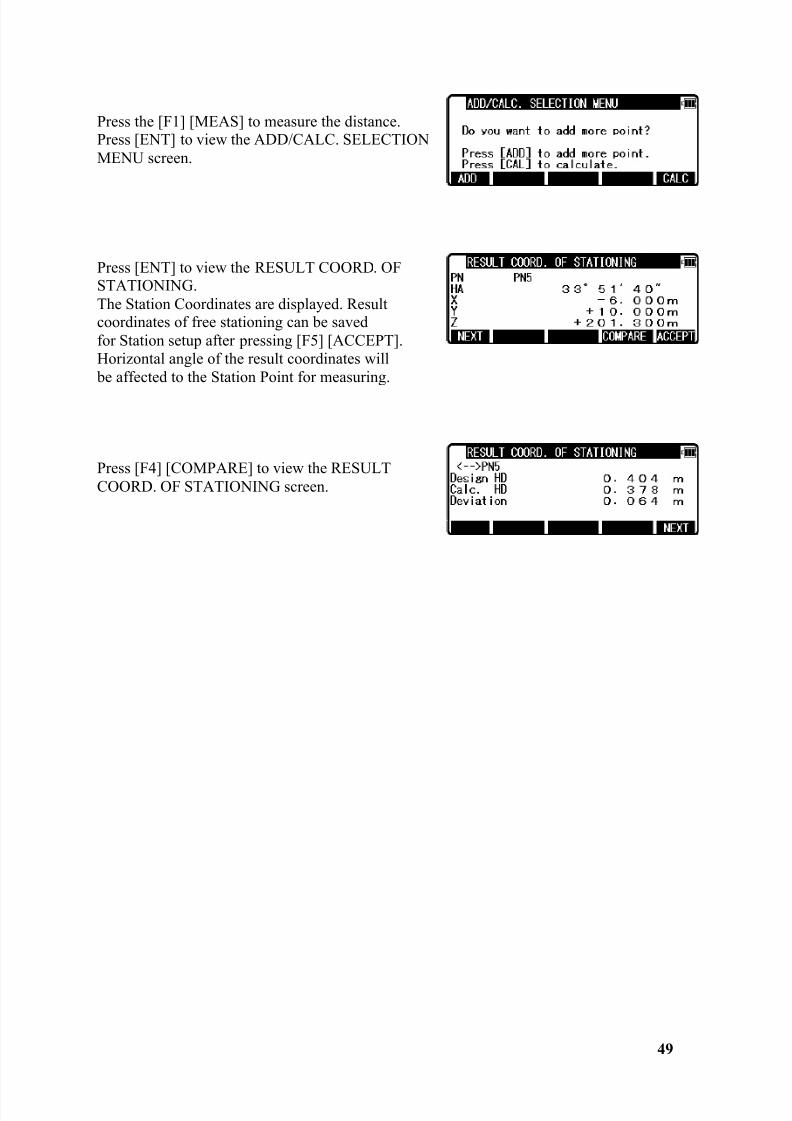
Press the [F1] [MEAS] to measure the distance.Press [ENT] to view the ADD/CALC. SELECTIONMENU screen.
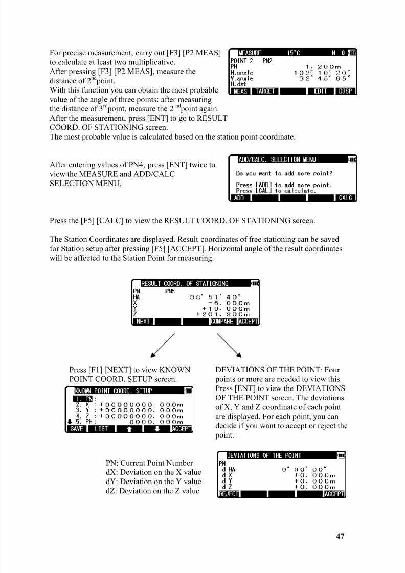
Press [ENT] to view the RESULT COORD. OFSTATIONING.The Station Coordinates are displayed. Resultcoordinates of free stationing can be savedfor Station setup after pressing [F5] [ACCEPT].Horizontal angle of the result coordinates will be affected to the Station Point for measuring.
Press [F4] [COMPARE] to view the RESULTCOORD. OF STATIONING screen.
8/15/2019 r400v Man Ptl En
http://slidepdf.com/reader/full/r400v-man-ptl-en 51/142
50
NOTE:
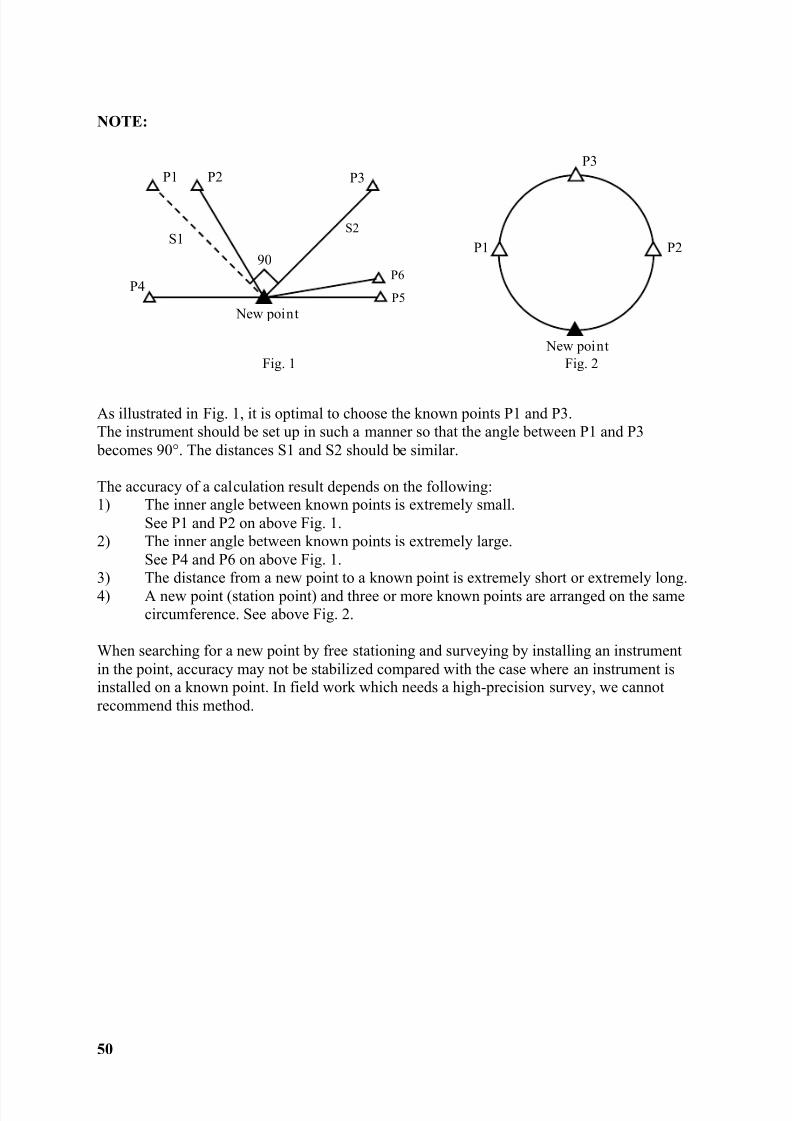
As illustrated in Fig. 1, it is optimal to choose the known points P1 and P3.The instrument should be set up in such a manner so that the angle between P1 and P3 becomes 90°. The distances S1 and S2 should be similar.
The accuracy of a calculation result depends on the following:1) The inner angle between known points is extremely small.
See P1 and P2 on above Fig. 1.2) The inner angle between known points is extremely large.
See P4 and P6 on above Fig. 1.3) The distance from a new point to a known point is extremely short or extremely long.4) A new point (station point) and three or more known points are arranged on the same
circumference. See above Fig. 2.
When searching for a new point by free stationing and surveying by installing an instrumentin the point, accuracy may not be stabilized compared with the case where an instrument isinstalled on a known point. In field work which needs a high-precision survey, we cannotrecommend this method.
P1
P3
New point
P4P5
P6
P2P1
S1S2
90
Fig. 1 Fig. 2 New point
P2
P3
8/15/2019 r400v Man Ptl En
http://slidepdf.com/reader/full/r400v-man-ptl-en 52/142
8/15/2019 r400v Man Ptl En
http://slidepdf.com/reader/full/r400v-man-ptl-en 53/142
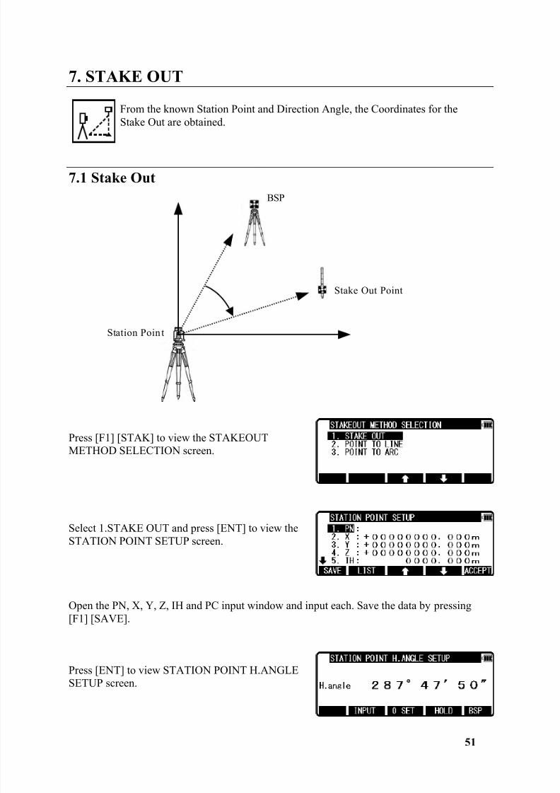
52
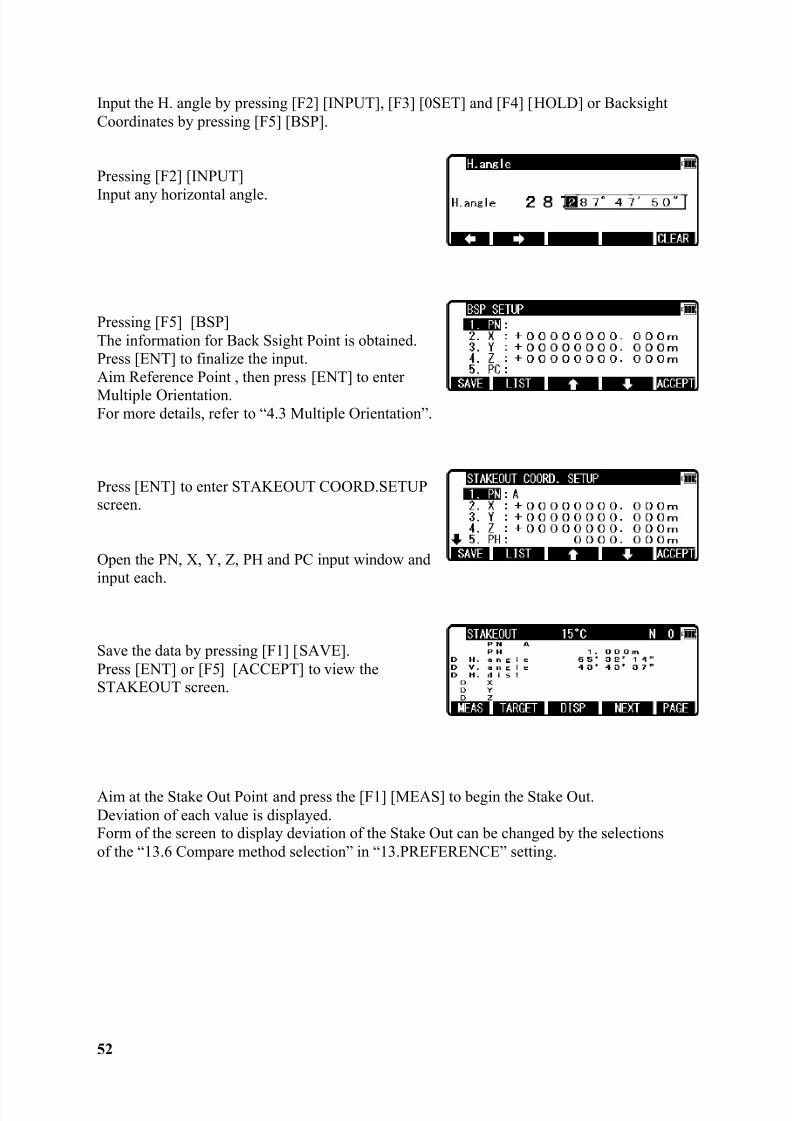
Input the H. angle by pressing [F2] [INPUT], [F3] [0SET] and [F4] [HOLD] or BacksightCoordinates by pressing [F5] [BSP].
Pressing [F2] [INPUT]
Input any horizontal angle.
Pressing [F5] [BSP]The information for Back Ssight Point is obtained.Press [ENT] to finalize the input.Aim Reference Point , then press [ENT] to enterMultiple Orientation.For more details, refer to “4.3 Multiple Orientation”.
Press [ENT] to enter STAKEOUT COORD.SETUPscreen.
Open the PN, X, Y, Z, PH and PC input window andinput each.
Save the data by pressing [F1] [SAVE].Press [ENT] or [F5] [ACCEPT] to view theSTAKEOUT screen.
Aim at the Stake Out Point and press the [F1] [MEAS] to begin the Stake Out.Deviation of each value is displayed.Form of the screen to display deviation of the Stake Out can be changed by the selectionsof the “13.6 Compare method selection” in “13.PREFERENCE” setting.
8/15/2019 r400v Man Ptl En
http://slidepdf.com/reader/full/r400v-man-ptl-en 54/142
8/15/2019 r400v Man Ptl En
http://slidepdf.com/reader/full/r400v-man-ptl-en 55/142
54
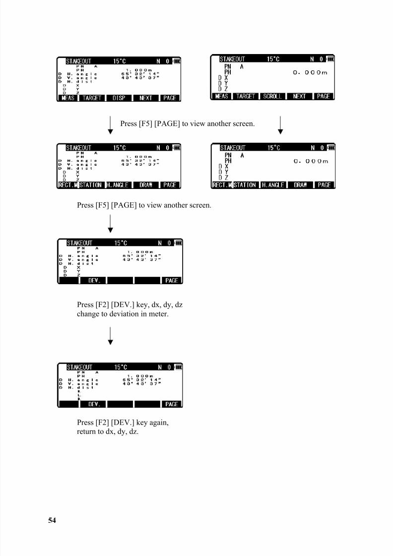
Press [F5] [PAGE] to view another screen.
Press [F5] [PAGE] to view another screen.
Press [F2] [DEV.] key, dx, dy, dzchange to deviation in meter.
Press [F2] [DEV.] key again,return to dx, dy, dz.
8/15/2019 r400v Man Ptl En
http://slidepdf.com/reader/full/r400v-man-ptl-en 56/142
55
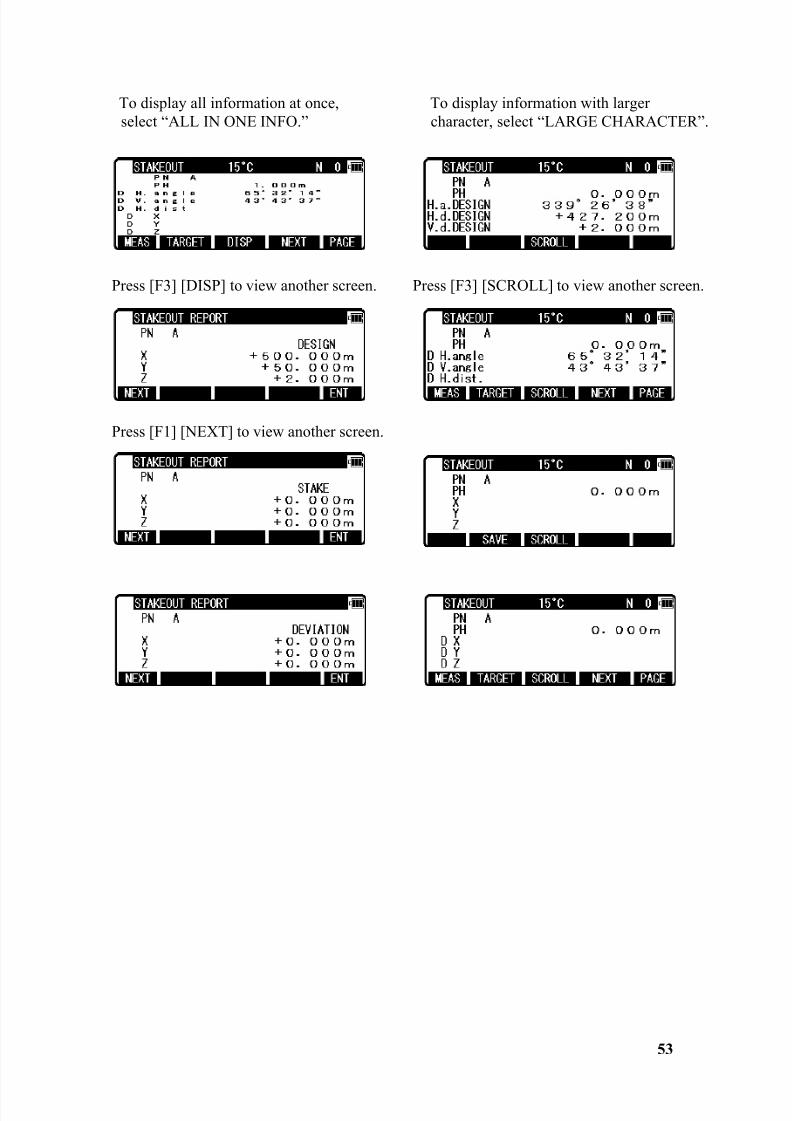
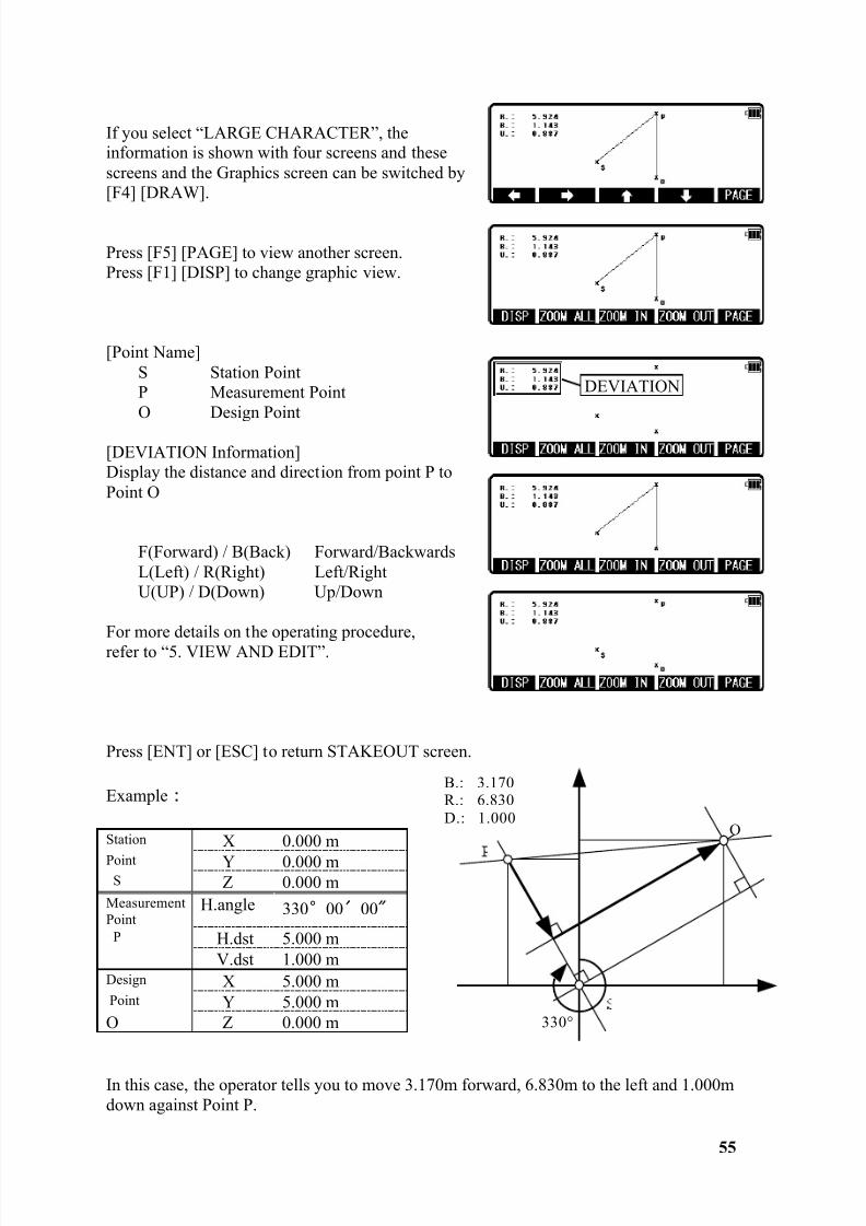
If you select “LARGE CHARACTER”, theinformation is shown with four screens and thesescreens and the Graphics screen can be switched by[F4] [DRAW].
Press [F5] [PAGE] to view another screen.Press [F1] [DISP] to change graphic view.
[Point Name]S Station PointP Measurement PointO Design Point
[DEVIATION Information]Display the distance and direction from point P toPoint O
F(Forward) / B(Back) Forward/BackwardsL(Left) / R(Right) Left/RightU(UP) / D(Down) Up/Down
For more details on the operating procedure,refer to “5. VIEW AND EDIT”.
Press [ENT] or [ESC] to return STAKEOUT screen.
Example
In this case, the operator tells you to move 3.170m forward, 6.830m to the left and 1.000mdown against Point P.
Station X 0.000 mPoint Y 0.000 m
S Z 0.000 mMeasurementPoint
H.angle 330 00 00
P H.dst 5.000 mV.dst 1.000 m
Design X 5.000 mPoint Y 5.000 mO Z 0.000 m
DEVIATION
B.: 3.170R.: 6.830D.: 1.000
O
330°
8/15/2019 r400v Man Ptl En
http://slidepdf.com/reader/full/r400v-man-ptl-en 57/142
56
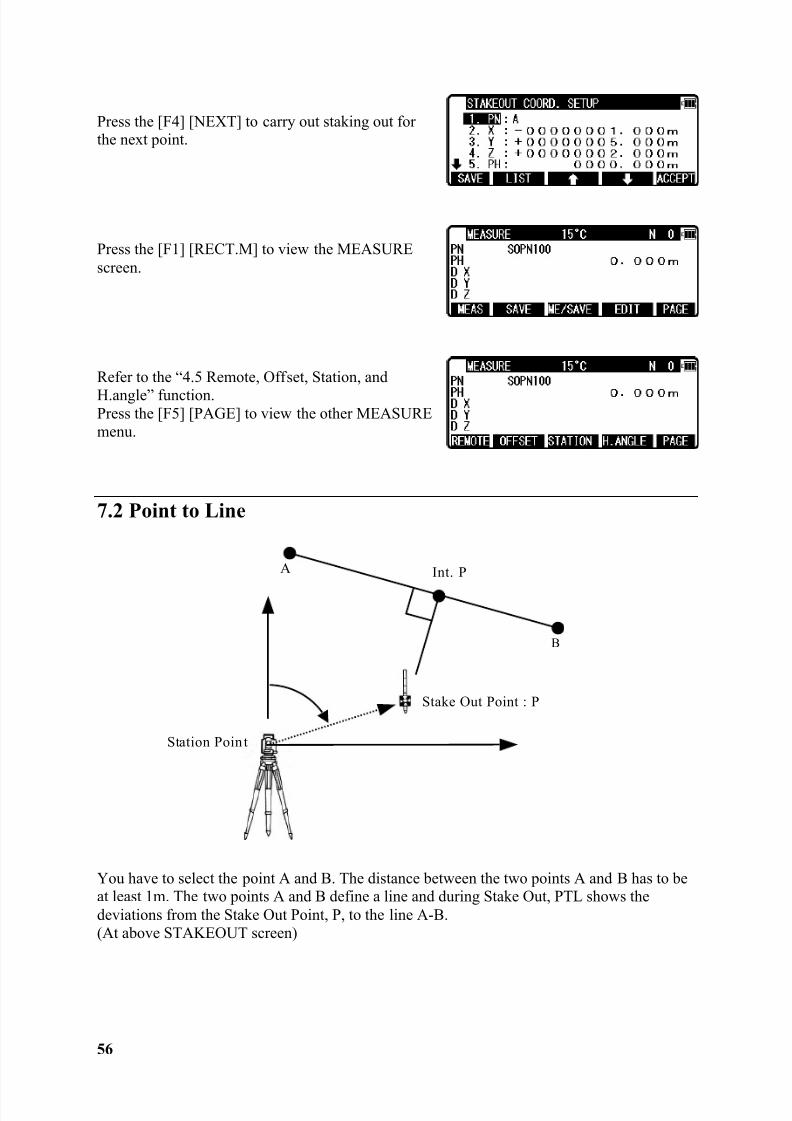
Press the [F4] [NEXT] to carry out staking out forthe next point.
Press the [F1] [RECT.M] to view the MEASUREscreen.
Refer to the “4.5 Remote, Offset, Station, andH.angle” function.Press the [F5] [PAGE] to view the other MEASUREmenu.
7.2 Point to Line
You have to select the point A and B. The distance between the two points A and B has to beat least 1m. The two points A and B define a line and during Stake Out, PTL shows thedeviations from the Stake Out Point, P, to the line A-B.(At above STAKEOUT screen)
Stake Out Point : P
Station Poin t
A Int. P
B
8/15/2019 r400v Man Ptl En
http://slidepdf.com/reader/full/r400v-man-ptl-en 58/142
57
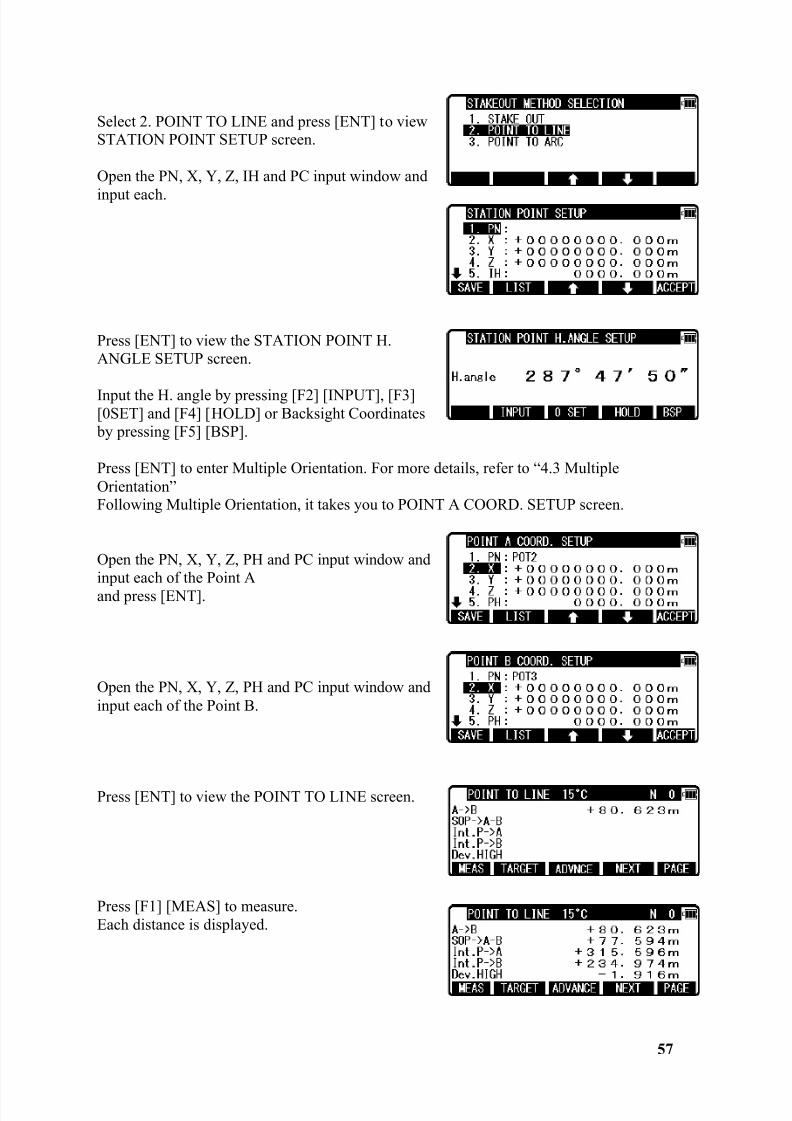
Select 2. POINT TO LINE and press [ENT] to viewSTATION POINT SETUP screen.
Open the PN, X, Y, Z, IH and PC input window and
input each.
Press [ENT] to view the STATION POINT H.ANGLE SETUP screen.
Input the H. angle by pressing [F2] [INPUT], [F3][0SET] and [F4] [HOLD] or Backsight Coordinates by pressing [F5] [BSP].
Press [ENT] to enter Multiple Orientation. For more details, refer to “4.3 MultipleOrientation”Following Multiple Orientation, it takes you to POINT A COORD. SETUP screen.
Open the PN, X, Y, Z, PH and PC input window andinput each of the Point Aand press [ENT].
Open the PN, X, Y, Z, PH and PC input window andinput each of the Point B.
Press [ENT] to view the POINT TO LINE screen.
Press [F1] [MEAS] to measure.Each distance is displayed.
8/15/2019 r400v Man Ptl En
http://slidepdf.com/reader/full/r400v-man-ptl-en 59/142
58
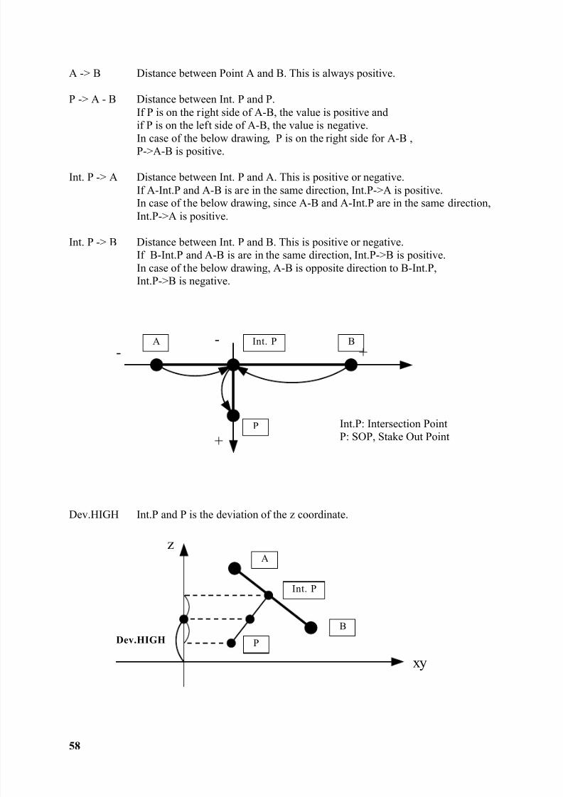
A -> B Distance between Point A and B. This is always positive.
P -> A - B Distance between Int. P and P.If P is on the right side of A-B, the value is positive andif P is on the left side of A-B, the value is negative.
In case of the below drawing, P is on the right side for A-B ,P->A-B is positive.
Int. P -> A Distance between Int. P and A. This is positive or negative.If A-Int.P and A-B is are in the same direction, Int.P->A is positive.In case of the below drawing, since A-B and A-Int.P are in the same direction,Int.P->A is positive.
Int. P -> B Distance between Int. P and B. This is positive or negative.If B-Int.P and A-B is are in the same direction, Int.P->B is positive.In case of the below drawing, A-B is opposite direction to B-Int.P,Int.P->B is negative.
Int.P: Intersection PointP: SOP, Stake Out Point
Dev.HIGH Int.P and P is the deviation of the z coordinate.
-
+
A B
P
Int. P- +
xy
A
B
P
Int. P
z
Dev.HIGH
8/15/2019 r400v Man Ptl En
http://slidepdf.com/reader/full/r400v-man-ptl-en 60/142
59
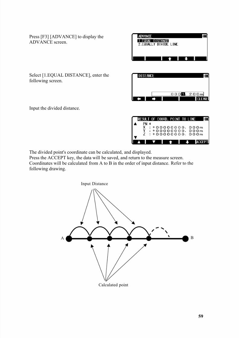
Press [F3] [ADVANCE] to display theADVANCE screen.
Select [1.EQUAL DISTANCE], enter thefollowing screen.
Input the divided distance.
The divided point's coordinate can be calculated, and displayed.Press the ACCEPT key, the data will be saved, and return to the measure screen.Coordinates will be calculated from A to B in the order of input distance. Refer to thefollowing drawing.
Calculated point
Input Distance
B
A
8/15/2019 r400v Man Ptl En
http://slidepdf.com/reader/full/r400v-man-ptl-en 61/142
60
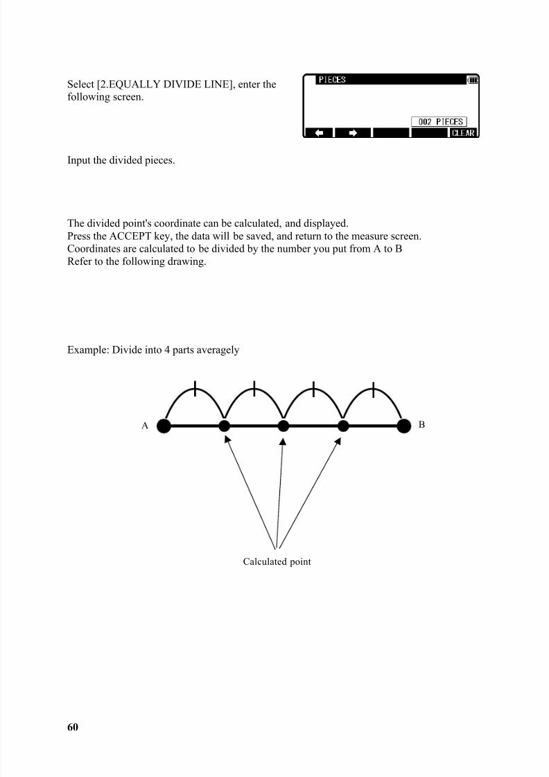
Select [2.EQUALLY DIVIDE LINE], enter thefollowing screen.
Input the divided pieces.
The divided point's coordinate can be calculated, and displayed.Press the ACCEPT key, the data will be saved, and return to the measure screen.Coordinates are calculated to be divided by the number you put from A to BRefer to the following drawing.
Example: Divide into 4 parts averagely
Calculated point
B
A
8/15/2019 r400v Man Ptl En
http://slidepdf.com/reader/full/r400v-man-ptl-en 62/142
8/15/2019 r400v Man Ptl En
http://slidepdf.com/reader/full/r400v-man-ptl-en 63/142
8/15/2019 r400v Man Ptl En
http://slidepdf.com/reader/full/r400v-man-ptl-en 64/142
8/15/2019 r400v Man Ptl En
http://slidepdf.com/reader/full/r400v-man-ptl-en 65/142
64
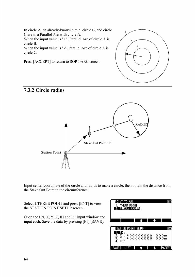
In circle A, an already-known circle, circle B, and circleC are in a Parallel Arc with circle A.When the input value is "+", Parallel Arc of circle A iscircle B.
When the input value is "-", Parallel Arc of circle A iscircle C.
Press [ACCEPT] to return to SOP->ARC screen.
7.3.2 Circle radius
Input center coordinate of the circle and radius to make a circle, then obtain the distance fromthe Stake Out Point to the circumference.
Select 1.THREE POINT and press [ENT] to viewthe STATION POINT SETUP screen.
Open the PN, X, Y, Z, IH and PC input window andinput each. Save the data by pressing [F1] [SAVE].
Stake Out Point : P
Station Poin t
RADIUS
CP
8/15/2019 r400v Man Ptl En
http://slidepdf.com/reader/full/r400v-man-ptl-en 66/142
65
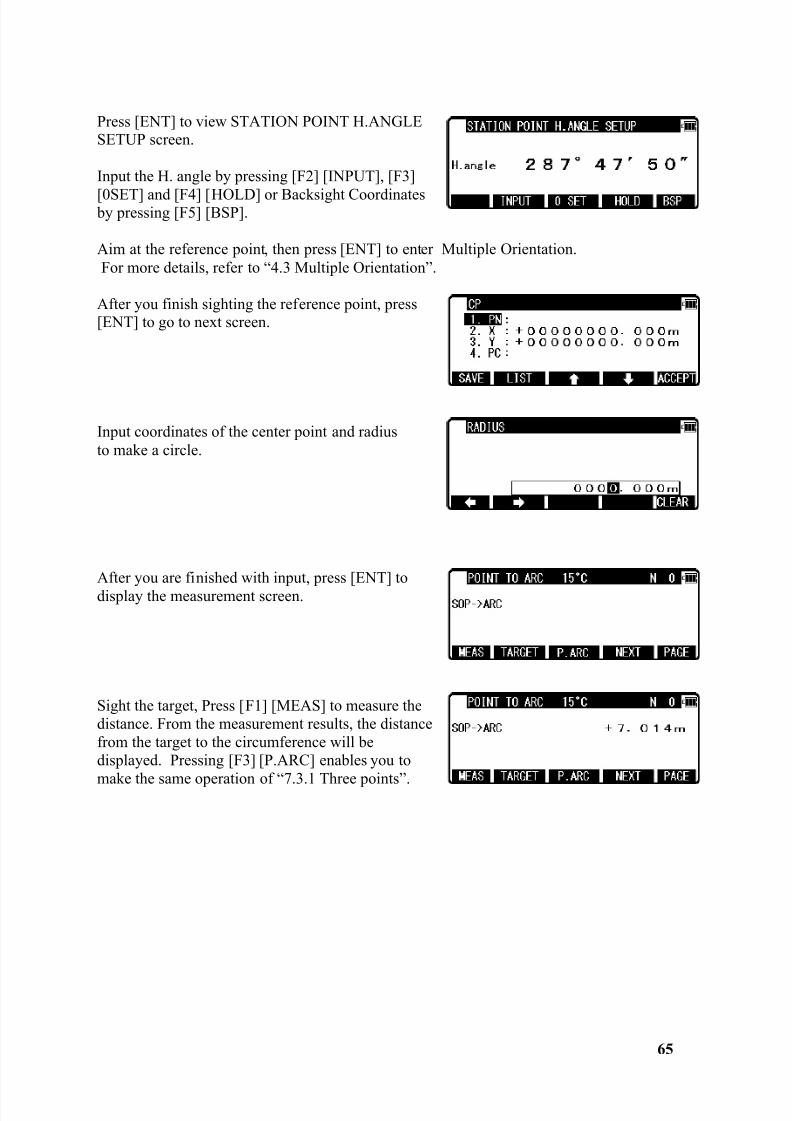
Press [ENT] to view STATION POINT H.ANGLESETUP screen.
Input the H. angle by pressing [F2] [INPUT], [F3]
[0SET] and [F4] [HOLD] or Backsight Coordinates by pressing [F5] [BSP].
Aim at the reference point, then press [ENT] to enter Multiple Orientation.For more details, refer to “4.3 Multiple Orientation”.
After you finish sighting the reference point, press[ENT] to go to next screen.
Input coordinates of the center point and radiusto make a circle.
After you are finished with input, press [ENT] todisplay the measurement screen.
Sight the target, Press [F1] [MEAS] to measure thedistance. From the measurement results, the distancefrom the target to the circumference will bedisplayed. Pressing [F3] [P.ARC] enables you to
make the same operation of “7.3.1 Three points”.
8/15/2019 r400v Man Ptl En
http://slidepdf.com/reader/full/r400v-man-ptl-en 67/142
66
8. CALCULATIONS
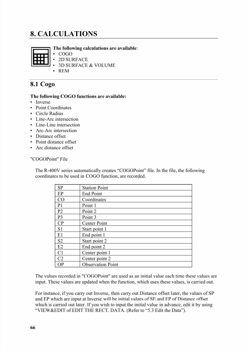
The following calculations are available :• COGO
• 2D SURFACE• 3D SURFACE & VOLUME• REM
8.1 Cogo
The following COGO functions are available:• Inverse• Point Coordinates• Circle Radius• Line-Arc intersection• Line-Line intersection• Arc-Arc intersection• Distance offset• Point distance offset• Arc distance offset
"COGOPoint" File
The R-400V series automatically creates “COGOPoint” file. In the file, the followingcoordinates to be used in COGO function, are recorded.
SP Station PointEP End PointCO CoordinatesP1 Point 1P2 Point 2P3 Point 3CP Center PointS1 Start point 1E1 End point 1S2 Start point 2E2 End point 2C1 Center point 1C2 Center point 2OP Observation Point
The values recorded in "COGOPoint" are used as an initial value each time these values areinput. These values are updated when the function, which uses these values, is carried out.
For instance, if you carry out Inverse, then carry out Distance offset later, the values of SPand EP which are input at Inverse will be initial values of SE and EP of Distance offset
which is carried out later. If you wish to input the initial value in advance, edit it by using“VIEW&EDIT of EDIT THE RECT. DATA. (Refer to “5.3 Edit the Data”).
8/15/2019 r400v Man Ptl En
http://slidepdf.com/reader/full/r400v-man-ptl-en 68/142
8/15/2019 r400v Man Ptl En
http://slidepdf.com/reader/full/r400v-man-ptl-en 69/142
68
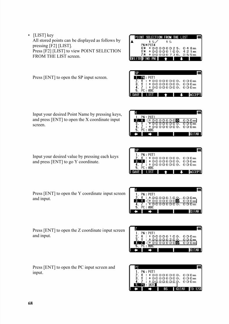
• [LIST] keyAll stored points can be displayed as follows by pressing [F2] [LIST].Press [F2] [LIST] to view POINT SELECTION
FROM THE LIST screen.
Press [ENT] to open the SP input screen.
Input your desired Point Name by pressing keys,and press [ENT] to open the X coordinate inputscreen.
Input your desired value by pressing each keysand press [ENT] to go Y coordinate.
Press [ENT] to open the Y coordinate input screenand input.
Press [ENT] to open the Z coordinate input screenand input.
Press [ENT] to open the PC input screen andinput.
8/15/2019 r400v Man Ptl En
http://slidepdf.com/reader/full/r400v-man-ptl-en 70/142
69
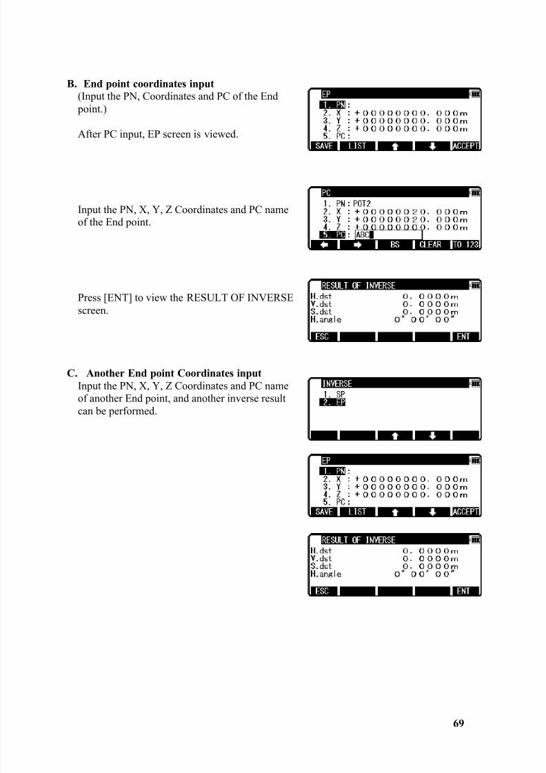
B. End point coordinates input(Input the PN, Coordinates and PC of the End point.)
After PC input, EP screen is viewed.
Input the PN, X, Y, Z Coordinates and PC nameof the End point.
Press [ENT] to view the RESULT OF INVERSEscreen.
C. Another End point Coordinates inputInput the PN, X, Y, Z Coordinates and PC nameof another End point, and another inverse resultcan be performed.
8/15/2019 r400v Man Ptl En
http://slidepdf.com/reader/full/r400v-man-ptl-en 71/142
70
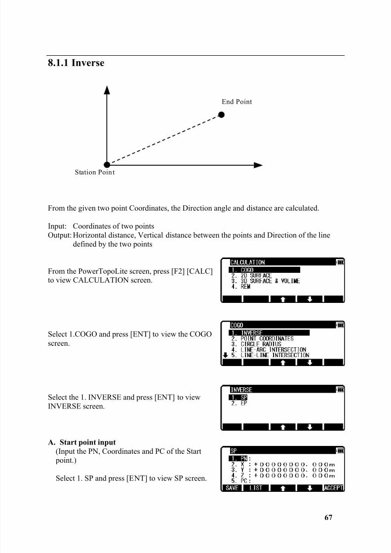
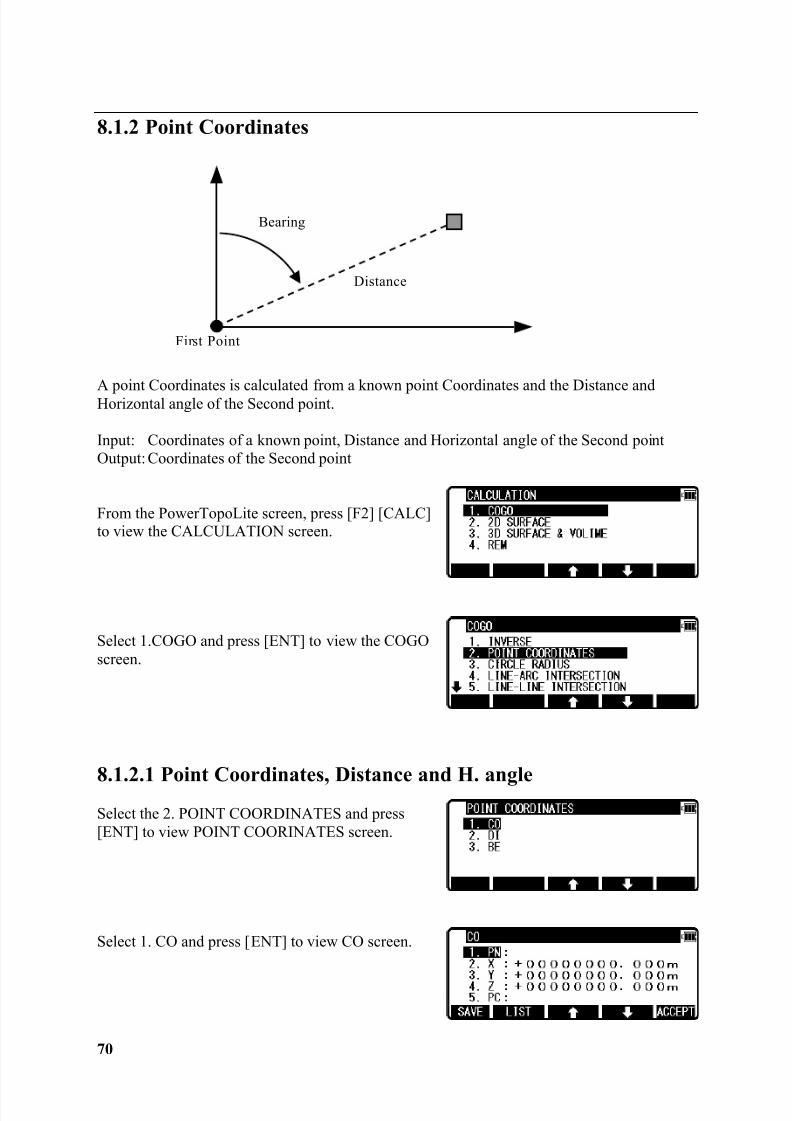
8.1.2 Point Coordinates
A point Coordinates is calculated from a known point Coordinates and the Distance andHorizontal angle of the Second point.
Input: Coordinates of a known point, Distance and Horizontal angle of the Second pointOutput: Coordinates of the Second point
From the PowerTopoLite screen, press [F2] [CALC]to view the CALCULATION screen.
Select 1.COGO and press [ENT] to view the COGOscreen.
8.1.2.1 Point Coordinates, Distance and H. angle
Select the 2. POINT COORDINATES and press[ENT] to view POINT COORINATES screen.
Select 1. CO and press [ENT] to view CO screen.
Distance
First Point
Bearing
8/15/2019 r400v Man Ptl En
http://slidepdf.com/reader/full/r400v-man-ptl-en 72/142
71
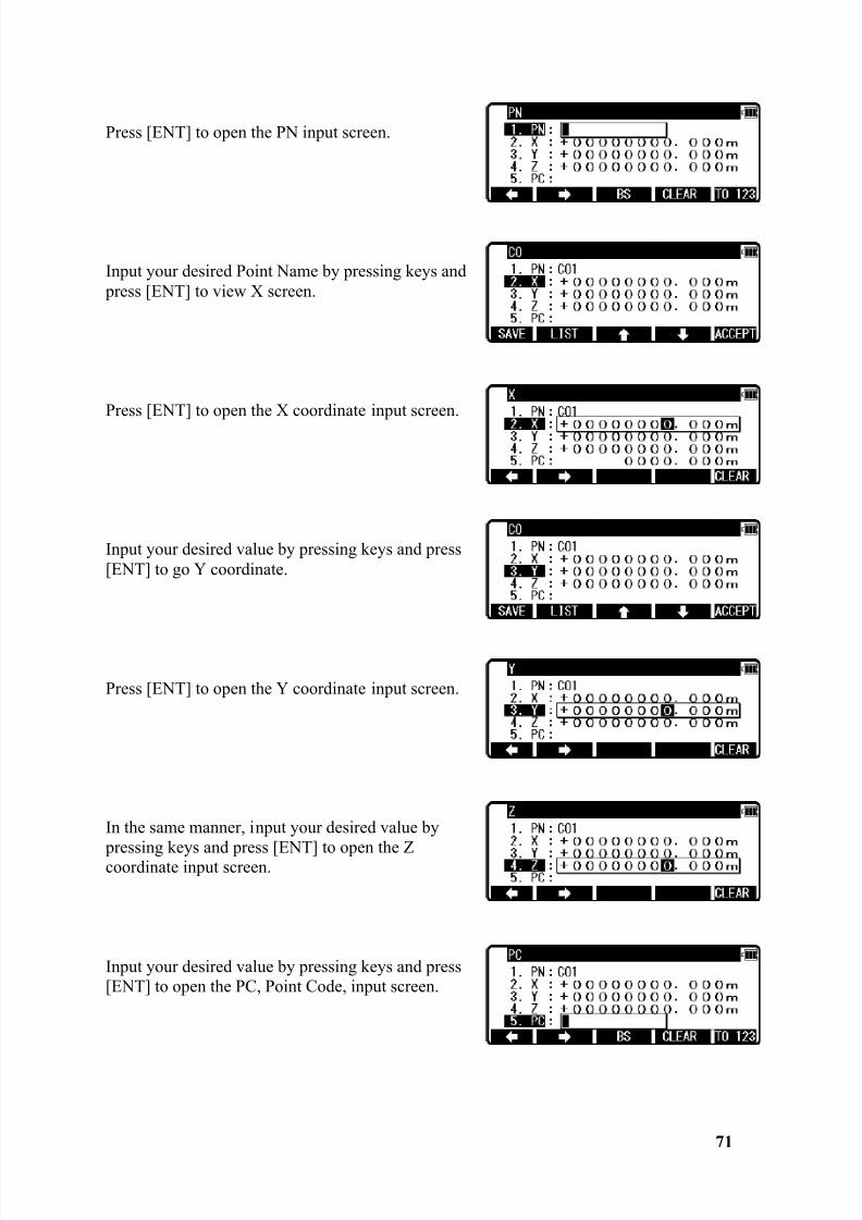
Press [ENT] to open the PN input screen.
Input your desired Point Name by pressing keys and press [ENT] to view X screen.
Press [ENT] to open the X coordinate input screen.
Input your desired value by pressing keys and press[ENT] to go Y coordinate.
Press [ENT] to open the Y coordinate input screen.
In the same manner, input your desired value by
pressing keys and press [ENT] to open the Zcoordinate input screen.
Input your desired value by pressing keys and press[ENT] to open the PC, Point Code, input screen.
8/15/2019 r400v Man Ptl En
http://slidepdf.com/reader/full/r400v-man-ptl-en 73/142
8/15/2019 r400v Man Ptl En
http://slidepdf.com/reader/full/r400v-man-ptl-en 74/142
73
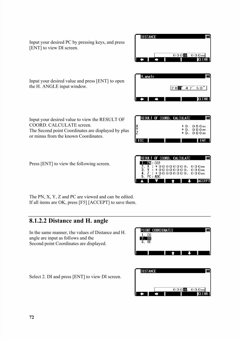
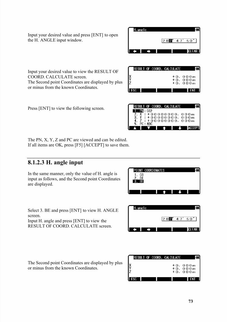
Input your desired value and press [ENT] to openthe H. ANGLE input window.
Input your desired value to view the RESULT OFCOORD. CALCULATE screen.The Second point Coordinates are displayed by plusor minus from the known Coordinates.
Press [ENT] to view the following screen.
The PN, X, Y, Z and PC are viewed and can be edited.If all items are OK, press [F5] [ACCEPT] to save them.
8.1.2.3 H. angle input
In the same manner, only the value of H. angle isinput as follows, and the Second point Coordinatesare displayed.
Select 3. BE and press [ENT] to view H. ANGLEscreen.Input H. angle and press [ENT] to view theRESULT OF COORD. CALCULATE screen.
The Second point Coordinates are displayed by plusor minus from the known Coordinates.
8/15/2019 r400v Man Ptl En
http://slidepdf.com/reader/full/r400v-man-ptl-en 75/142
74
Press [ENT] to view the following screen.
The PN, X, Y, Z and PC are viewed and can be edited.If all items are OK, press [F5] [ACCEPT] to save them.
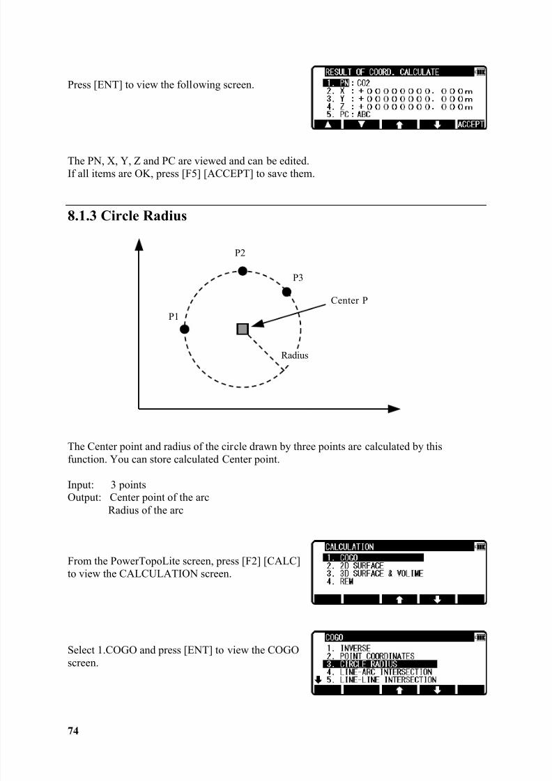
8.1.3 Circle Radius
The Center point and radius of the circle drawn by three points are calculated by thisfunction. You can store calculated Center point.
Input: 3 pointsOutput: Center point of the arc
Radius of the arc
From the PowerTopoLite screen, press [F2] [CALC]to view the CALCULATION screen.
Select 1.COGO and press [ENT] to view the COGOscreen.
Center P
Radius
P1
P2
P3
8/15/2019 r400v Man Ptl En
http://slidepdf.com/reader/full/r400v-man-ptl-en 76/142
75
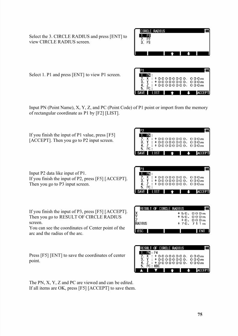
Select the 3. CIRCLE RADIUS and press [ENT] toview CIRCLE RADIUS screen.
Select 1. P1 and press [ENT] to view P1 screen.
Input PN (Point Name), X, Y, Z, and PC (Point Code) of P1 point or import from the memoryof rectangular coordinate as P1 by [F2] [LIST].
If you finish the input of P1 value, press [F5][ACCEPT]. Then you go to P2 input screen.
Input P2 data like input of P1.If you finish the input of P2, press [F5] [ACCEPT].Then you go to P3 input screen.
If you finish the input of P3, press [F5] [ACCEPT].Then you go to RESULT OF CIRCLE RADIUSscreen.You can see the coordinates of Center point of the
arc and the radius of the arc.
Press [F5] [ENT] to save the coordinates of center point.
The PN, X, Y, Z and PC are viewed and can be edited.If all items are OK, press [F5] [ACCEPT] to save them.
8/15/2019 r400v Man Ptl En
http://slidepdf.com/reader/full/r400v-man-ptl-en 77/142
76
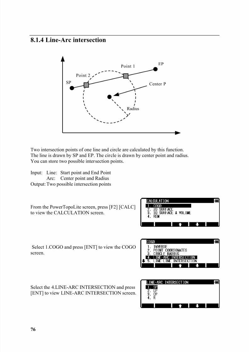
8.1.4 Line-Arc intersection
Two intersection points of one line and circle are calculated by this function.The line is drawn by SP and EP. The circle is drawn by center point and radius.You can store two possible intersection points.
Input: Line: Start point and End PointArc: Center point and Radius
Output: Two possible intersection points
From the PowerTopoLite screen, press [F2] [CALC]to view the CALCULATION screen.
Select 1.COGO and press [ENT] to view the COGOscreen.
Select the 4.LINE-ARC INTERSECTION and press[ENT] to view LINE-ARC INTERSECTION screen.
Center P
Radius
SP
Point 2
EPPoint 1
8/15/2019 r400v Man Ptl En
http://slidepdf.com/reader/full/r400v-man-ptl-en 78/142
77
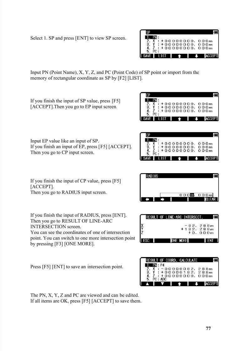
Select 1. SP and press [ENT] to view SP screen.
Input PN (Point Name), X, Y, Z, and PC (Point Code) of SP point or import from thememory of rectangular coordinate as SP by [F2] [LIST].
If you finish the input of SP value, press [F5][ACCEPT].Then you go to EP input screen.
Input EP value like an input of SP.If you finish an input of EP, press [F5] [ACCEPT].Then you go to CP input screen.
If you finish the input of CP value, press [F5][ACCEPT].Then you go to RADIUS input screen.
If you finish the input of RADIUS, press [ENT].Then you go to RESULT OF LINE-ARCINTERSECTION screen.You can see the coordinates of one of intersection point. You can switch to one more intersection point
by pressing [F3] [ONE MORE].
Press [F5] [ENT] to save an intersection point.
The PN, X, Y, Z and PC are viewed and can be edited.If all items are OK, press [F5] [ACCEPT] to save them.
8/15/2019 r400v Man Ptl En
http://slidepdf.com/reader/full/r400v-man-ptl-en 79/142
78
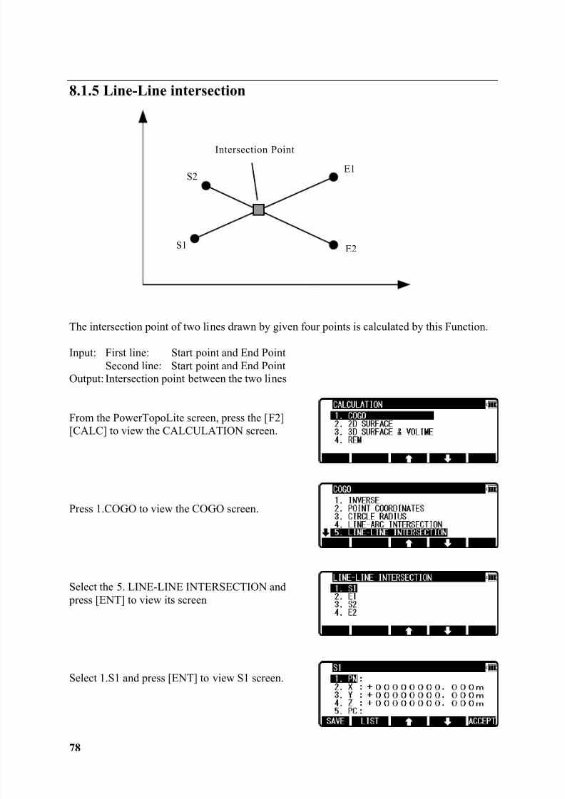
8.1.5 Line-Line intersection
The intersection point of two lines drawn by given four points is calculated by this Function.
Input: First line: Start point and End PointSecond line: Start point and End Point
Output: Intersection point between the two lines
From the PowerTopoLite screen, press the [F2][CALC] to view the CALCULATION screen.
Press 1.COGO to view the COGO screen.
Select the 5. LINE-LINE INTERSECTION and press [ENT] to view its screen
Select 1.S1 and press [ENT] to view S1 screen.
E2S1
S2
Intersection Point
E1
8/15/2019 r400v Man Ptl En
http://slidepdf.com/reader/full/r400v-man-ptl-en 80/142
79
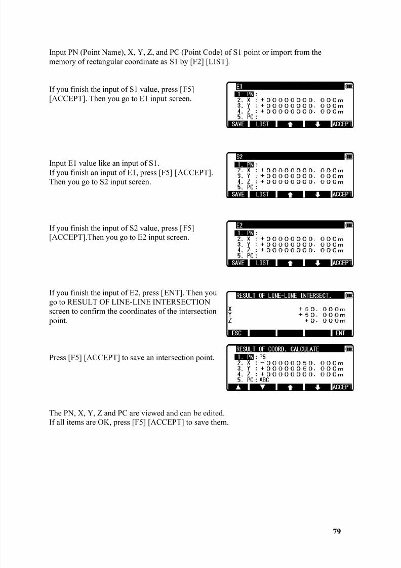
Input PN (Point Name), X, Y, Z, and PC (Point Code) of S1 point or import from thememory of rectangular coordinate as S1 by [F2] [LIST].
If you finish the input of S1 value, press [F5]
[ACCEPT]. Then you go to E1 input screen.
Input E1 value like an input of S1.If you finish an input of E1, press [F5] [ACCEPT].Then you go to S2 input screen.
If you finish the input of S2 value, press [F5][ACCEPT].Then you go to E2 input screen.
If you finish the input of E2, press [ENT]. Then yougo to RESULT OF LINE-LINE INTERSECTIONscreen to confirm the coordinates of the intersection point.
Press [F5] [ACCEPT] to save an intersection point.
The PN, X, Y, Z and PC are viewed and can be edited.If all items are OK, press [F5] [ACCEPT] to save them.
8/15/2019 r400v Man Ptl En
http://slidepdf.com/reader/full/r400v-man-ptl-en 81/142
80
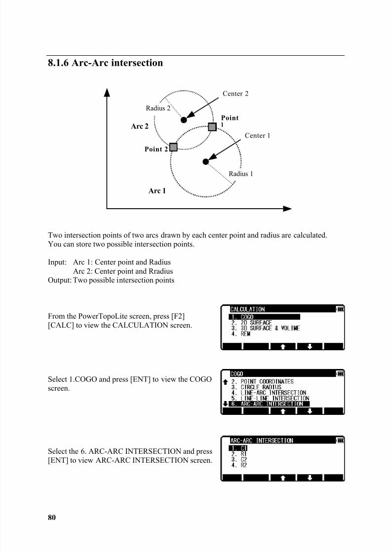
8.1.6 Arc-Arc intersection
Two intersection points of two arcs drawn by each center point and radius are calculated.You can store two possible intersection points.
Input: Arc 1: Center point and RadiusArc 2: Center point and Rradius
Output: Two possible intersection points
From the PowerTopoLite screen, press [F2][CALC] to view the CALCULATION screen.
Select 1.COGO and press [ENT] to view the COGOscreen.
Select the 6. ARC-ARC INTERSECTION and press[ENT] to view ARC-ARC INTERSECTION screen.
Center 2
PointRadius 2
Radius 1
Point 2
Arc 2
Arc 1
Center 1
8/15/2019 r400v Man Ptl En
http://slidepdf.com/reader/full/r400v-man-ptl-en 82/142
81
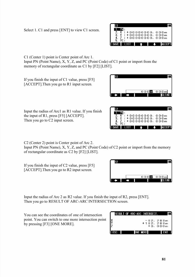
Select 1. C1 and press [ENT] to view C1 screen.
C1 (Center 1) point is Center point of Arc 1.Input PN (Point Name), X, Y, Z, and PC (Point Code) of C1 point or import from thememory of rectangular coordinate as C1 by [F2] [LIST].
If you finish the input of C1 value, press [F5][ACCEPT].Then you go to R1 input screen.
Input the radius of Arc1 as R1 value. If you finishthe input of R1, press [F5] [ACCEPT].Then you go to C2 input screen.
C2 (Center 2) point is Center point of Arc 2.Input PN (Point Name), X, Y, Z, and PC (Point Code) of C2 point or import from the memoryof rectangular coordinate as C2 by [F2] [LIST].
If you finish the input of C2 value, press [F5][ACCEPT].Then you go to R2 input screen.
Input the radius of Arc 2 as R2 value. If you finish the input of R2, press [ENT].Then you go to RESULT OF ARC-ARC INTERSECTION screen.
You can see the coordinates of one of intersection point. You can switch to one more intersection point by pressing [F3] [ONE MORE].
8/15/2019 r400v Man Ptl En
http://slidepdf.com/reader/full/r400v-man-ptl-en 83/142
82
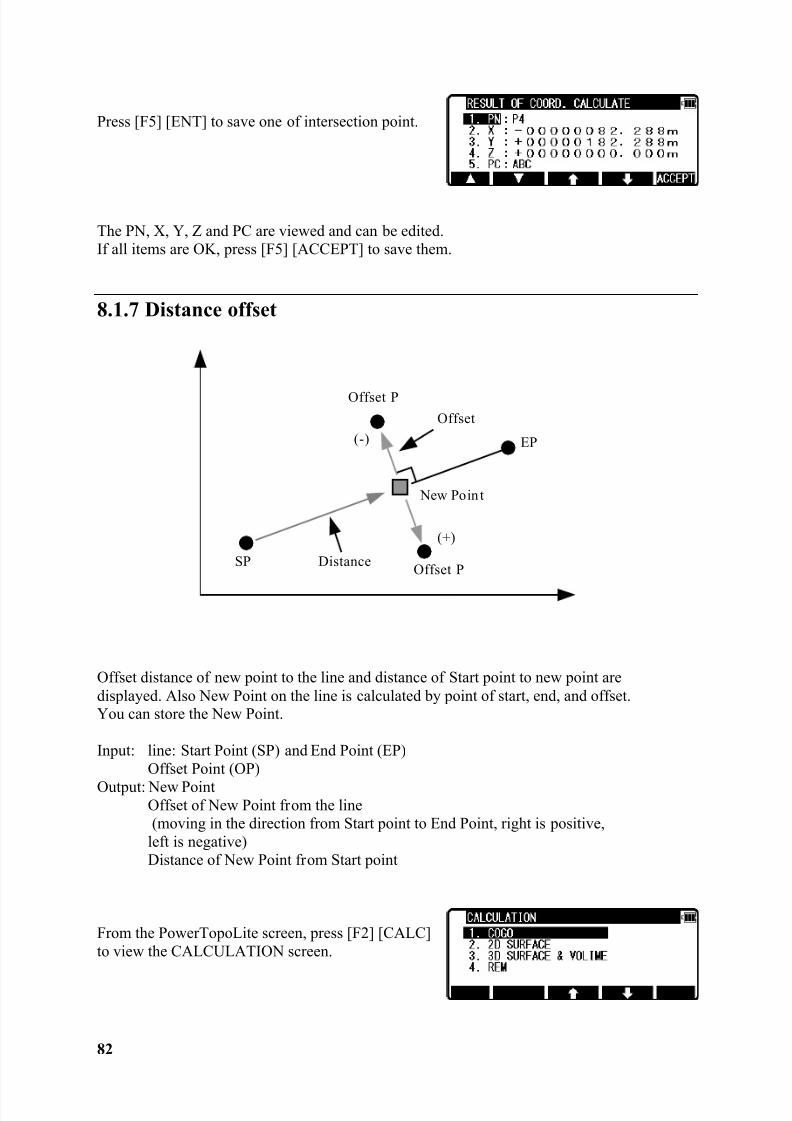
Press [F5] [ENT] to save one of intersection point.
The PN, X, Y, Z and PC are viewed and can be edited.If all items are OK, press [F5] [ACCEPT] to save them.
8.1.7 Distance offset
Offset distance of new point to the line and distance of Start point to new point aredisplayed. Also New Point on the line is calculated by point of start, end, and offset.You can store the New Point.
Input: line: Start Point (SP) and End Point (EP)Offset Point (OP)
Output: New PointOffset of New Point from the line(moving in the direction from Start point to End Point, right is positive,
left is negative)Distance of New Point from Start point
From the PowerTopoLite screen, press [F2] [CALC]to view the CALCULATION screen.
(+)
SP
EP
Offset P
New Poin t
Offset P
(-)Offset
Distance
8/15/2019 r400v Man Ptl En
http://slidepdf.com/reader/full/r400v-man-ptl-en 84/142
83
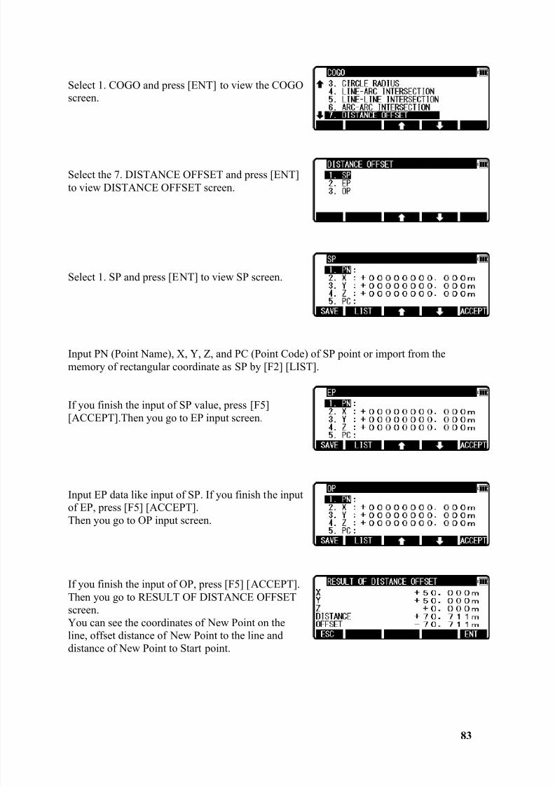
Select 1. COGO and press [ENT] to view the COGOscreen.
Select the 7. DISTANCE OFFSET and press [ENT]to view DISTANCE OFFSET screen.
Select 1. SP and press [ENT] to view SP screen.
Input PN (Point Name), X, Y, Z, and PC (Point Code) of SP point or import from thememory of rectangular coordinate as SP by [F2] [LIST].
If you finish the input of SP value, press [F5][ACCEPT].Then you go to EP input screen.
Input EP data like input of SP. If you finish the inputof EP, press [F5] [ACCEPT].Then you go to OP input screen.
If you finish the input of OP, press [F5] [ACCEPT].Then you go to RESULT OF DISTANCE OFFSETscreen.You can see the coordinates of New Point on theline, offset distance of New Point to the line anddistance of New Point to Start point.
8/15/2019 r400v Man Ptl En
http://slidepdf.com/reader/full/r400v-man-ptl-en 85/142
84
Press [F5] [ENT] to save the coordinates of new point.
The PN, X, Y, Z and PC are viewed and can be edited.If all items are OK, press [F5] [ACCEPT] to save them.
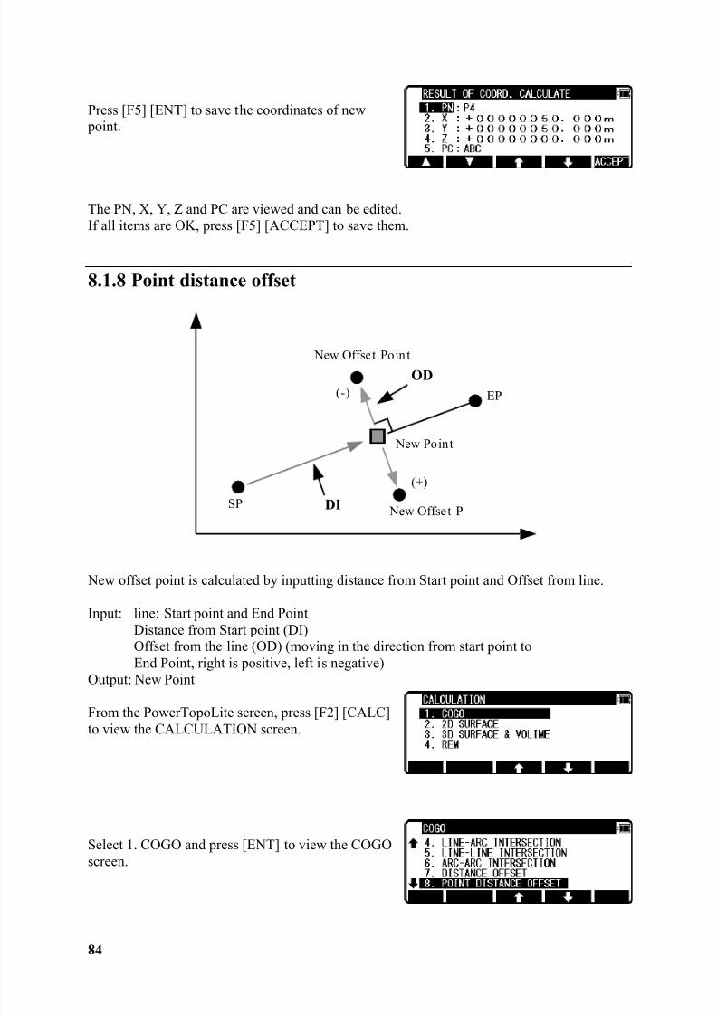
8.1.8 Point distance offset
New offset point is calculated by inputting distance from Start point and Offset from line.
Input: line: Start point and End PointDistance from Start point (DI)Offset from the line (OD) (moving in the direction from start point toEnd Point, right is positive, left is negative)
Output: New Point
From the PowerTopoLite screen, press [F2] [CALC]to view the CALCULATION screen.
Select 1. COGO and press [ENT] to view the COGOscreen.
(+)
SP
EP
New Offset Poin t
New Poin t
New Offset P
(-)OD
DI
8/15/2019 r400v Man Ptl En
http://slidepdf.com/reader/full/r400v-man-ptl-en 86/142
85
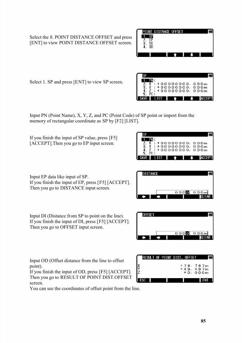
Select the 8. POINT DISTANCE OFFSET and press[ENT] to view POINT DISTANCE OFFSET screen.
Select 1. SP and press [ENT] to view SP screen.
Input PN (Point Name), X, Y, Z, and PC (Point Code) of SP point or import from thememory of rectangular coordinate as SP by [F2] [LIST].
If you finish the input of SP value, press [F5][ACCEPT].Then you go to EP input screen.
Input EP data like input of SP.If you finish the input of EP, press [F5] [ACCEPT].Then you go to DISTANCE input screen.
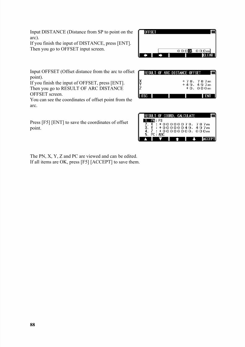
Input DI (Distance from SP to point on the line).If you finish the input of DI, press [F5] [ACCEPT].Then you go to OFFSET input screen.
Input OD (Offset distance from the line to offset point).If you finish the input of OD, press [F5] [ACCEPT].Then you go to RESULT OF POINT DIST.OFFSETscreen.You can see the coordinates of offset point from the line.
8/15/2019 r400v Man Ptl En
http://slidepdf.com/reader/full/r400v-man-ptl-en 87/142
86
Press [F5] [ENT] to save the coordinates of offset point.
The PN, X, Y, Z and PC are viewed and can be edited. If all items are OK, press [F5][ACCEPT] to save them.
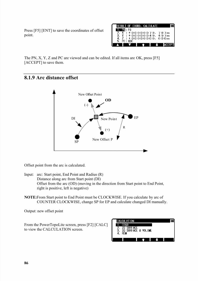
8.1.9 Arc distance offset
Offset point from the arc is calculated.
Input: arc: Start point, End Point and Radius (R)Distance along arc from Start point (DI)Offset from the arc (OD) (moving in the direction from Start point to End Point,right is positive, left is negative)
NOTE: From Start point to End Point must be CLOCKWISE. If you calculate by arc ofCOUNTER CLOCKWISE, change SP for EP and calculate changed DI manually.
Output: new offset point
From the PowerTopoLite screen, press [F2] [CALC]to view the CALCULATION screen.
(+)
SP
EP
New Offset Point
New Poin t
New Offset P
(-)OD
DI
R
8/15/2019 r400v Man Ptl En
http://slidepdf.com/reader/full/r400v-man-ptl-en 88/142
87
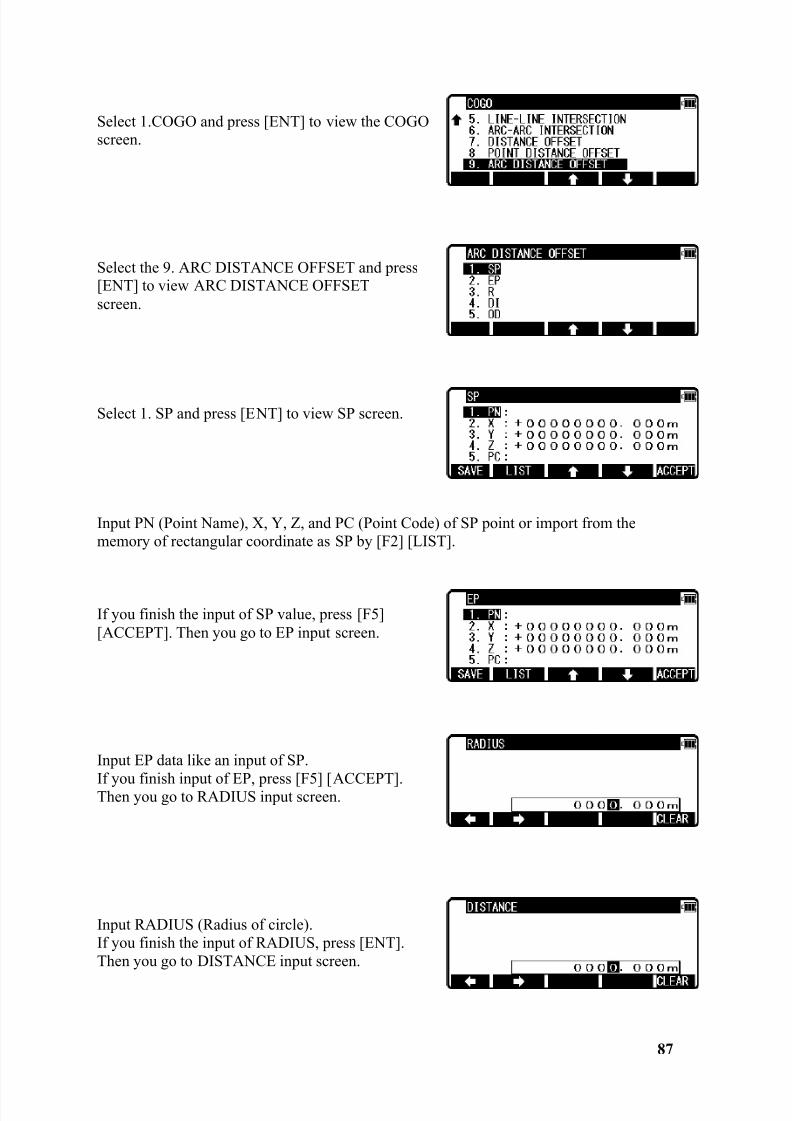
Select 1.COGO and press [ENT] to view the COGOscreen.
Select the 9. ARC DISTANCE OFFSET and press[ENT] to view ARC DISTANCE OFFSETscreen.
Select 1. SP and press [ENT] to view SP screen.
Input PN (Point Name), X, Y, Z, and PC (Point Code) of SP point or import from thememory of rectangular coordinate as SP by [F2] [LIST].
If you finish the input of SP value, press [F5][ACCEPT]. Then you go to EP input screen.
Input EP data like an input of SP.
If you finish input of EP, press [F5] [ACCEPT].Then you go to RADIUS input screen.
Input RADIUS (Radius of circle).If you finish the input of RADIUS, press [ENT].Then you go to DISTANCE input screen.
8/15/2019 r400v Man Ptl En
http://slidepdf.com/reader/full/r400v-man-ptl-en 89/142
8/15/2019 r400v Man Ptl En
http://slidepdf.com/reader/full/r400v-man-ptl-en 90/142
89
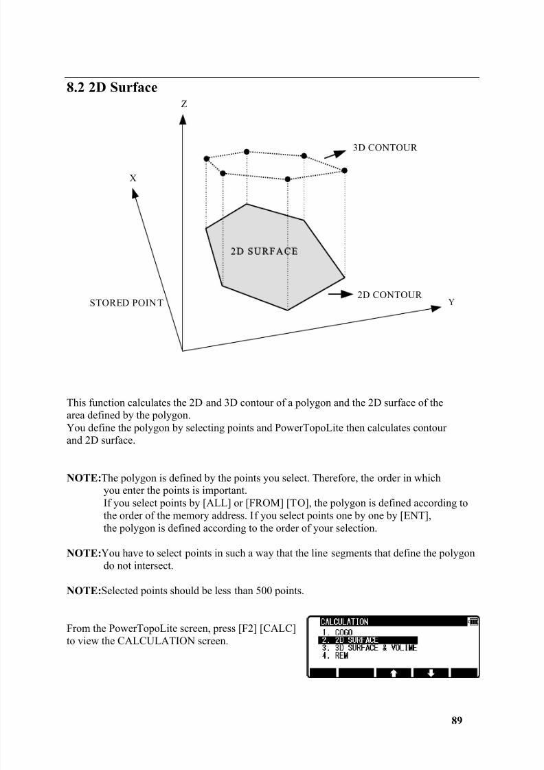
8.2 2D Surface
This function calculates the 2D and 3D contour of a polygon and the 2D surface of thearea defined by the polygon.You define the polygon by selecting points and PowerTopoLite then calculates contourand 2D surface.
NOTE: The polygon is defined by the points you select. Therefore, the order in whichyou enter the points is important.If you select points by [ALL] or [FROM] [TO], the polygon is defined according tothe order of the memory address. If you select points one by one by [ENT],the polygon is defined according to the order of your selection.
NOTE: You have to select points in such a way that the line segments that define the polygondo not intersect.
NOTE: Selected points should be less than 500 points.
From the PowerTopoLite screen, press [F2] [CALC]to view the CALCULATION screen.
X
2D CONTOUR
Z
Y
3D CONTOUR
2D SURFACE
STORED POINT
8/15/2019 r400v Man Ptl En
http://slidepdf.com/reader/full/r400v-man-ptl-en 91/142
90
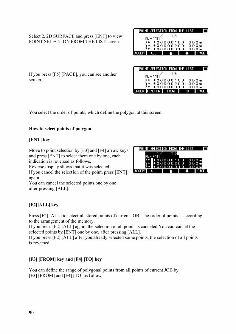
Select 2. 2D SURFACE and press [ENT] to viewPOINT SELECTION FROM THE LIST screen.
If you press [F5] [PAGE], you can see anotherscreen.
You select the order of points, which define the polygon at this screen.
How to select points of polygon
[ENT] key
Move to point selection by [F3] and [F4] arrow keysand press [ENT] to select them one by one, eachindication is reversed as follows.Reverse display shows that it was selected.If you cancel the selection of the point, press [ENT]again.You can cancel the selected points one by oneafter pressing [ALL].
[F2][ALL] key
Press [F2] [ALL] to select all stored points of current JOB. The order of points is accordingto the arrangement of the memory.If you press [F2] [ALL] again, the selection of all points is canceled.You can cancel the
selected points by [ENT] one by one, after pressing [ALL].If you press [F2] [ALL] after you already selected some points, the selection of all pointsis reversed.
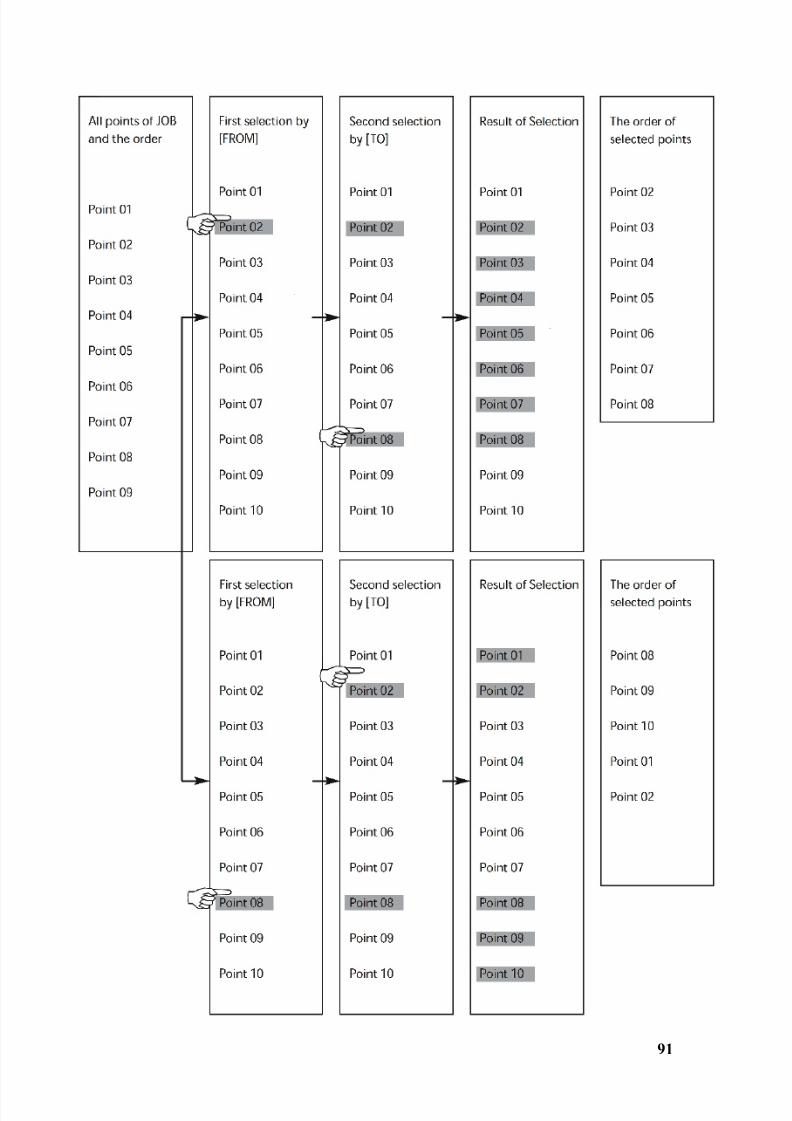
[F3] [FROM] key and [F4] [TO] key
You can define the range of polygonal points from all points of current JOB by[F3] [FROM] and [F4] [TO] as follows.
8/15/2019 r400v Man Ptl En
http://slidepdf.com/reader/full/r400v-man-ptl-en 92/142
91
8/15/2019 r400v Man Ptl En
http://slidepdf.com/reader/full/r400v-man-ptl-en 93/142
92
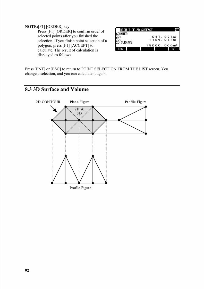
NOTE: [F1] [ORDER] keyPress [F1] [ORDER] to confirm order ofselected points after you finished theselection. If you finish point selection of a polygon, press [F1] [ACCEPT] to
calculate. The result of calculation isdisplayed as follows.
Press [ENT] or [ESC] to return to POINT SELECTION FROM THE LIST screen. Youchange a selection, and you can calculate it again.
8.3 3D Surface and Volume
2D-CON TOUR Plane Figure Profile Figure
Profile Figure
2D &3D
8/15/2019 r400v Man Ptl En
http://slidepdf.com/reader/full/r400v-man-ptl-en 94/142
93
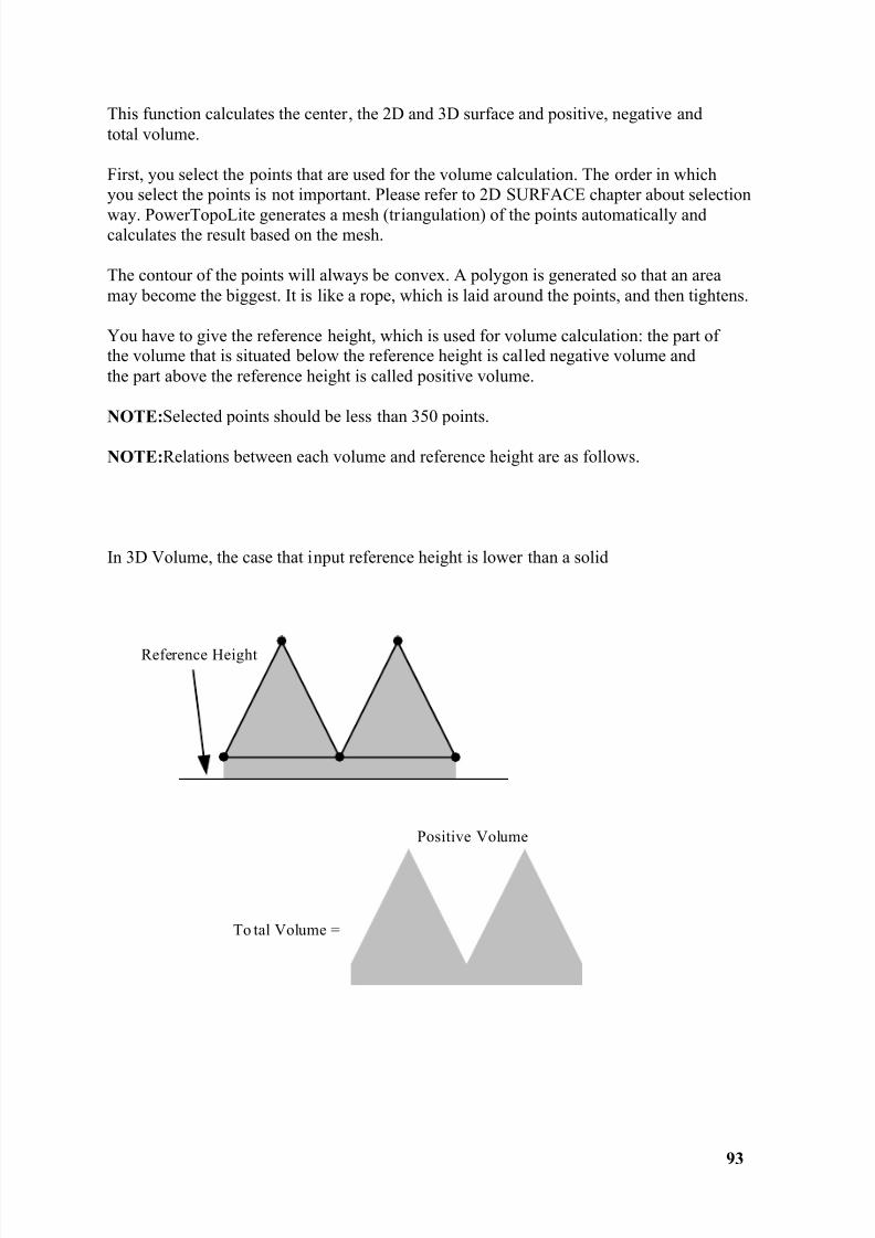
This function calculates the center, the 2D and 3D surface and positive, negative andtotal volume.
First, you select the points that are used for the volume calculation. The order in whichyou select the points is not important. Please refer to 2D SURFACE chapter about selection
way. PowerTopoLite generates a mesh (triangulation) of the points automatically andcalculates the result based on the mesh.
The contour of the points will always be convex. A polygon is generated so that an areamay become the biggest. It is like a rope, which is laid around the points, and then tightens.
You have to give the reference height, which is used for volume calculation: the part ofthe volume that is situated below the reference height is called negative volume andthe part above the reference height is called positive volume.
NOTE: Selected points should be less than 350 points.
NOTE: Relations between each volume and reference height are as follows.
In 3D Volume, the case that input reference height is lower than a solid
Reference Height
To tal Volume =
Positive Volume
8/15/2019 r400v Man Ptl En
http://slidepdf.com/reader/full/r400v-man-ptl-en 95/142
94
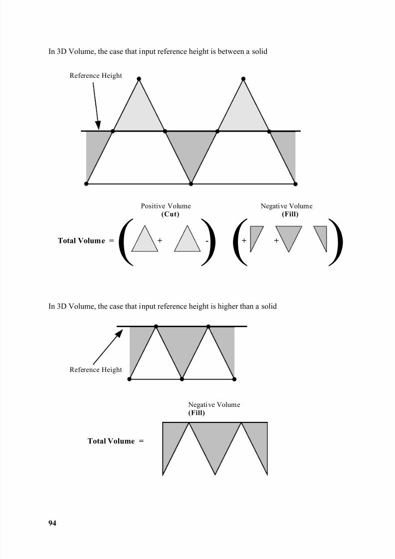
In 3D Volume, the case that input reference height is between a solid
In 3D Volume, the case that input reference height is higher than a solid
Reference Height
( ) ( )Total Volume = + - + +
Positive Volume(Cut)
Negative Volume(Fill)
Negative Volume(Fill)
Reference Height
Total Volume =
8/15/2019 r400v Man Ptl En
http://slidepdf.com/reader/full/r400v-man-ptl-en 96/142
95
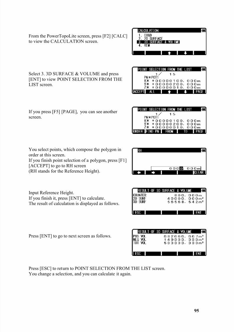
From the PowerTopoLite screen, press [F2] [CALC]to view the CALCULATION screen.
Select 3. 3D SURFACE & VOLUME and press[ENT] to view POINT SELECTION FROM THELIST screen.
If you press [F5] [PAGE], you can see anotherscreen.
You select points, which compose the polygon inorder at this screen.If you finish point selection of a polygon, press [F1][ACCEPT] to go to RH screen(RH stands for the Reference Height).
Input Reference Height.If you finish it, press [ENT] to calculate.The result of calculation is displayed as follows.
Press [ENT] to go to next screen as follows.
Press [ESC] to return to POINT SELECTION FROM THE LIST screen.You change a selection, and you can calculate it again.
8/15/2019 r400v Man Ptl En
http://slidepdf.com/reader/full/r400v-man-ptl-en 97/142
96
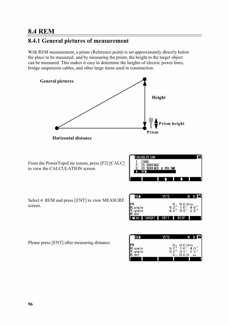
8.4 REM8.4.1 General pictures of measurement
With REM measurement, a prism (Reference point) is set approximately directly belowthe place to be measured, and by measuring the prism, the height to the target objectcan be measured. This makes it easy to determine the heights of electric power lines, bridge suspension cables, and other large items used in construction.
From the PowerTopoLite screen, press [F2] [CALC]
to view the CALCULATION screen.
Select 4. REM and press [ENT] to view MEASUREscreen.
Please press [ENT] after measuring distance.
General pictures
Horizontal distance
Height
Prism height
Prism
8/15/2019 r400v Man Ptl En
http://slidepdf.com/reader/full/r400v-man-ptl-en 98/142
97
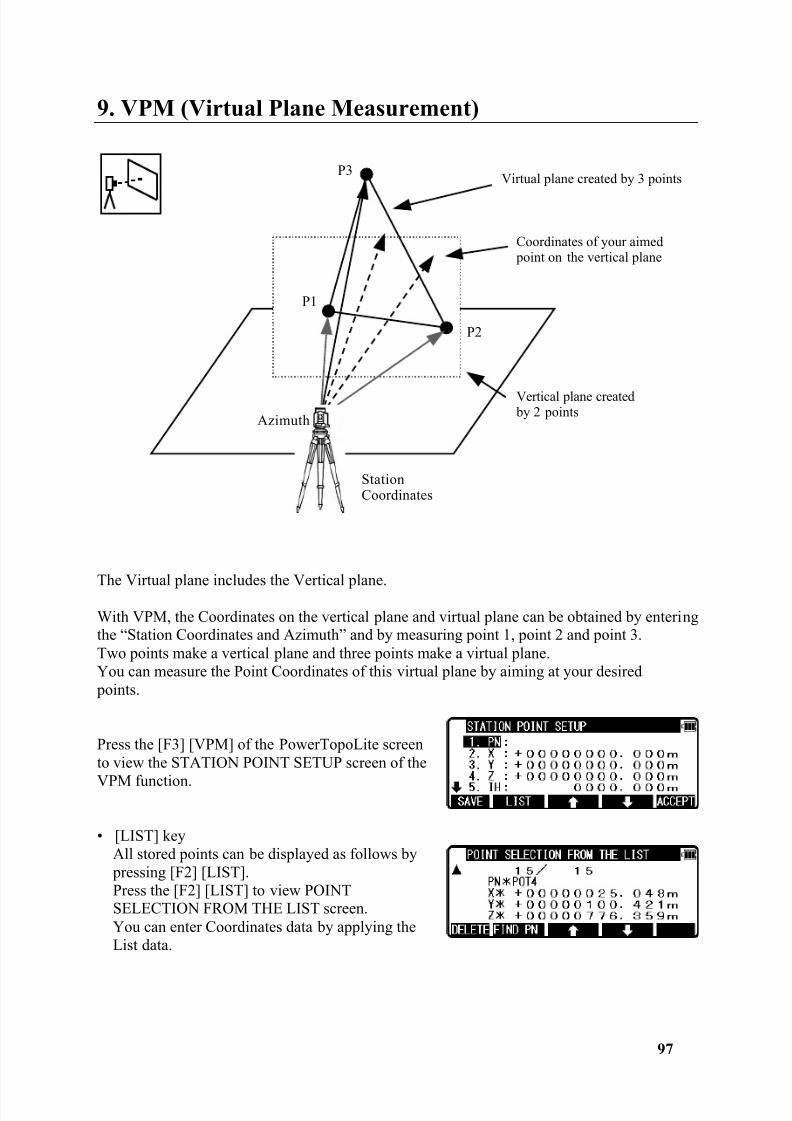
9. VPM (Virtual Plane Measurement)
The Virtual plane includes the Vertical plane.
With VPM, the Coordinates on the vertical plane and virtual plane can be obtained by enteringthe “Station Coordinates and Azimuth” and by measuring point 1, point 2 and point 3.Two points make a vertical plane and three points make a virtual plane.You can measure the Point Coordinates of this virtual plane by aiming at your desired points.
Press the [F3] [VPM] of the PowerTopoLite screento view the STATION POINT SETUP screen of the
VPM function.
• [LIST] keyAll stored points can be displayed as follows by pressing [F2] [LIST].Press the [F2] [LIST] to view POINTSELECTION FROM THE LIST screen.You can enter Coordinates data by applying theList data.
P1
P2
P3
Azimuth
StationCoordinates
Vertical plane created by 2 points
Coordinates of your aimed point on the vertical plane
Virtual plane created by 3 points
8/15/2019 r400v Man Ptl En
http://slidepdf.com/reader/full/r400v-man-ptl-en 99/142
98
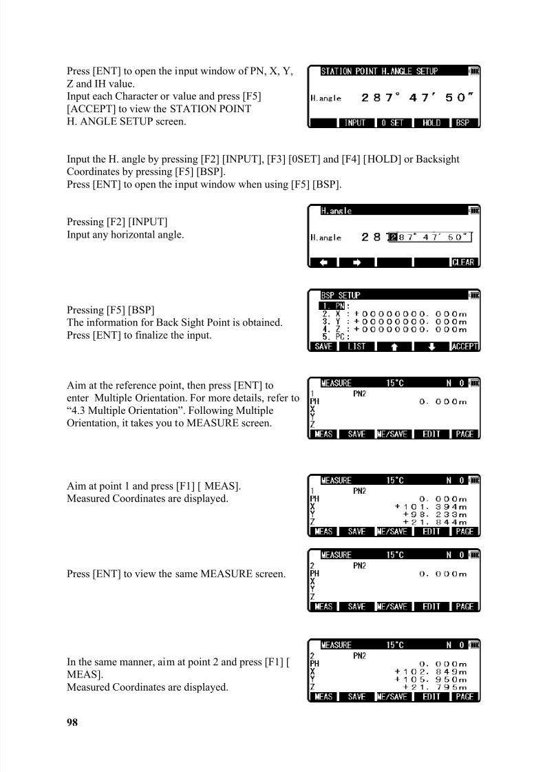
Press [ENT] to open the input window of PN, X, Y,Z and IH value.Input each Character or value and press [F5][ACCEPT] to view the STATION POINTH. ANGLE SETUP screen.
Input the H. angle by pressing [F2] [INPUT], [F3] [0SET] and [F4] [HOLD] or BacksightCoordinates by pressing [F5] [BSP].Press [ENT] to open the input window when using [F5] [BSP].
Pressing [F2] [INPUT]Input any horizontal angle.
Pressing [F5] [BSP]The information for Back Sight Point is obtained.Press [ENT] to finalize the input.
Aim at the reference point, then press [ENT] to enter Multiple Orientation. For more details, refer to“4.3 Multiple Orientation”. Following MultipleOrientation, it takes you to MEASURE screen.
Aim at point 1 and press [F1] [ MEAS].Measured Coordinates are displayed.
Press [ENT] to view the same MEASURE screen.
In the same manner, aim at point 2 and press [F1] [
MEAS].Measured Coordinates are displayed.
8/15/2019 r400v Man Ptl En
http://slidepdf.com/reader/full/r400v-man-ptl-en 100/142
99
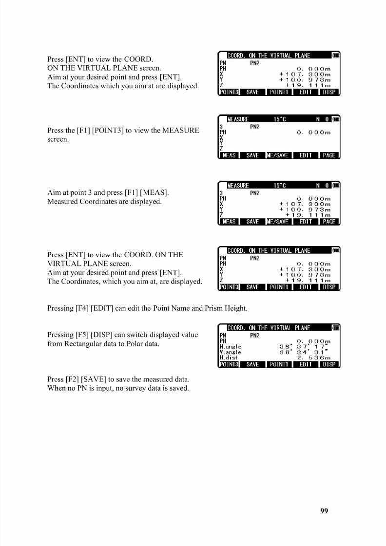
Press [ENT] to view the COORD.ON THE VIRTUAL PLANE screen.Aim at your desired point and press [ENT].The Coordinates which you aim at are displayed.
Press the [F1] [POINT3] to view the MEASUREscreen.
Aim at point 3 and press [F1] [MEAS].Measured Coordinates are displayed.
Press [ENT] to view the COORD. ON THEVIRTUAL PLANE screen.Aim at your desired point and press [ENT].The Coordinates, which you aim at, are displayed.
Pressing [F4] [EDIT] can edit the Point Name and Prism Height.
Pressing [F5] [DISP] can switch displayed valuefrom Rectangular data to Polar data.
Press [F2] [SAVE] to save the measured data.When no PN is input, no survey data is saved.
8/15/2019 r400v Man Ptl En
http://slidepdf.com/reader/full/r400v-man-ptl-en 101/142
100
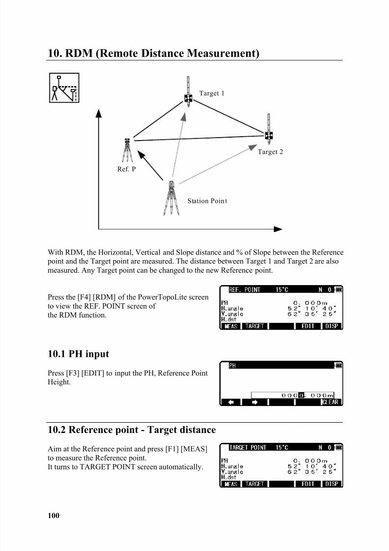
10. RDM (Remote Distance Measurement)
With RDM, the Horizontal, Vertical and Slope distance and % of Slope between the Reference point and the Target point are measured. The distance between Target 1 and Target 2 are alsomeasured. Any Target point can be changed to the new Reference point.
Press the [F4] [RDM] of the PowerTopoLite screento view the REF. POINT screen ofthe RDM function.
10.1 PH input
Press [F3] [EDIT] to input the PH, Reference PointHeight.
10.2 Reference point - Target distance
Aim at the Reference point and press [F1] [MEAS]to measure the Reference point.It turns to TARGET POINT screen automatically.
Target 1
Target 2
Ref. P
Station Poin t
8/15/2019 r400v Man Ptl En
http://slidepdf.com/reader/full/r400v-man-ptl-en 102/142
8/15/2019 r400v Man Ptl En
http://slidepdf.com/reader/full/r400v-man-ptl-en 103/142
102
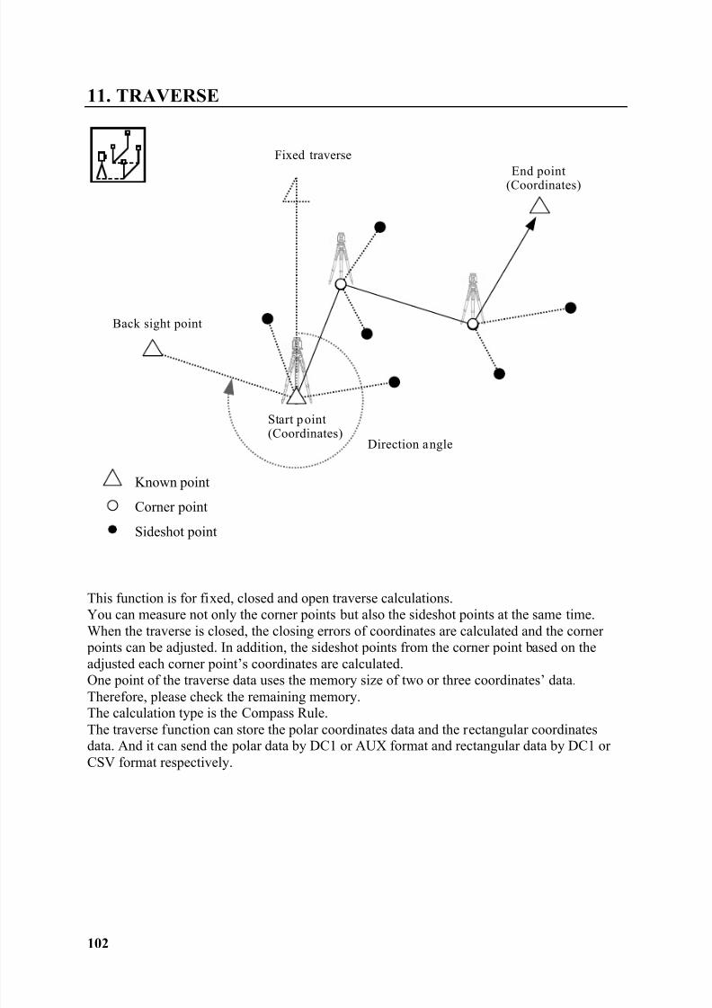
11. TRAVERSE
This function is for fixed, closed and open traverse calculations.You can measure not only the corner points but also the sideshot points at the same time.When the traverse is closed, the closing errors of coordinates are calculated and the corner points can be adjusted. In addition, the sideshot points from the corner point based on theadjusted each corner point’s coordinates are calculated.One point of the traverse data uses the memory size of two or three coordinates’ data.Therefore, please check the remaining memory.The calculation type is the Compass Rule.The traverse function can store the polar coordinates data and the rectangular coordinatesdata. And it can send the polar data by DC1 or AUX format and rectangular data by DC1 orCSV format respectively.
Fixed traverse
Start p oint(Coordinates)
End point(Coordinates)
Direction angle
Back sight point
Sideshot point
Corner point
Known point
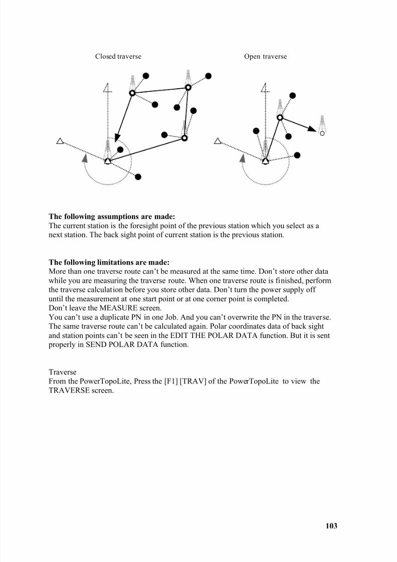
8/15/2019 r400v Man Ptl En
http://slidepdf.com/reader/full/r400v-man-ptl-en 104/142
103
The following assumptions are made:The current station is the foresight point of the previous station which you select as anext station. The back sight point of current station is the previous station.
The following limitations are made:More than one traverse route can’t be measured at the same time. Don’t store other datawhile you are measuring the traverse route. When one traverse route is finished, performthe traverse calculation before you store other data. Don’t turn the power supply offuntil the measurement at one start point or at one corner point is completed.Don’t leave the MEASURE screen.You can’t use a duplicate PN in one Job. And you can’t overwrite the PN in the traverse.The same traverse route can’t be calculated again. Polar coordinates data of back sightand station points can’t be seen in the EDIT THE POLAR DATA function. But it is sent properly in SEND POLAR DATA function.
TraverseFrom the PowerTopoLite, Press the [F1] [TRAV] of the PowerTopoLite to view the
TRAVERSE screen.
Closed traverse Open traverse
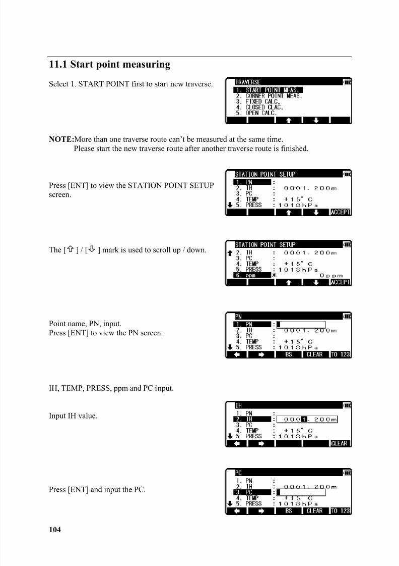
8/15/2019 r400v Man Ptl En
http://slidepdf.com/reader/full/r400v-man-ptl-en 105/142
104
11.1 Start point measuring
Select 1. START POINT first to start new traverse.
NOTE: More than one traverse route can’t be measured at the same time.Please start the new traverse route after another traverse route is finished.
Press [ENT] to view the STATION POINT SETUP
screen.
The [ ] / [ ] mark is used to scroll up / down.
Point name, PN, input.Press [ENT] to view the PN screen.
IH, TEMP, PRESS, ppm and PC input.
Input IH value.
Press [ENT] and input the PC.
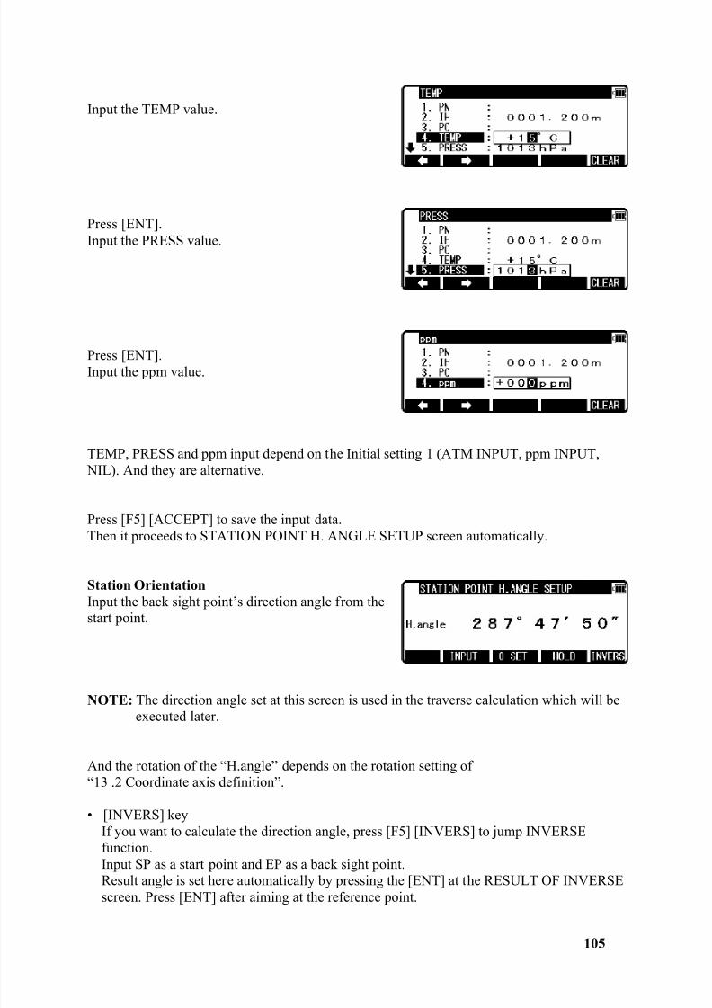
8/15/2019 r400v Man Ptl En
http://slidepdf.com/reader/full/r400v-man-ptl-en 106/142
105
Input the TEMP value.
Press [ENT].Input the PRESS value.
Press [ENT].Input the ppm value.
TEMP, PRESS and ppm input depend on the Initial setting 1 (ATM INPUT, ppm INPUT, NIL). And they are alternative.
Press [F5] [ACCEPT] to save the input data.Then it proceeds to STATION POINT H. ANGLE SETUP screen automatically.
Station OrientationInput the back sight point’s direction angle from thestart point.
NOTE: The direction angle set at this screen is used in the traverse calculation which will beexecuted later.
And the rotation of the “H.angle” depends on the rotation setting of“13 .2 Coordinate axis definition”.
• [INVERS] keyIf you want to calculate the direction angle, press [F5] [INVERS] to jump INVERSEfunction.Input SP as a start point and EP as a back sight point.
Result angle is set here automatically by pressing the [ENT] at the RESULT OF INVERSEscreen. Press [ENT] after aiming at the reference point.
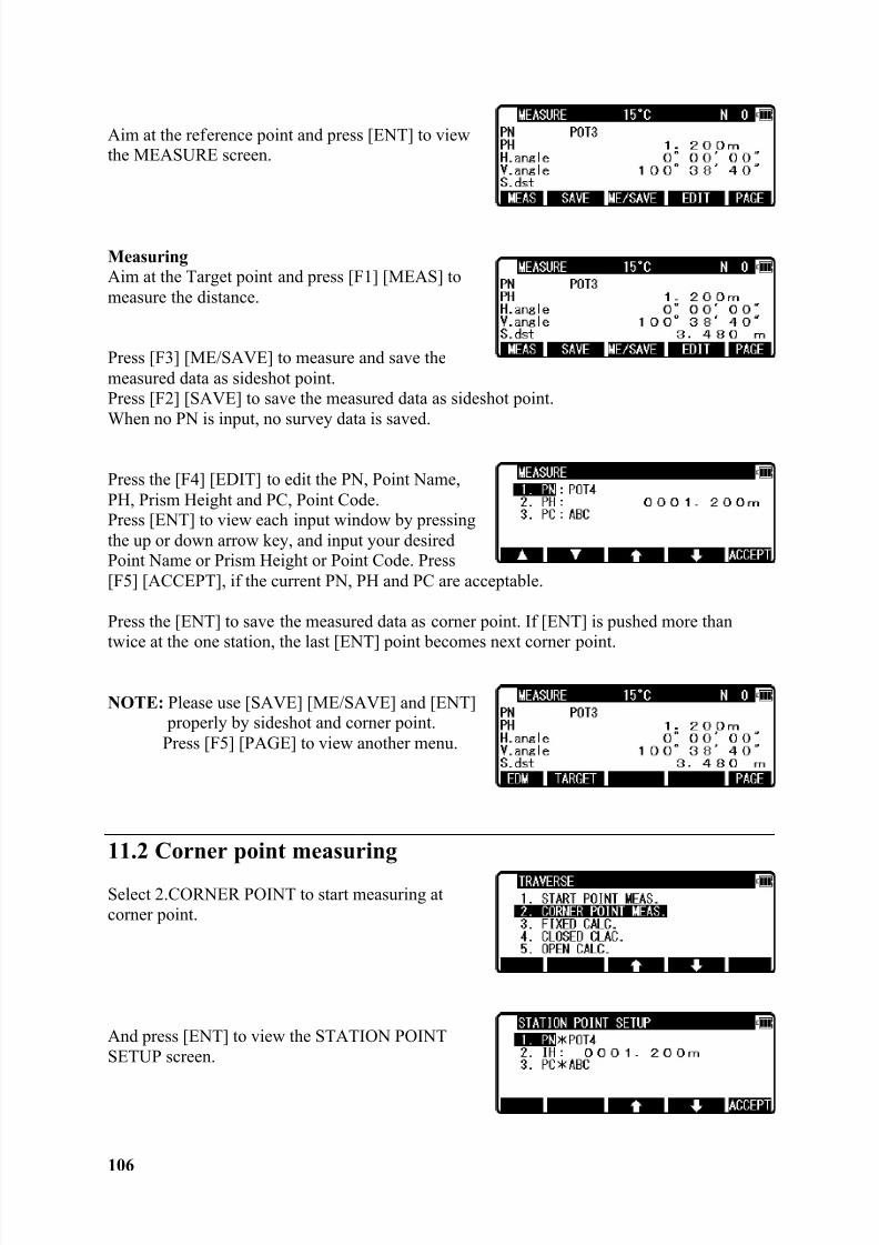
8/15/2019 r400v Man Ptl En
http://slidepdf.com/reader/full/r400v-man-ptl-en 107/142
106
Aim at the reference point and press [ENT] to viewthe MEASURE screen.
MeasuringAim at the Target point and press [F1] [MEAS] tomeasure the distance.
Press [F3] [ME/SAVE] to measure and save themeasured data as sideshot point.Press [F2] [SAVE] to save the measured data as sideshot point.When no PN is input, no survey data is saved.
Press the [F4] [EDIT] to edit the PN, Point Name,PH, Prism Height and PC, Point Code.Press [ENT] to view each input window by pressingthe up or down arrow key, and input your desiredPoint Name or Prism Height or Point Code. Press[F5] [ACCEPT], if the current PN, PH and PC are acceptable.
Press the [ENT] to save the measured data as corner point. If [ENT] is pushed more thantwice at the one station, the last [ENT] point becomes next corner point.
NOTE: Please use [SAVE] [ME/SAVE] and [ENT] properly by sideshot and corner point.
Press [F5] [PAGE] to view another menu.
11.2 Corner point measuring
Select 2.CORNER POINT to start measuring atcorner point.
And press [ENT] to view the STATION POINTSETUP screen.
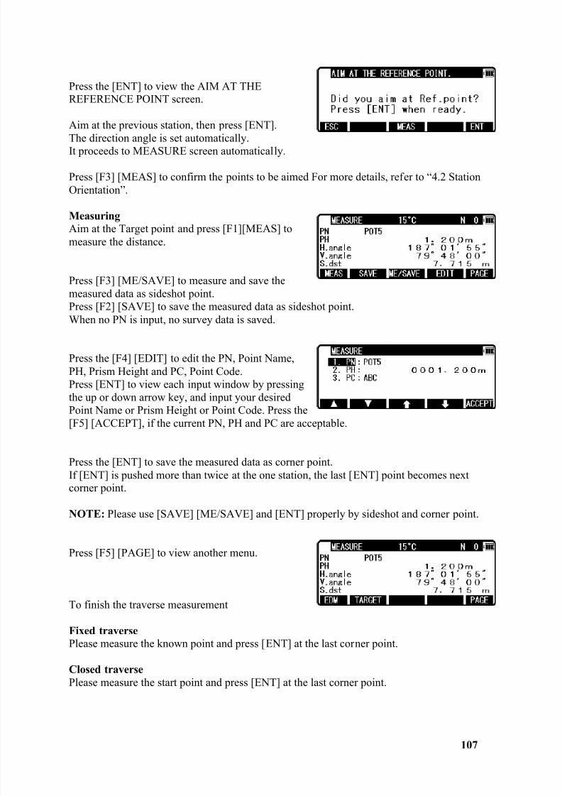
8/15/2019 r400v Man Ptl En
http://slidepdf.com/reader/full/r400v-man-ptl-en 108/142
107
Press the [ENT] to view the AIM AT THEREFERENCE POINT screen.
Aim at the previous station, then press [ENT].
The direction angle is set automatically.It proceeds to MEASURE screen automatically.
Press [F3] [MEAS] to confirm the points to be aimed For more details, refer to “4.2 StationOrientation”.
MeasuringAim at the Target point and press [F1][MEAS] tomeasure the distance.
Press [F3] [ME/SAVE] to measure and save themeasured data as sideshot point.Press [F2] [SAVE] to save the measured data as sideshot point.When no PN is input, no survey data is saved.
Press the [F4] [EDIT] to edit the PN, Point Name,PH, Prism Height and PC, Point Code.Press [ENT] to view each input window by pressingthe up or down arrow key, and input your desiredPoint Name or Prism Height or Point Code. Press the[F5] [ACCEPT], if the current PN, PH and PC are acceptable.
Press the [ENT] to save the measured data as corner point.If [ENT] is pushed more than twice at the one station, the last [ENT] point becomes nextcorner point.
NOTE: Please use [SAVE] [ME/SAVE] and [ENT] properly by sideshot and corner point.
Press [F5] [PAGE] to view another menu.
To finish the traverse measurement
Fixed traversePlease measure the known point and press [ENT] at the last corner point.
Closed traversePlease measure the start point and press [ENT] at the last corner point.
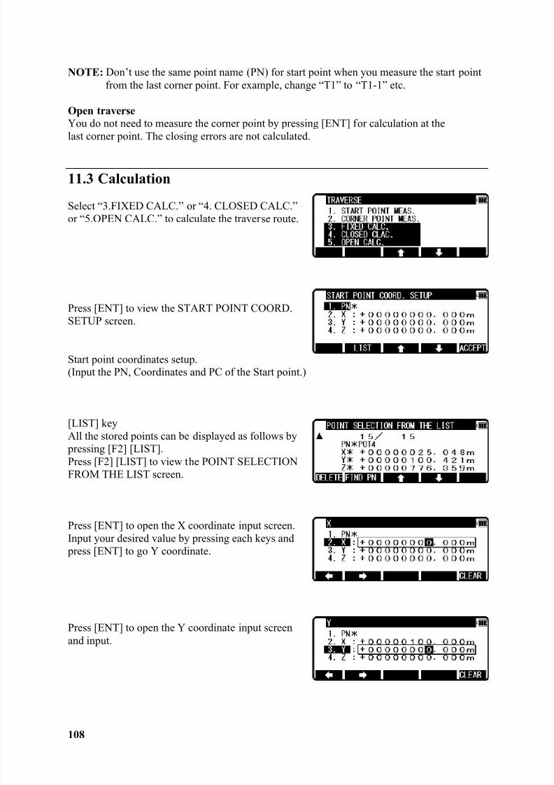
8/15/2019 r400v Man Ptl En
http://slidepdf.com/reader/full/r400v-man-ptl-en 109/142
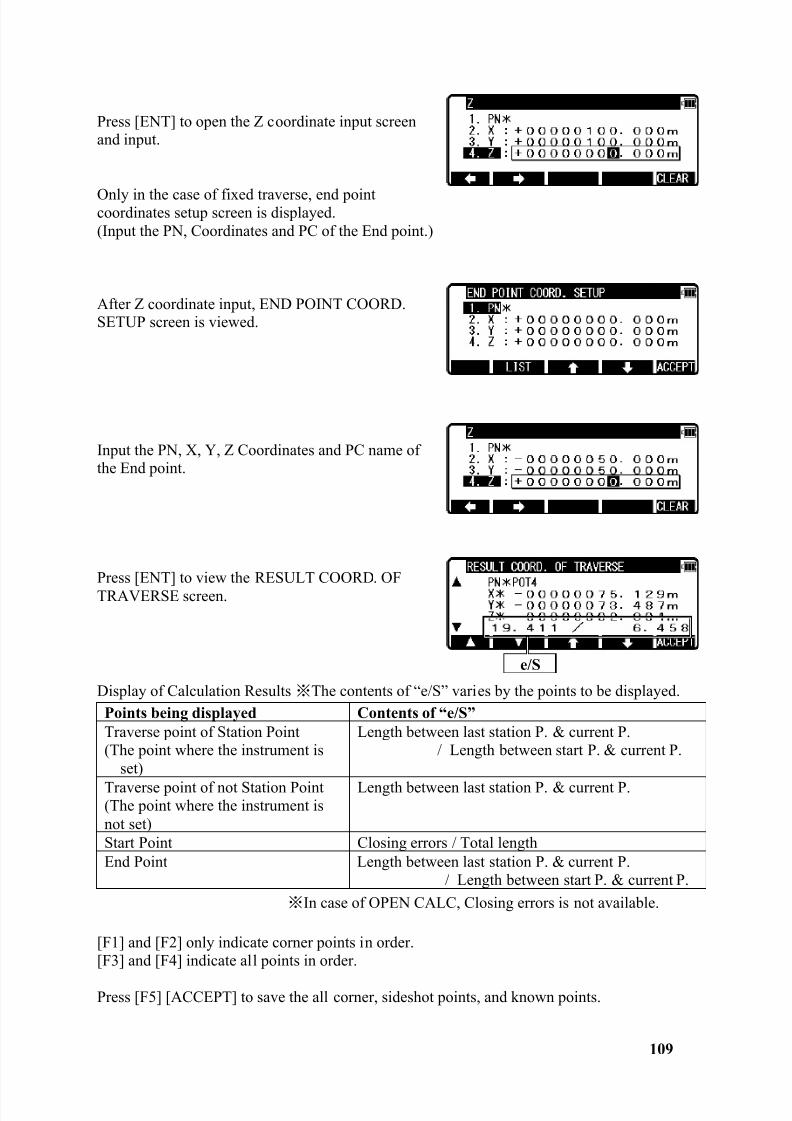
8/15/2019 r400v Man Ptl En
http://slidepdf.com/reader/full/r400v-man-ptl-en 110/142
109
Press [ENT] to open the Z coordinate input screenand input.
Only in the case of fixed traverse, end pointcoordinates setup screen is displayed.(Input the PN, Coordinates and PC of the End point.)
After Z coordinate input, END POINT COORD.SETUP screen is viewed.
Input the PN, X, Y, Z Coordinates and PC name ofthe End point.
Press [ENT] to view the RESULT COORD. OFTRAVERSE screen.
Display of Calculation Results The contents of “e/S” varies by the points to be displayed.Points being displayed Contents of “e/S”Traverse point of Station Point(The point where the instrument is
set)
Length between last station P. & current P./ Length between start P. & current P.
Traverse point of not Station Point(The point where the instrument isnot set)
Length between last station P. & current P.
Start Point Closing errors / Total lengthEnd Point Length between last station P. & current P.
/ Length between start P. & current P.In case of OPEN CALC, Closing errors is not available.
[F1] and [F2] only indicate corner points in order.[F3] and [F4] indicate all points in order.
Press [F5] [ACCEPT] to save the all corner, sideshot points, and known points.
e/S
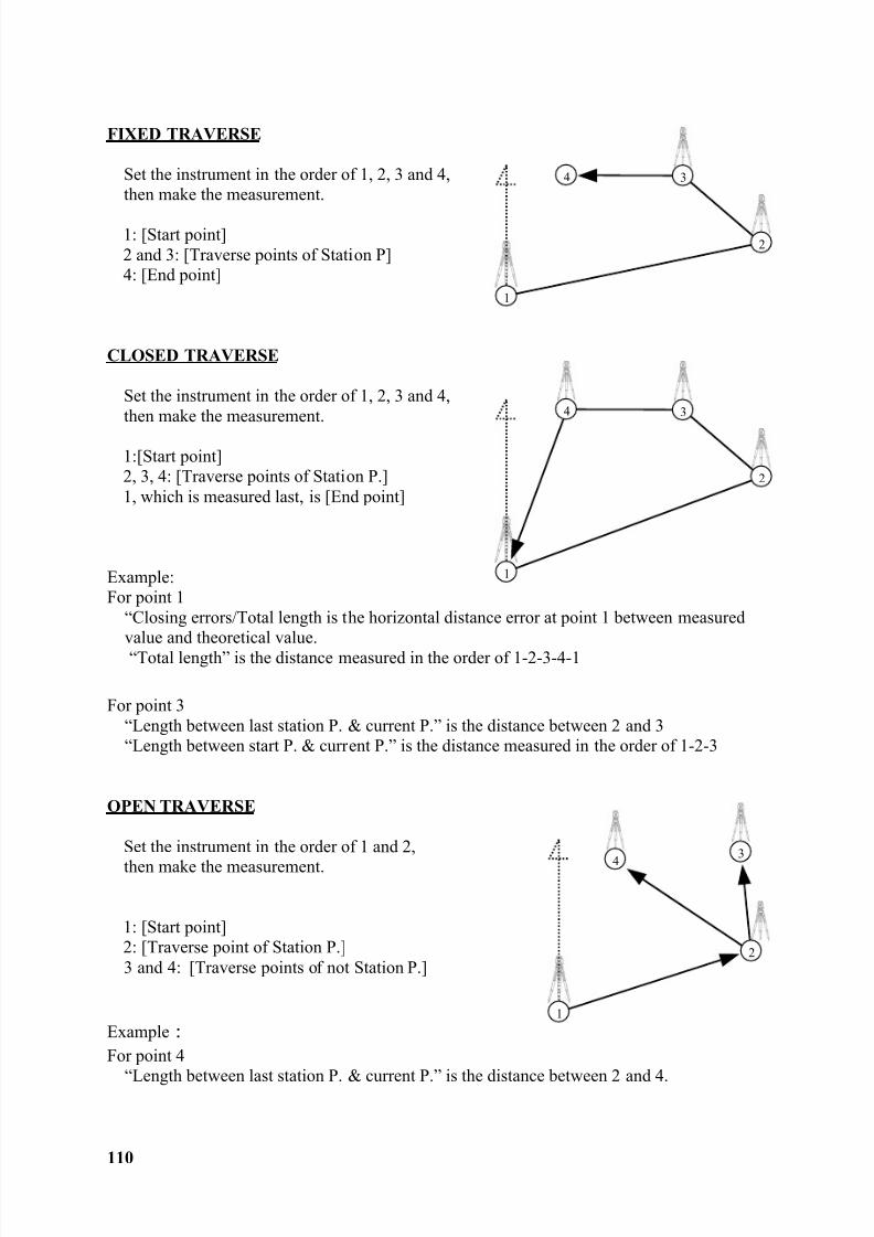
8/15/2019 r400v Man Ptl En
http://slidepdf.com/reader/full/r400v-man-ptl-en 111/142
8/15/2019 r400v Man Ptl En
http://slidepdf.com/reader/full/r400v-man-ptl-en 112/142
111
12. INPUT / OUTPUT
The communication setting and the Input/Output of data are performed by thisfunction.We recommend you not to press any key until data transfer is completed whiletransfer operation.
Notice concerning the unit of data to transfer.
Output data (Rect. data & Polar data).Coordinates and Distance data.
The unit is output by “m” unit even if the distance unit setting of the instrument tosend the data is “m”, “ft” and “ft+inch”.
Angle, Temperature and Pressure data.The data is output according to the unit setting of the Angle, Temperature and
Pressure of the instrument to send the data.Input data (Rect. data).Coordinates data.
The Coordinates data received is input in the instrument as data of “m” unit.Then, it is converted according to the distance unit which is set in the instrument,and displayed on the screen.
Data format1. DC-1
[In case of Text File read / write ]
Record No. : Site name : L/F codeRecord No. : P. Name : X Coord. : Y Coord. : Z Coord. L/F code
[In case of Communication with COM ]Record No. : Site name : BCC : L/F code
Record No. : P. Name : X Coord. : Y Coord. : Z Coord. : BCC L/F code
[Record No.]The Record number is a 5-digit serial number.(the number consists of a 4-digit serial number plus one digit.The last digit represents the data type. 1: Site name; 2: Survey P.data)
[P. Name] The Survey P. number is handled as text data, if it is input.
[ : ] “ : ” is used to separate items.
[Coordinate data] X, Y, and Z coordinate dataA 6-digit integer part and a 3-digit fraction part represent coordinate data.
[BCC]
To detect a data transmission error, BCC is calculated per block and attached tothe end of data.
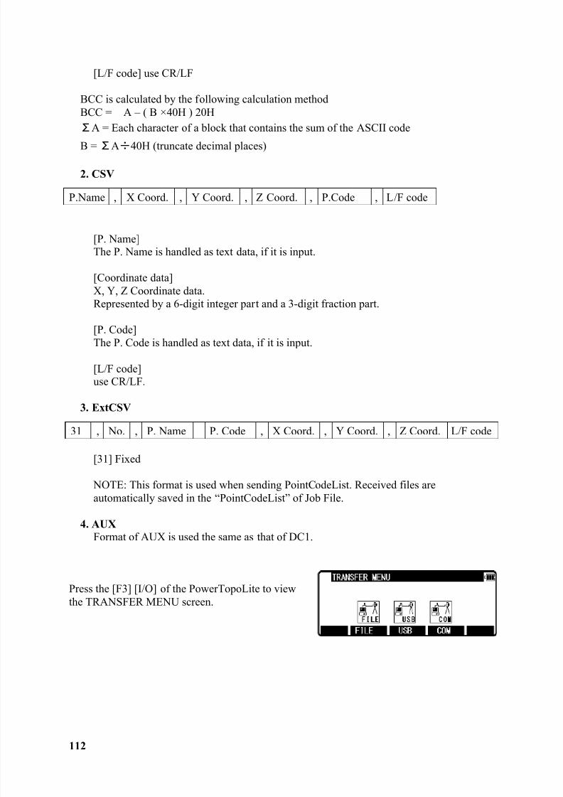
8/15/2019 r400v Man Ptl En
http://slidepdf.com/reader/full/r400v-man-ptl-en 113/142
112
[L/F code] use CR/LF
BCC is calculated by the following calculation methodBCC = A – ( B ! 40H ) 20H
A = Each character of a block that contains the sum of the ASCII code
B = A 40H (truncate decimal places)
2. CSV
[P. Name]The P. Name is handled as text data, if it is input.
[Coordinate data]X, Y, Z Coordinate data.Represented by a 6-digit integer part and a 3-digit fraction part.
[P. Code]The P. Code is handled as text data, if it is input.
[L/F code]use CR/LF.
3. ExtCSV
[31] Fixed
NOTE: This format is used when sending PointCodeList. Received files areautomatically saved in the “PointCodeList” of Job File.
4. AUXFormat of AUX is used the same as that of DC1.
Press the [F3] [I/O] of the PowerTopoLite to viewthe TRANSFER MENU screen.
P.Name , X Coord. , Y Coord. , Z Coord. , P.Code , L/F code
31 , No. , P. Name P. Code , X Coord. , Y Coord. , Z Coord. L/F code
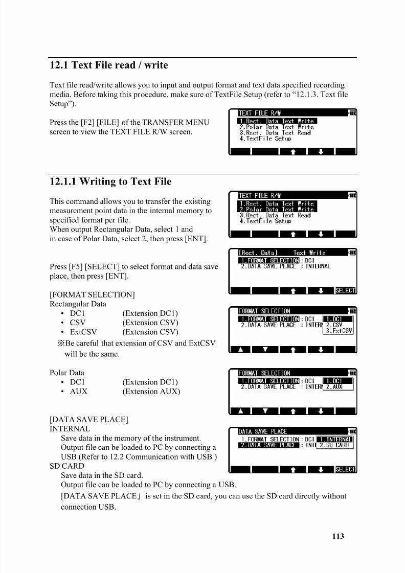
8/15/2019 r400v Man Ptl En
http://slidepdf.com/reader/full/r400v-man-ptl-en 114/142
113
12.1 Text File read / write
Text file read/write allows you to input and output format and text data specified recordingmedia. Before taking this procedure, make sure of TextFile Setup (refer to “12.1.3. Text fileSetup”).
Press the [F2] [FILE] of the TRANSFER MENUscreen to view the TEXT FILE R/W screen.
12.1.1 Writing to Text File
This command allows you to transfer the existingmeasurement point data in the internal memory tospecified format per file.When output Rectangular Data, select 1 andin case of Polar Data, select 2, then press [ENT].
Press [F5] [SELECT] to select format and data save place, then press [ENT].
[FORMAT SELECTION]Rectangular Data
• DC1 (Extension DC1)• CSV (Extension CSV)• ExtCSV (Extension CSV)
Be careful that extension of CSV and ExtCSVwill be the same.
Polar Data• DC1 (Extension DC1)• AUX (Extension AUX)
[DATA SAVE PLACE]INTERNAL
Save data in the memory of the instrument.Output file can be loaded to PC by connecting aUSB (Refer to 12.2 Communication with USB )
SD CARDSave data in the SD card.Output file can be loaded to PC by connecting a USB.[DATA SAVE PLACE is set in the SD card, you can use the SD card directly withoutconnection USB.
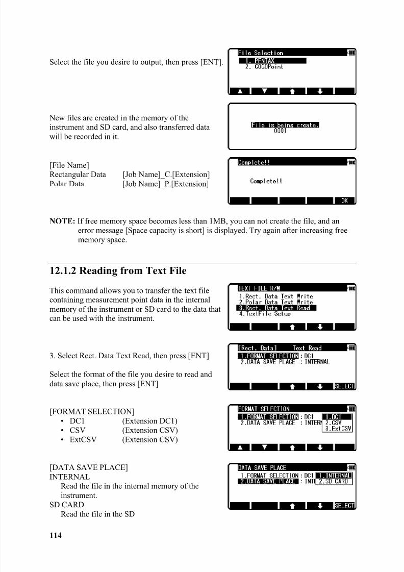
8/15/2019 r400v Man Ptl En
http://slidepdf.com/reader/full/r400v-man-ptl-en 115/142
114
Select the file you desire to output, then press [ENT].
New files are created in the memory of theinstrument and SD card, and also transferred datawill be recorded in it.
[File Name]Rectangular Data [Job Name]_C.[Extension]Polar Data [Job Name]_P.[Extension]
NOTE: If free memory space becomes less than 1MB, you can not create the file, and anerror message [Space capacity is short] is displayed. Try again after increasing freememory space.
12.1.2 Reading from Text File
This command allows you to transfer the text file
containing measurement point data in the internalmemory of the instrument or SD card to the data thatcan be used with the instrument.
3. Select Rect. Data Text Read, then press [ENT]
Select the format of the file you desire to read anddata save place, then press [ENT]
[FORMAT SELECTION]• DC1 (Extension DC1)• CSV (Extension CSV)• ExtCSV (Extension CSV)
[DATA SAVE PLACE]INTERNAL
Read the file in the internal memory of theinstrument.
SD CARDRead the file in the SD
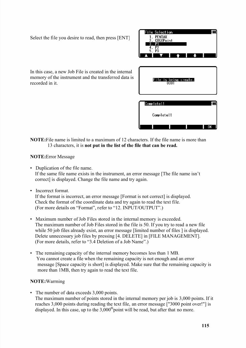
8/15/2019 r400v Man Ptl En
http://slidepdf.com/reader/full/r400v-man-ptl-en 116/142
115
Select the file you desire to read, then press [ENT]
In this case, a new Job File is created in the internalmemory of the instrument and the transferred data isrecorded in it.
NOTE: File name is limited to a maximum of 12 characters. If the file name is more than13 characters, it is not put in the list of the file that can be read.
NOTE: Error Message
• Duplication of the file name.If the same file name exists in the instrument, an error message [The file name isn’tcorrect] is displayed. Change the file name and try again.
• Incorrect format.If the format is incorrect, an error message [Format is not correct] is displayed.Check the format of the coordinate data and try again to read the text file.(For more details on “Format”, refer to “12. INPUT/OUTPUT”.)
• Maximum number of Job Files stored in the internal memory is exceeded.The maximum number of Job Files stored in the file is 50. If you try to read a new filewhile 50 job files already exist, an error message [limited number of files ] is displayed.Delete unnecessary job files by pressing [4. DELETE] in [FILE MANAGEMENT].
(For more details, refer to “3.4 Deletion of a Job Name”.)
• The remaining capacity of the internal memory becomes less than 1 MB.You cannot create a file when the remaining capacity is not enough and an errormessage [Space capacity is short] is displayed. Make sure that the remaining capacity ismore than 1MB, then try again to read the text file.
NOTE: Warrning
• The number of data exceeds 3,000 points.The maximum number of points stored in the internal memory per job is 3,000 points. If it
reaches 3,000 points during reading the text file, an error message ["3000 point over!"] isdisplayed. In this case, up to the 3,000 th point will be read, but after that no more.
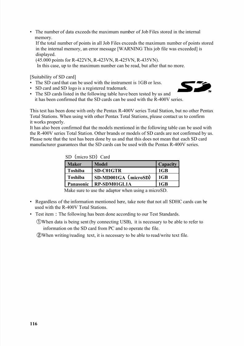
8/15/2019 r400v Man Ptl En
http://slidepdf.com/reader/full/r400v-man-ptl-en 117/142
116
• The number of data exceeds the maximum number of Job Files stored in the internalmemory.If the total number of points in all Job Files exceeds the maximum number of points storedin the internal memory, an error message [WARNING This job file was exceeded] isdisplayed.
(45.000 points for R-422VN, R-423VN, R-425VN, R-435VN).In this case, up to the maximum number can be read, but after that no more.
[Suitability of SD card]• The SD card that can be used with the instrument is 1GB or less.• SD card and SD logo is a registered trademark.• The SD cards listed in the following table have been tested by us and
it has been confirmed that the SD cards can be used with the R-400V series.
This test has been done with only the Pentax R-400V series Total Station, but no other PentaxTotal Stations. When using with other Pentax Total Stations, please contact us to confirmit works properly.It has also been confirmed that the models mentioned in the following table can be used withthe R-400V series Total Station. Other brands or models of SD cards are not confirmed by us.Please note that the test has been done by us and that this does not mean that each SD cardmanufacturer guarantees that the SD cards can be used with the Pentax R-400V series.
SD micro SD Card
Maker Model CapacityToshiba SD-C01GTR 1GBToshiba SD-MD001GA microSD 1GBPanasonic RP-SDM01GL1A 1GB
Make sure to use the adaptor when using a microSD.
• Regardless of the information mentioned here, take note that not all SDHC cards can beused with the R-400V Total Stations.
• Test item The following has been done according to our Test Standards.
When data is being sent (by connecting USB), it is necessary to be able to refer toinformation on the SD card from PC and to operate the file.
When writing/reading text, it is necessary to be able to read/write text file.
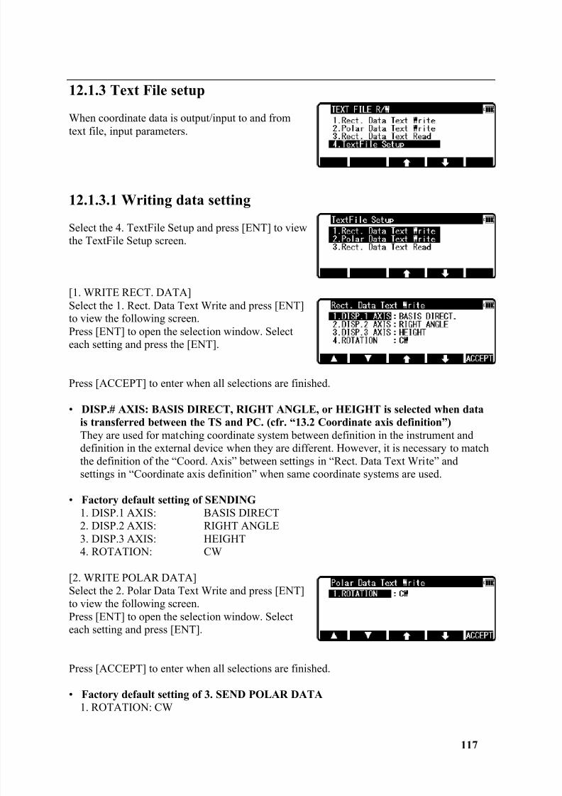
8/15/2019 r400v Man Ptl En
http://slidepdf.com/reader/full/r400v-man-ptl-en 118/142
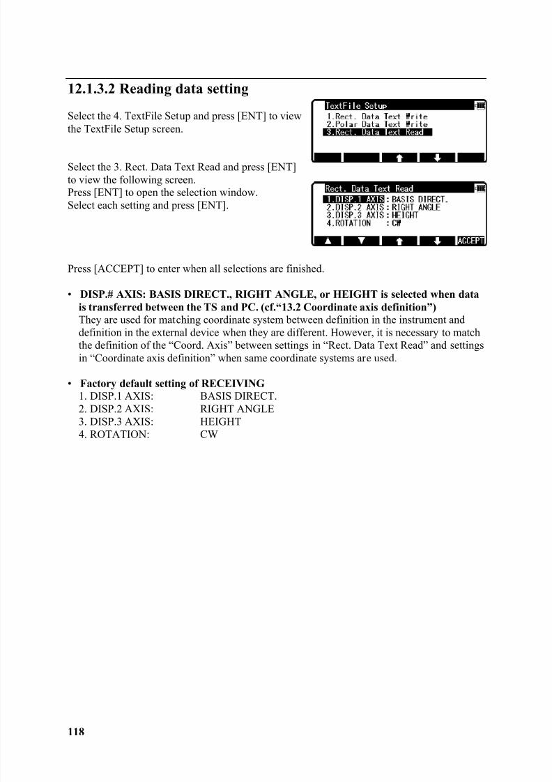
8/15/2019 r400v Man Ptl En
http://slidepdf.com/reader/full/r400v-man-ptl-en 119/142
118
12.1.3.2 Reading data setting
Select the 4. TextFile Setup and press [ENT] to viewthe TextFile Setup screen.
Select the 3. Rect. Data Text Read and press [ENT]to view the following screen.Press [ENT] to open the selection window.Select each setting and press [ENT].
Press [ACCEPT] to enter when all selections are finished.• DISP.# AXIS: BASIS DIRECT., RIGHT ANGLE, or HEIGHT is selected when data
is transferred between the TS and PC. (cf.“13.2 Coordinate axis definition”) They are used for matching coordinate system between definition in the instrument anddefinition in the external device when they are different. However, it is necessary to matchthe definition of the “Coord. Axis” between settings in “Rect. Data Text Read” and settingsin “Coordinate axis definition” when same coordinate systems are used.
• Factory default setting of RECEIVING1. DISP.1 AXIS: BASIS DIRECT.
2. DISP.2 AXIS: RIGHT ANGLE3. DISP.3 AXIS: HEIGHT4. ROTATION: CW
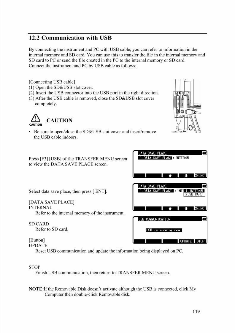
8/15/2019 r400v Man Ptl En
http://slidepdf.com/reader/full/r400v-man-ptl-en 120/142
119
12.2 Communication with USB
By connecting the instrument and PC with USB cable, you can refer to information in theinternal memory and SD card. You can use this to transfer the file in the internal memory andSD card to PC or send the file created in the PC to the internal memory or SD card.Connect the instrument and PC by USB cable as follows;
[Connecting USB cable](1) Open the SD&USB slot cover.(2) Insert the USB connector into the USB port in the right direction.(3) After the USB cable is removed, close the SD&USB slot cover
completely.
CAUTION
• Be sure to open/close the SD&USB slot cover and insert/removethe USB cable indoors.
Press [F3] [USB] of the TRANSFER MENU screento view the DATA SAVE PLACE screen.
Select data save place, then press [ ENT].
[DATA SAVE PLACE]INTERNAL
Refer to the internal memory of the instrument.
SD CARDRefer to SD card.
[Button]UPDATE
Reset USB communication and update the information being displayed on PC.
STOPFinish USB communication, then return to TRANSFER MENU screen.
NOTE: If the Removable Disk doesn’t activate although the USB is connected, click MyComputer then double-click Removable disk.
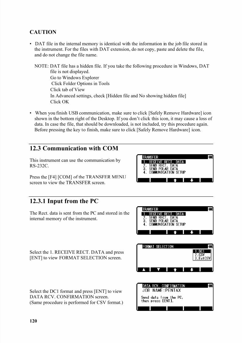
8/15/2019 r400v Man Ptl En
http://slidepdf.com/reader/full/r400v-man-ptl-en 121/142
120
CAUTION
• DAT file in the internal memory is identical with the information in the job file stored inthe instrument. For the files with DAT extension, do not copy, paste and delete the file,and do not change the file name.
NOTE: DAT file has a hidden file. If you take the following procedure in Windows, DATfile is not displayed.Go to Windows ExplorerClick Folder Options in Tools
Click tab of ViewIn Advanced settings, check [Hidden file and No showing hidden file]Click OK
• When you finish USB communication, make sure to click [Safely Remove Hardware] icon
shown in the bottom right of the Desktop. If you don’t click this icon, it may cause a loss ofdata. In case the file, that should be downloaded, is not included, try this procedure again.Before pressing the key to finish, make sure to click [Safely Remove Hardware] icon.
12.3 Communication with COM
This instrument can use the communication byRS-232C.
Press the [F4] [COM] of the TRANSFER MENUscreen to view the TRANSFER screen.
12.3.1 Input from the PC
The Rect. data is sent from the PC and stored in theinternal memory of the instrument.
Select the 1. RECEIVE RECT. DATA and press[ENT] to view FORMAT SELECTION screen.
Select the DC1 format and press [ENT] to viewDATA RCV. CONFIRMATION screen.(Same procedure is performed for CSV format.)
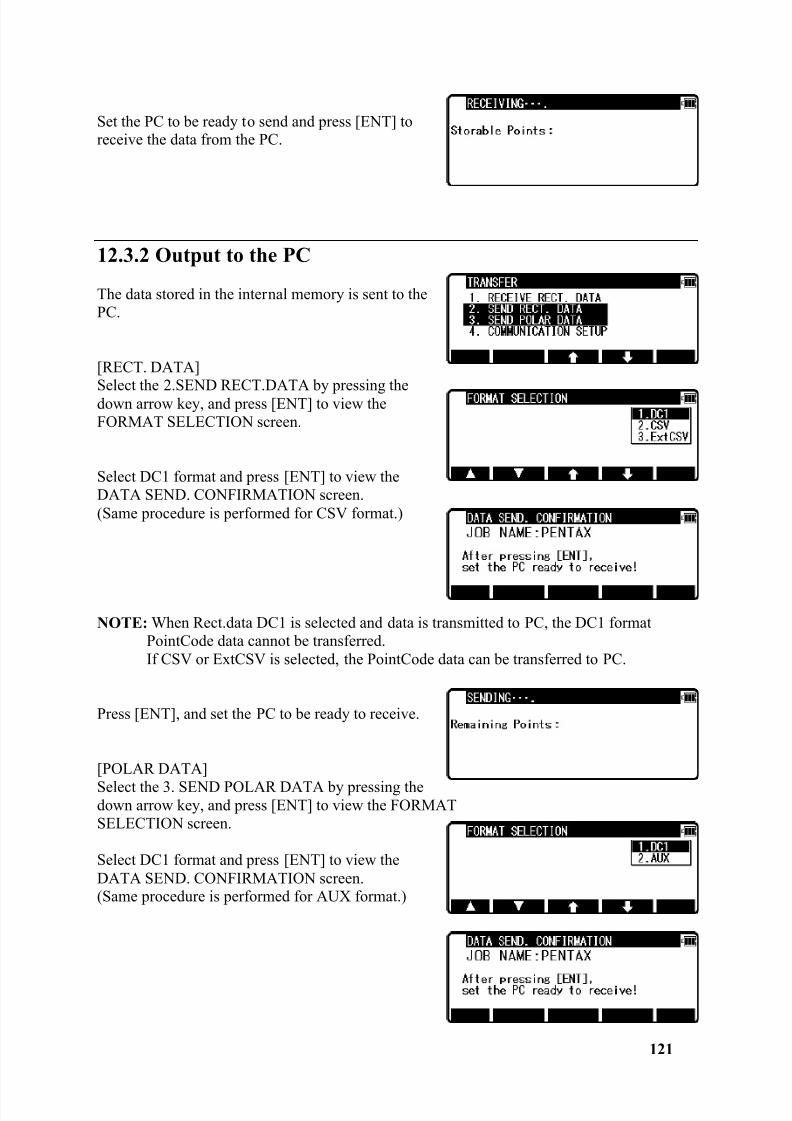
8/15/2019 r400v Man Ptl En
http://slidepdf.com/reader/full/r400v-man-ptl-en 122/142
121
Set the PC to be ready to send and press [ENT] toreceive the data from the PC.
12.3.2 Output to the PC
The data stored in the internal memory is sent to thePC.
[RECT. DATA]
Select the 2.SEND RECT.DATA by pressing thedown arrow key, and press [ENT] to view theFORMAT SELECTION screen.
Select DC1 format and press [ENT] to view theDATA SEND. CONFIRMATION screen.(Same procedure is performed for CSV format.)
NOTE: When Rect.data DC1 is selected and data is transmitted to PC, the DC1 formatPointCode data cannot be transferred.If CSV or ExtCSV is selected, the PointCode data can be transferred to PC.
Press [ENT], and set the PC to be ready to receive.
[POLAR DATA]Select the 3. SEND POLAR DATA by pressing thedown arrow key, and press [ENT] to view the FORMATSELECTION screen.
Select DC1 format and press [ENT] to view theDATA SEND. CONFIRMATION screen.(Same procedure is performed for AUX format.)
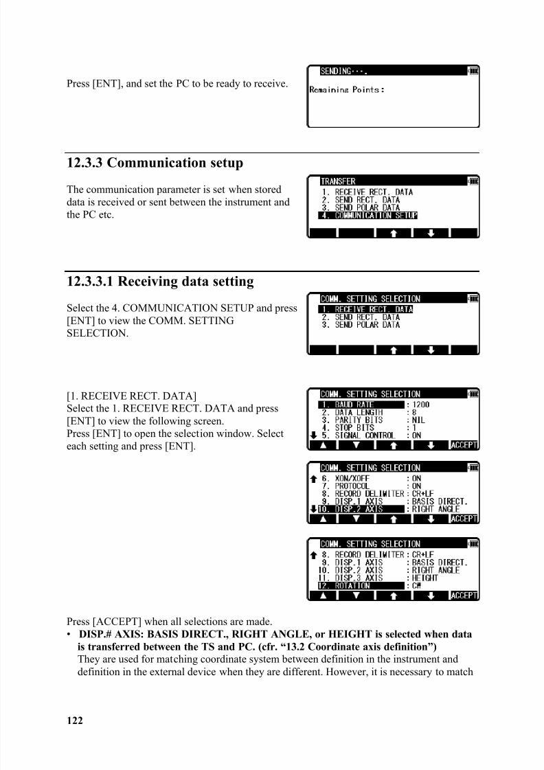
8/15/2019 r400v Man Ptl En
http://slidepdf.com/reader/full/r400v-man-ptl-en 123/142
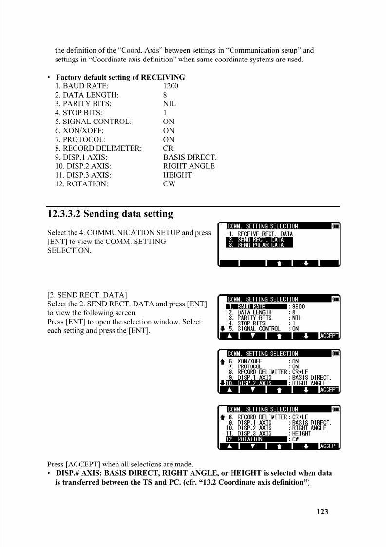
8/15/2019 r400v Man Ptl En
http://slidepdf.com/reader/full/r400v-man-ptl-en 124/142
123
the definition of the “Coord. Axis” between settings in “Communication setup” andsettings in “Coordinate axis definition” when same coordinate systems are used.
• Factory default setting of RECEIVING1. BAUD RATE: 1200
2. DATA LENGTH: 83. PARITY BITS: NIL4. STOP BITS: 15. SIGNAL CONTROL: ON6. XON/XOFF: ON7. PROTOCOL: ON8. RECORD DELIMETER: CR9. DISP.1 AXIS: BASIS DIRECT.10. DISP.2 AXIS: RIGHT ANGLE11. DISP.3 AXIS: HEIGHT12. ROTATION: CW
12.3.3.2 Sending data setting
Select the 4. COMMUNICATION SETUP and press[ENT] to view the COMM. SETTINGSELECTION.
[2. SEND RECT. DATA]Select the 2. SEND RECT. DATA and press [ENT]to view the following screen.Press [ENT] to open the selection window. Selecteach setting and press the [ENT].
Press [ACCEPT] when all selections are made.• DISP.# AXIS: BASIS DIRECT, RIGHT ANGLE, or HEIGHT is selected when data
is transferred between the TS and PC. (cfr. “13.2 Coordinate axis definition”)
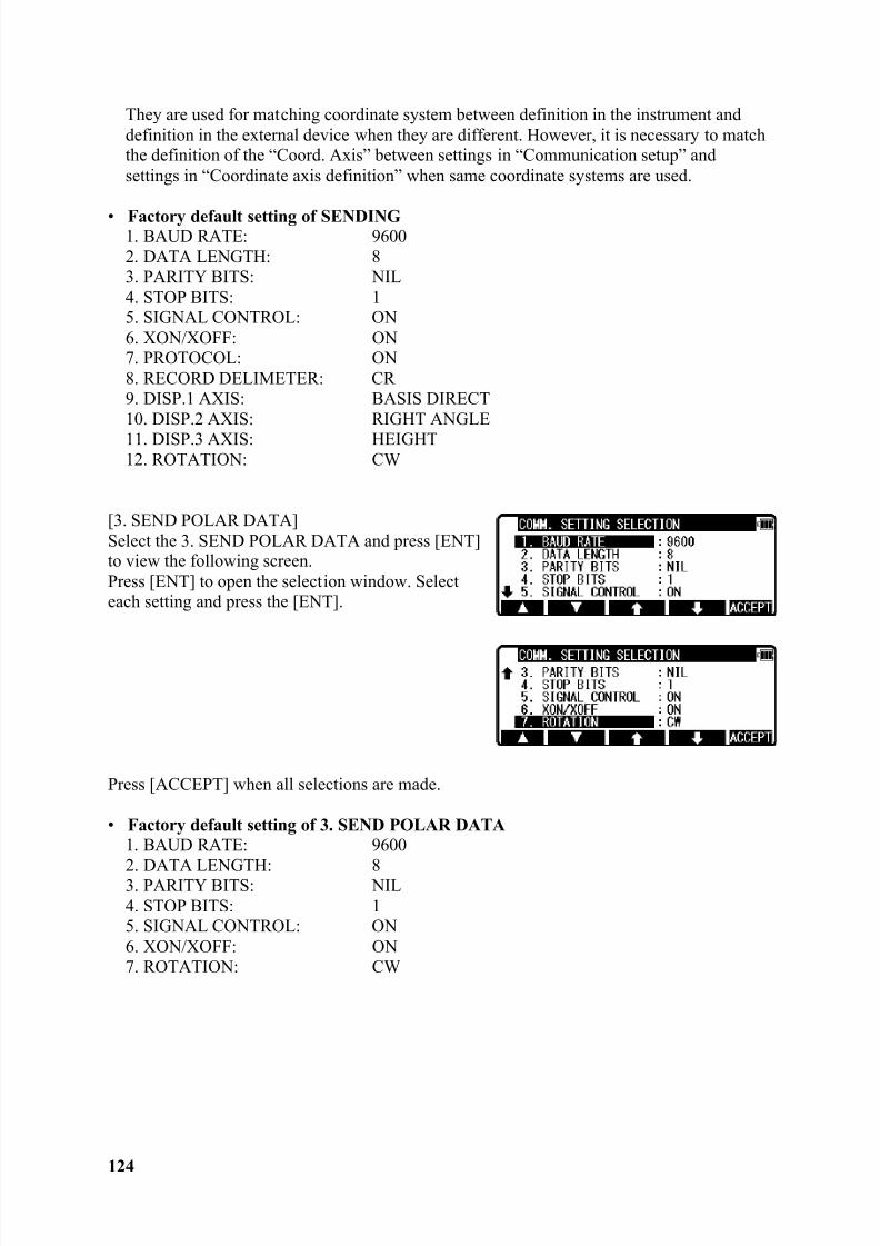
8/15/2019 r400v Man Ptl En
http://slidepdf.com/reader/full/r400v-man-ptl-en 125/142
8/15/2019 r400v Man Ptl En
http://slidepdf.com/reader/full/r400v-man-ptl-en 126/142
125
12.3.4 About DataLink DL-01 Software
DataLink DL-01 Software allows you to send collected data by R-400V to other devices,to receive coordinates data, and to convert the resulting files into a number of commonformats.
a) Recommendation for "PN".It is recommended that “PN” (Point Name) data should consist of less or equal to 4(one-byte) numeric characters to convert files with DL-01. Because, it may not beconverted properly if alphabetic characters or more than 5 (one-byte) numericcharacters are used for the “PN”.
b) Notes for the data transferring.Please be careful about following items for the data transfer with "DL-01".
b-1 Type of data, which can be transferred .With PTL, “POLAR DATA” can be transferred by “DC1” or “AUX” format.In addition, it is possible for DL-01 to receive/convert “POLAR DATA” with “DC1(DC-1Z) ” format.
b-2 Notes for unit .If you are requested to select unit when you convert data on DL-01, please select unitaccording to the settings on R-400V.
b-3 Limitation for each format .
Please, use “CSV” or “DC1( DC-1Z)” format to transfer data to/from R-400V.
Limitation for the "CSV" format .With the “CSV” format, “PN” and “PC (Point Code)”data that consists of less or equalto 15 (one-byte) characters can be transferred.
Limitations for the "DC1 (DC-1Z)" format.With “DC1 (DC-1Z)” format, the length of “PN” data should consist of less or equalto 11 (one-byte) characters. And with the “DC1 (DC-1Z)” format “PC” data cannot be transferred.
8/15/2019 r400v Man Ptl En
http://slidepdf.com/reader/full/r400v-man-ptl-en 127/142
126
b-4 Recommended communication settings on R-400V.Recommended settings for “COMM SETTING SELECTION” on R-400V specialfunction is as follows.
R-400V PC(DL-01) to “SEND RECT. DATA”1. BAUD RATE: 12002. DATA LENGTH: 83. PARITY BITS: NIL4. STOP BITS: 15. SIGNAL CONTROL: OFF6. XON/XOFF: OFF7. PROTOCOL: OFF for “CSV” format, ON for “DC1 (DC-1Z)” format8. RECORD DELIMETER: CRSubsequent items: As you like.
R-400V PC(DL-01) to “SEND POLAR DATA”1. BAUD RATE: 1200-96002. DATA LENGTH: 83. PARITY BITS: NIL4. STOP BITS: 15. SIGNAL CONTROL: OFF6. XON/XOFF: OFF7. ROTATION: As you like.
PC(DL-01) R-400V to “RECEIVE RECT. DATA”1. BAUD RATE: 12002. DATA LENGTH: 83. PARITY BITS: NIL4. STOP BITS: 15. SIGNAL CONTROL: OFF6. XON/XOFF: OFF7. PROTOCOL: OFF for “CSV” format, ON for “DC1 (DC-1Z)” format8. RECORD DELIMETER: CR9. Subsequent items: As you like.
Please note that these settings should be common with DL-01's.
b-5 Recommended communication settings on DL-01 .To configure DL-01 Communication setting, please read “Configuring the software”in the Help topics of DL-01 and select values as follows:
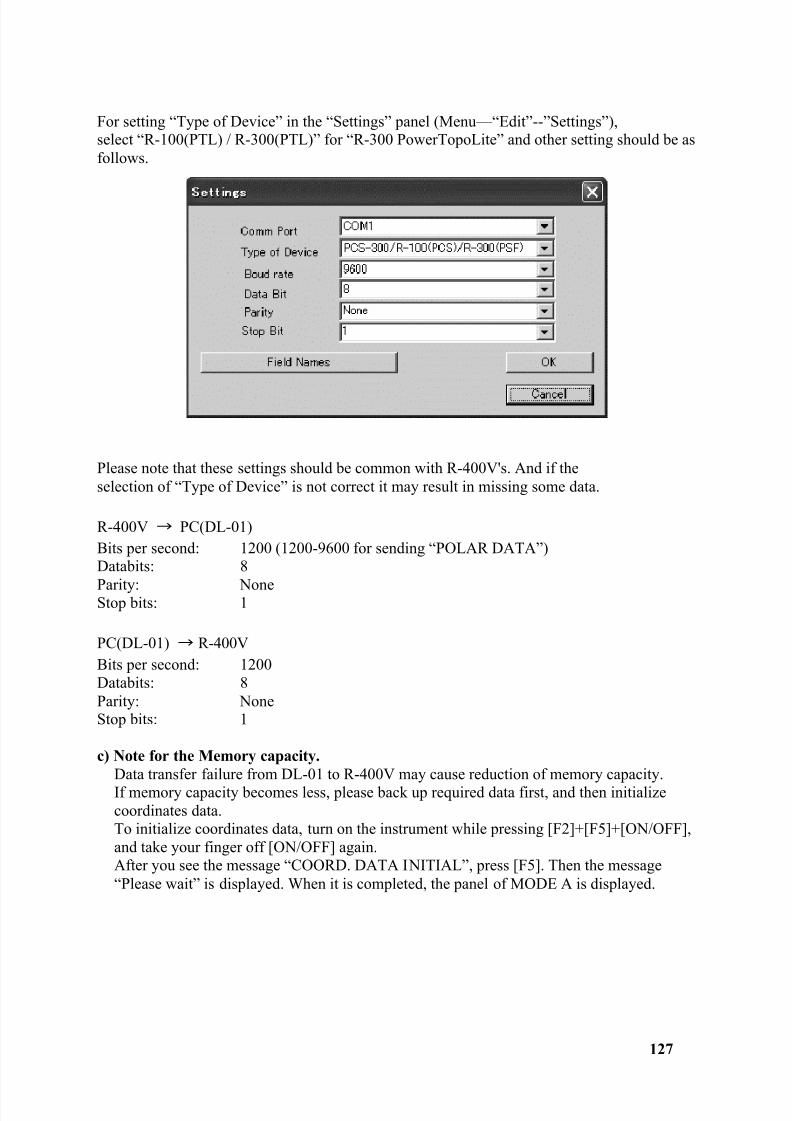
8/15/2019 r400v Man Ptl En
http://slidepdf.com/reader/full/r400v-man-ptl-en 128/142
127
For setting “Type of Device” in the “Settings” panel (Menu—“Edit”--”Settings”),select “R-100(PTL) / R-300(PTL)” for “R-300 PowerTopoLite” and other setting should be asfollows.
Please note that these settings should be common with R-400V's. And if theselection of “Type of Device” is not correct it may result in missing some data.
R-400V PC(DL-01)Bits per second: 1200 (1200-9600 for sending “POLAR DATA”)Databits: 8
Parity: NoneStop bits: 1
PC(DL-01) R-400VBits per second: 1200Databits: 8Parity: NoneStop bits: 1
c) Note for the Memory capacity.Data transfer failure from DL-01 to R-400V may cause reduction of memory capacity.If memory capacity becomes less, please back up required data first, and then initializecoordinates data.To initialize coordinates data, turn on the instrument while pressing [F2]+[F5]+[ON/OFF],and take your finger off [ON/OFF] again.After you see the message “COORD. DATA INITIAL”, press [F5]. Then the message“Please wait” is displayed. When it is completed, the panel of MODE A is displayed.
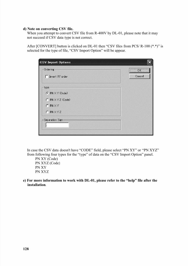
8/15/2019 r400v Man Ptl En
http://slidepdf.com/reader/full/r400v-man-ptl-en 129/142
128
d) Note on converting CSV file.When you attempt to convert CSV file from R-400V by DL-01, please note that it maynot succeed if CSV data type is not correct.
After [CONVERT] button is clicked on DL-01 then “CSV files from PCS/ R-100 (*.*)” isselected for the type of file, “CSV Import Option” will be appear.
In case the CSV data doesn't have “CODE” field, please select “PN XY” or “PN XYZ”from following four types for the “type” of data on the “CSV Import Option” panel.
PN XY (Code)PN XYZ (Code)PN XYPN XYZ
e) For more information to work with DL-01, please refer to the “help” file after the
installation .
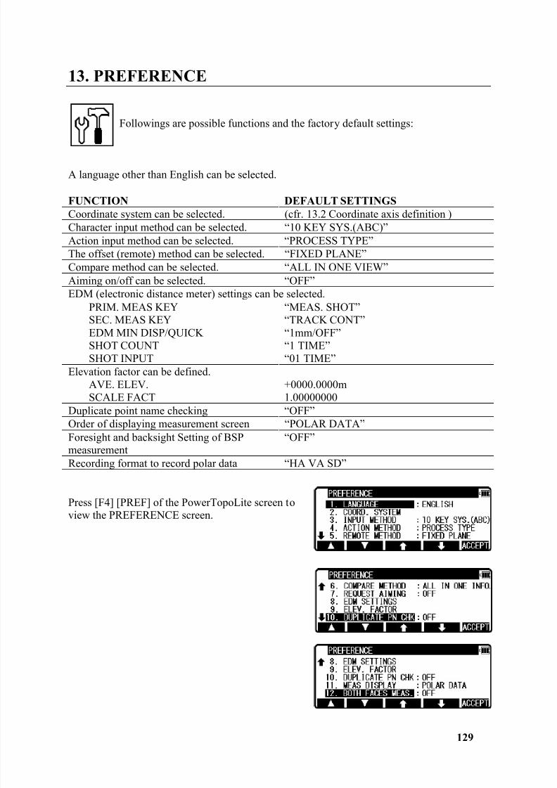
8/15/2019 r400v Man Ptl En
http://slidepdf.com/reader/full/r400v-man-ptl-en 130/142
129
13. PREFERENCE
Followings are possible functions and the factory default settings:
A language other than English can be selected.
FUNCTION DEFAULT SETTINGS Coordinate system can be selected. (cfr. 13.2 Coordinate axis definition )Character input method can be selected. “10 KEY SYS.(ABC)”Action input method can be selected. “PROCESS TYPE”The offset (remote) method can be selected. “FIXED PLANE”Compare method can be selected. “ALL IN ONE VIEW”Aiming on/off can be selected. “OFF”EDM (electronic distance meter) settings can be selected.
PRIM. MEAS KEYSEC. MEAS KEYEDM MIN DISP/QUICKSHOT COUNTSHOT INPUT
“MEAS. SHOT”“TRACK CONT”“1mm/OFF”“1 TIME”“01 TIME”
Elevation factor can be defined.AVE. ELEV.SCALE FACT
+0000.0000m1.00000000
Duplicate point name checking “OFF”Order of displaying measurement screen “POLAR DATA”Foresight and backsight Setting of BSPmeasurement
“OFF”
Recording format to record polar data “HA VA SD”
Press [F4] [PREF] of the PowerTopoLite screen toview the PREFERENCE screen.
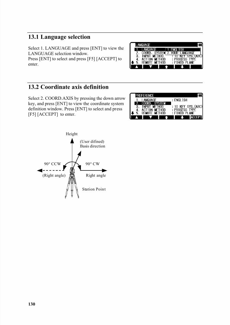
8/15/2019 r400v Man Ptl En
http://slidepdf.com/reader/full/r400v-man-ptl-en 131/142
130
13.1 Language selection
Select 1. LANGUAGE and press [ENT] to view theLANGUAGE selection window.Press [ENT] to select and press [F5] [ACCEPT] toenter.
13.2 Coordinate axis definition
Select 2. COORD.AXIS by pressing the down arrowkey, and press [ENT] to view the coordinate systemdefinition window. Press [ENT] to select and press
[F5] [ACCEPT] to enter.
Height
(User difined)Basis direction
Right angle
90° CW
Station Poin t
90° CCW
(Right angle)
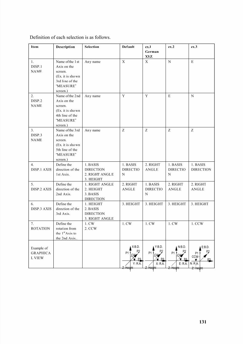
8/15/2019 r400v Man Ptl En
http://slidepdf.com/reader/full/r400v-man-ptl-en 132/142
131
Definition of each selection is as follows.
Item Description Selection Default ex.1GermanXYZ
ex.2 ex.3
1.DISP.1 NAME
Name of the 1 stAxis on thescreen.(Ex. it is sho wn3rd li ne of the“MEASURE ” screen.)
Any name X X N E
2.DISP.2 NAME
Name of the 2ndAxis on thescreen.(Ex. it is sho wn4th line of the
“MEASURE ” screen.)
Any name Y Y E N
3.DISP.3 NAME
Name of the 3rdAxis on thescreen.(Ex. it is sho wn5th line of the“MEASURE ” screen.)
An y name Z Z Z Z
4.DISP.1 AXIS
Define thedirection of the1st Axis.
1. BASISDIRECTION2. RIGHT ANGL E
3. HEIGHT
1. BASISDIRECTIO N
2. RIGHTANGLE
1. BASISDIRECTIO N
1. BASISDIRECTION
5.DISP.2 AXIS
Define thedirection of the2nd Axis.
1. RIGHT ANGLE2. HEIGHT3. BASISDIRECTION
2. RIGHTANGLE
1. BASISDIRECTIO N
2. RIGHTANGLE
2. RIGHTANGLE
6.DISP.3 AXIS
Define thedirection of the3rd Axis.
1. HEIGHT2. BASISDIRECTION3. RIGHT ANGLE
3. HEIGHT 3. HEIGHT 3. HEIGHT 3. HEIGHT
7.ROTATION
Define therotat ion fromthe 1 st Axis tothe 2nd Axis..
1. CW2. CCW
1. CW 1. CW 1. CW 1. CCW
Example ofGRAPHICAL VIEW
CW
X:B.D.
P1 P2
P3 Y: R.A.
Z: Height
CCW
E:B.D.
P1 P2
P3 N: R.A.
Z: Height
CW
Y:B.D.
P1 P2
P3 X: R.A.
Z: Height
CW
N:B.D.
P1 P2
P3 E: R.A.
Z: Height
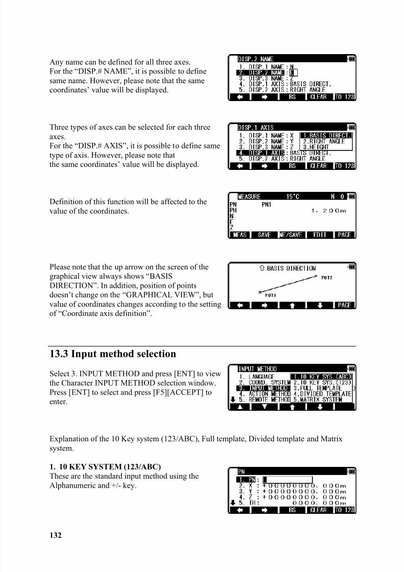
8/15/2019 r400v Man Ptl En
http://slidepdf.com/reader/full/r400v-man-ptl-en 133/142
132
Any name can be defined for all three axes.For the “DISP.# NAME”, it is possible to definesame name. However, please note that the samecoordinates’ value will be displayed.
Three types of axes can be selected for each threeaxes.For the “DISP.# AXIS”, it is possible to define sametype of axis. However, please note thatthe same coordinates’ value will be displayed.
Definition of this function will be affected to thevalue of the coordinates.
Please note that the up arrow on the screen of thegraphical view always shows “BASISDIRECTION”. In addition, position of pointsdoesn’t change on the “GRAPHICAL VIEW”, butvalue of coordinates changes according to the settingof “Coordinate axis definition”.
13.3 Input method selection
Select 3. INPUT METHOD and press [ENT] to viewthe Character INPUT METHOD selection window.Press [ENT] to select and press [F5][ACCEPT] toenter.
Explanation of the 10 Key system (123/ABC), Full template, Divided template and Matrixsystem.
1. 10 KEY SYSTEM (123/ABC)These are the standard input method using theAlphanumeric and +/- key.
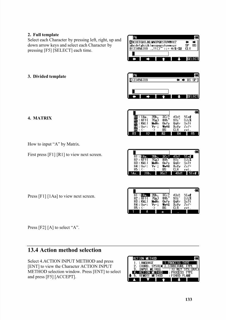
8/15/2019 r400v Man Ptl En
http://slidepdf.com/reader/full/r400v-man-ptl-en 134/142
133
2. Full templateSelect each Character by pressing left, right, up anddown arrow keys and select each Character by pressing [F5] [SELECT] each time.
3. Divided template
4. MATRIX
How to input “A” by Matrix.
First press [F1] [R1] to view next screen.
Press [F1] [1Aa] to view next screen.
Press [F2] [A] to select “A”.
13.4 Action method selection
Select 4.ACTION INPUT METHOD and press[ENT] to view the Character ACTION INPUTMETHOD selection window. Press [ENT] to selectand press [F5] [ACCEPT].
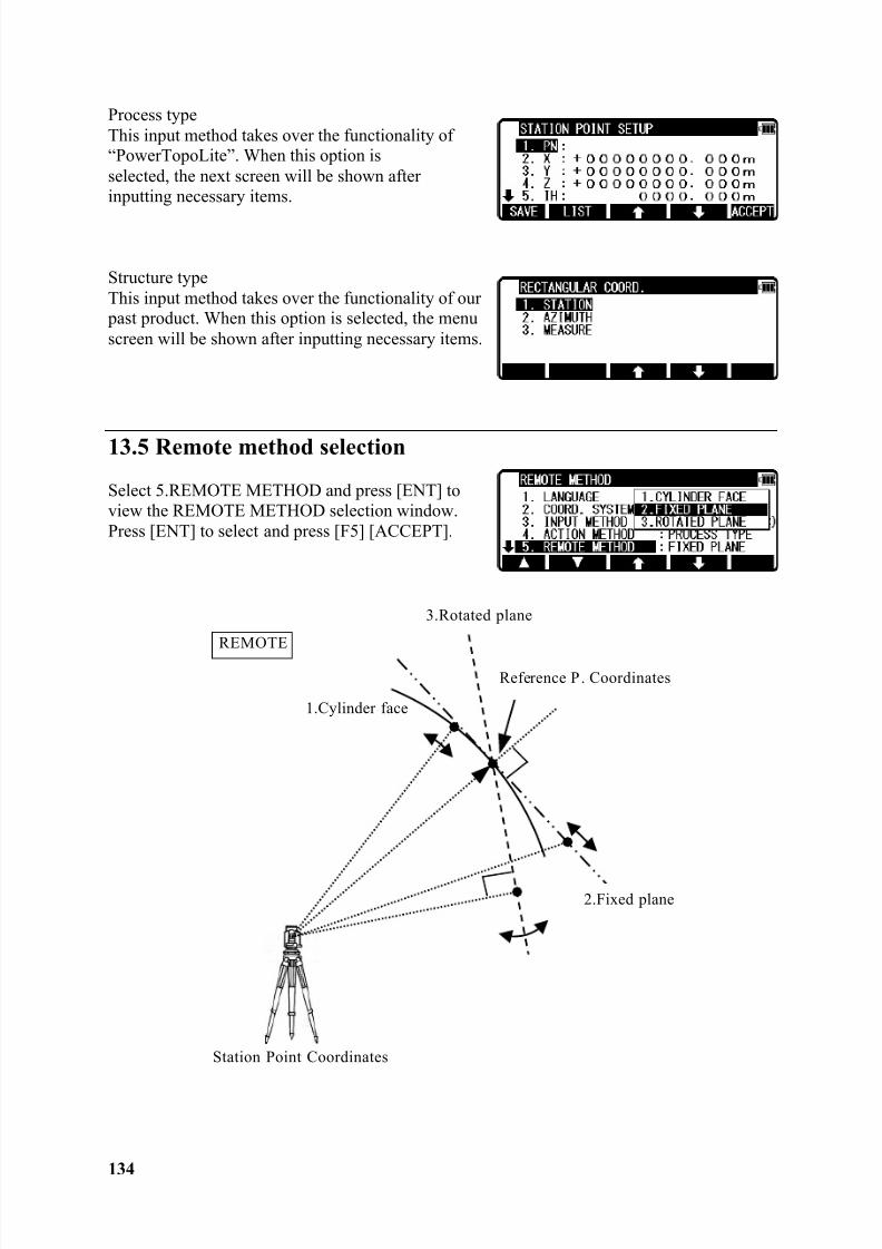
8/15/2019 r400v Man Ptl En
http://slidepdf.com/reader/full/r400v-man-ptl-en 135/142
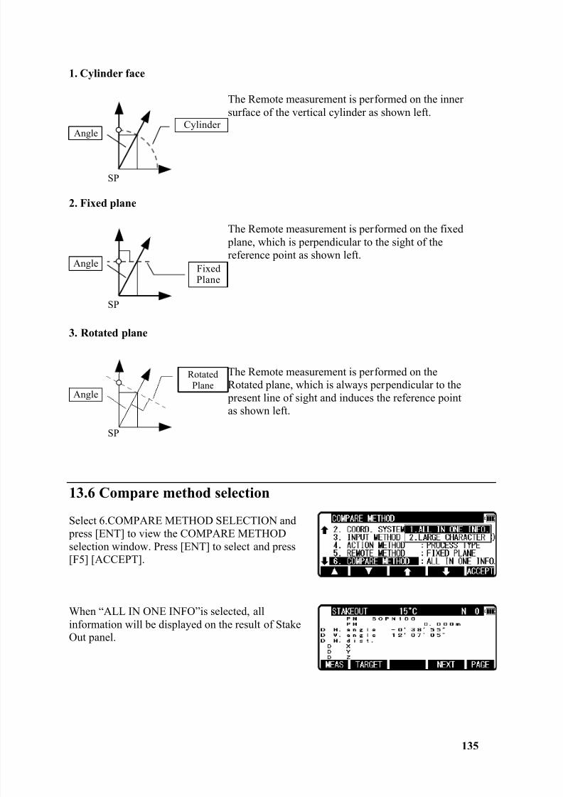
8/15/2019 r400v Man Ptl En
http://slidepdf.com/reader/full/r400v-man-ptl-en 136/142
135
1. Cylinder face
The Remote measurement is performed on the innersurface of the vertical cylinder as shown left.
2. Fixed plane
The Remote measurement is performed on the fixed plane, which is perpendicular to the sight of thereference point as shown left.
3. Rotated plane
The Remote measurement is performed on theRotated plane, which is always perpendicular to the present line of sight and induces the reference pointas shown left.
13.6 Compare method selection
Select 6.COMPARE METHOD SELECTION and press [ENT] to view the COMPARE METHODselection window. Press [ENT] to select and press[F5] [ACCEPT].
When “ALL IN ONE INFO”is selected, allinformation will be displayed on the result of StakeOut panel.
CylinderAngle
FixedPlane
Angle
RotatedPlane
SP
Angle
SP
SP
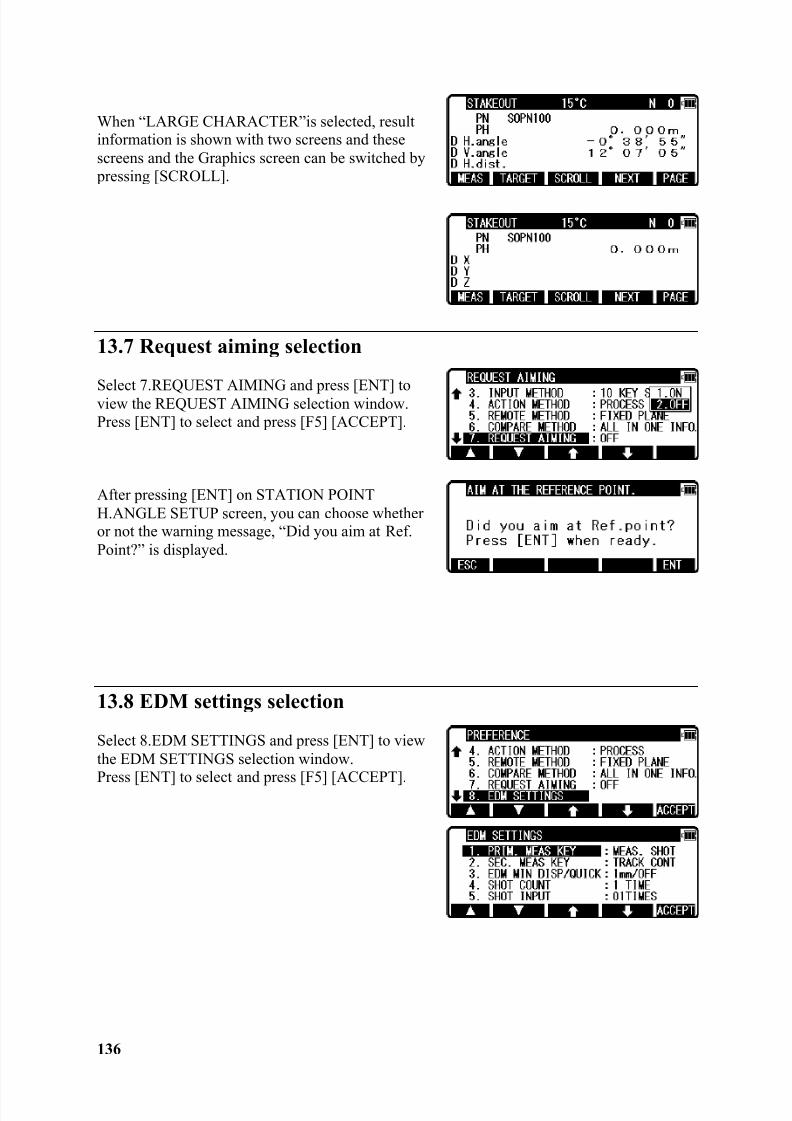
8/15/2019 r400v Man Ptl En
http://slidepdf.com/reader/full/r400v-man-ptl-en 137/142
136
When “LARGE CHARACTER”is selected, resultinformation is shown with two screens and thesescreens and the Graphics screen can be switched by pressing [SCROLL].
13.7 Request aiming selection
Select 7.REQUEST AIMING and press [ENT] toview the REQUEST AIMING selection window.Press [ENT] to select and press [F5] [ACCEPT].
After pressing [ENT] on STATION POINTH.ANGLE SETUP screen, you can choose whetheror not the warning message, “Did you aim at Ref.Point?” is displayed.
13.8 EDM settings selection
Select 8.EDM SETTINGS and press [ENT] to viewthe EDM SETTINGS selection window.Press [ENT] to select and press [F5] [ACCEPT].
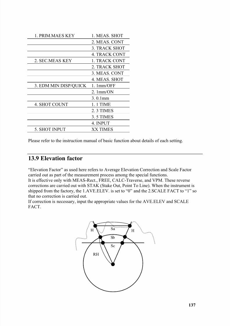
8/15/2019 r400v Man Ptl En
http://slidepdf.com/reader/full/r400v-man-ptl-en 138/142
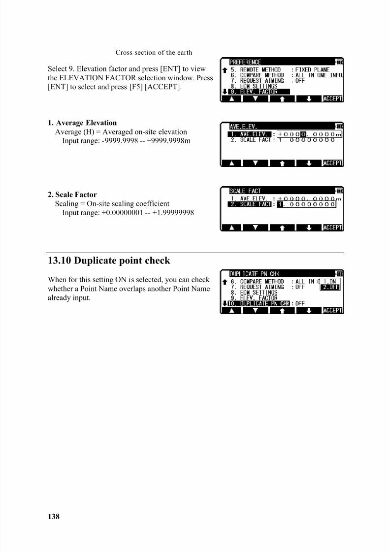
8/15/2019 r400v Man Ptl En
http://slidepdf.com/reader/full/r400v-man-ptl-en 139/142
138
Select 9. Elevation factor and press [ENT] to viewthe ELEVATION FACTOR selection window. Press[ENT] to select and press [F5] [ACCEPT].
1. Average ElevationAverage (H) = Averaged on-site elevation
Input range: -9999.9998 -- +9999.9998m
2. Scale FactorScaling = On-site scaling coefficient
Input range: +0.00000001 -- +1.99999998
13.10 Duplicate point check
When for this setting ON is selected, you can check
whether a Point Name overlaps another Point Namealready input.
Cross section of the earth
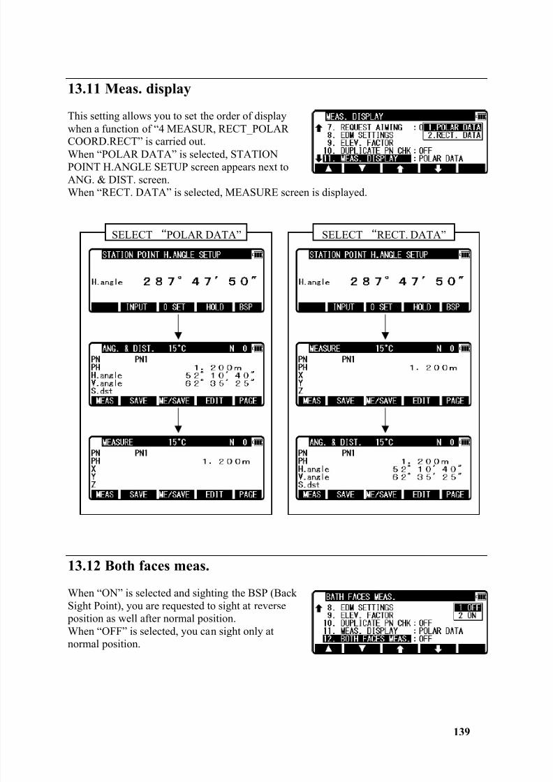
8/15/2019 r400v Man Ptl En
http://slidepdf.com/reader/full/r400v-man-ptl-en 140/142
139
13.11 Meas. display
This setting allows you to set the order of displaywhen a function of “4 MEASUR, RECT_POLARCOORD.RECT” is carried out.When “POLAR DATA” is selected, STATIONPOINT H.ANGLE SETUP screen appears next toANG. & DIST. screen.When “RECT. DATA” is selected, MEASURE screen is displayed.
13.12 Both faces meas.
When “ON” is selected and sighting the BSP (BackSight Point), you are requested to sight at reverse position as well after normal position.When “OFF” is selected, you can sight only atnormal position.
SELECT POLAR DATA” SELECT RECT. DATA”
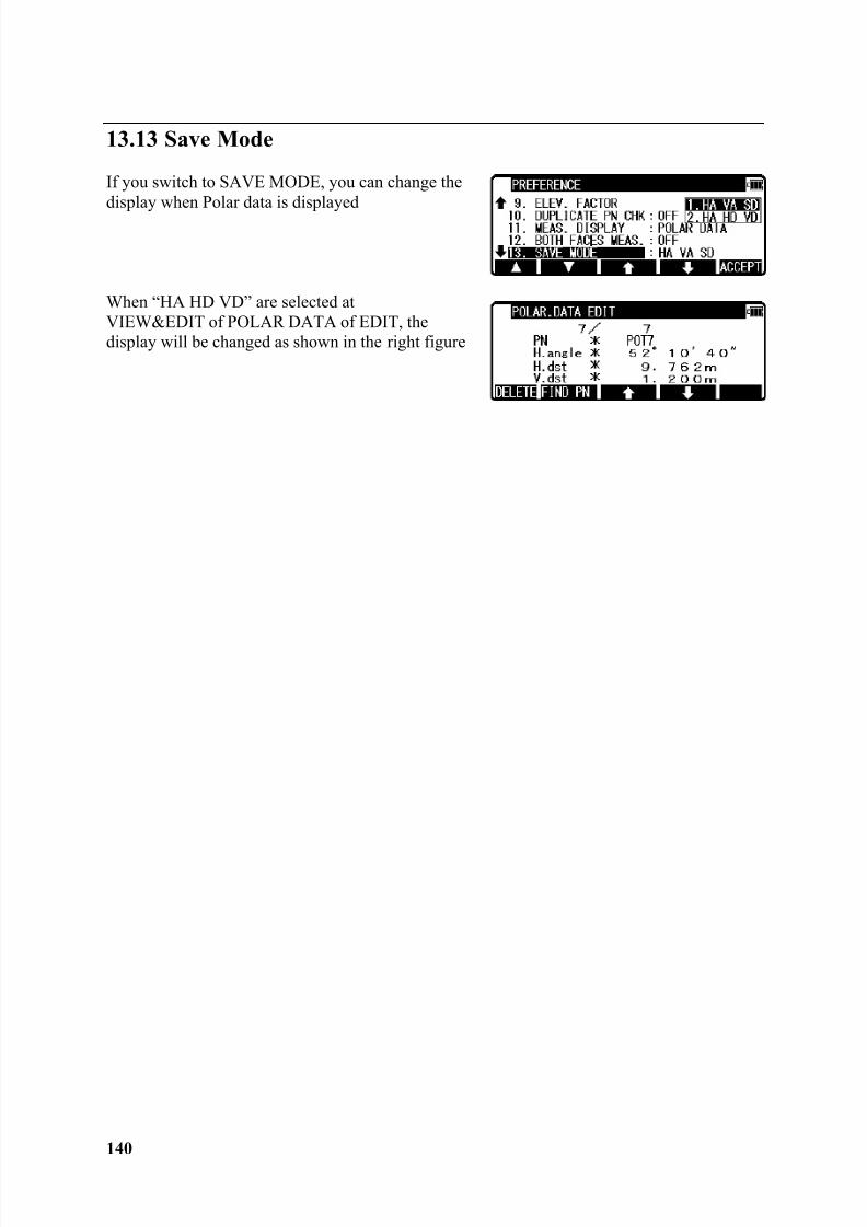
8/15/2019 r400v Man Ptl En
http://slidepdf.com/reader/full/r400v-man-ptl-en 141/142

8/15/2019 r400v Man Ptl En
http://slidepdf.com/reader/full/r400v-man-ptl-en 142/142