Embed Size (px)
Citation preview

AboveAir™ Same-Face Ceiling A/C’sAboveAir Technologies (AHK-L30)1
EvaporatorAir Inlet Evaporator
Air Outlet
HKHKHKHKHK ™-Horizontal, above-the-ceiling air conditioners (AHK-L30)
Features & Benefits• 1 to 15 Ton Capacities
• ComfortCool™- General Office Spaces- Conference Rooms- Restaurants / Retail Stores
• PrecisionCool™- Computer / Server Rooms- Telecom Rooms- Labs / Hospitals
• Ducted, Same-Face, Straight-Thru & 90° Air Patterns
• DX Air, Water & Glycol Cooled,Chilled Water & Free-Cooling
• Total Temp & Humidity Control- Optional Steam Humidifier- Optional Heat/Reheat via
Electric, Hot Gas, Hot Water,Steam or Heat Pump
• Microprocessor Controls & More!
1 to 15 TonsDucted, High-Static
Belt-Driven
HKHKHKHKHK
TM HorizontalHigh Static Packaged & Split
Ceiling Mounted Air Conditioners(DX & CW Systems)
Engineering Manual
MEA230-06-E
R410aR410aR410aR410aR410a

AboveAir™ Same-Face Ceiling A/C’s AboveAir Technologies (AHK-L30)2
EvaporatorAir Inlet Evaporator
Air Outlet
ACCESS
PANELE-Box
CondenserAir Outlet Condenser
Air Inlet
ACCESS
PANEL
EvaporatorAir Inlet Evaporator
Air Outlet
ACCESS
PANELE-Box
EvaporatorAir Outlet
CondenserAir Outlet
EvaporatorAir Inlet
CondenserAir Inlet
ACCESS
PANEL
ACCESS
PANEL
E-BoxE-Box
Introduction
INTRODUCTION
AboAboAboAboAbovvvvveeeeeAirAirAirAirAir™™™™™ ceiling mounted airconditioners are the space savingenvironmental control solution toyour comfort and precision coolingneeds. Available in a wide varietyof cooling methods and cabinetconfigurations including a full rangeof options, AboAboAboAboAbovvvvveeeeeAirAirAirAirAir™™™™™ ceilingA/C’s are a step above!
R410a Refrigerant Hidden above-the-ceiling installation Space saving air pattern options Variety of cooling methods Self-contained & split systems Flexible options and accessories Energy efficient operation Low sound operation
ContentsIntroduction ................................................ 2
Features and Benefits ............................... 3
Performance DataDX Air Cooled, 1-5 Tons .................................. 4-5DX Air Cooled, 6-15 Tons ................................ 6-7DX Water Cooled, 1-5 Tons ................................. 8DX Water Cooled, 6-15 Tons ............................... 9DX Glycol Cooled, 1-5 Tons .............................. 10DX Glycol Cooled, 6-15 Tons .............................11Chilled Water Air Handlers, 1-15 Tons .............. 12Hot Water & Steam Heat ................................... 13
Electrical Data ..................................... 14-23
Guide Specifications .......................... 24-31
Dimensional Data ................................ 32-38
Model Nomenclature ............................... 39
Approximate Unit Weights (lbs) .............. 39
AAC/P-( )DX - Air CooledSelf-Contained
AH/AEC/P & XCU/XCX-( )DX - Air Cooled Split with Centrifugal
Blower Indoor / Outdoor RemoteCondensing Unit & Condensers
AWC/P & AGC/P-( )DX - Water/Glycol
Cooled Self-Contained(split available)
AH/AEC/P & XPU/XP1-( )DX - Air Cooled Split with PropellerFan Outdoor Remote Condensing
Unit & Condensers
ACC/P-( )Chilled Water
Air Handling Units
Air Cooled
Water/Glycol Cooled(plus Free-Cooling)
Chilled Water Systems
EvaporatorAir Inlet Evaporator
Air Outlet
ACCESS
PANELE-Box
EvaporatorAir Outlet
EvaporatorAir Inlet
ACCESS
PANEL
ACCESS
PANEL

AboveAir™ Same-Face Ceiling A/C’sAboveAir Technologies (AHK-L30)3Features & Benefits
FEATURES & BENEFITS
AboveAir™™™™™ ducted high static belt-driven ceiling mounted air conditioners canbe configured for various applications:
Select Options:• Digital Heat/Cool Thermostats• Temp & Humid Microprocessor Controls with
Alarms and Optional BMS Communications• Steam Canister Humidifier• Heating Mode with Electric, Hot Water,
Steam or Heat Pump Heating• Dehumidification Mode with Reheat• High Efficiency Air Filtration• Low Ambient Head Pressure Control• 2 & 3-way 150 psig or 350 psig Water/
Glycol Cooled Regulating Valves• High Static Belt-Drive Blowers (up to 2” ESP)• Hot Gas Bypass• Free-Cooling: Air Side & Water/Glycol Side
Economizer Systems
Select Accessories:• Condensate Pumps• Main Power Electrical Disconnects• Firestats• Smoke Detectors• Remote Water-Leak Detectors• Compressor Sound Jackets• Hanging Vibration Isolators• Glycol Pump Packages & Drycoolers• ... and more!
Packaged & Split Systems
MEA230-06-E
EvaporatorAir Inlet Evaporator
Air Outlet
ACCESS
PANELE-Box
EvaporatorAir Inlet
EvaporatorAir Outlet
EvaporatorAir InletEvaporator
Air Outlet
Ducted Straight-Thru
Ducted Same-Face
Ducted 90° / Right-Angle

AboveAir™ Same-Face Ceiling A/C’s AboveAir Technologies (AHK-L30)4
DX - Air Cooled, (HK1TM, 1-5 Tons) - Performance Data
Performance Data
Nominal Size 1.0 Ton 1.5 Tons 2.0 Tons 3.0 Tons 4.0 Tons 5.0 Tons
ComfortCoolTM Model AAC/AEC/AHC-012 AAC/AEC/AHC-018 AAC/AEC/AHC-024 AAC/AEC/AHC-036 AAC/AEC/AHC-048 AAC/AEC/AHC-060
AIRCOOLED
DX
StdCFM
80°F DB / 67°F WB, 50% RH Total BTUH 14,500 20,300 27,800 40,700 53,700 67,700 Sensible BTUH 10,300 14,600 20,400 30,100 40,000 50,200
75°F DB / 62.5°F WB, 50% RH Total BTUH 13,300 18,600 25,500 37,400 49,400 62,300
Sensible BTUH 10,100 14,300 20,000 29,600 39,300 49,300
72°F DB / 60°F WB, 50% RH Total BTUH 12,700 17,700 24,400 35,800 47,100 59,600
Sensible BTUH 9,900 14,000 19,900 29,000 38,900 48,300
PrecisionCoolTM Model AAP/AEP/AHP-012 AAP/AEP/AHP-018 AAP/AEP/AHP-024 AAP/AEP/AHP-036 AAP/AEP/AHP-048 AAP/AEP/AHP-060
AIRCOOLED
DX
OPTCFM
80°F DB / 67°F WB, 50% RH Total BTUH 15,000 20,900 28,800 42,000 56,600 69,700 Sensible BTUH 11,400 16,200 23,200 33,600 48,600 56,100
75°F DB / 62.5°F WB, 50% RH Total BTUH 13,800 19,200 26,500 38,900 52,200 64,700 Sensible BTUH 11,300 16,000 22,900 33,500 48,000 55,80072°F DB / 60°F WB, 50% RH Total BTUH 13,200 18,500 25,400 37,100 49,900 61,800 Sensible BTUH 11,200 16,000 22,500 32,800 47,000 54,700
GENERAL SHARED DATA
ALL DXMODELS
Electric Heat and/or Reheat (Factory Installed) - BTUH include standard evaporator motor heat, (Optional)
CapacityBTUH 17,675 17,675 18,245 36,490 36,490 37,635
KW 5.2 5.2 5.3 10.7 10.7 11.0 Stages NO 1 1 1 1 1 1 Type TXT Fin-Tube Fin-Tube Fin-Tube Fin-Tube Fin-Tube Fin-Tube
Hot Gas Reheat - (Optional) Capacity BTUH 10,110 14,140 19,380 28,430 37,550 47,350
Hot Water & Steam Heating - (Optional) Capacity See Page 13 for Complete Hot Water & Steam Heating Coil Performance Data Steam Canister Humidifier - (Optional) Steam Capacity LBS/HR 5 5 5 5 10 10 Power Input KW 1.79 1.79 1.79 1.79 3.4 3.4
Evaporator Blower / Motor - Belt Drive, DWDI Centrifugal
Std Airflow Rate CFM 400 600 800 1,200 1,600 2,000
Std Blower Motor HP 1/3 1/3 1/2 3/4 3/4 1 Opt Airflow Rate CFM 500 750 1,000 1,500 2,250 2,500
Opt Blower Motor HP 1/3 1/3 1/2 3/4 1 1-1/2
E.S.P. IN WG 0.75 0.75 0.75 0.75 0.75 0.75
Blower Diameter IN 10 X 8 10 X 8 10 X 8 10 X 8 12 X 9 12 X 9 Evaporator Coil - Aluminum Fin, Copper Tube
Rows NO 3 3 4 4 4 4 Face Area FT2 2.0 2.0 2.9 2.9 5.1 5.1
Filters - 30% Dust Spot Efficient
(Qty.) Nom. Size (NO) IN (1) 18 x 24 x 2 (1) 18 x 24 x 2 (1) 18 x 24 x 2 (1) 18 x 24 x 2 (2) 16 x 24 x 2 (2) 16 x 24 x 2
Compressor - Heat Pump Duty Hermetic
Type TXT Scroll Scroll Scroll Scroll Scroll Scroll
(Qty.) Horsepower (NO) HP (1) 1.25 (1) 1.5 (1) 2.0 (1) 3.0 (1) 4.0 (1) 5.0 Connection Sizes Condensate Drain FPT IN 3/4 3/4 3/4 3/4 3/4 3/4 Humidifier Inlet IN OD 1/4 1/4 1/4 1/4 1/4 1/4

AboveAir™ Same-Face Ceiling A/C’sAboveAir Technologies (AHK-L30)5Performance Data
H e a t R e j e c t i o n D a t a
C o n n e c t i o n D a t a
Nominal Size 1.0 Ton 1.5 Tons 2.0 Tons 3.0 Tons 4.0 Tons 5.0 TonsModel Size 012 018 024 036 048 060
DX - AIR COOLED CONDENSER DATA
AIRCOOLED
DX
Indoor, Remote Centrifugal Blower Air Cooled Condenser & Condensing Unit Data - (XCU & XCX Models)
Remote Condensing Unit Model XCU-012 XCU-018 XCU-024 XCU-036 XCU-048 XCU-060 Remote Condenser Model XCX-012 XCX-018 XCX-024 XCX-036 XCX-048 XCX-060
Airflow RateCFM 1,000 1,200 1,400 2,000 2,500 3,250
IN ESP 0.5 0.5 0.5 0.5 0.5 0.5
Blower Motor HP 1/2 3/4 3/4 1 1-1/2 2
Blower Diameter IN 10 x 8 10 x 8 10 x 8 12 x 9 15 x 10 15 x 10
Blower Type BD - Centrifugal BD - Centrifugal BD - Centrifugal BD - Centrifugal BD - Centrifugal BD - Centrifugal
Coil Face Area FT2 2.5 2.5 4.1 4.1 6.5 6.5
Rows NO 4 4 4 4 4 4
Outdoor, Remote Propeller Fan Air Cooled Condensing Units & Condensers - (XPU & XP1 models)
Remote Condensing Unit Model XPU-012 XPU-018 XPU-024 XPU-036 XPU-048 XPU-060
Remote Condenser Model XP1-012 XP1-018 XP1-024 XP1-036 XP1-048 XP1-060
Airflow RateCFM 1,792 2,218 2,218 3,167 3,365 3,365
IN ESP Free Discharge Free Discharge Free Discharge Free Discharge Free Discharge Free Discharge
Fan Motor (NO) HP (1) 1/12 (1) 1/10 (1) 1/10 (1) 1/5 (1) 1/4 (1) 1/4
Fan Type DD - Propeller DD - Propeller DD - Propeller DD - Propeller DD - Propeller DD - Propeller
Coil Face Area FT2 8.4 8.4 9.8 17.25 19.4 15.09
Rows NO 1 1 1 1 1 2
Nominal Size 1.0 Ton 1.5 Tons 2.0 Tons 3.0 Tons 4.0 Tons 5.0 TonsModel Size 012 018 024 036 048 060
DX - AIR COOLED REFRIGERANT (R407C & R410a) CONNECTION DATA
AIRCOOLED
DX Split Air Handling Units & Indoor, Centrifugal Blower Remote Air Cooled Condensing Units - (AHC/P & XCU models)
Liquid Line OD IN (1) 3/8 (1) 3/8 (1) 3/8 (1) 3/8 (1) 3/8 (1) 3/8 Suction Line OD IN (1) 3/4 (1) 3/4 (1) 3/4 (1) 3/4 (1) 7/8 (1) 7/8
DX Split Evaporators & Indoor Remote Centrifugal Air Cooled Condensers - (AEC/P & XCX models)
Liquid Line OD IN (1) 3/8 (1) 3/8 (1) 3/8 (1) 3/8 (1) 3/8 (1) 3/8 Hot Gas Line OD IN (1) 1/2 (1) 1/2 (1) 1/2 (1) 1/2 (1) 5/8 (1) 5/8
Outdoor, Propeller Fan Remote Air Cooled Condensers & Condensing Units - (XP1 w/ Liquid & Hot Gas Lines and XPU w/ Liquid & Suction Lines)
Liquid Line OD IN (1) 3/8 (1) 3/8 (1) 3/8 (1) 3/8 (1) 3/8 (1) 3/8 Suction or Hot Gas Line OD IN (1) 3/4 (1) 3/4 (1) 3/4 (1) 7/8 (1) 7/8 (1) 7/8
Note: DX Split systems ship from the factory with a dry-nitrogen holding charge and sweat (copper) connections ready for fieldrefrigerant (R410a or R407c) charging.
DX - Air Cooled, (HK1TM, 1-5 Tons) - Performance Data

AboveAir™ Same-Face Ceiling A/C’s AboveAir Technologies (AHK-L30)6 Performance Data
Nominal Size 6.0 Tons 8.0 Tons 10.0 Tons 12.0 Tons 15.0 Tons
ComfortCoolTM Model AAC, AEC & AHC-072 AAC, AEC & AHC-096 AAC, AEC & AHC-120 AAC, AEC & AHC-144 AAC, AEC & AHC-180
AIRCOOLED
DX
STDCFM
80°F DB / 67°F WB, 50% RH Total BTUH 82,700 104,600 132,100 156,600 199,700
Sensible BTUH 61,500 79,100 98,400 116,100 145,700
75°F DB / 62.5°F WB, 50% RH Total BTUH 75,900 96,300 121,600 143,900 182,400 Sensible BTUH 60,500 77,900 96,800 114,200 143,300
72°F DB / 60°F WB, 50% RH Total BTUH 72,800 91,900 116,000 137,200 173,800 Sensible BTUH 60,000 76,300 94,900 111,900 140,400
PrecisionCoolTM Model AAP, AEP & AHP-072 AAP, AEP & AHP-096 AAP, AEP & AHP-120 AAP, AEP & AHP-144 AAP, AEP & AHP-180
AIRCOOLED
DX
OPTCFM
80°F DB / 67°F WB, 50% RH Total BTUH 85,700 107,800 136,000 159,900 199,700 Sensible BTUH 69,800 88,400 110,000 123,900 145,700
75°F DB / 62.5°F WB, 50% RH Total BTUH 79,000 99,900 125,400 146,600 182,400 Sensible BTUH 68,400 87,700 108,000 122,400 143,300
72°F DB / 60°F WB, 50% RH Total BTUH 75,500 95,400 120,100 139,800 173,800 Sensible BTUH 67,000 85,800 107,200 119,800 140,400
GENERAL SHARED DATA
ALL DXMODELS
Electric Heat and/or Reheat (Factory Installed) - includes standard evaporator motor heat, (Optional)
CapacityBTUH 37,635 55,880 58,175 79,855 79,855
KW 11.0 16.4 17.0 23.4 23.4
Stages NO 1 2 2 2 2 Type TXT Fin-Tube Fin-Tube Fin-Tube Fin-Tube Fin-Tube
Hot Gas Reheat - (Optional) Capacity BTUH 30,360 38,520 48,640 57,560 72,960 Hot Water & Steam Heating - (Optional) Capacity See Page 13 for Complete Hot Water & Steam Heating Coil Performance Data
Steam Canister Humidifier - (Optional) Steam Canister LBS/HR 10 15 15 15 15
Power Input KW 3.4 5.1 5.1 5.1 5.1 Evaporator Blower / Motor - Belt Drive, DWDI Centrifugal
Std Airflow Rate CFM 2,400 3,200 4,000 4,800 5,500
Std Blower Motor HP 1-1/2 2 3 5 5 Opt Airflow Rate CFM 3,000 3,800 5,000 5,500 5,500
Opt Blower Motor HP 2 3 5 5 5
E.S.P. IN WG 0.75 0.75 0.75 0.75 0.75 Blower Diameter IN 12 X 9 12 X 9 15 X 10 15 X 10 15 X 10
Evaporator Coil - Aluminum Fin, Copper Tube
Rows NO 5 4 4 4 4
Face Area FT2 5.1 8.6 8.6 11.8 11.8 Filters - 30% Dust Spot Efficient
(Qty.) Nom. Size (NO) IN (2) 16 x 24 x 2 (3) 16 x 25 x 2 (3) 16 x 25 x 2 (4) 16 x 24 x 2 (4) 16 x 24 x 2
Compressor - Heat Pump Duty Scroll (Qty.) Horsepower (NO) HP (2) 3.0 (2) 4.0 (2) 5.0 (2) 6.0 (2) 7.5
Connection Sizes Condensate Drain FPT IN 3/4 3/4 3/4 3/4 3/4 Humidifier Inlet IN OD 1/4 1/4 1/4 1/4 1/4
DX - Air Cooled, (6-15 Tons HK) - Performance Data
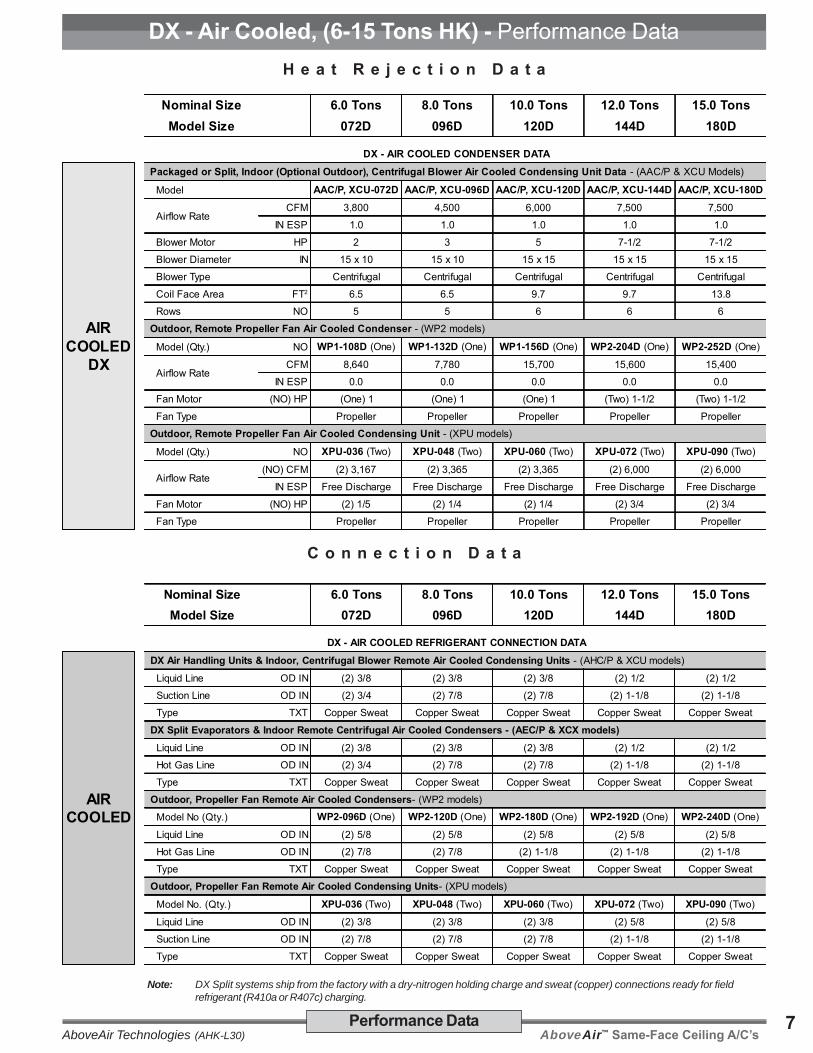
AboveAir™ Same-Face Ceiling A/C’sAboveAir Technologies (AHK-L30)7Performance Data
H e a t R e j e c t i o n D a t a
C o n n e c t i o n D a t a
Nominal Size 6.0 Tons 8.0 Tons 10.0 Tons 12.0 Tons 15.0 TonsModel Size 072D 096D 120D 144D 180D
DX - AIR COOLED REFRIGERANT CONNECTION DATA
AIRCOOLED
DX Air Handling Units & Indoor, Centrifugal Blower Remote Air Cooled Condensing Units - (AHC/P & XCU models)
Liquid Line OD IN (2) 3/8 (2) 3/8 (2) 3/8 (2) 1/2 (2) 1/2
Suction Line OD IN (2) 3/4 (2) 7/8 (2) 7/8 (2) 1-1/8 (2) 1-1/8
Type TXT Copper Sweat Copper Sweat Copper Sweat Copper Sweat Copper Sweat
DX Split Evaporators & Indoor Remote Centrifugal Air Cooled Condensers - (AEC/P & XCX models) Liquid Line OD IN (2) 3/8 (2) 3/8 (2) 3/8 (2) 1/2 (2) 1/2
Hot Gas Line OD IN (2) 3/4 (2) 7/8 (2) 7/8 (2) 1-1/8 (2) 1-1/8
Type TXT Copper Sweat Copper Sweat Copper Sweat Copper Sweat Copper Sweat
Outdoor, Propeller Fan Remote Air Cooled Condensers- (WP2 models)
Model No (Qty.) WP2-096D (One) WP2-120D (One) WP2-180D (One) WP2-192D (One) WP2-240D (One)
Liquid Line OD IN (2) 5/8 (2) 5/8 (2) 5/8 (2) 5/8 (2) 5/8
Hot Gas Line OD IN (2) 7/8 (2) 7/8 (2) 1-1/8 (2) 1-1/8 (2) 1-1/8
Type TXT Copper Sweat Copper Sweat Copper Sweat Copper Sweat Copper Sweat
Outdoor, Propeller Fan Remote Air Cooled Condensing Units- (XPU models)
Model No. (Qty.) XPU-036 (Two) XPU-048 (Two) XPU-060 (Two) XPU-072 (Two) XPU-090 (Two)
Liquid Line OD IN (2) 3/8 (2) 3/8 (2) 3/8 (2) 5/8 (2) 5/8
Suction Line OD IN (2) 7/8 (2) 7/8 (2) 7/8 (2) 1-1/8 (2) 1-1/8
Type TXT Copper Sweat Copper Sweat Copper Sweat Copper Sweat Copper Sweat
Note: DX Split systems ship from the factory with a dry-nitrogen holding charge and sweat (copper) connections ready for fieldrefrigerant (R410a or R407c) charging.
DX - Air Cooled, (6-15 Tons HK) - Performance Data
Nominal Size 6.0 Tons 8.0 Tons 10.0 Tons 12.0 Tons 15.0 TonsModel Size 072D 096D 120D 144D 180D
DX - AIR COOLED CONDENSER DATA
AIRCOOLED
DX
Packaged or Split, Indoor (Optional Outdoor), Centrifugal Blower Air Cooled Condensing Unit Data - (AAC/P & XCU Models)
Model AAC/P, XCU-072D AAC/P, XCU-096D AAC/P, XCU-120D AAC/P, XCU-144D AAC/P, XCU-180D
Airflow RateCFM 3,800 4,500 6,000 7,500 7,500
IN ESP 1.0 1.0 1.0 1.0 1.0 Blower Motor HP 2 3 5 7-1/2 7-1/2 Blower Diameter IN 15 x 10 15 x 10 15 x 15 15 x 15 15 x 15 Blower Type Centrifugal Centrifugal Centrifugal Centrifugal Centrifugal Coil Face Area FT2 6.5 6.5 9.7 9.7 13.8 Rows NO 5 5 6 6 6 Outdoor, Remote Propeller Fan Air Cooled Condenser - (WP2 models)
Model (Qty.) NO WP1-108D (One) WP1-132D (One) WP1-156D (One) WP2-204D (One) WP2-252D (One)
Airflow RateCFM 8,640 7,780 15,700 15,600 15,400
IN ESP 0.0 0.0 0.0 0.0 0.0 Fan Motor (NO) HP (One) 1 (One) 1 (One) 1 (Two) 1-1/2 (Two) 1-1/2 Fan Type Propeller Propeller Propeller Propeller Propeller Outdoor, Remote Propeller Fan Air Cooled Condensing Unit - (XPU models)
Model (Qty.) NO XPU-036 (Two) XPU-048 (Two) XPU-060 (Two) XPU-072 (Two) XPU-090 (Two)
Airflow Rate(NO) CFM (2) 3,167 (2) 3,365 (2) 3,365 (2) 6,000 (2) 6,000
IN ESP Free Discharge Free Discharge Free Discharge Free Discharge Free Discharge Fan Motor (NO) HP (2) 1/5 (2) 1/4 (2) 1/4 (2) 3/4 (2) 3/4 Fan Type Propeller Propeller Propeller Propeller Propeller

AboveAir™ Same-Face Ceiling A/C’s AboveAir Technologies (AHK-L30)8 Performance Data
Nominal Size 1.0 Ton 1.5 Tons 2.0 Tons 3.0 Tons 4.0 Tons 5.0 Tons
ComfortCoolTM Model AWC-012 AWC-018 AWC-024 AWC-036 AWC-048 AWC-060
WATERCOOLED
DX
STDCFM
80°F DB / 67°F WB, 50% RH Total BTUH 15,400 21,000 29,500 43,300 56,900 71,700
Sensible BTUH 10,700 15,000 21,200 31,200 41,400 51,900
75°F DB / 62.5°F WB, 50% RH Total BTUH 14,200 19,300 27,100 39,800 52,400 66,300
Sensible BTUH 10,500 14,700 20,800 30,700 40,700 51,300
72°F DB / 60°F WB, 50% RH Total BTUH 13,500 18,400 25,900 38,000 50,000 63,400
Sensible BTUH 10,300 14,400 20,400 30,100 39,900 50,300
PrecisionCoolTM Model AWP-012 AWP-018 AWP-024 AWP-036 AWP-048 AWP-060
WATERCOOLED
DX
OPTCFM
80°F DB / 67°F WB, 50% RH Total BTUH 16,000 21,700 30,500 44,800 60,100 74,100
Sensible BTUH 11,800 16,600 23,700 34,700 50,000 57,900
75°F DB / 62.5°F WB, 50% RH Total BTUH 14,600 19,900 28,200 41,100 55,500 68,500
Sensible BTUH 11,500 16,200 23,600 34,200 49,300 57,20072°F DB / 60°F WB, 50% RH Total BTUH 13,900 18,900 27,000 39,600 53,000 65,900
Sensible BTUH 11,400 16,000 23,200 34,000 48,300 56,900
GENERAL SHARED DATA
WATERCOOLED
DX
Electric Heat and/or Reheat (Factory Installed) - BTUH include standard evaporator motor heat, (Optional) Capacity BTUH (KW) 17,675 (5.2) 17,675 (5.2) 18,245 (5.3) 36,490 (10.7) 36,490 (10.7) 37,635 (11.0)
Stages NO 1 1 1 1 1 1
Hot Water & Steam Heating - (Optional) Capacity See Page 13 for Complete Hot Water & Steam Heating Coil Performance Data
Steam Canister Humidifier - (Optional) Steam Capacity LBS/HR 5 5 5 5 10 10
Power Input KW 1.79 1.79 1.79 1.79 3.4 3.4
Evaporator Blower / Motor - Belt Drive, DWDI Centrifugal
Std Airflow Rate CFM 400 600 800 1,200 1,600 2,000
Std Blower Motor HP 1/3 1/3 1/2 3/4 3/4 1
Opt Airflow Rate CFM 500 750 1,000 1,500 2,250 2,500
Opt Blower Motor HP 1/3 1/3 1/2 3/4 1 1-1/2
E.S.P. IN WG 0.75 0.75 0.75 0.75 0.75 0.75 Blower Diameter IN 10 X 8 10 X 8 10 X 8 10 X 8 12 X 9 12 X 9
Evaporator Coil - Aluminum Fin, Copper Tube
Rows NO 3 3 4 4 4 4
Face Area FT2 2.0 2.0 2.9 2.9 5.1 5.1
Filters - 30% Dust Spot Efficient
(Qty.) Nom. Size (NO) IN (1) 18 x 24 x 2 (1) 18 x 24 x 2 (1) 18 x 24 x 2 (1) 18 x 24 x 2 (2) 16 x 24 x 2 (2) 16 x 24 x 2 Compressor - Heat Pump Duty Hermetic
Type TXT Scroll Scroll Scroll Scroll Scroll Scroll
(Qty.) Horsepower (NO) HP (1) 1.0 (1) 1.5 (1) 2.0 (1) 3.0 (1) 4.0 (1) 5.0
Water Cooled Condenser Data - 85°F EWT / 95°F LWT, 0% glycol solution (rated at 80°F DB/67°F WB EAT, Opt Evap CFM)
Total Heat of Rej. BTUH 19,045 25,900 35,900 52,855 71,100 88,150
Flow Rate GPM 3.8 5.2 7.2 10.6 14.2 17.6
Water Press Drop FT WG 11.3 12.2 15.0 20.0 18.4 29.9 Condenser Type TXT Coaxial Coaxial Coaxial Coaxial Coaxial Coaxial
Water Reg. Valve 2-Way, 150 psig - factory installed, (3-way & High Pressure Valves are Optional)
Connection Data Water IN/OUT IN OD 5/8 5/8 7/8 7/8 1-1/8 1-1/8
Condensate Drain FPT IN 3/4 3/4 3/4 3/4 3/4 3/4
Humidifier Inlet IN OD 1/4 1/4 1/4 1/4 1/4 1/4
DX - Water Cooled, (1-5 Tons HK) - Performance Data
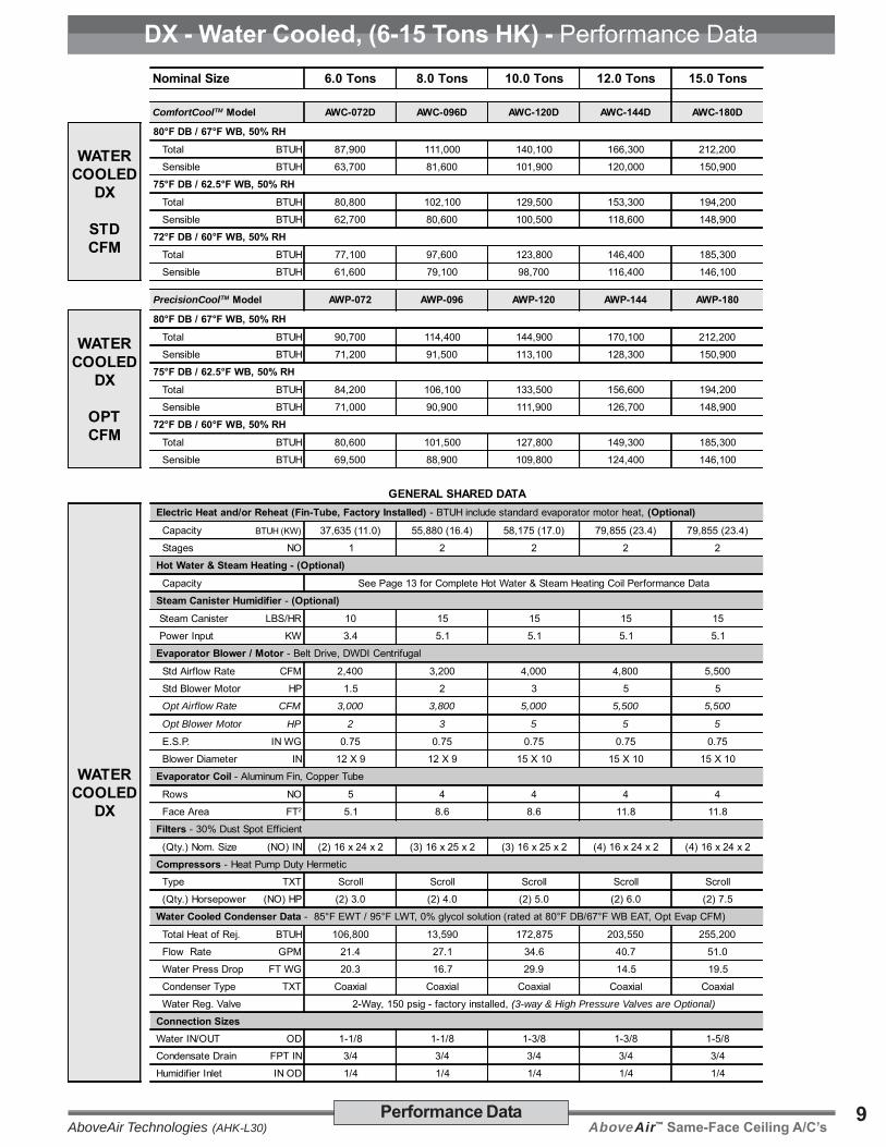
AboveAir™ Same-Face Ceiling A/C’sAboveAir Technologies (AHK-L30)9Performance Data
Nominal Size 6.0 Tons 8.0 Tons 10.0 Tons 12.0 Tons 15.0 Tons
ComfortCoolTM Model AWC-072D AWC-096D AWC-120D AWC-144D AWC-180D
WATERCOOLED
DX
STDCFM
80°F DB / 67°F WB, 50% RH Total BTUH 87,900 111,000 140,100 166,300 212,200
Sensible BTUH 63,700 81,600 101,900 120,000 150,900
75°F DB / 62.5°F WB, 50% RH Total BTUH 80,800 102,100 129,500 153,300 194,200
Sensible BTUH 62,700 80,600 100,500 118,600 148,900
72°F DB / 60°F WB, 50% RH Total BTUH 77,100 97,600 123,800 146,400 185,300
Sensible BTUH 61,600 79,100 98,700 116,400 146,100
PrecisionCoolTM Model AWP-072 AWP-096 AWP-120 AWP-144 AWP-180
WATERCOOLED
DX
OPTCFM
80°F DB / 67°F WB, 50% RH Total BTUH 90,700 114,400 144,900 170,100 212,200
Sensible BTUH 71,200 91,500 113,100 128,300 150,900
75°F DB / 62.5°F WB, 50% RH Total BTUH 84,200 106,100 133,500 156,600 194,200
Sensible BTUH 71,000 90,900 111,900 126,700 148,900
72°F DB / 60°F WB, 50% RH Total BTUH 80,600 101,500 127,800 149,300 185,300
Sensible BTUH 69,500 88,900 109,800 124,400 146,100
GENERAL SHARED DATA
WATERCOOLED
DX
Electric Heat and/or Reheat (Fin-Tube, Factory Installed) - BTUH include standard evaporator motor heat, (Optional) Capacity BTUH (KW) 37,635 (11.0) 55,880 (16.4) 58,175 (17.0) 79,855 (23.4) 79,855 (23.4)
Stages NO 1 2 2 2 2
Hot Water & Steam Heating - (Optional) Capacity See Page 13 for Complete Hot Water & Steam Heating Coil Performance Data
Steam Canister Humidifier - (Optional) Steam Canister LBS/HR 10 15 15 15 15
Power Input KW 3.4 5.1 5.1 5.1 5.1
Evaporator Blower / Motor - Belt Drive, DWDI Centrifugal
Std Airflow Rate CFM 2,400 3,200 4,000 4,800 5,500
Std Blower Motor HP 1.5 2 3 5 5
Opt Airflow Rate CFM 3,000 3,800 5,000 5,500 5,500
Opt Blower Motor HP 2 3 5 5 5
E.S.P. IN WG 0.75 0.75 0.75 0.75 0.75
Blower Diameter IN 12 X 9 12 X 9 15 X 10 15 X 10 15 X 10
Evaporator Coil - Aluminum Fin, Copper Tube
Rows NO 5 4 4 4 4
Face Area FT2 5.1 8.6 8.6 11.8 11.8
Filters - 30% Dust Spot Efficient
(Qty.) Nom. Size (NO) IN (2) 16 x 24 x 2 (3) 16 x 25 x 2 (3) 16 x 25 x 2 (4) 16 x 24 x 2 (4) 16 x 24 x 2
Compressors - Heat Pump Duty Hermetic
Type TXT Scroll Scroll Scroll Scroll Scroll
(Qty.) Horsepower (NO) HP (2) 3.0 (2) 4.0 (2) 5.0 (2) 6.0 (2) 7.5
Water Cooled Condenser Data - 85°F EWT / 95°F LWT, 0% glycol solution (rated at 80°F DB/67°F WB EAT, Opt Evap CFM)
Total Heat of Rej. BTUH 106,800 13,590 172,875 203,550 255,200
Flow Rate GPM 21.4 27.1 34.6 40.7 51.0
Water Press Drop FT WG 20.3 16.7 29.9 14.5 19.5
Condenser Type TXT Coaxial Coaxial Coaxial Coaxial Coaxial
Water Reg. Valve 2-Way, 150 psig - factory installed, (3-way & High Pressure Valves are Optional)
Connection Sizes Water IN/OUT OD 1-1/8 1-1/8 1-3/8 1-3/8 1-5/8 Condensate Drain FPT IN 3/4 3/4 3/4 3/4 3/4
Humidifier Inlet IN OD 1/4 1/4 1/4 1/4 1/4
DX - Water Cooled, (6-15 Tons HK) - Performance Data

AboveAir™ Same-Face Ceiling A/C’s AboveAir Technologies (AHK-L30)10 Performance Data
Nominal Size 1.0 Ton 1.5 Tons 2.0 Tons 3.0 Tons 4.0 Tons 5.0 Tons
ComfortCoolTM Model AGC-012 AGC-018 AGC-024 AGC-036 AGC-048 AGC-060
GLYCOLCOOLED
DX
STDCFM
80°F DB / 67°F WB, 50% RH Total BTUH 14,200 19,400 27,200 39,800 52,600 66,200
Sensible BTUH 10,100 14,300 20,100 29,700 39,500 49,500
75°F DB / 62.5°F WB, 50% RH Total BTUH 13,000 17,800 24,900 36,600 48,200 60,800
Sensible BTUH 9,900 14,000 19,800 29,100 38,900 48,600
72°F DB / 60°F WB, 50% RH Total BTUH 12,400 17,000 23,900 34,800 46,200 57,800
Sensible BTUH 9,700 13,700 19,700 28,600 38,600 47,700
PrecisionCoolTM Model AGP-012 AGP-018 AGP-024 AGP-036 AGP-048 AGP-060
GLYCOLCOOLED
DX
OPTCFM
80°F DB / 67°F WB, 50% RH Total BTUH 14,700 20,000 28,200 41,000 55,400 68,200
Sensible BTUH 11,200 15,800 22,900 33,200 48,200 55,400
75°F DB / 62.5°F WB, 50% RH Total BTUH 13,600 18,600 25,900 38,000 51,100 63,200
Sensible BTUH 11,300 16,000 22,700 33,100 47,500 55,10072°F DB / 60°F WB, 50% RH Total BTUH 12,900 17,700 24,700 36,300 48,800 60,300
Sensible BTUH 11,100 15,600 22,300 32,400 46,500 54,000
GENERAL SHARED DATA
GLYCOLCOOLED
DX
Electric Heat and/or Reheat (Fin-Tube, Factory Installed) - BTUH include standard evaporator motor heat, (Optional) Capacity BTUH (KW) 17,675 (5.2) 17,675 (5.2) 18,245 (5.3) 36,490 (10.7) 36,490 (10.7) 37,635 (11.0)
Stages NO 1 1 1 1 1 1
Hot Water & Steam Heating - (Optional) Capacity See Page 13 for Complete Hot Water & Steam Heating Coil Performance Data
Steam Canister Humidifier - (Optional) Steam Capacity LBS/HR 5 5 5 5 10 10
Power Input KW 1.79 1.79 1.79 1.79 3.4 3.4
Evaporator Blower / Motor - Belt Drive, DWDI Centrifugal
Std Airflow Rate CFM 400 600 800 1,200 1,600 2,000
Std Blower Motor HP 1/3 1/3 1/2 3/4 3/4 1
Opt Airflow Rate CFM 500 750 1,000 1,500 2,250 2,500
Opt Blower Motor HP 1/3 1/3 1/2 3/4 1 1-1/2
E.S.P. IN WG 0.75 0.75 0.75 0.75 0.75 0.75 Blower Diameter IN 10 X 8 10 X 8 10 X 8 10 X 8 12 X 9 12 X 9
Evaporator Coil - Aluminum Fin, Copper Tube
Rows NO 3 3 4 4 4 4
Face Area FT2 2.0 2.0 2.9 2.9 5.1 5.1
Filters - 30% Dust Spot Efficient
(Qty.) Nom. Size (NO) IN (1) 18 x 24 x 2 (1) 18 x 24 x 2 (1) 18 x 24 x 2 (1) 18 x 24 x 2 (2) 16 x 24 x 2 (2) 16 x 24 x 2 Compressor - Heat Pump Duty Hermetic
Type TXT Scroll Scroll Scroll Scroll Scroll Scroll
(Qty.) Horsepower (NO) HP (1) 1.0 (1) 1.5 (1) 2.0 (1) 3.0 (1) 4.0 (1) 5.0
Glycol Cooled Condenser Data - 110°F EGT / 120°F LGT, 40% Ethylene Glycol solution (rated at 80°F DB/67°F WB EAT, Opt Evap CFM)
Total Heat of Rej. BTUH 18,690 25,510 35,120 51,410 69,310 85,470
Flow Rate GPM 4.1 5.6 7.8 14.4 15.4 18.9
Glycol Press Drop FT WG 10.8 11.8 14.3 18.9 17.7 28.4 Condenser Type TXT Coaxial Coaxial Coaxial Coaxial Coaxial Coaxial
Glycol Reg. Valve 2-Way, 150 psig - factory installed, (3-way & High Pressure Valves are Optional)
Connection Data Glycol IN/OUT OD 5/8 5/8 7/8 7/8 1-1/8 1-1/8
Condensate Drain FPT IN 3/4 3/4 3/4 3/4 3/4 3/4
Humidifier Inlet IN OD 1/4 1/4 1/4 1/4 1/4 1/4
DX - Glycol Cooled, (1-5 Tons HK) - Performance Data

AboveAir™ Same-Face Ceiling A/C’sAboveAir Technologies (AHK-L30)11Performance Data
Nominal Size 6.0 Tons 8.0 Tons 10.0 Tons 12.0 Tons 15.0 Tons
ComfortCoolTM Model AGC-072D AGC-096D AGC-120D AGC-144D AGC-180D
GLYCOLCOOLED
DX
STDCFM
80°F DB / 67°F WB, 50% RH Total BTUH 80,900 102,400 129,200 153,100 189,500
Sensible BTUH 60,800 78,200 97,200 114,700 141,900
75°F DB / 62.5°F WB, 50% RH Total BTUH 74,600 94,200 118,600 140,300 173,500
Sensible BTUH 60,400 76,900 95,400 112,400 139,100
72°F DB / 60°F WB, 50% RH Total BTUH 71,200 89,900 112,900 133,800 165,200
Sensible BTUH 59,200 75,300 93,700 110,400 136,100
PrecisionCoolTM Model AGP-072 AGP-096 AGP-120 AGP-144 AGP-180
GLYCOLCOOLED
DX
OPTCFM
80°F DB / 67°F WB, 50% RH Total BTUH 83,900 106,100 133,000 156,200 189,500
Sensible BTUH 68,800 88,600 108,700 122,800 141,900
75°F DB / 62.5°F WB, 50% RH Total BTUH 77,300 97,700 122,800 142,900 173,500
Sensible BTUH 67,700 86,700 108,100 120,600 139,100
72°F DB / 60°F WB, 50% RH Total BTUH 73,900 93,100 117,000 136,200 165,200
Sensible BTUH 66,400 84,800 105,900 118,200 136,100
GENERAL SHARED DATA
GLYCOLCOOLED
DX
Electric Heat and/or Reheat (Fin-Tube, Factory Installed) - BTUH include standard evaporator motor heat, (Optional) Capacity BTUH (KW) 37,635 (11.0) 55,880 (16.4) 58,175 (17.0) 79,855 (23.4) 79,855 (23.4)
Stages NO 1 2 2 2 2
Hot Water & Steam Heating - (Optional) Capacity See Page 13 for Complete Hot Water & Steam Heating Coil Performance Data
Steam Canister Humidifier - (Optional) Steam Canister LBS/HR 10 15 15 15 15
Power Input KW 3.4 5.1 5.1 5.1 5.1
Evaporator Blower / Motor - Belt Drive, DWDI Centrifugal
Std Airflow Rate CFM 2,400 3,200 4,000 4,800 5,500
Std Blower Motor HP 1.5 2 3 5 5
Opt Airflow Rate CFM 3,000 3,800 5,000 5,500 5,500
Opt Blower Motor HP 2 3 5 5 5
E.S.P. IN WG 0.75 0.75 0.75 0.75 0.75
Blower Diameter IN 12 X 9 12 X 9 15 X 10 15 X 10 15 X 10
Evaporator Coil - Aluminum Fin, Copper Tube
Rows NO 5 4 4 4 4
Face Area FT2 5.1 8.6 8.6 11.8 11.8
Filters - 30% Dust Spot Efficient
(Qty.) Nom. Size (NO) IN (2) 16 x 24 x 2 (3) 16 x 25 x 2 (3) 16 x 25 x 2 (4) 16 x 24 x 2 (4) 16 x 24 x 2
Compressors - Heat Pump Duty Hermetic
Type TXT Scroll Scroll Scroll Scroll Scroll
(Qty.) Horsepower (NO) HP (2) 3.0 (2) 4.0 (2) 5.0 (2) 6.2 (2) 7.5
Glycol Cooled Condenser Data - 110°F EGT/120°F LGT, 40% EG solution (rated at 80°F DB/67°F WB EAT, Opt Evap CFM)
Total Heat of Rej. BTUH 104,590 132,550 167,550 198,740 247,500
Flow Rate GPM 23.1 29.3 37.1 44.0 54.8
Glycol Press Drop FT WG 19.4 16.0 27.4 13.6 18.3
Condenser Type TXT Coaxial Coaxial Coaxial Coaxial Coaxial Glycol Reg. Valve 2-Way, 150 psig - factory installed, (3-way & High Pressure Valves are Optional)
Connection Sizes Glycol IN/OUT IN OD 1-1/8 1-1/8 1-3/8 1-3/8 1-5/8
Condensate Drain FPT IN 3/4 3/4 3/4 3/4 3/4
Humidifier Inlet IN OD 1/4 1/4 1/4 1/4 1/4
DX - Glycol Cooled, (6-15 Tons HK) - Performance Data

AboveAir™ Same-Face Ceiling A/C’s AboveAir Technologies (AHK-L30)12 Performance Data
Nominal Unit Size 1.0 Ton 1.5 Tons 2.0 Tons 3.0 Tons 4.0 Tons 5.0 Tons 6.0 Tons 8.0 Tons 10.0 Tons 12.0 Tons 15.0 Tons
Cooling Capacity - BTUH @ 45°F EWT, 0% Glycol Solution
STD CFM, ComfortCoolTM ACC-012 ACC-018 ACC-024 ACC-036 ACC-048 ACC-060 ACC-072 ACC-096 ACC-120 ACC-144 ACC-180 80°F DB / 67°F WB, 50% RH Total BTUH 13,300 18,300 29,800 40,300 58,600 69,100 91,700 111,500 127,500 149,600 211,300
Sensible BTUH 9,600 13,500 20,800 29,000 41,000 49,200 63,500 79,600 93,600 110,100 146,800
75°F DB / 62.5°F WB, 50% RH Total BTUH 10,500 14,500 23,400 31,800 46,000 54,400 72,000 88,200 101,300 118,800 166,500
Sensible BTUH 8,800 12,400 18,900 26,500 37,300 45,000 57,600 72,900 86,200 101,400 133,500
72°F DB / 60°F WB, 50% RH Total BTUH 9,100 12,600 20,100 27,500 39,500 46,900 61,800 76,200 87,800 103,000 143,300
Sensible BTUH 8,200 11,700 17,600 24,800 34,800 42,100 53,700 68,200 81,000 95,300 124,500
Flow Rate GPM 2.5 3.5 6.0 8.0 12.0 14.0 18.0 22.5 24.0 30.0 40.0
Coil Press. Drop FT H2O 1.9 3.4 3.4 5.6 3.4 4.4 8.7 12.8 4.4 6.5 17.4
OPT CFM, PrecisionCoolTM ACP-012 ACP-018 ACP-024 ACP-036 ACP-048 ACP-060 ACP-072 ACP-096 ACP-120 ACP-144 ACP-180 80°F DB / 67°F WB, 50% RH Total BTUH 15,900 21,300 35,200 47,100 74,800 80,100 106,400 120,400 151,900 166,600 211,300
Sensible BTUH 11,600 16,000 25,000 34,600 54,000 58,500 75,600 89,200 112,900 123,400 146,800
75°F DB / 62.5°F WB, 50% RH Total BTUH 12,600 17,000 27,700 37,400 59,100 63,500 84,100 96,400 121,000 132,500 166,500
Sensible BTUH 10,600 14,800 22,800 31,900 49,500 53,800 69,100 82,600 104,300 113,900 133,500
72°F DB / 60°F WB, 50% RH Total BTUH 10,900 14,700 23,900 32,400 51,000 55,000 72,500 84,100 105,200 115,200 143,300
Sensible BTUH 10,000 14,000 21,300 29,900 46,300 50,500 64,600 77,800 98,200 107,200 124,500
Flow Rate GPM 3.0 4 7 9.5 15.0 16.0 21.0 24.0 30.0 36.0 40.0
Coil Press. Drop FT H2O 2.6 4.3 4.4 7.6 5.0 5.6 11.3 14.3 6.5 8.9 17.4
Chilled Water Coil / Valve - Aluminum Fin, Copper Tube
Rows NO 3 3 4 4 4 4 4 4 4 4 6
Face Area FT2 2.0 2.0 2.8 2.8 4.9 4.9 4.9 8.6 8.6 11.8 11.8
Standard Valve BTUH 2-way, 300 psig - field installed (3-way Valves are Optional)
GENERAL SHARED DATA Electric Heat and/or Reheat (Factory Installed) - includes standard evaporator motor heat, (Optional)
CapacityBTUH 17,675 17,675 18,245 36,490 36,490 37,635 37,635 55,880 58,175 79,855 79,855
KW 5.2 5.2 5.3 10.7 10.7 11.0 11.0 16.4 17.0 23.4 23.4
Stages NO 1 1 1 1 1 1 1 2 2 2 2
Type TXT Fin-Tube Fin-Tube Fin-Tube Fin-Tube Fin-Tube Fin-Tube Fin-Tube Fin-Tube Fin-Tube Fin-Tube Fin-Tube
Hot Water & Steam Heating - (Optional) Capacity See Page 13 for Complete Hot Water & Steam Heating Coil Performance Data
Steam Canister Humidifier - (Optional) Steam Canister LBS/HR 5 5 5 5 10 10 10 15 15 15 15
Power Input KW 1.79 1.79 1.79 1.79 3.4 3.4 3.4 5.1 5.1 5.1 5.1
Evaporator Blower / Motor - Belt Drive, DWDI Centrifugal
Std Airflow Rate CFM 400 600 900 1,200 1,600 2,000 2,400 3,200 4,000 4,800 5,500
Std Blower Motor HP 1/2 1/2 1/2 3/4 3/4 1 1-1/2 2 3 5 5
Opt Airflow Rate CFM 500 750 1,000 1,500 2,250 2,500 3,000 3,800 5,000 5,500 5,500
Opt Blower Motor HP 1/2 1/2 1/2 3/4 1 1-1/2 2 3 5 5 5
E.S.P. IN WG 0.75 0.75 0.75 0.75 0.75 0.75 0.75 0.75 0.75 0.75 0.75
Fan Diameter IN 10 X 8 10 X 8 10 X 8 10 X 8 12 X 9 12 X 9 12 X 9 12 X 9 15 X 10 15 X 10 15 X 10
Filters - 2", 30% Dust Spot Efficient
(Qty.) Nom. Size (NO) IN (1) 18x24 (1) 18x24 (1) 18x24 (1) 18x24 (2) 16x24 (2) 16x24 (2) 16x24 (3) 16x25 (3) 16x25 (4) 16x24 (4) 16x24
Connection Sizes - Copper
Chilled Water IN OD 5/8 5/8 7/8 7/8 1-1/8 1-1/8 1-1/8 1-3/8 1-3/8 1-5/8 1-5/8
Condensate Drain FPT IN 3/4 3/4 3/4 3/4 3/4 3/4 3/4 3/4 3/4 3/4 3/4
Humidifier Inlet IN OD 1/4 1/4 1/4 1/4 1/4 1/4 1/4 1/4 1/4 1/4 1/4
Chilled Water Systems, (1-15 Tons HK) - Performance Data

AboveAir™ Same-Face Ceiling A/C’sAboveAir Technologies (AHK-L30)13Performance Data
HOT WATER HEATING COIL Nominal Unit Size 1.0 Ton 1.5 Tons 2.0 Tons 3.0 Tons 4.0 Tons 5.0 Tons 6.0 Tons 8.0 Tons 10.0 Tons 12.0 Tons 15.0 Tons
Hot Water Heating Coil - @ 180°F EWT / 160 LWT, 70°F EAT, (Optional)
ComfortCoolTM Model A_C-012 A_C-018 A_C-024 A_C-036 A_C-048 A_C-060 A_C-072 A_C-096 A_C-120 A_C-144 A_C-180
Std Airflow Rate CFM 400 600 900 1,200 1,600 2,000 2,400 3,200 4,000 4,800 5,500
Heating Capacity BTUH 19,310 25,250 36,060 46,290 67,750 78,440 87,510 102,290 150,950 167,280 180,750
Flow Rate GPM 1.8 2.4 3.5 4.5 6.6 7.6 8.5 10.1 16.0 17.3 18.7
Fluid Press. Drop FT H2O 1.7 2.8 2.5 3.8 2.8 3.6 4.3 5.8 4.0 4.5 5.2
LAT °F DB 108.2 103.4 107.4 102.2 105.6 102.8 100.6 97.2 103.9 101.3 99.5
PrecisionCoolTM Model A_P-012 A_P-018 A_P-024 A_P-036 A_P-048 A_P-060 A_P-072 A_P-096 A_P-120 A_P-144 A_P-180
Opt Airflow Rate CFM 500 750 1,000 1,500 2,250 2,500 3,000 3,800 5,000 5,500 5,500
Heating Capacity BTUH 22,470 28,810 41,680 52,850 83,570 89,580 98,620 112,480 171,650 180,750 180,750
Flow Rate GPM 2.1 2.7 4.0 5.1 8.1 8.7 9.7 11.2 18.0 18.7 18.7
Fluid Press. Drop FT H2O 2.2 3.4 3.1 4.8 4.0 4.5 5.4 7.0 4.9 5.2 5.2
LAT °F DB 105.5 100.7 104.5 99.5 101.3 100.1 97.9 95.3 100.8 99.5 99.5
Hot Water Heating Coil Physical Data Rows NO 1 1 1 1 1 1 1 1 1 1 1
Face Area FT2 2.0 2.0 2.8 2.8 4.9 4.9 4.9 8.6 8.6 11.8 11.8
HW IN/OUT IN OD 5/8 5/8 5/8 5/8 7/8 7/8 7/8 1-1/8 1-1/8 1-1/8 1-1/8
Standard Valve TXT 2-way - field installed (3-way valves are optional)
STEAM HEATING COIL Nominal Unit Size 1.0 Ton 1.5 Tons 2.0 Tons 3.0 Tons 4.0 Tons 5.0 Tons 6.0 Tons 8.0 Tons 10.0 Tons 12.0 Tons 15.0 Tons
Steam Heating Coil - @ 5 PSIG (227.1°F) Supply Steam, 70°F EAT, (Optional)
ComfortCoolTM Model A_C-012 A_C-018 A_C-024 A_C-036 A_C-048 A_C-060 A_C-072 A_C-096 A_C-120 A_C-144 A_C-180
Std Airflow Rate CFM 400 600 800 1,200 1,600 2,000 2,400 3,200 4,000 4,800 5,500
Heating Capacity BTUH 29,840 37,760 53,360 66,700 100,300 113,230 124,450 143,250 213,640 234,270 250,280
Condensate LB/HR 31 39 56 69 104 118 130 149 223 244 113
Steam Pr. Drop FT H2O 0.1 0.1 0.1 0.1 0.1 0.1 0.1 0.1 0.1 0.1 0.1
LAT °F DB 139.8 128.9 132.4 122.0 128.6 122.9 118.5 111.9 119.9 115.6 112.6
PrecisionCoolTM Model A_P-012 A_P-018 A_P-024 A_P-036 A_P-048 A_P-060 A_P-072 A_P-096 A_P-120 A_P-144 A_P-180
Opt Airflow Rate CFM 500 750 1,000 1,500 2,250 2,500 3,000 3,800 5,000 5,500 5,500
Heating Capacity BTUH 34,050 42,620 60,480 74,770 120,410 127,040 138,920 155,030 239,020 250,280 250,280
Condensate LB/HR 35 44 63 78 125 132 145 162 249 113 113
Steam Pr. Drop FT H2O 0.1 0.1 0.1 0.1 0.1 0.1 0.1 0.1 0.1 0.1 0.1
LAT °F DB 133.7 123.1 126.6 116.6 120.0 117.5 113.3 108.2 114.7 112.6 112.6
Steam Heating Coil Physical Data Rows NO 1 1 1 1 1 1 1 1 1 1 1
Face Area FT2 2.0 2.0 2.8 2.8 4.9 4.9 4.9 8.6 8.6 11.8 11.8
STM IN/OUT IN OD 5/8 5/8 5/8 5/8 7/8 7/8 7/8 1-1/8 1-1/8 1-1/8 1-1/8
Standard Valve TXT 2-way - field installed (3-way valves are optional) - Steam Specialties by Others
Hot Water & Steam Heating Coils, (HK) - Performance Data

AboveAir™ Same-Face Ceiling A/C’s AboveAir Technologies (AHK-L30)14 Electrical Data
Electrical Data (Standard CFM) - Air Cooled, Self-Contained
LEDOM _-210-CAA _-810-CAA _-420-CAA _-630-CAA
ylppuSrewoP 06/1/802 06/1/772 06/3/802 06/3/064 06/1/802 06/1/772 06/3/802 06/3/064 06/1/802 06/1/772 06/3/802 06/3/064 06/1/802 06/1/772 06/3/802 06/3/064
ylnOgnilooC )taeHmaetSroretaWtoHhtiwgnilooCro(
ALF 0.81 6.41
---- ----
7.81 6.41
---- ----
6.22 2.71 3.41 2.7 1.03 2.52 6.81 .9
ACM 5.02 8.61 4.12 8.61 0.62 8.91 5.61 2.8 7.43 3.92 5.12 7.01
POM 03 52 03 52 53 03 52 51 05 54 03 51
taeHcirtcelEhtiw )reifidimuHrotaeheRcirtcelEoN(
ALF 1.82 1.12
---- ----
1.82 1.12
---- ----
1.82 1.12 2.61 4.7 2.35 9.93 2.13 3.41
ACM 1.53 4.62 1.53 4.62 1.53 4.62 3.02 3.9 5.66 9.94 0.93 8.71
POM 04 03 04 03 04 03 52 51 07 05 04 02
taeH/taeheRcirtcelEhtiw )reifidimuHoN(
ALF 1.24 7.23
---- ----
8.24 7.23
---- ----
7.64 2.53 2.82 4.31 3.87 4.16 4.64 9.12
ACM 6.05 4.93 5.15 4.63 1.65 4.24 8.33 1.61 9.49 5.47 2.65 4.62
POM 06 04 06 04 06 54 53 02 001 08 06 03
taeHmaetS/retaWtoHtuohtiwrohtiwreifidimuHhtiw )taeH/taeheRcirtcelEoN(
ALF 2.62 8.02
---- ----
9.62 8.02
---- ----
8.03 4.32 5.22 9.01 3.83 4.13 8.62 0.31
ACM 7.82 0.32 6.92 0.32 2.43 0.62 7.42 9.11 9.24 5.53 7.92 4.41
POM 53 03 04 03 54 53 03 51 06 05 04 02
taeHcirtcelEhtiw )taeheRcirtcelEoN( reifidimuH&
ALF 3.63 3.72
---- ----
3.63 3.72
---- ----
3.63 3.72 4.42 1.11 4.16 1.64 4.93 0.81
ACM 3.34 6.23 3.34 6.23 3.34 6.23 5.82 0.31 7.47 1.65 2.74 5.12
POM 54 53 54 53 54 53 03 51 08 06 05 52
reifidimuH&taeH/taeheRcirtcelEhtiw
ALF 1.24 7.23
---- ----
8.24 7.23
---- ----
7.64 2.53 2.82 4.31 3.87 4.16 4.64 9.12
ACM 6.05 4.93 5.15 4.93 1.65 4.24 8.33 1.61 9.49 5.47 2.65 4.62
POM 06 04 06 04 06 54 53 02 001 08 06 03
LEDOM _-840-CAA _060-CAA _-270-CAA _-690-CAA _-021-CAA _-441-CAA _-081-CAA
ylppuSrewoP 06/3/802 06/3/064 06/3/802 06/3/064 06/3/802 06/3/064 06/3/802 06/3/064 06/3/802 06/3/064 06/3/802 06/3/064 06/3/802 06/3/064
ylnOgnilooC )taeHmaetSroretaWtoHhtiwgnilooCro(
ALF 6.32 5.11 0.92 1.41 3.33 5.61 0.74 6.22 1.36 5.03 6.76 6.03 8.67 4.53
ACM 7.72 4.31 2.43 6.61 2.63 9.71 1.15 6.42 3.86 0.33 7.27 8.23 0.38 2.83
POM 04 02 05 52 54 02 06 03 08 04 09 04 001 54
taeHcirtcelEhtiw )reifidimuHrotaeheRcirtcelEoN(
ALF 2.13 3.41 6.13 5.41 3.33 5.61 7.74 6.22 1.36 5.03 1.96 7.13 8.67 4.53
ACM 0.93 8.71 5.93 1.81 4.04 5.81 6.95 2.72 3.86 0.33 4.68 6.93 4.68 6.93
POM 04 02 05 52 54 02 06 03 08 04 09 04 001 54
taeH/taeheRcirtcelEhtiw )reifidimuHoN(
ALF 4.15 0.42 8.65 7.62 1.16 1.92 7.88 5.14 8.401 4.94 2.321 8.55 4.231 6.06
ACM 5.26 1.92 9.86 3.23 9.07 6.33 2.301 1.84 4.021 6.65 2.241 2.46 6.251 6.96
POM 07 03 08 53 08 53 011 05 521 06 051 07 571 07
taeHmaetS/retaWtoHtuohtiwrohtiwreifidimuHhtiw )taeH/taeheRcirtcelEoN(
ALF 0.04 9.81 4.54 5.12 5.74 9.22 2.16 0.92 3.77 9.63 8.18 0.73 0.19 8.14
ACM 1.44 8.02 6.05 0.42 4.05 3.42 3.56 0.13 5.28 4.93 9.68 2.93 2.79 6.44
POM 06 52 07 03 06 03 08 53 001 54 001 54 011 05
taeHcirtcelEhtiw )taeheRcirtcelEoN( reifidimuH&
ALF 6.74 7.12 0.84 9.12 5.74 9.22 9.16 0.92 3.77 9.63 3.38 1.83 0.19 8.14
ACM 4.55 2.52 9.55 5.52 6.45 9.42 8.37 6.33 5.28 4.93 6.001 0.64 6.001 0.64
POM 06 03 07 03 06 03 08 53 001 54 011 05 011 05
reifidimuH&taeH/taeheRcirtcelEhtiw
ALF 4.15 0.42 8.65 7.62 1.16 1.92 7.88 5.14 8.401 4.94 2.321 8.55 4.231 6.06
ACM 5.26 1.92 9.86 3.23 9.07 6.33 2.301 1.84 4.021 6.65 2.241 2.46 6.251 6.96
POM 07 03 08 53 08 53 011 05 521 06 051 07 571 07
STANDARD CFM, DX-Air Cooled Self-Contained, 1 to 3 Tons
STANDARD CFM, DX-Air Cooled Self-Contained, 6 to 15 Tons
Notes:1) FLA = Full Load Amps; MCA = Min Circuit Amps; MOP = Max Overcurrent Protection2) 277V available via field installed step-down transformer.

AboveAir™ Same-Face Ceiling A/C’sAboveAir Technologies (AHK-L30)15Electrical Data
Electrical Data (Optional CFM) - Air Cooled, Self-Contained
LEDOM _-210-PAA _-810-PAA _-420-PAA _-630-PAA
ylppuSrewoP 06/1/802 06/1/772 06/3/802 06/3/064 06/1/802 06/1/772 06/3/802 06/3/064 06/1/802 06/1/772 06/3/802 06/3/064 06/1/802 06/1/772 06/3/802 06/3/064
ylnOgnilooC )taeHmaetSroretaWtoHhtiwgnilooCro(
ALF 0.81 6.41
---- ----
7.81 6.41
---- ----
6.22 2.71 3.41 2.7 1.03 2.52 6.81 .9
ACM 5.02 8.61 4.12 8.61 0.62 8.91 5.61 2.8 7.43 3.92 5.12 7.01
POM 03 52 03 52 53 03 52 51 05 54 03 51
taeHcirtcelEhtiw )reifidimuHrotaeheRcirtcelEoN(
ALF 1.82 1.12
---- ----
1.82 1.12
---- ----
1.82 1.12 2.61 4.7 2.35 9.93 2.13 3.41
ACM 1.53 4.62 1.53 4.62 1.53 4.62 3.02 3.9 5.66 9.94 0.93 8.71
POM 04 03 04 03 04 03 52 51 07 05 04 02
taeH/taeheRcirtcelEhtiw )reifidimuHoN(
ALF 1.24 7.23
---- ----
8.24 7.23
---- ----
7.64 2.53 2.82 4.31 3.87 4.16 4.64 9.12
ACM 6.05 4.93 5.15 4.63 1.65 4.24 8.33 1.61 9.49 5.47 2.65 4.62
POM 06 04 06 04 06 54 53 02 001 08 06 03
taeHmaetS/retaWtoHtuohtiwrohtiwreifidimuHhtiw )taeH/taeheRcirtcelEoN(
ALF 2.62 8.02
---- ----
9.62 8.02
---- ----
8.03 4.32 5.22 9.01 3.83 4.13 8.62 0.31
ACM 7.82 0.32 6.92 0.32 2.43 0.62 7.42 9.11 9.24 5.53 7.92 4.41
POM 53 03 04 03 54 53 03 51 06 05 04 02
taeHcirtcelEhtiw )taeheRcirtcelEoN( reifidimuH&
ALF 3.63 3.72
---- ----
3.63 3.72
---- ----
3.63 3.72 4.42 1.11 4.16 1.64 4.93 0.81
ACM 3.34 6.23 3.34 6.23 3.34 6.23 5.82 0.31 7.47 1.65 2.74 5.12
POM 54 53 54 53 54 53 03 51 08 06 05 52
reifidimuH&taeH/taeheRcirtcelEhtiw
ALF 1.24 7.23
---- ----
8.24 7.23
---- ----
7.64 2.53 2.82 4.31 3.87 4.16 4.64 9.12
ACM 6.05 4.93 5.15 4.93 1.65 4.24 8.33 1.61 9.49 5.47 2.65 4.62
POM 06 04 06 04 06 54 53 02 001 08 06 03
LEDOM _-840-PAA _060-PAA _-270-PAA _-690-PAA _-021-PAA _-441-PAA _-081-PAA
ylppuSrewoP 06/3/802 06/3/064 06/3/802 06/3/064 06/3/802 06/3/064 06/3/802 06/3/064 06/3/802 06/3/064 06/3/802 06/3/064 06/3/802 06/3/064
ylnOgnilooC )taeHmaetSroretaWtoHhtiwgnilooCro(
ALF 0.42 7.11 7.92 4.41 8.43 2.71 2.94 7.32 4.86 0.33 4.86 0.33 8.67 4.53
ACM 1.82 6.31 9.43 9.61 7.73 6.81 3.35 7.52 6.37 5.53 6.37 5.53 0.38 2.83
POM 04 02 05 52 54 02 06 03 09 54 09 54 001 54
taeHcirtcelEhtiw )reifidimuHrotaeheRcirtcelEoN(
ALF 6.13 5.41 3.23 8.41 8.43 2.71 9.94 7.32 4.86 0.33 1.96 0.33 8.67 4.53
ACM 5.93 1.81 4.04 5.81 3.24 3.91 4.26 6.82 6.37 5.53 4.68 6.93 4.68 6.93
POM 04 02 05 52 54 02 07 03 09 54 09 54 001 54
taeH/taeheRcirtcelEhtiw )reifidimuHoN(
ALF 8.15 2.42 5.75 0.72 6.26 8.92 9.09 6.24 1.011 9.15 0.421 2.85 4.231 6.06
ACM 9.26 3.92 6.96 6.23 4.27 3.43 4.501 2.94 7.521 1.95 1.341 9.66 6.251 6.96
POM 07 03 08 53 08 53 011 05 051 06 051 07 571 07
taeHmaetS/retaWtoHtuohtiwrohtiwreifidimuHhtiw )taeH/taeheRcirtcelEoN(
ALF 4.04 1.91 1.64 8.12 0.94 6.32 4.36 1.03 6.28 4.93 6.28 4.93 0.19 8.14
ACM 5.44 0.12 3.15 3.42 9.15 0.52 5.76 1.23 8.78 9.14 8.78 9.14 2.79 6.44
POM 06 52 07 03 06 03 08 53 001 05 001 05 011 05
taeHcirtcelEhtiw )taeheRcirtcelEoN( reifidimuH&
ALF 0.84 9.12 7.84 2.22 0.94 6.32 1.46 1.03 6.28 4.93 3.38 4.93 0.19 8.14
ACM 9.55 5.52 8.65 9.52 5.65 7.52 6.67 0.53 8.78 9.14 6.001 0.64 6.001 0.64
POM 06 03 07 03 06 03 08 04 001 05 011 05 011 05
reifidimuH&taeH/taeheRcirtcelEhtiw
ALF 8.15 2.42 5.75 0.72 6.26 8.92 9.09 6.24 1.011 9.15 0.421 2.85 4.231 6.06
ACM 9.26 3.92 6.96 6.23 4.27 3.43 4.501 2.94 7.521 1.95 1.341 9.66 6.251 6.96
POM 07 03 08 53 08 53 011 05 051 06 051 07 061 07
OPTIONAL CFM, DX-Air Cooled Self-Contained, 1 to 3 Tons
OPTIONAL CFM, DX-Air Cooled Self-Contained, 6 to 15 Tons
Notes:1) FLA = Full Load Amps; MCA = Min Circuit Amps; MOP = Max Overcurrent Protection2) 277V available via field installed step-down transformer.

AboveAir™ Same-Face Ceiling A/C’s AboveAir Technologies (AHK-L30)16 Electrical Data
Electrical Data (Std CFM) - DX Split Evap & Self-Contained W/G
MODEL AEC / AWC / AGC-012-_ AEC / AWC / AGC-018-_ AEC / AWC / AGC-024-_ AEC / AWC / AGC-036-_
Power Supply 208/1/60 277/1/60 208/3/60 460/3/60 208/1/60 277/1/60 208/3/60 460/3/60 208/1/60 277/1/60 208/3/60 460/3/60 208/1/60 277/1/60 208/3/60 460/3/60 Cooling Only (or Cooling with Hot Water or Steam Heat)
FLA 14.0 11.6
- - - - - - - -
14.7 11.6
- - - - - - - -
17.6 13.4 10.9 5.5 23.4 20.2 14.8 7.4
MCA 16.5 13.8 17.4 13.8 21.0 16.0 13.1 6.5 28.0 24.3 17.7 8.8
MOP 25 20 25 20 30 25 20 15 45 40 25 15
with Electric Heat (No Electric Reheat or Humidifier)
FLA 28.1 21.1
- - - - - - - -
28.1 21.1
- - - - - - - -
28.1 21.1 16.2 7.4 53.2 39.9 31.2 14.3
MCA 35.1 26.4 35.1 26.4 35.1 26.4 20.3 9.3 66.5 49.9 39.0 17.8
MOP 40 30 40 30 40 30 25 15 70 50 40 20
with Electric Reheat/Heat (No Humidifier)
FLA 38.1 29.7
- - - - - - - -
38.8 29.7
- - - - - - - -
41.7 31.5 24.8 11.7 71.6 56.3 42.6 20.0
MCA 46.6 36.4 47.5 36.4 51.1 38.6 30.4 14.4 88.2 69.5 52.4 24.5
MOP 50 40 50 40 60 40 35 15 90 70 60 25
with Humidifier with or without Hot Water/Steam Heat (No Electric Reheat/Heat)
FLA 22.2 17.8
- - - - - - - -
22.9 17.8
- - - - - - - -
25.8 19.6 19.1 9.2 31.6 26.4 23.0 11.1
MCA 24.7 20.0 25.6 20.0 29.2 22.2 21.3 10.2 36.2 30.5 25.9 12.5
MOP 30 25 35 25 40 30 25 15 50 45 35 15
with Electric Heat (No Electric Reheat) & HumidifierFLA 36.3 27.3
- - - - - - - -
36.3 27.3
- - - - - - - -
36.3 27.3 24.4 11.1 61.4 46.1 39.4 18.0
MCA 43.3 32.6 43.3 32.6 43.3 32.6 28.5 13.0 74.7 56.1 47.2 21.5
MOP 45 35 45 35 45 35 30 15 80 60 50 25
with Electric Reheat/Heat & HumidifierFLA 38.1 29.7
- - - - - - - -
38.8 29.7
- - - - - - - -
41.7 31.5 24.8 11.7 71.6 56.3 42.6 20.0
MCA 46.6 36.4 47.5 36.4 51.1 38.6 30.4 14.4 88.2 69.5 52.4 24.5
MOP 50 40 50 40 60 40 35 15 90 70 60 25
MODEL AEC/AWC/AGC-048-_ AEC/AWC/AGC-060_ AEC/AWC/AGC-072D-_ AEC/AWC/AGC-096D-_ AEC/AWC/AGC-120D-_ AEC/AWC/AGC-144D-_ AEC/AWC/AGC-180D-_
Power Supply 208/3/60 460/3/60 208/3/60 460/3/60 208/3/60 460/3/60 208/3/60 460/3/60 208/3/60 460/3/60 208/3/60 460/3/60 208/3/60 460/3/60 Cooling Only (or Cooling with Hot Water or Steam Heat)
FLA 19.8 9.6 24.5 11.9 27.3 13.6 38.8 18.6 49.6 24.0 54.9 26.5 63.3 28.9
MCA 23.9 11.5 29.7 14.4 30.2 15.0 42.9 20.6 54.8 26.5 60.1 29.0 69.5 31.7
MOP 40 15 50 20 40 20 50 25 70 35 80 35 90 40
with Electric Heat (No Electric Reheat or Humidifier)
FLA 31.2 14.3 31.6 14.5 32.3 14.8 47.7 21.8 49.9 24.0 69.1 31.7 69.1 31.7
MCA 39.0 17.8 39.5 18.1 40.4 18.5 59.6 27.2 62.4 28.6 86.4 39.6 86.4 39.6
MOP 40 20 50 20 45 20 60 30 70 35 90 40 90 40
with Electric Reheat/Heat (No Humidifier)
FLA 47.6 22.1 52.3 24.5 55.1 26.2 80.5 37.5 91.3 42.9 110.5 51.7 118.9 54.1
MCA 58.7 27.2 64.4 30.1 64.9 30.7 95.0 44.1 106.9 50.1 129.6 60.4 139.1 63.1
MOP 60 30 70 35 70 35 100 45 110 60 150 70 150 70
with Humidifier with or without Hot Water/Steam Heat (No Electric Reheat/Heat)
FLA 36.2 17.0 40.9 19.3 41.5 20.0 53.0 25.0 63.8 30.4 69.1 32.9 77.5 35.3
MCA 40.3 18.9 46.1 21.8 44.4 21.4 57.1 27.0 69.0 32.9 74.3 35.4 83.7 38.1
MOP 50 25 60 30 50 25 70 30 80 40 90 45 100 45
with Electric Heat (No Electric Reheat) & HumidifierFLA 47.6 21.7 48.0 21.9 46.5 21.2 61.9 28.2 64.1 30.4 83.3 38.1 83.3 38.1
MCA 55.4 25.2 55.9 25.5 54.6 24.9 73.8 33.6 76.6 35.0 100.6 46.0 100.6 46.0
MOP 60 30 60 30 60 25 80 35 80 40 110 50 110 50
with Electric Reheat/Heat & HumidifierFLA 47.6 22.1 52.3 24.5 55.1 26.2 80.5 37.5 91.3 42.9 110.5 51.7 118.9 54.1
MCA 58.7 27.2 64.4 30.1 64.9 30.7 95.0 44.1 106.9 50.1 129.6 60.4 139.1 63.1
MOP 60 30 70 35 70 35 100 45 110 60 150 70 150 70
STD CFM, DX - Split Evap & Water/Glycol Cooled Self-Contained, 1 to 3 Tons
STD CFM, DX - Split Evap & Water/Glycol Cooled Self-Contained, 4 to 15 Tons
Notes:1) FLA = Full Load Amps; MCA = Min Circuit Amps; MOP = Max Overcurrent Protection (Max Fuse Size)2) 277/1/60 systems may require factory provided field installed step-down transformer.3) - - - - Consult local AboveAir Sales Representative for non-cataloged system power supply information.
AboveAir™ Same-Face Ceiling A/C’sAboveAir Technologies (AHK-L30)17Electrical Data
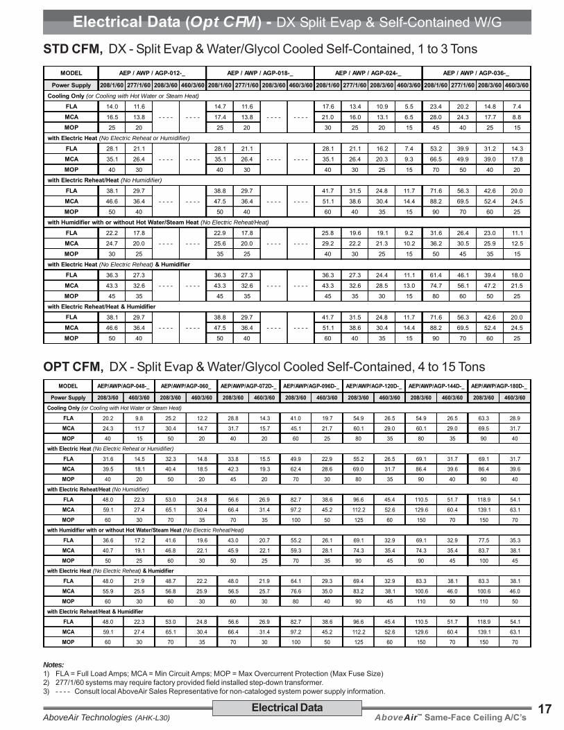
Electrical Data (Opt CFM) - DX Split Evap & Self-Contained W/G
MODEL AEP / AWP / AGP-012-_ AEP / AWP / AGP-018-_ AEP / AWP / AGP-024-_ AEP / AWP / AGP-036-_
Power Supply 208/1/60 277/1/60 208/3/60 460/3/60 208/1/60 277/1/60 208/3/60 460/3/60 208/1/60 277/1/60 208/3/60 460/3/60 208/1/60 277/1/60 208/3/60 460/3/60 Cooling Only (or Cooling with Hot Water or Steam Heat)
FLA 14.0 11.6
- - - - - - - -
14.7 11.6
- - - - - - - -
17.6 13.4 10.9 5.5 23.4 20.2 14.8 7.4
MCA 16.5 13.8 17.4 13.8 21.0 16.0 13.1 6.5 28.0 24.3 17.7 8.8
MOP 25 20 25 20 30 25 20 15 45 40 25 15
with Electric Heat (No Electric Reheat or Humidifier)
FLA 28.1 21.1
- - - - - - - -
28.1 21.1
- - - - - - - -
28.1 21.1 16.2 7.4 53.2 39.9 31.2 14.3
MCA 35.1 26.4 35.1 26.4 35.1 26.4 20.3 9.3 66.5 49.9 39.0 17.8
MOP 40 30 40 30 40 30 25 15 70 50 40 20
with Electric Reheat/Heat (No Humidifier)
FLA 38.1 29.7
- - - - - - - -
38.8 29.7
- - - - - - - -
41.7 31.5 24.8 11.7 71.6 56.3 42.6 20.0
MCA 46.6 36.4 47.5 36.4 51.1 38.6 30.4 14.4 88.2 69.5 52.4 24.5
MOP 50 40 50 40 60 40 35 15 90 70 60 25
with Humidifier with or without Hot Water/Steam Heat (No Electric Reheat/Heat)
FLA 22.2 17.8
- - - - - - - -
22.9 17.8
- - - - - - - -
25.8 19.6 19.1 9.2 31.6 26.4 23.0 11.1
MCA 24.7 20.0 25.6 20.0 29.2 22.2 21.3 10.2 36.2 30.5 25.9 12.5
MOP 30 25 35 25 40 30 25 15 50 45 35 15
with Electric Heat (No Electric Reheat) & HumidifierFLA 36.3 27.3
- - - - - - - -
36.3 27.3
- - - - - - - -
36.3 27.3 24.4 11.1 61.4 46.1 39.4 18.0
MCA 43.3 32.6 43.3 32.6 43.3 32.6 28.5 13.0 74.7 56.1 47.2 21.5
MOP 45 35 45 35 45 35 30 15 80 60 50 25
with Electric Reheat/Heat & HumidifierFLA 38.1 29.7
- - - - - - - -
38.8 29.7
- - - - - - - -
41.7 31.5 24.8 11.7 71.6 56.3 42.6 20.0
MCA 46.6 36.4 47.5 36.4 51.1 38.6 30.4 14.4 88.2 69.5 52.4 24.5
MOP 50 40 50 40 60 40 35 15 90 70 60 25
MODEL AEP/AWP/AGP-048-_ AEP/AWP/AGP-060_ AEP/AWP/AGP-072D-_ AEP/AWP/AGP-096D-_ AEP/AWP/AGP-120D-_ AEP/AWP/AGP-144D-_ AEP/AWP/AGP-180D-_
Power Supply 208/3/60 460/3/60 208/3/60 460/3/60 208/3/60 460/3/60 208/3/60 460/3/60 208/3/60 460/3/60 208/3/60 460/3/60 208/3/60 460/3/60 Cooling Only (or Cooling with Hot Water or Steam Heat)
FLA 20.2 9.8 25.2 12.2 28.8 14.3 41.0 19.7 54.9 26.5 54.9 26.5 63.3 28.9
MCA 24.3 11.7 30.4 14.7 31.7 15.7 45.1 21.7 60.1 29.0 60.1 29.0 69.5 31.7
MOP 40 15 50 20 40 20 60 25 80 35 80 35 90 40
with Electric Heat (No Electric Reheat or Humidifier)
FLA 31.6 14.5 32.3 14.8 33.8 15.5 49.9 22.9 55.2 26.5 69.1 31.7 69.1 31.7
MCA 39.5 18.1 40.4 18.5 42.3 19.3 62.4 28.6 69.0 31.7 86.4 39.6 86.4 39.6
MOP 40 20 50 20 45 20 70 30 80 35 90 40 90 40
with Electric Reheat/Heat (No Humidifier)
FLA 48.0 22.3 53.0 24.8 56.6 26.9 82.7 38.6 96.6 45.4 110.5 51.7 118.9 54.1
MCA 59.1 27.4 65.1 30.4 66.4 31.4 97.2 45.2 112.2 52.6 129.6 60.4 139.1 63.1
MOP 60 30 70 35 70 35 100 50 125 60 150 70 150 70
with Humidifier with or without Hot Water/Steam Heat (No Electric Reheat/Heat)
FLA 36.6 17.2 41.6 19.6 43.0 20.7 55.2 26.1 69.1 32.9 69.1 32.9 77.5 35.3
MCA 40.7 19.1 46.8 22.1 45.9 22.1 59.3 28.1 74.3 35.4 74.3 35.4 83.7 38.1
MOP 50 25 60 30 50 25 70 35 90 45 90 45 100 45
with Electric Heat (No Electric Reheat) & HumidifierFLA 48.0 21.9 48.7 22.2 48.0 21.9 64.1 29.3 69.4 32.9 83.3 38.1 83.3 38.1
MCA 55.9 25.5 56.8 25.9 56.5 25.7 76.6 35.0 83.2 38.1 100.6 46.0 100.6 46.0
MOP 60 30 60 30 60 30 80 40 90 45 110 50 110 50
with Electric Reheat/Heat & HumidifierFLA 48.0 22.3 53.0 24.8 56.6 26.9 82.7 38.6 96.6 45.4 110.5 51.7 118.9 54.1
MCA 59.1 27.4 65.1 30.4 66.4 31.4 97.2 45.2 112.2 52.6 129.6 60.4 139.1 63.1
MOP 60 30 70 35 70 30 100 50 125 60 150 70 150 70
STD CFM, DX - Split Evap & Water/Glycol Cooled Self-Contained, 1 to 3 Tons
OPT CFM, DX - Split Evap & Water/Glycol Cooled Self-Contained, 4 to 15 Tons
Notes:1) FLA = Full Load Amps; MCA = Min Circuit Amps; MOP = Max Overcurrent Protection (Max Fuse Size)2) 277/1/60 systems may require factory provided field installed step-down transformer.3) - - - - Consult local AboveAir Sales Representative for non-cataloged system power supply information.

AboveAir™ Same-Face Ceiling A/C’s AboveAir Technologies (AHK-L30)18 Electrical Data
Electrical Data (Standard CFM) - DX & CW Air Handling Units
LEDOM _-210-CCA&CHA _-810-CCA&CHA _-420-CCA&CHA _-630-CCA&CHA
ylppuSrewoP 06/1/802 06/1/772 06/3/802 06/3/064 06/1/802 06/1/772 06/3/802 06/3/064 06/1/802 06/1/772 06/3/802 06/3/064 06/1/802 06/1/772 06/3/802 06/3/064
ylnOgnilooC )taeHmaetSroretaWtoHhtiwgnilooCro(
ALF 0.4 0.3 3.2 2.1 0.4 0.3 3.2 2.1 0.4 0.3 3.2 2.1 0.5 8.3 4.3 7.1
ACM 0.5 8.3 9.2 4.1 0.5 8.3 9.2 4.1 0.5 8.3 9.2 4.1 3.6 7.4 3.4 1.2
POM 51 51 51 51 51 51 51 51 51 51 51 51 51 51 51 51
taeHcirtcelEhtiw )reifidimuHrotaeheRcirtcelEoN(
ALF 1.82 1.12 2.61 4.7 1.82 1.12 2.61 4.7 1.82 1.12 2.61 4.7 2.35 9.93 2.13 3.41
ACM 1.53 4.62 3.02 3.9 1.53 4.62 3.02 3.9 1.53 4.62 3.02 3.9 5.66 9.94 0.93 8.71
POM 04 03 52 51 04 03 52 51 04 03 52 51 07 05 04 02
taeH/taeheRcirtcelEhtiw )reifidimuHoN(
ALF 1.82 1.12 2.61 4.7 1.82 1.12 2.61 4.7 1.82 1.12 2.61 4.7 2.35 9.93 2.13 3.41
ACM 1.53 4.62 3.02 3.9 1.53 4.62 3.02 3.9 1.53 4.62 3.02 3.9 5.66 9.94 0.93 8.71
POM 04 03 52 51 04 03 52 51 04 03 52 51 07 05 04 02
taeHmaetS/retaWtoHtuohtiwrohtiwreifidimuHhtiw )taeH/taeheRcirtcelEoN(
ALF 2.21 2.9 5.01 9.4 2.21 2.9 5.01 9.4 2.21 2.9 5.01 9.4 2.31 0.01 6.11 4.5
ACM 2.31 0.01 1.11 1.5 2.31 0.01 1.11 1.5 2.31 0.01 1.11 1.5 5.41 9.01 5.21 8.5
POM 51 51 51 51 51 51 51 51 51 51 51 51 51 51 51 51
taeHcirtcelEhtiw )taeheRcirtcelEoN( reifidimuH&
ALF 3.63 3.72 4.42 1.11 3.63 3.72 4.42 1.11 3.63 3.72 4.42 1.11 4.16 1.64 4.93 0.81
ACM 3.34 6.23 5.82 0.31 3.34 6.23 5.82 0.31 3.34 6.23 5.82 0.31 7.47 1.65 2.74 5.12
POM 54 53 03 51 54 53 03 51 54 53 03 51 08 06 05 52
reifidimuH&taeH/taeheRcirtcelEhtiw
ALF 3.63 3.72 4.42 1.11 3.63 3.72 4.42 1.11 3.63 3.72 4.42 1.11 4.16 1.64 4.93 0.81
ACM 3.34 6.23 5.82 0.31 3.34 6.23 5.82 0.31 3.34 6.23 5.82 0.31 7.47 1.65 2.74 5.12
POM 54 53 03 51 54 53 03 51 54 53 03 51 08 06 05 52
LEDOM _-840-CCA/CHA _060-CCA/CHA _-270-CCA/CHA _-690-CCA/CHA _-021-CCA/CHA _-441-CCA/CHA _-081-CCA/CHA
ylppuSrewoP 06/3/802 06/3/064 06/3/802 06/3/064 06/3/802 06/3/064 06/3/802 06/3/064 06/3/802 06/3/064 06/3/802 06/3/064 06/3/802 06/3/064
ylnOgnilooC )taeHmaetSroretaWtoHhtiwgnilooCro(
ALF 4.3 7.1 8.3 9.1 5.4 2.2 0.6 9.2 2.8 0.4 5.31 5.6 5.31 5.6
ACM 3.4 1.2 8.4 4.2 6.5 8.2 5.7 6.3 3.01 0.5 9.61 1.8 9.61 1.8
POM 51 51 51 51 51 51 51 51 51 51 03 51 03 51
taeHcirtcelEhtiw )reifidimuHrotaeheRcirtcelEoN(
ALF 2.13 3.41 6.13 5.41 3.23 8.41 7.74 8.12 9.94 9.22 1.96 7.13 1.96 7.13
ACM 0.93 8.71 5.93 1.81 4.04 5.81 6.95 2.72 4.26 6.82 4.68 6.93 4.68 6.93
POM 04 02 04 02 54 02 06 03 07 03 09 04 09 04
taeH/taeheRcirtcelEhtiw )reifidimuHoN(
ALF 2.13 3.41 6.13 5.41 3.23 8.41 7.74 8.12 9.94 9.22 1.96 7.13 1.96 7.13
ACM 0.93 8.71 5.93 1.81 4.04 5.81 6.95 2.72 4.26 6.82 4.68 6.93 4.68 6.93
POM 04 02 04 02 54 02 06 03 07 03 09 04 09 04
taeHmaetS/retaWtoHtuohtiwrohtiwreifidimuHhtiw )taeH/taeheRcirtcelEoN(
ALF 8.91 1.9 2.02 3.9 7.81 6.8 2.02 3.9 4.22 4.01 7.72 9.21 7.72 9.21
ACM 7.02 5.9 2.12 8.9 8.91 2.9 7.12 0.01 5.42 4.11 1.13 5.41 1.13 5.41
POM 52 51 52 51 02 51 52 51 03 51 04 02 04 02
taeHcirtcelEhtiw )taeheRcirtcelEoN( reifidimuH&
ALF 6.74 7.12 0.84 9.12 5.64 2.12 9.16 2.82 1.46 3.92 3.38 1.83 3.38 1.83
ACM 4.55 2.52 9.55 5.52 6.45 9.42 8.37 6.33 6.67 0.53 6.001 0.64 6.001 0.64
POM 06 03 06 03 06 52 08 53 08 04 011 05 011 05
reifidimuH&taeH/taeheRcirtcelEhtiw
ALF 6.74 7.12 0.84 9.12 5.64 2.12 9.16 2.82 1.46 3.92 3.38 1.83 3.38 1.83
ACM 4.55 2.52 9.55 5.52 6.45 9.42 8.37 6.33 6.67 0.53 6.001 0.64 6.001 0.64
POM 06 03 06 03 06 52 08 53 08 04 011 05 011 05
STANDARD CFM, DX-Split & Chilled Water Air Handling Evaps, 1 to 3 Tons
STANDARD CFM, DX-Split & Chilled Water Air Handling Evaps, 6 to 15 Tons
Notes:1) FLA = Full Load Amps; MCA = Min Circuit Amps; MOP = Max Overcurrent Protection (Max Fuse Size)2) - - - - Consult local AboveAir Sales Representative for non-cataloged system power supply information.

AboveAir™ Same-Face Ceiling A/C’sAboveAir Technologies (AHK-L30)19Electrical Data
Electrical Data (Optional CFM) - DX & CW Air Handling Units
LEDOM _-210-PCA&PHA _-810-PCA&PHA _-420-PCA&PHA _-630-PCA&PHA
ylppuSrewoP 06/1/802 06/1/772 06/3/802 06/3/064 06/1/802 06/1/772 06/3/802 06/3/064 06/1/802 06/1/772 06/3/802 06/3/064 06/1/802 06/1/772 06/3/802 06/3/064
ylnOgnilooC )taeHmaetSroretaWtoHhtiwgnilooCro(
ALF 0.4 0.3 3.2 2.1 0.4 0.3 3.2 2.1 0.4 0.3 3.2 2.1 0.5 8.3 4.3 7.1
ACM 0.5 8.3 9.2 4.1 0.5 8.3 9.2 4.1 0.5 8.3 9.2 4.1 3.6 7.4 3.4 1.2
POM 51 51 51 51 51 51 51 51 51 51 51 51 51 51 51 51
taeHcirtcelEhtiw )reifidimuHrotaeheRcirtcelEoN(
ALF 1.82 1.12 2.61 4.7 1.82 1.12 2.61 4.7 1.82 1.12 2.61 4.7 2.35 9.93 2.13 3.41
ACM 1.53 4.62 3.02 3.9 1.53 4.62 3.02 3.9 1.53 4.62 3.02 3.9 5.66 9.94 0.93 8.71
POM 04 03 52 51 04 03 52 51 04 03 52 51 07 05 04 02
taeH/taeheRcirtcelEhtiw )reifidimuHoN(
ALF 1.82 1.12 2.61 4.7 1.82 1.12 2.61 4.7 1.82 1.12 2.61 4.7 2.35 9.93 2.13 3.41
ACM 1.53 4.62 3.02 3.9 1.53 4.62 3.02 3.9 1.53 4.62 3.02 3.9 5.66 9.94 0.93 8.71
POM 04 03 52 51 04 03 52 51 04 03 52 51 07 05 04 02
taeHmaetS/retaWtoHtuohtiwrohtiwreifidimuHhtiw )taeH/taeheRcirtcelEoN(
ALF 2.21 2.9 5.01 9.4 2.21 2.9 5.01 9.4 2.21 2.9 5.01 9.4 2.31 0.01 6.11 4.5
ACM 2.31 0.01 1.11 1.5 2.31 0.01 1.11 1.5 2.31 0.01 1.11 1.5 5.41 9.01 5.21 8.5
POM 51 51 51 51 51 51 51 51 51 51 51 51 51 51 51 51
taeHcirtcelEhtiw )taeheRcirtcelEoN( reifidimuH&
ALF 3.63 3.72 4.42 1.11 3.63 3.72 4.42 1.11 3.63 3.72 4.42 1.11 4.16 1.64 4.93 0.81
ACM 3.34 6.23 5.82 0.31 3.34 6.23 5.82 0.31 3.34 6.23 5.82 0.31 7.47 1.65 2.74 5.12
POM 54 53 03 51 54 53 03 51 54 53 03 51 08 06 05 52
reifidimuH&taeH/taeheRcirtcelEhtiw
ALF 3.63 3.72 4.42 1.11 3.63 3.72 4.42 1.11 3.63 3.72 4.42 1.11 4.16 1.64 4.93 0.81
ACM 3.34 6.23 5.82 0.31 3.34 6.23 5.82 0.31 3.34 6.23 5.82 0.31 7.47 1.65 2.74 5.12
POM 54 53 03 51 54 53 03 51 54 53 03 51 08 06 05 52
LEDOM _-840-PCA/PHA _060-PCA/PHA _-270-PCA/PHA _-690-PCA/PHA _-021-PCA/PHA _-441-PCA/PHA _-081-PCA/PHA
ylppuSrewoP 06/3/802 06/3/064 06/3/802 06/3/064 06/3/802 06/3/064 06/3/802 06/3/064 06/3/802 06/3/064 06/3/802 06/3/064 06/3/802 06/3/064
ylnOgnilooC )taeHmaetSroretaWtoHhtiwgnilooCro(
ALF 8.3 9.1 5.4 2.2 0.6 9.2 2.8 0.4 5.31 5.6 5.31 5.6 5.31 5.6
ACM 8.4 4.2 6.5 8.2 5.7 6.3 3.01 0.5 9.61 1.8 9.61 1.8 9.61 1.8
POM 51 51 51 51 51 51 51 51 03 51 03 51 03 51
taeHcirtcelEhtiw )reifidimuHrotaeheRcirtcelEoN(
ALF 6.13 5.41 3.23 8.41 8.33 5.51 9.94 9.22 2.55 4.52 1.96 7.13 1.96 7.13
ACM 5.93 1.81 4.04 5.81 3.24 3.91 4.26 6.82 0.96 7.13 4.68 6.93 4.68 6.93
POM 04 02 54 02 54 02 07 03 07 53 09 04 09 04
taeH/taeheRcirtcelEhtiw )reifidimuHoN(
ALF 6.13 5.41 3.23 8.41 8.33 5.51 9.94 9.22 2.55 4.52 1.96 7.13 1.96 7.13
ACM 5.93 1.81 4.04 5.81 3.24 3.91 4.26 6.82 0.96 7.13 4.68 6.93 4.68 6.93
POM 04 02 54 02 54 02 07 03 07 53 09 04 09 04
taeHmaetS/retaWtoHtuohtiwrohtiwreifidimuHhtiw )taeH/taeheRcirtcelEoN(
ALF 2.02 3.9 9.02 6.9 2.02 3.9 4.22 4.01 7.72 9.21 7.72 9.21 7.72 9.21
ACM 2.12 8.9 0.22 2.01 7.12 0.01 5.42 4.11 1.13 5.41 1.13 5.41 1.13 5.41
POM 52 51 52 51 52 51 03 51 04 02 04 02 04 02
taeHcirtcelEhtiw )taeheRcirtcelEoN( reifidimuH&
ALF 0.84 9.12 7.84 2.22 0.84 9.12 1.46 3.92 4.96 8.13 3.38 1.83 3.38 1.83
ACM 9.55 5.52 8.65 9.52 5.65 7.52 6.67 0.53 2.38 1.83 6.001 0.64 6.001 0.64
POM 06 03 06 03 06 03 08 04 09 04 011 05 011 05
reifidimuH&taeH/taeheRcirtcelEhtiw
ALF 0.84 9.12 7.84 2.22 0.84 9.12 1.46 3.92 4.96 8.13 3.38 1.83 3.38 1.83
ACM 9.55 5.52 8.65 9.52 5.65 7.52 6.67 0.53 2.38 1.83 6.001 0.64 6.001 0.64
POM 06 03 06 03 06 03 08 04 09 04 011 05 011 05
OPTIONAL CFM, DX-Split & Chilled Water Air Handling Evaps, 1 to 3 Tons
OPTIONAL CFM, DX-Split & Chilled Water Air Handling Evaps, 6 to 15 Tons
Notes:1) FLA = Full Load Amps; MCA = Min Circuit Amps; MOP = Max Overcurrent Protection (Max Fuse Size)2) - - - - Consult local AboveAir Sales Representative for non-cataloged system power supply information.

AboveAir™ Same-Face Ceiling A/C’s AboveAir Technologies (AHK-L30)20 Electrical Data
Electrical Data - Air Cooled, Remote Condensing UnitsOutdoor Mtd - DX - Air Cooled, Remote Condensing Units
XPU - SINGLE Compressor, Outdoor Propeller FanAir Cooled Remote Condensing Units
XPU - DUAL Compressors, Outdoor Propeller FanAir Cooled Remote Condensing Units
Power Supply 208/1/60 277/1/60 208/3/60 460/3/60 Power Supply 208/1/60 277/1/60 208/3/60 460/3/60XPU-012 XPU-096D
FLA 9.5 7.1
- - - - - - - -
FLA- - - - - - - -
35.0 17.1
MCA 11.8 8.8 MCA 39.0 19.1
MOP 20 15 MOP 50 25
XPU-018 XPU-120DFLA 10.4 7.8
- - - - - - - -
FLA- - - - - - - -
35.0 17.1
MCA 17.6 13.2 MCA 39.0 19.1
MOP 30 20 MOP 50 25
XPU-024 XPU-144DFLA 13.6 10.2 9.1 5.2 FLA
- - - - - - - -
47.8 22.7
MCA 16.8 12.6 11.2 6.3 MCA 53.4 25.5
MOP 25 20 20 15 MOP 60 30
XPU-036 XPU-180DFLA 19.0 14.3 14.6 6.6 FLA
- - - - - - - -
53.0 25.9
MCA 23.5 17.6 18.0 8.1 MCA 60.7 29.8
MOP 40 30 30 15 MOP 80 40
XPU-048FLA 21.3 16.0 15.1 7.1
MCA 26.2 19.7 18.4 8.6
MOP 40 35 30 15
XPU-060FLA 27.6 20.7 18.0 8.8
MCA 34.2 25.7 22.0 10.8
MOP 50 45 30 15
XPU-072FLA
- - - - - - - -
22.0 11.2
MCA 26.8 13.7
MOP 45 20
XPU-090FLA
- - - - - - - -
28.0 13.7
MCA 34.2 16.9
MOP 50 25
Qty. one XPU condensing unit is provided per circuit:• AHC/P-072 units are provided with qty. 2 x XPU-036 units• AHC/P-096 units are provided with qty. 2 x XPU-048 units• AHC/P-120 units are provided with qty. 2 x XPU-060 units• AHC/P-144 units are provided with qty. 2 x XPU-072 units• AHC/P-180 units are provided with qty. 2 x XPU-090 units
Notes:1) FLA = Full Load Amps; MCA = Min Circuit Amps; MOP = Max Overcurrent Protection (Max Fuse Size)2) 277/1/60 systems may require factory provided field installed step-down transformer.3) The above unit electrical data is reflective of the standard performance data and standard options as shown in this manual.4) - - - - Consult local AboveAir Sales Representative for non-cataloged system power supply information.

AboveAir™ Same-Face Ceiling A/C’sAboveAir Technologies (AHK-L30)21Electrical Data
Electrical Data - Water/Glycol Cooled, Remote CondensingOutdoor Mtd - DX - Air Cooled, Remote Condensing Units & Condensers
XP1 & XP2 - ("Wrap-Around Coil") - Outdoor Propeller FanAir Cooled Remote Condensers
WP1 & WP2 - ("Slab Coil") - Outdoor Propeller FanAir Cooled Remote Condensers
Power Supply 208/1/60 277/1/60 460/1/60 208/3/60 460/3/60 Power Supply 208/1/60 277/1/60 460/1/60 208/3/60 460/3/60XP1-012 WP1-108D
FLA 0.5 0.4 0.6
- - - - - - - -
FLA 4.4 3.3 2.2
- - - - - - - -MCA 0.6 0.5 0.8 MCA 5.5 4.1 5.4
MOP 15 15 15 MOP 15 15 15
XP1-018 WP1-132DFLA 0.8 0.6 0.6
- - - - - - - -
FLA 4.4 3.3 2.2
- - - - - - - -MCA 1.0 0.8 0.8 MCA 5.5 4.1 5.4MOP 15 15 15 MOP 15 15 15
XP1-024 WP1-156DFLA 0.8 0.6 0.7
- - - - - - - -
FLA 4.4 3.3 2.2
- - - - - - - -MCA 1.0 0.8 0.9 MCA 5.5 4.1 5.4
MOP 15 15 15 MOP 15 15 15
XP1-030 WP2-204DFLA 1.1 0.8 0.6
- - - - - - - -
FLA 9.4 7.1
- - - -
13.0 6.6
MCA 1.4 1.0 0.8 MCA 10.6 8.0 14.6 7.4
MOP 15 15 15 MOP 15 15 20 15
XP1-036 WP2-252DFLA 1.1 0.8 0.6
- - - - - - - -
FLA 9.4 7.1
- - - -
13.0 6.6
MCA 1.4 1.0 0.8 MCA 10.6 8.0 14.6 7.4
MOP 15 15 15 MOP 15 15 20 15
XP1-042FLA 2.0 1.5 1.0
- - - - - - - -MCA 2.5 1.9 1.3
MOP 15 15 15
XP1-048FLA 2.0 1.5 1.0
- - - - - - - -MCA 2.5 1.9 1.3
MOP 15 15 15
XP1-060FLA 2.0 1.5 1.0
- - - - - - - -MCA 2.5 1.9 1.3MOP 15 15 15
XP1-072FLA 5.6 4.2 3.5
- - - - - - - -MCA 7.0 5.3 7.0
MOP 15 15 15
Notes:1) FLA = Full Load Amps; MCA = Min Circuit Amps; MOP = Max Overcurrent Protection (Max Fuse Size)2) 277/1/60 systems may require factory provided field installed step-down transformer.3) The above unit electrical data is reflective of the standard performance data and standard options as shown in this manual.4) - - - - Consult local AboveAir Sales Representative for non-cataloged system power supply information.

AboveAir™ Same-Face Ceiling A/C’s AboveAir Technologies (AHK-L30)22 Electrical Data
Electrical Data - Air Cooled, Remote Condensing Units & Condensers
XCU - Indoor (Ceiling Mtd), Centrifugal BlowerAir Cooled Remote Condensing Units
XCX - Indoor (Ceiling Mtd), Centrifugal BlowerAir Cooled Remote Condensers
Power Supply 208/1/60 277/1/60 208/3/60 460/3/60 Power Supply 208/1/60 277/1/60 208/3/60 460/3/60XCU-012 XCX-012
FLA 14.0 11.6
- - - - - - - -
FLA 4.5 3.4 2.3 1.2
MCA 16.5 13.8 MCA 5.6 4.2 4.3 2.4
MOP 25 20 MOP 15 15 15 15
XCU-018 XCX-018FLA 14.7 11.6
- - - - - - - -
FLA 5.5 4.1 3.4 1.9
MCA 17.4 13.8 MCA 6.9 5.2 4.3 2.4
MOP 25 20 MOP 15 15 15 15
XCU-024 XCX-024FLA 18.6 14.2 12.0 6.0 FLA 5.5 4.1 3.4 1.9
MCA 22.0 16.8 14.2 7.1 MCA 6.9 5.2 4.3 2.4
MOP 35 25 20 15 MOP 15 15 15 15
XCU-036 XCX-036FLA 25.1 21.4 15.2 7.6 FLA 6.7 5.0 3.8 1.9
MCA 29.7 25.5 18.1 9.0 MCA 8.4 6.3 4.8 2.4
MOP 45 40 25 15 MOP 15 15 15 15
XCU-048 XCX-048FLA 31.0
- - - -
20.2 9.8 FLA 6.7 5.0 3.8 1.9
MCA 37.1 24.3 11.7 MCA 8.4 6.3 4.8 2.4
MOP 60 40 15 MOP 15 15 15 15
XCU-060 XCX-060FLA 41.1
- - - -
25.2 12.2 FLA 9.0 6.8 5.6 2.8
MCA 49.1 30.4 14.7 MCA 11.3 8.4 7.0 3.5
MOP 80 50 20 MOP 20 15 15 15
XCU-072 XCX-072FLA
- - - - - - - -
28.8 14.3 FLA- - - - - - - -
7.0 3.5
MCA 31.7 15.7 MCA 8.8 4.4
MOP 40 20 MOP 15 15
XCU-096 XCX-096FLA
- - - - - - - -
41.0 19.7 FLA- - - - - - - -
8.8 4.4
MCA 45.1 21.7 MCA 11.0 5.5
MOP 60 25 MOP 15 15
XCU-120 XCX-120FLA
- - - - - - - -
54.9 26.5 FLA- - - - - - - -
13.6 6.6
MCA 60.1 29.0 MCA 17.0 8.3
MOP 80 35 MOP 30 15
XCU-144 XCX-144FLA
- - - - - - - -
54.9 26.5 FLA- - - - - - - -
19.4 9.0
MCA 60.1 29.0 MCA 24.3 11.3
MOP 80 35 MOP 40 20
XCU-180 XCX-180FLA
- - - - - - - -
63.3 28.9 FLA- - - - - - - -
19.4 9.0
MCA 69.5 31.7 MCA 24.3 11.3
MOP 90 40 MOP 40 20
Indoor, Ceiling Mtd - DX - Air Cooled, Remote Condensing Units & Condensers
Notes:1) FLA = Full Load Amps; MCA = Min Circuit Amps; MOP = Max Overcurrent Protection (Max Fuse Size)2) 277/1/60 systems may require factory provided field installed step-down transformer.3) The above unit electrical data is reflective of the standard performance data and standard options as shown in this manual.4) - - - - Consult local AboveAir Sales Representative for non-cataloged system power supply information.

AboveAir™ Same-Face Ceiling A/C’sAboveAir Technologies (AHK-L30)23Electrical Data
Electrical Data - Water/Glycol Cooled, Remote Condensing Units
)roodtuOlanoitpO(/roodnI-UGX&UWXstinUgnisnednoCetomeRdelooClocylG&retaW
ylppuSrewoP 06/1/802 06/1/772 06/3/802 06/3/064 ylppuSrewoP 06/1/802 06/1/772 06/3/802 06/3/064
210-UGX&UWX 270-UGX&UWX
ALF 0.01 6.8
---- ----
ALF
---- ----
8.22 4.11
ACM 5.21 8.01 ACM 7.52 8.21
POM 02 51 POM 53 51
810-UGX&UWX 690-UGX&UWX
ALF 7.01 6.8
---- ----
ALF
---- ----
8.23 7.51
ACM 4.31 8.01 ACM 9.63 7.71
POM 02 51 POM 05 52
420-UGX&UWX 021-UGX&UWX
ALF 6.31 4.01 6.8 3.4 ALF
---- ----
4.14 0.02
ACM 0.71 0.31 8.01 4.5 ACM 6.64 5.22
POM 03 02 51 51 POM 06 03
630-UGX&UWX 441-UGX&UWX
ALF 4.81 4.61 4.11 7.5 ALF
---- ----
4.14 0.02
ACM 0.32 5.02 3.41 1.7 ACM 6.64 5.22
POM 04 53 52 51 POM 06 03
840-UGX&UWX 081-UGX&UWX
ALF 3.42
----
4.61 9.7 ALF
---- ----
8.94 4.22
ACM 4.03 5.02 8.9 ACM 0.65 2.52
POM 05 53 51 POM 08 53
060-UGX&UWX
ALF 1.23
----
7.02 0.01
ACM 1.04 9.52 5.21
POM 07 54 02
Indoor, Ceiling Mtd - DX - Water / Glycol Cooled, Remote Condensing Units
Notes:1) FLA = Full Load Amps; MCA = Min Circuit Amps; MOP = Max Overcurrent Protection (Max Fuse Size)2) 277/1/60 systems may require factory provided field installed step-down transformer.3) The above unit electrical data is reflective of the standard performance data and standard options as shown in this manual.4) - - - - Consult local AboveAir Sales Representative for non-cataloged system power supply information.
AboveAir™ Same-Face Ceiling A/C’s AboveAir Technologies (AHK-L30)24 Guide Specifications
Guide Specifications - Horizontal High Static Systems (1-15 Tons)
1.0 General 1.1 Summary
These specifications describe the require-ments for a horizontal ceiling mounted airconditioner. The system shall be designedto control space temperature and humidity.
The air conditioning manufacturer shalldesign and furnish all equipment in thequantities and configurations shown on theproject plans and specifications.
The system shall be provided by AboveAirTechnologies in Frederick, Maryland, USA.The system shall be listed by Intertek (ETLSemko), Inc. to conform with UL Std 1995and be certified to CAN/CSA Std C22.2 No.236 (Control No. 3091370). The systemshall be NYC MEA230-06-E and ChicagoCode Approved. The system modelnumber shall be _____________.
1.2 Design RequirementsThe system shall be an AboveAir HK-Horizontal™ brand factory assembled andtested. Evaporator sections shall bedesigned for above the drop-ceilinginstallation. Remote condensing unitsections shall be designed for eitheroutdoor or indoor above the drop-ceilinginstallation.
Evaporators and indoor remote condensingunit sections shall be designed for ductedsame-face air distribution.
The system shall have a total coolingcapacity of ______ BTU/H, and a sensiblecooling capacity of ______ BTU/H, basedon an entering air condition of ______ °FDB, and ______ °F WB, ______ % RH.
The evaporator section shall be designedfor _____ Volt, ______ Phase, _____ Hertzmain power supply. The remote condens-ing unit section (if applicable) shall bedesigned for _____ Volt, ______ Phase,_____ Hertz main power supply.
1.3 SubmittalsSubmittals shall be provided aftermanufacturer’s receipt of a writtenpurchase order and shall include: DetailedPerformance and Electrical Data; GuideSpecifications; and Dimensional Drawings.
1.4 Quality AssuranceThe system shall be factory tested prior toshipment. Testing shall include, but shallnot be limited to: system and componentoperational and functional testing; electrical“HiPot” insulation test; refrigerant and waterpiping circuit pressuring testing per UL 1995Safety Standard for Heating and CoolingEquipment. The system shall be designedand manufactured according to world classquality standards.
2.0 Products
2.1 Standard Features /All Systems
2.1.1 CabinetThe cabinet chassis and access panelsshall be constructed of heavy gaugegalvanized steel. Cabinet access panelsshall rest in recessed pockets designed forminimum air leakage. The cabinet andaccess panels shall be lined with 2 lb/ft2high density sound and thermal insulationconforming to NFPA 90A and 90B.
2.1.2 Component AccessThe unit shall be serviceable within theceiling through large side access panels.
2.1.3 Electrical SystemGeneral:The electrical system shall conform toNational Electric Code (NEC) requirementsaccording to UL 1995. The control circuitshall be a 24 VAC low voltage circuit.
The electrical system shall include, but notbe limited to the following factory installeditems: 24 VAC control transformer;terminal connections; grounding lug;overload protection; and starter/contactorsfor blower motor, compressor, humidifierand electric heater stage (if applicable).
Packaged Systems: (single point power)Self-Contained systems shall be designedfor single point main power connection.
Split DX Systems: (separate power)Split systems shall require separate mainpower supplies to the evaporator andcondensing unit sections. The evaporatorand condensing unit sections shall beelectrically interlocked by a field wired 24volt control signal.
Overflow Safety Float:The system shall be provided with a factoryinstalled float type condensate pan overflowsafety switch. The circuit shall be designedto shut down all system water producing
operations in the event of an overflowcondition.
2.1.4 Air DistributionThe system air distribution shall beconfigured for a draw-through air pattern toprovide even air distribution and maximumcoil performance.
2.1.4.1 Evaporator Blower/Motor
The evaporator blower assembly shall bedesigned for ____ CFM @ ____ inchesexternal static pressure (e.s.p.)
The blower shall be the belt-drivencentrifugal type, double width double inlet(DWDI), and statically and dynamicallybalanced to a minimum vibration level. Theshaft shall be heavy duty steel with self-aligning ball bearings sized for an average100,000 hours of service life.
The blower motor shall be ____ Hp at 1725RPM (or 3450 RPM) and mounted on anadjustable base. Belts shall be sized for200% of the motor horsepower rating.Motors shall have overload protection and aminimum NEMA service factor of 1.15.
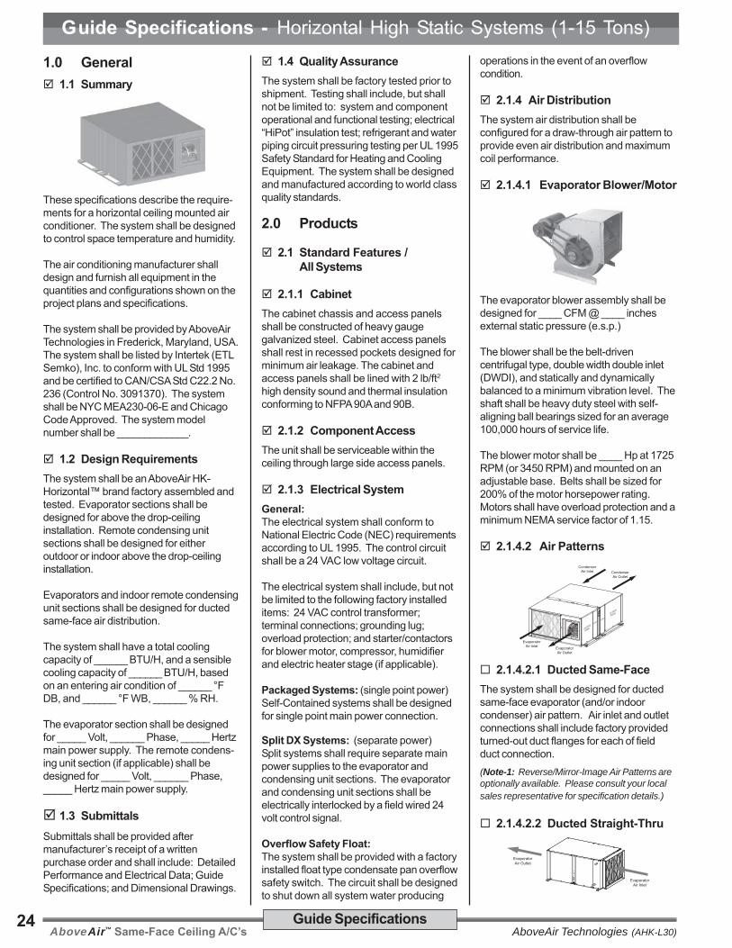
2.1.4.2 Air Patterns
EvaporatorAir Outlet
CondenserAir Outlet
EvaporatorAir Inlet
CondenserAir Inlet
ACCESS
PANEL
ACCESS
PANEL
E-BoxE-Box
2.1.4.2.1 Ducted Same-FaceThe system shall be designed for ductedsame-face evaporator (and/or indoorcondenser) air pattern. Air inlet and outletconnections shall include factory providedturned-out duct flanges for each of fieldduct connection.(Note-1: Reverse/Mirror-Image Air Patterns areoptionally available. Please consult your localsales representative for specification details.)
2.1.4.2.2 Ducted Straight-Thru
EvaporatorAir Inlet
EvaporatorAir Outlet

AboveAir™ Same-Face Ceiling A/C’sAboveAir Technologies (AHK-L30)25Guide Specifications
Guide Specifications - Horizontal High Static Systems (1-15 Tons)The system shall be designed for ductedstraight-thru evaporator air pattern. Air inletand outlet connections shall include factoryprovided turned-out duct flanges for each offield duct connection.
2.1.4.2.3 Ducted 90°/Right-Angle
EvaporatorAir InletEvaporator
Air Outlet
The system shall be designed for ducted90°/Right-Angle evaporator air pattern. Airinlet and outlet connections shall includefactory provided turned-out duct flanges foreach of field duct connection.
2.1.4.3 Air FiltrationThe filter(s) shall be 2 inch thick pleatedand rated for 30% dust spot efficiency(based on ASHRAE 52.1). The filter(s)shall be serviceable through a side accesspanel without shutting down the system.
2.2 Direct Expansion Systems
2.2.1 DX - Evaporator Coils
The DX evaporator coil shall be con-structed of copper tubes and aluminumfins. The system shall be designed for adraw-through air pattern for maximum heattransfer. Coil end-plates shall be hot dippedgalvanized. The evaporator coil shall bemounted in an insulated stainless steelcondensate drain pan.
2.2.2 Compressors
Each compressor shall be the highefficiency, low sound power scroll type.Each compressor shall be mounted onvibration isolators. Each compressor shallbe complete with reversible positive oilpump, charging and service ports, internalspring isolation, and discharge gas vibrationeliminator.
2.2.3 DX - Refrigeration Circuits
Each refrigeration circuit shall be pre-pipedwith refrigerant copper tubing. Therefrigeration system shall include, but notbe limited to: expansion valve with externalequalizer; sight glass; refrigerant filter-drier;shraeder service valves and high & lowrefrigerant pressure safety switches.
2.3 Standard Features /Individual Systems
2.3.1 DX - Air Cooled Systems
2.3.1.1 DX - Air Cooled(Self-Contained Systems)AAC/AAP-( )
EvaporatorAir Outlet
CondenserAir Outlet
EvaporatorAir Inlet
CondenserAir Inlet
ACCESS
PANEL
ACCESS
PANEL
E-BoxE-Box
The system shall be a self-contained,ceiling mounted air conditioner with factorymounted integral dx air cooled condensingunit with belt-driven centrifugal blower. Thecondensing unit shall be sized for full heatof rejection at 95°F ambient and be capableof operation to ___ °F low ambient airtemperature
The system shall require only single pointmain power supply and ship from thefactory with a full operating refrigerantcharge (1-8 Ton units). AAC/P-012/096models shall ship from the factory as one-piece units, while AAC/P-120/180 modelsshall ship split from the factory and requirefield packaged unit assembly and refriger-ant charging.(Note-1: Select 0°F Low Ambient Damperoption or -30°F Flooded Condenser low ambienthead pressure control as application requires -see options for more detail.)
2.3.1.2 DX - Air Cooled Split(Air Handler & IndoorRemote Condensing Unit)AHC/AHP-( ) & XCU-( )
CondenserAir Outlet Condenser
Air Inlet
ACCESS
PANEL
EvaporatorAir Inlet Evaporator
Air Outlet
ACCESS
PANELE-Box
The system shall be a split configurationwith indoor ceiling mounted dx air handlingunit and remote indoor (optional outdoor) aircooled belt-driven centrifugal blowercondensing unit. The compressor(s) shallbe located in the condensing unit. Thecondensing unit shall be sized for full heatof rejection at 95°F ambient and be capableof operation to ___ °F low ambient airtemperature.
The system shall factory tested prior toshipment. The air handling and condensingunit sections shall ship separately from thefactory with a dry-nitrogen holding chargefor field sweat (copper) connection andrefrigerant charging.
2.3.1.3 DX - Air Cooled Split(Air Handling & OutdoorRemote Condensing Units)AHC/AAP-( ) & XPU-( )
EvaporatorAir Inlet Evaporator
Air Outlet
ACCESS
PANELE-Box
The system shall be a split configurationwith indoor ceiling mounted dx air handlingunit and a remote outdoor air cooledpropeller fan condensing unit for eachrefrigerant circuit. Each compressor shallbe located in the condensing unit. Thecondensing unit shall be sized for full heatof rejection at 95°F ambient and be capableof operation to ___ °F low ambient airtemperature.
The system shall factory tested prior toshipment. The air handling and condensingunit sections shall ship separately from thefactory with a dry-nitrogen holding chargefor field sweat (copper) connection andrefrigerant charging.(Note-1: Select 0°F Fan Cycling, -20°F FanSpeed or -30°F Flooded Condenser low ambienthead pressure control as application requires -see options for more details.)
2.3.1.4 DX - Air Cooled Split(Split Evap & OutdoorRemote Condenser)AEC/AEP-( ) & XP1 or XP2-( )
EvaporatorAir Inlet Evaporator
Air Outlet
ACCESS
PANELE-Box

AboveAir™ Same-Face Ceiling A/C’s AboveAir Technologies (AHK-L30)26 Guide Specifications
Guide Specifications - Horizontal High Static Systems (1-15 Tons)The system shall be a split configurationwith iindoor ceiling mounted dx evaporatorand outdoor dx air cooled propeller fanremote condenser. The compressor shallbe located in the indoor evaporator section.The condenser shall be sized for full heat ofrejection at 95°F ambient and be capable ofoperation to ___ °F low ambient airtemperature.
The system shall be refrigerant chargedand run tested at the factory prior toshipment. The evaporator and condensersections shall ship separately with a dry-nitrogen charge ready for field refrigerantcharging.(Note-1: See 2.4.1 pg 12 Low Amb. Options.)
2.3.1.6 DX - Air Cooled Split(Split Evap & OutdoorRemote Condenser)AEC/AEP-( ) & XCX-( )
CondenserAir Outlet Condenser
Air Inlet
ACCESS
PANEL
EvaporatorAir Inlet Evaporator
Air Outlet
ACCESS
PANELE-Box
The system shall be a split configurationwith iindoor ceiling mounted dx evaporatorand indoor dx air cooled belt-drivencentrifugal blower remote condenser. Thecompressor shall be located in the indoorevaporator section. The condenser shallbe sized for full heat of rejection at 95°Fambient and be capable of operation to ___°F low ambient air temperature.
The system shall be refrigerant chargedand run tested at the factory prior toshipment. The evaporator and condensersections shall ship separately with a dry-nitrogen charge ready for field refrigerantcharging.(Note-1: See 2.4.1 pg 12 Low Amb. Options.)
2.3.1.7 DX - Air Cooled RemoteCondensing Unit(Indoor/Outdoor CentrifugalBlower Configuration)XCU-( ) Only
CondenserAir Outlet Condenser
Air Inlet
ACCESS
PANEL
The system shall be a indoor horizontalceiling mounted (optional outdoor) remoteair cooled belt-driven centrifugal blowercondensing unit. The remote condensingunit shall include, but not be limited to:condenser coil; centrifugal belt-driven
blower and blower motor; compressor;sight glass; refrigerant filter-drier; shraederservice valves; high & low refrigerantpressure switches; grounding lug; 24 Vaccontrol transformer; individual blower motorand compressor starters/contactors; andterminal strip.
The condensing unit shall be sized for fullheat of rejection at 95°F ambient and becapable of operation to ___ °F low ambientair temperature.
The condensing unit shall ship from thefactory with a dry-nitrogen holding chargefor field sweat (copper) connection andrefrigerant charging.(Note-1: Select 0°F Low Ambient Damperoption or -30°F Flooded Condenser low ambienthead pressure control as applications requires -see options for more detail.)
2.3.2 DX - Air Handling UnitAHC/AHP-( ) Only
EvaporatorAir Inlet Evaporator
Air Outlet
ACCESS
PANELE-Box
The system shall be a split indoor horizon-tal ceiling mounted dx air handling unitdesigned for field connection to thespecified remote condensing unit (air, wateror glycol cooled). The air handling unit shallinclude, but not be limited to: evaporatorcoil; centrifugal belt-driven blower andblower motor; thermal expansion valve,shraeder service valves; grounding lug; 24Vac control transformer; individual blowermotor, humidifier, heater starters/contactors(if applicable); and terminal strip.
The air handling unit shall ship from thefactory with a dry-nitrogen holding chargefor field sweat (copper) connection andrefrigerant charging.
2.3.3 DX - Water Cooled Systems
2.3.3.1 DX - Water Cooled(Self-Contained Systems)AWC / AWP-( )
EvaporatorAir Outlet
EvaporatorAir Inlet
ACCESS
PANEL
ACCESS
PANEL
The system shall be a self-contained,ceiling mounted air conditioner with integraldx water cooled condensing unit. Eachrefrigerant circuit shall include a watercooled coaxial (or SS brazed-plate)condenser and factory installed head
pressure controlling 2-way water regulatingvalve rated for 150 psi w.w.p. The watercooled condenser shall be designed toprovide the total required system heat ofrejection at 85°F entering water tempera-ture and 95°F leaving water temperature.Source water shall be provided by a remotewater source (by others).
All models sizes shall ship from the factoryas a one-piece unit as standard. Thesystem shall require only single point mainpower supply and ship from the factory witha full operating refrigerant charge.(Note: Higher pressure and 3-way valves areoptionally available, see option 2.4.2.)
2.3.3.2 DX - Water Cooled Split(Air Handling & RemoteCondensing Unit)AHC/AHP-( ) & XWU-( )
EvaporatorAir Inlet Evaporator
Air Outlet
ACCESS
PANELE-Box
ACCESS
PANELACCESSPANEL
ACCESSPANEL
The system shall be a split configurationwith indoor ceiling mounted dx air handlingunit and remote indoor (optional outdoor)water cooled condensing unit. Thecompressor(s) shall be located in thecondensing unit.
Each refrigerant circuit shall include a watercooled coaxial (or SS brazed-plate)condenser and factory installed headpressure controlling 2-way water regulatingvalve rated for 150 psi w.w.p. The watercooled condenser shall be designed toprovide the total required system heat ofrejection at 85°F entering water tempera-ture and 95°F leaving water temperature.Source water shall be provided by a remotewater source (by others).
The system shall factory tested prior toshipment. The air handling and condensingunit sections shall ship separately from thefactory with a dry-nitrogen holding chargefor field sweat (copper) connection andrefrigerant charging.(Note-1: Higher pressure and 3-way valves areoptionally available, see option 2.4.2.)
2.3.3.3 DX - Water Cooled(Remote Condensing Units)XWU-( ) Only
ACCESS
PANELACCESSPANEL
ACCESSPANEL
The system shall be an indoor horizontal

AboveAir™ Same-Face Ceiling A/C’sAboveAir Technologies (AHK-L30)27Guide Specifications
Guide Specifications - Horizontal High Static Systems (1-15 Tons)ceiling mounted (optional outdoor) remotewater cooled condensing unit. The remotecondensing unit shall include, but not belimited to: compressor; water cooledcoaxial (or SS brazed-plate) condenser;factory installed 2-way water regulatingvalve rated for 150 psi w.w.p.; sight glass;refrigerant filter-drier; shraeder servicevalves; high & low refrigerant pressureswitches; grounding lug; 24 Vac controltransformer; individual compressorstarters/contactors; and terminal strip.
The water cooled condenser shall bedesigned to provide the total requiredsystem heat of rejection at 85°F enteringwater temperature and 95°F leaving watertemperature. Source water shall beprovided by a remote water source (byothers).
The condensing unit shall ship from thefactory with a dry-nitrogen holding chargefor field sweat (copper) connection andrefrigerant charging.(Note: Higher pressure and 3-way valves areoptionally available, see option 2.4.2.)
2.3.4 DX - Glycol Cooled Systems
2.3.4.1 DX - Glycol Cooled(Self-Contained Systems)AGC / AGP-( )
EvaporatorAir Outlet
EvaporatorAir Inlet
ACCESS
PANEL
ACCESS
PANEL
The system shall be a self-contained,ceiling mounted air conditioner with integraldx glycol cooled condensing unit. Eachrefrigerant circuit shall include a glycolcooled coaxial (or SS brazed-plate)condenser and factory installed headpressure controlling 2-way glycol regulatingvalve rated for 150 psi w.w.p. The con-denser shall be designed to provide thetotal required system heat of rejection at110°F entering glycol temperature and120°F leaving glycol temperature based on40% ethylene glycol solution. Source glycolshall be provided by a remote glycoldrycooler source (see AboveAir Technolo-gies’ FluidCool™ drycoolers).
All models sizes shall ship from the factoryas a one-piece unit as standard. Thesystem shall require only single point mainpower supply and ship from the factory witha full operating refrigerant charge.(Note: Higher pressure and 3-way valves areoptionally available, see option 2.4.2.)
2.3.4.2 DX - Glycol Cooled Split(Air Handling & RemoteCondensing Unit)AHC/AHP-( ) & XGU-( )
EvaporatorAir Inlet Evaporator
Air Outlet
ACCESS
PANELE-Box
ACCESS
PANELACCESSPANEL
ACCESSPANEL
The system shall be a split configurationwith indoor ceiling mounted dx air handlingunit and remote indoor (optional outdoor)glycol cooled condensing unit. Thecompressor(s) shall be located in thecondensing unit.
Each refrigerant circuit shall include aglycol cooled coaxial (or SS brazed-plate)condenser and factory installed headpressure controlling 2-way glycol regulatingvalve rated for 150 psi w.w.p. The glycolcooled condenser shall be designed toprovide the total required system heat ofrejection at 110°F entering glycol tempera-ture and 120°F leaving glycol temperaturebased on 40% ethylene glycol solution.Source glycol shall be provided by a remoteglycol drycooler source (see AboveAirTechnologies’ FluidCool™ drycoolers).
The system shall factory tested prior toshipment. The air handling and condensingunit sections shall ship separately from thefactory with a dry-nitrogen holding chargefor field sweat (copper) connection andrefrigerant charging.(Note-1: Higher pressure and 3-way valves areoptionally available, see option 2.4.2.)
2.3.4.3 DX - Glycol Cooled(Remote Condensing Units)XGU-( ) Only
ACCESS
PANELACCESSPANEL
ACCESSPANEL
The system shall be an indoor horizontalceiling mounted (optional outdoor) remoteglycol cooled condensing unit. The remotecondensing unit shall include, but not belimited to: compressor; glycol cooledcoaxial (or SS brazed-plate) condenser;factory installed 2-way water regulatingvalve rated for 150 psi w.w.p.; sight glass;refrigerant filter-drier; shraeder servicevalves; high & low refrigerant pressureswitches; grounding lug; 24 Vac controltransformer; individual compressorstarters/contactors; and terminal strip.
The glycol cooled condenser shall bedesigned to provide the total required
system heat of rejection at 110°F enteringglycol temperature and 120°F leaving glycoltemperature based on 40% ethylene glycolsolution. Source glycol shall be provided bya remote glycol drycooler source (seeAboveAir Technologies’ FluidCool™drycoolers).
The condensing unit shall ship from thefactory with a dry-nitrogen holding chargefor field sweat (copper) connection andrefrigerant charging.(Note: Higher pressure and 3-way valves areoptionally available, see option 2.4.2.)
2.3.4.4 Glycol Pump Packages& DrycoolersFC_-( ) / PA-( )
Glycol condenser source shall be providedby a FluidCool™ brand remote air cooledglycol drycooler and Pump-All™ brandpump package.
The glycol drycooler shall be the outdoormounted propeller fan type complete withfactory installed aquastat fan cyclingcontrols, motor starters with overloadprotection and non-fused disconnectswitch.
The glycol pump package shall be a (singleor dual) pump package designed foroutdoor installation complete with individualpump motor starters. Dual glycol pumppackages shall be provided with manuallead-lag switch and field installed flowswitch for automatic switchover to backuppump upon loss of flow.
An expansion tank and automatic airpurger-vent shall be factory provided forfield installation.
The drycooler shall provide __________BTUH total heat rejection at a flow rate of_____ GPM with ____ °F EGT and ____°F LGT at ____ °F ambient air tempera-ture. Each pump shall be ____ Hp andshall be sized to provide ____ GPM @____ Ft. w.g. total system head. The glycolsolution shall be ___ % (ethylene orpropylene) by volume.
The drycooler and pump package shall bedesigned for _____ Volt, ______ Phase,_____ Hertz main power supply.(Note: See AboveAir Technologies’ Fluid-Cool™indoor & outdoor glycol drycooler and PumpAll™glycol pump packages engineering manuals formore information.)

AboveAir™ Same-Face Ceiling A/C’s AboveAir Technologies (AHK-L30)28 Guide Specifications
Guide Specifications - Horizontal High Static Systems (1-15 Tons) 2.3.5 Chilled Water Systems
ACC/ACP-( )
EvaporatorAir Inlet Evaporator
Air Outlet
ACCESS
PANELE-Box
The system shall be a chilled water airhandling unit with chilled water cooling coiland chilled water control valve.
The chilled water cooling coil shall beconstructed of copper tubes and aluminumfins. The system shall be designed for adraw-through air pattern for maximum heattransfer. Coil end-plates shall be hot dippedgalvanized. The cooling coil shall bemounted in an insulated stainless steelcondensate drain pan.
Chilled water flow shall be controlled by afield installed slowly opening and closing2-way (2-POS ON/OFF) motorized valverated for a maximum 300 psig w.w.g.(Note: 3-Way, Modulating (0-10 Vdc) & higherpressure valves are optionally available.)
2.4 Options
2.4.1 Air Cooled Condenser -Low Ambient Control
2.4.1.1 0°F Ambient -Fan Cycling(XP1, XP2 & XPU Models)
Fan cycling controls shall be factoryinstalled to the direct drive condenser fan toallow for low ambient operation to 0°F.
2.4.1.2 -20°F Ambient -Variable Speed Fan(XCU, XP1/2 & XPU)
Variable fan speed head pressure controls(JCI P266 DD or BD VFD66 / VFD) shallbe factory installed to allow for low ambientoperation to -20°F. Compressor cold starttime delay relay and crankcase heater shallbe factory installed with the -20°F lowambient control feature.
2.4.1.3 -30°F FloodedCondenser(All Condensing/er Models)
A flooded condenser system shall beprovided to allow for low ambient con-denser operation to -30°F. The floodedsystem shall include a factory installedliquid refrigerant receiver and modulatinghead pressure control valve. Compressorcold start time delay relay and crankcaseheater shall be factory installed with the -30°F low ambient control feature.
2.4.2 DX - Water/GlycolCooled Reg. Valves
2.4.2.1 2-Way, 150 psig Reg. Valve 2.4.2.2 3-Way, 150 psig Reg. Valve 2.4.2.3 2-Way, 350 psig Reg. Valve
2.4.2.4 3-Way, 350 psig Reg. Valve
System head pressure shall be controlledby a factory provided __-way water / glycolregulating valve rated for ___ psig w.w.p.
2.4.2 CONTROL OPTIONS
2.4.2.1 DT-201, 202 & 203™ -Digital H/C Thermostat(7-day programmable)
A remote wall or unit mounted deluxe 7-dayprogrammable heat pump ready thermo-stat with digital display shall be factoryprovided for field installation. The thermo-stat shall include FAN AUTO-ON, AUTO-COOL-OFF-HEAT-EM (emergency heat),SET and PROG/MAN selector switches.(Note: 201 = 1-Stg H/C; 202 = 2-Stg H/C;203 = 3-Stg H/2-Stg C.)
2.4.2.2 MC-2000™, AdvancedMicroprocessor T/HController w/ Alarms
The system shall be provided with a MC-2000™ advanced microprocessor basedtemperature and humidity controller withalarms.
Select Features/Benefits:• 4x20 Character Liquid Crystal
Alpha-numerical Display• User Configurable• Run-Time Hours• Current Unit Mode Status• Alarm Status• Digital & Analog Inputs / Outputs• Temperature Anticipation• Remote Stop / Start Contact• Summary Alarm Contact
• Automatic or Manual (selectable)Restart After Power Loss
• Sequential Load After Restart• Recovery Delay• Compressor Short Cycle Timers• Cold Start Time Delay• Security Password Access• Self-Diagnostics• Service Mode
Unit Status DisplayThe control system shall display currentunit functions and room status (ifapplicable):
• Current Dry Bulb Temp Set Point• Current Relative Humidity Set Point• System ON/OFF• Cooling• Heating• Humidifying• Dehumidifying• Reheating• Actual Room DB Temperature• Actual Room Relative Humidity
Alarm Conditions:Alarm conditions activate an audible andvisual indicator plus close a summaryalarm dry contact connection. The controlsystem shall alert to the following alarmconditions (if applicable):
• High Temperature • High Head Press• Low Temperature • Smoke Detection• High Humidity • Firestat• Low Humidity • Leak Detection• Sensor Failure • Sensor Failure• Summary Failure • Loss of Power
• Loss of Air Flow• Dirty Filter
Digital & Analog Control Inputs /Outputs:The control system shall be capable of bothdigital (ON/OFF) and analog (proportionalintegral, PI) input and output control.
Select MC-2000 Options: Multi-Unit N+1 Sequencing
BMS Communications Interface:
ModBus RS485 Serial Connection BACnet over MS/TP (RS485 Serial) BACnet Over IP (Ethernet / EIA485) LonWorks FTT10 (RS485 Serial)

AboveAir™ Same-Face Ceiling A/C’sAboveAir Technologies (AHK-L30)29Guide Specifications
Guide Specifications - Horizontal High Static Systems (1-15 Tons)2.4.3 HEAT / REHEAT OPTIONS
2.4.3.1 Electric Reheat/Heat
2.4.3.1.1 Electric Heat and/orReheat (factory installed)
An electric heating system shall befactory installed to provide:
Electric Heat Only during heat mode
Electric Reheat to offset sensiblecooling during the dehumidifica-tion mode and to provide heatingduring heat mode.
Heater elements shall be the low-wattdensity finned-tubular type. The heatershall be complete with individual heaterstage starter/contactor and overheatsafeties. Systems incorporating factoryinstalled electric heaters shall require onlysingle point power to the main unit powerdistribution. The electric heat shall have acapacity of _________ BTU/H and a KWrating of ___ KW, controlled in ___stages.
2.4.3.1.2 Electric Duct Heater(Large KW Requirements)
An electric duct mounted heater shall befactory provided for field installation. Theduct heater shall be configured for:
Electric Heat Only during heat mode Electric Reheat to offset sensible
cooling during the dehumidifica-tion mode and to provide heatingduring heat mode.
The duct heater shall be the open wirenichrome element type complete withmagnetic de-energizing contactors,differential air pressure switch, 24V Class-IIcontrol transformer, disc type automatic &manual reset thermal cutouts, door-interlock non-fused disconnect switch, overheat safeties, hinged lid and 1” ductinsulation allowance. The control panelshall be position on the left as a standard.
The duct heater shall require a separatemain power supply from the unit. The
electric heat shall have a capacity of________ BTUH and a KW rating of ___KW, controlled in ___ stages. The ductheater dimensions shall be configured for aduct that is ____ “ Wide X ____ “ High witha 1” allowance for duct insulation.
2.4.3.1.3 SCR Fired Heat/Reheat(Requires MC-2000™)
The electric heat/reheat shall be controlledthrough a “zero firing” silicon controlrectifier (SCR) with an extruded aluminumheat sink and solid state logic system toprovide close dry bulb temperature controlof the leaving conditioned air temperature.The electric heat shall have a capacity of_________ BTUH and a KW rating of ___KW.
2.4.3.2 Hot Gas ReheatThe system shall be provided with a hotgas reheat (HGRH) coil with 3-way heatreclaim control valve and liquid refriger-ant storage receiver. The hot gas reheatcoil shall be sized to provide free-energyspace neutral leaving air temperature byoffsetting the sensible cooling during dxcompressor operation.(Note: For systems with compressor locatedin remote condensing unit section, HGRH isavailable, however, 40 Ft. max split.)
2.4.3.3 Steam Heat
A Steam Heating system shall be factoryprovided. The steam heating systemshall be complete a factory installedaluminum fin, copper tube steam coiland field installed 2-way motorizedsteam rated control valve. Steam pipingspecialties shall be field provided.Steam shall be provided by a remotesource at the specified temperature andpressure. The steam heating systemshall have a rated capacity of _________BTUH @ ____ psig saturated steam.
2.4.3.4 Hot Water Heat
A Hot Water Heating system shall befactory provided. The hot water heatingsystem shall be complete a factoryinstalled aluminum fin, copper tube hotwater coil and field installed 2-way motor-
ized hot water control valve. Hot watershall be provided by a remote source at thespecified flow rate and temperature. Thehot water heating system shall have a ratedcapacity of _________ BTUH @ ______GPM, _____°F EWT.
2.4.3.5 Heat Pump OptionThe system shall include a factory installedheat pump heating cycle including 4-wayreversing valve, suction-line accumulator,automatic defrost cycle (air source hp) andremote wall mounted heat pump tempera-ture controller with auxiliary heating controlcapability. The heat pump mode heatingcapacity shall be _______ BTUH.
2.4.4 Steam Humidification
An electrode steam canister typehumidification system shall be factoryinstalled within the air conditioningsystem. The humidifier shall be com-plete with disposable canister, steamdistributor, fill and drain valve, air gap,automatic flush cycle, manual humidityoutput adjustment and field installedremote wall mounted humidistat. Thehumidifier shall have a maximum outputcapacity of ______ lbs/hr.(Note: Remote wall mounted humidistat isnot required with MC-2000™ combinationtemp & humid control option.)
2.5 Accessories
2.5.1 Condensate Pump
A condensate pump shall be factoryprovided for field installation. The conden-sate pump shall be provided with dualinternal float switches: one for pumpoperation initiation and the other for pumpreservoir overflow safety. The condensatepump shall require a separate main powersupply.(Note: Condensate pumps can be poweredthrough A/C unit main power via Optional“Condensate Pump Fused Powered TerminalConnection”.)

AboveAir™ Same-Face Ceiling A/C’s AboveAir Technologies (AHK-L30)30 Guide Specifications
Guide Specifications - Horizontal High Static Systems (1-15 Tons) 2.5.2 Hot Gas Bypass Systems
2.5.2.1 Hot Gas Bypass ToEvaporator Inlet(HG Line Required on Splits)
Each refrigerant circuit shall be providedwith a factory installed hot gas (discharge)bypass valve. The hot gas bypass valveshall be designed to supply hot gas toevaporator inlet as required to provide coilfreeze-protection and capacity modulationunder low load conditions.(Note: 3rd Line - Each circuit of a Split DXsystem with compressor located in condensingunit shall require a field installed copper hot gasbypass refrigerant line between the evaporatorand condensing unit sections.)
2.5.2.2 Hot Gas Bypass ToSuction Line withQuench Valve(XPU-XCU & XWU-XGU)Remote Condensing Units3rd Line Not Required!)
Each refrigerant circuit of the Split DXsystem shall be provided with a factoryinstalled hot gas bypass system toinclude: hot gas (discharge) bypass anddesuperheating quench. The hot gasbypass system shall be designed to supplyhot gas and liquid refrigerant to thesuction line as required to provide coilfreeze-protection and capacity modula-tion under low load conditions. All hotgas bypass components shall be factoryinstalled and shall not require additionalfield refrigerant lines on split DX sys-tems.
2.5.3 Suction-Line Accumulators
Each refrigerant circuit shall be providedwith a factory installed Suction-LineAccumulator to prevent liquid slugging ofthe compressor and excessive refrigerant
dilution of the compressor oil during lowload conditions. The accumulator shallreturn refrigerant and oil to the compressorat a sufficient rate to maintain both systemoperating efficiency and proper oil level.The accumulators shall be wrapped with a1/2” closed-cell neoprene insulation toprevent sweating.
2.5.4 Main Power, Non-FusedDisconnect
A main power non-fused disconnect shallbe factory provided for field installation. Thedisconnect shall be NEMA rated for indooror outdoor installation as required.
2.5.5 Firestat
A Firestat shall be factory provided forfield installation in the return air duct andwired to the A/C unit electrical controlpanel. The Firestat shall shut-down allA/C system operations upon sensing a highreturn air temperature condition.
2.5.6 Smoke Detector
A Smoke Detector shall be factoryprovided for field installation in the returnair duct and wired to the A/C unit electricalcontrol panel. The Smoke Detector shallshut-down all A/C system operationsupon activation.
2.5.7 Remote Water-LeakDetector
A remote water-leak detector shall befactory provided for field installation. Theremote water-leak detector shall be wiredto shut down all A/C unit water producingfunctions upon sensing a water leak.
2.5.8 Flow Switch -Water/Glycol Condenser
A factory installed flow switch shall shut-down / lockout compressor operation prior
to the high refrigerant pressure switchalarm upon sensing a loss or low dxcondenser water/glycol flow. A flow switchalarm shall be indicated both via MC-2000microprocessor display and auxililary dry-contact terminal connection.
2.5.9 VAV Supply Air Control(VFD w/ Modulating HGBP)
VFD Control
The system shall be designed forVariable Air Volume (VAV) application. Afactory installed evaporator blower motorVariable Frequency Drive (VFD) withProportional-Integral (PI) capabilitiesshall be provided to automatically varysystem evaporator air volume based ona signal from the factory provided fieldinstalled static air pressure transducer.The A/C system shall be designed tomaintain a constant leaving airtemperature based on user adjustableset point temperature (eg.: 55°F DB). A/Csystem cooling capacity shall modulatevia a factory installed modulating DigitalScroll Compressor on the primary orlead refrigerant circuit. A field installedsupply air temperature sensor shallprovide input value signal to the MC-2000V micro-processor controller forautomatic modulating control of the hotgas bypass valve. Dual compressor/circuit systems shall also include afactory installed snap-acting typepressure regulating hot gas bypasssystem for capacity modulation andevaporator freeze-protection on the cir-2.
2.5.10 DX Water/Glycol Cooledwith Free Cooling CycleAWP / AGP-( )-FE
The system shall include a factory installedwater/glycol free cooling cycle completewith economizer cooling coil, aquastat,automatic control logic and field installed 3-way control valve. The FE coil shall becapable of providing rated sensible capacitywithout compressor operation whenentering water/glycol fluid temperatures are45°F or below.(Note: 2-way DX/FE valve configurations areoptionally available.)

AboveAir™ Same-Face Ceiling A/C’sAboveAir Technologies (AHK-L30)31Guide Specifications
Guide Specifications - Horizontal High Static Systems (1-15 Tons) 2.5.11 Air Side Economizer
All Model Types
EvaporatorAir Inlet
(space return)Outside / Fresh
Air Inlet
The system shall be provided with an Air-Side Economizer to include factoryprovided and field installed air sideeconomizer mixing box and controls perthe following sequence of control:
On a call for cooling by the indoor spacethermostat, the indoor fan and the econo-mizer shall be energized. The outdoor aircontrol shall determine whether the outdoorair is suitable for “free/economizer-cooling”.If the outdoor air is suitable, mechanicalcooling shall be locked out by the outdoorenthalpy control. The motor actuator shallbe energized, operating the outdoor air andthe return air dampers. The motor actuatorshall be regulated by the mixed air sensorto maintain proper discharge air tempera-ture.
When outdoor air is not suitable for “free/economizer-cooling”, the Economizer shallbe locked out and the outdoor air dampershall maintain minimum position while theindoor fan is operating. Upon unit shut-down or power loss, the spring returnmotor actuator shall close the outdoor airdamper.
The Economizer shall be automaticallylocked out during the heat mode (if appl.).
The Air Side Economizer shall include:prewired modulating spring return motoractuator, compressor lockout, minimumposition potentiometer, outdoor air control(enthalpy), mixed air sensor, multi-taptransformer and damper linkage.
The Air-Side Economizer and Controlsshall ship separately from the unit forfield installation.
2.5.12 Hanging Spring VibrationIsolators
Each horizontal ceiling mounted sectionshall be provided with spring vibrationhanging isolators sized for the totaldistributive weight of the unit.
2.5.13 Compressor Acoustic /Sound Jacket
Each compressor shall be provided with afactory installed compressor sound jacket
with snap closure system for ease ofremoval and reinstallation. Sound jacketsshall have a noise reduction coefficient(NRC) of 85 per ASTM and C-423 and asound transmission lost (STC) of 11 perASTM E-90.

AboveAir™ Same-Face Ceiling A/C’s AboveAir Technologies (AHK-L30)32 Dimensional Data
Dimensional Data - DX Air Cooled, Self-Contained (1-15 Tons)
DX - Air Cooled, Self-ContainedModels: AAC & AAP-012 thru 180
AE
DH
F
L
GK
N
M
J
C
B
CondenserAir Outlet
CondenserAir Inlet
EvaporatorAir Outlet
EvaporatorAir Inlet
FRONT / RIGHT / TOP(Evaporator End)
UtilityConnections
EvaporatorSection
Condensing UnitSection
U
X
Y
P
VQ
S
R
W
AB
ACAD
AE
AA
Humidifier Inlet(Optional)
Z
FilterAccess
CondensateDrain (3/4" FPT)
REAR / LEFT / BOTTOM(Condensing Unit End)
T
8 X 9/16"(Hanger Holes)
AF(Overall to Outsideof Hanging Rails)
Hot Water / Steam HeatConnections (Optional)
DIMENSIONS(inches)
AAC & AAP-( )Model No. A B C D E F G H J K
012, 018,024 & 036 59 44 22 25 34 17-3/4 21-1/4 1-5/16 14 14
048, 060 & 072 74 54 27 32 42 22-1/4 29-3/4 1-5/8 17 15
096 & 120 96 74 29 38 58 24-1/8 45-5/8 1-5/8 20 18
144 & 180 108 82 36 40 68 35-1/4 50 0 20 18
AAC & AAP-( )Model No. L M N P Q R S T U V
012, 018,024 & 036 2-1/32 2-9/16 3-1/2 16 16 2-3/4 6-7/8 2 16 16
048, 060 & 072 2-3/4 4-1/4 3-1/8 20 18 3 9-5/8 2 17-3/8 19
096 & 120 3-3/8 2-1/4 3-1/2 24 30 2-3/4 14-1/8 2 18-1/4 23
144 & 180 4 8-1/2 6 31 34 2-5/8 14-1/4 1-11/16 18-1/4 23
AAC & AAP-( )Model No. W X Y Z AA AB AC AD AE AF
012, 018,024 & 036 2-3/8 1 1-1/8 17-1/4 5 24 8 17-1/2 47-1/2 50-1/2
048, 060 & 072 4-3/8 1-5/16 1-1/8 22-1/4 5 32 10 20-1/2 57-1/2 60-1/2
096 & 120 4-1/8 2-7/8 1-1/8 26-1/4 5 48 10 23-1/2 77-1/2 80-1/2
144 & 180 8-1/8 9-1/2 1-1/8 20 2-3/8 63-1/4 4-3/4 32-1/4 85-1/2 88
2-Side Access:18”-24” on Left & Right Sides!
Note:1) 12-15 Ton AAC/AAP model systems ship split from the factory split with a field packaged unit assembly
kit. As a standard, 1-10 Ton AAC/AAP model systems ship from the factory as a 1-piece unit.
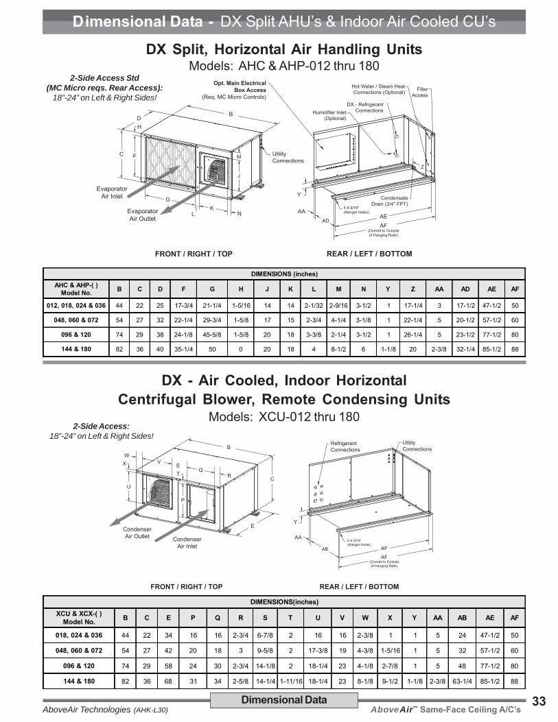
AboveAir™ Same-Face Ceiling A/C’sAboveAir Technologies (AHK-L30)33Dimensional Data
Dimensional Data - DX Split AHU’s & Indoor Air Cooled CU’s
DX Split, Horizontal Air Handling UnitsModels: AHC & AHP-012 thru 180
U
X
P
T
VQ
S
R
W
CondenserAir Outlet Condenser
Air Inlet
FRONT / RIGHT / TOP
UtilityConnections
Y
AB AE
AA
REAR / LEFT / BOTTOM
4 X 9/16"(Hanger Holes)
AF(Overall to Outsideof Hanging Rails)
RefrigerantConnectionsB
C
E
D
H
F
L
G
KN
M
J
C
B
Evaporator
Air Outlet
Evaporator
Air Inlet
FRONT / RIGHT / TOP
Utility
Connections
Y
ADAE
AA
Z
Condensate
Drain (3/4" FPT)
REAR / LEFT / BOTTOM
4 X 9/16"(Hanger Holes)
AF(Overall to Outsideof Hanging Rails)
DX - Refrigerant
ConnectionsHumidifier Inlet
(Optional)
Hot Water / Steam Heat
Connections (Optional)Filter
Access
Opt. Main Electrical
Box Access
(Req. MC Micro Controls)
DX - Air Cooled, Indoor HorizontalCentrifugal Blower, Remote Condensing Units
Models: XCU-012 thru 180
DIMENSIONS(inches)XCU & XCX-( )
Model No. B C E P Q R S T U V W X Y AA AB AE AF
018, 024 & 036 44 22 34 16 16 2-3/4 6-7/8 2 16 16 2-3/8 1 1 5 24 47-1/2 50
048, 060 & 072 54 27 42 20 18 3 9-5/8 2 17-3/8 19 4-3/8 1-5/16 1 5 32 57-1/2 60
096 & 120 74 29 58 24 30 2-3/4 14-1/8 2 18-1/4 23 4-1/8 2-7/8 1 5 48 77-1/2 80
144 & 180 82 36 68 31 34 2-5/8 14-1/4 1-11/16 18-1/4 23 8-1/8 9-1/2 1-1/8 2-3/8 63-1/4 85-1/2 88
2-Side Access Std(MC Micro reqs. Rear Access):
18”-24” on Left & Right Sides!
2-Side Access:18”-24” on Left & Right Sides!
DIMENSIONS (inches)AHC & AHP-( )
Model No. B C D F G H J K L M N Y Z AA AD AE AF
012, 018, 024 & 036 44 22 25 17-3/4 21-1/4 1-5/16 14 14 2-1/32 2-9/16 3-1/2 1 17-1/4 3 17-1/2 47-1/2 50
048, 060 & 072 54 27 32 22-1/4 29-3/4 1-5/8 17 15 2-3/4 4-1/4 3-1/8 1 22-1/4 5 20-1/2 57-1/2 60
096 & 120 74 29 38 24-1/8 45-5/8 1-5/8 20 18 3-3/8 2-1/4 3-1/2 1 26-1/4 5 23-1/2 77-1/2 80
144 & 180 82 36 40 35-1/4 50 0 20 18 4 8-1/2 6 1-1/8 20 2-3/8 32-1/4 85-1/2 88

AboveAir™ Same-Face Ceiling A/C’s AboveAir Technologies (AHK-L30)34 Dimensional Data
Dimensional Data - DX Remote Outdoor Air Cooled Heat Rejection1-5 Tons, Outdoor, DX - Air Cooled
Propeller Fan, Remote Condensing Units & CondensersModels: XPU & XP1-012 thru 120
REAR / LEFT / TOPFRONT / LEFT / TOP
A
1-1/2" Channel
Main Electric Box
RefrigerantConnections
BC
XPU & XP1-( )Model Size
Dimensions XPU & XP1-( )Model Size
DimensionsA B C A B C
XPU & XP1-012 & 018 25-5/16" 23-1/8" 23-1/8" XPU & XP1-048 35-3/4" 31-3/16 31-3/16"
XPU & XP1-024 28-11/16" 23-1/8" 23-1/8" XPU & XP1-060 28-15/16" 31-3/16 31-3/16"
XPU & XP1-030 31-3/16" 25-3/4" 25-3/4" XPU & XP1-072/120 35-1/2" 35-1/2" 41-1/2"
XPU & XP1-036 32-5/16" 31-3/16" 31-3/16"
Qty. one XPU condensing unit is provided per circuit:• AHC/P-072 units are provided w/ qty. 2 x XPU-036• AHC/P-096 units are provided w/ qty. 2 x XPU-048• AHC/P-120 units are provided w/ qty. 2 x XPU-060 or 1 x XPU-120D (consult facory for dimensional information)• AHC/P-144 units are provided w/ qty. 2 x XPU-072 or 1 x XPU-144D (consult facory for dimensional information)• AHC/P-180 units are provided w/ qty. 2 x XPU-090 or 1 x XPU-180D (consult facory for dimensional information)
98.25"
6"
Control PanelReturn
Bend Cover
42.75"
18.25"
96.0"1.13"
Lifting Holes1.5" Dia (Typ.)
45.0"48.0"
Remote Outdoor Propeller Fan, Air Cooled Condensers(for Models AEC & AEP-072D thru 180D DX-Evaps)
Models: WP1-108D, 132D & 156D
42.75"(Overall)
48.0"2.25"
18.25"45.0"48.5"
52.5"4.875”
Control Panel
Lifting Holes9/16" Dia (4)
9/16" Dia (4)Mounting Holes
Models: WP2-204D & 252D

AboveAir™ Same-Face Ceiling A/C’sAboveAir Technologies (AHK-L30)35
DX - Split DX Evap & Water/Glycol Self-ContainedModel: AEC/AEP, AWC/AWP & AGC/AGP-012 thru 180
(Also AWC/AWP & AGP/AGP-012/180-_-FE Free-Cooling Economizer)
H
F
L
GK
N
M
J
B
EvaporatorAir Outlet
EvaporatorAir Inlet
FRONT / RIGHT / TOP(Evaporator End)
UtilityConnections
EvaporatorSection
Condensing UnitSection
E
D
C
A
Y
AB
AC ADAE
AA
Z
CondensateDrain (3/4" FPT)
REAR / LEFT / BOTTOM(Condensing Unit End)
8 X 9/16"(Hanger Holes)
AF(Overall to Outsideof Hanging Rails)
DX - Evaporator & Water/Glycol Condenser
Connections
Humidifier Inlet(Optional)
Hot Water / Steam Heat orFree-Cool Connections
(Optional)
FilterAccess
Dimensional Data
Dimensional Data - DX Split Evap & Water/Glycol Cooled Self-Contained
DIMENSIONS(inches)
AEC/AEP &AWC/AWP_-( )
Model No.A B C D E F G H J K L
012, 018,024 & 036 45 44 22 25 20 17-3/4 21-1/4 1-5/16 14 14 2-1/32
048, 060 & 072 56 54 27 32 24 22-1/4 29-3/4 1-5/8 17 15 2-3/4
096 & 120 62 74 29 38 24 24-1/8 45-5/8 1-5/8 20 18 3-3/8
144 & 180 70 82 36 40 30 35-1/4 50 0 20 18 4
AEC/AEP &AWC/AWP_-( )
Model No.M N Y Z AA AB AC AD AE AF
012, 018,024 & 036 2-9/16 3-1/2 1-1/8 17-1/4 3 14 6 17-1/2 47-1/2 50-1/2
048, 060 & 072 4-1/4 3-1/8 1-1/8 22-1/4 3 18 8 20-1/2 57 1/2 60-1/2
096 & 120 2-1/4 3-1/2 1-1/8 26-1/4 3 18 8 23-1/2 77-1/2 80-1/2
144 & 180 8-1/2 6 1-1/8 20 2-3/8 25-1/4 4-3/4 32-1/4 85-1/2 88
Note:1) As standard, all 1-15 Ton Horizontal Water/Glycol Self-Contained systems ship from the factory as 1-piece units.
DX Water/Glycol Cooled systems are also available for split installation - see page 36 for details.
3-Side Access:18”-24” on Rear, Left & Right Sides!
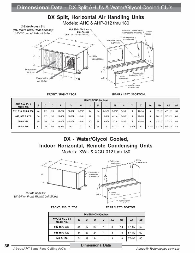
AboveAir™ Same-Face Ceiling A/C’s AboveAir Technologies (AHK-L30)36
D
H
F
L
G
KN
M
J
C
B
Evaporator
Air Outlet
Evaporator
Air Inlet
FRONT / RIGHT / TOP
Utility
Connections
Y
ADAE
AA
Z
Condensate
Drain (3/4" FPT)
REAR / LEFT / BOTTOM
4 X 9/16"(Hanger Holes)
AF(Overall to Outsideof Hanging Rails)
DX - Refrigerant
ConnectionsHumidifier Inlet
(Optional)
Hot Water / Steam Heat
Connections (Optional)Filter
Access
Opt. Main Electrical
Box Access
(Req. MC Micro Controls)
2-Side Access Std(MC Micro reqs. Rear Access):
18”-24” on Left & Right Sides!
Dimensional Data
Dimensional Data - DX Split AHU’s & Water/Glycol Cooled CU’s
B
Water/GlycolCondenserConnections
E
C
FRONT / RIGHT / TOP REAR / LEFT / BOTTOM
Y
ABAEAA
4 X 9/16"(Hanger Holes)
AF(Overall to Outsideof Hanging Rails)
RefrigerantConnections
UtilityConnections
DIMENSIONS(inches)XWU & XGU-( )
Model No. B C E Y AA AB AE AF
012 thru 036 44 22 20 1 3 14 47-1/2 50
048 thru 120 54 27 24 1 3 18 57-1/2 60
144 & 180 74 29 24 1 3 18 77-1/2 80
DX Split, Horizontal Air Handling UnitsModels: AHC & AHP-012 thru 180
DX - Water/Glycol Cooled,Indoor Horizontal, Remote Condensing Units
Models: XWU & XGU-012 thru 180
3-Side Access:18”-24” on Front, Right & Left Sides!
DIMENSIONS (inches)AHC & AHP-( )
Model No. B C D F G H J K L M N Y Z AA AD AE AF
012, 018, 024 & 036 44 22 25 17-3/4 21-1/4 1-5/16 14 14 2-1/32 2-9/16 3-1/2 1 17-1/4 3 17-1/2 47-1/2 50
048, 060 & 072 54 27 32 22-1/4 29-3/4 1-5/8 17 15 2-3/4 4-1/4 3-1/8 1 22-1/4 5 20-1/2 57-1/2 60
096 & 120 74 29 38 24-1/8 45-5/8 1-5/8 20 18 3-3/8 2-1/4 3-1/2 1 26-1/4 5 23-1/2 77-1/2 80
144 & 180 82 36 40 35-1/4 50 0 20 18 4 8-1/2 6 1-1/8 20 2-3/8 32-1/4 85-1/2 88

AboveAir™ Same-Face Ceiling A/C’sAboveAir Technologies (AHK-L30)37Dimensional Data
Dimensional Data - Chilled Water Air Handling Units (1-15 Tons)
Chilled Water, Horizontal Air Handling UnitsModels: ACC & ACP-012 thru 180
DIMENSIONS (inches)ACC & ACP-( )
Model No. B C D F G H J K L M N Y Z AA AD AE AF
012, 018, 024 & 036 44 22 25 17-3/4 21-1/4 1-5/16 14 14 2-1/32 2-9/16 3-1/2 1 17-1/4 3 17-1/2 47-1/2 50
048, 060 & 072 54 27 32 22-1/4 29-3/4 1-5/8 17 15 2-3/4 4-1/4 3-1/8 1 22-1/4 5 20-1/2 57-1/2 60
096 & 120 74 29 38 24-1/8 45-5/8 1-5/8 20 18 3-3/8 2-1/4 3-1/2 1 26-1/4 5 23-1/2 77-1/2 80
144 & 180 82 36 40 35-1/4 50 0 20 18 4 8-1/2 6 1-1/8 20 2-3/8 32-1/4 85-1/2 88
D
H
F
L
G
KN
M
J
C
B
Evaporator
Air Outlet
Evaporator
Air Inlet
FRONT / RIGHT / TOP
Utility
Connections
Y
ADAE
AA
Z
Condensate
Drain (3/4" FPT)
REAR / LEFT / BOTTOM
4 X 9/16"(Hanger Holes)
AF(Overall to Outsideof Hanging Rails)
Chilled Water
Connections
Hot Water / Steam Heat
Connections (Optional)
Filter
Access
Opt. Main Electrical
Box Access
(Req. MC Micro Controls)
2-Side Access Std(MC Micro reqs. Rear Access):
18”-24” on Left & Right Sides!

AboveAir™ Same-Face Ceiling A/C’s AboveAir Technologies (AHK-L30)38
Blank Page

AboveAir™ Same-Face Ceiling A/C’sAboveAir Technologies (AHK-L30)39Nomenclature / Ship Wts.
Supplemental Data - Model Nomenclature & Unit Weights
Model Nomenclature
Approximate Shipping Weights (lbs.)
TINUEZIS
EPYTLEDOM
P/CAAP/CHA UCX UPX
P/CGA&P/CWA&P/CWAEF-P/CGA
&UWXUGX
&CCAPCApavE dnoC
degakcaPmetsyS
pavE dnoCdegakcaP
metsyS
210 532 523 075 532 523 031 532 591 044 554 591 042
810 532 543 095 532 543 531 532 512 064 574 512 042
420 052 553 016 052 553 531 052 512 074 594 512 542
630 052 063 026 052 063 041 052 522 084 505 522 542
840 043 574 028 043 574 002 043 092 046 086 092 043
060 043 515 568 043 515 012 043 523 576 517 523 043
270 073 585 069 073 585 2x041 073 573 547 597 573 063
690 583 095 589 583 095 2x002 583 004 597 548 004 073
021 055 598 574,1 055 598 2x012 055 535 501,1 571,1 535 055
441 065 049 515,1 065 049 2x524 065 075 541,1 512,1 075 055
081 065 049 515,1 065 049 2x054 065 085 551,1 522,1 085 055
Notes:1) AAC/P, AWC/P & AGC/P-012/120 systems ship from the factory as a 1-piece, packaged unit as a standard.
AAC/P-144/180 systems ship from the factory split for field rigging purposes.
a: A - AboveAir™ Horizontal HK Series
b: A - DX, Air CooledC - Chilled WaterE - DX, Evaporator with CompressorG - DX, Glycol CooledH - DX, Air Handling UnitW - DX, Water Cooled
c: C - ComfortCOOL™ Series (Standard CFM)P - PrecisionCOOL™ Series (Optional CFM)
d: D - Dual Circuit/Compressor DX System
e: 012 = 1 Ton; 018 = 1.5 Tons; 024 = 2.0 Tons; 030 = 2.5 Tons;036 = 3.0 Tons; 048 = 4.0 Tons; 060 = 5.0 Tons; 072 = 6.0 Tons;096 = 8.0 Tons; 120 = 10.0 Tons; 144 = 12.0 Tons; 180 = 15.0 Tons
f: 1 - 208-230V / 1 Ph / 60 Hz3 - 208-230V / 3 Ph / 60 Hz4 - 460-480V / 3 Ph / 60 Hz5 - 575V / 3 Ph / 60 Hz7 - 277V / 1 Ph / 60 Hz
g: 00 - No HeatE1 - Electric Heat 1-StageE2 - Electric Heat 2-StagesES - SCR Fired Electric HeatHE - Heat Pump with Auxiliary Electric HeatHG - Hot Gas ReheatHP - Heat Pump w/o Auxiliary Electric HeatHW - Hot Water HeatES - SCR Fired Electric HeatST - Steam Heat
h: 0 - No HumidifierH - Electrode Canister Humidifier
i: 00 - No EconomizerAE - Air Side EconomizerDC - Dual Cool / Alternate Water SourceFE - Water/Glycol Side Free Cooling Economizer
j: 00 - NoneOA - 100% Outside-Air System
a: X - Remote Condenser or Condensing Unit (wrap-around coil type)W - Remote Condenser or Condensing Unit (slab coil type)
b: C - DX, Air Cooled, Centrifugal Blower TypeG - DX, Glycol CooledP - DX, Air Cooled, Propeller Fan TypeW - DX, Water Cooled
c: U - Outdoor DX Condensing UnitX - Indoor DX Condenser1 - Single-Circuit Condenser2 - Dual-Circuit Condenser
d: D - Dual Circuit/Compressor DX System
e: 012 = 1 Ton; 018 = 1.5 Tons; 024 = 2.0 Tons; 036 = 3.0 Tons;048 = 4.0 Tons; 060 = 5.0 Tons; 072 = 6.0 Tons; 090 = 7.5 Tons;096 = 8.0 Tons; 120 = 10.0 Tons; 144 = 12.0 Tons; 180 = 15.0 Tons
f: 1 - 208-230V / 1 Ph / 60 Hz3 - 208-230V / 3 Ph / 60 Hz4 - 460-480V / 3 Ph / 60 Hz5 - 575V / 3 Ph / 60 Hz7 - 277V / 1 Ph / 60 Hz
g: 00 - NoneHP - Heat Pump Option
h: 00 - NoneOA - 100% Outside-Air System
i: A - Indoor MountedB - Outdoor Mounted
A G C - 120 D - 4 - E1 H - FE - 00a b c - d e - f - g h - i - j
Packaged Systems & Split Evaporators Remote Condensing Units
X C U - 120 D - 4 - 00 - 00a b c - d e - f - g - h

AboveAir™ Same-Face Ceiling A/C’s AboveAir Technologies (AHK-L30)40
I n n o v a t i v e H VA C S o l u t i o n s
5179 Mountville RoadFrederick, Maryland 21703, U.S.A.
Phone: 301-874-1130, Facsimile: 301-874-1131
Email: [email protected]
Copyright 01/15Form: AHK-L30
Specifications are subjectto change without notice.
www.aaaaabobobobobovvvvveaireaireaireaireair.com
Comfort - Packaged & SplitVertical Floor Mounted
Air Conditioners(1 to 45 Tons)
VK-MissionCriticalTM - Up-Flow & Down-FlowVertical Floor Mounted Computer Room
Air Conditioners(1 to 30 Tons)
Remote Air CooledCondensers, Condensing Units &
Glycol Drycoolers(1 to 180 Tons of THR)
Precision - Vertical Floor ConsoleMounted Air Conditioners
(1 to 30 Tons)
High-Static BD “Ducted”Ceiling Mounted A/C’s
(1 to 30 Tons)
2x4 “Spot-Cool & Ducted”Ceiling Mounted A/C’s
(1 to 3 Tons)
Single, Dual & TriplexGlycol Pump Packages
(1/2 to 50 HP)
Ceiling Ceiling Ceiling Ceiling Ceiling Air ConditionerAir ConditionerAir ConditionerAir ConditionerAir ConditionersssssSpotSpotSpotSpotSpotCoolCoolCoolCoolCool
™ - 2x4 T-Bar “Spot-Cool & Ducted”Comfort & Precision Ceiling Mounted A/C’s
HKHKHKHKHK ™ HorizHorizHorizHorizHorizontalontalontalontalontal - Hi-Static Ducted Comfort &
Precision Ceiling Mounted A/C’s
HKHKHKHKHK-O-O-O-O-OAAAAA ™ - Horizontal Up to 100% DOAS High-
Percentage Outside Air Ceiling Mounted A/C’s
FFFFFloor loor loor loor loor Air ConditionerAir ConditionerAir ConditionerAir ConditionerAir ConditionersssssMissionMissionMissionMissionMissionCriticalCriticalCriticalCriticalCritical
™ - Precision Vertical FloorMounted Computer Room A/C’s
VKVKVKVKVK™ VVVVVerererererticalticalticalticaltical - SCAV, Vertical Floor MountedSelf-Contained & Split Comfort Constant Air Volumeand Variable Air Volume (VAV) A/C’s & Heat Pumps
VKVKVKVKVK-O-O-O-O-OAAAAA ™ - Vertical Up to 100% DOAS High-
Percentage Outside Air Vertical Floor Mounted A/C’s
VKVKVKVKVK™ ConsoleConsoleConsoleConsoleConsole - Vertical Floor Console MountedSelf-Contained & Split A/C’s & Heat Pumps
RRRRRemote Heaemote Heaemote Heaemote Heaemote Heat Rt Rt Rt Rt Rejectionejectionejectionejectionejection
FluidFluidFluidFluidFluidCoolCoolCoolCoolCool ™ - Indoor & Outdoor Remote Glycol
Drycoolers
PumpPumpPumpPumpPumpAllAllAllAllAll ™ - Single, Dual & Triplex Standard &
Variable (VFD) Speed Glycol Pump Packages


![POMPA AIR ENERGI TERMAL MENGGUNAKAN EVAPORATOR …repository.usd.ac.id/30162/2/075214018_Full[1].pdf · evaporator, (2) kompor, dan (3) tuning pipe (pipa osilasi). Pompa air energi](https://img.pdfslide.net/doc/110x75/609a62f88f15cc719148b947/pompa-air-energi-termal-menggunakan-evaporator-1pdf-evaporator-2-kompor.jpg)


![POMPA AIR PULSE JET ENERGI TERMAL DENGAN EVAPORATOR …repository.usd.ac.id/30015/2/065214032_full[1].pdf · POMPA AIR PULSE JET ENERGI TERMAL DENGAN EVAPORATOR MIRING Tugas akhir](https://img.pdfslide.net/doc/110x75/5f4e5288bc3bd80b8e5e8d6b/pompa-air-pulse-jet-energi-termal-dengan-evaporator-1pdf-pompa-air-pulse-jet.jpg)
![POMPA AIR ENERGI TERMAL MENGGUNAKAN EVAPORATOR …repository.usd.ac.id/30166/2/075214023_Full[1].pdf · evaporator 70 cc). Selain melakukan pengujian, penelitian juga membandingkan](https://img.pdfslide.net/doc/110x75/608012dae637467261300858/pompa-air-energi-termal-menggunakan-evaporator-1pdf-evaporator-70-cc-selain.jpg)