Embed Size (px)
Citation preview

Racetrack Flashlight Assembly Instruction
Manual
ENGR 480 ManufacturingSpring 2012
Produced by Team Bernet:Aaron BoydMark Bernet
Brian Zimmerly
Team Bernet - Manufacturing Project - Spring 2012
1
Table of Contents
Instructions--------------------------------------------------------------4
Starting-----------------------------------------------------------------5
Nose--------------------------------------------------------------------6
Nose O-Ring and Lens Assembly----------------------------------------------------------------8
Washer and Magnetic Ring--------------------------------------------------------------------9
Main O-Ring-------------------------------------------------------------------11
Battery and Body Tube-------------------------------------------------------------------12
Known Problems---------------------------------------------------------15
Future Improvements-----------------------------------------------------------16
CNC Code--------------------------------------------------------------17
Team Bernet - Manufacturing Project - Spring 2012
2
List of Figures:
Figure(1) Racetrack Assembly-----------------------------------------4
Figure(2) Nose Assembly station, view 1--------------------------------------6
Figure(3) Nose Assembly station, view 2--------------------------------7
Figure(4) Lens and Nose O-ring assembly station.------------------------8
Figure(5) Washer and Magnetic ring assembly station (view 1)--------------9
Figure(6) Washer and Magnetic ring assembly station (view 2)-------------10
Figure(7) Main O-Ring assembly station-------------------------------11
Figure(8) Battery and Body-Tube assembly station (view 1)---------------12
Figure(9) Battery and Body-Tube assembly station (view 2)---------------13
Team Bernet - Manufacturing Project - Spring 2012
3

Racetrack Assembly
Figure(1) Racetrack Assembly
It is a modular assembly that can be easily and rapidly reconfigured to support different operations. This system is more simple than most, because the carts require no modification and are universal. All the all complexity is contain within the individual stations.
This is the 2nd year that the racetrack assembly has been used in this class and the entire project was redesigned from scratch, little of last year’s tooling survived.
The stations consist of an X, Y and Z axis that can be operated with stepper motors. Each station is run off of Linux CNC and its own computer. This allows the system to continue to run in an old configuration while a new station is added. The system is powered my Pneumatic cylinders and rams as well as a voltage converter that allows for a computer interface.
Team Bernet - Manufacturing Project - Spring 2012
4

Instructions
Starting
In order to get the system powered up and running two things need to be started. First the pneumatics need to be pressurized and second the computers need to be powered up and booted with Linux and Linux CNC.
To prepare the pneumatics you must first plug the orange hose into the wall until you hear a faint hissing noise. This means that the lines and cylinders are charged and ready to rock. However make sure that the pressure in the lines is around 32 psi. This can be adjusted by turning the valves located in the solenoids located at the base of the tables.
Next the three computers need to be booted and you need to ensure that the voltage converters are plugged in and turned one. The voltage converters power the stepper motors and allow for conversion of the signals that will be read by the computers for Linux CNC. Then boot up Linux CNC on all the computers and make sure the three programs are loaded. Each station must be run by a separate computer so make sure that they are all powered on.
Team Bernet - Manufacturing Project - Spring 2012
5
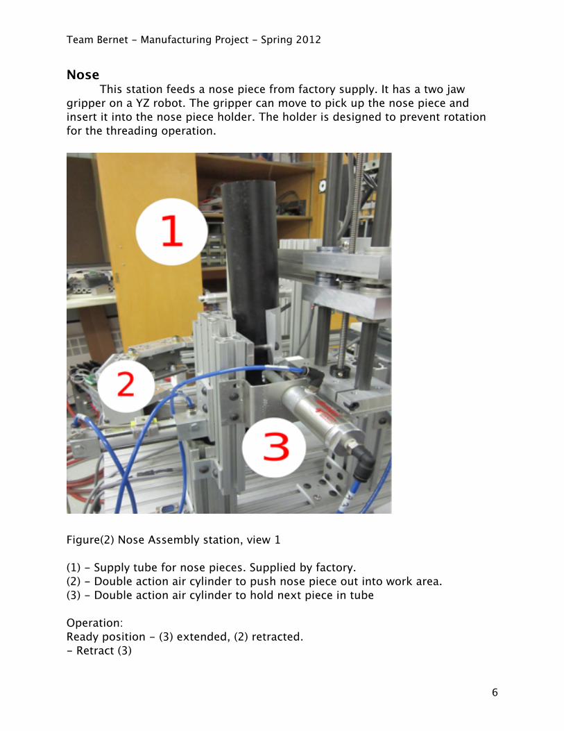
Nose This station feeds a nose piece from factory supply. It has a two jaw gripper on a YZ robot. The gripper can move to pick up the nose piece and insert it into the nose piece holder. The holder is designed to prevent rotation for the threading operation.
Figure(2) Nose Assembly station, view 1
(1) - Supply tube for nose pieces. Supplied by factory.(2) - Double action air cylinder to push nose piece out into work area.(3) - Double action air cylinder to hold next piece in tube
Operation: Ready position - (3) extended, (2) retracted.- Retract (3)
Team Bernet - Manufacturing Project - Spring 2012
6
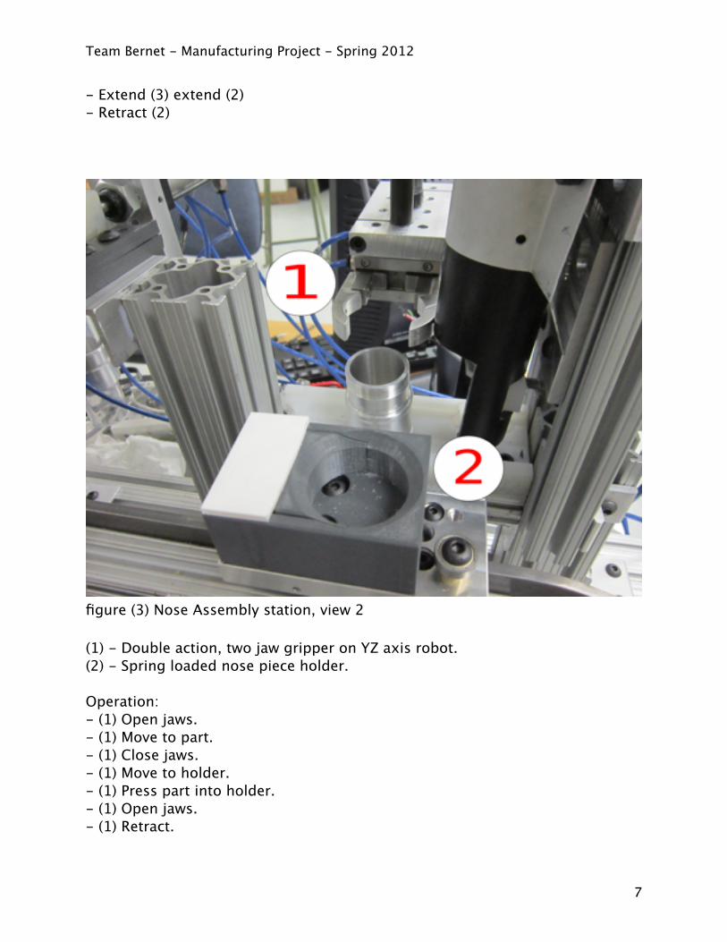
- Extend (3) extend (2)- Retract (2)
figure (3) Nose Assembly station, view 2
(1) - Double action, two jaw gripper on YZ axis robot.(2) - Spring loaded nose piece holder.
Operation:- (1) Open jaws.- (1) Move to part.- (1) Close jaws.- (1) Move to holder.- (1) Press part into holder.- (1) Open jaws.- (1) Retract.
Team Bernet - Manufacturing Project - Spring 2012
7
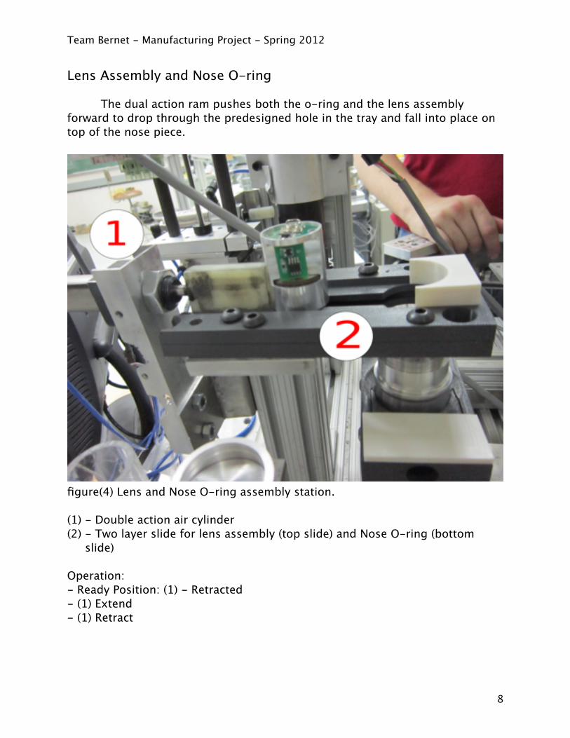
Lens Assembly and Nose O-ring
The dual action ram pushes both the o-ring and the lens assembly forward to drop through the predesigned hole in the tray and fall into place on top of the nose piece.
figure(4) Lens and Nose O-ring assembly station.
(1) - Double action air cylinder(2) - Two layer slide for lens assembly (top slide) and Nose O-ring (bottom
slide)
Operation:- Ready Position: (1) - Retracted - (1) Extend- (1) Retract
Team Bernet - Manufacturing Project - Spring 2012
8
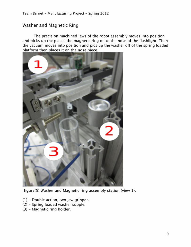
Washer and Magnetic Ring
The precision machined jaws of the robot assembly moves into position and picks up the places the magnetic ring on to the nose of the flashlight. Then the vacuum moves into position and pics up the washer off of the spring loaded platform then places it on the nose piece.
figure(5) Washer and Magnetic ring assembly station (view 1).
(1) - Double action, two jaw gripper.(2) - Spring loaded washer supply.(3) - Magnetic ring holder.
Team Bernet - Manufacturing Project - Spring 2012
9

figure(6) Washer and Magnetic ring assembly station (view 2).
(1) - Vacuum washer lifter(2) - Spring loaded washer supply
Operation:- (1) Open jaws- (1) Move to part- (1) Close jaws- (1) Move to assembly- (1) Open jaws- (4) Move to part- (4) Vacuum on- (4) Move to assembly- (4) Vacuum off- (4) Retract
Team Bernet - Manufacturing Project - Spring 2012
10
4
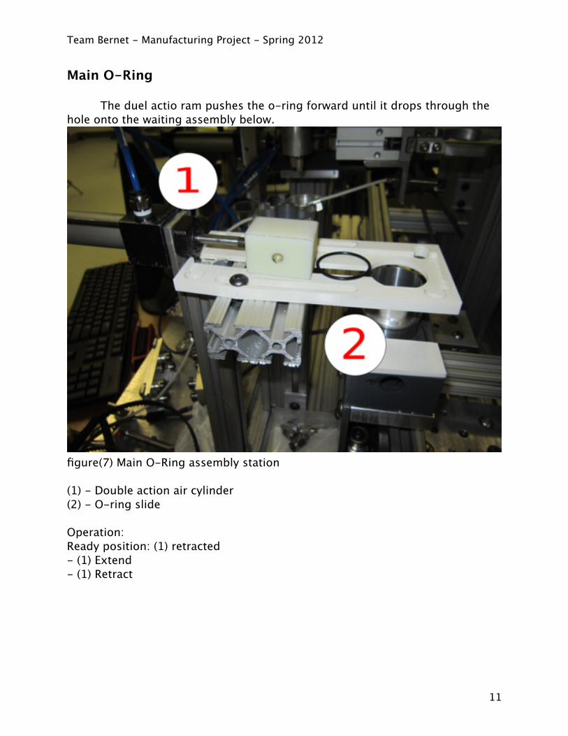
Main O-Ring
The duel actio ram pushes the o-ring forward until it drops through the hole onto the waiting assembly below.
figure(7) Main O-Ring assembly station
(1) - Double action air cylinder(2) - O-ring slide
Operation:Ready position: (1) retracted- (1) Extend- (1) Retract
Team Bernet - Manufacturing Project - Spring 2012
11
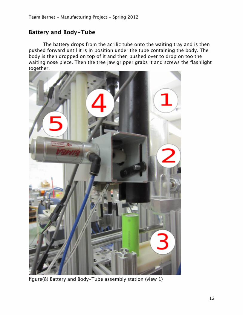
Battery and Body-Tube The battery drops from the acrilic tube onto the waiting tray and is then pushed forward until it is in position under the tube containing the body. The body is then dropped on top of it and then pushed over to drop on too the waiting nose piece. Then the tree jaw gripper grabs it and screws the flashlight together.
figure(8) Battery and Body-Tube assembly station (view 1)
Team Bernet - Manufacturing Project - Spring 2012
12
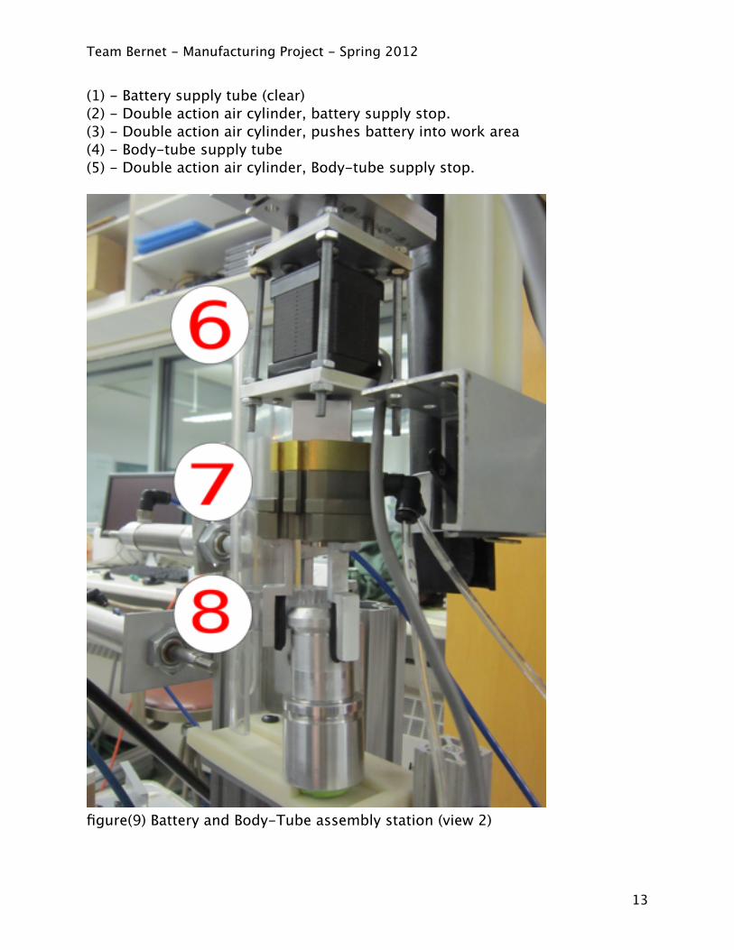
(1) - Battery supply tube (clear)(2) - Double action air cylinder, battery supply stop.(3) - Double action air cylinder, pushes battery into work area(4) - Body-tube supply tube(5) - Double action air cylinder, Body-tube supply stop.
figure(9) Battery and Body-Tube assembly station (view 2)
Team Bernet - Manufacturing Project - Spring 2012
13

(6) - Stepper motor for threading attached to YZ robot(7) - Double action, 3 jaw gripper(8) - Friction grips.
Operation:Ready Position: (2) Extend (3) Retract (5) Extend- (2) retarct- (2) extend, (3) extend- (5) retract- (3) retract- (5) extend: During this cycle a body-tube should fall from (4) and land over
top of the battery.- (7) Open jaws- (6,7) Move to part- (7) Close jaws- (6,7) Slide to assembly- (6) threading operation. Clearance is allowed in this assembly to accomodate
linear travel as a result of threading.- (7) open jaws
Team Bernet - Manufacturing Project - Spring 2012
14
Known Problems:
- At station 2 the o-rings sometimes stick in the whole in the lens and o-ring tray and the cylinder leaks.
- Station 3 the magnetic sensor is misallined,the ring holder and washer holder have limited capaticy, the y,z robot does not have a belt clamp and so has nomotion in the y direction.
- Station 4 the o-ring sticks in the tray while dropping through to the top of the nose piece.
- station 5 the rods forthe x/y robot the rods are slipping, missing a belt clamp like station 3, the hoses for the three jaw gripper get caught was it spins, and sometimes the o-ring gets nocked while the jaws spin.
Team Bernet - Manufacturing Project - Spring 2012
15
Future Improvements
- Station 2 create a better tray, get a new air clynder and new end for the ram, better way to reload o-rings in the tray.
- Station 3 align the magnetic probe, larger capacity holders, and add a belt, grab the washer and ring in a single movement.
- Station 4 new tray and new end for the ram.- Station 5 needs a coplete make over to make it function more effiecntly, also
hold the O-ring on the nose piece.
Team Bernet - Manufacturing Project - Spring 2012
16
Linux CNC Code
Station 1M64 P1 Hold Part in tubeM64 P0 Push out lowest partM65 P0 Retract CylinderM65 P1 Allow next part to fall
M64 p2 Open Grabber (to make sure its open)G01 Y3.77 F60
G01 Z-1.0 F60M65 p2 Close GrabberG01 Z10.0 F60G01 Y7.37 F60G01 Z5.0 F60M64 p2 Open GrabberG01 Z10.0 F60G01 Y3.77 F60G01 Z2.0 F60
Station 2 m64 p3m65 p3
Station 3
Station 4m64 p2m65 p2
Station 5# gcode program# setup G64 p2 and G64 p3 close tubes holding battery and tubem65 p2 Drop Batterym64 p1 Push Battery m65 p3 Drop Tubem65 p1 retract battery pusher ( order on purpose ^)m64 p2 try to force p1 to retract
g01 z-4.7 f60
Team Bernet - Manufacturing Project - Spring 2012
17
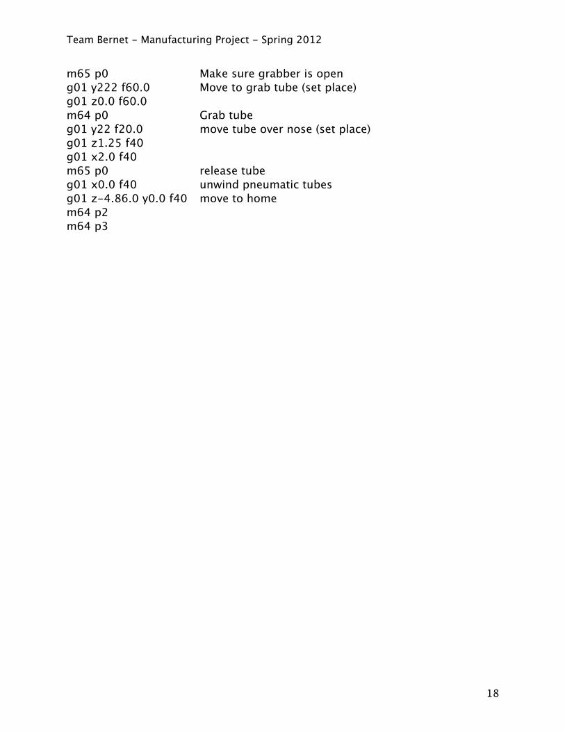
m65 p0 Make sure grabber is openg01 y222 f60.0 Move to grab tube (set place)g01 z0.0 f60.0 m64 p0 Grab tubeg01 y22 f20.0 move tube over nose (set place)g01 z1.25 f40g01 x2.0 f40m65 p0 release tubeg01 x0.0 f40 unwind pneumatic tubesg01 z-4.86.0 y0.0 f40 move to homem64 p2m64 p3
Team Bernet - Manufacturing Project - Spring 2012
18