Embed Size (px)
Citation preview

Rack Console with KVM Switch
RACKCONS1708RACKCONS1916
Instruction Manual
Actual product may vary from photo
17” LCD Rackmount Console with 8 Port KVM19” LCD Rackmount Console with 16 Port KVM

FFCCCC CCoommpplliiaannccee SSttaatteemmeennttThis equipment has been tested and found to comply with the limits for a Class B digitaldevice, pursuant to part 15 of the FCC Rules. These limits are designed to providereasonable protection against harmful interference in a residential installation. Thisequipment generates, uses and can radiate radio frequency energy and, if not installedand used in accordance with the instructions, may cause harmful interference to radiocommunications. However, there is no guarantee that interference will not occur in aparticular installation. If this equipment does cause harmful interference to radio ortelevision reception, which can be determined by turning the equipment off and on, theuser is encouraged to try to correct the interference by one or more of the followingmeasures:
• Reorient or relocate the receiving antenna.
• Increase the separation between the equipment and receiver.
• Connect the equipment into an outlet on a circuit different from that to which the receiver is connected.
• Consult the dealer or an experienced radio/TV technician for help.
UUssee ooff TTrraaddeemmaarrkkss,, RReeggiisstteerreedd TTrraaddeemmaarrkkss,, aannddootthheerr PPrrootteecctteedd NNaammeess aanndd SSyymmbboollssThis manual may make reference to trademarks, registered trademarks, and otherprotected names and/or symbols of third-party companies not related in any way toStarTech.com. Where they occur these references are for illustrative purposes only anddo not represent an endorsement of a product or service by StarTech.com, or anendorsement of the product(s) to which this manual applies by the third-party company inquestion. Regardless of any direct acknowledgement elsewhere in the body of thisdocument, StarTech.com hereby acknowledges that all trademarks, registeredtrademarks, service marks, and other protected names and/or symbols contained in thismanual and related documents are the property of their respective holders.

Instruction Manual
i
TTaabbllee ooff CCoonntteennttss
Introduction . . . . . . . . . . . . . . . . . . . . . . . . . . . . . . . . . . . . . . . . . . . . . . . . . . . . .1Features . . . . . . . . . . . . . . . . . . . . . . . . . . . . . . . . . . . . . . . . . . . . . . . .1
Before You Begin . . . . . . . . . . . . . . . . . . . . . . . . . . . . . . . . . . . . . . . . . . . . . . . . .1Package Contents . . . . . . . . . . . . . . . . . . . . . . . . . . . . . . . . . . . . . . . .1Accessory Products from StarTech.com . . . . . . . . . . . . . . . . . . . . . . .1
Installation and usage . . . . . . . . . . . . . . . . . . . . . . . . . . . . . . . . . . . . . . . . . . . .3Hardware kit contents . . . . . . . . . . . . . . . . . . . . . . . . . . . . . . . . . . . . . .3Mounting the Console . . . . . . . . . . . . . . . . . . . . . . . . . . . . . . . . . . . . .4Connecting the Console/Module . . . . . . . . . . . . . . . . . . . . . . . . . . . . .6Cascade Configuration . . . . . . . . . . . . . . . . . . . . . . . . . . . . . . . . . . . . .8Turning on the console . . . . . . . . . . . . . . . . . . . . . . . . . . . . . . . . . . . . .8Configuring display settings . . . . . . . . . . . . . . . . . . . . . . . . . . . . . . . . .8Testing the console . . . . . . . . . . . . . . . . . . . . . . . . . . . . . . . . . . . . . . . .9Panel controls and OSD functions . . . . . . . . . . . . . . . . . . . . . . . . . . . .9Auto tune . . . . . . . . . . . . . . . . . . . . . . . . . . . . . . . . . . . . . . . . . . . . . .10Input Source . . . . . . . . . . . . . . . . . . . . . . . . . . . . . . . . . . . . . . . . . . . .10Brightness . . . . . . . . . . . . . . . . . . . . . . . . . . . . . . . . . . . . . . . . . . . . . .10Contrast . . . . . . . . . . . . . . . . . . . . . . . . . . . . . . . . . . . . . . . . . . . . . . .10Color . . . . . . . . . . . . . . . . . . . . . . . . . . . . . . . . . . . . . . . . . . . . . . . . . .11Position . . . . . . . . . . . . . . . . . . . . . . . . . . . . . . . . . . . . . . . . . . . . . . . .11Language . . . . . . . . . . . . . . . . . . . . . . . . . . . . . . . . . . . . . . . . . . . . . .12Recall . . . . . . . . . . . . . . . . . . . . . . . . . . . . . . . . . . . . . . . . . . . . . . . . .12Exit . . . . . . . . . . . . . . . . . . . . . . . . . . . . . . . . . . . . . . . . . . . . . . . . . . .12
Module Operation . . . . . . . . . . . . . . . . . . . . . . . . . . . . . . . . . . . . . . . . . . . . . . .13Push Button Selection . . . . . . . . . . . . . . . . . . . . . . . . . . . . . . . . . . . .13Hot-key commands . . . . . . . . . . . . . . . . . . . . . . . . . . . . . . . . . . . . . .16
Specifications . . . . . . . . . . . . . . . . . . . . . . . . . . . . . . . . . . . . . . . . . . . . . . . . . .19
Technical Support . . . . . . . . . . . . . . . . . . . . . . . . . . . . . . . . . . . . . . . . . . . . . . .20
Warranty Information . . . . . . . . . . . . . . . . . . . . . . . . . . . . . . . . . . . . . . . . . . . .20

Instruction Manual
1
Thank you for purchasing a StarTech.com LCD Rack Console with KVM. This productallows you to manage multiple computers using an integrated keyboard, mouse, and TFTscreen that slides into a compact 1U of rack space when not in use.
IInnttrroodduuccttiioonn
Features
BBeeffoorree YYoouu BBeeggiinn
• On Screen Display (OSD)
• Durable design
• Compatible with PC, Mac and Sun servers and systems
• Cascadable design
• Hot-pluggable
• Security features, including port locking and auto scan
• Login authentication restricts access to authorized users
• 1U LCD Rack Console Drawer (1)
Package Contents
• 1U Multi-Platform KVM Switch (1)
• Console Cable Kit (1)
• Mounting Rails - Set (1)
This package should contain:
• Power Adapter (1)
Accessory Products from StarTech.comTo simplify connections between your new Rack Console/KVM Switch and the computersyou wish to control, contact your local StarTech.com dealer or visit www.startech.com forcables or other accessories:
SVSERIALADSerial Mouse Adapter for SVxx31 StarView KVM Switches
USB2PS2USB to PS2 Keyboard and Mouse Converter
• Mounting Brackets

Instruction Manual
2
SV125Sun to PS/2 Keyboard/Mouse Converter
SVECONUS1010 ft Ultra-Thin USB 2-in-1 KVM Cable
SVECONUS1515 ft Ultra-Thin USB 2-in-1 KVM Cable
SVECONUS66 ft Ultra-Thin USB 2-in-1 KVM Cable
SVECON106 ft. IEEE-1394 FireWire Cable 6-pin to 6-pin
SVECON1515 ft Ultra-Thin PS/2 3-in-1 KVM Cable
SVECON2525 ft Ultra-Thin PS/2 3-in-1 KVM Cable
SVECON3535 ft Ultra-Thin PS/2 3-in-1 KVM Cable
SVECON5050 ft Ultra-Thin PS/2 3-in-1 KVM Cable

Instruction Manual
3
IInnssttaallllaattiioonn aanndd uussaaggee
Please note: RACKCONS1708/RACKCONS1916 is comprised of two distinctcomponents - a Rackmountable Console and a Rackmountable KVM Module, asillustrated below. The two devices are attached via a Centronics connector on the Rearpanel of the Console and similarly the front panel of the Module.
Hardware kit contents
Side Rails with front and rearbrackets (2) Keys (2)
Screw kit
Front Panel
**16-port model shown
Console
Rear Panel
Module
Front view, open
Mounting Brackets
Instruction Manual
4
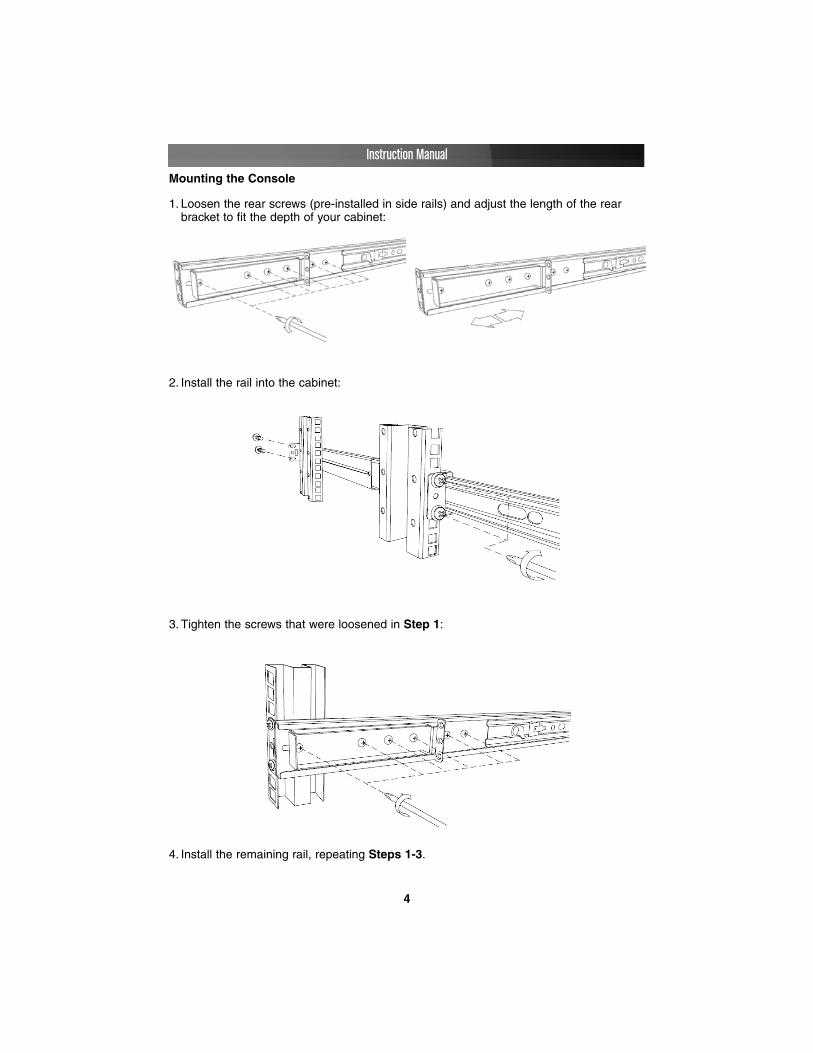
3. Tighten the screws that were loosened in Step 1:
2. Install the rail into the cabinet:
Mounting the Console
1. Loosen the rear screws (pre-installed in side rails) and adjust the length of the rear bracket to fit the depth of your cabinet:
4. Install the remaining rail, repeating Steps 1-3.

Instruction Manual
5
7. Install three screws on each side of the console:
6. Unlock the console, and pull the left and right rail-lock switches towards you simultaneously, and hold them in this position while pushing the console into the cabinet:
Rail Lock Switch
6. Gently, but firmly insert the Console (with Module attached) into the left and right rails:
5. Slide the Module onto the Console side rails, connecting the Module and Console using the male Centronics connector provided by the Console, and the female Centronics connector provided by the Module. Ensure the connection is secure, and that the module is firmly seated within the Console side rails.
Lock
Unlock

Instruction Manual
6
Connecting the Console/Module
To connect the KVM Console/Module to a computer, perform the following steps:
8. Installation is now complete:
1. Remove the four screws from both sides of the KVM console. Be sure to retain these screws for the next installation step.
2. Attach the mounting brackets to both sides of the KVM console, using the screws removed in step 1.

Instruction Manual
7
3. From the rear of the cabinet, slide the KVM console onto the mounting rails.
4. Install one screw on each side of the console (as depicted below).
Connecting computers to the module
Attach each of your managed computers to your StarView KVM console’s PC ports using ultra-thin KVM cables. The Module is capable of using either 2-in-1 USB or 3-in-1PS/2 cables. Use the cables to connect one of the PC ports on the back of the switch tothe computer's keyboard, mouse, and video ports. Note: These instructions are for asingle KVM switch only.
Following this, plug the 12V DC power adapter into the power port on the KVM module,and turn on the computers that will be controlled by the console.
Note: After the initial power up, you can hot-plug additional computers or slave KVMswitches without having to power down your KVM

Turning on the console
Make sure all cables and the power cord are connected properly. Grasp the handle ofthe drawer, pull the panel forward and up, then press the pushbutton in the top right handcorner to enable the TFT screen.
The LED located to the left of the monitor panel should turn from orange to green,verifying that the unit is operational.
Configuring display settings
After connecting the drawer and turning on your computer, you may need to configureone or more of the following display settings to allow the computer to display at theconsole’s native resolution. See Specifications for the correct resolution mode for yourmodel.
• Display mode (also called desktop area or video resolution)
• Refresh rate (also called vertical scan rate or vertical sync)
• Color depth (also called color palette or number of colors)
Each video card has several controls that allow you to adjust the display settings,however, the software and driver for each video card is unique. In most cases, you canadjust these settings using a program or utility provided by the manufacturer of the videocard. Most video cards use the Windows Display Properties control panel to configurethe display. To open the Windows Display Properties, click the right mouse button in ablank area of the Windows desktop and then select Properties. The Settings tab usuallylets you change the Color Palette and the Desktop Area (X by Y pixel resolution).
Some video cards integrate additional features into the Windows Display Propertiescontrol panel giving you extra setup options that are flexible and easy to use. For
Instruction Manual
8
Cascade Configuration
You can connect a second level of KVMs to one or more of your Master KVM console’sPC ports. The KVM switches connected to the Master console are known as Slaves.Once connected, the KVM switches will automatically configure themselves as eitherMasters or Slaves. You can only connect an equal or “smaller” KVM to the Master KVM.For example, a 16-port Master KVM switch can have both 16-port and 8-port slaves. An8-port Master KVM switch can only have 8-port (or fewer) KVM slaves.
The 8-port KVM can support 64 PCs, with 8 x 8-port Slave KVMs, each connected to 8PCs. The 16-port KVM can support 136 computers, with 8 16-port Slave KVMs, eachconnected to 16 computers. The Slave KVM’s must be connected to the 1~8 ports, notthe A~H ports.
To cascade your KVMs, use a 3-in-1 PS/2 KVM cable to connect one of your Masterswitch’s PC ports to the Slave switch’s console ports. When turning on your cascadedswitches, turn on the Master switch before turning on any of the others.

Instruction Manual
9
example, the control panel may include an Advanced Properties button, an Adjustmenttab, or a Refresh tab for changing other settings. Other video cards have a separateutility for setting display properties.
Whenever you change the resolution, color, or refresh rate, the image size, position, orshape may change. This behavior is normal. You can readjust the image using themonitor on-screen controls. For more information on the monitor on-screen controls, referto Panel controls and OSD functions. For more information on configuring the displaysettings, please refer to the manual that accompanied your video card.
Testing the console
To test that the console is working properly, perform the following steps:
1. Power up the LCD Rack drawer, and then turn on your computer.
2. Make sure the video image is centered within the screen area. Use the OSD controls to adjust the image (see Panel controls and OSD functions) or press the Autobutton on the right hand side of the monitor.
Note: You can adjust the horizontal and vertical position, contrast, and brightness to better suit your video card and your personal preference.
Before you begin, make sure that power to all of the devices you will be connecting to theconsole have been turned off. To prevent damage to your installation due to groundpotential difference, make sure that all of the devices being installed are properlygrounded. Once all peripherals have been connected, please power them on.
Panel controls and OSD functions
The following controls are located on the console monitor:
Controls Descriptions
Soft power on/off. Adjacent LED is lit when on
Auto Auto-synchronize and scale down display to any valid factory preset timings
Up Press to scroll to the function you want to adjust.
Down Press to scroll to the function you want to adjust.
Menu To access the main menu. This button also acts as the Enter button.
Instruction Manual
10
Auto tune
Press the Auto tune button. The panel will adjust the display size automatically and alsotune the panel to its optimized state.
Input Source
1. Press the Menu button.
2. Use the Down and Up buttons to scroll.
3. Press the Menu button to enter, and you will see: VGA/DVI
4. Use the Down and Up buttons to select the input signal source.
5. Press the Menu button to save your selection.
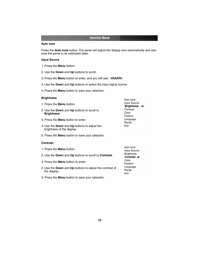
Brightness
1. Press the Menu button.
2. Use the Down and Up buttons to scroll to Brightness.
3. Press the Menu button to enter.
4. Use the Down and Up buttons to adjust the brightness of the display.
5. Press the Menu button to save your selection.
Auto tuneInput Source
ContrastColorPositionLanguageRecallExit
Brightness
Contrast
1. Press the Menu button.
2. Use the Down and Up buttons to scroll to Contrast.
3. Press the Menu button to enter.
2. Use the Down and Up buttons to adjust the contrast of the display.
3. Press the Menu button to save your selection.
Auto tuneInput SourceBrightness
ColorPositionLanguageRecallExit
Contrast

Instruction Manual
11
Color
1. Press the Menu button.
2. Use the Down and Up button to scroll.
3. Highlight Color, and press the Menu button to enter, which will launch the following screen:
4. Use the Down and Up buttons to adjust the contrast of the display.
5. Press the Menu button to save your selection.
Icon Description9300°K To set CIE coordinates at 9300°K color
7500°K To set CIE coordinates at 7500°K color
6500°K To set CIE coordinates at 6500°K color
User To set user defined CIE
Auto color To auto adjust color
Return To exit and return to the previous page
Auto tuneInput SourceBrightnessContrast
PositionLanguageRecallExit
Color
Position
1. Press the Menu button.
2. Use the Down and Up buttons to scroll.
3. Highlight Position and press the Menu button to enter, which will launch the following screen:
Icon Description
Image Pos To adjust the position of the image
OSD Pos To adjust the position of the OSD
Return To exit and return to the previous page
Auto tuneInput SourceBrightnessContrastColor
LanguageRecallExit
Position
4. Use the Down and Up buttons to scroll.
5. Press the Menu button to save your selection.

Instruction Manual
12
Language
1. Press the Menu button.
2. Use the Down and Up buttons to scroll.
3. Highlight Language, and press the Menu button to select, which will launch the following screen:
4. Use the Down and Up buttons to scroll, and highlightthe preferred language.
5. Press the Menu button to save your selection.
EnglishGerman
French
Italian
Spanish
Recall
1. Press the Menu button.
2. Use the Down and Up buttons to scroll to Recall. Press the Menu button to enter, where you will be able to select Yes/No using the Down and Up buttons. Once you have done so, press the Menu button. Note: selecting Yes will return your settings to the factory default state. Select No if you do not wish to make this change.
Exit
To exit the menu, scroll to Exit and press the Menu button.

Instruction Manual
13
MMoodduullee ooppeerraattiioonnPush Button Selection
A computer may be selected by pressing the push buttons above the keyboard on theConsole, by issuing hot-key commands or by activating the OSD window. The indicatorLEDs change to reflect the computer port selected (red). The indicator flashes red whenit is in either Auto Scan or Manual Scan mode.
The K/M Reset function (on the module) reconfigures your system without poweringdown your computers or your KVM switch. To reset the switch, press and hold the front-panel 1 and 2 buttons simultaneously.
The Auto-Scan function automatically scrolls through your connected computers. Pressand hold the front-panel 7 and 8 buttons simultaneously to enter Auto Scan mode.
By hitting the left <CTRL> key twice within two seconds, you may see the Hotkey Menu(if it is enabled as an OSD option). Or, by hitting the left <CTRL> key three times withintwo seconds, you will see a KVM MENU screen (below) showing a list of the computerswith corresponding channel addresses, names and status.
The port number of the currently selected computer is displayed in red, same as the frontindicator, at the right corner of the OSD menu.
The color of a device name is green if it has power and is ready for operation, or thecolor is white if it has no power. The OSD menu updates the color when it is activated.Use the <�> and <�> arrow keys to highlight a computer and the <ENTER> key to

Instruction Manual
14
select it. Or, you may press <ESCAPE> to exit the OSD and remove the OSD menufrom the display; the status window returns to the display and indicates the currentlyselected computer or operating status.
A triangle mark to the right of a name indicates the port is cascaded to a Slave; thenumber at the left of the triangle mark shows the number of ports the Slave has, i.e. 8 foran 8-port switch. The <ENTER> key brings you one level down and another screen popsup listing the names of the computers on that Slave. The name of the Slave will beshown at the upper right corner of the OSD menu. It is useful to group computers andstill be able to see the group name.
An eye mark (��) to the right of a name indicates the computer is selected to bemonitored in Scan mode. In OSD, this mark can be switched on or off by function key<F2>. Press the <ESCAPE> key to exit OSD and to return to the selected computer; thecomputer name is also shown on the screen.
Function key <F1> - To edit the name entry of a computer or a Slave, first use the<�> and <�> arrow keys to highlight a port then press <F1> followed by name entry.Valid characters are ‘A’~’Z’, ‘0’~’9’ and the dash (-) character. Lowercase letters areconverted to uppercase ones. Press <BACKSPACE> to delete one letter at a time.Non-volatile memory stores all name entries until you change, even if the unit is powereddown.
Function key <F2> - Use this key to switch the eye mark (��) of a computer on or off.First, use the <�> and <�> arrow keys to highlight it, then press <F2> to switch its eyemark on or off. If Scan Type reads 'Ready PC + ��', only the power-on and eye markselected computers will be displayed sequentially in Scan mode.
Function key <F3> - To lock a device (a computer or a Slave) from unauthorized access,use Security. Security is effective for only one device (a computer or a Slave). To lock adevice, use the <�> and <�> arrow keys to highlight it, then press <F3>. Now, enter upto 4 characters (‘A’~’Z’, ‘0’~‘9’, ‘-‘) followed by <ENTER> as new password. A Security-enabled device is marked with a lock (��)following its port number. To permanentlydisable the security function from a locked device, highlight it, press <F3> then enter thepassword.
If you want to access the locked device temporarily, simply highlight it and press<ENTER>. The OSD will prompt for the password. After entering the correct password,you are allowed to use the device. This device is automatically re-locked once you switchto another one. During Scan mode, OSD skips the security-enabled device. Note: Onlyone device (a computer or a Slave) can be locked by this function at a time.
Please note: If you forget the password, the only way topermanently disable the security function is to remove all possiblepower sources from the Console. You will need to turn off allcomputers and unplug all power adapters, then restart everything.

Instruction Manual
15
Function key <F4> - More functions are available by hitting <F4>. A new screen popsup displaying more functions as described below. Most of them are marked with atriangle (��) indicating there are options to choose from. Using the <�> and <�> arrowkeys, select the functions and press <ENTER>. Available options will be shown in themiddle of the screen. Again, using the <�> and <�> arrow keys to view options, thenpress <ENTER> to select it. You can press <ESCAPE> to exit at any time.
Auto ScanIn this mode, the Console automatically switches from one powered computer tothe next, sequentially in a fixed interval. During Auto Scan mode, the OSDdisplays the name of the selected computer. When Auto Scan detects anykeyboard or mouse activity, it suspends the scanning until activity stops; it thenresumes with the next computer in sequence. To abort Auto Scan mode, press theleft <CTRL> twice, or, press any front button. Scan Type and Scan Rate set thescan pattern. Scan Type (<F4>:More\Scan Type) determines if scannedcomputers must also be eye mark selected. Scan Rate (<F4>:More\Scan Rate)sets the display interval when a computer is selected before selecting the nextone.
Manual ScanScan through power-on computers one by one by keyboard control. Scan Type(<F4>:More\Scan Type) determines if scanned computers must also be eye markselected. Press the <�> key to select the previous computer and the down arrowkey to select the next computer. Press any other key to abort Manual Scan mode.
Audio StickAn optional multimedia module can be linked to the back of each KVM Module forselecting microphone and stereo speaker signals. There are two options for AudioStick: On and Off. When set to On, audio selection follows computer selection.When set to Off, audio selection stops following computer selection. It is useful ifyou want to listen to a particular computer's audio signal while operating othercomputers. The non-volatile memory stores the Audio Stick setting.
Scan TypeReady PC + ��: In Scan mode, scan through power-on and eye mark selectedcomputers.
Ready PC: In Scan mode, scan through power-on computers. The non-volatilememory stores the Scan Type setting.
Scan RateSets the duration of a computer displayed in Auto Scan mode. The options are 3seconds, 8 seconds, 15 seconds and 30 seconds. The non-volatile memory storesthe Scan Rate setting.
Keyboard SpeedThe Console offers keyboard typematic settings that override similar settings in theBIOS and in Windows. Available speed options are Low, Middle, Fast and Fasteras 10, 15, 20 and 30 characters/sec respectively. The non-volatile memory stores

Instruction Manual
16
the Keyboard Speed setting.
Hotkey MenuWhen you hit the left <CTRL> key twice within two seconds, the Hotkey Menuappears displaying a list of hot-key commands if the option is On. The HotkeyMenu can be turned Off if you prefer not to see it when the left <CTRL> key is hittwice. The non-volatile memory stores the Hotkey Menu setting.
CH DisplayAuto Off: After you select a computer, the port number and name of the computerwill appear on the screen for 3 seconds then disappear automatically. Always On:The port number and name of a selected computer and/or OSD status aredisplayed on the screen all the time. The non-volatile memory stores the CHDisplay setting.
PositionThe position of the selected computer name and/or OSD status displayed onscreen during operation. The actual display position shifts due to different VGAresolution, the higher the resolution the higher the display position. The non-volatile memory stores the Position setting. UL as Upper Left, UR as Upper Right,LL as Lower Left, LR as Lower Right. MI as Middle.
Hot-key commands
A Hot-key command is a short keyboard sequence used to select a computer, to activatecomputer scan, etc. The Console constantly interprets keystrokes for hot-keys. A hot-keysequence starts with two left <CTRL> keystrokes followed by one or two morekeystrokes. A built-in alarm generates a high-pitch beep for correct hot-key command;otherwise, one low-pitch beep for error and the bad key sequence will not be forwardedto the selected computer.
The short form hot-key menu can be turned on as an OSD function (<F4>: more\HotkeyMenu) every time the left <CTRL> key is pressed twice.
L-CTRL: is the <CTRL> key located at the left side of the keyboard.
1~8/A~H: are the number keys '1' ~ '8' at the upper row of the keyboard and characterkeys 'A' ~ 'H' case insensitive. Do not use the keypad at the right of the keyboard.
To select a computer by hot-key command, you must know its port number, whichis determined by the KVM Module connection. For a computer connected to aMaster, its port is represented by the PC port label (1~8 or A~H). For a computerconnected to a Slave, two characters represent its port. The first character is theport number of the Master unit (1~8) and the second one is the port number of theSlave (1~8 or A~H). Please note that only Master's 'PC 1' ~'PC 8' ports can beconnected to a Slave.
•

Instruction Manual
17
Left Ctrl + left Ctrl + 7Selects a computer connected to port 7 of the Master.
Left Ctrl + left Ctrl + 6 + CSelects a computer connected to port C of a Slave connected to port 6 of theMaster.
To start Auto Scan, automatically scan power-on computers one by one at a fixedinterval:
Left Ctrl + left Ctrl + F 1
When Auto Scan detects any keyboard or mouse activity, it suspends the scanningtill activity stops; it then resumes with the next computer in sequence. The lengthof the Auto Scan interval (Scan Rate) is adjustable, see below. To abort the AutoScan mode, press the left Ctrl key twice.
Note: Scan Type determines whether an eye-marked computer is to be displayedduring Auto Scan.
•
Manual Scan enables you to manually switch back and forth between power-oncomputers.
Left Ctrl + left Ctrl + F2Press � or � to select the previous or the next computer in sequence. Pressany other key to abort the Manual Scan.
Note: Scan Type determines whether an eye-marked computer is to be displayedduring Auto Scan.
To adjust Scan Rate which sets the duration before switching to the next computerin Auto Scan:
Left Ctrl + left Ctrl + F3The 1UCABCONS sends one to four beeps indicating scan interval of 3, 8, 15 and30 seconds respectively.
•
To adjust keyboard typematic rate (characters/sec), this setting over-rides that ofBIOS and any operating system:
Left Ctrl + left Ctrl + F4
The Console will generate 1 to 4 beeps corresponding to 10, 15, 20 and 30characters/sec respectively.

Instruction Manual
18
Change Configuration while Running
A device (a computer or a KVM switch) at any 'PC x' port can be changed at anytime after initial power-up. If you change any one of the PC 1 to PC 8 portsconnection from a computer to a Slave or vice versa, or replace the devices of aport, the OSD will update this change the next time it is activated.
Note: Any new device must be turned off before it is connected to the Master.

Instruction Manual
19
RACKCONS1708 RACKCONS1916
Certifications CSA, FCC, UL, CUL, CE, RoHS
Connectors
8 x VGA female input 1 x VGA female output
Inactive:1 x PS/2 Keyboard 6-pin
Mini-Din (Female) 1 x PS/2 Mouse 6-pin
Mini-Din (Female)
16 x VGA female input 1 x VGA female output
Inactive:1 x PS/2 Keyboard 6-pin
Mini-Din (Female) 1 x PS/2 Mouse 6-pin
Mini-Din (Female)Power Adapter 12V, 4AMax Resolutions 1280 X 1024 (XGA) 1280 X 1024 (SXGA)Number of ports 8 16Display Size 17” 19”Panel Type Active Matrix TFT LCD Active Matrix TFT LCD
Pixel Pitch Supports 0.264mm x 0.264mm Supports 0.098mm x 0.294mm
Viewing Angle (CR>10)Right-Left view 60~70 (Typ)Up-Down View 45~60 (Typ)
Right-Left view 140 (Typ)Up-Down View 140 (Typ)
Contrast Ratio 450:1 500:1
Brightness White 250cd/m2 (Center 1 point Typ) White 250cd/m2 (Center 1 point Typ)
Back Light Four Lamps for Back LightSupported Colors 16.2M Colors (6-bit with FRC) 16.2M Colors (6-bit with FRC)Response Time Rising Time 2ms, Decay Time 14ms Rising Time 2ms, Decay Time 10ms
Operating SystemDOS, Windows (3.1, 9x, 2000, NT4, ME, XP, 2003 Server) Linux, Novell 3.12-6,
HP UX, SUNMulti Platform Support PS/2, SUN and USBSystem Cables VGA+2xPS/2 cable VGA+2xPS/2 cableKeyboard Mouse 106 key PS/2 keyboard with touch padSync 45~80KHZ 45~80KHZPower Source 100-240 VAC input 100-240 VAC inputPower Consumption 25W, 19.05W for Panel 25W, 21.05W for PanelHumidity 10%~90%RH 10%~90%RHChassis Construction Heavy duty steel materials
Keyboard LanguageUSA, UK, German, French, Spanish, Italian, Portuguese, Dutch, Swiss,
Belgium, Swedish, Norwegian, Danish, Japan, Taiwan, Russian
Dimensions 440x470x44mm 490x470x44mmPart’s Weight 11.75kg 12.75kg
SSppeecciiffiiccaattiioonnss
Power IndicatorLight Color Status
GREEN ON
RED STANDBYRED SUSPENDRED OFF

Instruction Manual
20
TTeecchhnniiccaall SSuuppppoorrttStarTech.com’s lifetime technical support is an integral part of our commitment to provideindustry-leading solutions. If you ever need help with your product, visitwww.startech.com/support and access our comprehensive selection of online tools,documentation, and downloads.
WWaarrrraannttyy IInnffoorrmmaattiioonnThis product is backed by a one-year warranty. In addition, StarTech.com warrants itsproducts against defects in materials and workmanship for the periods noted, followingthe initial date of purchase. During this period, the products may be returned for repair, orreplacement with equivalent products at our discretion. The warranty covers parts andlabor costs only. StarTech.com does not warrant its products from defects or damagesarising from misuse, abuse, alteration, or normal wear and tear.
Limitation of Liability
In no event shall the liability of StarTech.com Ltd. and StarTech.com USA LLP (or theirofficers, directors, employees or agents) for any damages (whether direct or indirect,special, punitive, incidental, consequential, or otherwise), loss of profits, loss of business,or any pecuniary loss, arising out of or related to the use of the product exceed theactual price paid for the product. Some states do not allow the exclusion or limitation ofincidental or consequential damages. If such laws apply, the limitations or exclusionscontained in this statement may not apply to you.

Revised: 12 April 2007 (Rev. A)
AAbboouutt SSttaarrTTeecchh..ccoommStarTech.com is “The Professionals’ Source for Hard-to-Find ComputerParts”. Since 1985, we have been providing IT professionals with thequality products they need to complete their solutions. We offer anunmatched selection of computer parts, cables, server managementsolutions and A/V products and serve a worldwide market through ourlocations in the United States, Canada, the United Kingdom and Taiwan.
Visit www.startech.com for complete information about all our productsand to access exclusive interactive tools such as the Parts Finder and theKVM Reference Guide. StarTech.com makes it easy to complete almostany IT solution. Find out for yourself why our products lead the industry inperformance, support, and value.