Embed Size (px)
Citation preview

RADAR-BASED OPEN CHANNEL FLOW MEASUREMENT
Lawrence B. Marsh President
Marsh-McBirney Inc. 4539 Metropolitan Court
Frederick, MD 21704 ABSTRACT The wastewater industry has relied upon the flume as the primary device for measurement of open channel wastewater flows. This method of open channel flow is achieved by placing a hydraulic structure (the flume) in the channel so as to produce a flow in the structure that is characterized by a known relationship between the liquid level, at a particular measurement location, and the flow rate of the stream. Advances in non-contact level measurement using ultrasonic level sensors (and, more recently, radar level measuring devices) have made the flume a very low-maintenance flowmeter that provides industry-acceptable accuracies of within ± 5% of reading. In the late 1970’s, a new type of open channel flowmeter was introduced into the wastewater industry. These flowmeters, called Area/Velocity flowmeters, relied upon the Continuity Equation, which states that flow (Q) is equal to the Average Velocity times the Area of the partially filled pipe. The advantage of the Area/Velocity flowmeter is that, unlike a flume, one flow device can be used on a variety of pipe shapes and sizes, without channel modification, therefore allowing the instrument to be easily transported and used between a variety of flow situations. Although Area/Velocity flowmeters have provided much needed data for control and engineering analysis throughout the wastewater industry, all of these meters tend to foul because they must be submerged in the flow to operate. Unlike a flume, these submerged sensors are subjected to error-causing buildup of grease and silt and hence, must be carefully maintained to keep operational. Recently, the first, non-contact type of Area/Velocity flowmeter was introduced to the industry—one that uses non-contact Doppler Radar to measure velocity and ultrasonic pulse echo to measure depth. This device measures the surface velocity by reflecting microwaves off of the moving surface disturbances and converts these signals to the average velocity through an appropriate algorithm. The test results on one type of these Doppler Radar open channel flowmeters shows that it has the high rangability characteristic of Area/Velocity meters while having the low maintenance and accuracy characteristic of a flume.
KEY WORDS Flow meter, open channel flow, Doppler Radar, microwaves, sewers, flumes
This article is provided Courtesy of Winston Tang, M.A.Sc.
EST Environmental Technologies. Exclusive Marsh McBirney
Representative for British Columbia (604) 542-6378
www.estcanada.com

2
INTRODUCTION Over the past century, the wastewater industry has relied upon the flume as the primary device for measurement of open channel wastewater flows. This method of open channel flow is achieved by placing a hydraulic structure (flume) in the channel so as to produce a flow in the structure that is characterized by a known relationship between the liquid level, at a particular measurement location, and the flow rate of the stream. The shape and size of the flume needs to be carefully selected for both the channel size as well as expected flow rates, with most installations considered to be permanent. The Parshall flume, which was developed in the 1920’s by the U.S. Soil Conservation Service, has several advantageous characteristics. The design of the flume is such that it produces a discharge characteristic such that a single level measurement can be used to determine flow and the converging upstream portion of the flume causes the entering flow to speed up, helping to eliminate deposits of sediment that would otherwise affect the flow measurement accuracy. While early depth measurement at flumes was accomplished by hand or by floats, advances in non-contact level measurement using ultrasonic level sensors (and, more recently, radar level measuring devices) have made the flume into a very low-maintenance flowmeter that provides industry-acceptable accuracy of within ± 5% of reading. In the late 1970’s, a new type of open channel flowmeter began to enter the wastewater industry. These flowmeters, called area/velocity flowmeters, relied upon the Continuity Equation, which states that flow (Q) is equal to the Average Velocity (V x A ) times Area (A). See Fig. 1.
Figure 1 – IMPLEMENTATION OF CONTINUITY EQUATION
Area /Velocity flowmeters utilize two independent measurements, one for measuring the depth of flow and the other, the velocity of flow. By knowing the cross-sectional area of the conduit, the level measurement is converted to the area

3
of the partially filled pipe and the sensed velocity is converted to average velocity by various proprietary algorithms. A description of one of the first systems is described in detail in US Patent No. 4,083,246. The advantage of the Area/Velocity flowmeter is that one flowmeter can be adapted to a variety of pipe shapes and sizes, therefore allowing the instrument to be easily transported and used between a variety of flow situations. The types of Area/Velocity instruments in use today include Continuous Wave Doppler (generally the least accurate, but lowest in cost), Pulsed Doppler (generally quite accurate), electromagnetic (the most widely used device) and Transit Time Ultrasonic (where highest accuracy and/or very large channels are required). While all of these Area/Velocity flowmeters have resulted in the increase of measurement of flows throughout the industry, all of these meters have had one, very weak point. All of the Area/Velocity flowmeters need to be submerged to operate. The Area/Velocity flowmeters are usually placed at or near the bottom of the conduit so as to measure flow at very low flow depths. Unfortunately, this places the sensor in such a location where it is easily covered with silt or rocks. Also, both the Doppler ultrasonic technology and electromagnetic technologies are such that grease coatings on the sensors can significantly affect the operation. Such sensor characteristics require a measurement site that must be carefully maintained by periodic cleaning of the sensor as well as choosing locations where silt build-up is not a problem. These maintenance issues create serious problems where such flowmeters are used for online chemical dosing or other on- line control. Of equal importance, but perhaps less critical, the loss of data from portable monitors used to gather engineering data throughout the collection system. In the mid-1990’s, Marsh-McBirney began a sustained development effort to create a non-contact, open channel Area/Velocity flowmeter that could be used in municipal and industrial wastewater systems. The goal of this design was to create a modern day replacement of the flume that would provide the user with a low-maintenance, highly reliable flowmeter that could be used in various pipe sizes and shapes, from pipes as small as 10 mm in diameter to channels that are up to 3 meters or more in width. The accuracy goal under a broad range of flow conditions was set to be ± 5% of reading. In choosing a technology for a non-contact velocity sensor several technologies were considered. We observed that radar devices were being designed into the next generation of luxury automobiles for collision avoidance and speed controls. This proliferation of radar devices into the consumer market was driving the cost of microwave components down as well as helping create the design of devices with low power consumption that could be used in portable, battery–operated devices. The flowmeter resulting from this development effort utilizes microwave Doppler radar to measure velocity and an acoustic transducer to measure depth. See Figures 2 and 3.

4
Figure 2 – DOPPLER RADAR SENSOR
Figure 3 – FOOTPRINTS OF THE DOPPLER RADAR VELOCITY AND ULTRASONIC LEVEL SENSORS
HOW DOES RADAR WORK? The basic principle of radar is its capability to reflect off of the surface of materials, based on the material’s die lectric constant. Any materials that has a dielectric constant greater than 2, such as water, crude oil or ammonia, will easily reflect the microwave, radar signals. The higher the dielectric constant of the material, the more signal that is reflected and is available for processing. On the other hand, radar signals tend to pass through materials that have a dielectric constant less than two, such as air, vapor, certain gases or foam. Thus foam and variable gases have minimal effect on radar measurements as compared with other measurement technologies. Radar flowmeters determine the velocity of the flow similar to how radar guns measure the velocity of a baseball or an automobile. The radar beam is transmitted from the sensor’s “horn” at a defined angle to the flow surface. This
5
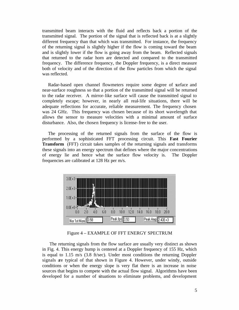
transmitted beam interacts with the fluid and reflects back a portion of the transmitted signal. The portion of the signal that is reflected back is at a slightly different frequency than that which was transmitted. For instance, the frequency of the returning signal is slightly higher if the flow is coming toward the beam and is slightly lower if the flow is going away from the beam. Reflected signals that returned to the radar horn are detected and compared to the transmitted frequency. The difference frequency, the Doppler frequency, is a direct measure both of velocity and of the direction of the flow particles from which the signal was reflected. Radar-based open channel flowmeters require some degree of surface and near-surface roughness so that a portion of the transmitted signal will be returned to the radar receiver. A mirror- like surface will cause the transmitted signal to completely escape; however, in nearly all real- life situations, there will be adequate reflections for accurate, reliable measurement. The frequency chosen was 24 GHz. This frequency was chosen because of its short wavelength that allows the sensor to measure velocities with a minimal amount of surface disturbance. Also, the chosen frequency is license-free to the user. The processing of the returned signals from the surface of the flow is performed by a sophisticated FFT processing circuit. This Fast Fourier Transform (FFT) circuit takes samples of the returning signals and transforms these signals into an energy spectrum that defines where the major concentrations of energy lie and hence what the surface flow velocity is. The Doppler frequencies are calibrated at 128 Hz per m/s.
Figure 4 – EXAMPLE OF FFT ENERGY SPECTRUM The returning signals from the flow surface are usually very distinct as shown in Fig. 4. This energy hump is centered at a Doppler frequency of 155 Hz, which is equal to 1.15 m/s (3.8 ft/sec). Under most conditions the returning Doppler signals are typical of that shown in Figure 4. However, under windy, outside conditions or when the energy slope is very flat there is an increase in noise sources that begins to compete with the actual flow signal. Algorithms have been developed for a number of situations to eliminate problems, and development

6
continues so as to extend the range of the radar flowmeter into a number of very difficult applications.
The accurate measurement of open channel flow requires the accurate measurement of the mean velocity of the flow stream. The radar open channel flowmeter, like other flowmeters, does not directly measure the mean velocity of the flow stream directly. Like other flowmeters, it must augment the sensed velocity with a relationship that converts the sensed velocity to the mean velocity. Since the position of the beam relative to the flow surface is known (it is generally in the center of the channel, but can be elsewhere) algorithms defining the relationship between the sensed velocity and the average velocity of the flow stream can be determined to an accuracy of ± 5% or better. Referring to Fig. 5 and 6, we see that the flow in an open channel situation consists of a contour of velocities that vary from near zero at the channel walls to a maximum just below the surface.
Figure 5 – VELOCITY PROFILE Figure 6 – VELOCITY PROFILE IN IN CIRCULAR PIPE RECTANGULAR PIPE
Note, also, that the various velocity profile lines generally terminate along the surface of the flow. In other words, a fingerprint of the flow profiles exists on the surface itself. By analyzing the surface and near-surface fingerprint of the flow channel, a relationship between where the radar-sensed velocity occurs and the average velocity of the flow stream can be determined to a reasonable accuracy. While currently available radar open channel flowmeters rely upon this relationship of sensed velocity to average velocity at the center of the pipe, it is expected that an algorithm will soon be available that will enable the radar flowmeter to provide accurate flow under distorted flow situations. Like all flowmetering devices, for best accuracy the flow needs to be reasonably uniform in nature. Making a flow measurement near bends and elbows or downstream from major disturbances can significantly distort the flow profile and result in a less accurate measurement. METHODOLOGY Open channel flows exist as part of many natural and man-made processes. Essentially, open channel flow is flow in which there is a free surface. The flow

7
channels are a common site to all of us – they include rivers, aqueducts, and sanitary and storm sewers. The range of flows in these systems varies from just a trickle to a raging torrent. The channel sizes of interest are as small as a 100 mm pipe to a river tens of meters wide. The testing criteria for this new radar flow sensor was designed to include both small and mid-size manmade channels over a variety of flow ranges covering a span virtually empty to nearly full capacity. Because the radar flow sensor requires a free surface, a simply designed radar unit will not be able to detect velocities under submerged conditions. Therefore no tests were preformed under surcharged or submerged conditions. HYDRAULIC FACILITIES Marsh-McBirney maintains a hydraulic research facility in its plant in Frederick, MD. This facility consists of a towing carriage that is 1.5 meters wide by 1.5 meters deep and is approximately 40 meters long. Marsh-McBirney also maintains a recirculating flow facility with a “volume tank” for calibration. Two magnetic flowmeters are used as secondary standards in the full-pipe section of the hydraulic facility. The facility has the ability to use various pipe sizes from 100 mm to 400 mm in diameter under open channel conditions where both the flow rate and the pipe slope can be independently controlled. To develop the necessary algorithms for converting surface velocity to average velocity, Marsh-McBirney used its internal flow facility and a number of field sites that had either 1) carefully calibrated flowmeters previously installed or 2) was calibrated by using velocity profiling of the site with a point velocity meter at different flow rates. RESULTS Laboratory Results Developmental tests were performed in 250 mm and 400 mm diameter circular pipes. Flow depths ranged from 5 mm to 70 % full. The test flowmeter exhibited a high degree of repeatability (+/- 3 %) over a variety of pipe slopes ranging from 0.25 % to 7 %. Application of a depth dependent corrector resulted in a typical accuracy of +/- 5 %. Field Experience Doppler Radar flowmeter have been used in the field in hundreds of applications; circular pipes as small as 15 mm in diameter and as large as 2 meters in diameter. Additionally, large rectangular channels up to 3 meters in width have

8
been instrumented as well as a variety of common pipe sizes used in wastewater collection systems. Some interesting applications are as follows: In –Line with a Flume At Washington Suburban Sanitary Commission (WSSC), Washington, DC, a new, small grit moving-screen filter system had been installed in- line with one of four flumes used for monitoring the plant influent into the treatment process. Unfortunately, the filters were so effective that they collected excessive debris such that the outflow from the chambers was slowed, causing the flumes to be submerged under heavy inflow.
Figure 7 – DOPPLER RADAR FLOWMETER IN-LINE WITH FLUME
A Doppler radar meter was installed upstream from the Parshall flume and its calibration checked at various flow rates with a point velocity meter and a hand held depth gauge. Fig 7 shows the reported data from both the radar meter and the Parshall flume inline with the radar meter. Note that for flows less than 12 MGD the flume and the radar meter track each other within ± 5%. However, as flow increased from the inflow from storm, the flow rates between the flume and the radar device deviated very significantly, with the flume flow being higher than thought reasonable. Shown also on this graph are the spot flow checks made by the handheld velocity meter and level device. Note that the flow check using the handheld velocity meter shows that the Flo-Dar was reporting within ± 5% of the handheld device, whereas the flume was over reporting flow by 30%.

9
Of additional interest is that during various tests at the site, it was observed that the velocity/level relationship varied significantly once the flume was submerged, but accuracies continued to be within the ± 5% range. Steep Terrain
In steep terrain the flow velocities can be very fast, approaching 3 m/s or faster. These velocities can occur with both shallow and deep water depths. Figure 8 shows a scatter graph of the velocity/level relationship of such a condition. Because there is no sensor in the flow, one does not have to worry about the drawdown effect typical of many pressure transducer based level devices and the flow remains undisturbed while the measurement is being made.
Figure 8 - SCATTER PLOT OF STEEP SLOPED SITE
In-Line with an EM meter Because the radar-based flowmeter is extremely portable and does not require the placement of bands or other apparatus in the flow stream, it lends itself to being easily transported from one site to another. Fig. 9 shows the results of a comparison study of a radar meter installed in 600 mm sewer along with an electromagnetic flowmeter.

10
Figure 9 - COMPARISON OF DOPPLER RADAR FLOWMETER WITH
ELECTROMAGNETIC FLOWMETER
COMPARISON OF ATTRIBUTES OF VARIOUS FLOWMETERS From 30 years of personal experience in designing and testing various flowmeters for the wastewater field and from information gleamed from many articles, the author has assembled comparison charts for the attributes of various flowmeters. Table 1 shows a comparison of attributes of the flume with various type area/velocity flowmeters. Note that the accuracy of the various submerged flowmeters varies as well as the flow range from the maximum flow that they can accurately measure to the minimum flow that they can actually measure. Of all the submersible type flowmeters, the transit time technique tends to be the most accurate. However, transit time instruments are typically used only in large channels since they require a minimum flow depth to operate. Ease of installation is an important aspect of flowmeters, especially those that are transported from one site to another. In small pipes of 600 mm or less in diameter, most of the submersible flowmeters can be installed with only moderate difficulty. However, in pipe sizes of greater than 600 mm most of the submerged sensors become very difficult to install, due to the danger and the forces involved in installing sensors at the bottom of a pipe carrying significant flow. The power requirement of the radar flowmeter is comparable to that used by other area/velocity flowmeters. For instance, for typical applications where data is collected once every 15 minutes, the radar portable flowmeter batteries can last as long as 12 weeks. Portable radar flowmeters are designed with dataloggers similar to other area/velocity meters where the user can use laptop computers to extract the data and proprietary software to obtain the necessary data in desirable formats.

11
Table 1 - COMPARISON OF FLUME WITH VARIOUS AREA/VELOCITY
FLOWMETERS
Installation Difficulty
Channel Width
Flowmeter Type Accuracy
Flow Range <600mm >600mm Maintenance
Submerged CW Doppler +/-10-20% 100:1
Easy to moderate
Difficult-Very Difficult Med-High
Pulse Doppler +/-2-5% 200:1 Moderate
Difficult-Very Difficult Med-High
Electro- magnetic +/-5% 100:1
Easy to moderate
Difficult-Very Difficult Med-High
Transit Time +/-2% 200:1
Moderate-Difficult Very Difficult Med
Non-Contact Flume +/-5% 20:1 Difficult Very Difficult Low
Doppler Radar +/-5% 500:1 Easy Easy Low
MAINTENANCE Low maintenance competes with accuracy as the most important feature of a wastewater flowmeter. The days of having the time to “tinker” with new-fangled flowmeters are over.
Table 2 discusses some of the maintenance issues associated with most flowmeters in use in wastewater systems today. The major causes of maintenance for submerged sensors are grease, silt, hang-ups on the sensor, and caustic or temperature deterioration of the submerged sensors. It is easy to see that most submerged sensors are affected to at least a medium extent by grease and silt and hang-ups causing erroneous readings and the need to visit the site to clean. Caustic substances and temperature affects tend to have harmful affects that ultimately result in the failure of the submerged sensor. Unlike the submerged sensors, the Doppler radar is much more like the flume. It is immune to grease, silt, hang-ups or the general make-up and temperature of the flowing fluid.

12
Table 2 - COMPARISON OF MAINTENANCE ISSUES OF VARIOUS FLOWMETERS
Fouling Environment
Flowmeter Type Grease Silt Hang-Up Caustics
Submerged CW Doppler P-F P P-F F-G
Pulse Doppler P-F P P-F F-G
Electromagnetic P-F P P-F F-G
Transit Time G-E Note: 1 G-E F-G
Non-Contact Flume E E E E
Doppler Radar E E E E
Comparison of Ease of Maintenance between Flowmeter Types P= Poor, F= Fair, G= Good, E= Excellent
Note 1- Sensor is located several inches above the channel bottom.
CONCLUSIONS Doppler Radar open channel flowmeters currently have been developed to such an extent that they provide a very attractive alternative to flumes. There are, however, two areas where Doppler Radar is not currently the right choice: 1) a flow where velocities go below approximately 15 cm/s (0.5 ft/sec) and the slope of the pipe is such that the water surface is very tranquil. Signal dropouts may occur and 2) submerged flow in which no reflections occur and data goes to zero. Developments are underway to provide the user with the means of obtaining velocity measurements during submergence. It is this author’s opinion that the Doppler Radar flowmeter has an accuracy equivalent to the flume; has a rangeability 50 times greater than the flume; is much easier to install than a flume, regardless of pipe size or channel size; and, unlike submerged Area/Velocity sensors, has the same low maintenance exhibited by the flume. Also, like a flume, it is unable to measure submerged flows without an additional sensor.