Embed Size (px)
Citation preview
INSTALLATIONINSTRUCTIONS
RDBS-1411 Instructions 02-02-17.docx Page 1 of 8 GS
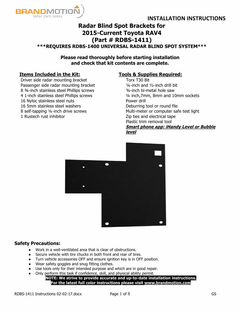
Radar Blind Spot Brackets for 2015-Current Toyota RAV4
(Part # RDBS-1411) ***REQUIRES RDBS-1400 UNIVERSAL RADAR BLIND SPOT SYSTEM***
Please read thoroughly before starting installation
and check that kit contents are complete.
Items Included in the Kit: Tools & Supplies Required: Driver side radar mounting bracket Passenger side radar mounting bracket 8 ¾-inch stainless steel Phillips screws 4 1-inch stainless steel Phillips screws 16 Nyloc stainless steel nuts 16 5mm stainless steel washers 8 self-tapping ¼-inch drive screws 1 Rustech rust inhibitor
Torx T30 Bit ¼-inch and ½-inch drill bit ¾-inch bi-metal hole saw ¼ inch,7mm, 8mm and 10mm sockets Power drill Deburring tool or round file Multi-meter or computer safe test light Zip ties and electrical tape Plastic trim removal tool Smart phone app: iHandy Level or Bubble level
Safety Precautions:
● Work in a well-ventilated area that is clear of obstructions. ● Secure vehicle with tire chucks in both front and rear of tires. ● Turn vehicle accessories OFF and ensure ignition key is in OFF position. ● Wear safety goggles and snug fitting clothes. ● Use tools only for their intended purpose and which are in good repair. ● Only perform this task if confidence, skill, and physical ability permit.
NOTE: We strive to provide accurate and up-to-date installation instructions. For the latest full color instructions please visit www.brandmotion.com
INSTALLATIONINSTRUCTIONS
RDBS-1411 Instructions 02-02-17.docx Page 2 of 8 GS
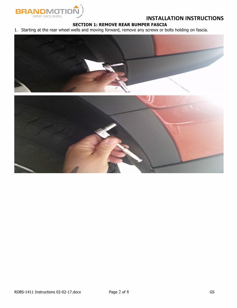
SECTION 1: REMOVE REAR BUMPER FASCIA 1. Starting at the rear wheel wells and moving forward, remove any screws or bolts holding on fascia.
INSTALLATIONINSTRUCTIONS
RDBS-1411 Instructions 02-02-17.docx Page 3 of 8 GS
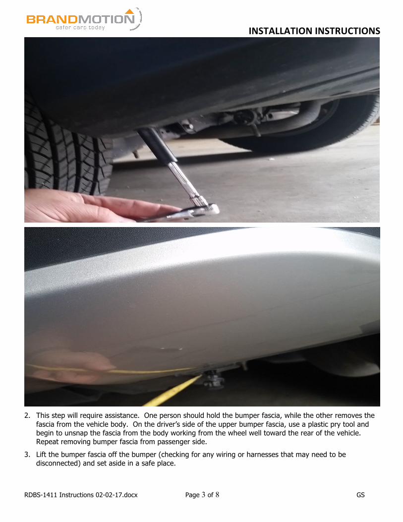
2. This step will require assistance. One person should hold the bumper fascia, while the other removes the
fascia from the vehicle body. On the driver’s side of the upper bumper fascia, use a plastic pry tool and begin to unsnap the fascia from the body working from the wheel well toward the rear of the vehicle. Repeat removing bumper fascia from passenger side.
3. Lift the bumper fascia off the bumper (checking for any wiring or harnesses that may need to be disconnected) and set aside in a safe place.
INSTALLATIONINSTRUCTIONS
RDBS-1411 Instructions 02-02-17.docx Page 4 of 8 GS
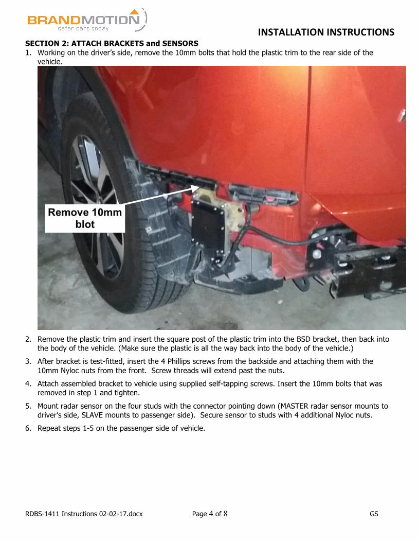
SECTION 2: ATTACH BRACKETS and SENSORS 1. Working on the driver’s side, remove the 10mm bolts that hold the plastic trim to the rear side of the
vehicle.
2. Remove the plastic trim and insert the square post of the plastic trim into the BSD bracket, then back into
the body of the vehicle. (Make sure the plastic is all the way back into the body of the vehicle.) 3. After bracket is test-fitted, insert the 4 Phillips screws from the backside and attaching them with the
10mm Nyloc nuts from the front. Screw threads will extend past the nuts. 4. Attach assembled bracket to vehicle using supplied self-tapping screws. Insert the 10mm bolts that was
removed in step 1 and tighten. 5. Mount radar sensor on the four studs with the connector pointing down (MASTER radar sensor mounts to
driver’s side, SLAVE mounts to passenger side). Secure sensor to studs with 4 additional Nyloc nuts. 6. Repeat steps 1-5 on the passenger side of vehicle.
INSTALLATIONINSTRUCTIONS
RDBS-1411 Instructions 02-02-17.docx Page 5 of 8 GS
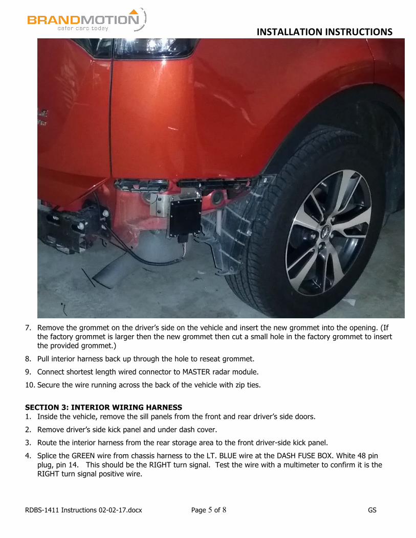
7. Remove the grommet on the driver’s side on the vehicle and insert the new grommet into the opening. (If
the factory grommet is larger then the new grommet then cut a small hole in the factory grommet to insert the provided grommet.)
8. Pull interior harness back up through the hole to reseat grommet. 9. Connect shortest length wired connector to MASTER radar module. 10. Secure the wire running across the back of the vehicle with zip ties. SECTION 3: INTERIOR WIRING HARNESS 1. Inside the vehicle, remove the sill panels from the front and rear driver’s side doors. 2. Remove driver’s side kick panel and under dash cover. 3. Route the interior harness from the rear storage area to the front driver-side kick panel. 4. Splice the GREEN wire from chassis harness to the LT. BLUE wire at the DASH FUSE BOX. White 48 pin
plug, pin 14. This should be the RIGHT turn signal. Test the wire with a multimeter to confirm it is the RIGHT turn signal positive wire.
INSTALLATIONINSTRUCTIONS
RDBS-1411 Instructions 02-02-17.docx Page 6 of 8 GS
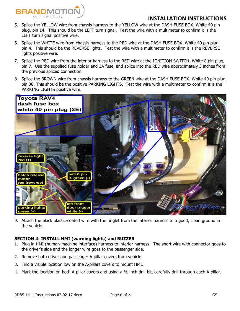
5. Splice the YELLOW wire from chassis harness to the YELLOW wire at the DASH FUSE BOX. White 40 pin plug, pin 14. This should be the LEFT turn signal. Test the wire with a multimeter to confirm it is the LEFT turn signal positive wire.
6. Splice the WHITE wire from chassis harness to the RED wire at the DASH FUSE BOX. White 40 pin plug, pin 4. This should be the REVERSE lights. Test the wire with a multimeter to confirm it is the REVERSE lights positive wire.
7. Splice the RED wire from the interior harness to the RED wire at the IGNITION SWITCH. White 8 pin plug, pin 7. Use the supplied fuse holder and 3A fuse, and splice into the RED wire approximately 3 inches from the previous spliced connection.
8. Splice the BROWN wire from chassis harness to the GREEN wire at the DASH FUSE BOX. White 40 pin plug pin 38. This should be the positive PARKING LIGHTS. Test the wire with a multimeter to confirm it is the PARKING LIGHTS positive wire.
9. Attach the black plastic-coated wire with the ringlet from the interior harness to a good, clean ground in
the vehicle. SECTION 4: INSTALL HMI (warning lights) and BUZZER 1. Plug in HMI (human-machine interface) harness to interior harness. The short wire with connector goes to
the driver’s side and the longer wire goes to the passenger side. 2. Remove both driver and passenger A-pillar covers from vehicle. 3. Find a visible location low on the A-pillars covers to mount HMI. 4. Mark the location on both A-pillar covers and using a ½-inch drill bit, carefully drill through each A-pillar.

INSTALLATIONINSTRUCTIONS
RDBS-1411 Instructions 02-02-17.docx Page 7 of 8 GS
5. Insert HMI into drilled hole and secure from the back side of A-pillar cover using retaining washer.
6. Plug in HMI to HMI harness and re-attach A-pillar covers to appropriate sides, taking care not to pinch HMI
harness wires. 7. Plug the buzzer into the interior harness. Find a flat surface to mount the buzzer to and remove backing of
INSTALLATIONINSTRUCTIONS
RDBS-1411 Instructions 02-02-17.docx Page 8 of 8 GS
double-sided tape to attach to preferred location. (The more hidden the location is, the lower the buzzer volume with be.)
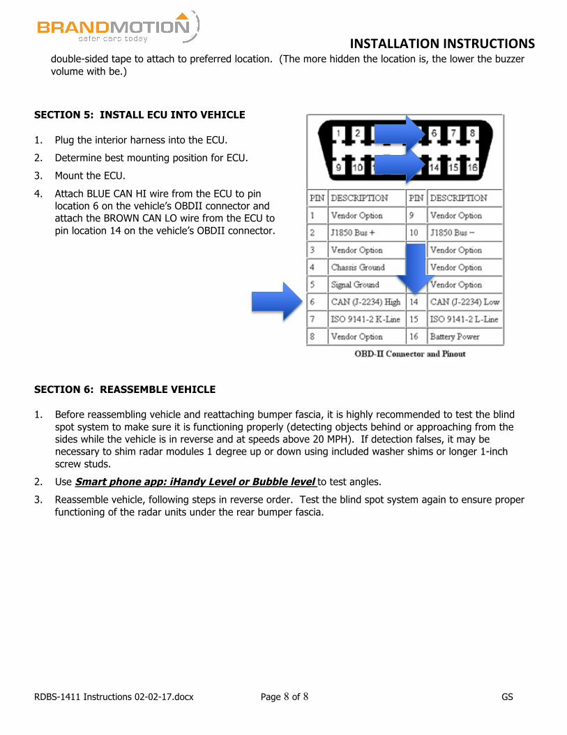
SECTION 5: INSTALL ECU INTO VEHICLE 1. Plug the interior harness into the ECU. 2. Determine best mounting position for ECU. 3. Mount the ECU. 4. Attach BLUE CAN HI wire from the ECU to pin
location 6 on the vehicle’s OBDII connector and attach the BROWN CAN LO wire from the ECU to pin location 14 on the vehicle’s OBDII connector.
SECTION 6: REASSEMBLE VEHICLE 1. Before reassembling vehicle and reattaching bumper fascia, it is highly recommended to test the blind
spot system to make sure it is functioning properly (detecting objects behind or approaching from the sides while the vehicle is in reverse and at speeds above 20 MPH). If detection falses, it may be necessary to shim radar modules 1 degree up or down using included washer shims or longer 1-inch screw studs.
2. Use Smart phone app: iHandy Level or Bubble level to test angles. 3. Reassemble vehicle, following steps in reverse order. Test the blind spot system again to ensure proper
functioning of the radar units under the rear bumper fascia.