Embed Size (px)
Citation preview
K. W. O’Haver et al.
Johns Hopkins APL Technical Digest, Volume 34, Number 2 (2018), www.jhuapl.edu/techdigest140
Radar Development for Air and Missile Defense
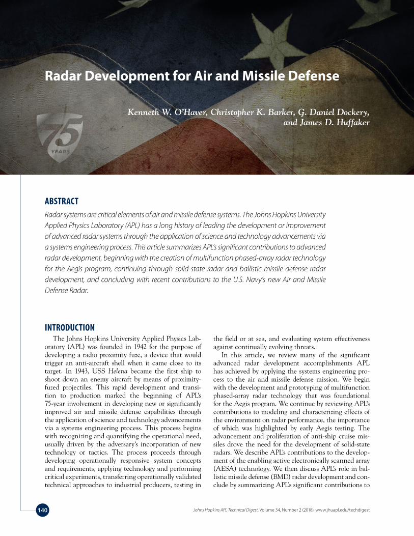
Kenneth W. O’Haver, Christopher K. Barker, G. Daniel Dockery, and James D. Huffaker
ABSTRACTRadar systems are critical elements of air and missile defense systems. The Johns Hopkins University Applied Physics Laboratory (APL) has a long history of leading the development or improvement of advanced radar systems through the application of science and technology advancements via a systems engineering process. This article summarizes APL’s significant contributions to advanced radar development, beginning with the creation of multifunction phased-array radar technology for the Aegis program, continuing through solid-state radar and ballistic missile defense radar development, and concluding with recent contributions to the U.S. Navy’s new Air and Missile Defense Radar.
the field or at sea, and evaluating system effectiveness against continually evolving threats.
In this article, we review many of the significant advanced radar development accomplishments APL has achieved by applying the systems engineering pro-cess to the air and missile defense mission. We begin with the development and prototyping of multifunction phased-array radar technology that was foundational for the Aegis program. We continue by reviewing APL’s contributions to modeling and characterizing effects of the environment on radar performance, the importance of which was highlighted by early Aegis testing. The advancement and proliferation of anti-ship cruise mis-siles drove the need for the development of solid-state radars. We describe APL’s contributions to the develop-ment of the enabling active electronically scanned array (AESA) technology. We then discuss APL’s role in bal-listic missile defense (BMD) radar development and con-clude by summarizing APL’s significant contributions to
INTRODUCTIONThe Johns Hopkins University Applied Physics Lab-
oratory (APL) was founded in 1942 for the purpose of developing a radio proximity fuze, a device that would trigger an anti-aircraft shell when it came close to its target. In 1943, USS Helena became the first ship to shoot down an enemy aircraft by means of proximity-fuzed projectiles. This rapid development and transi-tion to production marked the beginning of APL’s 75-year involvement in developing new or significantly improved air and missile defense capabilities through the application of science and technology advancements via a systems engineering process. This process begins with recognizing and quantifying the operational need, usually driven by the adversary’s incorporation of new technology or tactics. The process proceeds through developing operationally responsive system concepts and requirements, applying technology and performing critical experiments, transferring operationally validated technical approaches to industrial producers, testing in
Radar Development for Air and Missile Defense
Johns Hopkins APL Technical Digest, Volume 34, Number 2 (2018), www.jhuapl.edu/techdigest 141
the recent development of the Navy’s new Air and Mis-sile Defense Radar (AMDR).
AEGIS MULTIFUNCTION PHASED-ARRAY RADARAs the capabilities of air threats continued to evolve
in the 1950s, it became apparent that naval weapons sys-tems would require radars that could reposition beams within microseconds to track increasing numbers of tar-gets. APL initially attempted to address this need with an early experimental system concept named Typhon.1 The Typhon antenna electronically switched beams by means of a Luneburg lens. Energy entering the lens at a particular point will exit as a plane wave, and energy entering at another point will exit as a plane wave in a different direction. This principle was used to devise a radar that switched energy to various lens input ports using microwave switches, with the resulting beams being switched to various angular locations within microseconds. Numerous technical problems were solved in developing the Typhon system and installing it on the test ship USS Norton Sound, and successful search and track tests were performed. However, the system could not be produced at an acceptable cost, and the program was terminated in 1963.
In the latter stages of the Typhon program, research-ers at APL and elsewhere began developing electronic phase-shifter technology, which enabled a high-gain phased-array antenna in which the radar beam could be steered or pointed electronically through the control of phase across the radiating elements of an aperture.2 A 1965 Navy study identified the requirement for a phased-array radar with combined surveillance, track-ing, and missile-guidance capabilities along with high resistance to electronic countermeasures. Given APL’s background in phased-array technology and naval air defense, the Navy directed APL to begin a program to reduce technological risk and demonstrate the requi-site phased-array radar performance. This experimental development program was named the Advanced Multi-Function Array Radar (AMFAR).
AMFAR to AN/SPY-1The AMFAR demonstrator was conceived, designed,
fabricated, and tested by APL between 1964 and 1969 and served as the advanced development model for tech-nologies incorporated into the Aegis AN/SPY-1A radar. It brought all elements of the radar system together and demonstrated the feasibility of automatic detection and tracking with resistance to environmental clut-ter through computer control. Key technology areas addressed by the AMFAR program included tube-based transmitter design, planar phased-array design, elec-tronic counter-countermeasures (now known as elec-tronic protection) development, automatic detection
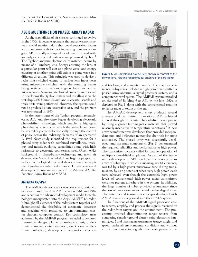
and tracking, and computer control. The major experi-mental subsystems included a high-power transmitter, a phased-array antenna, a signal-processor system, and a computer control system. The AMFAR system, installed on the roof of Building 6 at APL in the late 1960s, is depicted in Fig. 1 along with the conventional rotating reflector radar antenna of the era.
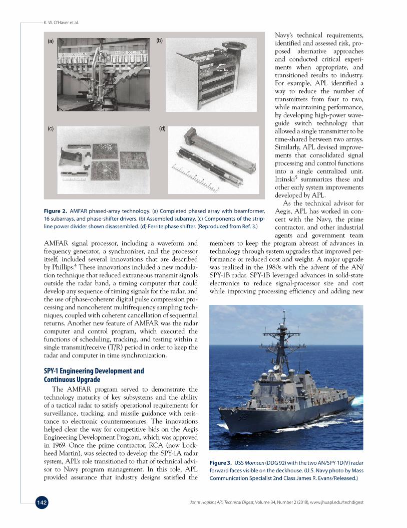
The AMFAR development effort produced several antenna and transmitter innovations. APL achieved a breakthrough in ferrite phase-shifter development by using a garnet ferromagnetic material that proved relatively insensitive to temperature variations.2 A new array beamformer was developed that provided indepen-dent sum and difference monopulse channels for angle estimation. The phased array was successfully devel-oped, and the array components (Fig. 2) demonstrated the required reliability and performance at high power. The transmitter concept called for parallel operation of multiple crossed-field amplifiers. As part of the trans-mitter development, APL developed the concept of an array of subarrays in which a subarray, say 64 elements, was fed by a high-power microwave tube during trans-mission. By using dozens of tubes, very high power levels were achieved even though the extremely high power levels of conventional high-power radar transmitters were not present anywhere in the system. In addition, the large number of tubes provided redundancy since the loss of one or two tubes caused modest degradation. The antenna and transmitter concepts developed with AMFAR were incorporated into the SPY-1A system.
The functions of the AMFAR signal processor were to receive, amplify, and process the signals received by the radar from targets and the environment. The pro-cessing involved discriminating target returns from competing signals (ground clutter, rain, electronic jam-ming, etc.) and making measurements (range, angle, and speed) under all environmental conditions and without errors from competing signals. The development of the
Figure 1. APL-developed AMFAR (left) shown in contrast to the conventional rotating reflector radar antenna of the era (right).
K. W. O’Haver et al.
Johns Hopkins APL Technical Digest, Volume 34, Number 2 (2018), www.jhuapl.edu/techdigest142
AMFAR signal processor, including a waveform and frequency generator, a synchronizer, and the processor itself, included several innovations that are described by Phillips.4 These innovations included a new modula-tion technique that reduced extraneous transmit signals outside the radar band, a timing computer that could develop any sequence of timing signals for the radar, and the use of phase-coherent digital pulse compression pro-cessing and noncoherent multifrequency sampling tech-niques, coupled with coherent cancellation of sequential returns. Another new feature of AMFAR was the radar computer and control program, which executed the functions of scheduling, tracking, and testing within a single transmit/receive (T/R) period in order to keep the radar and computer in time synchronization.
SPY-1 Engineering Development and Continuous Upgrade
The AMFAR program served to demonstrate the technology maturity of key subsystems and the ability of a tactical radar to satisfy operational requirements for surveillance, tracking, and missile guidance with resis-tance to electronic countermeasures. The innovations helped clear the way for competitive bids on the Aegis Engineering Development Program, which was approved in 1969. Once the prime contractor, RCA (now Lock-heed Martin), was selected to develop the SPY-1A radar system, APL’s role transitioned to that of technical advi-sor to Navy program management. In this role, APL provided assurance that industry designs satisfied the
Navy’s technical requirements, identified and assessed risk, pro-posed alternative approaches and conducted critical experi-ments when appropriate, and transitioned results to industry. For example, APL identified a way to reduce the number of transmitters from four to two, while maintaining performance, by developing high-power wave-guide switch technology that allowed a single transmitter to be time-shared between two arrays. Similarly, APL devised improve-ments that consolidated signal processing and control functions into a single centralized unit. Irzinski5 summarizes these and other early system improvements developed by APL.
As the technical advisor for Aegis, APL has worked in con-cert with the Navy, the prime contractor, and other industrial agents and government team
members to keep the program abreast of advances in technology through system upgrades that improved per-formance or reduced cost and weight. A major upgrade was realized in the 1980s with the advent of the AN/SPY-1B radar. SPY-1B leveraged advances in solid-state electronics to reduce signal-processor size and cost while improving processing efficiency and adding new
(a) (b)
(c) (d)
Figure 2. AMFAR phased-array technology. (a) Completed phased array with beamformer, 16 subarrays, and phase-shifter drivers. (b) Assembled subarray. (c) Components of the strip-line power divider shown disassembled. (d) Ferrite phase shifter. (Reproduced from Ref. 3.)
Figure 3. USS Momsen (DDG 92) with the two AN/SPY-1D(V) radar forward faces visible on the deckhouse. (U.S. Navy photo by Mass Communication Specialist 2nd Class James R. Evans/Released.)
Radar Development for Air and Missile Defense
Johns Hopkins APL Technical Digest, Volume 34, Number 2 (2018), www.jhuapl.edu/techdigest 143
electronic protection capabilities. Similarly, changes in the array architecture and advances in manufacturing tolerances and array calibration techniques allowed the SPY-1B phased array to achieve low sidelobe perfor-mance and improved electronic protection.
The SPY-1 radar (Fig. 3) that emerged from APL’s original concept development studies and the experi-mental development of AMFAR, and has evolved through numerous improvements and upgrades, has served as the centerpiece for the Navy’s Aegis Combat System for nearly four decades. Over 90 ships have been outfitted with a version of the SPY-1 radar.
PERFORMANCE ASSESSMENT AND ENVIRONMENTAL CHARACTERIZATION
One of the drivers for the development of SPY-1 was the need to address the low-altitude anti-ship cruise missile threat, which stresses the engagement time-line of the combat system because threats emerge from behind the Earth’s horizon at relatively short ranges from the ship. To characterize the performance of the new radar system, two things were needed: (i) a high-fidelity simulation of the radar, including the schedul-ing of rapid confirmation dwells and the ability to do Monte Carlo statistical analysis, and (ii) the capabil-ity to predict the impact of low-altitude propagation and surface clutter on system performance. In the late 1970s, APL developed the first incarnation of the Firm-Track Simulation, which provided the ability to analyze behaviors specific to electronically steered phased-array radars. The term firm track was established at this time to capture the track initiation process that is enabled by this class of radar.
The APL FirmTrack Simulation has evolved along-side the SPY-1 radar system and its expanding missions (open-ocean air defense, air defense in littoral regions,
ballistic missile defense, and integrated air and mis-sile defense). As ship-based testing of the first genera-tion of SPY-1 radars began, the FirmTrack Simulation was used to compare radar performance predictions to the actual performance observed in the testing. At that time, the simulation included models to account for low-elevation multipath and spherical Earth horizon effects with nominal atmosphere refraction. Despite this fidel-ity, the observed firm track performance of the radar rarely agreed with the simulation predictions for low-altitude test targets, and the observed performance was extremely variable. It was clear that performance pre-dictions must include atmospheric refraction effects on low-elevation RF propagation to enable understanding of radar performance in this regime.
Modeling of Environmental Effects on Radar Performance
By the early 1980s, APL had developed the Electro-magnetic Parabolic Equation (EMPE) model to describe electromagnetic propagation in the lower atmosphere.6 The Aegis program began supporting this work in 1982, and by 1985, the EMPE was being used in con-cert with the FirmTrack Simulation to account for low-altitude propagation effects in SPY-1 performance predictions. After experimental validation and many fidelity improvements, the model was renamed the Tro-pospheric Electromagnetic Parabolic Equation Routine (TEMPER). Today, TEMPER is capable of predicting electromagnetic propagation over land and sea and accurately represents radar and communication system antenna patterns.7 TEMPER has been accredited mul-tiple times in support of many Navy and Missile Defense Agency (MDA) programs and is widely used by Navy laboratories and industry partners.
TEMPER calculations confirmed that radar behav-ior is very sensitive to the atmospheric refraction con-
4 m evaporation duct 14 m evaporation duct 24 m evaporation duct
20 40 60 80 100
Alt
itud
e (m
)
50
40
30
20
10
02000 040 60 80 100
Alt
itud
e (m
)
50
40
30
20
10
020 40 60 80 100
Alt
itud
e (m
)
50
40
30
20
10
0
Range (km)
F2 in decibels
Range (km)Range (km)
100–10–20–30–40–50
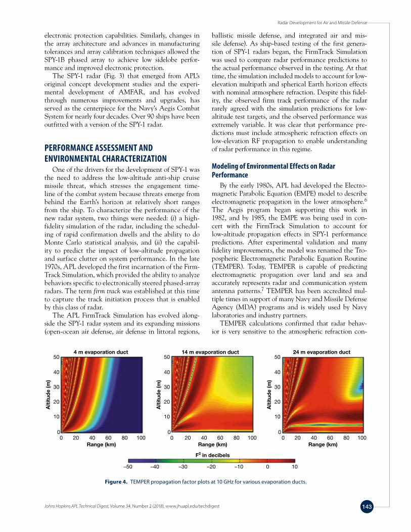
Figure 4. TEMPER propagation factor plots at 10 GHz for various evaporation ducts.
K. W. O’Haver et al.
Johns Hopkins APL Technical Digest, Volume 34, Number 2 (2018), www.jhuapl.edu/techdigest144
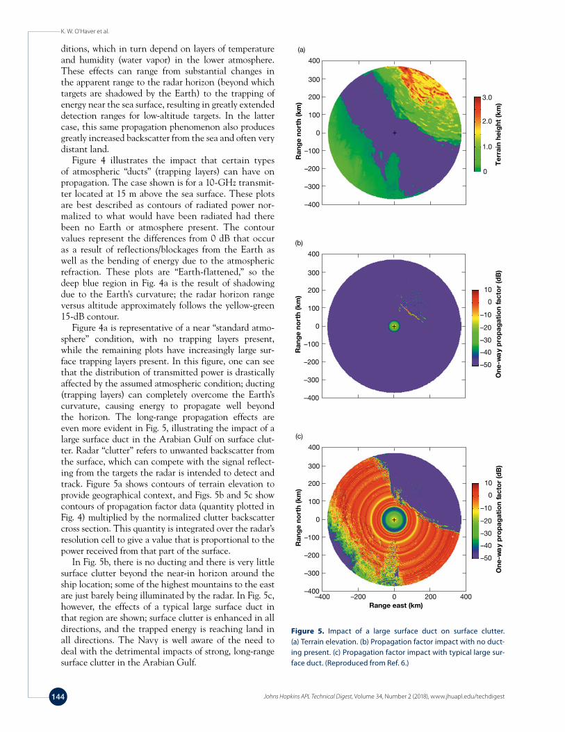
ditions, which in turn depend on layers of temperature and humidity (water vapor) in the lower atmosphere. These effects can range from substantial changes in the apparent range to the radar horizon (beyond which targets are shadowed by the Earth) to the trapping of energy near the sea surface, resulting in greatly extended detection ranges for low-altitude targets. In the latter case, this same propagation phenomenon also produces greatly increased backscatter from the sea and often very distant land.
Figure 4 illustrates the impact that certain types of atmospheric “ducts” (trapping layers) can have on propagation. The case shown is for a 10-GHz transmit-ter located at 15 m above the sea surface. These plots are best described as contours of radiated power nor-malized to what would have been radiated had there been no Earth or atmosphere present. The contour values represent the differences from 0 dB that occur as a result of reflections/blockages from the Earth as well as the bending of energy due to the atmospheric refraction. These plots are “Earth-flattened,” so the deep blue region in Fig. 4a is the result of shadowing due to the Earth’s curvature; the radar horizon range versus altitude approximately follows the yellow-green 15-dB contour.
Figure 4a is representative of a near “standard atmo-sphere” condition, with no trapping layers present, while the remaining plots have increasingly large sur-face trapping layers present. In this figure, one can see that the distribution of transmitted power is drastically affected by the assumed atmospheric condition; ducting (trapping layers) can completely overcome the Earth’s curvature, causing energy to propagate well beyond the horizon. The long-range propagation effects are even more evident in Fig. 5, illustrating the impact of a large surface duct in the Arabian Gulf on surface clut-ter. Radar “clutter” refers to unwanted backscatter from the surface, which can compete with the signal reflect-ing from the targets the radar is intended to detect and track. Figure 5a shows contours of terrain elevation to provide geographical context, and Figs. 5b and 5c show contours of propagation factor data (quantity plotted in Fig. 4) multiplied by the normalized clutter backscatter cross section. This quantity is integrated over the radar’s resolution cell to give a value that is proportional to the power received from that part of the surface.
In Fig. 5b, there is no ducting and there is very little surface clutter beyond the near-in horizon around the ship location; some of the highest mountains to the east are just barely being illuminated by the radar. In Fig. 5c, however, the effects of a typical large surface duct in that region are shown; surface clutter is enhanced in all directions, and the trapped energy is reaching land in all directions. The Navy is well aware of the need to deal with the detrimental impacts of strong, long-range surface clutter in the Arabian Gulf.
400
300
200
100
0
–100
–200
–300
–400
Ran
ge
nort
h (k
m)
10
0
–10
–20
–30
–40
–50
One
-wa
y p
rop
agat
ion
fact
or
(dB
)
(b)
400
300
200
100
0
–100
–200
–300
–400–400 –200 0 200 400
Ran
ge
nort
h (k
m)
Range east (km)
10
0
–10
–20
–30
–40
–50
(c)
One
-wa
y p
rop
agat
ion
fact
or
(dB
)
400
300
200
100
0
–100
–200
–300
–400
Ran
ge
nort
h (k
m)
3.0
2.0
1.0
0
Ter
rain
hei
ght
(km
)
(a)
Figure 5. Impact of a large surface duct on surface clutter. (a) Terrain elevation. (b) Propagation factor impact with no duct-ing present. (c) Propagation factor impact with typical large sur-face duct. (Reproduced from Ref. 6.)
Radar Development for Air and Missile Defense
Johns Hopkins APL Technical Digest, Volume 34, Number 2 (2018), www.jhuapl.edu/techdigest 145
Characterization of Atmospheric Refractive ConditionsGiven a model like TEMPER, and clutter models that
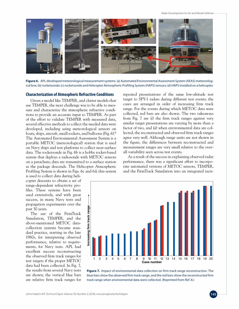
use TEMPER, the next challenge was to be able to mea-sure and characterize the atmospheric refractive condi-tions to provide an accurate input to TEMPER. As part of the effort to validate TEMPER with measured data, several effective methods to collect the needed data were developed, including using meteorological sensors on boats, ships, aircraft, small rockets, and balloons (Fig. 6).6 The Automated Environmental Assessment System is a portable METOC (meteorological) station that is used on Navy ships and test platforms to collect near-surface data. The rocketsonde in Fig. 6b is a hobby rocket-based system that deploys a radiosonde with METOC sensors on a parachute; data are transmitted to a surface station as the package descends. The Helicopter Atmospheric Profiling System is shown in Figs. 6c and 6d; this system is used to collect data during heli-copter descents to obtain a set of range-dependent refractivity pro-files. These systems have been used extensively, and with great success, in many Navy tests and propagation experiments over the past 30 years.
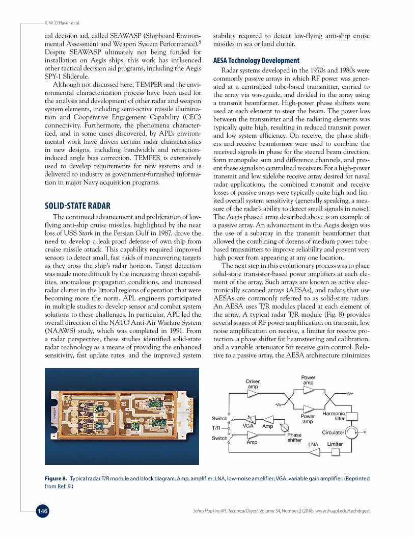
The use of the FirmTrack Simulation, TEMPER, and the above-mentioned METOC data-collection systems became stan-dard practice, starting in the late 1980s, for interpreting observed performance, relative to require-ments, for Navy tests. APL had excellent success reconstructing the observed firm track ranges for test targets if the proper METOC data had been collected. In Fig. 7, the results from several Navy tests are shown; the vertical blue bars are relative firm track ranges for
repeated presentations of the same low-altitude test target to SPY-1 radars during different test events; the cases are arranged in order of increasing firm track range. For the events during which METOC data were collected, red bars are also shown. The two takeaways from Fig. 7 are (i) the firm track ranges against very similar target presentations are varying by more than a factor of two, and (ii) when environmental data are col-lected, the reconstructed and observed firm track ranges agree very well. Although range units are not shown in the figure, the differences between reconstructed and measurement ranges are very small relative to the over-all variability seen across test events.
As a result of the success in explaining observed radar performance, there was a significant effort to incorpo-rate automated versions of METOC sensors, TEMPER, and the FirmTrack Simulation into an integrated tacti-
(a) (b) (c) (d)
Figure 6. APL-developed meteorological measurement systems. (a) Automated Environmental Assessment System (AEAS) meteorolog-ical box; (b) rocketsonde; (c) rocketsonde and Helicopter Atmospheric Profiling System (HAPS) sensors; (d) HAPS installed on a helicopter.
1 2 3 4 5 6 7 8 9 10 11 12 13 14 15 16 17 18 19 20Case number
Incr
easi
ng �
rm t
rack
ran
ge
Figure 7. Impact of environmental data collection on firm track range reconstruction. The blue bars show the observed firm track range, and the red bars show the reconstructed firm track range when environmental data were collected. (Reprinted from Ref. 8.)
K. W. O’Haver et al.
Johns Hopkins APL Technical Digest, Volume 34, Number 2 (2018), www.jhuapl.edu/techdigest146
cal decision aid, called SEAWASP (Shipboard Environ-mental Assessment and Weapon System Performance).8 Despite SEAWASP ultimately not being funded for installation on Aegis ships, this work has influenced other tactical decision aid programs, including the Aegis SPY-1 Sliderule.
Although not discussed here, TEMPER and the envi-ronmental characterization process have been used for the analysis and development of other radar and weapon system elements, including semi-active missile illumina-tion and Cooperative Engagement Capability (CEC) connectivity. Furthermore, the phenomena character-ized, and in some cases discovered, by APL’s environ-mental work have driven certain radar characteristics in new designs, including bandwidth and refraction-induced angle bias correction. TEMPER is extensively used to develop requirements for new systems and is delivered to industry as government-furnished informa-tion in major Navy acquisition programs.
SOLID-STATE RADARThe continued advancement and proliferation of low-
flying anti-ship cruise missiles, highlighted by the near loss of USS Stark in the Persian Gulf in 1987, drove the need to develop a leak-proof defense of own-ship from cruise missile attack. This capability required improved sensors to detect small, fast raids of maneuvering targets as they cross the ship’s radar horizon. Target detection was made more difficult by the increasing threat capabil-ities, anomalous propagation conditions, and increased radar clutter in the littoral regions of operation that were becoming more the norm. APL engineers participated in multiple studies to develop sensor and combat system solutions to these challenges. In particular, APL led the overall direction of the NATO Anti-Air Warfare System (NAAWS) study, which was completed in 1991. From a radar perspective, these studies identified solid-state radar technology as a means of providing the enhanced sensitivity, fast update rates, and the improved system
stability required to detect low-flying anti-ship cruise missiles in sea or land clutter.
AESA Technology DevelopmentRadar systems developed in the 1970s and 1980s were
commonly passive arrays in which RF power was gener-ated at a centralized tube-based transmitter, carried to the array via waveguide, and divided in the array using a transmit beamformer. High-power phase shifters were used at each element to steer the beam. The power loss between the transmitter and the radiating elements was typically quite high, resulting in reduced transmit power and low system efficiency. On receive, the phase shift-ers and receive beamformer were used to combine the received signals in phase for the steered beam direction, form monopulse sum and difference channels, and pres-ent these signals to centralized receivers. For a high-power transmit and low sidelobe receive array desired for naval radar applications, the combined transmit and receive losses of passive arrays were typically quite high and lim-ited overall system sensitivity (generally speaking, a mea-sure of the radar’s ability to detect small signals in noise). The Aegis phased array described above is an example of a passive array. An advancement in the Aegis design was the use of a subarray in the transmit beamformer that allowed the combining of dozens of medium-power tube-based transmitters to improve reliability and prevent very high power from appearing at any one location.
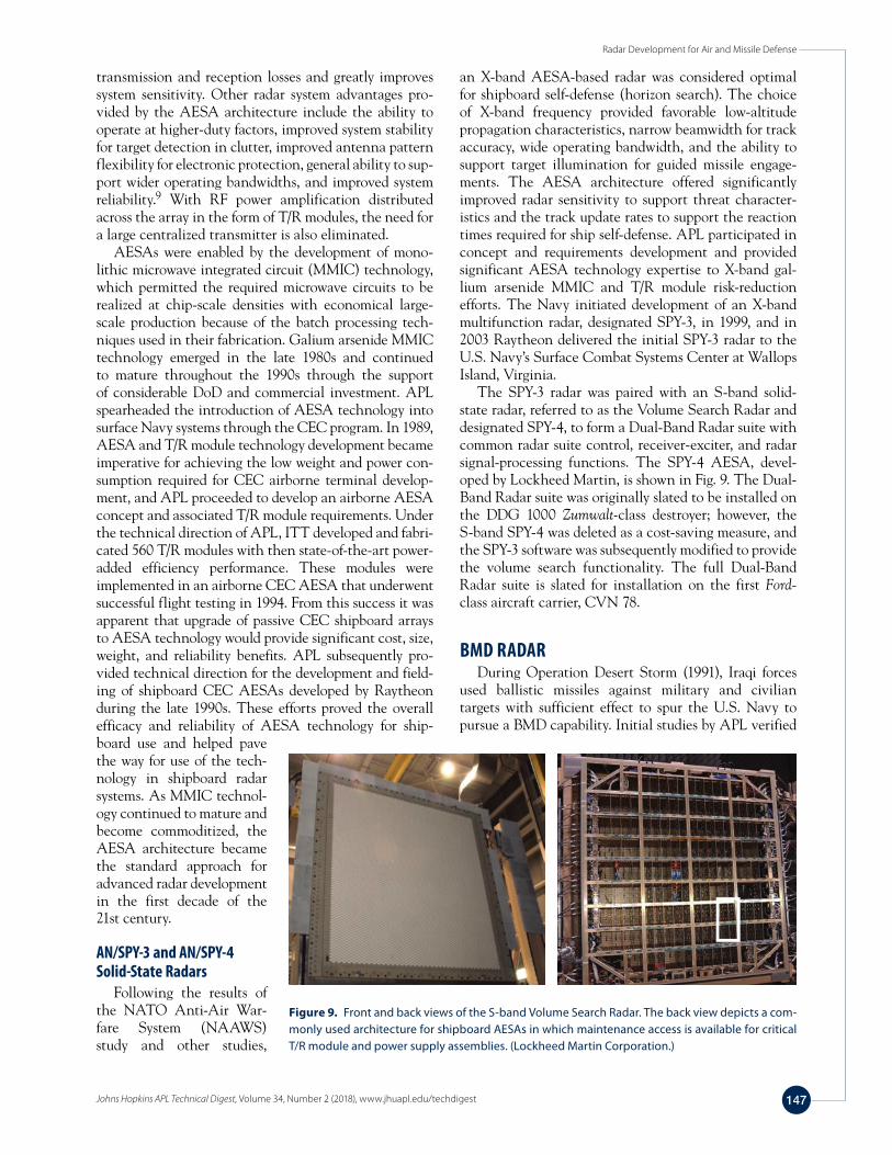
The next step in this evolutionary process was to place solid-state transistor-based power amplifiers at each ele-ment of the array. Such arrays are known as active elec-tronically scanned arrays (AESAs), and radars that use AESAs are commonly referred to as solid-state radars. An AESA uses T/R modules placed at each element of the array. A typical radar T/R module (Fig. 8) provides several stages of RF power amplification on transmit, low noise amplification on receive, a limiter for receive pro-tection, a phase shifter for beamsteering and calibration, and a variable attenuator for receive gain control. Rela-tive to a passive array, the AESA architecture minimizes
Poweramp
Poweramp
Harmonic�lter
CirculatorPhaseshifter
VGA Amp
Amp
Driveramp
Switch
Switch
T/R
LNA Limiter
Figure 8. Typical radar T/R module and block diagram. Amp, amplifier; LNA, low-noise amplifier; VGA, variable gain amplifier. (Reprinted from Ref. 9.)
Radar Development for Air and Missile Defense
Johns Hopkins APL Technical Digest, Volume 34, Number 2 (2018), www.jhuapl.edu/techdigest 147
transmission and reception losses and greatly improves system sensitivity. Other radar system advantages pro-vided by the AESA architecture include the ability to operate at higher-duty factors, improved system stability for target detection in clutter, improved antenna pattern flexibility for electronic protection, general ability to sup-port wider operating bandwidths, and improved system reliability.9 With RF power amplification distributed across the array in the form of T/R modules, the need for a large centralized transmitter is also eliminated.
AESAs were enabled by the development of mono-lithic microwave integrated circuit (MMIC) technology, which permitted the required microwave circuits to be realized at chip-scale densities with economical large-scale production because of the batch processing tech-niques used in their fabrication. Galium arsenide MMIC technology emerged in the late 1980s and continued to mature throughout the 1990s through the support of considerable DoD and commercial investment. APL spearheaded the introduction of AESA technology into surface Navy systems through the CEC program. In 1989, AESA and T/R module technology development became imperative for achieving the low weight and power con-sumption required for CEC airborne terminal develop-ment, and APL proceeded to develop an airborne AESA concept and associated T/R module requirements. Under the technical direction of APL, ITT developed and fabri-cated 560 T/R modules with then state-of-the-art power-added efficiency performance. These modules were implemented in an airborne CEC AESA that underwent successful flight testing in 1994. From this success it was apparent that upgrade of passive CEC shipboard arrays to AESA technology would provide significant cost, size, weight, and reliability benefits. APL subsequently pro-vided technical direction for the development and field-ing of shipboard CEC AESAs developed by Raytheon during the late 1990s. These efforts proved the overall efficacy and reliability of AESA technology for ship-board use and helped pave the way for use of the tech-nology in shipboard radar systems. As MMIC technol-ogy continued to mature and become commoditized, the AESA architecture became the standard approach for advanced radar development in the first decade of the 21st century.
AN/SPY-3 and AN/SPY-4 Solid-State Radars
Following the results of the NATO Anti-Air War-fare System (NAAWS) study and other studies,
an X-band AESA-based radar was considered optimal for shipboard self-defense (horizon search). The choice of X-band frequency provided favorable low-altitude propagation characteristics, narrow beamwidth for track accuracy, wide operating bandwidth, and the ability to support target illumination for guided missile engage-ments. The AESA architecture offered significantly improved radar sensitivity to support threat character-istics and the track update rates to support the reaction times required for ship self-defense. APL participated in concept and requirements development and provided significant AESA technology expertise to X-band gal-lium arsenide MMIC and T/R module risk-reduction efforts. The Navy initiated development of an X-band multifunction radar, designated SPY-3, in 1999, and in 2003 Raytheon delivered the initial SPY-3 radar to the U.S. Navy’s Surface Combat Systems Center at Wallops Island, Virginia.
The SPY-3 radar was paired with an S-band solid-state radar, referred to as the Volume Search Radar and designated SPY-4, to form a Dual-Band Radar suite with common radar suite control, receiver-exciter, and radar signal-processing functions. The SPY-4 AESA, devel-oped by Lockheed Martin, is shown in Fig. 9. The Dual-Band Radar suite was originally slated to be installed on the DDG 1000 Zumwalt-class destroyer; however, the S-band SPY-4 was deleted as a cost-saving measure, and the SPY-3 software was subsequently modified to provide the volume search functionality. The full Dual-Band Radar suite is slated for installation on the first Ford-class aircraft carrier, CVN 78.
BMD RADARDuring Operation Desert Storm (1991), Iraqi forces
used ballistic missiles against military and civilian targets with sufficient effect to spur the U.S. Navy to pursue a BMD capability. Initial studies by APL verified
Figure 9. Front and back views of the S-band Volume Search Radar. The back view depicts a com-monly used architecture for shipboard AESAs in which maintenance access is available for critical T/R module and power supply assemblies. (Lockheed Martin Corporation.)
K. W. O’Haver et al.
Johns Hopkins APL Technical Digest, Volume 34, Number 2 (2018), www.jhuapl.edu/techdigest148
the feasibility of modifying the Aegis Combat System, including the AN/SPY-1 radar and Standard Missile-2 Block IV, to add an Area BMD endo-atmospheric engagement capability to protect ports and forces ashore against ballistic missile threats such as the Scud variety seen in Desert Storm.
Key AN/SPY-1 advances necessary to support the new Area BMD mission included the ability to respond to cues from offboard sensors, increased sensitivity, new surveillance approaches for early detection of threats, new tracking approaches, and new functionality to dis-criminate ballistic missile warheads. APL worked closely in the early to mid-1990s with the Aegis prime contrac-tor, Lockheed Martin, and the Naval Surface Warfare Center Dahlgren Division to incrementally design and field-test each of these capabilities. APL continued to work closely with the team through the late 1990s to implement these new capabilities on top of exist-ing Aegis missions in the operational Aegis Baseline 6 phase III system. APL also worked closely with Lock-heed Martin to integrate CEC into the Aegis Baseline 6 phase III Area BMD mission including designs for dis-tributed weapon coordination and distributed sensor coordination—a means to share ballistic missile tracking responsibilities among multiple Area BMD ships. APL continued to support Baseline 6 phase III development, performance analysis, and demonstration test planning into early 2000 when the program was canceled.
Roughly in parallel with the development of the Area BMD program, the U.S. Navy initiated early develop-ment of exo-atmospheric intercept capabilities with suc-cessful Lightweight Exo-Atmospheric Projectile (LEAP) demonstrations, first using the Terrier combat system (Terrier-LEAP) and later with Aegis (Aegis Leap Inter-cept). In addition to the new interceptor that became Standard Missile-3 (SM-3), the new Navy Theater Wide program also included substantial Aegis radar, combat system, and weapon system development. Modifications to AN/SPY-1 included the implementation of a new waveform to enable discrimination capabilities, new surveillance approaches, and new tracking algorithms. APL provided significant support in the early design and analysis of candidate search, association, tracking, and discrimination algorithms. APL also served as a critical partner with Lockheed Martin and Raytheon in the cer-tification of the initial Theater BMD capability through the Linebacker program in the early 2000s and has con-tinued in this role through today’s Aegis BMD baselines.
With area and theater-wide BMD development efforts ongoing, the U.S. Navy became interested in the types of roles they might play in National Missile Defense (NMD). In late 1999, a large Navy NMD study team was assembled including APL, Navy laboratories and warfare centers, and several key federally funded research and development centers across the country. For this effort, APL led the Concept Formulation Work-
ing Group, which was charged with identifying and exploring well-outside-of-the-box approaches to NMD, including heavily modified and/or new missile systems, launchers, sensors, and ships to provide varying degrees of NMD capability, as well as concepts for globally dis-tributing and coordinating sensor and interceptor capa-bilities. Many of the basic ideas explored in this early Navy NMD study (e.g., forward-based sensors near the adversary supporting midcourse interceptors launched within or near U.S. territory) align well with the current-day MDA’s Ballistic Missile Defense System (BMDS).
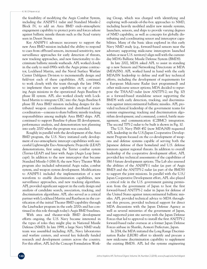
In late 2002, MDA asked APL to assist in standing up a new Sensors and Networking Directorate at MDA (MDA/SN). APL worked hand in hand with the early MDA/SN leadership to define and staff key technical efforts, including the development of requirements for a European Midcourse Radar (not programmed) and other midcourse sensor options; MDA decided to repur-pose the THAAD radar (now AN/TPY-2; see Fig. 10) as a forward-based standalone sensor supporting the BMDS with early detection, tracking, and discrimina-tion against intercontinental ballistic missiles. APL pro-vided technical leadership of the government teams for systems engineering; tracking and discrimination algo-rithm development; and command, control, battle man-agement, and communication (C2BMC) integration. The second TPY-2 radar to be built is shown in Fig. 10.
The U.S. Navy PMS 452 (now MDA/AB) requested APL leadership in the U.S./Japan Cooperative Develop-ment Program focused on the co-development of weap-ons and defense systems capable of serving both the Japanese defense of their homeland and U.S. defense interests against regional threats. In addition to overall leadership of the cooperative development effort, APL provided key technical assessments of the capabilities of SM-3 future development options. The Lab also assessed the abilities of the AN/SPY-1 radar (as part of Aegis BMD) and the AN/TPY-2 radar (as part of the BMDS)to support the joint missions. In parallel with the U.S./Japan Cooperative Development effort, APL also played a critical role in the U.S. government gaining permis-sion from the government of Japan to host the first forward-based AN/TPY-2 radar in Japan for defense of the United States against intercontinental ballistic mis-siles. APL provided technical advice to MDA through-out this process, provided technical support for direct MDA discussions with the Japan Defense Agency as well as several ministries of the government of Japan, and supported joint site surveys with the Japan Defense Forces that led to approval to install the first AN/TPY-2 forward-based radar overseas at a former Japan Defense Forces airbase in Shariki, Aomori Prefecture, Japan.
In 2014, the MDA initiated the Long Range Discrimi-nation Radar (LRDR) effort to identify and procure a new midcourse discrimination capability to supplement the existing BMDS. APL led the systems engineering
Radar Development for Air and Missile Defense
Johns Hopkins APL Technical Digest, Volume 34, Number 2 (2018), www.jhuapl.edu/techdigest 149
portion of the sensor trade studies that identified perfor-mance requirements and siting suitability and developed the LRDR element specification. Key characteristics of the radar include operation at S-band (~3 GHz), wide instantaneous field of view to enable wide-area defense against raids, wide instantaneous bandwidth and a large suite of discrimination features to support robust mid-course discrimination, and high sensitivity to provide this discrimination capability at the long ranges required.
The choice of S-band for LRDR was a compromise: S-band was assessed to provide acceptable performance for much lower cost than an X-band (~10 GHz) system at the same sensitivity and field of view. Trade study analy-sis indicated that although discrimination performance at X-band would be superior, it was not sufficiently better than the performance at S-band to justify the cost dif-ferential. Another compromise in the frequency band trade is the impact of the ionosphere on performance. Ionospheric impacts on RF signals roll off sharply with increasing frequency, and above L-band (~1 GHz), they tend to be negligible in many cases. APL’s early trade study analysis suggested that the dispersion and scintil-lation impacts would still be present at S-band (negli-gible at X-band), although sufficient means existed to mitigate those effects through design and radar opera-tion choices. APL is continuing work to better under-stand the dynamic characteristics of the ionosphere and the impacts on radar.
In late 2015, the MDA selected Lockheed Martin to produce the LRDR system. Their approach heavily leverages the hardware design Lockheed Martin devel-oped during the AMDR technology development (TD) phase of that program as well as algorithms and soft-ware developed for AN/SPY-1 for Aegis BMD and Aegis Ashore. With its familiarity with both the Lockheed Martin AMDR TD phase hardware and the AN/SPY-1 algorithms and discrimination functionality, the Lab continues to support government oversight of the radar
development, leveraging existing analysis tools and capabilities to assess the LRDR design and performance.
INTEGRATED AIR AND MISSILE DEFENSE RADARThe AMDR program was initiated in the early 2000s
to provide the Navy with next-generation air and mis-sile defense capabilities enabled by state-of-the-art radar technologies.
Defining StudiesThe AMDR program is the culmination of multiple
detailed trade studies and technology risk-reduction efforts that were aimed at meeting a broad set of radar mission demands with an open and scalable architecture. During the early phases of the AMDR program, APL had lead roles in the development of operational require-ments and top-level system requirements. APL contin-ues to provide technical leadership and oversight to ensure that AMDR, recently designated the AN/SPY-6, provides the planned DDG 51 Flight III destroyers with the requisite sensor performance to conduct and sustain forward operations in future threat environments.
In 2000, the U.S. Navy established the Surface Navy Radar Roadmap, which, among other things, recognized the need for increased radar sensitivity beyond the cur-rent AN/SPY-1 to meet evolving BMD needs, increased clutter rejection to address small targets in littoral envi-ronments, and wide instantaneous bandwidth for BMD discrimination. An early digital array radar study identi-fied a distributed receiver and exciter radar architecture and digital beamforming as key enablers of a future radar system to meet these needs. A follow-on 2003 gap anal-ysis defined the capability needs of the Next Genera-tion Guided Missile Cruiser, called CG(X) at the time, and its associated multi-mission radar. The analysis of alternatives that followed assessed the cost, schedule, and performance of various ship and radar alternatives, including different frequency bands and combinations, radar sensitivities, and architectural and technology solutions. Ultimately the analysis of alternatives con-cluded that the preferred option for a new radar was a large S-band radar sized for simultaneous BMD and area air defense coupled with a smaller X-band radar sized for self-defense. The recommended radar, though scaled to a smaller size, would ultimately become AMDR.
The Radar/Hull Study was a key effort in which APL provided technical leadership and guidance to the Office of the Chief of Naval Operations and the Assistant Secretary of the Navy for Research, Devel-opment, and Acquisition study co-leads. The Radar/Hull Study compared cost, performance, schedule, and future extensibility of AMDR, with digital beamforming and an all-new active phased-array design, to a modi-fied active array AN/SPY-4, with conventional analog
Figure 10. AN/TPY-2 radar no. 2, the first forward-based BMDS radar in testing at Vandenberg Air Force Base.
K. W. O’Haver et al.
Johns Hopkins APL Technical Digest, Volume 34, Number 2 (2018), www.jhuapl.edu/techdigest150
beamforming. The radar solutions were compared in dif-ferent combinations of combat system (Aegis Combat System versus Total Ship Computing Environment) and ship hulls (DDG 51 versus DDG 1000). The results of the Radar/Hull Study led U.S. Navy leadership to con-clude that a scaled version of AMDR integrated on the DDG 51 hull with a future version of the Aegis Combat System was the preferred solution. Following senior-level review of the Radar/Hull Study, and informed by the decision to continue the DDG 51 program with pro-curement of additional Flight IIA ships, the Navy can-celed the CG(X) program in April 2010 and directed the AMDR program to proceed to the next milestone.
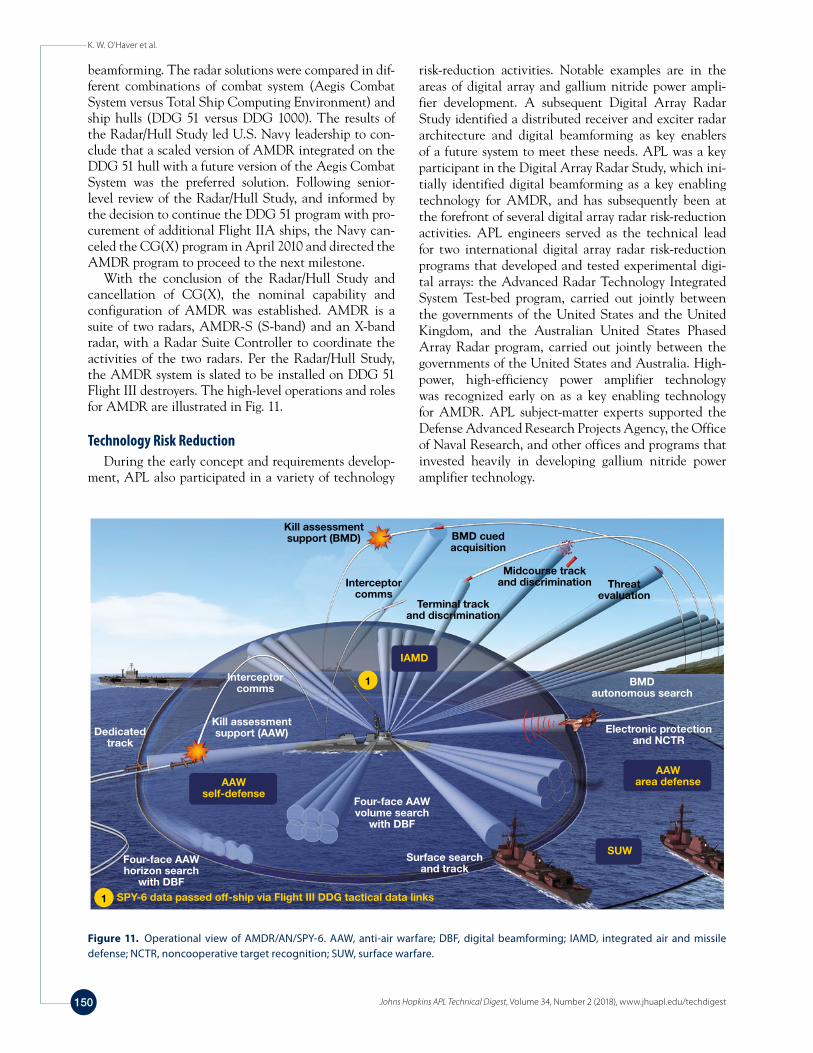
With the conclusion of the Radar/Hull Study and cancellation of CG(X), the nominal capability and configuration of AMDR was established. AMDR is a suite of two radars, AMDR-S (S-band) and an X-band radar, with a Radar Suite Controller to coordinate the activities of the two radars. Per the Radar/Hull Study, the AMDR system is slated to be installed on DDG 51 Flight III destroyers. The high-level operations and roles for AMDR are illustrated in Fig. 11.
Technology Risk ReductionDuring the early concept and requirements develop-
ment, APL also participated in a variety of technology
risk-reduction activities. Notable examples are in the areas of digital array and gallium nitride power ampli-fier development. A subsequent Digital Array Radar Study identified a distributed receiver and exciter radar architecture and digital beamforming as key enablers of a future system to meet these needs. APL was a key participant in the Digital Array Radar Study, which ini-tially identified digital beamforming as a key enabling technology for AMDR, and has subsequently been at the forefront of several digital array radar risk-reduction activities. APL engineers served as the technical lead for two international digital array radar risk-reduction programs that developed and tested experimental digi-tal arrays: the Advanced Radar Technology Integrated System Test-bed program, carried out jointly between the governments of the United States and the United Kingdom, and the Australian United States Phased Array Radar program, carried out jointly between the governments of the United States and Australia. High-power, high-efficiency power amplifier technology was recognized early on as a key enabling technology for AMDR. APL subject-matter experts supported the Defense Advanced Research Projects Agency, the Office of Naval Research, and other offices and programs that invested heavily in developing gallium nitride power amplifier technology.
Kill assessmentsupport (BMD)
Interceptorcomms
BMD cuedacquisition
Threatevaluation
BMDautonomous search
Midcourse trackand discrimination
Electronic protection and NCTR
Interceptor comms
Kill assessmentsupport (AAW)
Four-face AAWvolume search
with DBF
Surface searchand track
SUW
Dedicatedtrack
SPY-6 data passed off-ship via Flight III DDG tactical data links
1
1
AAWself-defense
AAWarea defense
IAMD
Terminal trackand discrimination
Four-face AAWhorizon search
with DBF
Figure 11. Operational view of AMDR/AN/SPY-6. AAW, anti-air warfare; DBF, digital beamforming; IAMD, integrated air and missile defense; NCTR, noncooperative target recognition; SUW, surface warfare.
Radar Development for Air and Missile Defense
Johns Hopkins APL Technical Digest, Volume 34, Number 2 (2018), www.jhuapl.edu/techdigest 151
In the TD phase, the contractors refined system concepts to a sufficient level of detail to allow them to develop specifications and conduct initial preliminary design reviews, all in a competitive environment where each contractor was incentivized to thoroughly explore the cost/performance trade space. The government sys-tems engineering team partnered with each contractor to ensure that the concepts evolved to fully address Navy requirements. The result was a competitive landscape at the time the engineering and manufacturing devel-opment (EMD) request for proposal was released, with three relatively mature designs as a basis for proposal. At this point, the government team had an unprecedented understanding of each of the contractor designs with respect to cost and performance and was well positioned to ensure the best value in the next phase of develop-ment. From the early study phases through the TD phase, APL provided critical contributions to AMDR via leadership roles in system architecture, modeling and simulation, software development, physical and electri-cal ship integration, and testing and evaluation.
In 2014, the AMDR EMD contract was competi-tively awarded to Raytheon Integrated Defense Systems, based in Sudbury, Massachusetts. Coming out of the TD phase, the radar hardware design was relatively mature, with only a few changes planned to components based on the TD phase testing experience. The technologies
AMDR-S DevelopmentThe AMDR program affords a once-in-a-generation
opportunity to develop the complete replacement for the surface Navy’s primary fire control sensor (AN/SPY-1). Recognizing this in 2005, the Office of the Chief of Naval Operations directed the Above Water Sensors Directorate of Program Executive Office Integrated War-fare Systems (PEO IWS 2.0) to begin the long-lead pro-cess of generating top-level radar performance (TLRP) requirements in preparation for a multiphase acquisition program. Given the significant operational demands of the integrated air and missile defense mission, coupled with the cost and implied technology development needs of an advanced maritime radar, PEO IWS 2.0 sponsored a multi-organizational government team, for which APL provided technical leadership in several areas, to develop a government concept architecture. This reference architecture was developed in parallel with the TLRP in order to underpin and justify the feasibility of the requirements being established. Guided by top-level per-formance needs defined by the Maritime Air and Missile Defense of the Joint Forces Analysis of Alternatives and Radar/Hull Study, a top-level architecture concept was synthesized to provide the level of radar performance determined by these past Navy studies. This concept was deemed feasible to implement in modern radar hardware and software architectures, as guided by subject-matter experts from APL and other government laboratories.
The TLRP became the requirements basis for a 6-month competitive concept studies phase in which three U.S. defense prime contractors (Lockheed Martin, Northrop Grumman, and Raytheon) each developed their own radar architecture and design concepts. This concept phase validated the performance goals of the TLRP, with changes only in secondary areas of design concern; provided feedback to industry in areas where their proposed concepts were inconsistent with the requirements; identified and solidified the principal areas of technology development that would be pursued in the subsequent TD phase; and validated that key ship constraints (weight/power/cooling/footprint) were appropriately addressed in each contractor’s concept.
During a subsequent TD phase, each of the three prime contractors were tasked with the following objectives:
• Demonstrate maturity of critical technologies.
• Develop an initial system design to a level sufficient to conduct a preliminary design review.
• Conduct a technology demonstration review to pres-ent test data and analysis of demonstrations.
• Conduct a systems requirements review, system functional review, test readiness review, and a pre-liminary design review.
• Provide a TD prototype.
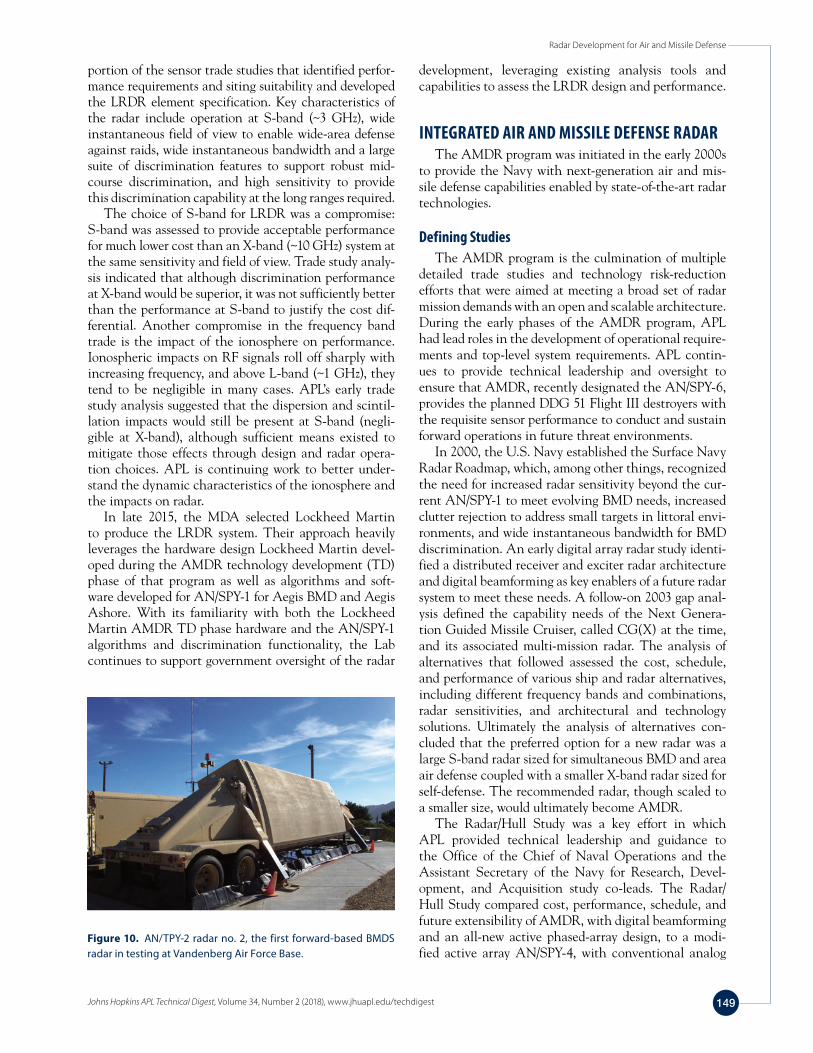
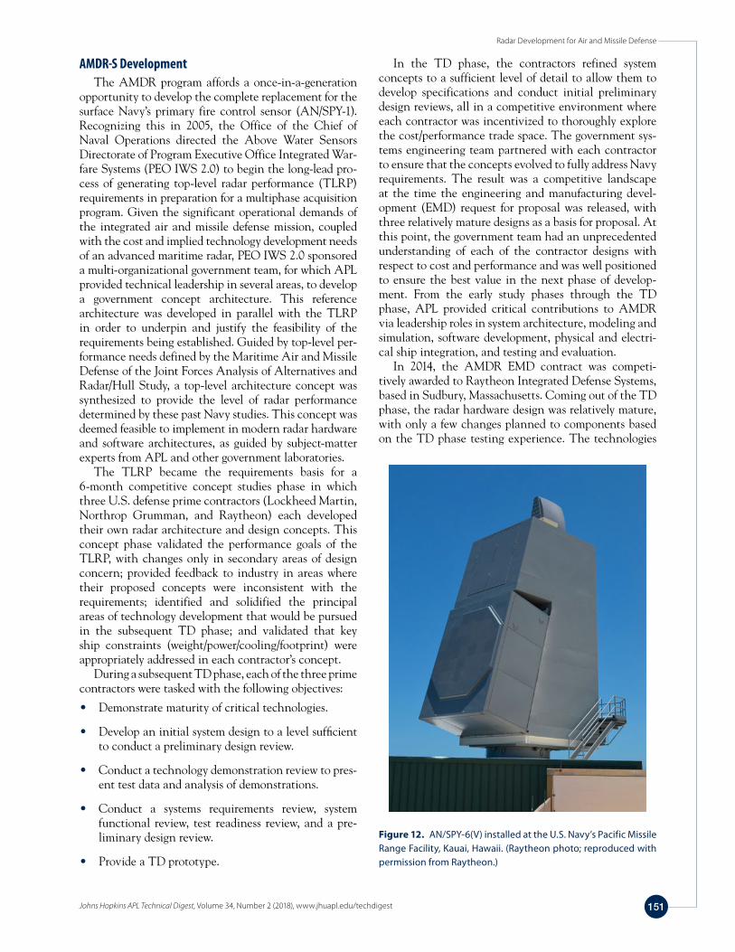
Figure 12. AN/SPY-6(V) installed at the U.S. Navy’s Pacific Missile Range Facility, Kauai, Hawaii. (Raytheon photo; reproduced with permission from Raytheon.)
K. W. O’Haver et al.
Johns Hopkins APL Technical Digest, Volume 34, Number 2 (2018), www.jhuapl.edu/techdigest152
tional multifunction phased-array radar technology of Aegis and concluding with recent technical leadership in the development of the Navy’s new AMDR. Through-out this history, APL has played the roles of innovator, technical advisor, and partner with government and industry to introduce these capabilities. These accom-plishments are the result of a dedicated and technically diverse staff and an adherence to a systems engineer-ing process that includes concept development, devel-opment and application of enabling technology, critical experiments, transition to industry producers, rigorous testing, and evaluation of effectiveness against continu-ing evolving threats. This process continues today with new radar technology and system and system-of-system innovations in development. APL is committed to con-tinued innovation and application of the systems engi-neering perspective and practice to ensure future success in outpacing rapidly evolving threats.
REFERENCES 1Gussow, M., and Prettyman, E. C., “Typhon—A System Ahead of its
Time,” Johns Hopkins APL Tech. Dig. 13(1), 82–89 (1992). 2Frank, J., Shipley, C. A., Grady, H. M., and Kuck, J., “Latching Ferrite
Phase Shifter for Phased Arrays,” Microw. J. 10, 97–102 (1967). 3Frank, J., and O’Haver, K. W., “Phased Array Antenna Development
at the Applied Physics Laboratory,” Johns Hopkins APL Tech. Dig. 14(4), 339–347 (1993).
4Phillips, C. C., “Aegis: Advanced Multi-Function Array Radar,” Johns Hopkins APL Tech. Dig. 2(4), 246–249 (1981).
5Irzinski, E. P., “APL Contributions to Aegis,” Johns Hopkins APL Tech. Dig. 2(4), 250–255 (1981).
6Rottier, J. R., Rowland, J. R., Konstanzer, G. C., Goldhirsh, J., and Dockery, G. D., “APL Environmental Assessment for Naval Anti-Air Warfare,” Johns Hopkins APL Tech. Dig. 22(4), 447–461 (2001).
7Newkirk, M. H., Gehman, J. Z., and Dockery, G. D., “Advances in Calculating Electromagnetic Field Propagation Near the Earth’s Sur-face,” Johns Hopkins APL Tech. Dig. 22(4), 462–472 (2001).
8Sylvester, J. J., Konstanzer, G. C., Rottier, J. R., Dockery, G. D., and Rowland, J. R., “Aegis Anti-Air Warfare Tactical Decision Aids,” Johns Hopkins APL Tech. Dig. 22(4), 473–487 (2001).
9Agrawal, A. K., Kopp, B. A., Luesse, M. H., and O’Haver, K. W., “Active Phased Array Antenna Development for Modern Shipboard Radar Systems,” Johns Hopkins APL Tech. Dig. 22(4), 600–613 (2001).
employed in the design were assessed as being at the required technology readiness level of TRL 6.
APL provided oversight and subject-matter expertise in the development of the AMDR architecture and the associated hardware and software during the AMDR TD phase. In the current EMD phase, APL continues to provide this type of support for government oversight of Raytheon’s agile software development process, algo-rithms development, modeling and simulation (which will be used to sell off many key requirements), cyberse-curity, and ongoing ship integration analysis and designs.
The full AN/SPY-6 engineering development model array has been delivered to and installed at the Advanced Radar Detection Laboratory at the Pacific Missile Range Facility in Kauai, Hawaii (Fig. 12). AMDR-S will undergo demonstration testing at the Advanced Radar Detection Laboratory for all missions during FY2017 before pro-ceeding to ship and combat system integration. Because of the Laboratory’s long, successful history supporting Aegis BMD testing, it has several key responsibilities in the area of BMD flight testing, including target and mis-sion requirements development, trajectory evaluation, radar cross section prediction and measurement, sce-nario planning and analysis, configuration management, materials science and materials application, target-based instrumentation (e.g., imaging sensor payloads) and asso-ciated ground support equipment, terminal target (mock reentry vehicle) prototypes, satellite collision avoidance, and post-mission target trajectory reconstruction.
CONCLUSIONThroughout the Laboratory’s history, its engineers
have played leading roles in developing and evolving advanced radar capabilities to counter ever-advancing air, cruise missile, and ballistic missile threats. This arti-cle highlights some major accomplishments, beginning with the development and prototyping of the founda-
Kenneth W. O’Haver, Air and Missile Defense Sector, Johns Hopkins University Applied Physics Laboratory, Laurel, MD
Kenneth O’Haver is a Principal Profes-sional Staff member and Chief Scientist in the Sensor and Communications Branch in APL’s Air and Missile Defense Sector. He received a B.S. in electrical engineering
from Virginia Tech and an M.S. in electrical engineering from Johns Hopkins University. He has over 30 years of experience in the development of advanced radar systems, communica-tions systems, electronic warfare systems, phased-array anten-nas, and advanced RF technologies. He has published numer-ous technical papers and has presented at various conferences. His e-mail address is [email protected].
Christopher K. Barker, Air and Missile Defense Sector, Johns Hopkins University Applied Physics Laboratory, Laurel, MD
Christopher Barker is a Principal Profes-sional Staff member and program manager in APL’s Air and Missile Defense Sector. He received a B.S. in political science from the United States Naval Academy
and served as a commissioned officer and carrier aviator in the E-2C Hawkeye community. Since joining APL in 2009, he has managed the Air and Missile Defense Radar (AMDR) program and other related advanced Surface Navy radar development initiatives. In 2014, he and teammates were granted the APL Achievement Award for Outstanding Mission Accomplish-ment for their contributions to AMDR capabilities. His e-mail address is [email protected].
Radar Development for Air and Missile Defense
Johns Hopkins APL Technical Digest, Volume 34, Number 2 (2018), www.jhuapl.edu/techdigest 153
G. Daniel Dockery, Air and Missile Defense Sector, Johns Hopkins University Applied Physics Laboratory, Laurel, MD
G. Daniel Dockery is a Principal Profes-sional Staff member and Supervisor of the Sensor and Communication Systems Branch in APL’s Air and Missile Defense Sector. He received a B.S. in physics and an
M.S. in electrical engineering, both from Virginia Tech. He completed coursework in the University of Maryland’s Ph.D. program in electrical engineering. Since joining APL in 1983, Dan has worked in the areas of EM propagation and radar engineering as well as environmental characterization for U.S. Navy radar and communication systems. His e-mail address is [email protected].
James D. Huffaker, Air and Missile Defense Sector, Johns Hopkins University Applied Physics Laboratory, Laurel, MD
James Dodd Huffaker is a Principal Profes-sional Staff member and Assistant Super-visor of the Sensor and Communication Systems Branch in APL’s Air and Missile Defense Sector. He received a B.S. and an
M.S. in electrical engineering, both from Georgia Tech. He has 30 years’ experience in advanced radar system development, analysis, testing, and simulation for the U.S. Navy and Missile Defense Agency, primarily focused on AN/TPY-2, Aegis AN/SPY-1, and AN/SPY-6. His e-mail address is [email protected].