Embed Size (px)
Citation preview

1 © 2013 The MathWorks, Inc.
Radar System Design with
Phased Array System Toolbox
John Zhao
Product Manager

2
Outline
Challenges in Radar System Design
Modeling Pulse Radar System
Modeling FMCW Radar System
Designing Phased Array
Integrating and Prototyping Radar System

3
What is Radar?
TX
RX
Transmitted signal
Echo signal
Delay = position
Doppler shift = speed
Waveform
Generator Transmitter
Signal
Processing Receiver
Environment,
Targets, and
Interference

4
Radar Design Requires Multi-Domain
Expertise and Collaboration
Signal modeling in 3 domains:
– Time domain
– Frequency domain
– Spatial domain
System development in 3 domains:
– Digital Baseband
– Analog/Mixed-Signal
– Radio Frequency
Waveform
Generator Transmitter
Signal
Processing Receiver
Environment,
Targets, and
Interference

5
Design and simulate phased array radar systems
Arrays, waveforms, targets, clutter, etc…
Radar signal processing algorithms
Phased Array System Toolbox
10-10
10-8
10-6
10-4
10-2
100
0
0.1
0.2
0.3
0.4
0.5
0.6
0.7
0.8
0.9
1
SNR=0dB
SNR=3dB
SNR=10dB
SNR=13dB
NonfluctuatingCoherent Receiver Operating Characteristic (ROC) Curves
Pfa
Pd
Angle (degrees)
Norm
aliz
ed D
opple
r F
requency Data Snapshot Angle Doppler Response
-80 -60 -40 -20 0 20 40 60 80-0.5
0
0.5
Pow
er
(dB
)
-100
-80
-60
-40
Angle (degrees)
Norm
aliz
ed D
opple
r F
requency SMI Weights Angle Doppler Response
-80 -60 -40 -20 0 20 40 60 80-0.5
0
0.5
Pow
er
(dB
)
-80
-60
-40
-20
0

6
Outline
Challenges in Radar System Design
Modeling Pulse Radar System
Modeling FMCW Radar System
Designing Phased Array
Integrating and Prototyping Radar System

7
Pulse Radars Applications
Defense:
– Outer space / marine surveillance
– Antimissile / guided missile target locating
Civil:
– Altimetry and flight control
– Air traffic control and aircraft anti-collision
… and more:
– Weather monitoring
– Ground-penetrating radar for geological
observations
– Radar astronomy
Established technology

8
Example: Pulse Ground Radar
Measure distance, speed and direction
DSP

9
What Behavior Can Be Modeled?
Algorithms for
Data Analysis
Waveform design Channel model
(interference, clutter)
Antenna arrays
(size, geometry)
RF impairments
(noise, non-linearity,
frequency dependency)
Target
model

10
Which MathWorks Tools Can Help?
Phased Array System Toolbox
– Waveform design
– Array design
– Radar equation
– Channel model
– Target model
– Detection algorithms
SimRF
– Component noise
– Component Non-linearity
– Carrier frequency selectivity
11
System-Level Block Diagram
Waveform
Generator Transmitter
Signal
Processing Receiver
Environment,
Targets, and
Interference

12
Waveform Generation
Pulsed waveforms – Rectangular pulses
– Linear frequency modulation (LFM) pulses
– Stepped FM pulses
– Staggered PRFs
Phased coded waveform
Continuous waveform (FMCW)
Ambiguity function
0 500 1000 1500 2000 2500 3000 3500 4000 4500 5000-140
-120
-100
-80
-60
-40
-20
0
20Fast Time Sequences Using Staggered PRFs
Range (m)
Pow
er
(dB
)
Before MTI filter
After MTI filter
0 0.2 0.4 0.6 0.8 1 1.2
x 10-4
-1
-0.8
-0.6
-0.4
-0.2
0
0.2
0.4
0.6
0.8
1
Time (s)
Am
plit
ude (
v)
Linear FM Pulse Waveform - Gaussian Envelope (real part, pulse 1)

13
System-Level Block Diagram
Waveform
Generator Transmitter
Signal
Processing Receiver
Environment,
Targets, and
Interference

14
Transmitter
Transmitter – Gain
– Peak power
– Loss factor
– Monostatic and multistatic configurations
Radiators (transmit antennas) – Narrowband signals
– Platform motion
Environment
Radiators
Transmit array = group of radiators
Transmitter

15
Receiver
Collectors (receive antennas) – Narrowband and wideband signals
– Plane and custom wavefront models
– Array shading
– Platform motion
Receiver characteristics – Gain
– Loss factor
– Noise figure
– Reference temperature
– Monostatic and multistatic configurations
Chan (M)
RG
(K
)
Environment
Receiver
Characteristics
Collectors Receive array = group of collectors

16
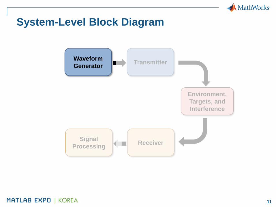
System-Level Block Diagram
Waveform
Generator Transmitter
Signal
Processing Receiver
Environment,
Targets, and
Interference

17
Environment, Targets, and Interference
Environment model
– Free space
– Constant gamma clutter
– Barrage jammer
Target models
– Point target
– Swerling models
– Platform motion
– Polarization
Environment
Target
Interference
19
System-Level Block Diagram
Waveform
Generator Transmitter
Signal
Processing Receiver
Environment,
Targets, and
Interference
RG
(K
)
Chan (M)

20
Temporal Processing
Time varying gain control
Pulse compression and stretch
processing
Coherent, non-coherent integration
Detection − Constant false alarm rate (CFAR)
− ROC curves − Neyman-Pearson detector threshold
− Albersheim and Shnidman equations
Range and Doppler estimation
10-10
10-8
10-6
10-4
10-2
100
0
0.1
0.2
0.3
0.4
0.5
0.6
0.7
0.8
0.9
1
SNR=0dB
SNR=3dB
SNR=10dB
SNR=13dB
NonfluctuatingCoherent Receiver Operating Characteristic (ROC) Curves
Pfa
Pd
0 0.005 0.01 0.015 0.02 0.025 0.03
-300
-280
-260
-240
-220
-200
-180
-160
-140
-120
Time (ms)
Pow
er
(dB
w)
Target Range Estimation

21
Spatial Processing
Digital beamforming
– Narrowband
Conventional
MVDR (Capon)
LCMV
– Broadband
Frost
Time delay
Time delay LCMV
Subband phase shift
Direction of arrival
– Uniform Arrays Sum and difference monopulse
Beamscan, MVDR (Capon)
– Conformal arrays Beamscan, MVDR (Capon)

22
Angle (degrees)N
orm
aliz
ed D
opple
r F
requency Data Snapshot Angle Doppler Response
-80 -60 -40 -20 0 20 40 60 80-0.5
0
0.5
Pow
er
(dB
)
-100
-80
-60
-40
Angle (degrees)
Norm
aliz
ed D
opple
r F
requency SMI Weights Angle Doppler Response
-80 -60 -40 -20 0 20 40 60 80-0.5
0
0.5
Pow
er
(dB
)
-80
-60
-40
-20
0
0 1000 2000 3000 4000 5000 60000
0.005
0.01
0.015
Range (m)
Magnitude
Target
Signals collected by the ULA within the first pulse interval
0 1000 2000 3000 4000 5000 60000
0.5
1
1.5x 10
-6
Target
Range (m)
Magnitude
SMI output
Space-Time Adaptive Processing (STAP)
Displaced phase center array (DPCA)
Adaptive DPCA
Sample matrix inversion (SMI)
Angle-Doppler response

23
Example: Simulate End-to-End Radar System
A complete end-to-end monostatic radar system
Single element transmitter and 3-element array receiver
Multiple targets with various speeds and positions

24
System Design Specification
Probability of detection Pd = 0.9
Probability of false alarm Pfa = 1e-6
Maximum range Rmax = 5000 m
Range resolution DR = 50 m
Center frequency fc = 1 GHz
Targets model non-fluctuating

25
Summary: Design and Simulate Pulse Radar
Build the executable specification
Develop detection algorithms
Validate performance and compliance
Refine component specifications at the system level

26
Outline
Challenges in Radar System Design
Modeling Pulse Radar System
Modeling FMCW Radar System
Designing Phased Array
Integrating and Prototyping Radar System

27
FMCW Radars Applications
Automotive:
– Adaptive cruise control
– Parking sensors
– Traffic control
… and more:
– Weather radar
– Military security (through-wall sensing,
concealed weapon detection)
– Tank level gauging
Emerging trends

28
FMCW Radar for Automotive
The received signal is a delayed copy of the
transmitted signal
Ultra-large signal bandwidth (>100MHz)
Ultra high frequencies (>77GHz)
Car+Radar Target

29
DSP
What Behavior Can Be Modeled?
Algorithms for
Data Analysis
Waveform Design Channel model
(interference, target, noise)
Antenna arrays
(size, geometry)
RF Impairments
(noise, non-linearity,
frequency dependency)

30
Which MathWorks Tools Can Help?
Phased Array System Toolbox
– Waveform design
– Array design
– Radar equation
– Channel model
– Detection algorithms
SimRF
– Component noise
– Component Non-linearity
– Carrier frequency selectivity

31
Summary: Design and Simulate FMCW Radar
Build the executable specification
Develop detection algorithms
Validate performance and compliance
Refine component specifications at the system level

32
Outline
Challenges in Radar System Design
Modeling Pulse Radar System
Modeling FMCW Radar System
Designing Phased Array
Integrating and Prototyping Radar System

33
Phased Array Design
Geometry, layout, and element definition
Array geometry – Uniform array (linear, rectangular)
– Arbitrary geometry (conformal)
Array layout – Number of elements
– Element spacing
– Array shading/tapering
– Subarray
Element definition – Directionality (Isotropic, cosine-weighted, user specified)
– Heterogeneous array
– Polarization

34
Phased Array Analysis and Visualization
Array directivity
Grating lobe diagram
Delay between elements
Steering vector
Non-ideal array

35
Demo: Complex Array Design and Visualization
Arrays and subarrays with complex geometries
Interactive 3D visualization

36
More Examples – Phased Array Gallery

37
Outline
Challenges in Radar System Design
Modeling Pulse Radar System
Modeling FMCW Radar System
Designing Phased Array
Integrating and Prototyping Radar System

38

39
Generate Code for Your Radar Algorithms
Deploy and execute on desktop
Integrate into larger C/C++ based simulations
Target embedded processors or FPGA
iterate
Algorithm Design and
Code Generation in
MATLAB
verify /accelerate

40
Test Algorithms in Corporate Simulators
Generate standalone C/C++ code
Integrate C code into existing test
harness
Run tests in corporate simulator
Tools
– MATLAB Coder
– Simulink Coder

41
More Information
Product Manager:
John Zhao
Technical Presentations:
“Radar System Design and Analysis with MATLAB” http://www.mathworks.com/videos/radar-system-design-and-analysis-with-matlab-81917.html
“Design and Verify RF Transceivers for Radar Systems” http://www.mathworks.com/videos/design-and-verify-rf-transceivers-for-radar-systems-
81990.html
Product Examples
Phased Array System Toolbox
http://www.mathworks.com/products/phased-array