Embed Size (px)
Citation preview


Foreword
FAG Black Series The new radial insert ball bearing and housing units FAG Black Series from Schaeffler give easy mounting, smooth running andhigh reliability and thus allow particularly economical bearing arrangements.
The dimensions of the FAG housings, made from flake graphite cast iron and with a primer paint coating, conform to JIS B 1559. These single piece cast housings can support moderate to high radial and axial loads. The radial insert ball bearings have basic protection against corrosion due to the Durotect®B coating.
The bearing units are particularly suitable for applications with moderate to high loads.
Typical areas of application are:
■ agricultural, construction and mining machinery
■ power transmission and conveying equipment
■ pumps
■ textile, paper and woodworking machinery
■ machines for the food container filling, wood and packaging industry
■ steel industry.
Radial insert ball bearings FAG radial insert ball bearings with a spherical outer ring arebased on deep groove ball bearings 62 and are designed in accordance with JIS B 1558. The outer and inner rings as well asthe flinger shields of the radial insert ball bearings are provided with the Durotect®B coating in order to offer basic protection against corrosion. The Black Series radial insert ball bearings are available with two location methods and one type of seal. They can be relubricated and are particularly easy to install.
Housing unitswith flake graphitecast iron housings
Housing units in accordance with JIS B 1557 comprise FAG flake graphite cast iron housings with a concave bore in which FAG radial insert ball bearings are fitted. These units are matched to each other and are available as plummer block housing units, flanged housing units and take-up housing units.
Radial insert ball bearings with a spherical outer ring, when fittedin housings with a concave bore, can compensate for static misalign-ment of the shaft.
Housing units are supplied with a loose packed lubricationnipple and integrated end cap for the lubrication nipple as well asan Allen key.

2 TPI 219 Schaeffler Technologies
Schaeffler Technologies TPI 219 3
Page
Contents
Radial insert ball bearings......................................................... 4
Housing units ........................................................................... 18
Radial insert ball bearings

Schaeffler Technologies TPI 219 5
Page
Radial insert ball bearings
Product overview Radial insert ball bearings......................................................... 6
Features Anti-corrosion protection .......................................................... 7
Location on shaft ...................................................................... 7
Sealing..................................................................................... 8
Design andsafety guidelines
Compensation of static misalignments...................................... 9
Axial load carrying capacity of location method ......................... 9
Speed limits for radial insert ball bearings................................. 10
Shaft tolerances for radial insert ball bearings........................... 11
Accuracy Standard tolerances of radial insert ball bearings ...................... 11
Radial internal clearance of radial insert ball bearings ............... 12
Dimension tables Radial insert ball bearings with grub screws in inner ring,spherical outer ring................................................................... 14
Radial insert ball bearings with adapter sleeve,spherical outer ring................................................................... 16

6 TPI 219 Schaeffler Technologies
Product overview Radial insert ball bearings
With grub screwsin inner ring
Spherical outer ring
UC
00
01
8FF
C
With adapter sleeve
Spherical outer ring
UK
00
01
8FF
4

Schaeffler Technologies TPI 219 7
Radial insert ball bearings
Features These radial insert ball bearings are based on single row deep groove ball bearings 62 and comprise a solid section outer ring and an inner ring extended on both sides.
The bearings have plastic cages and are sealed on both sidesby single piece seals RSR with a vulcanised seal lip and an outer flinger shield.
The honed raceways of the bearing rings, in conjunctionwith the high ball grade, ensure quiet running and a reduced frictional torque.
The outer ring has a spherical outside surface. In combinationwith a housing matched to the design, bearings with a spherical outer ring can compensate static misalignments of the shaft,see page 9.
The radial insert ball bearings are pregreased and can be relubricated. For this purpose, they have one lubrication hole inthe outer ring. In addition, a ball (anti-rotation ball) offset by 90°is fitted as a retainer and prevents undesirable rotation of the outer ring in the housing cavity if high circumferential forces are present.
Inch size designs The radial insert ball bearings are also available with inch size bore dimensions, see dimension table.
Anti-corrosion protection The inner and outer rings as well as the flinger shieldsof the radial insert ball bearings are provided with the Durotect®B coating in order to offer basic protection against corrosion.
Adapter sleeves have a Durotect®B or phosphate coating.
Location on shaft Radial insert ball bearings are particularly easy to fit and are suitable for drawn shafts with the tolerances h6 to h9.
In the radial insert ball bearings UC, the inner ring is located on the shaft by means of two grub screws offset by 120°, Figure 1, page 8.They are suitable for bearing arrangements with a constant direction of rotation or, under low speed and load, for an alternating direction of rotation.
The grub screws are self-retaining and have a fine pitch thread with cup point for secure location of the bearings. In order to allow better differentiation, the metric grub screws have a Durotect®B coating while the inch size grub screws are zinc plated.
In the radial insert ball bearings UK, the inner ring is located onthe shaft by means of a concentric adapter sleeve, Figure 2, page 8.They are suitable for bearing arrangements with an alternating direction of rotation, even under high speed and load.

8 TPI 219 Schaeffler Technologies
Radial insert ball bearings
Tightening torques Tightening torques for metric and inch size grub screws,see table, page 29.Tightening torques for locknuts, see table, page 29.
Sealing FAG Black Series radial insert ball bearings are supplied with seals RSR, see table.
Seal types
UC
Figure 1Location by grub screws
in the inner ring 00
01
81
19
UK
Figure 2Location by adapter sleeve 0
00
19
35
E
Seal RSR
Single piece, zinc-plated sheet steel washerwith vulcanised and radially preloaded seal lipmade from NBR and additional flinger shield0
00
18
11
A
Schaeffler Technologies TPI 219 9
Design andsafety guidelines
Compensationof static misalignments
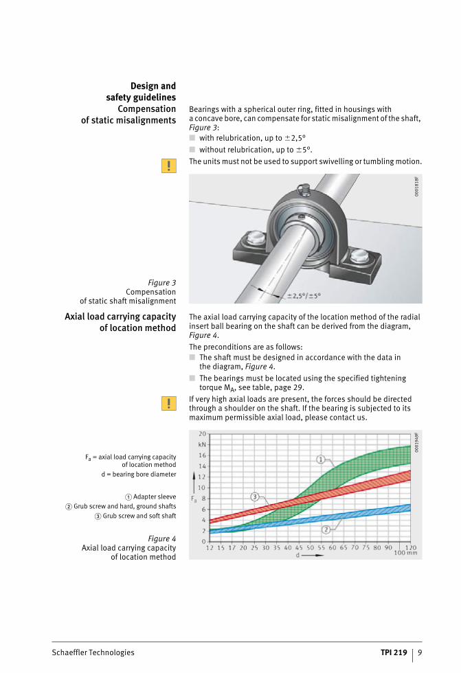
Bearings with a spherical outer ring, fitted in housings witha concave bore, can compensate for static misalignment of the shaft, Figure 3:
■ with relubrication, up to �2,5°
■ without relubrication, up to �5°.
The units must not be used to support swivelling or tumbling motion.
Axial load carrying capacityof location method
The axial load carrying capacity of the location method of the radial insert ball bearing on the shaft can be derived from the diagram, Figure 4.
The preconditions are as follows:
■ The shaft must be designed in accordance with the data inthe diagram, Figure 4.
■ The bearings must be located using the specified tightening torque MA, see table, page 29.
If very high axial loads are present, the forces should be directed through a shoulder on the shaft. If the bearing is subjected to its maximum permissible axial load, please contact us.
Figure 3Compensation
of static shaft misalignment
00
01
81
8F
Fa = axial load carrying capacityof location method
d = bearing bore diameter
� Adapter sleeve
� Grub screw and hard, ground shafts
� Grub screw and soft shaft
Figure 4Axial load carrying capacity
of location method
00
01
94
9F
10 TPI 219 Schaeffler Technologies
Radial insert ball bearings
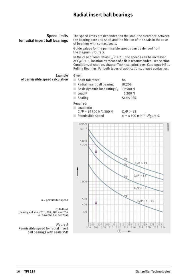
Speed limitsfor radial insert ball bearings
The speed limits are dependent on the load, the clearance between the bearing bore and shaft and the friction of the seals in the caseof bearings with contact seals.
Guide values for the permissible speeds can be derived fromthe diagram, Figure 5.
In the case of load ratios Cr/P � 13, the speeds can be increased.At Cr/P � 5, location by means of a fit is recommended, see section Conditions of rotation, chapter Technical principles, Catalogue HR 1, Rolling Bearings. For both types of applications, please contact us.
Exampleof permissible speed calculation
Given:
Required:
■ Shaft tolerance h6
■ Radial insert ball bearing UC206
■ Basic dynamic load rating Cr 19 500 N
■ Load P 1 300 N
■ Sealing Seals RSR.
■ Load ratioCr/P = 19 500 N/1300 N Cr/P � 13
■ Permissible speed n � 4 300 min–1, Figure 5.
n = permissible speed
� Ball set(bearings of sizes 201, 202, 203 and 204
all have the ball set 204)
Figure 5Permissible speed for radial insert
ball bearings with seals RSR
00
01
95
0D
Schaeffler Technologies TPI 219 11
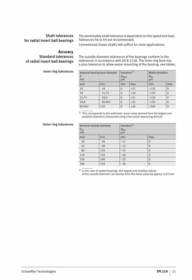
Shaft tolerancesfor radial insert ball bearings
The permissible shaft tolerance is dependent on the speed and load. Tolerances h6 to h9 are recommended.
Conventional drawn shafts will suffice for most applications.
AccuracyStandard tolerances
of radial insert ball bearingsThe outside diameter tolerances of the bearings conform to the tolerances in accordance with JIS B 1558. The inner ring bore hasa plus tolerance to allow easier mounting of the bearing, see tables.
Inner ring tolerances
1) This corresponds to the arithmetic mean value derived from the largest and smallest diameters (measured using a two-point measuring device).
Outer ring tolerances
1) In the case of sealed bearings, the largest and smallest valuesof the outside diameter can deviate from the mean value by approx. 0,03 mm.
Nominal bearing bore diameter Variation1) Width deviationd �dmp �Bsmm �m �m
over incl. min. max. min. max.
10 18 0 +15 –120 0
18 31,75 0 +18 –120 0
31,75 50,8 0 +21 –120 0
50,8 80,962 0 +24 –150 0
80,962 120 0 +28 –200 0
Nominal outside diameter Variation1)
Dsp �Dmmm �m
over incl. min. max.
30 50 –11 0
50 80 –13 0
80 120 –15 0
120 150 –18 0
150 180 –25 0
180 250 –30 0
12 TPI 219 Schaeffler Technologies
Radial insert ball bearings
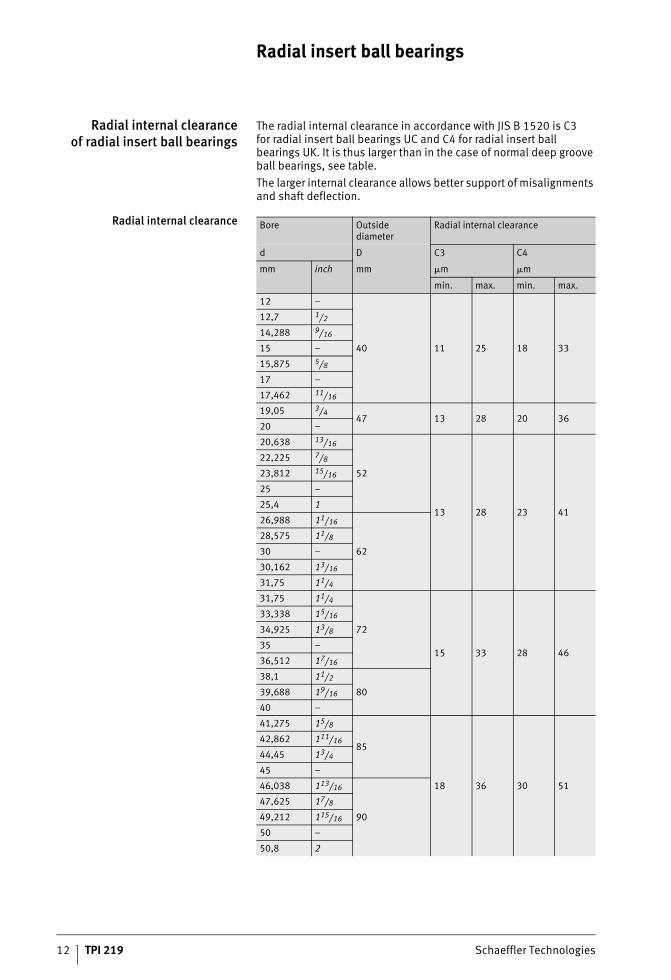
Radial internal clearanceof radial insert ball bearings
The radial internal clearance in accordance with JIS B 1520 is C3for radial insert ball bearings UC and C4 for radial insert ball bearings UK. It is thus larger than in the case of normal deep groove ball bearings, see table.
The larger internal clearance allows better support of misalignments and shaft deflection.
Radial internal clearance Bore Outside diameter
Radial internal clearance
d D C3 C4
mm inch mm �m �m
min. max. min. max.
12 –
40 11 25 18 33
12,7 1/2
14,288 9/16
15 –
15,875 5/8
17 –
17,462 11/16
19,05 3/447 13 28 20 36
20 –
20,638 13/16
52
13 28 23 41
22,225 7/8
23,812 15/16
25 –
25,4 1
26,988 11/16
62
28,575 11/8
30 –
30,162 13/16
31,75 11/4
31,75 11/4
72
15 33 28 46
33,338 15/16
34,925 13/8
35 –
36,512 17/16
38,1 11/2
8039,688 19/16
40 –
41,275 15/8
85
18 36 30 51
42,862 111/16
44,45 13/4
45 –
46,038 113/16
90
47,625 17/8
49,212 115/16
50 –
50,8 2
Schaeffler Technologies TPI 219 13
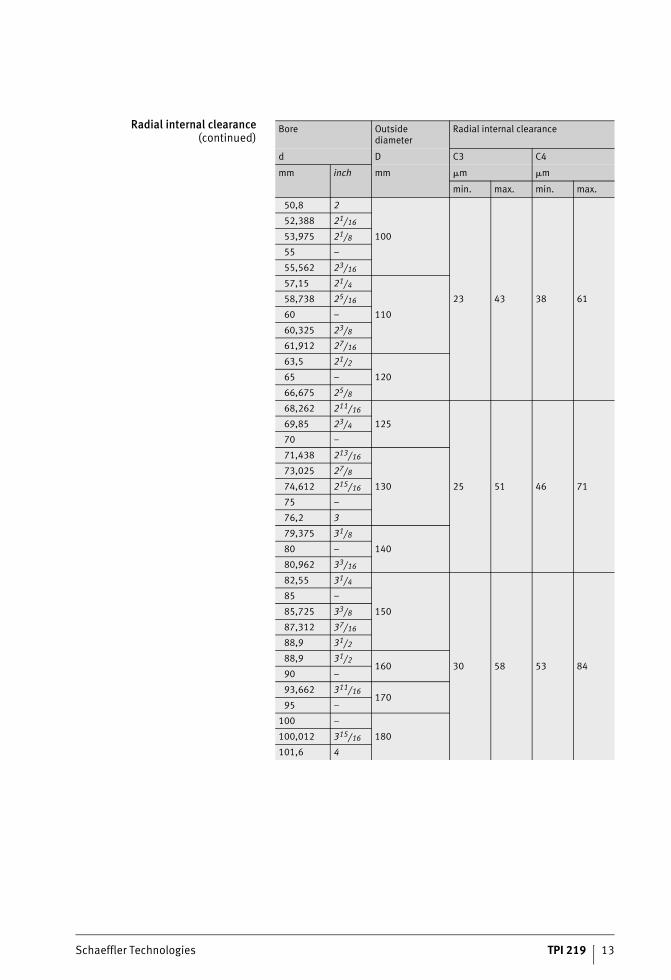
Radial internal clearance(continued)
Bore Outside diameter
Radial internal clearance
d D C3 C4
mm inch mm �m �m
min. max. min. max.
50,8 2
100
23 43 38 61
52,388 21/16
53,975 21/8
55 –
55,562 23/16
57,15 21/4
110
58,738 25/16
60 –
60,325 23/8
61,912 27/16
63,5 21/2
12065 –
66,675 25/8
68,262 211/16
125
25 51 46 71
69,85 23/4
70 –
71,438 213/16
130
73,025 27/8
74,612 215/16
75 –
76,2 3
79,375 31/8
14080 –
80,962 33/16
82,55 31/4
150
30 58 53 84
85 –
85,725 33/8
87,312 37/16
88,9 31/2
88,9 31/2160
90 –
93,662 311/16170
95 –
100 –
180100,012 315/16
101,6 4
14 TPI 219 Schaeffler Technologies
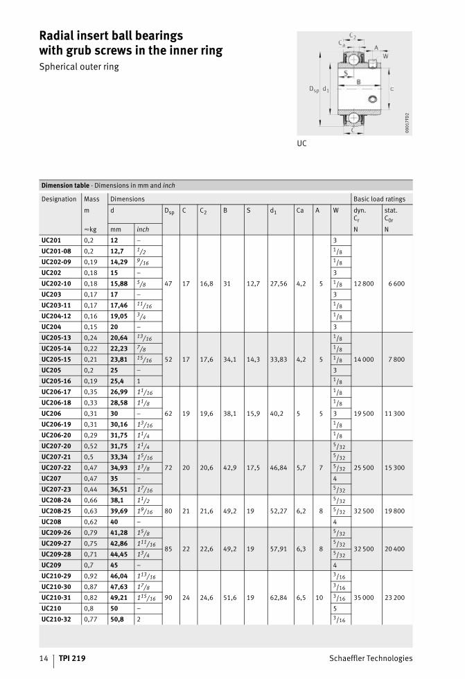
Radial insert ball bearingswith grub screws in the inner ringSpherical outer ring
UC
00
01
7FD
2
Dimension table · Dimensions in mm and inch
Designation Mass Dimensions Basic load ratings
m d Dsp C C2 B S d1 Ca A W dyn.Cr
stat.C0r
�kg mm inch N N
UC201 0,2 12 –
47 17 16,8 31 12,7 27,56 4,2 5
3
12 800 6 600
UC201-08 0,2 12,7 1/2 1/8
UC202-09 0,19 14,29 9/16 1/8
UC202 0,18 15 – 3
UC202-10 0,18 15,88 5/8 1/8
UC203 0,17 17 – 3
UC203-11 0,17 17,46 11/16 1/8
UC204-12 0,16 19,05 3/4 1/8
UC204 0,15 20 – 3
UC205-13 0,24 20,64 13/16
52 17 17,6 34,1 14,3 33,83 4,2 5
1/8
14 000 7 800
UC205-14 0,22 22,23 7/8 1/8
UC205-15 0,21 23,81 15/16 1/8
UC205 0,2 25 – 3
UC205-16 0,19 25,4 1 1/8
UC206-17 0,35 26,99 11/16
62 19 19,6 38,1 15,9 40,2 5 5
1/8
19 500 11 300
UC206-18 0,33 28,58 11/8 1/8
UC206 0,31 30 – 3
UC206-19 0,31 30,16 13/16 1/8
UC206-20 0,29 31,75 11/4 1/8
UC207-20 0,52 31,75 11/4
72 20 20,6 42,9 17,5 46,84 5,7 7
5/32
25 500 15 300
UC207-21 0,5 33,34 15/16 5/32
UC207-22 0,47 34,93 13/8 5/32
UC207 0,47 35 – 4
UC207-23 0,44 36,51 17/16 5/32
UC208-24 0,66 38,1 11/2
80 21 21,6 49,2 19 52,27 6,2 8
5/32
32 500 19 800UC208-25 0,63 39,69 19/16 5/32
UC208 0,62 40 – 4
UC209-26 0,79 41,28 15/8
85 22 22,6 49,2 19 57,91 6,3 8
5/32
32 500 20 400UC209-27 0,75 42,86 111/16 5/32
UC209-28 0,71 44,45 13/4 5/32
UC209 0,7 45 – 4
UC210-29 0,92 46,04 113/16
90 24 24,6 51,6 19 62,84 6,5 10
3/16
35 000 23 200
UC210-30 0,87 47,63 17/8 3/16
UC210-31 0,82 49,21 115/16 3/16
UC210 0,8 50 – 5
UC210-32 0,77 50,8 2 3/16

Schaeffler Technologies TPI 219 15
Radial insert ball bearingswith grub screws in the inner ringSpherical outer ring
UC
00
01
7FD
2
Dimension table (continued) · Dimensions in mm and inch
Designation Mass Dimensions Basic load ratings
m d Dsp C C2 B S d1 Ca A W dyn.Cr
stat.C0r
�kg mm inch N N
UC211-32 1,22 50,8 2
100 25 25,6 55,6 22,2 69,77 7 10
3/16
43 500 29 000
UC211-33 1,17 52,39 21/16 3/16
UC211-34 1,11 53,98 21/8 3/16
UC211 1,07 55 – 5
UC211-35 1,05 55,56 23/16 3/16
UC212-36 1,62 57,15 21/4
110 27 27,6 65,1 25,4 76,48 7,4 10
3/16
52 000 36 000
UC212-37 1,55 58,74 25/16 3/16
UC212 1,49 60 – 5
UC212-38 1,48 60,33 23/8 3/16
UC212-39 1,4 61,91 27/16 3/16
UC213-40 1,82 63,5 21/2
120 28 29,4 65,1 25,4 80,85 8,2 12
1/4
57 000 40 000UC213 1,73 65 – 6
UC213-41 1,72 65,09 29/16 1/4
UC214-42 2,17 66,68 25/8
125 30 31,4 74,6 30,2 85,2 8,5 12
1/4
62 000 44 000UC214-43 2,07 68,26 211/16 1/4
UC214-44 1,97 69,85 23/4 1/4
UC214 1,97 70 – 6
UC215-45 2,38 71,44 213/16
130 32 33,4 77,8 33,3 90 8,5 12
1/4
62 000 44 500
UC215-46 2,27 73,03 27/8 1/4
UC215-47 2,16 74,61 215/16 1/4
UC215 2,13 75 – 6
UC215-48 2,05 76,2 3 1/4
UC216-49 2,88 77,79 31/16
140 33 34,4 82,6 33,3 97 9,3 14
1/4
72 000 54 000UC216-50 2,76 79,38 31/8 1/4
UC216 2,71 80 – 6
UC216-51 2,63 80,96 33/16 1/4
UC217-52 3,8 82,55 31/4
150 35 36,4 85,7 34,1 104,09 10 14
1/4
88 000 64 000UC217-53 3,64 84,14 35/16 1/4
UC217 3,56 85 – 6
UC217-55 3,33 87,31 37/16 1/4
UC218-56 4,19 88,9 31/2160 38 39,4 96 39,7 109,4 11 15
1/496 000 72 000
UC218 4,08 90 – 6
16 TPI 219 Schaeffler Technologies
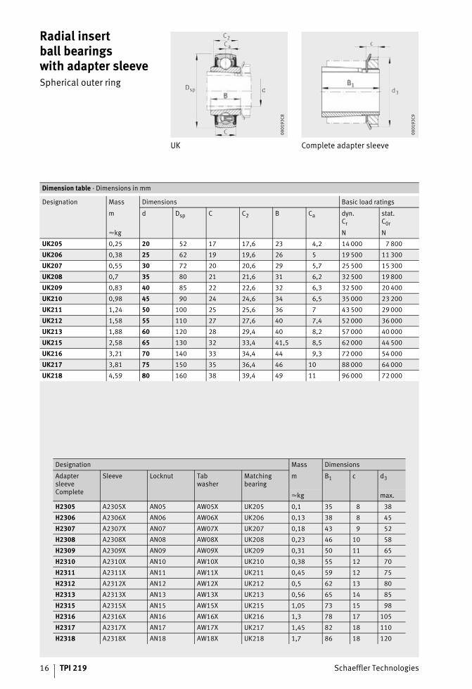
Radial insertball bearingswith adapter sleeveSpherical outer ring
UK Complete adapter sleeve
00
01
93
C8
00
01
93
C9
Dimension table · Dimensions in mm
Designation Mass Dimensions Basic load ratings
m d Dsp C C2 B Ca dyn.Cr
stat.C0r
�kg N N
UK205 0,25 20 52 17 17,6 23 4,2 14 000 7 800
UK206 0,38 25 62 19 19,6 26 5 19 500 11 300
UK207 0,55 30 72 20 20,6 29 5,7 25 500 15 300
UK208 0,7 35 80 21 21,6 31 6,2 32 500 19 800
UK209 0,83 40 85 22 22,6 32 6,3 32 500 20 400
UK210 0,98 45 90 24 24,6 34 6,5 35 000 23 200
UK211 1,24 50 100 25 25,6 36 7 43 500 29 000
UK212 1,58 55 110 27 27,6 40 7,4 52 000 36 000
UK213 1,88 60 120 28 29,4 40 8,2 57 000 40 000
UK215 2,58 65 130 32 33,4 41,5 8,5 62 000 44 500
UK216 3,21 70 140 33 34,4 44 9,3 72 000 54 000
UK217 3,81 75 150 35 36,4 46 10 88 000 64 000
UK218 4,59 80 160 38 39,4 49 11 96 000 72 000
Designation Mass Dimensions
Adapter sleeveComplete
Sleeve Locknut Tabwasher
Matchingbearing
m B1 c d3
�kg max.
H2305 A2305X AN05 AW05X UK205 0,1 35 8 38
H2306 A2306X AN06 AW06X UK206 0,13 38 8 45
H2307 A2307X AN07 AW07X UK207 0,18 43 9 52
H2308 A2308X AN08 AW08X UK208 0,23 46 10 58
H2309 A2309X AN09 AW09X UK209 0,31 50 11 65
H2310 A2310X AN10 AW10X UK210 0,38 55 12 70
H2311 A2311X AN11 AW11X UK211 0,45 59 12 75
H2312 A2312X AN12 AW12X UK212 0,5 62 13 80
H2313 A2313X AN13 AW13X UK213 0,56 65 14 85
H2315 A2315X AN15 AW15X UK215 1,05 73 15 98
H2316 A2316X AN16 AW16X UK216 1,3 78 17 105
H2317 A2317X AN17 AW17X UK217 1,45 82 18 110
H2318 A2318X AN18 AW18X UK218 1,7 86 18 120

Schaeffler Technologies TPI 219 17
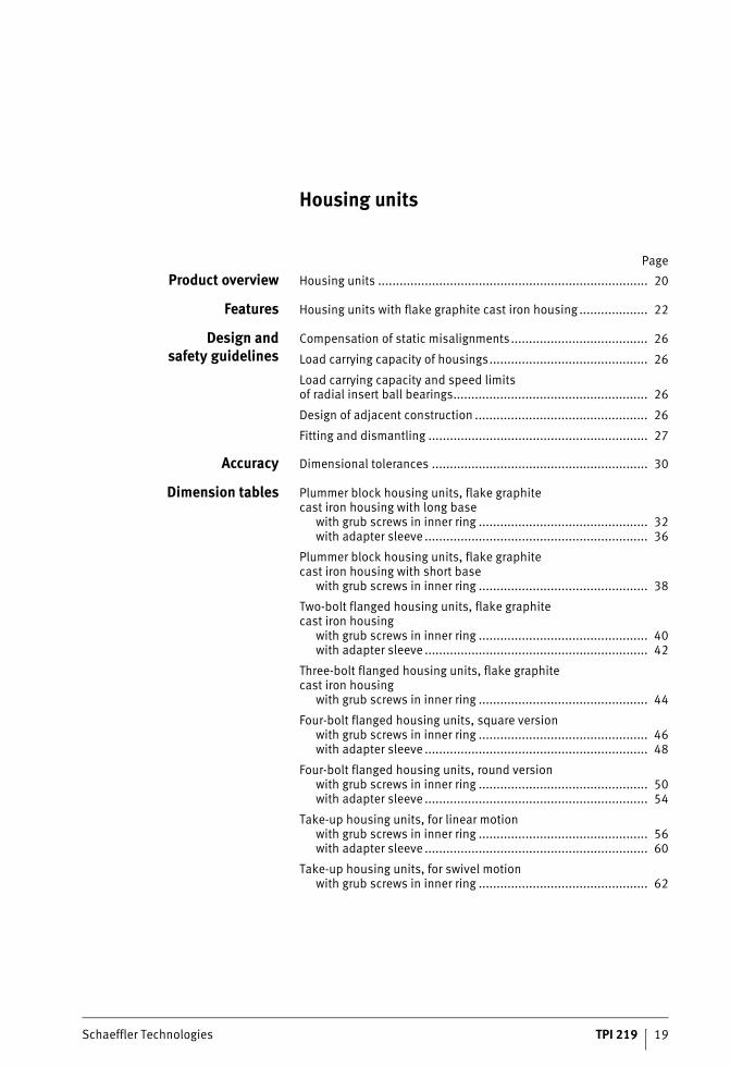
Housing units
Schaeffler Technologies TPI 219 19
Page
Housing units
Product overview Housing units ........................................................................... 20
Features Housing units with flake graphite cast iron housing ................... 22
Design andsafety guidelines
Compensation of static misalignments...................................... 26
Load carrying capacity of housings............................................ 26
Load carrying capacity and speed limitsof radial insert ball bearings...................................................... 26
Design of adjacent construction ................................................ 26
Fitting and dismantling ............................................................. 27
Accuracy Dimensional tolerances ............................................................ 30
Dimension tables Plummer block housing units, flake graphitecast iron housing with long base
with grub screws in inner ring ............................................... 32with adapter sleeve .............................................................. 36
Plummer block housing units, flake graphitecast iron housing with short base
with grub screws in inner ring ............................................... 38
Two-bolt flanged housing units, flake graphitecast iron housing
with grub screws in inner ring ............................................... 40with adapter sleeve .............................................................. 42
Three-bolt flanged housing units, flake graphitecast iron housing
with grub screws in inner ring ............................................... 44
Four-bolt flanged housing units, square versionwith grub screws in inner ring ............................................... 46with adapter sleeve .............................................................. 48
Four-bolt flanged housing units, round versionwith grub screws in inner ring ............................................... 50with adapter sleeve .............................................................. 54
Take-up housing units, for linear motionwith grub screws in inner ring ............................................... 56with adapter sleeve .............................................................. 60
Take-up housing units, for swivel motionwith grub screws in inner ring ............................................... 62
20 TPI 219 Schaeffler Technologies
Product overview Housing units
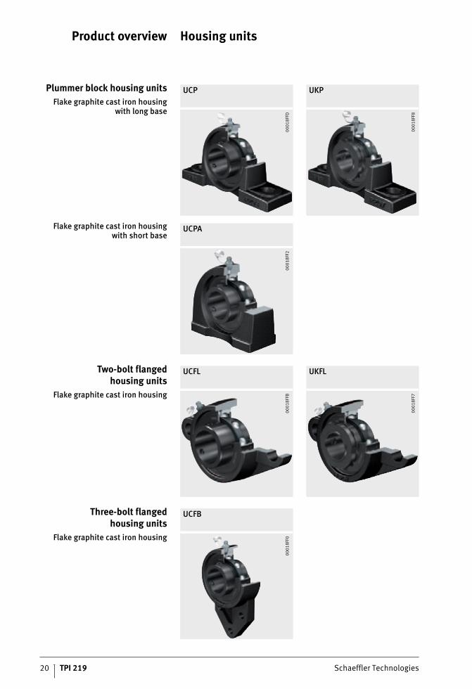
Plummer block housing units
Flake graphite cast iron housingwith long base
UCP UKP
00
01
8FF
D
00
01
8FF
8
Flake graphite cast iron housingwith short base
UCPA
00
01
8FF
2
Two-bolt flangedhousing units
Flake graphite cast iron housing
UCFL UKFL
00
01
8FF
B
00
01
8FF
7
Three-bolt flangedhousing units
Flake graphite cast iron housing
UCFB
00
01
8FF
0
Schaeffler Technologies TPI 219 21
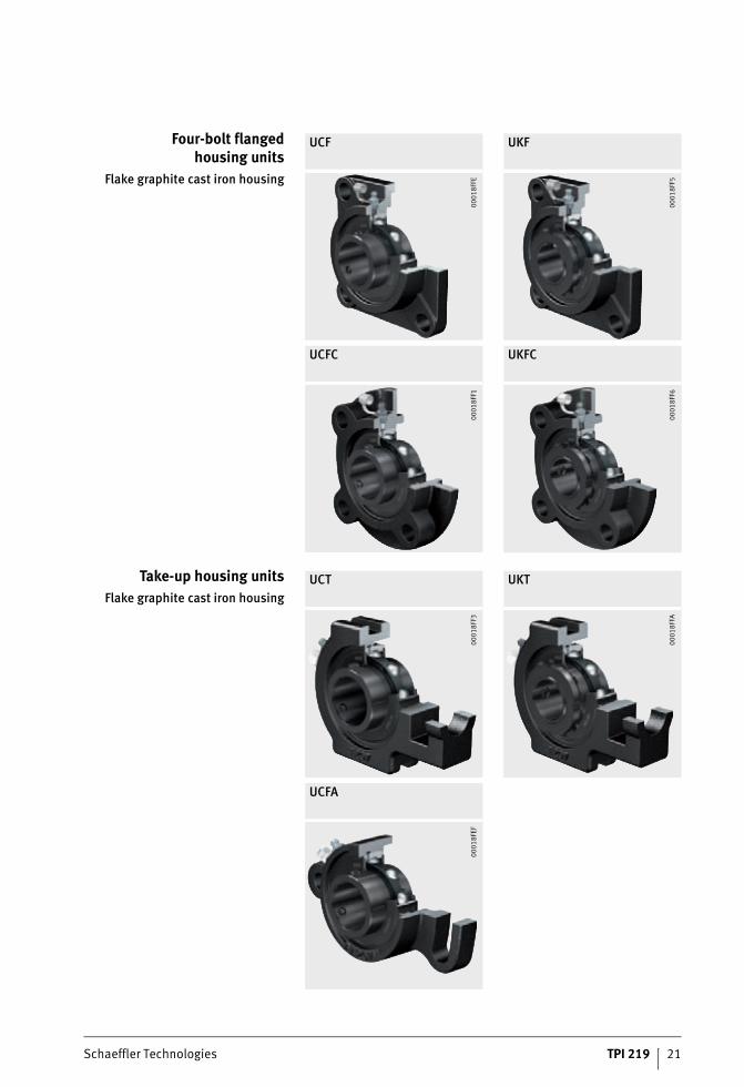
Four-bolt flangedhousing units
Flake graphite cast iron housing
UCF UKF
UCFC UKFC
00
01
8FF
E
00
01
8FF
5
00
01
8FF
1
00
01
8FF
6
Take-up housing units
Flake graphite cast iron housing
UCT UKT
UCFA
00
01
8FF
3
00
01
8FF
A
00
01
8FE
F
22 TPI 219 Schaeffler Technologies
Housing units
Features These housing units are available as plummer block housing units, flanged housing units and take-up housing units. The units are ready-to-fit and comprise FAG flake graphite cast iron housings in which FAG Black Series radial insert ball bearings are fitted. In order to ensure function and reliability under all operating conditions,the bearings and housings are matched to each other.
Due to the spherical outer ring of the bearing and the concave housing bore, housing units can compensate for static misalign-ments of the shaft, see page 26.
The housings are screw mounted on the adjacent construction.Less stringent tolerances are sufficient for the screw mounting surfaces, see page 26.
Housing unitswith flake graphite
cast iron housing
The flake graphite cast iron housings are single piece componentsin accordance with JIS B 1559 and have high radial and axial load carrying capacity, see page 26.
The housing has a lubrication groove for relubrication of the radial insert ball bearing. The housing has a lubrication hole with an M6 thread for a lubrication nipple.
The housings have a primer paint coating as anti-corrosion protection of colour RAL 9005 (black).
Housing material The material used for the flake graphite cast iron housings is cast iron in accordance with JIS G 5501.
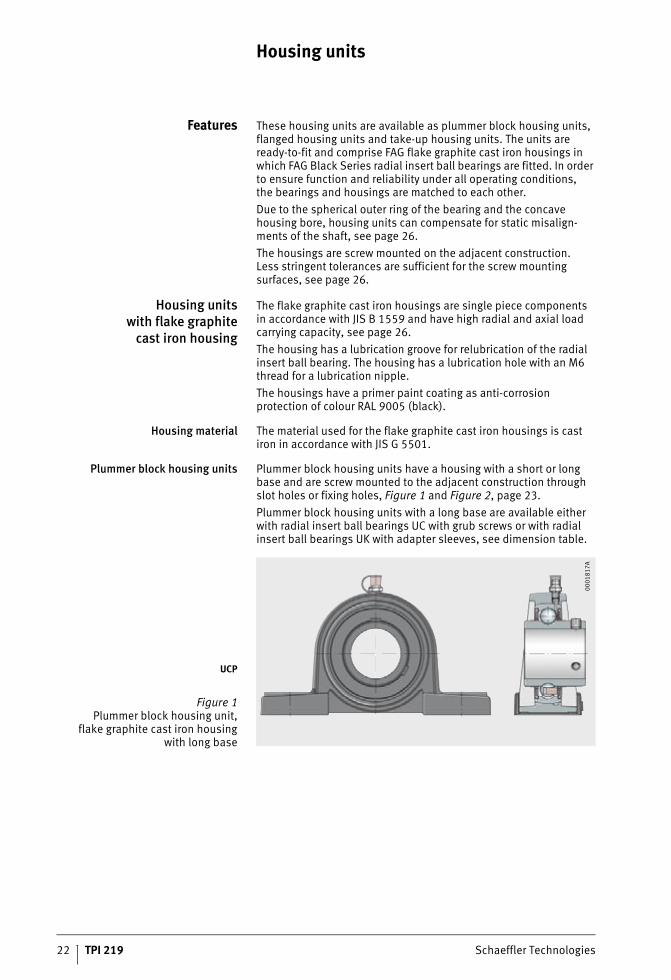
Plummer block housing units Plummer block housing units have a housing with a short or long base and are screw mounted to the adjacent construction through slot holes or fixing holes, Figure 1 and Figure 2, page 23.
Plummer block housing units with a long base are available either with radial insert ball bearings UC with grub screws or with radial insert ball bearings UK with adapter sleeves, see dimension table.
UCP
Figure 1Plummer block housing unit,
flake graphite cast iron housingwith long base
00
01
81
7A
Schaeffler Technologies TPI 219 23
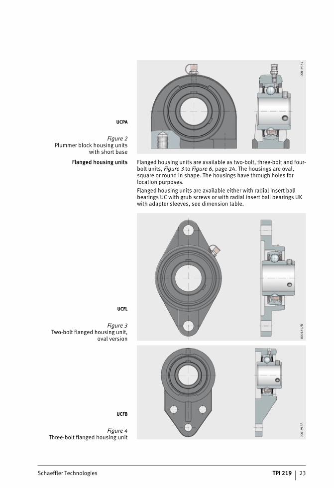
Flanged housing units Flanged housing units are available as two-bolt, three-bolt and four-bolt units, Figure 3 to Figure 6, page 24. The housings are oval, square or round in shape. The housings have through holes for location purposes.
Flanged housing units are available either with radial insert ball bearings UC with grub screws or with radial insert ball bearings UK with adapter sleeves, see dimension table.
UCPA
Figure 2Plummer block housing units
with short base
00
01
93
85
UCFL
Figure 3Two-bolt flanged housing unit,
oval version 00
01
81
7B
UCFB
Figure 4Three-bolt flanged housing unit 0
00
19
4B
A
24 TPI 219 Schaeffler Technologies
Housing units
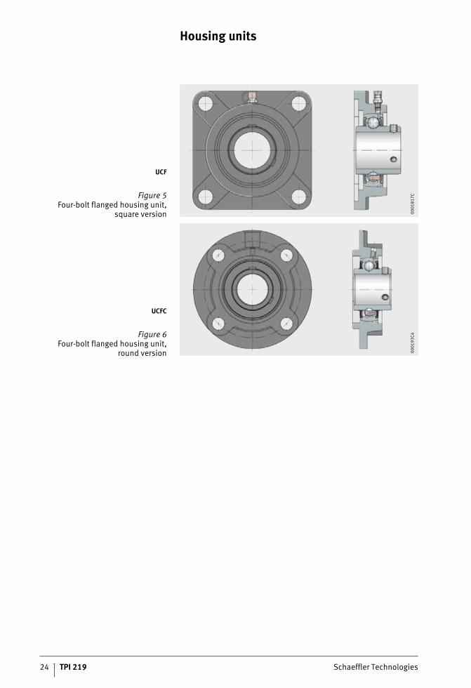
UCF
Figure 5Four-bolt flanged housing unit,
square version 00
01
81
7C
UCFC
Figure 6Four-bolt flanged housing unit,
round version 00
01
93
C4

Schaeffler Technologies TPI 219 25
Take-up housing units Take-up housing units can be moved or swivelled, Figure 7 and Figure 8. They are used where shafts must carry out long displacement motions.
UCT
Figure 7Take-up housing unit
for linear motion 00
01
95
0F
UCFA
Figure 8Take-up housing unit
for swivel motion 00
01
95
11
26 TPI 219 Schaeffler Technologies
Housing units
Design andsafety guidelines
Compensationof static misalignments
Units with a spherical outer ring and concave housing bore can compensate static misalignments of the shaft, see page 9.
Load carrying capacity
of housings
Due to their versatile characteristics, FAG housing units can be easily used in almost all industrial sectors.
Radial load carrying capacity Flake graphite cast iron housings can support the same radial loads as the insert bearings fitted. The static load carrying capacity C0rof the radial insert ball bearings is stated in the dimension tables.
Where shock loads are present, appropriate safety factors must be applied. In this case, please contact us.
Axial load carrying capacity The axial load carrying capacity of flake graphite cast iron housings is restricted to 0,5�C0r.
Load carrying capacity andspeed limits of radial insert
ball bearingsIn the design of housing units, attention must be paid to the load carrying capacity and speed limits of the radial insert ball bearings fitted:
■ axial load carrying capacity, see page 9
■ speed limits, see page 10
■ dimension table, see page 14.
Designof adjacent construction
The permissible shaft tolerance is dependent on the speed and load. Shafts in the tolerance zone h6 to h9 can be used.
Screw mounting surfaces Recommendations for the screw mounting surfaces are as follows:
■ roughness of the screw mounting surface max. Ra12,5 (Rz63)
■ geometrical tolerance 0,04/100 concave,spherical not permissible
■ In addition, it is recommended that the housings should be secured by dowels to the locating surface if higher loads acting parallel to the locating surface occur.
Fixing screws The screw connection should be designed in accordance withthe state of the art. Screws of grade 8.8 can be used. The maximum tightening torques applicable to this screw grade must not be exceeded even if screws of a higher grade are used.
In principle, we recommend that the screw connection should only be tightened to 70% of the values stated in the standard.
Screws and accessories for location are not included in the delivery.
Schaeffler Technologies TPI 219 27
Fitting and dismantling Radial insert ball bearings must be handled with care before and during mounting. Their trouble-free operation is also dependent on the care taken during fitting.
Delivered condition The housings have a coating of black primer paint (RAL 9005).
The radial insert ball bearings are greased using a grease in grease group GA13, see Catalogue HR 1, Rolling Bearings.
The housing units are supplied with a loose packed lubrication nipple and integrated end cap for the lubrication nipple as well asan Allen key.
Storage and shelf life The units should be stored in dry, clean rooms with a temperature as constant as possible and at a relative humidity of max. 65%.
The storage life of radial insert ball bearings is limited by the shelf life of the grease, see chapter Technical principles in Catalogue HR 1, Rolling Bearings.
Removal from packaging Perspiration causes corrosion. Hands must therefore be keptclean and dry. Bearings should not be removed from their original packaging until immediately before fitting.
Preparation for fitting The following preparatory measures for fitting should be taken:
■ Ensure that the fitting tools and fixing screws are present.
■ Clean the shaft and remove any burrs.
■ Inspect the bearing seating surfaces on the shaft.
■ Keep bearing seating surfaces clean, dry and free of grease.
28 TPI 219 Schaeffler Technologies
Housing units
Fitting of plummer block andflanged housing units
The assembly area should be as dry and clean as possible:
■ The specified shaft tolerances must be observed, see page 26.
■ Fitting forces must never be directed through the rolling elements.
■ Blows should never be applied directly to the bearing rings and flinger shields or seals.
■ Observe the tightening torques MA for grub screws and adapter sleeve, see tables, page 29.
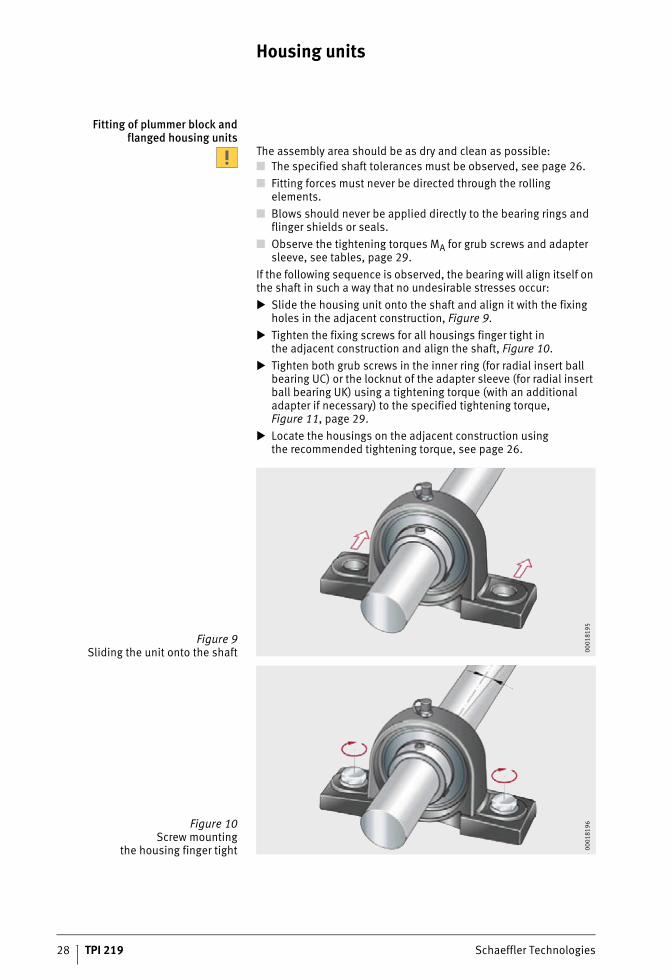
If the following sequence is observed, the bearing will align itself on the shaft in such a way that no undesirable stresses occur:
Slide the housing unit onto the shaft and align it with the fixing holes in the adjacent construction, Figure 9.
Tighten the fixing screws for all housings finger tight inthe adjacent construction and align the shaft, Figure 10.
Tighten both grub screws in the inner ring (for radial insert ball bearing UC) or the locknut of the adapter sleeve (for radial insert ball bearing UK) using a tightening torque (with an additional adapter if necessary) to the specified tightening torque, Figure 11, page 29.
Locate the housings on the adjacent construction usingthe recommended tightening torque, see page 26.
Figure 9Sliding the unit onto the shaft 0
00
18
19
5
Figure 10Screw mounting
the housing finger tight 00
01
81
96
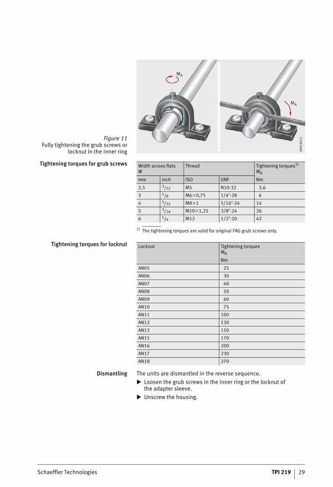
Schaeffler Technologies TPI 219 29
Tightening torques for grub screws
1) The tightening torques are valid for original FAG grub screws only.
Tightening torques for locknut
Dismantling The units are dismantled in the reverse sequence.
Loosen the grub screws in the inner ring or the locknut ofthe adapter sleeve.
Unscrew the housing.
Figure 11Fully tightening the grub screws or
locknut in the inner ring 00
01
94
52
Width across flatsW
Thread Tightening torques1)
MA
mm inch ISO UNF Nm
2,5 3/32 M5 N10-32 3,6
3 1/8 M6�0,75 1/4�-28 6
4 5/32 M8�1 5/16�-24 14
5 3/16 M10�1,25 3/8�-24 26
6 1/4 M12 1/2�-20 42
Locknut Tightening torquesMA
Nm
AN05 25
AN06 30
AN07 40
AN08 50
AN09 60
AN10 75
AN11 100
AN12 130
AN13 150
AN15 170
AN16 200
AN17 230
AN18 270
30 TPI 219 Schaeffler Technologies
Housing units
Accuracy The flake graphite cast iron housings conform to JIS B 1559.
Accuracy of fitted radial insert ball bearings: see page 11.
Dimensional tolerances The dimensional tolerances for the machined surfaces of the flake graphite cast iron housings are �0,25 mm.
Dimensions without tolerance conform to JIS B 0403:
■ unfinished dimensions to Table 1, class CT 10
■ finished dimensions to Table 5.

Schaeffler Technologies TPI 219 31
32 TPI 219 Schaeffler Technologies
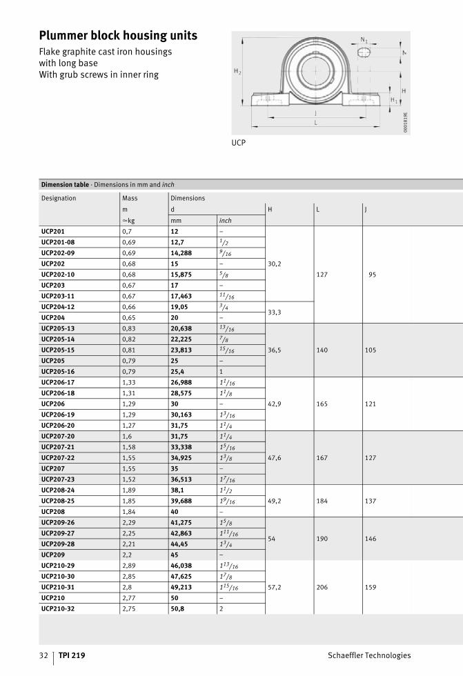
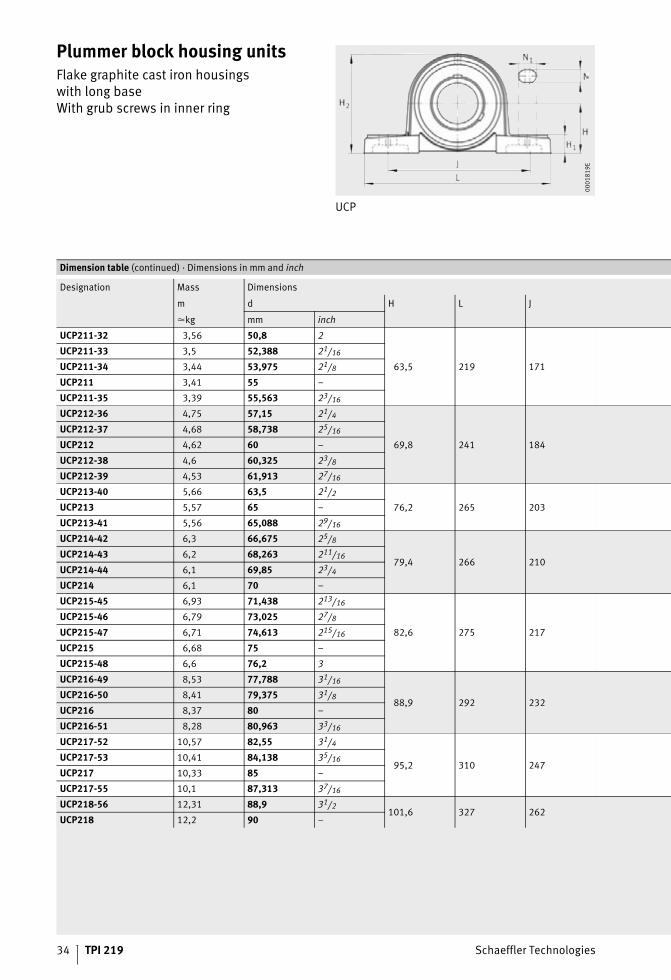
Plummer block housing unitsFlake graphite cast iron housingswith long baseWith grub screws in inner ring
UCP
00
01
81
9E
Dimension table · Dimensions in mm and inch
Designation Mass Dimensions
m d H L J
�kg mm inch
UCP201 0,7 12 –
30,2
127 95
UCP201-08 0,69 12,7 1/2
UCP202-09 0,69 14,288 9/16
UCP202 0,68 15 –
UCP202-10 0,68 15,875 5/8
UCP203 0,67 17 –
UCP203-11 0,67 17,463 11/16
UCP204-12 0,66 19,05 3/433,3
UCP204 0,65 20 –
UCP205-13 0,83 20,638 13/16
36,5 140 105
UCP205-14 0,82 22,225 7/8
UCP205-15 0,81 23,813 15/16
UCP205 0,79 25 –
UCP205-16 0,79 25,4 1
UCP206-17 1,33 26,988 11/16
42,9 165 121
UCP206-18 1,31 28,575 11/8
UCP206 1,29 30 –
UCP206-19 1,29 30,163 13/16
UCP206-20 1,27 31,75 11/4
UCP207-20 1,6 31,75 11/4
47,6 167 127
UCP207-21 1,58 33,338 15/16
UCP207-22 1,55 34,925 13/8
UCP207 1,55 35 –
UCP207-23 1,52 36,513 17/16
UCP208-24 1,89 38,1 11/2
49,2 184 137UCP208-25 1,85 39,688 19/16
UCP208 1,84 40 –
UCP209-26 2,29 41,275 15/8
54 190 146UCP209-27 2,25 42,863 111/16
UCP209-28 2,21 44,45 13/4
UCP209 2,2 45 –
UCP210-29 2,89 46,038 113/16
57,2 206 159
UCP210-30 2,85 47,625 17/8
UCP210-31 2,8 49,213 115/16
UCP210 2,77 50 –
UCP210-32 2,75 50,8 2
Schaeffler Technologies TPI 219 33
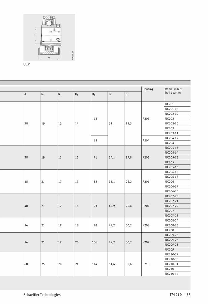
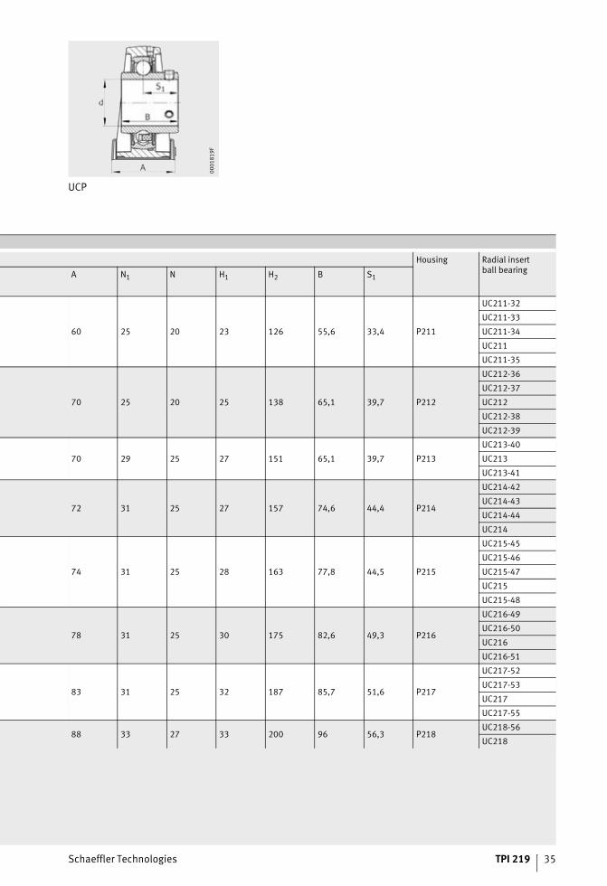
UCP
00
01
81
9F
Housing Radial insertball bearing
A N1 N H1 H2 B S1
38 19 13 14
62
31 18,3
P203
UC201
UC201-08
UC202-09
UC202
UC202-10
UC203
UC203-11
65 P204UC204-12
UC204
38 19 13 15 71 34,1 19,8 P205
UC205-13
UC205-14
UC205-15
UC205
UC205-16
48 21 17 17 83 38,1 22,2 P206
UC206-17
UC206-18
UC206
UC206-19
UC206-20
48 21 17 18 93 42,9 25,4 P207
UC207-20
UC207-21
UC207-22
UC207
UC207-23
54 21 17 18 98 49,2 30,2 P208
UC208-24
UC208-25
UC208
54 21 17 20 106 49,2 30,2 P209
UC209-26
UC209-27
UC209-28
UC209
60 25 20 21 114 51,6 32,6 P210
UC210-29
UC210-30
UC210-31
UC210
UC210-32
34 TPI 219 Schaeffler Technologies
Plummer block housing unitsFlake graphite cast iron housingswith long baseWith grub screws in inner ring
UCP
00
01
81
9E
Dimension table (continued) · Dimensions in mm and inch
Designation Mass Dimensions
m d H L J
�kg mm inch
UCP211-32 3,56 50,8 2
63,5 219 171
UCP211-33 3,5 52,388 21/16
UCP211-34 3,44 53,975 21/8
UCP211 3,41 55 –
UCP211-35 3,39 55,563 23/16
UCP212-36 4,75 57,15 21/4
69,8 241 184
UCP212-37 4,68 58,738 25/16
UCP212 4,62 60 –
UCP212-38 4,6 60,325 23/8
UCP212-39 4,53 61,913 27/16
UCP213-40 5,66 63,5 21/2
76,2 265 203UCP213 5,57 65 –
UCP213-41 5,56 65,088 29/16
UCP214-42 6,3 66,675 25/8
79,4 266 210UCP214-43 6,2 68,263 211/16
UCP214-44 6,1 69,85 23/4
UCP214 6,1 70 –
UCP215-45 6,93 71,438 213/16
82,6 275 217
UCP215-46 6,79 73,025 27/8
UCP215-47 6,71 74,613 215/16
UCP215 6,68 75 –
UCP215-48 6,6 76,2 3
UCP216-49 8,53 77,788 31/16
88,9 292 232UCP216-50 8,41 79,375 31/8
UCP216 8,37 80 –
UCP216-51 8,28 80,963 33/16
UCP217-52 10,57 82,55 31/4
95,2 310 247UCP217-53 10,41 84,138 35/16
UCP217 10,33 85 –
UCP217-55 10,1 87,313 37/16
UCP218-56 12,31 88,9 31/2101,6 327 262
UCP218 12,2 90 –
Schaeffler Technologies TPI 219 35
UCP
00
01
81
9F
Housing Radial insertball bearing
A N1 N H1 H2 B S1
60 25 20 23 126 55,6 33,4 P211
UC211-32
UC211-33
UC211-34
UC211
UC211-35
70 25 20 25 138 65,1 39,7 P212
UC212-36
UC212-37
UC212
UC212-38
UC212-39
70 29 25 27 151 65,1 39,7 P213
UC213-40
UC213
UC213-41
72 31 25 27 157 74,6 44,4 P214
UC214-42
UC214-43
UC214-44
UC214
74 31 25 28 163 77,8 44,5 P215
UC215-45
UC215-46
UC215-47
UC215
UC215-48
78 31 25 30 175 82,6 49,3 P216
UC216-49
UC216-50
UC216
UC216-51
83 31 25 32 187 85,7 51,6 P217
UC217-52
UC217-53
UC217
UC217-55
88 33 27 33 200 96 56,3 P218UC218-56
UC218
36 TPI 219 Schaeffler Technologies
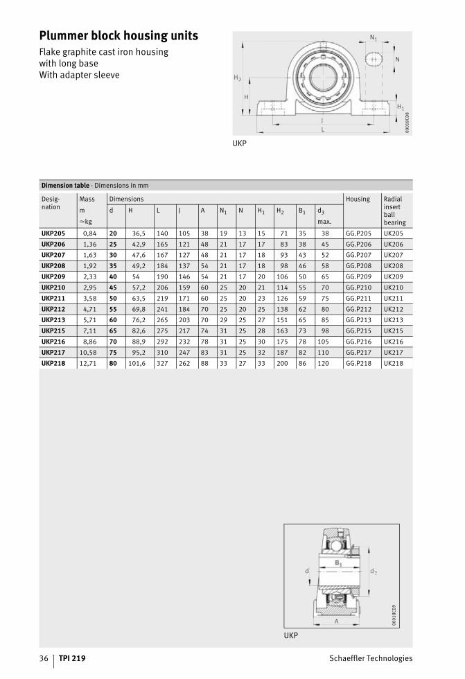
Plummer block housing unitsFlake graphite cast iron housingwith long baseWith adapter sleeve
UKP
00
01
8C
D8
Dimension table · Dimensions in mm
Desig-nation
Mass Dimensions Housing Radialinsertballbearing
m d H L J A N1 N H1 H2 B1 d3
�kg max.
UKP205 0,84 20 36,5 140 105 38 19 13 15 71 35 38 GG.P205 UK205
UKP206 1,36 25 42,9 165 121 48 21 17 17 83 38 45 GG.P206 UK206
UKP207 1,63 30 47,6 167 127 48 21 17 18 93 43 52 GG.P207 UK207
UKP208 1,92 35 49,2 184 137 54 21 17 18 98 46 58 GG.P208 UK208
UKP209 2,33 40 54 190 146 54 21 17 20 106 50 65 GG.P209 UK209
UKP210 2,95 45 57,2 206 159 60 25 20 21 114 55 70 GG.P210 UK210
UKP211 3,58 50 63,5 219 171 60 25 20 23 126 59 75 GG.P211 UK211
UKP212 4,71 55 69,8 241 184 70 25 20 25 138 62 80 GG.P212 UK212
UKP213 5,71 60 76,2 265 203 70 29 25 27 151 65 85 GG.P213 UK213
UKP215 7,11 65 82,6 275 217 74 31 25 28 163 73 98 GG.P215 UK215
UKP216 8,86 70 88,9 292 232 78 31 25 30 175 78 105 GG.P216 UK216
UKP217 10,58 75 95,2 310 247 83 31 25 32 187 82 110 GG.P217 UK217
UKP218 12,71 80 101,6 327 262 88 33 27 33 200 86 120 GG.P218 UK218
UKP
00
01
8C
D9

Schaeffler Technologies TPI 219 37
38 TPI 219 Schaeffler Technologies
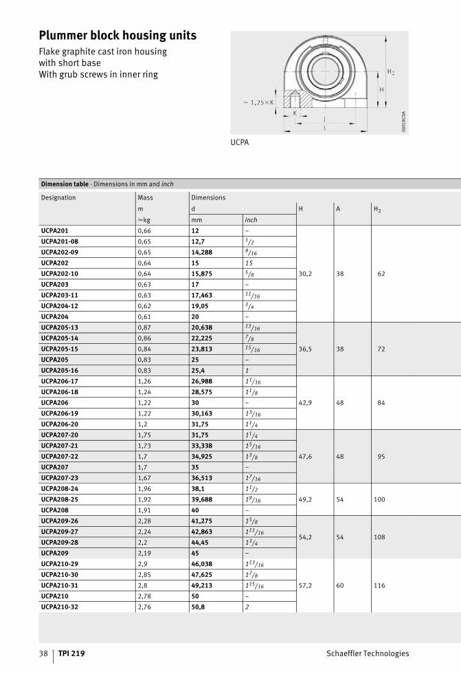
Plummer block housing unitsFlake graphite cast iron housingwith short baseWith grub screws in inner ring
UCPA
00
01
8C
DA
Dimension table · Dimensions in mm and inch
Designation Mass Dimensions
m d H A H2
�kg mm inch
UCPA201 0,66 12 –
30,2 38 62
UCPA201-08 0,65 12,7 1/2
UCPA202-09 0,65 14,288 9/16
UCPA202 0,64 15 15
UCPA202-10 0,64 15,875 5/8
UCPA203 0,63 17 –
UCPA203-11 0,63 17,463 11/16
UCPA204-12 0,62 19,05 3/4
UCPA204 0,61 20 –
UCPA205-13 0,87 20,638 13/16
36,5 38 72
UCPA205-14 0,86 22,225 7/8
UCPA205-15 0,84 23,813 15/16
UCPA205 0,83 25 –
UCPA205-16 0,83 25,4 1
UCPA206-17 1,26 26,988 11/16
42,9 48 84
UCPA206-18 1,24 28,575 11/8
UCPA206 1,22 30 –
UCPA206-19 1,22 30,163 13/16
UCPA206-20 1,2 31,75 11/4
UCPA207-20 1,75 31,75 11/4
47,6 48 95
UCPA207-21 1,73 33,338 15/16
UCPA207-22 1,7 34,925 13/8
UCPA207 1,7 35 –
UCPA207-23 1,67 36,513 17/16
UCPA208-24 1,96 38,1 11/2
49,2 54 100UCPA208-25 1,92 39,688 19/16
UCPA208 1,91 40 –
UCPA209-26 2,28 41,275 15/8
54,2 54 108UCPA209-27 2,24 42,863 111/16
UCPA209-28 2,2 44,45 13/4
UCPA209 2,19 45 –
UCPA210-29 2,9 46,038 113/16
57,2 60 116
UCPA210-30 2,85 47,625 17/8
UCPA210-31 2,8 49,213 115/16
UCPA210 2,78 50 –
UCPA210-32 2,76 50,8 2

Schaeffler Technologies TPI 219 39
UCPA
00
01
8C
DB
Housing Radial insertball bearing
K B J S1 L
M10 31 52 18,3 76 PA204
UC201
UC201-08
UC202-09
UC202
UC202-10
UC203
UC203-11
UC204-12
UC204
M10 34,1 56 19,8 84 PA205
UC205-13
UC205-14
UC205-15
UC205
UC205-16
M14 38,1 66 22,2 94 PA206
UC206-17
UC206-18
UC206
UC206-19
UC206-20
M14 42,9 80 25,4 110 PA207
UC207-20
UC207-21
UC207-22
UC207
UC207-23
M14 49,2 84 30,2 116 PA208
UC208-24
UC208-25
UC208
M14 49,2 90 30,2 120 PA209
UC209-26
UC209-27
UC209-28
UC209
M16 51,6 94 32,6 130 PA210
UC210-29
UC210-30
UC210-31
UC210
UC210-32

40 TPI 219 Schaeffler Technologies
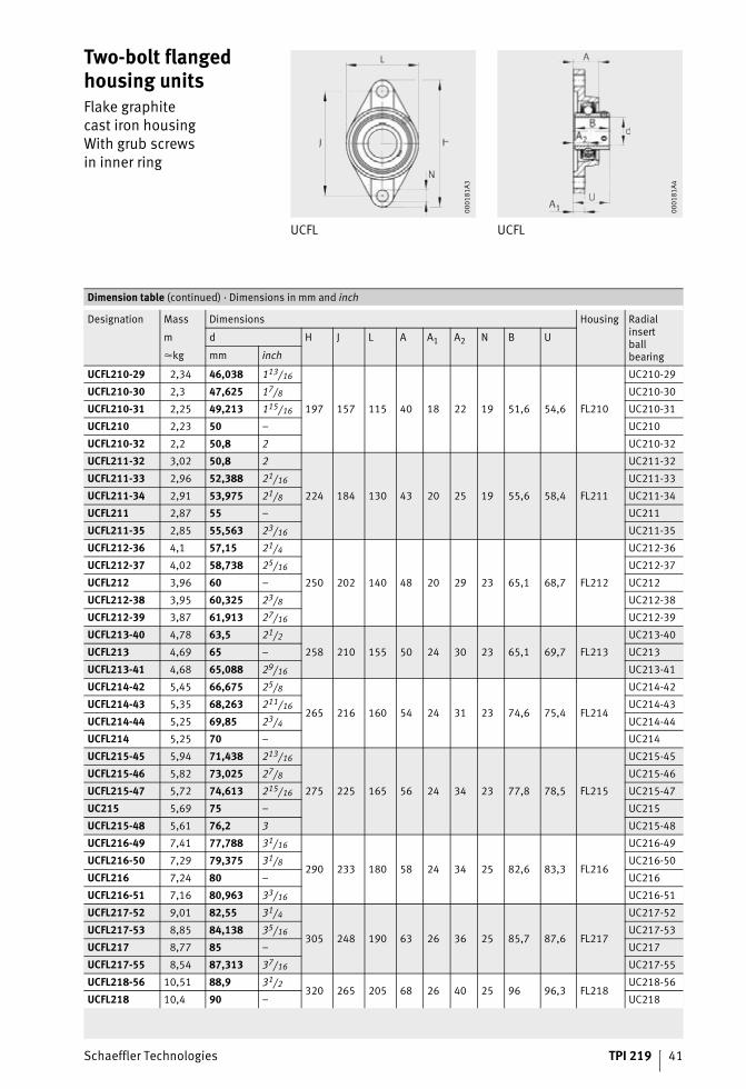
Two-bolt flanged housing unitsFlake graphitecast iron housingWith grub screwsin inner ring
UCFL UCFL
00
01
81
A3
00
01
81
A4
Dimension table · Dimensions in mm and inch
Designation Mass Dimensions Housing Radialinsertballbearing
m d H J L A A1 A2 N B U
�kg mm inch
UCFL201 0,47 12 –
113 90 60 25,5 12 15 12 31 33,3 FL204
UC201
UCFL201-08 0,47 12,7 1/2 UC201-08
UCFL202-09 0,46 14,288 9/16 UC202-09
UCFL202 0,46 15 – UC202
UCFL202-10 0,45 15,875 5/8 UC202-10
UCFL203 0,44 17 – UC203
UCFL203-11 0,44 17,463 11/16 UC203-11
UCFL204-12 0,43 19,05 3/4 UC204-12
UCFL204 0,42 20 – UC204
UCFL205-13 0,68 20,638 13/16
130 99 68 27 15 16 16 34,1 35,8 FL205
UC205-13
UCFL205-14 0,67 22,225 7/8 UC205-14
UCFL205-15 0,65 23,813 15/16 UC205-15
UCFL205 0,64 25 – UC205
UCFL205-16 0,64 25,4 1 UC205-16
UCFL206-17 0,92 26,988 11/16
148 117 80 31 14 18 16 38,1 40,2 FL206
UC206-17
UCFL206-18 0,9 28,575 11/8 UC206-18
UCFL206 0,88 30 – UC206
UCFL206-19 0,88 30,163 13/16 UC206-19
UCFL206-20 0,85 31,75 11/4 UC206-20
UCFL207-20 1,27 31,75 11/4
161 130 90 34 16 19 16 42,9 44,4 FL207
UC207-20
UCFL207-21 1,24 33,338 15/16 UC207-21
UCFL207-22 1,21 34,925 13/8 UC207-22
UCFL207 1,21 35 – UC207
UCFL207-23 1,18 36,513 17/16 UC207-23
UCFL208-24 1,53 38,1 11/2
175 144 100 36 16 21 16 49,2 51,2 FL208
UC208-24
UCFL208-25 1,49 39,688 19/16 UC208-25
UCFL208 1,48 40 – UC208
UCFL209-26 2,05 41,275 15/8
188 148 108 38 18 22 19 49,2 52,2 FL209
UC209-26
UCFL209-27 2,01 42,863 111/16 UC209-27
UCFL209-28 1,97 44,45 13/4 UC209-28
UCFL209 1,95 45 – UC209
Schaeffler Technologies TPI 219 41
Two-bolt flanged housing unitsFlake graphitecast iron housingWith grub screwsin inner ring
UCFL UCFL
00
01
81
A3
00
01
81
A4
Dimension table (continued) · Dimensions in mm and inch
Designation Mass Dimensions Housing Radialinsertballbearing
m d H J L A A1 A2 N B U
�kg mm inch
UCFL210-29 2,34 46,038 113/16
197 157 115 40 18 22 19 51,6 54,6 FL210
UC210-29
UCFL210-30 2,3 47,625 17/8 UC210-30
UCFL210-31 2,25 49,213 115/16 UC210-31
UCFL210 2,23 50 – UC210
UCFL210-32 2,2 50,8 2 UC210-32
UCFL211-32 3,02 50,8 2
224 184 130 43 20 25 19 55,6 58,4 FL211
UC211-32
UCFL211-33 2,96 52,388 21/16 UC211-33
UCFL211-34 2,91 53,975 21/8 UC211-34
UCFL211 2,87 55 – UC211
UCFL211-35 2,85 55,563 23/16 UC211-35
UCFL212-36 4,1 57,15 21/4
250 202 140 48 20 29 23 65,1 68,7 FL212
UC212-36
UCFL212-37 4,02 58,738 25/16 UC212-37
UCFL212 3,96 60 – UC212
UCFL212-38 3,95 60,325 23/8 UC212-38
UCFL212-39 3,87 61,913 27/16 UC212-39
UCFL213-40 4,78 63,5 21/2
258 210 155 50 24 30 23 65,1 69,7 FL213
UC213-40
UCFL213 4,69 65 – UC213
UCFL213-41 4,68 65,088 29/16 UC213-41
UCFL214-42 5,45 66,675 25/8
265 216 160 54 24 31 23 74,6 75,4 FL214
UC214-42
UCFL214-43 5,35 68,263 211/16 UC214-43
UCFL214-44 5,25 69,85 23/4 UC214-44
UCFL214 5,25 70 – UC214
UCFL215-45 5,94 71,438 213/16
275 225 165 56 24 34 23 77,8 78,5 FL215
UC215-45
UCFL215-46 5,82 73,025 27/8 UC215-46
UCFL215-47 5,72 74,613 215/16 UC215-47
UC215 5,69 75 – UC215
UCFL215-48 5,61 76,2 3 UC215-48
UCFL216-49 7,41 77,788 31/16
290 233 180 58 24 34 25 82,6 83,3 FL216
UC216-49
UCFL216-50 7,29 79,375 31/8 UC216-50
UCFL216 7,24 80 – UC216
UCFL216-51 7,16 80,963 33/16 UC216-51
UCFL217-52 9,01 82,55 31/4
305 248 190 63 26 36 25 85,7 87,6 FL217
UC217-52
UCFL217-53 8,85 84,138 35/16 UC217-53
UCFL217 8,77 85 – UC217
UCFL217-55 8,54 87,313 37/16 UC217-55
UCFL218-56 10,51 88,9 31/2320 265 205 68 26 40 25 96 96,3 FL218
UC218-56
UCFL218 10,4 90 – UC218
42 TPI 219 Schaeffler Technologies
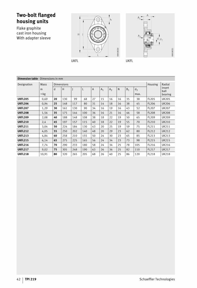
Two-bolt flanged housing unitsFlake graphitecast iron housingWith adapter sleeve
UKFL UKFL
00
01
8C
E0
00
01
8C
E1
Dimension table · Dimensions in mm
Designation Mass Dimensions Housing Radialinsertballbearing
m d H J L A A1 A2 N B1 d3
�kg max.
UKFL205 0,69 20 130 99 68 27 15 16 16 35 38 FL205 UK205
UKFL206 0,94 25 148 117 80 31 14 18 16 38 45 FL206 UK206
UKFL207 1,29 30 161 130 90 34 16 19 16 43 52 FL207 UK207
UKFL208 1,56 35 175 144 100 36 16 21 16 46 58 FL208 UK208
UKFL209 2,08 40 188 148 108 38 18 22 19 50 65 FL209 UK209
UKFL210 2,4 45 197 157 115 40 18 22 19 55 70 FL210 UK210
UKFL211 3,04 50 224 184 130 43 20 25 19 59 75 FL211 UK211
UKFL212 4,05 55 250 202 140 48 20 29 23 62 80 FL212 UK212
UKFL213 4,84 60 258 210 155 50 24 30 23 65 85 FL213 UK213
UKFL215 6,14 65 275 225 165 56 24 34 23 73 98 FL215 UK215
UKFL216 7,74 70 290 233 180 58 24 34 25 78 105 FL216 UK216
UKFL217 9,02 75 305 248 190 63 26 36 25 82 110 FL217 UK217
UKFL218 10,91 80 320 265 205 68 26 40 25 86 120 FL218 UK218

Schaeffler Technologies TPI 219 43
44 TPI 219 Schaeffler Technologies
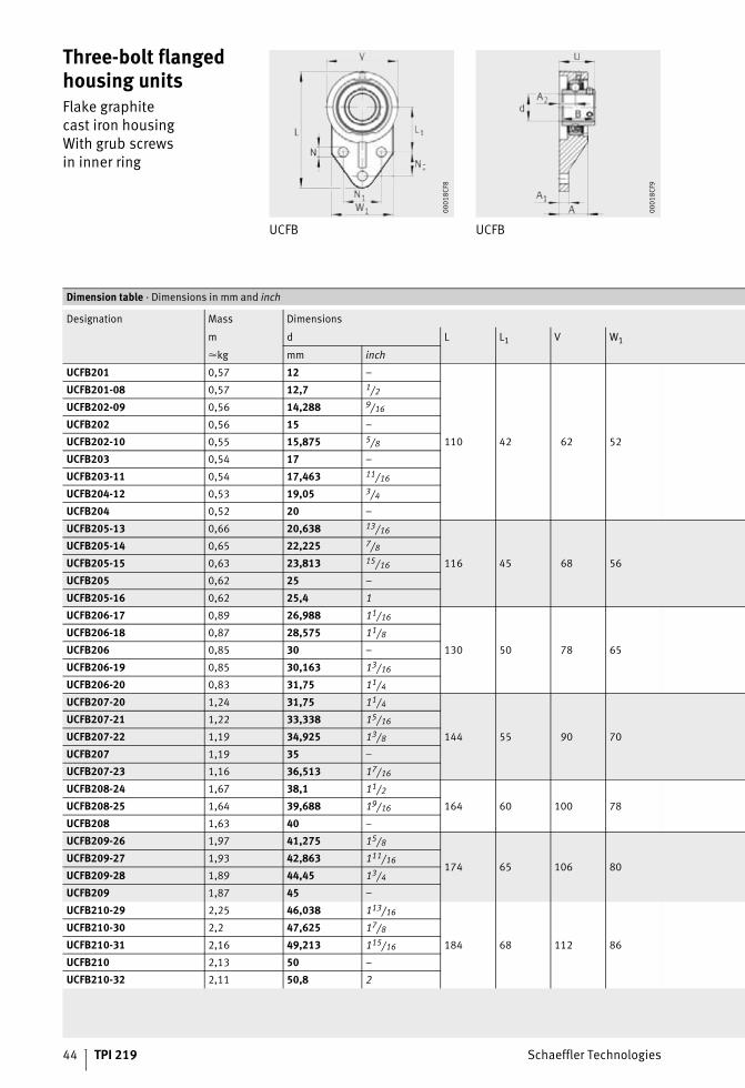
Three-bolt flanged housing unitsFlake graphitecast iron housingWith grub screwsin inner ring
UCFB UCFB
00
01
8C
F8
00
01
8C
F9
Dimension table · Dimensions in mm and inch
Designation Mass Dimensions
m d L L1 V W1
�kg mm inch
UCFB201 0,57 12 –
110 42 62 52
UCFB201-08 0,57 12,7 1/2
UCFB202-09 0,56 14,288 9/16
UCFB202 0,56 15 –
UCFB202-10 0,55 15,875 5/8
UCFB203 0,54 17 –
UCFB203-11 0,54 17,463 11/16
UCFB204-12 0,53 19,05 3/4
UCFB204 0,52 20 –
UCFB205-13 0,66 20,638 13/16
116 45 68 56
UCFB205-14 0,65 22,225 7/8
UCFB205-15 0,63 23,813 15/16
UCFB205 0,62 25 –
UCFB205-16 0,62 25,4 1
UCFB206-17 0,89 26,988 11/16
130 50 78 65
UCFB206-18 0,87 28,575 11/8
UCFB206 0,85 30 –
UCFB206-19 0,85 30,163 13/16
UCFB206-20 0,83 31,75 11/4
UCFB207-20 1,24 31,75 11/4
144 55 90 70
UCFB207-21 1,22 33,338 15/16
UCFB207-22 1,19 34,925 13/8
UCFB207 1,19 35 –
UCFB207-23 1,16 36,513 17/16
UCFB208-24 1,67 38,1 11/2
164 60 100 78UCFB208-25 1,64 39,688 19/16
UCFB208 1,63 40 –
UCFB209-26 1,97 41,275 15/8
174 65 106 80UCFB209-27 1,93 42,863 111/16
UCFB209-28 1,89 44,45 13/4
UCFB209 1,87 45 –
UCFB210-29 2,25 46,038 113/16
184 68 112 86
UCFB210-30 2,2 47,625 17/8
UCFB210-31 2,16 49,213 115/16
UCFB210 2,13 50 –
UCFB210-32 2,11 50,8 2

Schaeffler Technologies TPI 219 45
Housing Radial insertball bearing
A A1 A2 N N1 N2 B U
24 13 13,5 9,5 32 27 31 31,8 FB204
UC201
UC201-08
UC202-09
UC202
UC202-10
UC203
UC203-11
UC204-12
UC204
26 13 15 9,5 34 27 34,1 34,8 FB205
UC205-13
UC205-14
UC205-15
UC205
UC205-16
29 13 17 9,5 40 29 38,1 39,2 FB206
UC206-17
UC206-18
UC206
UC206-19
UC206-20
33 15 19 9,5 46 32 42,9 44,4 FB207
UC207-20
UC207-21
UC207-22
UC207
UC207-23
34 16 20 11,1 50 41 49,2 50,2 FB208
UC208-24
UC208-25
UC208
34 18 20 11,1 54 43 49,2 50,2 FB209
UC209-26
UC209-27
UC209-28
UC209
35 18 20 11,1 58 46 51,6 52,6 FB210
UC210-29
UC210-30
UC210-31
UC210
UC210-32
46 TPI 219 Schaeffler Technologies
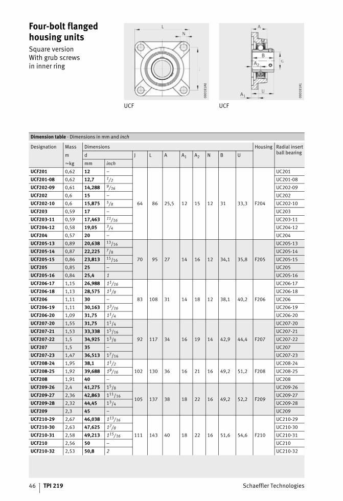
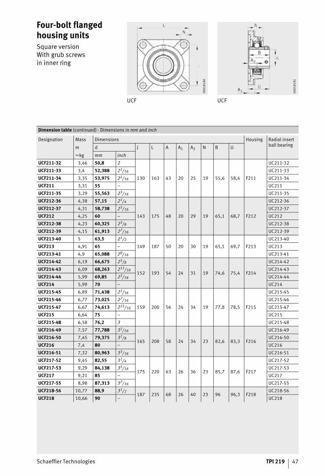
Four-bolt flanged housing unitsSquare versionWith grub screwsin inner ring
UCF UCF
00
01
81
A0
00
01
81
A1
Dimension table · Dimensions in mm and inch
Designation Mass Dimensions Housing Radial insertball bearing
m d J L A A1 A2 N B U
�kg mm inch
UCF201 0,62 12 –
64 86 25,5 12 15 12 31 33,3 F204
UC201
UCF201-08 0,62 12,7 1/2 UC201-08
UCF202-09 0,61 14,288 9/16 UC202-09
UCF202 0,6 15 – UC202
UCF202-10 0,6 15,875 5/8 UC202-10
UCF203 0,59 17 – UC203
UCF203-11 0,59 17,463 11/16 UC203-11
UCF204-12 0,58 19,05 3/4 UC204-12
UCF204 0,57 20 – UC204
UCF205-13 0,89 20,638 13/16
70 95 27 14 16 12 34,1 35,8 F205
UC205-13
UCF205-14 0,87 22,225 7/8 UC205-14
UCF205-15 0,86 23,813 15/16 UC205-15
UCF205 0,85 25 – UC205
UCF205-16 0,84 25,4 1 UC205-16
UCF206-17 1,15 26,988 11/16
83 108 31 14 18 12 38,1 40,2 F206
UC206-17
UCF206-18 1,13 28,575 11/8 UC206-18
UCF206 1,11 30 – UC206
UCF206-19 1,11 30,163 13/16 UC206-19
UCF206-20 1,09 31,75 11/4 UC206-20
UCF207-20 1,55 31,75 11/4
92 117 34 16 19 14 42,9 44,4 F207
UC207-20
UCF207-21 1,53 33,338 15/16 UC207-21
UCF207-22 1,5 34,925 13/8 UC207-22
UCF207 1,5 35 – UC207
UCF207-23 1,47 36,513 17/16 UC207-23
UCF208-24 1,95 38,1 11/2
102 130 36 16 21 16 49,2 51,2 F208
UC208-24
UCF208-25 1,92 39,688 19/16 UC208-25
UCF208 1,91 40 – UC208
UCF209-26 2,4 41,275 15/8
105 137 38 18 22 16 49,2 52,2 F209
UC209-26
UCF209-27 2,36 42,863 111/16 UC209-27
UCF209-28 2,32 44,45 13/4 UC209-28
UCF209 2,3 45 – UC209
UCF210-29 2,67 46,038 113/16
111 143 40 18 22 16 51,6 54,6 F210
UC210-29
UCF210-30 2,63 47,625 17/8 UC210-30
UCF210-31 2,58 49,213 115/16 UC210-31
UCF210 2,56 50 – UC210
UCF210-32 2,53 50,8 2 UC210-32
Schaeffler Technologies TPI 219 47
Four-bolt flanged housing unitsSquare versionWith grub screwsin inner ring
UCF UCF
00
01
81
A0
00
01
81
A1
Dimension table (continued) · Dimensions in mm and inch
Designation Mass Dimensions Housing Radial insertball bearing
m d J L A A1 A2 N B U
�kg mm inch
UCF211-32 3,46 50,8 2
130 163 43 20 25 19 55,6 58,4 F211
UC211-32
UCF211-33 3,4 52,388 21/16 UC211-33
UCF211-34 3,35 53,975 21/16 UC211-34
UCF211 3,31 55 – UC211
UCF211-35 3,29 55,563 23/16 UC211-35
UCF212-36 4,38 57,15 21/4
143 175 48 20 29 19 65,1 68,7 F212
UC212-36
UCF212-37 4,31 58,738 25/16 UC212-37
UCF212 4,25 60 – UC212
UCF212-38 4,23 60,325 23/8 UC212-38
UCF212-39 4,15 61,913 27/16 UC212-39
UCF213-40 5 63,5 21/2
149 187 50 20 30 19 65,1 69,7 F213
UC213-40
UCF213 4,91 65 – UC213
UCF213-41 4,9 65,088 29/16 UC213-41
UCF214-42 6,19 66,675 25/8
152 193 54 24 31 19 74,6 75,4 F214
UC214-42
UCF214-43 6,09 68,263 211/16 UC214-43
UCF214-44 5,99 69,85 23/16 UC214-44
UCF214 5,99 70 – UC214
UCF215-45 6,89 71,438 21/16
159 200 56 24 34 19 77,8 78,5 F215
UC215-45
UCF215-46 6,77 73,025 27/16 UC215-46
UCF215-47 6,67 74,613 215/16 UC215-47
UCF215 6,64 75 – UC215
UCF215-48 6,58 76,2 3 UC215-48
UCF216-49 7,57 77,788 31/16
165 208 58 24 34 23 82,6 83,3 F216
UC216-49
UCF216-50 7,45 79,375 31/8 UC216-50
UCF216 7,4 80 – UC216
UCF216-51 7,32 80,963 33/16 UC216-51
UCF217-52 9,45 82,55 31/4
175 220 63 26 36 23 85,7 87,6 F217
UC217-52
UCF217-53 9,29 84,138 35/16 UC217-53
UCF217 9,21 85 – UC217
UCF217-55 8,98 87,313 37/16 UC217-55
UCF218-56 10,77 88,9 31/2187 235 68 26 40 23 96 96,3 F218
UC218-56
UCF218 10,66 90 – UC218
48 TPI 219 Schaeffler Technologies
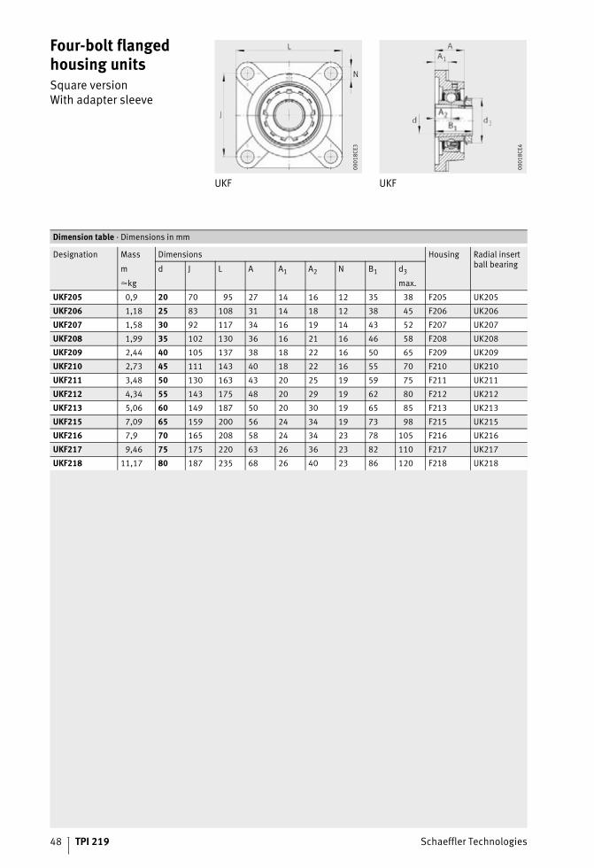
Four-bolt flanged housing unitsSquare versionWith adapter sleeve
UKF UKF
00
01
8C
E3
00
01
8C
E4
Dimension table · Dimensions in mm
Designation Mass Dimensions Housing Radial insertball bearing
m d J L A A1 A2 N B1 d3
�kg max.
UKF205 0,9 20 70 95 27 14 16 12 35 38 F205 UK205
UKF206 1,18 25 83 108 31 14 18 12 38 45 F206 UK206
UKF207 1,58 30 92 117 34 16 19 14 43 52 F207 UK207
UKF208 1,99 35 102 130 36 16 21 16 46 58 F208 UK208
UKF209 2,44 40 105 137 38 18 22 16 50 65 F209 UK209
UKF210 2,73 45 111 143 40 18 22 16 55 70 F210 UK210
UKF211 3,48 50 130 163 43 20 25 19 59 75 F211 UK211
UKF212 4,34 55 143 175 48 20 29 19 62 80 F212 UK212
UKF213 5,06 60 149 187 50 20 30 19 65 85 F213 UK213
UKF215 7,09 65 159 200 56 24 34 19 73 98 F215 UK215
UKF216 7,9 70 165 208 58 24 34 23 78 105 F216 UK216
UKF217 9,46 75 175 220 63 26 36 23 82 110 F217 UK217
UKF218 11,17 80 187 235 68 26 40 23 86 120 F218 UK218

Schaeffler Technologies TPI 219 49
50 TPI 219 Schaeffler Technologies
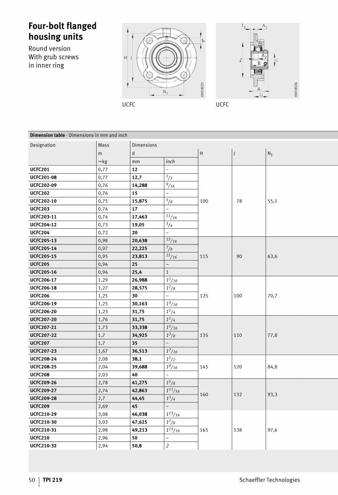
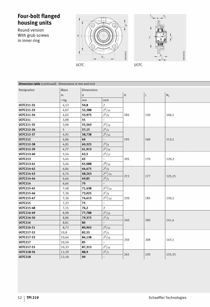
Four-bolt flanged housing unitsRound versionWith grub screwsin inner ring
UCFC UCFC
00
01
8C
E5
00
01
8C
E6
Dimension table · Dimensions in mm and inch
Designation Mass Dimensions
m d H J N1
�kg mm inch
UCFC201 0,77 12 –
100 78 55,1
UCFC201-08 0,77 12,7 1/2
UCFC202-09 0,76 14,288 9/16
UCFC202 0,76 15 –
UCFC202-10 0,75 15,875 5/8
UCFC203 0,74 17 –
UCFC203-11 0,74 17,463 11/16
UCFC204-12 0,73 19,05 3/4
UCFC204 0,72 20 –
UCFC205-13 0,98 20,638 13/16
115 90 63,6
UCFC205-14 0,97 22,225 7/8
UCFC205-15 0,95 23,813 15/16
UCFC205 0,94 25 –
UCFC205-16 0,94 25,4 1
UCFC206-17 1,29 26,988 11/16
125 100 70,7
UCFC206-18 1,27 28,575 11/8
UCFC206 1,25 30 –
UCFC206-19 1,25 30,163 13/16
UCFC206-20 1,23 31,75 11/4
UCFC207-20 1,76 31,75 11/4
135 110 77,8
UCFC207-21 1,73 33,338 15/16
UCFC207-22 1,7 34,925 13/8
UCFC207 1,7 35 –
UCFC207-23 1,67 36,513 17/16
UCFC208-24 2,08 38,1 11/2
145 120 84,8UCFC208-25 2,04 39,688 19/16
UCFC208 2,03 40 –
UCFC209-26 2,78 41,275 15/8
160 132 93,3UCFC209-27 2,74 42,863 111/16
UCFC209-28 2,7 44,45 13/4
UCFC209 2,69 45 –
UCFC210-29 3,08 46,038 113/16
165 138 97,6
UCFC210-30 3,03 47,625 17/8
UCFC210-31 2,98 49,213 115/16
UCFC210 2,96 50 –
UCFC210-32 2,94 50,8 2
Schaeffler Technologies TPI 219 51
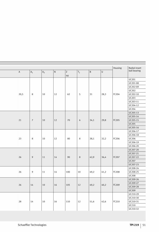
Housing Radial insertball bearing
A A1 A2 N Z T1 B U
h8
20,5 8 10 12 62 5 31 28,3 FC204
UC201
UC201-08
UC202-09
UC202
UC202-10
UC203
UC203-11
UC204-12
UC204
21 7 10 12 70 6 34,1 29,8 FC205
UC205-13
UC205-14
UC205-15
UC205
UC205-16
23 8 10 12 80 8 38,1 32,2 FC206
UC206-17
UC206-18
UC206
UC206-19
UC206-20
26 9 11 14 90 8 42,9 36,4 FC207
UC207-20
UC207-21
UC207-22
UC207
UC207-23
26 9 11 14 100 10 49,2 41,2 FC208
UC208-24
UC208-25
UC208
26 14 10 16 105 12 49,2 40,2 FC209
UC209-26
UC209-27
UC209-28
UC209
28 14 10 16 110 12 51,6 42,6 FC210
UC210-29
UC210-30
UC210-31
UC210
UC210-32
52 TPI 219 Schaeffler Technologies
Four-bolt flanged housing unitsRound versionWith grub screwsin inner ring
UCFC UCFC
00
01
8C
E5
00
01
8C
E6
Dimension table (continued) · Dimensions in mm and inch
Designation Mass Dimensions
m d H J N1
�kg mm inch
UCFC211-32 4,13 50,8 2
185 150 106,1
UCFC211-33 4,07 52,388 21/16
UCFC211-34 4,02 53,975 21/8
UCFC211 3,98 55 –
UCFC211-35 3,96 55,563 23/16
UCFC212-36 5 57,15 21/4
195 160 113,1
UCFC212-37 4,92 58,738 25/16
UCFC212 4,86 60 –
UCFC212-38 4,85 60,325 23/8
UCFC212-39 4,77 61,913 27/16
UCFC213-40 5,54 63,5 21/12
205 170 120,2UCFC213 5,45 65 –
UCFC213-41 5,44 65,088 29/16
UCFC214-42 6,84 66,675 25/8
215 177 125,15UCFC214-43 6,74 68,263 211/16
UCFC214-44 6,64 69,85 23/4
UCFC214 6,64 70 –
UCFC215-45 7,48 71,438 213/16
220 184 130,1
UCFC215-46 7,36 73,025 27/8
UCFC215-47 7,26 74,613 215/16
UCFC215 7,23 75 –
UCFC215-48 7,15 76,2 3
UCFC216-49 8,98 77,788 21/16
240 200 141,4UCFC216-50 8,86 79,375 21/8
UCFC216 8,81 80 –
UCFC216-51 8,73 80,963 23/16
UCFC217-52 10,8 82,55 21/4
250 208 147,1UCFC217-53 10,64 84,138 25/16
UCFC217 10,56 85 –
UCFC217-55 10,33 87,313 27/16
UCFC218-56 12,29 88,9 21/2265 220 155,55
UCFC218 12,18 90 –
Schaeffler Technologies TPI 219 53
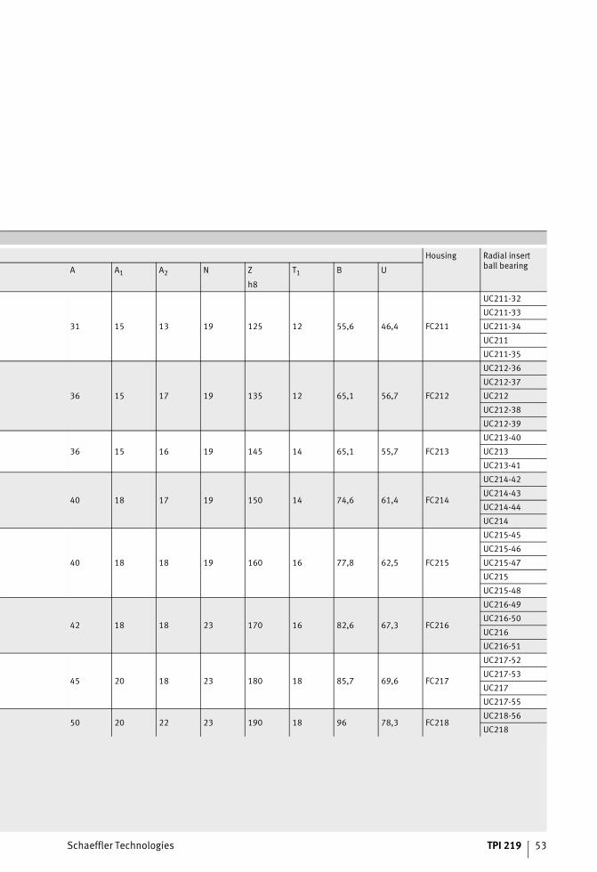
Housing Radial insertball bearing
A A1 A2 N Z T1 B U
h8
31 15 13 19 125 12 55,6 46,4 FC211
UC211-32
UC211-33
UC211-34
UC211
UC211-35
36 15 17 19 135 12 65,1 56,7 FC212
UC212-36
UC212-37
UC212
UC212-38
UC212-39
36 15 16 19 145 14 65,1 55,7 FC213
UC213-40
UC213
UC213-41
40 18 17 19 150 14 74,6 61,4 FC214
UC214-42
UC214-43
UC214-44
UC214
40 18 18 19 160 16 77,8 62,5 FC215
UC215-45
UC215-46
UC215-47
UC215
UC215-48
42 18 18 23 170 16 82,6 67,3 FC216
UC216-49
UC216-50
UC216
UC216-51
45 20 18 23 180 18 85,7 69,6 FC217
UC217-52
UC217-53
UC217
UC217-55
50 20 22 23 190 18 96 78,3 FC218UC218-56
UC218
54 TPI 219 Schaeffler Technologies
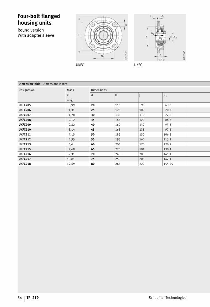
Four-bolt flanged housing unitsRound versionWith adapter sleeve
UKFC UKFC
00
01
8C
E9
00
01
8C
EA
Dimension table · Dimensions in mm
Designation Mass Dimensions
m d H J N1
�kg
UKFC205 0,99 20 115 90 63,6
UKFC206 1,31 25 125 100 70,7
UKFC207 1,78 30 135 110 77,8
UKFC208 2,12 35 145 120 84,8
UKFC209 2,82 40 160 132 93,3
UKFC210 3,14 45 165 138 97,6
UKFC211 4,15 50 185 150 106,1
UKFC212 4,95 55 195 160 113,1
UKFC213 5,6 60 205 170 120,2
UKFC215 7,68 65 220 184 130,1
UKFC216 9,31 70 240 200 141,4
UKFC217 10,81 75 250 208 147,1
UKFC218 12,69 80 265 220 155,55
Schaeffler Technologies TPI 219 55
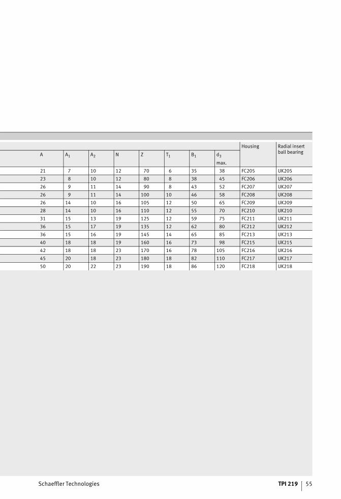
Housing Radial insertball bearing
A A1 A2 N Z T1 B1 d3
max.
21 7 10 12 70 6 35 38 FC205 UK205
23 8 10 12 80 8 38 45 FC206 UK206
26 9 11 14 90 8 43 52 FC207 UK207
26 9 11 14 100 10 46 58 FC208 UK208
26 14 10 16 105 12 50 65 FC209 UK209
28 14 10 16 110 12 55 70 FC210 UK210
31 15 13 19 125 12 59 75 FC211 UK211
36 15 17 19 135 12 62 80 FC212 UK212
36 15 16 19 145 14 65 85 FC213 UK213
40 18 18 19 160 16 73 98 FC215 UK215
42 18 18 23 170 16 78 105 FC216 UK216
45 20 18 23 180 18 82 110 FC217 UK217
50 20 22 23 190 18 86 120 FC218 UK218

56 TPI 219 Schaeffler Technologies
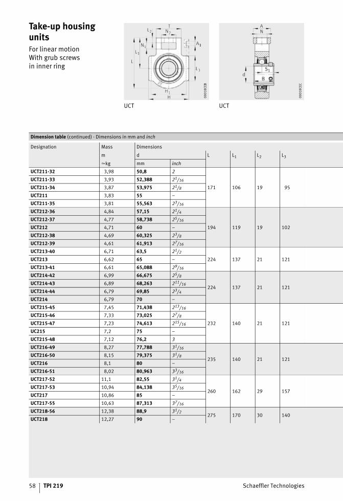
Take-up housing unitsFor linear motionWith grub screwsin inner ring
UCT UCT
00
01
8C
EB
00
01
8C
EC
Dimension table · Dimensions in mm and inch
Designation Mass Dimensions
m d L L1 L2 L3
�kg mm inch
UCT201 0,77 12 –
94 61 10 51
UCT201-08 0,77 12,7 1/2
UCT202-09 0,76 14,288 9/16
UCT202 0,75 15 –
UCT202-10 0,75 15,875 5/8
UCT203 0,74 17 –
UCT203-11 0,74 17,463 11/16
UCT204-12 0,73 19,05 3/4
UCT204 0,72 20 –
UCT205-13 0,84 20,638 13/16
97 62 10 51
UCT205-14 0,83 22,225 7/8
UCT205-15 0,81 23,813 15/16
UCT205 0,8 25 –
UCT205-16 0,8 25,4 1
UCT206-17 1,27 26,988 11/16
113 70 10 57
UCT206-18 1,25 28,575 11/8
UCT206 1,23 30 –
UCT206-19 1,23 30,163 13/16
UCT206-20 1,2 31,75 11/4
UCT207-20 1,64 31,75 11/4
129 78 13 64
UCT207-21 1,61 33,338 15/16
UCT207-22 1,58 34,925 13/8
UCT207 1,58 35 –
UCT207-23 1,55 36,513 17/16
UCT208-24 2,36 38,1 11/2
144 88 16 83UCT208-25 2,33 39,688 19/16
UCT208 2,32 40 –
UCT209-26 2,46 41,275 15/8
144 87 16 83UCT209-27 2,42 42,863 111/16
UCT209-28 2,38 44,45 13/4
UCT209 2,37 45 –
UCT210-29 2,64 46,038 113/16
149 90 16 86
UCT210-30 2,59 47,625 17/8
UCT210-31 2,54 49,213 115/16
UCT210 2,52 50 –
UCT210-32 2,5 50,8 2

Schaeffler Technologies TPI 219 57
Housing Radial insertball bearing
N N1 N2 A H H1 A1 B S1 T
19 16 32 32 89 76 12 31 18,3 51 T204
UC201
UC201-08
UC202-09
UC202
UC202-10
UC203
UC203-11
UC204-12
UC204
19 16 32 32 89 76 12 34,1 19,8 51 T205
UC205-13
UC205-14
UC205-15
UC205
UC205-16
22 16 37 37 102 89 12 38,1 22,2 56 T206
UC206-17
UC206-18
UC206
UC206-19
UC206-20
22 16 37 37 102 89 12 42,9 25,4 64 T207
UC207-20
UC207-21
UC207-22
UC207
UC207-23
29 19 49 49 114 102 16 49,2 30,2 83 T208
UC208-24
UC208-25
UC208
29 19 49 49 117 102 16 49,2 30,2 83 T209
UC209-26
UC209-27
UC209-28
UC209
29 19 49 49 117 102 16 51,6 32,6 83 T210
UC210-29
UC210-30
UC210-31
UC210
UC210-32
58 TPI 219 Schaeffler Technologies
Take-up housing unitsFor linear motionWith grub screwsin inner ring
UCT UCT
00
01
8C
EB
00
01
8C
EC
Dimension table (continued) · Dimensions in mm and inch
Designation Mass Dimensions
m d L L1 L2 L3
�kg mm inch
UCT211-32 3,98 50,8 2
171 106 19 95
UCT211-33 3,93 52,388 21/16
UCT211-34 3,87 53,975 21/8
UCT211 3,83 55 –
UCT211-35 3,81 55,563 23/16
UCT212-36 4,84 57,15 21/4
194 119 19 102
UCT212-37 4,77 58,738 25/16
UCT212 4,71 60 –
UCT212-38 4,69 60,325 23/8
UCT212-39 4,61 61,913 27/16
UCT213-40 6,71 63,5 21/2
224 137 21 121UCT213 6,62 65 –
UCT213-41 6,61 65,088 29/16
UCT214-42 6,99 66,675 25/8
224 137 21 121UCT214-43 6,89 68,263 211/16
UCT214-44 6,79 69,85 23/4
UCT214 6,79 70 –
UCT215-45 7,45 71,438 213/16
232 140 21 121
UCT215-46 7,33 73,025 27/8
UCT215-47 7,23 74,613 215/16
UC215 7,2 75 –
UCT215-48 7,12 76,2 3
UCT216-49 8,27 77,788 31/16
235 140 21 121UCT216-50 8,15 79,375 31/8
UCT216 8,1 80 –
UCT216-51 8,02 80,963 33/16
UCT217-52 11,1 82,55 31/4
260 162 29 157UCT217-53 10,94 84,138 35/16
UCT217 10,86 85 –
UCT217-55 10,63 87,313 37/16
UCT218-56 12,38 88,9 31/2275 170 30 140
UCT218 12,27 90 –

Schaeffler Technologies TPI 219 59
Housing Radial insertball bearing
N N1 N2 A H H1 A1 B S1 T
35 25 64 64 146 130 22 55,6 33,4 102 T211
UC211-32
UC211-33
UC211-34
UC211
UC211-35
35 32 64 64 146 130 22 65,1 39,7 102 T212
UC212-36
UC212-37
UC212
UC212-38
UC212-39
41 32 70 70 167 151 26 65,1 39,7 111 T213
UC213-40
UC213
UC213-41
41 32 70 70 167 151 26 74,6 44,4 111 T214
UC214-42
UC214-43
UC214-44
UC214
41 32 70 70 167 151 26 77,8 44,5 111 T215
UC215-45
UC215-46
UC215-47
UC215
UC215-48
41 32 70 70 184 165 26 82,6 49,3 111 T216
UC216-49
UC216-50
UC216
UC216-51
48 38 73 73 198 173 30 85,7 51,6 124 T217
UC217-52
UC217-53
UC217
UC217-55
47 40 80 80 215 190 28 96 56,3 130 T218UC218-56
UC218
60 TPI 219 Schaeffler Technologies
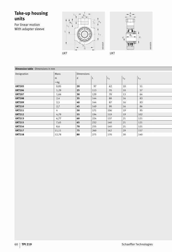
Take-up housing unitsFor linear motionWith adapter sleeve
UKT UKT
00
01
8C
EF
00
01
8C
F0
Dimension table · Dimensions in mm
Designation Mass Dimensions
m d L L1 L2 L3
�kg
UKT205 0,85 20 97 62 10 51
UKT206 1,29 25 113 70 10 57
UKT207 1,66 30 129 78 13 64
UKT208 2,4 35 144 88 16 83
UKT209 2,5 40 144 87 16 83
UKT210 2,7 45 149 90 16 86
UKT211 4 50 171 106 19 95
UKT212 4,79 55 194 119 19 102
UKT213 6,77 60 224 137 21 121
UKT215 7,65 65 232 140 21 121
UKT216 8,6 70 235 140 21 121
UKT217 11,11 75 260 162 29 157
UKT218 12,78 80 275 170 30 140
Schaeffler Technologies TPI 219 61
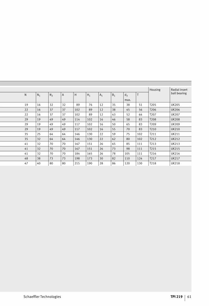
Housing Radial insertball bearing
N N1 N2 A H H1 A1 B1 d3 T
max.
19 16 32 32 89 76 12 35 38 51 T205 UK205
22 16 37 37 102 89 12 38 45 56 T206 UK206
22 16 37 37 102 89 12 43 52 64 T207 UK207
29 19 49 49 114 102 16 46 58 83 T208 UK208
29 19 49 49 117 102 16 50 65 83 T209 UK209
29 19 49 49 117 102 16 55 70 83 T210 UK210
35 25 64 64 146 130 22 59 75 102 T211 UK211
35 32 64 64 146 130 22 62 80 102 T212 UK212
41 32 70 70 167 151 26 65 85 111 T213 UK213
41 32 70 70 167 151 26 73 98 111 T215 UK215
41 32 70 70 184 165 26 78 105 111 T216 UK216
48 38 73 73 198 173 30 82 110 124 T217 UK217
47 40 80 80 215 190 28 86 120 130 T218 UK218
62 TPI 219 Schaeffler Technologies
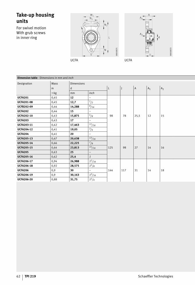
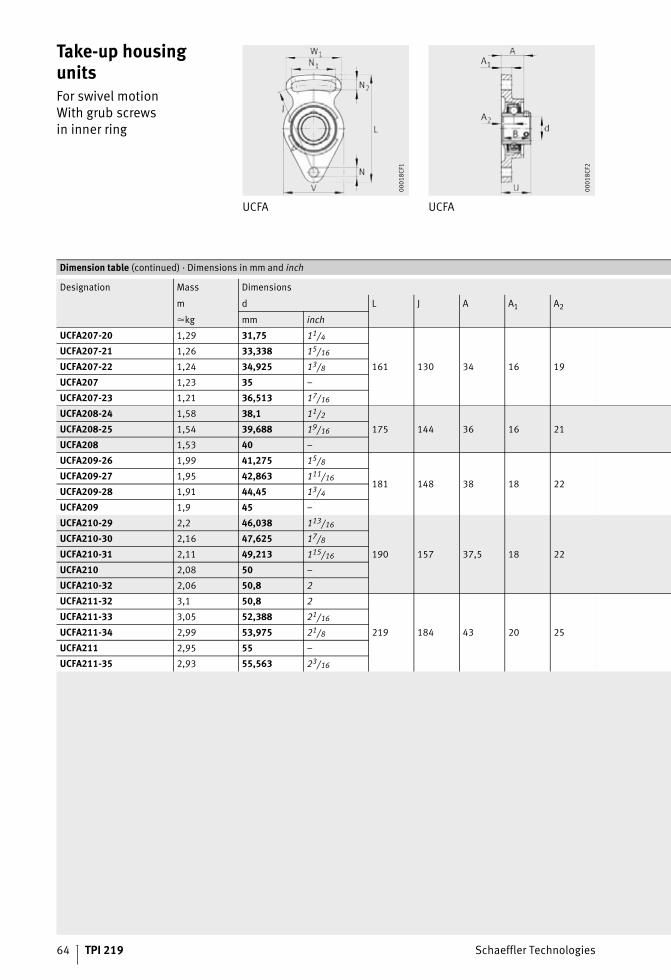
Take-up housing unitsFor swivel motionWith grub screwsin inner ring
UCFA UCFA
00
01
8C
F1
00
01
8C
F2
Dimension table · Dimensions in mm and inch
Designation Mass Dimensions
m d L J A A1 A2
�kg mm inch
UCFA201 0,45 12 –
98 78 25,5 12 15
UCFA201-08 0,45 12,7 1/2
UCFB202-09 0,44 14,288 9/16
UCFA202 0,44 15 –
UCFA202-10 0,43 15,875 5/8
UCFA203 0,43 17 –
UCFA203-11 0,42 17,463 11/16
UCFA204-12 0,41 19,05 3/4
UCFA204 0,41 20 –
UCFA205-13 0,67 20,638 13/16
125 98 27 14 16
UCFA205-14 0,66 22,225 7/8
UCFA205-15 0,64 23,813 15/16
UCFA205 0,63 25 –
UCFA205-16 0,62 25,4 1
UCFA206-17 0,94 26,988 11/16
144 117 31 14 18
UCFA206-18 0,92 28,575 11/8
UCFA206 0,9 30 –
UCFA206-19 0,9 30,163 13/16
UCFA206-20 0,88 31,75 11/4
Schaeffler Technologies TPI 219 63
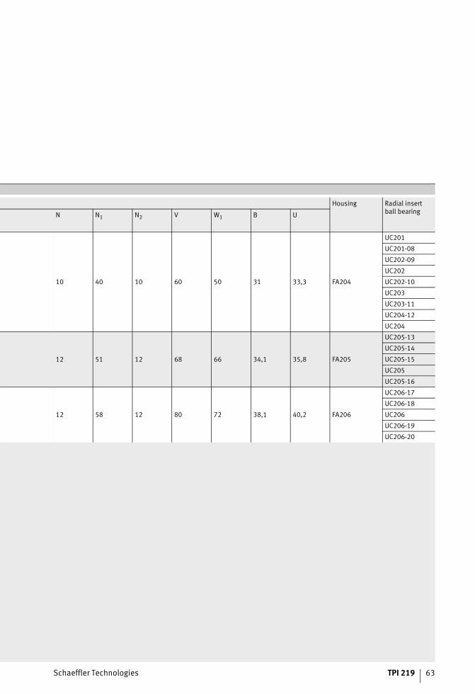
Housing Radial insertball bearing
N N1 N2 V W1 B U
10 40 10 60 50 31 33,3 FA204
UC201
UC201-08
UC202-09
UC202
UC202-10
UC203
UC203-11
UC204-12
UC204
12 51 12 68 66 34,1 35,8 FA205
UC205-13
UC205-14
UC205-15
UC205
UC205-16
12 58 12 80 72 38,1 40,2 FA206
UC206-17
UC206-18
UC206
UC206-19
UC206-20
64 TPI 219 Schaeffler Technologies
Take-up housing unitsFor swivel motionWith grub screwsin inner ring
UCFA UCFA
00
01
8C
F1
00
01
8C
F2
Dimension table (continued) · Dimensions in mm and inch
Designation Mass Dimensions
m d L J A A1 A2
�kg mm inch
UCFA207-20 1,29 31,75 11/4
161 130 34 16 19
UCFA207-21 1,26 33,338 15/16
UCFA207-22 1,24 34,925 13/8
UCFA207 1,23 35 –
UCFA207-23 1,21 36,513 17/16
UCFA208-24 1,58 38,1 11/2
175 144 36 16 21UCFA208-25 1,54 39,688 19/16
UCFA208 1,53 40 –
UCFA209-26 1,99 41,275 15/8
181 148 38 18 22UCFA209-27 1,95 42,863 111/16
UCFA209-28 1,91 44,45 13/4
UCFA209 1,9 45 –
UCFA210-29 2,2 46,038 113/16
190 157 37,5 18 22
UCFA210-30 2,16 47,625 17/8
UCFA210-31 2,11 49,213 115/16
UCFA210 2,08 50 –
UCFA210-32 2,06 50,8 2
UCFA211-32 3,1 50,8 2
219 184 43 20 25
UCFA211-33 3,05 52,388 21/16
UCFA211-34 2,99 53,975 21/8
UCFA211 2,95 55 –
UCFA211-35 2,93 55,563 23/16
Schaeffler Technologies TPI 219 65
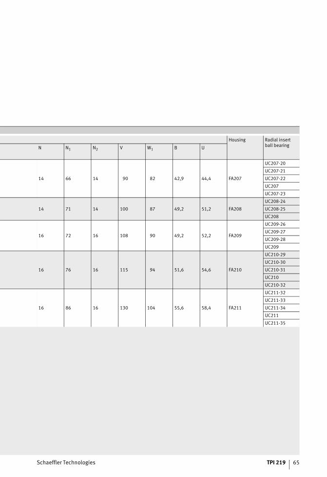
Housing Radial insertball bearing
N N1 N2 V W1 B U
14 66 14 90 82 42,9 44,4 FA207
UC207-20
UC207-21
UC207-22
UC207
UC207-23
14 71 14 100 87 49,2 51,2 FA208
UC208-24
UC208-25
UC208
16 72 16 108 90 49,2 52,2 FA209
UC209-26
UC209-27
UC209-28
UC209
16 76 16 115 94 51,6 54,6 FA210
UC210-29
UC210-30
UC210-31
UC210
UC210-32
16 86 16 130 104 55,6 58,4 FA211
UC211-32
UC211-33
UC211-34
UC211
UC211-35