Embed Size (px)
Citation preview

NATL INST. OF STAND & TECHI
RJ.fi
A11105isurement Services:
MIST
PUBLICATIONS
Radiance Temperature Calibrations
U.S. Department of CommerceQC Technology Administration
100 National Institute of Standards and Technology
U57
!0 250-43
I988

rhe National Institute of Standards and Technology was established in 1988 by Congress to "assist industry in
the development of technology . . . needed to improve product quality, to modernize manufacturing processes,
to ensure product reliability . . . and to facilitate rapid commercialization ... of products based on new scientific
discoveries."
NIST, originally founded as the National Bureau of Standards in 1901, works to strengthen U.S. industry's
competitiveness; advance science and engineering; and improve public health, safety, and the environment. One
of the agency's basic functions is to develop, maintain, and retain custody of the national standards of
measurement, and provide the means and methods for comparing standards used in science, engineering,
manufacturing, commerce, industry, and education with the standards adopted or recognized by the Federal
Government.
As an agency of the U.S. Commerce Department's Technology Administration, NIST conducts basic and
applied research in the physical sciences and engineering, and develops measurement techniques, test
methods, standards, and related services. The Institute does generic and precompetitive work on new and
advanced technologies. NIST's research facilities are located at Gaithersburg, MD 20899, and at Boulder, CO 80303.
Major technical operating units and their principal activities are listed below. For more information contact the
Publications and Program Inquiries Desk, 301-975-3058.
Office of the Director• National Quality Program
• International and Academic Affairs
Technology Services• Standards Services
• Technology Partnerships
• Measurement Services
• Technology Innovation
• Information Services
Advanced Technology Program• Economic Assessment
• Information Technology and Applications
• Chemical and Biomedical Technology
• Materials and Manufacturing Technology
• Electronics and Photonics Technology
Manufacturing Extension PartnershipProgram• Regional Programs
• National Programs
• Program Development
Electronics and Electrical EngineeringLaboratory• Microelectronics
• Law Enforcement Standards
• Electricity
• Semiconductor Electronics
• Electromagnetic Fields'
• Electromagnetic Technology1
• Optoelectronics1
Chemical Science and TechnologyLaboratory• Biotechnology
• Physical and Chemical Properties2
• Analytical Chemistry
• Process Measurements
• Surface and Microanalysis Science
Physics Laboratory• Electron and Optical Physics
• Atomic Physics
• Optical Technology
• Ionizing Radiation
• Time and Frequency'
• Quantum Physics'
Materials Science and EngineeringLaboratory• Intelligent Processing of Materials
• Ceramics
• Materials Reliability'
• Polymers
• Metallurgy
• NIST Center for Neutron Research
Manufacturing EngineeringLaboratory• Precision Engineering
• Automated Production Technology
• Intelligent Systems
• Fabrication Technology
• Manufacturing Systems Integration
Building and Fire ResearchLaboratory• Structures
• Building Materials
• Building Environment
• Fire Safety Engineering
• Fire Science
Information Technology Laboratory• Mathematical and Computational Sciences
2
• Advanced Network Technologies
• Computer Security
• Information Access and User Interfaces
• High Performance Systems and Services
• Distributed Computing and Information Services
• Software Diagnostics and Conformance Testing
'At Boulder, CO 80303.2Some elements at Boulder, CO.
NIST Special Publication 250-43
NIST MEASUREMENT SERVICES:Radiance Temperature Calibrations
Charles E. Gibson, Benjamin K. Tsai, and Albert C. Parr
Optical Technology Division
Physics Laboratory
National Institute of Standards and TechnologyGaithersburg, MD 20899-0001
January 1998
U.S. DEPARTMENT OF COMMERCEWilliam M. Daley, Secretary
Technology AdministrationGary R. Bachula, Acting Under Secretary for Technology
National Institute of Standards and TechnologyRaymond G. Kammer, Director

National Institute of Standards and Technology Special Publication 250-43
Natl. Inst. Stand. Technol. Spec. Publ. 250-43, 123 pages (Jan. 1998)
CODEN: NSPUE2
U.S. GOVERNMENT PRINTING OFFICEWASHINGTON: 1998
For sale by the Superintendent of Documents, U.S. Government Printing Office, Washington, DC 20402-9325

PREFACE
The calibration and related measurement services of the National Institute of Standards and
Technology are intended to assist the makers and users of precision measuring instruments in
achieving the highest possible levels of accuracy, quality, and productivity. NIST offers over 300
different calibrations, special tests, and measurement assurance services. These services allow
customers to directly link their measurement systems to measurement systems and standards
maintained by NIST. These services are offered to the public and private organizations alike.
They are described in NIST Special Publication (SP) 250, NIST Calibration Services Users
Guide.
The Users Guide is supplemented by a number of Special Publications (designated as the "SP250
Series") that provide detailed descriptions of the important features of specific NIST calibration
services. These documents provide a description of the: (1) specifications for the services; (2)
design philosophy and theory; (3) NIST measurement system; (4) NIST operational procedures;
(5) assessment of the measurement uncertainty including random and systematic errors and an
error budget; and (6) internal quality control procedures used by NIST. These documents will
present more detail than can be given in NIST calibration reports, or than is generally allowed in
articles in scientific journals. In the past, NIST has published such information in a variety of
ways. This series will make this type of information more readily available to the user.
This document, SP250-43 (1997), NIST Measurement Services: Radiance Temperature
Calibrations, is a revision of SP250-7 (1987). It covers the calibration of radiance temperature
standards for disappearing filament optical pyrometers, ribbon filament lamps, and radiation
thermometers (test numbers 35010C-35070S in SP250, NIST Calibration Services Users Guide).
Inquiries concerning the technical content of this document or the specifications for these
services should be directed to the author or to one of the technical contacts cited in SP250.
NIST welcomes suggestions on how publications such as this might be made more useful.
Suggestions are also welcome concerning the need for new calibrations services, special tests,
and measurement assurance programs.
Stanley D. Rasberry
Director
Measurement Services
Katharine B. Gebbie
Director
Physics Laboratory
iii
ABSTRACT
This document describes the realization and dissemination of the International Temperature Scale
of 1990 (ITS-90) above 700 °C at the National Institute of Standards and Technology (NIST). Byusing fundamental principles of blackbody physics, the ITS-90 scale is first fixed at the freezing
point of gold (790= 1064.18 °C) and is then extended to temperatures between 700 °C and
2700 °C by determining the ratio of the spectral radiance of a tungsten ribbon filament lamp to
that of a gold fixed-point blackbody at a wavelength of 655.3 nm. A description of the facilities
in the NIST Radiance Temperature Calibration Laboratory is given, along with a discussion of
the wavelength calibration, size of source, and linearity issues. The use and calibration of
radiance temperature standards are explained. Values of stability and uncertainties in the scale
are reported. The expanded uncertainties (k = 2) at 800 °C and 2300 °C are 0.6 °C and 1.4 °C for
ribbon filament lamps, 4 °C and 7 °C for disappearing filament optical pyrometers, and 2 °C and
3 °C for infrared radiation thermometers.
KEYWORDS: gold-point blackbody, International Temperature Scale (ITS-90),
pyrometers, pyrometry, radiance temperature calibration, radiation
thermometry, tungsten ribbon filament lamps
iv
TABLE OF CONTENTS
Abstract iv
1. Introduction 1
2. Measurement theory 4
3. Realization of the U.S. national scale of radiance temperature 9
3. 1 1990 NIST scale of radiance temperature 9
3.2 Temperature standards 9
3.2.1 Gold-point blackbody 9
3.2.2 Tungsten ribbon filament lamps 11
3.2.3 Working standard lamps 14
3.2.4 Variable-temperature blackbody 15
3.3 NIST photoelectric pyrometer 19
3.3.1 Measurement system 19
3.3.2 Optical system 21
3.3.3 Interference filters 22
3.3.4 Detectors 23
3.3.5 Linearity of response 24
3.3.6 Wavelength calibration 27
3.3.7 Size of source effect 29
3.4 Radiance temperature scale uncertainties 30
3.5 Quality control 32
4. Tungsten ribbon filament lamp calibrations 37
4. 1 Lamp preparation 37
4.2 Lamp calibration 37
4.3 Lamp data analysis 38
4.4 Lamp calibration uncertainty 40
5. Disappearing filament optical pyrometer calibrations 44
5.1 Optical pyrometer preparation 44
5.2 Optical pyrometer calibration 44
5.3 Optical pyrometer data analysis 44
5.4 Optical pyrometer calibration uncertainty 45
v
TABLE OF CONTENTS (continued)
6. Radiation thermometer calibrations 49
6.1 Radiation thermometer preparation 49
6.2 Radiation thermometer calibration 49
6.3 Radiation thermometer data analysis 49
6.4 Radiation thermometer calibration uncertainty 49
7. Modifications to the NIST photoelectric pyrometer 53
Acknowledgments 54
References 55
Appendix A: Ribbon filament lamp sample calibration report Al
Appendix B: Optical pyrometer sample calibration report B
1
Appendix C: Radiation thermometer sample calibration report CI
Appendix D: Radiance temperature measurement services laboratory procedure manual Dl
Appendix E: How to request radiance temperature calibration services El
vi
LIST OF FIGURES
Figure 1 Schematic of optics for the NIST photoelectric pyrometer 4
Figure 2 Blackbody spectral distribution. As the temperature increases, the peak moves
toward shorter wavelengths, and the slope increases at each wavelength 5
Figure 3 Schematic of gold-point blackbody 10
Figure 4 Gold-point blackbody liquid-to-solid phase transition 1
1
Figure 5 Gold-point blackbody control system 12
Figure 6 Schematic of lamp current monitoring system 13
Figure 7 Typical lamp currents for the General Electric 30A/T24/6 ribbon filament lamp 14
Figure 8 Ribbon filament lamp 16
Figure 9 Calibration history of the working standard (no. SL20) 17
Figure 10 Schematic of the variable temperature blackbody 17
Figure 1 1 Variable temperature blackbody control system 18
Figure 12 Spatial scan of the variable temperature blackbody at 2000 °C. The temperature
differences are from the center position (0,0) 18
Figure 13 Variable temperature blackbody PID control. After decreasing the set point by
100 °C, the blackbody stabilizes in less than 10 min 19
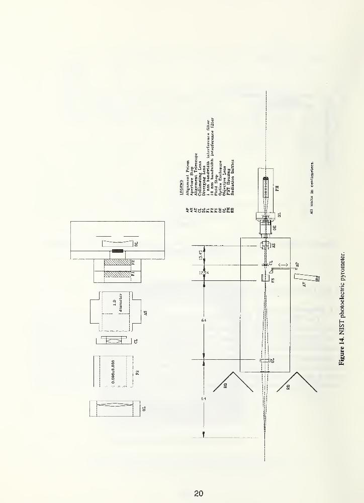
Figure 14 NIST photoelectric pyrometer 20
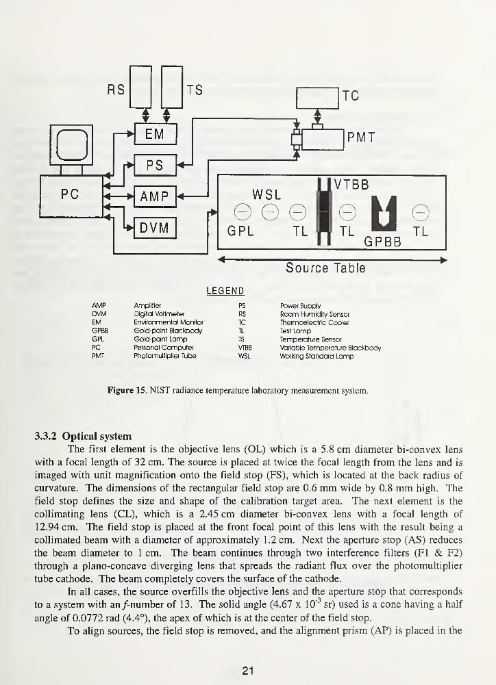
Figure 15 NIST radiance temperature laboratory measurement system 21
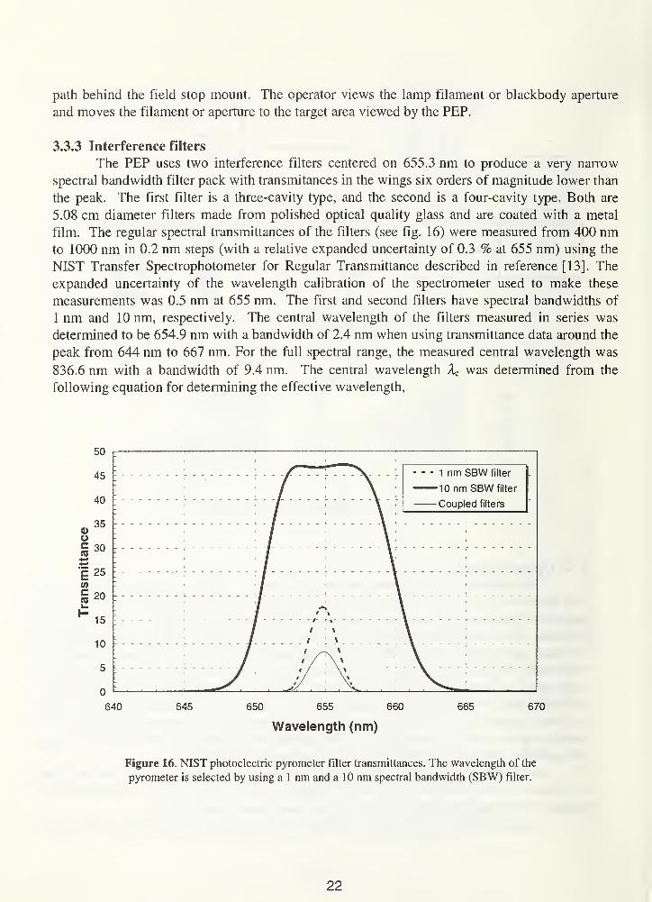
Figure 16 NIST photoelectric pyrometer filter transmittances. The wavelength of the
pyrometer is selected by using a 1 nm and a 10 nm spectral bandwidth (SBW)
filter 22
Figure 17 The linearity correction factors for the PEP 25
Figure 18 Relative spectral response of the NIST photoelectric pyrometer 28
Figure 19 The size of source corrections for the variable temperature blackbody to the
working standard lamp comparison and the working standard lamp to the
gold-point blackbody 30
Figure 20 Calibration history of the ribbon filament lamp check standards 35
Figure 21 Calibration history of the radiation thermometer check standard
(Minolta Cyclops 52) 36
Figure 22 Calculation of 7COrr from Tmean and AI/AT 39
Figure 23 Graph of rmean and AI/AT 40
Figure 24 Modified NIST photoelectric pyrometer 53
vii
LIST OF TABLES
Table 1 Radiance temperature calibration services 2
Table 2 Calibration uncertainties 3
Table 3 Current amplifier normalization factors 24
Table 4 Detector system correction factors and linearity coefficients 25
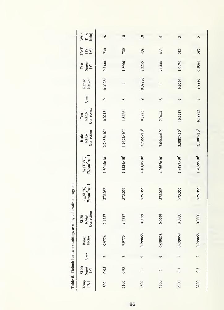
Table 5 Default hardware settings used by calibration program 26
Table 6 Corrections (°C) to the radiance temperature at 900 nm and at 1000 nm 29
Table 7 Typical values of WS variables and parameters 33
Table 8 Uncertainty budget for the NIST WS lamp spectral radiance realization 34
Table 9 Typical values of TL variables and parameters 42
Table 10 Uncertainty budget for the TL spectral radiance calibration 43
Table 1 1 Typical values of DF variables and parameters 47
Table 12 Uncertainty budget for the DF spectral radiance calibration 48
Table 1 3 Typical values of RT variables and parameters 51
Table 14 Uncertainty budget for the RT spectral radiance calibration 52
viii
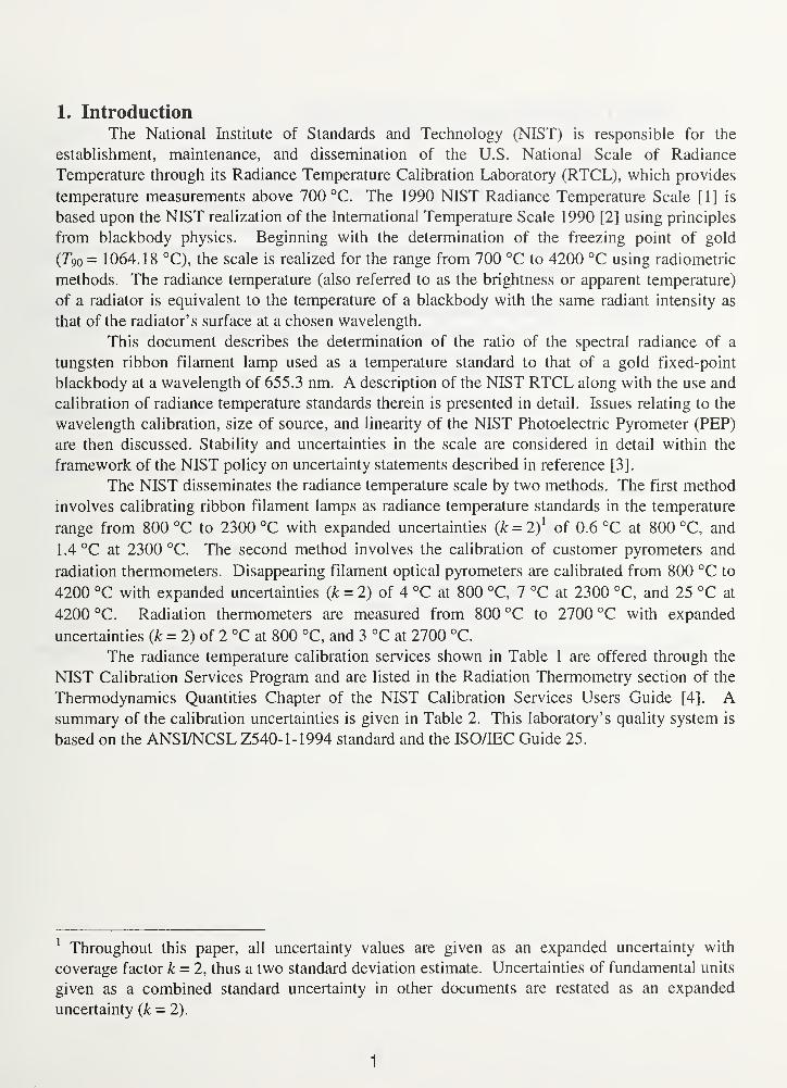
1. Introduction
The National Institute of Standards and Technology (NIST) is responsible for the
establishment, maintenance, and dissemination of the U.S. National Scale of Radiance
Temperature through its Radiance Temperature Calibration Laboratory (RTCL), which provides
temperature measurements above 700 °C. The 1990 NIST Radiance Temperature Scale [1] is
based upon the NIST realization of the International Temperature Scale 1990 [2] using principles
from blackbody physics. Beginning with the determination of the freezing point of gold
(T9o = 1064.18 °C), the scale is realized for the range from 700 °C to 4200 °C using radiometric
methods. The radiance temperature (also referred to as the brightness or apparent temperature)
of a radiator is equivalent to the temperature of a blackbody with the same radiant intensity as
that of the radiator's surface at a chosen wavelength.
This document describes the determination of the ratio of the spectral radiance of a
tungsten ribbon filament lamp used as a temperature standard to that of a gold fixed-point
blackbody at a wavelength of 655.3 nm. A description of the NIST RTCL along with the use and
calibration of radiance temperature standards therein is presented in detail. Issues relating to the
wavelength calibration, size of source, and linearity of the NIST Photoelectric Pyrometer (PEP)
are then discussed. Stability and uncertainties in the scale are considered in detail within the
framework of the NIST policy on uncertainty statements described in reference [3].
The NIST disseminates the radiance temperature scale by two methods. The first method
involves calibrating ribbon filament lamps as radiance temperature standards in the temperature
range from 800 °C to 2300 °C with expanded uncertainties (k = 2)[
of 0.6 °C at 800 °C, and
1.4 °C at 2300 °C. The second method involves the calibration of customer pyrometers and
radiation thermometers. Disappearing filament optical pyrometers are calibrated from 800 °C to
4200 °C with expanded uncertainties (k = 2) of 4 °C at 800 °C, 7 °C at 2300 °C, and 25 °C at
4200 °C. Radiation thermometers are measured from 800 °C to 2700 °C with expanded
uncertainties (k = 2) of 2 °C at 800 °C, and 3 °C at 2700 °C.
The radiance temperature calibration services shown in Table 1 are offered through the
NIST Calibration Services Program and are listed in the Radiation Thermometry section of the
Thermodynamics Quantities Chapter of the NIST Calibration Services Users Guide [4]. Asummary of the calibration uncertainties is given in Table 2. This laboratory's quality system is
based on the ANSI/NCSL Z540-1-1994 standard and the ISO/TEC Guide 25.
Throughout this paper, all uncertainty values are given as an expanded uncertainty with
coverage factor k = 2, thus a two standard deviation estimate. Uncertainties of fundamental units
given as a combined standard uncertainty in other documents are restated as an expanded
uncertainty (k = 2).
1
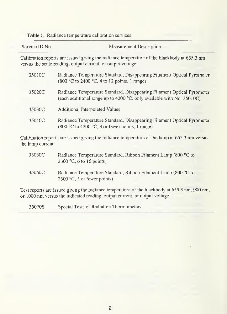
Table 1. Radiance temperature calibration services
Service ID No. Measurement Description
Calibration reports are issued giving the radiance temperature of the blackbody at 655.3 nmversus the scale reading, output current, or output voltage.
350 IOC Radiance Temperature Standard, Disappearing Filament Optical Pyrometer
(800 °C to 2400 °C, 4 to 12 points, 1 range)
35020C Radiance Temperature Standard, Disappearing Filament Optical Pyrometer
(each additional range up to 4200 °C, only available with No. 350 10C)
35030C Additional Interpolated Values
35040C Radiance Temperature Standard, Disappearing Filament Optical Pyrometer
(800 °C to 4200 °C, 3 or fewer points, 1 range)
Calibration reports are issued giving the radiance temperature of the lamp at 655.3 nm versus
the lamp current.
35050C Radiance Temperature Standard, Ribbon Filament Lamp (800 °C to
2300 °C, 6 to 16 points)
35060C Radiance Temperature Standard, Ribbon Filament Lamp (800 °C to
2300 °C, 5 or fewer points)
Test reports are issued giving the radiance temperature of the blackbody at 655.3 nm, 900 nm,
or 1000 nm versus the indicated reading, output current, or output voltage.
35070S Special Tests of Radiation Thermometers
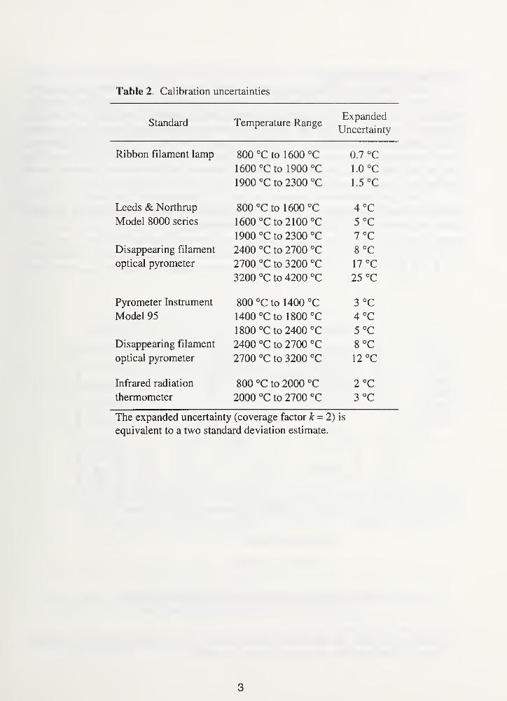
Table 2. Calibration uncertainties
Standard Temperature RangeJJ/A UcUlllCU-
1 Jncprtaintv
Ribbon filament lamp 800 °C to 1600 °C 0.7 °C
1600 °C to 1900 °C 1.0 °C
1900 °C to 2300 °C 1.5 °C
Leeds & Northrup 800 °C to 1600 °C 4°CModel 8000 series 1600 °C to 2100 °C 5°C
1900 °C to 2300 °C 7°CDisappearing filament 2400 °C to 2700 °C 8 °C
optical pyrometer 2700 °C to 3200 °C 17 °C
3200 °C to 4200 °C 25 °c
Pyrometer Instrument 800 °C to 1400 °C 3 °C
Model 95 1400 °C to 1800 °C 4 °C
1800 °C to 2400 °C 5 °C
Disappearing filament 2400 °C to 2700 °C 8°Coptical pyrometer 2700 °C to 3200 °C 12 °C
Infrared radiation 800 °C to 2000 °C 2°Cthermometer 2000 °C to 2700 °C 3 °C
The expanded uncertainty (coverage factor k = 2) is
equivalent to a two standard deviation estimate.
3

2. Measurement theory
Temperatures above the freezing point of silver (1234.93 K or 961.78 °C) are defined on
the International Temperature Scale of 1990 (ITS-90) [2] in terms of the ratio of spectral
radiances of two blackbody sources, one of which is maintained at the temperature of freezing
silver, gold (1337.33 K or 1064.18 °C), or copper (1357.77 K or 1084.62 °C). The 1990 NIST
Scale of Radiance Temperature (1990 NIST) is a realization of the ITS-90 using a gold fixed-
point blackbody. In this section, the blackbody temperature will be defined in terms of the
spectral radiance. Using the signal measurement equation, the measurement equation for the
calibration of a transfer standard will be derived.
The signal measurement equation, defined by Nicodemus and Kostkowski in 1978 [5],
relates the detector signal output, S [V] , to the source flux input parameters through a detector
responsivity term, Rx [AW 1
], by the integral relationship,
S =J
j*JRx
LA
• dA • cos 6 dco 6A , (1)
A a A
I
LEGEND
AS Aperture StopCL Collimating LensDL Diverging LensFl 1 nm bandwidth interference filter
F2 10 nm bandwidth interference filter
FS Field StopOL Objective Lens
Figure 1. Schematic of optics for the NIST photoelectric pyrometer.
2 As an aid to the reader, the appropriate coherent SI unit in which a quantity should be expressed
is indicated in brackets when the quantity is first introduced.
4
where Lx [Wm^sr 1
] is the spectral radiance, dA [m] is the wavelength band, 9 [rad] is the angle
between the aperture normal and the line connecting the aperture centers, do [sr] is the
differential solid angle originating at the source aperture as defined by the detector aperture, and
dA [m2] is the differential source aperture area. For the NIST PEP in figure 1 , the spectral
responsivity Rx includes the spectral transmittance of the interference filters, the spectral
transmittance of all other optical elements, and the spectral responsivity of the detector. In terms
of its specific components, the spectral responsivity is
where txol is the spectral transmittance of the objective lens, Ta,cl is the spectral transmittance of
the collimating lens, t^fi is the spectral transmittance of the 1 nm bandpass interference filter,
Ta,f2 is the spectral transmittance of the 10 nm bandpass interference filter, t^dl is the spectral
transmittance of the diverging lens, Ta,ec is the spectral transmittance of the evacuated window
cell, and Rx,pep is the detector absolute spectral responsivity.
200 600 1000 1400
Wavelength (nm)
1800 2200
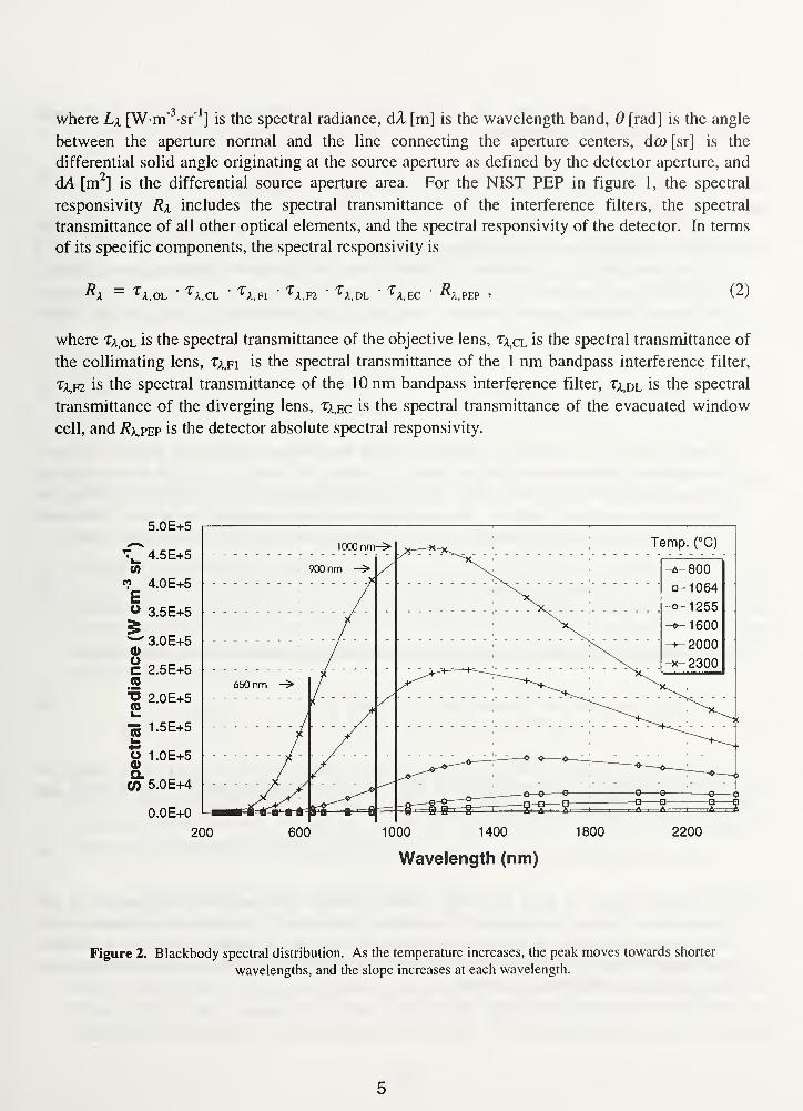
Figure 2. Blackbody spectral distribution. As the temperature increases, the peak moves towards shorter
wavelengths, and the slope increases at each wavelength.
5
Spectral radiance La is the radiant power contained in a defined area, solid angle,
direction, and wavelength interval,
LA= d
30 / dA cos a dp dX , (3)
where <Z> is the radiant flux [W], A is the source area, a is the plane angle between the surface
normal and the direction of propagation [rad], (3 is the solid angle about that direction [sr], and X
is the wavelength [m]. A few blackbody distributions from 250 nm to 2500 nm between 800 °C
and 2300 °C are illustrated in figure 2. For an ideal blackbody in a vacuum environment,
the relation between spectral radiance, wavelength, and temperature is given by the Planck
equation [6],
T - CJk (A)
X5• (exp(c
2/(X • T)) - 1)
'
{ )
where c\i is the first radiation constant in radiance form with a value of 1 19.1044 Wnm2, ci is
the second radiation constant with a value of 1.4388 x 10"7 nm-K [7], X is the wavelength in
vacuum, and T is the temperature [K]. The Planck equation in the form of eq (4) is the definition
for an ideal blackbody radiator. When using a non-ideal blackbody such as a fixed-point
blackbody to realize the temperature scale, the following form of the Planck equation is used,
L = £x '
°XL(5)
n\ X5(exp(c
2 l(nx X • T)) - 1)
'
and temperature is defined as a function of spectral radiance using the following equation
T(X, LA ) = t
^. , (6)
nx
X \n{\ + e kclL I n
kX Lj
where £x is the spectral emissivity of the blackbody (which is equal to unity in the case of an
ideal blackbody), A is the wavelength in air, and nx is the refractive index of air at 15 °C and
101,325 Pa. From the Cauchy [8] formula,
n x=1 + (2726.43 + 12.288 nm 2
/(A2xl0-
6)+ 0.3555 nm 4
/(A4xlO"
12))xlO"
7
, (7)
the refractive index of air at 655.3 nm is about 1.00028. The temperatures described in this
document are radiance temperatures. The radiance temperature of a radiator is equivalent to the
temperature of a blackbody with the same radiant intensity of the radiator's surface at a specified
wavelength. The relationship between the radiance temperature and the true or thermodynamic
temperature of a blackbody is given by:
6
where 7 is the thermodynamic temperature, 7\ is the radiance temperature, X is the mean
effective wavelength of the NIST PEP (655.3 nm), and £\ is the estimated emissivity of the
blackbody (0.99).
Determination of the spectral radiance temperature of a working standard (WS) lamp
requires measurement of the ratio r\,
rx
= 'WS
' Ail
(9)
of the signals from the transfer standard and the goldpoint blackbody (Au) with the NIST PEP.
From eq (2), this measured ratio is actually
\\\RX{L
Xcos0
s dmdAXs dAX As (o
\\\RX
{LX
cos0s
dft> dAs )Au dA
'
To simplify the complex expression in eq (10), it is assumed that the spectral radiances L^ws and
Lx,Au, spectral responsivities ^a,ws and R^au, and amplifier gains Gws and Gau are independent of
both direction and spatial location. Furthermore, these three variables can be defined by unique
for the transfer source and the gold-point blackbody at equivalent wavelengths (to be defined
later) over the same small wavelength band dA. The solid angle terms can be replaced with the
definition of the solid angle,
D
where Ad is the detector area [m2], 0d is the angle between the optical axis and the normal to the
detector surface [rad], and D is the distance between the detector area and the source area [m].
Assuming that the areas are independent of direction and that the solid angles are independent of
area or spatial location, this ratio then becomes
ri
=cos 6
S
cos G e
cos 6d ),
cos 6d )
DD
Au(12)
WS
where A s is the source area [m2], 0S is the angle between the optical axis and the normal to the
source surface [rad], /?a,ws is the detector responsivity when viewing the transfer source, and
Rx,au is the detector responsivity when viewing the gold-point blackbody. The spectral
responsivities /?a,ws and 7?a,au are assumed to be equal. If the source aperture areas dATs and
7
(Mau, source solid angles da>ws and dfi)Au, and the source inclination angles 9ws and 0au are the
same for measuring both the transfer standard and the gold-point blackbody, the measured ratio
simplifies to the expression,
L'A,WS (Xws
)
L(13)
'A.Au
This relationship is the defining equation for the ITS-90 above 1337.33 K. In terms of eq (4), it
can be written at a discrete wavelength, X, as
where La(Tws) and L^(TAu) are the spectral radiances of the two blackbodies at temperatures Tand rAu , ?au is the temperature of freezing gold defined as 1337.33 K, and r\ is their ratio. In
principle, a measurement of the ratio at a discrete wavelength with a linear response instrument
yields the value of T.
The radiance temperature scale is typically maintained and disseminated on tungsten
ribbon filament lamps, which possess a repeatable lamp current versus radiance temperature
relationship. At the NIST, a pyrometer system is presently being used with a mean effective
wavelength of 655.3 nm. This method requires that the pyrometer relative spectral response
extends only over a small spectral range, or is known accurately enough to determine the
wavelength at which the integrands of eq (10) have the same ratio as the integrals. Equation (13)
above is an approximation, and, in practice, corrections, which will be presented in the next
section, are used.
M^ws) =exp(c
2l(n
x X 7Au ))— 1
M^aJ exP(c 2f(nx
rws)) - 1'
(14)
e
3. Realization of the U.S. national scale of radiance temperature
3.1 1990 NIST scale of radiance temperature
The reference temperature standard, a gold fixed-point blackbody (Au) with a
temperature (Tau) of 1064.18 °C (1337.33 K), and the Planck radiation law are used to realize
and disseminate the 1990 NIST Radiance Temperature Scale. Equation (5) is used to calculate
the spectral radiance La,au(A, 7au) of the fixed-point blackbody for A = 655.3 nm in all the
measurements of this calibration facility. Measurements are performed from 800 °C to 2300 °C
for lamps, from 800 °C to 2700 °C for radiation thermometers, and extrapolated to 4200 °C for
some disappearing filament optical pyrometers.
The NIST PEP is the transfer device used to compare the spectral radiances of the sources
by the direct substitution method. The signals are corrected for size of source, amplifier gain,
and linearity. With these corrections, the spectral radiance and the radiance temperature can be
determined from eqs (12) and (13). The NIST PEP is a filtered radiometer that uses two
interference filters to select the bandpass. The spectral bandwidth is 5 nm with a mean effective
wavelength of 655.3 nm. A photomultiplier tube with an S-20 spectral response is used in the dc
mode. The measurement spot size is a 0.6 mm by 0.8 mm rectangle.
A high stability vacuum lamp operated at a single radiance temperature of approximately
1255 °C is the working standard (WS). By equating eqs (9) and (13), the spectral radiance ratio is
Lx (TAu )
'WSl
'Au
(15)
After applying correction factors to the signals in eq (15) for amplifier calibration (Ca), linearity
(CO, and size of source (Cs), the spectral radiance of the WS 1 lamp can be written as
All
( c )2 -15
nx
A expc2 - 1
K
nx • k TAu ^
(^A ' Cl '
' ^)\VS
(CA CL ' Q ' G )au
(16)
References regarding linearity issues are presented in Section 3.3.5. The uncertainty analysis in
Section 3.6 can then be derived from eq (15) for the NIST radiance temperature scale up to the
calibration of the spectral radiance of the working standard lamp.
3.2 Temperature standards
3.2.1 Gold-point blackbody
In the RTCL, a gold fixed-point blackbody with a calculated emissivity of 0.9999.
designed and built by the NIST Optical Technology Division, is the primary standard used to
realize the 1990 NIST Radiance Temperature Scale. The blackbody in figure 3 consists of a
graphite cavity, a crucible of gold, and a cylindrical heat-pipe furnace. The cavity, which is
9
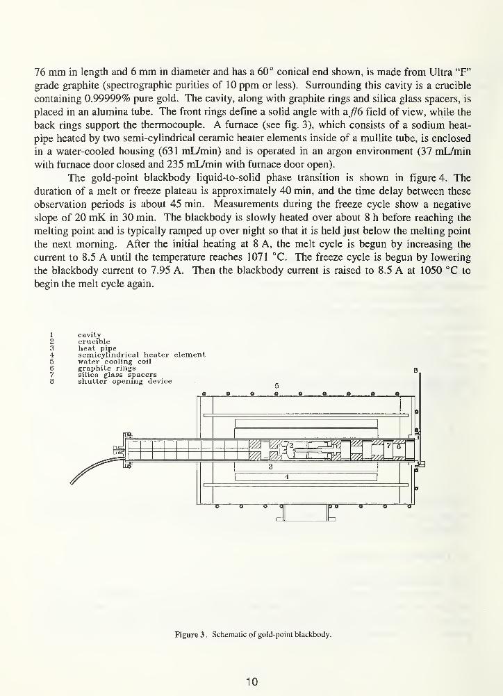
76 mm in length and 6 mm in diameter and has a 60° conical end shown, is made from Ultra "F"
grade graphite (spectrographic purities of 10 ppm or less). Surrounding this cavity is a crucible
containing 0.99999% pure gold. The cavity, along with graphite rings and silica glass spacers, is
placed in an alumina tube. The front rings define a solid angle with a f/6 field of view, while the
back rings support the thermocouple. A furnace (see fig. 3), which consists of a sodium heat-
pipe heated by two semi-cylindrical ceramic heater elements inside of a mullite tube, is enclosed
in a water-cooled housing (63 1 mL/min) and is operated in an argon environment (37 mL/min
with furnace door closed and 235 mL/min with furnace door open).
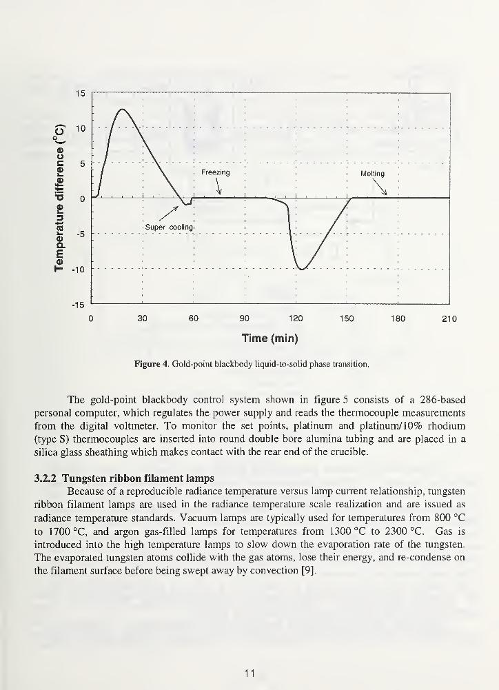
The gold-point blackbody liquid-to-solid phase transition is shown in figure 4. The
duration of a melt or freeze plateau is approximately 40 min, and the time delay between these
observation periods is about 45 min. Measurements during the freeze cycle show a negative
slope of 20 mK in 30 min. The blackbody is slowly heated over about 8 h before reaching the
melting point and is typically ramped up over night so that it is held just below the melting point
the next morning. After the initial heating at 8 A, the melt cycle is begun by increasing the
current to 8.5 A until the temperature reaches 1071 °C. The freeze cycle is begun by lowering
the blackbody current to 7.95 A. Then the blackbody current is raised to 8.5 A at 1050 °C to
begin the melt cycle again.
1 cavity2 crucible3 heat pipe4 semicyhndrical heater element5 water cooling coil6 graphite rings7 silica glass spacers8 shutter opening device
7 6
m ///,
Figure 3 . Schematic of gold-point blackbody.
10
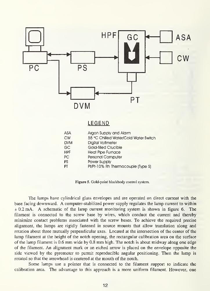
The gold-point blackbody control system shown in figure 5 consists of a 286-based
personal computer, which regulates the power supply and reads the thermocouple measurements
from the digital voltmeter. To monitor the set points, platinum and platinum/10% rhodium
(type S) thermocouples are inserted into round double bore alumina tubing and are placed in a
silica glass sheathing which makes contact with the rear end of the crucible.
3.2.2 Tungsten ribbon filament lamps
Because of a reproducible radiance temperature versus lamp current relationship, tungsten
ribbon filament lamps are used in the radiance temperature scale realization and are issued as
radiance temperature standards. Vacuum lamps are typically used for temperatures from 800 °C
to 1700 °C, and argon gas-filled lamps for temperatures from 1300 °C to 2300 °C. Gas is
introduced into the high temperature lamps to slow down the evaporation rate of the tungsten.
The evaporated tungsten atoms collide with the gas atoms, lose their energy, and re-condense on
the filament surface before being swept away by convection [9].
11
DVM
LEGEND
ASA Argon Supply and Alarm
cw 55 °C Chilled Water/Cold Water Switch
DVM Digital Voltmeter
GC Gold-filled CruciPle
HPF Heat Pipe Furnace
PC Personal ComputerPS Power Supply
PT Pt/Pt-10% Rh Thermocouple (Type S)
Figure 5. Gold-point blackbody control system.
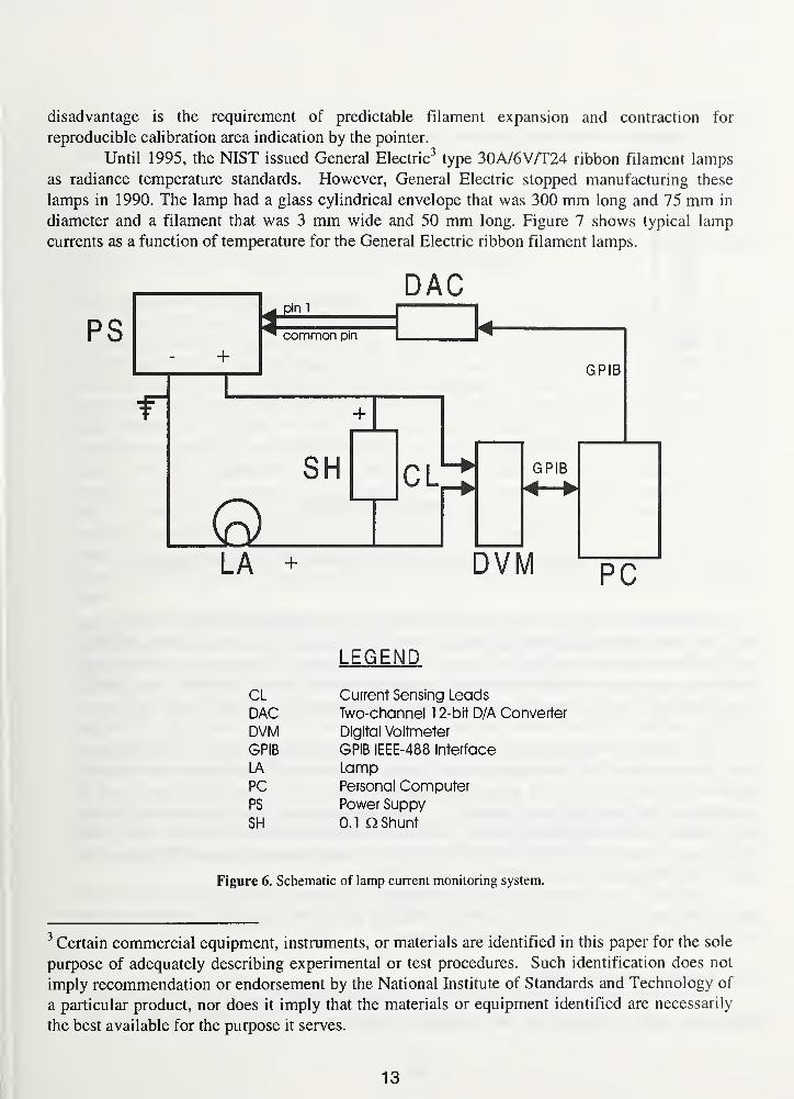
The lamps have cylindrical glass envelopes and are operated on direct current with the
base facing downward. A computer-stabilized power supply regulates the lamp current to within
± 0.2 mA. A schematic of the lamp current monitoring system is shown in figure 6. The
filament is connected to the screw base by wires, which conduct the current and thereby
minimize contact problems associated with the screw bases. To achieve the required precise
alignment, the lamps are rigidly fastened in source mounts that allow translation along and
rotation about three mutually perpendicular axes. Located at the intersection of the center of the
lamp filament at the height of the notch opening, the rectangular calibration area on the surface
of the lamp filament is 0.6 mm wide by 0.8 mm high. The notch is about midway along one edge
of the filament. An alignment mark or an etched arrow is placed on the envelope opposite the
side viewed by the pyrometer to permit reproducible angular positioning. Then the lamp is
rotated so that the arrowhead is centered at the mouth of the notch.
Some lamps use a pointer that is connected to the filament support to indicate the
calibration area. The advantage to this approach is a more uniform filament. However, one
12
disadvantage is the requirement of predictable filament expansion and contraction for
reproducible calibration area indication by the pointer.
Until 1995, the NIST issued General Electric3type 30A/6V/T24 ribbon filament lamps
as radiance temperature standards. However, General Electric stopped manufacturing these
lamps in 1990. The lamp had a glass cylindrical envelope that was 300 mm long and 75 mm in
diameter and a filament that was 3 mm wide and 50 mm long. Figure 7 shows typical lamp
currents as a function of temperature for the General Electric ribbon filament lamps.
DAC
GPIB
LA +
GPIB
PC
LEGEND
CL Current Sensing Leads
DAC Two-channel 1 2-bit D/A Converter
DVM Digital Voltmeter
GPIB GPIB IEEE-488 Interface
LA LampPC Personal ComputerPS Power Suppy
SH 0.1 a Shunt
Figure 6. Schematic of lamp current monitoring system.
Certain commercial equipment, instruments, or materials are identified in this paper for the sole
purpose of adequately describing experimental or test procedures. Such identification does not
imply recommendation or endorsement by the National Institute of Standards and Technology of
a particular product, nor does it imply that the materials or equipment identified are necessarily
the best available for the purpose it serves.
13

50
45
40
*- 35C0)
3 30Uo.
E25(0-J
20
15 -
10
500 1000 1500 2000 2500
Temperature ( C)
Figure 7. Typical lamp currents for the General Electric 30A/T24/6 ribbon filament lamp.
The NIST is currently issuing U.K. General Electric Company (GEC) lamps, although the
lamps are no longer available from this source. The GEC lamps (type 20/G and 20/V) have glass
cylindrical envelopes that are 235 mm long with a 64 mm diameter. The 20/V is a vacuum lamp
with a filament 1 mm wide by 50 mm long and requires about 10 A dc at 1500 °C. The 20/G is
a gas-filled lamp with a 2 mm wide by 30 mm long filament and requires about 20 A dc at
2300 °C.
In 1992, Type TRU 1100-2350 lamps were purchased from the Moscow Lamp Factory
(Russia) for testing as radiance temperature standards. Due to a decline in requests for radiance
temperature standard lamps, the testing was not done. At 2300 °C, about 25 A dc current is
required from the gas-filled lamp, which has a cylindrical envelope, a 2.5 mm wide by 20 mmlong filament, and an alignment pointer. The TRU lamps, which have a 35 mm silica glass
window that projects about 5 mm from the envelope, were used in addition to the GE lamp in the
NIST/VNIOFFI spectral radiance intercomparison [10].
The NIST has also bought type 24/G lamps with double silica glass windows from
Polaron Engineering LTD (U. K.) for use as working and check standards. These lamps are
similar in design and construction to the GEC lamps.
3.2.3 Working standard lamps
A vacuum tungsten ribbon filament lamp of the Quinn-Lee type [11,12] is used in the
temperature scale realization as the secondary temperature standard which maintains the
14

temperature scale between scale realizations and as the transfer standard for calibration
measurements. The temperature of the working standard lamp (serial number SL20) is
determined by spectral comparison with the gold-point blackbody. A drawing of this lamp is
shown in figure 8. This lamp is operated at a single current (7.7788 A dc) to produce a spectral
radiance about eight times higher than that of the gold-point blackbody at 655.3 nm (a radiance
temperature of about 1530 K). This lamp is stable to better than 0.1 °C over lOOh when
operated under these single-level conditions. A graph of the calibration history of the working
standard from August 1989 to February 1996 is shown in figure 9.
3.2.4 Variable-temperature blackbody
The NIST uses a commercial variable-temperature blackbody (VTBB) for its radiance
temperature transfer standard (See fig. 10). This VTBB was manufactured by Thermogage Inc.
in Frostburg, MD and was supplied with the Type II dual blackbody assembly (2.54 cm or 1 in
ID cavity), the 48 kW power supply, a control program, the model 7000-1 (4 range) optical
pyrometer, and a digital temperature computer control module. Modifications requested by the
NIST include the addition of the water-cooled semi-cylindrical mirrors, and enlarging the
extension tube opening to accommodate measurements with the NIST PEP.
The VTBB is operated between 700 °C and 2700 °C. The ranges, which are selected by
placing different size apertures on the optical control pyrometer, are the low range (700 °C to
1300 °C), the medium range (1300 °C to 1800 °C), the high range (1800 °C to 2500 °C), and the
extra high range (2500 °C to 2700 °C). The electrodes are water-cooled by using a 13 °C (55 °F)
chilled water source. Before the blackbody is turned on, argon gas displaces the air in the cavity.
When the VTBB cavity is operating, the argon exits from both the front and back extension
tubes.
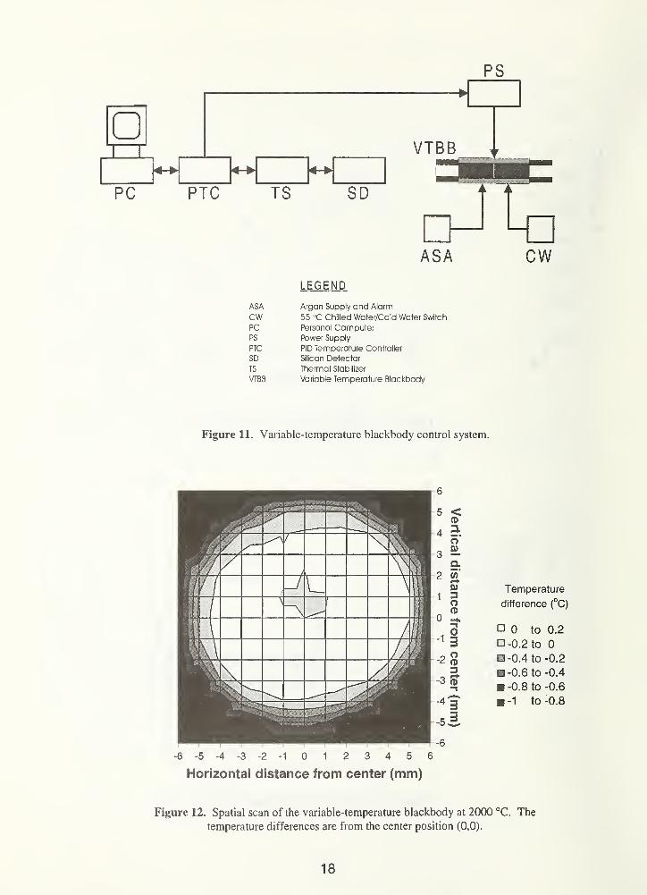
The variable-temperature blackbody control system regulates the blackbody temperature
to within ±0.1 °C (see fig. 1 1). The NIST measures the uniformity of the center partition of the
Thermogage heater elements, and uses those with a spatial uniformity of better than ± 0.2 °C at
2000 °C over an area of 10 mm diameter (see fig. 12). The blackbody heats up to the operating
point in less than 30 min and responds quickly to temperature changes (see fig. 13). The day-to-
day stability of the blackbody is better than ± 0.3 °C, and the 6-month stability is within ± 2 °C.
The VTBB operates between 800 °C and 2700 °C with an estimated emissivity of 0.99
from analytical modeling. The temperature distribution within the VTBB cavity is less than
50 °C. The blackbody cavity is composed of a single piece of graphite, which is specially
tapered for achieving high temperature uniformity. This graphite tube is cylindrically hollow on
both ends to form two 2.54 cm diameter cavities with a common partition in the center. One
cavity is used for temperature control, and the other cavity is the blackbody source.
15

16

Cylindrical sectionswith finer details
1 Quartz glass2 Grafoil3 Felt4 Graphite heater element5 Water cooling lines6 Argon line7 Control Pyrometer8 Endcap9 Extension
/
Tube dUmeler ii 2.M
All dimensions in centimeters. 14.45-
•30.16-
Figure 10. Schematic of variable-temperature blackbody.
17
PS
<h:>
PTC TS
VTBB4->
SD
ASA CWLEGEND
ASA Argon Supply and Alarm
CW 55 °C Chilled Water/Cold Water Switch
PC Personal ComputerPS Power Supply
PTC PID Temperature Controller
SD Silicon Detector
TS Thermal Stabilizer
VTBB Variable Temperature Blackbody
Figure 11. Variable-temperature blackbody control system.
-6 -5 -4 -3 -2 -1 0 1 2 3 4 5 6
Horizontal distance from center (mm)
Temperature
difference (°C)
0 to
-0.2 to
0.4 to
0.6 to
0.8 to
1 to
0.2
0
0.2
-0.4
0.6
0.8
Figure 12. Spatial scan of the variable-temperature blackbody at 2000 °C. The
temperature differences are from the center position (0,0).
18
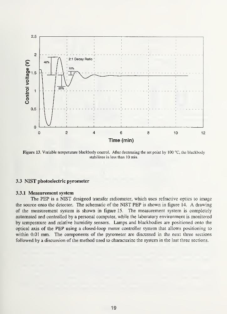
Figure 13. Variable temperature blackbody control. After decreasing the set point by 100 °C, the blackbody
stabilizes in less than 10 min.
3.3 NIST photoelectric pyrometer
3.3.1 Measurement system
The PEP is a NIST designed transfer radiometer, which uses refractive optics to image
the source onto the detector. The schematic of the NIST PEP is shown in figure 14. A drawing
of the measurement system is shown in figure 15. The measurement system is completely
automated and controlled by a personal computer, while the laboratory environment is monitored
by temperature and relative humidity sensors. Lamps and blackbodies are positioned onto the
optical axis of the PEP using a closed-loop motor controller system that allows positioning to
within 0.01 mm. The components of the pyrometer are discussed in the next three sections
followed by a discussion of the method used to characterize the system in the last three sections.
19
20
TC
PMT
WSL 1
VTBB
0 0 0 |e U eGPL TL 1 1 TL M TL
GPBB^
Source Table
LEGEND
AMP Amplifier PS Power Supply
DVM Digital Voltmeter RS Room Humidity Sensor
EM Environmental Monitor TC Thermoelectric Cooler
GPBB Gold-point Blackbody TL Test LampGPL Gold-point Lamp TS Temperature Sensor
PC Personal Computer VTBB Variable Temperature BlackbodyPMT Photomultiplier Tube WSL Working Standard Lamp
Figure 15. NIST radiance temperature laboratory measurement system.
3.3.2 Optical system
The first element is the objective lens (OL) which is a 5.8 cm diameter bi-convex lens
with a focal length of 32 cm. The source is placed at twice the focal length from the lens and is
imaged with unit magnification onto the field stop (FS), which is located at the back radius of
curvature. The dimensions of the rectangular field stop are 0.6 mm wide by 0.8 mm high. The
field stop defines the size and shape of the calibration target area. The next element is the
collimating lens (CL), which is a 2.45 cm diameter bi-convex lens with a focal length of
12.94 cm. The field stop is placed at the front focal point of this lens with the result being a
collimated beam with a diameter of approximately 1.2 cm. Next the aperture stop (AS) reduces
the beam diameter to 1 cm. The beam continues through two interference filters (Fl & F2)
through a plano-concave diverging lens that spreads the radiant flux over the photomultiplier
tube cathode. The beam completely covers the surface of the cathode.
In all cases, the source overfills the objective lens and the aperture stop that corresponds
to a system with an /-number of 13. The solid angle (4.67 x 10"3 sr) used is a cone having a half
angle of 0.0772 rad (4.4°), the apex of which is at the center of the field stop.
To align sources, the field stop is removed, and the alignment prism (AP) is placed in the
21
path behind the field stop mount. The operator views the lamp filament or blackbody aperture
and moves the filament or aperture to the target area viewed by the PEP.
3.3.3 Interference filters
The PEP uses two interference filters centered on 655.3 nm to produce a very narrow
spectral bandwidth filter pack with transmitances in the wings six orders of magnitude lower than
the peak. The first filter is a three-cavity type, and the second is a four-cavity type. Both are
5.08 cm diameter filters made from polished optical quality glass and are coated with a metal
film. The regular spectral transmittances of the filters (see fig. 16) were measured from 400 nmto 1000 nm in 0.2 nm steps (with a relative expanded uncertainty of 0.3 % at 655 nm) using the
NIST Transfer Spectrophotometer for Regular Transmittance described in reference [13]. The
expanded uncertainty of the wavelength calibration of the spectrometer used to make these
measurements was 0.5 nm at 655 nm. The first and second filters have spectral bandwidths of
1 nm and 10 nm, respectively. The central wavelength of the filters measured in series was
determined to be 654.9 nm with a bandwidth of 2.4 nm when using transmittance data around the
peak from 644 nm to 667 nm. For the full spectral range, the measured central wavelength was
836.6 nm with a bandwidth of 9.4 nm. The central wavelength Ac was determined from the
following equation for determining the effective wavelength,
50
640 645 650 655 660 665 670
Wavelength (nm)
Figure 16. NIST photoelectric pyrometer filter transmittances. The wavelength of the
pyrometer is selected by using a 1 nm and a 10 nm spectral bandwidth (SBW) filter.
22

j A • ta• dA
K= ~[ 7T- (17)
JTA
• dA
By approximating the integral with finite sums over equal wavelength bandwidths dA, Ac is foundto be
800
Q _ ' = 400 . 1GX-goo Uo;
/ = 400
where the value of i indicates the wavelength in nm. The spectral bandwidth AAs was determined
from the following integral relationship,
j* Tx dX
AAS= i
. (19)^"peak
When the integral is converted into finite sums, the SBW becomes
800
AAS= ^ . (20)
^peak
3.3.4 Detectors
The PEP uses an 11 -stage photomultiplier tube with a quartz window and an extended
S-20 spectral response to measure spectral radiances. The detector is housed in a
thermoelectrically cooled (-25 °C) chamber. The anode current is amplified and converted to a
0.1 V to 10 V signal by a programmable dc current amplifier and measured using a high accuracy
digital voltmeter, capable of integration times ranging from 0.2 s to several minutes.
The signals for the test source and the WS lamp can vary by as much as a factor of 1 100.
Because several amplifier gain settings are required to cover this dynamic range, all signals are
normalized to the 108 V/A range. The amplifier normalization factors C\ are determined by
measuring the values of the four amplifier feedback resistors. Electrical currents / in the range
from 1 nA to 1000 nA are supplied to the current amplifier, and the output voltages V are
measured using a digital voltmeter. The resistances R, determined using Ohm's law, V = I • R,
are R7 , R8 , R9, and Rio, for the (107
, 108
, 109
, and 1010
) V/A ranges, respectively. The
23
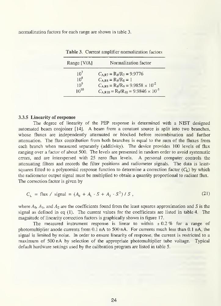
normalization factors for each range are shown in table 3.
Table 3. Current amplifier normalization factors
Range [V/A] Normalization factor
107
Ca,R7 = Rg/R? = 9.9776
108
Ca,r8 = Rg/Rg = 1
109
Ca,R9 = R8/R9 = 9.9858 x 10"2
1010
Ca.rio = Rs/Rio = 9.9846 x 10"3
3.3.5 Linearity of response
The degree of linearity of the PEP response is determined with a NIST designed
automated beam conjoiner [14]. A beam from a constant source is split into two branches,
whose fluxes are independently attenuated or blocked before recombination and further
attenuation. The flux contribution from both branches is equal to the sum of the fluxes from
each branch when measured separately (additivity). The device provides 100 levels of flux
ranging over a factor of about 500. The levels are presented in random order to avoid systematic
errors, and are interspersed with 25 zero flux levels. A personal computer controls the
attenuating filters and records the filter positions and radiometer signals. The data is least-
squares fitted to a polynomial response function to determine a correction factor (CO by which
the radiometer output signal must be multiplied to obtain a quantity proportional to radiant flux.
The correction factor is given by
CL= flux / signal = (A0
+ A, • S + A2
S2
) I S , (21)
where Aq, A\, and A2 are the coefficients found from the least squares approximation and S is the
signal as defined in eq (1). The current values for the coefficients are listed in table 4. The
magnitude of linearity correction factors is graphically shown in figure 17.
The measured instrument response is linear to within ± 0.2 % for a range of
photomultiplier anode currents from 0. 1 nA to 500 nA. For currents much less than 0. 1 nA, the
signal is limited by noise. In order to ensure linearity of response, the current is restricted to a
maximum of 500 nA by selection of the appropriate photomultiplier tube voltage. Typical
default hardware settings used by the calibration program are listed in table 5.
24
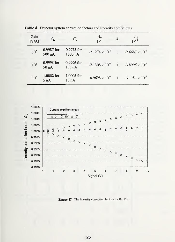
Table 4. Detector system correction factors and linearity coefficients
Gain
[V/A]
Ao
[V]A,
A 2
[V1
]
107 0.9987 for
500 nA0.9973 for
1000 nA-2.1274 x 10"8
1 -2 6687 x 10^
108 0.9998 for
50 nA0.9996 for
100 nA-2.1308 x 10"6
1 -3.8995 x 10"5
109 1.0002 for
5nA1.0003 for
10 nA-8.9698 x 10'9
1 -3.1787 x 10"5
1.0020
1.0015 1
1.0010
g 1 .0005
JO1.0000c
goQ>i_i—OO
0.9995
0.9990
& 0.9985
<a03c 0.9980
0.9975
0.9970
Current amplifier ranges
x107 O 108 A 10
9
A A A A A A A A A A A
01 23456789 10
Signal (V)
Figure 17. The linearity correction factors for the PEP.
25
Illo
I El
Osm
00
tN
©
SOSOSO00
ininm<N
<*soorn
soooOsOs©©
so00OSOs©©
SOr-t>Os
SO
OS
ao
au .2
u©
sosoSO00
>nCsl
r-<n
tsCO
On
<NSO
3 sOS pi so
OsSOOs
Xin
©X
mO
Xr~-0000CO
X«*oo
p"
f9 o
X X00©SO
Xr-sO>n©
Xr»00
Os
XOs
o
© 53
on S IT]
>n
min©inr->n
iri
IT)©mmqinr-m
o « °
u
r-oo
OsOsOs©©'
OsOvOS©©'
©©©©'
oo©©
SOr~r-Os
SOr~
OS
Os
OsOS©
OsOS©d
OsOSO©
00mooOSOS©
•53
O
© ca
-J b0> © ©
a. . .
E U4) oH 1—1
©© ©©Os
©O ©8CO
26
3.3.6 Wavelength calibration
The mean effective wavelength of the PEP is calculated for temperature from 800 °C to
3000 °C by measuring its relative spectral response in the NIST Visible/Near Infrared Spectral
Comparator Facility [15]. The collimating lens, aperture stop, optics enclosure, and PMT system
of the PEP were set up in the Spectral Comparator Facility and the relative spectral response was
measured while maintaining the same system geometry as in the RTCL. The PEP was measured
from 400 nm to 900 nm in 5 nm steps and from 630 nm to 670 nm in 0.2 nm steps. The relative
spectral response was calculated from the following equation,
SpEP (jj
S«a (X)
'w
GPEP
(23)
where /?pep(A)is the relative spectral response of the PEP in [AAV] as defined in eq (2), S?e?(X) is
the signal from the PEP in [V], Sm \(X) is the signal from the monitor detector simultaneous with
Spep(X), Sw(Jl) is the signal from the detector working standard (DWS), Sm2(X) is the signal from
the monitor detector simultaneous with Sw(X), Rw(^) is the absolute spectral response of the
DWS, Gw is the calibrated amplifier gain for the DWS in [V/A], and GPEp is the calibrated
amplifier gain for the PEP. The PEP results are relative spectral responses because the
measurement was performed in the overfill mode that resulted in a slightly different spot size.
From eq (18), the CW was determined to be 655.0 nm and the SBW was calculated to be 5.0 nmfrom eq (20) for data over the 400 nm to 900 nm range. The CW was 655.3 nm with a SBW of
4.2 nm for the 630 nm to 670 nm data. Relative to the peak value, the measured relative spectral
responsivity values decrease to about 10"4 at 5 nm from the central wavelength and to about 10"6
at 50 nm as illustrated in figure 18. Spectral radiance as defined in eq (4) is a function of a single
wavelength, X. However, the PEP has a finite bandwidth, and the PEP measures radiance as
defined by an integral form of the Wien equation,
900C]
Rk dX, (24)
400X5
exp(c2l(X T))
which could be used in the ITS-90 definition of eq (14). In the RTCL, the single wavelength
Xj T used in eq (4) is be defined as follows,
(\ 1^
27

where "kjTi
is the mean effective wavelength, L\ is the radiance of the test lamp at temperature
T\, and hi is the radiance of the WS at temperature T2 .
All of the temperature measurements are performed for a mean effective wavelength of
655.3 nm, and these corrections are calculated for the VTBB with an emissivity of 0.99. The
spectral radiance LxiX, £a, T) of the blackbody is defined by eq (5) to be a function of the
wavelength, spectral emissivity, and the temperature, while the temperature T{X, Lx, £\) is
defined by eq (6) to be a function of the wavelength, spectral emissivity, and the spectral
radiance. The following steps are performed to calculate the corrections at 900 nm for
T0 = 1073 K.
=> Calculate Lq= 1.2856 W-cm~3-sr"', where X = 655.3 nm, ex = l,andr=7b
=> Calculate T\ = 1073.53 K, where A = 655.3 nm, ex = 0.99, and L\ = L0
=> Calculate U = 68.31 W cm"3sf\ where A = 900 nm, ex = 0.99, and T=T
X
=> Calculate T2 = 1072.80 K, where X = 900 nm, Sx= 1, and Lx = U
The corrections T2 - To that are added to the radiance temperature at 655.3 nm to determine the
radiance temperatures at 900 nm and 1000 nm are given in table 6. These corrections are
equivalent to a spectral radiance correction of -0.27 % at 900 nm and -0.34 % at 1000 nm.
400 450 500 550 600 650 700 750 800 850 900
Wavelength (nm)
Figure 18. Relative spectral response of the NIST photoelectric pyrometer.
28
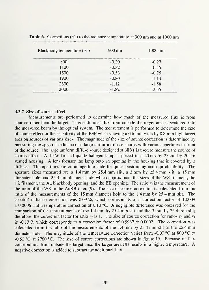
Table 6. Corrections (°C) to the radiance temperature at 900 nm and at 1000 nm
jjidCKDOQy lemperdiure ^Q00 nmyyjvj inn 1 nnn nm
800 -0.20 -0.27
1100 -0.32 -0.45
1500 -0.53 -0.75
1900 -0.80 -1.13
2300 -1.12 -1.58
3000 -1.82 -2.55
3.3.7 Size of source effect
Measurements are performed to determine how much of the measured flux is from
sources other than the target. This additional flux from outside the target area is scattered into
the measured beam by the optical system. The measurement is performed to determine the size
of source effect or the sensitivity of the PEP when viewing a 0.6 mm wide by 0.8 mm high target
area on sources of various sizes. The magnitude of the size of source correction is determined by
measuring the spectral radiance of a large uniform diffuse source with various apertures in front
of the source. The large uniform diffuse source designed at NIST is used to measure the source of
source effect. A 1 kW frosted quartz-halogen lamp is placed in a 20 cm by 23 cm by 20 cmvented housing. A lens focuses the lamp onto an opening in the housing that is covered by a
diffuser. The apertures are on an aperture slide for quick positioning and reproducibility. The
aperture sizes measured are a 1.4 mm by 25.4 mm slit, a 3 mm by 25.4 mm slit, a 15 mmdiameter hole, and 25.4 mm diameter hole which approximate the sizes of the WS filament, the
TL filament, the Au blackbody opening, and the BB opening. The ratio r\ is the measurement of
the ratio of the WS to the AuBB in eq (9). The size of source correction is calculated from the
ratio of the measurements of the 15 mm diameter hole to the 1.4 mm by 25.4 mm slit. The
spectral radiance correction was 0.09 %, which corresponds to a correction factor of 1 .0009
± 0.0006 and a temperature correction of 0.10 °C. A negligible difference was observed for the
comparison of the measurements of the 1.4 mm by 25.4 mm slit and the 3 mm by 25.4 mm slit;
therefore, the correction factor for ratio ri is 1 . The size of source correction for ratios and r$
is -0.13 % which corresponds to a correction factor of 0.9987 ± 0.0002. The correction was
calculated from the ratio of the measurements of the 1.4 mm by 25.4 mm slit to the 25.4 mmdiameter hole. The magnitude of the temperature correction varies from -0.07 °C at 800 °C to
-0.52 °C at 2700 °C. The size of source corrections are shown in figure 19. Because of flux
contributions from outside the target area, the larger area BB results in a higher temperature. Anegative correction is added to subtract the additional flux.
29

0.2
coO0)i_i_
oooo
(0
0)N(7)
0.1
0.0
500
-0.1
-0.2
O -0.3
-0.4
-0.5
-0.6
1255 °Ca Vtbb/SL20
• SL20/AuBB
H 1 1 1 1 h H h H h H H h
1000 1500 2000 2500 3000
Temperature (°C)
Figure 19. The size of source corrections for the variable temperature blackbody to the working
standard lamp comparison and the working standard lamp to the gold-point blackbody.
3.4 Radiance temperature scale uncertainties
From the laws of statistical theory, when the covariances of the independent variables are
assumed to be negligible, the propagation of standard uncertainty u{y) for a variable y,
(26)
can be defined in terms of the following sum,
u(y) = ( 07T7 dx :
1/2
(27)
where u(xf) are the standard uncertainties. The uncertainty in the WS lamp spectral radiance,
30
U 0 v-^WS )
dLws
+
dn-u{nk )
u(c2 )
OLws _Y (dL
+1=1
dX
dL
u(X) + ws
dT\
nl/2
Ail
ws"(*,)
u(TAu )
(28)
can be calculated by the root sum of squares (RSS) of the products of partial derivatives with
their respective uncertainties. This uncertainty «o(£ws) can be derived directly from the
measurement equation in eq (16) by using the propagation of standard uncertainty relationship in
eq (27). The partial derivatives are those of the spectral radiance with respect to the independent
variables in eq (16) and are listed in eqs (29) through (33). The eleven variables in the
summation of eq (28) are the following variables: eAu , c lL , n, CA,ws, CL,ws, Cs.ws, Gws, Ca,au ,
Cl,au, Cs.Au, or Gau- Since all of the measurements in the RTCL are based on the WS lamp, the
uncertainty analysis of each calibration service (tungsten ribbon filament lamps, disappearing
filament optical pyrometers, infrared thermometers) will be completed in Sections 4, 5, and 6
using the uncertainty in wo(Lws)-
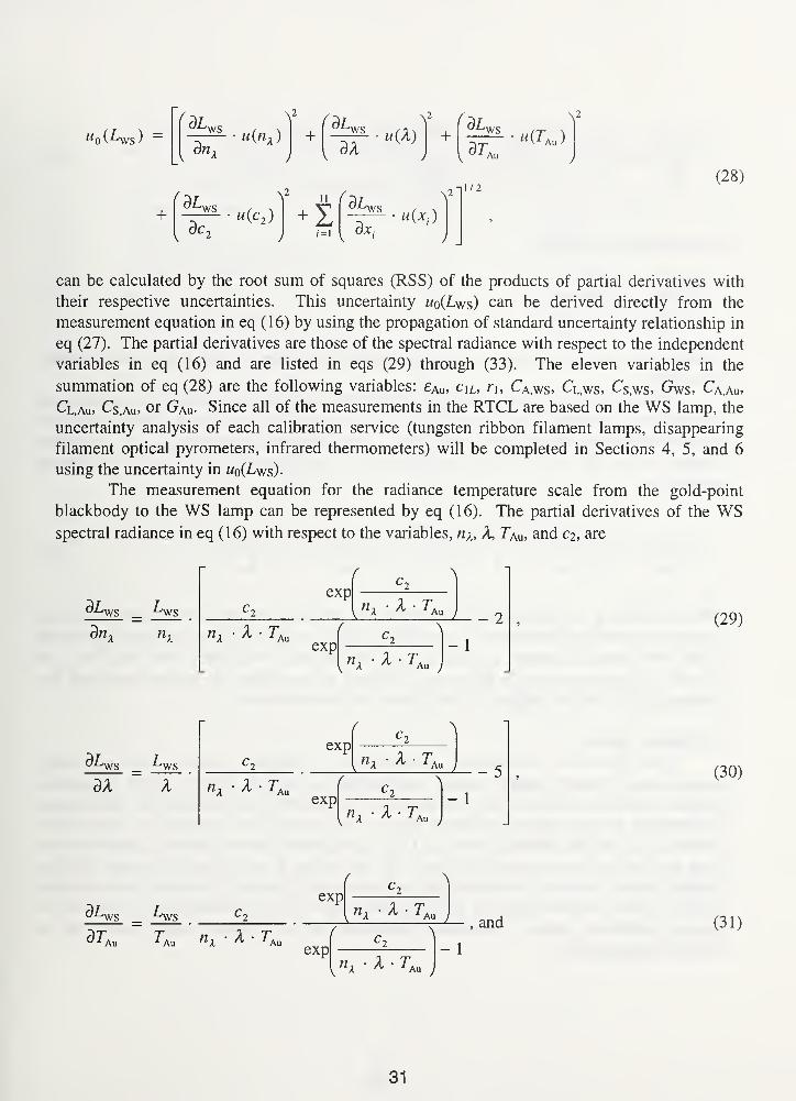
The measurement equation for the radiance temperature scale from the gold-point
blackbody to the WS lamp can be represented by eq (16). The partial derivatives of the WSspectral radiance in eq (16) with respect to the variables, ni, A, Tau, and ci, are
X T,Au
r
expX T,
exp
Au - 2
XT - 1
Au
(29)
dX X X T,Au
expX TAn
expX T,
- 1
Au
(30)
37\,
Lws
Au X TAu
expX T,Au
, and (31)
exp
v "a• 4 • TAu
- 1
31
dAys _ Ays
3c,
exp
c2
nK X- TAuexp
(32)
- 1
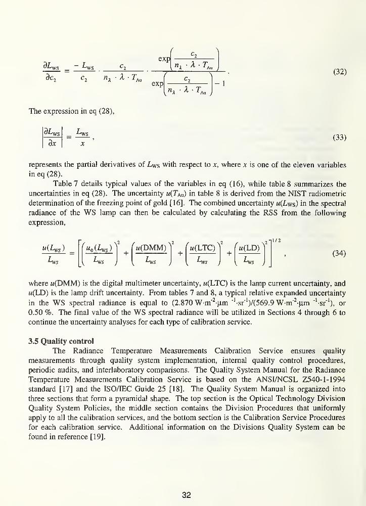
The expression in eq (28),
3jc
Avs(33)
represents the partial derivatives of Lws with respect to x, where x is one of the eleven variables
in eq (28).
Table 7 details typical values of the variables in eq (16), while table 8 summarizes the
uncertainties in eq (28). The uncertainty u(TAu) in table 8 is derived from the NIST radiometric
determination of the freezing point of gold [16]. The combined uncertainty m(Lws) in the spectral
radiance of the WS lamp can then be calculated by calculating the RSS from the following
expression,
"(Are) =Avs
^ u0(Lws )
''
Avs
+^w(LTC)^
2
h(DMM)
Avs
+Avs
+( m(LD) ^
Avs
-il/2
(34)
where «(DMM) is the digital multimeter uncertainty, w(LTC) is the lamp current uncertainty, and
m(LD) is the lamp drift uncertainty. From tables 7 and 8, a typical relative expanded uncertainty
in the WS spectral radiance is equal to (2.870W m"2 um
"1
-sr"1
)/(569.9 W-m"2-um "^sr"
1
), or
0.50 %. The final value of the WS spectral radiance will be utilized in Sections 4 through 6 to
continue the uncertainty analyses for each type of calibration service.
3.5 Quality control
The Radiance Temperature Measurements Calibration Service ensures quality
measurements through quality system implementation, internal quality control procedures,
periodic audits, and interlaboratory comparisons. The Quality System Manual for the Radiance
Temperature Measurements Calibration Service is based on the ANSIZNCSL Z540- 1-1994
standard [17] and the ISO/IEC Guide 25 [18]. The Quality System Manual is organized into
three sections that form a pyramidal shape. The top section is the Optical Technology Division
Quality System Policies, the middle section contains the Division Procedures that uniformly
apply to all the calibration services, and the bottom section is the Calibration Service Procedures
for each calibration service. Additional information on the Divisions Quality System can be
found in reference [19].
32
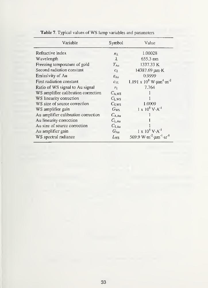
Table 7. Typical values of WS lamp variables and parameters
Variable Symbol Value
Refractive index nx 1.00028
Wavelength X 655.3 nmFreezing temperature of gold 1 An 1337.33 KSecond radiation constant Cl 14387.69 (im-K
Emissivity of Au 0.9999
First radiation constant Cm 1 191 x 108 W um4
-m"2
i 1 y 1 X W T T 1 11 111
Rntin nf sicrnal tn An c i crn si 1 1 17 764
WS amnlifier calibration correction 1
WS linearity correction Cl,ws 1
WS size of source correction Cs.ws 1.0009
WS amplifier gain Gws 1 x 10⁸ V A"
1
Au amplifier calibration correction Ca,Au 1
Au linearity correction Cl,Au 1
Au size of source correction Cs.Au 1
Au amplifier gain Gau 1 x 10⁸ V A"
1
WS spectral radiance 569.9 W-rnVrn'-sr-'
33
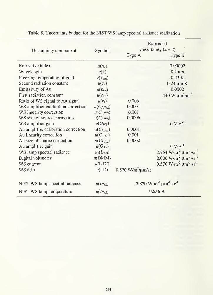
Table 8. Uncertainty budget for the NIST WS lamp spectral radiance realization
Expanded
U Ill/CI lallliy L.U1I1JJLM1CI11 O y II1UU1Uncertainty (/: = 2)
Type A Type B
Refractive index u(nx) 0.00002
Wavelength u(X) 0.2 nmFreezing temperature of gold W(Xau) 0.23 KSecond radiation constant u(c2 ) 0.24 |nm-K
Emissivity of Au u(£au) 0.0002
First radiation constant u(cm) 440 W-Lim4-m"
21 IV f T LAI 11 111
Ratio of WS signal to Au signal u(r\) 0.006
WS amplifier calibration correction m(Ca,ws) 0.0001
WS linearity correction w(Cl,ws) 0.001
WS size of source correction w(Cs,ws) 0.0006
WS amplifier gain 0 VA" 1
r\U ampilliei CallUlallUll HJIICC-11UI1 M^A.AuJ U.UUU 1
Au linearity correction «(Cl,Au) 0.001
au size or source correciion til C„ ."\ u.uuuz
Au amplifier gain m(Gau) 0 VA" 1
WS lamp spectral radiance wo(^ws) 2.754 W-nfVm^sr" 1
Digital voltmeter w(DMM) 0.000 Wm^jLim^sf 1
WS current w(LTC) 0.570 Wm^iim'sr 1
WS drift m(LD) 0.570 W/m2/|Lim/sr
NIST WS lamp spectral radiance 2.870 W m 2vim
1sr
1
NIST WS lamp temperature u(Tws) 0.536 K
34
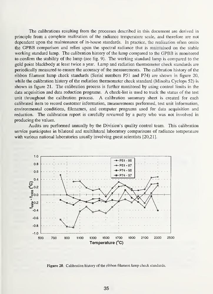
The calibrations resulting from the processes described in this document are derived in
principle from a complete realization of the radiance temperature scale, and therefore are not
dependent upon the maintenance of in-house standards. In practice, the realization often omits
the GPBB comparison and relies upon the spectral radiance that is maintained on the stable
working standard lamp. The calibration history of the lamp compared to the GPBB is monitored
to confirm the stability of the lamp (see fig. 9). The working standard lamp is compared to the
gold point blackbody at least twice a year. Lamp and radiation thermometer check standards are
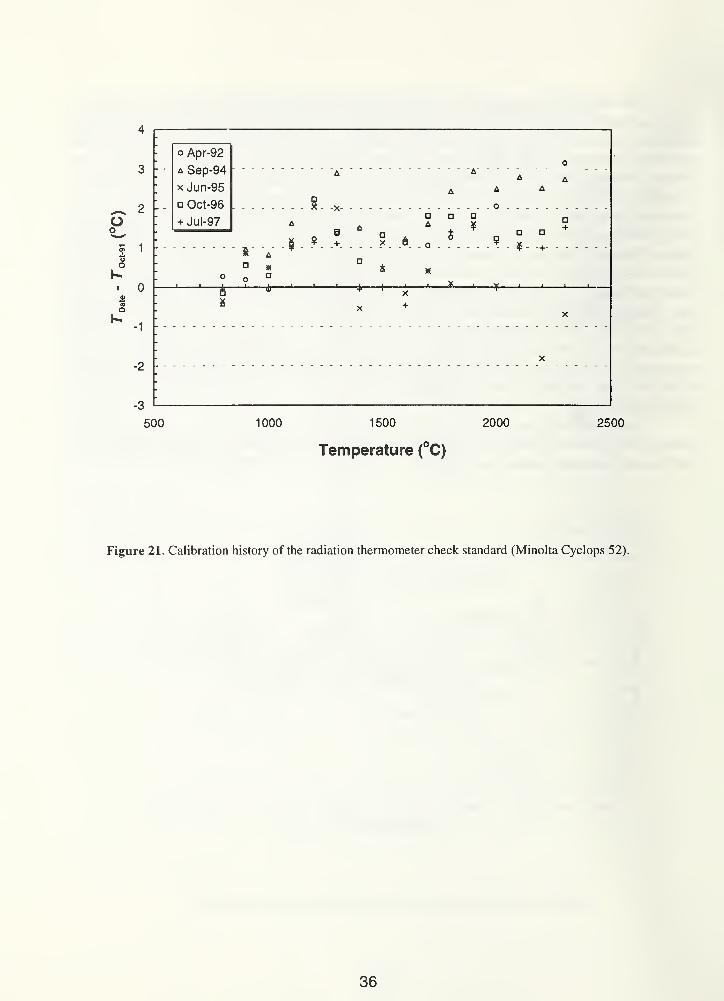
periodically measured to ensure the accuracy of the measurements. The calibration history of the
ribbon filament lamp check standards (Serial numbers P51 and P74) are shown in figure 20,
while the calibration history of the radiation thermometer check standard (Minolta Cyclops 52) is
shown in figure 2 1 . The calibration process is further monitored by using control limits in the
data acquisition and data reduction programs. A check-list is used to track the status of the test
unit throughout the calibration process. A calibration summary sheet is created for each
calibrated item to record customer information, measurements performed, test unit information,
environmental conditions, filenames, and computer programs used for data acquisition and
reduction. The calibration report is carefully reviewed by a party who was not involved in
producing the values.
Audits are performed annually by the Division's quality control team. This calibration
service participates in bilateral and multilateral laboratory comparisons of radiance temperature
with various national laboratories usually involving guest scientists [20,21].
Figure 20. Calibration history of the ribbon filament lamp check standards.
35
^ 2
Oo
? 1
oO
0sre
QK
-1
-2
500
o Apr-92
a Sep-94
x Jun-95
Oct-96
+ Jul-97
1000 1500 2000
Temperature (°C)
2500
Figure 21. Calibration history of the radiation thermometer check standard (Minolta Cyclops 52).
36
4. Tungsten Ribbon Filament Lamp Calibrations
4.1 Lamp preparation
Tungsten ribbon filament lamps are calibrated by NIST for the temperature range 800 °C
to 2300 °C in terms of the 1990 NIST Radiance Temperature Scale by spectral comparison to a
standard temperature lamp calibrated at 655.3 nm. New lamps are inspected for filament
continuity, envelope and window clarity, and filament flatness and centering. A digital
multimeter is used to check the filament continuity. The envelope or window is checked for
defects and striations in the optical path. The filament is checked to determine that it is flat,
parallel to the envelope walls, and within 2 mm of being centered in the envelope or window.
The lamps are cleaned with water and laboratory glassware detergent.
Test lamps (TL) are operated base down on direct current with the center contact (longer
filament support for a bipost base lamp) at the positive potential. The test lamps are tested for air
leaks by turning the lamp on, then off, and then on again after 15 min. If air has leaked into the
lamp envelope because of bad or broken seals, then the lamp will fail when it is turned on.
Lamps that pass the leak test are annealed to improve lamp stability. New gas lamps are
annealed at a radiance temperature of 2350 °C at 655.3 nm for 2 h on direct current and vacuum
lamps are annealed at 1450 °C for about 14 h. The gas lamps are aged for an additional 50 h at
2300 °C.
The lamp orientation chosen for the calibration of a new lamp minimizes the variation in
lamp output while maintaining the optical axis of the measuring instrument approximately
normal to the lamp filament. This orientation is determined with the lamp operating at
approximately 1700 °C for a gas lamp, or 1200 °C for a vacuum lamp. An arrow is etched onto
the rear surface of the lamp envelope to allow reproducible alignment of this orientation. The
alignment is performed with the lamp operating base down, the filament vertical, and the optical
axis of the PEP passing through the lamp envelope and intersecting the center of the filament at
the height of the notch. The sides of the target area, area 0.6 mm wide by 0.8 mm high, are
approximately parallel to the sides of the lamp filament. The center of the target area is located
at the intersection of two orthogonal lines on the filament surface. One line bisects the filament
lengthwise, and the other passes through the point centered at the mouth of the notch. The lamp
is positioned so that the etched arrow on the lamp envelope is to the rear, as viewed from the
PEP. The center of the target area is viewed along the horizontal optical axis of the PEP. Aplumb line is used to make the notch side of the filament vertical. The image of the lamp
filament is focused onto the field stop of the PEP to within ±2.5 mm. The lamp is then
successively rotated about the horizontal and vertical centerlines through the target area until the
tip of the arrowhead is centered at the mouth of the notch.
4.2 Lamp calibration
The values of radiance temperature apply when the lamp has been aligned to a specified
orientation while operating at a designated radiance temperature and after the lamp has reached
thermal stability at each specified operating current. The WS and TL are aligned as described in
Section 4.1 at one temperature. At all other temperatures, the TL is translated vertically and/or
horizontally so that the target area viewed by the PEP is always centered on the lamp filament at
the height of the notch. No additional rotational alignments are performed
37
The initial lamp current that corresponds to 1700 °C is selected from previous data for the
lamp type. The TL is turned on and set to approximately 1700 °C and aligned after 30 min. The
spectral radiance ratio of the TL to the WS, ri, is calculated, the WS signal, Sws2, is measured,
and the TL signal, Stl, tnat corresponds tol700 °C is calculated. The lamp current is adjusted
until the measured signal is equal to Stl- After waiting 10 min, the final alignment of the TL and
the WS is performed and the TL is spectrally compared to the WS to determine its radiance
temperature. The spectral radiance ratio of the TL to the WS is measured three times by
alternately translating the WS and the TL to the PEP. If the percent standard deviation of the
ratio is less then the control limit, then the next calibration point is measured; otherwise, the
point is repeated. The control limits are equal to the relative standard uncertainty {k = 1 ) of the
ratio and were determined from previous calibration data. The control limits are the expected
uncertainties for the spectral radiance ratio measurement. Next, the TL is aligned and measured
at 2300 °C after waiting 20 min. The additional calibration temperatures are aligned and
measured in decreasing order after waiting 10 min. A typical calibration interval is 100 °C. The
following temperatures are repeated at the previously determined lamp currents to estimate the
lamps stability: 1700 °C, 2300 °C, 1900 °C, 1500 °C, 1 100 °C, and 800 °C. The following data
is stored in a computer file: nominal temperature, measured temperature, lamp current, and
spectral radiance ratio. See the "Ribbon Filament Lamp Calibration Procedure" in Appendix Dfor a more details on lamp calibrations in the RTLC.
4.3 Lamp data analysis
The repeated calibration temperatures are averaged and the standard error of the mean is
calculated and compared to the absolute control limits. These results are used to determine the
expanded uncertainties listed in the calibration report.
Calibration data is reported at the nominal temperatures 800 °C, 900 °C, 1000 °C, ...
2300 °C. One method to determine the nominal temperatures is to measure it directly. Through
an iterative process, the TL is repeatedly measured and the lamp current is adjusted until the
nominal temperature is actually measured. However, the RTCL calculates the lamp current that
corresponds to the nominal temperature from measurements of the measured temperature (rm)
near the nominal temperature (rn).
For a small AT, where AT - Tn - Tm , the small change in lamp current is approximated by
the slope of the tangent at T and given by
dI(T) AIr
I(T + AT) - I(T) ....— = hm —— = lim —• pjj
di Ar->o AT Ar->o AT
This limit simplifies to a working equation of the form
I(T + AT) = I(T) + AT, (36)
dT
where I(T) is the measured lamp current /m at Tm and I(T + AT) is the measured lamp current 7(
The derivative dl/dT can be approximated by AI/AT, which can be modeled as
38
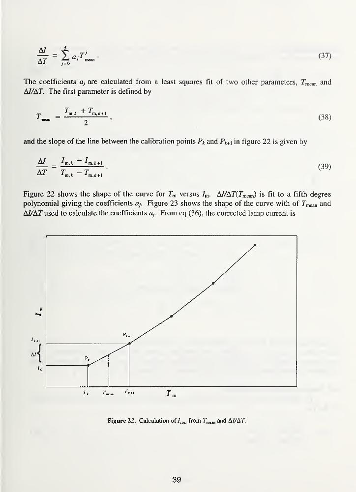
AT % a >(37)
The coefficients a, are calculated from a least squares fit of two other parameters, Tmem and
AI/AT. The first parameter is defined by
TmeanT + T
(38)
and the slope of the line between the calibration points Pk and Pk+ \ in figure 22 is given by
A/ ^m,*— Im,k + l
(39)
Figure 22 shows the shape of the curve for Tm versus /m . AI/AT(Tmean) is fit to a fifth degree
polynomial giving the coefficients q. Figure 23 shows the shape of the curve with of Tmean and
AI/AT used to calculate the coefficients a7
. From eq (36), the corrected lamp current is
Figure 22. Calculation of Icori from T^an and A//Ar.
39

determined to be
/corr = /m + (r„ " Tm) (40)
3
Figure 23. Graph of 7mean and M/AT.
A least squares fit of the entire calibration data sets finds the best curve for the data set but not
necessarily for each data point. This method ensures that the direction of the correction is right
and has been verified by comparison to the iterative method. Sample data can be found in the
"Ribbon Filament Lamp Data Reduction Procedure" in Appendix D.
4.4 Lamp calibration uncertainty
To calibrate test lamps (TL), the ratio {ri) of the spectral radiance of the WS lamp to that
of the TL,
r2 = Lx(Tjl) = Jk-, (41)
(^WS2 ) ^WS2
40

is first measured. Taking into account the correction factors for the signals, the overall
measurement equation for the 1990 NIST Scale of Radiance Temperature for calibration of the
TL temperature is
T =
X In 1 +'A,TL (CA • CL
• Cs G)ws
^WS2 r2 (Ca CL Cs G)
TL
(42)
In a manner similar to eq (28), the uncertainty in the spectral radiance of the WS can be
represented by the RSS of products of partial derivatives,
W0 (-^TL )
r drTL , !\ far,
dn.u(nx) + TL
dXu(X) + TL
u(c2 )
12 ( ?>T ^nl/2
(43)
where x\ is one of the variables: £tl, c [L ,LWs, r2 , Ca.ws, Cl,ws, Cs.ws, Gws, Ca.tl, Cl.tl, Cs,tl, or
Gtl- The partial derivatives of 7tl with respect to nx, X, and c2 are
ar,TL TL
(CA •CL • Q • G )WS
' A,TL C1Z. (CA ' CL ' CS ' G )TL
"I * ^WS2
A • 7;
expTL l
A " ^ ' ^TL ;
(44)
ar,TL
aA
TTL "A.TL
X5 LWS2
(Ca " Cl ' Cs • G)
(c, TL
n x X TTLexp
- 1
X ZTL
, and (45)
TL TL(46)
41
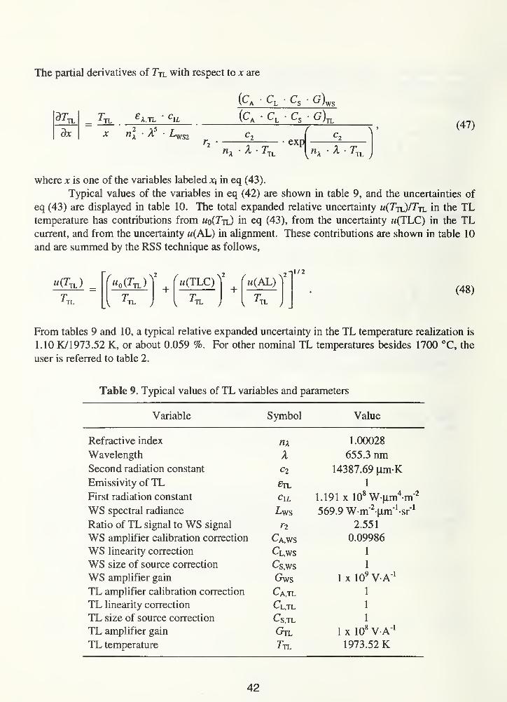
The partial derivatives of 7tl with respect to x are
TL TL
dx
A.TL
A • Z/^yS2
OS.
(c,
"a * TL
Cs• G).
exp
(47)
A • 7;TL
where x is one of the variables labeled xxin eq (43).
Typical values of the variables in eq (42) are shown in table 9, and the uncertainties of
eq (43) are displayed in table 10. The total expanded relative uncertainty m(7tl)/7tl in the TLtemperature has contributions from wo(Ttl) in eq (43), from the uncertainty m(TLC) in the TLcurrent, and from the uncertainty m(AL) in alignment. These contributions are shown in table 10
and are summed by the RSS technique as follows,
u{TT.)
TL
M0 (^TL )
TL
+^m(TLC) ^
TL
r u(AL) ^-11/2
TL
(48)
From tables 9 and 10, a typical relative expanded uncertainty in the TL temperature realization is
1.10 K/1973.52 K, or about 0.059 %. For other nominal TL temperatures besides 1700 °C, the
user is referred to table 2.
Table 9. Typical values of TL variables and parameters
Variable Symbol Value
Refractive index 1.00028
Wavelength A 655.3 nmSecond radiation constant C2 14387.69 nm-KEmissivity of TL £tl 1
First radiation constant C\L 1.191 x 10⁸ W-nm4
-m"2
WS spectral radiance Ly/S 569.9 Wm'2M.m
1sr
1
Ratio of TL signal to WS signal ri 2.551
WS amplifier calibration correction Ca.ws 0.09986
WS linearity correction Cl,ws 1
WS size of source correction Csy/s 1
WS amplifier gain Gws 1 x 10⁹ V A"
1
TL amplifier calibration correction Ca.tl 1
TL linearity correction Cl,tl 1
TL size of source correction Cs,TL 1
TL amplifier gain Gtl 1 x 10⁸ V A"
1
TL temperature 1973.52 K
42
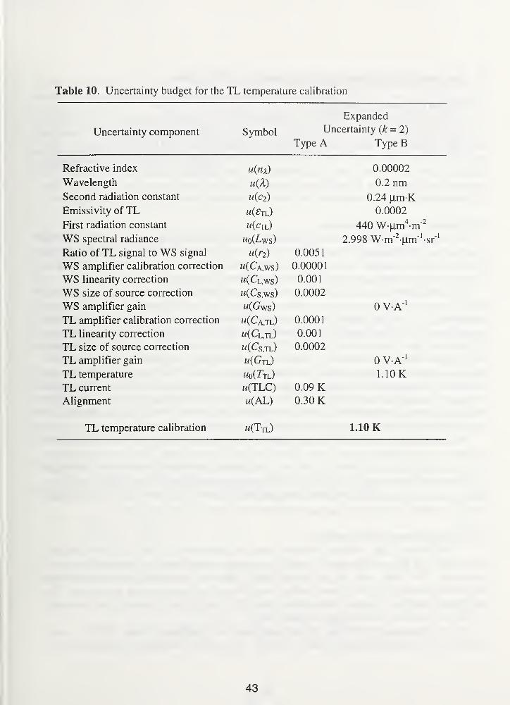
Table 10. Uncertainty budget for the TL temperature calibration
Expanded
Uncertainty component Symbol Uncertainty (k = 2)
Type A Type B
Refractive index u(nx) 0.00002
Wavelength 0.2 nmSecond radiation constant u(ci) 0 24 um-K
Emissivity of TL u(Fti ^ 0.0002
First radiation constant uiCu ) 440 W-um4m"
21 r\J T T LV1 11 111
Z.yyo W-ITl \lu\ -ST
Ratio of TL signal to WS signal u(r2 ) 0.0051
WS amplifier calibration correction w(Ca,ws) 0.00001
WS linearity correction w(Cl,ws) 0.001
WS size of source correction "(Cs.ws) 0.0002
WS amplifier gain w(Gws) 0 V-A"1
TL amplifier calibration correction u(Cajl) 0.0001
TL linearity correction w(Cl,tl) 0.001
TL size of source correction w(Cs ,tl) 0.0002
TL amplifier gain w(Gtl) 0 V-A"1
TL temperature «o(Ttl) 1.10 KTL current w(TLC) 0.09 KAlignment u(AL) 0.30 K
TL temperature calibration "(Ttl) 1.10 K
43

5. Disappearing filament optical pyrometer calibrations
5.1 Optical pyrometer preparation
Disappearing filament optical pyrometers (DFP) are calibrated from 800 °G to 4200 °C
by comparison to the VTBB. When the test unit arrives, the batteries are checked, the objective
lens and eyepiece are cleaned, and the eyepiece is focused onto the DFP lamp filament. The
lamp is checked to ensure that it is operating and that matching is possible. If an operating
manual is not on file, then one is requested from the customer because test pyrometers are
operated according to the manufacturer's instructions unless other instructions are given. The
pyrometers and associated electronics are initialized according to manufacturer's specifications.
5.2 Optical pyrometer calibration
The DFP is aligned onto the geometric center of the VTBB opening. The DFP is
measured at an appropriate distance from the front surface of the objective lens holder to the
blackbody cavity partition and is focussed on the center of the partition. After the VTBB is
turned on, the pyrometer centering is checked and adjusted as necessary.
For the 800 °C to 2700 °C temperature range, the PEP is used to spectrally compare the
VTBB to the WS to determine the radiance temperature of the blackbody at each calibration
temperature. The VTBB and the WS are compared three times and the mean is used. Once the
temperature of the blackbody has been determined, the test DFP lamp filament is matched in
brightness to that of the blackbody, and the DFP lamp current is measured using a standard resistor
and a digital voltmeter. The matching is performed from bright to disappearance and from dark to
disappearance twice and the mean of the four readings is used. The indicated temperature is
recorded for pyrometers with either a temperature scale or a digital panel indicator. The output
voltage is measured for pyrometers with internal current measuring resistors. The DFPmeasurements are not bracketed by VTBB measurements because the VTBB has been shown to be
stable to within ± 0. 1 °C during the time required to complete the measurements.
For temperatures above 2700 °C, the method used to extrapolate the calibration to 4200 °C
involves measuring temperatures below 2700 °C on two or more ranges. For a three-range DFPwith a low range (L) from 1 100 °C to 1700 °C, a medium range (M) from 1700 °C to 2800 °C, and
a high range (H) from 2900 °C to 4200 °C, the following measurements are performed. The DFPlamp currents are measured for VTBB temperatures from 1 100 °C to 1700 °C on the L range, from
1600 °C to 2700 °C on the M range, and from 1700 °C to 2700 °C on the H range.
5.3 Optical pyrometer data analysis
The various data reduction methods used are determined by how the DFP indicates
temperature. In all cases, the data is sorted by range and averaged and the standard deviation is
calculated. For DFPs with ranges below 2700 °C, the data is analyzed and the blackbody
temperature versus the scale or panel reading, output current, or output voltage is reported. The
pyrometer correction, blackbody temperature minus DFP reading, that is added to the pyrometer
reading is reported for scale and panel indicator DFPs.
For the three-range DFP case when temperatures are determined above 2700 °C, more
calculations are required before the data is reported. The current measurement averages are fit to
44

the curve I(T) = ao + a\T + a^T + ayT calculating a least squares approximation for each DFPrange. For the L range the blackbody temperatures are calculated at the nominal temperatures
1100°C, 1200 °C, 1700 °C and reported versus the pyrometer lamp currents. For the
M range, the blackbody temperatures are calculated at the nominal temperatures 1700 °C,
1800 °C, 2700 °C and reported versus the pyrometer lamp currents. The 2800 °C calibration
point is determined in two steps. The first step is to calculate AM , the "A" value [22] for the Mrange, which is defined be the relationship,
A = - -±- = — 4n T , (44)* APP * BB C
2
where TAPP is the apparent temperature [K], rBB is the blackbody temperature [K], X is the filter
transmittance, and A is the "A" value [K~ ]. From eq (44), it becomes apparent that In t must be
approximately equal to MX in order for A to be constant. Typically, the value of A is on the order
of 173X10"6K"
1
. rBB , is determined during the M range measurements. TAPP is the temperature on
the L range that corresponds to the current measured on the M range which is determined through
iteration of the L range function I(t). The second step is to use the "A" value to calculate the
pyrometer lamp current that corresponds to the extrapolated blackbody temperature at 2800 °C.
Use eq (44) to calculate TAPP2 when TBm = 3073.15 K and A =AM . Next calculate the pyrometer
lamp current using the L range function /(?)•
This procedure is repeated to determine the extrapolated blackbody temperatures for the Hrange. The H range "A-value", AH , is determined where TAPP is the temperature on the L range
that corresponds to the current measured on the H range and TBB is the blackbody temperature
during the H range measurements. AH is then used to calculate the apparent temperature TAPP2 for
each extrapolated blackbody temperature from 2900 °C to 4200 °C. The pyrometer lamp
currents are calculated from the L range function I(t). The extrapolated blackbody temperatures
for the M and H ranges are reported versus the pyrometer lamp currents.
5.4 Optical pyrometer calibration uncertainty
To calibrate disappearing filament optical pyrometers (DFP), the ratio (r?) of the spectral
radiance of the WS lamp to that of the variable-temperature blackbody (BB),
Lx (Tbb ) _ ^BB(45)
is first measured to determine the radiance temperature of the BB, T(A,La,bb), at each
disappearing filament optical pyrometer temperature by the equation,
T =1 BB
A • In 1 +A,BB
^ ' AvS3 ' h (^A " S ^ObB _
(46)
45
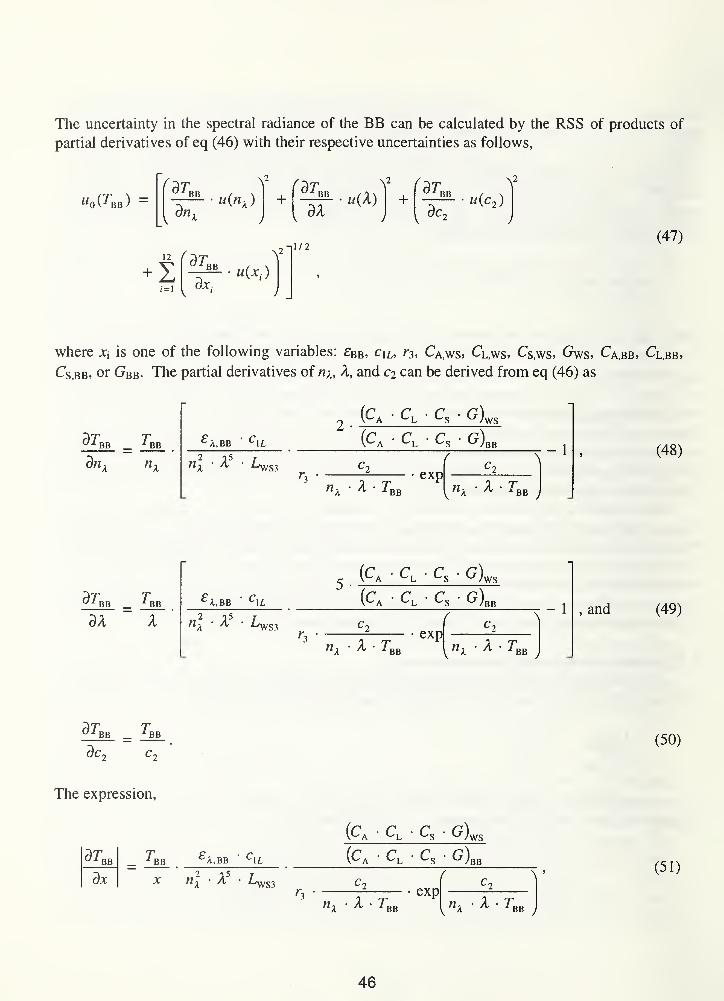
The uncertainty in the spectral radiance of the BB can be calculated by the RSS of products of
partial derivatives of eq (46) with their respective uncertainties as follows,
M0 \ BB )—
ar,BBu(n x ) +
far,
12 ( r)T
v
-11/2
-52- • U(X)dX
V far,BB
,ac
2
«(c2 )
(47)
1=1
BB
dx.
u{xi )
where xj is one of the following variables: £Bb, c\L,r3 , CA,ws, Cl,ws, Cs,ws, Gws, Ca>bb, Cl,bb,
Cs,bb, or Gbb- The partial derivatives of nx, X, and ci can be derived from eq (46) as
ar,BB
dn.
BB
2 •
£ A,BB ' C\L
(^A ' ^)\VS
(CA • CL Cs• G)BB -
1
S3
X • Zexp
BBvnx 4 • rBB
(48)
ar,BB
aA
BB ^A.BB ' C1L
x • X £ws3
(CA ' CL ' Q ' G)
(CA • CL ' Q ' G )
«A • ^ • ^BB
exp
V «A
- 1 , and
A • r,BB
(49)
ar,BB BB(50)
The expression,
ar,BB
a*
BB£ A,BB " CIL
n x XS3
(CA • CL• Cs
• G)ws
^)bb
nk " ^ " ^bb
exp
v «a• ^ • rBB
y
(51)
46
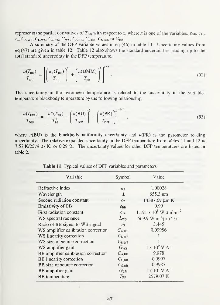
represents the partial derivatives of TeB with respect to x, where x is one of the variables, £B b, C\l,
r-i, C\,ws> ^l,ws, Cs.ws, G\vs, Ca.bb, Cl,bb, ^s.bb, or ^bb-
A summary of the DFP variable values in eq (46) in table 1 1. Uncertainty values from
eq (47) are given in table 12. Table 12 also shows the standard uncertainties leading up to the
total standard uncertainty in the DFP temperature,
w(^bb )
BB
( U0 (^BB )
BB
+w(DMM)
BB
1/2
(52)
The uncertainty in the pyrometer temperature is related to the uncertainty in the variable-
temperature blackbody temperature by the following relationship,
^(*DFP )
DFP
u\Tm )+ {
n(BU) ^ + fm(PR)
1 BB ' DFPj
+1 DFP J
1/2
(53)
where w(BU) is the blackbody uniformity uncertainty and u(PR) is the pyrometer reading
uncertainty. The relative expanded uncertainty in the DFP temperature from tables 11 and 12 is
7.57 K/2579.07 K, or 0.29 %. The uncertainty values for other DFP temperatures are listed in
table 2.
Table 11. Typical values of DFP variables and parameters
Variable Symbol Value
Refractive index nx 1.00028
Wavelength X 655.3 nmSecond radiation constant 14387.69 fim-K
Emissivity of BB £bb 0.99
First radiation constant C\L 1.191 x 10⁸ W uxn
4 mWS spectral radiance 569.9 W-m'Vm^sfRatio of BB signal to WS signal 3.445
WS amplifier calibration correction Ca,ws 0.09986
WS linearity correction Cl.ws 1
WS size of source correction Cs,ws 1
WS amplifier gain Gws 1 x 10⁹ V A"
1
BB amplifier calibration correction Ca.bb 9.978
BB linearity correction Cl,bb 0.9997
BB size of source correction Cs,BB 0.9987
BB amplifier gain Gbb 1 x 10⁷ V A"
1
BB temperature 7bb 2579.07 K
47

Table 12. Uncertainty budget for the DFP pyrometer temperature calibration
Expanded
Uncertainty factor Symbol Uncertainty (k = 2)
Type A Type B
lVvl 1 CWs Li V K/ 1 J lUvA 0 00002
w aveiengin U{A) u.z nmoecona raaidiion constant U{C2) U.Z4 (xm-K
umissiviiy or r>r> w(£bb) u.uuuz
First radiation constant U(C\i) 440 W-pxn mWS spectral radiance «(Lws) 2.998 W m \im -sr
Ratio of BB signal to WS signal 0.00682
WS amplifier calibration correction w(Ca,ws) 0.00001
WS linearitv correction 0.001
WS size of source correction «(Cs,ws) 0.0002
WS amplifier gain w(Gws) 0 V-A"1
BB amplifier calibration correction w(Ca,bb) 0.001
BB linearity correction w(Cl,bb) 0.001
BB size of source correction "(Cs.bb) 0.0002
BB amplifier gain w(Gbb) 0 VA" 1
Digital voltmeter m(DMM) OKBB temperature "(Xbb) 2.34 KBlackbody uniformity k(BU) 0.20 KDFP reading m(PR) 7.20 K
DFP temperature calibration w(Tdfp) 7.57 K
48
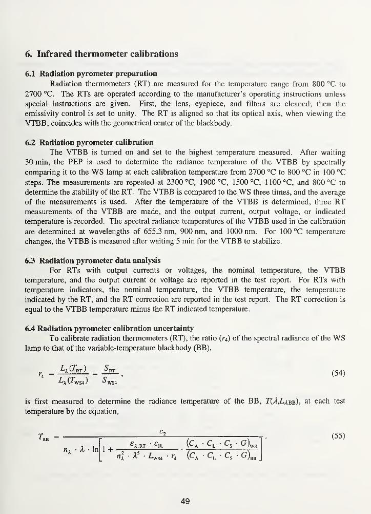
6. Infrared thermometer calibrations
6.1 Radiation pyrometer preparation
Radiation thermometers (RT) are measured for the temperature range from 800 °C to
2700 °C. The RTs are operated according to the manufacturer's operating instructions unless
special instructions are given. First, the lens, eyepiece, and filters are cleaned; then the
emissivity control is set to unity. The RT is aligned so that its optical axis, when viewing the
VTBB, coincides with the geometrical center of the blackbody.
6.2 Radiation pyrometer calibration
The VTBB is turned on and set to the highest temperature measured. After waiting
30 min, the PEP is used to determine the radiance temperature of the VTBB by spectrally
comparing it to the WS lamp at each calibration temperature from 2700 °C to 800 °C in 100 °C
steps. The measurements are repeated at 2300 °C, 1900 °C, 1500 °C, 1100°C, and 800 °C to
determine the stability of the RT. The VTBB is compared to the WS three times, and the average
of the measurements is used. After the temperature of the VTBB is determined, three RTmeasurements of the VTBB are made, and the output current, output voltage, or indicated
temperature is recorded. The spectral radiance temperatures of the VTBB used in the calibration
are determined at wavelengths of 655.3 nm, 900 nm, and 1000 nm. For 100 °C temperature
changes, the VTBB is measured after waiting 5 min for the VTBB to stabilize.
6.3 Radiation pyrometer data analysis
For RTs with output currents or voltages, the nominal temperature, the VTBBtemperature, and the output current or voltage are reported in the test report. For RTs with
temperature indicators, the nominal temperature, the VTBB temperature, the temperature
indicated by the RT, and the RT correction are reported in the test report. The RT correction is
equal to the VTBB temperature minus the RT indicated temperature.
6.4 Radiation pyrometer calibration uncertainty
To calibrate radiation thermometers (RT), the ratio (r^) of the spectral radiance of the WSlamp to that of the variable-temperature blackbody (BB),
is first measured to determine the radiance temperature of the BB, T(A,La,bb), at each test
temperature by the equation,
'A Cj^RT
)
_ *^RT(54)
(^A ' ^)\VS
(^a CL ' Cs g)bb
(55)£ 1L
nx• X • In 1 +
S4
49
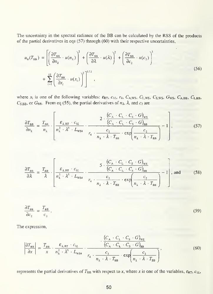
The uncertainty in the spectral radiance of the BB can be calculated by the RSS of the products
of the partial derivatives in eqs (57) through (60) with their respective uncertainties,
W0 (^~BB )—
r *Tm . ^ farnn _Y far,u{n x ) + BB
12
+ 1OX;
\
-|172
dXu(X) +
\2
BB
,5c
2
u(c2 )
(56)
where *j is one of the following variables: £RT , clL, r4 , CA,ws, CL,ws, Cs,ws, Gws, Ca.bb, Cl,bb,
Cs.bb, or Gbb- From eq (55), the partial derivatives of n%, A, and ci are
BB
dn.
BB
2 15AVS4
WS
(CA CL Cs G)BB
• exp
BB nX * ^ • ^BB
(57)
ar,BB
aA
BB
A5•
S4
(c, ' ^S G)WS
(CA • CL• Cs
• G) BB
nX • 4 • ^BB
• expXT,BB J
, and (58)
ar,BB BB(59)
The expression,
ar,BB
a*
BB ' A,RT C1L
• A • LWS4
(CA • CL . Cs. G)WS
(cA • cL• cs
• g)BB
nx & rBBexp
nx • h * ^bb ;
(60)
represents the partial derivatives of Tbb with respect to jc, where x is one of the variables, £rt, c\l,
50
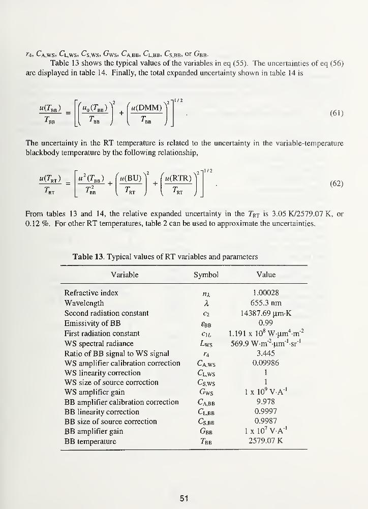
f4, Ca.ws. Cl,ws 5 Cs.ws. Gws, C\,bb, Cl,bb, Cs.bb, or Gbb-
Table 13 shows the typical values of the variables in eq (55). The uncertainties of eq (56)
are displayed in table 14. Finally, the total expanded uncertainty shown in table 14 is
"(Tbb)
BB
( M0 (-^BB )V (
+BB
«(DMM)-il/2
BB
(61)
The uncertainty in the RT temperature is related to the uncertainty in the variable-temperature
blackbody temperature by the following relationship,
u(TRT )
RT
" <Tbb) 'm(BU)^
BB RT
(w(RTR) ^
RT
1/2
(62)
From tables 13 and 14, the relative expanded uncertainty in the 7Vr is 3.05 K/2579.07 K, or
0.12 %. For other RT temperatures, table 2 can be used to approximate the uncertainties.
Table 13. Typical values of RT variables and parameters
Variable Symbol Value
Refractive index n\ 1.00028
Wavelength X 655.3 nmSecond radiation constant Cl 14387.69 u.m-K
Emissivity of BB £bb 0.99
First radiation constant 1.191 x 10⁸ W |um
4m"
2
WS spectral radiance 569.9 W-rnVm^sr" 1
Ratio of BB signal to WS signal 3.445
WS amplifier calibration correction Ca.ws 0.09986
WS linearity correction Cl,ws 1
WS size of source correction Cs.ws 1
WS amplifier gain 1 x 10⁹V-A"
1
BB amplifier calibration correction C\,bb 9.978
BB linearity correction Cl,bb 0.9997
BB size of source correction Cs,BB 0.9987
BB amplifier gain Gbb 1 x 10⁷V-A"
1
BB temperature Tbb 2579.07 K
51
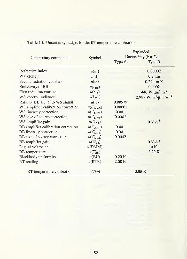
Table 14. Uncertainty budget for the RT temperature calibration
Expanded
Uncertainty component Symbol Uncertainty (k = 2)
Type A Type B
Refractive index u(nx) 0.00002
Wavelength 0.2 nmSecond radiation constant u{c2) 0.24 |0,m KEmissivity of BB "(£bb) 0.0002
First radiation constant u(c lL) 440 W-jxm4-m"
2
WS snprtral raHiancp u( Ta\/q\ 9 QQR W.m'2.iim'Ur'i.77o vv in ixiii MRatio of BB signal to WS signal u(r4 ) 0.00579
WS amplifier calibration correction m(Ca,ws) 0.00001
WS linearity correction w(Cl,ws) 0.001
WS size of source correction w(Cs,ws) 0.0002
WS amplifier gain w(Gws) 0 V A"1
BB amplifier calibration correction m(Ca,bb) 0.001
BB linearity correction w(Cl.bb) 0.001
BB size of source correction "(Cs,bb) 0.0002
BB amplifier gain m(Gbb) 0 VA" 1
Digital voltmeter w(DMM) OKBB temperature w(Tbb) 2.29 KBlackbody uniformity w(BU) 0.20 KRT reading w(RTR) 2.00 K
RT temperature calibration w(Trt) 3.05 K
52
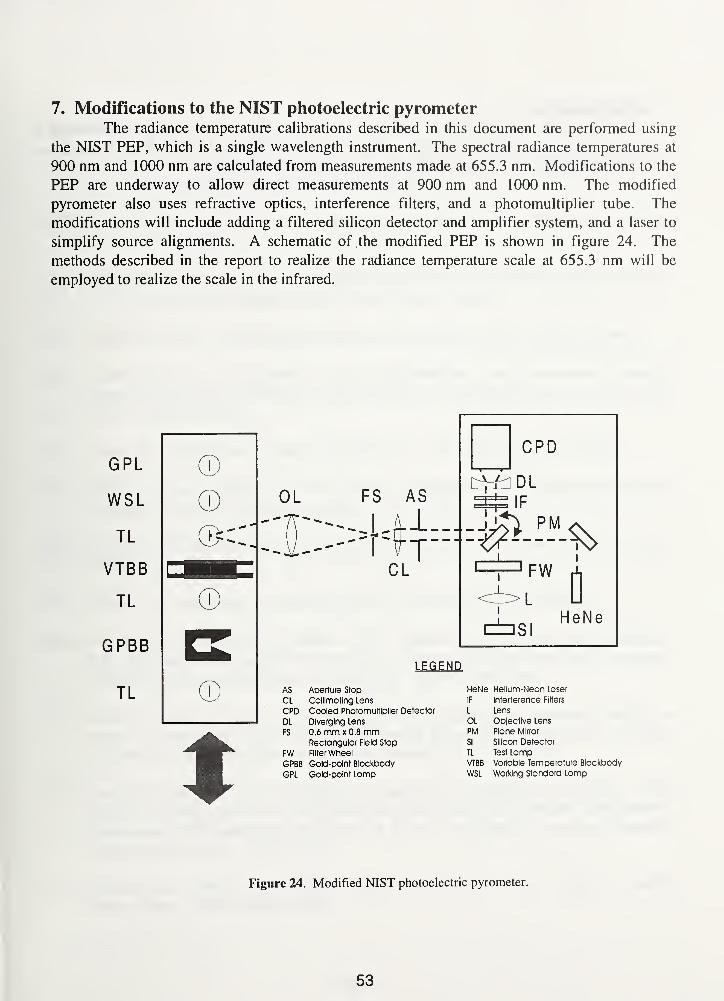
7. Modifications to the NIST photoelectric pyrometerThe radiance temperature calibrations described in this document are performed using
the NIST PEP, which is a single wavelength instrument. The spectral radiance temperatures at
900 nm and 1000 nm are calculated from measurements made at 655.3 nm. Modifications to the
PEP are underway to allow direct measurements at 900 nm and 1000 nm. The modified
pyrometer also uses refractive optics, interference filters, and a photomultiplier tube. The
modifications will include adding a filtered silicon detector and amplifier system, and a laser to
simplify source alignments. A schematic of the modified PEP is shown in figure 24. The
methods described in the report to realize the radiance temperature scale at 655.3 nm will be
employed to realize the scale in the infrared.
OL
ni I
A/.
LEGEND
AS Aperture Stop
CL Colllmating Lens
CPD Cooled Photomultiplier Detector
DL Diverging Lens
FS 0.6 mm x 0.8 mmRectangular Field Stop
FW Filter Wheel
GPBB Gold-point Blackbody
GPL Gold-point Lamp
HeNe Helium-Neon Laser
IF Interference Filters
L Lens
OL Ob|ectlve Lens
PM Plane Mirror
SI Silicon Detector
TL Test LampVTBB Variable Temperature Blackbody
WSL Working Standard Lamp
Figure 24. Modified NIST photoelectric pyrometer.
53
Acknowledgments
The authors would like to thank Robert D. Saunders for his technical assistance in
reading the manuscript and his constant encouragement. They also like to thank Frank Lovas,
Dean Ripple, and Chris Kuyatt for useful suggestions and comments.
54
References
[I] Mielenz, K.D., Saunders, R.D., Parr, A.C., and Hsia, J. J., "The 1990 NIST Scales of
Thermal Radiometry," J. Res. NIST, 95, 621 (1990).
[2] Preston-Thomas, H., "The International Temperature Scale of 1990 (ITS-90)," Metrologia,
27, 3-10, 107(1990).
[3] Taylor, B.N., and Kuyatt, C.E., "Guidelines for Evaluating and Expressing the Uncertainty
of NIST Measurement Results," NIST TN 1297 (2nd ed., 1994).
[4] Simmons, J.D. Ed., "NIST Calibration Services Users Guide," NIST SP 250, 69 (1991).
[5] Kostkowski, H.J., and Nicodemus, F.E., "An Introduction to the Measurement Equation,
Chapter 5 of Self-Study Manual on Optical Radiation Measurements: Part I - Concepts,"
NBSTN 910-2, 58(1978).
[6] Planck, M., "Distribution of Energy in the Spectrum," Ann. Phys., 4, 3, 553 (1901).
[7] Cohen, E.R. and Taylor, B.N., "The 1986 Adjustment of the Fundamental Physical
Constants," Review ofModern Physics, 59, 4, 1 121 (1987).
[8] Lide, D.R., "CRC Handbook of Chemistry and Physics," CRC Press, 67th ed., E-373
(1986-1987).
[9] Quinn, T.J., "Temperature," Academic Press Inc., San Diego, CA, 380 (1990).
[10] Saunders, R.D., Gibson, C.E., Mielenz, K.D., Sapritsky, V.I., Sudarev, KA., Khlevnoy,
B.B., Mekhontsev, S.N, and Harchenko, G.D. , "Results of a NIST/VNIIOFI Comparison
of Spectral-Radiance Measurements," Metrologia, 32, 449 (1995/1996).
[II] Quinn, T.J. and Lee, R.D., "Vacuum Tungsten Strip Lamps with Improved Stability as
Radiance Temperature Standards," Temperature, Its Measurement and Control in Science
and Industry, Instrument Society of America, Pittsburgh, 4, 1, 395 (1972).
[12] Lee, R.D., Kostkowski, H.J., Quinn, T.J., Chandler, P.R., Jones, T.N., Tapping, J., and
Kunz, H., "Intercomparison of the IPTS68 Above 1064°C by Four National Laboratories,"
Temperature, Its Measurement and Control in Science and Industry, Instrument Society of
America, Pittsburgh, 4, 1, 377 (1972).
[13] Eckerle, K.L., Hsia, J.J., Mielenz, K.D., and Weidner, V.R., "Regular Spectral
Transmittance," NBS SP 250-6 (1987).
55
[14] Saunders, R.D. and ShumakerJ.B., "Automated Radiometric Linearity Tester," Appl. Opt.,
23, 20, 3504,(1984).
[15] Larason, T.C., Bruce, S.S., and Cromer, C.L., "The NIST High Accuracy Scale for
Absolute Spectral Response from 406 nm to 920 nm," J. Res. NIST, 101, 2, 133 (1996).
[16] Mielenz, K.D., Saunders, R.D., and Shumaker, J. B., "Spectroradiometric Determination of
the Freezing Temperature of Gold," /. Res. NIST, 95, 49 (1990).
[17] "American National Standard for Calibration - Calibration Laboratories and Measuring and
Test Equipment - General Requirements," ANSI/NCSL Z540- 1-1994.
[18] "ISO Guide 25 General requirements for the competence of calibration and testing
laboratories," 3rd edition (1990).
[19] Bruce, S.S. and Larason, T.C., "Developing Quality System Documentation Based on
ANSI/NCSL Z540- 1-1994 : The Optical Technology Division's Effort," NISTIR 5866
(1996).
[20] Johnson, B.C., Gibson, C, Machin, G., and Rusby, R.L., "Intercomparison of the ITS-90
radiance temperature scales of the national physical laboratory and NIST," J. Res. NIST, 99,
731 (1994).
[21] Johnson, B.C., Sakuma, F., Sakate, H., Gibson, C, Machin, G., Ricolfi, T., Battuello, M.,
Fischer, J., and Jung, H.J., "International comparison of radiation temperature scales among
five national metrological laboratories using a transfer standard radiation thermometer,"
Metrolgia, 33, 241 (1996).
[22] Kostkowski, H.J., and Lee, R.D. "Theory and Methods of Optical Pyrometry," NBSMonograph 41, (1962).
56
Appendix A: Ribbon filament lamp sample calibration report
In reply refer to: 844/1 23456-95
Radiometric Systems Inc.
Attn: John Doe
123 Calibration Court
Measurement City, MD 00000-0000
Subject: Ribbon Filament Lamp Report of Calibration
Order No. : AB 1 234 dated January 1,1995
Dear Mr. Doe:
Enclosed are results of the calibration you requested for Test Number 35050C Radiance
Temperature Standard, Ribbon Filament Lamp. Please refer to the above file number in
further communication concerning this calibration.
Sincerely,
Albert C. Parr, Chief
Optical Technology Division
Physics Laboratory
Enclosures:
One Report of Calibration
ACP/jah
NIST Cost Center 8443600
A1
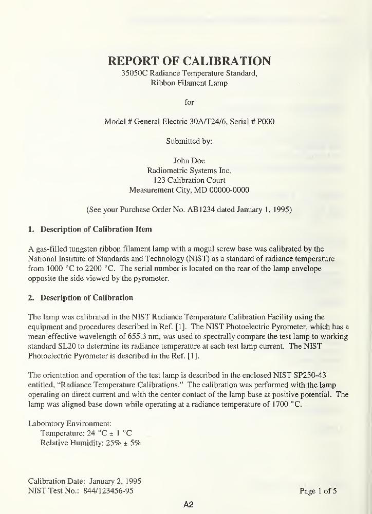
REPORT OF CALIBRATION35050C Radiance Temperature Standard,
Ribbon Filament Lamp
for
Model # General Electric 30A/T24/6, Serial # P000
Submitted by:
John Doe
Radiometric Systems Inc.
123 Calibration Court
Measurement City, MD 00000-0000
(See your Purchase Order No. AB 1 234 dated January 1 , 1995)
1. Description of Calibration Item
A gas-filled tungsten ribbon filament lamp with a mogul screw base was calibrated by the
National Institute of Standards and Technology (NIST) as a standard of radiance temperature
from 1000 °C to 2200 °C. The serial number is located on the rear of the lamp envelope
opposite the side viewed by the pyrometer.
2. Description of Calibration
The lamp was calibrated in the NIST Radiance Temperature Calibration Facility using the
equipment and procedures described in Ref. [11. The NIST Photoelectric Pyrometer, which has a
mean effective wavelength of 655.3 nm, was used to spectrally compare the test lamp to working
standard SL20 to determine its radiance temperature at each test lamp current. The NISTPhotoelectric Pyrometer is described in the Ref. [1].
The orientation and operation of the test lamp is described in the enclosed NIST SP250-43
entitled, "Radiance Temperature Calibrations." The calibration was performed with the lamp
operating on direct current and with the center contact of the lamp base at positive potential. The
lamp was aligned base down while operating at a radiance temperature of 1700 °C.
Laboratory Environment:
Temperature: 24 °C ± 1 °C
Relative Humidity: 25% ± 5%
Calibration Date: January 2, 1995
NIST Test No.: 844/123456-95
A2
Page 1 of 5
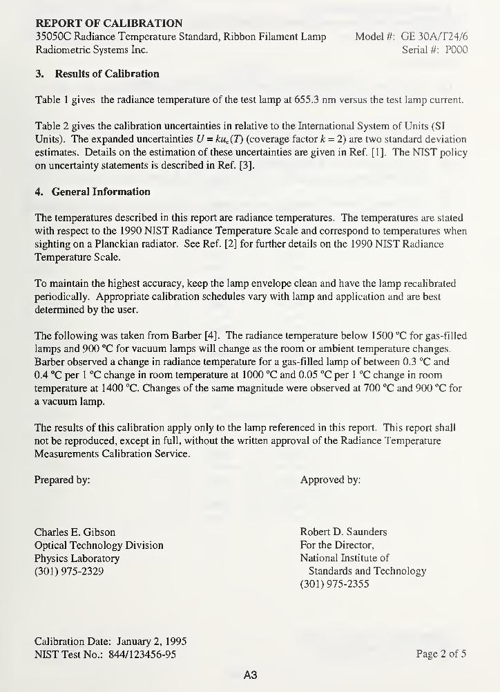
REPORT OF CALIBRATION35050C Radiance Temperature Standard, Ribbon Filament Lamp Model #: GE 30A/T24/6
Radiometric Systems Inc. Serial #: P000
3. Results of Calibration
Table 1 gives the radiance temperature of the test lamp at 655.3 nm versus the test lamp current.
Table 2 gives the calibration uncertainties in relative to the International System of Units (SI
Units). The expanded uncertainties U = kuc (T) (coverage factor k = 2) are two standard deviation
estimates. Details on the estimation of these uncertainties are given in Ref. [1]. The NIST policy
on uncertainty statements is described in Ref. [3].
4. General Information
The temperatures described in this report are radiance temperatures. The temperatures are stated
with respect to the 1990 NIST Radiance Temperature Scale and correspond to temperatures when
sighting on a Planckian radiator. See Ref. [2] for further details on the 1990 NIST Radiance
Temperature Scale.
To maintain the highest accuracy, keep the lamp envelope clean and have the lamp recalibrated
periodically. Appropriate calibration schedules vary with lamp and application and are best
determined by the user.
The following was taken from Barber [4]. The radiance temperature below 1500 °C for gas-filled
lamps and 900 °C for vacuum lamps will change as the room or ambient temperature changes.
Barber observed a change in radiance temperature for a gas-filled lamp of between 0.3 °C and
0.4 °C per 1 °C change in room temperature at 1000 °C and 0.05 °C per 1 °C change in room
temperature at 1400 °C. Changes of the same magnitude were observed at 700 °C and 900 °C for
a vacuum lamp.
The results of this calibration apply only to the lamp referenced in this report. This report shall
not be reproduced, except in full, without the written approval of the Radiance Temperature
Measurements Calibration Service.
Prepared by: Approved by:
Charles E. Gibson
Optical Technology Division
Physics Laboratory
(301) 975-2329
Robert D. Saunders
For the Director,
National Institute of
Standards and Technology
(301) 975-2355
Calibration Date: January 2, 1995
NIST Test No.: 844/123456-95 Page 2 of 5
A3
REPORT OF CALIBRATION35050C Radiance Temperature Standard, Ribbon Filament Lamp Model #: GE 30A/T24/6
Radiometric Systems Inc. Serial #: P000
References
[1] C. E. Gibson, B. K. Tsai, and A. C. Parr, "Radiance Temperature Calibrations," NIST
Special Publication 250-43 (1997).
[2] K. D. Mielenz, R. D. Saunders, A. C. Parr, and J. J. Hsia, "The 1990 NIST Scales of
Thermal Radiometry," /. Res. Natl. Inst. Stand. Technol., 95, 621-629, (1990).
[3] B. N. Taylor and C. E. Kuyatt, "Guidelines for Evaluating and Expressing the Uncertainty
of the NIST Measurement Results," NIST Technical Note 1297 (2nd ed., 1994).
[4] C. R. Barber, "Factors affecting the reproducibility of brightness of tungsten strip lamps for
pyrometry standardization," J. Sci. Instr. 23, 238 (1946).
Calibration Date: January 2, 1995
NIST Test No. : 844/ 1 23456-95
A4
Page 3 of 5
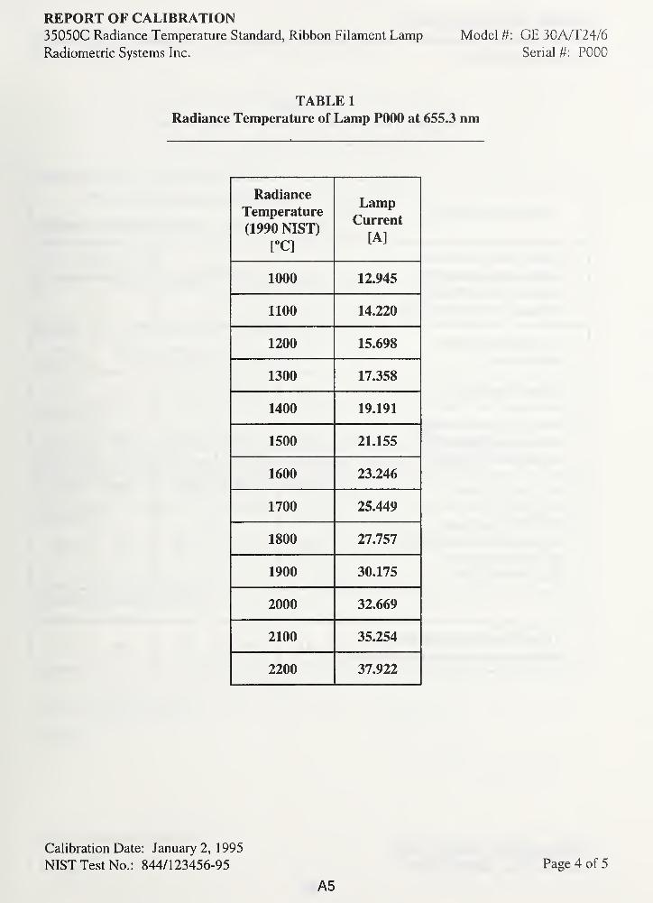
REPORT OF CALIBRATION35050C Radiance Temperature Standard, Ribbon Filament LampRadiometric Systems Inc.
Model #: GE 30A/T24/6
Serial #: P000
TABLE 1
Radiance Temperature of Lamp P000 at 655.3 nm
Radiance
Temperature
(1990 NIST)
L
LampCurrent
[A]
1000 12 945
1100 14 220
1200 15 698
1300 17 358
1400 19 191
1500 21 155
1600JLvvv 23 246
1700 25.449
1800 27.757
1900 30.175
2000 32.669
2100 35.254
2200 37.922
Calibration Date: January 2, 1 995
NIST Test No.: 844/123456-95
A5
Page 4 of 5
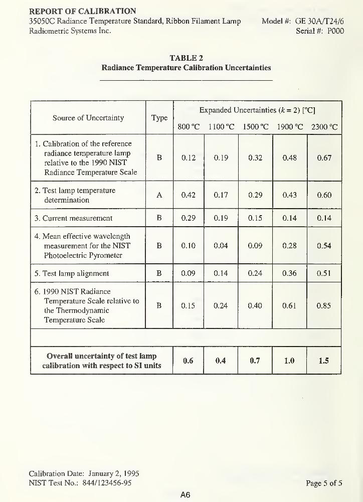
REPORT OF CALIBRATION35050C Radiance Temperature Standard, Ribbon Filament LampRadiometric Systems Inc.
Model #: GE 30A/T24/6
Serial #: P000
TABLE 2
Radiance Temperature Calibration Uncertainties
Source of Uncertainty TypeExpanded Uncertainties (k = 2) [°C]
800 °C 1100°C 1500 °C 1900 °C 2300 °C
1 . Calibration of the reference
radiance temperature lamp
relative to the 1 990 NTST
Radiance Temperature Scale
B 0.12 0.19 0.32 0.48 0.67
2. Test lamp temperature
determinationA 0.42 f\ in0.17 0.29 0.43 0.60
3. Current measurement B 0.29 0.19 0.15 0.14 0.14
4. Mean effective wavelength
measurement for the NISTPhotoelectric Pyrometer
B 0.10 0.04 0.09 0.28 0.54
5. Test lamp alignment B 0.09 0.14 0.24 0.36 0.51
6. 1990 NIST Radiance
Temperature Scale relative to
the Thermodynamic
Temperature Scale
B 0.15 0.24 0.40 0.61 0.85
Overall uncertainty of test lamp
calibration with respect to SI units0.6 0.4 0.7 1.0 1.5
Calibration Date: January 2, 1995
NIST Test No.: 844/123456-95
A6
Page 5 of 5
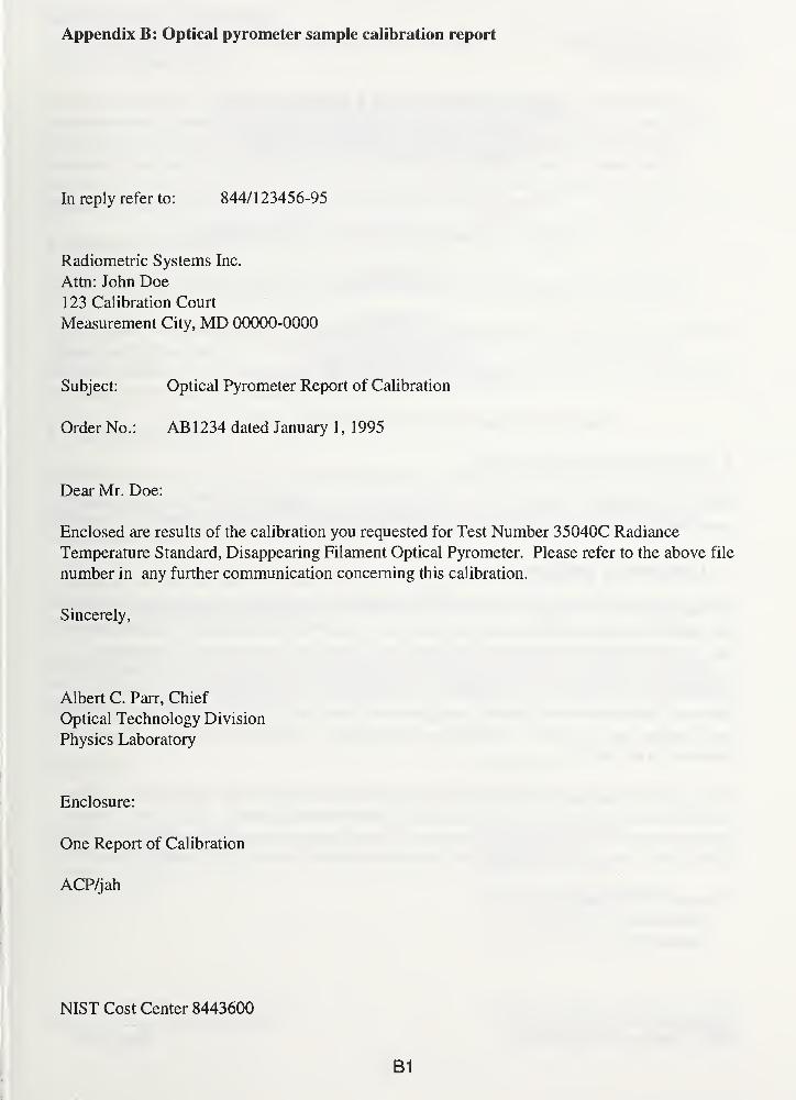
Appendix B: Optical pyrometer sample calibration report
In reply refer to: 844/123456-95
Radiometric Systems Inc.
Attn: John Doe
123 Calibration Court
Measurement City, MD 00000-0000
Subject: Optical Pyrometer Report of Calibration
Order No. : AB 1 234 dated January 1,1995
Dear Mr. Doe:
Enclosed are results of the calibration you requested for Test Number 35040C Radiance
Temperature Standard, Disappearing Filament Optical Pyrometer. Please refer to the above file
number in any further communication concerning this calibration.
Sincerely,
Albert C. Parr, Chief
Optical Technology Division
Physics Laboratory
Enclosure:
One Report of Calibration
ACP/jah
NIST Cost Center 8443600
B1
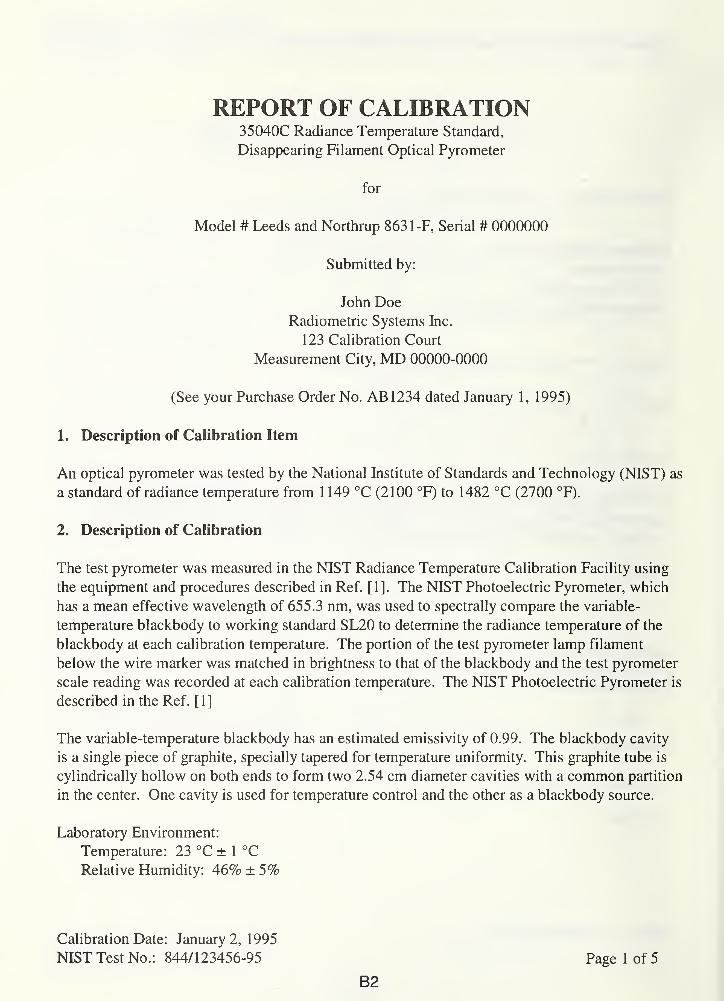
REPORT OF CALIBRATION35040C Radiance Temperature Standard,
Disappearing Filament Optical Pyrometer
for
Model # Leeds and Northrup 863 1-F, Serial # 0000000
Submitted by:
John DoeRadiometric Systems Inc.
123 Calibration Court
Measurement City, MD 00000-0000
(See your Purchase Order No. AB1234 dated January 1, 1995)
1. Description of Calibration Item
An optical pyrometer was tested by the National Institute of Standards and Technology (NIST) as
a standard of radiance temperature from 1 149 °C (2100 °F) to 1482 °C (2700 °F).
2. Description of Calibration
The test pyrometer was measured in the NIST Radiance Temperature Calibration Facility using
the equipment and procedures described in Ref. [1]. The NIST Photoelectric Pyrometer, which
has a mean effective wavelength of 655.3 nm, was used to spectrally compare the variable-
temperature blackbody to working standard SL20 to determine the radiance temperature of the
blackbody at each calibration temperature. The portion of the test pyrometer lamp filament
below the wire marker was matched in brightness to that of the blackbody and the test pyrometer
scale reading was recorded at each calibration temperature. The NIST Photoelectric Pyrometer is
described in the Ref. [ 1 ]
The variable-temperature blackbody has an estimated emissivity of 0.99. The blackbody cavity
is a single piece of graphite, specially tapered for temperature uniformity. This graphite tube is
cylindrically hollow on both ends to form two 2.54 cm diameter cavities with a common partition
in the center. One cavity is used for temperature control and the other as a blackbody source.
Laboratory Environment:
Temperature: 23 °C ± 1 °C
Relative Humidity: 46% ±5%
Calibration Date: January 2, 1995
NIST Test No.: 844/1 23456-95 Page 1 of 5
B2

REPORT OF CALIBRATION35040C Radiance Temperature Standard, Optical Pyrometer
Radiometric Systems Inc.
Model #: L&N 8631-F
Serial #: 0000000
The test pyrometer was operated according to the manufacturer's operating instructions. The
pyrometer was calibrated from 1 149 °C (2100 °F) to 1482 °C (2700 °F) on the high range (H).
The pyrometer was aligned so that its optical axis, when viewing the variable-temperature
blackbody, coincided with the geometrical center of the blackbody. The pyrometer was
measured at a distance of 81 .7 cm from the front surface of the objective lens holder to the
blackbody cavity partition and was focussed on the center of the partition.
3. Results of Calibration
Table 1 gives the radiance temperature at 655.3 nm versus the test pyrometer scale reading.
Table 2 gives the calibration uncertainties relative to the International System of Units (SI Units).
The expanded uncertainties U = kuc (T) (coverage factor k = 2) are two standard deviation
estimates. Details on the estimation of these uncertainties are given in Ref. [1]. The NIST policy
on uncertainty statements is described in Ref. [3].
4. General Information
The temperatures described in this report are radiance temperatures. The temperatures are stated
with respect to the 1990 NIST Radiance Temperature Scale and correspond to temperatures when
sighting on a Planckian radiator. See Ref. [2] for further details on the 1990 NIST Radiance
Temperature Scale.
To maintain the highest accuracy, keep the optical components clean and have the pyrometer
recalibrated periodically. Appropriate calibration schedules vary with instrument and application
and are best determined by the user.
The results of this calibration apply only to the pyrometer referenced in this report. This report
shall not be reproduced, except in full, without the written approval of the Radiance Temperature
Measurements Calibration Service.
Prepared by:
Charles E. Gibson
Optical Technology Division
Physics Laboratory
(301)975-2329
Approved by:
Robert D. Saunders
For the Director,
National Institute of
Standards and Technology
(301)975-2355
Calibration Date: January 2, 1 995
NIST Test No.: 844/123456-95
B3
Page 2 of 5

REPORT OF CALIBRATION35040C Radiance Temperature Standard, Optical Pyrometer
Radiometric Systems Inc.
Model #: L&N 863 1-F
Serial #: 0000000
References
[1] C. E. Gibson, B. K. Tsai, and A. C. Parr, "Radiance Temperature Calibrations," NIST
Special Publication 250-43 (1997).
[2] K. D. Mielenz, R. D. Saunders, A. C. Parr, and J. J. Hsia, "The 1990 NIST Scales of
Thermal Radiometry," J. Res. Natl. Inst. Stand. Technol., 95, 621-629, (1990).
[3] B. N. Taylor and C. E. Kuyatt, "Guidelines for Evaluating and Expressing the Uncertainty
of the NIST Measurement Results," NIST Technical Note 1297 (2nd ed., 1994).
Calibration Date: January 2, 1995
NIST Test No.: 844/123456-95 Page 3 of 5
B4
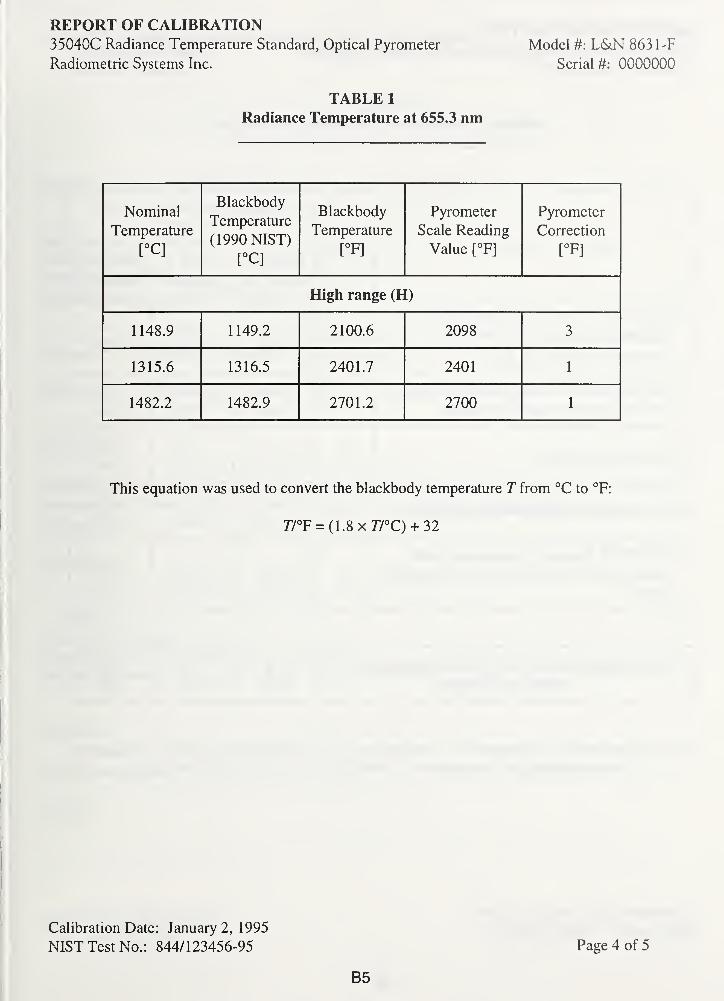
REPORT OF CALIBRATION35040C Radiance Temperature Standard, Optical Pyrometer
Radiometric Systems Inc.
Model #: L&N 8631-F
Serial #: 0000000
TABLE 1
Radiance Temperature at 655.3 nm
Nominal
Temperature
[°C]
Blackbody
Temperature
(1990 NIST)
[°C]
Blackbody
Temperature
[°F]
Pyrometer
Scale Reading
Value [°F]
Pyrometer
Correction
[°F]
High range (H)
1148.9 1149.2 2100.6 2098 3
1315.6 1316.5 2401.7 2401 1
1482.2 1482.9 2701.2 2700 1
This equation was used to convert the blackbody temperature T from °C to °F:
r/°F = (1.8x77°C) + 32
Calibration Date: January 2, 1995
NIST Test No.: 844/123456-95
B5
Page 4 of 5
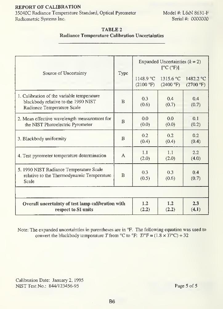
REPORT OF CALIBRATION35040C Radiance Temperature Standard, Optical Pyrometer
Radiometric Systems Inc.
Model #: L&N 863 1-F
Serial #: 0000000
TABLE 2
Radiance Temperature Calibration Uncertainties
Source of Uncertainty Tvoe
Expanded Uncertainties (k = 2)
[°C (°F)]
1148.9 °C 1315.6 °C 1482.2 °C
(2100 °F) (2400 °F) (2700 °F)
1 . Calibration of the variable temperature
blackbody relative to the 1990 NIST
lxu.LiIo.IlCC 1 ClllUvluLUlw Jtait/
B0.3
(0.6)
0.4
(0.7)
0.4
(0.7)
2. Mean effective wavelength measurement for
the NIST Photoelectric PyrometerB
0.0
(0.0)
0.0
(0.0)
0.1
(0.2)
3. Blackbody uniformity B0.2
(0.4)
0.2
(0.4)
0.2
(0.4)
4. Test pyrometer temperature determination A 1.1
(2.0)
u(2.0)
2.2
(4.0)
5. 1990 NIST Radiance Temperature Scale
relative to the Thermodynamic Temperature
Scale
B0.3
(0.5)
0.3
(0.6)
0.4
(0.7)
Overall uncertainty of test lamp calibration with
respect to SI units
1.2
(2.2)
1.2
(2.2)
2.3
(4.1)
Note: The expanded uncertainties in parentheses are in °F. The following equation was used to
convert the blackbody temperature Tfrom °C to °F: 77°F = (1.8 x 77°C) + 32
Calibration Date: January 2, 1995
NIST Test No.: 844/123456-95 Page 5 of 5
B6
Appendix C: Radiation thermometer sample calibration report
In reply refer to: 844/1 23456-95
Radiometric Systems Inc.
Attn: John Doe
123 Calibration Court
Measurement City, MD 00000-0000
Subject: Radiation Thermometer Report of Test
Order No. : AB 1 234 dated January 1,1995
Dear Mr. Doe:
Enclosed are results of the test you requested for Test Number 35070S Special Test of Radiation
Thermometer. Please refer to the above file number in any further communication concerning
this test.
Sincerely,
Albert C. Parr, Chief
Optical Technology Division
Physics Laboratory
Enclosure:
One Report of Test
ACP/jah
NIST Cost Center 8443600
C1
REPORT OF TEST35070S Special Test of Radiation Thermometer
for
Model # Minolta-Land Cyclops 52, Serial # 00000000
Submitted by:
John DoeRadiometric Systems Inc.
123 Calibration Court
Measurement City, MD 00000-0000
(See your Purchase Order No. AB1234 dated January 1, 1995)
1. Description of Test Item
A radiation thermometer was tested by the National Institute of Standards and Technology
(NIST) as a standard of radiance temperature from 800 °C to 2300 °C. The test unit was
measured with clear filter (Serial Number 0) and dark filter (Serial Number 0).
2. Description of Test
The test thermometer was measured in the NIST Radiance Temperature Calibration Facility
using the equipment and procedures described in Ref. [1]. The NIST Photoelectric Pyrometer,
which has a mean effective wavelength of 655.3 nm, was used to spectrally compare the variable-
temperature blackbody to working standard SL20 to determine the radiance temperature of the
blackbody at each calibration temperature. The test thermometer display panel value was
recorded at each calibration temperature. The NIST Photoelectric Pyrometer is described in the
Ref. [1]
The variable-temperature blackbody has an estimated emissivity of 0.99. The blackbody cavity
is a single piece of graphite, specially tapered for temperature uniformity. This graphite tube is
cylindrically hollow on both ends to form two 2.54 cm diameter cavities with a common partition
in the center. One cavity is used for temperature control and the other as a blackbody source.
Laboratory Environment:
Temperature: 23 °C ± 1 °C
Relative Humidity: 46% ± 5%
Test Date: January 2, 1 995
NIST Test No.: 844/123456-95 Page 1 of 5
C2
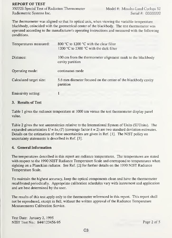
REPORT OF TEST35070S Special Test of Radiation Thermometer
Radiometric Systems Inc.
Model #: Minolta-Land Cyclops 52
Serial #: 00000000
The thermometer was aligned so that its optical axis, when viewing the variable-temperature
blackbody, coincided with the geometrical center of the blackbody. The test thermometer was
operated according to the manufacturer's operating instructions and measured with the following
conditions.
Temperatures measured: 800 °C to 1200 °C with the clear filter
1 200 °C to 2300 °C with the dark filter
Distance:
Operating mode:
Calculated target size:
Emissivity setting:
3. Results of Test
100 cm from the thermometer alignment mark to the blackbody
cavity partition
continuous mode
5.6 mm diameter focused on the center of the blackbody cavity
partition
1
Table 1 gives the radiance temperature at 1000 nm versus the test thermometer display panel
value.
Table 2 gives the test uncertainties relative to the International System of Units (SI Units). The
expanded uncertainties U - kuc (T) (coverage factor k = 2) are two standard deviation estimates.
Details on the estimation of these uncertainties are given in Ref. [1]. The NIST policy on
uncertainty statements is described in Ref. [3].
4. General Information
The temperatures described in this report are radiance temperatures. The temperatures are stated
with respect to the 1990 NIST Radiance Temperature Scale and correspond to temperatures when
sighting on a Planckian radiator. See Ref. [2] for further details on the 1990 NIST Radiance
Temperature Scale.
To maintain the highest accuracy, keep the optical components clean and have the thermometer
recalibrated periodically. Appropriate calibration schedules vary with instrument and application
and are best determined by the user.
The results of this test apply only to the thermometer referenced in this report. This report shall
not be reproduced, except in full, without the written approval of the Radiance Temperature
Measurements Calibration Service.
Test Date: January 2, 1 995
NIST Test No.: 844/123456-95 Page 2 of 5
C3
REPORT OF TEST35070S Special Test of Radiation Thermometer
Radiometric Systems Inc.
Model #: Minolta-Land Cyclops 52
Serial #: 00000000
Prepared by: Approved by:
Charles E. Gibson
Optical Technology Division
Physics Laboratory
(301)975-2329
Robert D. Saunders
For the Director,
National Institute of
Standards and Technology
(301)975-2355
References
[1] C. E. Gibson, B. K. Tsai, and A. C. Parr, "Radiance Temperature Calibrations," NISTSpecial Publication 250-43 (1997).
[2] K. D. Mielenz, R. D. Saunders, A. C. Parr, and J. J. Hsia, "The 1990 NIST Scales of
Thermal Radiometry," J. Res. Natl. Inst. Stand. Technol., 95, 621-629, (1990).
[3] B. N. Taylor and C. E. Kuyatt, "Guidelines for Evaluating and Expressing the Uncertainty
of the NIST Measurement Results," NIST Technical Note 1297 (2nd ed., 1994).
Test Date: January 2, 1995
NIST Test No.: 844/123456-95 Page 3 of 5
C4
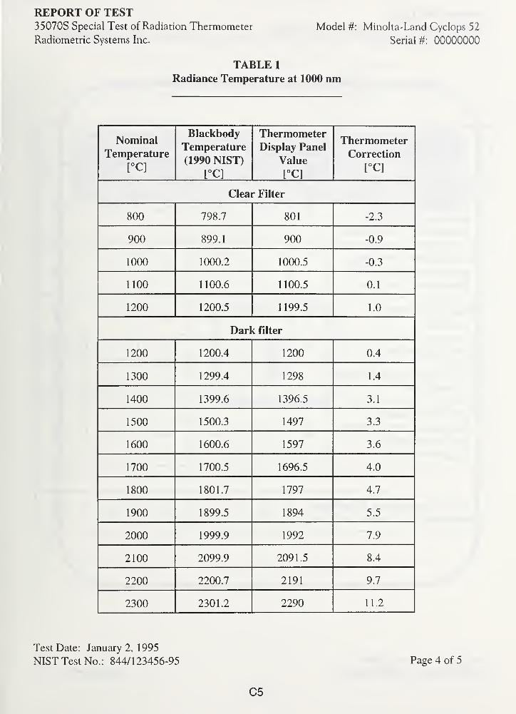
REPORT OF TEST35070S Special Test of Radiation Thermometer
Radiometric Systems Inc.
Model #: Minolta-Land Cyclops 52
Serial #: 00000000
TABLE 1
Radiance Temperature at 1000 nm
Nominal
Temperature
[°C]
Blackbody
Temperature
(1990 NIST)
[°C]
ThermometerDisplay Panel
Value
[°C]
Thermometer
Correction
[°C]
Clear Filter
800 798.7 801 -2.3
900 899.1 900 -0.9
1000 1000.2 1000.5 -0.3
1100 1 100.6 1100.5 0.1
1200 1200.5 1199.5 1.0
Dark filter
1200 1200.4 1200 0.4
1300 1299.4 1298 1.4
1400 1399.6 1396.5 3.1
1500 1500.3 1497 3.3
1600 1600.6 1597 3.6
1700 1700.5 1696.5 4.0
1800 1801.7 1797 4.7
1900 1899.5 1894 5.5
2000 1999.9 1992 7.9
2100 2099.9 2091.5 8.4
2200 2200.7 2191 9.7
2300 2301.2 2290 11.2
Test Date: January 2, 1995
NIST Test No.: 844/123456-95 Page 4 of 5
C5
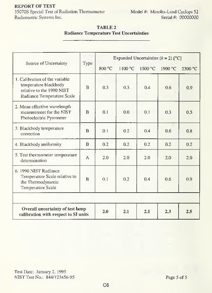
REPORT OF TEST35070S Special Test of Radiation Thermometer
Radiometric Systems Inc.
Model #: Minolta-Land Cyclops 52
Serial #: 00000000
TABLE 2
Radiance Temperature Test Uncertainties
Source of Uncertainty Type
Expanded Uncertainties (k = 2) [°C]
800 °C 1100°C 1500 °C 1900 °C 2300 °C
1 . Calibration of the variable
temperature blackbody
relative to the 1990 NIST
Radiance Temperature Scale
B 0.3 0.3 0.4 0.6 0.9
2. Mean effective wavelength
measurement for the NIST
Photoelectric Pyrometer
B 0.1 0.0 0.1 0.3 0.5
3. Blackbody temperature
correctionB 0.1 0.2 0.4 0.6 0.8
4. Blackbody uniformity B 0.2 0.2 0.2 0.2 0.2
5. Test thermometer temperature
determinationA 2.0 2.0 2.0 2.0 2.0
6. 1990 NIST Radiance
Temperature Scale relative to
the Thermodynamic
Temperature Scale
B 0.1 0.2 0.4 0.6 0.9
Overall uncertainty of test lamp
calibration with respect to SI units2.0 2.1 2.1 2.3 2.5
Test Date: January 2, 1995
NIST Test No.: 844/123456-95
C6
Page 5 of 5
Appendix D: Radiance temperature measurement services laboratory procedure manual
Radiance Temperature MeasurementsLaboratory Procedures Manual
v J
D1
Safety Issues
Safety glasses are required in lab at all times.
The following hazards have been identified in this lab. Safety measures are in place to reduce
risk of injury from hazards below.
BRIGHT SOURCEStaring at source is to be avoided because staring can cause severe eye damage. Using correct
neutral density filter when viewing is required
BURNTo avoid burns, it is wise to keep body and clothes away from lamps and blackbodies.
COLLISIONThe boxcar path should be kept clear of collision with any objects, and cables should not be hung
from boxcar at any time.
ELECTROCUTIONSince high voltage connections are present, electrical parts should not be touched at all.
LASERAs with other bright sources, staring into laser is to be avoided because staring can cause severe
eye damage. When lasers are not in use, block laser with opaque object and turn off laser when it
is not in use.
Symbols, similar to one below, are used throughout this document to alert operator to potential
hazards.
LASER
G:\LPManual\RTMLP Safety. 1
D2
Page 1

Optical Technology Division (844)
Radiance Temperature Measurements Laboratory Procedures
Table of Contents
i. Safety Issues
1. Running General Data Taking Program (RTMLP1
)
2. NIST Photoelectric Pyrometer (PEP) Operation (RTMLP2)
3. Gold-point Blackbody (GPBB) Alignment (RTMLP3)
4. Gold-point Blackbody Operation (RTMLP4)
5. Ribbon Filament Lamp Preparation (RTMLP5)
6. Ribbon Filament Lamp Alignment (RTMLP6)
7. Ribbon Filament Lamp Operation (RTMLP7)
8. Ribbon Filament Lamp Calibration Procedure (RTMLP8)
9. Ribbon Filament Lamp Data Reduction (RTMLP9)
10. Variable Temperature Blackbody (BB) Alignment (RTMLP 10)
11. Variable Temperature Blackbody Operation (RTMLP 1 1)
12. Disappearing Filament Optical Pyrometer Alignment (RTMLP 12)
13. Radiation Thermometer (RT) Alignment (RTMLP 13)
14. Radiation Thermometer (Optical Pyrometer) Calibration Procedure (RTMLP 14)
15. Radiation Thermometer Data Reduction (RTMLP 15)
G:\LPManual\RTMTOC. 1
D3
Page 1 of 1
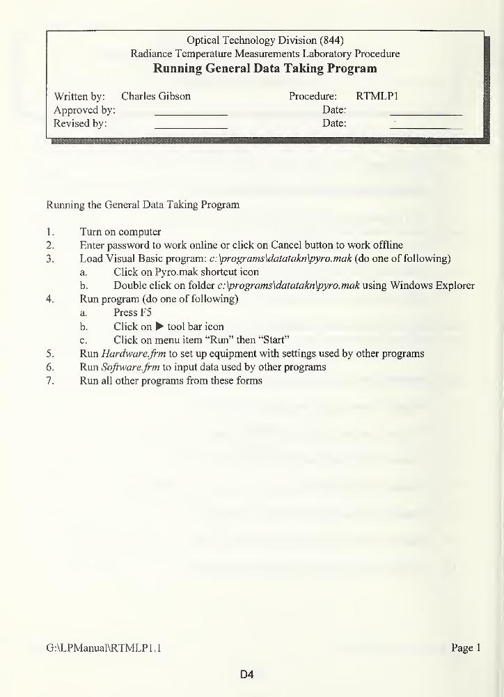
Optical Technology Division (844)
Radiance Temperature Measurements Laboratory Procedure
Running General Data Taking Program
Written by:
Approved by:
Revised by:
Charles Gibson Procedure: RTMLP1Date: _Date:
Running the General Data Taking Program
1 . Turn on computer
2. Enter password to work online or click on Cancel button to work offline
3. Load Visual Basic program: c:\programs\datatakn\pyro.mak (do one of following)
a. Click on Pyro.mak shortcut icon
b. Double click on folder c: \programs\datatakn\pyro. mak using Windows Explorer
4. Run program (do one of following)
a. Press F5
b. Click on tool bar icon
c. Click on menu item "Run" then "Start"
5. Run Hardware.frm to set up equipment with settings used by other programs
6. Run Software.frm to input data used by other programs
7. Run all other programs from these forms
G:\LPManual\RTMLPl.l
D4
Page 1
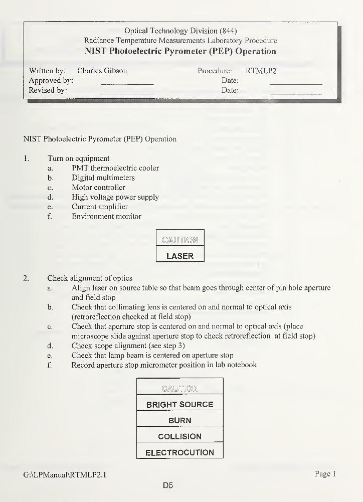
Optical Technology Division (844)
Radiance Temperature Measurements Laboratory Procedure
NIST Photoelectric Pyrometer (PEP) Operation
Written by: Charles Gibson Procedure: RTMLP2Approved by: Date:
Revised by: Date:
NIST Photoelectric Pyrometer (PEP) Operation
1 . Turn on equipment
a. PMT thermoelectric cooler
b. Digital multimeters
c. Motor controller
d. High voltage power supply
e. Current amplifier
f. Environment monitor
TO
LASER
2. Check alignment of optics
a. Align laser on source table so that beam goes through center of pin hole aperture
and field stop
b. Check that collimating lens is centered on and normal to optical axis
(retroreflection checked at field stop)
c. Check that aperture stop is centered on and normal to optical axis (place
microscope slide against aperture stop to check retroreflection at field stop)
d. Check scope alignment (see step 3)
e. Check that lamp beam is centered on aperture stop
f. Record aperture stop micrometer position in lab notebook
BRIGHT SOURCE
BURN
COLLISION
ELECTROCUTION
G:\LPManual\RTMLP2.1
D5
Page 1

Optical Technology Division (844)
Radiance Temperature Measurements Laboratory Procedure
Procedure RTMLP2: Photoelectric Pyrometer (PEP) Operation
3. Check scope alignment (scope is used to define optical axis of PEP)
a. Turn on SL20 or other lamp in focal plane of PEP (see RTMLP7)b. Move lamp to PEP
c. Close PMT shutter
d. Open enclosure doors
e. Open scope door
f. Place 3/4" aperture on objective lens
g. Put in field stop
h. Put in prism
i. Focus reticle to operator's eye
j. Focus scope on field stop
k. Rotate reticle so that #5 vertical scale line is parallel to side of field stop opening
1. Position reticle center (intersection of #5 vertical scale line and horizontal scale
line) on field stop opening
m. Remove prism
n. Remove field stop
o. Put in prism
4. Set up PEP for measurements
a. Remove aperture from objective lens
b. Remove prism
c. Close scope door
d. Put in field stop
e. Close all enclosure doors
f. Position baffles at front of PEP
g. Open PMT shutter
h. Begin calibration (see (RTMLP8) for lamps or (RTMLP14) for radiation
thermometers)
G:\LPManual\RTMLP2.
1
D6
Page 2
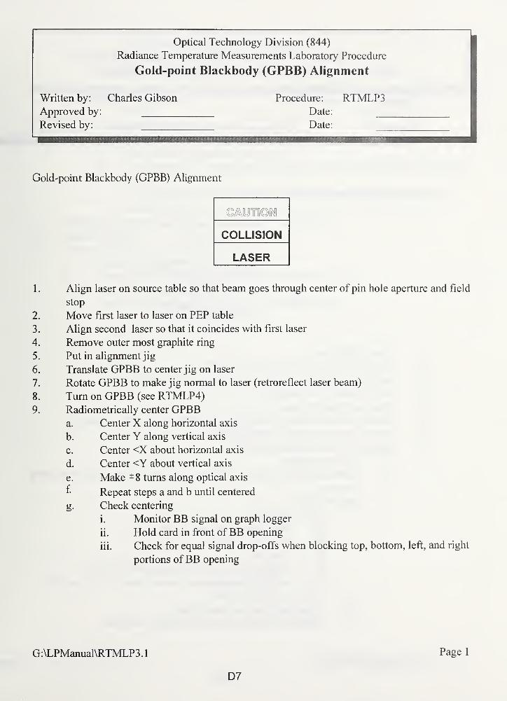
,
Optical Technology Division (844)
Radiance Temperature Measurements Laboratory Procedure
Gold-point Blackbody (GPBB) Alignment
Written by: Charles Gibson Procedure: RTMLP3Approved by: Date:
Revised by: Date:
WBMllWni^
Gold-point Blackbody (GPBB) Alignment
COLLISION
LASER
1 . Align laser on source table so that beam goes through center of pin hole aperture and field
stop
2. Move first laser to laser on PEP table
3. Align second laser so that it coincides with first laser
4. Remove outer most graphite ring
5. Put in alignment jig
6. Translate GPBB to center jig on laser
7. Rotate GPBB to make jig normal to laser (retroreflect laser beam)
8. Turn on GPBB (see RTMLP4)9. Radiometrically center GPBB
a. Center X along horizontal axis
b. Center Y along vertical axis
c. Center <X about horizontal axis
d. Center <Y about vertical axis
e. Make -8 turns along optical axis
f- Repeat steps a and b until centered
g. Check centering
i. Monitor BB signal on graph logger
ii. Hold card in front ofBB opening
iii. Check for equal signal drop-offs when blocking top, bottom, left, and right
portions ofBB opening
G:\LPManual\RTMLP3 .
1
D7
Page 1
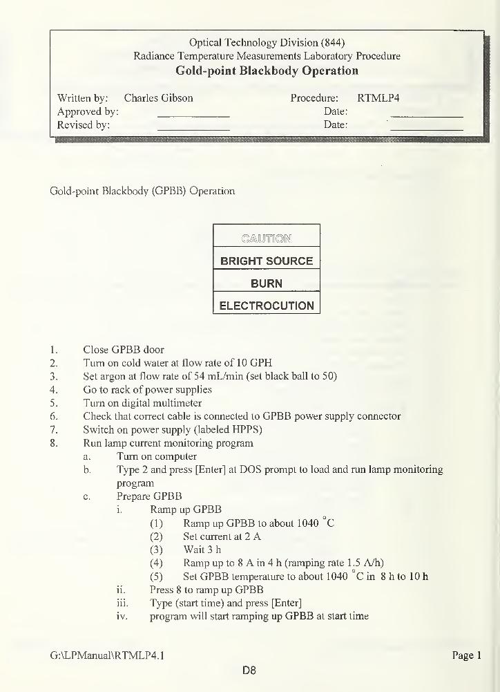
Optical Technology Division (844)
Radiance Temperature Measurements Laboratory Procedure
Gold-point Blackbody Operation
Written by: Charles Gibson Procedure: RTMLP4Approved by: Date:
Revised by: Date:
Gold-point Blackbody (GPBB) Operation
TO
BRIGHT SOURCE
BURN
ELECTROCUTION
1. Close GPBB door
2. Turn on cold water at flow rate of 10 GPH3. Set argon at flow rate of 54 mL/min (set black ball to 50)
4. Go to rack of power supplies
5. Turn on digital multimeter
6. Check that correct cable is connected to GPBB power supply connector
7. Switch on power supply (labeled HPPS)
8. Run lamp current monitoring program
a. Turn on computer
b. Type 2 and press [Enter] at DOS prompt to load and run lamp monitoring
program
c. Prepare GPBBi. Ramp up GPBB
( 1 ) Ramp up GPBB to about 1 040 °C(2) Set current at 2 A(3) Wait 3 h
(4) Ramp up to 8 A in 4 h (ramping rate 1 .5 A/h)
(5) Set GPBB temperature to about 1040 °C in 8 h to 10 h
ii. Press 8 to ramp up GPBBiii. Type (start time) and press [Enter]
iv. program will start ramping up GPBB at start time
G:\LPManual\RTMLP4.1
D8
Page 1
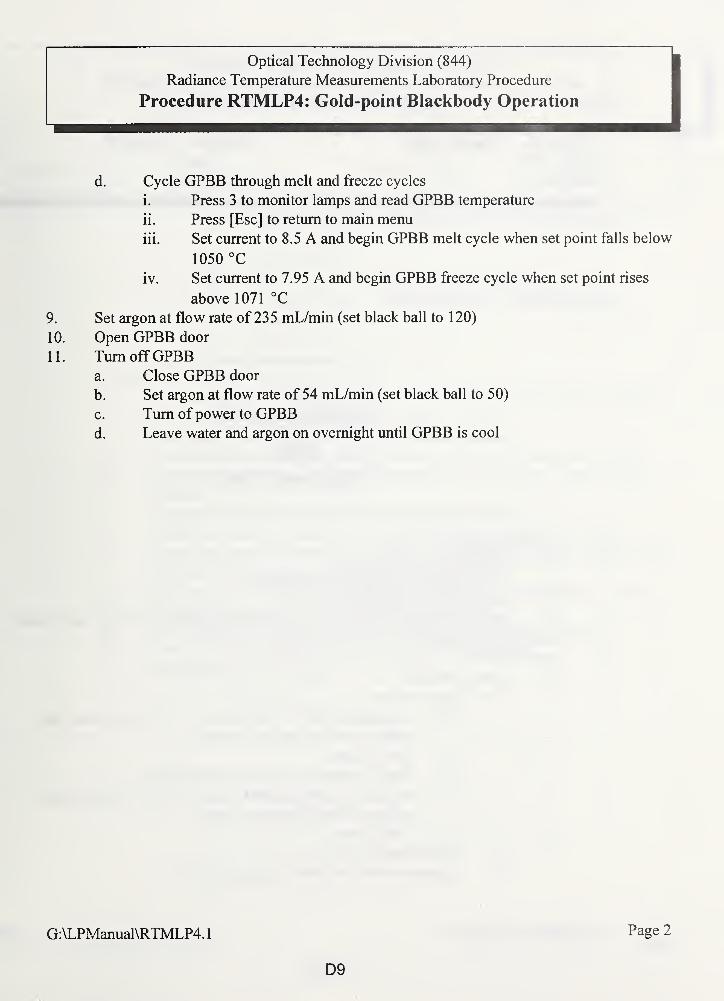
Optical Technology Division (844)
Radiance Temperature Measurements Laboratory Procedure
Procedure RTMLP4: Gold-point Blackbody Operation
d. Cycle GPBB through melt and freeze cycles
i. Press 3 to monitor lamps and read GPBB temperature
ii. Press [Esc] to return to main menu
iii. Set current to 8.5 A and begin GPBB melt cycle when set point falls below
1050 °C
iv. Set current to 7.95 A and begin GPBB freeze cycle when set point rises
above 1071 °C
9. Set argon at flow rate of 235 mL/min (set black ball to 1 20)
10. Open GPBB door
11. Turn offGPBBa. Close GPBB door
b. Set argon at flow rate of 54 mL/min (set black ball to 50)
c. Turn of power to GPBBd. Leave water and argon on overnight until GPBB is cool
G:\LPManual\RTMLP4.
1
D9
Page 2
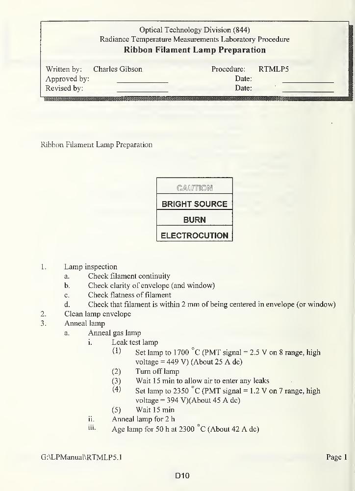
Optical Technology Division (844)
Radiance Temperature Measurements Laboratory Procedure
Ribbon Filament Lamp Preparation
Written by: Charles Gibson Procedure: RTMLP5Approved by: Date:
Revised by: Date:
Ribbon Filament Lamp Preparation
BRIGHT SOURCE
BURN
ELECTROCUTION
Lamp inspection
a. Check filament continuity
b. Check clarity of envelope (and window)
c. Check flatness of filament
d. Check that filament is within 2 mm of being centered in envelope (or window)
Clean lamp envelope
Anneal lamp
a. Anneal gas lamp
i. Leak test lamp
(!) Set lamp to 1700 °C (PMT signal = 2.5 V on 8 range, high
voltage = 449 V) (About 25 A dc)
(2) Turn off lamp
(3) Wait 1 5 min to allow air to enter any leaks
(4) Set lamp to 2350 °C (PMT signal = 1 .2 V on 7 range, high
voltage = 394 V)(About 45 A dc)
(5) Wait 15 min
ii. Anneal lamp for 2 hiii- Age lamp for 50 h at 2300 °C (About 42 A dc)
G:\LPManual\RTMLP5 .
1
Page 1
D10
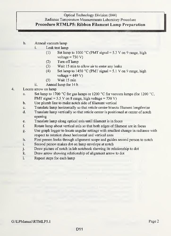
Optical Technology Division (844)
Radiance Temperature Measurements Laboratory Procedure
Procedure RTMLP5: Ribbon Filament Lamp Preparation
b. Anneal vacuum lamp
i. Leak test lamp
(1) Set lamp to 1000 °C (PMT signal = 5.3 V on 9 range, high
voltage = 730 V)
(2) Turn off lamp
(3) Wait 15 min to allow air to enter any leaks
(4) Set lamp to 1450 °C (PMT signal - 5. 1 V on 9 range, high
voltage = 449 V)
(5) Wait 15 min
ii. Anneal lamp for 14 h
4. Locate arrow on lamp
a. Set lamp to 1700 °C for gas lamps or 1200 °C for vacuum lamps (for 1200 °C,
PMT signal = 5.5 V on 8 range, high voltage = 730 V)
b. Use plumb line to make notch side of filament vertical
c. Translate lamp horizontally so that reticle center bisects filament lengthwise
d. Translate lamp vertically so that reticle center is positioned at center of notch
opening
e. Translate lamp along optical axis until filament is in focus
f. Rotate lamp about vertical axis so that both edges of filament are in focus
g. Use graph logger to locate angular settings with smallest change in radiance with
respect to rotation about horizontal and vertical axes
h. First person looks through alignment scope and guides second person to notch
i. Second person makes dot on lamp envelope at notch
j. Draw picture of notch in lab notebook showing its relationship to dot
k. Draw arrow showing relationship of alignment arrow to dot
1. Repeat steps for each lamp
G:\LPManual\RTMLP5.1
D11
Page 2
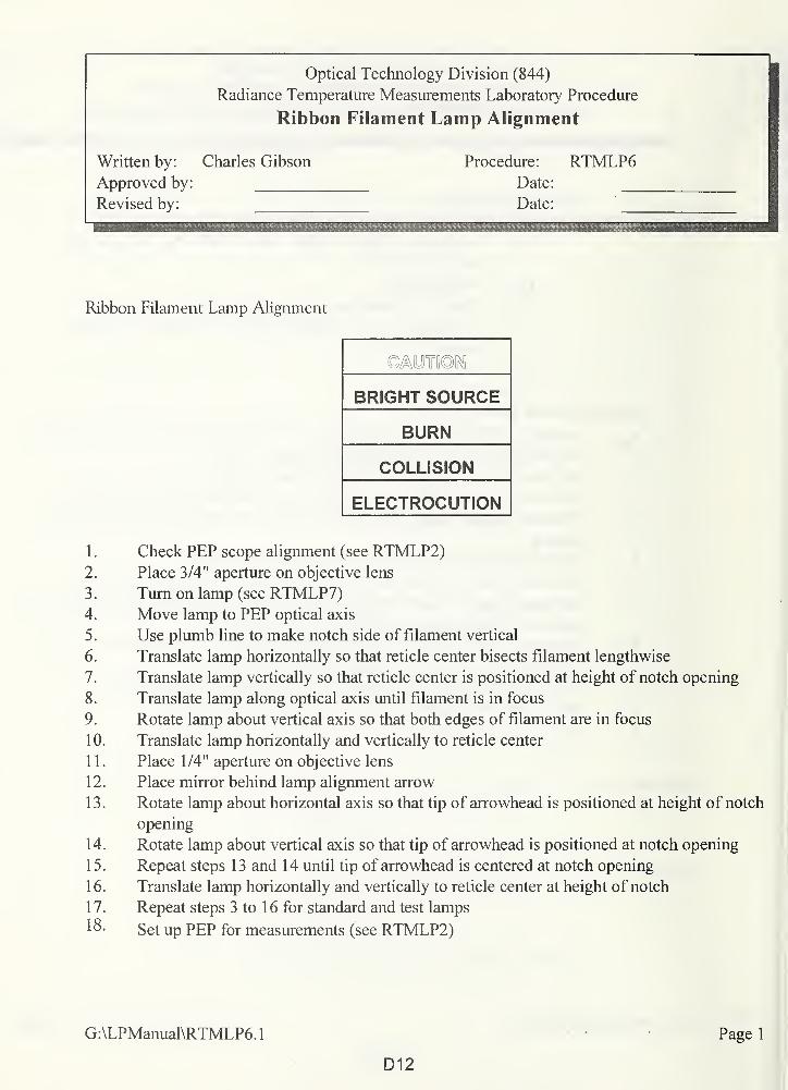
Optical Technology Division (844)
Radiance Temperature Measurements Laboratory Procedure
Ribbon Filament Lamp Alignment
Written by: Charles Gibson Procedure: RTMLP6Approved by: Date:
Revised by: Date:
Ribbon Filament Lamp Alignment
BRIGHT SOURCE
BURN
COLLISION
ELECTROCUTION
1 . Check PEP scope alignment (see RTMLP2)2. Place 3/4" aperture on objective lens
3. Turn on lamp (see RTMLP7)4. Move lamp to PEP optical axis
5. Use plumb line to make notch side of filament vertical
6. Translate lamp horizontally so that reticle center bisects filament lengthwise
7. Translate lamp vertically so that reticle center is positioned at height of notch opening
8. Translate lamp along optical axis until filament is in focus
9. Rotate lamp about vertical axis so that both edges of filament are in focus
10. Translate lamp horizontally and vertically to reticle center
1 1 . Place 1/4" aperture on objective lens
12. Place mirror behind lamp alignment arrow
13. Rotate lamp about horizontal axis so that tip of arrowhead is positioned at height of notch
opening
14. Rotate lamp about vertical axis so that tip of arrowhead is positioned at notch opening
15. Repeat steps 13 and 14 until tip of arrowhead is centered at notch opening
16. Translate lamp horizontally and vertically to reticle center at height of notch
17. Repeat steps 3 to 16 for standard and test lamps
18- Set up PEP for measurements (see RTMLP2)
G:\LPManual\RTMLP6.
1
D12
Page 1
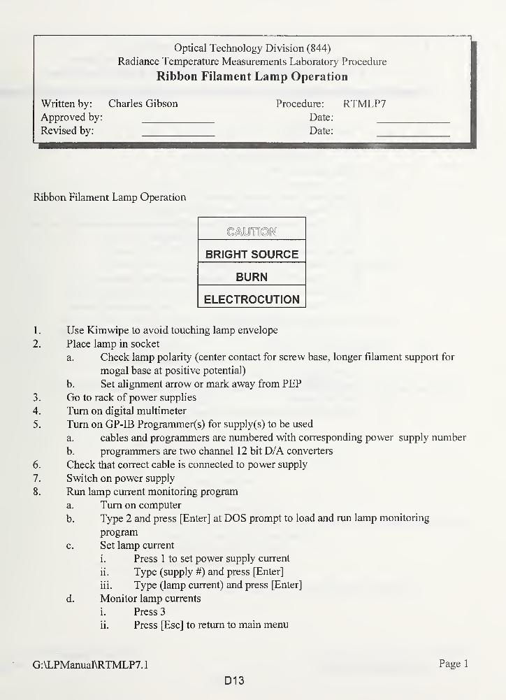
Optical Technology Division (844)
Radiance Temperature Measurements Laboratory Procedure
Ribbon Filament Lamp Operation
Written by: Charles Gibson Procedure: RTMLP7Approved by: Date:
Revised by: Date:
Ribbon Filament Lamp Operation
BRIGHT SOURCE
BURN
ELECTROCUTION
1 . Use Kimwipe to avoid touching lamp envelope
2. Place lamp in socket
a. Check lamp polarity (center contact for screw base, longer filament support for
mogal base at positive potential)
b. Set alignment arrow or mark away from PEP
3. Go to rack of power supplies
4. Turn on digital multimeter
5. Turn on GP-IB Programmer(s) for supply(s) to be used
a. cables and programmers are numbered with corresponding power supply number
b. programmers are two channel 12 bit D/A converters
6. Check that correct cable is connected to power supply
7. Switch on power supply
8. Run lamp current monitoring program
a. Turn on computer
b. Type 2 and press [Enter] at DOS prompt to load and run lamp monitoring
program
c. Set lamp current
i. Press 1 to set power supply current
ii. Type (supply #) and press [Enter]
iii. Type (lamp current) and press [Enter]
d. Monitor lamp currents
i. Press 3
ii. Press [Esc] to return to main menu
G:\LPManual\RTMLP7.
1
D13
Page 1
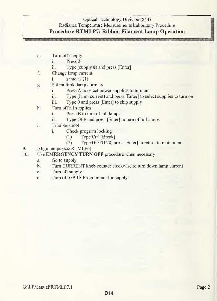
Optical Technology Division (844)
Radiance Temperature Measurements Laboratory Procedure
Procedure RTMLP7: Ribbon Filament Lamp Operation
e. Turn off supply
i. Press 2
ii. Type (supply #) and press [Enter]
f. Change lamp current
i. same as (1)
g. Set multiple lamp currents
i. Press A to select power supplies to turn on
ii. Type (lamp current) and press [Enter] to select supplies to turn on
iii. Type 0 and press [Enter] to skip supply
h. Turn off all supplies
i. Press B to turn off all lamps
ii. Type OFF and press [Enter] to turn off all lamps
i. Trouble-shoot
i. Check program locking
(1) Type Ctrl [Break]
(2) Type GOTO 20, press [Enter] to return to main menu
9. Align lamps (see RTMLP6)1 0. Use EMERGENCY TURN OFF procedure when necessary
a. Go to supply
b. Turn CURRENT knob counter clockwise to turn down lamp current
c. Turn off supply
d. Turn off GP-IB Programmer for supply
G:\LPManual\RTMLP7.
1
D14
Page 2
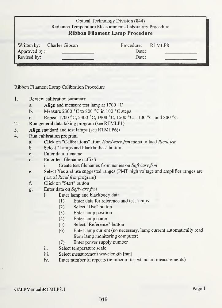
i
Optical Technology Division (844)
Radiance Temperature Measurements Laboratory Procedure
Ribbon Filament Lamp Procedure
Written by: Charles Gibson Procedure: RTMLP8Approved by: Date:
Revised by: Date:
Ribbon Filament Lamp Calibration Procedure
1 . Review calibration summary
a. Align and measure test lamp at 1700 °C
b. Measure 2300 °C to 800 °C in 100 °C steps
c. Repeat 1700 °C, 2300 °C, 1900 °C, 1500 °C, 1 100 °C, and 800 °C
2. Run general data taking program (see RTMLP 1
)
3. Align standard and test lamps (see RTMLP6))
4. Run calibration program
a. Click on "Calibrations" from Hardware.frm menu to load Rtcal.frm
b. Select "Lamps and blackbodies" button
c. Enter data filename
d. Enter test filename suffix$
i. Create test filenames from names on Software.frm
e. Select Yes and use suggested ranges (PMT high voltage and amplifier ranges are
part of Rtcal.frm program)
f. Click on "Start" button
g. Enter data on Software.frm
i. Enter lamp and blackbody data
(1) Enter data for reference and test lamps
(2) Select "Use" button
(3) Enter lamp position
(4) Enter lamp name
(5) Select "Reference" button
(6) Enter lamp current (no necessary, lamp current automatically read
from lamp monitoring computer)
(7) Enter power supply number
ii. Select temperature scale
iii. Select measurement wavelength [nm]
iv. Enter number of repeats (number of test/standard measurements)
G:\LPManual\RTMLP8.
1
D15
Page 1
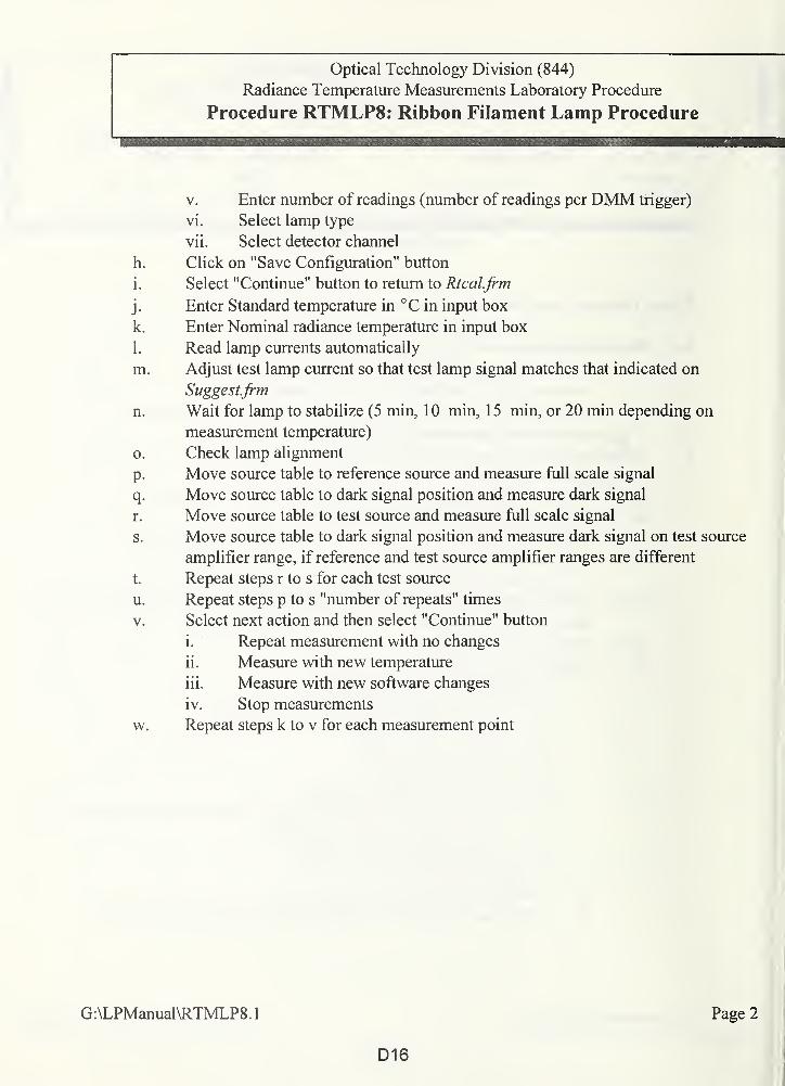
Optical Technology Division (844)
Radiance Temperature Measurements Laboratory Procedure
Procedure RTMLP8: Ribbon Filament Lamp Procedure
v. Enter number of readings (number of readings per DMM trigger)
vi. Select lamp type
vii. Select detector channel
h. Click on "Save Configuration" button
i. Select "Continue" button to return to Rtcal.frm
j. Enter Standard temperature in °C in input box
k. Enter Nominal radiance temperature in input box
1. Read lamp currents automatically
m. Adjust test lamp current so that test lamp signal matches that indicated on
Suggestfrm
n. Wait for lamp to stabilize (5 min, 10 min, 15 min, or 20 min depending on
measurement temperature)
o. Check lamp alignment
p. Move source table to reference source and measure full scale signal
q. Move source table to dark signal position and measure dark signal
r. Move source table to test source and measure full scale signal
s. Move source table to dark signal position and measure dark signal on test source
amplifier range, if reference and test source amplifier ranges are different
t. Repeat steps r to s for each test source
u. Repeat steps p to s "number of repeats" times
v. Select next action and then select "Continue" button
i. Repeat measurement with no changes
ii. Measure with new temperature
iii. Measure with new software changes
iv. Stop measurements
w. Repeat steps k to v for each measurement point
G:\LPManual\RTMLP8.1
D16
Page 2
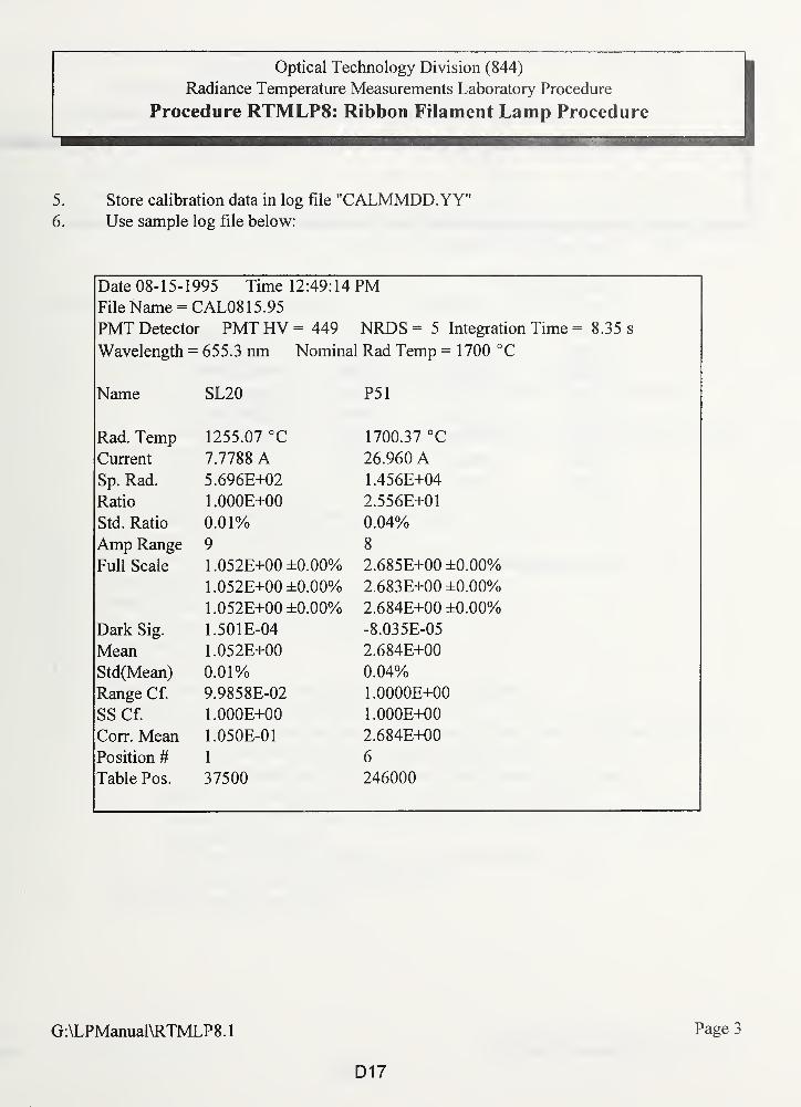
Optical Technology Division (844)
Radiance Temperature Measurements Laboratory Procedure
Procedure RTMLP8: Ribbon Filament Lamp Procedure
5. Store calibration data in log file "CALMMDD.YY'6. Use sample log file below:
Date 08-15-1995 Time 12:49:14 PMFile Name = CAL08 15.95
PMT Detector PMTHV= 449 NRDS = 5 Integration Time = 8.35 s
Wavelength = 655.3 nm Nominal Rad Temp = 1700 °C
Name SL20 P51
Rad. Temp 1255.07 °C 1700.37 °C
Current 7.7788 A 26.960 ASp. Rad. 5.696E+02 1.456E+04
Ratio 1.000E+00 2.556E+01
Std. Ratio 0.01% 0.04%
Amp Range 9 8
Full Scale 1.052E+00 ±0.00% 2.685E+00 ±0.00%
1.052E+00 ±0.00% 2.683E+00 ±0.00%
1.052E+00 ±0.00% 2.684E+00 ±0.00%
Dark Sig. 1.501E-04 -8.035E-05
Mean 1.052E+00 2.684E±00
Std(Mean) 0.01% 0.04%
Range Cf. 9.9858E-02 1.0000E+00
SS Cf. 1.000E+00 1.000E+00
Corr. Mean 1.050E-01 2.684E+00
Position # 1 6
Table Pos. 37500 246000
G:\LPManual\RTMLP8.
1
D17
Page 3
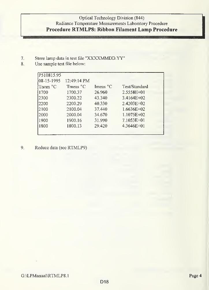
Optical Technology Division (844)
Radiance Temperature Measurements Laboratory Procedure
Procedure RTMLP8: Ribbon Filament Lamp Procedure
7. Store lamp data in test file "XXXXMMDD.YY"8. Use sample test file below:
P510815.95
08-15-1995 12:49:14 PMTnom °C Tmeas °C Imeas °C Test/Standard
1700 1700.37 26.960 2.5558E+01
2300 2300.22 43.340 3.4164E+02
2200 2200.29 40.330 2.4203E+02
2100 2100.04 37.440 1.6636E+02
2000 2000.04 34.670 1.1075E+02
1900 1900.16 31.990 7.1053E+01
1800 1800.13 29.420 4.3646E+01
9. Reduce data (see RTMLP9)
G:\LPManual\RTMLP8.
1
D18
Page 4
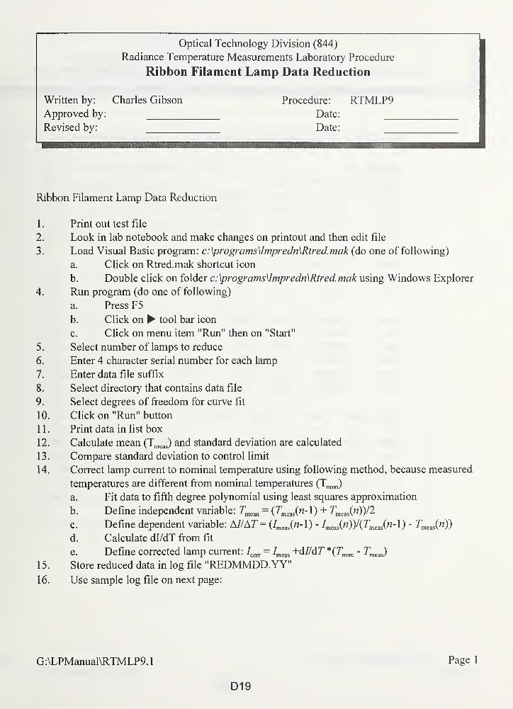
Optical Technology Division (844)
Radiance Temperature Measurements Laboratory Procedure
Ribbon Filament Lamp Data Reduction
Written by: Charles Gibson Procedure: RTMLP9Approved by: Date:
Revised by: Date:
Ribbon Filament Lamp Data Reduction
1 . Print out test file
2. Look in lab notebook and make changes on printout and then edit file
3. Load Visual Basic program: c:\programs\lmpredn\Rtred.mak (do one of following)
a. Click on Rtred.mak shortcut icon
b. Double click on folder c: \programs\lmpredn\Rtred. mak using Windows Explorer
4. Run program (do one of following)
a. Press F5
b. Click on tool bar icon
c. Click on menu item "Run" then on "Start"
5. Select number of lamps to reduce
6. Enter 4 character serial number for each lamp
7. Enter data file suffix
8. Select directory that contains data file
9. Select degrees of freedom for curve fit
10. Click on "Run" button
1 1 . Print data in list box
12. Calculate mean (Tmeas) and standard deviation are calculated
13. Compare standard deviation to control limit
14. Correct lamp current to nominal temperature using following method, because measured
temperatures are different from nominal temperatures (Tnom)
a. Fit data to fifth degree polynomial using least squares approximation
b. Define independent variable: Tmean = {TmeJn-\) + Tmeas(n))/2
c. Define dependent variable: M/AT= (7meas(«-l) - Imea£n))/(Tme:iS(n-\) - Tmeas(n))
d. Calculate dl/dT from fit
e. Define corrected lamp current: IC0TT
= Imeas +o7/dr *(Tmm - Tmeas)1 5 . Store reduced data in log file "REDMMDD.YY"16. Use sample log file on next page:
G:\LPManual\RTMLP9.
1
D19
Page 1
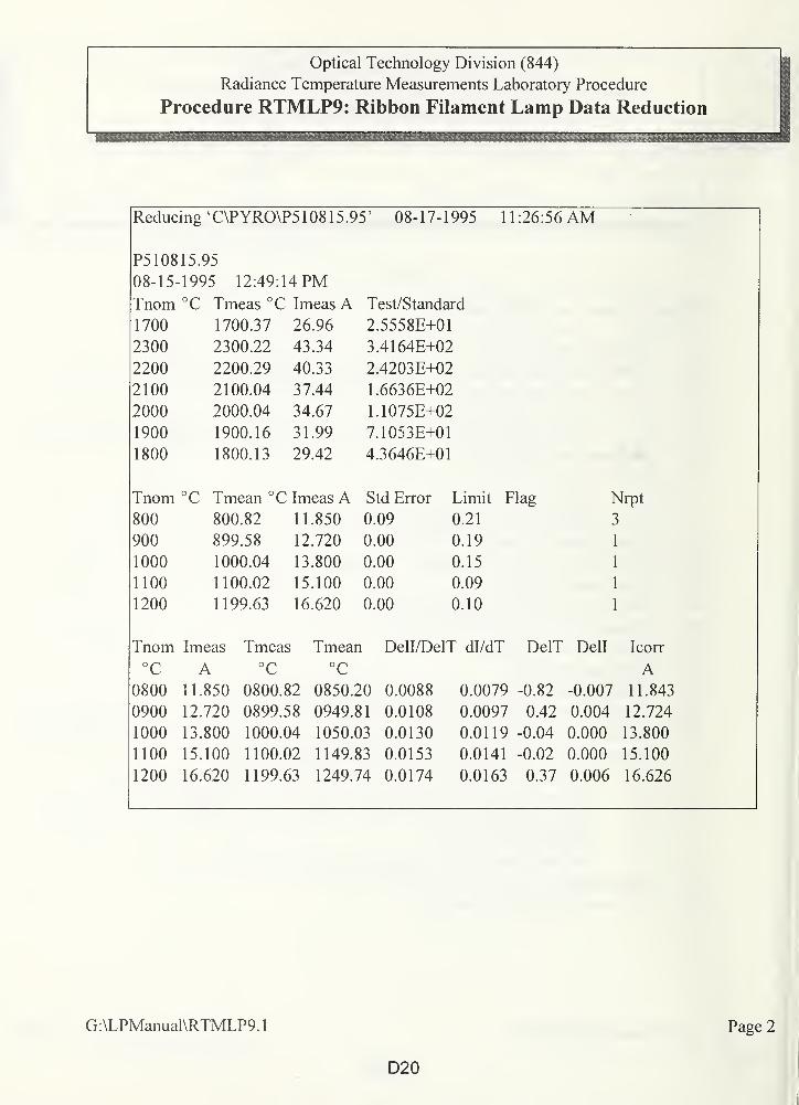
Optical Technology Division (844)
Radiance Temperature Measurements Laboratory Procedure
Procedure RTMLP9: Ribbon Filament Lamp Data Reduction
Reducing 'C\PYRO\P5 108 15.95' 08-17-1995 11:26:56 AM
P510815.95
08-15-1995 12:49:14 PMi nom c Tmeas °C Imeas A Test/Standard
1700 1700.37 26.96 2.5558E+01
2300 2300.22 43.34 3.4164E+02
2200 2200.29 40.33 2.4203E+02
2100 2100.04 37.44 1.6636E+02
2000 2000.04 34.67 1.1075E+02
1900 1900.16 31.99 7.1053E+01
1800 1800.13 29.42 4.3646E+01
Tnom °C Tmean °C Imeas A Std Error Limit Flag Nrpt
800 800.82 11.850 0.09 0.21 3
900 899.58 12.720 0.00 0.19 1
1000 1000.04 13.800 0.00 0.15 1
1100 1100.02 15.100 0.00 0.09 1
1200 1199.63 16.620 0.00 0.10 1
Tnom Imeas Tmeas Tmean Dell/DelT dl/dT DelT Dell Icorr
°C
0800
0900
1000
1100
1200
A11.850
12.720
13.800
15.100
16.620
°C
0800.82
0899.58
1000.04
1100.02
1199.63
°C
0850.20
0949.81
1050.03
1149.83
1249.74
0.0088
0.0108
0.0130
0.0153
0.0174
0.0079 -0.82
0.0097 0.42
0.0119 -0.04
0.0141 -0.02
0.0163 0.37
-0.007
0.004
0.000
0.000
0.006
A11.843
12.724
13.800
15.100
16.626
G:\LPManual\RTMLP9.
1
D20
Page 2
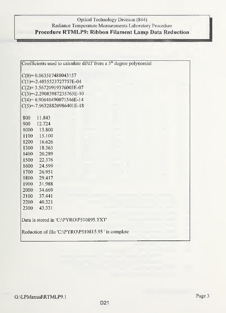
Optical Technology Division (844)
Radiance Temperature Measurements Laboratory Procedure
Procedure RTMLP9: Ribbon Filament Lamp Data Reduction
Coefficients used to calculate d//d!T from a 5thdegree polynomial
C(0)- U.UoJ j 1 /4ooU4J 1 j /
C(l)- O A AT £ CT5 "7T7'7£'7T? A/1-Z.40J jjzj /z / /j /b-U4
C(2)- i.jo/zoyiyj /ouiob-u/
C(3)- -z.2908398 /z3j /ojb-10/""V A \C(4)- 6.906464900/ 1 j4ob-14
C(5)- T A/Ci 1 OOO AAQ/C/1 A 1 f 10- /.963z88z0yoo4U 1 b- 1
5
OAA800 11 O A 11 1 .843
AAA900 1 T A12. /z4
1 AAA1000 1 T OAA13.8001 1 AA1 100 1 C 1 AA
1 j. 100
1200 16.626
1300 18.363
1400 20.289
1500 22.376
1600 24.599
1700 26.951
1800 29.417
1900 31.988
2000 34.669
2100 37.441
2200 40.321
2300 43.331
Data is stored in 'C:\PYRO\P510895.TXT'
Reduction of file 'C:\PYRO\P5 108 15.95 * is complete
G:\LPManual\RTMLP9.1
D21
Page 3
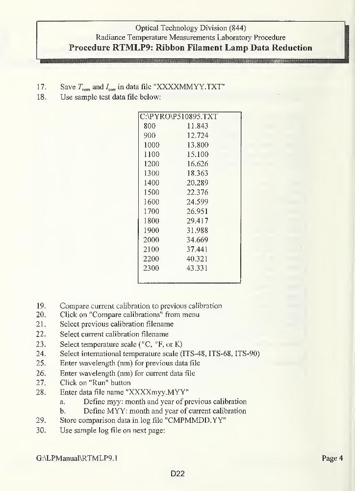
Optical Technology Division (844)
Radiance Temperature Measurements Laboratory Procedure
Procedure RTMLP9: Ribbon Filament Lamp Data Reduction
1 7. Save Tnom and /corT
in data file "XXXXMMYY.TXT"18. Use sample test data file below:
C:\PYRO\P510895.TXT
800 11.843
900 12.724
1000 13.800
1100 15.100
1200 16.626
1300 18.363
1400 20.289
1500 22.376
1600 24.599
1700 26.951
1800 29.417
1900 31.988
2000 34.669
2100 37.441
2200 40.321
2300 43.331
19.
20.
21.
22.
23.
24.
25.
26.
27.
28.
29.
30.
Compare current calibration to previous calibration
Click on "Compare calibrations" from menu
Select previous calibration filename
Select current calibration filename
Select temperature scale (°C, °F, or K)
Select international temperature scale (ITS-48, ITS-68, ITS-90)
Enter wavelength (nm) for previous data file
Enter wavelength (nm) for current data file
Click on "Run" button
Enter data file name "XXXXmyy.MYY"a. Define myy: month and year of previous calibration
b. Define MYY: month and year of current calibration
Store comparison data in log file "CMPMMDD.YY"Use sample log file on next page:
G:\LPManual\RTMLP9.
1
Page 4
D22
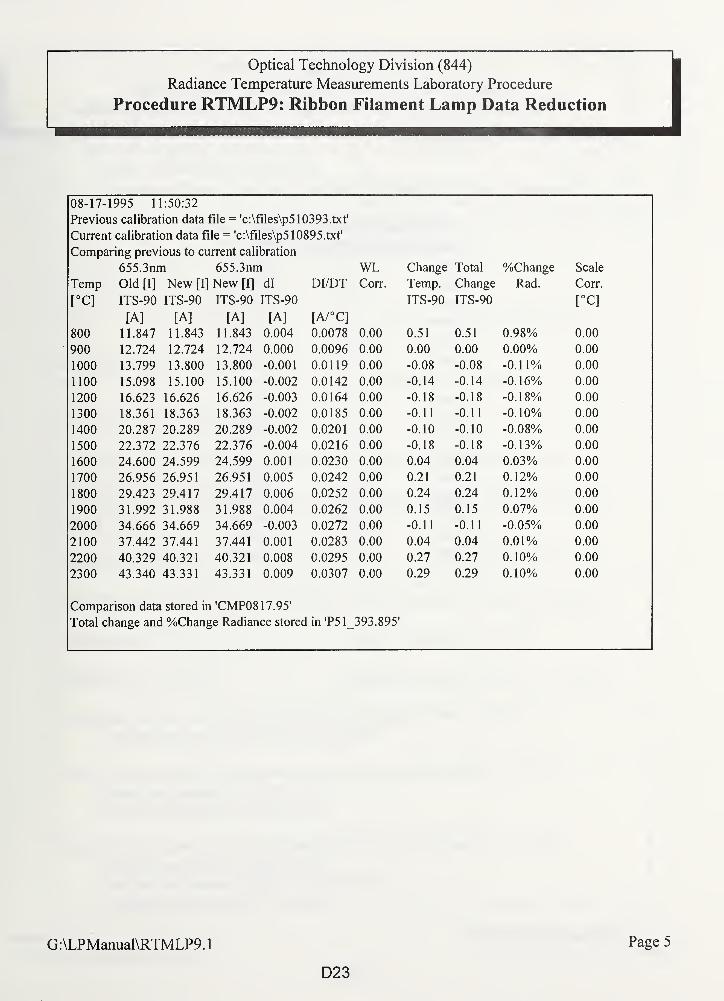
Optical Technology Division (844)
Radiance Temperature Measurements Laboratory Procedure
Procedure RTMLP9: Ribbon Filament Lamp Data Reduction
08-17-1995 11:50:32
Previous calibration data file = 'c:\files\p510393.txt'
Current calibration data file = 'c:\files\p510895.txt'
Comparing previous to current calibration
655.3nm 655.3nm WL Change Total %Change Scale
Temp Old [I] New [I] New [I] dl DI/DT Corr. Temp. Change Rad. Corr.
[°C]L JITS-90 ITS-90 ITS-90 ITS-90 ITS-90 ITS-90 [°C]
[A] [A] [A] [A] [A/°C]
800 11.847 11.843 11.843 0.004 0.0078 0.00 0.51 0.51 0.98% 0.00
900 12.724 12.724 12.724 0.000 0.0096 0.00 0.00 0.00 0.00% 0.00
1000 13.799 13.800 13.800 -0.001 0.0119 0.00 -0.08 -0.08 -0.11% 0.00
1100 15.098 15.100 15.100 -0.002 0.0142 n fin -0.14 -0.14 -U. 10/0 n nou.uu
1200 16.623 16.626 16.626 -0.003 0.0164 0.00 -0.18 -0.18 -0.18% 0.00
1300 18.361 18.363 18.363 -0.002 0.0185 0.00 -0.11 -0.11 -0.10% 0.00
1400 20.287 20.289 20.289 -0.002 0.0201 0.00 -0.10 -0.10 -0.08% 0.00
1500 22.372 22.376 22.376 -0.004 0.0216 0.00 -0.18 -0.18 -0.13% 0.00
1600 24.600 24.599 24.599 0.001 0.0230 0.00 0.04 0.04 0.03% 0.00
1700 26.956 26.951 26.951 0.005 0.0242 0.00 0.21 0.21 0.12% 0.00
1800 29.423 29.417 29.417 0.006 0.0252 0.00 0.24 0.24 0.12% 0.00
1900 31.992 31.988 31.988 0.004 0.0262 0.00 0.15 0.15 0.07% 0.00
2000 34.666 34.669 34.669 -0.003 0.0272 0.00 -0.11 -0.11 -0.05% 0.00
2100 37.442 37.441 37.441 0.001 0.0283 0.00 0.04 0.04 0.01% 0.00
2200 40.329 40.321 40.321 0.008 0.0295 0.00 0.27 0.27 0.10% 0.00
2300 43.340 43.331 43.331 0.009 0.0307 0.00 0.29 0.29 0.10% 0.00
Comparison data stored in 'CMP08 17.95'
Total change and %Change Radiance stored in 'P51 393.895'
G:\LPManual\RTMLP9.
1
D23
Page 5
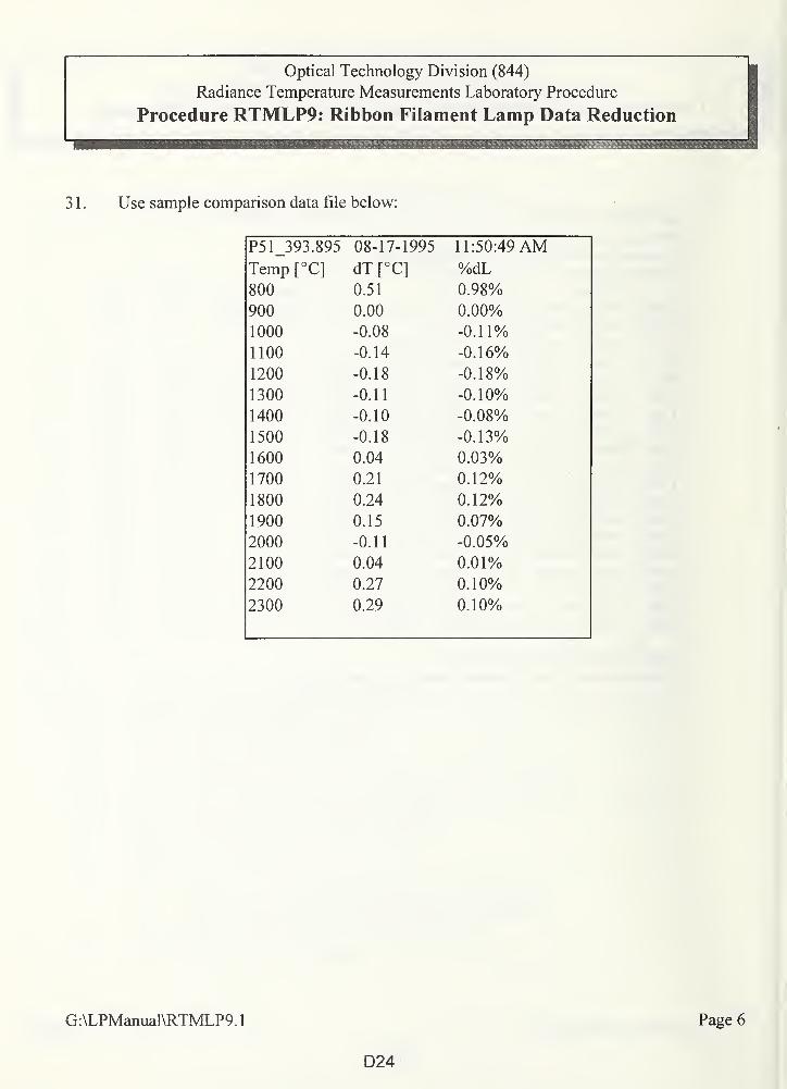
Optical Technology Division (844)
Radiance Temperature Measurements Laboratory Procedure
Procedure RTMLP9: Ribbon Filament Lamp Data Reduction
3 1 . Use sample comparison data file below:
P51_393.895 08-17-1995 11:50:49 AMTemp [°C]
x L JdT [°C] %dL
800 0.51 0.98%
900 0.00 0.00%
1000 -0.08 -0.11%
1100 -0.14 -0.16%
1200 -0.18 -0.18%
1300 -0.11 -0.10%
1400 -0.10 -0.08%
1500 -0.18 -0.13%
1600 0.04 0.03%
1700 0.21 0.12%
1800 0.24 0.12%
1900 0.15 0.07%
2000 -0.11 -0.05%
2100 0.04 0.01%
2200 0.27 0.10%
2300 0.29 0.10%
G:\LPManual\RTMLP9.1
D24
Page 6
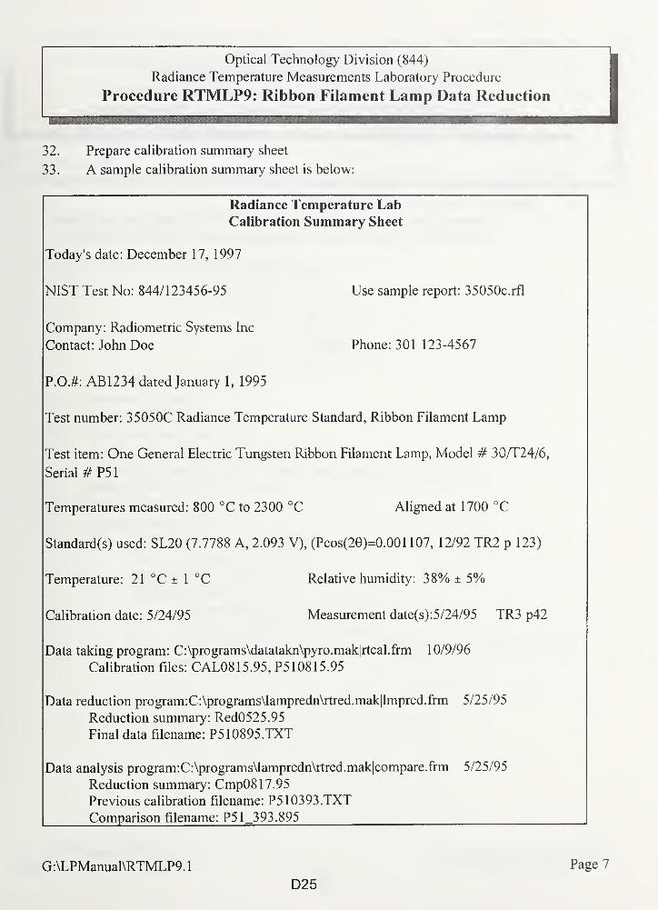
Optical Technology Division (844)
Radiance Temperature Measurements Laboratory Procedure
Procedure RTMLP9: Ribbon Filament Lamp Data Reduction
32. Prepare calibration summary sheet
33. A sample calibration summary sheet is below:
Radiance Temperature LabCalibration Summary Sheet
Today's date: December 17, 1997
NIST Test No: 844/123456-95 Use sample report: 35050c.rfl
Company: Radiometric Systems Inc
Contact: John Doe Phone: 301 123-4567
P.O.#: AB1234 dated January 1, 1995
Test number: 35050C Radiance Temperature Standard, Ribbon Filament Lamp
Test item: One General Electric Tungsten Ribbon Filament Lamp, Model # 30/T24/6,
Serial # P51
Temperatures measured: 800 °C to 2300 °C Aligned at 1700 °C
Standard(s) used: SL20 (7.7788 A, 2.093 V), (Pcos(20)=0.001 107, 12/92 TR2 p 123)
Temperature: 21 °C ± 1 °C Relative humidity: 38% ± 5%
Calibration date: 5/24/95 Measurement date(s): 5/24/95 TR3 p42
Data taking program: C:\programs\datatakn\pyro.mak|rtcal.frm 10/9/96
Calibration files: CAL0815.95, P510815.95
Data reduction program:C:\programs\lampredn\rtred.mak|lmpred.frm 5/25/95
Reduction summary: Red0525.95
Final data filename: P510895.TXT
Data analysis program:C:\programs\lampredn\rtred.mak|compare.frm 5/25/95
Reduction summary: Cmp08 17.95
Previous calibration filename: P510393.TXT
Comparison filename: P51_393.895
G:\LPManual\RTMLP9.1
D25
Page 7
Optical Technology Division (844)
Radiance Temperature Measurements Laboratory Procedure
Procedure RTMLP9: Ribbon Filament Lamp Data Reduction
34. Enter data file name "XXXXmyy.MYY"a. Prepare history file consisting of Microsoft EXCEL spreadsheet with plots of
temperature difference from first calibration versus nominal temperature
G:\LPManual\RTMLP9.1
D26
Page 8
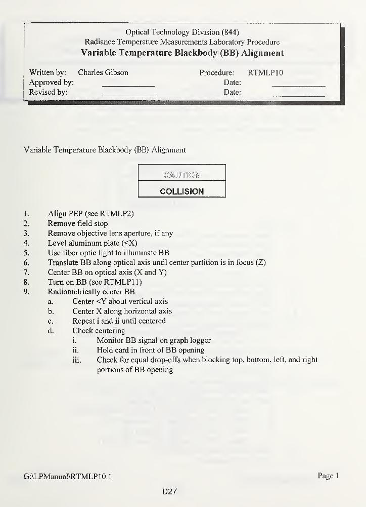
_—Optical Technology Division (844)
Radiance Temperature Measurements Laboratory Procedure
Variable Temperature Blackbody (BB) Alignment
Written by: Charles Gibson Procedure: RTMLP10Approved by: Date:
Revised by: Date:
Variable Temperature Blackbody (BB) Alignment
COLLISION
1. Align PEP (see RTMLP2)2. Remove field stop
3. Remove objective lens aperture, if any
4. Level aluminum plate (<X)
5. Use fiber optic light to illuminate BB6. Translate BB along optical axis until center partition is in focus (Z)
7. Center BB on optical axis (X and Y)
8. Turn on BB (see RTMLP 1 1
)
9. Radiometrically center BBa. Center <Y about vertical axis
b. Center X along horizontal axis
c. Repeat i and ii until centered
d. Check centering
i. Monitor BB signal on graph logger
ii. Hold card in front of BB opening
iii. Check for equal drop-offs when blocking top, bottom, left, and right
portions ofBB opening
G:\LPManual\RTMLP 1 0.
1
D27
Page 1
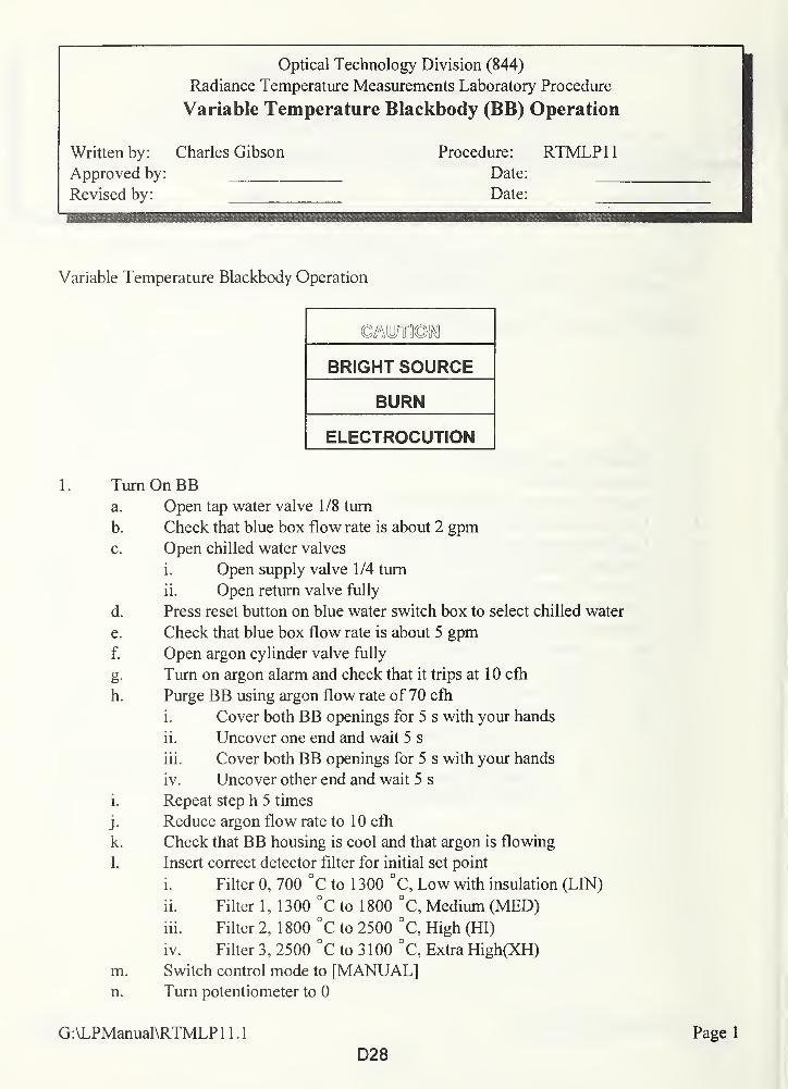
Optical Technology Division (844)
Radiance Temperature Measurements Laboratory Procedure
Variable Temperature Blackbody (BB) Operation
Written by: Charles Gibson Procedure: RTMLP11Approved by: Date:
Revised by: Date:
Variable Temperature Blackbody Operation
BRIGHT SOURCE
BURN
ELECTROCUTION
1. Turn On BBa. Open tap water valve 1/8 turn
b. Check that blue box flow rate is about 2 gpmc. Open chilled water valves
i. Open supply valve 1/4 turn
ii. Open return valve fully
d. Press reset button on blue water switch box to select chilled water
e. Check that blue box flow rate is about 5 gpmf. Open argon cylinder valve fully
g. Turn on argon alarm and check that it trips at 10 cfh
h. Purge BB using argon flow rate of 70 cfh
i. Cover both BB openings for 5 s with your hands
ii. Uncover one end and wait 5 s
iii. Cover both BB openings for 5 s with your hands
iv. Uncover other end and wait 5 s
i. Repeat step h 5 times
j . Reduce argon flow rate to 1 0 cfh
k. Check that BB housing is cool and that argon is flowing
1. Insert correct detector filter for initial set point
i. Filter 0, 700 °C to 1 300 °C, Low with insulation (LIN)
ii. Filter 1 , 1 300 °C to 1 800 °C, Medium (MED)
iii. Filter 2, 1 800 °C to 2500 °C, High (HI)
iv. Filter 3, 2500 °C to 3100 °C, Extra High(XH)
m. Switch control mode to [MANUAL]n. Turn potentiometer to 0
G:\LPManual\RTMLPl 1 . 1 Page 1
D28
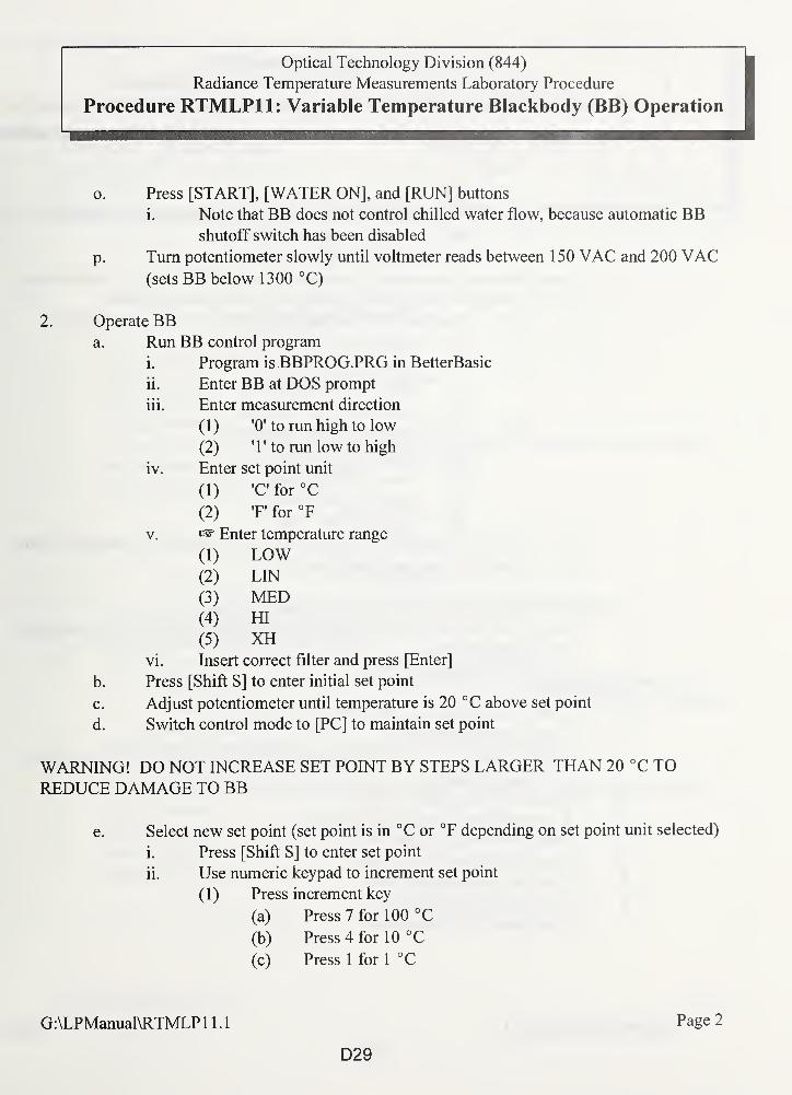
Optical Technology Division (844)
Radiance Temperature Measurements Laboratory Procedure
Procedure RTMLP11: Variable Temperature Blackbody (BB) Operation
Press [START], [WATER ON], and [RUN] buttons
i. Note that BB does not control chilled water flow, because automatic BBshutoff switch has been disabled
Turn potentiometer slowly until voltmeter reads between 150 VAC and 200 VAC(sets BB below 1300 °C)
2. Operate BBa. Run BB control program
i. Program is BBPROG.PRG in BetterBasic
ii. Enter BB at DOS prompt
iii. Enter measurement direction
(1) '0' to run high to low
(2) T to run low to high
iv. Enter set point unit
(1) 'C for °C
(2) T* for °F
v. Enter temperature range
(1) LOW(2) LIN
(3) MED(4) HI
(5) XHvi. Insert correct filter and press [Enter]
b. Press [Shift S] to enter initial set point
c. Adjust potentiometer until temperature is 20 °C above set point
d. Switch control mode to [PC] to maintain set point
WARNING! DO NOT INCREASE SET POINT BY STEPS LARGER THAN 20 °C TOREDUCE DAMAGE TO BB
e. Select new set point (set point is in °C or °F depending on set point unit selected)
i. Press [Shift S] to enter set point
ii. Use numeric keypad to increment set point
(1) Press increment key
(a) Press 7 for 100 °C
(b) Press 4 for 10 °C
(c) Press 1 for 1 °C
o.
P-
G:\LPManual\RTMLP 11.1
D29
Page 2
Optical Technology Division (844)
Radiance Temperature Measurements Laboratory Procedure
Procedure RTMLP11: Variable Temperature Blackbody (BB) Operation
(d) Press 0 for 0.1 °C
(2) Press direction key to set new set point
(a) Press 8 to increase set point
(b) Press 2 to decrease set point
f. Pause program (suspending BB control) if new set point is not in current range
i. Use default set points depending on measurement direction
(1 ) Use high to low default set points
(a) Select XH for 2500 °C
(b) Select HI for 2300 °C
(c) Select MED for 1800 °C
(d) Select LOW for 1300 °C
(2) Use low to high default set points
(a) Select LOW for 800 °C
(b) Select MED for 1300 °C
(c) Select HI for 1800 °C
(d) Select XH for 2500 °C
ii. Switch control mode to [MANUAL] if new set point is not default value
iii. Loop program step 2.a.v. (see
3 . Use EMERGENCY TURN OFF procedure when necessary
a. Press [EMERGENCY STOP] button on power supply (chilled water and argon
will continue flowing)
b. Continue with steps 4.b. to 4.j.
4. Turn OffBBa. Switch control mode to [MANUAL]b. Turn to potentiometer to 0
c. Press [EMERGENCY STOP] button on power supply (chilled water and argon
will continue flowing)
d. Switch off main breaker on wall
e. Wait until furnace has stopped glowing
f. Close chilled water supply valve
g. Close chilled water return valve
h. Close cold water supply valve
i. Close argon cylinder valve
j . Close argon flow meter valve
G:\LPManual\RTMLP 11.1
D30
Page 3
Optical Technology Division (844)
Radiance Temperature Measurements Laboratory Procedure
Disappearing Filament Optical Pyrometer Alignment
Written by: Charles Gibson Procedure: RTMLP12Approved by: Date:
Revised by: Date:
Disappearing Filament Optical Pyrometer Alignment
1. Align BB (see RTMLP 10)
2. Check that objective lens and eye piece are clean
3. Check batteries
4. Zero galvanometer
5. Use post with magnetic base, height adjustment, and angle bracket to mount pyrometer
6. Position post and level angle bracket mounting surface
7. Mount pyrometer to angle bracket
COLLISION
8. Use joystick to move BB to test pyrometer position
9. Use fiber optic light to illuminate BB10. Set pyrometer at measuring distance from BB center partition
a. Use distance of 30.2 cm from center partition to end of graphite extension tube
b. Measure distance from front surface of objective lens holder to extension tube (for
1 m, distance is 69.8 cm)
1 1 . Adjust pyrometer eye piece to focus on illuminated lamp filament
12. Focus pyrometer on center partition
13. Adjust pyrometer and/or move BB so that pyrometer views down center ofBB cavity
14. Check distance
15. Adjust pyrometer and/or move BB so that pyrometer views down center of BB cavity
16. Record table position
1 7. Repeat for other test pyrometers
G:\LPManual\RTMLP12.1 Page 1
D31
Optical Technology Division (844)
Radiance Temperature Measurements Laboratory Procedure
Radiation Thermometer (RT) Alignment
Written by:
Approved by:
Revised by:
Charles Gibson Procedure: RTMLP13Date:
Date:
Radiation Thermometer (RT) Alignment
1. Align BB (see RTMLP 10)
2. Check that objective lens and eye piece are clean
3. Use post with magnetic base, height adjustment, and angle bracket to mount RT4. Position post and level angle bracket mounting surface
5. Mount RT to angle bracket
COLLISION
6. Use joystick to move BB to test RT position
7. Use fiber optic light to illuminate BB8. Set RT at measuring distance from BB center partition
a. Use distance of 30.2 cm from center partition to end of graphite extension tube
b. Measure distance from front surface of objective lens holder to extension tube (for
1 m, distance is 69.8 cm)
c. Measure distance from alignment mark to extension tube for Land Cyclops RT(for 1 m, distance is 69.8 cm)
9. Adjust RT eye piece to operator's eye
1 0. Focus RT on center partition
1 1 . Adjust RT and/or move BB so that RT views down center ofBB cavity
12. Check distance
13. Adjust RT and/or move BB so that RT views down center ofBB cavity
14. Record table position
15. Repeat steps 2 to 14 for each test RT1 6. Turn on BB (see RTMLP 1 1
)
17. Check centering of each test RTa. Monitor RT signal on graph logger or look at RT display panel
b. Hold card in front ofBB opening
c. Check for equal drop-offs when blocking top, bottom, left, and right portions of
BB opening
G:\LPManual\RTMLP13.1 Page 1
D32
Optical Technology Division (844)1
Radiance Temperature Measurements Laboratory Procedure
Radiation Thermometer (Optical Pyrometer)
Calibration Procedure
Written by: Charles Gibson Procedure: RTMLP14Approved by: Date:
Revised by: Dale:
!
Radiation Thermometer (Optical Pyrometer) Calibration Procedure
1 . Review calibration summary
a. Align standard lamp, BB, and test RTS
b. Measure from 2700 °C to 800 °C in 100 °C steps
c. Repeat 2300 °C, 1900 °C, 1500 °C, 1300 °C, 1 100 °C, and 800 °C
2. Run general data taking program (see RTMLP1)
3. Align standard lamp (see RTMLP6)
4. Align BB (see RTMLP 10)
5. Align RTS (see RTMLP 13)
6. Run calibration program
a. Click on "Calibrations" from Hardware.frm menu to load Rtcal.frm
b. Select "Radiation thermometer" button
c. Enter data filename
d. Enter test filename suffix$
i. Create test filenames from names on Software.frm
e. Select Yes and use suggested ranges (PMT high voltage and amplifier ranges are
part of Rtcal.frm program)
f. Click on "Start" button
g. Enter data on Software.frm
i. Enter lamp and blackbody data
(1) Enter data for reference and BB(2) Select "Use" button
(3) Enter lamp position
(4) Enter lamp name
(5) Select "Reference" button
(6) Enter lamp current (not necessary because lamp currents are
automatically read from lamp monitoring computer)
(7) Enter power supply number
G:\LPManual\RTMLP14.
1
D33
Page 1
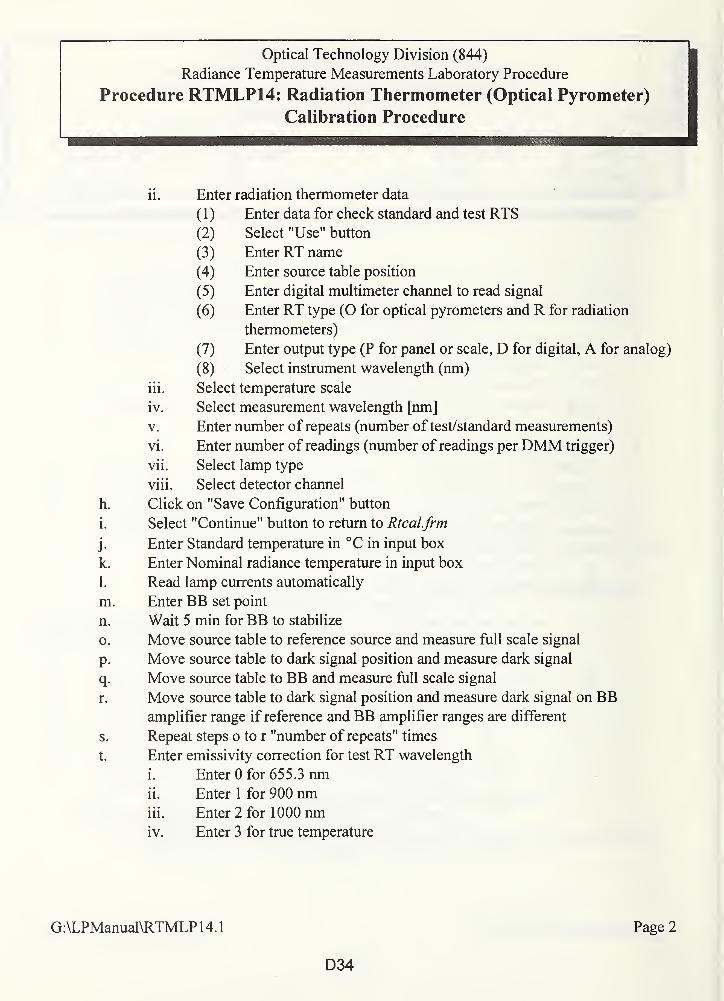
Optical Technology Division (844)
Radiance Temperature Measurements Laboratory Procedure
Procedure RTMLP14: Radiation Thermometer (Optical Pyrometer)
Calibration Procedure
ii. Enter radiation thermometer data
(1) Enter data for check standard and test RTS
(2) Select "Use" button
(3) Enter RT name
(4) Enter source table position
(5) Enter digital multimeter channel to read signal
(6) Enter RT type (0 for optical pyrometers and R for radiation
thermometers)
(7) Enter output type (P for panel or scale, D for digital, A for analog)
(8) Select instrument wavelength (nm)
iii. Select temperature scale
iv. Select measurement wavelength [nm]
v. Enter number of repeats (number of test/standard measurements)
vi. Enter number of readings (number of readings per DMM trigger)
vii. Select lamp type
viii. Select detector channel
h. Click on "Save Configuration" button
i. Select "Continue" button to return to Rtcal.frm
j. Enter Standard temperature in °C in input box
k. Enter Nominal radiance temperature in input box
1. Read lamp currents automatically
m. Enter BB set point
n. Wait 5 min for BB to stabilize
o. Move source table to reference source and measure full scale signal
p. Move source table to dark signal position and measure dark signal
q. Move source table to BB and measure full scale signal
r. Move source table to dark signal position and measure dark signal on BBamplifier range if reference and BB amplifier ranges are different
s. Repeat steps o to r "number of repeats" times
t. Enter emissivity correction for test RT wavelength
i. Enter 0 for 655.3 nmii. Enter 1 for 900 nmiii. Enter 2 for 1 000 nmiv. Enter 3 for true temperature
G:\LPManual\RTMLP 14.1 Page 2
D34
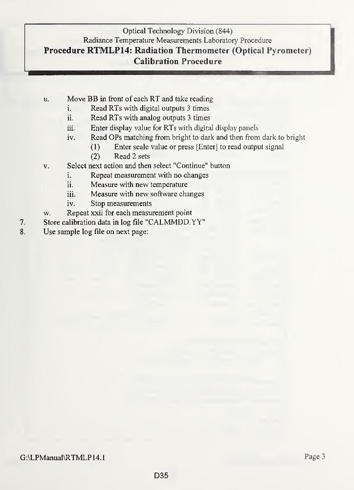
Optical Technology Division (844)
Radiance Temperature Measurements Laboratory Procedure
Procedure RTMLP14: Radiation Thermometer (Optical Pyrometer)
Calibration Procedure
u. Move BB in front of each RT and take reading
i. Read RTs with digital outputs 3 times
ii. Read RTs with analog outputs 3 times
iii. Enter display value for RTs with digital display panels
iv. Read OPs matching from bright to dark and then from dark to bright
(1) Enter scale value or press [Enter] to read output signal
(2) Read 2 sets
v. Select next action and then select "Continue" button
i. Repeat measurement with no changes
ii. Measure with new temperature
iii. Measure with new software changes
iv. Stop measurements
w. Repeat xxii for each measurement point
7. Store calibration data in log file "CALMMDD.YY"8. Use sample log file on next page:
G:\LPManual\RTMLP 14.1
D35
Page 3
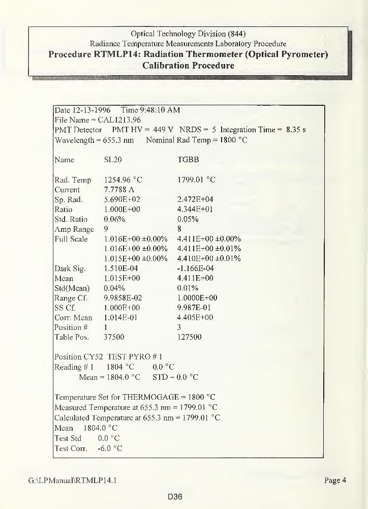
Optical Technology Division (844)
Radiance Temperature Measurements Laboratory Procedure
Procedure RTMLP14: Radiation Thermometer (Optical Pyrometer)
Calibration Procedure——
^b MM—
Date 12-13- 1996 Time 9:48:10 AMFile Name = CAL1213.96
PMT Detector PMT HV - 449 V NRDS = 5 Integration Time = 8.35 s
Wavelength = 655.3 nm Nominal Rad Temp = 1800 °C
Name SL20 TGBB
Rad. Temp 1254.96 °C 1799.01 °C
Current 7.7788 ASp. Rad. 5.690E+02 2.472E+04
Ratio 1.000E+00 4.344E+01
Std. Ratio 0.06% 0.05%
Amp Range 9 8
Full Scale 1.016E+00 ±0.00% 4.411E+00 ±0.00%
1.016E+00 ±0.00% 4.411E+00 ±0.01%
1.015E+00 ±0.00% 4.410E±00 ±0.01%
Dark Sig. 1.510E-04 -1.166E-04
Mean 1.015E+00 4.411E+00
Std(Mean) 0.04% 0.01%
Range Cf. 9.9858E-02 1.0000E+00
SS Cf. 1.000E+00 9.987E-01
Corr. Mean 1.014E-01 4.405E+00
Position # 1 3
Table Pos. 37500 127500
Position CY52 TEST PYRO # 1
Reading # 1 1804 °C 0.0 °C
Mean = 1804.0 °C STD = 0.0 °C
Temperature Set for THERMOGAGE - 1800 °C
Measured Temperature at 655.3 nm == 1799.01 °C
Calculated Temperature at 655.3 nm = 1799.01 °C
Mean 1804.0 °C
Test Std 0.0 °C
Test Corr. -6.0 °C
G:\LPManual\RTMLP14.1 Page 4
D36
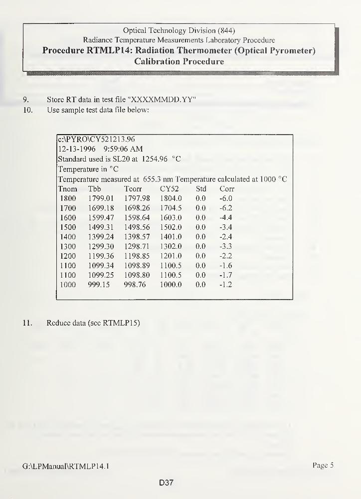
Optical Technology Division (844)
Radiance Temperature Measurements Laboratory Procedure
Procedure RTMLP14: Radiation Thermometer (Optical Pyrometer)
Calibration Procedure
9. Store RT data in test file "XXXXMMDD.YY"10. Use sample test data file below:
c:\PYRO\CY521213.96
12-13-1996 9:59:06 AMStandard used is SL20 at 1254.96 °C
Temperature in °C
Temperature measured at 655.3 nm Temperature calculated at 1000 °C
Tnom Tbb Tcorr CY52 Std Corr
1800 1799.01 1797.98 1804.0 0.0 -6.0
1700 1699.18 1698.26 1704.5 0.0 -6.2
1600 1599.47 1598.64 1603.0 0.0 -4.4
1500 1499.31 1498.56 1502.0 0.0 -3.4
1400 1399.24 1398.57 1401.0 0.0 -2.4
1300 1299.30 1298.71 1302.0 0.0 -3.3
1200 1199.36 1198.85 1201.0 0.0 -2.2
1100 1099.34 1098.89 1100.5 0.0 -1.6
1100 1099.25 1098.80 1100.5 0.0 -1.7
1000 999.15 998.76 1000.0 0.0 -1.2
1 1 . Reduce data (see RTMLP 1 5)
G:\LPManual\RTMLP 14.1
D37
Page 5
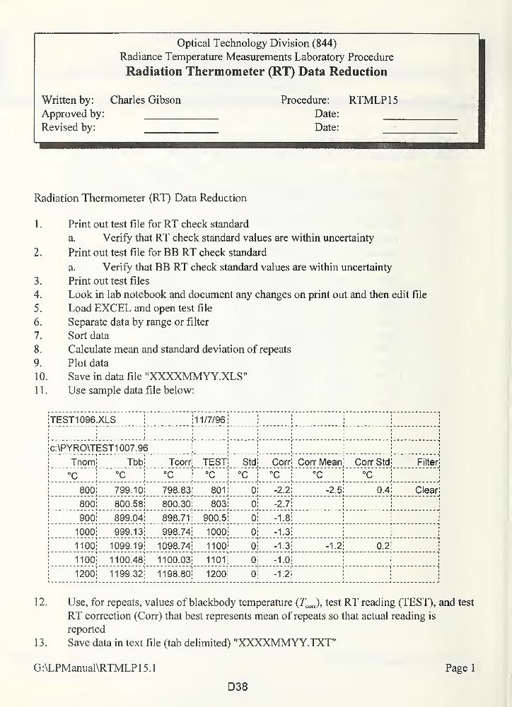
Optical Technology Division (844)
Radiance Temperature Measurements Laboratory Procedure
Radiation Thermometer (RT) Data Reduction
Written by: Charles Gibson
Approved by:
Revised by:
Procedure: RTMLP15Date:
Date:
Radiation Thermometer (RT) Data Reduction
1 . Print out test file for RT check standard
a. Verify that RT check standard values are within uncertainty
2. Print out test file for BB RT check standard
a. Verify that BB RT check standard values are within uncertainty
3. Print out test files
4. Look in lab notebook and document any changes on print out and then edit file
5. Load EXCEL and open test file
6. Separate data by range or filter
7. Sort data
8. Calculate mean and standard deviation of repeats
9. Plot data
10. Save in data file "XXXXMMYY.XLS"1 1 . Use sample data file below:
TEST1096.XLS :11/7/96
c:\PYRO\TEST1007.96
Tnom Tbb Tcorr TEST Std Corr Corr Mean Corr Std Filter
°C °C °C °C °C °C °C °C
800 799.10 798.83 801 0 -2.2 -2.5 0.4 Clear
800 800.58 800.30 803 0 -2.7
900 899.04 898.71 900.5 0 -1.8
1000 999.13 998.74 1000 0 -1.3
1100 1099.19 1098.74 1100 0 -1.3 -1.2 0.2
1100 1100.48 1100.03 1101 0 -1.0
1200 1199.32 1198.80 1200 0 -1.2
12. Use, for repeats, values of blackbody temperature (Tcon), test RT reading (TEST), and test
RT correction (Corr) that best represents mean of repeats so that actual reading is
reported
1 3 . Save data in text file (tab delimited) "XXXXMMYY.TXT"
G:\LPManual\RTMLP 15.1 Page 1
D38
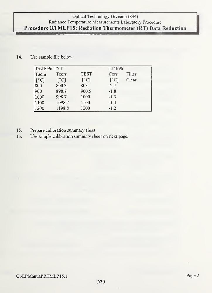
Optical Technology Division (844)
Radiance Temperature Measurements Laboratory Procedure
Procedure RTMLP15: Radiation Thermometer (RT) Data Reduction
14. Use sample file below:
Testl096.TXT 11/4/96
Tnom Tcorr TEST Corr Filter
[°C] E°C] [°C] [°C] Clear
800 800.3 803 -2.7
900 898.7 900.5 -1.8
1000 998.7 1000 -1.3
1100 1098.7 1100 -1.3
1200 1198.8 1200 -1.2
15. Prepare calibration summary sheet
16. Use sample calibration summary sheet on next page:
G:\LPManual\RTMLP 15.1
D39
Page 2
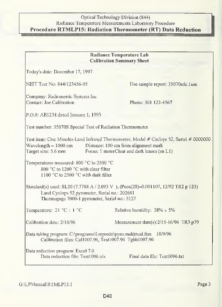
Optical Technology Division (844)
Radiance Temperature Measurements Laboratory Procedure
Procedure RTMLP15: Radiation Thermometer (RT) Data Reduction
Radiance Temperature LabCalibration Summary Sheet
Today's date: December 17, 1997
NIST Test No: 844/123456-95 Use sample report: 35070sdc.lum
Company: Radiometric Systems Inc
Contact: Joe Calibration Phone: 301 123-4567
P.OJ: AB1234 dated January 1, 1995
Test number: 35070S Special Test of Radiation Thermometer
Test item: One Minolta-Land Infrared Thermometer, Model # Cyclops 52, Serial # 0000000
Temperatures measured: 800 °C to 2500 °C
800 °C to 1200 °C with clear filter
1 100 °C to 2500 °C with dark filter
Standard(s) used: SL20 (7.7788 A / 2.093 V ), (Pcos(20)=0.001 107, 12/92 TR2 p 123)
Land Cyclops 52 pyrometer, Serial no.: 202681
Thermogage 7000-1 pyrometer, Serial no.: 5127
Temperature: 21 °C ± 1 °C Relative humidity: 38% ± 5%
Calibration date: 2/16/96 Measurement date(s):2/15-16/96 TR3 p79
Data taking program: C:\programs\Lmpredn\pyro.mak|rtcal.frm 10/9/96
Calibration files: Call007.96, Testl007.96 Tgbbl007.96
Data reduction program: Excel 7.0
Data reduction file: Testl096.xls Final data file: Testl096.txt
G:\LPManual\RTMLP15.1 Page 3
Wavelength = 1000 nmTarget size: 5.6 mm
Distance: 100 cm from alignment mark
Focus: 1 meterClear and dark lenses (sn LI)
D40
Optical Technology Division (844)
Radiance Temperature Measurements Laboratory Procedure
Procedure RTMLP15: Radiation Thermometer (RT) Data Reductioni
17. Print out test file for RT check standard
a. Prepare history file consisting of Microsoft EXCEL spreadsheet with plots of
temperature difference from first calibration versus nominal temperature
G:\LPManual\RTMLP 15.1
D41
Page 4
Appendix E: How to Request Radiance Temperature Measurement Services
1. Prepare a purchase order with the following:
a. Company name and address
b. Contact person's name and phone number.
c. Billing address
d. Service ID number requested (include range and points)
e. Test fee
f. Address to ship test item
g. Return shipping instructions (prepay and add, COD, charge to account with shipper)
i. the test fee does not include shipping costs
ii. customers are responsible for all shipping costs
iii. If no instructions are given, NIST will return the test item by common carrier, collect,
and uninsured.
2. Send the purchase order to:
National Institute of Standards and Technology
Calibration Program
Building 820, Room 232
Gaithersburg, MD 20899-0001
Tel.: (301) 975-2002
FAX: (301) 869-3548
E-mail: [email protected]
3.Send the test item(s) to:
Charles Gibson
NISTBuilding 221 / Room B208Gaithersburg, MD 20899-0001
Tel.: (301)975-2329
FAX: (301)869-5700
E-mail: [email protected]
WWW: http://physics.nist.gov/Divisions/Div844/staff/Gp3/gibson.html
Radiance temperature calibrations are performed in February, May, August, and November.
Requests for calibration services are scheduled after the receipt of a purchase order.
NIST policy requires prepayment of all calibration services performed for non-U.S.
organizations. Please contact the Calibration Program office to arrange payment.
E1
4U.S. GOVERNMENT PRINTING OFFICE: 1998-433-235/93205


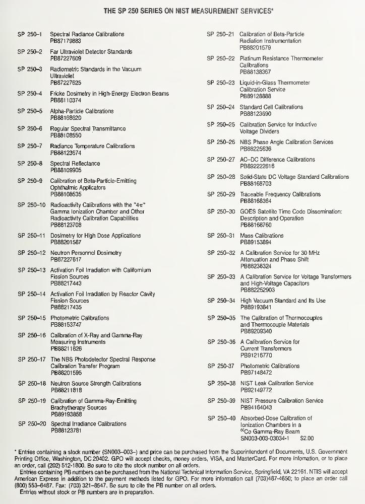
THE SP 250 SERIES ON NIST MEASUREMENT SERVICES*
SP 250-1 Spectral Radiance Calibrations
PB871 79883
SP 250-2 Far Ultraviolet Detector Standards
PB87227609
SP 250-3 Radiometric Standards in the VacuumUltraviolet
PB87227625
SP 250-4 Fricke Dosimetry in High-Energy Electron BeamsPB881 10374
SP 250-5 Alpha-Particle Calibrations
PB881 68620
SP 250-6 Regular Spectral Transmittance
PB881 08550
SP 250-7 Radiance Temperature Calibrations
PB881 23674
SP 250-8 Spectral Reflectance
PB881 09905
SP 250-9 Calibration of Beta-Particle-Emitting
Ophthalmic Applicators
PB881 08535
SP 250-10 Radioactivity Calibrations with the "4ir"
Gamma Ionization Chamber and Other
Radioactivity Calibration Capabilities
PB881 23708
SP 250-1 1 Dosimetry for High Dose Applications
PB88201587
SP 250-12 Neutron Personnel Dosimetry
PB87227617
SP 250-13 Activation Foil Irradiation with Californium
Fission Sources
PB88217443
SP 250-14 Activation Foil Irradiation by Reactor Cavity
Fission Sources
PB88217435
SP 250-15 Photometric Calibrations
PB881 53747
SP 250-16 Calibration of X-Ray and Gamma-RayMeasuring Instruments
PB88211826
SP 250-17 The NBS Photodetector Spectral Response
Calibration Transfer Program
PB88201595
SP 250-18 Neutron Source Strength Calibrations
PB88211818
SP 250-19 Calibration of Gamma-Ray-Emitting
Brachytherapy Sources
PB891 93858
SP 250-20 Spectral Irradiance Calibrations
PB881 23781
SP 250-21 Calibration of Beta-Particle
Radiation Instrumentation
PB88201579
SP 250-22 Platinum Resistance Thermometer
Calibrations
PB881 38367
SP 250-23 Liquid-in-Glass Thermometer
Calibration Service
PB891 28888
SP 250-24 Standard Cell Calibrations
PB881 23690
SP 250-25 Calibration Service for Inductive
Voltage Dividers
SP 250-26 NBS Phase Angle Calibration Services
PB88225636
SP 250-27 AC-DC Difference Calibrations
PB892222616
SP 250-28 Solid-State DC Voltage Standard Calibrations
PB881 68703
SP 250-29 Traceable Frequency Calibrations
PB881 68364
SP 250-30 GOES Satellite Time Code Dissemination:
Description and Operation
PB881 68760
SP 250-31 Mass Calibrations
PB89153894
SP 250-32 A Calibration Service for 30 MHzAttenuation and Phase Shift
PB88238324
SP 250-33 A Calibration Service for Voltage Transformers
and High-Voltage Capacitors
PB882252903
SP 250-34 High Vacuum Standard and Its Use
PB891 93841
SP 250-35 The Calibration of Thermocouples
and Thermocouple Materials
PB89209340
SP 250-36 A Calibration Service for
Current Transformers
PB91216770
SP 250-37 Photometric Calibrations
PB971 48472
SP 250-38 NIST Leak Calibration Service
PB921 49772
SP 250-39 NIST Pressure Calibration Service
PB941 64043
SP 250-40 Absorbed-Dose Calibration of
Ionization Chambers in a60Co Gamma-Ray BeamSN003-003-03034-1 $2.00
* Entries containing a stock number (SN003-003-) and price can be purchased from the Superintendent of Documents, U.S. Government
Printing Office, Washington, DC 20402. GPO will accept checks, money orders, VISA, and MasterCard. For more infomation, or to place
an order, call (202) 512-1800. Be sure to cite the stock number on all orders.
Entries containing PB numbers can be purchased from the National Technical Information Service, Springfield, VA 22161 . NTIS will accept
American Express in addition to the payment methods listed for GPO. For more information call (703)487-4650; to place an order call
(800) 553-6487. Fax: (703) 321-8547. Be sure to cite the PB number on all orders.
Entries without stock or PB numbers are in preparation.
u
© S3
O 00
c o
E I
§.£
o g. o
C/2
8
o
4>c >
Ob = a.
F ^ o ^-o £ c
P Z § O O £


![The Gauge Block Handbook - NIST · appendix on drift eliminating designs is an adaptation for dimensional calibrations of the work of Joseph Cameron [5] on weighing designs. They](https://img.pdfslide.net/doc/110x75/5f08090e7e708231d4200170/the-gauge-block-handbook-nist-appendix-on-drift-eliminating-designs-is-an-adaptation.jpg)