Embed Size (px)
Citation preview
Radiated Noise of Research VesselsRadiated Noise of Research Vessels
Greening the Research Fleet Workshop10 January 2012
Christopher BarberApplied Research Laboratory
Penn State University
Ship Radiated NoiseShip Radiated Noise
• What makes noise?– Propulsion– Machinery– Hydrodynamic sources, transient sources and transducers
• How can you build and operate a quiet ship?– Propulsor and hull design– Noise control technologies– Operational awareness
• Why care?– Environmental Impact – Shipboard Habitability– ICES– Impact on Shipboard Mission Systems (self-noise)
• How to measure it ?– Acoustic ranges, portable systems– Shallow water measurements
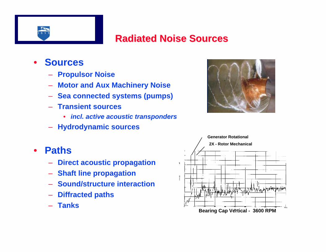
Radiated Noise Sources Radiated Noise Sources
• Sources– Propulsor Noise– Motor and Aux Machinery Noise – Sea connected systems (pumps)– Transient sources
• incl. active acoustic transponders– Hydrodynamic sources
• Paths– Direct acoustic propagation– Shaft line propagation– Sound/structure interaction– Diffracted paths– Tanks
Bearing Cap Vertical - 3600 RPM
Generator Rotational2X - Rotor Mechanical
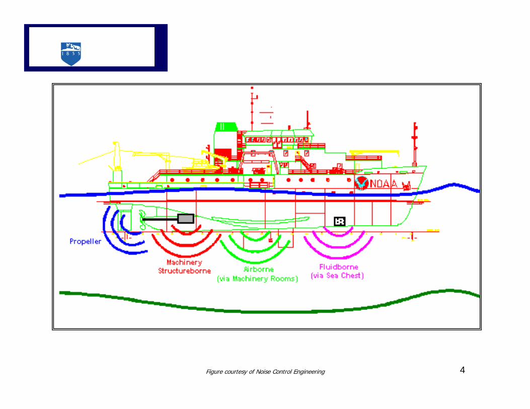
Figure courtesy of Noise Control Engineering 4
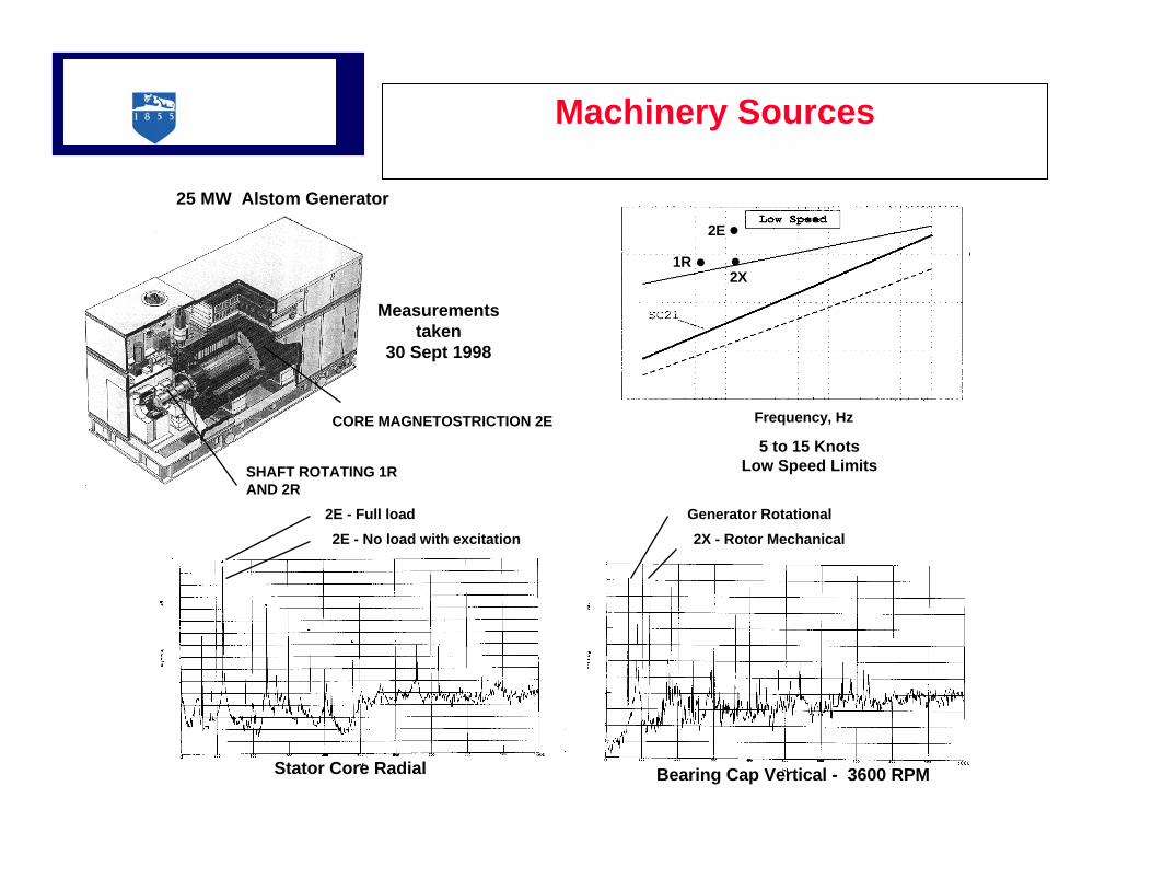
Machinery Sources
Stator Core Radial Bearing Cap Vertical - 3600 RPM
2E - Full load2E - No load with excitation
Generator Rotational2X - Rotor Mechanical
SHAFT ROTATING 1RAND 2R
CORE MAGNETOSTRICTION 2E
5 to 15 KnotsLow Speed Limits
Frequency, Hz
25 MW Alstom Generator
Measurementstaken
30 Sept 1998
2E
2X1R
6
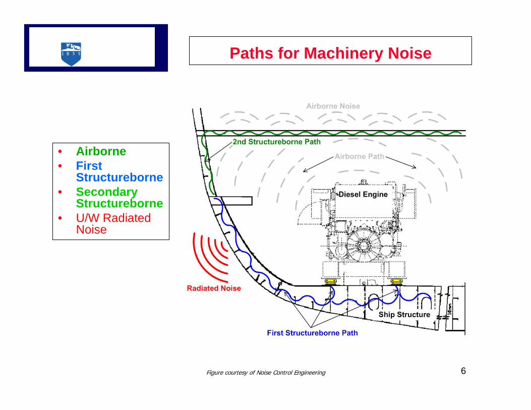
Paths for Machinery Noise
• Airborne• First
Structureborne• Secondary
Structureborne• U/W Radiated
Noise
Figure courtesy of Noise Control Engineering
7
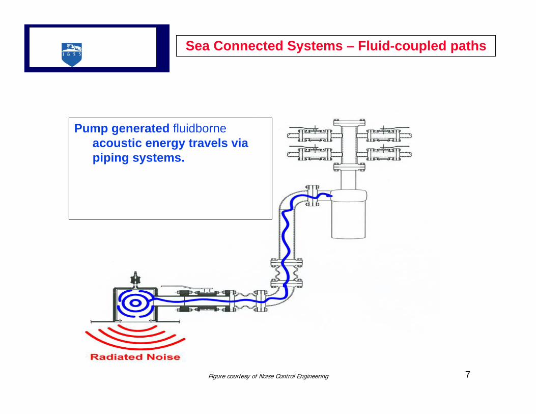
Sea Connected Systems – Fluid-coupled paths
Pump generated fluidborneacoustic energy travels via piping systems.
Figure courtesy of Noise Control Engineering
Frequency (Hz)
SP
L
101 102 103 104110
115
120
125
130
135
140p
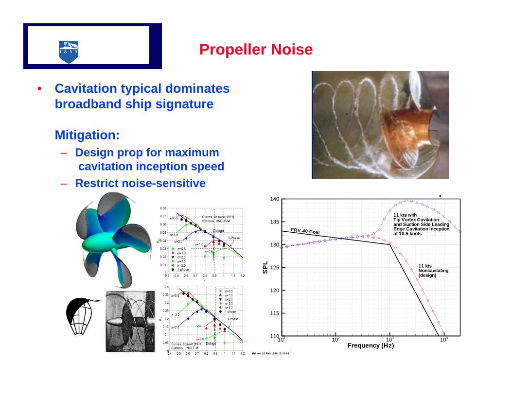
11 kts withTip Vortex Cavitationand Suction Side LeadingEdge Cavitation Inceptionat 10.5 knots
11 ktsNoncavitating(design)
FRV-40 Goal
Printed 10 Feb 1999 13:14:03
Propeller Noise
• Cavitation typical dominates broadband ship signature
Mitigation:– Design prop for maximum
cavitation inception speed– Restrict noise-sensitive
operations to speeds less than cavitation inception
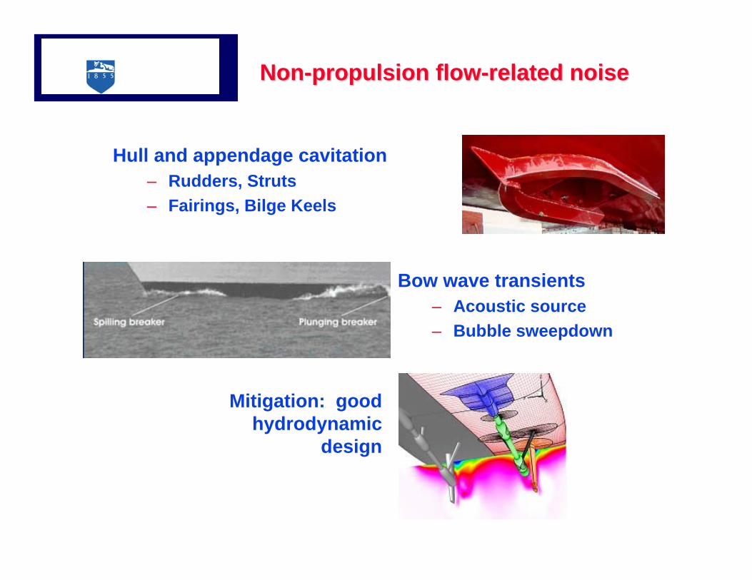
NonNon--propulsion flowpropulsion flow--related noiserelated noise
Bow wave transients– Acoustic source– Bubble sweepdown
Hull and appendage cavitation– Rudders, Struts– Fairings, Bilge Keels
Mitigation: good hydrodynamic
design
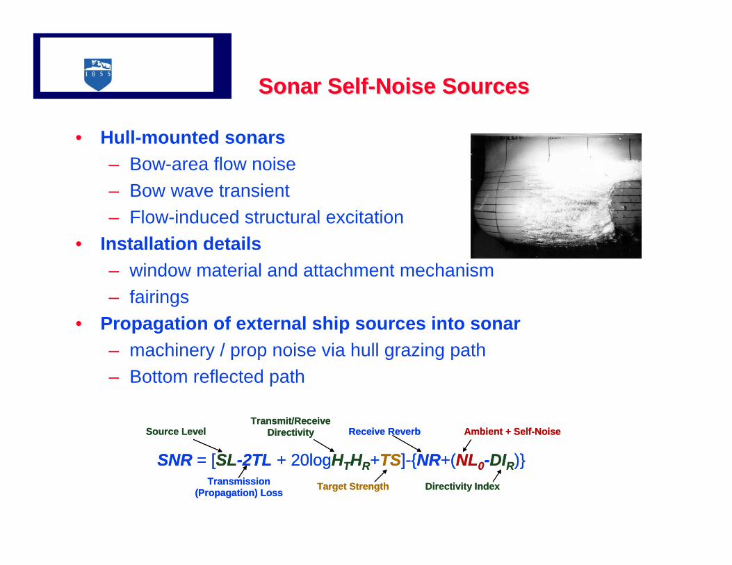
Sonar SelfSonar Self--Noise Sources Noise Sources
• Hull-mounted sonars– Bow-area flow noise– Bow wave transient– Flow-induced structural excitation
• Installation details – window material and attachment mechanism– fairings
• Propagation of external ship sources into sonar– machinery / prop noise via hull grazing path– Bottom reflected path
SNR = [SL-2TL + 20logHTHR+TS]-{NR+(NL0-DIR)}
Source LevelTransmit/Receive
Directivity
Target StrengthTransmission (Propagation) Loss
Receive Reverb Ambient + Self-Noise
Directivity Index
SNR = [SL-2TL + 20logHTHR+TS]-{NR+(NL0-DIR)}
Source LevelTransmit/Receive
Directivity
Target StrengthTransmission (Propagation) Loss
Receive Reverb Ambient + Self-Noise
Directivity Index
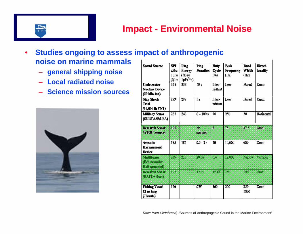
Impact Impact -- Environmental NoiseEnvironmental Noise
• Studies ongoing to assess impact of anthropogenic noise on marine mammals – general shipping noise– Local radiated noise – Science mission sources
Table from Hildebrand, “Sources of Anthropogenic Sound in the Marine Environment”
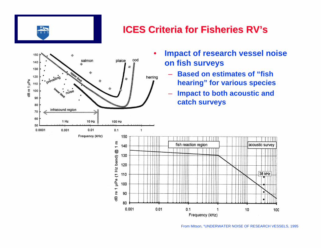
ICES Criteria for Fisheries RVICES Criteria for Fisheries RV’’ss
From Mitson, “UNDERWATER NOISE OF RESEARCH VESSELS, 1995
• Impact of research vessel noise on fish surveys– Based on estimates of “fish
hearing” for various species – Impact to both acoustic and
catch surveys
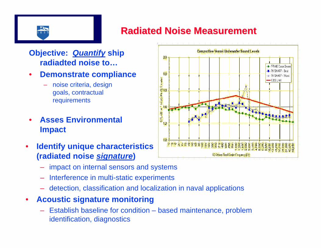
Radiated Noise MeasurementRadiated Noise Measurement
Objective: Quantify ship radiadted noise to…
• Demonstrate compliance– noise criteria, design
goals, contractual requirements
• Asses Environmental Impact
• Identify unique characteristics (radiated noise signature)– impact on internal sensors and systems– Interference in multi-static experiments– detection, classification and localization in naval applications
• Acoustic signature monitoring– Establish baseline for condition – based maintenance, problem
identification, diagnostics
DefinitionsDefinitions
• Radiated Noise– vessel noise that is transmitted into the water and can be detected
by off-board receivers• Typically reported as One Third octave (OTO) Band • Narrowband (1 HZ) data used to characterize machinery tonals
• Radiated Noise Source Level – Equivalent simple source (omnidirectional monopole) level
SL dB re 1 µPa @ 1m• Back-propagated to 1m assuming spherical spreading from a far field,
free-field measurement
• Platform Noise– Ship noise that can be detected by acoustic or vibration sensors
• Not necessarily detectable as radiated noise
• Sonar Self-Noise– Received acoustic levels in the output of onboard system
receiving band(s) due to self-generated platform noise sources
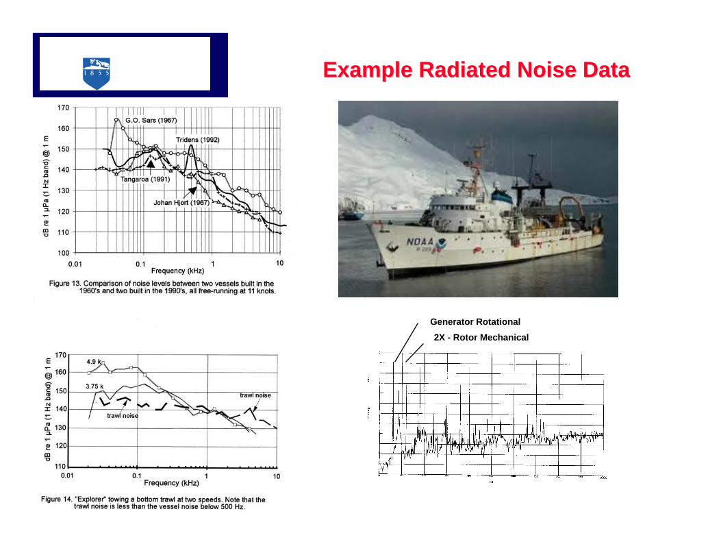
Example Radiated Noise DataExample Radiated Noise Data
Generator Rotational2X - Rotor Mechanical
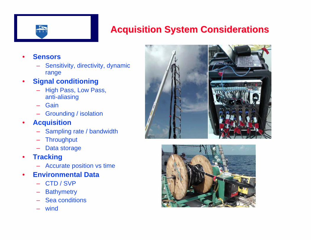
Acquisition System ConsiderationsAcquisition System Considerations
• Sensors– Sensitivity, directivity, dynamic
range• Signal conditioning
– High Pass, Low Pass, anti-aliasing
– Gain– Grounding / isolation
• Acquisition– Sampling rate / bandwidth– Throughput– Data storage
• Tracking– Accurate position vs time
• Environmental Data– CTD / SVP– Bathymetry– Sea conditions– wind
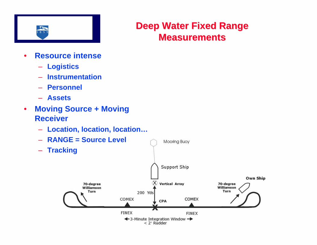
Deep Water Fixed Range Deep Water Fixed Range MeasurementsMeasurements
• Resource intense – Logistics– Instrumentation– Personnel– Assets
• Moving Source + Moving Receiver– Location, location, location…– RANGE = Source Level– Tracking
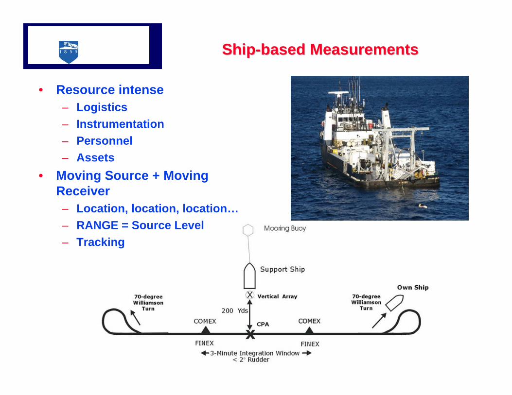
ShipShip--based Measurementsbased Measurements
• Resource intense – Logistics– Instrumentation– Personnel– Assets
• Moving Source + Moving Receiver– Location, location, location…– RANGE = Source Level– Tracking
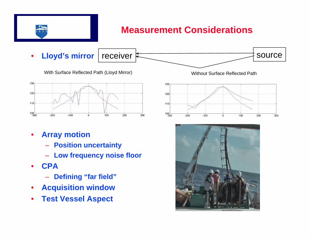
Measurement Considerations
• Lloyd’s mirror
• Array motion– Position uncertainty– Low frequency noise floor
• CPA– Defining “far field”
• Acquisition window • Test Vessel Aspect
receiver source
With Surface Reflected Path (Lloyd Mirror) Without Surface Reflected Path
16 / 20
Range (m) Range (m)
Leve
l (dB
) –5
dB In
crem
ents
Leve
l (dB
) –5
dB In
crem
ents
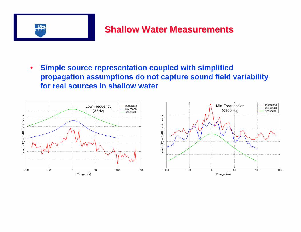
Low Frequency (32Hz)
Mid-Frequencies (6300 Hz)
Shallow Water MeasurementsShallow Water Measurements
• Simple source representation coupled with simplified propagation assumptions do not capture sound field variability for real sources in shallow water