Embed Size (px)
Citation preview

Technical Note
Radiating Cable (RCL/RCH)
Performance Test & Design Guidlines Document Code: TN02-RadiatingCable-14 Date: March 6, 2014

Technical Note TN02-RadiatingCable-14
ProSoft Technology, Inc. March 6, 2014 Page 2 of 15
Document Information Author Stuart Siegel
Description Performance Test & Design Guidelines
Date March 6, 2014
Product Name Radiating Cable RCL/RCH
Document Code TN02-RadiatingCable-14
ProSoft Technology
5201 Truxtun Ave., 3rd Floor Bakersfield, CA 93309 +1 (661) 716-5100 +1 (661) 716-5101 (Fax) www.prosoft-technology.com
Copyright © ProSoft Technology, Inc. 2014. All Rights Reserved.
ProSoft Technology ® ProLinx ®, inRAx ®, ProTalk®, and RadioLinx ® are Registered Trademarks of ProSoft Technology, Inc. All other brand or product names are or may be trademarks of, and are used to identify products and services of, their respective owners.
How to contact us: Sales & Support All ProSoft Technology® products are backed with unlimited technical support. Contact our worldwide Technical Support team directly by phone or email:
Asia Pacific
+603.7724.2080, [email protected] Languages spoken include: Chinese, Japanese, English
Europe – Middle East – Africa
+33 (0) 5.34.36.87.20, [email protected] Languages spoken include: French, English [email protected], fax to +33 (0) 5.61.78.40.52
North America
+1.661.716.5100, [email protected] Languages spoken include: English, Spanish [email protected], fax to +1 661.716.5101
Latin America (Sales only)
+1.281.298.9109, [email protected] Languages spoken include: Spanish, English
Brasil
+55-11.5084.5178, [email protected] Languages spoken include: Portuguese, English

Technical Note TN02-RadiatingCable-14
ProSoft Technology, Inc. March 6, 2014 Page 3 of 15
Contents
Document Information ............................................................................................................... 2
1 INTRODUCTION ....................................................................................................................... 5
Basics…. .................................................................................................................................... 5 Cable……. ................................................................................................................................. 7 Cable Installation Guidelines ..................................................................................................... 7
2 TEST CASES ............................................................................................................................ 9
Test Case 1 - 802.11n Fast Industrial Hotspot (RLX2-IHNF) on Single RC Segment ............ 10 Test Case 2 - 802.11n Fast Industrial Hotspot (RLX2-IHNF) on 2 RC Segments .................. 11 Test Case 3 - Two (2) 802.11n Fast Industrial Hotspot (RLX2-IHNF) using Fast Roam ........ 12 Test Case 4 - 802.11g High Power Industrial Hotspot (RLX2-IHG) ........................................ 13 Test Case 5 - 802.11a High Power Industrial Hotspot (RLX2-IHA) ........................................ 14
3 TEST CONCLUSIONS & BEST PRACTICES ........................................................................ 15

Technical Note TN02-RadiatingCable-14
ProSoft Technology, Inc. March 6, 2014 Page 4 of 15
Technical Note TN02-RadiatingCable-14
ProSoft Technology, Inc. March 6, 2014 Page 5 of 15
1 Introduction
Radiating Cable (RC) is used for industrial wireless communications in situations where standard discrete antennas cannot be used effectively. Radiating cable may be used in wireless applications where antennas cannot reach due do obstructions such as tunnels or monorails. This document refers to applications and test results using ProSoft Technology Industrial Hotspots with Eupen-manufactured radiating cables.
Radiating cable (also known as "leaky feeder") has been applied for decades in low frequency radio applications. Highway and railway tunnels commonly use radiating cable for emergency radio communication and more recently, cellular phone connectivity. Radiating cable has also been installed in mines for voice radio communications.
The focus of this guide is applying 802.11 wireless technology over radiating cable for industrial control networking. ProSoft Technology specializes in wireless solutions for factory automation applications. These critical systems are complex to engineer. Partnering with a technology company with industrial networking knowledge and field application is crucial for success. While this guide contains valuable general information and suggested architectures, it is recommended to consult with our Wireless Support Engineers to ensure a successful project.
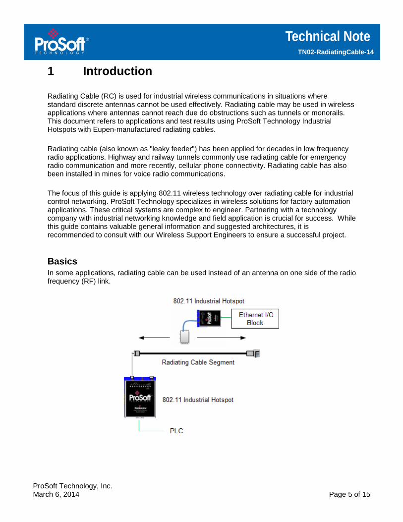
Basics In some applications, radiating cable can be used instead of an antenna on one side of the radio frequency (RF) link.

Technical Note TN02-RadiatingCable-14
ProSoft Technology, Inc. March 6, 2014 Page 6 of 15
Unlike antennas, radiating cable does not amplify the signal with gain. The RF energy is attenuated as it travels through the cable. This attenuation is called longitudinal loss and increases with the distance the signal travels through the cable. There is also loss based on the air gap between the radiating cable and the antenna for the other radio in the link. This attenuation is called coupling loss and it increases with the gap. By using proper lengths of the cable and maintaining a consistent, short gap between the antenna and cable, a strong radio link can be maintained as the antenna travels along the cable. Slots are cut in the shield part of the coax (underneath the insulation) to permit RF energy to propagate out of and be received into the cable. Sizing and spacing of these slots are based on the frequency of the radio signal.
Radiating Cable Construction (cutaway view)
The slots are arranged along one side of the cable and should face the antenna on the other side of the RF link, so cable orientation is critical for proper performance. To help installation, these slots are opposite to the ridge built into the outer jacket that runs the length of the cable.
Traditional discrete antennas are recommended over RC for most applications unless they are not capable of supporting reliable radio links due to confined spaces or line-of-sight challenges. The benefit of using RC lies in applications with moving equipment and machines that require a high quality RF connection as it travels along a track or through a tunnel.
Since RF radiates over several meters from RC cable, it is best practice to ensure no other Wi-Fi system uses the same or overlapping channels.
Proper mounting of RC is important to the success of a system. Please follow installation guidelines. Improperly mounting the cable will result in unwanted losses and poor performance. A terminator is required at the end of the cable to prevent RF reflection in the cable.

Technical Note TN02-RadiatingCable-14
ProSoft Technology, Inc. March 6, 2014 Page 7 of 15
Cable
Radiating cable is 1/2" coaxial style cable. There are two basic types of Radiating Cable:
• RCL - Low Frequency (including 2.4 GHz band)
• RCH - High Frequency (5 GHz band)
The cable is available pre-terminated (N female connectors installed) or in bulk spools. Bulk cable must be properly terminated during installation. Typical Cable Losses
RCH (5200GHz) = 19.1db/100m, 5.8db/100’ RCH (5800GHz) = 21.5db/100m, 6.5db/100’
RCL (2.4GHz) = 14.4db/100m, 4.47db/100’
Cable Installation Guidelines
The RF radiating characteristics of RC are such that proper installation is crucial to achieve expected wireless performance. This includes ensuring that the cable is installed far enough away from metal and concrete structures that may affect its RF characteristics. Plastic spacers with cable hangers (clamps) provide a practical way to install the RC. Because cable sags are undesirable, it is recommended to install hangers/clamps every meter. Plastic clamps can be used every meter. It is recommended that fire resistant clamps such as stainless steel be installed every 10th meter to better secure the cable (i.e. if there is a fire, the stainless steel clamps will ensure that the cable does not fall in a dangerous way).
Once the hangers are installed, the terminated cable is then attached to the hanger clamps. The RC cable is clearly marked with a ridge indicating the opposite side of the RF propagation. The cable needs to be placed such that its RF signal is in the direction of the device/machine antenna.

Technical Note TN02-RadiatingCable-14
ProSoft Technology, Inc. March 6, 2014 Page 8 of 15

Technical Note TN02-RadiatingCable-14
ProSoft Technology, Inc. March 6, 2014 Page 9 of 15
2 Test Cases
ProSoft Technology has performed extensive RC range and data rate performance testing using 802.11a, 802.11g and 802.11n wireless technologies. The tests were performed to gauge actual field performance, however installation environment and conditions can impact specific performance. Please consult with our Wireless Support Engineers for project assistance. Test Conditions:
• ProSoft Technology Industrial Hotspots used for all tests.
• 802.11 clear channel (no other RF system in the same frequency range).
• 4dBi omni-directional antenna on the mobile device.
• The omni antenna was 10 cm (4") away from the RC segment (note that performance will decrease the further the antenna is away from the RC).
• EtherNet/IP controllers and I/O blocks used to generate high data rate. • The test results are given for the connection requirements to maintain the fastest
communication data rates for each tested Industrial Hotspot.

Technical Note TN02-RadiatingCable-14
ProSoft Technology, Inc. March 6, 2014 Page 10 of 15
Test Case 1 - 802.11n Fast Industrial Hotspot (RLX2-IHNF) on Single RC Segment
802.11n Test Case 1 System Architecture
Radiating Cable 802.11n Test Case 1 Results
Cable Type
Frequency Band
Channel Width
RC Segment Distance Limit
Lowest RSSI
Max Data
Rate Observed
Average EIP
Packets/Sec
RCL 2.4 GHz 20 MHz 150 meters -63 dB 65 Mbps 5,000
RCH 5 GHz 20 MHz 125 meters -63 dB 65 Mbps 5,000
RCH 5 GHz 40 MHz (2
channels) 125 Meters - 63 dB 150 Mbps 6,000
Test Notes:
• 802.11n rates up to MCS7 (single stream rates only) • Omni antenna at 10 cm (4") from RC Segment • Clear RF channel (no other RF systems present)

Technical Note TN02-RadiatingCable-14
ProSoft Technology, Inc. March 6, 2014 Page 11 of 15
Test Case 2 - 802.11n Fast Industrial Hotspot (RLX2-IHNF) on 2 RC Segments
802.11n Test Case 2 System Architecture
Radiating Cable 802.11n Test Case 2 Results
Cable Type
Frequency Band
Channel Width
Segment X
Segment Y
Total
Effective Distance
(X+Y-1m
overlap)
Lowest RSSI
Max Data Rate
Observed
Average
EIP
Packets/
Sec
RCL 2.4 GHz 20 MHz 150 m 150 m 299 m -63 dB 65 Mbps 5,000
RCH 5 GHz 20 MHz 125 m 125 m 249 m -63 dB 65 Mbps 5,000
RCH 5 GHz 40 MHz (2
channels) 125 M 125 M 249 m - 63 dB 150
Mbps 6,000
Test Notes:
• RLX2-IHNF antenna ports A and C used • 802.11n rates up to MCS7 (single stream rates only) • Omni antenna at 10 cm (4") from RC Segment • Segment X and Y overlap by 1 meter • Clear RF channel (no other RF systems present)

Technical Note TN02-RadiatingCable-14
ProSoft Technology, Inc. March 6, 2014 Page 12 of 15
Test Case 3 - Two (2) 802.11n Fast Industrial Hotspot (RLX2-IHNF) using Fast Roam
802.11n Test Case 3 System Architecture
Radiating Cable 802.11n Test Case 3 Results
Cable Type
Frequency Band
Channel Width
Total Effective Distance (X+Y-1m
overlap)
Roam Time
Lowest RSSI Max Data Rate
Observed
Average
EIP
Packets/
Sec
RCL 2.4 GHz 20 MHz 299 m < 40ms -63 dB 65 Mbps 5,000
RCH 5 GHz 20 MHz 249 m < 40ms -63 dB 65 Mbps 5,000
RCH 5 GHz 40 MHz (2
channels) 249 m < 40ms - 63 dB 150 Mbps 6,000
Test Notes:
• Roam times of less than 40ms maintained PLC I/O connections - no faults • 802.11n rates up to MCS7 (single stream rates only) • Omni antenna at 10 cm (4") from RC Segment • Segment X and Y overlap by 1 meter • Clear RF channel (no other RF systems present)
Technical Note TN02-RadiatingCable-14
ProSoft Technology, Inc. March 6, 2014 Page 13 of 15
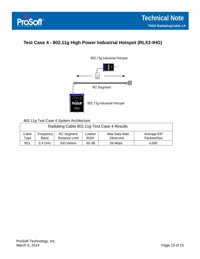
Test Case 4 - 802.11g High Power Industrial Hotspot (RLX2-IHG)
802.11g Test Case 4 System Architecture
Radiating Cable 802.11g Test Case 4 Results
Cable Type
Frequency Band
RC Segment Distance Limit
Lowest RSSI
Max Data Rate
Observed Average EIP
Packets/Sec
RCL 2.4 GHz 200 meters -65 dB 58 Mbps 4,000

Technical Note TN02-RadiatingCable-14
ProSoft Technology, Inc. March 6, 2014 Page 14 of 15
Test Case 5 - 802.11a High Power Industrial Hotspot (RLX2-IHA)
802.11a Test Case 5 System Architecture
Radiating Cable 802.11a Test Case 5 Results
Cable Type
Frequency Band
RC Segment Distance Limit
Lowest RSSI
Max Data Rate Observed
Average EIP
Packets/Sec
RCH 5 GHz 150 meters -65 dB 58 Mbps 4,000
Technical Note TN02-RadiatingCable-14
ProSoft Technology, Inc. March 6, 2014 Page 15 of 15
3 Test Conclusions & Best Practices
Radiating Cable (RC) is an effective way to support high speed automation systems using
802.11 wireless technologies. However, RC is much more complex and costly to install
compared to traditional discrete antennas. RC should be used in situations where discrete
antennas are not practical (confined spaces, large monorail systems and tunnels) where
establishing line-of-sight is difficult.
RF performance with RC is very good at short distance from antenna to RC. However, the 802.11n speeds were slower compared to using MIMO (multiple-input and multiple-output), as dual streams is improbable with RC. If MIMOs can be used, it is preferable to RC.
Omni directional antennas showed the best performance for communicating to the RC segment. Directional (higher gain) antennas did not perform as well.
Radiating Cable is a good option for those applications where traditional antennas are not feasible. The wireless technology selection, cable design, and installation must be done precisely to assure good performance.