Embed Size (px)
Citation preview
Radiation Tolerance of Nanostructured Ceramic/Metal Composites
Michael NastasiDirector, Nebraska Center for Energy Sciences Research
Elmer Koch Professor, Mechanical and Materials EngineeringUniversity of Nebraska-Lincoln
Work supported by DoE Office of Nuclear Energy, Nuclear Energy Enabling Technologies, award DE-NE0000533
DOE-NE Materials Crosscut Coordination Meeting
September 16th, 2015
Co-Investigators: Lin Shao, TAMU and Michael Demkowicz, MIT
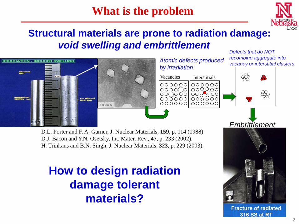
Vacancies Interstitials
Atomic defects produced by irradiation
Embrittlement
Defects that do NOT recombine aggregate into vacancy or interstitial clusters
D.L. Porter and F. A. Garner, J. Nuclear Materials, 159, p. 114 (1988)D.J. Bacon and Y.N. Osetsky, Int. Mater. Rev., 47, p. 233 (2002).H. Trinkaus and B.N. Singh, J. Nuclear Materials, 323, p. 229 (2003).
Structural materials are prone to radiation damage: void swelling and embrittlement
What is the problem
How to design radiation damage tolerant
materials?2
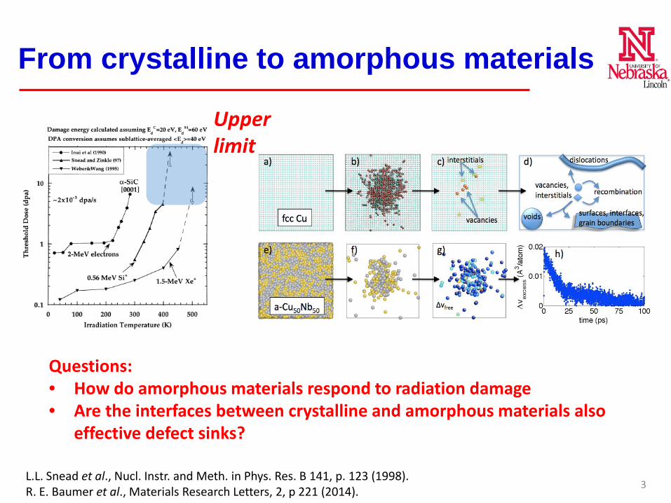
Upper limit
L.L. Snead et al., Nucl. Instr. and Meth. in Phys. Res. B 141, p. 123 (1998).R. E. Baumer et al., Materials Research Letters, 2, p 221 (2014).
From crystalline to amorphous materials
3
Questions: • How do amorphous materials respond to radiation damage• Are the interfaces between crystalline and amorphous materials also
effective defect sinks?
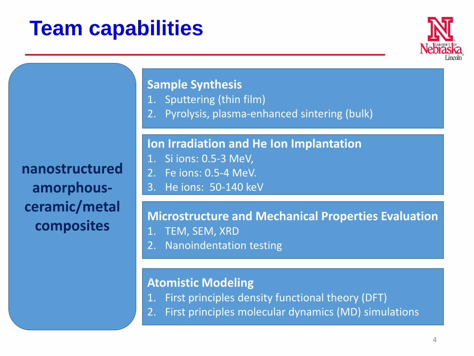
Team capabilities
4
nanostructured amorphous-
ceramic/metal composites
Sample Synthesis1. Sputtering (thin film)2. Pyrolysis, plasma-enhanced sintering (bulk)
Ion Irradiation and He Ion Implantation1. Si ions: 0.5-3 MeV, 2. Fe ions: 0.5-4 MeV. 3. He ions: 50-140 keV
Microstructure and Mechanical Properties Evaluation1. TEM, SEM, XRD2. Nanoindentation testing
Atomistic Modeling 1. First principles density functional theory (DFT)2. First principles molecular dynamics (MD) simulations
Outline
• Radiation tolerance of amorphous SiOC
• Radiation tolerance of Fe/SiOC nanocomposites
• Modelling
• Summary
5
6
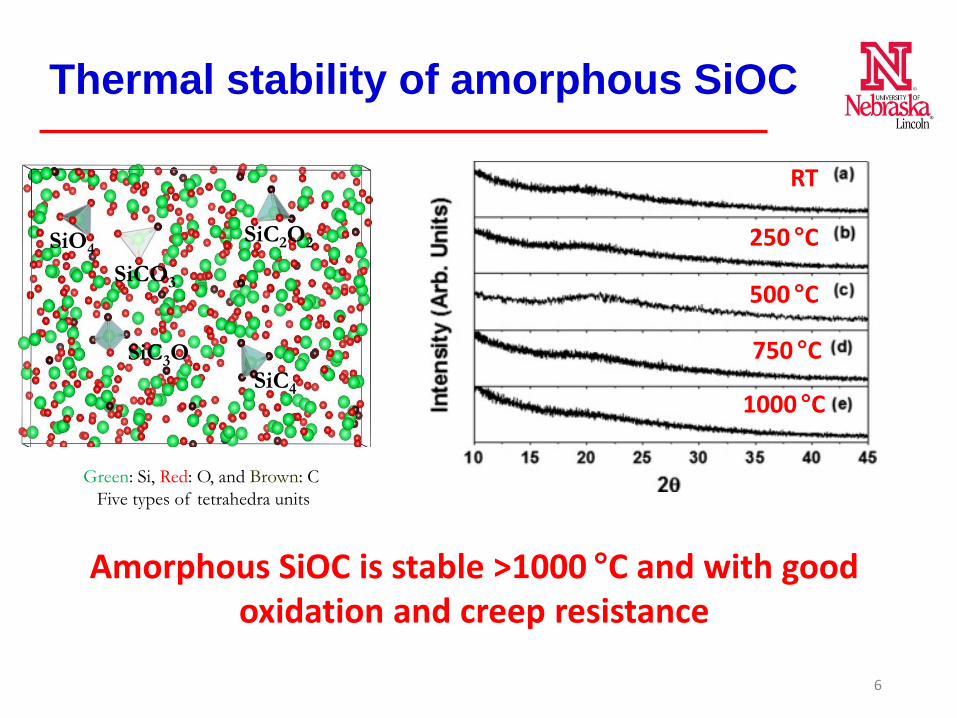
Green: Si, Red: O, and Brown: CFive types of tetrahedra units
SiO4
SiCO3
SiC2O2
SiC3OSiC4
Amorphous SiOC is stable >1000 °C and with good oxidation and creep resistance
Thermal stability of amorphous SiOC
1000 °C
RT
750 °C
500 °C
250 °C
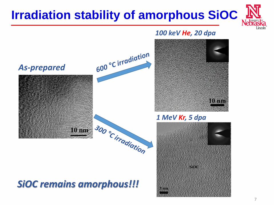
Irradiation stability of amorphous SiOC
7
SiOC remains amorphous!!!
10 nm
As-prepared
100 keV He, 20 dpa
1 MeV Kr, 5 dpa
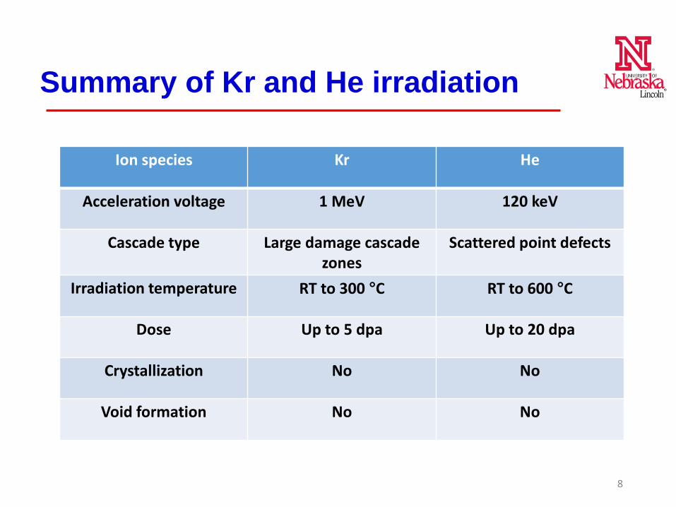
Summary of Kr and He irradiation
Ion species Kr He
Acceleration voltage 1 MeV 120 keV
Cascade type Large damage cascade zones
Scattered point defects
Irradiation temperature RT to 300 °C RT to 600 °C
Dose Up to 5 dpa Up to 20 dpa
Crystallization No No
Void formation No No
8
Outline
• Radiation tolerance of amorphous SiOC
• Radiation tolerance of Fe/SiOC nanocomposites
• Modelling
• Summary
9
10
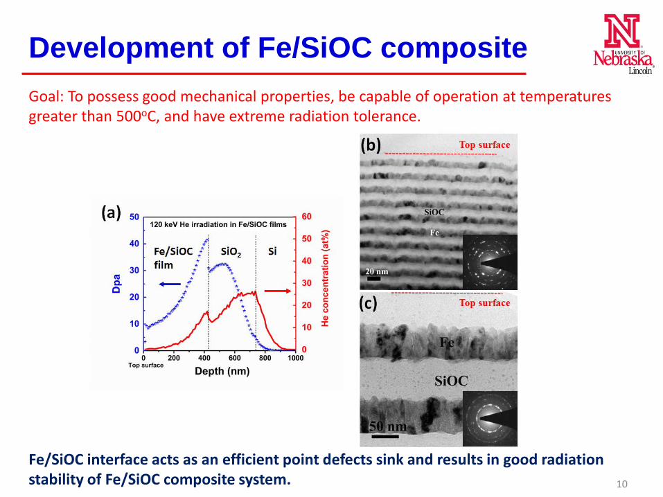
Development of Fe/SiOC compositeGoal: To possess good mechanical properties, be capable of operation at temperatures greater than 500oC, and have extreme radiation tolerance.
Fe/SiOC interface acts as an efficient point defects sink and results in good radiation stability of Fe/SiOC composite system.
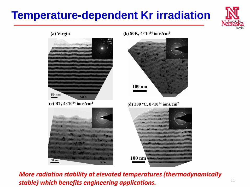
Temperature-dependent Kr irradiation(b) 50K, 4×10¹⁴ ions/cm2
(c) RT, 4×10¹⁴ ions/cm2 (d) 300 oC, 8×10¹⁴ ions/cm2
(a) Virgin
{110}{200}{211}
More radiation stability at elevated temperatures (thermodynamically stable) which benefits engineering applications. 11
Outline
• Radiation tolerance of amorphous SiOC
• Radiation tolerance of Fe/SiOC nanocomposites
• Modelling
• Summary
12
SiO4
SiCO3
SiC3O
SiC2O2
SiC4
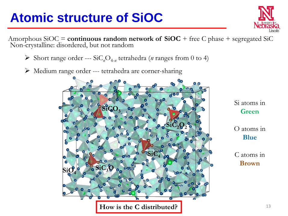
Non-crystalline: disordered, but not random
Short range order --- SiCnO4-n tetrahedra (n ranges from 0 to 4)
Medium range order --- tetrahedra are corner-sharing
Si atoms in Green
O atoms in Blue
C atoms in Brown
Amorphous SiOC = continuous random network of SiOC + free C phase + segregated SiC
Atomic structure of SiOC
How is the C distributed? 13
(a) (b)
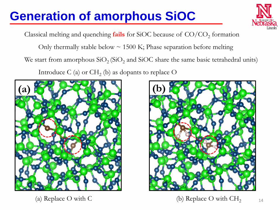
(a) Replace O with C (b) Replace O with CH2
Generation of amorphous SiOCClassical melting and quenching fails for SiOC because of CO/CO2 formation
Only thermally stable below ~ 1500 K; Phase separation before melting
We start from amorphous SiO2 (SiO2 and SiOC share the same basic tetrahedral units)
Introduce C (a) or CH2 (b) as dopants to replace O
14
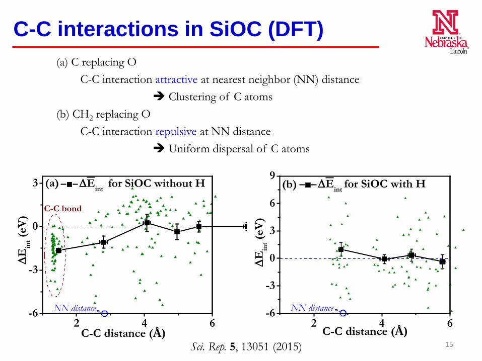
C-C interactions in SiOC (DFT)
2 4 6-6
-3
0
3
6
9
NN distance
∆E
int (e
V)
C-C distance (Å)
∆Eint for SiOC with H(b)
2 4 6-6
-3
0
3
C-C bond
NN distance
(a)
∆E
int (e
V)
C-C distance (Å)
∆Eint for SiOC without H
(a) C replacing OC-C interaction attractive at nearest neighbor (NN) distance
Clustering of C atoms(b) CH2 replacing O
C-C interaction repulsive at NN distance Uniform dispersal of C atoms
Sci. Rep. 5, 13051 (2015) 15
(a)
(b)
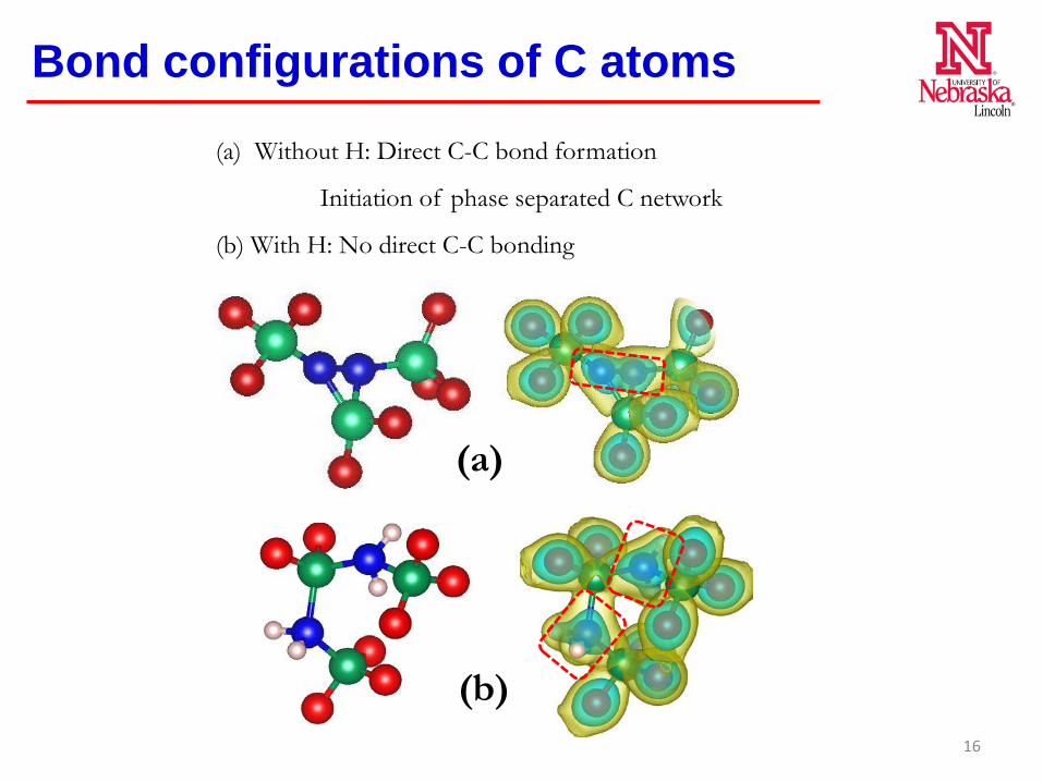
Bond configurations of C atoms
(a) Without H: Direct C-C bond formation
Initiation of phase separated C network
(b) With H: No direct C-C bonding
16
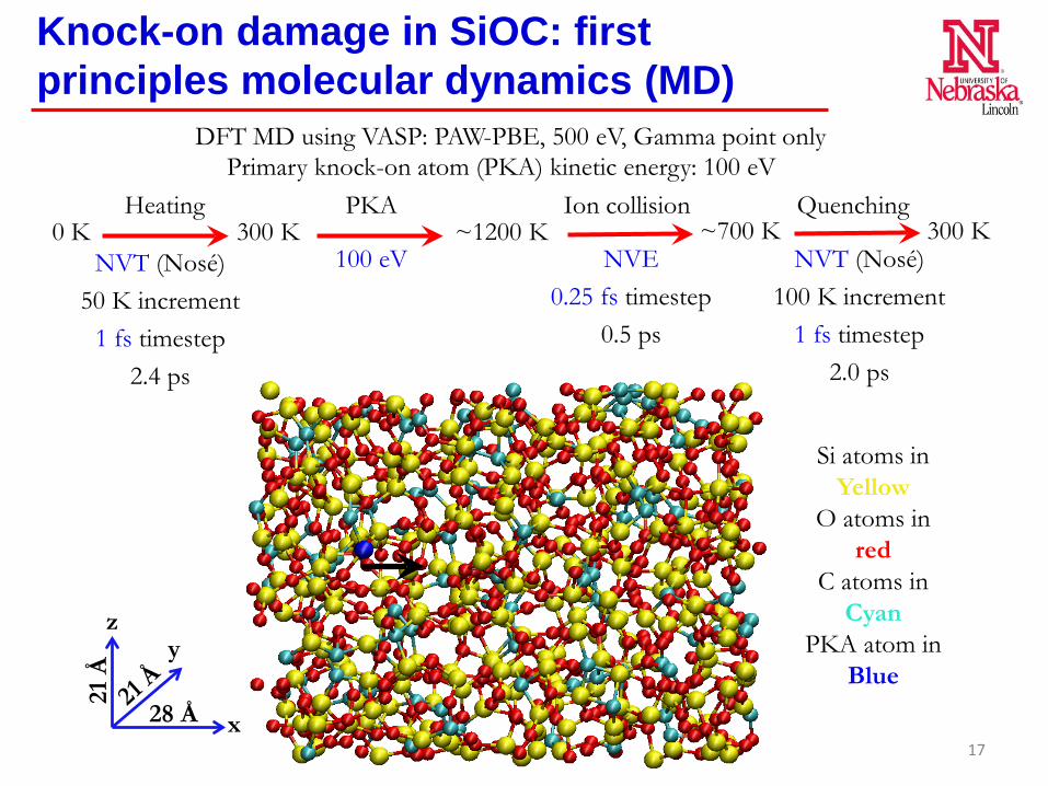
Knock-on damage in SiOC: first principles molecular dynamics (MD)
DFT MD using VASP: PAW-PBE, 500 eV, Gamma point onlyPrimary knock-on atom (PKA) kinetic energy: 100 eV
Heating PKA0 K 300 K ~1200 K ~700 K 300 K
Ion collision Quenching
NVT (Nosé)50 K increment
1 fs timestep2.4 ps
NVT (Nosé)100 K increment
1 fs timestep2.0 ps
NVE0.25 fs timestep
0.5 ps
100 eV
x
zy
21 Å
28 Å
Si atoms in Yellow
O atoms in red
C atoms in Cyan
PKA atom in Blue
17
0 400 800 1200
-6440
-6420
-6400
-6380
-6360SiOC Before
PKA After
Inte
rnal
ene
rgy
(eV
)
Time (fs)
0 400 800 1200
-6500
-6480
-6460
-6440
-6420 Before PKA After
Inte
rnal
ene
rgy
(eV
)
Time (fs)
SiO2
0 400 800
-7220
-7200
-7180
-7160
-7140
-7120SiOC with H Before
PKA After
Inte
rnal
ene
rgy
(eV
)
Time (fs)
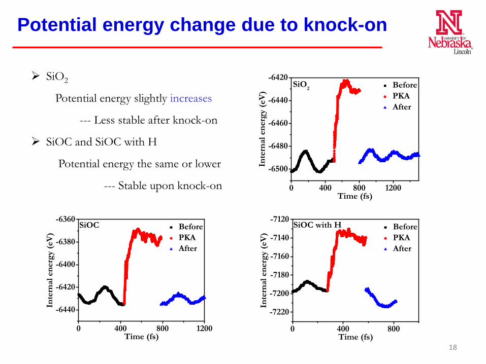
SiO2
Potential energy slightly increases
--- Less stable after knock-on
SiOC and SiOC with H
Potential energy the same or lower
--- Stable upon knock-on
Potential energy change due to knock-on
18
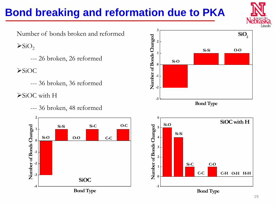
Bond breaking and reformation due to PKA
Number of bonds broken and reformed
SiO2
--- 26 broken, 26 reformed
SiOC
--- 36 broken, 36 reformed
SiOC with H
--- 36 broken, 48 reformed-3
-2
-1
0
1
2
3SiO2
O-OSi-Si
Num
ber o
f Bon
ds C
hang
ed
Si-O
Bond Type
-4
-3
-2
-1
0
1
2
SiOC
O-C
C-C
Si-C
O-O
Si-Si
Num
ber o
f Bon
ds C
hang
ed
Si-O
Bond Type-1
0
1
2
3
4
5
6SiOC with H
H-HO-HC-H
C-O
C-C
Si-C
Si-Si
Si-O
Num
ber o
f Bon
ds C
hang
ed
Bond Type19
Summary: Experimental
Amorphous SiOC is radiation stable (He and Kr)I. 20 dpa at 600 oC (He)II. 5 dpa at 300 oC (Kr)
Irradiation stability of Fe/SiOC nanocompositeI. Room temperature stability up to ~40 dpa. II. Amorphous SiOC/crystalline Fe interface is demonstrated as
defect sinks.III. Enhanced stability at elevated temperature.
20
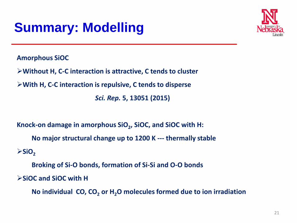
Amorphous SiOC
Without H, C-C interaction is attractive, C tends to cluster
With H, C-C interaction is repulsive, C tends to disperse
Sci. Rep. 5, 13051 (2015)
Knock-on damage in amorphous SiO2, SiOC, and SiOC with H:
No major structural change up to 1200 K --- thermally stable
SiO2
Broking of Si-O bonds, formation of Si-Si and O-O bonds
SiOC and SiOC with H
No individual CO, CO2 or H2O molecules formed due to ion irradiation
Summary: Modelling
21
Going Forward
• Year 1: Evaluation of the role of Fe/SiOC interfaces on defect mitigation out to harsher environments with >300 dpa and >500 oC. Evaluate the role of SiOC and Fe/SiOC interfaces on He incorporation. Determine mechanical properties (hardness, elastic modulus, fracture toughness and creep resistance) of SiOC and SiOC/Fe composites of various compositions, layer thicknesses, and volume fractions as a function of irradiation damage levels and irradiation temperatures. Continued development of empirical potentials and atomic structure descriptions for the amorphous alloys.
• Year 2: Further optimize compositions of SiOC ceramics and layered structures of Fe/SiOC to achieve the maximum radiation tolerance, and determine the roles of Fe and SiOC volume fractions on overall radiation tolerance, swelling resistance, and He solubility. Continue mechanical property evaluations. Multiscale modeling through integration of first principles calculations and molecular dynamics simulations to shed light onto the interactions of defects and gas atoms with interfaces.
• Year 3: Detailed experimental studies of irradiated composites using Fe(Cr) accompanied by modeling of cascade damage, defect behavior, swelling behavior, and diffusion. Mechanical property evaluations. Integration of modeling and experiments to shed light onto fundamentals and identify governing factors, which determine the maximum radiation tolerance of the composite materials.
22