Embed Size (px)
Citation preview

RADIO a TELEVISION DATA for
RADIOTRICIANS* & TELETRICIANS*
(*Registered U.S. Patent Office)
Prepared as a Service
Especially for Members of the
NATIONAL RADIO INSTITUTE ALUMNI ASSOCIATION
Washington 9, D. C.
Compiled by John H. Battison,
Director of Education, National Radio Institute
Reprinted from
TECHNICIAN and TELE-TECH
Copyrighted 1954 (all rights reserved) by
CALDWELL-CLEMENTS, INC.
480 Lexington Ave.
New York 17, N.Y.
•

Serviceman's Analysis of Simplified Outline of the NTSC Standards for
BY IRVING SHULMAN
• Servicemen may recall the excite-ment generated in 1951, when the FCC announced that it had approved a set of "spinning wheel" standards for commercial color - television transmissions. Controversial interest died when the Government issued an order that all color-television manufacturing be stopped, in order to conserve vital materials and man-power needed for defense. The color-television transmission
standards approved at that time were for a field sequential system, which was non-compatible with existing monochrome (black and white) transmissions. This meant that color telecasts could not be re-ceived on the millions of mono-chrome receivers already in use. To receive color transmissions in mono-chrome, the vertical and horizontal deflection circuits of the black-and-white receiver would have had to be altered; other circuit changes would have been necessary as well. There were various objections to
the field sequential system from an engineering viewpoint. Let us brief-ly review the field sequential sys-tem. A little history of this sort will enable us to better understand the system the FCC appi oved. Three fields were transmitted in
succession in the field sequential system: first red, then green and last blue. These fields represented the light falling on the camera tube from the color scene being tele-vised. Two sets of the above-men-tioned three fields were interlaced, producing a complete color picture or frame. Twenty-four frames were transmitted each second.
Defects of Old System
Now, the existing monochrome television channel has a bandwidth of 6 MC. In order to transmit three complete color pictures, with an amount of detail in each color equivalent to that present in the regular monochrome transmissions, much more than 6 MC is needed. Since only 6 MC was available, how-
Fig. 1—A) If no video information is being transmitted, the horizontal scanning lines may be represented as a series of pulses, equal in amplitude and separated from each other by 1/15,750 of a second. Only a few lines are shown. B) When video information is being transmitted, a cluster of video signals is associated with each scanning line. Note the empty spaces between clusters. Cl If color scanning lines were mixed with monochrome ones, the result could be pictorially indicated as shown above. D) Close-up view of monochrome and color scanning lines. El Enlarged view showing appearance of modulated scanning lines when color signals are inserted between the monochrome ones.
MONOCHROME SCANNING P1X CARRIER-1
I- L I I 1 ;, 3 3 1 i (A)
MONOCHROME P1X CARRIER1
(C) )
(E)
MONOCHROME P1X CARRIER
LAST -•-SCANNING
LINE
MONOCHROME COLOR WU> SCANNING
SCANNING rSUB-CARRIER LINES LINES I (3.503 MC)
1
(C)
CLUSTERS OF CLUSTERS OF CA.....0NOCHROME7<«—COLOR SIGNALS SIGNALS
IIIiI 1111,
!:: 11111
15,750 SEC+2
CLUSTERS OF MONOCHROME
SIGNALS
RELATIVELY EMPTY SPACES
1ST 2 ND 3RD SCANN NG SCANNING SCANNING
LINE LINE LINE
15,750 1 SEC
MONOCHROME SCANNING LINES
1 15,750 15,750 15,750 SEC SEC SEC
+2
COLOR SCANNING LINES
ever, the amount of detail contained in each color picture was reduced, in order to permit the color trans-missions to be squeezed into a 6 MC channel. As a result, picture detail was impaired. The low twenty-four frames per second rate introduced objectionable flicker, and color in-stability was noted in scenes where rapid motion was present. The radio and television industry's
NTSC (National Television Systems Committee) for the past two years has been developing and field testing a color television system. In July, 1953, this committee's proposal was submitted to the FCC for approval. When the FCC approved the NTSC color system, excitement was re-newed in the television industry. Public sale of color television re-ceivers was a fact in the early portion of 1954. Let us see what the NTSC has done to overcome the shortcomings of the field sequential system.
Definition and Compatibility
In the first place, the NTSC color system is a compatible one. A color broadcast can be received in mono-chrome, on a conventional black-and-white set. No alterations or circuit changes are needed. Secondly, NTSC color transmis-
sions will provide all the detail pres-ent in monochrome transmissions. The NTSC transmission is actually a high-definition monochrome pic-ture with color added; yet it needs only the 6 MC allocated for the reg-ular black-and-white television transmission. How was this miracle accomplished, when only a few years ago it was thought that 12 MC of bandwidth would be required for a color transmission of equivalent fidelity? We'll soon see. The engineers had a tough nut
to crack. These were the problems that confronted them: 1—The color system had to be compatible with monochrome TV. 2—It had to pro-vide pictures containing detail equivalent to that present in black-and-white TV. 3—The colors had to be convincing to the eye. 4—The system had to provide freedom from flicker, and color instability. 5—The
2
the New TV Color System Color Transmission That Have Been Approved by the FCC
color system had to stay within the existing 6 MC monochrome TV channel.
Investigations disclosed that the human eye had certain character-istics of which advantage could be taken: 1—In the case of large areas, the
eye has three-color vision. That is, any color scene can be reproduced by blending in the proper propor-tions of light from three "primary" colors, usually red, green and blue. 2—With respect to areas contain-
ing medium-sized detail, the eye needs only two-color vision. Blues become indistinguishable from greys or yellows of equal brightness in such cases. Browns tend to blend in with crimsons. Light from only two primary colors is needed in these instances to reproduce the color scene. 3—The eye is practically color-
blind when viewing small detail.
Adding Color
These findings, abetted by a great deal of experimentation, resulted in the conclusion that if a high-defini-tion monochrome signal were trans-mitted, only a relatively small amount of coloring information would have to be added to create an acceptable color picture. Tests showed that only 1.5 MC of band-width would be required to trans-mit the necessary color information. The process of superimposing a low-definition color picture on a high-definition black and white one, in-cidentally, is known as "mixed highs." Now, where can the additional 1.5
MC of radio-frequency spectrum needed to transmit the color infor-mation be obtained?
In seeking an answer to this ques-tion, engineers mulled over the fact that the normal monochrome sys-tem does not utilize the radio-fre-quency spectrum assigned to it effi-ciently. Many unused gaps exist in the range of frequencies covered by each channel. Researchers long ago pointed out
that for most scanned subjects, al-most all the signal energy present is concentrated at frequencies that are
whole multiples of the line-scanning frequency. About mid-way between these heavily-occupied areas are comparatively vacant ones. At odd multiples of half the line frequency, in other words, relatively unused stretches of spectrum are available (see Fig. 1A, B). Color information can be inserted into these gaps.
Band-Width Conservation
If the color carrier frequency is correctly chosen, the color signal sidebands (which contain the color information) will fall between the sidebands that contain the black and white information (see Fig. 1C, D, E). This process, which is known as band-sharing or frequency inter-leaving, was the one actually adopted by the NTSC.
In practice, it was discovered that mutual interference is present when band-sharing is practiced—that is, color signals interfere with the monochrome ones, and vice versa. The dot interference pattern created is, however, not objectionable at normal viewing distances (just as the presence of the scanning lines in a black and white picture is not annoying). The frequency chosen to represent
the color carrier is 3.57945 MC. It is referred to more conveniently as 3.58 MC. This frequency is an odd multiple of half the horizontal scan-
ning rate (15,750 x 455 = 3.58 MC, 2
app.). 3.58 MC is a video frequency; the corresponding radio frequency can be obtained by adding 3.58 MC to the black and white RF carrier. Band-sharing or frequency inter-
leaving does not make the color sub-carrier components completely in-visible in the black and white spec-trum, due to non-linearities that exist in the TV system, as well as insufficient persistencies of vision. These components are visible but not readily apparent at normal viewing distances, when 3.58 MC is used as the sub-carrier frequency. There are reasons why a lower fre-quency might be more desirable (to minimize cross-talk between color signals at the receiver, for instance); 3.58 MC was, however, determined by tests to be the best compromise frequency.
Band-Width Relationships
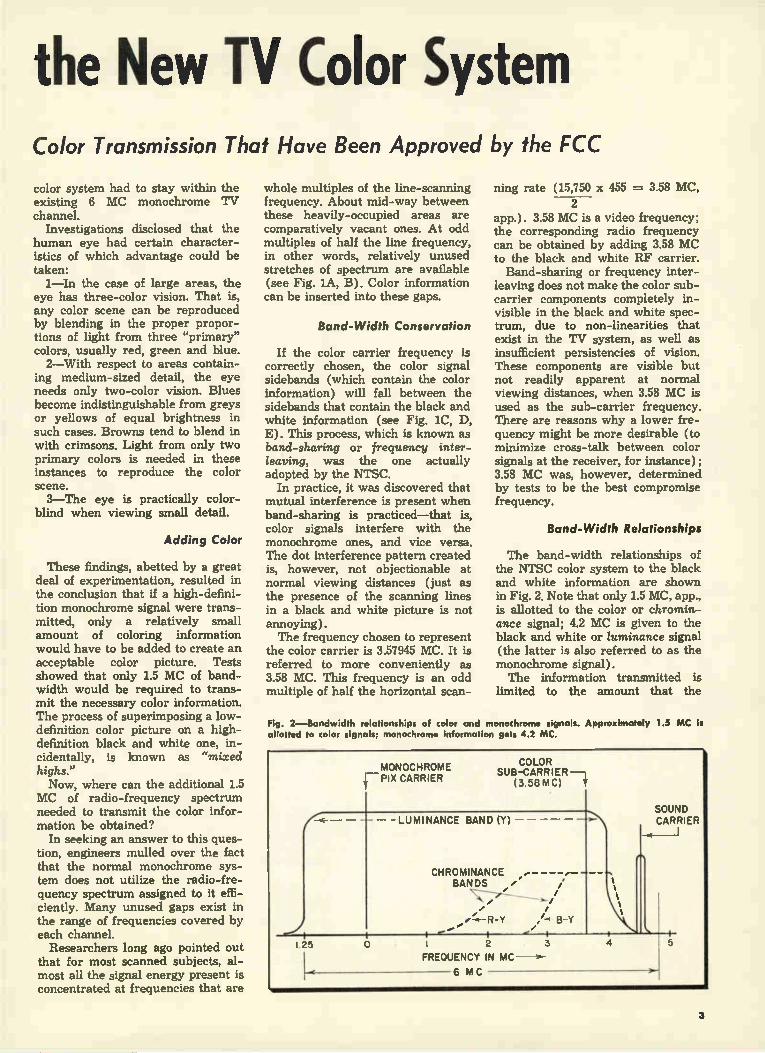
The band-width relationships of the NTSC color system to the black and white information are shown in Fig. 2. Note that only 1.5 MC, app., is allotted to the color or chromin-ance signal; 4.2 MC is given to the black and white or luminance signal (the latter is also referred to as the monochrome signal). The information transmitted is
limited to the amount that the
Fig. 2—Bandwidth relationships of color and monochrome signals. Approximately 1.5 MC is allotted to color signals; monochrome information gets 4.2 MC.
I 25
MONOCHROME F PIX CARRIER
COLOR SUB-CARRIER
(3.58 MC) t
— — — - LUMINANCE BAND (Y) — —
CHROMINANCE BANDS /
.... . -...... _...., . I i
0 I 2 3 FREQUENCY IN WIC —*-
6 MC
/
B-Y
SOUND CARRIER
4 5
3

human eye can readily perceive. The eye distinguishes between three separate, distinct visual sensations; 1—Brightness (relative intensity of light, or luminance). 2—Hue (the color or colors present—red, green and/or blue). 3—Saturation (purity of color present. A very deep red would represent a high degree of saturation. White would be equiva-lent to zero saturation.) The eye is sensitive to changes in brightness, but relatively insensitive to changes in hue.
Blue Band-Width
Coming back to Fig. 2, note the relatively small area allotted to the blue (B-Y) signal. The allotment is small because the eye is relatively insensitive to blue. High-frequency blues (fine detail) can't be detected as blues by the eye—only low-fre-quency blues (representing large areas) up to about 600 KC are re-cognized as blue by the eye. Double sidebands are allotted to
the blue signal—each blue frequen-cy is, so to speak, transmitted in duplicate. The red (R-Y) signal, on the other hand, is sent out with
one sideband and a vestige of an-other one (vestigial sideband trans-mission). Suitable response curves in the receiver's tuned circuits take care of the differences in amplitude of the blue and red signals, and provide compensation, if any is needed, for the mode of transmission used in each case. These signals, incidentally, need not be equal in amplitude (assuming that they were equal in the scene being scanned), since the eye does not respond to them in equal measure. Before the operation of the color
receiver can be understood, some idea of how the transmitter func-tions is necessary. We will therefore present, in simplified and outline form, a possible transmitting system (see Fig. 3.) Referring to Fig. 3—the output of
the color camera is composed of three electrical signals: red (R), green (G) and blue (B). These sig-nal voltages are counterparts of the colored light being reflected from
New Color TV
Fig. 3—Block diagram of color TV transmitting system. System shown is a
the televised scene into the camera. The signal components representing the scene contain both brightness and color information. To permit black and white receivers to receive the color signals in monochrome, the brightness information must be transmitted as an AM signal, in the same way that a monochrome trans-mitter would send out such a signal.
Color Signal Paths
The color signals take two paths when they leave the color camera. One path takes them to an adder and gamma corrector block, in which they are suitably processed for transmission as a luminance or monochrome signal. In the second path, they are worked over by ap-propriate circuits and made into the desired chrominance (color) signals. Let's analyze the first operation a bit. The adder part of the adder and
gamma corrector block assigns cor-
simplified, basic one.
CAMERA DEFLECTION CIRCUITS
SYNC GENERATOR AND COLOR BURST
GENERATOR
+e
GREEN (NOT USED)
•
(B)
RED I. OW PASS I II. UR
•
COLOR I BLUE CAMERA GREEN 10)
POLARITY IN
+y •
LOW PASS FILTER
ADDER AND GAMMA
CORRECTOR
COLOR SUB-CARRIER GENERATOR
BLUE ADDER
RED ADDER
SYNC SIGNALS
H 90 PHASE SHIFTER
B-Y
R- Y
•
BLUE BALANCED MODULATOR
RED BALANCED MODULATOR
y-o Mn -O 590+0 lIB
TV
TRANSMITTER
LUMINANCE SIGNAL
4

System rect proportions to the red, blue and green signals. Thus blue is assigned to a value of 11% of the total, red to 30% and green to 59%. The as-signments are such, that the result-ant picture seen at a monochrome receiver looks the same to the view-er, as the original scene would, when viewed by a color-blind man. Ap-lication of the individual color sig-nals to suitable taps on voltage di-viders permits the percentage assignations just described to be made.
The gamma corrector compensates for distortions introduced in various parts of the television system. One distortion that might be cited is that introduced at the receiver's cathode-ray tube. The CRT is not linear at all levels of operation—i.e., the light output of its screen is not linearly proportional to the input signal at all input signal levels. Compensation is therefore needed, just as compen-sating filters are required in photog-raphy, to counteract the non-linearity of film and printing paper. The signal output of the adder and
gamma corrector block is the lumin-ance or Y Signal. This signal con-tains all the brightness information and detail of the televised scene, as we previously indicated. It goes to the transmitter, and is sent out into space. Monochrome receivers will utilize only this portion of the total transmission.
Color Signal Processing
Let us now analyze how the color signals are processed. The red and blue signals go to the red and blue adder, respectively. The green signal is not separately transmitted—it is, instead, transmitted as a part of the luminance signal (.59G), and re-covered at the receiver by subtract-ing the sum of the red and blue signals from this luminance signal. Green rather than red or blue is sent out with the luminance signal be-cause the separate transmission of green would necessitate the use of a larger bandwidth than is required by the separate transmission of red or blue. Before the red and blue signals en-
ter their respective adders, they pass through low-pass filters. The func-tion of these filters is to remove un-desired color frequencies. The blue filter removes blue information above 600 KC; the red filter removes red
information beyond 1.5 MC. The reader will remember that the NTSC system dispenses with the transmis-sion of such frequencies. The un-needed frequencies must be filtered out, to conserve bandwidth; the fil-ters take care of this job, permitting only the desired 1.5 MC range of color signal that the channel has room for, to get through. The reader will note that the input
to tlie blue and red adders consists not only of the blue and red signals (indicated by +B and +R) but also of the luminance signal. The lumi-nance signal has been inverted 180 degrees in phase in a polarity in-verter, so that it is opposite in polar-ity to the blue and red signals; this explains the respective polarity markings in front of the B, R and Y
Fig. 4—Color-burst signal used to provide synchronization of chrominance signals at the color receiver.
signals at the input to the blue and red adders. Why is the luminance or Y signal
combined with the red and blue sig-nals in the adder circuits? The reason is, we want to get rid of the bright-ness information present in these sig-nals. No need exists to transmit this information that is mixed with the red and blue signals, since the black-and-white (luminance) signal al-ready contains this intelligence. By subtracting Y from B, and Y from R, the brightness component of the color signals is removed.
Modulator Functions
The output of the blue and red adders (B-Y and R-Y) is applied to the blue balanced modulator and the red balanced modulator, respectively. The function of the modulators is to remove the color carrier, or color sub-carrier, as it is often called (since it is suppressed—i.e., elimi-nated), and pass only the sidebands. The question now arises, why is it necessary to eliminate the color car-rier? One of the reasons the color carrier
is suppressed is that a better signal-noise ratio is possible with this type of transmission. In an AM transmit-ter (which is the kind used for send-ing out the picture signal in TV) a good deal of power is wasted by transmitting the carrier, which car-
ries no intelligence (the intelligence lies in the sidebands). If the carrier can be gotten rid of, the power that went into it can be added to the side-band power, increasing the signal-noise ratio of the desired intelligence.
The color carrier is also suppressed to minimize interference that may be created by the heterodyning of color and sound carriers. The interfering signals created as a result of this con-dition would fall into the video band-pass and impair picture detail, es-pecially in monochrome receivers, where the sound carrier is not as greatly attenuated as it is in color receivers.
Sideband Generation
From an examination of Fig. 2, the reader will note that the blue and red signals, which are relatively low in frequency to begin with (blue signals go up to 600 KC, red ones to 1.5 MC) fall at the high-frequency end of the channel. To translate these originally low frequencies into the higher ones required by the band-sharing system employed, we beat them against the color subcarrier in the balanced modulators, so that they appear as sidebands above and below the sub-carrier frequency (3.58 MC). The process is similar to the one taking place in an AM broadcast transmit-ter, when audio signals are changed into RF sideband frequencies. The balanced modulators make this proc-ess possible; they also suppress the undesired color subcarrier.
The suppressed carrier is restored at the color receiver; it is needed in the color 2nd detector, to beat with the color sideband signals and cause the latter to be demodulated. Restor-ation of the carrier in the receiver is achieved by having a local oscillator generate a signal of the proper fre-quency—i.e., that of the suppressed color carrier. Two kinds of signal are fed to each
balanced modulator—the color sub-carrier signal (which comes from the color subcarrier generator) and the blue (B-Y) signal to one modulator; the subcarrier and red (R-Y) signal, to the other. The reader will note that, while the color subcarrier is applied directly to the red balanced modulator (Fig. 3), it is applied to the blue balanced modulator through a block labeled 90-degree phase-shifter. The reason for this block may be outlined as follows: To simultaneously transmit blue
and red color information represent-ing two separate signals, two carriers are needed. Only one carrier is, how-
(Continued on page 41)
5

Color vs BLACK &MIR DI E Block Diagram of First Color Set. Similarities and Differences
BY PETER W. ORNE
• In this article we will consider the block diagram of the NTSC color television receiver and discuss the functions and purposes of the new circuits. The circuits themselves will not be discussed in detail. It might be added that the receiver under discussion is the equivalent of the famous RCA 630 black and white chassis. Like the 630 chassis, this receiver is designed to take as much advantage as possible of the capabilities of the system. It should be kept in mind that present-day monocrome receivers do not follow the 630 design, and it is likely that there will be many short-cuts in-troduced in later color receivers. This prototype is expensive and good, its main purpose aimed at get-ting customer acceptance of color. Comparing Figs, la and lb, the
sectional block diagrams of a mono-chrome and an NTSC color re-ceiver, respectively, we find a num-
ber of similarities. Note that all the sections used in the monochrome receiver are also necessary in the color receiver. It should be under-stood that the sections are not the same in circuitry; the fact that they serve the same functions, however, is important to remember for serv-icing. This is so because symptoms produced by defects in various sec-tions of the color receiver will be similar to those produced by com-parable faults in the corresponding sections of a black and white set.
Service Predictions
The reader will note that the color receiver has a number of sec-tions that have no parallel in the black and white set. Furthermore, the sound signal is taken off at a different point, in a way similar to the one used in older split-sound receivers.
It may be interesting to give service-wise consideration to some
of the familiar-looking color TV sections, and try to predict the symptoms that would be produced by a dead stage in these sections. We will do this from time to time as we proceed.
Since the front end of the color receiver is very similar to that of the black and white set, a dead stage in either set's tuner section will tend to eliminate or severely attenuate picture and sound, with-out affecting the raster. Trouble in the video ir section of each set will similarly tend to produce corre-sponding sets of symptoms. The color receiver's n' system is
somewhat different from the one present in the black and white set. Color information is transmitted in-terleaved with the high video fre-quencies; the frequency response of the color receiver's video ir stages should therefore be the full 4.2 Mc transmitted, if a good color picture is to be reproduced. The color receiver's video detec-
Fig. 1—Al Sectional block diagram of monochrome receiver. BO Page opposite—Block diagram of NTSC color receiver. Note the similar blocks
,M11»
—1 FRONT END
AGC AMPLIFIER
VIDEO I F
SOUND SECTION
VIDEO DET. AND
VIDEO AMP
SYNC SEPARATOR
AND AMPLIFIERS
LOW-VOLTAGE POWER SUPPLY
TO VARIOUS I> RECEIVER
BLOCKS
SWEEP OSCILLATORS
AND SWEEP AMP
- fe
CRT
el HIGH-VOLTAGE POWER SUPPLY
6

TV Receiver Circuits Between Monochrome and Color Chassis. Sectional Troubles
tor should be as linear as possible. This necessitates a relatively large output from the IF section. As a re-sult of these considerations, the ir system in the color receiver con-tains five stages, compared to the corresponding three or four stages in a monochrome set. The wide frequency response of
the video IF stages in the color re-ceiver necessitates the incorporation of a very efficient sound trap. The trap is needed to eliminate the 920 KC beat that tends to be produced in the video detector by the hetero-dyning of the sound carrier and the color subcarrier. To prevent such a beat note from
producing an interference pattern on the screen, there must be very little or no sound signal present in the video detector. The sound signal is, consequently, taken off at some
point in the video IF section (rather than at the video detector or ampli-fier) and fed to the sound stages. A sound rejection trap is present in the last video ir stage, to insure against the presence of an appreci-able sound signal in the video detector.
Sound Section
We should point out that it is not the sound signal alone that is taken off in the video IF section; a portion of the sound and video signal is re-moved, for application to the sound section. This is done to permit the advantages of intercarrier opera-tion to be obtained—i.e., good tun-ing, better stability, etc. Two detectors are required in the
sound section. The first one operates like the video detector in a black-
and-white intercarrier set, convert-ing the high-frequency sound ir signals down to 4.5 Mc. The other de-tector removes the modulation from the sound re signals. From this point on, the sound stages in the color and black and white receivers are prac-tically identical. We may point out that, in the in-
tercarrier set, the symptoms no pic-ture, no sound, good raster indicate the presence of trouble in the front end, or the video n', video detector, or video amplifier stages. In the color receiver, on the other hand, the same set of symptoms points to trouble in the front end or video rr section only, since neither the video detector or amplifier affect the sound. The video detector and "Y" am-
plifiers correspond to the video de-tector and video amplifier sections in the monochrome receiver. The
FRONT END
SOUND SECTION
ACC AMPLIFIER
VIDEO IF VIDEO DET
AND "YAM PLIFIERS
,11116
4
LOW VOLTAGE POWER SUPPLY
KEVING
iCOLOR SYNC 3.58M C OSC CONTROL
COLOR ADDERS, AMPLIFIERS,
DC RESTORERS
41 DEFLECTION SYNC SEPARATOR AND
AMPLI FIERS
i COLOR DETECTORS, F I LT ERS,COLOR AMPLIFIERS
COLOR KILLER KEVING
PULSE
PULSE
TO VARIOUS I> RECEIVER
STAGES
SWEEP OSCILLATOR AND SWEEP AMPLIFIER
DYNAMIC CONVERGENCE AND FOCUS
IT FOCUS
CON V.
TRICOLOR CRT
HIGH-VOLTAGE FOCUS AND
CONVERGENCE
H V
•
7

"Y" signal is the luminance infor-mation of the color signal—that is, it contains information regarding the brightness of each pictorial unit. This "Y" signal is, incidentally, the only one of the several video sig-nals present in the color transmission that a monochrome set will also re-spond to, and is equivalent to a monochrome video signal. The only difference between the
video amplifiers in the color set, and the ones used in the monochrome receiver, lies in the better linearity of the color set's video amplifier. By linearity we are not, of course, re-ferring to deflection linearity, but the faithfulness with which the out-put signal reproduces the input one. Any non-linearity (i.e., any devia-tion from Class A amplifier opera-tion) will tend to cause cross-talk or interaction between chrominance or color information, and "Y" or monochrome signals. This cross-talk or cross-modulation will se-verely affect the reproduction of color on the CRT screen. Whereas in a monochrome receiver, video amplifier non-linearity that causes cross-talk (between video and
sound signals, or between different video signals) tends to introduce an almost unnoticeable fine interfer-ence pattern, in the color receiver the picture is far more visibly af-fected, since the colors deteriorate. More than one video amplifier is necessary in the color receiver, be-cause of signal losses in various circuits. From the video amplifier, signal
is fed to the sync separator, which is the exact equivalent of the cor-responding sync stage in the mono-chrome receiver. Just as in the monochrome receiver, many differ-ent sync circuits may be present. Symptoms such as picture rolling, tearing, or both will have similar sources in both the monochrome and color receiver. The Deflection Sync Separator
and Amplifiers block corresponds to the Sync Separator and Amplifiers block in the black and white re-ceiver. The word deflection is used in front of Sync Separator to dif-ferentiate this sync section from the color sync section. The sweep sections of the color
and monochrome receivers are very
Fig. 2—RCA tricolor three-gun kinescope. A port of the metal shell is cut open to show the 'ntemal assembly of the phosphor-dot plate and shadow mask. The gun mounting supports and connecting wires have been omitted. For a more accurate sketch of the shadow mask, see Fig 3.
DECORATIVE MASK
GLASS PHOSPHOR-DOT PLATE
MOUNTING POST
SHADOW MASK
R. RED GUN ELEMENTS
B.BLUE GUN ELEMENTS
G•GREEN GUN ELEMENTS
BASE
FRONT GLASS r(NO PHOSPHOR ON THIS GLASS)
WELDING FLANGE (JOINS 2 METAL SECTIONS OF TUBE)
ETAL SHELL
PART OF GRID 4 (COMMON TO ALL GUNS)
GRID *4 (CONVERGENCE ELECTRODE ) GRID *3 (FOCUSING ELECTRODE)
GRID *2(ACCELERATING ELECTRODE
GRID 41, I (CONTROL GRID)
CATHODE
FILAMENT
much alike. The vertical oscillator and amplifier, and the horizontal oscillator stages, are or can be iden-tical. The horizontal output stage is similar in both receivers; in the color receiver, however, better lin-earity is demanded of this stage. This is so because the necessary convergence of the three electron beams exciting the red, blue and green phosphors cannot be obtained over the length of a horizontal line if the linearity is not good; improper color reproduction will be produced in such a case. This business of con-vergence will be treated in detail a bit later. Because of the more strin-gent linearity requirements, compo-nents in the sweep section such as the yoke, vertical and horizontal output transformers, and width coil differ in design from corresponding units in black and white sets.
Keying Pulses
Keying pulses are derived from the horizontal sweep section which are used in a number of circuits in the color receiver. The keyed AGC
system, which uses one of these pulses, employs it in the same man-ner as the corresponding system in a monochrome set. The keying pulse applied to the block labeled Color Killer will be discussed later. We can take a breath at this point
and consider some familiar symp-toms that will be produced in a color receiver by failure in some of the sections we have been discussing. An inoperative vertical sweep stage will produce a horizontal line; a de-fective horizontal sweep will elimi-nate the raster (since a kickback type high-voltage power supply is used in the color receiver); an im-properly-functioning ACC system will tend to introduce buzz and poor or no syncing of the picture (as well as contrast troubles, negative pix, etc.). Considerable differences are
present in the color receiver's kick-back high-voltage power supply (as compared to the monochrome set's HvPs). The regulation of the color receiver's xvs must be very good —i.e., the high voltage must remain constant or unchanging. This is so because the cathode-ray tube re-quires a constant high voltage to provide correct coloring and bright-ness to the picture. This constancy must be maintained in the presence of, or in spite of, brightness level changes. In the monochrome receiver, a
change in brightness tends to cause a change in picture size. The high voltage rises when the brightness is reduced (due to reduced loading on
8

the HyPs), causing the picture to shrink. The reverse happens when the brightness goes up. While such effects are hardly noticeable in a monochrome set, they affect a color picture very seriously. This is so because the correct rendition in color of one pictorial unit depends on the impingement on the CRT screen of three correctly-oriented color beams. If the raster size changes, the points struck by the color beams change as well, and improper color reproduction thus tends to result. The color receiver's HVPS must, consequently, be a regulated one. The High Voltage Focus and Con-
vergence section supplies the tri-color cathode-ray tube with volt-ages it requires for correct beam formation. The focus voltage is in the high-voltage range (4,000 v). The focus electrode in the picture tube helps produce a correctly-sized spot on the screen of the cathode- ray tube. The convergence electrode (which is at a potential of 14,000 y with respect to chassis) makes the 3 color beams con-verge at one point on the screen. Since the focus electrode draws ap-preciable current, a single Hv recti-fier is not sufficient to supply its needs, as well as those of the uy sec-ond anode; a separate rectifier therefore is used for the focus circuit. The low-voltage power supply in
the color receiver differs from the one employed in the monochrome set in that it delivers a higher out-put voltage and more current. The higher voltage is required mainly to provide a more linear sweep sys-tem. (The greater the voltage ap-plied to a sweep amplifier plate, the
less is the plate current required for the same watts output. A smaller plate current means that the tube will operate on a smaller part of its Eg-Ip characteristic, avoiding the extreme or non-linear part of this characteristic. A more linear output is thus possible.) The larger cur-rent-handling ability of the low-voltage power supply is needed be-cause of the greater number of tubes used in the color receiver. An inoperative low-voltage supply will, of course, result in no raster and sound in the color receiver.
Color Tube To understand the functions of
color receiver sections that have no equivalent in the monochrome set, some understanding of the color CRT is necessary. Many different types of color tubes are currently being experimented with. The only one that will be discussed here is the RCA tricolor kinescope, since the NTSC receiver is really built around this CRT. Fig. 2 shows constructional features of the tube. The tube contains three electron
guns, one for each "primary" color: red, green, and blue. In the front of the tube there is a flat glass plate on which an orderly arrangement of red, green, and blue phosphor dots is deposited. Three dots—one of each color—form a triangle; about 195,000 such triangles cover the viewing area in the tube. The latter is a 16-inch metal-shell
round tube; its viewing area is about 111/2 by 81/2 inches. Behind the phosphor-dot plate there is a shadow mask with as many holes as there are dot triangles. The
shadow mask is so arranged with respect to the three guns and the phosphor dots that the beam from each gun can only strike a phosphor dot of its own color. This precision set-up indicates why a high degree of accuracy is required in the yoke, and the high voltage and focus sup-plies; any variation in the focusing or direction of the beam may cause it to hit the wrong color spot. To avoid stray magnetic fields from af-fecting the beams, a magnetic shield is placed around the tube's metal cone. We may point out, in passing, that
an improper yoke adjustment may produce not only neck shadow, or a tilted picture, but also improper color reproduction. The last-named fault is due to the fact that the yoke determines the starting point from which the beams are reflected; a change in the starting point may cause the beams to hit the wrong-color phosphor dots. The construction of the tricolor
CRT is the reason for the presence of the section in Fig. 113 labeled Dyruimic Convergence and Focus. The need for and function of this
section may be explained as follows: Because of the flatness of the color dot plate, the distance from each gun to the center of the plate is shorter than the distance to the edges. Now, a focus voltage that as-sures proper focus at the center will not provide it at the ends of the plate, under such conditions. An additional potential must therefore be introduced, to provide suitable compensation. The principle is similar to the one
(Continued on page 43)
Fig. 3—Detailed sketch showing how the beam from each gun can only hit a phosphor dot of its own color when the tube has been properly adjusted. High adjustment accuracy is obviously vital. X, Y, and Z indicate points where deflection begins for each beam.
9

Picture Tubes for Aperture-Mask Form, with Color-Phosphor Triads, Is Most
• At the recent Waldorf demonstra-tion of color TV, presented by the National Television System Com-mittee for the benefit of the Federal Communications Commission, thir-teen different color TV sets were displayed in operation. These sets had been designed and built in 13 different competing factories, and involved various special circuits de-veloped by their individual designers.
All of the 13 color sets thus shown, however, employed the "aperture-mask" type of color tube which has been under development in the RCA laboratories for more than a decade. The basic principle of the aperture-masking tube, one of the major types being considered for use in color sets, was invented by Dr. Alfred N. Goldsmith, consulting engineer, back in 1940. Dr. A. B. DuMont has patents on the triad grouping of color phosphors. In both its 3-gun and single-gun forms, the RCA masking tube has been shown in many color-TV demonstrations during the last four years, and sev-eral hundred such tubes have been furnished to TV manufacturers for experimental use.
Recently, striking structural im-provements have been made in the
aperture-mask type tube by the en-gineers of CBS-Hytron. Their new CBS color tube has color-screen parts weighing only 1/2 pound, as contrasted with the 6-1b. weight of the earlier model color screen. In view of the resulting cost re-
duction for mass output, some for-mer skeptics of color TV have declared that the new CBS con-struction may result in savings that will bring a future 21-inch color set down to $400, instead of the $800 to $1,000 price range often cited.
Principle of Operation
In principle, the basic aperture-mask type of color tube (see Fig. 1) contains three identical electron guns arranged in a triangular con-figuration. The resultant beams are also in the same triangular arrange-ment relative to the tube axis. Each of the three electron beams
is individually modulated by a com-posite voltage that consists of color and brightness signals. This voltage is applied between the control grid and cathode. The proper color signal is applied between the control grid and ground; the common brightness signal is applied between all cath-
Fig. 1—"Exploded" view of the CBS-Colortron. Aperture mask is curved, unlike the flat mask in the RCA tube. Colortron is very much lighter than the RCA tube; it weighs approximately 1/2 lb.
odes and ground. By utilizing this method, the individual beams are modulated in accordance with the transmitted signal, and are of the proper intensities for their respec-tive colors. The modulated beams are also
focused by their respective guns. This focusing, similar to that in con-ventional black-and-white tubes, is accomplished by the electrostatic lens formed grids 2 and 3 (Fig. 2, p. 48). Since the focusing electrodes (grid No. 3 of each of the three guns) are internally connected to-gether, a common focusing voltage may be used. This feature simplifies the associated circuitry.
Convergence of Beams
As the three electron beams emerge from the convergence elec-trode (grid No. 4), they are acted upon by the electrostatic conver-gence lens. This lens is formed by the potential gradient that exists be-tween the convergence electrode and the inner conductive coating in the neck of the tube. This conduc-tive coating is electrically part of the accelerating anode. It is the function of this lens to converge the three beams at the aperture mask. Convergence is necessary to insure that the three color images will be superimposed. Adjustment of convergence is ac-
complished by varying the voltage applied to the convergence elec-trode. This voltage is a combination of a static voltage and a dynamic voltage derived from the horizontal and vertical deflection circuits. It varies the focal length of the con-vergence lens in accordance with the positions of the beams as they scan the phosphor screen. In the new CBS tube, the spherical shape of the mask and screen reduces the dy-namic-convergence voltage needed, and facilitates easy convergence ad-justment in the receiver. (Adjust-ment of the focus and convergence potentials will probably be achieved by using potentiometers in the HV divider network.)
In the ideal case, the three beams leave the convergence lens so aligned that, when deflected, they
10

Color-Television Widely Used in Experimental Color-Sets Built So Far.
approach the aperture mask at the correct angles properly converged. In the practical case, however, this is not always true. For this reason, it is necessary to employ external components to align the beams.
External Alignment
The first of these external compo-nents is a combination of three small, moveable permanent magnets,. one for each beam (see Fig. 3). These magnets provide for adjust-ment of each of the beams, so that they will be properly acted upon by the convergence lens. The three magnets are mounted nominally 120° apart on the circumference of a non-ferrous ring. The ,ring is lo-cated approximately 11/2 inches from the tube axis in the grid No.2 region. The other external component
necessary for proper beam align-ment is the color-purifying coil. The magnetic field produced by this coil is perpendicular to the tube axis. This field acts upon the three beams simultaneously end, by proper ad-justment of it. strength, as well as its axial and rotational position, the common axis of three beams can be positioned to achieve optimum color purity. The coil is located on the neck of the tube in the region of grids 2 and 3. The construction of the coil will, when it has been cor-rectly designed, allow it to be ro-tated and moved along the CRT neck.
After the beams have been acted upon by the alignment components and the convergence lens, they enter the deflection area. Here, the deflec-tion yoke provides the required uni-form magnetic fields that simultane-ously deflect the three beams. As in black-and-white tubes, the
deflection yoke consists of four elec-tro-magnetic coils. These coils func-tion in pairs, each coil of a pair located diametrically opposite the other. Since this deflection yoke acts simultaneously on three beams, the electromagnetic field requirements are more stringent than those in black-and-white tubes. In particu-lar, a more uniform field is required for deflection in the tri-color tube. The electron beams travel in
straight line paths from the deflec-
EXTERNAL SHIELD
DEFLECTING YOKE
COLOR PURIFYING COIL
BEAM POSITIONING
MAGNET
Fig. 3—Cross-sectional view of external components used with the tri-color tube. Note compo-nent arrangement. Only one of the three beam-positioning magnets present is shown in sketch.
tion area to the screen. Between the phosphor screen and the deflection area is the aperture mask. This mask is positioned so that, when viewed from the deflection point of any of the beams, only the dots of a single color can be seen through the perforations in the mask (see Fig. 4). With the mask in the position de-
scribed above, one beam will strike only the red dots, another beam will strike only the blue dots, and the third beam will strike only green dots. The mask, consequently, allows each beam to reproduce the exact hue of one of the primary colors present in each portion of the tele-vised scene. The combination of the three primary colors recreates the televised scene in full color.
Color-purifying Coil; Positioning Magnets
The approximate position of this coil on the neck of the CBS tube is shown in Fig. 3. By rotating the coil around the neck of the tube, the transverse magnetic field will move the beams in different directions. Conversely, the current through the coil determines the magnitude of th movement.
Fig. 3 indicates the location of the
beam-positioning magnets on the neck of the tube. The field strength of each magnet is approximately 8 gauss.
Grid No. 1 Drive
The three electron guns of the Colortron have similar transfer characteristics. Due to the differ-ences in phosphor luminescence ef-ficiencies, however, the cutoff volt-age of each gun must be adjusted to produce equal phosphor brightness or color balance. If color balance is not maintained when the tube is re-producing black-and-white pictures, for instance, color tinting of the gray scale will result. Individual grid-No. 2 voltage controls and grid-No. 1 drive controls will probably be pro-vided in sets using the CBS tube, with grid-No. 2 controls allowing a voltage adjustment of from 100 to 450v.
Installation and Adjustment Procedure
After mounting, the color-purity coil, convergence magnets, and de-flection yolk are placed on the neck of the tube. Once these components are positioned on the neck of the tube, the socket and high-voltage
(Continued on page 48)
11

By SIDNEY C. SILVER
Associate Editor, TECHNICIAN
The existence of a single-gun structure, the Lawrence gun, has been known for some time. Use of this structure in the Chromatron, designed by Chromatic Television Laboratories, is not a development of the last few weeks or months; recent events, however, make it worth while to call attention to this tube and to its possible impact on set design. In the first place, two or more important manufacturers of black-and-white crt's have been li-censed to produce the tube. In addi-tion, at least two manufacturers of nationally-sold name-brand receiv-ers are making plans to use the Chromatron, and are working on as-sociated circuit design.
As may be seen in Figure 1A, color phosphors in three-gun shad-ow-mask tubes are deposited in dots on the inside surface of the tube's viewing screen. The dots are ar-ranged in triangles of three each, one for each of the primary colors. The electron beams from the tube's cathodes are so directed that, in passing through apertures in the mask, the beam from each gun can only strike dots of the correct color phosphor—or strike no dots at all. Electrons that are not propelled di-rectly onto the desired dots are blocked by the mask altogether. As a result, such tubes are highly in-efficient devices; it is estimated that only 15 per cent of the electrons that leave the three cathodes actually strike the picture-tube screen. With an aperture mask, then, three guns are needed to insure enough total electron emission, if for no other reason. Also, because of the low ef-ficiency, higher second-anode volt-ages are required than are common
The Chromatron: How This CRT Works. Comparison
in black-and-white receivers, and overall brightness of the picture is reduced. The Chromatron, which uses no
aperture mask, is said to permit 85 per cent of all electrons beamed from the single gun to strike the phosphor-coated screen. Elimination of the mask is made possible by a dynamic lensing or beam-bending system. When information of any particular color is to be displayed in the picture, a varying voltage ap-plied to elements inside the crt bends the beam coming from the single cathode so that it strikes phosphors of that color only. To see how this is done, a look
inside the tube is necessary. The manner in which the color phos-phors are placed on the inside sur-face of the tube's viewing screen dif-fers from the triad-dot arrangement common to three-gun types. The ar-
Fig. 1A—Phosphors for three primary colors are deposited in dot-triangle ar-rangement in 3-gun tubes. B—Horizontal phosphor strips are used in Chromatron.
0707070T07007070707070 >0:0:0:000:0:0:0:0:0g 00:0:00:00:0:0:0:0:0 1[0:0:00000:0:0:0011
g0:0:0:0:0:0:0:0:00:0‘
g0:000:0:0000:0:0g 0:0:0:0:0:0'0:0:0:00:0 e0:000:00:0'0:0:0:01g 0:0:0:0:0:0:00:0:0:00 11010:01M0.0:0:0:0,011
e
0
R
o
a
0
R
0
e
0
R
a
e
e
rangement in the latter is shown on one segment of the tube's inner sur-face in Fig. 1A. In Fig. 1B, which is a comparable segment of the sur-face in the Chromatron, these phos-phors are deposited in adjacent horizontal strips extending across the faceplate.
It will be noted that there are twice as many strips of green phos-phor (G) as there are of blue (B) or red (R). Such an arrangement is used because most of the luminance information is associated with the green signal. This design feature does not upset color balance. See explanation in caption for Fig. 3.
Grid Wires Act As Lenses
Between the gun assembly and the phosphor-coated screen, but closer to the screen, is an assembly of hori-zontal grid wires, as shown in Fig. 2. Alternate horizontal wires are connected together and brought out as two fundamental connections, marked red and blue.
In Fig. 3A, a cross section view shows the electron beam passing be-tween one red and one blue wire when there is no potential difference between them; that is, when the voltages applied to the connections marked red and blue in Fig. 2 are equal. The like positive charges on the grid wires have only one effect, in this instance: they tend to focus the beam sharply onto the green phosphor strip. When the structure of red grid wires is made positive with respect to the blue assembly, the electron beam is deflected up-ward, as shown in Fig. 3B, and the beam strikes the red phosphor strip. In like manner, when the potential between adjacent wires is reversed, only the blue strip is struck (Fig. 3C). Note that, even when there is no voltage difference be-tween the red and green wires, the potential on both sets of wires still has a lensing effect on electrons propelled toward the screen. A keying or switching arrange-
ment is used inside the receiver to develop the varying potential that is applied to the grid wires. In this
12

A Single-Gun Color Tube with 3-Gun Types. Associated Receiver Considerations
RED -
BLUE
G
B G
G
B G
G
B
Fig. 2—Instead of an aperture mask, a screen of horizontal wires is placed behind the phosphor-coated faceplate. This lensing struc-ture directs electrons to the proper color strips.
way, beam lensing is constantly switched from one color to another. Obviously some means must exist, controlled by color information, for varying the emission from the gun's cathode as the beam is being lensed or bent to the various color strips. More than one circuit has been de-
vised to accomplish this. The most elaborate one makes use of a color section in the receiver that is com-parable in size to the specialized color sections already developed for receivers using three-gun tubes, al-though it operates in an entirely different fashion. On the other hand, one laboratory talks of incorporat-ing the entire color-processing sec-tion into a single stage. This single-tube section will work in conjunction with the color tube; actual decoding of color information will take place in the latter. Such circuits, in-teresting in themselves, are broad enough to merit independent exam-ination. Evaluation of the possibil-ities introduced by Lawrence-gun tubes, however, need not wait for such information. Since many of the tube's possibili-
ties depend on its physical charac-teristics and some electrical charac-teristics not yet mentioned, this data is presented here. Maximum diam-eter of the tube in its present form is about 22 in. The diagonal of the rectangular viewing screen is about 18 in. Overall tube length is about 22 in. Length is comparable to that of 19-in, black-and-white crt's; the Chromatron is considerably shorter than a three-gun color tube provid-ing a comparable picture size would
be (in the present state of design). The 22-in, overall length is made
possible by the use of a 72-degree deflection angle. Still wider deflec-tion angles are said to be possible. Magnetic deflection and magnetic focus are accomplished with stand-ard yoke and focus assemblies. The larger and more expensive yokes required for three-gun tubes are thus eliminated. The Chromatron requires 18 kv
of sécond-anode voltage in its pres-ent size. This is only slightly higher than the value required for black-and-white tubes that produce pic-tures of the same dimensions. The three-gun tube, on the other hand, needs 20,000 y to produce a picture with a diameter of app. 12 in. Regulation of the hv section in a
receiver using a Chromatron is not highly critical. The same statement may be applied to the normal B+ supply, for that matter. In three-gun tubes, we are dealing, in one sense, with three tubes that happen to use a common shell and phosphor screen. For proper functioning (par-ticularly with respect to converg-ence), the three guns and their as-sociated external circuits must be critically adjusted with respect to each other. Voltage changes beyond certain narrow limits upset this deli-cate balance.
Non-critical Tolerances
In the Chromatron, the relation-ship between the voltages on the single cathode, the wire-grid struc-ture, the second anode, and other tube elements remains essentially unchanged over a fairly wide range of overall increase or decrease in the low and high dc supplies. Receiver tolerances in general are comparable to existing tolerances in b & w sets. This means that conventional fly-back transformers may be used in familiar horizontal-output circuits. Low-voltage supplies will also tend to resemble those now in use. With the use of a single electron
beam, the problem of convergence is eliminated as it exists in shadow-mask tubes. There will simply be no convergence controls. There will
also be no need for critical balanc-ing adjustments to match the out-puts of three guns. These factors are particularly important when the re-ceiver is required to reproduce a black-and-white picture, free of color fringing (color "ghosts") on the one hand, and of overall color tinting on the other.
Limitations of Chromatron
A sober estimate of this color tube's potential indicates some dis-advantages. In the current version of its associated receiver, a 25-watt oscillator is used at the frequency of the color subcarrier (3.58 mc). In-terference radiation from this stage is a possibility. Measurements with a field-strength meter at 100 ft. in-dicate radiation of 5 m¡croyolts per meter in the present state of circuit design. In addition, the lim-ited number of phosphor strips now used (450 for green, half that num-ber for red or for blue) make for coarse definition of blue or red de-tail, although subjective reaction to this phenomenon varies.
It is impossible to say at this time that the Chromatron, or any other color crt, enjoys a clear advantage over its rivals. Changes in all tube types, as well as in the design of as-sociated circuits, will determine whether one tube will obsolete the others, or whether more than one type will conte into general use for an indefinite period.
Fig. 3—The potential difference between ad-jacent grid wires bends the electron beam. The paths of four electrons in the beam are shown when (Al green, (B) red and ICI blue phosphor strips are being activated. Despite the fact that fewer strips are struck in the last two cases than in the first, note that the same number of electrons are activating phosphors in all three cases. Uniform saturation is there-by maintained for the three primary colors.
13

Tracking Down WI to How to Troubleshoot External and Internal Interference,
By JAMES A. MCROBERTS
• When interference is present in a set, the serviceman must determine whether the symptoms are internally or externally caused. Some techni-cians are apt to dismiss what is ap-parently a case of external interfer-ence with a statement like: "Local interference is the cause of
those lines, Mr. Smith. I'm afraid we can do nothing for you." Have you heard this approach be-
fore? Contrast it with the following: "We're not certain where you're
Fig. 1—Suggested matching network for con-necting probe to receiver's antenna input.
symptoms originate, Mr. Smith. Sup-pose we leave this Superbo set with you for a few days—if the interfer-ence symptoms appear on this set too, we'll know for sure that the trouble is outside the set, and we can then go on to locate its source. If the symptoms don't appear on the Superbo, on the other hand, the trouble is probably originating in-side your set. When our final test verifies this, we'll haul the set into the shop for repair." Not only is this a practical method
for determining whether the TVI present is originating inside or out-side the customer's receiver—it is also a way of demonstrating this fact to the customer; and, in cases where an improperly designed set is re-sponsible for TVI pickup, the dem-onstration may help sell a new set. Still another pleasant feature of this lend-a-set technique may be
mentioned: considerable time is saved by having the customer mon-itor the symptoms, without pay. When it has been determined—by
the lend-a-set method or some other technique—that the source of the TVI is external to the set, the pos-sible routes of entry of the unde-sired signal should be considered. Determination of the route of entry will indicate whether the transmis-sion line and antenna system, or the power line, must be signal-traced for the source of TVI, or whether di-rect pickup of the TVI via the chas-sis must be investigated. While a cure may be effected dur-
ing the course of such signal-tracing, TVI cures are not the subject of this article, which concerns itself prima-rily with TVI localization tests. Tests to determine the TVI route
of entry may be made by the technician; the customer (suitably guided by the technician, of course) may, in some cases, also make the tests. The first check might logically be
one to determine whether the TVI is entering via the power line. To make this test, install a commercial power-line filter between the set and the electric outlet. It is desir-able to attach suitable plugs to the filter, so that it may be connected, not to the receiver line cord, but to the point where the line cord con-nects to the receiver proper. When an external ground connection is provided at the filter, a wire should be run between it and a good ground, to get maximum effective-ness from the filter.
If the symptoms of interference are now eliminated or greatly re-duced, entry of the TVI via the power line is indicated. If the TVI is diminished to some extent--but not greatly—by the filter, signal tracing
Fig. 2—Length of the probe may be between 6 and 100 feet (see text). basic probe for tracking down television interference.
ALLIGATOR CLIP IS CONNECTED • TO OUTER CONDUCTOR OF CABLE
)111111•1111)
TO ANTENNA INPUT OF
72-OHM MONITOR \ COAX CABLE RECEIVER
may start at the power line, using techniques to be described later; it should be kept in mind, though, that additional points of entry may be in-volved. The check just described should
be made before any of the others to be listed, to eliminate the possibility of TVI getting into the set indirectly (via radiation), from the line cord, as well as directly from the line cord, through the receiver's AC input terminals. To determine whether the TVI is
entering by way of the antenna sys-tem, disconnect the transmission line from the receiver's antenna-input terminals. If the intensity of the TVI symptoms is diminished, the inter-ference is entering via this path. (The station signal will, of course, be attenuated when the antenna is disconnected.)
Sources, Tests, Remedies
If the TVI route of entry is the antenna-transmission line system, several possibilities must be consid-ered:
1. The frequency of the interfer-ing signal is the same as that of the desired signal. If this is the case, the TVI cannot be eliminated by filter-ing and trapping methods (such as those described in succeeding steps) without also eliminating or attenu-ating the desired signal. Sometimes re-orienting the antenna, re-routing the transmission line, or using a shielded lead-in will eliminate the symptoms. At other times, it may be necessary to trace the unwanted sig-nal to its source (which is usually nearby) and apply control measures at the latter point.
2. The interference is present on all station channels. This symptom
Fig. 3—TVI probe with a wire added to increase its pickup.
?5-OHM RESISTOR
TO ANTENNA INPUT OF MONITOR RECEIVER _
14

Its Source Using a Probe and a TV Receiver.
indicates that the frequency of the offending TVI lies within the ir band of the receiver. To check whether this is the case, install at the antenna terminals a commercial trap that is tunable over the TV in-termediate-frequency bandpass. If the TVI is reduced or eliminated by appropriate tuning of the trap, a cure as well as a localization of the trou-ble has been effected. If the inter-ference is attenuated, but remains troublesome, signal tracing of the transmission-line antenna system will be necessary.
3. The interference is due to some harmonic of an undesired signal. A commercial trap at the antenna ter-minals will eliminate or attenuate this kind of TVI. Obviously, the trap must cover the frequency range of the possible interfering signals. The offending frequency will be some subharmonic (%, %, etc.) of the frequency of the channel (s) on which the symptoms appear.
4. The interference falls within the image-frequency band of the re-ceiver, and is produced by a signal source operating outside the band of VHF TV channels. Ordinarily, the undesired image will be sep-arated from the station signal by a frequency of twice the receiver vi-deo sr. In cases where the oscillator operates below, rather than above the incoming signal, however, this will not be true. The set's schematic and service data should be checked, to determine what conversion sys-tern is actually being used. Try a suitable trap at the antenna input, to remedy this kind of TVI. A relatively powerful, closely-sit-
uated source of TVI may cause un-wanted signals to be picked up di-rectly, by chassis wiring or other chassis components. This means of entry can be checked by moving the
receiver from place to place about the room and observing whether the TVI intensity changes. Often, move-ment of the technician, or other peo-ple in the room, will produce this same intensity variation, eliminat-ing the need for moving the receiver.
Troubleshooting Clues
Manipulation of a metal sheet (such as the mirror used in making raster adjustments) in the vicinity of the set, can provide clues to the origin of the interfering signal. This is so because the interfering signals travel in relatively straight lines. The ability of the metal sheet to re-duce TVI, when positioned between the receiver and the TVI source, sug-gests chassis shielding as a possible cure for the trouble.
It is not at all unusual for some portion of the interference to be en-tering by all of the three routes pre-viously mentioned: via the power source, the antenna-transmission line system, and direct chassis pick-up. In this event, the tracing pro-cedures to be described will start with that source of entry which seems responsible for most of the TVI; but the other routes will be kept in mind for subsequent investi-gation. With respect to the tracing pro-
cedure itself, equipment is required which will pick up the interference and monitor its intensity, as we probe various locations. This equip-ment comprises, in most cases, a set which can tune in the interference (the customer's set, for example) and a shielded probe which permits only a small amount of the pickup energy to enter the set used as a monitor device. A 72-ohm coax cable
Fig. 4—Probe used with series condenser IC-11 in checking the power line for TVI. Additional connection of probe shield to line through C-2 will increase TVI pickup. C-2 may be .1 mfd.
is well suited for use as a probe; this type of shielded unit is desirable because we want the probe to pick up a minimum of interference signal. We attach one end of the probe ca-
ble to the monitoring set direct/y, if the set has a 72-ohm antenna input; if a 300-ohm input is present, a matching pad (Fig. 1) is inserted be-tween the probe and the receiver. The pad may be either a commercial or home-made unit (same type as the ones used for matching signal generators to antenna inputs). To make the probe proper, simply
remove some (about a half-inch) of the outer coaxial shield from one end of the coaxial cable (see Fig. 2). To the shield (at the end from which the half-inch section has been re-moved) attach a short length of lead, preferably shield braid; terminate the free end of this lead in a clip, as illustrated in Fig. 2.
Probe Length
The length of this elementary probe should be a minimum of one hundred feet, to be suitable for most cases of external interference; a minimum length of six feet is sug-gested for troubleshooting internal TVI (interference originating in set). The cable end opposite the clip-terminated one is connected to the input of a set which can pick up and display the TVI. The end of the probe forms one
plate of a condenser, the metallic parts of the circuit near it comprise the other plate. Capacitative cou-pling is thus used to transfer the TVI from the circuit (or several circuits) being tested, to the probe. The signal pickup of the probe
may be insufficient at some stages of the test procedure. To increase it, attach a wire to the probe (see Fig. 3). The longer the wire, the greater the TVI pickup will become. The 70-ohm resistor connected between shield and inner conductor termi-nates the cable; this termination in-creases the probe pickup by prevent-ing loss due to mismatching. You may remove this resistor if you choose, to decrease the sensitivity of the probe's TVI pickup.
(Continued on page 43)
Fig. 5—How an exploring coil is connected to the probe.
15

Troubleshooting Parasitic Basic Theory of How "Parasites" Tend to Arise;
By JAMES A. MCROBERTS
• The serviceman is frequently called on to eliminate internal TVI (interference originating in the TV set itself). As a prerequisite, he should be able to recognize an oscil-lating circuit, whenever localization tests indicate the existence of such a circuit in some section of the re-ceiver. (TVI localization tests were discussed in Tracking Down TVI to its Source, in the article preced-ing this one.) We are going to discuss in this ar-
ticle undesired oscillation of the parasitic type. Such oscillation is in-variably produced by some form of shock-excited ringing circuit. The broad definition of a parasitic
element is either an inductance, a capacitance, or a resistance which is not present on the schematic dia-gram as a separate component, but is effedtivery in the circuit nevertheless. A parasitic element can best be ex-plained, perhaps, by considering sev-eral examples.
Inductance. A straight round wire, such as the lead from an ordinary paper bypass condenser, or the or-
Fig. 1A—Capacitors in parallel, together with their lead inductance, may make up a para-sitic resonant circuit. S—Elements of the parasitic circuit, schematically shown. C— Simplified, equivalent L-C series resonant cir-cuit. Effective inductance is represented by L.; effective capacitance is represented by C..
dinary bus wire employed in circuit wiring, may have a (parasitic) in-ductance of about .02 microhenry per inch. If this wire is bent, then the in-ductance increases. All metallic parts possess some inductance; even the foil of a condenser or the plate Pf a vacuum tube has a small although sometimes significant inductance. The lead to a tube element is a
common parasitic inductance. While the technician may not be concerned with exact values, a couple of illus-trative examples will be given:
1. The base pins of a 12AT7 are approximately .04 in. in diameter and about .65 in. long. Each pin has an inductance of about .095 micro-henry.
2. The element leads, excepting the plate lead, of a 6BG6-G are about 2.25 in. long, to which is added a base pin approximately a half inch in length. The inductance pres-ent is about .065 microhenry mini-mum; some of this inductance is due to bending. The socket pin and ter-minal add more inductance. Even the metallic chassis has some
inductance, although we need not ordinarily consider it in service ap-plications.
Capacitance. The most common parasitic capacitance element is the interelectrode capacitance of a tube or tube section. These interelectrode capacitances are not regarded as parasitic when used as all or part of the tuning capacitance for a stage. Nevertheless, these capacitances are, in the strictest sense, parasitic in na-ture, and enter into the problem of oscillation.
Interelectrode Capacitances
By way of statistics, the output ca-pacitance of a 6BG6 is 6.5 mmfd; its input or grid-to-cathode capacitance is 11 mmfd; and its screen-to-cath-ode capacitance is about 8 mmfd. The 12AU7 and the 12AT7 have a grid-to-cathode capacitance of about 1.6 mmfd, while the plate-to-cathode capacitance is in the order of .3 to .5 mmfd.
All coils possess self-capacitance, which may be visualized as a shunt-ing or parallel parasitic capacitance across the coil. This shunt capaci-
POINT TO INSERT rANTIPARASITIC RESISTOR
8+
IA)
61201
11C, Cb (8)
no ,—T 12
C, L• (C)
Cb (THE NET CAPACITANCE OF C„IN SERIES WITH Cb) IS EFFECTIVELY EQUAL TO C,, SINCE CA IS PRACTICALLY A SHORT CIRCUIT, Lb REPRESENTS THE COMBINED INDUCTANCE
OF L, AND L,.
Fig. 2A—Partial schematic of a stage, show-ing location of bypass (C1,) and interelectrode ICJ capacitances; also stray inductances al and 1.0. B—Parasitic elements of circuit shown in (AL C—Simplification of circuit shown in (B). C. and L. are the effective net capacitance and inductance, respectively.
tance forms the tuning capacitance of the horizontal deflection coils, which oscillate for a half cycle dur-ing retrace at a frequency of app. 100 KC. Circuit wiring generally intro-
duces an extremely small capaci-tance which may nevertheless not be neglected when the cause of spuri-ous oscillation in UHF tuners is be-ing sought.
Resistance. While resistance tends to damp out parasitic or other oscil-lation, the presence of resistance in parasitic form in all wires—particu-larly coils or inductances—should be noted. Resonant Circuits. The elements
just described may constitute por-tions of a resonant circuit. Such a circuit may oscillate if suitably ex-cited. The principal forms such cir-cuits can take will be described, so that the technician can learn to rec-ognize them. More complex forms of such resonant circuits are often diffi-cult to analyze; case histories involv-ing such complex circuits will there-fore follow the consideration of the more simple cases.
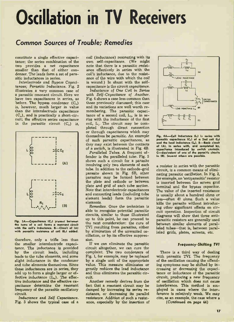
Parallel Condensers. The danger of spurious oscillation always lurks in instances where one condenser shunts another (see Fig. 1). The ca-pacitances of the two condensers
16
Oscillation in TV Receivers Common Sources of Trouble; Remedies
constitute a single effective capaci-tance; the series combination of the two provides a net capacitance smaller than that of either con-denser. The leads form a set of para-sitic inductances in series.
/nterlectrode and Bypass Capaci-tances; Parasitic Inductance. Fig. 2 illustrates a very common case of a parasitic resonant circuit. Here we have two capacitances in series, as before. The bypass condenser (C„) is, however, much larger in value than the interelectrode capacitance (Cs), and is practically a short-cir-cuit; the effective series capacitance in the parasitic circuit (Ce) is,
e
M Rc
Fig. 3A—Capacitance lCol present between the turns of a coil forms a resonant circuit with the coil's inductance. B—Circuit of (A) with parasitic resistance of coil (R,) added.
therefore, only a trifle less than the smaller interelectrode capaci-tance. The inductance is provided by the circuit leads, including leads to the tube elements, and some slight inductance in the condenser and tube elements themselves. Since these inductances are in series, they add up to form a single larger or ef-fective inductance (Le). The effec-tive inductance and the effective ca-pacitance determine the resonant frequency of the parasitic oscillatory circuit. Inductance and Self Capacitance.
Fig. 3 shows the typical case of a
coil (inductance) resonating with its own self-capacitance. (We might note that there is a parasitic resist-ance effectively in series with the coil's inductance, due to the resist-ance of the wire with which the coil is wound.) In shunt with the self-capacitance is the circuit capacitance. Inductance of One Coil in Series
with Self-Capacitance of Another. Fig. 4 shows a case less common than those previously discussed; this case and its variations are well worth re-membering. The parasitic capaci-tance of a second coil, L„ is in se-ries with the inductance of the first coil, Li. The circuit may be com-pleted through direct connection or through capacitances which may themselves be parasitic. An example of such parasitic capacitances, as they may exist between the contacts of a switch, is illustrated in Fig. 4B.
Paralleled Tubes. A frequent of-fender is the paralleled tube. Fig. 5 shows such a circuit for a parasite involving only two elements of each tube. In addition to the cathode-grid parasite shown in Fig. 5B, other parasites may be formed between the plate and cathode or between plate and grid of each tube section. Note that interelectrode capacitances and connecting leads (including tube element leads) form the parasitic elements. Remedies. Once the technician is
able to recognize potential parasitic circuits, similar to those illustrated up to this point, he can proceed to the next consideration: the cure of TVI resulting from parasites, either by elimination of the unwanted os-cillation, or by. its effective suppres-sion.
If we can eliminate the parasitic circuit altogether, we can cure the complaint. The two condensers of Fig. 1, for example, may be replaced by a single unit of the appropriate value. This measure eliminates or greatly reduces the lead inductance and thus eliminates the parasitic cir-cuit. Another remedy derives from the
fact that a resonant circuit may be damped by increasing its series re-sistance, or decreasing its parallel resistance. Addition of such a resist-ance, especially by the insertion of
Fig. 4A—Coil Inductance (L) in series with parasitic capacitance (C,) of a 2nd coil (1.,) and the lead inductance ILL B—Basic circuit of (A), in series with, and completed by, capacitance introduced by switch contacts. C—Equivalent of one of the parasitic circuits in MI. Several others are possible.
a resistor in series with the parasitic circuit, is a common means of elimi-nating parasitic oscillation. In Fig. 2, for example, an antiparasitic' resistor is inserted between the screen grid terminal and the bypass capacitor. The value of the inserted resistance is usually about a hundred ohms or less—often 47 ohms. Such a value kills the parasite without introduc-ing other significant effects on cir-cuit operation. Inspection of circuit diagrams will show that these anti-parasitic resistors are generally used between similar elements of paral-leled tubes—that is, between paral-leled grids, plates, screens, etc.
Frequency-Shifting TVI
There is a third way of dealing with parasitic TVI. The frequency of the oscillation causing the offend-ing symptoms may be shifted by in-creasing or decreasing the capaci-tance or inductance of the parasitic circuit, producing a new frequency of oscillation which does not cause interference. This method is em-ployed in cases where the inter-ference is relatively weak. We may cite, as an example, the case where a
(Continued on page 44)
17

Eliminating Television Practical Methods of Attack on Spurious Oscillation
Fig. 1 A—Schematic sketch of aft feedback loop. B—Parasitic circuit formed by the two ceramic capacitors used to replace C-1. C— Circuit of 1111 showing leads as inductances.
Fig. 2—Photo of two ceramic capacitors used to replace C-1 (schematically shown in 111).
Fig. 3A—Portion of horizontal output tube circuit. B—Parasitic that may develop here.
By J•ms A. Matomarrs • In this treatment of parasitic oscillation, we will consider some typical case histories. Before this is done, however, it would be well to sum up some pertinent points on this phenomenon.
Parasitic oscillation produces the same aural and visual symptoms as any other interfering signal. The TVI must first be proven to originate in the receiver, rather than outside of it. Further localization by an ex-ploring probe in conjunction with a signal tracing set will localize the trouble to a definite area of the chassis. The technician must inspect the
chassis, as well as study the set sche-matic, to help him determine whether parasitic or ordinary oscillation is present. Just as a chess player visualizes moves, the technician must visualize parasitic circuits that do not appear on his schematic. Typical cases of parasites are those
due to paralleled condensers, paral-leled tubes, paralleled interelectrode capacitances, parasitic self-capaci-tance, parasitic capacitance of one coil in series with another coil's in-ductance, and combinations of the preceding. Remedies consist of elimi-nation of the parasitic resonant cir-cuit, over-damping by the addition of resistance, reduction of transmis-sion and/or radiation, frequency shifting to an unused channel or band, excitation reduction, and com-binations of these procedures.
Case of the Paralleled Condensers. The first serviceman to work on this set had pulled the chassis, which was subsequently serviced in the shop. The finding was that C-1, a 390 mmfd capacitor (see Fig. 1A) was short-circuited. Since no 390 mmfd condenser was in stock, two capacitors of 100 and 180 mmfd, respectively, had been tied in paral-lel, and inserted in place of the origi-nal unit—a common enough practice. Replacement of C-1 with the equiva-lent condenser combination shown in Fig. 2 had resulted in normal opera-tion on all channels except Channel 11. Heavy bars appeared in the pic-ture at this channel setting.
The author, who didn't learn about these doings until some time after he had located the trouble, was next called in to service the set. Other sets, it was discovered, did not ex-hibit the TVI present on the receiver being serviced when they were con-nected to the same antenna and power line. The conclusion was therefore reached that the source of the TVI lay inside the set. Our second step was to signal-
trace the TVI to the area where its intensity was maximum, as indicated on another set used as a signal tracer, in conjunction with a signal-tracing probe. The "dog" and the tracer were
turned on. ("Dog" refers to the set with the TVI trouble; tracer refers to the auxiliary TV set with probe and cable used as a TVI locater, as described in Tracking Down TVI to its source, in the article begin-ning on page 14. The rear end of the probe cable was connected to the antenna of the tracer. The probe was placed near the feed from the mixer to the video i-f, to pick up the inter-ference, as well as the Channel 11 signal on which the interference ex-isted. Exploring with the probe by mov-
ing it about gave increasing inter-ference on the tracer screen as the probe came into the vicinity of the flyback transformer, the afc section and the afc feedback lead (see Fig. IA). The ground clip of the probe was now attached to the chassis, to reduce probe pickup and thus permit a more precise determination of where the intensity of the TVI was greatest. The search for the point of maximum intensity was narrowed down to the locality where the two. parallel condensers had been in-stalled. The replacement of these two units with a single capacitor re-sulted in the elimination of the para-sitic circuit that the two condensers, in conjunction with their pigtails, had formed (see Fig. 1B, C).
Parasite at Horizontal Output Tube Screen Grid. Fig. 3A illustrates this (horizontal) circuit; in 3B, the para-sitic components are schematically shown. The inductance of the bypass
18

Interference Due to Parasitics in Sweep, Sync and Other Circuits. Case Histories
condenser leads, tube and socket lead inductances, etc., provide the in-ductance of the resonant circuit present, while the effective capaci-tance is approximately the screen grid-to-cathode capacitance. Symptoms of the interference pro-
duced by such a parasite are gen-erally vertical bars at the left hand side of the raster—the most in-tense bar being farthest to the left, with succeeding bars of lesser in-tensity, at uniform spacings. The in-terference appears on all channels, as its frequency is approximately 25 mc. The second harmonic of this TVI signal may cause trouble on newer sets with 40 mc video i-f stages.
If this form of TVI is not readily identified by its appearance, the signal tracing procedure previously cited will unmask it. The ring or oscillation present is started by the sudden cutoff of the screen grid cur-rent of the tube at the onset of hori-zontal retrace, which periodically re-starts the in-phase oscillation. The typical cure for these cases of
parasitics due to interelectrode ca-pacitance is the insertion of a resist-ance in series with the parasitic cir-cuit, at the point indicated in Fig. 3A. (In many recent sets, a 47-ohm anti-parasitic resistor has been incorpo-rated into the circuit at the factory.) This antiparasitic resistor prevents oscillation by overdamping the cir-cuit. Excessive drive may cause such a
parasitic to occur. The overdriving may be the result of another trouble such as an old tube, excessive tube loading due to condenser leakage, etc., necessitating increased drive to maintain deflection and high voltage. The insertion of an antiparasitic resistor (when one is not already present) will suppress parasitic oscil-lation in such instances; removal of the primary trouble is, however, a better service procedure. The preceding discussion applies
with equal force to all cases of in-terelectrode capacitances paralleling circuit capacitances. Parasites may appear at the grid and plate of the horizontal output tube, for example. Other tubes may harbor a parasite if a parasitic circuit is present and
the excitation is great enough. In two instances the author knows
about, oscillation in the horizontal output tube was due to feedback from a parasitic plate or screen cir-cuit, to a parasitic grid circuit. The oscillation in the horizontal output tube, interestingly enough, furnished sufficient grid drive to the tube it-self to enable it to function without the horizontal oscillator. Both high voltage and horizontal deflection were present, although the deflection was not synchronized. The cure con-sisted, of course, of inserting an an-tiparasitic resistor in the grid cir-cuit.
Parallel Tubes. Whenever a tube is placed in parallel with another one to provide additional output, anti-parasitic resistors are or should be inserted in the leads between the plates, screen grids and control grids of the two tubes. Otherwise a pair of these elements may form a com-plex parasitic circuit with the cath-odes. As an example, consider the two 6BG6G's strapped together to form a parallel circuit in Fig. 4A. Fig. 4B shows the parasitic circuit. Present in this circuit are the screen-to-cathode capacitances of the two tubes; the leads between screen grids plus the internal screen leads form one inductance, while a similar in-ductance is made up of the cath-ode-to-cathode lead, plus the inter-nal tube leads to the two cathodes.
Similar parasitic trouble may de-velop due to grid-to-cathode and connecting lead capacitance, in which case resistor insertion in the grid-to-grid lead is proper. Similarly, the plate circuit may develop a parasite; a resistor in the plate-to-plate lead is employed to prevent this. Usual practice places a resistor in each lead excepting the cathode-to-cathode lead, although one may be placed here; the points where the resistors go are marked "x" in Fig. 4A.
All paralleled tubes should be ob-jects of suspicion relative to possible parasitics if the precautionary anti-parasitic resistors are not present. (Even when they are present, they may have decreased in value and should be checked, if a parasite
TURC TORE 2 Lea,sTe.L. SCREEN ORKI LEM) INDUCTANCE
0001-
TUNE CAPACITANCE -
CATNO0C-LEM) INDUCTANCE
1 TO STERNAL
CIRCuiT
IA)
Fig. 4A—Simplifled circuit of two tubes in parallel. Antiparasitic resistors are inserted at points indicated by X. B—Circuit of (Al re-drawn to show parasitic network present.
Fig. 5A—Section of sync circuit. B—Parasitic circuit of (AL Cp-k and Cg-k are the plate-cathode and grid-cathode capacitances.
Fig. 6—Photo illustrating circuit components shown in Fig. 5. Large condenser is C-1.
19

Eliminating TVI seems to exist in the circuit.—Ed.) Paralleled audio output tubes have also been frequent offenders, as have been push-pull oscillators, or paral-leled oscillators. Sync Circuit Parasite. Illustrative
of another complex case of parasitic oscillation, is the sync circuit shown in Figs. 5 and 6. The tube is a dual-section 12AT7 employed as sync am-plifier-clipper. The TVI produced by the parasitic was noticeable as a mottled bar effect on Channel 7 only. (The parasitic signal was apparently beating against the Channel 7 picture carrier to produce a beat-note of ap-proximately 4 mc.) The interference appeared when the customer moved to a new location.
Localization tests via signal trac-ing led to the area shown in Fig. 6 becoming suspect. Signal tracing also indicated that the wires passing under condenser C-1 through the metal grommet were "hot"—i.e., they had picked up the TVI from the parasitic circuit by capacitance coupling between them and C-1. The wires were, in turn, radiating the signal to the antenna lead-in to the tuner, on the opposite side of the chassis. The cure for this parasite con-
sisted- of lengthening the condenser leads, to provide additional parasitic inductance. One lead was made into a one-turn coil for this purpose. The resultant increase in inductance de-creased the parasitic resonant fre-
quency so that the beat note fell be-low *Channel 7. This is an example of frequency-shifting to an unused channel or band, to eliminate para-sitic effects. As a further precaution, condenser
C-1 was dressed at right angles to the chassis (it is shown in Fig. 6 as parallel to the chassis), and away from the wires under it, which acted as transmission lines when they picked up the resonant circuit's energy.
In some cases, the filament or heater wires leaving a tube carry the TVI with them. A bypass to ground with or without a series choke may help. In the case just cited, the re-duction in symptoms was so slight when such a remedial measure was tried, that filament bypassing was not added.
Filament Choke and Its Parasite. The photograph in Fig. 7 shows a filament or heater choke which formed the principal inductance of a parasitic circuit. The parasite be-came noticeable when the customer moved to a weak-signal area. The frequency fell within the i-f band, causing TVI on all channels that were relatively weak. Localization of the fault was effected by using a signal-tracer set and probe. The cure comprised replacement of
the choke with one having about four more turns; this procedure low-ered the resonant frequency below the i-f band. As an additional pre-caution (and to eliminate a trace of TVI on Channel 4 when the new choke was installed) a parallel re-
Fig. 7—Photo showing circuit in which filament choke contributed to a parasitic.
sistance was installed. This resistor of 150 ohms, inserted in parallel with the choke (and its shunt capacitance) provided overdamping in addition to the frequency shift. The case history just described il-
lustrates an important point, viz., check to see if you have created new TVI whenever you try to mini-mize or eliminate TVI by the fre-quency-shifting technique. Miscellaneous Cases. A capacitance
tuner with a band-switch for high and low channels in a Pilot electro-statically-deflected set (see Fig. 8) exhibited a parasite on the high-fre-quency band. The self-capacitance of the low-frequency oscillator coil,
Fig. 8A—Schematic of section of tuner circuit. 8—Parasitic circuit of tuner shown in (A).
in series with the inductance of the high-frequency coil and the self-capacitance of the band-switch con-tacts and the wiring, was forming a parasitic circuit. Frequency shifting was used to remedy the trouble. The shunt capacitance was varied
by moving the shunt trimmer on the low-frequency coil slightly, but suf-ficiently to shift the TVI beyond the point where it could produce inter-ference on the h-f band. The low frequency tuning was restored to normal by another adjustment, that of the inductance slug. The dial cali-bration was sufficiently broad to per-mit this procedure. Note that the self-capacitance of the low frequency coil is in shunt with the trimmer ca-pacitance on that coil, which ex-plains why the TVI frequency could be shifted by resetting this trimmer.
In another case, the heater "hot" leg of a 6J6 oscillator tube was by-pass'ed to ground by a condenser. The inductance formed by the heater itself, plus that of the wiring and ele-ment leads, produced a parasitic cir-cuit. The cure was a change in the value of the bypass condenser, which shifted the frequency of the TVI, making symptoms invisible.
20

Ringing Problems in TV Sets BY JAMES M CROBERTS
• Ringing circuits embrace all net--works which oscillate or ring due to shock excitation. Television receiv-ers employ the ringing circuits in some horizontal oscillator circuits (multivibrators and blocking oscil-lators) under several aliases: oscil-lator coil, stabilizer, phasing coil, etc.
Signal excitation usually causes rings in the peaking coils of video amplifiers. The resonant circuit of the peaking coils includes parasitic circuit capacitance (not shown on schematic) and interelectrode tube capacitances; hence, peaking coil circuits might also be classified as parasitic oscillatory circuits. Other television circuits, such as those in which the horizontal deflection coils lie, may also be placed in this cate-gory, due to their ability to resonate with their self-capacitance and pro-duce excessive amounts of ringing. The technician is concerned with
how such circuits oscillate, practical means for increasing or decreasing the intensity of the ring or oscilla-tion, and ways of suppressing the ring completely.
Simple Ringing Circuit. The sim-ple series-resistance ringing circuit of Fig. 2 is derived from the multi-vibrator circuit shown in Fig. 1. The reader will recall that multivibrator and blocking oscillator tubes act like switches, that is, these tubes change
very rapidly from no conduction (open-circuit condition resembling an open switch) to full conduction (closed switch condition). The tube's plate-to-cathode resistance is in series with the switch (Fig. 2B). The plate load resistor is in series with the plate resistance and the switch, and we are therefore justified in adding these together to form resist-ance Rx in Fig. 2A. We may liken the incoming sync
pulses shown in Fig. 1 to a mechanical arm attached to switch SW of Fig. 2A. The analogy may also be thought of with respect to Fig. 2B. The internal resistance of coil L in Fig. 1 becomes series resistance R in Fig. 2A. Ca-pacitance C in Fig. 2A comprises shunting capacitor C-1 shown in Fig. 1, plus the self-capacitance (not shown) of coil L.
Analysis of Series Ringing Circuit. Having simplified the circuit of Fig. 1 to the one shown in Fig. 2A, we may proceed to analyze its opera-tion. For the benefit of those readers who are not familiar with the sub-ject of ringing, we will further sim-plify Fig. 2A by considering that R is absent (R can never be eliminated in actual practice, it should be noted). We assume at the outset that switch SW is closed, permitting bat-tery B to send a current through the coil L, and to charge condenser C. Opening the switch causes this
passage of current through coil L to cease. The current that previously
Fig. 1—Section of horizontal multivibrator circuit. L and C-1 make up the ringing circuit.
V- I 1/2 6SN7-GT HOR.OSC. SYNC SIGNALS 6
NORMAL WAVEFORM AT PIN 5
C-1
RL JHOR. HOLD CONTROL
L.
R IS INSERTED B4. HERE IN SOME CASES
3
V-2 V26SN7-GT HOROSC.
Fig. 2A—Simple ringing network (L, C, and associated circuit. R is macle up chiefly of the resistance of the coil winding. B—Equiva-lent circuit of triode-switch tube. Grid-cathode voltage acts like a mechanical switch-ing arm that opens or closes the switch.
passed through coil L stored up en-ergy in the coil in the form of a magnetic field around it. This mag-netic field now tries to dissipate it-self, or collapse. In so doing, it sends a current through the circuit in a direction opposite to the one which originally flowed there. This new current charges C in the opposite direction. When the coil has transferred its
energy to C (storing a charge on C), the condenser will discharge, send-ing a current through L in the same direction as that of the original cur-rent. This recreates the field that originally appeared around coil L, and causes C to acquire a charge whose polarity is the same as the initial charge developed across it. One cycle of oscillation is thus com-pleted. This cycle repeats itself (see Fig. 3A).
Since R (Fig. 2A) is assumed to be absent, and no energy is dissi-pated in the coil or condenser in this hypothetical case, each succeeding cycle is an exact duplicate of the first one. We call this the undamped case, due to the fact that no resist-ance is present to damp out the os-cillatory energy. This theoretical case is approached in practice only in some extremely high "Q" circuits
21
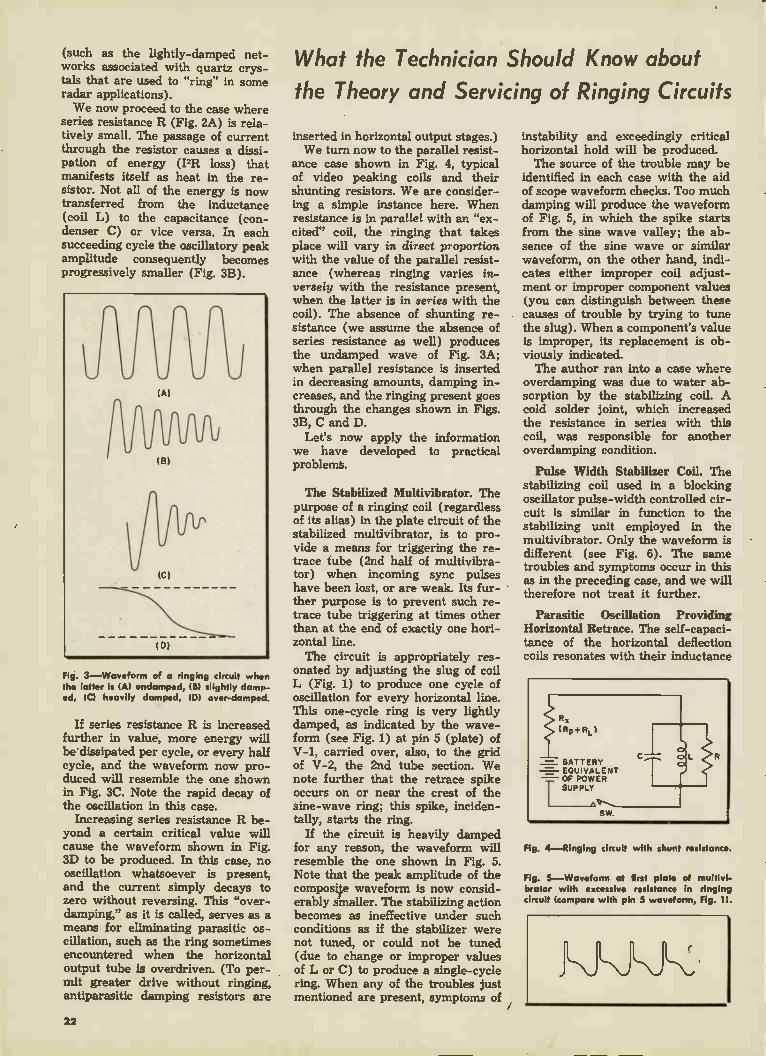
(such as the lightly-damped net-works associated with quartz crys-tals that are used to "ring" in some radar applications). We now proceed to the case where
series resistance R (Fig. 2A) is rela-tively small. The passage of current through the resistor causes a dissi-pation of energy (PR loss) that manifests itself as heat in the re-sistor. Not all of the energy is now transferred from the inductance (coil L) to the capacitance (con-denser C) or vice versa. In each succeeding cycle the oscillatory peak amplitude consequently becomes progressively smaller (Fig. 3B).
Fig. 3—Waveform of a ringing circuit when the latter is (Al undamped, slightly damp-ed, (a heavily damped, (D) over-damped.
If series resistance R is increased further in value, more energy will be dissipated per cycle, or every half cycle, and the waveform now pro-duced will resemble the one shown in Fig. 3C. Note the rapid decay of the oscillation in this case.
Increasing series resistance R be-yond a certain critical value will cause the waveform shown in Fig. 3D to be produced. In this case, no oscillation whatsoever is present, and the current simply decays to zero without reversing. This "over-damping," as it is called, serves as a means for eliminating parasitic os-cillation, such as the ring sometimes encountered when the horizontal output tube is overdriven. (To per-mit greater drive without ringing, antiparasitic damping resistors are
What the Technician Should Know about
the Theory and Servicing of Ringing Circuits
inserted in horizontal output stages.) We turn now to the parallel resist-
ance case shown in Fig. 4, typical of video peaking coils and their shunting resistors. We are consider-ing a simple instance here. When resistance is in parallel with an "ex-cited" coil, the ringing that takes place will vary in direct proportion with the value of the parallel resist-ance (whereas ringing varies in-versely with the resistance present, when the latter is in series with the coil). The absence of shunting re-sistance (we assume the absence of series resistance as well) produces the undamped wave of Fig. 3A; when parallel resistance is inserted in decreasing amounts, damping in-creases, and the ringing present goes through the changes shown in Figs. 3B, C and D.
Let's now apply the information we have developed to practical problems.
The Stabilized Multivibrator. The purpose of a ringing coil (regardless of its alias) in the plate circuit of the stabilized multivibrator, is to pro-vide a means for triggering the re-trace tube (2nd half of multivibra-tor) when incoming sync pulses have been lost, or are weak. Its fur-ther purpose is to prevent such re-trace tube triggering at times other than at the end of exactly one hori-zontal line. The circuit is appropriately res-
onated by adjusting the slug of coil L (Fig. 1) to produce one cycle of oscillation for every horizontal line. This one-cycle ring is very lightly damped, as indicated by the wave-form (see Fig. 1) at pin 5 (plate) of V-1, carried over, also, to the grid of V-2, the 2nd tube section. We note further that the retrace spike occurs on or near the crest of the sine-wave ring; this spike, inciden-tally, starts the ring.
If the circuit is heavily damped for any reason, the waveform will resemble the one shown in Fig. 5. Note that the peak amplitude of the composite waveform is now consid-erably smaller. The stabilizing action becomes as ineffective under such conditions as if the stabilizer were not tuned, or could not be tuned (due to change or improper values of L or C) to produce a single-cycle ring. When any of the troubles just mentioned are present, symptoms of
instability and exceedingly critical horizontal hold will be produced. The source of the trouble may be
identified in each case with the aid of scope waveform checks. Too much damping will produce the waveform of Fig. 5, in which the spike starts from the sine wave valley; the ab-sence of the sine wave or similar waveform, on the other hand, indi-cates either improper coil adjust-ment or improper component values (you can distinguish between these causes of trouble by trying to tune the slug). When a component's value is improper, its replacement is ob-viously indicated. The author ran into a case where
overdamping was due to water ab-sorption by the stabilizing coil. A cold solder joint, which increased the resistance in series with this coil, was responsible for another overdamping condition.
Pulse Width Stabilizer Coil. The stabilizing coil used in a blocking oscillator pulse-width controlled cir-cuit is similar in function to the stabilizing unit employed in the multivibrator. Only the waveform is different (see Fig. 6). The same troubles and symptoms occur in this as in the preceding case, and we will therefore not treat it further.
Parasitic Oscillation Providing Horizontal Retrace. The self-capaci-tance of the horizontal deflection coils resonates with their inductance
Fig. 4—Ringing circuit with shunt resistance.
Fig. 5—Waveform at erst plate of multivi-brator with excessive resistance In ringing circuit (compare with pin 5 waveform, Fig. H.
22
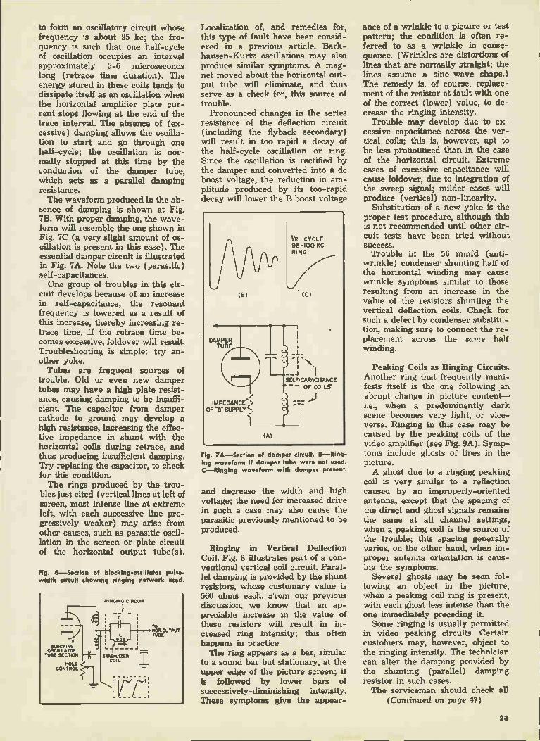
to form an oscillatory circuit whose frequency is about 95 kc; the fre-quency is such that one half-cycle of oscillation occupies an interval approximately 5-6 microseconds long (retrace time duration). The energy stored in these coils tends to dissipate itself as an oscillation when the horizontal amplifier plate cur-rent stops flowing at the end of the trace interval. The absence of (ex-cessive) damping allows the oscilla-tion to start and go through one half-cycle; the oscillation is nor-mally stopped at this time by the conduction of the damper tube, which acts as a parallel damping resistance. The waveform produced in the ab-
sence of damping is shown at Fig. 7B. With proper damping, the wave-form will resemble the one shown in Fig. 7C (a very slight amount of os-cillation is present in this case). The essential damper circuit is illustrated in Fig. 7A. Note the two (parasitic) self-capacitances. One group of troubles in this cir-
cuit develops because of an increase in self-capacitance; the resonant frequency is lowered as a result of this increase, thereby increasing re-trace time. If the retrace time be-comes excessive, foldover will result. Troubleshooting is simple: try an-other yoke. Tubes are frequent sources of
trouble. Old or even new damper tubes may have a high plate resist-ance, causing damping to be insuffi-cient. The capacitor from damper cathode to ground may develop a high resistance, increasing the effec-tive impedance in shunt with the horizontal coils during retrace, and thus producing insufficient damping. Try replacing the capacitor, to check for this condition. The rings produced by the trou-
bles just cited (vertical lines at left of screen, most intense line at extreme left, with each successive line pro-gressively weaker) may arise from other causes, such as parasitic oscil-lation in the screen or plate circuit of the horizontal output tube(s).
Fig. 6—Section of blocking-oscillator pulse-width circuit showing ringing network used.
Localization of, and remedies for, this type of fault have been consid-ered in a previous article. Bark-hausen-Kurtz oscillations may also produce similar symptoms. A mag-net moved about the horizontal out-put tube will eliminate, and thus serve as a check for, this source of trouble. Pronounced changes in the series
resistance of the deflection circuit (including the flyback secondary) will result in too rapid a decay of the half-cycle oscillation or ring. Since the oscillation is rectified by the damper and converted into a de boost voltage, the reduction in am-plitude produced by its too-rapid decay will lower the B boost voltage
Fig. 7A—Section of damper circuit. B—Ring-ing waveform if damper tube were not used. C—Ringing waveform with damper present.
and decrease the width and high voltage; the need for increased drive in such a case may also cause the parasitic previously mentioned to be produced.
Ringing in Vertical Deflection Coil. Fig. 8 illustrates part of a con-ventional vertical coil circuit. Paral-lel damping is provided by the shunt resistors, whose customary value is 560 ohms each. From our previous discussion, we know that an ap-preciable increase in the value of these resistors will result in in-creased ring intensity; this often happens in practice. The ring appears as a bar, similar
to a sound bar but stationary, at the upper edge of the picture screen; it is followed by lower bars of successively-diminishing intensity. These symptoms give the appear-
ance of a wrinkle to a picture or test pattern; the condition is often re-ferred to as a wrinkle in conse-quence. (Wrinkles are distortions of lines that are normally straight; the lines assume a sine-wave shape.) The remedy is, of course, replace-ment of the resistor at fault with one of the correct (lower) value, to de-crease the ringing intensity. Trouble may develop due to ex-
cessive capacitance across the ver-tical coils; this is, however, apt to be less pronounced than in the case of the horizontal circuit. Extreme cases of excessive capacitance will cause foldover, due to integration of the sweep signal; milder cases will produce (vertical) non-linearity.
Substitution of a new yoke is the proper test procedure, although this is not recommended until other cir-cuit tests have been tried without success. Trouble in the 56 mmfd (anti-
wrinkle) condenser shunting half of the horizontal winding may cause wrinkle symptoms similar to those resulting from an increase in the value of the resistors shunting the vertical deflection coils. Check for such a defect by condenser substitu-tion, making sure to connect the re-placement across the same half winding.
Peaking Coils as Ringing Circuits. Another ring that frequently mani-fests itself is the one following .an abrupt change in picture content— i.e., when a predominently dark scene becomes very light, or vice-versa. Ringing in this case may be caused by the peaking coils of the video amplifier (see Fig. 9A). Symp-toms include ghosts of lines in the picture. A ghost due to a ringing peaking
coil is very similar to a reflection caused by an improperly-oriented antenna, except that the spacing of the direct and ghost signals remains the same at all channel settings, when a peaking coil is the source of the trouble; this spacing generally varies, on the other hand, when im-proper antenna orientation is caus-ing the symptoms. Several ghosts may be seen fol-
lowing an object in the picture, when a peaking coil ring is present, with each ghost less intense than the one immediately preceding it. Some ringing is usually permitted
in video peaking circuits. Certain customers may, however, object to the ringing intensity. The technician can alter the damping provided by the shunting (parallel) damping resistor in such cases. The serviceman should check all
(Continued on page 47)
23

By CYRUS GLICKSTEIN
• Some TV sets may not look like it, but it can be taken for granted that the wiring layout, especially in critical circuits, has been carefully planned by the engineering depart-ment. However, experience has shown that poor wiring (improper lead dress) does creep in, both in the initial manufacture and in sub-sequent servicing. This produces a wide variety of troubles. To emphasize the importance of
the subject, it might be noted that improper dress of leads, as well as incorrect placement of parts like re-sistors and condensers, can cause: 1) audio defects such as buzz and hum; 2) video defects such as a weak (snowy) picture, interference, regeneration, poor sync, bending, impaired interlace, and ragged edges on the raster; 3) circuit breakdown as a result of heat and arcing; and 4) interference with other receivers —for instance, AM home radios. As an aid in troubleshooting, the
above symptoms can be reclassified on a more useful basis. Proper lead dress is necessary (see Fig. 1) to avoid:
1) Breakdowns due to heat. 2) Breakdowns due to arcing or
corona. 3) Defective operation due to un-
wanted bypass action. 4) Defective operation due to un-
desired coupling between stages.
Each of the above classifications, together with the circuits usually affected, will be discussed in turn. Troubles in the first two cate-
gories are familiar to most service-men. Heat breakdowns can be avoided by routing leads away from hot tubes, resistors, or similar parts which may burn the insulation and eventually cause trouble. It is also necessary to place parts which be-come hot away from other parts (like condensers) that may change in value or break down more readily because of the heat. This does not mean that the rout-
ing of leads and the placement of small parts should be radically shifted around in every set that comes to the service bench. As will be seen shortly, this would siniply be asking for trouble, not preventing it. A good rule to follow is: if the set has been working ok prior to the breakdown, follow the original wiring and parts location as closely as possible in making the replace-ment, but avoid placing the new part and its connecting wires close to a hot spot. If a wire or part in
Lead Dress Problems Incorrect Placement
another section of the chassis is seen to be overheating because of its location, change the location, observing the precautions indicated in the next paragraphs.
Arcing Troubles
Arcing can be caused by defec-tive lead dress in either the low-voltage or the high-voltage circuits; the fault, however, usually occurs in the high-voltage circuit. In low-voltage supply circuits, servicemen are usually careful not to dress a B+ tie-point too close to chassis or a ground wire. Low-voltage B+ wires generally have adequate in-sulation, so there is no arcing even if they touch the chassis. In high-voltage circuits, there is a
much greater problem. Arcing can take place between points which are not touching if there is a large enough potential difference between them. In addition, corona (ionization of the air) may occur, particularly in the vicinity of a pointed or sharp-edged hv connection. The following rules summarize the
precautions which should be taken in high-voltage circuits: 1—Terminals of the high-voltage
rectifier socket should be dressed toward the inside of the corona ring and be free from sharp protrusions. 2—The corona ring should be
dressed so that it will function prop-erly; that is, centered, and about 1/8_ in. below the socket terminals. 3—All leads in the high-voltage
circuit should be kept as far apart from each other as possible. They should be short and direct, but with-out strain, and dressed as far as pos-sible from the flyback transformer windings. The leads should also be dressed as far as possible from the chassis, and away from low-voltage leads, or leads at or near ground potential. Particular precautions should be taken to keep the high-voltage rectifier and horizontal out-put plate-cap leads as far as possible from the cage (chassis). It is good practice to wax these leads at both ends, to minimize corona spray. 4—Make certain no sharp points
are present, after soldering replace-ment parts in the high-voltage cir-cuit, to minimize the possibility of corona. It is advisable to operate the
of Wiring Can Cause
receiver in a darkened room after completing the repair, checking for the smell of ozone or audible arcing. The next important type of trouble
caused by incorrect lead and com-ponent dress is defective bypass ac-tion. This is most likely in r-f, i-f and video amplifier circuits, and can result in defective output because of regeneration, reduced output, or poor high-frequency response.
In video amplifier circuits, coup-ling condensers and peaking coils are mounted away from the chassis to minimize stray capacitance to ground and possible reduction of high-frequency response.
In video i-f circuits, the leads of i-f coils (because of their length and position) become part of the circuit tuning. The distance of these leads from the chassis helps determine the amount of stray capacitance in the tuned circuit. When a video i-f coil is aligned to a given frequency, the capacitance of the lead dress be-comes an integral part of the circuit tuning. Changing the lead dress may therefore change the resonant fre-quency of the circuit. If done on a wholesale basis, the video i-f sec-tion may be sufficiently detuned to make realignment necessary.
Replacement Cautions
Special care must be exercised in replacing bypass condensers in r-f and i-f stages. It is advisable to use the same type of condenser, with the same pigtail length at both ends, as originally present. Furthermore, the condenser should be replaced in exactly the same position. A condenser in these circuits acts
not simply as a condenser, but rather as a tuned circuit. The capacitance of the condenser plus the stray capacitance of the pigtails to chassis, together with the inductance of the pigtails, plus the inductance intro-duced by the internal construction of the condenser, all combine to make any capacitor a resonant cir-cuit at some particular frequency. This affects the bypass action of the condenser at the desired frequencies, and in turn the frequency response of the stage. Changing the type of condenser and its pigtail length may change the response of the stage with which it is associated, possibly caus-
24

in Television Receivers Buzz, Hum, Poor Interlace, Improper Holding, and Other Symptoms
ing some degeneration of the incom-ing signal, or regeneration, because of a peak in the response. In addi-tion, failure to replace the part in its previous position may introduce other problems, which we are going to discuss shortly. It is important to use the same ground points when re-placements are soldered in. To summarize, don't disturb lead
dress in r-f and i-f circuits unless there is a reason (say, elimination of undesired coupling) for doing so. When leads must be moved, keep this caution (which applies to all circuits) in mind: When moving leads to find out if they are causing undesired coupling, don't move them around at random. Move only those leads that can possibly cause the defect. Then, if the trouble is not eliminated, return them to their origina/ position. The largest group of lead dress
troubles is probably caused by coup-ling. An unwanted signal may be coupled from one circuit to another capacitively (adjacent wires or parts can form the plates of a condenser, functioning like a conventional coupling condenser); inductively (ac voltages in one wire may induce a voltage in an adjoining one) or both. In some cases, a signal may be ra-diated from one circuit into another one. Because of the many possible de-
fects caused by coupling, this condi-tion will be discussed under a) audio effects and b) video effects. The most common audio troubles
caused by improper lead dress are hum and buzz. Since each of these defects may also be caused by other faults, it is important to narrow down the possible sources of trouble before starting to shift leads around.
Troubleshooting Procedure
A suggested troubleshooting pro-cedure to determine whether hum in the sound is due to lead dress may be roughly outlined as follows: First, note if the hum is heard on all chan-nels. If it is, turn the volume control to minimum. If the hum is still heard, the most likely source of trouble is either the low-voltage power supply or an audio tube (in which cathode-to-heater leakage is present). If the hum, on the other hand, is elim-
inated by turning the volume control down, turn the control up about half way, so the hum can be heard. Now short the "hot" terminal of the volume control to ground. If the hum is still heard, it is no doubt be-ing picked up by the leads to the first audio stage (from the volume control, tone control, etc.).
Carefully move the suspect leads, noting whether hum increases or decreases. If these leads are near filament or line input wires, reroute the appropriate wires, if necessary. In general, ac leads are kept close to the chassis, and away from circuits particularly susceptible to pickup, or whose operation may be affected by pickup. In redressing audio leads to reduce
hum, be careful to avoid buzz pickup and regeneration. Regeneration (which often manifests itself as a high-pitched squeal) can result from placing the plate lead of the audio output stage too close to the grid lead or grid circuit of the first audio stage. When it is not possible to entirely
eliminate hum pickup by redressing the leads, it may prove helpful to shield (unshielded) leads going to the volume control and the first audio stage. When a shield is added, not more than 1/4 in. of wire should extend from each end of the shield. Both ends of the shield should be
well grounded. If hum is heard on only one or a
few channels, try placing a .01 mfd ceramic or mica condenser across the antenna terminals. If this re-duces the hum, it is probably being fed into the tuner. The first likely thing to check in this case would be the age tube and its associated circuit. Buzz may have many different
causes. Common classifications of buzz include sync pulse pickup. intercarrier buzz, vertical sawtooth pickup, and mechanical vibration of laminations in a vertical sweep or power transformer. To determine whether the buzz is caused by the vertical circuit, vary the vertical hold control. If a change in the pitch of the sound is now heard, then the buzz is originating in the vertical circuit.
Tracing Source of Buz;
If there is any question whether. the buzz is coming directly from the speaker, or indirectly from a transformer in the vertical sweep circuit, turn down the volume con-trol completely. If the buzz is still audible, it is no doubt being caused by the mechanical vibrations of a vertical transformer (blocking os-cillator or output). To eliminate the vibration, crimp the lamination
(Continued on page 44)
Fig. 1A—Placing wires or components too close to units that generate heat, such as high-current tubes or large resistors, invites subsequent breakdowns. B—When an hv lead is too near a ground point, arcing or corona is likely to occur. C—Dressing a video peaking coil too close to chassis will Introduce an undesired bypassing effect. D—Undesired coupling between leads.
HOT TUBE
(Kr
CONDENSER OVERHEATS
NIGH-WATTAGE RESISTOR
VIDEO PEAKING COIL TOO CLOSE TO CHASSIS
le)
-4--CHASSIS
WIRE1
GROUND
04-•—•ANG
N V LEAD
WIRJ„...1 WIRE-. WIRE
I- II( (D)
CAPACITAT IV E INDUCTIVE COUPLING COUPLING
tVIRE
COUPLING VIA RADIATION
25

Eliminating Tweet Interference Some Suggestions on Lead Dress Troubles
BY CYRUS GLICIESTEIN
The most important video defect which can be caused by lead dress is tweet—an r-f interference pat-tern generated internally in the re-ceiver. The tweet frequency i§ a harmonic of the video or sound i-f carrier. This harmonic is fed from the video detector back to the tuner, beats with the incoming picture or sound r-f carrier, and causes an interference pattern to be visible on the screen. The tweet pattern is usually a
continuously changing one. It can generally be distinguished from ex-ternal interference by a simple test. Vary the fine tuning control. If the TITI pattern seen changes from thin diagonal or vertical lines, to broad horizontal lines, and back to diagonal lines, as the fine tuning is slowly varied (see photos), the interference pattern is probably due to an internally-generated tweet. To verify this, figure out whether
any harmonic of either the sound or picture i-f is close in frequency to either the sound or video r-f carrier, on the channel (s) where the interference is present. If it is, a tweet is probably the cause of the TVI.
In most cases, the tweet is caused by pickup of the i-f harmonic in the section of transmission line between the antenna terminals and the tuner. The trouble may be due to the in-sufficient spacing of this antenna lead-in from audio or video i-f
stages, particularly the video detec-tor. If moving the lead-in reduces the tweet symptoms seen on the screen, it is advisable to staple the lead-in along the top of the cabinet, as far from the video i-f section as possible. It may be necessary to lengthen the lead-in, to obtain the maximum reduction in interference.
If the tweet is not caused by pickup in the antenna lead-in, it is advisable to determine whether it is originating in the sound or video i-f section. This can be done, as de-scribed previously, by simply check-ing mathematically — determining whether the sound or video i-f har-monic falls in the channel tuned in. Another check consists of removing the first sound i-f tube and noting if the tweet effect disappears. If it does, it is originating in the sound i-f section.
Possible procedures for clearing up tweet interference originating in the sound i-f section include the following:
a) Check sound i-f and discrim-inator transformer shield cans and wiring. The cans should be tight in place and well grounded to the chassis. b) Lead dress in the discrimina-
tor stage, especially that of discrim-inator transIormer wiring, should be short and direct.
c) All bypass capacitors in the sound i-f section should have leads as short as possible; the capacitors themselves should be dressed close to the chassis.
(Da
For clearing tweet interference originating in the video i-f section, the following is recommended:
a) Try shielding the 4th video i-f, video detector, and video ampli-fier stages, when such shielding is absent.
b) Wires from the video detector circuit should be short, dressed close to the chassis, and away from other wiring. cr Determine, by bridging and
resistance tests, whether bypass condensers in the 4th picture i-f plate circuit, the r-f bias circuit, and the video i-f plate and screen circuits are in good condition.
d) An outdoor antenna should be tried on receivers using built-in antennas, since the outdoor unit provides a better signal, less sus-ceptible to interference. A built-in antenna is apt to pick up more tweet interference than an outdoor one.
In the case of particular receiver models, where the tweet problem is present in aggravated form, service bulletins of the set manufacturer should be consulted.
TVL caused by tweet varies from narrow diagonal lines (left) to broad horizontal lines (right), as 1Ine tuning control is rotated slowly.
26

Fig. 1: Indoor TV antenna with end cops Is physically small, has large electrical volume
Switch Tuned UHF-VHF Antenna Indoor unit for TV reception achieves large electrical volume with minimum physical size. Circuit compensates for mismatch at different frequencies
By GUY HILLS Consulting Engineer Trierait Products Co. 1535 N. Ashland Ave.
Chicago 22, Ill.
The trend in indoor TV antennas the last few years has been to-
ward smallness and easily operated tuning means or the complete lack of any tuning adjustment. These two properties seem in demand even at the expense of considerable loss in performance. Regardless of the particular design
of the small antenna there is at least one fundamental limitation to which
MILL« Meng) jer IMO« FICIP
CND CAPI 5"
it is subject: its possible band width decreases very rapidly as its size is decreased. Its impedance can still al-ways be matched to say a 300 ohm transmission line at any one fre-quency but the match rapidly de-teriorates for frequencies different from that of good match. This means the antenna band width is small.
Wheeler shows that the possible band width varies as the 4th power of frequency for a constant small an-tenna size (and is proportional to the volume of space occupied by the antenna).
In order to construct an antenna that has as much volume electrically as possible yet is small physically the dipole with end caps, Fig. 1, was chosen. According to Wheeler's formulae
e..onsidering the antenna to consist of two condenser plates of the size and positions of the end caps of Fig. 1 an effective volume of 6,220 cubic inches is obtained. This is equivalent to that of a sphere of diameter 91% of the length of the antenna of Fig. 1. On the basis of this volume the theoreti-cal 6 db. band widths obtainable (ir-respective of the circuits used for matching) are shown in Table I. A 16: 1 voltage standing wave ratio in-dicates a 6 db. loss in transmission. Wheeler's formulae are for "small" antennae by which is meant antennae less than 1/2n times the wavelength as their greatest dimension. As the present 25-in, long antenna can therefore be considered small for fre-quencies less than 75 MC the theo-retical band widths of Table I for channels 5 and 6 are less accurate than the others but are given to show the trend. The measured band widths are al-
ways higher than the theoretical be-cause of inevitable heat losses. The band width of course could always
Fig. 2: Antenna with portion of outer covering cut away. Knob for rotating antenna eliminates need to grasp de-vice in region sensitive to hand capacity
Channel
Theoretical 6 db. Measured 6 db. band width band width
M. C. M. C.
2 2.0 6
3 3.0 6
4 4.3 7
S 7.5 15
6 10.3 18
7 to Antenna con no longer be considered 83 small—see VSWR curves
Table I: Theoretical and measured 6 db band-widths of antenna for UHF and VHF reception
be increased by the process of resis-tive damping the antenna, but only at loss of signal. The theoretical band widths of the antenna indicate that for an antenna of this size only one VHF channel can be covered well in the low end of the band without a tuning adjustment no matter how the antenna is designed.
Matching— Low VHF Band
It is theoretically possible to match any impedance to any other imped-ance at one frequency by use of only two elements (such as a coil and a condenser). Since a short dipole has an impedance equivalent to a small resistance in series with a small capacitance the problem is to tune out the reactance of the capacitance and transform the resistance up to 300 ohms so that the antenna im-pedance will be purely resistive and
(Continued on page 44)
27

Troubleshooting Vertical Fast Checks for Defective Tubes, Vertical Output Transformer,
By M . M. GERSHUNY
• The vertical deflection circuits of a television set are probably the simplest circuits to service in the re-ceiver. There are usually only two stages involved, both of which are relatively uncomplicated. An under-standing of some simple facts about these circuits should enable the tech-nician to service them with a mini-mum waste of time and parts.
Possible symptoms produced by defects in vertical deflection systems may be classified as follows: 1. Com-plete loss of vertical deflection; 2 In-sufficient height; 3. Foldover; 4. Loss of synchronization; 5. Distortion (non-linearity). Although it is entirely possible
that a single defect may cause more than one of the above symptoms to appear, it has been the writer's ex-perience in the majority of cases that one symptom alone has generally had to be dealt with. The vertical circuit shown in Fig.
1 is typical of many television sets in use today. Another circuit in common use is illustrated in Fig. 2. The troubleshooting suggestions for these circuits may be easily adapted to other similar ones. Let us consider the first possibil-
ity, complete loss of vertical deflec-tion. This problem involves two ap-proaches. One is the procedure of the serviceman in the customer's house, carrying a minimum of test
equipment and parts. The other is that of the benchman who has a wide assortment of equipment and parts readily available. The usual procedure in the cus-
tomer's house is to check the tubes in the vertical circuits by substitu-tion. Most cases of vertical trouble are due to defective tubes. In check-ing this circuit, it is desirable to re-place both oscillator and amplifier tubes at the same time; if the trou-ble disappears, replace the old tubes one at a time. In this way, if both tubes happen to be defective, they will be quickly found. Should the tube substitution test
prove inconclusive, the next logical procedure would be a check of the height and vertical linearity controls. (Some servicemen might prefer to check the setting of these controls before substituting tubes—Ed.) Each of these controls should be turned from one extreme to the other, while the CRT screen is observed, to de-termine whether the control action is normal. It is not too uncommon to find that a defect in one of these controls is responsible for a loss of vertical deflection. The same is true, of course, of the vertical hold con-trol. If one of the controls is found to be defective, an emergency repair can sometimes be made in the cus-tomer's home.
It will be found that, in most sets, potentiometers are used for vertical controls. Usually one side of the pot
Fig. 1—Typical vertical circuit using blocking oscillator. R-1 is height, R-2 hold control.
will be tied to the variable arm, or left unconnected. If the wire on one end of the defective pot is trans-ferred to the unused terminal, the circuit will frequently work quite satisfactorily. If the serviceman has an ohmmeter with him, this need not be a matter of guesswork.
Defective New Tubes
If the foregoing procedures do not bring desired results, the next log-ical procedure is to "pull" the chassis to the shop for repair. Once the chassis is set up on the bench, the experienced henchman will usually check the tubes again. All too often, the new tubes in the service kit are found to be defective. While checking the tubes, the
technician can also test the output transformer and yoke by rocking the output tube in its socket. If the disturbance makes the bright line on the CRT jump up and down (to-tal loss of vertical deflection is as-sumed), these components are prob-ably in good condition. If not, they should be first on your list of sus-pects. The amplifier stage can be rapidly
checked by placing a finger on its control grid. (Applying a 60-cycle hum signal through a .1 mfd con-denser would be a safer procedure —Ed.) The easiest way to do this is to hold a long, thin screw-driver by the handle, placing one finger on the blade; the tip of the blade is then touched to the grid pin. The AC
voltage picked up by your body is thus applied to the vertical ampli-fier; if the amplifier is functioning properly, some deflection will now be seen on the screen of the CRT. This will isolate the trouble to the oscillator, which can now be checked with a vacuum-tube voltmeter. The typical vertical oscillator has
comparatively few components, which simplifies the technician's job. Since the tube, vertical hold control and height control have already been tested, only a few components re-main to be checked.
If the preliminary test indicates trouble in the vertical output circuit, simple voltage checks at the plate and cathode of the output tube will speedily indicate the source of the de-
28

Deflection Circuits Yoke, and other Components. Troubles, Tests.
feet in most cases. On the rare oc-casions that, by the process of elim-ination, the yoke becomes suspect, the writer has found that the best check is to substitute another yoke. If one of the correct inductance is not available at the moment, any unit can be used, provided that it is kept in the circuit only long enough to verify the diagnosis. The problem of insufficient height
has plagued the serviceman since the onset of television. This trouble has two variations. One is the condi-tion in which, with height and line-arity controls fully advanced, the picture does not fill the screen. The other is the less obvious but equally annoying condition of being able to fill the screen, but only by severely distorting the picture. (The writer has noticed that the average person is much more disturbed by vertical than horizontal distortion.)
Tube Substitutions
The approach to this problem can be split up into field and shop tech-niques. The field technician is lim-ited, in the average service opera-tion, to tube substitution. In addition to replacing the oscillator and am-plifier tubes, the low-voltage recti-fier tube or tubes should be re-placed. If the set uses selenium rec-tifiers, these should be checked in the shop.
In some cases, where the amount of picture shrinkage is small, and ordinary substitution does not help, substitution of a different tube type may be worth trying. Types 6V6 or
6W6 have been successfully used in place of a 6K6 vertical amplifier to give just the extra bit of deflection needed. In circuits using a 6SN7 ver-tical amplifier, a 6BL7 has been used with good results. This practice is desirable only in
the field, in cases when the customer does not want to stand the expense of a shop repair. The set owner should, incidentally, be made aware of what has been done, and why. Over several years, the writer has never seen any ill effect resulting from this type of substitution. We must confess having encountered a small minority of cases where the method did not work.
If the problem proves too much for the outside serviceman, the benchman comes into the picture. He can simplify his problem by first inspecting a picture, or, preferably, a test pattern. The benclunan will find that either the height control or the vertical linearity control will lack sufficient range to bring the pic-ture into good linearity at the proper size. If the height control is found wanting, the trouble is most likely in the oscillator or the grid circuit of the output tube. If the vertical line-arity control does not have enough range, the trouble is in the cathode or plate circuit of the amplifier. A trouble commonly encountered
is a leaky coupling capacitor (C-3, Fig. 1; C-71, Fig. 2). This defect us-ually causes a compression at the bottom of the picture, and possibly a short foldover. One very confus-ing problem can be caused by a de-fective C-1 (Fig. 1). The writer has seen cases where, with C-1 partially
Fig. 2—Vertical deflection circuit using multivibrator as oscillator. Numbers at various circuit points refer to wave forms that appear at these points. Pertinent wave forms are illustrated in Fig. 4, on following page. Circuit is from an Emerson 120168-D television chassis.
shorted, the vertical sweep fre-quency went up to over 400 cycles per second. In addition to severe loss of height, the resulting jumble on the screen resembled a loss of hori-zontal sync. Only close inspection of the raster, showing uneven spac-ing of scanning lines, especially the oddly-rambling vertical retrace lines, gave a hint of the real trouble.
Vertical Amp. Tests
The output circuit of the vertical amplifier is best checked by sub-stituting parts. The author does not recommend substituting parts from junked sets for test purposes. If the vertical output transformer is not a good impedance match between the amplifier and the yoke, adequate height may not be attained. In the case of permanent replacement, it is a false economy to use any but an exact replacement part.
In many cases, where the height is almost, but not quite satisfactory, replacement of the vertical ampli-fier's plate decoupling and cathode bypass condensers (after a bridging test) will bring it up to par. Among the easiest symptoms to
recognize are some of those pro-duced by a defective yoke. When we have loss of height due to yoke trouble, a trapezoidal raster will al-most always be seen. When one side of the raster is noticeably different
C-O7 SYNC, SIP. my
R-111 150 II
•
.210 y 4.5)0
VERTICAL OSCILLATOR
V-111 SSNTGT
C-011 .0047 '7.
TO-1
11-01 47R
Co'. YO I r
11-0S R-110 100 NPR
R-114 1203
C-111 1.047
- VERT. 141X0 CONTR.
Os R-113
SWSQT VERT. SIZE
R-14 CONTROL 1 MEG.
3 C-70 .087
IMES), 11Z-111 I
RAO
C-11
' n-u :Es&
• C-n VERT. OUTPUT
V-111
C-71 100
• a..? 470
R-1N1 SR
VERT. LIN. CONTRIX
T-10
.11110e,
+110 V X-4 BOTTOM VIEW OP »CUT
P - 4
TO DAMPER CIRCUIT
DEFLECTION YORE ASSUISLY
s C-71 SEE îo,
1 og I.
L-I4 1 NC4112. I COILS
14
R-1011 310
1.-IS e VERT 'COILS
mg
29

in size from the other, look no fur-ther; replace the yoke. (It would seem wise to check components in parallel with yoke windings, before condemning the yoke—Ed.)
Vertical foldover is caused by dis-tortion in the vertical sawtooth wave applied to the deflection coils, or by a slow vertical retrace. In the first case there will be foldover at the bottom of the picture; in the sec-ond, a foldover will appear at the top. Bottom foldover can usually be cleared by replacing tubes. Some-times, an improperly-adjusted ver-tical linearity control will introduce foldover; the condition is, of course, eliminated by proper control adjust-ment. When vertical foldover seems
present, the settings of all vertical controls should be carefully checked. Sometimes, when the vertical oscil-lator locks in at an incorrect fre-quency, the picture looks as though it has a bad vertical foldover. Next to the tubes, the most com-
mon cause of foldover, in our ex-perience, is a leaky coupling capaci-tor. Even when leakage in C-3 (Fig. 1) is so slight that a resistance of several megohms is measured across it, an annoying foldover at the bot-tom of the picture is apt to be pro-duced. The best way to check this capacitor is to disconnect it at the grid of the output tube and meas-ure for DC voltage between the open side of the capacitor and ground. With a good capacitor, the meter may fluctuate around some low read-ing, no higher than about three volts. A bad capacitor will cause an ap-preciably larger reading. A leak in the charge-discharge capacitor (C-2, Fig. 1; C-70, Fig. 2) can cause a severe compression at the bottom of the picture, resembling a foldover. This condenser may be checked in the same manner as the coupling ca-pacitor. Foldover at the top of the picture
is relatively rare. It may be caused by an increase in the value of the peaking resistor (R-4, Fig. 1; R-92, Fig. 2), or a bad output transformer or yoke. Unfortunately many cus-tomers prefer to live with this condi-tion rather than pay for its cure.
When the all-too-frequent com-plaint, "The picture jumps," is heard, the experienced technician goes to the customer's house prepared for anything, from fixing the antenna to suggesting new glasses for the cus-tomer. There is probably no other television defect with as many pos-sible causes as unstable vertical hold. To mention just a few, this condition can be caused by electrical interference, incorrect antenna ori-entation, improper adjustment of the fine tuning control, and video Ir mis-alignment. We will discuss only de-fects in the vertical circuits which may be the cause of this condition.
Vertical Amp. Tests
Under the normal operating con-ditions, in the case of most televi-sion sets, the vertical sync pulses are separated from the horizontal ones by a low-pass filter—the integrating circuit. These pulses are fed to the vertical oscillator, and lock it into synchronization with the correspond-ing oscillator at the transmitter. The normal or free-running frequency of the vertical oscillator should be somewhat less than sixty CPS for op-timum control by the sync pulse. The oscillator's free-running frequency is adjusted by the vertical hold con-trol. The height control also has some effect on frequency; it should be possible to compensate for this effect by re-setting the hold control. There are three possible conditions
pointing to a defect in the vertical hold circuit. One would be the con-dition in which the vertical oscilla-tor is not locked in. The hold con-trol can be adjusted to approximately sixty CPS, but the picture continues to drift up or down. A second con-dition would be where the vertical hold setting does not bring the os-cillator close enough to sixty cycles to permit it to lock in. In this case, the picture can frequently be locked at a multiple of sixty cycles, or even at thirty cycles, depending on wheth-er the frequency is too high or too low. The third problem exists when the vertical oscillator fre-quency drifts, requiring readjust-ment of the hold control; eventually,
Fig. 3—Normal waveforms and their amplitudes in a typical vertical circuit using a blocking oscillator. A—Grid of vertical oscillator (135v p-p) 8—Plate of vertical oscillator (105v p-p) C—Grid of vertical output tube (105v p-p) D—Plate of vertical output tube (900v p-p) E—Cathode of vertical output tube (1v p-p). (Courtesy, RCA)
the drift in frequency is too great for hold control re-setting to correct, and condition two results.
It should be immediately appar-ent that the vertical sync pulse is not reaching the oscillator in the first condition described. If the picture is not out of horizontal sync at the same time, then the likeliest place for the pulse to be lost is the inte-grator. Since the fault is a sync rather than a vertical circuit defect, we will not discuss it further. For condition two—oscillator too
far out of range—the oscillator grid components (C-1, R-7 and R-2 in Fig. 1; C-69, R-90 and R-89 in Fig. 2) are the ones to check, since they control the oscillator frequency. The technician should note whether the picture is rolling up or down. If the picture rolls up, the oscillator fre-quency is less than sixty cycles. If it rolls down, the frequency is above sixty cycles. An increase in the time constant
of C-1, R-7, and R-2 would make the oscillator frequency too low. This is commonly caused by an increase in the value of the resistor in series with the hold control (R-7, Fig. 1). Conversely, an increase in oscillator frequency would be caused by a de-crease in the time constant just mentioned. This could very well be due to a loss in the capacitance of C-1 (Fig. 1). Condition number three (drift)
can usually be cured by replacing both C-1 and R-7 (Fig. 1). We have seen cases where a defect in the hold control was responsible for drift; this is, however, very unusual.
Distortion in the vertical direction is relatively rare. It can be caused by a defective vertical amplifier tube, or an open coupling capacitor. Strong hum in the B supply can cause ap-parent stretching and compression of the picture in the vertical direction. If the transmitter is powered from a different source than the receiver, the stretched and compressed areas will slide up or down, causing an ef-fect like trick mirrors at a carnival. The open capacitor can be found, of course, by successively bridging the different electrolytics in the B supply.
Fig. 4—Waveforms and their amplitudes in the circuit of Fig. 2 (preceding page). Numbers un-der the waveforms refer to the circuit points in Fig. 2 at which the waveforms were obtained.
ç / V't r /(/ ,-• ----,
P ,o P SOO P IMIIIMEM EUMINEEM ritrEMEM
• • • •
30
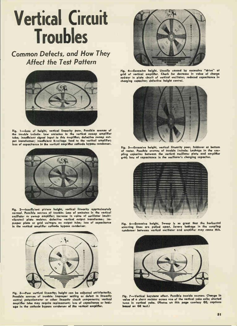
Vertical Circuit Troubles
Common Defects, and How They Affect the Test Pattern
Fig. 1—Loss of height, vertical linearity poor. Possible sources of the trouble include: Low emission in the vertical sweep amplifier tube; insufficient signal input to this amplifier; defective sweep out-put transformer; insufficient 8-voltage feed to the vertical amplifier; loss of capacitance in the vertical amplifier cathode bypass condenser.
Fig. 2—Insufficient picture height, vertica: linearity approximately normal. Possible sources of trouble: Loss of emission in the vertical oscillator or sweep amplifier; increase in value of oscillator (multi-vibrator) plate resistor; defective vertical output transformer; im-proper plate or grid voltages on output tube; loss of capacitance in the vertical amplifier cathode bypass condenser.
Fig. 3—Poor vertical linearity; height can be adiusted satisfactorily. Possible sources of trouble: Improper setting or defect in linearity control potentiometer or other linearity circuit components; vertical amplifier tube may require replacement; loss of capacitance or leak-
age in the cathode bypass condenser crf the vertical amplifier.
Fig. 4—Excessive height. Usually caused by excessive "drive" at grid of vertical amplifier. Check for decrease in value of charge resistor in plate circuit of vertical oscillator; reduced capacitance in charging capacitor; defective height control.
Fig. 5—Excessive height, vertical linearity poor, foldover at bottom of raster. Possible sources of trouble include: Leakage in the cou-pling capacitor between the vertical oscillator plate and amplifier grid; loss of capacitance in the oscillator's charging capacitor.
Fig. 6—Excessive height. Sweep is so great that the horizontal scanning lines are pulled apart. Severe leakage in the coupling condenser between vertical oscillator and amplifier may cause this.
01111111111K
Fig. 7—Vertical keystone effect. Possible trouble sources: Change in
value of a shunt resistor across one of the vertical yoke coils; shorted turns in vertical yoke. (Photos on this page courtesy GE; captions
based on GE text.)
31
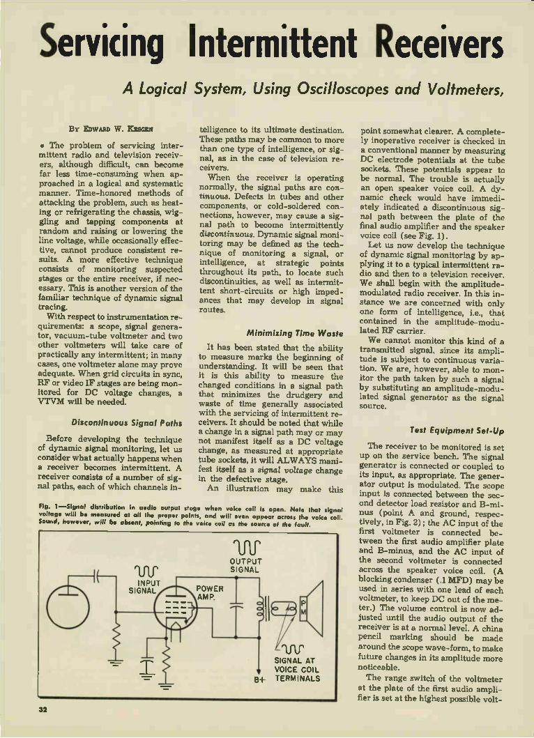
Servicing Intermittent Receivers A Logical System, Using Oscilloscopes and Voltmeters,
BY EDWARD W . K.ESGEN
• The problem of servicing inter-mittent radio and television receiv-ers, although difficult, can become far less time-consuming when ap-proached in a logical and systematic manner. Time-honored methods of attacking the problem, such as heat-ing or refrigerating the chassis, wig-gling and tapping components at random and raising or lowering the line voltage, while occasionally effec-tive, cannot produce consistent re-sults. A more effective technique consists of monitoring suspected stages or the entire receiver, if nec-essary. This is another version of the familiar technique of dynamic signal tracing. With respect to instrumentation re-
quirements: a scope, signal genera-tor, vacuum-tube voltmeter and two other voltmeters will take care of practically any intermittent; in many cases, one voltmeter alone may prove adequate. When grid circuits in sync, RF or video IF stages are being mon-itored for DC voltage changes, a VTVM will be needed.
Discontinuous Signal Paths
Before developing the technique of dynamic signal monitoring, let us consider what actually happens when a receiver becomes intermittent. A receiver consists of a number of sig-nal paths, each of which channels in-
telligence to its ultimate destination. These paths may be common to more than one type of intelligence, or sig-nal, as in the case of television re-ceivers. When the receiver is operating
normally, the signal paths are con-tinuous. Defects in tubes and other components, or cold-soldered con-nections, however, may cause a sig-nal path to become intermittently discontinuous. Dynamic signal moni-toring may be defined as the tech-nique of monitoring a signal, or intelligence, at strategic points throughout its path, to locate such discontinuities, as well as intermit-tent short-circuits or high imped-ances that may develop in signal routes.
Minimizing Time Waste
It has been stated that the ability to measure marks the beginning of understanding. It will be seen that it is this ability to measure the changed conditions in a signal path that minimizes the drudgery and waste of time generally associated with the servicing of intermittent re-ceivers. It should be noted that while a change in a signal path may or may not manifest itself as a DC voltage change, as measured at appropriate tube sockets, it will ALWAYS mani-fest itself as a signal voltage change in the defective stage. An illustration may make this
Fig. 1—Signal distribution in audio output stage when voice coil is open. Note that signal voltage will be measured at all the proper points, and will even appear across the voice coil. Sound, however, will be absent, pointing to the voice coil as the source of the fault.
point somewhat clearer. A complete-ly inoperative receiver is checked in a conventional manner by measuring DC electrode potentials at the tube sockets. These potentials appear to be normal. The trouble is actually an open speaker voice coil. A dy-namic check would have immedi-ately indicated a discontinuous sig-nal path between the plate of the final audio amplifier and the speaker voice coil (see Fig. 1). Let us now develop the technique
of dynamic signal monitoring by ap-plying it to a typical intermittent ra-dio and then to a television receiver. We shall begin with the amplitude-modulated radio receiver. In this in-stance we are concerned with only one form of intelligence, i.e., that contained in the amplitude-modu-lated RF carrier. We cannot monitor this kind of a
transmitted signal, since its ampli-tude is subject to continuous varia-tion. We are, however, able to mon-itor the path taken by such a signal by substituting an amplitude-modu-lated signal generator as the signal source.
Test Equipment Set-Up
The receiver to be monitored is set up on the service bench. The signal generator is connected or coupled to its input, as appropriate. The gener-ator output is modulated. The scope input is connected between the sec-ond detector load resistor and B-mi-nus (point A and ground, respec-tively, in Fig. 2) ; the AC input of the first voltmeter is connected be-tween the first audio amplifier plate and B-minus, and the AC input of the second voltmeter is connected across the speaker voice coil. (A blocking condenser (.1 MFD) may be used in series with one lead of each voltmeter, to keep DC out of the me-ter.) The volume control is now ad-justed until the audio output of the receiver is at a normal level. A china pencil marking should be made around the scope wave-form, to make future changes in its amplitude more noticeable. The range switch of the voltmeter
at the plate of the first audio ampli-fier is set at the highest possible volt-
32

by Dynamic Signal Monitoring for Dealing with the Most Difficult of Repair Problems.
age range, to minimize the meter's loading effect on the circuit. The same precaution is recommended whenever a meter with a relatively low input impedance (1,000 ohms-per-volt) is connected across a high-impedance circuit. Once monitoring has been started,
the receiver requires no further at-
Fig. 2—Initial monitor points
these signal-tracing tests have been concluded, as so often happens, mon-itoring is resumed, but at different points. Taking the last case as an example,
we know that there is no signal dis-continuity up to the first amplifier plate. Following the basic procedure previously outlined, we might now
monitoring setup for intermittent AC-DC broadcast are: A and ground; B and ground; C and ground.
tention until a change of audio level is noted. It is suggested that the technician attend to other duties, keeping within earshot of the re-ceiver, however, as monitoring pro-gresses. When a change of audio level is
noted, a check of the instruments will indicate the vicinity of the trouble. If, for example, all readings show a substantial reduction, we may conclude that the trouble lies either ahead of the second detector load resistor, or possibly in the power supply. If, on the other hand, the voltages across the demodulator load resistor, and between the first audio plate to ground, remain sub-stantially unchanged, but a pro-nounced decrease is noted across the voice coil, we know that a source of signal discontinuity exists between the first audio plate and the voice coil.
In either case, the area to be in-vestigated has been narrowed down considerably. Dynamic signal tracing (not monitoring) may now be advan-tageously employed to pin-point the source of the trouble. If the receiver begins to function normally before
radio receiver. Suggested
connect our scope between grid and ground of the audio output tube, a voltmeter between plate and ground of the audio output tube, and another voltmeter across the voice coil.
It should be noted that monitoring is merely a watch-and-wait proce-dure. When the monitor instruments indicate that the intermittent is in its
active phase, monitoring is aban-doned, and signal tracing via a signal generator and scope or voltmeter is resorted to. When the set operation becomes normal, signal tracing is abandoned, and monitoring is re-sumed. While the time consumed during
monitoring may be considerable, this does not represent wasted manpower, as other work is being done while the receiver is being monitored. The time actually spent on trouble shooting is negligible when compared to other less systematic methods. Results are also positive—i.e., definite—when dynamic signal monitoring tech-niques are employed.
Monitoring CRT Socket
Let's now consider a common tele-vision receiver complaint. An inter-mittent TV receiver may operate normally for a long period of time, then the screen will suddenly go dark. Audio output remains unaf-fected; this would indicate that the low-voltage power supply is prob-ably functioning normally. The CRT socket would appear to
be a likely place to begin monitoring. The common leads from all the volt-meters are connected to the cathode of the CRT; the positive DC voltage leads are connected to points A, B and C respectively (see Fig. 3). A
(Continued on page 45)
Fig. 3—Initial monitoring setup for TV receiver with intermittent raster. Part of an RCA 630TS circuit is shown. Suggested monitor points are: A and ground; B and ground; C and ground.
33

The ABC of Transistors What the Technician Should Know About These New Devices.
• The idea of controlling the flow of electrons in a particle of solid material is almost as old as the ra-dio art itself. In the early part of this century the galena crystal de-tector was the most popular means of detecting radio signals. This crys-tal detector consisted of a small chunk of galena (a lead ore), mounted in a lead cup with one ir-regular surface exposed. A "cat-whisker" wire was used to probe the exposed galena surface for the
EMITTER
METAL SUPPORT
GLASS STEM
PLASTIC CASE
COLLECTOR
GERMANIUM CRYSTAL
BASE CONNECTION
Fig. 1—Enlarged point contact tran-sistor. The base connection is made to a large-surface crystal area. The emitter and collector wires touch the other large-surface area.
most sensitive spot, the one which produced greatest audio response The terminals of this crystal detec-tor were the lead cup and the cat-whisker wire. The modern equiva-lent of this arrangement is the ger-manium crystal diode detector unit; the 1N34 is a well-known example. With the development of vacuum
tubes in the second decade of this
N TYPE GERMANIUM CRYSTAL 'Yes
•
century, researchers turned their attention to these new electronic tools. New circuits, particularly in radar and other high-frequency ap-plications, have pointed up the shortcomings of vacuum tubes in modern electronic equipment. Ex-perimenters, now equipped with a good knowledge of electron behav-ior in vacuums, have turned again to solid materials to help them to solve problems in modern electronic circuit design. One of the results of current research into the properties of solids as semi-conductors is the transistor. The first transistor (developed by
Bell Telephone Laboratories in 1948) had two cat-whiskers touching the crystal instead of the old single-wire probe. By the addition of a second cat-whisker wire and the use of a different material (germa-nium), the old crystal detector was made into an amplifier. Germanium compounds have lent
themselves, with relative ease, to modern manufacturing processes which can be controlled to produce desired electronic properties. The structure of the germanium crystal can be altered by these processes so that a wafer of the crystal may be-come an N-type or P-type unit. The N-type germanium has an atomic structure which produces a surplus of electrons ready to form a cur-rent; it is called N-type because it resembles the negative pole of a battery—the pole with an electron surplus. The P-type germanium has
Fig. 2—Enlarged point-contact transistor: If a signal injects 1 million holes at emitter, they will be attracted towards collector M. Near collector, holes reduce barrier to electron flow 121 allowing some 2.5 million electrons to pass into crystal. Of these, 1 million neutralize the holes ;the others flow to base In
34
an atomic structure which leaves vacancies or holes for electrons. These holes act like positive charges in that they attract electrons from adjacent atoms; thus, there is the effect of the holes moving through the germanium during current flow. The holes move in an opposite di-rection to that of the electrons.
All transistors may be said to fall into one of two groups: point-con-tact transistors and junction tran-sistors. Within each of these groups there are different types with dif-ferent operational characteristics. The point-contact transistor will be considered first. A transistor of the point-contact
Fig. 3-50 MC oscillator circuit using a point-contact transistor.
group contains a germanium pellet, usually of N-type material, with three electrical contacts made to it. The largest contact is called the base contact; this contact touches the pellet along its large surface (see Fig. 1). The other two contacts are made to the surface opposite the base contact area; they are composed of cat-whisker wires whose points just touch the germanium and are spaced about 1/500-in. apart. One of these wires is called the emitter, the other is" called the col-lector. The three contacts are firmly positioned and the unit is sealed in a plastic.
In the most elementary point-contact transistor amplifier circuit, the emitter and base connections are made to a DC source in series with the input signal (Fig. 2). The DC minus terminal is connected to the transistor base terminal; the DC plus goes through the signal source, to the emitter terminal. The emitter appears to produce holes in the germanium at the wire contact point. These holes act like positive charges and drift across the small distance to the collector, attracted by the negative voltage (electron

for TV and Radio Their Incorporation into Compact Chassis Is Not Far Away.
surplus) on the collector. The col-lector and base are connected to a second DC source in series with the output circuit. The plus terminal of this second DC voltage source is connected to the transistor base con-nection; the DC minus goes through the output circuit to the collector. The hole drift to the collector low-ers the resistance of the germanium
(b)
EMIT TER
INPUT
BASE
COLLECTOR • OUTPUT
92CM-796.13
Fig. 4—Three circuits showing how point-contact or junction transistors may be connected for use as ampli-fiers.
around the collector contact point, and a heavy electron flow in the col-lector circuit results (see Fig. 2). The collector circuit corresponds
to the output, and the emitter cir-cuit to the input, of a conventional vacuum-tube amplifier. The current flow in the collector circuit is greater than the flow in the emitter circuit; the difference between the currents represents the gain of the transistor amplifier. Point-contact transistors are able to produce from 2 to 2.5 times the emitter circuit current in the collector circuit. Power gain, however, is greater than this because the collector cir-cuit resistance is much higher than the resistance of the emitter cir-cuit, and the work done in this circuit (PR) is correspondingly
higher. In practice, point-contact resistors can boost the power of a signal about 20 DB, which repre-sents a signal power gain of 100. Because some of the collector cir-
cuit current from the base connec-tion flows to the emitter wire, cur-rent feedback exists in the tran-sistor. Point-contact transistors, therefore, are used as oscillators; oscillator frequencies above 300 MC have already been attained, and this ceiling is being pushed higher in laboratory experiments. The sche-matic of a transistor oscillator cir-cuit for operation in the 50 MC re-gion is shown in Fig. 3.
In the conventional vacuum-tube amplifier, the cathode is at ground signal potential or "cold," the con-trol grid is at input signal potential or "warm," and the plate is the "hot" electrode at which the ampli-fied output signal appears. These relative designations ("warm," "hot" and "cold") are different in a grounded-grid amplifier and again in a cathode follower circuit. All three circuit arrangements are pos-sible with transistors (see Fig. 4). The phase relationships between
input and output signals which ex-ist in grounded-cathode, grounded-grid and grounded-plate vacuum-tube stages have their counterparts in transistor circuits. The following
BASE CONNECTION
1
Hoes if
EMITTER
phase relationships between input and output signals will be present in such circuits: Transistor base con-nection grounded—signals are in phase; Transistor emitter grounded —signals are 180 degrees out of phase; Transistor collector grounded —signals are in phase. Point-contact transistors have
their main applications in high-fre-quency circuits such as FM and television RF amplifiers, oscillators and IF amplifiers; they are particu-larly useful for high-speed switch-ing and pulse circuits in electronic computers. Junction transistors are made by
constructing a tiny sandwich of three layers of germanium. The sandwich is arranged with a section of N-type, a section of P-type and a section of N-type germanium; this is called an N-P-N junction tran-sistor. The P-N-P transistor has its sandwich made of sections of P-type enclosing the single N-type germanium layer. For both N-P-N and P-N-P transistors, three con-necting wires are brought out, one . from each section. The complete germanium sandwich with connect-ing wires is sealed in an opaque plastic casing. This unit is then en-closed in a slightly larger plastic container with the leads protruding
(Continued on page 46)
O
Fig. 5—Enlarged junction transistor. Small signal from phonograph, amplified to activate loudspeaker is assumed. If the signal changes by 1 million electrons, there will be a voltage difference between emitter and base which starts 50 million holes flowing out of emitter Ill. All but 1 million holes get to collector, inducing 49 million electrons to flow and carry current in collector circuit (2). The remaining holes flow to the base completing base-emitter circuit (3). (This
and other sketches, courtesy RCA.)
35

Servicing Phono Motors and Wow, Rumble, and Scraping Problems in Single-Speed
By HARRY M ILEAP
• Of the many elements that go to make up a home music system, this article will confine it-self to only one: the record player. The record player is primarily a
mechanical device. It is more impor-tant to prevent the introduction of noise and distortion at the record player than in any other part of the overall audio system. This is so be-cause distortion or noise developed at the player passes through the en-tire system and is greatly amplified; more so than the distortion or noise that is developed at any other point in the audio system. The chief trou-bles that develop at the player are wow, rumble, and scraping. The basic parts of the record
player are: 1—The motor. 2—The drive assembly. 3—The turntable. 4—The pickup arm and cartridge. The last-named units will be dis-cussed in another article. The Motor. Noise and distortion
can be developed by the motor in many ways. If the armature (see Fig. 1) is not seated properly in a verti-cal position, it will rub against the field poles. If it is only slightly off the vertical plane, it may merely cause a scraping sound to be audi-ble. If the armature is too far off, however, and there is too much pressure applied to it by the field poles, the speed of the armature will decrease, possibly causing wow; or the armature may not turn at all.
Ordinarily, this condition is brought about when the screws holding the bearing bracket have worked loose. The trouble can easily be remedied by shifting the position of the bear-ing bracket (while rotating the ar-mature) until the armature rotates freely. Hold the bearing bracket in this position and tighten the bracket screws, to complete the repair.
If the bearing portion of the bear-ing bracket wears too much, the ar-mature will tend to vibrate from side to side, introducing excessive noise. A worn bearing can easily be located by inspection. The only remedy for the condition is replace-ment of the bearing bracket.
Armature Vibration
Armature vibration can also oc-cur in the vertical direction. This condition is brought about by worn, bent or broken washers (see Fig. 1). The purpose of the washers is to hold the armature firmly in position and prevent it from bobbing up and down. If any of these washers are bent, broken, or missing, the arma-ture will tend to vibrate and cause noise. The washers referred to usu-ally snap into grooves that are cut around the armature shaft. On some motors, the armature is held in place by the front and rear of the armature itself; there are usually a number of "shim" washers between the armature and the bearing bracket, to hold the armature in po-sition as firmly as possible
Fig. 1—Shaded 4-pole squirrel-cage phonograph motor. If this assembly is not properly seated in the vertical direction, correct turntable speed will not be obtainable.
Phono motors require lubrication periodically, not only to prevent un-necessary wear on the armature and bearings, but to keep the armature as free-running as possible. If there is a lack of lubrication at the bearings, the armature shaft will tend to bind. The extra pressure exerted due to the lack of lubrication tends to slow down the motor and may cause wow. A light grease should be used for lu-bricating purposes; oil splatters and is easily lost. A heavy grease tends to slow down the motor, and should not be used for this reason. The phono motor may develop a
high resistance in its windings, or a low magnetic field, causing it to slow down. The only remedy for such a condition is to replace the motor. Use only a direct factory re-placement. This is necessary be-cause the diameter of the motor drive shaft helps determine the speed of rotation of the turntable.
The Drive Assembly. The drive assembly is generally the most troublesome section of the record player. The purpose of the drive as-sembly is to couple the motor drive shaft to the turntable, and keep the turntable rotating at a proper, con-stant speed. Never apply oil or grease to the drive assembly. This unit depends on friction for its proper operation; the application of a lubricant will cause slipping, and may result in the turntable not ro-tating at all. Fig. 2 illustrates a basic one-speed drive assembly. The drive wheel has a rubber tire
that is the coupling surface between the motor drive shaft and the rim of the turntable. This rubber tire develops various defects that affect the operation of the record player. In its normal condition, the tire pro-vides friction and is perfectly round. If either one of these characteristics changes, noise, or wow due to slip-ping, may result. The rubber tire is so constructed
that it provides good traction at the rim of the turntable. If the outer edge of the rubber tire becomes ex-cessively smooth, it will slip and cause the turntable to rotate at a slower speed, or possibly not at all. After the rubber tire is in use for a while, it may wear irregularly and develop flats or indentations (see Fig. 3A). This condition will cause a
36

Drive Assemblies and Three-Speed Record Players.
thump or rumble whenever the tire comes in contact with the motor drive shaft and the turntable. Fig. 3B shows how the rubber tire may be removed from the drive wheel.
If the drive wheel binds on the drive wheel shaft, it will cause the turntable to rotate slowly or not at all. Lubricating the drive wheel shaft will ordinarily prevent this. Care must be taken, when applying the lubricant, to prevent the latter from coming in contact with the drive wheel rubber surface.
Slipping may also be caused by a weak drive wheel spring. The pur-pose of the spring is to pull the drive wheel tightly against the turntable rim. A weak spring will cause the drive wheel to slip, re-sulting in the turntable rotating slowly or not at all. The purpose of the cotter pin is
to prevent the drive wheel from rising. If the cotter pin is missing, the drive wheel will be pushed up, causing it to rub against the under-side of the turntable. A 3-speed record player system
is shown in Fig. 4. The basic differ-ence between a 3-speed and 1-speed player lies in the use of three idler wheels in the 3-speed unit (one for each speed). When the control arm is moved to the speed position desired, the idler wheel for that speed is moved be-tween the motor drive shaft and the drive wheel. The three-speed rec-ord player is subject to the same troubles as the single-speed unit. The lower section of the idler wheels are rubber-rimmed, and de-velop the same defects drive wheels do.
The Turntable. The turntable has definite requirements to fulfill, to provide adequate operation. It must be flat, parallel to the mounting board and able to rotate freely; it should also grip the record being played.
If the turntable is warped, the rec-ord being played will wobble, caus-ing the pickup needle to skip and jump grooves.
If the turntable is not parallel to the mounting board, it will prob-ably come in contact with the mount-ing board, resulting in scraping. This turntable scraping is usually the result of the spindle not being prop-
erly seated in a vertical position. A simple bend-adjustment can easily remedy the condition. The turntable center-hole can
become enlarged due to wear, caus-
ing the turntable to rest too loosely on its support; the turntable will tend to slant and scrape the mount-ing board in consequence. If the spindle wears excessively, a similar condition will be produced. In some cases, the turntable may
show a tendency to bind on the spindle, causing it to slow down or jam. Applying grease to the bearing portion of the spindle will solve the problem in most instances. If it does not, the spindle or the center-hole
(Continued on page 46)
Fig. 2—Single-speed drive assembly. The drive wheel makes contact with the turntable rim.
Fig. 3A—Flat and identaHon on drive-wheel tire. 8—Removing tire from drive wheel.
Fig. 4—Three-speed drive assembly showing separate idlers mounted on selector lever.
37

Servicing Printed Chassis Recommended Soldering Technique for "Etched-Metal" Radios
BY JACK BAYHA
CHIEF ENGINEER, PHEN-O-TRON, INC., NEW ROCHELLE, N. Y.
• The rash of etched-metal radio sets appearing on the market, and the millions to come soon, have placed many servicemen in some-what of a dilemma. Actually a bless-ing in disguise, the printed chassis seems like a Frankenstein monster to many technicians. Some of them, in fact, are even refusing to service sets of this type. The etched-metal, or as some call
it, printed-circuit radio, is actually easier to service than a conventional set, once you know the tricks of the trade, and can put them into prac-tice. There is no great secret to suc-cessful etched-metal service work. Follow the simple methods outlined here, and you will find servicing a pleasure.
Photo of unsoldering lob in progress on a late-model Admiral printed-chassis radio.
Several types of etched-metal, embossed-circuit and printed-circuit sets exist. In the true printed-circuit receiver, the wiring is electroplated on a layer of conductive (metallized) ink, printed on a sheet of phenolic plastic material, and deposited by a printing or silk-screening process. The bond between the chassis and wiring is very delicate, and special care is therefore necessary during servicing. The embossed circuit is made by
stamping metal or metallic powder into the surface of the plastic; the bond to the base material is quite strong. The most popular form, the
etched-metal panel, is made by etch-ing away from a solid sheet of cop-per, which is bonded to the plastic, those areas where wiring is not wanted, leaving solid copper wiring. Bond strength is excellent. The following tools and accessories
are needed to service any of the three receiver types just mentioned:
1. A good pair of long-nose pliers. 2. 60-40 low-temperature solder
with rosin core. 3. A glue brush (app. cost, five
cents) purchasable at the local hard-ware store.
4. A 25-watt soldering iron. A higher-wattage will not do.
5. Tinned wire, such as resistor or capacitor pigtail clippings.
6. Carbon tetrachloride.
Solder Removal
As you probably know, etched-metal sets are assembled by either automatic or dip soldering in a mat-ter of seconds; getting them apart, however, is not as speedily achieved, as you may well have found out. Maybe you are one of the service-men who have turned the air blue in your immediate area with words not meant for tender ears, as you smashed tubes and speaker, and broke chassis boards, trying to ex-tract a particularly stubborn i-f can from the death grip in which the chassis held it. The answer to the problem lies in getting the solder away from the joint between the etched conductor and the com-ponent. Removing the solder from a joint
is readily accomplished with the glue brush and the low-wattage iron. Heat the joint cautiously; if the set manufacturer has bent the prongs of some unit in forty directions, as sometimes happens, straighten them with your long-nose pliers. By heat-ing the joint again and rapidly brushing it, you can brush off the still molten solder. Since the solder present in the set has a very low melting point, and a low-wattage soldering iron is being used, the conductor will not generally be lifted from the base plate during this op-eration.
Component Installation
After eliminating all the solder by brushing, remove the component carefully, using your iron to smooth out the solder left on the pattern. Be sure to leave the component holes open for insertion of a replacement. Clean the chassis area around the repair zone with carbon tetrachlo-ride, before installing the replace-ment part.
Install the new component with care, so as to not lift the pattern; then solder it in place with the special low-temperature solder. Leave coating of rosin in place, to act as a protective layer.
Successful removal and replace-ment of a component without dam-age to the conductors is not always possible, and occasionally a conduc-tor section will break off. Repairs are readily made in such a case by soldering a short piece of tinned wire to the damaged conductor. Re-sistor or condenser pigtails are ideal for this purpose. At all times use only a low-wat-
tage soldering iron, always brush all joints free from solder, use only 60-40 solder, and be just a little careful—and etched-metal radio servicing will be a cinch. You will soon find the excellent accessibility, and absence of conventional wires, more than makes up for the extra care needed to service these sets. By all means learn to service
these units—you'll be getting plenty of this type of work soon, as almost every major manufacturer is cur-rently putting such sets on the mar-ket, or will do so in the near future.
38

Servicing AC-DC Radios Part 1 Hard-To-Find Troubles.
BY M. G. GOLDBERG
• With the advent of television, many technicians have treated radio as though it belonged in a museum along with the hand-wound phono-graph. Millions of radios, however, still lind their way each year to service shops. Most radios sold and serviced to-
day are of the AC-DC type, using 4, 5, or even 6 tubes. Probably 75c,,' or more of all troubles on AC-DC receiv-ers are caused by either shorted or burned-out tubes, with other less frequent complaints due to dried-out
-mILLIAMmE TER
NOtE REDUCED $23•7 FILAMENT VOLTAGE TUE SMALL INCREASE IN CURRENT IS INSUFFICIENT TO MAKE UP FOR 30% DECREASE IN THE 1OSA? NEATER RESISTANCE
Fig. 1 A—Normal heater voltage readings. B—Readings with defective 12SA7 in set.
filter capacitors, rubbing speaker cones and torn or slipping dial drive cords. All of these troubles have quite obvious symptoms and their cures are almost all self-evident. A small percentage of sets, however, turn out to be brain teasers and gray-hair inducers; these are the sets to which we shall direct our attention in this article, as well as in the ones to follow. Let us consider, for a start, the case
of a standard-brand 5-tube AC-DC set which comes into the shop for repair, with the complaint that the set either cuts out after playing a while, or
Fig. 2—Above-normal current flows in de-fective 12SA7 heater, due to its connection across the 12.6v supply of the tube-checker.
LINE INPUT
slILLIANNETER
doesn't start working at all. When the set quits working, the pilot light re-mains on, ruling out the possibility of an open tube heater. All tubes check good on the tester. Although the set sounds "alive", no station is received.
Test Results
A quick pass with the signal generator output lead (generator set at 455 KC, 400-cycle modulated signal used) shows plenty of output in the speaker; the IF trimmers peak nor-mally, indicating that the trouble originates in the oscillator-mixer cir-cuit. Oscillator and mixer plate volt-ages are near normal, but no negative voltage is present at the oscillator grid. The signal generator is next tuned
to 1955 KC and its output lead clipped to the oscillator grid terminal. A strong local station comes in fine at 1500 KC, proving that something in the oscillator circuit is wrong. The 12SA7 is rechecked, and still tests good; we try another tube in the set anyway, and everything works fine and stays that way. To find out why the old tube didn't work, we put it back in the set and check all heater voltages. Nine volts appear across the 12SA7 filament terminals, and nor-mal or slightly above normal volt-ages are measured on the other heaters.
Wattage Too Low
A resistance check on the 12SA7 filament shows it to be below normal, with the heater partially shorted out. Since the current thru the tube is limited to slightly more than 150 ma by the presence of the other tube filaments in the series-string, the wattage (E x I) consumed by the heater is only 9 x .15 or 1.35 watts, compared with the 12.6 x .15 or 1.89 watts that is normally present. When the defective tube is placed
in the tube checker, the transformer winding of the latter is in parallel with the heater, and delivers 12.6 volts to its terminals. Since the re-sistance of the tube has dropped to approx. 60 ohms from 84 ohms nor-mal, the current it draws in the tester is 210 ma, producing a power con-sumption of 2.6 watts—more than enough for proper cathode emission (see Figs. 1, 2). A "fooler," eh?
When a hard-to-find trouble is present in an old midget set that needs a new tube, electrolytic, etc., the profit margin moves toward the vanishing point. One of the ways to economize on such an old "dog" set, when a filter replacement is re-quired, is indicated in fig. 3.
If the hum level of the receiver is unusually high, and shunting a new filter of, say, 30 mfd across C-1 and C-2 in turn has little effect in reduc-ing the hum, turn off the set and re-sistance-check the filter resistor R-1 (see Fig. 3). Often this resistor has been overheated and its resistance is below normal, reducing its filtering effect. Or the "hot" leads of the ca-pacitor may have shorted together internally, effectively reducing the pi-section filter to a single capacitor. Both troubles can be checked for
by measuring the voltage drop across R-1 when the set is operating. If the drop is very low, it indicates that either one or the other fault men-tioned is present, and must be cor-rected. Resistance and condenser substitution checks (with the original filter capacitor disconnected) will readily localize the trouble.
Fig. 3—Tying "hot" leads of reduced-value dual filter together makes it possible to add only a single capacitor (C-3) as replacement.
Part 2 Alignment Pointers
• Technicians making home service calls are often called upon to check a small receiver in the home, per-haps one that the man of the house
39

Servicing AC-DC Radios (Continued)
has messed up by turning all the i-f and tuning gang trimmer screws. Since few technicians carry signal generators around in their cars, the following hints regarding the pro-cedure necessary to quickly bring the set back to reasonably accurate alignment and sensitivity may be helpful.
First, set the dial pointer on the dial cord so that it travels to the proper end points when the tuning condenser is 1—in full mesh and 2—wide open. If there is any doubt as to just where the extreme points of travel on the slide plate are, ex-amine the front and rear of the plate. In traveling back and forth during tuning, the pointer will have left a path of gummy deposit on the slide plate, and a tiny mound of dirt at each end of its travel. The pointer can be clamped to the cord at such a point that it travels the same path. Before doing this, clean the slide-plate surface with carbon tet. Now tune in some station between
1450 and 1600 kc on the dial. If the set is so far out of alignment that no station can be received, clip a 5-ft. length of wire to the stator lug on the tuning gang mixer sec-tion. This will provide sufficient pickup to permit the necessary adjustments.
If a station that should appear at 1500 kc is picked up at, say, 1570 kc, adjust the oscillator trimmer until it comes in at the correct point on the dial; then peak the i-f's by ear. If the i-f is to be adjusted to 455 kc, the image of 1500 kc should be heard at 1500 minus (2 x 455), or 590 kc, when the alignment is correct. If, however, the station comes in at 560 kc, instead of at 590 kc, it indicates that the i-f trimmers are set to (1500-560) /2 or 470 kc. Turn the screws outward 1/8th turn in such a case, and adjust the
Fig. 1A—The normal relationship of the r-f frequency. B—Why images of stations below
(A)
(B)
570 KC WNAX CARRIER; KSTP IMAGE
iii i 580 KSTP IMAGE 0500-(2 9460U
465 KC IF
T 465 KC 1 1035 KC
OSCILLATOR OPERATES AT THIS FREQUENCY TO RECEIVE 570 KC CARRIER
570 KC WNAX CARRIER
460 KC IF
1500 KC KSTP CARRIER
t 47"C el
1030 KC NEW OSCILLATOR FREQUENCY FOR 570 KC CARRIER
1500 KC KSTP CARIHER
Fig. 2A—How the image of a 1500 kc transmission heterodynes with a 570 kc station to create beat interference. B—How shift to a new i-f eliminates image of undesired station.
oscillator so that the station again comes in at 1500 kc. Re-peak the i-f trimmers for maximum and check the image again. If it is still off a bit, repeat the above procedure until the image is received correctly at 590 kc. We can now remove the extra length of wire and adjust the mixer section trimmer for maximum audible output from the speaker.
If the receiver has a tuned r-f stage and uses a 3-gang condenser, the attenuation of the image signal is apt to be so great that the latter is not audible, unless the receiver is very close to the transmitting an-tenna, and direct pickup occurs through the oscillator or mixer wir-ing. Connecting the short wire to the mixer section temporarily by-passes the r-f stage, preventing such image signal attenuation. For a final adjustment, tune in a
very weak station between 1400 and 1600 kc and peak all trimmers, or tune off station between these settings and peak for maximum noise output. The advantage of the latter procedure is that the avc (automatic volume control) circuit in the receiver is inoperative, and the ear can recognize small changes
carrier, oscillator frequency and the image 1450 kc (app.) cannot usually be received.
(A1
(9)
DIAL SCALE
55
- - 455 KC - - - -19- - - - - 455 KC - - - -It --- 455 KC - - - -01
IMAGE OF 1500 KC • 590 Kr
1. _110._ .120....130. 140 150... .160. .
WHEN DIAL POINTER IS AT 590 KC, AND THE IMAGE OF 1500 KC IS AUD1BLE,THE OSCILLATOR IS OPERATING AT 1045 KC.
455 KC - - - - - 455 KC
60. 70....60.... 90
IMAGE OF 1400 KC IS
OFF SCALE AT 49 KC.
LWHEN SET IS TUNED TO 1500 KC,OSC.FREQUENCY IS NORMALLY 1500+ 455. 1955 KC.
100....110....120....130. 140 ...ISO._ .160._
455KC -1101
.CO. _MO-
OSC WORKS AT 945 KC TO PRODUCE AN IMAGE OF 1400 KC
WHEN RECEIVING 1400 KC NORMALLY, OSC FREQUENCY IS 1400 +455.1955 KC
in noise intensity more readily. The reason for choosing a station in the tuning range between 1450 and 1600 kc is that the image of a station lower than 1450 kc (app.) will fall beyond the range of the dial scale (see Fig. 1 A, B). Images of strong local stations be-
tween 1600 kc and 1400 kc can give rise to objectionable beat inter-ference on 2-gang receivers, when the set is tuned to receive a weak or distant station between the low-frequency end of the dial and 600 kc (see Fig. 2A). Many farmers beyond the limits of the city in which the writer lives tune in on WNAX, which comes in from about 250 miles away on 570 kc. Some of the receivers are older types with i-f's at 460 to 470 kc. If the i-f's happen to be set to approximately 465 kc, the image of KSTP, a strong local on 1500 kc, will be heard along with WNAX, spoiling the reception of the latter. The oscillator in this case beats
with the frequencies of both stations to produce the same i-f. If the trim-mers are repeaked 5 kc either lower or higher than 465 kc, the image of KSTP will move 10 kc away from 570 and the interference will dis-appear (see Fig. 2B). If the new i-f is chosen as 460, the oscillator will work at 1030 to receive WNAX at 570, and the image of KSTP at 1500 will be 580 kc—too far away to be tuned in at 570 kc. This remedy can be applied in
other localities around the country, where the same problem exists. To eliminate the possibility of
damage to both test equipment and receiver, always use an isolation transformer between the ac line and the ac-dc receiver being serviced. Since most of these sets consume only about 30 watts, any standard transformer will be satisfactory.
40
1 170. 1130... 190..

Part 3. Odd Fading Case. Locating Intermittent Filaments Quickly
BY M. G. GOLDBERG
• An intermittent in any receiver is somewhat of a headache, but a periodic fading or cut-out in an ac-dc receiver is even worse, be-cause these receivers cost the cus-tomer comparatively little; service charges must therefore be kept low, and any job which consumes a lot of bench time means money lost. Let's consider a case in point. The output of this 5-tube set
dropped just enough to be annoying several times during a program, cutting in and out with a volume change of 15 or 20%. After trying all new tubes and making other tests, the trouble was finally nar-rowed down to the second i-f and detector circuits illustrated in Fig. 1. During the fading period, the fre-
quency of the received station re-
Fig. 1-14 and second-detector circuit of 5-tube ac-dc receiver. Intermittent open-circuiting of condenser "X" resulted in fading.
mained constant (the oscillator didn't shift) ; the tone was not ap-preciably affected, and there was no click when the set cut in and out. Connecting the scope input cable to points A, B, and C in turn showed no change in response during the fading; with the scope connected from point D to chassis ground, however, the set did not cut out. The connection just cited was made several times, with the same result. The writer finally concluded that
the small capacitor marked "X" in Fig. 1 (a 50 mmfd unit) was opening and closing periodically. With the scope disconnected and the capaci-tor open, the i-f signal was not sufficiently bypassed, causing the audio output to drop. With the scope connected, however, the 75 minfd capacitance of the latter's input cable was more than sufficient to substitute for capacitor "X" in the circuit, and no fading was therefore noticeable.
Intermittent heaters in ac-dc re-ceivers are often troublesome. An
undue amount of time may be wasted in determining which tube in the series string is opening up. This applies especially to receivers in which the trouble occurs only spasmodically, and then for only a few seconds at a time. Naturally, the technician can't spend an hour or two on one of these low-priced sets, waiting around for a heater to open. The writer has worked out a simple and speedy system for lo-cating the defective tube in such cases, without spending more than a few minutes of bench time on the job.
Let's refer to Fig. 2A. Here we have a conventional 5-tube heater string in which an intermitent fila-ment is present—one which won't stay open long enough for a routine check, and which cuts out perhaps only three or four times during an hour's program. Note the two ac voltmeter connections. One meter (VM-1) is attached across the two higher voltage heaters; the other connects across the three lower voltage filaments. Place the meters where they can
be readily seen dnd turn the set on then go to work on another bench job. As long as the continuity of the heater circuit is intact, VM-1 will read approximately 85 volts; VM-2 will read about 35 volts. When the cutout occurs, attracting the serv-iceman's attention, a glance at the meters will reveal that one meter is now indicating practically full line voltage, while the other has dropped to zero. Assume that VM-1 has gone to
zero and VM-2 to full line voltage, on the first fade. This means that the intermittent is in one of the 12-volt heaters. Now connect the me-ters as shown in Fig. 2B. If, on the next fade, both meters go to zero, it will prove that the 12SA7 is the bad tube. On the other hand, if one of the meters goes to zero, while the other reads full line voltage, the defective tube will be the one across which full line voltage is measured. This simple arrangement checks all five tubes in only two fades, and almost makes child's play out of what could be a time-consuming headache.
If, on the first fade, VM-1 goes to full line voltage (Fig. 2A) while the VM-2 reading drops to zero, con-nect one meter across each of the two higher voltage heaters for the 2nd test.
Fig. 2A—Connection of 2 ac voltmeters across tube filaments for first fading check. B—Volt-meter connections for the second fading check.
Color-TV System (Continued from page 5)
ever, available. The ingenious solu-tion to this problem worked out by engineers was to shift the phase of the carrier 90 degrees, effectively creating another carrier. One carrier signal is modulated by the blue sig-nal, while the second is modulated by the red one.
If a vectorial representation was made of the situation, two vectors at an angle of 90 degrees would be drawn, one for each of the sub-car-riers. The phase angle of the result-ant vector would represent the hue information; the amplitude of the re-sultant would stand for the satura-tion intelligence. The output of the blue and red
balanced modulators are combined with the luminance and sync signals to make up the composite trans-mitted signal. The reader will note (Fig. 3) that
the sync generator has a color-burst generator circuit associated with it. The circuit permits a sample of the subcarrier outout to be transmitted along with the horizontal sync infor-mation. This subcarrier signal sample is transmitted (along with the hori-zontal sync information) as a short 8-cycle, 3.58 MC signal burst (see Fig. 4). The burst occurs during the time interval occupied by the back porch of the horizontal sync pulse. The receiver uses this color sync in-formation to keep a color oscillator operating at the correct phase and frequency, in a manner somewhat similar to the automatic frequency control of horizontal deflection cir-cuits. The color oscillator signal is ap-
plied to the receiver's red and blue color demodulators, along with the chrominance signals. The blue and red color information is recovered at the output of the color demodulator (just as black and white video sig-nals are extracted from the video IF information in the video detector).
41

What's Wrong with Carbon let? An Engineer and a Chemical Consultant Present
the Case Against an Old Service Standby.
BY HARRY E. SHULMAN AND MURRAY JELLING, PH. D.
• Several articles have been writ-ten during the past two years on the use of carbon tetrachloride as a cleaner for controls and tuners. Having devoted a considerable amount of time to this subject, we believe it would be enlightening to the serviceman to explain what happens when carbon tetrachloride is used, and to list its disadvan-tages. Also, as improved cleaners have been developed, an explana-tion of their action and the methods by which they should be applied should be valuable to the service-man. Under no circumstances should
carbon tetrachloride be used on electronic parts. Controls are usu-ally lubricated, and carbon tetra-chloride is such an excellent solvent that the lubricant is completely re-moved. The part may be in working order for a day or two, but the re-moval of the lubricant leads to fric-tional wear, and the trouble will ap-pear and remain thereafter. In addition, carbon tetrachloride
causes corrosion. Even traces of this solvent will react with moisture and produce hydrochloric acid. Moisture is present in the air, and the cooling effect of the carbon tetrachloride as it evaporates will cause condensa-tion on the metal surface. The ab-sence of the lubricant, and the pres-ence of the moisture and the acid, will cause corrosion of the metal, leaving a white film. This is prob-ably zinc oxycldoride, as the metals present are generally zinc alloys. This film and the corrosion will ef-fect the characteristics of the con-trol, and lead to more trouble than existed before the part was cleaned.
Cleaners have recently been de-veloped which eliminate these diffi-culties. Essentially these are based on several ingredients.
1. A solvent is used which is an excellent cleaner, but is non-corro-sive in contrast to carbon tetrachlo-ride. The evaporation rate is slower, which reduces the tendency for cooling and condensation of mois-ture on the metal surface.
2. A lubricant is incorporated.
This is left as a thin film to replace the original lubricant, which has been removed during the cleaning. It should be noted that gradual re-moval of lubrication and consequent deterioration has been going on during the years the control has been in operation.
3. A corrosion preventative is present to insure the protection of the unit after the servicing.
4. A conductor is incorporated to counteract any resistance intro-duced by the lubricant. This ingre-dient should not, of course, affect the characteristics of the component part. One manufacturer uses a ma-terial known as "Metacote" to im-part this property to his product (Mute-Tone). An efficient product should con-
tain ingredients to perform all of the above functions in an expedient manner for the serviceman. The product should be supplied with a dropper attachment, and the serv-iceman should be equipped with a small brush, a cloth, a pipe cleaner, and a toothbrush, so that all types of controls may be cleaned easily and properly.
Cleaning Controls
In applying the cleaner to con-trols, such as volume, horizontal hold and contrast potentiometers, a few drops from a dropper are per-mitted to fall on the spaces around the pot terminals; the knob is then turned back and forth several times. This procedure will usually clean the dirty control effectively. In most cases the control may be cleaned without removing the chas-sis from the cabinet. This is done by tilting the cabinet, and allowing a few drops to run down the con-trol shaft into the control. After a few turns of the knob, the control is cleaned.
Cautions on Cleaning Tuners
Greater care must be exercised in cleaning tuners. When cleaning wafer-type tuners, an excessive amount of the cleaner must not be permitted to be absorbed by the wafer material, as this may cause the tuner to drift. This caution is
especially applicable in the case of some RCA tuners. The proper method is to use an
artist-type paint brush or a pipe cleaner, and only apply the cleaner to the contact areas of the wafer switch. This procedure is effective, and permits use of the unit for a considerable length of time before servicing is again required. Appli-cation of the cleaner by spraying should be avoided, as this method cannot be restricted to the contact areas alone, and a definite drift is apt to follow such improper cleaning. On the Standard Coil type tuner,
the use of a cloth was found effec-tive. A small quantity of the cleaner was placed on the cloth, and the contact areas were rubbed. After a few complete revolutions of the tuner, the contacts were cleaned and lubricated. On the Zenith type tuner it was
found that the use of a toothbrush was the most efficient method of servicing the contact areas. Regardless of the method of ap-
plication, carbon tetrachloride was found to be a detriment to servicing controls and tuners. This cleaner may eliminate the trouble for a short time, usually a day or two, but the trouble returns and servic-ing is required again. This type of servicing is of course unsatisfactory, as it is time-consuming and causes a loss of confidence in the service-man. Since improved cleaners are now readily available, servicemen should make use of them.
Drum of Zenith turret tuner. Stationary contact surfaces may be cleaned with toothbrush.
42

Color vs Black & White (Continued from page 9)
used in dynamic focus in mono-chrome sets, in which an AC current derived from the horizontal sweep section is suitably modified and added to the focus current. In the color receiver, suitable amounts of horizontal and vertical sweep volt-ages, appropriately modified in waveshape, are applied to the focus and convergence electrodes; these additional voltages assure correct and uniform focus over the whole screen. Any defect in this section of the color receiver will tend to cause blurring and/or incorrect coloring in some portion of the picture. The three guns of the tricolor
kinescope must be supplied with signals of the proper color. This job is taken care of by the color adders. These stages add the right amount of "Y" signal to the detected color information, in the proper phase, thus providing the correct color for each gun. The color amplifiers in this section build up the color signals to levels required by the CRT for proper operation. The DC restorers function in the same way that they do in the monochrome sets. Individual DC re-storers, as well as individual ampli-fiers, are required for each color. Since the colors in this part of the receiver (color adder, pc restorer, color amplifier section) are separate from each other, any (single) trouble in a stage will affect one color alone, providing a clue to the faster local-ization of the circuit at fault. For ex-ample, if the picture contains no reds, then suspicion is narrowed down to the red adder, the red am-plifier, the red DC restorer, and the red gun of the CRT.
Since the color receiver is in-tended to receive black and white transmissions as well as color pro-grams, receiver stages that process color signals must be disabled, to prevent them from giving black and white signals an undesired going-over. The color killer has this watch-dog type function. It per-forms this function by biasing an amplifier tube to cut-off when no color sync burst is received. The re-sultant action of this tube prevents the black and white signal from reaching the color detectors.
Defects in Color Killer
There are basic symptoms that defective operation of the color killer may introduce: 1—If the monochrome signal is permitted to get to the color detectors, the pic-ture will probably have a meaning-
less, constantly-shifting coloring. 2-If the color signal is cut off from the color detectors, it will be repro-duced as a black and white picture. Which basic symptom will manifest itself depends on what component goes bad. The keying pulse applied to the
color killer prevents it from being triggered by the wrong signals, and improves its performance in the presence of noise. The blocks labeled Color Detec-
tor, Filters, and Co/or Amplifiers and Color Sync, 3.58 MC and Con-trol will be discussed in the article to follow. For the present, it will suffice to point out that the color detectors (also called decoders) re-move or detect color information from the carrier-modulated signal applied to them; the color amplifiers amplify the (unseparated) colors; and the filters remove cross-talk and spurious signals. The color sync section keeps the color detectors working in proper phases with re-spect to the transmitted color sync signal.
Tracking Down TVI (Continued from page 15)
If the addition of a piece of wire provides insufficient pickup of the TVI, connect the inner conductor di-rectly to the circuit under test, through a condenser. Such a hook-up, for use in power
line tests, is illustrated in Fig. 4. Pickup may be increased by the con-nection of the shield to the grounded part of the circuit directly, or through a series condenser; the dotted lines in Fig. 4 illustrate the latter set-up. In exploring a magnetic (interfer-
ence) field, such as the one set up by oscillation in a TV front end, a coil may be of service as an acces-sory unit. Such an exploring coil is connected between the inner con-ductor and the shield of the probe, in parallel with the 70-ohm termi-
nating resistor (see Fig. 5). The more turns on the exploring coil, the greater the pickup; you can use this fact as a guide in determining the number of turns to wind. You may wish to pick up a signal
that, you have discovered, is enter-ing the chassis by way of the an-tenna, say by way of another an-tenna on the roof. A dipole (possibly an indoor type) could be attached to the probe terminals, as shown in Fig. 6, to form a signal-collecting unit. The dipole may be mounted on a pole for ease of manipulation, as well as to keep it away from your body, and prevent you from affect-ing the pickup appreciably. The 70-ohm resistor is omitted in this appli-cation, as the antenna furnishes the match to the transmission line.
Localizing TVI
To elaborate on some procedures mentioned previously: the process of localizing TVI necessitates the de-termination of whether the inter-ference is of internal or external origin, as step number one. If exter-nal, we trace the route by which it has entered the set, said route in-cluding the circuits contributing the TVI—for example, power line to basement to landlord's oil burner, when the latter is the source of trouble. The maximum intensity of TVI
pickup is always sought; when the area of maximum interference is lo-cated, it should be a simple matter to identify the TVI source. To make the technique entirely
valid, some additional precautions are necessary with respect to the monitoring receiver. To avoid mis-leading indications, it is essential that TVI enter the latter set only through its connecting probe and ca-ble. Entry from the AC source can be prevented by inserting a good com-mercial filter between the receiver and its power outlet. To avoid pick-up along the length of the power line
Fig. 6—Using o dipole in conjunction with the probe to pick up TVI signals.
43

cord, the filter is inserted as close to the monitor receiver as possible. An extension cord can be used from the filter to the outlet.
If the TVI is radiating directly into the affected chassis, it may have the same action on the monitor re-ceiver. To prevent this, the latter is physically separated from the set under examination as much as pos-sible. The entire monitoring set may have to be shielded in addition. If the monitor continues to pick up TVI after both these measures are applied (with no coupling present between the monitor and the set under test), the interference is so strong that it can generally be tracked to its (nearby) source with-out the use of the tracing techniques described here.
If internal TVI seems present, we move our probe about the chassis to locate the point of maximum inten-sity; this procedure discovers the circuit (s) which generate or trans-mit the TVI. (Example: parasitic os-cillation of the horizontal amplifier and its B-feeds, the latter feed-lines acting as transmitters.)
Stage Gain
A word of caution is necessary concerning the troubleshooting of internal TVI. The factor of stage gain must be considered in such cases. For example, once interference is present in the audio or video sys-tems, it is likely to be stronger, after amplification, at some point follow-ing the point of entry. In a case like this, tracing would have to proceed back, not to the area of maximum TVI intensity, but to the point of entry of the undesired signals in the circuit section that has been invaded. This is the point preceding which no TVI can be picked up. The probe described here, to-
gether with its accessories, is useful for tracing other types of signals be-sides TVI. It may be used in con-junction with an oscilloscope to lo-cate the cause of hum, video or sweep signal pickup by audio stages, or sweep signal pickup by video stages.
Parasitic Oscillations (Continued from page 17)
parasite becomes objectionable only after the set has been moved from one area to another in which the signal level is lower. The increase in receiver sensitivity due to reduced AGC biasing now permits the TVI to become noticeable. When attempting to effect a shift
in the TVI frequency, care must be exercised that the new frequency
Fig. SA—Partial schematic of two tubes, or tube sections, in parallel. B--Circuit of (Al showing parasites in grid-cathode circuit.
doesn't also result in noticeable TVI. (A parasitic circuit may be "re-tuned" by changing the lead dress, or by replacing tubes and other components, to change interelectrode and other capacitances present.—Ed.) Reduction of the transmission or
radiation of the offending oscillation may also be attempted. The remain-der of the circuit wiring connected to a parasitic oscillatory circuit may transmit or radiate the oscillation. Weak parasitics may frequently be "cured" by reduction of such radia-tion. Altering lead dress has helped in some instances. A long lead which acts as a radiator may often be shortened. A screen dropping re-sistor, to cite an example, may be a foot or so away from the tube terminal to which it connects, with a long length of wire in between. Physically transferring the resistor to the tube socket terminal may eliminate noticeable TVI symptoms. Addition of shielding may reduce
pickup by the grid wiring of a first video IF stage; shielding a radiating lead may not only reduce its radia-tion, but also cause some attenuation of the oscillatory energy due to the bypassing effect of the shield wire. (This bypassing effect will introduce losses in the desired signal; detuning of the circuit may also have to be corrected—Ed.) This method is often employed in conjunction with fre-quency shifting, already described. Reduction of excitation is still an-
other method that is often success-ful. If the shock which excites the oscillation is reduced (or elimi-nated), then a cure may be effec-tively made. Reduction of drive to a horizontal amplifier tube may reduce the excitation of a parasitic present at its screen grid (refer to Fig. 2) to a negligible level; it should, how-ever, be noted that an antiparasitic resistor is a more certain, as well as more lasting cure. A combination remedy involving
more than one of the techniques de-scribed here is often necessary. To
make full use of this information, the technician should memorize the typi-cal parasitic circuits illustrated. He should also memorize the cures. Only when the various possibilities are mentally "on tap" can he learn to "see" parasitic resonances that are not shown on the schematic diagram.
Lead Dress Problems (Continued from page 25)
strap of the transformer at fault with pliers.
If, on the other hand, turning down the volume control eliminates the buzz, then there is coupling from the vertical stages to the audio circuit. This is usually the result of faulty lead dress. The most likely causes are: 1—Volume control lead (s) too close to the vertical oscillator or vertical output tube or components (dress volume control lead (s) as far from the vertical circuit as possible, to correct the trouble). 2—Vertical hold control lead too close to the audio tubes, or to the volume control leads. Other possibilities are: 3—Sync
pulses coupled to the first audio tube by means of the cathode (or grid) lead of the crt (dress crt lead away and/or shield the audio tube). 4—Sync buzz in the sound caused by video hash radiated from the leads or the coupling condenser to the first sync amplifier (reroute leads and condenser well away from audio circuit). 5—Vertical retrace suppressor circuit leads passing close to first audio stage (reroute). To reduce residual hum and buzz
after all checks have been made and obvious troubles corrected, it may be helpful in some cases to add a condenser-100 to 500 mmfd— from the grid of the first audio stage to ground.
UHF-VHF Antenna (Continued from page 27)
equal to the impedance of the 300 ohm lead in. While a minimum of two reactive
elements must be changed to move the point of perfect match from one frequency to the next it was decided for this antenna to use three in order to keep the antenna balanced. A sim-plified circuit of the matching net-work is shown in Fig. 3. As indicated in the figure the antenna dipole with end caps looks, in the low VHF band, like a resistance in series with a ca-pacitance impedance wise. Two coils L have more reactance than the an-tenna capacitance so that the imped-ance at the lead in terminals in the absence of C, would look inductive. The values of L are chosen such that
44
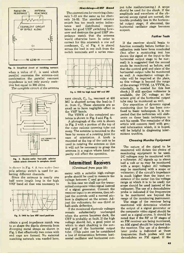
Fig. 3: Simplified circuit of matching network
when a value of C, is used which parallel resonates the antenna-coil combination the parallel resonant impedance is not only purely resis-tive but equal to 300 ohms. The complete circuit of the antenna
Fig. 4: Double-wafer four-pole selectro switch selects channels in complete circuit
is shown in Fig. 4. A Iwo ware'. [mu' pole selector switch is used for se-lecting different channels.
Since the antenna is nearly one half wave length long in the high VHF band all that was necessary to
•
s.
eiD 110
.MR11
re ,
ege•C•tal,
Fig. 5: SWR for low VHF bond positions
obtain a good impedance match was to so shape the dipole elements from diverging metal straps as shown in Fig. 1 that effectively two cones with end caps are formed. No external matching network was needed here.
Matching—II 111F Band
The connections for receiving chan-nels 7-13 are the same as for chan-nels 14-83. The standard selector switch has too much series induc-tance and distributed capaci-tance for good UHF switching how-ever and destroys the good UHF im-pedance match that the antenna would otherwise have. In order to correct for this mismatch a one uuf condenser, C, of Fig. 4 is placed across the lead in one inch from the switch terminals and a series reso-
f vet!
tee Y. .14.‘, WO WO FOO 800
Fig. 6: SWR for high band VHF and UHF
nant circuit, C3, L3, resonant at 400 MC is shunted across the lead-in 7 in. from C.,. These elements are so small as to have negligible effect in the VHF bands. The VSWR of the completed an-
tenna is shown in Fig. 5 and Fig. 6. A photograph of the unit is shown
in Fig. 2 with a portion of the top of the outer radome covering tube cut away. The antenna is mounted to the base by means of a rotating joint for ease of orientation. A knob is mounted at the top of the unit to be used in rotating the antenna so that it will not be necessary to grasp the antenna in a region where hand ca-pacity will effect the operation.
Intermittent Receivers (Continued from page 33)
meter with a suitable high-voltage probe should be used to measure the voltage between C and ground.
In this case we shall use the trans-mitted composite video signal instead of a signal generator. Connect the receiver input to an antenna, then ad-just the controls until a normal pic-ture is displayed on the screen. Ad-just the voltmeters for one-third or half-scale deflection.
If the monitored electrode voltages remain substantially unchanged when the screen becomes dark, the CRT is probably at fault. If the high voltage should fail, a good point at which to start checking is the con-trol grid of the horizontal output tube. (This point can be considered a line of demarcation between hori-zontal oscillator and horizontal out-
put tube malfunctioning.) A scope should be used for the check. If the amplitude and waveform of the ob-served sweep signal are normal, the trouble probably lies in the horizon-tal output stage; if abnormal, the horizontal oscillator stage becomes suspect.
Further Tests
If the receiver should begin to function normally before further lo-calization tests have been concluded (but after a monitoring test has shown the signal at the input to the horizontal output stage to be nor-mal) it is suggested that the second anode be monitored as before, and that the control grid and plate of the horizontal output tube be monitored as well. A capacitative voltage di-vider will be required at the plate, as this voltage is beyond the range of the average VTVM. (A VTVM, in-cidentally, is needed for this last check.) If still another voltmeter is available, the DC voltage at the screen grid of the horizontal output tube may be monitored as well. Our exposition of dynamic signal
monitoring thus far has been con-fined to basic techniques. It is ex-pected that the technician will elab-orate on these basic techniques to suit his needs. The remainder of this article will concern itself with gen-eral information which, it is hoped, will be helpful in diagnosing inter-mittent troubles.
Choosing Monitor Equipment
The nature of the signal to be monitored will dictate the choice of monitoring equipment to be used. DC voltages may be monitored with a voltmeter. AC signals up to about half a volt or so may be monitored with a scope; higher AC voltages may be monitored with a scope or voltmeter; if the circuit's impedance is much higher than the input re-sistance of the meter (on the voltage range at which it is to be used) the scope should be used instead of the voltmeter. The use of a demodulator probe is indicated if the frequencies to be monitored are beyond the range of the monitoring instrument. The stage of the receiver being
monitored will determine whether the output of a signal generator or the composite video signal should be used as a signal source. It should be noted that if the RF or IF stages of an FM receiver are being monitored, an AM signal should be injected into the receiver. The use of a demodu-lator probe is indicated at these frequencies. Such probes will not demodulate an FM signal. If the
4$

audio stages of the same receiver are to be monitored, a frequency-modulated signal should be injected at the receiver's antenna input. Monitoring intermittent sync
stages suggests the use of the com-mercially - transmitted composite video signal. It is a convenient signal source, and is far more stable, in our opinion, than most test equipment found outside the laboratory.
It has been assumed that three voltmeters are available in the tech-nician's shop. If this is not the case, two voltmeters, or a scope and a volt meter, may be used, at the expense of the amount of intelligence that may be simultaneously obtained. When a scope is used, the outline of the intelligence being displayed should be indicated with a china pen-cil, for future comparison purposes. The home servicing of intermittent
receivers is not recommended, as it is not practical, economically, to wait for a receiver to become intermittent in the customer's house.
Clues from Set Owner
Information obtained from the owner of the intermittent receiver is often of material value in diagnosing trouble. If, for example, a receiver of the intercarrier sound type has intermittent sound, information as to whether the picture is simulta-neously affected would be helpful. If the picture is not affected, we may conclude that the source of trouble is between the sound take-off point and the speaker. We now have two definite points between which to monitor the sound signal. Thus far, we have considered cases
where only the amplitude of the sig-nal has changed. Signal monitoring need not be confined to this type of intermittent. Waveform distortion, frequency changes, etc. may also be monitored. Such monitoring involves only a minor extension of the tech-niques previously discussed. A min-imum of two scopes and two volt-meters are required for this type of monitoring. A VTVM with a prop-erly isolated DC probe should, of course, be used when a tuned cir-cuit—the RF oscillator tuned grid circuit, for instance—is monitored. The scopes are connected between the points where it is suspected that the signal modification is taking place. The signal waveform originally displayed should be outlined with a china pencil. Appropriate electrode voltages should be simultaneously monitored with the voltmeters to in-dicate a definite correlation between the signal modification and electrode voltage changes, if any.
It should be noted that while a
voltmeter and scope, with or without a demodulator probe, will load a re-ceiver to some degree, this loading is constant, Although the output of the receiver will consequently be at-tenuated. the attenuation, being a function of the loading, will also be constant and will not interfere with signal monitoring. In rare instances, critical circuits (a horizontal AFC circuit, for instance) may require temporary readjustment to com-pensate for this loading, but this is ordinarily not necessary. Although we have discussed only
basic monitoring instruments, more elaborate equipment may be used to monitor and record information. An audible alarm to indicate a signal change may be incorporated, if de-sired. Such equipment has been de-signed and built by the writer, and can be similarly worked out by tech-nicians, without too much difficulty.
Phono Motors (Continued from page 37)
of the turntable should be smoothed down with emery cloth. The turntable must "grip" the
record, so that the latter turns at the exact same speed as the turn-table. If there isn't enough grip, the weight of the pickup arm will cause the record to slip, producing wow. This grip is brought about by the flock (furry substance) that is sprayed over the top of the turn-table. If the flock wears off, the turntable should be re-flocked or replaced. Sometimes mechanical noises, re-
ferred to as rumble, are too slight to be heard at their point of origin; when transferred to the pickup cartridge and amplified, however, they become annoyingly noticeable at the speaker. The presence of rumble may be checked for as fol-lows: 1—Set the record player in operation. 2—Place the pickup arm on the run-off grooves of the rec-ord. 3—Turn up the volume only so far that the surface noise of the rec-ord is barely noticeable. 4—No rum-ble should now be heard.
It is important to note that the size of the various parts of the record player helps determine the speed of rotation of the turntable. Because of this fact, the identical replacement parts supplied by the player manu-facturer should be used.
ABC's of Transistors (Continued from page 35)
from the base.
The circuit arrangements for both types of junction transistors are the
same as for the point-contact type. Electron motion within the junction types is different, however (see Fig. 5). In P-N-P units, electron holes are produced by the emitter. These holes flow through the center crys-tal layer to the collector contact which is the minus terminal of a DC source voltage. The signal voltage applied to the emitter-base circuit governs the number of electron holes which move from emitter to collector. The number of holes flow-ing at any instant determines the current conductivity of the collector circuit. In normal operation the col-lector (output) circuit current is many times that of the emitter (in-put) circuit. In N-P-N transistors, the action
is similar to that of the P-N-P type except that: 1—the battery polari-ties to the emitter and collector are reversed; 2—the action of holes and electrons within the germanium is reversed, and 3—the direction of current flow in the emitter and col-lector circuits is reversed. This op-posite but similar electron action of P-N-P and N-P-N transistors makes it possible to develop com-plementary circuits using pairs of P-N-P and N-P-N units.
Two-Stage Audio Amplifier
A recent development utilizing these complementary properties has four junction transistors, with no other components, working as a two-stage audio amplifier feeding a loudspeaker. Junction transistors can boost
output signal power up to 10,000 times the power of the input signal, a gain of 40 DB. Junction transis-tors make more stable amplifiers than do the point-contact variety and introduce much less noise. They are most effective as low and me-dium-frequency amplifiers and re-quire much less operating power than point-contact types. Junction transistors will probably be most useful in the low-frequency circuits of radio and television receivers, in all types of audio amplifiers and hearing aids and wherever good amplification of the low-to-medium frequency spectrum is desired. Transistors are not now directly
interchangeable with vacuum tubes and there is little likelihood that they will be for some time. The principal reasons for this are that transistors are low-impedance cur-rent amplification devices; their characteristic curves are different (more linear) from those which are associated with tubes; and their in-put and output impedances and gains vary at different operating frequencies. All of these facts mean
46

that circuits must be redesigned to take advantage of the benefits of-fered by transistor use. These bene-fits are:
1. They have no filaments. 2. They consume very little op-
erating power. 3. Heat output is very low because
of absence of filaments and low op-erating power consumption.
4. The life expectancy, in normal operation, will be three to four times longer than for tubes.
5. Physical size is very much less than that of most tubes.
6. No warm-up period is required. Operation starts as soon as power is applied.
7. Rugged construction. Transis-tors can withstand vibration and shock well.
8. Improved circuit designs are possible because of N-type and P-type germanium characteristics.
9. Simplified circuit design is pos-sible, since fewer components are required when transistors are used, and the latter are readily adapted to printed-circuit arrangements.
Transistor Drawbacks
The disadvantages of transistors are few. The principal ones are:
1. High temperatures will perma-nently alter a transistor's charac-teristics.
2. Moisture and dampness will produce similar characteristic changes. This obstacle has been overcome by hermetic sealing of the outer casing.
New Circuits
For most electronic technicians, the commercial use of transistors will mean that new circuits will have to be mastered. There will probably be no sudden revolution, with transistors suddenly displacing all tubes. The indications are rather, that chassis will appear with one or two germanium transistors at first, the number increasing over the next few years. Most important will be the new applications for electronic equipment made possible by new circuits developed around transis-tors. Small personal radios, TV re-ceivers and two-way communica-tion sets are a few of the products which may appear in the immediate future, as a result of chassis minia-turization using transistors and printed circuits. There is every prospect that vast new fields may be opened up, as happened when vac-uum tubes first made their appear-ance. For the alert technician, this is going to mean new challenges, op-portunities and sources of profit.
Ringing Pro blems (Continued from page 23)
Fig. 8—Sketch showing resistance and capaci-tance associated with deflection coil circuit.
the individual peaking coils, using a bridging resistor in a manner sim-ilar to the bridging condenser used in checking for open condensers. This bridging resistor should have a value about eight times as great as the resistance in shunt with the peaking coil; a resistor ten times as large may not always produce enough of a change. Note that con-ventional resistors have a tolerance of about 20 per cent. The bridging check just described
will determine whether or not some coil circuit is not sufficiently damped, and is primarily responsible for the ringing. In cases where bridging any coil produces about the same decrease of ringing intensity as when the others are so tested, it is advisable to reduce all the damp-ing resistors by about the same
Fig. 9A—Sketch showing resistance and capa-citance associated with peaking coil circuit. B—Increasing resistance in shunt with coil.
PEAKING COIL7 rSHUNT RESISTOR
Cshunt
t
Cshunt IS MADE UP OF INTERELECTRODE CAPACITANCE, PEAKING COIL SELF-CAPACITANCE AND STRAY WIRING CAPACITANCE
(A)
PEAKING COIL L IS WOUND OVER SHUNT RESISTOR R
/—ADD RESISTOR
L
ii—j= CONNECT PEAKING 4-COIL TO NEW RESISTOR
(8)
value—do not excessively over-damp one coil circuit alone, in order to get by with only one resistor. Conversely, in some areas of low
signal strength, an increase in ring intensity may be desired, to improve the picture contrast; the procedure in such a case would be to increase the value of the parallel damping resistors, preferably raising all of them the same amount. A practical way of doing this is to disconnect the peaking coil lead from the pigtail of the resistor around which it is wound; attach the resistor to be added to the freed resistor pigtail; then connect the free end of the peaking coil lead to the pigtail of the new resistor (see Fig. 9B).
It should be noted that ringing may arise in the video i-f amplifier; this receiver section should be checked for proper alignment, if resistor bridging tests similar to the ones just described yield negative results. Summary. Some important points
relative to ringing circuits are enumerated below for the conven-ience of the reader:
1. A circuit must possess induct-ance and capacitance in order to be able to ring, regardless of whether or not such parameters are shown on the schematic.
2. The frequency of the ring is determined by the inductance and capacitance of the (resonant) circuit.
3. Ringing circuits are excited by a change in the current flowing though them; a change of voltage across such a circuit will obviously cause such a change in current.
4. Proper frequency adjustment of a ringing circuit permits it to ring in phase with the shock pro-ducing the ring.
5. Since ringing circuits do not amplify, the initial half cycle is the maximum half cycle or alternation. Succeeding alternations must decay relative to this first alternation, due to voltage dissipation across the re-sistive element present.
6. The rate of decay of a ringing circuit—i.e., its damping effective-ness—is determined by the ratio of resistance to the inductance and capacitance present in the circuit.
7. Damping—decay rate—is in-creased by increasing the series re-sistance, or by decreasing the paral-lel resistance. Both shunt and series resistance, when present in the same circuit, may be altered to produce the desired damping rate.
8. A circuit which possesses re-sistance, inductance and capacity cannot ring or oscillate if the damp-ing exceeds a certain critical value; a condition known as overdamping is present in this case.
47

Color Picture Tubes (Continued from page 11)
Fig. 4—Views of mask-and-screen assembly as seen from the deflection points of the three beams. View from deflection point of (A) blue gun, (B) green gun, (C) red gun.
connections may be made. Before applying voltages to the
tube, the grid-No. 2 controls are turned to zero and the grid-No. 1 controls to their maximum negative positions. Then, the proper poten-tials are applied to the electrodes of the tube, and sweep power is per-mitted to reach the deflection yoke. Initially, some arcing or sputtering may be observed. This is a normal reaction.
After allowing sufficient time for the various supplies to stabilize, the grid-No. 2 voltage of the red gun is slowly increased, and the grid-No. 1 bias simultaneously reduced until the screen is illuminated. The next step is the adjustment of
the purity coil. The servicer will probably be told to make this adjust-ment as follows:
1. Pull the deflection yoke back from the funnel of the tube ap-proximately 1/2 inch. 2 Energize the color-purity coil. 3. Move the purity coil along the neck of the tube, while simultaneously rotating it, un-til the purest red field is obtained in
the center of the screen. It will be noted that the pattern on the screen also contains alternate blue and green fields extending radially out from this red center. 4. Slide the deflection yoke in the direction of the face plate until the most uniform red field is obtained over the entire screen. Once the most uniform red field
is obtained, slight readjustment of the color purity coil may be re-quired to achieve optimum color purity. The adjustment may be made by varying the current through the purity coil or by addi-tional movement of the coil. After obtaining optimum purity of
the red field, the blue and green fields should be separately checked. No further adjustment of the color-purity coil should be necessary.
Convergence Adjustment
Convergence is the next char-acteristic to be adjusted. This ad-justment procedure must be made in two separate parts. Convergence adjustment is facilitated by use of a spot generator. This spot genera-tor should be capable of producing equally-spaced horizontal and ver-tical rows of spots on the phosphor screen. Each of these spots contains individual red, blue, and green com-ponents. Proper convergence is at-tained when the three color com-ponents are superimposed.
Initially, the static convergence voltage is adjusted so that spots near the center portion of the screen are converged. If this condition is not obtained, the beam-positioning magnets should be adjusted until the spots within a small central area of the screen are converged. Dynamic convergence can be op-
timized after the static convergence is attained. Horizontal dynamic con-vergence is obtained by adjustment of the waveform and amplitude of the horizontal-dynamic-convergence voltage. This voltage should be varied until each spot of a horizon-tal row near the center of the screen is converged. Vertical con-vergence is attained by varying the vertical-dynamic-convergence volt-age until each spot of a vertical row near the center of the screen is con-verged. Because of the interaction between the horizontal-and-verti-cal-convergence adjustments, it is recommended that these adjust-ments be performed alternately un-til optimum convergence is obtained. The final adjustment of the Color-
tron is the setting of the color bal-ance. As was previously stated, the transfer characteristics and bias voltages of the three guns must be
adjusted to produce a grey scale with no color tinting. The following steps should be
taken to achieve color balance: 1. Set each grid-No. 2 voltage at
the same value. 2. Set each grid-No. 1 voltage so that a low-level grey field is obtained on the screen. 3. Increase the brightness level of the composite field on the screen. This may be done by varying a master brightness control, or by varying a signal voltage simultaneously ap-plied to all No. 1 grids. 4. As the brightness is increased during Step 3, observe which color becomes dominant. 5. Reduce the brightness of the field to the level in Step 2. 6. Reduce the Grid-No. 2 voltage of the gun controlling the dominant color. 7. Repeat steps 3 through 6 until no color tinting is observed over the required brightness level. The foregoing adjustment proce-
dure represents the method that achieves the fastest alignment con-sistent with optimum operational quality. After these steps have been completed, further adjustment should not be required. But further adjustment of the various compo-nents can be made to overcome any undesirable characteristics that may result from improper initial adjust-ment.
Pin 1: Hooter Pin 2: Grid No. 1 of red gun Pin 3: Grid No. 2 of red gun Pin 4: Cathode of red gun Pin 5: Cathode of green gun Pin 6: Grid No. 1 of green gun Pin 7: Grid No. 2 of green gun Pin 8: No connection Pin 9: Grid No. 4 Pin 10: Grids No. 3 Pin 11: Grid No. 2 of blue gun Pin 12: Grid No. 1 of blue gun Pin 13: Cathode of blue gun Pin 14: Heater Metal Flange: Anode
MAXIMUM RATINGS—Design-Center Values Anode voltage 20,0.00 volts DC Grid-No. 4 (convergence) voltage 11,000 volts Grid-No. 3 (focus) voltage 5,000 volts Grid-No. 2 (accelerating) voltage,
each gun 500 volts DC Grid-No. 1 (control) voltage, each gun:
Negative-bias value 200 volts DC Positive-bias value 0 volts DC Positive-peak value 2 volts
Peak heater-cathode voltage, each gun: Heater negative with respect to cathode:
During worm-up period not to exceed 15 seconds 410 volts
After warm-up 180 volts Heater positive with respect to ,othode 15 volts
Fig. 2—Basing diagram of Colortron. Maximum voltage ratings of the tube are also shown.
11-RT-• PRINTED IN U.S.A.


RADIO & TELEVISION DATA for
RADIOTRICIANS* & TELETRICIANS*
Registered U.S. Patent Office)
Prepared as a Service
Especially for Members of the
NATIONAL RADIO INSTITUTE ALUMNI ASSOCIATION
Washington 9, D. C.
Compiled by John H. Battison,
Director of Education, National Radio Institute
Reprinted from
TELE-TECH and RADIO & TELEVISION RETAILING
Copyrighted (all rights reserved) by
CALDWELL-CLEMENTS, INC.
480 Lexington Ave.
New York 17, N.Y.

Antenna Considerations Bandwidth, Beam Width and Gain Must All Be
X
• The old saying that there's nothing new under the sun applies to TV an-tennas as well as anything else. There's hardly a type available which wasn't long ago employed by hams, commercial broadcast stations or the military.
Nevertheless, when a type appears which has hitherto not been used, or not been used much, in TV, we tend to think of it as "new." For instance, when the Yagi array was described it was considered to be an innovation, although it was really older than TV itself. And even then, it did not come into widespread use for probably at least another year.
It seems that dealers in the fringe areas, using typical American ingenuity, will try anything to get a few more DB out of the mud (noise to you). Manu-facturers are to be complimented for their courage in presenting many elab-orate new designs in an effort to satisfy the enthusiasm of the DX crowd. Two relatively recent entries in the
DB Derby are the rhombic and the cor-ner reflector antennas. While these have been around for some time, there seems to have been an increase in interest in them last summer, with many techni-cians trying their hands at construction, and some manufacturers offering new models. The rhombic is a paradoxical product
which has some wonderful advantages which would fire the enthusiasm of any wooer of weak signals, but also some disadvantages which would cause any old time radio man to say that it is totally impractical for TV.
Its advantages are broad bandwidth, excellent directivity, good signal-to-noise ratio and high gain. A well de-signed rhombic can have a gain of 16 DB over a standard dipole, a frequency bandwidth to the half power point (3 DB down) of as much as ± 50% from the frequency for which it is cut, and a beam width of about 20 degrees— which is narrow enough for sharp orientation and high gain, but not so narrow as to be supercritical. The im-pedance is about 600 ohms, a good match for the increasingly popular open wire line. And before you get out the pencil to
figure the bandwidth, let's take an ex-ample: with a center frequency of 150 MC, plus or minus 50% would take it down to 75 MC and up to 225.
All the above is on the plus side. What about the disadvantages? The rhombic is basically a long wire an-tenna. In broadcast, communications and amateur work it is often used for extremely long distance transmissions because of its high gain and sharp di-rectivity. In such situations, it would be
Y
X Transmission Line
Terminating Resistor
OVERALL OVERALL LEG LENGTH LENGTH. Y AXIS WIDTH: X AXIS
IA 2 A
rCHANNEL 13: 2A LEGS— 8.-10"
3
4 A
LI A
2.9
5.0
7.0 A
12'-6"
I 30\
2.2 A
2.7
3.2 A
9,-5"
Fig. 2—Typical rhombic designs based on interior angles which complement those shown in fig. 3. When the legs or sides are larger multiples of a wave length at the operating frequency, the antenna gets longer and narrower as does the beam, and the gain goes up. Similarly, when the size remains the same but the frequency goes up: a leg which is 2/. long at 100 MC is 4X at 200 MC.
mounted on four high, heavy poles, and could run from 200 to 400 feet in overall length and width, and about 50 to 75 feet high. You might jump to the conclusion
that TV antennas would be much smaller because of the frequency (and you're right), but you'll run into di-mensions such as those mentioned above in the 5-30 MC band. A rhombus is an equilateral parallel-
ogram, having its angles oblique. In plain English, that is a four-sided figure whose sides are parallel and equal, and whose angles are not right angles (that is, a square is excluded from the defini-tion). In the form in which it is usually
seen, the rhombic antenna resembles a diamond. It is longer than it is wide, and an imaginary line drawn through the long way is called the major axis; through the short way is the minor axis. The direction of maximum reception
is along the major axis; the "front" point is towards the station and the transmission line is connected at the rear point of the diamond. Typical rhombic antenna shapes can be seen in figure 2. The four sides of the rhombic are
called "legs," and each leg is a number of wave lengths long at the frequency for which the antenna is designed. The longer the legs, the narrower the beam and the higher the gain. A corollary to this is that as the
frequency gets higher, the legs get re-latively longer, and the gain goes up. We said earlier that the rhombic is a
"long wire" antenna, and the behavior of such antennas is that the lobes of the
radiation pattern form at an angle to the wire. The longer the wire is (in re-lation to the wave length of the fre-quency to be received) the smaller the angle is that the lobe makes with it, up to 8 wavelengths (see fig. 3). What we desire is to have the lobes
"point" straight ahead toward the sta-tion, and all together (there is one major lobe on each leg). If we con-sider one leg only, we know that when it is on a line with the station, the lobe is pointing away from the station by a certain angle, as shown in fig. 3, accord-ing to the number of wavelengths long it is. If we move it away from "straight ahead" we will arrive at an angle where thé lobe is on line with the station. So the first step in designing a rhom-
bic is to decide how many wavelengths long a leg will be. In TV receiving an-tennas, where both space and money are at a premium, the designer would select the shortest leg he could, while still achieving enough gain over other antennas to make the job worth while. Remember that the shorter the legs, the wider the beam and the less the gain. A probable likely minimum would be 2 wavelengths: L (length of leg) = 2k (wavelengths). A properly terminated Fig. 3—Formation of radiatbn lobes on long wire ant f different lengths with respect to a wave length at the operating frequency.
2

in Fringe Area Reception Taken Into Account to Achieve Optimum Results
"t rhombic could have a gain of 13 DB; 4/. v‘otil(i give 16 DB.
lf the design center frequency were 150 MC. tor instance, X is about 6.24 feet and 2/. would be 12.48 feet. In figure 2 we see that the overall length of such an antenna would be 3.4). or 212 feet, the width would be 2 or 12.48 feet. These figures will give the reader
some idea of the dimensions of a prop-erly designed rhombic. They're rather large, but not impractical. The size of the rhombic really gets cozy when you get up into UHF (and we'll probably see a lot of them later on). At 500 MC, X would be 1.86 feet, a 2). antenna would have an overall length of 6.3 feet and width of 3.72 feet. A typical UHF rhombic is shown in fig. 4. In discussing the size and shape of
antennas, and their gain, bandwidth, etc., we refer, of course, to theoretical designs. In actual practice, manufac-turers may alter the size, shape, dia-meter of elements, etc., to improve on the theoretical design and/or to fit com-mercial *requirements.
Fig. 4—A typical UHF rhombic antenna. The
antenna is "pointing" in the direction opposite the end to which the lead-in is attached.
Design of the rhombic calls for "ter-mination" of the antenna across the front "point" with a resistor of specified size. When properly terminated, the an-tenna is unidirectional, with high front to back ratio. When unterminated, it is bidirectional with a consequent loss of gain in the forward direction. The terminating resistor tends to absorb re-flections which would otherwise destroy the unidirectional characteristic of the antenna. Height of the rhombic, an important
factor at lower frequencies, can be ig-nored at VHF, since getting the antenna higher than one or two wavelengths above the ground is no problem at such frequencies. Having considered the physical ap-
pearance of the rhombic, we might refer again to its characteristics. When con-
Fig. 5—A typical Corner Reflector antenna. Although a very effective high gain unit, this antenna is fairly large and heavy, and therefore is most practical on the high-band channels.— Illustration courtesy Radio Merchandise Sales, Inc.
structed properly and installed under optimum conditions, gain can be as great or greater than most antennas and arrays available, and the band-width is quite broad—not usually characteristic of directional high gain arrays. In many fringe area installations,
optimum conditions might be achieved and considerable advantage attained with a rhombic. As for wide band oper-ation, the writer has not had the oppor-tunity to observe the reactions of the rhombic under such conditions. Most VHF antennas exhibit resonances at certain harmonics of their design fre-quency, and a change in the lobe forma-tion which changes the direction of maximum gain. It is also true that most VHF antennas work poorly below their design center frequency. The rhombic is not supposed to display such charac-teristics, as some tests have shown. The corner reflector antenna is an-
other special type, which is a straight or folded dipole (usually folded, for impedance reasons) with a rather large reflector consisting of a number of ele-ments arranged in two planes so that they resemble a book half open. The dipole is placed at the center within the included angle, or in other words, inside the corner. Gain and bandwidth are relatively high on this type of an-tenna, too. Physical size and weight of the reflector, however, suggest that its use would be confined to high band VHF, or to UHF. The corner reflector is actually closely
related to the parabolic reflector, which
will probably be used considerably in UHF (as it is already in radar), when the size of the "dish" becomes prac-ticable. Gain of an antenna with a parabolic reflector is slightly more than the corner reflector, but the bandwidth is only half as wide.
Vertical pickup on the corner re-flector antenna is practically nil (not so with the rhombic) and front-to-back ratio is very high. A typical antenna for approximately
Channel 13 would have a reflector con-sisting of two sheets or planes at right angles to each other. Each sheet would be about four feet long, each made up of 10 reflector elements 31 inches long, 1/4 inch in diameter and 5 inches apart. A commercial corner reflector antenna is shown in fig. 5. Beam width of the corner reflector
type antenna is relatively wide (com-pared to the rhombic, for instance) with a blunt front, which would make it possible to receive several stations slightly different in orientation from the site. Vertical pickup is smaller than almost any other type of antenna which can be selected, and should be advan-tageous where noise pickup from the ground (as with auto ignition, for in-stance) is a problem. The sheet reflector antenna is a dipole
with a simulated flat sheet behind it (as
Fig. 6—An unusual rhombic in which the long axis is broadside to the station. Extra elements on the back are designed to improve pickup on the low band. By Increasing the diameter of the elements, it is said to be possible to utilize shorter legs.—Courtesy Roger Phillips Research Labs.
opposed to the folded sheet of the cor-ner reflector). The sheet consists of a number of reflector elements in a hay-rack formation very similar to certain types of radar antenna we used during the last war; but with the radr.r anten-na, there were also a great number of driven elements, several elements wide as well as high. Gain of the sheet an-tenna, of which the Gonset Radaray is an example, is not, in theory, as high as either the rhombic or the corner re-flector, nor is the bandwidth as wide. But these factors, in actual field per-formance, would depend on the intrica-cies of the manufacturer's design. Front
3

TV Antennas
to back ratio is very high, and the theoretical. antenna would have no pickup either from the ground or from the rear. Beam width is quite broad and blunt, even more so than the corner reflector.
Part 2:
• The importance of TV antennas in the overall reception chain from trans-mitter to picture tube can be graphically illustrated by citing the example of a certain TV transmitter: the transmitter delivers 2.68 KW of video power tó the antenna, while the effective radiated power is 18.5 KW. The antenna itself thus provides a power gain of 6.9 times (8.4 DB). Gains of as high as 10 DB are not un-
attainable with receiving antennas. Since we are more accustomed to con-sider volts (or rather, microvolts) at this stage of reception, we can interpret this as a voltage gain of 3.16 times. The importance of antenna gain can
be appreciated from a brief analysis of picture reception in the fringe areas. Picture quality can be (and usually is) marred by (1) Lack of contrast, (2) Snow, (3) Interference and (4) Poor sync. All of these troubles can be summed up by the expression "weak signal." Snow and external interference will degrade the contrast by breaking up the solid blacks and whites as if a screen were put over them. Interference can upset sync by injecting relatively high amplitude noise peaks over the weak sync signals. Therefore it can be seen that snow and
external interference can be the seat of most of the troubles. The sources of ex-ternal interference need not be ex-plained at great length. They are such things as ignition, motors (particularly with arcing brushes), unwanted RF sig-nals, etc., and are familiar to the techni-cian.
VHF
Io o
144 7774 II .00 I I I
.GACrcus
/It
4 DB
4
STANDARD + e FOLDED DIPOLE REFERENCE
4
DB
e -lo
MUM Man MUM »MUM.
MIBINIMMIMMElin BMW.... Mali Mr a MOM MUM MM.
11111311111MM4111111111.1iellia\ laZi IMO
BBIIMMIIIMMIMUMIBMIZZZ »1111111111MMUMMIIIIM BM »MUM
111/.*M10% effli201*41ZNyteetelell erieffl.eméditepsommtN,d»ohopm e7,6 II 7s"
Fig. 2: Gain of a simple d pole (90 long) and reflector ove the 12 channe s, compare to "standard" ut for each frequency. Compare this broad-band, low-gain antenna with th
narrow-band, high gain Yogi shown in fig. 3. Illustration courtesy American Phenolic Cow
Snow is, however, internal. A certain level of noise in tubes and resistors is inherent in the design of electronic equipment. Ordinarily this noise is kept at a minmum and is well over-ridden by the signal. In the presence of a weak signal, however, the receiver is operat-ing "wide open" and the higher the gain of the stage, the greater the tube hiss and noise (which manifests itself as snow). In other words, the signal-to-noise (S/N) ratio is already low with a weak signal, and by running the gain wide open, we increase the noise and lower the ratio still further. This ratio should be at least 10:1 at the output of the tuner, which is one of the principal limiting factors on the sensitivity of a receiver. The acceptance of both external and
internal noise is increased as the band-width increases. This makes sense if we consider random noise as occupying a broad band of frequencies. The wider the bandwidth of the receiver, the more of the noise spectrum it will accept. This is why a TV receiver with a 6 MC band-width is so much more susceptible to noise than, for instance, a high sensitiv-ity AM set. Improvement of the signal to noise
ratio must take place prior to the grid of the first IF amplifier, or in other words, in the front end or at the an-tenna. Or to put it another way, this is the most critical spot for S/N, since the signal level is low and the gain is rela-tively low. Any noise passed on by the tuner will be tremendously amplified by the IF amplifier and, if the level is high enough, will appear in the picture. Assuming for the moment that we do
not intend to make any changes in the receiver, then it is obvious that the only way to increase the S/N ratio at the output of the tuner is to increase the signal input to it. This could be done with a better antenna or with a booster.
Fig. 1: UHF TV bond is 2-4 times h gher in fre-quency and almost 3 times as wide as VHF.
Ii IS 14
111 11 II El
UHF TV
70 CHANNELS
ii 82
es 000GAVICIIIS IN
Considered purely as an amplifier, how-ever, a booster would contribute noise of its own, and in addition would am-plify any noise present at the antenna. A booster has certain advantages, how-ever, which will be taken up later. But for improving the S/N ratio, the an-tenna is the likeliest place. Let us assume some hypothetical val-
ues for the sake of clarification. Suppose we have a tuner with a gain of 10 from input to converter plate, and internal noise at the output of al microvolts. A signal input (pure, without external noise) of 50 microvolts would produce an output of 500 microvolts, and this would give us our desired S/N of 10:1. But now let us suppose that the input
signal were not clean, but instead that there was a 10 microvolt noise signal present (actually a very small amount). The signal to noise ratio in the input would then be 50:10 or 5:1. After 10 times amplification by the tuner, we would have 500 microvolts of signal plus 100 microvolts of noise. This added to the 50 microvolts of internal noise would give a total of 150 microvolts of noise. The noise ratio at the output of the tuner would now be 500:150 or about 3.3 to 1, a very unsatisfactory ratio. To overcome a situation such as this
would require a signal of 150 microvolts. With the same 10 microvolts of external noise and a tuner gain of 10, we would have an output signal of 1500 microvolts and a noise signal of 100. This latter, added to the internal noise (50) would give 150 microvolts of noise. 1500 to 150, then, would give the desired 10:1 ratio. To achieve this result, namely to in-
crease the input signal from 50 to 150 microvolts, would require an antenna voltage gain of 3, or about 9.5 DB. A Yagi could do it, or a corner reflector, or several other types of antennas pre-viously mentioned in these pages. Thus it can be seen that an improve-
ment in the signal to noise ratio must be achieved early in the game in order to effect a really worthwhile improvement in the picture. Although increases in amplification may produce more black and white, if the snow and interference are not reduced, detail will not be im-proved and annoyance and eyestrain will be the only results. Antennas may increase gain by cut-
ting down in beamwidth and bandwidth, or both, for they can "reach out" farther. They can also cut down on noise
4

pickup with narrow beamwidth, low -front-to-back ratio and low vertical pickup, since they tend to eliminate the possible areas of noise origination. Re-duced bandwidth also helps to cut down noise pickup, since as we mentioned earlier, it tends to discriminate against some of the noise frequencies. A typical Yagi response is shown in
figure 3. It can be seen that the useful bandwidth of this antenna is hardly wider than the channel it is intended to cover. The antenna is cut for the low side of the channel, which emphasizes the picture carrier, a desirable feature in the fringe. The gain of the antenna, of course, is high. Compare the above with the response
curve shown in figure 2, for a simple dipole and reflector. While not nearly so high in gain, this type of antenna is usable over a great deal of the VHF-TV spectrum.
Illeanowidth I'M Gain
The polar response patterns (horizon-tal plane) in figure 4 show the relation-ship of beam width between a 6-ele-ment Yagi (left) and a simple dipole and reflector (right). These two comparisons, of bandwidth
and beam width, tell the general story for high gain antennas, with a few ex-ceptions. The rhombic has a narrow beam (narrower than the Yagi) but a broad bandwidth (in addition to high gain). The corner reflector an-tenna, also discussed last month, has -both a broad beam and a broad band-width, while still a high gain antenna. These two antennas, probably too cum-bersome for general use in VHF-TV (especially the low band) will no doubt be more widely used come UHF, along with a number of other specialized types not used at all in VHF. UHF will make many exacting de-
mands on the antenna installer, when it arrives. In the first place, the spectrum (470-890 MC) is 420 MC wide, 21/2 times the size of the present VHF band from
channel 2-13. UHF will furnish 70 chan-nels, from 14 to 83. In the second place, signal powers attained at the transmit-ter are as yet relatively low compared with VHF. At the same time, attenua-tion of the signal is greater, so that sig-nal strengths are low comparatively, and 20 miles will probably be a "fringe" area. In addition, reflections and sha-dows are more of a problem, and at-tenuation due to rain, leaves, etc. is much greater. Consequently, antennas will need to be very high gain and very directional, but due to the frequency, need not be large. A half wave length at 500 MC is less than a foot. Attenua-tion in flat twin-lead due to weather-ing has been quite serious, but tubular twin-lead seems to stand up better, and it is likely that the latter will be used extensively in UHF. Attenuation in coax is rather high, but it weathers well, and it is also recommended. Impedance matching will be critical at UHF, and even special lightning arresters are re-commended, so that losses and unbal-ance will not result. Getting back to our fringe reception
problems, it is of course, axiomatic that gain is inversely proportional to band-width in amplifiers. It is also true that noise is inversely proportional to band-width. Therefore it can be seen that by cutting down the bandwidth (that is, by tuning more sharply, or peaking the response), we can not only increase the gain but also cut down on the noise so that we make a two-fold improvement in Sill ratio. In TV, naturally, this means cutting down on picture defini-tion. But if by sacrificing some defini-tion we can improve contrast, cut down on snow and interference and make the sync more stable, it may often be worth it. This is actually done by many TV set owners in setting the fine tuning control for the brightest picture, usually at the expense of the sound as well as picture definition. It is also done, more skillfully of course, by some fringe area servicers, who peak-align the sets for higher gain. There are also some re-ceivers which incorporate a circuit which automatically reduces the band-
Fig. 4: Comparison of a narrow beam (left—c 6.element Yogi, from Tele-Tech) and a broad-beam antenna (right, a simple dipole and reflector, from TV ond Other Receiving Antennas by Arnold B. Bailey). These patterns do not indicate the difference in gain between the two (see fig. 2 and 3).
width when the signal strength is down.
This is the point to which we were referring when we said that amplifica-tion is not the only function of boosters. Many tunable boosters not only permit the user to peak-tune the input for higher gain and narrower bandwidth, but are actually built to provide a nar-rower bandwidth signal. Adding a pre-selector ahead of the front end of the receiver also tends to cut out some in-
VOLTAGE GAIN IN
Oil
14
12
10
e 6
4
2
CHANNEL 4
'eso. 60 Mcit 66 72 78 84
Fig. 3: Response of Telrex Y5X1-4, a 5-element
Yogi tut for channel 4. "P" and "S" are pis and sound carriers. This high gain antenna shows less than 1 DB variation over the channel.
terference signals. Before aligning the receiver, however,
the installer would do well to do all he can with the antenna installation. This, of course, includes picking the highest gain array which will suit the local situation (as to number of chan-nels, frequency of channels, etc.); try-ing additional height; using low-loss lead-in well matched at both ends; keeping lead-in away from roofs and walls (with long standoffs) where they might be subject to excessive moisture; experimenting with tilt of the antenna, both in the horizontal and vertical planes, etc. Regardless of what is used after the
antenna—whatever make set, booster, etc.—best results will be obtained with the optimum antenna installation. At-tention lavished on this detail will pay off in better picture quality, more satis-fied customers, and more dollar profits in the end.
SHOP HINT
Scope Requirement for TV Alignment
"While a wide-band response is es-sential for the observation of sync and blanking pulse shapes, it is well to point out that a scope having a response of plus or minus 10% to 40KC is ample for all sweep alignment work on TV and FM. The sweep curve observed is not RF but is derived from the fre-quency-modulated RF or IF signal by detection, and so it is actually well within the audio range.
5

Latest Transistor Units Preview of point-contact germanium types now in develop-
mental and pilot production stages by five manufacturers
WHILE poring through the daily newspaper one may be highly im-
pressed with the imminence of wrist watch radios and pocket-size TV re-ceivers, devices made possible by the advent of the transistor. As one non-engineering enthusiast put it, "The vacuum tube is a cooked goose!" However, the transistor is presently in a developmental phase, and the state of the art does not warrant the zealous acclamations of an immedi-ately forthcoming technological rev-olution. No one is more impressed with the imposing potentialities ol the transistor than the scientists actively engaged in its study, but their sober evaluations tell us that although the future holds a key role in store for
the crystal triode, much more must be learned before its marvelous abilities become commonplace in our daily lives.
So without sensational fanfare, here are several point-contact ger-manium transistors fabricated by dif-ferent manufacturers. Generally speaking, these units are in a devel-opmental or pilot production stage and not commercially available in the mass production meaning of the word. Junction-type transistors have un-dergone less development to date, and may be considered as being in an even earlier prenatal state so far as well controlled mass production for civilian use is concerned.
ti PHILCO'S potted transistor for video and r-f carrier amplification is enclosed in an impreg-nating plastic. The above picture shows the emitter and collector leads, base pin, germanium
block from which the crystal wafer is cut, and the plastic case. Whisker crimp provides prede-termined contact pressure on the crystal. Elec-
trical characteristics are comparable to prelimi-nary specifications for similar types.
RCA transistors are imbedded In a thermo-setting resin to maintain power gains within a 2 db variation over extreme conditions of moisture,
shock and temperature. Unit measures 0.6 x 0.3 x 0.2 in. and is shown at the right in an
advanced stage of construction before being en-cased in plastic. Operating characteristics of two representative transistors at 25 'C are as follows: emitter volts 0.42 and 0.5; emitter current 1.1 and 0.55 ma; collector volts 20 and 17.5; col-lector current 4.6 and 3.6 ma; power gain 17.9 and 26.5 db.
WESTERN ELECTRIC'S Type 2A transistor functions as an amplifier in the "card translctor" used with the new 4A toll crossbar system for auto-matic selection of routes in long distance tele-
phone dialing. These units are used in conjunc-tion with Type 36 phototransistors which are
activated by light passing through a series of punched cards. The cartridge Type 2A has its base contact connected to the metal shell.
RAYTHEON'S Type CK716 transistor is housed in a brass case, 0.65 in. long and 0.255 in. diame-
ter, which acts as the base. The nickel pins are 0.078 In. apart. The maximum electrical ratings are: collector current — 4 ma; emitter current 10 ma; collector voltage — 40 v.; collector dis-
sipation 100 mw. Operating characteristics with grounded base are: collector current 2.5 ma; emitter current 1.0 ma; collector voltage — 15 V.; emitter voltage 0.5 v.; minimum current
amplification 1.2; minimum frequency response 100 KC; maximum noise figure at 1 KC, 65 db. Considered as a three-terminal network, the maximum to minimum range of direct input resistance is 150-450 ohms; transfer input resist-
ance 25-140 ohms; direct output resistance 10,000-40,000 ohms; transfer output resistance 15,000-70,000 ohms.
GENERAL ELECTRIC'S Types G11 (amplifier and oscillator) and GI IA (counter) transistors have
the following physical specifications: brass case maximum size, 0.35 in. high, 0.16 in. diameter; impregnated with moisture resistant wax; silver plated phosphor bronze pins; connections, base
soldered to case, emitter center pin, collector opposite base pin. Electrical characteristics are collector dissipation 100 mw, collector voltage
(V,) 30 v., collector current 7 ma, emitter cur-rent (I,) 3 ma, emitter peak-inverse voltage 50 v., ambient temperature 40 C. Operating
characteristics for the G11 with grounded base and V, =25, lr=0.5 at 25 C, are as follows: base resistance 200 ohms; collector resistance
22,000 ohms; input resistance 475 ohms; current gain 2.2; power gain 17 db; cut-off frequency 2 MC; noise figure 57 db; minimum dc resistance
in emitter circuit 500 ohms. For the G11 A the characteristics are: base resistance 450 ohms; collector resistance 30,000 ohms; input resist-ance 900 ohms; current gain 2.2; turn-off time less than 2 sec.
6

Fig. la, b: Two developmental printed i-f stages for 25 MC. Connectors and inductors are photo-etched; resistors and capacitors are dip-soldered
Printed Unit Assemblies for TV Etching and silk screening techniques reduce costs and
conserve critical materials in receiver manufacturing. Perform
once of printed stages compares favorably with standard circuits
By W. H. HANNAHS & N. STEIN
Physicis Laboratory Sylvania Electric Products, Inc.
Bayside, N. Y.
RESEARCH in new construction for TV equipment faces strong
conflict with existing methods which have established themselves in practice through gradual evolution. Materials, design practice, and methodology are so intertwined that significant changes introduced into chassis structure must necessarily be done with exacting consideration for the assembly line, purchased materials, and above all the net ef-fect upon costs. Nevertheless, cir-cumstances are pressing for the de-velopment of circuit printing meth-ods suitable for TV. The impetus to improve manufacture comes not only from cost competition but also from shortages of metals and spo-radically from components. The application of unitizing to
equipment design has generally fol-lowed two approaches, (1) the func-tional subchassis and (2) assemblies built around a single tube stage. The functional type designed as a plug-in containing several tubes, such as i-f amplifier, power supply, etc., has received some usage in TV construction. However, its primary contributions to convenience of re-pair and replacement are of greater importance where a great nuniber of identical equipments are pre-sented to closely knit service or-
ganizations, as in military or telephone central office operations. Single stage unit assemblies are pri-marily a means to improve assem-bly. Two notable attempts to intro-
duce a more logical uniformity in the assembly of radio and TV cir-cuits may be seen in the single stage modules patented by Evans (Pat. 1,973,248) in 1934, and more re-cently by Mitchell (Pat. 2,472,021). Both of these are pre-assembled groups of conventional resistors and capacitors related in purpose to the performance of a tube and incor-porated in the tube socket. A more familiar type of unit assembly is the "printed" interstage coupling unit built of silk screened resistors and capacitors on a high-dielectric ce-ramic base. This form has become well known through the Bureau of Standards—Centralab work and is now present in many sets as the in-tegrator circuit. The silk screened unit in its commercial form is, of course, attached to tube sockets by wire leads.
Adapting Technique to Circuit
Each of the silk screening or etch-ing techniques, as we now see them, is best adapted to particular circuit elements. The screening of resistors and capacitors of commercial toler-ances on high dielectric plates has become commonplace. However, in-ductors for 40 Mc and less occupy too much area to be screened on ceramic and are of doubtful use on
plates of high dielectric. On the other hand, selective etching of metal-clad laminates and die-stamping processes are producing inductors and interconnecting wir-ing competitive to wire wound ele-ments. The ease of soldering to etched circuits is also attractive but it is not generally feasible to etch bypass and coupling capacitors from clad-laminates. The cure of resis-tors screened on etching stock is also limited by the thermal stabil-ity of the plastic base. By utilizing the intrinsic process
and material advantages of the silk screen and selective etching methods in the development of a unit assembly, completely printed TV circuits are possible.
In Fig. 1 are shown two develop-mental models of a printed 25 Mc video i-f stage. The connectors and inductors, both single spiral and bi-filars, are photo-etched in an essen-tially planar, cascade design and the clips from a wafer type tube socket are incorporated directly into the plastic base. The above-deck place-ment of resistors and capacitors permits assembly to be accom-plished by a dip-soldering opera-tion, during which the coils are pro-tected with a high-temperature tape mask. Both models have bifilar transformers under the brass tun-ing slug and one has also an r-f choke in the heater line. The choice of flat etching stock as
a base for the unit was not an arbi-trary one. Eighteen three-dimen-
7

erS3'
Fig. 2: (L) Pasteboard models for visual study of various shapes. Fig. 3: (R) Design sketches of dip-soldered assemblies incorporating tube sockets
sional pasteboard models of various shapes were constructed for exam-ination, four of which are shown in Fig. 2. Flat stock was selected be-cause of its ready availability, be-cause of the facility of dip-soldering and riveting additional components thereto, and the convenience of a flat master negative. A doubt might arise as to the actual saving of criti-cal material achieved through the use of sheet copper but the photo-
etching process provides opportu-nity for accurate design of each conductor and inductor dimensions to the actual current carrying loads, which usually results in a slight saving in copper when compared with the universal use of one or two sizes of hookup wire. While design standards have not yet been estab-lished, the current carrying capac-ity of etched conductors is remark-ably high when compared with a
TABLE I: CURRENT CAPACITY OF AN ETCHED COIL Coil data:
Material . . Copper on 1/16 in. XXXP laminate
Coil Diam. .. 1 in.
Line width .. .024 in. Line depth .. .0012 in.
Current, Amps. AC
Duration of test Remarks
1.5 2 hours
Coil cool
to touch
Current density at 1.5 amps =
2.0 2 hours
Slightly
warm
Space between lines 009 in. Inductance 2.0 µh Conductor cross-section .. 29 x 1 0-6 in.
Nearest comparable wire size #35 AWG
3.0 4.0 2 hours 5 min.
Copper be- Plastic
came dis- backing
smoking
52,000 amps/sq. in. of conductor cross-section.
5.0
5 sec. Coil did
not open
or buckle
Fig. 4: Puzzleboards consisting of a harness made up of all elements speed circuit design ./.
wire of corresponding cross-sec-tional area.
Temperature Cheek Results
In Table I are shown the results of temperature check made on a 2 ith spiral, which indicates that it could be operated with a current density in excess of 52,000 amp/sq. in. of conductor cross-section with-out excessive temperature rise.
The problem of designing masters for fine, etched bifilar coils has no doubt been one of the factors re-tarding a more general acceptance of etched circuits. A draftsman has
to spend considerable time with compass and straightedge to draw a spiral, and at best accuracy of de-sign is poor. To eliminate this hand-icap, a turntable apparatus resem-bling a transcription machine has been fitted with two pens to enable the drawing of master spirals, either single or bifilar, to be made in a matter of minutes. A wide se-lection of diameters, line width, space width and turns ratio makes possible a rapid improvement in design.
Master drawings are reduced photographically to a negative transparency of exact dimensions and this transparency is used to photoetch the coils by the now well known process. Table II gives speci-fications and test data for several etched coils designed for video i-f use. Tuning is accomplished by a brass screw with an oversize head. Although the presence of the disc tends to lower Q, the reduction is fairly constant over the tuning range necessary to stagger-tuned circuits. Of general interest to engineers
concerned with printed circuits, four methods of incorporating tube
8

I st. Vet I-F 3rd. VID.1-F STAGE STAGE
FROM 1 — TO
FE :Imwe a ...__., A
Fig. 5: Printed circuit layout and schematic of 25 MC II stage. Jump connections, except from center of coils, have been eliminated. Feed-through busbars go to 8+ and agc
sockets in assemblies to be dip-sol-dered have been devised by modi-fications of commercial sockets and parts. Sketches are shown in Fig. 3. Two basic construction features
are essential: 1. The socket must have mechan-
ical retention to supplement solder-ing; and
2. The lug ends of the clips have to emerge horizontally and in con-tact with the conductors on the base material for soldering to be possi-ble. The designs illustrated accom-plish this with a minimum of rivet-ing or fastening. The most direct approach, Fig. 3a,
is to use a type of wafer socket hav-ing long lugs which may be inserted through punched holes in the deck and bent flat against the conductors. A very neat arrangement results if similar but smaller clips are sepa-rately inserted into the etched lam-inate. This construction, Fig. 3b, was used in the module under discus-sion. Some pin clips require com-pression between two wafers for proper functioning and with this type of clip the upper wafer may be retained as shown in 3c. Molded sockets may be adapted by revising
Winding
Single
Single
Single
Dielar
Bailor
Miler
TABLE II: ETCHED COILS FOR 25 MC IF
Etching Stock In.
XXW laminate
1 oz. copper XXXP laminate
1 oz. copper
XXXP laminate
1 oz. copper
XXP laminate 2 oz. copper
XXW laminate 1 oz. copper
XXW laminate
1 oz. copper
P = Primary Winding
1 1/8
1 1/2
1 7/32
19/64
19/64
19/64
15/32
31/64
29/64
Line width
In.
0.018
Total
number of turns
11 h
62 2.35
0.020 11 70 2.18
0.024 11 65 2.05
0.020 8 P-46 P-2.0
8 S-45 5-1.9 0.010 12 1/2 P-48 P-4.8
12 1/2 S-49 S-4.75
0.020 10 P-58 P-2.9
10 S-54 S-2.75
S = Secondary Winding
these so that they insert from be-neath the deck as in Fig. 3d. To do this the top flange is replaced by a snap-ring and an underside flange is provided by addition of an in-sulated washer which also serves to conipress the lugs flush against the circuit connections.
Conventional Tube Shielding
Tube shielding, when required, may be of the conventional type, riveted to a grounding strip or area provided in the etch pattern, or, as shown in Fig. 3. shield fastening can also be adapted to solder-dip as-sembly without recourse to rivets. Planning the circuit layout for
two-dimensional reproduction is an essential step in printed circuit de-sign and much of this effort is spent in the elementary but time-con-suming process of eliminating cross-overs. Sketches are helpful, but three-dimensional models as previ-ously shown are almost mandatory for proper evaluation of a proposed configuration. To facilitate the re-duction of layouts to simplest form a "puzzleboard," Fig. 4, was cre-ated. This consists of a harness made up of all the circuit elements
Fig. 61 (I.) Complete 'nodule shows etched and silk-screened portions of assembly. Fig. 7: (R) Three interlocked panels mounted In a pair of channel strips
a
9
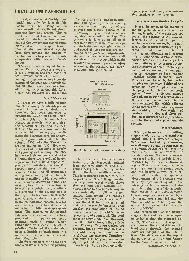
PRINTED UNIT ASSEMBLIES sipate produced heat; a conserva-tive standard is 1 watt/sq. in.
involved, connected at the high po-tential end only by long flexible hookup wire. The starting point is the conventional breadboard circuit separate from any chassis. This is used as a fluid three-dimensional model, in which the free ground ends of the components permit rapid manipulation to the simplest layout. Use of the puzzleboard permits both development and design of printed circuits to proceed at a rate comparable with standard chassis layout. The circuit and a layout for an
etched 25 Mc i-f stage is shown in Fig. 5. Provision has been made for feed-through busbars for heater, B+ and agc. Jump connections from the centers of the coils are unavoidable, but all other crossovers have been eliminated by relegating this func-tion to the resistors and capacitors.
Silk Screening
In order to have a fully printed module retaining the advantages in-herent in the etched deck, silk screening has been employed to produce an RC unit on a high dielec-tric plate (Fig. 8). This unit is fab-ricated on material with a dielec-tric constant of 4,000 and thickness 0.05 in. The material used exhibits a rather high temperature coeffi-cient; the dielectric constant at 85 -C being approximately double the valu. at 25°C, with the "Curie" in-flection falling at 74°C. However, this material is adequate to nearly all bypassing and coupling functions. In the card shown for a 2nd video i-f stage there are a 0.001 IA heater bypass and two 0.005 of bypass ca-pacitors for cathode and screen. The capacity areas on the face of the ceramic as well as all connective wiring have been produced by silk screen stencilling with conductive silver ceramic decorating paint. The second plate for all capacitors is formed by a substantially continu-ous silvering of the reverse side of the high dielectric card. On this, the ground side, windows are provided in the metallization opposite resistor areas on the front to reduce what might be a prohibitive stray capaci-tance. The pattern on the ground side is non-critical and is, therefore, produced by a permanent spray painting mask of simple design rather than by a second silk screen printing. Curing of the metallizing paint is feasible by batch firing in a muffle or in a continuous ceramic decorating lehr. The three resistors on the card are
produced by silk screening printing
of a resin-graphite-lampblack mix-ture. Curing and protective coating as well as the composition of the mixture are closely controlled in processing to give resistors of ac-ceptable commercial stability. The screening is done by an all-metal screening fixture of improved design in which the motion, angle, pressure and speed of the squeegee are con-trolled with precision adjustments. Attempt is thus made to remove all variables in the process which might result from manual operation. After screening, the resistors are cured, insulated, and again baked.
Fig. 8: RC card silk screened on dielectric
The resistors on the card illus-trated are simultaneously printed from the same mixture, and three values being determined by varia-tion of the length-width ratio only. This is sometimes referred to as the "aspect ratio." The 1 K age resistor has a square aspect which shows that the mix used basically pro-duces carbonaceous films having an area resistivity of 1,000 ohms per square. Lengthening the resistive area so that the aspect ratio is 6:1 gives the 6 K input resistor; and making a very wide but short area enables the production of the 83 ohm cathode resistor, which has an aspect ratio of about 1:12. The total range of resistor value on this card, from 83 to 6,000 ohms, is thus a little over 72 times. This approaches the practical limit of variation in resis-tors which may be printed on the card from one mixture. Considera-tion must also be given in the de-sign of printed resistors to see that there is a total area adequate to dis-
11eximior Functioning Lengths
It may be noted in the layout of the RC plate above that the func-tioning lengths of the resistors are set by the spacing of the contacts formed by the conductor pattern, while the widths are set by the pat-tern in the resistor stencil. This pre-sents an additional problem of printing metallization and resistor mix in registration. Absolute regis-tration between the two superim-posed patterns is not of great inter-est but control of the de facto regis-tration of successively printed sam-ples is necessary to keep resistor variation within tolerance limits. This is accomplished by two regis-ter pins on the work holder of the screening fixture plus vacuum clamping which holds the work against these pins. Screen stencils for both capacitor and resistor areas are made on conventional bichro-mate sensitized film which adheres to the screen after contact exposure and washing out. Preparation of masters by drawing and photo re-duction is identical to the procedure used for the etched copper laminate section.
Performance
The performance of unitized stages made up of the combined etched and silk screened compo-nents was checked by measuring overall response and i-f response in a Sylvania Model #1-387 receiver. with substitution of printed for standard stages. The performance of the second video i-f module is rep-resented by test results shown in Fig. 9. The solid curves are for a circuit containing the printed stage, and the broken curves for a set with all standard components. Measurement of i-f response was made by injection of signal at the mixer plate in the tuner, and the point-by-point plot of de potential produced at the 2nd video detector. Overall response was checked by a 30; modulated signal fed into the tuner on Channel 4 setting and the output of the second video detector read by VTVM. The performance of the printed
stage in terms of response is equal to or better than the standard as-sembly. The skirts of both responses are down on the sound side and the bandwidths through the printed stage are adequate at the --3 db level. The difference at the top of the curves is of little significance except that it indicates that the
(Continued on page 43)
10

Germanium Diodes for Indicating Instruments and Relays
DC meters with germanium rectifiers have high sensitivity, wide
frequency range and small size. "Chatter" and "arcing" can be
minimized with dc relays; circuits require small actuating currents
Temp. vs Z — Low
Fig. 1: When a diode operates from a low resistance source into a low resistance meter load, the meter deflection increases with .n-creased temperature, because the diode for-ward resistance decreases with increased tem-perature. The decrease in back resistance which occurs at the same time does not in-fluence the indication to any great extent be-cause the diode hack resistance at eleva ed temperature is still very lurge in comparison with that of the rest of the circuit.
Temp. vs Z — High
Fig. 2: When a diode operates from a high resistance source Into a high resistance load, the meter deflection decreases with increased temperature, because the diode back resistance
decreases with increased temperature. The re-duced forward resistance has little effect on the
meter deflection in this circuit because it is swamped out by the high resistance of the meter load.
Temp. vs Z — Constant
.1 ut I V F- 111. DC SOURCE TO R I i 20 K E oc
Fig. 3: A condition in which the meter deflec-
tion remains practically constant with tempera-ture results from the combined action of two effects. First, the meter deflection tends to in-crease with increased temperature since the diode is working from a low impedance source into the relatively low impedance load of the condenser C,. Second, the decrease in back resistance arts as a load in parallel with R, to effectively decrease the pointer deflection be-cause of the increased temperature. The two
factors work together to produce a more or less constant meter deflection with change in temperature. The load resistance in Figs. 1 and 2 can also be chosen to obtain similar tempera•
ture compensation.
Freq. vs Uniform Output
Fig. 4: The series condenser offers a gradual decreasing input impedance with increased fre-
quency and tends to provide more uniform out-put with change in frequency.
Multirange Rectifier
ACTE R MULTIPILIER
RESISTORS
0.1»l
BLOCKING 2000:1 CAPACITOR METER
Fig. 5: With well spaced components and with resistors of low distributed capacitance and inductance, a multirange rectifier type In-strument with sensitivity of approximately 10,-000 ohms y may give an accuracy w:thin
10% over the frequency range of 60 cycles
to 6 MC.
Maximum Output
Figs. 6o, b: Where maximum output with minimum input is of primary importance, these circuits are suggested for frequencies between
25 cycles and 25 K.C. The circuit of Fig. 6a gives about 10% greater deflection than Fig. 6b, but Fig. 6b is less expensive, takes less room and has somewhat better temperature and frequency characteristics.
liy FRED J. LINGEL
ttttt mercial and Gov't Equip. Dept. General Electric Co.
Syracuse. IV. Y.
BY adding one or two germanium diodes in a suitable rectifier cir-
cuit, dc indicating instruments and sensitive de relays can be used on ac and r-f through 150 MC. Both in-struments and sensitive relays utilize similar techniques for the proper use of diodes, and for this reason both applications are covered in this article.
In measurement applications, a dc meter with a rectifier has several advantages over an ac meter. The biggest one is the increased sensi-tivity. For example, a 0-150 v. mov-ing iron ac voltmeter will take ap-proximately 10 ma, for full scale deflection. A diode type rectifier meter on the other hand can be made with a full scale current of less than 0.1 ma. Other advantages of rectifier type de meters are wide frequency range, good pointer re-sponse, small size and availability for multi-function testers such as ac-dc voltohm milliammeters.
In control applications, ac relays will often chatter and cause arcing. With a dc relay and a properly de-signed diode rectifier circuit, these troubles are eliminated. In addition, the relay can be made to operate on at least % the current and has the advantage of size and weight over an ac relay.
The following list indicates the principal scope of the circuits in the figure indicated:
Figs. 1-3: Temperature effects on diode im-pedance.
Figs. 4-8: Frequency range limited to 25 cycles to 350 MC by pointer oscillation and relay chatter.
Fig. 9: Meter protection from high reverse voltages. ..
Fig. 10: Sensitivity change with different recti-fier types.
Fig. 11: Relay operation with increased sensit:v-ity and no chatter.
Figs. 12-13: Elimination of contact sparking. Fig. 14: Rectifier arrangements for rnlcroameters. Fig. 15: Dimensions of plug-in sealed assembly. Figs. 16-19: Typical characteristic curves for dif-
ferent diodes. Table 1: Condensed specifications for some
germanium diodes.
11
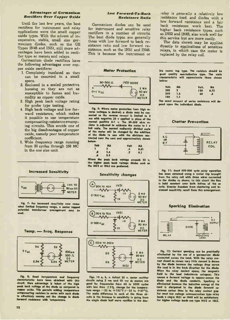
Advantages of Germanium Reedittiers Over Copper Oxide
Until the last few years, the best rectifiers for instrument and relay applications were the small copper oxide types. With the advent of in-expensive, stable, small size ger-manium diodes, such as the GE Types IN48 and IN51, still more ad-vantages have been added to recti-fier type ac meters and relays. Germanium diode rectifiers have
the following advantages over cop-per oxide rectifiers:
1. Completely insulated so they can be mounted in a small space.
2. Enclosed in a sealed protective housing so they are not as susceptible to fumes and hu-midity as copper oxide.
3. High peak back voltage rating for probe type testing.
4. High back voltage and low for-ward resistance, which makes it possible to use temperature compensating resistance swamp-ing circuits. This avoids one of the big disadvantages of copper oxide, namely poor temperature coefficient.
5. Wide frequency range running from 25 cycles through 150 MC in the one size unit.
Increased Sensitivity
Fig. 7: For Increased sensitivity over some-what limited frequency range, a center tapped potential transformer arrangement may be used.
Temp. — Freq. Response
Fig. 8: Good temperature and frequency characteristics have been obtained with this circuit. Here advantage is taken of the high peak back voltage of the diode as compared to copper oxide. This permits adding temperature
compensating resistors in series with each diode to effectively swamp out the change in diode
forward resistance with temperature.
1,1181 Fortrard-To-Bacli Resistanee Ratio
Germanium diodes can be used for instrument and sensitive relay rectifiers in a number of circuits. The best diode types are generally those with low forward to back re-sistance ratio and low forward re-sistance, such as the IN51 and IN48. This is because the instrument or
relay is generally a relatively low resistance load, and diodes with a low forward resistance and a fair back resistance work best. The higher back resistance types, such as IN52 and IN63, also work well for this service but are more costly. The data shown may be applied
directly to applications of sensitive relays, in which case the meter is replaced by the relay coil.
Meter Protection
30 -300 11 IN51 DIODE
2 MA 0-1 Voc Cf)1 50 MV
DC METER
Fig. 9: Where meter protection from high re-
verse voltages is desired, a diode may be con-nected so the reverse current is limited to 3 ma with negative 30 y applied in place of the
normal positive 0-1 v. The 30-300 ohm re-
sistor is adjusted to calibrate the meter to 1 full scale. The normal uniformly divided scale
of the meter will be changed by the addition of the diode to one with the divisions con-tracted near the zero und approximately shown below:
Volt MA Volt MA
1 2 .4 041 .8 1.4 .2 0.1 .6 0.9
Where the peak back voltage exceeds 50 v,
the higher peak bock voltage diodes such as the 1N52 or IN63 are preferred.
Sensitivity changes
Figs. 10 a, b, c: Actual 30 v. meter rectifier
circuits using 2 ma and 50 my dc meters are good for frequencies from 60 to 5000 cycles
with less than ±.-3% change for the tempera-
ture range --25 to +125 °F 1- 32 to +erg. The main difference In each of the three cir-cuits is the increase in sensitivity in going from
the single diode half wave rectifier to the dou-
ble center tap type. The resistors should be
good quality non-inductive type. The scde characteristics will approximate those shown below:
Volt. 300 240 180
MA 2
1.6 1.1
Volt. 120 60
MA 0.75 .4
The exact amount of series resistance will de-pend upon the individual diode.
Chatter Prevention
Fig. 11: Good 400-800 cycle relay operation has been obtained using a center tap brought
from the relay coil with three wires connected to the diodes as shown. In this circuit the flux is held constant over both halves of the ac
cycle. Greater freedom from chattering and In-creased sensitivity result from this arrangement.
Sparking Elimination
Fig. 12: Contact sparking can be practically eliminated by the use of a germanium diode connected across the load. With the relay con-tact closed as shown very little current is drawn by the diode because the voltage drop across the load is in the back direction for the diode. When the relay contact opens, the magnetic field in the load inductance collapses. This
causes a forward voltage to appear .across the
diode and the diode conducts. Sparking is eliminated because the inductive energy of the load is dissipated in the diode forward re-sistance rather than in the relay contact gap. For most low voltage communication type re'ay loads a single IN51 or IN48 will be satisfactory.
For higher voltage loads use type IN52 or IN63.
12

Heavy Loads Plug-in Assembly I-Temp Characteristic
RELAY
DC SUPPLY
R • SOO EACH INDUCTIVE LOAD
Fig. 13: For large relay of motor loads sev-
eral diodes are connected in parallel, still pre-venting contact sparking. The series resistors
help distribute the current more evenly among
the several parallel diodes.
Microammeters
CIRCUIT DC SCALE iheRECTETRIF:irs ULALSCCALE
V MO ACROSSA-6 MO MV
2.5 30 2 23 1,400 165 230 1.5 13 1 6.5 0.5 2.0
2.5 30 2 24 1.5 17 I 10 0.5 4
25 30 2 22 1.5 14
2.5 30 2 23 1.5 17 10 10 .5 3
3,600
3,100
6,700
75 260
160 450
42 270
Figs. 14 a, b, c and d: The meter rectifier circuits shown are suggested for a 30 {to 2000 ohm meter. They may be transposed to either
20 ita or 50 (ta by changing the sensitivity in direct proportion. For example, If the full scale with a (ta 30 meter is 2.5 v., then the full scale
sensitivity with a 20 tta meter will be
2 3 • 2.5 or 1.7 v. This simple ratio does not hold for higher meter currents due to the change in diode resistance. The meter resistance for the three sensitivities is assumed to be
2000 ohms. The ac sensitivity, the series re-sistance and the rectified meter resistance (i.e. with zero series resistance) may each vary
• 15 percent depending upon the individual diodes. All data shown is based on IN51 diodes,
although any other diode with equal or better forward and back resistance will give about the
same characteristics. There is some pointer vibration near full scale in all circuits using the 3 in. undamped meter.
3» MAX
H —'
MAX.
Fig. 15: Where the increased sensitivity of the 4 diode bridge rectifier shown in Fig. 14 d
is desirable, a plug-in hermetically sealed as-sembly may be used. Some typical units are the type 098, IN73 and IN74 with overall di-mensions shown.
E-I Characteristic
Fig. 16: Typical low voltage-current char-acteristic of type IN48 at 25 C.
Eff. Characteristic
Ilefilteeer 0000d.f.41,1
Fig. 17: Typical rectification efficiency-fre-quency ratio characteristics of types IN48, IN52,
and 1N63 at 25'C.
um., nun. et
Fig. 18: Typical reverse current-temperature ratio characteristics with respect to 25 -C.
E-Temp. Characteristic
£00,501 TIMMUTIM f41
Fig. 19: Typical peak inverse voltage-tem-perature ratio characteristics with respect to 25 C.
Condensed Specifications for Some Germanium Diodes
MAX. MIN. MAX.
Forward Back Inverse
Resistance Resistance Voltage
(Ohms) (Ohms)
Type at • 1 V. at - 50V. (Volts)
IN48 250 60,000 85
IN51 400 30,000 50
IN52 250 333,000 85
IN63 250 1 meg. 125
IN65 400 250,000 85
IN69 200 59,000 75
IN70 333 122,000 125
IN72 Tested for efficiency at 500 MC.
IN73 Balanced quad. Very closely matched.
IN74 Balanced quad. Very closely matched.
IN75 400 1 meg. 125
Bench Shortcut for Faster Repairs
Soldering Iron Stand
This "tip" is so simple that I imag-ine a lot of servicemen may have thought of it already. The market has been flooded lately with these spring-clip type holders for holding tools, brooms, etc., on a wall. It occurred to me, when I saw a friend of mine using one to hold his shaving brush in the medicine cabinet, that it might work to hold a soldering iron up off
the bench, and so do away with the rather cumbersome sling that I had. So I screwed one of these clips down on the bench, and I find that it has quite adequate strength to hold my 125-watt iron. You can either hold the iron or the handle, depending on how large a clip you get. The handle is better, as then the clip doesn't conduct the heat away from the iron and into the bench. M. LeGoff, New Orleans, La.
13

Installing PA Equipment Demanding Only Comfortable Listening and Realism, a Well Functioning
• "Often the name auditorium clings to a room which is a marvel of structural engineering; which is perfectly illumi-nated, heated and ventilated; which is provided with every comfort and lux-ury; which is a monument to architec-tural art and beauty; but which is so burdened with acoustical defects that the audition of music is reduced to a confusion of sound and the audition of speech is an utter impossibility." (from "Architectural Acoustics," by Vern O. Knudsen). While this citation is of a rather ex-
treme case, it is nevertheless true that many auditoriums were designed for appearance rather than good acoustical results. And it is also true that many rooms are being used to present music, drama, political speeches, lectures and the like to an audience—or in other words, are being used as an auditorium —which were never meant to do so in the first place.
It is also true that a relatively small number of persons appearing on the stage or at the lecture stand have the requisite control over their voices—as to loudness, sonority and clarity—to make themselves heard by a large audience. As a matter of fact, it is no longer
considered good practice for players to speak their lines so as to "split the ears of the groundlings," as Shakespeare put it.
Sales Potential Seen
For these several reasons, speech and music reinforcement systems have come into somewhat general use. Such sys-tems might be said to differ from the ordinary PA function only in that an attempt is usually made to make such systems inconspicuous—to contribute to the illusion that the listener in the audience is actually hearing the person, the performers or the musicians who are before his eyes. As a matter of fact, many in the au-
dience will actually hear the original sound, without reinforcement. Usually reinforcement will be provided only to fill blind spots and to "boost" the sound to reach distant points. The alert PA dealer will keep his eyes
and ears open to situations which sug-gest the need of a sound reinforcement system, in order to build up his busi-ness with this type of work. A system of this sort will provide a
relatively limited amount of facilities. First, there must be sound pickup at the source of the live performance. The number and placement of microphones will depend on the nature of the sound
source emanating from the stage plat-form. For instance, a lecturer or a political
speaker could have a microphone at the speaker's stand. In a dramatic perform-ance, however, microphones should be invisible, and would have to be placed so that they could not be seen by the audience. In the case of musicians or singers, microphones would have to be placed so as to pick up a balanced coverage of the whole unit.
In the latter case, you must assume that we are not referring to a symphony orchestra, which would probably re-quire no reinforcement, except perhaps in a very large, very poorly designed opera or symphony hall. Rather, how-ever, one might suppose a chamber music group, or individual soloists.
In addition to the live, on-stage pick-up, provision might be required for (1) off-stage pickup of live sound, and (2) off-stage pickup of an electrical sound source such as telephone lines, radio,
• •
.0,00010.0 CCCCC 00C..
PLAN.
1.0a, 0006,001.,«
0'0 .000 II •,1
Fig. 1: Auditorium sound reinforcement system with 2 speakers and 4 mikes on stage.— Courtesy RCA.
phonograph records, etc. These would depend, as we used to say in the serv-ice, "on the tactical situation," or rather on the demands of the users. A third sound pickup need might be in the au-dience itself, as for instance, for audi-ence participation programs, lectures and meetings where the audience is permitted to ask questions, etc.
All the sound pickup sources would feed to a control panel where an opera-tor could mix them, fade them in or out, adjust the level of each, etc. This would preferably be located in the au-dience area, so that the operator can judge the results with his own ears. A power amplifier would then be re-
quired, of course, and finally loud-speakers, located so as to accomplish the desired reinforcement. The possible need for and employ-
ment of preamplifiers between the sound sources and the mixing-control panel will be covered below. For a number of reasons, the use of
several loudspeakers operating at low levels is indicated. For one thing, echoes and interferences between speakers is held to a minimum when the level is low. In the second place, realism is better attained when the PA system doesn't sound like a PA system—in other words, like an artificial sound source. In the third place, this system is designed to reinforce the sound, not to be a substitute for it.
Mang Auxiliary Functions
One other function that this system may be called on to perform—a sub-sidiary feature, and not part of its main function—is to feed the sound which has been picked up and amplified to other places besides the auditorium it-self. In other words, it might feed a recorder, a telephone line, or other rooms in the building, or all three. Here again, the desires of the users will de-termine. We mention these various added fea-
tures of the input and output circuits of the reinforcement system as a sug-gestion to the PA man who is selling the job to the customer. He may be able to "sell up" the job to much more than the customer originally had in mind if he suggests uses which the customer would appreciate but hadn't thought of.
Fig. 1 shows a simple speech rein-forcement system for a small audi-torium. In this installation, six micro-phones feed to a control console on the balcony in the rear of the auditorium. The seating area is roughly 88 feet from the stage to the rear of the balcony and about 96 feet wide. The average height of this auditorium is about 35 feet. Thus the volume of the listening area is roughly 300,000 cubic feet. To produce the level of ordinary speech would take relatively little power out-put from an amplifier (perhaps 1 watt), whereas to simulate the power of a symphony orchestra (as for instance,
14

for Sound Reinforcement System of This Type Should Not Be Conspicuous to the Audience
from a phonograph record, or from the radio), as much as 100 watts might be needed. In this particular case, an am-plifier producing 30 watts with rela-tively low distortion was recommended. Low impedance microphone lines
could be, in this case run all the way from the stage to the control station (88 feet) without undue losses. For ease and versatility of control, it is usually good practice to have a preamplifier stage and an input attenuator for each signal source, feeding into a mixer cir-cuit. In this case there are six micro-phones, and amplifiers with six mike inputs are not very common; as a mat-ter of fact, even preamplifiers of this capacity are rare. Consequently, at least a couple of preamps would probably be necessary. A more elaborate setup is shown in
figure 2. Here mikes 1, 2 and 3 are for
Fig. 2: Wiring diagram for auditorium reinforce-ment system similar to fig. I. Placement of mikes and speakers is described in text.
speech reinforcement on the stage. Mike 4 is for off-stage (live) sound effects and voices (for instance, simulated tele-phone conversations or radio voices). Input 5 is a radio tuner and input 6 is a phonograph turntable, which might be used for sound effects or recorded voices. Either 5 or 6 or both might be used to provide music when a radio-phonograph on-stage is supposed to be turned on.
All the inputs are fed to the control position in the rear of the auditorium, since the operator at that position is in a better spot to judge the level coming out to the audience. In a detailed setup, an intercom would be provided between the back-stage and the control posi-tions. Preamp "A" covers the backstage sound sources, whereas preamp "B" covers the on-stage mikes. The two preamps feed into the power amplifier, which is also located at the control position. A separate power supply is shown, although the preamps and the power amplifier might be self-powered.
The power amplifier feeds six small, low level loudspeakers, well spread around on the sides of the auditorium. These are kept at a low level so as (1) Not to create an unreal, amplified sound where the source is actually supposed to be live performers; (2) To prevent feedback to the microphones, and (3) To prevent room echoes and cancella-tion effects between loudspeakers.
Detail "A" in figure 2 shows a ganged T-pad across the loudspeaker. This type of attenuator maintains a constant im-pedance both in and out, while permit-ting the level to the speaker to be ad-justed.
Selecting Microphone Types Attenuators of this type on each
speaker would permit their level to be adjusted to suit local conditions in the vicinity of the speaker (such as hanging drapes, etc.). They would also make it possible to adjust the speakers in de-scending loudness as they got farther away from the stage, which would con-tribute realism since it simulates the decay of sound in air which would naturally occur. It is usually advised, however, not to place any speakers too far back from the stage, else the illusion of sound coming from the stage would be destroyed.
Fig. 3 shows the circuit of a typical high quality preamplifier with 3 mike input channels and one phono input. As shown, the unit provides for 30-50 or 150-500 ohm low impedance micro-phones. A similar unit, minus the input transformers, is available for high im-pedance mikes. Gain of the amplifier with low impedance microphones is 86 DB at 400 cycles, which is equivalent to an input sensitivity of 121 microvolts for rated output (63 milliwatts). Tone
controls and volume controls are pro-vided for both microphones and phono-graph, and the output of mikes and phono can be mixed. A phone jack is provided so that the operator can moni-tor the amplifier aurally, and an output meter is provided for visual monitoring of the level. As mentioned earlier, the operator would have to depend to a certain extent on his judgment as to the actual sound in the auditorium. It can be seen, however, that with several different input sources, it would be ne-cessary to adjust these individually in order to avoid continuous adjustment of the power amplifier to compensate for the variations in the inputs. It would probably prove most convenient to ad-just all inputs to a predetermined out-put-meter level, and leave the power output level to the speakers more or less constant. Omnidirectional mikes are handy for
picking up sound over a wide area and from all directions. A difficulty may arise, however, which would indicate the need for very directional mikes. This is the fact that omnidirectional, high gain mikes will pick up a lot of extraneous noises, such as the moving of scenery, closing of doors, whispered directions between stage-hands, prompt-ers, etc. This difficulty is often observed on TV programs, where necessity for concealment of not only the mike but its shadow limits the producer in ob-taining optimum results. Such details (concerning the opera-
tion of the system) are, of course, up to the user and not the installer. But the installer should be aware of them so as to properly advise the customer of his needs and avoid future complaints.
Fig. 3: Stromberg-Carlson AV-38 preamp such as might be used in fig. 2, provides input for 3 low
impedance mikes.
TOT •Otarell ropy,. liet
ON /1 TYPTIa
..1
15

Installing PA Part 2: Step-by-Step Outline for Planning,
ISIIPAAIE and PROPOSAL ior
SOUt40 S•fettA
le I ad. et '111,1tieiGiiti(iOreg. Me%
0 veto *use ruse
glitlitSra 1_1 Wet»
Cl Mete r•Sirlo. Gee
otti., jpe
CA•O
$ous°
O
0%0 S
ILA"' Si)
tegee°1' C e stes '''''''' ,
............. .„
....... . .... . ...e.
.......
.........
gAtOPOSe
ISIeet
exe Doe
„,
• The first part of this article outlined the general considerations for audi-torium, theater and other indoor sound reinforcement jobs, and showed how a typical system might be laid out. Now we will take the same typical in-
stallation, and show how the work would be planned, estimated and priced for proper presentation to the customer. The system is shown in Figure 1. As
outlined in part 1, this would be a reinforcement system for a small audi-torium or "little theater." Flexibility and versatility have been added to the simple reinforcement requirement, as shown by the addition of the off-stage mike, tuner and turntable. These could be for supplying sound effects for a play; for supplying "demonstration" material for a lecture; for supplying "between-the-acts" entertainment, etc. Five mikes are provided (four on
stage and one off). In this instance, 4 unidirectional mikes are provided (to avoid the pickup of extraneous noises on stage and to avoid feedback and pickup from the audience) and one "slim" type omnidirectional mike. The latter could be used in the backstage position but would be substituted for one of the stage mikes, should the plat-form be used for a lecturer or musical performer (where an unobtrusive-ap-pearing mike would be desireable). The turntable is a 16" transcription
type, 3-speed, with tone arm and mag-netic pickup. The tuner is equipped with a preamp stage for a magnetic pickup, and the turntable feeds through it. The tuner is an AM-FM type. No provision is made in the installation and estimating sections of this plan for an-tennas. If the location is such that antennas would be required, appropri-ate additions should be made to the parts list, the labor schedule and the overall price.
Features of System
Amplification and control is performed in a position located in the balcony. This position enables the operator to judge the results of the system as it reaches the audience. He also has a good view of the stage so that he can follow a cue sheet if there is one. The on and off stage sound sources
feed to two preamplifiers at the control point. Individual level controls are pro-vided for each source (mikes, phono, tuner), and provision is made for mix-ing them in any desired manner. The preamplifiers (A and B of figure
1) feed into a power amplifier (C) which in turn feeds four loudspeakers at the front of the auditorium. For purposes of concealment and also for realism of sound, these are fairly good quality 12-inch cone-type speakers, mounted in wall baffles. The two which
appear to be on the stage are actually above the proscenium arch. A recorder is shown as optional
equipment. Two preamplifiers are shown for two
reasons: first, amplifiers with more than four inputs are hard to find; second, control is facilitated by having one preamp for off-stage sound sources and one for on-stage; and third, flexibility is provided in that there can be a couple of spare inputs for future changes.
Writing The Proposal
The proposal or "prospectus" pre-sented to the customer should outline the general features of the system as sketched above and in last month's article and should include a plan as shown in figure 1. The list of equipment to be provided can be specific on the actual job, stating make and model number, and some of the manufacturer's specs on the equipment (such as fre-quency response, power output, power consumption, etc.). Some details may be over the customer's head, but will pro-tect the installer from later complaints that he didn't provide equipment as originally promised in the estimate. A typical estimate is shown below. The
prices listed are not actual, but merely exemplary of what might appear on a real job.
Estimate 1 Omnidirectional mike $ 38.22 4 Unidirectional mikes @ 44.10 176.40 1 Mike floor stand 7.64 1 Mike desk stand 2.95 4 Mike wall brackets @ 6.76 27.04 4 12-in speakers @ 27.00 108.00 4 line-voice coil matching transformers @ 3.50 14.00
4 wood wall baffles @ 7.50 30.00 1 Turntable in portable case, 3-speed, with magnetic pickup 100.00
1 AM-FM tuner with built-in preamp for magnetic pickup 100.00
2 4-input preamps for low-im-ped. mikes, with output meters @ 75 150.00
1 15-20 watt power amplifier 100.00 1 Headset for monitoring 15.00 1000 feet microphone cable, lowloss 56.00
500 feet speaker cable, 2-conductor 12.50
Total 937.75 48 Man-hours labor @ 5.00 240.00
Grand total (ESTIMATE) 1177.75
OPTIONAL EXTRA Tape recorder $300-$500 Intercom between balcony and back-stage, with wiring and labor, about $75.00
16

Estimating and Pricing a Typical Auditorium Installation
The labor would, of course, vary all over the lot depending on the nature of the job, the local electrical require-ments, etc. Since this particular job is a low-power one, the voltage on the speaker lines could be kept under 70 volts and conduit should not be needed. As mentioned on page 15, an intercom system could be provided between the back-stage sound effects position and the control position for the purpose of passing on cues, instructions, etc. This is listed as "optional."
For the PA dealer to provide such a complete estimate (we will presume that the list, in actuality, would show actual makes and model numbers) to the customer in advance would actually save him time in two ways. First he would have an actual working list for use in installing the system, and second, a ready-made list for computation of the final bill. The latter would probably only need minor corrections to cover the work actually done and the equip-ment actually installed. Up to this point, certain more or less
technical aspects of the job have been skimmed over. They are: (1) estimating audio power required, (2) determining power handling capacity of loudspeak-
Fig. 1: A typical layout for sound rein-forcement in a small auditorium or little theater. Speakers are above Proscenium arch.
ers, (3) loudspeaker matching problems, and (4) details of wiring layout. The first three of these points have
been simplified by the relatively limited scope of the installation. High power is not required because (1) the size of the auditorium (roughly 100 x 100 x 30) is small, and the audience is small (under 1000); (2) It is an indoor location, and (3) It is only a sound reinforcement system, not a PA system.
In this 300,000 cubic foot auditorium, 10 watts would probably supply suffi-cient acoustic power for the needs, and the 15 to 20 watts recommended in the list of equipment should be able to pro-vide any needs that would arise. This may sound small to the dealer
who is accustomed to supply 10 to 20 watts for a home installation. Full power of that magnitude is practically never actually used in the home, although as much as half of it may be consumed in equalization and feedback. If 10 watts of fairly distortion-free power were available (which might require a 15 or 20 watt amplifier), it should be ample to fill an auditorium of this size. As for the loudspeakers, good quality
12-inch speakers are usually rated for at least 10 watts, and therefore this would present no problem. Actually, connected in parallel, each of the four speakers would draw no more than a fourth of the power.
Speaker Impedance Matching
For the impedance problem, let us suppose that there would be a maximum of 20 watts available, to be on the safe side. There are two ways to figure out the speaker matching problem: one is the old constant impedance method, the other is the newer constant voltage method. The latter is the RTMA-rec-ommended system, and is infinitely simpler for the installer. However, we shall figure out the problem both ways, for the benefit of those who are not using the 70-volt line (the RTMA sys-tem) and also to show how simple the latter is. Under the old way, it would be com-
mon to use a 500-ohm output tap, to take a for instance. Each of the four line-to-voice coil transformers would have 2000-ohm secondaries so that the resultant of the four in parallel would be 500 ohms. If it were desired to have unequal powers among the loudspeak-ers, the problem would be a little more difficult. Let us suppose that we wanted 4 watts each in two of the four, and 2 watts each from the other two, from a 15 watt amplifier. This would be 12 watts, or 12/15 of the total power. If the amplifier output were 500 ohms, then the four speakers should reflect back an impedance which is to 500 as 12:15. 500:X=12:15, then X=625 ohms. The two-watt speakers will absorb 1/6 of the power, the four-watt jobs will absorb 1/3 of the power. The imped-ances, of course, will be just the reverse of this, so the 2-watt speakers will re-quire 6 x 625 or 3750 ohm line trans-former primaries and the 4-watters will require 3 x 625 or 1875 ohm pri-maries.
With the constant voltage, or 70-volt line system, the output tap of the amplifier is selected for the number of
watts required (if it is adjustable; more often, there will be just one output, for maximum output). This is calculated to provide no more than 70.7 volts on the line at maximum output, and lower at
CD 1. Nondirectional—picks up sound with equal sensitivity from oil directions.
2. Sernidirectional (conventional type)—Prac• tically nondirectionol at low frequencies, becoming increasingly directional at higher frequencies.
— 3. Bidirectional—picks up sound from front and rear. Dead at sides.
I 4. Cardioid—microphone has heart-shaped C - pickup pattern—sensitive et front, dead ot
l) rear. Ratio of front-to-reor sensitivity for sounds arriving or random, 7 to 1.
5. Super-Cardioid—Improved cordioid pot-
_ tern. Sensitive at front, dead at rear. Ratio of front-to-reor sensitivity for sounds carriv• ing or rondare. 14 to 1.
Microphone types.—Courtesy Shure Bros., Inc.
anything less than full output. Line to voice coil transformers for 70-volt lines are also marked in watts at the taps, with the impedance arranged for con-nection to a 70-volt line. One has only to select the desired watts for each speaker at its transformer, without re-gard to any mathematics (except that the total watts to all speakers should not exceed the output of the amplifier). Thus in our example, if all four speakers were to get equal power from a 16-watt amplifier, each would be tapped at 4-watts. If unequal powers were de-sired: for instance, two speakers at 2 watts and two at 6-watts, the appropri-ate taps would be selected without any figuring.
So much for the impedance problem. As to the wiring, this will be done with three requirements in mind: (1) The physical make-up of the building, (2) The desires of the customer, and (3) Local codes. It may be that it will not be permissible to put any wires on the exterior surface of walls; or it may be, on the other hand, that it is not per-missible to conceal any wires in the walls; or it may be that existing conduit must be used, or new conduit installed.
It can easily be seen that the choice of one of these alternatives over another could change the cost of the job by 100% or more. Therefore it is obvious that there can be no guesswork here when making an estimate. The wiring plan shown for the job illustrated in figure 1 is merely assumed to be laid by the most direct route along the ex-terior of the walls.
17

The How and Why of Basie Theory Reviewed and Brought Up to Date by Analysis
• In DC restoration (also called DC reinsertion or clamping) something is given back to the video signal, which it lost on its trip to the cathode-ray tube. To know what this something is, we must first make sure that we un-derstand the nature of the video sig-nal, as well as its effect on the CRT.
The video signal contains units of picture information representing light intensities varying from white to black. The white sections of the sig-nal are those that have the smallest amplitude, reckoning from the base-line of the total signal (see fig. 1) ; the black sections of the signal are those that have the greatest signal ampli-tude. The sync pulses have a greater amplitude than the blackest picture signals, and appear in the "blacker-than-black" ,-egion.
Nature of Video Signal
The video signal must be negative-going, when it is applied to the grid of the cathode-ray tube (that is, most negative at greatest amplitude). (If the signal is applied to the cathode, which is 180-degrees out of phase with the grid, it must be positive-going.) Then the black portions of the video signal will drive the CRT grid most negative, causing minimum current to flow through the CRT, and thus pro-ducing least light, or no light, on the fluorescent screen; the white parts of the signal will drive the CRT least negative, allowing maximum current to flow through the CRT, and thus pro-ducing maximum illumination of the picture screen. In this way, the pic-ture recreated on the CRT will have
the same light values as the televised scene. Now, such a charming state of af-
fairs will not occur unless the DC level of the received video signal is the same as the DC level of the cor-responding video signal at the trans-mitter. To clarify this statement, let's analyze what we mean by DC and AC signal levels.
DC Is Reference Level
When an AC signal (fig. 2) is ap-plied to some circuit point, like the grid of a tube, that is at zero potential to chassis, it will cause the grid-to-ground voltage to vary above and be-low zero, in accordance with the sig-nal's AC fluctuations. When the posi-tive half c,f the signal is coming in, the grid voltage will rise above zero in the positive direction; when the negative half of the signal makes its bow, the grid voltage will drop below zero—that is, move in the negative direction. The average level, or the DC level, of the grid signal voltage will be zero, because the voltage ex-cursions above and below the zero level are equal.
If the grid to chassis voltage is not zero, but is, say, —3V, the situation will change. The AC signal will now cause the grid voltage to fluctuate around a level of —3V, not zero. That is, the AC signal will add to, or in-crease, the grid's —3V DC level dur-ing the negative part of its cycle; it will subtract from, or decrease, the grid's —3V DC level during the posi-tive part of its cycle. The average voltage on the grid, or the DC voltage, will now be —3, not 0, as in the pre-ceding case. Now the video signal, after detec-
Fig. 1. Amplitudes of different sections of the composite video signal.
SIGNAL AMPLITUDE
100%
75%
50%
25%
0 %
VIDEO SIGNAL
HORIZONTel- MAXIMUM SYNC PULSE SIGNAL
_ LEVEL
_ _ BLACKER THAN
— BLACK REGION
— BLACK LEVEL 75 TO 80%
TI
MAXIMUM SIGNAL LEVEL
( WHITE REGION, MAX. WHITE IS 25% OR LESS OF MAXIMUM SIGNAL AMPLITUDE )
+ I V.
O — I V.
o
— 2V
— 3V
— 4 V
—3V D.C. VOLTAGE
Fig. 2. (A) An AC signal superimposed on zero DC voltage. 181 An AC signal superim-posed on minus 3 VDC.
tion, has AC and DC components. The AC component is the picture infor-mation itself, which is varying con-stantly due to the amount of light (or absence of it) which the camera at the Xmitter "sees" in the subject. The DC component is the reference level from which the picture signal varies (fig. 3). This DC component is added to the AC signal at the Xmitter, and establishes the brightness level of the televised scene, since it is the average of all the excursions from light to dark in all the lines in one frame. It is therefore also considered to be the level of background illumination of a scene.
DC Component Is Lost
This DC component, when added to the fixed bias on the kine of the re-ceiver (which is established by adjust-ment of the brightness control) es-tablishes the operating point of the kine so that the blanking pulses will cut off the beam. In this way we can be sure not only that the average background illumination of the scene is correctly reproduced, but also that the kine will always be cut off during retrace, and retrace lines will not appear.
If we did not have this DC refer-ence level (and it can be lost, as is explained later on), we should have to adjust the brightness control every time the average background illumina-tion of the scene changed. As it is, the only time we have to change the receiver fixed bias on the kine (or in other words, the setting of the bright-ness control) is when changing from one station to another with a vastly different received signal strength. And
18

DC Reinsertion in TV Sets of Practices Employed in Current .nodel Sets of Various Makers
even this change is made unnecessary (to a great degree) in sets with AGC and/or Automatic Black Level. Now, the indispensable DC signal
level is present at the output of the video detector. Between the video de-tector and the cathode-ray tube, how-ever, the video signal generally passes through one or more R-C (resistance-capacitance) coupling networks. Since a condenser blocks DC, the DC level of the video signal is lost (fig. 4). It must therefore be restored or replaced. This is done by the DC restoration cir-cuit. (It should be noted that in some receivers, no condensers are used in the coupling employed between the de-tector and the cathode-ray tube. No DC restorer is generally found in such set s. )
Restoring DC Manually
To better understand the action of the DC restoration circuit, let's con-sider in detail what would happen if it weren't present. Suppose that light scene was fol-
lowed by a dark scene. The set viewer has adjusted the brightness control while the light scene is coming in, to eliminate vertical retrace lines, and to give an approximately correct rendi-tion of the tonal values present. The scene now changes to a much less brightly lit one. The vertical blanking pulses received during such a scene will no longer drive the CRT bias to cut-off, and vertical retrace lines will be visible on the picture screen (fig. 4). Furthermore, black signals will not drive the CRT grid negative enough to reproduce black on the pic-ture screen. Black and grey tones will therefore be too light.
If the viewer reduces the brightness setting, thereby increasing the CRT bias, the undesired symptoms just de-scribed will be eliminated. When the scene illumination increases consid-erably, however, white and grey pic-ture information will appear too dark, and the background illumination will
Fig. 5. Typical circuit showing how DC res-toration can be restored by grid-leak bias in the final video amplifier, provided direct coupl-ing is used from tile plate of that tube to the grid of the kine.
ZERO AXIS
WHITE
PEDESTALS AT ALL - --u--SAME LEVELS
GRAY
BLACK
-LE
ZERO AX OR
AVERA
S _
Fig. 3 (above, topl. Light medium and dark background pictures as they are transmitted. With the correct DC component included, the black and blacker-than-black information will, as shown, always cut oft the kine in the receiver. Fig. 4 (above, bottom ,. The same signals as in fig. 3, but with the DC component removed, and the signals shown averaged around a zero axis as they would be after passing through a condenser. A, B and C show the DC components which must be added in each case to properly line up the black levels once more.
similarly be too dark. Another re-setting of the brightness control will now become necessary. The DC restoration circuit elimi-
nates the symptoms cited by restoring the correct DC level to the video sig-nals. Two types of DC restorers are in common use: 1—The grid-leak DC restorer; 2—The diode restorer. Let's consider first how the grid-leak re-storer (fig. 5) functions.
Grid Leak DC Restorer
No special circuit is needed for this type of restoration. The DC signal level is restored because of the grid-leak action of R and C. When the composite video signal arrives at the grid of Vi, its polarity is positive (courtesy of the preceding stage or stages). The positive portions of the signal
will drive the grid positive with re-spect to the cathode during the first few cycles, causing grid current to flow, and a negative grid-leak bias to be developed. During subsequent cy-cles, only the positive peaks of the signal—that is, the sync pulses—will exceed or overcome the negative grid-leak bias, and cause grid current to flow momentarily. Now, the grid-leak bias developed is
a DC voltage. This DC voltage estab-lishes a reference level for the video
AC voltage coming in. For correct DC restoration to occur, the DC level must be proportional to the DC level origi-nally present. Let's see how this is achieved.
If we examine the predominantly black and predominantly white signals shown in figs. 3 and 4, we see that the white signal—that is, the signal with a bright background—will, after the loss of its DC component, have a much greater peak-to-peak amplitude than the signal with the dark background. The light background signal has lost more DC voltage than the dark back-ground one, and will need more to be restored to it. In other words, the darker the background of the signal, the smaller is the DC voltage that must be restored to it, and vice versa. Let's see how the grid-leak restorer fulfills this requirement. When a light background signal is
coming in, this high-amplitude signal will produce the largest DC grid-leak bias (since the grid-leak bias is pro-portional to the amplitude of the in-coming signal). On the other hand, with a dark background signal com-ing in, a small DC voltage will be added to the video signal voltage. Thus the correct DC levels are re-stored to the signal, and since direct coupling to the CRT is used, no loss of the restored DC component occurs.
The DC restoration process
19

not only restores the video signal's DC level—it also lines up the vertical blanking and sync pulses, so that they attain the same amplitude. This is the way these pulses are transmitted, and this is how they must be received. If the vertical pulses weren't uniform in amplitude, an inadequately-sized vertical blanking pulse might not blank out the cathode-ray tube, caus-ing vertical retrace lines to be seen on the screen. The necessary lining up of sync and
blanking pulses occurs during the same process that restores the video signal's correct DC level. The grid-limiting action of the video amplifier produces the alignment.
Suppose a large-amplitude vertical sync pulse is coming in. Since the pulse is the most positive part of the video signal applied at the video amplifier grid, and the cathode is grounded, the grid will be driven posi-tive, and grid current will flow. The grid current will be relatively large, because the positive pulse is large. It will produce a voltage in the grid cir-
Fig. 2—Effect of diode DC restorer on CRT bias. C represents a large-amplitude or white-background signal; D represents a small-ampli-tude or dark-background signal. In sketch I, C and D are shown with unrestored DC levels. Note that the CRT bias gives C a DC level of A; D's level is B. In sketch II, C, bucked by a large DC restoration bias, is re-duced to level Al. D, bucked by smaller DC restoration bias Y, is reduced to level Ell. The blanking levels of the two signals are now lined up, but do not reach cut-off. In sketch Ill, the CRT bias has been ad¡usted with the bril-liance control to bring both blanking levels to cut-off.
cuit that is opposite in polarity to the sync pulse voltage. The net sync volt-age will therefore be relatively low.
Fig. 1—Simplified sketch of positive diode DC restorer.
Say the sync pulse voltage is +5 V, and the bucking voltage it produces is —4 V. The net sync pulse voltage will be +1 V. Now let's say that a small-ampli-
tude vertical sync pulse follows its big brother. This pulse will not drive the grid as positive as its predecessor. Less grid current will flow, and the bucking voltage produced will be smaller. Suppose the positive sync pulse voltage is +2 V, and the buck-ing voltage created is —1 V. The net voltage will be +1 V. The two originally unequal pulses
are thus lined up, or brought to the same amplitude, by the grid-limiting action. Small-amplitude pulses are bucked least, and large-amplitude pulses are bucked most, causing all the pulses to line up at the same ap-proximate height. The operation of the diode DC re-
storer (fig. 1) is basically similar to the grid-leak type of restorer. Nega-tive or positive DC restorers may be employed, depending on the polarity of signal needed for correct CRT op-eration. The positive DC restorer illustrated in fig. 1 works as follows: The composite video signal is ap-
plied through C1 between cathode and plate of the restorer (V2). V2 will conduct only when its cathode is driven sufficiently negative to its plate (which is another way of saying that the plate must be driven positive to the cathode), so a negative-going video signal is needed here. During the first few cycles of V2's conduc-tion, a positive charge is built up across C1, making Vo's cathode posi-tive to plate. (This positive voltage between cathode and plate is, in effect, a bias voltage.) When the subsequent video signals applied between cathode and plate are large enough to over-come the positive voltage between cathode and plate, V, conducts. Only the most negative portions of the com-posite video signal — i.e., the sync pulses — will be large enough to over-come the bias voltage and cause V2 to conduct. The resultant DC voltage developed across R1 will be propor-tional to the amplitude of the sync pulses. This voltage is in series with the AC signal voltage applied across
RI. Thus a DC level is added :o the video signal.
This DC level is proportional to tIvi DC level originally present in the sig-nal, for the same reasons that the DC voltage developed in the grid of the grid-leak DC restorer is proportional to the signal's original DC level (ex-plained last month). You may remember that, in our last
article, we pointed out that the darker the original background of a signal, the larger is its DC level; the more DC level it loses in passing through RC coupling networks; and the larger the DC level, therefore, that must be restored to it. Also, vice-versa.
This requirement is satisfied by the diode restorer, because the restorer develops a small positive DC voltage when a dark-background, or small-amplitude signal is coming in (see fig. 2). The negative bias between the grid and cathode of the CRT is low-ered only slightly by this positive bucking voltage that is formed in the grid circuit. The CRT bias therefore remains large, or highly negative, at this time, and the scene is correctly reproduced as dark. When a signal with an originally
light background, or a large-amplitude video signal arrives, the greater con-duction of the DC restorer produces a relatively large positive DC voltage in the CRT grid circuit. This positive voltage substantially reduces the neg-ative bias of the CRT, causing the picture to be correctly reproduced as light. How the sync and blanking pulses
are restored to the same amplitude by the diode restoration process may be explained as follows: The diode re-storer may be considered—in fact, it actually is—a half-wave rectifier, sim-ilar to the half-wave rectifiers used in the power supply of AC-DC broadcast receivers. A large AC input voltage will produce a large DC output volt-age, and vice-versa. The DC voltage produced by the restorer is opposite in polarity to the sync voltage in series with it, and therefore bucks this volt-age. From here on, the explanation is the same as in the case of the grid-leak restorer. A large sync signal will produce a large bucking voltage, and
20

Fig. 3—Simplified grid-leak restoration circuit. Restoration action is achieved through the ac-tion of C77 and R.2. This type of restorer has two basic faults: 1—The plate current of the video amplifier is heavy in the absence of a signal input, which does this tube no good. 2—The control grid and cathode of the CRT will be at the same potential when the video amplifier conks out, causing zero CRT bias and permitting a possibly damaging current to flow through the CRT.
a relatively small net sync voltage. A small sync voltage will produce a small bucking voltage, and a net volt-age approximately equal to that of the preceding sync pulse, etc.
This restorer is called a positive DC restorer because it inserts a positive DC voltage in series with the video signal. In a negative-type of DC re-storer, the action is the same, except that a positive-going signal is needed at the restorer input, and a negative DC voltage is inserted in series with the video signal. The time constant of the DC re-
storer is worth mentioning. R82 and C77 in the grid-leak restorer (fig. 4),
and R8,, and C77 in the diode restorer (fig. 5) determine this time constant.
If the time constant is too short (due to changes—i.e., reductions—in the value of R8., or C77, or insertion of the wrong value of component), the condenser will charge and discharge too rapidly, compared to the time of one horizontal line. The sync and blanking pulses will therefore build up from differently-sized voltage bases, and their effective amplitudes will con-sequently vary.
Normally, the tilae of C77's charge and discharge is so long, compared to the duration of one horizontal line, that the level of the sync pulses is substantially constant.
Too short a time constant is apt to result in a distortion, or incorrect reproduction, of the picture's back-ground illumination. Also, white pic-ture information may appear too dark, and black information too light. Re-trace lines may appear in the picture at different times, due to the differing amplitudes of vertical sync pulse peaks.
If the time constant of R82 and C77 is too long (due to an increase in R82, or the use of the wrong—i.e., too large—value of R82 or C77, DC rein-sertion may not occur quickly enough, and retrace lines may be seen for a short time after a change in the pic-ture's background illumination takes place. The picture's tonal values might
Fig. 4—DC diode restorer used in Philco models 50-T1400, 50-71401, 50-71402, 50-71403. One-half of a 12AU7 is used as a vertical oscillator; the other half as a DC restorer. The triode section used as a restorer is made a diode by connecting grid and plate. A portion of the video amplifier's output signal is fed through R80 and C77 to the cathode of the restorer.
also be incorrect in this brief interval of time.
The correct time constant—T (in seconds) -= R (in megohms) x C (in MFD)—varies from a time equal to the duration of 10 to 20 horizontal lines (the theoretical optimum) to about the time needed for 1 picture frame.
DC restorer trouble should be checked for when retrace lines are seen in the picture after changes in scene lighting occur. To test the re-storer, apply a modulated RF signal, (of the correct frequency for the channel to which the front end is tuned) to the antenna input of the receiver. Then measure the DC resto-ration voltage developed. This is the DC voltage across R8o, fig. 4; and R82, fig. 5. Compare the reading to the voltage developed across the corre-sponding unit in a similar or identical receiver that is operating normally, when the same amount of modulated RF voltage is applied to the latter. If the two measurements are substan-tially different, trouble in the DC re-storer should be looked for.
Since a DC restoration circuit uses very few components, the few possible defects—changes in the value of a con-denser or resistor, or a defective tube —should be readily localized. When a crystal is used in place of a diode, the crystal may become defective. To check it, substitute a known good crys-tal of the same type.
When grid-leak DC reinsertion is employed, trouble in the condenser or resistor will generally introduce other symptoms besides those associated with poor DC restoration. That is, if condenser C77 (fig. 4) becomes leaky or loses capacitance, smearing may be-come noticeable in the picture. If C77 shorts, no picture or a very weak picture will be seen. If R82 increases greatly in value, smearing may occur. If Rw, opens, no picture or a very weak picture is apt to be seen. If R,32 short-circuits, no picture will be seen. If R82 decreases considerably in value,
the picture will become weaker, and smearing may be present.
In the diode DC restorer shown in fig. 5: If R82 loses all or most of its value, the absence of DC restoration may be secondary to the weaker pic-ture that will result, since a large loss in R's value will reduce the signal input to the CRT. An open in Rso will not only impair DC restoration, but is apt to eliminate the picture as well, since the CRT grid return to cathode is opened.
A shorted tube (plate-to-cathode short) will produce the same symp-toms as a short in 1282. A weak or burnt-out tube will cause inadequate DC restoration. An open or consider-able loss of capacitance in C77 will re-sult in the transfer of an insufficient input in the DC restorer, causing in-adequate restoration.
Sometimes the DC restorer and sync clipper are combined in a single triode (see fig. 7). If trouble develops in such a circuit, the impairment of syn-chronization is apt to be far more serious than the absence of DC resto-ration, and the troubleshooter will no doubt be concerned primarily with this first symptom.
In some receivers, the appearance of retrace lines in the picture may be due, not to a defect in the DC restorer, but to a fault in a special circuit whose job it is to eliminate the vertical retrace lines from the picture.
Fig. 5—Circuit commonly employed when DC restoration and sync clipping functions are per-formed by the same tube.
21

Improving the Sound These Modifications Can Better the Response
• For most American homeowners present-day FM-AM combinations are satisfactory, else people would not continue to buy them. But for a con-tinually increasing number of con-sumers, many sets in the middle price range do not produce sound quality as good as these consumers would like. Yet new high-fidelity combina-tions are expensive, costing $400-500, or more. The wide-awake service department
can step in and do a job on existing instruments that is highly profitable, and still save money for the cus-tomer. Modernizing his old set may mean only an hour's labor installing a high quality "tweeter" or loud-speaker. Or it may involve replacing everything except the cabinet (in the case of some inexpensive chassis in-stalled in an impressive cabinet). Usually, though, the changer and tuner section of the set at least, and most of the time even the audio sec-tion, can be made use of. It is in such cases that the greatest advantages to both the service shop and the set owner are to be had from the im-provements discussed in this article. The first step to take in improving
a set with inadequate or distorted re-sponse is to examine it carefully. If a small output transformer is noted, it may be that a larger, better qual-ity transformer is all that is needed. But if the transformer looks OK, is working into a good loudspeaker, and has a pair of tubes driving it, then the circuit details must be checked.
Simple Repair May Do Job
The set may sound bad because of a change in value of almost any com-ponent, or perhaps because of a com-bination of values each just a few percent out of the way from the de-sign centers originally engineered. Therefore a voltage check should be run on the audio stages with the manufacturer's voltage chart. Often changing one or two resistors to give proper voltage readings will improve the linearity and undistorted (5%) output enormously. Assuming that the voltages are in
line with manufacturer's specifica-tions, the first improvements will be the addition of a good output trans-former or of inverse feedback from the present transformer. If inverse feedback is presently employed, but the transformer has a small core, take note of the secondary tap which the feedback comes from. Then em-
Fig. 1. In adjusting inverse feedback 12 ,, is a variable potentiometer. R, and R2 may vary. Some designers recommend omitting R: and connecting R, to cathode. R : equals 123.
ploy the same tap on the new trans-former, if the feedback is of the type which uses the transformer secondary. The output transformer is most
often the weak link in the set. Cheap transformers fail both at the low and high end of the band. They have a tendency to distort and attenuate fre-quencies over 5 KC. They also atten-uate the transfer below 150 cycles very sharply.
Also, the speaker often has a pro-nounced rise in the near-bass region, between 180 and 200 cycles. This rise produces a thump, or "one-note" boominess, an effect which is often made use of to supply the impression of good bass. In fact, a great portion of the public has become so accus-tomed to this false bass that it sounds good to them!
If the installation is one in which a very high quality loudspeaker is to be used, then one of the top grade transformers, of broadcast quality, should be employed. However, in most situations a good medium grade (usually called "standard", or "com-mercial," which are better than "re-placement" grade) output will do, being flat to over 10 KC and good within 4 or 5 db to 50 cycles. This is more than adequate for all but the very best loudspeakers. There is lit-tle point in paying for response of 1 or 2 db flat from 20 cycles to 20 or or 30 KC when it can't be used! Ap-pended is a table showing the impe-dance and approximate price of out-put transformers for various push-pull output stages.
If a medium grade output trans-former, correctly rated at 20-25 watts,
is run at 10 or so watts and less, it will usually display good power trans-fer characteristics.
If the output tubes are running wide open, that is, if no inverse feed-back loop is applied around them, feedback can be added with the as-surance that it will materially im-prove the performance of the receiver. Inverse feedback is one of the most powerful tools known for the reduc-tion of the many types of distortion that arise in audio circuits. There are many ways of adding
this feedback, but the safest method, and the method which is employed today in all conventional top grade amplifiers will be outlined here.
Applying Inverse Feedback In one of these methods a very
small portion of the output signal is taken from the secondary of the out-put transformer and applied back to the cathode of the first voltage am-plifier (or the stage just before the phase inverter). The procedure for determining how much feedback to use, and exactly how to apply it, is much easier than it may sound at first.
Referring to fig. 1, it will be seen that a 200 K potentiometer is con-nected from one side of the secondary to the un-bypassed cathode of the voltage amplifier. (Use the 8 or 16 ohm tap.) An oscilloscope (AC volt-meter will do—need not be VTVM; this is a low impedance circuit) is connected across the voice coil and a tone injected at the first grid, either from a phono test record or an audio generator. The potentiometer is va-
22

of FM-AM Combinations and Performance of Any Amplifier
ried to reduce the resistance between the cathode and the secondary of the transformer to as small a value as is possible without setting up oscilla-tion, and without reducing the gain of the amplifier too much. When the proper setting has been found the resistance of the pot is measured and a fixed resistor is soldered in place. Care must be taken before set-tling definitely on a value for the feedback resistor that there is enough gain left for proper maximum output from the amplifier with the usual program materials, both radio and phonograph.
Alternate Feedback Method
Another method, safer where any but the very highest quality output transformer is employed, takes the feedback voltage off one of the push-pull output plates. In this case again, the feedback voltage is taken back to the un-bypassed cathode of the near-est (to the inverter) single-ended volt-age amplifier stage. The pot used here should be larger, since the source of feedback voltage is much greater. Also, a blocking condenser of .1 to .5, WO V. should be placed between the resistor and the plate.
Oscillation will be shown by any sudden large increase in the output at the secondary terminals. If the circuit oscillates at almost all settings with no signal going in at the input either the primary or the secondary connections must be reversed. This will reverse the phase of the feed-back. (Or use plate of other p.p. tube.)
Power Supply Changes
A more serious defect in some power output stages is the limitation placed on the low frequency output by an inadequate power supply. If this is due to a power transformer having insufficient voltage output, one having proper power and voltage rat-ing may be put in. Such a deficiency may readily be determined by com-paring the screen, cathode and plate voltages with the values shown in the tube manual.
If the filter of the power supply uses one or two heavy resistors in-stead of chokes, the regulation and the efficiency of the power supply can be increased by substituting one or two iron core chokes for the resistors. This is a good modification if the applied voltage to the output tubes is not raised too much thereby. Most of the time this will not happen and the change can be made safely, but
Fig. 2. Dotted lines show various methods for reducing hum due to design not for hum due to component failures). 15-30 V may be applied to 6.3 winding centertap.
check the tube manual to be sure, be-fore making the change. In raising the voltages applied to the screen and plate, be particularly careful to keep the screen voltages no higher than specified.
Another even easier way of getting a little better efficiency, cooler run-ning, and more current out of the transformer without lowering the voltage output is to substitute a rec-tifier which draws less current for its heater supply. Where 5U4s have been used, usually a 5V4 will help. (This method should not be employed in the power supply section of televi-sion or other receivers, where the current drain on the original 5U4 approaches its nominal limit of 225 ma. The 5V4, being rated at 175 ma, is more than adequate for most audio amplifiers, but will becGme low on emission if made to supply most TV sets.)
Also, the slow heating properties of the 5V4 (and 5T4—a higher current-output tube) allow the other tubes in the set to warm up first, and thus
keep from possibly straining the filter condensers. Furthermore, the 5V4 and 5T4 have lower internal imped-ance. Usually, simply plugging one in in place of the 5U4 will give from 5 to 15 volts more on the plates of the output tubes simply because of the lower voltage drop across the rec-tifier. This is a very easy and fre-quently effective way of getting a little better operation (check that tube manual) from the output stage. Many economically designed com-
binations have condensers running from the plates of voltage or power amplifier stages to reduce oscilla-tions which would otherwise be en-countered. And it is frequently found that there are condensers or R-C combinations off the output tube plates. These measures are taken to reduce the operation of the amplifier at the extreme higher frequencies which can often result in distortion or singing. When a new output trans-former has been installed all such counter measures should be removed.
P. P. Output Load (ohms)
6L6 6,600
2A3, 684 3,000
6A5, etc. j 5,000 j
6V6 8,000
6K6 12,000
6F6 10,000
Approx. Cost
Medium Grade
(20-25 watt)
6.00
8.00
5.00
5.00
5.00
Approx. Cost
Top Grade
Transformer
17.00
18.00
16.00
16.00
16.00
23

FM Sound
The most commonly employed method for 60 cycle hum is the use of a wire-wound pot across the heater winding of the power transformer and the adjustment of the center tap connection to ground for minimum hum level. See fig. 2. This is usually effective, but in high-gain preampli-fiers additional steps may be called for. Instead of grounding the adjust-able tap of the 50 or 100 ohm pot, it may be connected to a point of 15 to 25 volts positive. This potential is easily obtained by bridging two or
waft resistors across the B supply. Typical values are 20 to 30 K and 200 to 300 K. Fig. 3 shows this con-nection clearly. The placing of a posi-tive voltage on the heaters ensures that there will be no heater to cathode emission. Since the heater is made positive in relation to the cathode, current can flow, if at all, only from the cathode.
To determine if there is a signifi-cant amount of unbalance in the out-put of a set, all that is needed is a pair of headphones (or an extra loud-speaker coupled to an extra output transformer) and a source of audio tone, either phono frequency record or generator. Bridge the phones (or primary of extra output) across a 1 K, 20 w. resistor connected from the center tap of the receiver output transformer and B plus and feed a tone intot he receiver. If the cir-cuit is unbalanced some sound will be produced in the phones or test speaker. The size of the resistors governing the amount of signal fed into the phase inverter tube are then adjusted to produce no signal in the test phones or test speaker. In Fig. 1, 117 or R. would be the resistor to be adjusted. In fig. 3, R2 would be the proper one.
Improper methods of phase inver-sion to obtain driving voltages for the two output tubes cannot be al-lowed in a good amplifier section. It is assumed that there will be no trick phase inverter circuits left in. One which was employed not long ago in a commercial combination took the driving signal for the grid of output tube No. 2 directly off the cathode of tube No. 1. Another method, not nearly so bad, but still not satisfac-tory, is to take the grid No. 2 signal from the unbypassed screen dropping resistor of output tube No. 1. The best amplifiers today employ
the split load (also known as catho-dyne,) phase inverter, shown in fig. 1. Entirely acceptable results have been obtained with the self-balancing or floating paraphase inverters also. All other phase inverters should be viewed with suspicion if the audio quality is unsatisfactory. The conventional phase inverter
most often commercially-used in the past has closely resembled the self-balancing inverter. But in the self-balancing type the grid of the driver for V2 was grounded through the same resistor as the driver for Vi. In either the conventional type which has the grids grounded separately, or the self-balancing type, the first tri-ode section is the stage which should employ the un-bypassed cathode for application of the inverse feedback. It is highly desirable to apply this feedback voltage back over as few stages (and consequently over as few coupling capacitors) as possible. The cathode most nearly immediately be-fore phase inversion takes place is therefore the cathode to be used. Particularly where the cathode has been grounded and grid-leak bias em-ployed in the voltage amplifier, the cathode should have cathode bias ap-plied, and a suitable (consult the re-sistance-coupled amplifier tables in tube manual) smaller grid return in-serted.
Fig. 1. Split load phase inverter shown Is widely used in high-quality audio amplifiers. Simple to Install, inherently balanced for all but extreme high fre q its. Feedback is applied through Ra to VI.
Since most big sets today use octal or loctal tubes, usually one of the present tubes can be removed and a twin triode installed and wired in place. The phase inverter will be-come the stage immediately preceding the output grids, and the cathode of the triode preceding it should be left unbypassed so that the feedback may be conveniently applied here.
If the phase inversion in the ori-ginal circuit is acceptable but there is insufficient gain for the application of feedback, the gain of one of the voltage amplifier stages may be in-creased by increasing the size of the load resistors. (In general the plate loads should not be made larger than 500,000 ohms.)* Or a twin triode may be installed for the purpose of adding one more stage of amplifica-tion.
Tube Choice for Extra Stage
In choosing a twin triode for either of the above applications the 6SL7 (or 7F7 for loctal) is the best choice. Not only does it draw less plate cur-rent (typically 3 ma. per plate) in-stead of about 10 ma. per plate, but it requires less heater current (.3 amp.) than the 6SN7(7N7) (.6). Also, it has a much higher amplification fac-tor-70, instead of 20. The 6SC7 would be acceptable but for the fact that it has a common cathode.
If the phase inverter is of the type shown in figure 3, referred to here as the "conventional" type (because until recently it was widely used), it may be operating unbalanced due to un-equal aging of the load resistors or tubes. If the circuit had been care-fully balanced when constructed and did not change due to aging, this cir-cuit would allow excellent push-pull driving. But this sort of balancing is not practical in production, due to assembly-line tube and resistor varia-tions. Improvement in this circuit can be made by converting it to the "self-balancing," or "floating pars-phase" type. This conversion is sim-ple, involving only one change in the circuit diagram. In figure 3, the ground return of resistor R3 is lifted, and the grid resistor is returned to the junction of R. and 12,, which is marked point X in the diagram. In the circuit of Figure 1, the cathode of VI would be the proper one to re-ceive the feedback voltage. (In Fig-ure 3, the cathode of the voltage am-plifier.) Today the best sets have both treble
and bass tone controls. They must be capable not only of cutting the amount of treble or bass, but of boosting the bass or high tones, sepa-rately. If the receiver being modern-ized or improved is not equipped with good tone controls, they may be added by inserting the network of Fig. 2, (A) in front of the last voltage am-plifier before the phase inverter. Such a tone control network will introduce about 15 to 20 db loss of gain in the
24

set, so an additional triode stage must be added to compensate for the loss.
Placement of Stage
The extra stage should be placed before the tone controls if possible, so that any possible hum pickup by the components being added for the tone controls will be amplified as little as possible. This tone control net-work is extremely flexible, and will give about 15 or more db of either bass or treble boost or cut (settings of each control are entirely inde-pendent). It may be installed in ex-tremely small space, with the two potentiometers mounted on the con-trol panel—one in place of the old type treble cut knob — and the additional resistors and condensers mounted off the lugs of the pots. One precaution to take is to see that the ground returns in this network are all made to points isolated from chassis, connected with a piece of bus wire, and this run to the ground return of the grid and cathode for the stage they are feeding into.
In many large sets the tone is pleasing to the customer only when the volume is at fairly high levels. If this is because there seems to be a deficiency of bass at the low set-tings of the volume control, a so-called "loudness" control may be added to the combination, in place of the original volume control. The loudness control works on the prin-ciple that the human ear hears less and less of the low notes as the vol-ume is lowered. Consequently the loudness control is designed to give more and more bass boost as the vol-ume is lowered, to keep the apparent balance between bass and treble con-stant at all volume levels.
Some of the better big combinations have had tapped volume controls built in for years. But usually they had only one tap, and so only did the job partly. The most expensive loud-ness controls have twenty-three taps. But it has been found that very smooth action and bass compensation can be had from the proper use of a 500 K potentiometer with only two taps. The diagram in Fig. 1 (B) shows the schematic for this control. The parts may be mounted right on the pot, and inserted on the control panel or chassis in place of the ori-ginal volume control.
Many of the earlier FM receivers employed 6C4 tubes, particularly as local RF oscillators. These were later found to have considerable drift, and frequently became microphonic. So if an FM set has a 6C4, and is giving trouble, try replacing the 6C4 tube. A new 6C4 will usually only clear up the trouble temporarily. Therefore the 9001 or the 6AB4 should be used.
Fig. 2. (Al Independent bass and treble cut or boost controls. Both pots are 1 M, Hat taper. I B "Loudness" control which boosts bass smoothly as volume is decreased. (Circuits engineered by Howard T. Sterling.
Except for pin 5 connection, which is made internally in the 6C4, but not in the other two tubes, the pin connec-tions are the same. Be certain to use a jumper from pin 1 to 5 if the plate connections under the socket are go-ing only to 5.
In addition to the electronic im-provements which can be made in im-proving the sound of FM sets or FM-AM combinations, the possibili-ties of the electro-acoustic improve-ments are great. There is not space here to consider in detail the charac-teristics of the loudspeakers usually employed in the medium range sets. It may be noted though, that the ad-dition of a medium-price extended-range speaker costing from 12-17 dol-
lars will considerably improve the range of a set, once it has been cleaned up electronically. It goes al-most without saying, of course, that substitution of a good low-frequency speaker will help any set. Among the physical characteristics to look for are a large magnet, and a big voice coil (2 to 4 inches; the bigger the better.) Stick to reputable makes. "Bargains" are never cheap in speakers.
*It is inherent in the theory of the split-load inverter that its gain to either side of its load cannot exceed unity, so attempts to increase output by altering its circuit will not succeed.
Fig. 3. Conventional phase inverter frequently employed until recently. Circuit has high gain; is easily unbalanced. Simple change can improve balance considerably.
25

Automatic Gain Control Need for AGC; How the Basic
The automatic gain control circuits in the television receiver keep the output of the video detector as nearly constant as possible. To better appreciate their contribution to optimum set perform-ance, let's consider what might happen if they were absent. In the first place, when the set viewer
switched from a weak station to a strong one, an excessively contrasty picture might result. Worse, the picture might jump, roll, or tear out horizontally, due to overloading of sync stages. Still worse, the picture might suffer a complete loss of synchronization. Such an impairment of sync might be due to a loss of the sync pulses in an overloaded IF am-plifier (see fig. 1).
If the set viewer had switched from a strong station to a weak one, the re-ceived picture might show inadequate contrast. Some loss in synchronization due to the inadequate size of the incom-ing sync pulses might also manifest itself.
Fig. 1—A large•amplitude IF signal may force the grid bias to swing beyond 0 volts, into the positive region, on positive peaks of the signal, and to exceed cut-off, on negative signal peaks. This condition is most apt to occur in the last video IF cmplifier, where the IF signal level is highest. A sharp cut-off tube is assumed.
In either case, resetting of the con-trast control would be necessitated—an extra chore that would scarcely draw sighs of pleasure from tired set owners. By keeping the video detector output
substantially constant in spite of large variations in the amplitudes of incom-ing signals, the need for resetting the contrast control when channels are switched is minimized. Even when the incoming signal increases by a factor of 100, the video detector output will be no more than doubled, in the usual AGC-controlled receiver. When the changes in the strength of the incoming signal are moderate, the output of the video detector will remain substantially constant.
Fig. 2—Typical AVC circuit used in broadcast AM receivers.
Other undesirable conditions that are avoided by the use of AGC include those due to: 1—changes in signal strength caused by fading 2—changes in the gain of various amplifiers produced by slow variations in supply voltages and 3— changes in the strength of incoming sig-nals because of signal reflections from moving conductors, such as airplanes. AGC systems may be divided into
three basic categories: simple AGC, de-layed AGC and keyed AGC. Before we tackle the simple AGC system, a review of AVC action in broadcast AM re-ceivers may prove helpful, because there are several points of similarity between AGC and AVC. AVC, or automatic volume control, is,
as we know, a means of keeping the sound volume constant, in spite of fluctuations in the strength of the in-coming RF carrier. A typical AVC cir-cuit is shown in fig. 2. The detector develops a negative DC voltage across R-1 that is proportional to the strength of the incoming signal. This negative voltage is fed back to controlled RF and/or IF stages as a bias. When the carrier tends to increase in strength, a larger voltage is developed across R-1, causing the AVC bias to increase, and the gain of the AVC-controlled stages to decrease proportionately. The signal output of the detector thus re-mains substantially the same. Similarly, when the incoming RF signal tends to dec..' ease, the lowered voltage developed across R-1 causes a lower AVC bias to be fed back to the controlled stages, increasing their amplification. The signal output of the detector again remains substantially constant as a result. The rate of change of the AVC volt-
age is determined by R-1 and C-1. The time constant of these components de-termines how fast the AVC action will
be. If the time constant is too long (R-1 or C-1 is too large) the AVC bias may not change as rapidly as fluctuations in the strength of the incoming signal, and proper correction will not be maintained.
If the time constant is too small (R-1 or C-1 is too low in value), C-1 will be appreciably charged by low audic frequencies—i.e., low audio frequencies will develop a voltage across C-1, instead of being filtered out. The AVC bias will, in such a case, fluctuate at an audio rate. A feedback of audio signals among dif-ferent stages to which C-1 is common may now occur, and degeneration or oscillation is apt to result, depending on the phase of the different signal cur-rents that pass through, and develop voltages across, C-1.
Fig. 3 (top)—The DC bias developed by an AVC circuit is proportional to the average amplitude of the incoming carrier. The average amplitude of the strong carrier, or amplitude Y, Is greater than average amplitude X of the weaker signal. Fig. S (bottom)—The average level of the TV picture carrier depends on the brightness of the transmitted scene. X, is the average amplitude of the video signal carrier between sync pulses In a dark scene; Y1 is the average amplitude in a light scene.
26

Circuits in TV Sets Control System Works; Typical Circuits
Note that the AVC circuit, under normal operating conditions, develops a voltage that is proportional to the average amplitude of the carrier (see fig. 3). Now, an AGC circuit (fig. 4) must,
like an AVC circuit, develop a bias proportional to the strength of the in-coming signal. A rectifier is employed that changes the applied IF signal into a pulsating DC voltage proportional to the strength of the incoming signal. The pulsating or video-signal component of this voltage is filtered by R-1 and C-1, and a pure DC voltage is fed back to the controlled stages. The AGC circuit, unlike the AVC
circuit, cannot use the average ampli-tude of the carrier as a base or reference level. This is true for the following reason: While the average amplitude of the sound carrier in the case of broad-cast band signals remains substantially constant if the station is not changed, and fading is not present, the average amplitude of the TV picture carrier does not.
Fig. 4—Simple TV AGC circuit.
This is so because the average ampli-tude of the TV picture carrier varies with the average brightness of the scene being telecast. The brighter the scene, the lower the average amplitude of the carrier and vice versa (fig. 5). If the AGC system developed and fed back a DC voltage proportional to the average amplitude of the carrier, whenever an increase in brightness caused the carrier average amplitude to decrease, the re-duced AGC bias fed back to the con-trolled stages would increase the am-plification of these stages, increasing their output, and bucking the tendency of the carrier to decrease. Similarly, when the average amplitude of the car-rier tended to increase, the AGC system would counteract the tendency. The picture's illumination would be incor-rectly rendered in consequence. To avoid such an undesirable con-
dition, the DC voltage output of the AGC rectifier is based on the sync and blanking pulse levels. Since these levels are always of the same amplitude re-gardless of the brightness of the scene (provided that no fading is present, and the station setting is not changed), the
Fig. 6—Commercial form of simple AGC circuit using separate tube for AGC rectifier. Circuit is used in Emerson, Models 6628 and 6638. R12 and C3 form the AGC time constant or filter net-work. R5, Cl and RI are additional units, used to remove video signals from the AGC voltage.
AGC bias developed will be propor-tional to the incoming signal strength, but will not adversely affect the picture brightness.
Let's see how the simple ACC circuit shown in fig. 4 works. The video IF signal is applied between plate and cathode of the AGC rectifier V-1 and causes current to flow during the posi-tive peaks of the incoming signal. A rectifier voltage is consequently de-veloped across R-2. This voltage is pro-portional to the strength of the incom-
ing signal, as represented by its sync and blanking levels. If the incoming signal tends to fade, or fall in ampli-tude, the input to V-1 decreases, and the DC voltage across R-2 falls, re-ducing the bias of the AGC-controlled stages, and thus raising the input to the video detector to its former level—or rather, preventing the input to the video detector from dropping below its former level. Similar bucking changes oppose any tendency of the signal to momentarily rise in amplitude.
Fig. 7—Circuit used in Bendix TV, Models 2051, 3051, 6001, 6003, and 6100. A INGO crystal is employed as a common video detector and AGC rectifier. The and — signs beside the crystal indicate the cathode (—) and the plate (+) sides of the crystal, not the polarities of the volt-
ages developed by the circuit action.
27

Automatic Gain Defects, Symptoms and Troubleshooting Procedures
When the first positive-going signal is applied to V-is input, V-1's plate becomes positive to its cathode, and the tube conducts. C-1 acquires a charge at this time through R-1. When the in-coming signal decreases to the point where V-1's plate is no longer positive to its cathode, the tube stops conduct-ing, and C-1's charge leaks off through R-1 and R-2, developing a negative voltage across these resistors. After several cycles, the charge ac-
quired during V-1's conduction and the charge lost during V-1's non-conduction become equal, and conditions stabilize. The negative voltage across R-2 has, at this time, become large enough to prevent conduction at any time except the peaks of the incoming signals—i.e., the sync pulses. The charge built up across C-1 by
V-1's conduction is approximately equal to the peak amplitude of the sync pulses. Due to the long time constant of C-1 and R-1 (more precisely, R-1 in series with R-2), compared to the in-terval between horizontal sync pulses, C-1 does not have enough time to lose much of its charge before the next pulse comes along and replenishes it.
In between horizontal sync pulses, therefore, CA's charge will not change appreciably. Although video signals are present at the input to the AGC recti-fier at this time, they will not appear at the rectifier's output, because the long time-constant of R-1 and C-1 does not permit the output voltage to change at a video rate.
In this way, video signals are filtered out, and the horizontal sync pulse level determines the AGC bias (since AGC condenser C-1 charges up to practically the level of the horizontal sync pulses). The time constant of R-1 and C-1 is
an important feature of the circuit. If this time constant is too short, C-1 will charge up more, since a shorter time constant for a condenser means a faster charging rate, and a larger amplitude of charge acquired in a given interval of time. Now, under normal conditions, when vertical sync pulses are present at the input to the AGC rectifier, C-1's charge will increase from about 75% of the peak amplitude of the input signal, to 88%, approximately, since these pulses have a large amplitude and a long dura-tion. This is an undesirable condition, because it means that the AGC bias will increase when the vertical sync pulses are coming in, reducing the gain of the ACC-controlled stages at this time. The reduction in gain will persist even when the vertical sync pulses are no longer present, because the charge built up across C-1 cannot leak off instantly. The background shading of the picture will be incorrectly rendered as a result of this condition. The resultant distortion is not too noticeable ordinarily, but if the C-1, R-1 time constant decreases considerably, distortion will be apparent.
• The first problem that presents itself with respect to the servicing of a simple
AGC circuit is: when to look for trouble in this circuit. If a single diode or crys-tal is employed as a common video de-tector and AGC rectifier (see fig. 1), many faults will affect both circuits seriously. When the picture is missing or weak, and other sections of the re-ceiver have been eliminated as possible sources of the trouble, the serviceman will check the video detector, without necessarily thinking of it as an AGC rectifier. When a fault that primarily af-fects the AGC action, without markedly affecting the video detector's operation occurs, however, a test of the AGC operation is called for. Only a few such faults suggest them-
selves in the case of the circuit shown in fig. 1. Changes in the time constant of R-115 and C-110 may be cited as pos-sible defects. If the time constant of this network increases considerably (due to an increase in R-115's value), the ability of the ACC system to counteract changes in the strength of the incoming signal as fast as they occur will be im-paired. When channels are switched, in the event of such a fault, improper con-trast and/or loss of sync may be noted for a short interval, before the AGC regulation takes hold. Momentary fad-ing that was previously inhibited, may now play tag with the picture from time to time, affecting its contrast and syn-chronization.
If R-115 or C-110 loses value, reduc-ing the time constant of the network considerably, vertical synchronization and picture shading will tend to be im-paired. Let's consider what happens in such a case.
Short Time Constant
The normal time constant of a simple, unsophisticated AGC circuit is around a few tenths of a second. If the time constant is reduced to 1/30 of a second or less, symptoms will probably be noted. C-110 charges faster when its time constant is shorter, and a larger voltage develops across it, particularly when the large-amplitude, long-dura-tion vertical sync pulses are coming in. The AGC bias therefore increases, and the output of the AGC-controlled stages decreases, during vertical sync pulse time. The size of these pulses is there-fore reduced with respect to the rest of the composite video signal, reducing the sync pulse input to the vertical oscilla-tor and thus affecting the vertical hold-ing action. The AGC voltage will, in the case
considered, no longer be a relatively pure DC voltage (who is absolutely pure these days?) but will contain a 60-cycle vertical sync pulse ripple in it. This ripple is fed back to the controlled stages, and will tend to modulate the video signal passing through these stages. An undesired low-frequency sig-nal variation that manifest itself in the picture as incorrect background shading may result.
If R-115 decreases to a very low value, C-110 will shunt most of the
video information from R-115, weaken-ing or eliminating the picture. The ef-fect on AGC will be as noticeable, in such a case, as a pimple on a broken arm; the serviceman would, of course, be sending out search parties for the lost video, not the missing AGC.
If C-110 decreases very considerably, its filtering action may be reduced to such a point that feedback occurs in the controlled stages, due to the inability of the decoupling networks to remove the excessive ripple that now appears in the AGC line. The result may be oscillation, if the feedback is regenerative in na-ture; or degeneration (loss of gain), if the feedback is degenerative. Oscilla-tion will tend to manifest itself on the CRT screen as an interference pattern. Similar results are possible but not
likely if one of the decoupling condens-ers loses considerable capacitance. A far more probable effect of such a loss in capacitance is a loss in set sensitivity. This is to be expected because the de-coupling condensers return the tuned grid circuits of the controlled stages to ground. If one of them loses consider-able capacitance, or open-circuits—let's say C-101 does so—much more of the grid signal current will have to flow through a decoupling resistor—in the case just assumed, through R-103, then to C-103 to ground. The Q of the tuned circuit affected will therefore be low-ered, and reduced set sensitivity, pos-sibly even misalignment, may result.
If the faulty decoupling condenser is in the RF amplifier circuit, more noise can be expected, because a reduction in the Q of the tuned circuit at the RF amplifier grid will reduce the signal-noise ratio, and make noise (snow ef-fect) more prominent on the CRT screen.
If R-115 open-circuited, or C-110 short-circuited, no ACC voltage would be transferred to the controlled stages. Not only would improper contrast and impairment of sync tend to occur when channels were switched; overloading of a controlled—perhaps we should say decontrolled—stage might now take place, due to its inadequate bias. Such overloading might manifest itself in the picture as smearing; or it might cause black noise dots in the picture to be fol-lowed by white streamers, making the noise effects more conspicuous. In some cases, one or two ambitious amplifiers might be driven into oscillation when strong signals were coming in, possibly producing negative pictures and various unpredictable symptoms. Open-circuits in decoupling resistors
(such as R-103, R-106) and short-cir-cuits in decoupling condensers (such as C-101, C-103) would also remove the AGC bias from the grids of controlled stages, tending to produce the same symptoms.
If any such symptoms are present, and other sections of the receiver seem to have clean bills of health, the AGC circuit action should be checked. To test the operation of the AGC sys-
28

in Simple AGC Circuits.
tern, the AGC voltage present across C-110 should be measured, and compared with the corresponding DC voltage cited in the set manufacturer's notes. The conditions under which the voltage is measured should be in accordance with those specified in the manufacturer's notes.
If this data is unavailable, an identi-cal or similar receiver, in good working order, may be used as a reference or standard of comparison. The AGC volt-age may be measured in this normal set with a) the antenna connected b) the antenna disconnected, and the antenna input shorted c) the antenna discon-nected, and a signal generator attached to the antenna input terminals. The generator is set at some frequency within the range of the channel to which the front end is set, and its output is reduced to a relatively low level for his check. The receiver under test is then
checked under identical conditions, and the voltages obtained compared with those read on the good set. When the presence of trouble in the
AGC circuit is indicated by such checks, conventional DC voltage, resistance and condenser bridging tests should quickly locate the defective unit. It should be noted, incidentally, that improper oper-ation of a stage preceding the AGC rectifier will cause improper AGC volt-age readings to be obtained. This is true in all AGC circuits, not merely the one shown in fig. 1.
Testing With a Scope
When a loss in capacitance or open-circuit in the AGC filter condenser (C-110) is suspected, a scope may be used to verify if this is the case. The scope should be set to a low frequency (60-100 cycles), its vertical gain control turned all the way up, and its hot lead attached to the hot side of C-110 (scope ground lead goes to chassis, of course). Normally, very little or no AC voltage should be seen at this point. Just how little is to be expected, can be deter-mined by testing across the AGC con-denser of a receiver known to be work-ing properly. If C-110 has lost a good deal of its capacitance, however, its by-passing of video and vertical sync signals will be impaired, and vertical sync pulses may be seen in appreciable amplitude across it. Suggested DC voltage test points are
A, B, C, D, and E. The absence of volt-age at any of these points can be readily interpreted. If the AGC voltage, for in-stance, is present at point C, but not at point D, an open in R-103 or a short in C-101 is indicated.
In the circuit shown in fig. 2, the AGC rectifier is separate from the video de-tector, and has its own place of busi-ness, so to speak. A portion of the IF signal voltage coming from the 4th video IF amplifier and developed across L-102 is fed between cathode and ground of the video detector, detected,
TO OUTPUT e OF 3 RD. 0 I.F. AMP _5
6AL5 VIDEO DET - AGO RECT.
T-104 4.5 MC
R-113 680011
TO GRID OF I ST I. F. AMP
E O R-I03
TO TUNER 150
15000 Ai» f — C-I01
C-I08 IK4uf L-I01
TO GRID OF 2 I.F. AMP
c R-106
C-109 .5 MFD
TO GRID OF
VIDEO AMP
220011. L-102 R-I14
R-I15 I 8 MEG
150.11
I5000muf — C-103
R-I16 330011
T.5 MFD C-110
A
Fig. 1—Simple AGC circuit, in which video detection and AGC rectification are performed by the same diode. Elements of the unused diode are grounded out. The circuit shown is from the
schematic of Hallicrafters Models 810A, 815, 822, 870, 871 and 880.
and transferred to the input of the video amplifier. The entire IF signal voltage across L-102 is injected via C-125 be-tween plate and cathode of the AGC rectifier! R-124 and C-128 form the basic AGC
time-constant network. A switch pro-viding for modification of the time con-stant of this network is incorporated. R-123, R-209, C-127 and C-187 are de-coupling units. The correct setting of this switch is
generally made at the time of the re-ceiver's installation. When the set is located in a strong signal area, the three-position switch is placed in posi-tion 1, its extreme counter-clockwise setting. The time constant network is now made up only of R-124 and C-128. When noise external to the receiver is
great enough to interfere with recep-tion, the switch is set to position 2, or its center setting. In this position R-127 shunts series-connected resistors R-125 and R-214, reducing the resistance in the discharge path of C-128. Noise pulses that tend to charge up C-128 will now discharge faster, reducing the false or undesired AGC bias they tend to introduce. This undesired contribution to the AGC voltage lowers the signal
gain at a time when optimum signal gain is very much needed.
In position 3—the last position—C-128 is shorted out, and the AGC bias is completely removed. This setting is in-tended for use when weak signals are being received, and maximum amplifi-cation is desired. The receiver will overload if signals in excess of 200 microvolts are received. For signals under 200 microvolts, the get's sensitiv-ity will be optimum, and the sync pulses delivered to the sync stages will be best able to maintain synchroniza-tion in the presence of noise. When the switch is in position 3, con-
tact 4 connects to 1, returning the bot-tom of R-218 to ground, and shunting R-136 with a resistor of equal value. The signal input to the DC restorer is lowered as a result. Such a lowering of the input to the restorer is necessary because the AGC bias also serves as bias for the triode restorer, and when this bias is removed, the restorer output will tend to become too large. That is, its plate current will increase, and since this current flows through R-142, the grid resistor of the sync separator, and helps determine the latter's bias, the
(Continued on page 42)
Fig. 2—AGC circuit used In RCA Models 2151, 2T60, chassis numbers KCS45 or KCS45A. Only a part of the DC restorer circuit is shown. Separate diode sections of a duodlode tube are used
fôr video detection and AGC rectification.
29

"Direct Drive" System for Greater Efficiency .Ittained with Simpler Circuitry and Components
by E. A. Campbell, Technical Editor
• Among the features of the original 630 circuit which have become "classic" to the TV technician is the horizontal deflection-output-high volt-age system utilizing the "flyback transformer." For the 9.5 KV-50 de-gree deflection as needed with the 10BP4, this was a very efficient and ingenious system. But as tubes got larger, and deflection angles increased to 67 degrees and more, the require-ments of high voltage and deflection power surpassed the limits of that system.
Voltage doubling with two 8016's was employed to get higher voltages, and paralleling 6BG6's was at times used to increase the drive, but these methods were obviously in the direc-tion of increased cost, and in the latter instance an increased drain on the B supply.
Faced with the paradoxical prob-lems of getting almost twice the de-flection power (for 70 degree tubes, as compared with 50 degree deflec-tion) and at the same time meeting the demand for lower priced receiv-
Fig. 1—Horizontal defection circuits showing transition from multi-winding formen to autotransformer type employed in direct drive system.
output trans-
C178 1000
e.2,0 4800
RIRT 20K 2
1•0612 DRIVE ? :ONTROL 3
6866-G 1. 4,? ,126
wouli OUTPUT 0. • .
6000V PULSE (DO DDT ,4105o111 -
L I'll • if[d vEL r. 111, •
1109 HORIZ - OurPur TRANS.
eR205
54704E
C1,. 12 c .
C ) -235V.
-WY 12 42 10 K
C iaRC 1•1,
eig 3
10
560 V05-331)0 vOR DOVE
12 ,8, CDN T RO L kliS •,,,•••
0125
• 275 V.
613G6-G NO4 Swell> OUTPUT
à .Cdp
DO DOT INEA5v2E 5200v 11.0.5E PRE5114T
2rT7
e C162 -.-0 22 T
..•••••• .R ,E4 4800
RD30 PIPI ISO K 0.25A
C40 560
6161 t MIS
CUl 001
Edeg% MOR Se/ELP
OUTPUT
12165 47 -I57V ee,
CeItO NOR DRIVE CONTROL Nummum.
• 9000 V TO 5114E
iRI Vit-,D TR 1133'6T/8016
Ó N
6255 I 0E0
CI67
VRECT
T110 MORIUNM1g. OUTPUT TRANS.
R253 i• 3.3
Te6.71 V128
5V4 G REACTION SC AMNIOS YOKE
+294v RID
Cl? le Lei,. 1: CI e
CONTROL
-105V -105V
vI13
1E33Tel/8016 I4-V RECT
74-..r1 R20
Ciel 56
L198
W-93561- "l
Duct.
• 2.7
• •
12152 C168 2200 SOO
•5000v
12500
RED
6W4.GT De.efe
PIC: 0.25 A
'Kea OREARiTY CONTROL
SLR
C 199 55.
LDS "Drew CONTDCL 414
à I
OCTL TOOL mom COILS 3...cm
(re,AL en) CISC .079
U__
."( Il -U RECT 0 16
B V3 1 - 18I 36 T
1
C 1G4
.018 T
00 NoT 01510146
VSI
Riee 12 K
Cl') .047
g.ig ITIO4
e
-1201
• 250 V
112 KV.
Pei OA) PIN VIEW
r--all
Den. 142 YORE 13 4
L.
3 2 42 260 I WIDTH CONTI!
CISS 500
EILD-REO
• 4 iv
V114
° 6W4-GT DANPER
Ott mOR 1.41eARlTY
" CONTROL
GLU - TR L
ers, the industry came up with ceramic core output transformers and yokes and new output tubes such as the 6AV5 and 6CD6 which would supply more current to the system without addi-tional drain on the B supply.
The ceramic core material is char-acterized by almost ten times the permeability found in powdered iron cores used previously, permitting higher voltages to be developed with equivalent amounts of driving current.
The most recent development to-ward the improvement of efficiency in the horizontal deflection and high voltage system without increasing costs is the "Direct Drive" system in-troduced in RCA receivers in 1950.
This system dispenses with the out-put transformer, which was essen-tially an impedance matching device similar to the audio output trans-former, and connects a relatively high impedance yoke directly into the plate circuit of the output tube. This is a logical step, since it to a large degree saves the energy which would other-wise be lost in a transformer due to leakage, heat, etc.
Like Conventional System
Operation of the system is similar in many ways to the conventional sys-tems. The transition from the 630 to the autotransformer type to the di-rect drive system is shown in figures la, lb and lc. Briefly reviewing the earlier circuit, we recall that the out-put tube is driven by the oscillator with a waveform suitable to produce a sawtooth of current in the yoke. The output tube is essentially con-ducting in brief pulses at a repetition rate of 15,750 cps. When the output tube is cut off by virtue of its grid being driven negative, the magnetic field induced in the yoke by the previ-ous pulse tends to collapse rapidly, generating a back EMF which is high due to the relatively high resonant frequency (71KC—see explanation be-low). This high voltage was stepped up in going from the secondary to the primary of T109, and is further stepped up by autotransformer action in the primary, placing a positive volt-age in the neighborhood of 10KV on the high voltage rectifier.
In the 9T246 circuit (b) shown, an autotransformer is used instead of the conventional output transformer with primary and secondary, but the principle of creating and stepping up the high voltage is essentially the
30

TV Horizontal Deflection same. In the T164 circuit (c,) the out-put transformer section has been dis-pensed with, and we have only a high voltage transformer (operating still on the same general principle). The yoke (plus this high voltage wind-ing) is the load for the output tube. The increased efficiency of high volt-age formers using ceramic core ma-terial, as mentioned above, contribute to the capabilities of this circuit. To discuss the operation of the de-
flection portion of the circuit, it would perhaps be in order to review the function of the damper tube. The importance of this tube to all the three circuits under consideration is much greater than the word "dam-per" implies. We can consider the output tube
plate current as having been utilized to drive the trace over to the right side of the screen. Then suddenly that tube is cut off, the field collapses, high voltage is produced and is util-ized to supply the 2nd anode voltage. This does not, however, use up much of the energy in the yoke.
Using the Energy
The first use to which we can put this energy is to accomplish retrace. The requirement of our present sys-tem is that the beam must get back quickly to the left side of the screen after the trace is completed: approxi-mately 7 microseconds are allowed for retrace as compared with 53.5 M sec. for the visible trace. When the output tube is abruptly
cut off and the high back EMF is pro-duced due to the rapid collapse of the magnetic field, the system is said to be "shocked into oscillation." It has been found useful to design the cir-cuit constants of the output system so that, when this shock excitation oc-curs, the system will oscillate at ap-proximately 71 KC. Thus in one half cycle of oscillation (7 M sec.) retrace will have been accomplished. A rela-tively small portion of the energy available is used up in this operation. At this point we must stop the os-
cillation or else the beam will oscillate back and forth at a 71 KC rate until the energy in the yoke is consumed (since a good deal of energy re-mained after retrace). It would be highly desirable to utilize this energy to satisfy the next demand of the system, which is to start the visible trace across the tube again. To do this, we need to control the oscillation so that the current passes through the yoke at the slower (and at the same time, linear) rate required for the trace. An RC network would accom-plish this, but a good deal of energy would be wasted in the resistor in the form of heat. The damper tube, however, permits
this energy to be efficiently utilized. The functioning of the damper tube is already familiar to the TV tech-nician, and is therefore very briefly described as follows: When the out-put tube is cut off and the high volt-age is developed as a result of the collapsing field, this voltage is nega-tive at the damper tube plate and therefore cuts that tube off also. After the retrace is completed, how-ever (or in other words, after a half cycle of oscillation) the plate of the damper is driven positive and the tube conducts. This places a low re-sistance across the oscillatory circuit and stops oscillations. Due to the re-sistance of the tube, and the circuit constants associated with it, the en-ergy which had been momentarily stored in the yoke is allowed to decay at a relatively slow and linear rate to start the visible trace on its way. Thus the damper tube in a sense sup-plies some of the energy to scan the tube—actually, it would be more cor-rect to say that it makes this energy available—and so it was that in the 630 circuit it was called the "reaction scanning" tube.
In the 630, the 5V4 had control of the beam for considerably less than the first third of the trace, possibly no more than 30%. In the direct drive system, however, due to the more efficient transfer of energy to the yoke, almost half the trace is ac-complished during the "reaction" part of the scanning cycle (that is, while the 6BG6 is cut off). It can be seen that, by this more efficient utilization of the 6BG6 plate current, more de-flection power can be derived without an increase in current. As the stored energy which is being
made available by the damper is al-most used up, the field decays at a faster (that is, non-linear) rate. But just before it becomes non-linear, the 6BG6 takes over again. Actually, it had started to conduct a moment be-fore and had by this time gotten to the point where it was con-ducting in a lin-ear fashion and insufficient mag-nitude to do the job. The conduct of
the 6BG6 and the 6W4, therefore,
Coupling methods employed to connect loudspeakers to audio output stages as compared to the methods employed to couple the de-flection yoke to the horizontal output tube.
14E 4
i
Fig. 2—Comparison of distances traveled in the some time period by the electron beam in curved or flat faced TV picture tubes.
can be likened to a relay race. When runner # 1 (6W4) approaches runner # 2 (6BG), runner # 2 starts moving so that when runner # 1 reaches the point where he will pass the baton, he will be able to pass it smoothly and no speed will be lost. In other words, one runner is standing still while the other is running the major part of his course, but the baton tends to continue around the track at a uniform speed. The third important function of the
damper (the first two were: to dam-pen the oscillations, and to make the stored energy in the yoke available for the beginning of the trace) is to supply the "boosted B." The manner in which this was done in the 630 is familiar: a pair of condensers in the cathode circuit of the damper were charged up to plus B potential, then when the damper conducted, the "kickback" voltage rectified by the 5V4 was added to this charge, mak-
(Continued on page 44)
31

Reception Characteristics TV Antenna
in inalysis of Some of the Factors Which Infest Be Considered in
• It would be a great convenience for
the TV installer if one type of antenna
were suitable for all locations. It is unfortunately true, however, that every
type is designed to do a certain job
or achieve a certain result, and the
technician cannot oversimplify the sit-
uation without costly compromises. It
is rather troublesome as well as ex-
pensive to try every antenna avail-
able in each situation, so it follows
that the installer may profit from ad-
vance knowledge of the factors to be considered and the results to be ex-pected.
Probably the most exacting require-
ment to which an antenna system may
be subjected is that it must operate over all 12 channels. The gain of the
antenna is likely to be different on
every channel; the impedance may change, and therefore the power de-
livered to the set will vary; and the directivity pattern may alter radically
throughout the band. It is axiomatic of some types that the
radiation pa t t ern becomes more
sharply directional as the frequency
increases. It is probably less obvious that side and back lobes develop on
F:gu.e 1-A
330. 340 6 350. 0 10. 2
•0.
50 .
130 .
220° 140* PIGGY - SACK TYPE
ANTENNA FREQUENCY 215 MC
210 . 200' ISO. ISO. Ils. ale ow*
320.
310.
300.
290
280
270.
260°
250.
240.
230.
2
Choose on "all-channel" antenna which is the best compromise between the require-ments of the local situation and the char-acteristics of the different antennas avail-oble, on both high and low bands. Some of the factors to be weighed are outlined here, along with the response of some of the popular antenna types. All these dia-grams were made by, and are reproduced through the courtesy of the American Phenolic Corp. (Amphenol) of Chicago.
330. 340. 350. 0 .0' 20. k .
PI1 FE 0 AT
PI -SACK TYPE 01P LE AKEYUINA
FREQUENCY .215MC
210' 200. 190. MO" 1706 160" 150'
Figure 1 - B
130*
140"
some types at higher frequencies, and in some cases to such an extent
that the maximum pickup is no longer in the forward direction.
Before discussing the radiation pat-
terns shown below, however, it would be well to consider what sort of direc-
tivity is desirable. In an area where
all stations lie in the same general
direction, a fairly sharp lobe in one direction which remains constant
throughout all the channels covered is
desirable. Where the stations lie in
the same general direction but are
not closely grouped, such an antenna would provide only compromise recep-
tion on all stations unless a rotating
device were used. Where stations are in different directions (for instance
one East and one South), two anten-
nas would be desirable in the absence of a rotator, since utilizing the side-
lobes of an antenna which does not
have a uniform pattern over the whole
350° 340.
310.
xoe
290.
DIO'
270.
260*
250.
240.
exe
22
350. 0 ICP 20*
2106 200* 190. ISO. 170.
Figure 1-C
1606 ISO.
40.
50.
6
70*
90.
I 00•
HOY
120*
140.
Figures 1-A, 1-8 and 1-C show o.Hi-Lo or Piggy-Bock antenna of 215 MC, with the high band ontenno always directed at the station, and the low-bond unit oriented in different directions. Notice how orientation of the low-bond unit changes the pattern of reception even at this (highl frequency. Figures 2-A, 2-B, and 2-C show the some antenna at 66MC, with the low-band unit stationary and the high-band unit oriented. Very little change is noticed in the pot-tern. Figs. 3-A and 3-8 show o Bat-Wing antenna at low and high frequencies. This type develops side-lobes on the high bond, but maximum pick-up is still in the "straight ahead" direction. Figs. 4-A and 4-8 (next page) show a conical on high and low bands. Like the Bat-Wing, maximum pickup is maintained in the forward direction throughout the 12 channels; the main lobe nar-rows as the frequency gets higher, and some side-lobes appear. Figures 5 and 6 are explained on page 102. ,
320.
31 0.
300*
290.
290.
270 .
U0
250
240.
230.
220.
Figure 2-A 330. 340* 350. 0 le 206 30.
, ' " AnifOiNA A'All .AT„ . PEED AT L.1119,
V , PI GOT- BACK TYPE DIPOLE
ANTENNA , FREQUENCY 66 MC I ---<---X-\
2.0" 200• 90" 111106 170. 1110.
40"
60'
70'
90 °
90 .
100.
110*
13o•
140 .
32

of Some Popular Types Choosing the Proper Antenna for a Particular Situation 29
band is at best a game of chance. In
the first place, the side-lobes rarely provide even half the power of the
main lobe. In the second place, such
secondary lobes shift in number, in
strength and in direction with almost every channel, as can be seen in some
of the accompanying diagrams. In the
third place, the patterns shown are not a fixed, permanent condition, but
rather represent tests made under op-
timum conditions. The terrain, the
height above the terrain, the type of
transmission line, and the length and
geographical path of the transmission
line can change the results obtained
at the receiver. The most reliable re-
ception characteristic of an antenna to
figure on is the main or principal radi-
ation lobe.
Narrow Beam Types
The sharper the directional pattern
of the antenna, the more the gain may
be considered to be concentrated in
the desired direction. A pattern may
be too sharp, however, in which case it will be extremely difficult to orient,
and especially with a rotator. If too
sharp, also, it may be affected by
winds and vibration. The actual op-
Figure 2-8
PIG Y- BACK TYPE A MT-£11 N A
PREOUENtr"--6.0 MC
210" 200' 190" err 170* MO' 150°
timum beam width will vary with the
distance from the station and the num-
ber of stations desired. Where high and low band stations
are in different directions, the separ-
ately orientable "hi-le type of an-tenna suggests itself. No doubt many
installers have discovered, however, that one of these two elements cannot
always be completely ignored when
orienting the other. The accompany-
30
31
3
29
26
270
06
25
2
030
200
330' 340* 350' 10' 20° 30'
0
e
r
s
s
CMPOL
-...
\
e RECE1. 0 A AY AT LARGE
/ , 01 LE
P113 - BACK TYPE A .EN N A
FREOUENCN 66 MC
2a. 200• 190. 160' 170. ISO' 150*
Figu e 2-C
40*
330. 340. 3506 0
20 SO"
90*
25 vWILu 110.
24 120'
Figure 3-A
stacked arrays are probably the most
readily effective means of increasing the gain of an antenna, if it is borne
in mind that the impedance is lowered
and the frequency-sensitivity in-
creased with these additional elements.
50° Improving Antenna "Gain"
The gain of an antenna without the so-
use of parasitic elements or stacking,
however, depends on its constructional
60' features. A simple straight dipole can-
90. not have any "gain" since the standard .00- against which it is being compared is
also a simple straight dipole, cut for
the frequency at which measurments
are being taken, and properly matched
to the load.
Improving the impedance character-istics of an antenna may improve the
results obtained with it over a broad
70.
110'
150'
140'
ing patterns of "piggy-back" antennas
show that on the high channels, the
low-band antenna still has control
over the radiation pattern. On the
low-band, the high frequency antenna
can distort the pattern a little, al-
though the reception results are still
basically that of the larger antenna.
Separate lead-ins would be more apt
to produce the desired result, and sep-
arate masts would be even more of
an improvement.
The gain of an antenna is taken to
be the relation between the power de-
livered by that antenna on some fre-
quency and the power delivered by a
simple half-wave dipole cut for that
frequency. Parasitic elements and
Figure 3-8
330" 340" 350' 0 10" 0" 30*
33

number of channels when compared with a similar antenna which does not provide a proper match, but will not result in "gain" over the standard antenna, because the latter is by defi-nition cut especially to each channel, and properly matched. When consid-ering actual practice, however, as op-posed to theory, some improvement is possible. For instance, a folded dipole has a theoretical radiation resistance of 300 ohms at its cut frequency, and therefore provides a perfect match for 300-ohm lines and 300-ohm receivers,
320.
Sb'
era
t4CP
570*
210P
POO*
S40.
130.
te
sso• 340. 300• 0 108 to*
C NIC L TY ANTENNA
CHANNELS----&- 5
Figure 4-A
CIO* POO' MO. lee ITO. ISO'
ISO.
140*
both of which are most commonly found in practice. The use of a straight dipole with 300-ohm line in the field, for best results, would re-quire some sort of matching (pad or transformer) in which some losses would inevitably occur. Therefore, the folded dipole could be considered to have provided an improvement. Similarly, any antenna which is de-signed to provide a better impedance match over the whole band (such as a conical-type) may effect an improved power transfer when compared with some other antenna for which no such provision has been made, although it is does not provide a better impedance match than a "standard reference
dipole" which is by definition perfectly matched.
Harmonic Response
Response falls off more sharply below the resonant frequency of an antenna (the frequency for which it is a half-wave in length) than it does above that frequency; and, as a matter of fact, it reaches resonant peaks at odd harmonics. The third harmonic is generally the only usable odd har-monic. For instance, an antenna cut for channel 3 (as many popular low-band antennas are) will have a re-sponse peak at channel 9 in the high band. Even-numbered harmonics are relatively poor response points. The principal reason why a channel 3 an-tenna is usually not good at channel 9 is because the single main forward lobe is replaced by two side lobes about 35 degrees displaced from "straight ahead." However, an an-tenna which, because of its mechan-ical design, is able to achieve maxi-mum gain in the forward direction on high as well as low band channels can operate over the whole TV spectrum fairly well provided it is a broad-band design. That is, the Q cannot be too high, for we already know that the higher the Q, the sharper the re-sponse and the higher the gain—and also, the narrower the bandwidth.
Weigh All Factors
In selecting an antenna for a situa-tion, the installer must consider how many channels are to be received; whether both high and low band chan-nels must be received; whether (if more than one channel is desired) the stations are in the same or different directions; whether sharp directivity and good front-to-back ratio is desir-able for either fringe area high gain or for metropolitan area ghost elim-ination; whether the noise or weather con d itions prevailing necessitate shielded transmission-line (which may suggest special impedance match-ing considerations in the choice of an antenna); and even physical condi-tions must be considered: such as whether there is space or sufficient
Fig. 5: Gain of a simple dipole and reflector over the 12 channels compared to the "standard" cut for each frequency. The antenna under test was 90" long (approx. Channel 3). Note 3rd harmonic response, as described above.
•
DB +4
STANDARD * 2 FOLDED DIPOLE
REFERENCE
—•
DB
- 10 3 7.e12
,-4
1.'
, 1' :
t±.4°W'ik4F44-r—t-
support available for the antenna which is thought to be most desir-able. And by no means last and least, the price of the installation must be considered. Where only one low-band station is to be received in a normal signal area presenting no particular problems, the installer cannot justify the extra expense of what may be his "favorite" antenna because it is de-signed to overcome problems which do not exist in this instance.
Figure 4-B
CONICAL TY ANTENNA
FREOUEN 3111C
The foregoing discussion and the re-ception patterns reproduced on these pages are designed to facilitate the consideration (or re-consideration) of many of these problems in the selec-tion of an antenna, and to assist in the evaluation of the different types which are available to solve different problems. The ultimate solution will inevitably be a compromise, but let it be the best possible compromise available to insure a satisfied cus-tomer, avoid costly call-backs, and stimulate word-of-mouth advertising which brings future business.
Fig. 6: Horizontal radiation patterns of a simple dipole (90" long) and reflector on low and high channels, showing development of side and back lobes on the high band, with change in direction of maximum pickup.
34

UHF Reception on VHF Television Receivers
Block Analysis of UHF Converters and Tuners. Important Design Factors. UHF Strip Circuits.
Fig. 1—Connection of the GE UHF Translator to a GE receiver, showing facilities for switching antennas, as well as provision for a single AC power connection controlled at receiver.
• The TV serviceman may be called upon to recommend a good UHF con-verter or tuner, or possibly he may buy one to install in a customer's set. A knowledge of the factors or points that must be considered in judging a con-verter or tuner should consequently prove helpful. This knowledge is apt to prove particularly useful in those in-stances where the serviceman must de-cide whether poor UHF reception is due to a fault in the antenna system or the VHF receiver, or the converting device. In addition, servicemen will eventually need to repair these units, and should therefore know a good deal about their operation. The UHF tuning inductances, as well
as the symbols used to represent them, may be unfamiliar to many servicemen. A tuning unit is shown in fig. 4, which is a photograph of the UHF converter made by the Kingston Products Corp. Note the symbols for the variable in-ductances, shown in fig. 3. The preselector circuit in the UHF
converter or tuner must adequately sep-arate UHF and VHF signals. It should help prevent radiation from the UHF oscillator from getting into the antenna. Such radiation may impair the reception of TV receivers in the immediate vi-cinity—it may, in some rare cases, also interfere with the operation of the con-verter or tuner producing the radiation. The mixer used in practically all cases
is a crystal. Interestingly enough, no RF amplifier precedes it. One might think that an RF amplifier would improve the signal-noise ratio in the UHF tuner, and help prevent oscillator radiation to the antenna. This is true enough at VHF.
At ultra-high frequencies however, the noise factor of an RF amplifier increases with frequency. There is an increase of ti db when the frequency of operation is raised from 100 to 500 MC; it goes up to 10 db when the frequency is raised to 890 MC. An RF amplifier cannot therefore be counted on to improve the signal-noise ratio at UHF. Furthermore, an RF amplifier—even
a tuned RF amplifier—will not effec-tively suppress oscillator radiation at UHF. Better, more economical suppres-sion is achieved with a good preselector and crystal mixer circuit (combined with adequate shielding of the con-verter). A crystal rather than a tube is used
as a mixer because it costs much less than a tube would; it makes a simpler circuit possible (fewer connections, no filament needed, etc.); its noise charac-teristic is better than that of a tube; and its performance in general is quite sat-isfactory. The oscillator output can be lower when a crystal mixer is em-ployed—a factor that helps minimize os-cillator radiation.
Silicon or germanium crystals are employed. The silicon crystal is re-garded as superior to the germanium in that it will generally introduce less noise, and will deliver a higher, more
R-F CHOIS
--FeTietriCeie-
MIXER R-F COIL
CRYSTAL ANT MIXER
-. A GC
ANT
-.ANT
! PIN I
11-FAMP
i>CONNE— C170-jN BETWEEN STRIPS
— —
I OSC ;lie mow c
GEN. CRYSTAL
'OPTS TAL BIAS
GirGOIL FI
1SC. COL! 2
Fig. 2—A UHF strip circuit. (see text)
uniform output. The germanium crystal, on the other hand, is far less expensive, will withstand a higher inverse voltage, and has the ability of healing itself after an electrical breakdown. One of the primary factors in UHF
oscillator performance is stability. Since the UHF oscillator is operated at a much higher frequency than a VHF oscillator, the allowable frequency drift, on a per-centage basis, must be much smaller. The stability of the UHF oscillator is
much better when the TV receiver to which the converter or tuner is con-nected is intercarrier in type, than when it employs a split-sound system. When the set is intercarrier, the converter stabilizes during the time the set is warming up (app. 1 minute). In the case of a split-sound receiver, a 3 to 5 minute interval may elapse before os-cillator stability occurs. The TV service-man may have to instruct the converter owner that such an unusually long stabilization period is to be expected of most, probably all converters used with split-sound TV sets. When the line voltage varies, oscilla-
tor drift will be enhanced. If the line voltage should vary between 95 and 125 V, a maximum drift of 70 MC may take place in the UHF oscillator. Constant-voltage transformers may prove neces-sary adjuncts to converters, in localities where severe fluctuations in line voltage take place. Resonant suck-outs are a problem in
the UHF range. Since the frequency of operation is so high, the tuning induc-tors present have very small inductive reactances, and can readily resonate at undesired frequencies with the small capacitances introduced by nearby wir-ing. The resultant suck-out can kill the oscillator output at certain frequencies. Special circuit arrangements are made to avoid such undesired resonances, in the oscillator as well as in other UHF circuits. The UHF oscillator is generally op-
erated at a frequency lower than the incoming UHF signal, to present an in-version or reversal of the sound and pic-ture carrier positions on the video IF response curve of the TV receiver.
Oscillator tubes used on the UHF band are apt to be sources of micro-phonics. The microphonic problem is less severe when the set to which the converter or tuner is attached is inter-
(Continued on page 45)
35

Servicing Video Detector Function, Method of Operation and Types of Circuits Used
Fig. 1 (above, left): Simple diode detector circuit. 1.1 resonates with C-2, the stray capacitance in shunt with it, to form the
tuned input circuit. Fig. 2 (above, right): (A) Original video signal. (B) RF carrier with which the video signal is mixed. (C) Resultant modulated RF carrier. Note that this is a bi-directio rial signal. Note also that when the carrier is mixed with the
video signal, its envelope acquires the shape of the video signal. The peaks of the carrier, in other words, vary in accordance with the video signal. At the receiver, the modulated RF carrier is stepped down in frequency, and becomes a modulated IF
carrier. (D) In the video detector, the IF carrier is removed, and 1/2 of the signal is eliminated, restoring the video signal to its original, uni -directional form.
• The function of the video detector in the TV receiver is to remove the video modulation from the incoming IF signal. Diodes are commonly used as detectors, because they are capable of better fidelity than triodes. A simple diode detector circuit is shown in fig. 1. The modulated video IF signal is ap-
plied between plate and ground of the diode. Since the cathode is bypassed to ground for IF by C-1, the signal is effectively applied between plate and cathode. Current flows only when the incoming signal makes the plate posi-tive to cathode. The diode thus acts like a half-wave rectifier. Rectification is necessary because the original video signal is a uni-directional, not a bi-directional one (see fig. 2), and it must be restored to that same form. If the video detector output was bi-direc-tional, the video signal would have a net average amplitude of zero.
Let's see what the diode detector must do, then we can consider how it does it. We want the diode to give output only at the peaks of the incom-
ing signal, since these peaks vary in accordance with the video signal (see fig. 2C). In between peaks, the incom-ing signal is varying at an IF rate. We don't want output from the video detector at these times, because IF sig-nals are undesired in the detector out-put circuit. Peak detection in the diode is
achieved in this way: When the positive half-cycle of the
modulated IF input signal is coming in, the diode conducts. The upper end of R-1 is made positive to ground, by the flow of conduction current. The voltage across R-1 charges C-1. After a few cycles, C-1 becomes
charged to the average level of the positive half-cycles of incoming sig-nals. The voltage across C-1 is the diode's cathode-to-ground voltage. This voltage reduces the diode plate-to-cathode voltage. For instance, if the plate-to-ground voltage is +3V and the cathode-to-ground voltage is +2V, the plate-to-cathode voltage is +1V. The diode will (after the first few
cycles) no longer conduct during the entire positive half-cycle of incoming
signal, but only during that portion of the half-cycle when the plate-to-ground voltage exceeds the cathode-to-ground voltage. In other words, the diode will conduct only at the peaks of the incoming signal. In between these peaks C-1 discharges through R-1 (since the diode, its .ource of voltage, does not conduct at these times) keep-ing the voltage across R-1 substantially constant, in spite of the signal voltage changes taking place at the diode input. At the peak of the incoming signal,
the plate-to-ground voltage of the diode exceeds the cathode voltage, the diode conducts, C-1 charges, and a change in diode output voltage takes place. This change occurs at a video rate, and represents the desired video signal. Looking at the matter in another
way: Because of C-1 R-1's long time-constant, the output voltage cannot fol-low the rapid IF variations in the in-coming modulated IF signal, but only the relatively slow variations in ampli-tude corresponding to the signal enve-lope, or the video modulation. The out-put voltage across R-1 therefore reproduces only the video modulation.
Fig. 3 (Below, left): Video detector with :z-type filter. 112, C-1 and C-2 comprise the IF filter. L-3 acts as peaking coil. L-2 gen-erally acts as a peaking coil as well as an IF filter, resonating at about 4 MC with the capacitance in the circuit to boost the FIF response in this vicinity. Fig. 4 (Below, right): Diode detector with negative-going video signal output.
36

Circuits in TV Receivers to Remove Picture Information from the Composite Video Signal
C-1 thus acts as an IF filter in this simple detector circuit, bypassing IF from the load. In practice, C-1 is not an efficient filter. It is inefficient because the undesired IF (an approximately 26 MC signal) is too close to the highest video frequency to be bypassed (about 4 MC).
If C-1 is used by itself, and is made sufficiently large in capacitance to re-move the IF, it will also attenuate high video frequencies as well. If C-1 is made small enough to prevent the at-tenuation or reduction of high video frequencies, it will be too small to com-pletely remove the IF. A better filter must therefore be used. The kind employed is a 7-type unit
or a variation thereof (see fig. 3). This band-pass filter effectively removes the undesired IF, without reducing the de-
VIDEO
DETECTOR
VIDEO' DEI.
tut—
I ST VIDEO AMP
VIDEO
AMP
2 ND VIDEO AMP
Fig. 5: A negative-going signal is needed at the CRT grid. Such a signal will drive the CRT to cut-off on sync pulses and black signals. (A) If one, or an odd number of amplifiers, is used be-tween the video detector and the CRT, the video detector output will have to be positive-going. (B) If two, or an even number of amplifiers, is employed between the video detector and the CRT grid, the video detector output will have to
be negative-going. (It is assumed in both cases that the signal is applied to the CRT grid.)
tector response at high video frequen-cies. The output signal of the video detec-
tor may be either positive or negative (see fig. 4). Let's see what determines the polarity required. The video signal applied to the CRT
grid must drive the CRT to cut-off on black signals; and must reduce the bias on white signals sufficiently to cause white to be reproduced. In other words, a negative-going signal must be applied to the CRT grid (see fig. 5). (If the video signal is applied to the CRT cathode, it must be positive-going to achieve the same results.) The po-larity of the video detector's output signal must therefore be such that the video signal will be correctly phased at the input to the CRT.
If an even number of amplifiers is used after the video detector, and the signal is fed to the grid of the CRT, the
Fig. 6: Crystal detector circuit. A somewhat greater video output is possible with a crystal, due to the fact that 1. its internal resistance Is lower than that of a diode and 2. the ab-sence of interelectrode capacitance permits o higher value of load resistance to be used.
video detector output will have to be negative in polarity (see fig. 5B). If an odd number of amplifiers follows the video detector, and the signal is fed to the grid of the CRT, the detector's out-put will have to be positive-going (fig. 5A). If the video signal is fed to the cathode of the CRT rather than its grid, the polarity of the signal needed at the video detector output in each of the above cases will be reversed. R-1, the load resistor (fig. 1) is small
compared to the diode load resistors used in broadcast AM detectors. Large values cannot be used because of the shunting capacitance present across R-1. This shunting capacitance, which is composed of the tube inter-electrode capacitance and the stray capacitance present in the circuit, offers a decreas-ing reactance with increasing fre-quency. The load impedance therefore
tends to be considerably smaller for high video frequencies than for low and middle ones. The larger R-1 is, the greater will be the shunting effect of the capacitance across it at high fre-quencies, and the larger will be the difference in the low and high fre-quencies. To avoid such a condition —i.e., the attenuation of high-frequency video signals—R-1 must be kept low. It is generally somewhere between 2000 and 5000 ohms. Use of a low value of load resistance causes the output of the video detector to be reduced in pro-portion. A peaking coil is often inserted in
series with the load resistor to improve the high-frequency response (see fig. 3).
Crystals are sometimes used as detec-tors (see Fig. 6). The crystal functions as a rectifier, and is comparable in its action to a selenium rectifier. Advan-tages offered by a crystal over a con-ventional diode detector may be listed as follows: 1—The size of the detector unit is smaller. 2—Less wiring need be used, since only two terminals need connecting into the circuit. 3—No fila-ment heating is necessary. 4—No hum is likely to be introduced into the detector circuit, since the crystal has no filament to act as a source of such hum. The cost of a crystal was once too
high to prevent its widespread use, but currently, relatively low-cost units can be obtained.
Crystals must, of course, be hooked up with the correct polarity, otherwise they will not function correctly. One
Fig. 7: Video detector circuit used in Admiral 20M, 2011, and 21A1 sets.
FROM VIDicts9 I -F STAGE
C312 10 MFD
L 302 R 314
33 K
L 303
4.5 MC/ TRAP
C 308 120 MFD
DIODE DET.
y2 6AL5
V 304
6AC7
VIDEO AMP. CONTROL GRID
R 319
4700 IL
37

Video Detectors Analysis of Commercial Circuits. Servicing Procedures.
side of the crystal acts as a cathode, the other side as a plate. In other respects, the crystal circuit is similar in its opera-tion to that of a diode tube. One kind of video detector circuit
used in commercial receivers is shown in fig. 7. Let's analyze the circuit, or at least those parts of it which may seem unfamiliar. The video detector employed is tí of
a duo-diode tube used as a combination video detector and sync limiter. C-312 is a plate bypass condenser that
removes the unwanted IF signal from the detector load resistor R-319. This resistor, incidentally, also acts as the grid resistor of the 6AC7 video am-plifier. No capacitative coupling is employed. L-302 is a peaking coil used to filter
out IF, as well as to boost the high-frequency response. R-314, the resistor in shunt with it, is used to dampen, or broaden, the high-frequency response, and prevent excessive peaking at the high-frequency end of the video band-pass. L-303 and C-308 form a tuned circuit
that resonates at 4.5 MC. This circuit is used to trap out a 4.5 MC video signal. Where does this undesired signal come from? Well, the sound traps used in the video IF stages are not always 100% efficient. Some sound IF signal that is left over may therefore get into the video detector. This signal, which is often 21.9 MC, will beat with a video IF signal of 26.4 MC in the detector, and produce a difference frequency or beat-note of 4.5 MC. Such a beating action occurs because the video detector, being a rectifier, not a class A amplifier, offers a non-linear impedance to incoming signals, and whenever two signals meet in a non-linear impedance, they beat against each other as enthusiastically as a drumstick against à drum. The parallel tuned circuit offers a
very high impedance to such a 4.5 MC beat-note. The beat-note will therefore use up most of its energy developing a voltage across this tuned circuit, and very little of it will be left to develop a voltage across R-319, at the input of the video amplifier.
• Slug-tuned L-52, in combination with the stray capacitance in shunt with it (not shown) acts as a tuned circilit common to both the plate of the 4th video IF stage, and the detector cathode circuit. The signal voltage developed across L-52 is the detector input volt-age. R-32, L-53 and C-66 act as an IF
filter, preventing an IF signal voltage from being developed across R-29, the detector load resistor. L-69 isolates to some extent the in-
terelectrode capacitance between grid and cathode of the 1st video amplifier from the detector load resistor (R-29). L-69, in other words, reduces the
shunting effect of the 1st video ampli-fier's input capacitance on R-29, pre-venting an attenuation of high video frequencies. It thus acts as a peaking coil. C-67 is a coupling and blocking con-
denser. It couples the video detector output signal to the 1st video amplifier, but keeps the DC voltage output of the detector from being imposed as a bias on the video amplifier.
Use ol Direct Coupling
A fourth video detector circuit is shown in fig. 2. 1/2 of a 6AL5 is used as the video detector. The other half is employed as a sync limiter. C-125 is a decoupling condenser, that
prevents IF signal voltage from getting into the -125 V DC supply. L-102, R-119 and C-126 form the IF
filter network. L-102 also acts as a peaking coil. R-119 dampens it, pre-venting excessive response at the fre-quencies to which L-102, in conjunction with the stray capacitance in shunt with it, resonates. These frequencies are, of course, at the' high end of the video bandpass. L-103 also acts as a peaking coil. To-
gether with R-120, with which it is in series, it acts as the grid load impedance for the first video amplifier. A voltage of approximately -125 V
DC (to ground) is present at both plate and cathode of the video detector in the absence of IF signal input. The direct coupling employed between the video detector and video amplifier necessitates the presence of this high negative volt-age.
If the plate of the video detector was returned to ground, instead of to the -125 V source, the grid of the 1st video amplifier would automatically be re-turned to ground too, making this grid highly positive with respect to the video amplifier's -124 V cathode. When the video detector plate is fed -125 V to prevent it from destroying the harmony of the video amplifier's home life, the video detector cathode must likewise be fed a similar voltage, or conduction between the two couldn't be persuaded
to occur. Conduction takes place in the video detector when the incoming IF signal makes the cathode-to-ground voltage slightly more negative than the plate-to-ground voltage.
Troubleshooting the Detector
Symptoms of video detector trouble.— Trouble in the video detector circuit can be responsible for any of the following symptoms: a) Loss of picture. b) Loss of picture and sound (in intercarrier sets). c) Weak picture. d) Weak pic-ture and sound (in intercarrier sets). e) Impaired picture resolution. f) Inter-ference pattern in picture. g) Hum bars in picture. When to check the video detector.—
A check of the video detector seems logical when one of the symptoms cited above is present, and the stages follow-ing the detector have been eliminated as possible sources of the trouble. How to check the video detector.—
A quick check of the video detector may be made by tuning in any station, and measuring the DC output voltage developed across the video detector load resistor. A VTVM or high-resistance voltmeter should be used for most accurate results. The voltage measured is compared with the detector output voltage developed for the same channel in a similar set, operated under similar conditions. If the manufacturer lists the voltage that should be present with a TV channel coming in, his figure may be compared with your measure-ment.
This check will, of course, be conclu-sive only when the correct voltage is obtained. If the correct DC voltage is not measured, one of the stages preced-ing the detector, as well as the detector itself, may be the source of the trouble. To further localize the defect to the stage at fault, a signal generator and voltmeter may be employed.
Set the signal generator dial to the video IF of the receiver under test, and apply its output between grid and ground to the tube preceding the de-tector. Then connect the voltmeter across the detector load resistor, and measure the DC voltage developed
Fig. 1—Video detector circuit used in Philco SO-T1443. Filament circuit is not shown.
38

easic Faults in Video Detectors
there. A comparison of this voltage, and the voltage developed in the detec-tor output circuit of a similar receiver, tested under identical conditions, will reveal if trouble is present.
Detective Components
If the measured DC voltage is con-siderably below what it should be, trouble in the video detector or the stage preceding it, may be present. Simple voltage, tube substitution, re-sistance and condenser bridging tests should readily localize the fault.
In some cases, an above-norma/ video detector output may be measured: Os-cillation in a preceding stage or stages is generally the cause of such a symp-tom.
Possible troubles in diode detectors, and symptoms they are likely to pro-duce.—The following defects may occur in the basic video detector circuit shown in fig. 3: Reduction in the value of R-1.—A
division of video signal voltage takes place across R-1, Rp and Rx (the DC resistance of L-1). If R-1 loses value, less signal voltage will be developed across it, and more will be dissipated across Rp and Rx. The reduction in
Fig. 3—Basic video detector circuit. Cp is the plate-to-cathode capacitance. RI( is the DC re-sistance of coil L-I. It is not actually a separate resistor, although it is represented as one.
signal voltage output will decrease pic-ture contrast. (Picture and sound will be weakened, if the fault occurs in an intercarrier receiver.
If R-1 loses all, or almost all, of its value, or C-1 short-circuits, no picture (no picture and sound in intercarrier sets) will result.
Increase in value of R-1.—A consider-able increase in the value of R-1 will increase the shunting effect of the ca-pacitance in parallel with R-1, impair-ing the receiver's high-frequency re-sponse. Fine detbil in the picture will be degraded, and the resolution of the vertical wedges in the test pattern will be impaired, in such a case.
If R-1 increases very greatly in value, the current flowing through the diode may decrease to such a point that a very small signal voltage is developed across R-1, weakening or eliminating the picture (sound too, in intercarrier sets).
Defects in C-1.—If C-1 becomes leaky or short-circuits, the effects will prob-
Fig. 2—Video detector circuit used in RCA models 97270, 9TC272 and 9TC275.
ably be the same as when R-1 loses value.
If C-1 loses capacitance, no symptoms may be observed in many cases, because the stray capacitance present in the circuit may be sufficient to effectively bypass the IF signal. In rare cases it is possible that the insufficiently bypassed IF signal may get through to the video amplifier and CRT, causing an inter-ference pattern to be seen on the screen. A decrease in IF signal input to the
detector occurs when C-1 loses capaci-tance or open-circuits. This is true be-cause the signal voltage applied to the video detector in the circuit of fig. 3 divides between the plate-to-cathode capacitance of the video detector, and the cathode-to-ground capacitance. If C-1 is relatively large—i.e., at least ten times as large as the plate-to-cathode capacitance—very little signal voltage will be wasted across it. When C-1's capacitance has been reduced, however, a substantial percentage of the total signal input is wasted across it, de-creasing the input to the detector, and thus reducing the strength of the pic-ture signal (picture and sound signals in intercarrier sets) to some extent. Sometimes the wrong value of C-1
may be present. In one case known to the author, a factory employee used a 100,-nunfd instead of a 10-mmfd con-denser for C-1. Picture strength was in consequence poor, and fine detail worse. The condenser was placed under the load resistor, and was not clearly vis-ible. The set passed through quite a few servicemen's hands before the trouble was finally localized. A visual inspec-tion by a serviceman who knew his theory turned up the defect.
Detector Tube Troubles
Defects in L-2.—If L-2 shorts (a most unlikely eventuality) the receiver's high-frequency response may be im-paired, and fine detail degraded.
If L-2 opens, the video signal will be transferred through the small capaci-tance present between L-2's open ends, and the large resistance in shunt with
L-2. Weak picture, and poor low-fre-quency response, manifested in smear-ing, are possible results.
Defects in R-2.—An open or radical increase in the value of R-2 may result in excessive h-f response. The trouble will be most evident on a test pattern, where small sections of the vertical wedges will be seen to be excessively contrasty. A short or radical reduction in the
value of R-2 may result in impaired h-f response. Video detector tube troubles.—If the
filaments of the video detector open-circuit, no picture will generally be seen. (Sound will be missing also on intercarrier sets.)
If the tube loses emission, the pic-ture's contrast will be reduced. Syn-chronization may be impaired too, since the sync pulses will be below normal in amplitude. Sound volume may be lowered in intercarrier sets.
In the case of commonly-used duo-diode tubes, aging of one section is apt to be accompanied by aging of the other tube section. More than one symptor! will result, depending on the purpose of the other diode. Cathode-to-heater leakage in the
video detector may produce a hum pattern in the picture (several alternate dark and light 'bars). The hum may be heard in the sound, if the fault occurs in an intercarrier receiver. Troubles in L-1.—Trouble in L-1's
circuit will eliminate or greatly atten-uate the IF signal input to the detector, reducing the strength of or eliminating the picture (picture and sound in inter-carrier sets). Trap troubles.—If a 4.5 MC trap in
the video detector develops a fault, like a shorted coil or condenser, or open connection between coil and condenser, an interference pattern may be seen on the CRT screen. If the trap is used to transfer an intercarrier sound signal to the sound IF stages, the sound may be lost in such a case. An open coil in a trap circuit may
cause the video detector to become in-operative, since the DC current path is
(Continued on page 42)
39

Servicing Low Level High Appearing In Greater Numbers In Home Equipment,
• Since the average radio tuner and crystal phonograph cartridge feed at least one volt to the first stage of an audio amplifier, servicemen handling mostly run-of-the-mill home equip-ment in former years were not too much concerned with the problems inherent in very low level, high gain input stages. These sensitive critters were usually encountered only in mike pre-amplifiers found in PA systems, and in broadcast and recording equipment. The post-war years, however, have
brought a good deal of equipment in-corporating such features into the home in the form of such things as preamp
Fig. 1: Mike Input stage fo- Brush Soundmirror
BK403 uses a single-ended 65,17 (metal) for a gain of at least 40 DB, which is common for such stages. R49 and Ci lA and B provide isola-
tion and additional filtering especially for this
stage. On playback, the playback head feeds directly into this stage without additional com-pensation.
stages for variable reluctance magnetic pickups and mike input stages in tape and wire recorders. Troubles in such stages come to the
servicer in one of several ways. First, a fault may develop in a unit which originally functioned OK; second, the compact design of some of the less ex-pensive units make good isolation, shielding and lead dress difficult to achieve in their manufacture; and third, some customers become more critical and discerning as they get used to something which at the time of pur-chase was not carefully evaluated. Successful troubleshooting of such
stages requires a painstaking attention to all small details, for they are sus-ceptible to all sorts of little annoyances which would be negligible in later stages. Many servicers have found it advis-
able to develop a pre-arranged check-list covering every technique which would possibly cure these troubles, and to go through these checks in order, one by one, on every job. The reason
for this is that often a trial and error method may take longer and still over-look some of the less obvious points.
In isolating a trouble to the input stage, the conventional elimination method can be quickly employed, which consists of shorting out grids, prefer-ably through a condenser. When you short out the grid of the second stage, the objectionable hum, noise or micro-phonics will disappear if the trouble is in the previous, or input stage. Microphonics of small or large degree
probably represent the most common complaint. While the practice of tapping tubes and parts to locate the offending one will sometimes prove helpful, many troublesome jobs come across the bench which do not respond to this technique. That is, microphonics are heard every time any part or tube is touched, in-cluding the knobs. Of course the first thing to try is the
tube itself. Tubes (even new ones) vary in their inclination to microphonics and it is wise to try several. A time-saving method is as follows: when a new tube immediately and definitely cures the trouble, label this tube "non-micro-phonic," put it back on your shelf, and find another one to use in the equip-ment. Then you will have a tube in stock which you can rely on in the future to tell you immediately when a microphonic tube is the trouble. After a while, you will have non-microphonic tubes of all the types usually found in
Fig. 2: Stromberg Carlson amplifier AU29 uses a 65.17 for mike input (.1-1). 1-3, the phono
input, feeds the second stage. Circuit components are chosen for slightly lower element voltages
on the tube and consequently slightly lower gain than the stage in fig. 1, which must han-
dle the extremely low output tape head.
these stages and then the full benefit of such a method can be reali7ed. Where the tube is not at fault, it may
be in a part, a connection, or in the socket itself. See that all leads (includ-ing point to point resistors and con-densers) are short and preferably tight, so that vibration of the parts and leads is kept at a minimum. With a hot soldering iron, go over every joint in
Fig. 3: Alter Lansing remote-control-preamplifier with very low level input for magnetic pickup and
a higher level input for radio tuner and one other piece of equipment. Only the magnetic pickup is fed into the first stage. Use of a miniature twin triode in this stage is typical of current equip-ment. Feedback is utilized even in the first stage to keep distortion at a very low figure.
RECORD CROSSOVER
VI
I/2 I2AX 7
CHANNEL VI SELECTOR V
/2 .ea
r0012:10015 ••••—•
C2 C3 0005 6 470K
I MEG R3
820 K
00025 MFD
PH ONO
2
47 K
47K
RADIO 2
SPARE 3
C5
50 MFD
120v
22
1( C0 e '0.• .1 2
Pi
3
VOL UME
3011
6
500K
C7
50 MFD
155v
cr
22K
RIO
22011
3
— C8 e T. 20 MFD S2
235v
40

Gain Audio Input Stages Preamplifiers Present Problems of Hum, Noise and Microphonics
nirintbenee •
Fig. 4: Chassis view of GE preamp UPX-003, shown as typical of good layout practice in low level input stages. All grounds are connected to chassis ground at point 3 except the output cable shield (point 1) and the transformer center top (point 2). Unit is completely isolated from the AC line by the power transformer and a good husky filter keeps down the hum. All leads are minimum length, filaments are dressed well away, and the 6SC7 is shock mounted on rubber. Gain of the amplifier is 35DB at 1000 cps, with proper compensation for the LP characteristic. RI con be varied for HF response.
this stage to make sure that there ale no loose or broken solder connections. Give special attention to shields, and particularly if they go through a hole in the chassis or touch it in any way. Most low level input stages utilize
shock-mounted tube sockets. Where the socket is not cushioned, it may be checked and sometimes cured by filing off the top of the rivets and letting it hang by its own leads. This is, of course, assuming that there are enough, and strong enough leads to do this. This is more of a test technique than a repair, since it isn't a good idea to leave the socket in that condition permanently. "Floating" the socket will usually re-veal the neccessity for cushioning. To permanently shock-mount the socket, use long screws to bolt it back in place, and put a small rubber grommet over each one. Microphonic-type noise sometimes re-
sults when the leads to the phono cart-ridge are reversed, or in other words, when the pickup arm (and sometimes the changer chassis, too) are connected to the hot side. This is quickly revealed by tapping the pickup and should not be confused with microphonics in the input stage. Hum, noise pickup and sometimes
detection of AM signals are common in input stages. Tube noise, evident when the gain is wide open, is usually brought about by low gain in the stage or re-
duced output from the signal source, making it necessary to run the gain wide open. That is, every tube has inherent internal noise which will be revealed when a low level, high gain stage is pushed to the limit. Some tubes, however, are noisy even under ordinary conditions and can be checked by sub-stitution. Stage gain checks should re-veal the reason for this particular type of noise (which we differentiate from "noise pickup").
Hum can be induced from filament leads and from heater-cathode leakage. Filament leads should, of course, be fa isted, and kept away from the grid lead to the tube.
Sensitivity of the grid side is the reason why many of these input stages use grid-cap type tubes such as the 6.J7. Where single ended tubes ar used (as they are in most recent de-signs) lead dress with relation to the grid is much more critical. When AC hum is suspected but is
difficult to track down, the filament connections can be temporarily lifted off and DC put on the filaments. Either a socket-powered DC power supply or a filament-type radio battery (that is, capable of supplying adequate current) will serve.
It is to avoid just this trouble that some equipment is already provided with a DC source for the filaments in low level stages Such a supply can be added by the servicer if the customer will OK the expense.
In the case of a separate preamp for a GE-type pickup, haphazard placement of the unit may cause hum pickup from a phonograph motor or a power trans-former. Relocating the preamp will quickly reveal this trouble. Faulty fil-tering in the preamp's B-plus power supply (in the case of a self-powered unit) or in the main equipment's power supply will, of course, put hum into the stage. In the latter case, the trouble usually wouldn't be confined to the in-put stage, and therefore would have been revealed in the grid-shorting test mentioned earlier. Since this stage is more sensitive,
however, B-plus to it should be ade-quately isolated by an RC filter. If one
Fig. 5: Circuit diagram of GE preamp, shown for better identification of the parts labelled on the photo of fig. 4.
41

Audio Input
is present, it should be checked, and if there is none, one should be added. Hum, noise pickup, detection and
microphonics can be caused, as men-tioned above, by insecure solder joints and connections, and another place to check is at the jacks and plugs used at the input, if any, and at the volume control and or equalizer, especially if it is on the input side. If the controls are on the input side, it would be wise to move them to the next stage, since noise pickup is emphasized otherwise.
Long leads, especially at high im-pedances, should be avoided, and where they exist, consideration should be given to their possible re-routing. Long shielded leads should preferably be grounded in several places and should be securely anchored for as much of their length as is possible. Grounding properly is, of course, im-
portant as in any other equipment. All grounds at the input stage should pref-erably be made to one point to avoid ground loops which may, due to the resistance of the chassis, introduce un-wanted impedances into a circuit. Anyone who has experimented with
grounds in an attempt to eliminate hum knows that the behavior of such cur-cuits often defies theory and no stone should be left unturned. The writer experienced a case of input hum which was traced to the place where the phono cable was plugged into the amplifier with an RCA-type phono jack. Although the cable shield was well soldered to the plug, and although the plug made good contact with the jack, and the jack was (in this particular case) grounded to the chassis, hum and pick-up microphonics could not be eliminated until an additional grounding wire was connected between the cable braid and the chassis. Hum in the input stages of tape re-
corders can be troublesome due to the fact that these units, which are usually portable, must combine in a relatively compact case one or more motors, an AC operated power supply and an ex-tremely high gain input stage for both mike and recording head.
Hum Balancing Poi
Orientation of the power transformer, shielding and grounding of low level leads, and proper lead dress are of course important in these cases. Using a pot to balance the AC fila-
ment leads may also be helpful in all types of equipment. Where the filaments have one side grounded at each tube socket, it would be necessary to rewire them, and where the center tap of the filament transformer was grounded, it would be necessary to lift this ground and ground the slider of the pot. In order to balance this pot, it is then necessary to run the gain wide open (with no input) in order to have as
much hum as possible while listening for a maximum reduction. Although the redesign of equipment
is usually beyond the average service-man because the customer is not pre-pared to pay for it, a certain amount of this work can be sold where the custo-mer feels that he must protect his investment in the equipment he bought.
This might include the relocation of tube sockets and components, and the re-routing of leads for better protection and isolation of the stage. In some cases of extremely compact equipment, where the initial design is inadequate for the grade of operation desired by the customer, and where any relocation and rewiring job would be too complicated and unpredictable (due to the small space available), moving the whole preamp stage may be possible.
This can be considered because, al-though the equipment is by definition portable, it is not often used that way by the particular customer in hand. In this case a new preamp stage is made external to the main equipment, where all the proper techniques for handling such stages can be employed.
Long leads external to the amplifier (such as mike and phono leads) are conducive to input hum. While the
original design of the equipment is usually such that the leads are not longer than they should be, it often happens that, for convenience purposes, they are extended. High impedance microphones should only be used close to the amplifier, whereas low impedance mikes can be used as much as 1500 feet away with low loss of cable. Sometimes it may be necessary to change the type of mike, where the use to which it is put dictates.
The remote preamplifier control unit, which is growing in popularity due to the convenience and flexibility it offers in multi-unit installations, suggests it-self where a phonograph and/or mike are to be used at some distance from the power amplifier. With such a unit, long low-level leads can be avoided and the actual input cable to the main amplifier is operating at a high enough level that critical conditions are usually not encountered.
These units have many other ad-vantages, of course, in that control of many functions can be grouped in one convenient place, and some additional functions may be introduced, such as elaborate equalization networks. It is a good idea to suggest such a unit where practical, and the extra sale will be decidedly advantageous.
An expedient which can be used in a few cases where layout of the input stage seems poor, and space require-ments do not lend themselves to im-provement, is to rewire the stage on a can-shielded vector socket; or it might be helpful, where the input tube is a pentode, to substitute a 6J7 and get the grid lead up out of the way.
Automatic Gain (Continued from page 29)
separator's bias may become excessive. Lowering the signal input to the re-storer when its bias drops tends to maintain the restorer's plate current at its former amplitude. The servicing procedures used in this
circuit are the same as in the preceding one, with some additions.
First, the possibility of the switch be-ing in the wrong position exists. Second, the presence of a separate
AGC rectifier diode brings up the pos-sibility of this section of the duo-diode tube going weak, while the video de-tector section stays OK. In such a case, the AGC bias would be insufficient, and overloading would tend to occur at all settings of the AGC control switch, when strong signals were coming in.
Video Detectors (Continued from page 39)
interrupted, and the picture (picture and sound in intercarrier sets) is likely to be eliminated.
Tube substitution, voltage, resistance and condenser bridging tests should localize all of the troubles discussed. When a crystal used as a video de-
tector is suspected of being faulty, sub-stitution of an identical unit known to be good will serve as a check.
SHOP HINT
Spring Plierm
Often I have to use snips, long nose pliers or cutters where it is a great disadvantage not to have a spring open-ing device. I have found the solution shown to be a great help. Just slip a rubber grommet over each handle, up to the very head. This automatically pro-
vides spring tension on the tool. To ad-just the amount of spring return, mere-ly slide the grommets up or down as is necessary until the desired amount of tension is achieved.—Nick Capellini, 639 N. 25th St., Camden 5, N. J.
42

PRINTED UNIT ASSEMBLIES
alignment of the staggered circuits could be slightly improved. During development of the RC plates some difficulty was encountered by signal being bypassed by stray capaci-tances about the 6K input resistor. This situation was corrected by re-design of the layout of the silvered ground area on the reverse side as well as by shortening the printed connections to this resistor. The combination of etched and
silk-screened portions of the as-sembly into a complete module is shown in Fig. 6. Assembling of all parts including
the tube clips and connections to the coil centers is done by dipping in solder. The coils are protected dur-ing dipping by an adhesive paper mask. The RC card is provided with legs
which fit into punched holes in the etched plate, thus dispensing with wire leads. All crossovers have been eliminated from the layout ex-cept the necessary connections to the coil centers. For illustration purposes the etched plate is shown reversed with respect to the other parts, the RC card, tube and coil connections going above deck with all protrusions on the etched lower side for convenience in soldering. The brass tuning slug (not shown in Fig. 6) is inserted in the threaded hole in the bifilar i-f transformer. Tuning may be, done with the head portion on either upper or lower side of the etched deck.
As a module of construction, the manner of connection to the next stage is of vital importance. A butt joint of the etched plates is affected with a punched dovetail between sections which is supplemented by a single screw and a pronged nut plate fastened through the ground bus. This arrangement holds two adjoining plates quite rigidly in all dimensions so that the abutting con-ductors may be soldered directly together without wire. This may be done in the same dip-soldering, during which the RC card is at-tached, so that at least two modules may be assembled and joined simul-taneously. While this joint has proven satisfactory to normal han-dling it is anticipated that improve-ment may be made by interleaving or dovetailing conductor ends. Extension of the principles em-
bodied in this i-f stage to the over-all unitizing of a receiver is illus-trated in Fig. 7. Here, three of the interlocked etched panels, which replace the conventional steel deck, are shown in place in a pair of alu-
(Continued from page 10)
Fig. 9: Comparison of response characteristics of printed and standard 25 mc i-f circuits
minum channel strips. Such chan-nels are used as a rack into which unit assemblies may be inserted vertically as well as in both planar dimensions.
It is believed that such a module represents a considerable saving in critical materials as well as offering a method for more close integration of printed components and methods into receiver manufacture.
SHOP HINT
Protect AC-DC Filaments
Many AC-DC radios of past years have had trouble with frequent fila-ment burn-outs. To prevent this, when such a set has come into the shop, I insert in series with the high side of the AC line (in the filament string only, of course) a resistor of about 50 ohms to limit the initial surge of current which normally takes place when the set is first turned on. The
4)/ MGM SIDE
50/1. SEE TEXT FOR ViRTTAGE
r vvys--L_Iw2V 12 V IE V
111BE FLAMENTS
D- SIDE Of LINE 35V 50 V
reason this current is so much greater is because the filament re-
sistance when cold is very low, and a great deal of current flows for a few seconds, before warming up, when the resistance rises to its normal fairly high value, limiting the current flow. The resistance during opera-tion totals over 700 ohms, so the extra 50 produces little change in current flow during normal operation, but does serve to limit the initial current and increase the life of the tubes.
The wattage rating of resistors in .150 amp strings (128, 35Z, 50, etc.) is (minimum) 2 watts. Preferable would be 5 watts. In sets using 6 volt tubes, with their 300 ma drain, a 5 watt resistor is minimum, and close. Better use a 10 watter. A. Westlund, Topeka, Kansas.
Radioman's Third Hand
A heavy battery clamp which has had the teeth filed down makes a handy small table vise for freeing one hand in doing small soldering jobs, as shown in the drawing. One easy way to mount the clamp is by melting some lead into any metal jar lid, and
letting the lead (or solder) solidify while the end of the battery clamp is held in it. This "third hand" is a good item to carry along in the tool kit for those outside calls, too. M. Quisenberry, Bucks Radio & Appli-ance Co., Lexington, Va.
Repairing GE TV Sets
I have experienced trouble in GE TV sets that could happen in any of the 14C-, 14T-, 16C-, 16T-, 17C- and 17T-models. The characteristics are: no raster, high voltage OK, CRT filament lights, but 1st anode voltage is very low. The remedy is to replace C-311, the .01 coupling condenser feeding the grid of the vertical blanking tube V9A. When shorted, this capacitor can cause a positive voltage to appear on the grid, and the resultant grid current causes the plate voltage to drop. This plate is tied directly to the 1st anode of the CRT, therefore the anode voltage is lowered.—Melvin Parks, 621 S. Hosmer St., Lansing 12, Mich.
43
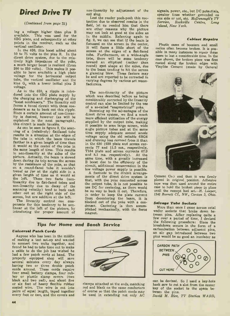
Direct Drive TV
(Continued from page 31)
ing a voltage higher than plus B available. This was used for the 6BG plate, and subsequently at other points in the receiver, such as the vertical oscillator.
In the 630, this boost added about 50 to 75 volts to the plus B. In the direct drive system, due to the rela-tively high impedance of the yoke, a much larger boost is realized (from 200 to 250 volts). This makes it pos-sible to have available a high plate voltage for the horizontal output tube, the vertical oscillator and the kine G, with a lower initial plus B voltage. As in the 630, a ripple is intro-
duced into the 6BG plate supply by the charging and discharging of the "boost condensers." The linearity coil forms a tuned circuit with these con-densers so as to buck out this ripple. Since a certain amount of non-linear-ity is desired, however (as will be explained in the next paragraph), this circuit is made tunable. As can be seen in figure 2, the scan-
ning of a (relatively) flatfaced tube results in a situation at the edges of the tube in which the beam travels farther in a given length of time than it would at the center of the tube in the same length of time. This results in non-linearity at the sides of the picture. Actually, the beam is slowed down during its trip across the screen by the resistance of the yoke, so that on a round-faced tube it wouldn't travel as far at the right side in a given length of time as it would at the left. These two facts (non-linearity due to flat-faced tubes and non-linearity due to decay of the scanning velocity) tend to buck each other out at the right side of the screen, but are additive at the left. The linearity control can com-
pensate for this tendency to be non-linear at the left of the picture, by introducing the proper amount of
non-linearity by adjustment of the coil slug.
Lest the reader pooh-pooh this con-tention due to observed results in the field, let us remind him that there are other reasons why the picture may not look at good at the sides as in the middle. Referring again to fig. 2, we can see that if the beam is focussed on the screen in the center, it will focus a little short of the screen at the edges of a flat-faced tube. Furthermore, on a wide-angle tube, there will be some tendency toward an elliptical (rather than round) spot shape at the sides, due to the beam tending to hit the screen a glancing blow. These factors may be and are reported to be corrected in varying degrees by various set manu-facturers.
The non-linearity of the picture which was described before as being considerably corrected by the linearity control can also be limited by the use of a so-called "assymetrical" yoke. Summing up the advantages of the
direct drive system, we find a much more efficient utilization of the energy supplied by the output tube, making it possible to scan large screen, wide angle picture tubes and at the same time supply adequate second anode voltage using the old reliable 6BG6 and drawing less current from it than in the 630 (630 plate and screen cur-rents 77 and 11.5 ma., respectively, T164 plate and screen currents 67.9 and 8.1 ma. respectively). At the same time, with a greatly increased B boost due to the efficiency of the circuit, additional conservation in the low voltage power supply is possible. A footnote to the circuit arrange-
ments of the direct drive system is that, with the yoke connected across the output tube, it is not possible to use DC for centering, as there would be no way to buck it out. Therefore, in order to keep the plate current from decentering the beam, it is blocked out of the yoke with a con-denser. Centering is then accom-plished mechanically, with the focus magnet.
Tips for Home and
Universal Patch Cords
Anyone who has been in the middle of making a test set-up and wanted to connect two units together, and found he had to take time out to make a cable to do the job has wished he had a few patch cords at hand. The properly equipped shop will save several minutes every day always having two or three double patch cords around. These cords require four small battery clamps, four rub-ber or plastic clamp covers (two black and two red), and about five or six feet of heavy flexible rubber coated wire. The wire is cut into pairs of equal length, taped together every foot or two, and the covers and
Bench Service
clamps attached at the ends, matching red and black on the same conductors of course so that the patch cords may be used in extending not only AC
signals, power, etc., but DC potentials, speaker lines whether grounded on one side or not, etc. McDonough's TV Service, Rockville Centre, Long Island, New York.
Cabinet Repairs
Plastic cases of boosters and small radios often become broken. It is pos-sible in many instances to repair these cases to last a considerable time. In the case shown, the broken piece was first coated along the broken edges with Vinylite Cement (made by General
Cement Co.) and then it was firmly placed in original position. Adhesive tape was then used around the entire case to hold the broken piece in place until the cement had set.—H. Leeper, 1346 Barrett Cl., NW., Canton 3, Ohio.
Salvage Tube Sockets More than once I came across octal
wafer sockets that broke down be-tween pins. After replacing quite a few over a period of time, I devised the following procedure: Since the breakdown occurs in the form of a carbonization between adjacent pins, an air gap introduced between two pins would be as good an insulator as
can be devised. So I used a key-hole hack saw to cut a slot from the center key of the socket to the space be-tween the pins. David M. Rice, TV Station WARD,
44
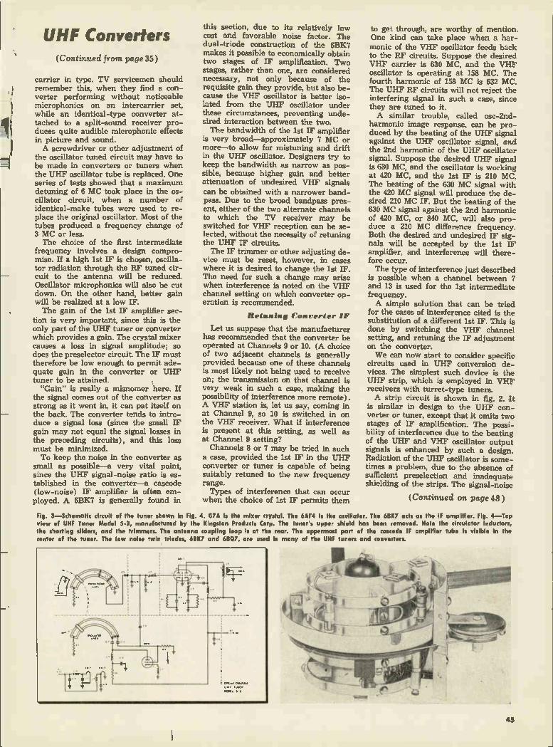
UHF Converters (Continued from page 35 )
carrier in type. TV servicemen should remember this, when they find a con-verter performing without noticeable microphonics on an intercarrier set, while an identical-type converter at-tached to a split-sound receiver pro-duces quite audible microphonic effects in picture and sound. A screwdriver or other adjustment of
the oscillator tuned circuit may have to be made in converters or tuners when the UHF oscillator tube is replaced. One series of tests showed that a maximum detuning of 6 MC took place in the os-cillator circuit, when a number of identical-make tubes were used to re-place the original oscillator. Most of the tubes produced a frequency change of 3 MC or less. The choice of the first intermediate
frequency involves a design compro-mise. If a high 1st IF is chosen, oscilla-tor radiation through the RF tuned cir-cuit to the antenna will be reduced. Oscillator microphonics will also be cut down. On the other hand, better gain will be realized at a low IF. The gain of the 1st IF amplifier sec-
tion is very important, since this is the only part of the UHF tuner or converter which provides a gain. The crystal mixer causes a loss in signal amplitude; so does the preselector circuit. The IF must therefore be low enough to permit ade-quate gain in the converter or UHF tuner to be attained. "Gain" is really a misnomer here. If
the signal comes out of the converter as strong as it went in, it can pat itself on the back. The converter tends to intro-duce a signal loss (since the small IF gain may not equal the signal losses in the preceding circuits), and this loss must be minimized. To keep the noise in the converter as
small as possible—a very vital point, since the UHF signal-noise ratio is es-tablished in the converter—a cascode (low-noise) IF amplifier is often em-ployed. A 6BK7 is generally found in
this section, due to its relatively low cost and favorable noise factor. The dual-triode construction of the 6BK7 makes it possible to economically obtain two stages of IF amplification. Two stages, rather than one, are considered necessary, not only because of the requisite gain they provide, but also be-cause the VHF oscillator is better iso-lated from the UHF oscillator under these circumstances, preventing unde-sired interaction between the two. The bandwidth of the 1st IF amplifier
is very broad—approximately 7 MC or more—to allow for mistiming and drift in the UHF oscillator. Designers try to keep the bandwidth as narrow as pos-sible, because higher gain and better attenuation of undesired VHF signals can be obtained with a narrower band-pass. Due to the broad bandpass pres-ent, either of the two alternate channels to which the TV receiver may be switched for VHF reception can be se-lected, without the necessity of retuning the UHF IF circuits. The IF trimmer or other adjusting de-
vice must be reset, however, in cases where it is desired to change the 1st IF. The need for such a change may arise when interference is noted on the VHF channel setting on which converter op-eration is recommended.
Retuning Converter IF
Let us suppose that the manufacturer has recommended that the converter be operated at Channels 9 or 10. (A choice of two adjacent channels is generally provided because one of these channels is most likely not being used to receive on; the transmission on that channel is very weak in such a case, making the possibility of interference more remote). A VHF station is, let us say, coming in at Channel 9, so 10 is switched in on the VHF receiver. What if interference is present at this setting, as well as at Channel 9 setting? Channels 8 or 7 may be tried in such
a case, provided the 1st IF in the UHF converter or tuner is capable of being suitably retuned to the new frequency range. Types of interference that can occur
when the choice of 1st IF permits them
to get through, are worthy of mention. One kind can take place when a har-monic of the VHF oscillator feeds back to the RF circuits. Suppose the desired VHF carrier is 630 MC, and the VHF oscillator is operating at 158 MC. The fourth harmonic of 158 MC is 632 MC. The UHF RF circuits will not reject the interfering signal in such a case, since they are tuned to it. A similar trouble, called osc-2nd-
harmonic image response, can be pro-duced by the beating of the UHF signal against the UHF oscillator signal, and the 2nd harmonic of the UHF oscillator signal. Suppose the desired UHF signal is 630 MC, and the oscillator is working at 420 MC, and the 1st IF is 210 MC. The beating of the 630 MC signal with the 420 MC signal will produce the de-sired 210 MC IF. But the beating of the 630 MC signal against the 2nd harmonic of 420 MC, or 840 MC, will also pro-duce a 210 MC difference frequency. Both the desired and undesired IF sig-nals will be accepted by the 1st IF amplifier, and interference will there-fore occur. The type of interference just described
is possible when a channel between 7 and 13 is used for the 1st intermediate frequency. A simple solution that can be tried
for the cases of interference cited is the substitution of a different 1st IF. This is done by switching the VHF channel setting, and retuning the IF adjustment on the converter. We can now start to consider specific
circuits used in UHF conversion de-vices. The simplest such device is the UHF strip, which is employed in VHF receivers with turret-type tuners. A strip circuit is shown in fig. 2. It
is similar in design to the UHF con-verter or tuner, except that it omits two stages of IF amplification. The possi-bility of interference due to the beating of the UHF and VHF oscillator output signals is enhanced by such a design. Radiation of the UHF oscillator is some-times a problem, due to the absence of sufficient preselection and inadequate shielding of the strips. The signal-noise
(Continued on page 48 )
Fig. 3—Schematic circuit of the tuner shown in Fig. 4. G7A is the mixer crystal. The 6AF4 is the oscillator. The 6BK7 acts as the IF amplifier. Fig. 4—Top view of UHF Tuner Model 5-3, manufactured by the Kingston Products Corp. The tuner's upper shield has been removed. Note the circulator Inductors, the shorting sliders, and the trimmers. The antenna coupling loop is at the rear. The uppermost part of the cascode IF amplifier tube is visible In the center of the tuner. The low noise twin triodes, 6BK7 and 611Q7, are used In many of the UHF tuners and converters.
43

How to Interpret AF Useful Information Can Be Obtained Without Accurate Laboratory Equip-
• It would be a great convenience if we could say that, in making service tests, one would either get the correct result or no result at all. This, unfortunately, is not the case. By making tests the wrong way, or by using the wrong equipment (or defective equipment) it is possible to produce a set of results which bear no resemblance whatsoever to the actual conditions. Or, as they say in the movies, any resemblance to actual persons living or dead is purely coincidental.
In making service tests, extreme ac-curacy is not so important, but it is
Fig. 1: Waveforms obtained with 60 cps hori-zontal input and AF oscillator on vertical, at
frequencies Indicated.
important that all the results bear more than a coincidental resemblance to what is going on in the equipment. Most servicemen learned a long time
ago that a meter with 2% accuracy is more than competent to determine the value of a resistor whose accuracy is plus or minus 20% . . . and especially when you're mostly interested in whe-ther it's shorted, open or greatly changed in value. Similarly, when read-ing DC plate and screen voltages, some-thing near the voltage on the diagram is a pretty good indication that there's no trouble in the circuit. When reading small DC voltages
(such as bias) or AC voltages (AF, RF), a VTVM is indicated, not so much for extreme accuracy as to avoid the load-ing and detuning effects which are obtained with the usual non-electronic voltmeter, even 20,000 ohms/volt, which like as not will indicate nothing at all on small voltages, especially in high resistance circuits. These effects (load-ing and detuning) have been amply covered in previous articles, and we won't bother to go into details about it here. At high frequencies, capacitance be-
comes important—in the probe, probe leads, probe connections to the circuit, etc.—and special RF probes are in-dicated. At audio frequencies, however, the writer has found that the common garden variety AC probe associated with the general run of VTVM's is quite adequate. As a matter of fact, although some
RF probes are stated to be usable over such ranges as 20 cps to 200 MC, we have found them to be quite unreliable at audio frequencies. By unreliable, we mean extremely non-linear and non-uniform. Referring back to our remarks about
accuracy, it isn't mandatory that any of your equipment be perfectly linear, but it is important that it produce the same results under the same conditions every time it is used. If it does this, you can then use it with a correction table, much in the same manner that a mariner corrects his compass readings, or a flyer his air-speed indications. But when the results are extremely
non-linear, corrections become cumber-some, and in addition, one is led to suspect that something is wrong with the equipment. Therefore, naturally, the first thing
one should do is to check the equipment which will be used for testing. This means the signal generator, the VTVM and the oscilloscope, if any. The precise frequency which the
generator puts out is not too critical as long as it covers the range you
desire, and you use the same check points every time. If you have a fairly good ear for music, you can establish check points by comparing the output of the generator (on earphones) with a known frequency and then marking the harmonics. Three standards which may be used
(and have been used by the writer) are (1) 60 cycle hum, (2) Tuning fork —one can be obtained from a music store for a dollar or less, and (3) the NBS broadcasting station WWV in Washington puts out a 440 cycle tone (A above Middle C), and so do some TV stations with their test patterns. Once you have the known standard-
60 cps, 440 cps, or whatever it may be— you can pick out by ear the octaves of this tone. Each octave above the funda-mental is double the frequency of the one preceding it (that is: 60, 120, 240, 480, 960, etc.). These are harmonics, or rather, some of the harmonics. The term "harmonic" means any multiple of the fundamental (that is: 60, 120, 180, 240, 300, 360, etc.).
It is also possible to check frequency by Lissajous figures on an oscilloscope, using 60 cycle AC on the horizontal input and the signal generator on the vertical. Above 480, however, it gets difficult to count the loops. These figures are shown in figure 1. So much for the frequency, the exact
calibration of which, as we said before, is not too important. In making ampli-tude-vs-frequency measurements with your generator, there are three things which you must consider: (1) the set-ting of the gain control, (2) the setting of the attenuator, and (3) the resistive termination across which the measure-ments are taken. Frequency response and purity of the
sine wave output may be affected by the setting of the gain control. On high quality equipment this need not be so, but it's a good idea not to take it for granted without checking. The same thing may be true of the attenuator setting, and the resistive termination. The latter is the first thing which must
be attended to before making any tests. Every generator works most efficiently and effectively when properly termi-nated in a load equivalent to its internal impedance. The output voltage will, of course, increase with increased load resistance up to a certain point. The open circuit voltage of a generator (or an amplifier) may not correlate at all with the output across the proper load with respect to amplitude, linearity and distortion, so this must always be at-tended to. When testing a power ampli-fier, the load resistor which is substi-tuted for a voice coil must also be of
46

Response Measurements ment But Care Must Be Exercised in Making Tests and Analyzing Results
AUDIO RESPONSE CHECK POINTS Signal Generator: Is it properly terminated; is it linear
at all settings of gain control; is it linear at all set-tings of attenuator; is it properly matched to the unit under test; is there hum or harmonics in output?
VTVM: Is the response of the voltmeter and its probe linear over the audio range?
Amplifier: Is proper input being applied to it (no over-loading); is it properly loaded on the output side; is there hum or harmonics in output?
adequate wattage to accommodate the output of the amplifier.
If the signal generator does not have an output attenuator (and many of the less expensive ones do not), the tech-nician would do well to install one if he intends to make useful employment of the unit. The reason for this is one of the cardinal points of testing of this type, namely that the input voltage to the unit under test should be proper for its design. If the unit under test is overloaded, the results may be abso-lutely meaningless. An example of this is a preamp for a
magnetic pickup—or for that matter, any low level input stage. The output of a GE magnetic pickup is about 10 millivolts and the input to the preamp is therefore of that order. Where the output of the signal generator may be anywhere from a volt to 10 volts, the preamp is obviously extremely over-loaded. That is to say, with the bias set for small input voltages, the tube will in effect operate with insufficient bias, and saturation, clipping and distortion (production of harmonics, among other things) will occur. You can easily observe this by observing the output of such a stage on a scope. With exces-
Fig. 2: B, C, D show distortion of sine wave in-
put (A) with too large an Input signal. In the extreme (D), squaring of the wave results.— Illustrations from "Encyclopedia on Cathode Ray Oscilloscopes and Their Uses," published by John F. Rider.
sively high input voltages, the output waveform becomes an almost perfect square wave (see fig. 2). Which fact brings us to the genera-
tor's gain control setting. In the first place, it may not be possible to reduce the gain sufficiently with the gain con-trol (in the absence of an attenuator, that is). In the second place, the genera-tor may not operate satisfactorily at very low settings of the control. As an example, the writer one time
made a frequency run on an amplifier with a very low gain control setting of the generator. The results obtained were so linear that they were suspect, since the amplifier had compensation circuits which would have precluded such results. The tests were then re-peated with an oscilloscope and it was discovered that all the signal genera-tor was putting out at this setting was 60 cycle hum, and therefore the entire "frequency run" was actually done at a single frequency. The output attenuator, of course, must
also be checked at different settings, as mentioned earlier, since such devices are usually frequency sensitive. This is especially true if the attenuator is only a "volume control" type unit. Such a unit reflects different impedances at dif-ferent settings, and also varying dis-tributed capacitance due to the wiring. A constant impedance T-pad is a better solution. Not only should the generator be
properly terminated, but also the input impedance of the device under test should be properly matched. To connect a low impedance device across a high impedance generator will seriously affect the operation of the generator. To merely mismatch the output of the generator will, of course, affect its out-put voltage. Several frequency runs on the gen-
erator itself, at different gain settings and different attenuator settings, while tedious, will clear the atmosphere for
all future work. The technician will either find that the output of the gen-erator is linear to a useful degree over the main part of its ranges, or else he will find out what allowances must be made for non-linearities in future tests. There is yet one big "except" to the
foregoing statement, which is that the results depend on the reliability of the VTVM. It is highly desirable that some comparative tests be made in order to establish the validity of the VTVM readings. For instance, the same tests can be made with some other meter; or the meter can be tested on some other generator; or the observed readings on the VTVM can be compared with visual results on a scope. Any two sets of
Fig. 3: Arrangement for estimating both fre-quency and amplitude distortion at a glance,
making It easy to monitor oscillator output for uniform input to the device under test.
readings which were close to being the same would put the technician's mind at rest on this score. The usefulness of an oscilloscope for
audio testing cannot be overemphasized, for the scope reveals distortion and amplitude at the same moment. As men-tioned before, it is practically impossible to tell whether (for instance) the volt-age on a meter contains a lot of 60 cycle hum, or whether it contains har-monics, etc. In this respect, the writer recalls a frequency run on a 3 or 4-year-old tape recorder. Fairly good (voltage) output was observed to 10,000 cycles, but when the results were observed by listening to the tape, it was found that above 6000 there was nothing but a wild jumble of whistles and birdies which resulted from intermodu-lation between the signal input and the bias, which was in that case 20 KC. In
(Continued on page48 )
47

Audio Response Shop Shortcuts (Continued from page 47 )
addition, there was some hum. The oscilloscope has a very critical
eye for such details, on the other hand. When reading amplitude of the trace, it should be remembered, of course, that the trace is a peak-to-peak indication which is 2.83 times RMS readings obtained on the VTVM. It should also be borne in mind that the average VTVM does not respond accurately to non-sinusoidal waveforms, whereas the scope gives a complete picture (depend-ing of course, on its own accuracy) of whatever is put into it. The scope will thus detect distortion in the output of the signal generator as well as distor-tion introduced by the amplifier under test. The scope can also be used for square-
wave testing, of course, which is a terrific shortcut in audio amplifier checking, since it coLers amplitude, frequency and phase all at one time over a fairly wide range.
UHF Converters (Continued from page 45)
ratio for incoming UHF signals may be much poorer (than in UHF converters or tuners). UHF oscillator frequency drift has been observed to be greater, due to lack of suitable drift-compensat-ing units.
There are two strip sections in each UHF strip. One section is made up of the antenna input circuit, a crystal mixer with its tuned circuit, and a 1st IF grid coil. The other strip section contains coils for the 1st IF plate, converter grid and oscillator. (The stages referred to are the VHF receiver's RF amplifier, converter and oscillator, respectively.) An oscillator harmonic generator crystal and its accompanying bias network is also present. The oscillator crystal generates a
fundamental frequency, a harmonic of which is used as the oscillator signal. The UHF signal is fed into the balanced antenna input coil and transformer-coupled into the mixer tuned circuit, where it is mixed with the oscillator signal, causing an IF signal to be pro-duced. This 1st IF signal falls into the section of the spectrum that lies be-tween the low and high VHF bands. The 1st IF is coupled to the VHF re-
ceiver's RF amplifier, and then proc-essed like a conventional VHF signal. UHF strip circuits have been consid-
erably improved of late, but the circuits employed are, at the time of writing, not available. One strip manufacturer dispenses with a dual conversion sys-tem, and converts the UHF signal di-rectly into a 40 MC video IF signal. By switching in suitable tuned circuits, he is enabled to use the VHF oscillator and mixer to amplify the UHF signals.
Universal Test Cord
One of the most useful tools around any repair shop is a test cord for the AC supply line. This test cord has fused plug on one end which car-ries two tubular fuses of 2 to 6 amp, capacity, depending on the equipment to be under test. On the other end it has small alligator clips almost completely covered by rubber
grips to protect the technician from shock and to keep the clips separated when they are used on terminals which are close to each other. This sort of cord can be used as a universal test cord for TV sets, particularly in the case of older sets such as GE, Philco, Emerson, which for some years had an AC interlock receptacle dif-fering from what has now become standard for the industry.—Arthur Bertram, 247 West 13th St., New York, N. Y.
Test Lamp Setup
Useful in testing for shorts in radios and other devices, but particularly needed when checking for shorted
power-supply components, this fuse protector lights up brightly on shorts, dully if device is OK. J. L. Brody, Ab's Radio, Chapel Hill, N. C.
Tool Keeper
Although you may have "a place for everything" in the way of tools at your service bench, it is very seldom that you keep "everything in its place" when you're busy turning out the work. The result is that when you want a particu-lar tool, you have to stop and turn everything over in an attempt to find it. I have solved this problem by putting the most-often-used ones in a pan or tray where I have them handy for every job. I use a wide bread pan, which
•
works out very nicely. For the contents, I suggest: long nose pliers, cutters, solder, soldering tool, dual blade screw-driver (Philips & Standard), small set- P' screw driver, 1/4" socket, %" socket and flashlight—Ralph E. Hahn, 2450 Wauke-pan Rd., Glenview, Ill.
Dial Stringing I use an old shoe-button hook to pick
up cable and slide it onto reels. For string, I use 24 lb. hard braided nylon fishing line, which I find most satisfac-tory. Some wax on a large pulley will help hold two cables in place while stringing. To get a good fit, I first string the cable on the shafts of the slide pul-leys (will stay in place there better, too) and when I'm finished, I slip it over the pulleys themselves. This makes the cable tight and eliminates "push-pull" dialing. Rubber bands on knob shafts keep string from slipping.—Beryl Bass, Bass Radio, Lamoni, Iowa.
Intermittent Noises Don't bother to examine the TV set
or radio in cases where the customer says that walking across the floor causes noise in the receiver. The trouble is in the house wiring, and may be due to grounded electrical feed wires, or lack of a ground for the entire lighting circuit. In some cases it is possible to eliminate the "noise" condition by mov-ing the receiver to another location.
Servicers "Third Hand"
Often on midget radios, it is impos-sible to make the usual mechanical joint first, before soldering, due to short leads or very tight quarters.
The drawing shows how I use a spring clip as a third hand to hold the solder in exactly the right po-sition.—J. Amorose, Amorose Radio, Route 4, Hungary Rd., Richmond, Va.
Phone Groove-Skipping Before making any adjustments on a
phono record changer where the com-plaint concerns the arm "sliding" across the microgroove record, use a small pocket level to determine whether or not the turntable is tilted. Sometimes it is necessary to raise the rear of the turntable slightly to eliminate "sliding," though, theoretically, it should be per-fectly level.—Ed. Note: Obviously you should do this before removing the changer from console or table cabinet, in the customer's home.
N-RI-2 PRINTED IN U.S.A.


RADIO & TELEVISION DATA for
RADIOTRICIANS* & TELETRICIANS*
'Registered U.S. Patent Office,
Prepared as a Service
Especially for Members of the
NATIONAL RADIO INSTITUTE ALUMNI ASSOCIATION
Washington 9, D. C.
Compiled by John H. Battison,
Director of Education, National Radio Institute
Reprinted from
TELE-TECH and RADIO & TELEVISION RETAILING
Copyrighted (all rights reserved) by
CALDWELL-CLEMENTS, INC.
480 Lexington Ave.
New York 17, N.Y.

TV Receiver Manufacturers Ready Set makers show FCC and industry engineers various means for adapting
WHILE at Washington the.. engi-neers of the FCC and the broad-
cast stations work to set up a UHF TV allocation (see large chart accom-panying this issue of TELE-TECH), the manufacturers of TV sets also have been busy designing conver-sion devices which will permit pres-ent VHF standard TV sets to receive stations in the UHF band.
And although a year or two may elapse before UHF-TV becomes a matter of actual general operation in the United States, the manufac-turers well recognize that TV sets going on the market this Fall will be expected to serve their owners for a number of years and so must be simply convertible to receive UHF signals when these do come on the air in 1952, '53 or '54!
Bridgeport Tests
Progress in UHF conversion of standard TV receivers of many makes was high-lighted several weeks ago when the RTMA invited the FCC members and engineers to a demonstration of UHF adapters, held at Bridgeport, Conn., where NBC has an experimental UHF transmitting station in regular oper-ation.
CROSLEY—"Ultra tuner" measures 7 x 7 x 91/2 in.; attached by screwdriver to re-ceiver. Works with any continuous-tun-ing TV receiver. One model Ultratuner with self-contained UHF antenna. Instal-lation requires no work on receiver. Cov-ers 122 to 132 megacycle freque-icy range. Retail price, about $40.
CAPEHART-FARNSWORTH—Using a reg-ular Capehart CX-33 receiver chassis, four miles from the Bridgeport transmitter ultra-high-frequency conversion was ac-complished by inserting UHF channel strips in Standard Coil tuner already a part of instrument. Complete Capehart line uses same chassis.
The TV receiver makers had set up their conversion devices in the bedrooms of Bridgeport hotels, about 4 miles from the transmitter, and the Washington officials trooped from room to room, watching the clear, bright UHF pictures received on 529-535 megacycles at 4 miles distance, and comparing these with the same program—snowy and dia-
GENERAL ELECTRIC — This Translator (Model UHF-101) has been tested for 18 months in the Bridgeport area and is now in limited production. Below the mega-cycle numerals there is a logging scale for added convenience in tuning. A travelling dial light spot-illuminates each numeral.
thermy-ridden—received on VHF channel 4 from New York, 56 miles away.
In this respect, the Bridgeport demonstrations proved almost too convincingly that UHF gives superior results without reception difficulties. For as the manufacturers' experi-mental engineers vied with each other to bring in perfect UHF re-ception in the lofty hotel rooms, the non-technical observers did not al-ways stop to think what correspond-ing quality of UHF reception would be possible in the homes of an aver-age city or town with hills and build-ing obstructions.
Downlead Problems
Difficulties of carrying UHF sig-nals many feet from antenna to chassis were also apparent. One maker had installed a roof-top an-tenna 25 ft. away but experienced such losses in the down-lead, that a built-in antenna in his converter box gave practically the same effec-tive signal! The tiny UHF antennas of pencil length, however, showed the simplicity of the UH4F pick-up problem for direct-view locations. Some UHF antennas were simply stuck up on the wall with adhesive.
HALLICRAFTERS' new ultra-high-fre-quency converter operates over a 450- to 900-megacycle range. The output fre-quency feeds into either Channel 3 or 4 of any present-day television receiver. The Hallicralters Company also has UHF coil strips available for its turret-type "Dynamic Tuners."
2

with UHF Conversion Devices present standard VHF sets to receive programs from future UHF stations.
STROMBERG-CARLSON'S converter. styled in green leatherette and measur-ing only 8 x 4 x 6 in., uses a 6F4 as a local oscillator, a 6BQ7 as a cascode r-f preamplifier, and a 1N72 germanium crys-tal mixer. Unit has a 12MC bandwidth and balanced output feeds VHF-TV chan-nels 5 or 6.
To the lay Commissioners, the novel converter container shown by Stromberg-Carlson in the form of a handsome tooled-leather cigar box, attracted special attention, and pointed a possible trend of decora-tive camouflaging which purchasers may demand, if UHF converters are to be kept on top of their present TV receivers in their living rooms.
Pictured herewith are a number of UHF converters or translators which have been developed by TV
STANDARD COIL—Simple transfer of strips in tuner, readies any set so equipped, for reception of uhf signals within a few minutes. The two-section strips in effect turn TV set into a double conversion circuit. CK 710 diode is used as converter. Fingers shown belong to Edwin Thias. engineering VP.
manufacturers for their own receiv-ers or for general use with all or most receivers. Included also are several designs which were not dem-onstrated at the RTMA-FCC Bridge-port session.
Other Exhibits
In the case of certain converting devices exhibited at Bridgeport, photographs were not released but information as follows was made public at the individual session:
PHILCO—While this company has been experimenting with several types of UHF conversions, it dem-onstrated at Bridgeport only an ex-ternal converter with continuous tuning which may be attached to any Philco TV set. This covers the full range of proposed UHF chan-nels and is easily attached. Philco also has its tiny "match-box" single-channel converters which may be made available later, for use under appropriate conditions.
RCA VICTOR—Designed to bring in all UHF channels and suitable for attachment to any television re-ceiver, the RCA converter was shown to give pictures that compare
TARZIAN—Full-band UT-1 tuning unit for ultra-high-frequency telecasts is adapt-able to any set now in use; does not interfere with VHF channels. Self-con-tained power supply. No electrical changes are necessary in present tele-vision sets. Unit may be placed on top of the set or installed inside.
ZENITH—During the FCC Bridgeport demonstrations, Zenith engineers showed how a UHF strip (like that pictured) could be slipped into the Zenith tuner in a very few minutes, enabling the standard receiver to operate on UHF without any change in the set itself
favorably in every respect with VHF reception. On the face of the attrac-tively designed converter are two knobs and an easily read dial. Instal-lation of the converter is sufficiently simple to be performed from an in-struction sheet by the average set owner. Retail price, about $50.
MALLORY—Means for convert-ing standard television receivers were demonstrated at the Stratfield Hotel, Bridgeport, and inspected by the FCC party, but photographs and technical details requested by TELE-TECH were not available at press-time.
WESTINGHOUSE—With this new UHF converter, the set is capable of receiving all uhf channels, in addition to standard telecasts in the very-high-frequency range. The converter, housed in a ma-hogany finished wood cabinet, can be easily connected to all Westinghouse television receivers now in use.
3

Receiving Antennas Three-year field tests near Washington, D. C.
for UHF operation on basis of electrical
By E. O. JOHNSON and J. D. CALLAGHAN
Radio Corporation of America,
Camden, N. J.
REQUIREMENTS for the recep-tion of television signals on the
UHF band (470 - 890 MC) are much the same in many respects as on the existing VHF band (54 - 216 MC). For the more difficult fringe areas, or locations where reflections are severe, special types of antennas will be needed, just as they are in VHF. Of the wide variety of special
UHF antennas designed and tested during field tests in Washington and
Stratford, near Bridgeport, Conn., from 1948 to the present, several types have proved so outstanding in their simplicity, economy, and per-formance, that it is felt they will find additional widespread use where maximum performance and reliabil-ity are primary considerations. Each of these special types pos-
sesses properties peculiar to its in-dividual design, and these types should provide a choice that will
meet the requirements of even the most difficult locations. While the factors of performance,
size, ease of installation, appearance, strength, cost, and availability of materials must all be considered in UHF antenna design, this discussion will be limited to performance, as determined by the electrical charac-teristics. Antenna characteristics are classi-
fied here according to gain, directiv-ity, and bandwidth, as follows: Gain—Antennas may be roughly
classed as "low gain" or "high gain," depending on their design for use in strong signal areas or weak signal areas. It should be noted that in all
Fig. 4: Fan dipole
FAN DIPOLE
FREQ.- MC
Fig. 5: Fan dipole gain
Figs. 1-3: (Left) Diagrams showing (above) horizontal field patterns for Channel 2 dipole and reflector, (center) VHF f an-type dipole and reflector, (bottom) VHF double V antenna
Fig. 6: Horizontal field pattern showing directivity of fan dipole
100 •/.. - RELATIVE VOLTAGE RESPONSE - 100
eiseer*, owe ff4, ere e
aiat•, ,etti
WA'e*** • «qv • d • 4eae• 55011C
HORIZONTAL FIELD PATTERN
otie. Aterrise,Ist immieweeeem, *lee e • 4tie ewe,. ens
RSO NC
4

for UHF Television and Bridgeport, Conn. reveal antenna types best suited
performance, mechanical simplicity, and cost economy
the gain curves shown, the 0 db ref-erence line is the gain of a thin half-wave dipole adjusted to resonance at each individual frequency. Thus, any given point on the gain curve refer-ences the antenna under discussion back to a half-wave-length dipole resonated for that particular fre-quency. The antennas shown have been designed to work into a bal-anced 300-ohm line, the gain curves were obtained by using a 300-ohm load at the antenna, and the refer-ence dipole was also matched into 300 ohms.
Directivity—This can vary from the low-gain omni-directional an-tenna, which receives from all direc-tions, to the highly specialized uni-directional antenna, which has a very narrow angle of reception from one direction only, thus discriminating against unwanted signals. Direc-tivity can be further broken down into horizontal and vertical planes. Horizontal directivity can often be used to great advantage in reducing reflections and multi-path cancella-tion of signal from objects in direc-tions other than that of the trans-mitting station. Vertical directivity is often very useful in removing the effects of signal cancellation due to reflection from the earth or other objects either above or below the path between the receiving antenna and the transmitter. This also makes
12
10
z 6
4
2
o
2 STACKED FAN DIPOLES
00 600 600 800 FR EQ. MC
00
co o
12
10
9
8
7
6
z 5
0 4
3
2
o
4 STACKED FAN DIPOLES
500 600 700 800
FREQ. MC 900
Figs. 7-10: (Left) Physical appearance of two-stacked (left) and four stacked fan dipoles. (Above) Gain vs frequency for the two types
the placement of the antenna less critical. Flutter of signal caused by airplanes is often substantially re-duced by an antenna with high verti-cal directivity. Since high directivity and high gain usually go hand in hand, the so-called "fringe area" type of antenna is very useful in metropolitan areas to eliminate re-flections or multi-path conditions. Bandwidth—Antennas may also be
classified as to their bandwidth, i.e., their ability to receive signals ef-ficiently over a wide range of fre-quencies. Since the UHF spectrum covers 70 television channels, the de-sign of these antennas sometimes seems unconventional when compared to the usual type of antenna de-signed for single-channel operation.
VHF Antennas at UHF
Most VHF antennas are not very satisfactory at UHF, except in me-dium and high signal strength areas which are free from reflection prob-lems. Their general UHF character-istics are: Gain—Low, varying from approxi-
mately 10 db below a resonant dipole to 3 db above that of a resonant di-pole when they are oriented for maximum response.
Directivity—Poor in both the horizontal and vertical planes. This is due to the many lobes present
and the fact that the major lobe does not usually fall on the axis of the antenna. Figs. 1, 2, and 3 show the horizontal polar patterns of three widely used types of VHF antennas at 550 and 850 MC.
These, as well as other polar pat-terns in this article, are shown in terms of relative voltage with the maximum lobe being equal to 100%. Because the television receiver is es-sentially a voltage-sensitive device, signals picked up by any of the minor lobes will appear on the receiver in the same relation as shown on the chart. Polar patterns are sometimes shown in terms of power, which will make the same antenna appear to be more directive. Thus, a minor lobe showing only 10% response in a power plot, will actually be 31.6% in voltage. Bandwidth—This is generally ade-
quate, with the gain falling off some-what toward the high end of the band. A major disadvantage is that the main lobes shift direction with frequency, requiring separate orien-tation for stations operating on widely separated channels.
Fan Dipole
This dipole, shown in Fig. 4, is one of the simplest of all UHF an-tennas. The antenna is constructed of two triangles of metal, supported
5

RECEIVING ANTENNAS FOR UHF TV
Figs. 11-13: Physical
12
lO II
8
0 7 Z
.7( 5 o
RHOM B IC
4
3
2
O 600 700 800 900
F RE() MC
appearance, gain vs frequency curve, and horizontal field pattern directivity for rhombic antenna
STACKED • V"
FRE0 - C
Figs. 14-16: Physical appearance, gain vs frequency curve, and horizontal field pattern directivity for stacked "V" antenna
by a suitable insulator. Both trian-gles lie in the same plane, and the transmission line is attached to each apex. Its characteristics are as fol-lows: Gain—The gain is shown in Fig.
5. It will be noted that this antenna shows some g*ain over a half-wave dipole because of its unique con-struction.
Directivity — Typical directivity patterns are shown in Fig. 6. While a slight front-to-back ratio seems unusual for a dipole antenna, the re-duction in response in one direction is caused by the metal mast and mounting support. Bandwidth—As can be seen from
Fig. 5, the bandwidth of the trian-gular shaped dipoles is excellent.
Stacked Fan Dipoles
The simple fan dipole can be stacked vertically, as shown in Figs. 7 and 8. When properly phased, the gain of the two-stack fan dipole is that shown in Fig. 9, and that of the four-stack fan dipole is that shown in Fig. 10.
This stacking will result in an in-crease of vetrical directivity, al-though the horizontal directivity will remain as shown in Fig. 6.
It will be noted that the bandwidth, while still good, is not quite as uni-form as that of the single fan dipole. This is mainly due to some frequency selectivity in the individual trans-mission lines used for phasing the dipoles.
Rhombic Antenna
Rhombic antennas have been built and used very successfully during all the UHF field tests. One of these is illustrated in Fig. 11. These rhom-bics have been adjusted for uni-directional operation and are usually terminated at the far end with a suitable resistor. The general char-acteristics are as follows:
Gain—High, as shown in Fig. 12, making this antenna very well suited for fringe area operation.
Directivity—This is also very good, as shown in Fig. 13. It will be noted that the major forward lobe is quite narrow in the horizontal direction, decreasing in width with increasing frequency. While some minor side and back lobes are present, these should give no trouble except in very severe cases of reflections or multi-path reception. Although the verti-cal directivity pattern is not shown,
the major lobe in the vertical direc-tion is approximately three times as broad as that shown for the hori-zontal. Bandwidth—This is a broad-band
type of antenna, showing a rising gain characteristic toward the high-frequency end of the band, which is very desirable.
Stacked Rhombics
Two or more of these rhombics can be stacked vertically, one above the other. When two of these an-tennas are stacked 12 inches apart, the result is an increase in gain of about 2 db across the entire band.
This stacking also increases the vertical directivity, although the horizontal directivity will remain ap-proximately as shown in Fig. 13.
Stacked "V"
Two "V" type antennas stacked one above the other are illustrated in Fig. 14. This combination uses the same rods as a standard dipole made for Channel 2, and thus con-tains about the same amount of metal as a simple VHF dipole and reflector. It is a very efficient an-tenna, considering its simplicity of
6

CORNER REFLECTOR
00 900 F RECL-NC
Figs. 17-20: Sheet reflector-type antennas (1. to r.) Flat sheet, parabolic reflector, and corner reflector with gain vs. frequency curve
Fig. 21: (Left) Horizontal directivity field pattern for corner reflector. Fig. 22: Vertical directivity field pattern for corner reflector
construction, and is relatively easy to mount on existing masts. It shows the following characteristics: Gain—This is a relatively high-
gain antenna (as shown in Fig. 15) for use in medium and weak signal areas. It also shows an increasing gain characteristic with frequency, which is highly desirable to over-come both propagation and transmis-sion line losses which increase with frequency. Directivity—The directivity pat-
tern, as shown in Fig. 16, indicates one narrow major lobe, plus multi-ple secondary lobes. This should be adequate in most areas that are rea-sonably free of reflections. Bandwidth—The bandwidth of this
antenna is excellent, covering more than the required frequency spec-trum.
Sheet Reflector Types
Sheet reflector-type antennas, wherein one or more dipoles are ar-ranged in front of a large metallic sheet, have been in use for some time in such applications as radar and micro-wave transmission. Although they can take many
forms, three experimental types are shown here, Fig. 17 showing dipoles arranged ahead of a flat sheet; Fig.
12 6 ELEMENT VAGI
FREQ.-MC
Figs. 23-25: (Left) UHF Yagi, (center)
gain vs frequency for 6 element Yagi, (right) horizontal field pattern for latter
Fig. 26: (Left) Helical antenna. Fig. 27 (Center) Stacked dipoles and reflectors Fig. 28: (Right) Slot type antennas may be used extensively on UHF-TV
1 7

UHF ANTENNAS
18 showing five co-linear dipoles at the focus of a parabolic sheet; and Fig. 19 showing a modified fan di-pole of a corner reflector. While the ideal reflector is a solid
sheet of metal, a multiple number of rods or a wire mesh is generally used to reduce wind resistance, ice load-ing, and weight. This is perfectly satisfactory from an electrical stand-point, provided that the openings in the metal are only a small fraction of a wave length.
Being one of the most compact and highly efficient of the sheet reflector types, the corner reflector has been selected for discussion here. This particular antenna uses a 90° in-cluded angle in the corner and a modified type of fan dipole as the antenna element. It will be noted in Fig. 19 that the fan dipole is also folded at 90° to conform to the shape of the reflector. Following are its characteristics: Gain—This antenna has the ulti-
mate in gain for its compact size, as shown by Fig. 20. It should be one of the best performers in fringe areas.
Directivity—This antenna is also an outstanding performer in direc-tivity, being truly uni-directional. The directivity in the horizontal plane is shown in Fig. 21, and the directivity in the vertical plane in Fig. 22. The almost complete ab-sence of unwanted lobes should re-duce reflection and multi-path trou-bles to an absolute minimum. Bandwidth—Although the corner
reflector antenna is normally consid-ered to be a relatively narrow-band-width antenna, the combination of a proper-size reflector and the unique design of the dipole element has re-sulted in a compact, high-gain an-tenna which covers the entire UHF spectrum.
Yagi Antennas
The Yagi is a familiar type of high-gain, narrow-bandwidth array which can be equally as useful at UHF as at other frequencies. It produces more gain for its size and weight than any other types of an-tenna. The mechanical construction of a yagi to operate at these fre-quencies is very critical, and close dimensional tolerances must be held if its high gain is to be realized. The one illustrated here (Fig. 23) is a six-elemert, wide-spaced type. At UHF, advantage can be taken of the increased gain afforded by wide spac-ing without a structure which is pro-hibitive in size. The antenna shown
here has an over-all length of only 28 inches. Gain—The gain curve is shown in
Fig. 24. While this should be ade-quate for most weak signal installa-tions, still higher gains may be ob-tained by stacking two or more of these antennas in the conventional manner.
Directivity — The horizontal di-rectivity pattern of this antenna is shown at its resonant frequency in Fig. 25. This is also a very excellent pattern for the elimination of reflec-tions and unwanted signals. The vertical directivity pattern shows only a slightly greater lobe width than the horizontal pattern. Bandwidth—This is a very narrow
bandwidth antenna, showing its peak gain only on the channel for which it is made. It may be noted, however, that a total of seven UHF channels fall within the range of this antenna it a sacrifice in gain of 3 db at either end of the pass band can be tol-erated. Almost any type of antenna used
at other frequencies can be designed for operation on the UHF television band. Simple types, such ordinary dipoles, dipoles and reflectors, and combinations of these can be used effectively, although they will not show the broad bandwidth charac-teristics of the previously described special types. One such array of di-poles and reflectors is shown in Fig. 27.
Also worthy of mentioning are several experimental types which are too cumbersome to use at lower fre-quencies, but adapt themselves very readily in this portion of the spec-trum. They are the helical-type an-tenna, shown in Fig. 26, and the slot-type antenna, shown in Fig. 28.
Transmission lines are an impor-tant part of the receiving antenna system, and many types of lines have been evaluated during the field tests. The best antenna performance can be obtained only by the proper choice and installation of the transmission line. Because of the much greater loss in the flat ribbon types of trans-mission line under adverse weather conditions, those used with the most success in experimental UHF instal-lation have been Types 2, 3, and 4, in the list below. The 300-ohm tubu-lar line, while better than the flat line under conditions of soot, grime, and moisture, still shows an appreci-able increase in loss. The coaxial types are not affected, but naturally have greater initial attenuation. The proper choice of transmission line and its proper installation will pro-vide the same trouble-free service as that obtained on present VHF chan-nels.
Type 1 Standard 300. Ohm Flat Line
2 Tubular 300-Ohm Line 1.1 2.5 3.0 6.8 4.6 10.0
3 PG 59/U Coax 3.7 — 9.6 — 14.5 — 4 PG 11/U Coax
Loss — DB/100 Feet 100 MC 500 MC 1,000 MC Dry Wet Dry Wet Dry Wet
1.2 7.3 3.2 20.0 5.0 30.0
1.9 — 5.2 — 7.8 --
The antennas discussed above are all of the balanced 300-ohm type. Where it is found desirable to use an unbalanced 75-ohm coaxial transmis-sion line, or where the receiver is designed for 75-ohm unbalanced in-put, an impedance transformer and balancing network are necessary to couple these two unlike items to-gether. This balancing network is referred to as a balun, and the im-pedance transformer can be conven-iently incorporated in the same structure. A lightning arrestor is often
necessary on UHF as well as on VHF. Lightning arrestors designed for VHF use have proven unsatis-factory at UHF, due to their elec-trical mismatch and signal loss. The balun incorporates positive lightning protection in its design, without the
rig. 29: Balun for matching balanced 300-ohm line to unbalanced 75-ohm coaxial
losses of standard lightning arres-tors, provided its case is adequately grounded.
Typical installation procedure when using 300-ohm line is to install the balun (shown in Fig. 29) on the outside of the building near the en-trance point of the transmission line, and to attach a lightning ground to its case. Coaxial line is then run to the 76-ohm input of the receiver.
If coaxial line is used throughout, the balun is installed at the antenna and the shield of the coaxial cable is properly grounded at the entrance to the building.
Naturally, it will be to everyone's advantage to make UHF installa-tions as simple and economical as possible. The approach in adding UHF to present VHF may be to utilize one of the following pro-cedures:
a. Investigate the possibility of using the existing VHF an-tenna and transmission line— compromising antenna orienta-tion where necessary.
(Continued on page 41 )
8
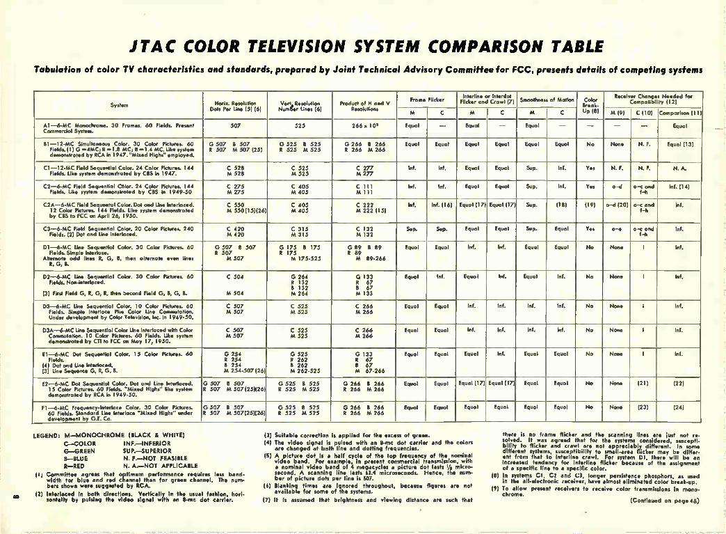
JTAC COLOR TELEVISION SYSTEM COMPARISON TABLE Tabulation of color TV characteristics and standards, prepared by Joint Technical Advisory Committee for FCC, presents details of competing systems
System Horiz. Resolution Dots Per Per Line (5) (6)
Vert„ Resolution Numger Lines (6)
Product of H and V Resolutions
Frame Flicker Interline or lnterdot
Flicker and Crawl (7) Smoothness of Motion Color Receiver Change Needed for
Compatibil ty (12)
M C M C M (9) C (10) Comparison II I) M C UP (8)
A1-6-MC Monochrome. 30 Frames. 60 Fields. Present 507 525 266 x 10, Equal — Equal — Equal — — — — Equal Commercial System.
81-12-MC Simultaneous Color. 30 Color Pictures. 60 G 507 B 507 G 525 B 525 G 266 B 266 Equal Equal Equal Equal Equal Equal No None N. F. Equal (13) Fields. (1) G =4MC; R =1.8 MC; B =1.4 MC. Like system demonstrated by RCA in 1947. "Mixed Highs employed.
R 507 M 507 (25) R 525 M 525 R 266 M 266
Cl —12-MC Field Sequential Color. 24 Color Pictures. 144 C 528 C 525 C 277 Inf. Inf. Equal Equal Sup. Inf. Yes N. F. N. F. N. A. Fields. Like system demonstrated by CBS in 1947. M 528 M 525 M 277
C2-6-MC Field Sequential Cblor. 24 Color Pictures. 144 C 275 C 405 C Ill Inf. Inf. Equal Equal Sup. Inf. Yes a-d a-c and Inf. (14) Fields. Like system demonstrated by CBS in 1949-50 M 275 M 405 M 111 f-h
-- — C2A-6-MC Field Sequentol Color. Dot and Line Interlaced. C 550 C 405 C 222 Inf. Inf. (16) Equal (17) Equal (17) Sup. (18) (19) a-d (20) a-c and Inf.
12 Color Pictures. 144 Fields. Like system demonstrated by CBS to FCC on April 26, 1950.
M 550(15)(26) M 405 M 222 (15) f-h
C3-6-MC Field Sequential Color. 20 Color Pictures. 240 C 420 C 315 C 132 Sup. Sup. Equal Equal Sup. Equal Yes a-e a-c and Inf. Fields. (2) Dot and Line Interlaced. M 420 M 315 M 132 f-h
D1-6-MC Line Sequential Color. 30 Color Pictures. 60 G 507 13 507 G 175 8 175 G 89 B 89 Equal Equal Inf. Inf. Equal Equal No None i Inf. Fields. Simple Interlace. R 507 R 175 R 89
Alternate odd lines R, G. B, then alternate even lines M 507 M 175-525 M 89-266 R, G, B.
D2-6-MC Line Sequential Color. 30 Color Pictures. 60 C 504 G 264 G 133 Equal Inf. Equal Inf. Equal Inf. No None I Inf. Fields. Non-interlaced. R 132 R 67
8 132 8 67 (3) First Field G, R, G, R, then Second Field G, 8, G, B. M 504 M 264 M 133
D3-6-MC Une Sequential Color. 10 Color Pictures. 60 C 507 C 525 C 266 Equal Equal Inf. Inf. Inf. Inf. No None i Inf. Fields. Simple Interlace Plus Color Line Commutation. M 507 M 525 M 266 Under development by Color Television, Inc. in 1949-50.
D3A-6-MC Line Sequential Color Une Interlaced with Color C 507 C 525 C 266 Equal Equal Inf. Inf. Inf. Inf. No None 1 Inf. Commutation. 10 Color Pictures. 60 Fields. Like system demonstrated by Cil to FCC on May 17, 1950.
M 507 M 525 M 266
El —6-MC Dot Sequential Color. 15 Color Pictures. 60 G 254 G 525 G 133 Equal Equal Equal Inf. Equal Equal No None 1 Inf. Fields. R 254 R 262 R 67
(4) Dot and Line Interlaced. 8 254 B 262 B 67 (3) Line Sequence G, R, G, B. M 254-507 (26) M 262-525 M 67-266
E2-6-MC Dot Sequential Color. Dot and Line Interlaced. G 507 B 507 G 525 B 525 G 266 8 266 Equal Equal Equal (17) Equal (17) Equal Equal No None (21) (22) 15 Color Pictures. 60 Fields. "Mixed Highs" like system demonstrated by RCA in 1949-50.
R 507 M 507(25)(26) R 525 M 525 R 266 M 266
Fl —6-MC Frequency-Interlace Color. 30 Color Pictures. G 507 8 507 G 525 B 525 G 266 B 266 Equal Equal Equal Equal Equal Equal No None (23) (24) 60 Fields. Standard Line Interlace "Mixed Highs" under development by G.E. Co.
R 507 M 507(25)(26) R 525 M 525 R 266 M 266
CO
LEGEND: M—MONOCHROME (BLACK & WHITE)
C—COLOR INF.—it•IFERIOR
0—GREEN SUP.—SUPERIOR
B—BLUE N. F.—NOT FEASIBLE
R—RED N. A.—NOT APPLICABLE
(I) Committee agrees that optimum performance requires less band-width for blue and red channel than for green channel. The num-bers shown were suggested by RCA.
(2) Interlaced in both directions. Vertically in the usual fashion, hori-zontally by pulsing the video signal with an 8-mc dot carrier.
(3) Suitable correction is applied for the excess of green.
(4) The video signal is pulsed with an 8-mc dot carrier and the colors are changed at both line and dotting frequencies.
(5) A picture dot is a half cycle of the top frequency of the nominal video band For example, in present commercial transmission, with a nominal video band of 4 megacycles a picture dot lasts ye micro-second. A scanning line lasts 63.4 microseconds. Hence, the num-ber of picture dots per line is 507.
(6) Blanking times are ignored throughout, because figures are not available for some of the systems.
(7) It is assumed that brightness and viewing distance are such that
there is no frame flicker and the scanning lines are lust not re-solved. It was agreed that for the systems considered, suscepti-bility to flicker and crawl are not appreciably different. In some different systems, susceptibility to small-area flicker may be differ-ent from that to interline crawl. For system DI, there will be an Increased tendency for interline flicker because of the assignment of a specific line to a specific color.
(8) In systems Cl, C2 and C3, longer persistence phosphors, as used in the all-electronic receiver, have almost eliminated color break-up.
(9) To allow present receivers to receive color transmissions in mono-chrome.
(Continued on page 48)

Fig. 1: In a perfect insulator elec-trons are tied up in interatomic bonds and cannot participate in conduction
By Dr. JOHN S. SABY Electronics Laboratory.
General Electric Co.
.Syracuse, IV. Y.
THE art of making semiconductor devices is slowly becoming a sci-
ence. Fundamental studies of the origin, nature, and behaviour of p-n junctions in semiconducting mate-rials have charted paths for this transition. This article may be re-garded as a progress report along one of the paths of this development from art to science. One of the first fruits of the sci-
entific approach to semiconductor work has been the development of the transistor. Let us compare the new p-n junction transistors to the earlier types, and make some guesses as to the extent of future applica-tions. In order to make educated guesses, a physical picture of some of the electronic processes which take place within semiconductors and which determine their proper-ties, will be briefly outlined.
This picture will not be complete or fully accurate as to detail, but
Recent Developments A review of the semi-conductor junction types feature small
Power Transistors Soon? Important new developments in germanium diode manufacturing tech-
niques have resulted in a design suitable for ac power rectification pur-poses. These new diodes are reported to have ratings of approximately 350 ma at 130 volts r.m.s., and as such, as capable of providing dc power re-quirements of the average television receiver, (General Electric type G-I0).
Research in this field, accentuated by shortages of selenium, is speedily going forward with a view towards the ultimate development of types capable of handling 2-10 amperes of current. If this can be achieved, new forward steps might well lead to the development of power transistors. In turn, the availability of power transistor types would truly make ger-manium semi-conductors a direct substitute for vacuum tubes. With the added features of simplicity, long-life, ruggedness, and greater power con-version efficiency, their extensive application in future designs of both receivers and transmitters becomes a certainty.—Editors.
will give an essentially correct con-cept of why these devices work. A semiconductor has certain elec-
tronic properties intermediate be-tween those of metals and insul-ators. In defining these it is to be noted that metal contains a number of so-called "free" electrons, whereas
Fig. 2: Two con-duction processes
Fig. 3: (right) Con-duction centers
a perfect insulator has none. All of the electrons in a perfect insulator are tied up in interatomic bonds and cannot participate in conduction (Fig. 1). Conduction is possible, however, at high temperatures when a few electrons are thermally ex-cited. At these temperatures the elec-
10

in Transistors and Related Devices characteristics and their applications in transistors. New p-n-p size, high gain, low noise, high efficiency and improved stability
trons are torn loose from their bonds ana can move about and conduct electricity. The heated insulator has now become what is termed an in-trinsic semiconductor. There is no sharp distinction between insulators and intrinsic semiconductors. If the electronic bonds are easily broken, then a noticeable amount of conduc-tion will take place even at room temperature, and the material is called a semiconductor.
Two Conductivity Processes
In reality, two conductivity proc-esses take place simultaneously in an intrinsic semiconductor as shown in Fig. 2. If an electric field is im-pressed on the semiconductor, elec-trons will flow from left-to-right in the conduction band, just as the liquid will flow along the bottom of the nearly empty tube when tilted. This type of conduction is called n-type conduction.
Neighboring electrons in the filled band, however, also can jump into the vacancy left by a flowing electron thus leaving new vacancies else-where. As the electrons fill up va-cancies they drift from left-to-right, the holes move right-to-left, just as the bubbles in the nearly filled tube move right to left when liquid is really flowing left to right. Since the holes move in the opposite direction to that of the electron in an electric field, they can be regarded for some purposes as charges. This is called p-type conduction.
Another source of holes and elec-
trons are impurity atoms. Atoms with 5 valence electrons, i.e., with one extra valence electron (these atoms are called donors) may enter the lattice substitutionally and con-tribute to n-type conduction as shown in Fig. 3. Correspondingly, lattice defects or impurity atoms (called acceptors) with only 3 valence elec-trons instead of Germanium's four can trap electrons, leaving unsatis-fied bonds, or "holes", nearby which can contribute to p-type conduction. All these conduction processes are important in germanium. When con-duction is principally by conduction-band electrons, a semiconductor is called n-type; when it is principally by holes, it is called p-type. When n- and p-type regions occur in the same crystal, the boundary between the p-type and n-type materials is called a p-n junction. A p-n junction itself comprises a
rectifier which operates roughly as sketched in Fig. 4, where for sim-plicity the only charges shown are those contributing to conduction: If the p-region is made positive, the holes move right-to-left, electrons move left-to-right. They move to-ward each other and recombine. The forward voltage need only be enough to keep this current going. If p-region is made negative and the n-region positive, then holes and elec-trons move away from each other. The region between has its movable charges removed and thereby be-comes an insulator. The back current should be com-
posed mainly of hole-electron pairs
E0UIL ISRIUM
FORWARD —
INVERSE 4.
N -TYPE P-TYPE
• - - - o - . - - -
• e .5 • • «
-eelb e s _ • e 0 0 e ese es()
- •—• •
- e • -
_
- 7,; • • • 0. • • - i• e • - • • e, •• • '• • e- • e e • e
pee
• --•
• •
0 • 0 0 . I •—•"'" 1
i I • • . - .••t-_, • fi es e 1 1 e fb '1.• ,
Fig. 4: Rectification by a P-N junction
created thermally in this region and should be expected to increase rap-idly with temperature.
Diffusing Impurities
At GE a process for diffusing donor and acceptor impurities into germanium so that n-p junctions can be produced at will has been devel-oped. This process is described by Hall and Dunlap of the General Elec-tric Research Laboratory ("Physical Review", Nov. 1, 1950). Character-istics for a typical rectifier made in this way appear in Fig. 5. Similar units have been made which will withstand inverse potentials greater than 700 volts, drawing less than two milliamperes leakage current. These units can be broken down re-peatedly by high inverse voltage without permanent damage. The peak current densities in the for-ward direction are of the order of
Fig. 5: (left) E-I characteristics in diffused P-N junction germanium rectifier. Fig. 6: (right) P-N junction transistors
• I
-V
INVERSE
FORWARD
VOLTS INVERSE
-400 -300 -200
(-200p A)
AMR FORWARD
.750 (+AS V)
£00
.250 (4,4V)
(-100).A)
EMITTER
p I A
04_
BASE
COLLECTOR (NATTER
P-N-P TRANSISTOR
COLLECTOR
BASE
N-P-N TRANSISTOR
11

DEVELOPMENTS IN TRANSISTORS
04 a 0(..95
1.7 mo Imo ..95mo
Coll.
POINT CONTACT
E
n
1.05mo.
Coll.
1 P-N JUNCTION (P-N-P)
Fig. 7: Comparison of transistors
hundreds of amperes per square cm. and the efficiency of these diffused rectifiers is better than 99r,¡. This compares to efficiencies in the 80's for tubes, in the 70's for selenium rectifiers.
Barrier Layer
The p-n junction transistor is a logical consequence of the single p-n junction rectifier. Returning to Fig. 4, note that a p-n junction rectifies by the virtue of a barrier layer which is non-conducting only be-cause there are no carriers in it. If the barrier is thought of as a hin-drance to current flow, this hin-drance is more analogous to a desert than to a mountain. When carriers are introduced into the barrier re-gion, conduction does take place. One way to introduce carriers is to heat up the device. This however, is not an easily controllable method. Another way is to shine light upon the junc-tion. This can photo-electrically ex-cite hole-electron pairs. A family of photo diodes or photo transistors using this mechanism has come into
Fig. 8: Circuit current gain a/(1-a)
being. The control method most ap-plicable to electronic circuits, how-ever, is injection of carriers by con-duction through a p-n junction. By a process developed in the Elec-
tronics Laboratory of General Elec-tric, based on the diffusion process mentioned above, two p-n junctions are arranged back to back in a single crystal of G,, as shown in Fig. 6. This particular transistor consists of a sandwich of two p-type regions separated by an n-type region. Sepa-rate electrical contacts are made to each region. Two diodes are thus formed, back to back. The right-hand diode will be operated in the inverse direction. The left one will be op-erated in the forward direction, in which hole and electrons flow toward each other. Some of the current flow-ing across the left p-n junction is in the form of electron flow to the left, some consists of holes moving to the right. In particular, if there is a greater density of holes in the p-type region than of conduction electrons in the n-type region, most of the current crossing the barrier will be in the form of holes. The p-n junc-
Fig. 9: Curves of Class A efficiency,—tubes vs transistors
mo. +5 —3V
—4
—5V 10 20 30 40 +50 V
En
TYPE 6J7 PENTODE
ma.
Ec
P-N JUNCTION TRANSISTOR (P-N-P)
PLATE EFFICIENCY 29% (MAX.) COLLECTOR EFFICIENCY 47% (OR MORE)
tion is not a barrier for holes mov-ing from left to right, and most of these injected holes can reach the collector and appear as current in the collector circuit. To put it very sim-ply, the leakage current through the right hand junction has been in-creased by hole injection through the left hand junction. The ratio of changes in collector current to the changes in emitter current is called alpha. If the collector current were injected 100% as holes, and if none of these recombined with electrons before reaching the collector, alpha would be unity. In practice, however, alpha is never quite unity. The n-p-n junction transistors op-
erate in a corresponding way shown on the other sketch in Fig. 6. In this case, th.e emitter injects elec-trons into the p-type base material, and these electrons are collected by the positively biased collector.
Operating Principles
At this point, a comparison in operating principles with the older point contact transistors is in order. Fig. 7 shows them side by side. In the point contact transistor, as in the new p-n-p types, the emitter in-jects holes into n-type germanium, and these holes appear in the barrier region of an inverse biased recti-fier. In the case of the point contact transistor, however, there is a physi-cal multiplying effect, resulting in more current being collected than was originally emitted, 1.7 times as much for a typical unit, (i.e., alpha = 1.7). Herein lies the fundamental distinction between the two types. The new p-n-p or n-p-n junction transistors have alpha less than unity. When alpha is greater than unity as in the point contact transis-tors, the base current may reverse
12

direction, and circuit impedances can become negative, leading to short circuit instability. But the new units with alpha less than unity are com-pletely free of this short circuit in-stability.
It would seem, at first thought, that high alpha would be an advan-tage„but high current gain in a cir-cuit can be achieved with alpha less than unity. For example, the base current is small in the new transis-tors so that we may connect the tran-sistor as shown in Fig. 8 with the signal applied to the base electrode. In this case the output signal cur-rent change is about 19 times the in-put original current change. The value .95 is not to be taken as an upper limit. Higher alpha p-n-p transistors have been made. Circuit current gain increases rapidly as alpha approaches unity and, for ex-ample, if alpha equals .99 the circuit current gain is 99.
The above remarks are hypothet-ical and predict certain general characteristics. Next, the actual physical realization of units with these highly desirable characteristics will be described.
Acceptor impurities are diffused into corresponding regions on op-posite sides of a thin wafer of n-type germanium, forming a p-n-p sand-wich as described above. A number of n-p-n transistors have also been made by diffusing donor impurities into p-type germanium, but all the results given here apply to the p-n-p units with which there is more ex-perience. At this point, it would be well to
outline a summary of the salient fea-tures of these new transistors for comparison with the point contact transistors and with vacuum tubes. 1. SIZE: The new transistors can be completely enclosed in a plastic bead less than 1/4 inch in diameter. They are much smaller than the tiniest subminiature vacuum tube. How much smaller they can be made de-pends largely on assembly techniques. There seems to be no fundamental limit in size. 2. POWER ECONOMY: Like the older transistors, the new p-n junc-tion transistors require no filament power at all. They respond instantly when switched on and require no standby power to keep them warmed up. The efficiency may be compared
with the vacuum tubes by reference to Fig. 9, where the shadded areas may be regarded as inaccessible to voltage swings. To obtain the maxi-mum theoretically possible Class A efficiency of 50% in a tube, it would be necessary to be able to operate the
tube down to zero plate voltage, and to be able to swing the grid to com-plete cutoff. For the type 6J7 pen-tode, with the plate supply voltage and load resistance shown, the maxi-mum efficiency is 29%. The new transistors can operate down below one volt on the collector without seri-ous distortion, and can approach close to the theoretical maximum Class A efficiency of 50%.
3. HIGH GAIN: Power gains on the order of 40 db stage have been measured using matched impedances. Direct coupling of stages is possible with good gain. Maximum utiliza-tion of these devices requires a re-examination of circuit theory from a new point of view. The gain de-pends, in any case, upon the equi-valent circuit parameters, and fur-ther development of desirable para-meters assures even higher gains as development proceeds. 4. STABILITY: Since alpha is al-ways less than unity, p-n junction transistors are entirely free of the short circuit instability which plagued the point contact transistor.
5. LOW NOISE: Quantitative stud-ies of large numbers of units remain to be made, but preliminary data indicate these units are several or-ders of magnitude quieter than point contact transistors.
6. WIDE POWER RANGE: These units are efficiently usable in the microwatt power dissipation range. Units provided with more area for heat dissipation have been operated continuously above 1 watt. The upper limit of power dissipation on these units has not yet been established. 7. RUGGEDNESS: When properly encased in a plastic bead, these units are mechanically very sturdy.
8. FREQUENCY RESPONSE: P-N Junction transistors have full gain at audio frequencies. They have a usable amount of gain at radio fre-quencies, depending upon the cir-cuitry used. The upper limit of high frequency response is a complicated function of collector capacitance, transit time, and other effects. Since each upward extension of the fre-quency range can open new fields of application, high frequency studies will naturally ba an important phase of future developments. 9. SIMPLICITY: An outstanding feature of the new transistor is the simplicity of construction. There is no heater to burn out, no cathode to deteriorate, no wire grids to vi-brate microphonically. There is noth-ing to wear out. The heart of the transistor is simply a piece of Ger-manium with three wires firmly at-tached.
To what extent it will be possible to replace vacuum tubes by transis-tors remains to be seen. For one thing, it is not a mere matter of re-placement in existing vacuum tube circuits. Circuits must be redesigned to take advantage of the chargcter-istics of p-n junction transistors. But wherever space, power dissipa-tion, and ruggedness are important, transistors will be called upon to serve. Their development is still in its infancy, but the results already obtained are very encouraging. As the making of semiconductor devices becomes less and less of an art, and more and more of a science, continu-ous improvements may confidently be expected.
SHOP HINTS
Small Tool Holder Take a magnet from an old PM
speaker (or a couple of them), put it on the front of a test instrument or steel drawer, and park your small tools thereon: those miniature phono needle screwdrivers, scribers, etc. They'll be
out in plain sight, easy to grab, and not buried down in the bottom of a tool drawer or box.—F. C. Hoffman, Radio Doctor, 309 Harrison St., Kewaunee, Wisconsin.
Checking Condensers Tubular condensers which intermit-
tently open or short are often located by pulling or twisting the condenser leads. Such checking is more easily and safely done by use of a fiber align-
ing tool having a slot in one end. The slotted end may be slipped over the bare condenser wire and twisted with-out danger of shock.—H. Leeper, 1346 Barrett Ct., N.W., Canton 3, Ohio.
13

Heater-Induced Hum 60-cycle hum in eleven different tube types are cata-logued for bypassed and unbypassed cathode conditions
BY suitable choices of tubes and circuitry, heater induced 60-cycle hum in ac operated low-level amplifiers can be reduced to less than 1 microvolt. Less fortunate tube and circuit combinations may give heater-hum levels of more than 500 microvolts.
These are conclusions of a limited investigation of heater hum recently made at the National Bureau of Standards and the study has yielded useful practical data for designing such amplifiers. Emphasis was on cataloguing heater hum characteris-tics of various tubes and circuit ar-
rangements, rather than on investi-gating the causes of the hum.
Eleven tube types, in various cir-cuit arrangements, have been studied so far. Included were single triodes 6F5 and 6SF5; dual triodes 6SL7, 7F7, and 5691; and pentodes 6J7, 6J7G, 6J7GT, 6SJ7, 5693, and 6SH7. In general, only 4 to 6 tubes of each type were checked, although tubes of several manufacturers were included wherever possible. Data were dis-carded for occasional individual tubes which, in showing wide devia-tions from the mean, were not be-lieved representative.
Fig. 1: Levels of heater-induced hum in eleven tube types with bypassed cathodes in various amplifier arrangements. Vertical position of the tube on the chart indi-
60 cycle hum in equivalent microvolts at grid for several circuit variations cates
UNDER ONE
MICROVOLTS AT GRID
I-z W -J a > -S 0 300 W
I
1..5
2
4
6 s 10
20
40
60
80
10
200
400
500 OVER 500
BYPASSED CATHODE CI( z50
Rg =0 Rg 0.5 MEG. ONE SIDE GND OPT. GND. ONE SIDE GND. OPT. GND. 0 +45 -45 0 +45 -45 0 +45 - 45 0 +45 -45
7Fl• 6SF5.. 5691 6F5
7 F 7.«
6SF5 5693 5691
7F7•
5693
6F5
7F7• 5693
7F70
5693 6SL74-6SL7.
6SL7.
5693
6F5
7F7 7F7 6J76
6J7G 6J7
6J7•• 6d7 6•176
6J7G 5691
5691 6SJ7 6J7G 7F7
ÊS-Jr6661 6J7•
5691 6SJ7 6J7G
7 F7 5693 6J7G
6J7G1 -6J76 6J7Gr
• 6J7 6J7
6,177 6SH7 GJ7GT . 6SH7
6SL7 6J7GT
6F5 6J7GT. 6SH7.
6J7GT.
6SF5
6SL7
6J7GT 6SL7 6SL7-6SL7-
6J7 6SL7 6J7 5693
7F7
5693 „., sr 1
6SF5 7F7
6SJ7 6SH7
6SL7 6SL7 6SL7
5691
Circuits were varied with respect to cathode bypass capacitance, heater return tie point, heater return poten-tial, and grid circuit resistance. The cathode resistor was either bypassed with a 50 i.Lf capacitor or left unby-passed. Input grid resistance was either zero or 0.5 megohm. The heater return was either to one side of the heater, or through the adjust-able arm of a 100-ohm potentiometer placed across the heater supply and adjusted for minimum 60-cycle out-put. Heater return potential was either to ground, to 45 volts positive, or to 45 volts negative. Hum meas-urements were made with various combinations of these circuit varia-tions.
In the test set-up, the 60-, 120-, and 180-cycle hum components of the output of the amplifier under study were measured on a vacuum-tube volt-meter, using appropriate ampli-fication and filtering. At the same time, wave form was observed on a cathode-ray oscilloscope. Gain was measured by applying a known signal to the grid of the test amplifier; hum level could then be expressed in terms of equivalent microvolts at the grid. Provision was made for switch-ing from ac to de heater supply for calibration and comparison. To obtain the desired measure-
ments of heater-induced hum, ex-ternal ac hum was reduced to a negligible value, using recognized shielding precautions; heater leads were twisted and shielded and kept away from the grid circuit, which was also shielded.
Circuit components were based on median values given in manufactur-er's manuals. Preliminary checks in-dicated that hum is not significantly affected by the usual variations in components—plate, screen, and cath-ode resistors, and cathode and screen bypass capacitors—required to match different load impedances. The most hum-free amplifiers in-
vestigated so far at NBS used either of several triodes (6F5, 6SF5, 7F7, or 5691) or a pentode (5693), in a circuit including bypassed cathode, heater grounded through an adjust-able potentiometer, and low grid im-pedance. Wide hum differences were found for different tube types, as well as for different circuit arrange-
14

in Audio Amplifiers ments. Apparently, however, the 60-cycle equivalent input hum of almost any tube type tested, whether triode or pentode, can be reduced to 10 microvolts by suitable circuitry; and all of the triodes tested could be brought below 2 microvolts. The NBS figures are for the 60-
cycle components alone and are therefore not fully comparable with figures given in the literature, which generally include harmonics. The 60-cycle components were measured be-cause of their importance in low-level power - frequency amplifiers, often required in instrumentation applications. Some of the low 60 cycle values measured at NBS were accompanied by harmonics no greater or even substantially less than the 60-cycle figure; in other instances the harmonics were many times greater than the 60-cycle component. The general effects of the circuit
variations were not unexpected. Without the cathode bypass con-denser, hum was of course much greater; a sufficiently large bypass capacitor is obviously desirable for all low-hum applications. Return of the heater circuit through an ad-justable potentiometer connected across the heater supply, when ad justment was optimum, reduced the hum to as little as 1/20 or even 1/50 of the initial value. Returning the heater circuit through 45 volts, either positive or negative but pref-erably positive, reduced hum some-what in most cases. Increased grid circuit resistance tended to give greater hum in triodes, while in pentodes hum in general either showed no change or else decreased with increased resistance.
1. "Low Noise Miniature Pentode for Audio Amplifier Service". D. P. Heacock and R. A. Wissolik. TELE-TECH, Vol. 10 No. 2, Feb. 1951.
2. "Controlling Hum in Audio Amplifiers", L. T. Fleming (NBS). Radio and Television News, Nov. 1950, p. 55.
UNBYPASSED CATHODE CK=0
Rg = 0 Rg 0.5 MEG. ONE SIDE GND. OPT. GND. ONE SIDE GND OPT. GND. 0 +45 -45 0 +45 -45 0 + 45 -45 0 +45 -45
5693
5693 7F7.
5693 7F7_7F7_ 6J7
7F7* 7F7e 6J7
6J7G 6J7G 6J7G
5691
7F7 6F5**
7F7 5691* 6 F5** 6SL7.. 6 sl 7G
6SJ7
- 5693
tJ7n -6J7GT
6J7 5693
6SJ7
5691
6J7
6J7GT
we.
7F7
7F7
5693 6SH7 6,170 8g1-77 6J73
5693 7F7
5693 6J7GL
--46J762;
7F7 6J7G 6SJ7 6J7* 6JT• 6J76
65,17 5691
7F7
5691
_ASO
6SL7 6J7GT -6J
6SL7 6J7
7
-6 F5 6J7GT
6S H7 6F5 6SL7 5691 6 SH7
5691
Fig. 2: (above) Chart similar to that shown in Fig. 1 except that cath-ode circuits are in un-bypassed condition Fig. 3: (lower left) Block diagram of complete ar-rangement for measur-ing hum level Fig. 4: (right) Typical low-level amplifier cir-cuit used in these meas-urements
OSC. •
1110-000 01
Pt ATC
SUPPI.T ill0 V
10P-710 AI
tun ANO CIRCUIT
UNDER TEST
OUTPUT
Oc 01e -.MT« SUPPLY SUPPLY
Of;
111,
la» 3001
• .11E1H
gad
VOL TATETe•
CAP -•00 As
CRO
IOU-ONT
SOS II
UNDER ONE
1.5
2
4
8
10
20
40
60
80
100
200
300
400
500 OVER 500
EQUIVALENT MICROVOLTS
15

The Servicing and Maintenance Part I of an Article Dealing W ith Principles and Problems of
By Charles Graham, Technical Editor
• Today tape recorders are becoming more widely adopted than wire re-corders, even though a substantial number of the latter are still in use. The electronics for the two mediums are almost identical, and only the mechanisms show much dissimilarity. We will therefore consider tape re-corders primarily, noting exceptions in some cases which apply to wire. A magnetic recording consists of a
medium which has been magnetized in accordance with electrical signals whose frequency and amplitude change to reproduce the intelligence (usually sound) it is wished to record. The best magnetic mediums have been found to be a certain type of steel wire (norm-ally .004 inch diam.) and paper or plastic tape which carries a thin coat-ing of ferrous oxides. The tape is 1/4" wide and about .002 inch thick.
Heads Do Three Jobs
There are three magnetic processes involved: recording, playback, and erasing. In most home and office re-corders the playback and recording are accomplished by use of the same magnetic head.
It is also necessary to move the magnetic medium, whether it is tape or wire, past the playback or record-ing head at a fairly constant speed. As the tape passes the recording head, currents from the amplifier induce varying magnetic poles in the tape. These magnetic poles are spaced close-ly together for sounds of high fre-
Fi2. 2. Block diagram of typical recorder. Some models incorporate erase in the other head.
quency and farther apart for sounds of low frequency. In additon, if the sounds being recorded are weak, then there are only a few particles of oxide magnetized, whereas, the areas of magnetic orientation are larger for stronger sounds. When these areas of magnetically
oriented oxides are pulled past the playback head they induce small volt-ages in the windings of the playback head, and these voltages are ampli-fied and used to drive a loudspeaker, creating the sounds which made the original recording.
Erasing is accomplished by subject-ing the recorded tape to a very strong magnetic field which wipes out previ-ously recorded signals, or saturates the tape. This can be done either
with a magnet, called a DC erase, or with an erase head similar to the record-playback head, with an AC current producing the AC erase. This leaves the tape quieter, and is most often employed.
There is one recorder which uses a permanent magnet to produce a sort of AC erase by arranging several poles of a magnet to give the effect of reversing the poles rapidly. In a few recorders, the erase and playback-record heads are combined into one head, with an E shaped lamination which has separate erase and play-back-record windings wound on it. This type of head has two gaps in it, the wider, around .01" is the erase gap. These gaps are filled with soft, non-magnetic metal to insure that the tape does not catch in the gap. The smaller gap is about .0005" wide, and is for playback and recording. The AC current used to supply AC erase is usually about 30 to 50 KC, and is supplied by a beam output tube such as a 6V6 or 6K6, or in some recorders by a twin-triode like the 6SN7, in a pushpull circuit.
In recording, as the tape is pulled past the recording head, the particles of ferrous oxide, which have been unoriented, are magnetically arranged in place to form many small magnets, as shown in the drawing on the left. This is caused by the magnetic lines of force which are set up across the recording gap in the recording head. These magnetic lines of force are the result of the current in the recording head laminations, which current is in turn created by the recording ampli-fier. The currents required are fairly small, and a triode tube will supply the recording current easily. It is necessary to supply a small amount of AC bias to the recording head
16

of Magnetic Recorders Tape; Von-Mechanical Service Procedures Ire Discussed
Fig. 3. Simplified playback circuit (ls) and record-erase arrangement (B) taken from Revere model TR-200 tape recorder.
along with the recording current. This AC bias is usually a small portion of 30-50 KC alternating current, taken from the conveniently at hand erase circuit. The reasons for the AC bias are highly theoretical. However, it is easily demonstrable that without this so-called AC bias the recording will be so distorted that it will be hardly recognizable. The amount of AC bias used varies from one recording head to another, and from one tape to an-other. It usually is from 2 to 4 ma., and its adjustment is rather critical in getting good results from the re-corder. Later we will consider means of checking the AC bias, and ways of varying it, where necessary.
Equalising Networks
Due to the fact that magnetic tapes do not have a linear frequency re-sponse characteristic it is necessary to apply equalization at several points. The first equalization is done in the recording. The recording current is usually taken from the plate of a tube, so there is a recording filter network, consisting in most cases of one condenser and one resistor, con-nected between the plate of the re-cording amplifier output tube and the record head.
In playblack the tape is pulled past the reproduce, or playback head, which is now connected to the grid of a very high gain amplifier. Again equaliza-tion is applied. This time it is in the form of a condenser (usually around .002 to .004) which is intended to res-onate with the inductance of the play-back head to provide boost at around 5000 cycles. After amplification in one or two stages there is bass boosting also, to compensate for the loss of lows.
These equalizations are in addition to and separate from any form of manual tone control. Most recorders have tone control of the well-known
high roll-off variety. This is never in-corporated in the record circuit, but only in the monitor and playback cir-cuits.
In figure 2 is shown a block dia-gram of a conventional home-type tape recorder. The audio amplifier is usually automatically disabled during mike recording so that undesirable acoustic feedback will not occur. There are a large number of
troubles which can occasionally arise in any piece of electronic equipment.
The largest number of these are suffi-ciently similar to regular radio or audio amplifier troubles so as not to call for special comment. Therefore detailed trouble-shooting procedures which are identical with radio pro-cedures will not be repeated here. However, the use of the supersonic (30-50 KC) AC bias and erase currents introduces a new element. As before stated, the amount of bias employed is not only rather critical if good re-
Troubleshooting Common Electronic Faults in Magnetic Recorders
Trouble Symptoms
Records distorted and/or weak
Remedy
No AC bias (30-50 KC) I. Substitute new tube in supersonic (measure bias E or I as bias-and-erase circuit.
outlined in text) 2. Measure DC volts (neg.) at grid of same tube.
Il Records distorted (previous recording re-maining on wire or tape)
No erase—or weak I. Follow Procedure for Trouble I, ex (only if AC erase is used. cept insert 2, below, after I, in I. If magnet erases, omit II.) 2. Check erase head for open, or
short. Should read at least .1 ohm or more.
Ill Records, but slight sound remains from previous recording (s)
Insufficient bias or erase I.
2.
3. Check for shorted turns by com- 4. paring R of heads with known good heads (of same model—head de-sign often varies from one produc-tion run to next.
If permanent magnet is used for erase, add AC erace circuit and head—manufacturer's data. If AC erase, check for proper mag-nitude of both erase and record bias. Check waveform with scope.
Check with previously recorded tapes known not to be over-recorded (saturated) — or tapes from another machine. Also try another type or brand of tape.
IV Excessive hum Determine whether hum
is in circuit or is recorded on tape
3. Add hum removal circuit to fila-ments. See text—also RTR, page 75, Aug., '51.
If on tape, check power supply for humless B plus. If not in recording, check 1st stage-1. Try 2 to 4 new tubes in 1st stage. 2. Check lead dress of 1st grid, and
of play head lead.
17

Servicing Recorders
suits are to be obtained, but that amount varies with different record-ers and different makes of recording tape. Badly distorted recordings can arise
from the following causes associated with the supersonic alternating cur-rent.
1. Weak bias—tube not oscillating strongly enough.
2. No bias at all—tube or compo-nents bad.
3. No bias—or erase head burned out.
4. Too much bias—or poor wave-form—often happen together.
The best place to test for proper AC bias is at the recording head it-self. If the shop is equipped for TV work, an oscilloscope will be handy, and it can be connected right across the recording head. The advantage of using a 'scope, if the recording is distorted, is that the scope will not only measure the amplitude of the AC bias, but will show whether or not there is a good sine-wave shape at the recording head. No shape other than a sine-wave is acceptable in the AC bias. If the scope is used for TV work, the voltage calibrator should always be hooked to its terminal, so the shielded input lead of the calibrator, which is usually connected info the TV set to measure waveforms, is here connected across the recording head. The recorder is put in record position with no signal going to its input. The only signal then appearing across the recording head will be the supersonic bias. If there is no bias at all, check the supersonic oscillator tube and cir-cuit to ensure that it is oscillating. In some cases it will be found that there is enough bias but that it is of the wrong frequency. Particularly if the frequency is too low, say in the audio range, annoying chirps, whistles, and distortion may arise. To check the approximate frequency of the AC bias, bridge the 'scope across the re-cording head and inject a high audio frequency into the input of the re-corder. If 15 to 20 KC is used, it will be possible to compare this signal directly on the 'scope screen with the unknown bias signal. The amplitude of the 15 KC input would have to be kept low, of course, to permit ob-servation on the screen of similar amplitudes of the two signals. Use the highest audio signal for compari-son purposes which is available, and which is a convenient sub-multiple of the desired bias frequency.
If the frequency is radically off, almost always the waveshape will be poor also. This will be found to be due to a failure of some oscillator circuit component.
If the waveform is OK but the am-plitude is less than the manufacturer recommends, a new tube is often the answer to the problem. In the trouble-
shooting chart shown it will be noticed that the first step in checking for dis-torted and weak recordings is trial of a new bias and erase oscillator tube.
Another way to measure the AC bias, if a scope and calibrator are not at hand, is to insert a 10 ohm resistor in series with the record head, put the recorder in record position, and meas-ure the AC voltage across the resistor. If the proper bias current at the head is 4 ma., then the voltmeter should read .04 volt. In some cases the manu-facturer does not specify the bias cur-rent in the service literature, but in-stead gives the proper value of AC voltage at the plate of the oscillator tube or at the recording and erase heads. In such case, direct measure-ment can be made.
Often recorders come into the re-pair shop with a complaint of "hum". When this is a correct description of the trouble it is often found that it is merely a small amount of hum which was there all the time, due to the extremely high gain of the amplifier, but has only lately been noticed. This hum can usually be lessened by one or more of the following steps.
First the recorder is put in play position, with the volume control at maximum, with no tape. Let the motor run, and after removing the mounting screws from the power transformer, try changing its orien-tation slightly for minimum hum. (Some recorders have the power trans-former mounted so that it can be ro-tated by simply loosening the screws.) If the power transformer is already mounted at an oblique angle, as in some late models, it can be assumed that it has already been oriented properly at the factory. Examine the lead from the playback
head to the first grid. In many cases this lead is protected with cotton or plastic and is grounded only at the grid return of the first amplifier tube. If the shield of this lead touches ground accidentally elsewhere it will often create bad hum. Also watch the dress of this lead. Its placement near filament, 110 V and other leads can often cause hum. Simple experimen-tation with redressing it may correct the trouble. A first amplifier tube can often de-
velop a slight amount of heater-to-cathode leakage. Though not nearly enough to show on a tube tester, in a high gain amplifier of this sort it can cause a lot of hum. Therefore the first check is to try at least two, and pref-erably four, new tubes in the first voltage amplifier, meanwhile leaving the volume turned up full, recorder in play position, with no tape.
Finally, hum in the first tube can be cut to an absolute minimum by installing a 100 ohm pot across the filaments, removing the filament wind-ing centertap (if any) from ground, and grounding the arm of the pot. Adjustment of the arm is then made for minimum hum. Or alternately, a small B voltage is applied to the first filament by using a voltage divider
network across the B supply. Two 1/4 watt resistors of 20 to 30 and 200 to 300 K will do.
Part II
e The radioman of today, it is often seid, has to be an accomplished plumb-er, steeplejack, tinsmith, and cabinet-maker, in addition to his abilities in electricity and electronics. Certainly in the repair of recording machines his skill as a mechanic is called for as often as is his knowledge of the elec-tron art. Most recording machines are com-
plicated electro-mechanical devices. So a brief examination of the mechanical operations which magnetic recorders must perform is in order, before we go after the faults which can arise in the performance of these opera-tions. The tape must be transported
evenly past the recording, playback, and erase heads. The tape must be wound fairly closely on the take-up reel, and must unwind easily from the supply reel, without spilling. In addition, it must be possible to stop all three of these operations at once, smoothly and quickly, without break-ing or tearing the tape (which is made to withstand a pull of from five to eight pounds). Finally, it must be possible to start these three move-ments quickly and smoothly, either in the normal, forward direction, or in reverse: At the same time that the tape is
being moved forward, stopped, or run in reverse, the heads (most often two: record-playback, and erase, but some-times all-in-one, and in a few record-ers, three separate) have to be in close, but not binding, contact with the tape, and they must in some ma-chines even shift vertical position.
It is difficult to design a machine which will go through these various motions, and still make the machine foolproof, easy-to-operate, and cheap to produce. Design engineers have shown a great deal of inventiveness in producing transport mechanisms to do these jobs. But nevertheless these machines must sometimes come into the shop for repair or overhaul due to their necessary complexity. The tape is pulled past the record-
ing (or playback) head at a very steady even speed. Usually this is 7.5 inches-per-second, though many home machines have a speed of 3.75 ips, or allow a choice of either speed (professional machines are usually 7.5 and 15 ips, or 15 and 30 ips, for extreme high-frequency response and optimum signal-to-noise ratio). The tape is pulled by a metal or cork-covered capstan which is attached to a fairly heavy flywheel. The flywheel is used to smooth out small rapid periodic variations in the speed of the capstan. When these variations are present, they cause flutter. The fly-wheel is driven by an electric motor,
Is

e. --TAKEUP REEL SPINDLE
rig. 1. Below is bottom mechanical assembly of Ampro machine. Motor is atop drive housing.
either coupled to its shaft through a pulley-and-idler combination, or by means of a rubber belt.
Since the tape moves at a constant speed, the take-up reel must take up a constant linear amount of tape, but it must take it up with a constantly increasing diameter which means a constantly decreasing rate of turning. Meanwhile, the supply reel must pay out the tape at a constant speed, but from a constantly decreasing diame-ter, which requires that it turn at a constantly increasing speed. And when the transport goes in the re-verse direction, the roles of the two reels ( !) are reversed. The only way which has been found
to accomplish this variety of func-tions is to keep the tape moving stead-ily, and let whichever reel is taking-up at the moment slip, while the reel presently pulling drags. The tensile strength of the tape is therefore seen to be a limiting factor in determining how much slipping or dragging pres-sure there is between each reel and the capstan. The most expensive re-corders use separate electric motors for the capstan drive, take-up reel, and supply reel. A slight DC is applied to the field of the supply motor, and this provides light but constant brak-ing, or drag. For smooth quick stop-ping, a stronger DC is applied to the fields of all motors. Unfortunately this is an extremely expensive way of doing the job. Mechanical clutches are
used on most home recorders, and if not allowed to go too long without adjustment, and if not mis-adjusted, they function well. These mechanical clutches are usu-
ally felt clutch plates, or cloth or rub-ber (slipping) drive belts. The felts must occasionally be cleaned or re-placed, and the belts become smooth or stretched after protracted use, and so require replacement. The record-playback head and the
erase head often get dirty, due to the collection of oxide (recording ma-terial) from the tape. Cleaning of the heads is the first of all standard maintenance procedures.
Alcohol* and a brush (or drugstore "Q Tips") are required for cleaning the heads and other parts. The drive capstan should be cleaned, although it will not require attention as often as the heads. Care must be exercised not to injure the capstan with excessive cleaning. Early recorders had cap-stans covered with cork, and special care must be taken with these. Today most machines use idlers having neo-prene rubber surfaces, and capstans are precision ground.
Most important maintenance is keeping the mechanism clean. Many of the mechanical motions are trans-ferred by neoprene idlers and pulleys, which does produce a certain amount of rubber particles and dust. This can get into bearings and cause wow, flut-ter, and in some cases even stalling,
if not cleaned out after excessive periods of use. The diameters of the various pul-
leys, idlers, flywheel (if it is a bear-ing surface) capstan, and drive shafts, are all critical. They are gen-erally ground or turned down in pro-duction (not simply cast, as are simi-lar parts on many phonographs, which are an entirely different class of mechanism) to tolerances of one or two thousandths of an inch. This means that sandpaper, files, or other abrasives are strictly forbidden from touching any bearing or driving sur-faces. There is no reason for the serviceman to treat these surfaces at all, except to clean them of grease or di rt. Where a belt is used to transfer
power from motor shaft to take-up reel, the belt may after a time be-come dirty and allow too much slip-page, or it may bind. Chemical clean-ing of the belt may be attempted, but replacement is recommended. When such items are ordered from the manufacturer, it is wise maintenance procedure to order two belts even though only one may be needed at the moment. (Manufacturers' charges for these parts are nominal, ordinarily.) Thus one is prepared the next time the same difficulty crops up.
If a recorder has not been dropped or otherwise mishandled, there is little likelihood that any mechanical work other than cleaning or replace-ment of idlers or belts will be re-quired. When real damage has been done, such as the warping of the main motor board, bending of drive shaft, injuring of idler or pulley bear-ing surfaces, then it is best to return the mechanism to the manufacturer or his authorized factory maintenance center for rebuilding.
Manufacturer's service notes are very detailed concerning any mechani-cal repairs which the maker deems OK for the serviceman. In the ab-sence of specific instructions, no me-chanical work should be done on tape recorders other than cleaning and re-placement of worn idlers, belts, felt brakes, or clutch faces.
Felt brakes are used in most re-corders to stop or to slow down the take-up and supply reels. When it is necessary to replace these, they may be removed with cement solvent and new ones reglued in their place. On some machines felt clutches are used which consist of large felt pads glued to metal plates. These fit against other, matching, metal plates. The pressure of the felt pads against the plates is varied, depending on whether slipping or stopping action is desired.
The accompanying chart of com-mon mechanical difficulties will serve as a guide in the absence of manu-facturer's service data on the specific recorder involved. In all cases, the
Fig. 2. In the Eicor mechanism above is shown the rubber belt which transmits motor force to takeup reel and capstan. Maintenance of proper belt tension and friction is important.
°Carbon tet is OK for cleaning heads. Some types of rubber are affected by carbon tet, however, so alcohol is recommended.
19

Tape Recorders recommendations of the manufacturer should be followed carefully. A few tape machines have unfor-
tunately been put on the market in which some of the parts were not within the designer's tolerances, with the result that a small percentage of machines in use have flutter troubles which no amount of cleaning and ad-justing can correct. In such cases, the makers are usually glad to receive information on the difficulties and will cooperate in taking care of the trouble by fixing the mechanisms at the factory. A word of caution, how-ever: never send a machine back to the maker without first writing to re-quest authorization, disassembly in-structions (in some cases they will want only the mechanism, while in others the entire machine must be shipped), and packing instructions.
There are two ways of winding tape on the reels, and so there are two methods of threading the tape onto the mechanisms. Most machines today use the "A" wind, in which the oxide coating faces in towards the center of the reel, but a few still use the "B" wind. In the "B" wind the magnetic oxide coating (the duller side) faces away from the hub.
SHOP HINTS
Tavin-Lead Splices
From Arthur Davis, New York City: The best rule for splices in TV lead-ins is not to make any as they invariably result in a trouble point, due either to a poor impedance match (causing line reflections) or a rusted, intermittent or open connection (resulting in signal losses, noise and flashes, or lack of sig-nal). If you must make them, however, try to preserve the wire spacing (so as to maintain the impedance) and make a good, clean, secure connection. I use a staggered splice to achieve this re-sult, as shown in the picture. The stag-ger is cut into one end, and then matched (in reverse) on the other piece.
READ PRESSURE Rao, s
•
• )
0 i 0 "I • E .15SEMBLIES de* •
REEL CLUTCHES 1 ...timmemiviicr-"'
el
-It-- Belli :1 CAPSTAN PRESSURE ROLLER
Fig. 3. Instantaneous dual track design of Webcor r der uses symmetrical setup of reel assemblies, drive idlers and heads, which function both in play-record and erase.
Troubleshooting Common Mechanical Faults in Magnetic Recorders
Trouble Cause or Symptoms Checks and Remedies
I. Distorted playback
Sounds "slow" or "sick" Sounds weak or uneven in volume
Check with tape made previously, known to sound OK. "Flutter"—clean all bearing and driving surfaces as mentioned in text. En-sure no parts are worn or binding. Dirty play-record head—clean. Tape not making good contact—guide pins or rollers bent— pressure pads worn, bent, or loose.
II. Distorted recording
Previously recorded tapes play OK, present ones sound distorted
See other chart, page 79, Oct. RADIO & TELEVISION RETAILING—II—bias weak or absent. Tape needs pre-run—sticks on reel, failing to unreel smoothly.
III. Insufficient erase
Previous material stays See other chart—part Ill—Dirty erase head partly or wholly on (if magnet, old, weak). Erase head not mak-
ing good contact with head.
IV. Poor response High frequencies weak Play head dirty—picking up dirt, grease, or uneven but speed OK dust, from tape. Or play head worn badly.
See part III, 2 other chart—check for ex-cessive erase current.
V. Tape moving too slowly "Wow" or "Flutter" Tape breaks at capstan Tape fails to move, or fails to takeup properly
Check with previous— OK recording
"Wow is periodic speed variations a few times/sec. "Flutter" is same, but many times/sec.
Power on, motor running
Too much or insufficient pressure of pads or pinch rollers or wheels against tape. Takeup reel dragging—check clutch pressure and/or surface.. Capstan worn or binding. Motor shaft binding. Also check No. I, above. Supply reel sticking, takeup reel or clutch worn or oiled; drive belt or pulley oiled or badly worn.
Then the leads are twisted together. At this point, the twin-lead is back in its original shape again. I then trim off the excess. As shown in the third view, the twisted leads were soldered, and the hot iron used on the plastic to melt it over the exposed leads. If you don't have the time or facilities to use an iron (as for instance, outdoors), you can spray the connections with a plastic spray such as Krylon, or tape with one of the plastic electrical tapes. When I use tape, I try to keep it down to a minimum, as I believe too much tape affects the signal.
Goodwill on Portables
Whenever a portable radio is re-paired, or batteries installed, a lug-gage name tag holder is attached to the handle of the portable, with the owner's name and address writ-
ten in. In this way the customer gets a permanent identification tag which is at the same time a servicing re-
1111111111111111 minder for the dealer's name is also imprinted on the tag, along with his telephone number and address. H. Lee per, Canton, Ohio.
20

How to Install TV Towers
in Fringe Areas Step-by-Step Explanation of how to Get Them Up So They'll Stay Up
This detailed explanation corers proper mounting of the
base; number, size and installation of guy wires, raising the
tower. securing and plumbing the tower. mounting of rotators
trhere used. proper grounding de other installation techniques.
• After the antenna has been se-lected, the most important problems in a fringe area television installa-tion are those of getting the antenna as high in the air as possible—and making it stay there! Inexpensive masts made of thin-wall conduit or durai tubing are widely used for an-tenna supports in areas where heights of thirty feet and less give satisfac-tory reception, but their flexibility makes the erection of longer lengths difficult. Rigid towers of uniform tri-angular cross section, although more expensive, are more easily handled during erection and most types are strong enough to be climbed if an-tenna repairs become necessary. Self-supporting towers of the windmill variety are often used in locations where limited lot space does not per-mit use of guy wires. This article takes up the installation of guyed towers.
Mounting the Base
To insure that the guyed tower or mast will withstand winter winds and icing, a properly-designed base sup-port and system of guys must be provided. In resisting the force of the wind, tension is developed in one or more guy wires, resulting in a downward force against the base of the tower which adds to the dead weight of the tower itself. Other things being equal, the amount of tension in the guy wires depends upon their placement with respect to the tower, and as shown in Fig. 1, may be minimized by attaching them at equal angles around the tower and as far from its base as possible. Care should be taken in choosing lo-cations for guy wire anchors. Where screw hooks set in an ordinary roof are to be used as anchors, it is essen-tial that they be set in rafters, as sheathing has very little holding strength. If the rafters cannot be located by measurements or by sound-ing, it is best to obtain the owner's permission to drill small test holes, which are immediately patched with
Fig. 1: Guy wires shown looking down at the top of the mast. If angles shown are un-equal, wind blowing into the greatest angle will produce the highest stress in the guy wires. The distance from the guy wire anchor to the base of the tower should be about 34 of the height of the tower at the point where the guy wire is attached. If this distance is less than ' the height, use stronger guy wire and anchors. For recommended sizes of guy wire, see text.
roofing compound. If more than one set of guys is to be anchored in this manner, it is well to provide a sep-arate screw hook for each guy wire, allowing sufficient separation between screw hooks to avoid splitting the rafter. If the guy wires have been properly located, most towers may be supported safely under almost any weather condition by one set of 6-20 or 6-18 steel guy wires for each twenty to thirty feet of tower height. Smaller guys at more frequent in-tervals are recommended for pipe masts, to avoid buckling. Construc-tion of the base on which the tower or mast is to be mounted varies greatly from one installation to an-other. In all cases, however, the base should be capable of supporting sev-eral times the weight of the tower and antenna.
Except in severely crowded loca-tions, moderately high towers are most easily assembled complete on the ground, then erected with the aid of a hinged base and a boom, as shown in Fig. 3. After all sections have been bolted together and in-
spected for loose rivets, poor welds, and other defects, the completed tower should be bolted to a hinged base which is fastened securely to the roof or foundation on which the tower is to be erected. Support the free end of the tower on a sawhorse or box while the antenna, lead-in, guy wires, and stand-off insulators are assembled to it. If a motor is to be used to ro-tate the antenna, it should be tested before being attached to the tower to avoid the complications which arise from finding it improperly wired or defective after the tower has been raised. After testing, the motor should be left in its extreme counter-clock-wise position and the antenna at-tached in such a manner that it will be pointing north after the tower has been erected. If the motor is geared to turn the antenna at one r.p.m. (most antenna rotators are), the sec-ond hand of a watch may be used as a direction indicator after the tower has been erected by starting clockwise rotation of the antenna from the
Fig. 2: When towers of up to 30 feet In height are installed next to a building, a single bracket attached to the gable or wall at a height of fifteen feet or more will take the place of all guy wires.
21

counter-clockwise stop at the instant the second hand passes zero.
It is important to determine in advance the length of the back guy wire in the top set. If this guy is cut to length and attached to the tower and to its anchor before the tower is raised, it will become taut and stop the tower as soon as the tower has been pulled into an upright position. The length of the guy wire may be calculated .by any one of several methods, one of the easiest being by the use of a table of squares and square roots. (See Table I) The re-maining two top guys should be pulled tight and fastened to temporary an-chors on either side of the tower in line with the hinge pin in the tower base. These two guys act to steady the tower and prevent it from fall-ing sideways during erection. Lower sets of guys, if used, should be cut to length and attached to the tower at the proper heights, then coiled and tied temporarily to the tower at a height which will be accessible from the ground after the tower has been raised.
The actual erection of the assem-bled and rigged tower is begun by at-taching a boom at a ninety-degree angle to the base of the tower and guying the boom if necessary to pre-vent it from being pulled sideways. A sturdy ladder may be used without side guys as a boom for the erection of small towers. A rope is tied to the boom and then to the tower at a dis-tance from the tower base approxi-mately equal to the height of the boom. To avoid climbing *the tower later to retrieve this rope, a slip knot may be tied in such a manner that after the tower has been raised, the free end of the rope will be within reach of a man standing on the ground. Two men, one to push the tower up as far as possible by hand, then steady it as it goes up, and an-other to pull on the rope, can raise light-weight towers of at least forty feet in height. A block and tackle is helpful for raising heavier or higher towers. After the tower has been pulled upright, the man holding the rope can steady it against the pull of
Fig. 3: The tower ready for raising. Below, the drawing shows the tower supported on a sawhorse as described in the text, witere the other notes on the drawing are also more fully explained. The photo above shows the same situation a few minutes later, with the tower on the way up. Helpers are holding guy wires fo keep the tower from falling side-ways as it is raised. In the photo, a ladder is being used as a boom pole, and a direct pull is being exerted by the installer instead of a block and tackle as shown in the drawing.
BOOM POLE OR LADDER - REMAINING TWO TOP GUYS, PULLED TIGHT 111 / ATTACHED TO TEMPORARY ANCHORS.
BLOCK a TACKLE
HINGED BASE
TEMPORARY ANCHOR--.
LINE OF HINGE PIN-.-1
SLIP KNOT. LONG END MAY BE UNTIED / FROM GROUND AFTER TOWER IS UP
TEST KNOT BEFORE USING
SAWHORSE
L LOWER SETS OF GUYS CUT TO LENGTH, ; ATTACHED TO TOWER, COILED, AND / TEMPORARILY TIED NEAR BASE OF TOWER
L BACK GUY, CUT TO LENGTH AND ATTACHED TO PERMANENT ANCHOR
SLIDING WEIGHT
Fig. 4: Helpers adjust guy wires as tower is plumbed with a hand level.
the back guy wire while his helper carefully moves the other two guy wires one at a time to their perma-nent anchors. The free ends of the lower sets of guy wires, which were temporarily fastened near the base of the tower, may now be attached to their anchors. To prevent kinking of the back guy wire while the tower is being raised, carry the mid-point of the wire as far as possible from the tower and attach a sliding weight to it. As the tower is raised, the weight will be dragged along, maintaining enough tension to prevent kinking the wire. When the tower is pulled erect, the weight will slide down the wire to the anchor, where it may be easily removed. The tower should be plumbed by adjusting the guy wires, taking care that the final guy wire tension is no more than that necessary to prevent swaying.
Certain makes of conical antennas have been found to lose elements due to fatigue cracks developing near the clamp as the result of vibration and strumming in the wind. It is well to
Fig. 5: The complete installation. A separate conductor should be run fo a good ground tor lightning protection. Grounding a guy wire endangers the mast, should that guy wire be damaged by lightning.
22

mount such antennas six or eight feet above the highest set of guy wires to permit a small amount of unre-strained motion. Many types of an-tennas make a roaring noise like that of an airplane under certain wind conditions. To avoid service callbacks, be sure to plug the top of the antenna mast with a large cork, and either place corks in the ends of the antenna elements or flatten them with pliers. Towers and masts which rise more
than a few feet above the rooftop should be protected against lightning damage. In most locations, a suitable grounding system may consist of one continuous length of #4 copper wire fastened to the base of the tower and brought down to a cold water pipe or an eight-foot ground rod. Electrical codes prohibit the use of soldered joints at any point in a grounding system: use clamps instead. A useful tool for driving ground rods may be made from a short length of one-inch pipe by fitting a pipe cap on one end. Under no circumstances should the #4 copper ground conduetor be omitted and the guy wires grounded instead— a lightning stroke might damage one or more guys, leaving the tower un-supported. Men working on rooftop installa-
tions should wear sneakers or crepe-soled shoes, both to insure safe foot-ing and to prevent damage to the roof. One of the surest ways to incur cus-tomer is to leave his roof in a leaky condition. Much trouble from this cause will be avoided if a thor-ough inspection of the roof covering is made just before leaving the roof, and all damage carefully repaired. It is well to call existing leaks to the customer's attention, both as a service to him and as a protection to one's self.
The installation pictured on these pages was made in Kokomo, Indiana. WFBM-TV, Indianapolis, is about 50 miles distant, while other stations re-ceived here are located in Chicago, Cincinnati, Dayton and Milwaukee. All of these cities are over 120 miles
Table I
CALCULATING LENGTH OF A GUY WIRE
A guy wire is to be attached to a tower as shown. To find its length, measure the distance from the anchor to point p, which is level with the anchor and on the tower (or directly below it, if the anchor is lower than the base of the tower). Call this distance b. Choose the point at which the guy wire is to be attached to the tower and find the distance h between it and point p.
The length of the guy wire is equal to VI22 112. In this example, find 6=28 in the "No." column of the table and opposite it read b:= 784. Similarly, find h'=1225. Adding, le h'=- 784 + 1225=2009. In the "Square" column of the table, locate the number nearest 2009, which is 2025. Opposite 2025, read 45, the length of the guy wire. Be sure to allow additional wire for splices at the ends.
TABLE OF SQUARES
No. Square No. Square No. Square No. Square No. Square
0 100 21 441 32 024 43 1849 54 2916 1 121 22 484 33 089 44 1936 55 3025 2 144 23 529 34 156 45 2025 56 3136 3 169 24 576 35 225 44 2116 57 3249 4 111. 25 625 36 296 47 2209 58 3364 5 225 26 676 37 369 48 2304 59 3411 6 256 27 729 38 444 49 2401 40 3600 7 289 28 784 39 521 50 2500 61 3721 8 324 29 841 40 600 51 2601 62 3844 9 361 30 900 41 681 52 2704 63 3969 20 400 31 961 42 764 53 2809 64 4096
65 4225
distant. "Economy-minded" customers who do not care to "fish" for distant stations, are usually given a channel 6 Yagi or a 4-element conical antenna permanently oriented for WFBM-TV. For those customers who desire more programs to choose from, it has been found fairly successful to install an
8 element (4-stack) conical antenna and a rotator atop thirty to sixty feet of tower. Insofar as the location in Kokomo is about equidistant from and on a line connecting Chicago and Cin-cinnati, co-channel interference is a limiting factor on long range recep-tion, the installers say.
Tips for Dome and Bench Service
Noisy Volume Controls Noisy controls can many times be
temporarily repaired and freed from the "scratch" by applying more pres-sure from wiping arm to carbon ring. This may be accomplished by placing a spacer between the "C" washer and the body of the control. A good spacer can be one strand of AC linecord wound once around the shaft and then the ends twisted. A slight pull on the shaft of the control will reveal sufficient space for this repair operation.—David Allen, Allen's TV, Radio & Appliance Co., 11034 So. Vermont Ave., Los Angeles, Calif.
TV Loudspeakers A job that can make the customer
happy and the serviceman pros-
perous is to put a better speaker on the TV set. Usually the set has a small one, and often poorly placed.
A great improvement can be effected by installing a large, good quality speaker in an appropriate baffle. Many TV sets, however, have a field coil speaker. The best thing to do is to leave this speaker on the chassis (which saves you the trouble of redesigning the power supply) and install a switch in the voice coil leads so that either speaker can be used. Putting in a plug for the new speaker completes the job. The beauty of this arrangement is that, when servicing is required, the big speaker can be left in its cabinet, and the little speaker can be used during repairs.
23

Time Saving Pointers on lion. to Dite ,nose and Repair Intermittent,
By Solomon Heller
• For many servicemen, the oscillator section of the broadcast receiver has always been the most difficult to understand and troubleshoot. The rea-son may lie in the apparent complexity of oscillator circuits, particularly when multi-point band-switches are present. Many servicemen who have read and grasped discussions of simplified oscil-lator circuits are apt to get lost in the underbrush of an unfamiliar, unsimpli-fied oscillator diagram (see Fig. 1). This article will not pretend to re-
move completely the thick blanket of fog from the subject. We will, how-ever, attempt to punch enough holes in it to make oscillator servicing some-what simpler.
Oscillator Fundamentals
We base our article on the premise that an oscillator stage may frequently be serviced, even when the exact de-tails regarding its operation are un-known. It is often enough to under-stand that: 1—All oscillators used in broadcast receivers generate a signal which, when mixed with the incoming RF signal, produces the intermediate frequency. 2—Feedback of a cor-rectly-phased signal voltage from the output to the input circuit of the oscil-lator is necessary. When transformers are used for feedback, their leads must be correctly connected, so that the signal fed back is in the proper phase to sustain oscillation. (Reversed leads will cause oscillation to cease.) 3—A tuned circuit is generally present in the oscillator grid. 4—A grid-leak bias
of the correct amplitude is present at the oscillator grid when the stage is functioning normally. 5—The plate voltage on the oscillator tube must be adequate to sustain oscillation. With this basic information, a fairly intelli-gent attack on almost any oscillator may be made.
Standard Checks
The first problem that must be faced is: When should trouble in the oscil-lator be suspected? The presence of any of the following common symptoms should focus suspicion on the oscillator: 1—Inoperation, accompanied by high
sensitivity in the set. Background noises, crackling sounds and hisses are noticeably present. 2—Reception of only one station at
the low end of the broadcast band. Re-ception of this station is not elimi-nated when the stator of the oscillator tuning condenser is shorted to the rotor. 3—Reception of stations at the high
end of the broadcast band, but not at the low. 4—Intermittent appearance of any of
the above symptoms. 5—Set's ganged tuning condenser
needs frequent resetting. 6—No station, or one station, is re-
ceived; a modulated i-f signal applied to the antenna input of the receiver is heard in the speaker. The next problem is, how should the
oscillator be checked? One or more of the following methods may be em-ployed, depending on the symptoms:
Fig. 1—An oscillator circuit of the simpler sort. Far more intricate-looking circuits exist. Part of the RF amp.if,er and the mixer is shown in this diagram. Set model number is Phi'co Model 41-758.
R.F. AMP.
TO TUNEt INPUT
B+ 6J8EG DET.- OSC
TUNING CONDENSER SECTIONS
/
°LB--1\e-%ArWel'
a) voltage tests, b) resistance tests, c) frequency or alignment check, d) com-ponent substitution checks. When no station, or only one station
is received, a grid-leak voltage check of the oscillator will quickly reveal whether this stage is the source of the trouble. If the correct grid-leak bias is present, the oscillator is functioning normally. This test, it should be noted, tells us nothing about the frequency at which the oscillator is operating. A simple alignment check will, how-ever, clear up the latter point. Several pointers regarding the grid-
voltage check just referred to are worthy of mention. First, only a vacuum tube voltmeter using an iso-lated DC probe will give an accurate oscillator grid voltage reading. Since servicemen sometimes use other types of voltmeters for this purpose, it may be helpful to consider the matter in detail.
Measuring Bias
If a 1000-ohm-per-volt meter, or a 20,000-ohm-per-volt meter, were em-ployed, two undesirable effects would occur when the voltmeter leads were applied between the oscillator grid and ground: 1—The relatively low input resistance of the voltmeter would re-duce the impedance between grid and ground of the oscillator (see Fig. 2). The resultant loading of the oscillator tuned circuit would lower the "Q" of the latter, cutting down the amplitude of the oscillator signal or even elimi-nating oscillation completely. 2—The leads employed would introduce a cer-tain capacitance (represented by Cr. in Fig. 2) in shunt with the oscillator tuned circuit. Detuning of the latter would result. To prevent effect No. 1, a vrvm is
employed. The input resistance of a VTVM is generally in the neighborhood of 10 megohms. 10 megohms will not appreciably decrease the relatively low grid resistance-20x to 100x—with which it is placed in shunt. To prevent effect No. 2, a 1-meg
isolating resistor is inserted in series with the DC probe of the vrvm (see Fig. 3). In many cases, the resistor is already present in the probe, and need not be added by the serviceman. The shunt capacitance of the "hot" meter lead is isolated from the oscillator tank circuit by the 1-meg resistor, and is thus prevented from detuning this circuit.
24

Servicing Oscillator Stages Inoperative and Drifting "Ull RF Oscillators
OSC TUNED
(CIRCUIT
R V M
Rg
0 S C
CL
(20,000-100,0001L)
20,000 OHM -PER-VOLT METER (R VM IS 200,00011. ON 10-V. RANGE)
Fig. 2—Using a voltmeter with a relatively low input resistance will load down the tank circuit. If Rg is 100,000, and Rym, the internal resistance of the meter, is 200,000, the effective value of Rg becomes about 67,000 ohms.
When no vrvm is available, the oscil-lator grid voltage may be indirectly checked by inserting a milliameter in series with the grid-leak resistor, as shown in Fig. 4. By measuring the current (in amperes) and multiplying it by the grid resistance (in ohms), the oscillator grid voltage may be obtained. A negative voltage reading some-
where between 5 and 25 volts should be present between the grid of the oscil-lator and ground. The average voltage for an AC superhet is roughly 15; for an AC-DC receiver, about 10; for portables, 7-10. The reading will vary as the oscillator tuning con-denser is rotated throughout its range; this is normal. The highest oscillator voltage will generally be measured at the high-frequency end of the band. There should be no point, throughout the range of the tuning condenser, at which the grid voltage drops to a very low value, or zero, if the circuit operation is normal.
If no grid-leak voltage is measured, the following tests (among others) should be made: 1—Substitute an oscil-lator tube known to be good for the one present in the set. 2—Check plate and filament voltages of the oscillator stage. 3—Check for open or short in tuned circuits. Tuning condenser, pad-ders, trimmers, coils and band-switch may all be part of a tuned circuit. 4—Check for an open in the cathode circuit. 5—Check the resistance of the oscillator grid resistor (RI in Fig. 1). 6—Replace the oscillator grid-leak con-denser (CI in Fig. 1) with an equiva-lent unit. 7—Substitute a new plate by-pass condenser, if any is used. When only a few stations at the high
end of the band are received, the oscil-
lator may only be partially operative. The serviceman should, in such a case, check for inadequate plate and filament voltages; excessive cathode voltage (if the oscillator is cathode-biased); re-duced capacitance in the grid-leak con-denser; reduced value of grid-leak resistor; bad tube; defective oscillatoi coil.'
Tube Variations
The question is sometimes raised, why do oscillators work for a while in certain receivers, then go dead? An allied query is, why will a new tube oscillate in one circuit, while it won't in another, similar or identical to the first? Basically, the same answer may be given to both questions. Let's de-velop this answer a bit. When the transfer of energy in an
oscillator is not adequate to sustain stable oscillation, the oscillator is apt to function until a sudden decrease in the line voltage reduces feedback below the critical level, causing oscil-lation to cease. The trouble is not, in such a case, due to the decrease in line voltage; it is caused by the in-adequate transfer of energy in the oscillator. A sudden increase in the line voltage may cause the oscillator to start functioning once more, puzzling some servicemen no end. Possible
Fig. 3—Inserting o 1-meg isolating resistor in series with VTVM "hot" lead.
I -MEG RESISTOR
D -C PROBE
VTVM
sources of the trouble are the same as those cited for a partially-operative oscillator. The grid-leak voltage, inci-dentally, will be below normal when the condition just described exists. Now, the replacement of the original
oscillator tube with another one may remedy the condition, causing the serv-iceman to regard the job as finished. This may not, however, be the case.
Oscillator tubes vary in their trans-conductance. If a tube with an aver-age or lower than average transcon-ductance is used in the case we have been discussing, the unstable oscilla-tions are apt to continue. (It should be noted that the same tube may per-form perfectly well in an identical cir-cuit where no decrease in the oscil-
0 SC
MILLIAMMETER
Fig. 4—Measuring grid voltage of oscillator with milliammeter. The circuit is opened at the ground side of the resistor (X), and the meter inserted as shown.
lator's transfer of energy has occurred.) If, on the other hand, a tube with a higher than average transconductance is substituted, the efficiency of the oscillator may be boosted far enough beyond the critical point to result in fairly stable operation—for a while. When the initially high transconduc-tance of the tube decreases somewhat after several months of use, however, the original instability of the oscillator is apt to reappear.
Oscillator drift—the last symptom on our agenda—is frequently due to a defective oscillator coil. Moisture absorbed by the coil when its moisture-proofing covering has broken down causes a varying leakage between turns, or a corrosion of some turn section, producing a drift. If replacing the oscillator tube does not eliminate the drift, a new coil should be substituted. When no exact replacement is available, the old coil may be dried out in an oven. It can then be covered with wax melted from a condenser, and re-wired into the set, where it will often (not always) perform satisfactorily.
25

Servicing Vertical Sweep Use of Scope and Calibrator Speed Troubleshooting.
e The vertical section has been se-lected because although it is some-what simpler than the horizontal sec-tion, in each case the methods for troubleshooting are closely parallel. There have been two main trends in the design of the vertical oscillators employed in modern receivers. The first to be widely used was the block-ing oscillator type, which employed a transformer for the dual function of getting feedback from the output of the oscillator back to the input (to sustain oscillations) and for injecting the sync signal into the grid and mix-ing it with the feedback signal. The other commonly used method is the familiar multivibrator circuit, in which the feedback is from a second tube or tube section back to the first section through an R-C network. This type is coming into much wider ac-ceptance as sets become simpler and smaller. The circuit of Fig. 1 is that of the GE 12T3, very slightly simpli-fied, and is typical of present practice. A quick review of its operation is in order.
Integrating Network
After the composite sync pulses are amplified, they must be separated —the vertical pulse, being 60 cps is a low audio frequency, and can be separated from the relatively high frequency of the horizontal pulses by using a filter with a fairly long time constant. This long time constant merely smooths out the fast pulses
(horizontal-15,750 cps) and does not greatly change the slow, or low fre-quency, vertical pulses. This filter network is called the integrating net-work, and its configuration is quite standard in most sets. It is shown in figure 2A. The values may change from set to set, but they are always similar in size. From the integrating network the snyc pulses are fed to the vertical oscillator. (Also called the vertical multivibrator, blocking and discharge tube, etc.) The pulses are used to trigger, or set off the vertical oscillations. They maintain the ver-tical sweep in exact syncronism with the vertical sweep at the transmitter.
After being shaped by the integrat-ing network, the vertical sync pulse is passed to V2, the vertical deflection output tube, where it is amplified. Part of this amplified pulse is now sent back to the grid of the first generator tube, V1 through R1 and Cl. The values of these two parts are chosen so as to rule out amplifica-tion by V1 of any little bit of the horizontal pulse that may be left in the composite sync signal even after it leaves the integrating network. VI amplifies the vertical pulse fed to it from V2, and from VI plate it goes, along with the incoming sync pulse from C1 on back over to the grid of V2. Thus a continuous oscillation is maintained, with the sync pulses com-ing in from the sync amplifying section through the integrating network to keep the multivibrator working at the right speed. The vertical hold R, is
set so that V1-V2 would be a little bit slower than 60 cps if the sync pulse didn't come in, so that the sync pulse may furnish the actual triggering of the sweep.
Now that the grid of V2 is working properly the plate circuit, consisting of the plate of V2, the primary of T2, the vertical output transformer, and the B supply, is receiving its pulses of current at a rate of 60 cps., and the transformer T2 supplies these pulses of power to the vertical de-flection yoke as the vertical sweep.
Signal Trace With Scope
Many technicians prefer to use a scope for signal tracing in vertical or horizontal circuits, and we incline to that view too. If the signal gets lost even though most voltage readings are right it's easy and fast to touch the scope lead progressively to the inte-grating network, oscillator grid, plate, output grid, and finally plate, and then to the secondary of the vertical output transformer. Remember here that you've got plenty of B plus to worry about, so use the rule of one hand behind you, or one hand in your pocket; while chasing the scope input lead through the set. This signal trac-ing with an oscilloscope will be found to be easier than the method of using a VTVM once you are accustomed to knowing what to look for at the usual check points because if a VTVM were used first, and failed to reveal the defect by improper electrode voltages, you would still have to use the scope. This way, the first step is eliminated. In connection with 'scope signal trac-ing it is wise to make full use of manufacturers or other service litera-ture. These usually show photographs or simple outline drawings of the wave shapes to be expected in normal operation at each check point. Notice one thing in looking for these wave shapes; they may be drawn as they really are—not as they'll show up on a 'scope which has a fairly limited high frequency response. With a little practice you'll have no trouble in knowing what differences to expect in the published wave shapes and what you get on your scope. (All radio servicemen who use a 20,000 ohm per volt meter are easily able to mentally compensate for the difference between what their meter reads and what it really means in circuits of high or relatively high impedance.)
26
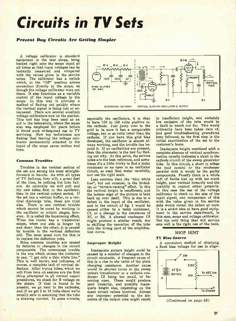
Circuits in TV Sets Present Day Circuits Are Getting Simpler
A voltage calibrator is standard equipment in the best shops, being hooked right onto the scope input at all times so that input voltages can be instantly measured and compared with the values given in the service notes. The calibrator has a switch which, in the "Off" position allows connection directly to the scope, as though the voltage calibrator were not there. It also functions as a variable control of the input voltage to the scope. In this way it provides a method of finding out quickly where the vertical signal is being lost or at-tenuated. There are several excellent voltage calibrators now on the market. This tool has long been used as an aid in the laboratory, where the scope also was employed for years before it found such widespread use in TV servicing. Now top technicians are finding that leaving the voltage cali-brator permanently attached to the input of the scope saves motion and time.
Common Troubles
Troubles in the vertical section of the set are among the most straight-forward to handle. As with all types of TV failures, they will, a great deal of the time, be nothing but tube fail-ure. S o naturally we will pull and try new tubes first in the oscillator, then in the vertical output socket. If the set has a vertical buffer, or a ver-tical discharge tube, these are tried also. There is one vertical trouble which cannot be cured by working in the oscillator or output stages, how-ever. It is called the keystoning effect. When the raster has a trapezoidal shape, when one side is longer up and down than the other, it is caused by trouble in the vertical deflection coil. The most usual cure for this is to replace the deflection yoke. More common troubles are caused
by failures or changes in the circuit components. The commonest trouble is the one which causes the customer to say, "I get only a thin white line." This is well known and indicates, of course, a complete lack of vertical de-flection. After trying tubes, which we will from here on assume are the first thing attempted in all normal repair procedures, we check for B voltage on the plates. If that is found to be present, we go next to the cathodes, and if we get 2 to 13 volts there we're usually safe in assuming that the tube is drawing current. In some circuits,
especially the oscillators, it is okay to have 100 to 150 volts positive on the cathode. Just jump over to the grid to be sure it has a comparable voltage, ten or so volts lower than the cathode. If you have this grid bias developed, the oscillator is almost al-ways working, and the trouble lies be-yond it. If no oscillations are present, then the ohmmeter is the tool for find-ing out why. At this point, the service notes are the best reference, and some-times it's a little tricky to find a leaky condenser or an open in an oscillator circuit, so read that meter carefully, and use the right scale.
Less common than the "thin white line", but not unusual, is the folded-up, or "curtain-raising" effect. In this the vertical height is insufficient, and the bottom edge of the picture is bent back up over itself. This is due to a defect in the input of the oscillator, and in the circuit of fig. 1 would be caused either by a leaky condenser, C7, or a change in the resistance of R7, or R6. A shorted condenser C6 might produce a similar result, due to shifting the operation of the tube onto the wrong part of the amplifica-tion curve.
Improper Height
Inadequate picture height could be caused by a number of changes in the circuit constants. A frequent cause of this is a rise in the value of the plate charging resistance. Another cause would be shorted turns in the sweep output transformer or a cathode con-denser C3 being too small, or be-coming open. These would produce poor linearity, and possibly inade-quate height also, depending on the exact circuit values involved. Almost any improper potential on the ele-ments of the output tube might result
in insufficient height, and certainly low emission of the tube would be a fault to watch out for. This would ordinarily have been taken care of, had good troubleshooting procedures been followed, as the first step in the initial examination of the set in the customer's home.
Inadequate height combined with a complete absence of vertical synchron-ization usually indicates a short in the cathode circuit of the sweep generator tube. In this circuit, a short in either the hold control or the condenser parallel with it would be the guilty components. Finally there is a whole raft of faults tied up with too much height, poor vertical linearity and the inability to control either properly. In this case the use of the voltage calibrator to check on the size of the input signal, and comparison of this with the value given in the service data would reveal the defect at once. It is a smart idea to have good equip-ment in the service department, in this case, scope and voltage calibrator. But tile only thing that will service sets well is the right use of the tools.
SHOP HINT
TIV Bias Source
A convenient method of obtaining a fixed bias voltage for use in align-
(Continued on page 48)
27

How New Automatic Focus One Design Replaces Both Electrostatic-Focus and Magnetic-Focus Types.
By Charles Graham, Technical Editor
• After changes in the design of cathode-ray picture tubes which have involved TV sets (and consequently servicemen) with five different beam focus-and-deflection systems, a means has at last been devised which pro-vides a simpler way of focusing the electron beam than have any of the previous five. In addition, there are a number of advantages attendant upon this design which will further simplify the task of the technician who finds himself confronted with the job of replacing a weak or burned-out picture tube, or convert-ing a small screen set to a larger size.
History of Developments
When non-mechanical TV was in its infancy there were two electron guns used. One was in CRT's like the present 5 and 7 inch oscilloscope tubes, and both beam deflection and beam focus were accomplished electro-statically. The other was a combina-tion of magnetic deflection and elec-trostatic focus. This design was used in tubes as large as the 12 inch size. Unfortunately, when the circuit con-stants, line voltage, etc., varied, often the degree of focus did also. The difficulty of manufacturing
these guns resulted in higher priced tubes, and with the advent of tubes with wide deflection angles, the guns were unable to produce pictures of sufficient quality. Meanwhile set designers switched
over to the system of magnetic deflec-tion and magnetic focus which is now familiar, and which is still the most widely employed system. When short-ages were threatened last year, and it became clear that sooner or later set designs would have to be pared of excess metals, tube engineers went to work to try eliminating focus coil
Procedure For Installing Automatic-focus Tubes
I. Remove focus coil from neck assembly.
2. Install centering device only when no variable DC cen-tering is available through the yoke.
3. Plug new type CRT in and start operation.
4. Change ion trap if necessary. Correct type stated by tube mfr., and depends on amount of second anode voltage. Trap is adjusted for max brightness only.
and focus magnet. Improvements in quality control of electron-gun pro-duction, and advances in research al-lowed them to come up with a system of electromagnetic deflection and elec-trostatic focus which was better than that obtainable before magnetic focus had become universal. Too, this time they were able to apply electrostatic focus to tubes of even a 20-inch diag-onal (a size which was regarded so huge two years before that the tube had to be specially ordered, and it sold in the trade for over $200!). A large number of these tubes,
called electrostatically - focused, or simply "electrostatics", are today be-ing used in TV sets. But although the use of electrostatics does save copper and cobalt (in focus coils and permanent magnets), it requires a focus voltage rectifier tube, a potenti-ometer, and at least three other small parts.
Low-voltage Focus
A partial solution to this problem (the requirement for the parts which make up the focus anode supply) was found soon after when some companies started engineering and producing low-voltage electrostatics. These picture tubes required, instead of one-quarter the second anode vol-tage, or about 2500-3000 V., only a
Fig. I. On the left Is shown a diagram of the electron gun for the older type of electro-static focus. At the right may be seen the new automatic-focus electron gun.
few hundred volts. This eliminated need for the focus rectifier tube and some other parts, but it still called for a focus potentiometer across the B+ supply. Now on the market, both for re-
placement tubes and as initial equip-ment in new TV receivers, are auto-matic-focus tubes. This means that whereas in all previous models there has been some sort of adjustment (either a manual one, as with perma-nent-magnet focus devices, or an elec-trical control to vary the focus cur-rent or potential) now the serviceman will be required to make no manual adjustment of beam focus at all.
Zero Voltage Focus
In sets which use electrostatically focused tubes the new type tube can be substituted directly. No changes are necessary. Of course the focus control ceases to have any function.
As will be observed in the accom-panying drawing, the electron gun of the new picture tube is similar in con-struction to the previous electrostatic type. The main difference is in the shape and placement of the focus anode. This electrode, together with the other grids and the second anode, forms an electrostatic lens. The pur-pose of the lens is to keep the electron beam sharp, of constant size, and as nearly circular in shape as is pos-sible, throughout its trip down and across the face of the tube. The resistor shown in the circuit
between the focus anode and the cathode provides isolation for the focus anode for two reasons: 1. It reduces the input capacity of the tube in the case of cathode video drive. 2. Some manufacturers use lit-tle filtering of the second anode sup-ply. Thus anode supply pulses might be coupled to the tube through the interelectrode capacity of the focus electrode were it not for the isolating resistor.
It was found that by increasing the
28

Picture Tube Operates Requires Neither Focusing Coil Nor Electrode Supply
diameter of the focus electrode and having it overlap rather than fit be-tween the two adjacent elements, it was possible to make many of the gun dimensions less critical. It also al-allowed more substantial physical mounting for this electrode, as can be seen in the photograph of the electron gun, fig. 2.
In sets which have electromagneti-cally-focused tubes as original equip-ment, the focus coil can simply be dis-mounted from the neck assembly and taped down on the side of the chassis out of the way. Or the focus coil may be removed completely and resistor of the proper size installed to take the place of the focus coil. (In the case of permanent focus magnets, naturally there is no need to keep the magnet once the new tube is in-stalled.)
FOCUS Regulation
When the focus potential is a siz-able percentage of the second anode voltage, as in the case of electro-static-focused tubes, variations in the focus potential, or in the second anode voltage can cause a change in the degree of focus attained unless these voltages vary in direct propor-tion. This is one problem partially eliminated in the development of the low-voltage electrosiatistics. By re-ducing the percentage of the second anode voltage which the focus poten-tial represented, better regulation of the beam focus in relation to potential variations was accomplished. But it was still only a relative degree of regulation.*
In developing this newest electron gun, for automatic-focus tubes, Du-Mont engineers found that they had achieved almost perfect regulation of
• A high degree of regulation, or good regu-lation is attained when the ratio of variation in the output or product is small compared to changes in the supply or the size of the load. Thus a power supply would be described as having poor regulation if doubling its load from normal cut the voltage supplied in half.
Fig. 2. Photograph shows DuMont electron gun for no-focus voltage picture tube.
Fig. 3. DuMont set on left has simpler neck assembly due to new style picture tube. Small centering magnet at rear of yoke is required only on with sets having no DC centering•
beam focus. That is, through the de-sign of the electrostatic lens system in the electron gun, they had made the degree of focus sharpness almost entirely independent of reasonable variations in the second anode volt-age. (Naturally, lowering of anode voltage will still produce dimmer pic-tures.) In addition, variations in beam current which previously caused changes in the size of the spot and focus were lessened in the new gun.
Finally, the new design increased the amount of the normal focus inde-pendence of line voltage variations and set warm-up. In the earlier sets, it was often necessary to readjust the focus control due to the warm-up.
Customer neglect of focus adjust-ment has much of the time resulted in an inferior picture which was not the fault of the set or installation. This tube removes the necessity for that adjustment.
Because of the shape of the new electrostatic lens system, there ap-pears to be slightly better resolution of the beam at the edges of the pic-tures. This too has been a problem with some other tubes.
Conversion Steps
In converting sets the advantage of using this type of tube may be easily seen. In conversions previously it was necessary to go through three separ-ate steps:
1. Cabinet work.
2. Deflection circuit changes — (a) usually changing horizontal
output stage for mor e sweep and higher second supply.
(b) changing yoke from 50 to 70 degrees.
3. Focus changes due to higher anode voltage, (and sometimes due to the requirements of the tube itself.) (a) More focus current was usu-
ally required. (b) Frequently a different focus
coil was required.
(c) The range of the focus control often had to be changed.
In converting to larger tube sizes with the automatic-focus type the third set of conversion requirements is eliminated. As a sales point, too, the customer can be honestly assured that this tube is the "latest" engi-neering development in cathode-ray tubes.
Cuts Inventory
The advantage of using this type of picture tube for all replacements is obvious when one considers that in-stead of having to keep on hand a 17-inch electrostatic-focus tube and a 17-inch magnetic focus tube, the service-man or dealer can take care of either type with only one 17-inch replace-ment. The same applies to the 20-inch replacement stock problem. In this way the inventory of replace-ment picture tubes for smaller shops may safely be halved. The cost of the automatic focus
tubes is at present set the same as the price of the equal size rectang-ular tubes of other focus systems. DuMont is producing the 21KP4A, the 17KP4 and the 20JP4. Thomas Electronics is producing some of these tubes, and GE has announced the 17RP4. At presstime other manufac-turers had indicated that they would soon produce these tubes, but could not yet make official announcements.
29

Printed Circuits Widely New Units Gain Acceptance Because of Saving of Labor and Space
• When Grandad made his first superregenerative receiver from plans in the daily paper, he was told to use a lead pencil mark between "A" and "B", to make a resistor.
This simple resistor was one of the first clues to present-day printed-cir-cuit techniques, and as a starter it lay almost absolutely still for about twenty years. Present-day printed-circuits have several advantages, yet the keynote to them all is simplicity. The pencil mark represents about the simplest component we could hope for, and our modern printed circuits aren't that simple. But they are made by mass-production methods, which is something Grandad wasn't able to accomplish. Today there are over 15 million printed circuit com-ponents in civilian sets. (Figures on military sets are still secret, but it is known that previous to civilian use the military necessity for com-pact parts and assemblies required large quantities of such components.)
Because they are showing up in-creasingly in television receivers and other common electronic devices, a brief discussion of the construction, applications, and advantages of printed circuits is in order. Just as miniature tubes were de-
veloped during the last war, and have now come into general use, so it is likely that a great many other minis-turizations, including printed circuits, will soon be used in everyday sets even more than they are now, due to defense research. When "printed circuits" are men-
tioned, many technicians tend to think of the stamped metal antennas which have been widely employed in AC-DC sets. Or they recall the turret tuner which has its coils photo-etched in thin copper. But the type of printed circuit most widely employed today is neither of these. Printed circuits as they are used at present in TV and radio receivers are flat rectangular plates, generally between 14" and 1%" long, about an inch or less high, and 1/4 " thick. They are ceramic plates onto which have been bonded metal-lic paints and compounds to form re-sistances and small condensers in cir-cuits where these parts are commonly used in the various sets with the same values frequently chosen. The verti-cal integrator plate, for example (See Fig. 2) is a combination of several condensers and several resistors in a circuit which is pretty standardized throughout the industry. Since the same circuit values can be used for this circuit (the vertical integrating
Fig. I. Olympic AC-DC radio set shown above employs a printed circuit triode coupling plate (upper right). The smaller printed cir-cuit plate directly above is a diode load net-work. At right here is reproduced part of schematic from Sentinel service notes show-ing triode coupling plate.
network) in most TV sets, the cii - cuit lends itself admirably to the ust of a printed circuit plate. Anothei place where standardization of cir-cuitry has progressed in the industry to a comparable point is in the cou-pling network between the output of the det-AVC-first audio stage and the power amplifier stage of small radios. Consequently, a large number of sets now employ printed circuit plates in this part of their circuit. These components are most widely
used in TV sets. Most hearing aids use printed circuits, naturally, be-cause of the extreme small size avail-able, and many portable and AC-DC table sets are including them. Both resistors and condensers may
be made by the printed circuit tech-nique, and when both are fabricated in various combinations, they save not only space, but a great deal of time and work in the manufacture of the circuits they are part of. This is be-cause they incorporate so many cir-cuit components into one piece, with the common, internal connections al-ready made, and hidden in the body of the piece.
See Fig. 1 for diagrams which compare the number of soldering and wiring connections normally required in the construction of a plate coupling network with the number needed with the use of a printed circuit unit. In this audio coupling network between a pentode voltage amplifier and the
12AV6 or 12 AIS
orr-avc-•, COuPLING AAAAA
Is
• 5.
next stage, it will be seen that ordi-narily eleven various points and five components would have to be con-nected together with eight or more soldering and twisting operations. With the printed circuit unit this is reduced to five solderng points, and one component. The best example of this sort of
saving is in the vertical integrator plate, however. Here eight parts be-come one, and twelve or more inter-connections become three soldering operations! There are over twenty different
printed circuit components being pro-duced today. Of these, the vertical integrator network (See drawing, Fig. 2 is the most widely employed, being used at present in over three million TV receivers. Running a close second is the printed circuit coupling plate*, with over 2,750,000 in portable and table radios. There are also over a million small filter networks* al-ready sold to set manufacturers and almost as many printed output
30

Used in Current Sets in the Manufacture and Servicing of Radio Ti and Equipment
stages*. Fifty or so manufacturers have already used these components in one or more sets each. From the above statistics, it may
be seen that printed circuits, though comparatively new, are rapidly spreading in use. With the speed-up of research and development which the present defense electronics pro-gram is bringing about we may rea-sonably look forward in the near fu-ture to even more widespread employ-ment of these parts. The National Bureau of Standards
has already conducted a large pro-gram aimed at producing improve-ments in printed circuit design for manufacturers to the armed forces. This program has developed some im-portant advances in design which are undouptedly incorporated in military equipment, but are still for security
*Centrelab's trademarked names for these com-ponents are Couplet.. Filmic. and Audit, re-spectively.
Fig. 2. Photograph above shows most common printed circuit component in use today. It is the vertical integrator plate. Typical manu-facturer's service diagram is partially repro-duced at loft to show (Inside dotted lines) the eight parts which are Included in single printed circuit part. Only three external soldering connections are made.
reasons not in civilian use. When they can be released for public benefit, they will change the appearance of home receivers even more than did the advances made during the last war. In another type of printed circuit
metallic paints are sprayed or painted onto insulating surfaces to form the "wire" connections between various circuit components. A different com-position of paint is subsequently ap-plied at the proper points to serve as resistor. This sort of printed cir-cuit is used in many hearing aids.
Naturally, such resistors cannot be employed in parts of the circuit which carry substantial current. They are, generally speaking, good in cir-cuits where up to 1 or 2 watt values are usually specified, but not in power output or supply sections.
If part of a printed circuit were to be replaced, as for example, in a hearing aid, the simplest solution would be replacement of the entire printed unit. Failing that, in many cases, it is possible to replace just the faulty condenser or resistor. If this cannot be done, as for example, when several resistors and condensers are contained physically in the same unit, then it is necessary to replace the entire printed unit.
In some cases it is possible to re-place just the faulty part, with paint from kits which are now commercially available for the purpose. If a re-sistor were to be replaced, metallic paint of the appropriate kind would
be applied, the resulting resistance measured with a voltohmeter, and more paint added, or some scraped away, until the proper resistance value was obtained.
Regular condensers (or even re-sistors) can be soldered into printed circuit, as parts replacements, if care is observed not to damage the insulat-ing plates and other circuit parts. Solder which has some silver content is needed for this sort of soldering, however. One caution is in order. When a printed circuit plate is to be replaced in a receiver, often the num-bers which identify the leads project-ing from the plate are numbered in a different order from the lead num-bers which are on the original part. In such cases, the new part should have its leads soldered in the same order, counting from left to right, into the circuit, without regard for the numbers shown. A physical com-parison is used—not the numbers. The advantages which the manu-
facturer obtains from the use of printed circuit components in his seta may be summarized as follows: (1) Several parts may be replaced by one part. (2) Installation time on the production line is saved through fewer connections to be wired and soldered. (3) Since there are fewer connections to be made by the assem-blers, there is lower probability of mistakes. (4) Space is saved — al-lowing smaller chassis, or more room for other, outsized, or non-standard parts. These advantages are leading more
and more manufacturers to the use of printed circuit components, so we will continue to find more and more of them in the radio and TV sets of today and tomorrow.
Motorola table set shown below uses connec-tions with a P.C. plate.
31

Servicing and Maintaining Key to Profitable Phonograph Maintenance is
• The step-child of many service de-partments is the handling of record-changer repairs, and allied phono-graph problems. Yet today there is renewed interest in phonograph rec-ords as an entertainment medium, due at least in part to the advent of microgroove. With the upsurge in sales of records has come a st,epup in the number of phonograph service calls. In addition, the use of fine-groove records has made the listener more readily aware of minor flaws in the operation of the changing mech-anism. This is because here the out-put of the needle is smaller in rela-tion to machine-noise than it is in the case of regular groove records. A further complication is the introduc-tion of better quality sound into present-day combinations, resulting also in "better" reproduction of rumble, scratch and distortion.
In the past, many shops have re-garded changer service as such an un-important part of the work that they have not even had a rack to mount the èhanger on when it came in. A recent informal survey by the writer found, racks in less than one out of four radio repair departments. Yet all the shops stated that they did changer repairs and further, that such repairs were increasing in volume.
Most phonograph repair jobs start with an outside service call. It is important that the outside technician know his own limitations; that he be able to correctly and quickly rec-ognize when a changer repair is not the kind to be done in the home. Many jobs that should have been done in the shop have become need-lessly complicated by having been first attempted in the customer's house without proper equipment.
Take the case of Jim Doakes, serv-iceman. After putting a new needle in Mrs. Jones' changer (an old single-speed one which had a lot of cast white metal parts) he showed her how well the new needle sounded. Jim was about to leave when Mrs. Jones asked him if there was any-thing he could do about the fact that sometimes the arm did not drop just right. He figured it couldn't be very difficult, even though he was unfa-miliar with the adjustments on this model changer. After looking in vain for a positioning adjustment he lifted up the changer and, seeing what he thought was a small nut on the arm spindle, tried to loosen it with a spin-tite. Of course it wasn't a nut, but just a piece of casting and it broke off, disabling the machine. Jim tried to fix it, but with no success. (It happened there was no such adjust-ment at all on this early-type ma-chine.) Finally, he had to leave a very irate Mrs. Jones and promise to come back the next day with a new part. It took three weeks to get a replacement part for this old model changer, and even then the changer had to be picked up and brought into the shop for the replacement. The dealer lost a lot of good-will and money in this case because (a) the technician was so anxious to please that he attempted a job he was un-familiar with, and (b) he attempted a job in the home which should have been done in the shop. The outside man must be able to
tell when the job cannot properly be accomplished in the home, and he must be sufficiently self-assured to tell the customer, firmly where neces-sary, that the job cannot be done correctly on the spot. He must not use this means to
Below, in a typical factory service photo Is shown a side view of Webster-Chicago's model 106.
AUTOMATIC-MANUAL CONTROL KNOB
7« PICKUP ARM REST
POSITIONING CAM SPRING
POSITIONING CAM NEEDLE SETDOWN ADJUSTMENT
TRIP ARM
PICKUP ARM RAISING DISC
cover up a lack of proper equipment being carried on the outside call. This equipment should be contained in a kit kept separately for just the times when needed and should include at least the following:
A stroboscopic disc, for use under an AC light source — for checking speed of turntable.
A phono test cartridge, with shielded lead 3 ft. to 21 ft. long and clips at its end. (Removable-needle type).
Carbon tet and/or alcohol, and cloth.
NOT ENOUGH TENSION ON CARRIAGE SPRING
SMALL BELT STRETCHED
BINDING AT SOUR BEARING
GREASE OR OIL ON IDLER WHEEL
IDLER WHEEL DETECTIVE OR BENT
LINE VOLTAGE LOW ? moron perenvEnumn• BENT?)
Above: Mechanism is part of V-M changer used in many combinations today.
Pressure gauge for measuring weight of needle on groove.
Lubricating grease and light ma-chine oil.
Small kit of replacement needles, both sapphire and metal.
With the kit of phonograph ad-justment equipment listed above, the serviceman should be able to correct most minor troubles and make most adjustments. It is assumed that in addition he will have the usual com-plete radioman's set of tools with him.
Repair jobs which cannot be handled outside will also require, be-yond the things listed for the outside phono kit, manufacturer's factory data, universal AC (fused) test leads for checking motors, rack for mount-ing the changer and turning it upside down when necessary. For testing the operation of mech-
anisms after they have been com-pletely repaired and adjusted, a stack of records, both 10" and 12", some 12" 33 RPM, and a few 45 RPM discs should be kept in the service depart-ment. There are also available test rec-
ords which will rapidly check the changing cycle of record changers. These records have only about one groove per inch, so that they run in to the center in four or five revolutions.
32

Phono Record Changers Use of Proper Equipment. Including 'tlateufacturers Data
In shops where high-quality ma-chines are sold or repaired, a test record for checking the frequency response of the entire system will prove helpful. These records are made by major record companies, and carry grooves modulated with fre-quencies from 50 cycles to 10,000 cycles, thus providing a check not only of the needle and cartridge, but of the amplifier and speaker also. In cases where rumble is the complaint, it is helpful to have an amplifier and speaker with very good bass response available for checking this point.
Do It in the Shop
Whenever the trouble is not merely an adjustment which could have been made with a screwdriver, or by re-placing the cartridge or needle, the changer should be brought into the shop. The technician who attempts to repair Mrs. Jones' changer in her home beyond the aforementioned repairs is asking for trouble. In-volved changer repairs cannot and should not be attempted without a proper rack and the benefit either of manufacturer's diagrams, or years of experience.
Caution! See that no one in your shop ever puts a changer, regardless of make, directly on the floor. It takes only a very slight bump to bend or break the parts of many changers. See that pieces of card-board are available at all times where changers may be set down.
After the changer is in the shop, it should be set in the rack and, if in operating condition at all, started running. Put one or more records on it and observe its action and see what it fails to do.
If the complaint is "rumble", "squeaking", "thumping", etc., that is, if it is mechanical trouble, but not a failure, then the section of this article dealing with Maintenance should be referred to.
If the trouble is a failure to prop-erly accomplish some part of its dropping, changing, or playing cycle, usually the manufacturer's service information will list the common fail-ures and the points to check for eliminating them. To check mechanical operations,
move the turntable by hand on the rack. Move it in the reverse direc-tion if it is jammed. But be careful. A light hand and several years of experience are helpful here. Be cer-tain what you're doing, particularly if it involves bending or twisting any part of a mechanism. There are al-
Mounted on adjustable changer rack for easier, faster repair is a Garrard 3 speed changer.
most no repairs that call for this, so stay away from it unless the manu-facturer's literature specifically rec-ommends it.
Bridging the test cartridge across the leads of the old head will show at once whether the trouble is in the cartridge or in the set. Most crystals will read high resistance if weak, distorted or dead, and will therefore not materially affect the input im-pedance of the test head. (Normal resistance of crystal heads is about 2, 3, or up to 10 megs. Variable re-luctance heads read much lower-200 to 500 ohms being typical.) Bad tone which affects only the
high notes will usually be caused by a worn or chipped needle, if the fault is present only on phono (not on radio). Particularly with microgroove records the problem of worn needles will be more prevalent than it was with 78s. This is true because (a) the wearing pressure is much greater on the tip of the needle than with 78, despite much lighter total weight, (b) "Permanent" needles are in much greater demand and wider usage than ever before. (c) Present day equipment is capable of much better fidelity and high frequency response, showing up needle wear much more readily than did earlier, poorer equip-ment.
If the distortion is severe, and is accompanied by a loss in. volume, the crystal should be suspected. A quick easy check for crystal failure of this sort is to press the crystal light-
ly to one side of the groove. If this restores most of the proper tone, then one of the two elements of the crys-tal is dead. Replacement of the unit is the only remedy. When the motor fails to turn and
the servicer has determined that there is no simple failure of contact in one of the interconnecting cables or plugs between the main AC line and the motor, then it is reasonable to suspect the motor itself. Most phono motors for 110 V, 60 cycles, read about 10-20 ohms, a reading much lower than this or consider-ably higher will indicate shorted turns, or if high resistance, an open in the motor. It usually does not pay to rewind such motors, so a re-placement motor must be installed. More and more changers, partic-
ularly in the three-speed category, and in the expensive sets with ex-tended frequency response, will give rumble troubles or speed variation troubles. There are three speed vari-ation difficulties which can occur. The most common, and easiest to
recognize, is "wow." So-called, be-cause of the sound of the word, it is caused by periodic changes in the speed at which the turntable goes around. These changes are very slow (from about change per second on 33 RPM, at the slowest, to a few per second). They are usually due to defects or foreign ma-terial in turntable, turntable bearing, main idler, or some other fairly slow
(Continued on. page 41 )
33

Crystal Diodes Replace Use of Germanium Units Found Increasing in 1951 Models; Simplification of
• First used in military electronic equipment during World War II, ger-manium crystal diodes have recently been proving their worth in consumer products, particularly television sets. They are now available for replace-ment purposes, as well as in original equipment.
Briefly, these units are basically the same as the crystals we knew in early crystal receivers: that is, they are rectifiers. It is mainly the character-istics and constructional features of the new crystals which make them dif-ferent from early crystals. The latter usually used crystals of the mineral Galena; a "cats whisker" or fine wire was used to find a "hot spot" on the crystal; and the characteristic of the unit was that it conducted better in one direction than the other. The 1N23's that were used in radar em-ployed crystals of silicon, and the units that are being used now in TV (1N34, etc.) utilize crystals of ger-manium.
Many Advantages Seen
One characteristic of the silicon and germanium crystal diodes is that it isn't necessary to search for a hot spot with the catswhisker, and there-tore the latter can be permanently fixed. This means that the crystal diode can be sealed up in a cartridge, which greatly increased its utility. Other characteristics of these diodes are: Relatively flat response at Very High Frequencies over a relatively wide dynamic range of signal levels: low forward resistance, which con-tributes to good rectification efficiency at low signal levels; transit time, in-terelectrode capacitance and internal noise, which are limiting factors in the use of vacuum tubes at VHF and UHF, are relatively negligible in the germanium diodes; and finally, of course, when compared with a tube, the germanium diode with pigtails can be soldered in like a resistor-takes little space, needs no filament wiring or other voltages, and no tube socket.
Reverse Current Passed
On the negative side, it should be mentioned that germanium crystal di-odes will not withstand as high in-verse voltages nor as high ambient temperatures as will equivalent vacuum tubes, such as the 6AL5. Also, it is well to note that while the back resistance is much higher than the forward resistance (the ratio is about 100:1 for germaniums) it is neverthe-less a finite resistance (roughly about 100,000 ohms), and current will flow in the inverse direction. A vacuum tube diode, on the other hand, would
pass no current if its anode were made negative. However,-and this should really
have been listed under the advantages -the life of a germanium diode (esti-mated at 10,000 hours) greatly ex-ceeds that of a vacuum tube when op-erated properly, observing the peak inverse voltage and operating tem-perature. Table 1 shows some of the pertinent features of the more popu-lar types of germanium crystal diodes used in TV receivers.
Fig. 3: Proper polarity indications for manium diodes. Pr.
For circuit connection purposes, the characteristics of the crystal diodes are shown in figure 3. Considering the interior of the crystal, the catswhisker is comparable to the anode of a recti-fier and the germanium crystal is the cathode. As would be expected, the plate is considered to be the positive end and the cathode the negative. As in a tube rectifier circuit, however, the output is taken from the cathode. This
AC INPUT
Fig. 4: Output taken from cathode (minus) seed of diode.
is shown in the simplified schematic of figure 4. On the Sylvania (1N34, 1N60) crystals, the cathode end is marked with a green band. On the General Electric (1N64, 1N65) crys-tals, the cathode end is the larger end (opposite to the tapered end). Earlier Sylvania diodes had a "plus" and "minus" sign instead of the green band. The newer GE crystals also have a band on the cathode end. The "minus" end corresponds to the cath-ode end and should be placed in the circuit so that it faces the "plus DC" output end of the circuit. This is im-portant due to the relatively low in-verse rating of the units and the fact that ,they will pass current in the wrong direction.
Several Uses In TV Sets
A typical video detector circuit using a germanium crystal diode is
Table I I N34 1N60 1N64
Peak Inverse Volts 75 70 20. Inverse current @ -50V .8ma (not known) Ambient Temp. Range-50° to -j- 75°C for all types - * Fahrenheit = 9/5 (C -I- 32)
I N65 6AL5 85 330
.2ma
Table II Current TV models using a germanium crystal diode as video detector
Make Andrea Arvin
Brunswick Emerson Freed GE Hallicrafters Hoffman
Magnavox
Majestic Mercury North Amer. Philips Pilot Setchell-Carlson SMA Co. Stewart .Warner Tele-Tone Trod Zenith
Models Crystal Normandy IN34 212ITM, 2123TM, 2120CM, 2I26CM, 2 I24CCM, 3080T, 216ITM, 2160CM, IN64 2164CM, 2I62CCM 616, 6161, 1116 1N34 673, 660, 665, 664 1N60 54, 55, 56, 68, 101, 103, 104 IN64 All current models INM 805, 806, 809, 810 IN60 All current model; 1N60 248,348 IN34 Cosmopolitan IN36 French Provincial 1N60 All current models IN64 6111, 6114,9114 IN34 1200, 588 1N34 127, 163, 166 IN60 150, 1500, 1500LP 1N34 111,114,117 IN34 9200A IN64 All except Imperial models IN64 All current models IN34 All current models INM
34

Tubes in New TV Sets
iiC-171 G 1010 450 111
Ilanisfacture and Servicing as Well as Improved Performance Noted
Many Other Types and Uses for Germaniums
WINO
40.•
V-30 CRYSTAL 11705
12-174 e475 r 17,
5•17111 7 4000 , ev,
5.171
15 -CIS 3Iek
573 SC
G-172 # 'Mr
5.177 — •1110K Vo
ér 2
5.172
10« IC
60^,
30V ,
v• 11
I2AU7 350 SYNC CLIPPER Sh.,TUR
lr - 130 -V I
751.1G
184
520
5-1112 5211
shown in figure 5. The receiver is General Electric 16T3, 16T4, 16C113 and 16C116.
Still another application of the ger-manium crystal is shown in figure 6, in which is shown a portion of the schematic of the Stromberg Carlson 119 series receivers (Empire, Georgian, 18th Century and Chinese Classic). V-30, a 1N65, is used as the 2nd Sync Clipper. This operates in conjunction with V-17 (1st Sync Clipper) and V-18 (3rd Sync Clipper and Splitter) to remove large noise pulses, to main-tain the proper blanking level and to separate the sync signals from the video.
Used For DC Restorer
Germanium diodes may also be used for DC restorers. Substitution of a 1N65 for a 6AL5 DC restorer in .the GE models 12T3 and 12T4 is shown in figure 7. Many of the late model sets, however, eliminate the necessity for DC reinsertion by using direct coupling from the video amplifier to the grid of the kinescope.
Of course, the uses for germanium diodes outlined in this article are but a few of the many possible uses. The purpose of this article was only to show uses found in current model TV receivers. Nor are all the many types of diodes which are available described here, but only those found in the aforementioned TV sets. There are some types which accommodate back voltages up to 200 volts, and there are some (silicon types) which are useful at frequencies up to 10,000 MC.
Fig. 5 (at right) a por-tion of the schematic for GE TV sets 1673, 1614, 16C113 and 16C-116. The symbol beside the diode is the physi-cal appearance of the unit as shown in fig. 3. Fig. 6 (Above) Strom-berg Carlson 119 series. Due to an error in the original diagram, the symbol for V-30, the 1N65, should be re-versed from that shown, so that the bar desig-nation (the cathode) connects to the plate circuit of V-17. Receiv-ers are wired correctly in this respect. Fig. 7 (below) GE model 1213, showing how a crystal diode can be substi-tuted for V2, 6AL5, the DC restorer.
The use of germanium crystal diodes in a wide variety of equipment [close to 3 million will have been sold by the end of this year( can be considered still in its in-fancy; and the use of these units in home TV receivers, covered in this article, represents but one of the many growing markets for them. At present approximately half a dozen out of more than 35 available types are being employed in TV sets. In addition to this use, many are finding their way into radios (particularly FM), test and measur-ing equipment, commercial and government communications equipment, research equip-ment, etc., and new uses for them are be-ing uncovered daily.
V6 3,to IF
E8C5
.26 47
YI 0E1: )N64
i • C265 I - I " --191-41-7) I
T ELMS I .=L254
01. C-7._71
L
• e •
L256 3Itirg 2. 8265 '600
V 7A 1sT VIDEC
1/212AT 7
.7.268
15 z2n.
la 24 6800
5265 2-2.1G
2
35

Suppressing Local Oscillator Radiation in TV Receivers
Proper shielding, grounding, and orientation of oscillator components; adequate
rejection in coupling and power supply networks reduces chassis radiation
By JOHN P. l'AiN Dly 171E Allen B. DuMont Labs., Inc. 2 Main Ave., Passaic, IV. J.
DURING the last three years, there has been a mounting en-
gineering interest in the suppression of incidental radiation capable of in-terfering with radio broadcasting and communication services. This interest stems from an engineering confer-ence on oscillator radiation held by the FCC on Nov. 1, 1949. At this conference, attention was drawn by the FCC to the fact that during the period July 1, 1948 to June 30, 1949, 1,730 complaints of interference to broadcasting services were received.' These complaints covered many
sources of interference, but the most rapidly growing source was that from the LO (local oscillator) of TV re-ceivers. As a result of this confer-ence, the RTMA Committee on radio interference was reorganized and an active compaign was begun on Jan. 11, 1950 in New York City. At this time, the R15 Committee of RTMA
TABLE I: Radiation Data on
Typical Untreated TV Receiver
Channel
4
5
6
7
8
9
10 11
12
13
Antenna
Plus Chassis Field Strength
i(V Meter.
52
100
168
426
450
474
900
1478
1850
1865
Chassis Alone
Field Strengtn itV/Meter.
34
90
113
464
487
592
972 1296
1924
1872
* Measurements by standard IRE method.
RTMA limits: low VHF band 50 pm/meter; high VHF band 150 pm/meter;
CI band use cat.
IF CouP11341 !landaus Filter A.
eie =.10oen Circuit Local Oscil. Voltage Rio= External Damping On Local Oscli.
e Coupling Reactance To Mixer Grid
Cio Input Cop. of Mixer
Rin input Resistance of Mixer Circuit and Tube
Cop= Mixer Grid-Plate Capacitance
Co = Mixer Output Capacity
Fig. 1: Shielded local oscillator equivalent circuit. R-F and bandpass filters introduce sufficient attenuation at local oscillator frequencies to make their ground returns relatively unimportant
was made aware of the magnitude of the problem and the FCC desire for an early solution. The work of this committee and
that of the IRE Committee on radio receiver test methods culminated in the adoption of two standards: (1) a standard of allowable radiation limits for TV and FM receivers by the RTMA, and (2) a standard on "Method of Measurement of Spuri-ous Radiation of Frequency Modu-lation and Television Receivers" (50 IRE17 PSI) by the IRE Committee. Once the TV design engineer had a specific limit and method of measur-ing performance against that limit, it was possible for him to design eco-nomical TV receivers to meet the specified radiation limits with a rea-sonable safety factor. There are several sources of inci-
dental radiation in a TV receiver. These are, in order of importance: high frequency LO, horizontal de-flection system and associated high voltage generator, video i-f amplifier, sound i-f amplifier, and video ampli-fier. By far the most serious of these has been the high frequency LO radiation. The remainder of this arti-cle will deal with methods and tech-niques useful in the design of a TV receiver and particularly its r-f
tuner to meet the new RTMA radia-tion limits on LO radiation. Space does not permit a discussion of the other forms of interference here. The LO radiation problem may
again be subdivided into "antenna radiation" and "chassis and/or power line" radiation. The power line radi-ation situation will be considered a special case of so-called chassis radi-ation. This is due to the fact that excitation of the power line is a re-sult of the same leakage of LO en-ergy from the r-f tuner that excites the whole chassis. By antenna radia-tion, we mean that component of radiated interference which may be eliminated by the removal of the transmission line from the receiver and the substitution of a matched dummy load resistor. The remaining interfering radiation will be referred to as "chassis radiation." Experience to date has indicated
that when starting with an existing receiver design, by far the most se-rious component of radiation is the chassis radiation. See Table 1 for supporting data. This is not neces-sarily true once the design has been altered to minimize chassis radiation. The progress of a radiation reduction investigation is analogous to the problem of the archeologist. When
36

he uncovers one layer of interesting relics, has carefully dusted off and restored each one of his important finds, and is about to sit back and enjoy a well earned rest, he discovers that there is yet another layer peer-ing through the dust to mock him. This results in a certain amount of jockeying to and fro from chassis to antenna radiation and the need for constant field testing of "improve-ments."
Unfortunately, as the engineer be-gins to peruse the available literature on these problems of radiation reduc-tion, he soon finds that the bulk of the literature is concerned with an-tenna radiation and mentions little
of the problems of chassis radiation. This is natural in view of the fact that prior to the wide sale of TV and FM receivers which operate in the VHF region, most receivers, both home and communication, operated in a frequency range such that the chassis was very small compared to a half wavelength, hence minimizing the importance of chassis radiation. However, in the case of TV re-
ceivers, the chassis usually is big enough to approach half-wave res-onance in the 174 to 216 Mc TV band and therefore is an efficient radiator. Once this situation is realized, the next step is usually to pull the dust cover off the nearest available VHF
SHIELD WALL
FROM 47041- 470.n. 10 K
+
FROM HTR. SUPPLY
FROM AGC 47K 47K
Capacitor
mTix0ER
TO RF AMP HTR
TO RF AMP GRID
Note: C=. 500 Jeff Low Inductance Type Feed - Thru
First Anti-Resonance Above 300 MC
L= I/..h With C Distributed 0.5
R. All Watt With Very Short Leeds To Feed Thru Capacitors.
Fig. 3: Filter arrangement designed to prevent spurious resonances within oscillator tuning range
Fig. 4: Spark-plate capacitors employed to filter 8+; heater and AGC leads passing through shield wall
Fig. 2: Typical shield construction
standard signal generator and view, in awe, the elegant shielding em-ployed by the manufacturer of the instrument. It would be nice if it were practical for the TV designer to construct the LO of his TV re-ceiver in a manner similar to the signal generator. Unfortunately, however, the economics of the situa-tion prevent this course of action. The buying public would not be favorably impressed with an increase in list price consistent with employ-ment of signal generator techniques.
Signal Generator Techniques
However, it is possible for the TV design engineer to profit immensely by careful consideration of the tech-niques employed by the signal gen-erator manufacturer. The principles exemplified by this construction may be applied in a much less expensive manner to a TV tuner. Following a further discussion of the basic prob-lem, we shall discuss such techniques as applied to a TV receiver. Reference to an elementary text
on radiation discloses that we get a radiation component whenever an electromagnetic field is accelerated in a medium of finite velocity of propagation. If this radiated energy is not totally reflected, the original electromagnetic field experiences an energy loss. It is the job of the de-signer to provide either for the re-flection or the absorption of this energy which would normally be lost to the LO and gained by the receiver in the next apartment. In order to prevent the radiation
of energy by the receiver chassis, it is obvious that we must prevent the excitation of that chassis by the LO energy or totally reflect the energy radiated by the chassis. Since it is wasteful of material to attempt to confine a field within such a large volume, the most economical ap-proach is that of preventing the ex-citation of the chassis. Thus we may state that the basic
problem confronting us as design
37

- CONNECTS POINTS OF OSC.
CURRENT FLOW IN CHASSIS.
Fig. SA: (I.) Poor oscillator design cousu conduction currents In chas is. Fig. SI: (R) Good oscillator design reduces chassis
engineers is to confine the electro-magnetic fields due to the LO to the immediate vicinity of the LO. The degree of this confinement is, of course, established by the limits that one is trying to reach. The RTMA limits on radiation have been es-tablished with the intent of protect-ing the maximum amount of service area without imposing an impossible economic burden on the buying public. There are several characteristics
peculiar to TV receivers which aid the program of LO radiation reduc-tion. These are:
a. The oscillator is operated on the high frequency side of the de-sired signal, separated from the sound carrier by 21 or 41 Mc in modern receivers. This separa-tion permits relatively simple and inexpensive selective cir-cuits greatly to attenuate the oscillator signal before it reaches the r-f amplifier plate circuit.
b. The i-f is removed by at least one octave from the oscillator frequency. This permits i-f band pass circuits of proper design to discriminate greatly against the oscillator signal.
c. A higher degree of r-f circuit shielding is required by a TV receiver for many reasons other than oscillator radiation sup-pression. It only remains to ex-tend this shielding to include the problem of oscillator radia-tion.
Fig. 6: Continuous inductance tuning unit
There are also some problems in the TV receiver which complicate a low radiation design. These are:
a. The need for a high degree of economy and reproducibility in the design.
b. The circuits located within the shielded compartments must be
currents
available for quick servicing. c. The chassis used in TV receiv-
ers are large enough to be rather efficient radiators, especially in the 174 to 216 Mc band.
d. The use of metal cabinets may, under some circumstances, in-
TABLE Il: Local Oscillator Radiation Reduction Results
Antenna Plus Chassis Radiation Chassis Radiation Alone
TV Channel
Before After µV/Meter* V/Meter*
Before After µV/Meter* V/Meter*
4 52 11 34 Less than five s 100 11 90 Less than five 6 168 7.3 113 Less than five
7 426 32 464 7.2 e 450 28 487 7.0 9 474 52 592 7.2 10 900 27 972 5.6 11 1478 26 1296 6.2 12 1850 41 1924 13.
13 1865 29 1872 25.
* IRE Standard Method
RTMA Limits: low UHF Band SO uy/meter; high VHF Band 150 uy/meter
Fig. 7: Grld-separation amplifier and equivalent circuit. Plate current in input has LO component
38

crease the effective radiation surface.
e. Our present defense effort has made it necessary for the de-signer of civilian goods to con-serve metals, especially the highly conductive ones which are most desirable for r-f shielding.
With the preceding facts in mind, the designer then proceeds to the task of selecting circuits and physi-cal layouts to accomplish his ends. The following rather obvious points are listed so that it may be easier to follow a detailed discussion of each point. These are the general means for restricting the electromagnetic fields of the oscillator to the vicinity of the LO. Fig. 1 illustrates some of the following points:
a. The oscillator and mixer circuits must be enclosed in a conduct-ing shield as completely as pos-sible. Shield joints must be de-signed in accordance with the principle of minimum leakage consistent with ease of shield removal and economy of manu-facture. The shield should be fastened to the next larger sup-port member at points of as near equal potential as possible to minimize excitation of the larger surfaces.
b. All power supply leads entering the above mentioned compart-ment must be filtered for r-f.
c. The oscillator must be so de-signed that it produces a mini-mum of current in the sur-rounding metal. This may be accomplished by the following general methods: 1. Single point grounding must
be used for the entire oscilla-tor circuit.
2. The oscillator inductor must be oriented so that its field induces minimum currents in the surrounding metal.
3. The oscillator inductor field may have to be restricte& by such means as a complete coil shield or vestigial shielding such as a shorted turn sur-rounding that coil.
d. Since the mixer or frequency converter tube is driven by the LO, usually via control grid in-jection, it is necessary to design the band pass networks asso-ciated with the mixer tube for minimum transmission at os-cillator frequencies.
The obvious, but uneconomical, way to design oscillator shielding is to enclose the oscillator by means of soldered, "water-tight" joints in the shielding and possibly the use of double shielding. This is obviously
not a reasonable approach to high production. The approach should be that since the shield must be inex-pensive and readily removable, ex-treme emphasis should be placed on minimizing the magnitude of cur-rents induced in the shielding by the LO. It is of even greater importance to prevent the actual conduction of oscillator current by the chassis and/or shielding. Once the oscillator currents in the shielding have been reduced to a sufficiently low value, the need for precious metals in the shield compartments and the need for multitudinous grounding fingers or mounting screws is minimized. Almost any crude metal box of rather low conductivity material, such as thinly plated steel, will ade-quately confine the electrostatic field, providing that there are no holes or slots in the shield across which a po-tential difference can exist. This can usually be accomplished, for the electrostatic field, by proper orienta-tion of holes and slots. However, such is not the case for the electro-magnetic field.
The presence of any holes will per-mit magnetic lines of force to "bulge" through the opening, thus permitting the excitation of currents upon the exterior of the compartment shield. These currents then excite the main chassis which is a fairly efficient radiator and the damage is done. From that point on, additional filter-ing of leads or careful placing of components within the oscillator compartment will be to no avail. Thus holes must be avoided at all costs. This means that supply leads must leave the compartment in a manner that prevents magnetic lines of force from accompanying the wire. The means of accomplishing this with a filter will be discussed later. One hole that is very difficult to avoid is that for the tuning shaft. It is possible to minimize leakage of this nature by use of either an insu-lated shaft in an elongated bushing (waveguide below cut-off attenua-tor) or by careful grounding of a metallic shaft together with care in minimizing excitation of the shaft by oscillator currents inside of the compartment. This latter approach is by far the most practical in a TV tuner. It admittedly does not allow the same degree of attenuation as the former method, but experience has proven it to be adequate.
Shield joints, whether fastened by screws or by spring pressure, should have as large an overlap as possible to minimize leakage which is inevi-table in joints between metals that are not of the highest possible con-ductivity and so carefully formed
Suppressing L-0 Radiation
that they provide an almost water-tight joint. This is the big point of departure from signal generator technique. Grounding fingers are no doubt desirable, but they are equally uneconomical. Since shields in TV receivers must be made of sheet metal in great quantity and at low cost, the tolerances that may be spe-cified are of necessity loose. This means that the designer must be very cautious, especially when designing the joints, to provide for the neces-sary allowances and at the same time accomplish contact over as great an area as possible. A practical means for accomplishing this (see Fig. 2) lies in the use of a gasket of a metal textile to provide good contact be-tween mating non-planar surfaces. A further point of departure from
signal generator technique lies in the choice of metals for the shield. Brass, copper, and silver are entirely un-economical as base metals and are further unthinkable in view of the requirements of the defense pro-gram. On the other hand, high con-ductivity metals are desirable, in that smaller thicknesses are neces-sary for a given attenuation of a confined field and that good joints are more readily obtained. A metal thickness of about 10 times the "skin depth" is necessary to produce an attenuation of approximately 86 db in the field intensity. This would re-quire approximately .003" of copper if the minimum frequency were 80 mc. This amount can be most eco-nomically produced by "overlay" techniques.
If overlays of copper are used, the shields should be formed with the copper on the inside. However, ex-perience has shown that cold rolled steel will provide adequate attenua-tion in thicknesses of 0.030" or more, if the joints are plated with at least 0.0005" of copper. This latter shield, together with the previously dis-cussed care in minimizing current density in the shielding will produce very satisfactory results. The main enemy of the effectiveness of such shielding is corrosion and care must be taken in handling and fabrication to minimize such tendencies. The necessity for adequate low-
pass filtering in the power supply leads is obvious. In the case of high voltage and automatic gain control lines, it is possible to use series re-sistor, shunt capacity filters. It is important that the capacitors not ex-perience any anti-resonant effects
within the tuning range of the oscil-lator. The use of series resistors of a few few hundred ohms on both
39

the input and output of this filter usually prevents resonance in the supply leads exterior to the tuner. It is usually necessary to use LC filters in the filament leads to avoid excessive voltage drop. These filters must be designed to prevent any spurious resonances in the tuning range of the oscillator. See Fig. 3 for typical filters. Several types of capacitors are suitable for use in these filters. One type has been used by automobile radio manufacturers for years under the name of "spark-plate" capacitors. Fig. 4 illustrates such capacitors. This technique is applicable to the TV receiver if ma-terial of adequate insulation resist-ance and dielectric strength is used. Another alternative is the use of either disk or cylinder "feed-through" types of ceramic capacitors. As mentioned earlier, it is of ex-
treme importance to minimize the flow of oscillator tank currents in the chassis or shields of the tuner. Fig. 5 A shows an oscillator circuit that is very bad from the standpoint of causing conduction currents to flow in the chassis. A change to the circuit of Fig. 5 B will eliminate this portion of the difficulty.
It still remains to locate the oscil-lator inductor so that its magnetic field links the chassis and shielding as little as possible. In switch, turret, or permeability tuners, this can be readily acComplished by winding a coil with a fairly high ratio of length
to diameter and the use of high permeability core material to confine the magnetic field, plus spacing from the chassis of at least two coil diam-eters. Most pure permeability tuners suffer from a rapid increase in chas-sis radiation at the high end of the tuning range. This may be due to the increased extent of the field about the oscillator coil when the core is fully removed from the coil. Hence, the use of combined permeability and eddy current shielding tuning is in-dicated. Naturally, the conducting shield used for eddy current shield-ing inductance variation must sur-round the inductor if the desired confinement of the field is to be obtained. Some forms of continuous induct-
ance tuning devices such as shown in Fig. 6, have a naturally extensive magnetic field. Since, for minimum back-lash, the oscillator inductor must be close to the tuning shaft, it is somewhat difficult to minimize ex-citation of the shaft. A partial solu-tion to this problem has been the use of a conducting ring in close prox-imity to the oscillator coil field. This ring can also be used as an aid to tracking, due to its effect on the oscillator coil inductance. In the high VHF band, the effect of the ring is small, due to its looser cou-pling to the coil. Fortunately the shaft excitation has been found to be a major problem only in the 90 to 110 me region where the shielding of the
1.0
0.8
Q6
0.4
0.2 41 in
o Q.
cr • .10
La .08
.06 -J
CC
.04
.02
.01
1 1 3db Bw.IIMC A
eio o
—
B -12.5 d b
n eo
r -158db
-16.7 db
A - 23d b
A B
FOR LOCAL 24
OSC. MC 1.F LOCAL OSC.
FOR 44 MC IF,
10 20 40 60 80 100 200
FREQUENCY (MC)
400 600800
oscillator coil field is relatively great. The problem of confining the local
oscillator energy which is conducted from the shielded compartment by the antenna and i-f output leads is one which is readily susceptible to quantitative analysis. However, the results of analyses of this nature must be viewed in the light of maxi-mum attainable figures, rather than the preordained result of following the schematic diagram that was ana-lysed. This departure of results from theory can be minimized if care is taken in the analysis to include all the significant reactances. The usual approach is to assume
that for reverse transmission, the r-f amplifier tube is a passive network composed of the interelectrode ca-pacitances and lead inductances. This is not true in general, but only in special cases. Pentode r-f amplifiers, in which there are a minimum of common impedances in the cathode circuit may be successfully analysed as a passive network. Cathode sepa-ration triode r-f amplifiers usually follow this theory also. However, the grid-plate capacity is not the only coupling. Above 200 me, the cathode lead inductance may allow direct conduction of oscillator energy into the grid circuit, even with C p, per-fectly neutralized. A somewhat different condition
occurs with grid-separation ampli-fiers, since the plate current flows in the input (cathode) circuit. The
Fig. 8: (L) Comparison of selectivity of anti-resonant circuit (A) wit h high selectivity input (B) shows greater attenuation of (8) pre-
vents reverse transmission of LO frequencies through r-f stage. Fig. 9: Mixer bandpass couplings circuits, stray reactances dotted.
40

plate current contains a component of LO signal due to the rather low plate resistance of the triode and this component appears across the transformed antenna impedance. See Fig. 7 for details. Normally, one would expect that the antenna com-ponent of LO signal due to a finite Rp would only be noticeable at fre-quencies so low that Xcpk was equal to or greater than R. This occurs about 65 mc for Cpk = 0.5 uuf. Some-times an effect occurs above 200 Mc in which the antenna radiation varies with gp, of the tube. This has been traced to regeneration in the r-f amplifier at frequencies well above the signal frequency, but close to the oscillator frequency. This is usually a result of the grid circuit impedance increasing due to L. (see Fig. 7). Thus, it is essential to provide a high degree of antenna circuit selectivity at oscillator frequency if a grid-separation triode r-f amplifier is used. Such an input circuit and its selectivity curve compared with a simple anti-resonant circuit of equal Q is shown in Fig. 8. The popular "cascode" or driven grounded grid
circuit affords another means of achieving high antenna circuit se-lectivity together with the passive isolation of the cathode separation input triode. Much more can be said about
proper design of interstage coupling circuits for LO energy suppression, but would be a subject for a paper in itself. Suffice it to say that r-f band-pass circuits between the an-tenna and mixer grid should have maximum "above band" rejection and those between mixer plate and r-f grid should have similar abilities. It is also essential that the stray re-actances associated with practical components should be negligible all through the LO tuning range. Fig. 9 illustrates some of these circuits, to-gether with the dangerous stray re-actances which are shown dotted. The degree of improvement in
radiation reduction that can be achieved by the application of some of the previously discussed tech-niques is shown in Table II. The fig-ures shown are results of measure-ment of a complete receiver, before and after radiation proofing, by the
IRE field method. In conclusion, a note of caution
should be sounded. It is possible, by careful circuit "tailoring" to produce substantial reductions in antenna ra-diation due to presence of two or more sources of leakage of opposite phase. In TV receivers, the fre-quency range is so great that such "bucking" is unlikely to hold over the frequency range and is certain to be impossible of attainment in mass production. It is necessary, if uniform results are to be achieved, studiously to avoid such cancellation phenomena. It is far more economi-cal, in the long run, to put a few more cents into a good sheet metal design that is subject to simple in-spection techniques, than to rely on "tricks" which will pile up rejects, or worse still, place radiating receivers in customers' hands. Thanks are extended to Mr. E. G.
Mannerberg without whose coopera-tion this paper could not have been completed.
1. K. A. Chittick, "Report of Engineering Con-ference on Oscillator Radiation of the F.C.C. on Nov. 1, 1949."
UHF ANTENNAS
(Continued from page 8 )
b. Utilize built-in or cabinet-top antennas—principally in strong signal areas.
c. Install a separate UHF antenna on the existing mast, feeding both UHF and VHF antennas into a common transmission line by using a special coupling network.
d. Make an entirely separate UHF installation if the loca-tion of the VHF antenna is not satisfactory, or move the exist-ing VHF mast to a positron suitable for both services.
Record Changers
(Continued from page 33)
turning part. The second common variation in
the speed at which the turntable re-volves is "flutter." This is a more rapid periodic change in the speed of rotation. It may be roughly said to go from about 15 times a second up to the point where it is no longer noticeable. Most people will react to flutter by saying, "the phonograph
is going too slow", or "it sounds slow, or sick." This is, of course, partly true since variations of this sort will usually be accompanied by some slowing down. But the slowing down is not what they hear. Con-trary to the opinion of most people, they cannot tell when a record is going very slightly slow or very slightly fast unless they are ex-tremely familiar with the particular record. When they say it's going slow, the odds are ten to one it has flutter. The third trouble is actual slowing
down of the turntable. On governor-controlled phonographs, which are almost out of existence as new equip-ment, the cause is usually a lack of lubrication, or an accumulation of dirt and grease in the governor. In synchronous motors, which most phonographs today have, the trouble may be too heavy a pickup arm, a broken needle point, cold motor (grease thick—gets back to normal after warmup), dirt on any moving part, or lubricant dried up. The rub-ber idlers or belts should also be checked. Maintenance on record changers
consists of checking for proper op-eration, cleaning, and lubricating. The proper cleaning agents are car-bon tetrachloride (alcohol is usually OK, but be careful of the material it is used on) and a cloth, with a small brush for getting into tight places. All surfaces such as the working surfaces of the motor pulleys, idler pulleys, idler wheels, inside turn-
table wheels, and friction surfaces in governors, should be carefully cleaned, allowed to dry, and then run for a while. At the same time, before test-running, the bearing sur-faces (or inside), of these parts should be cleaned of oil and dirt, and then covered very lightly with a light grade of machine oil. (It cannot be said too often that much of the trouble in new or recently-repaired changers comes from over-generous lubrication. What may not seem like excess oil when the parts are at rest quickly gets distributed to other parts of the machine as soon as the changer starts operating.) Be care-ful not to lubricate brake surfaces or certain parts of governors. Manu-facturers' literature always shows a pictorial diagram of the places for lubrication. In addition to these places, many changers require a couple of drops at each end of the motor every few months. In a large percentage of these motors, there are small pieces of felt near the bearing ends of the motor axle which are in-tended to hold the lubricating oil. (Do not saturate these—use just two drops in most cases.
Often a flat on the main idler wheel can be eliminated by taking the rubber wheel off and reversing it; that is, turning it inside out.
After the repair has been made, a stock of records should be placed on the changer and allowed to play through two or three times before the changer is marked "ready" and put aside for delivery.
41

New York TV Stations Utilize ERP comparisons for transmitters at the same location but on different frequencies
first time. FCC's permission to increase powers adds approximately 10,000 square miles
By JOHN H. BATTISON Consulting Editor
in 1949 when the announce-2-4 ment was made that WJZ-TV would share the top or the Empire State Building with WNBT, consid-erable interest in the project was en-gendered by the television engineer-ing fraternity. Here was a challenge to the ingenuity and resourcefullness of engineers in applying previously known principles of diplexing to four carriers from adjacent radiators.
Later, in rapid succession it was announced that WCBS-TV, WABD, and WPIX would also erect antennas on the same tower and plans for a multiple unit transmitting antenna were drawn up. Then in July of this year it was announced that WATV would probably join the other five telecasters on the top of the highest building in the world. Final authorii,y has been received from the FCC for modification of WATV's construction permit to make this change in location. As a first step in the ending of the
freeze, the FCC recently removed its restriction on the use of maximum power by the existing 107 TV sta-tions. One result of removing the power limitations is that most exist-ing stations can increase the output of their transmitters to the full rated output which is 5 kw for all except community stations. The removal of the power limita-
tion means that WNBT is now oper-ating from the Empire State Build-ing with 14.5 kw, WJZ-TV is using 17.0 kw from the same location and WPIX is radiating 21.7 also from the new antenna. WABD and WCBS-TV are radiating 14.25 kw and 20.1 kw respectively from their original installations, and WOR-TV is radiat-ing 22 kw. The factor of greatest interest to
both engineers and telecasters in all these power increases is what hap-pens to the service areas of stations when the power is raised. In all cases referred to above the effective radiated power (ERP) is used since this is a factor which influences cov-erage assuming height and frequency are similar. For the first time in television history it is possible to compare the effective coverage of television stations operating with similar high powers and from the same antenna height-within a few score feet, which is negligible at 1400 ft. above sea level.
So far in these tests it has not been possible to obtain comparative coverage maps due to the short time which has elapsed and the fact that there are various methods of ex-pressing service area currently in use. For instance, NBC and CBS use the 0.1 MV/M contour as the limit of service while some other stations use the earlier 0.5 MV/M contour as the measure of service. The FCC has in-stituted a new grade of service area connotation by labelling the areas grade "A", and grade "B". Also at this time the three stations using
ERP COMPARISON FOR TV STATIONS IN NEW YORK AREA
1.
Station
2.
Old Power Transmitter ERP
Old Transmitter 3. Locations
Power under Order 5 Transmitter ERP
4. Power under Order 5
Empire State Transmitter ERP
WABD 4.0 KW-V 2.5 KW-A
I 14.25 KW-V I 9.45 KW-A
same as 2 4 KW Transmitter
5 KW-V 2.5 KW-A
16.7 KW-V 8.4 KW-A
WCBS-TV 3.0 KW-V 2.5 KW-A
13.7 KW-V 5 KW-V 10.2 KW-A 2.5 KW-A
20.1 KW-V 10.2 KW-A
5 KW-V 2.5 KW-A
20 KW-V 10 KW-A
wiz-Tv 0.815 KW-V 0.800 KW-A
3 KW-V 1 5 KW-V 3 KW-A I 2.5 KW-A
17.0 KW-V 9.0 KW-A same as (3)
WNBT 1.42 KW-V 1.15 KW-A
5.2 KW-V I 4.2 KW-A
I 5 KW-V I 2.5 KW-A
18.3 KW-V 9.2 KW-A same as (3)
WOR-TV 2.04 KW-V 2.5 KW-A
9.0 KW-V 11.0 KW-A
5 KW-V 2.5 KW-A
22 KW-V 11 KW-A
WPIX 3.5 KW-V 1.75 KW-A
16.3 KW-V 5 KW-V 8.17 KW-A 2.5 KW-A
26.3 KW-V 13.2 KW-A
5 KW-V I 20.8 KW-V 2.5 KW-A I 10.6 KW-A
WATV 5 KW-V 2.5 KW-A
30.5 KW-V same as 15.3 KW-A
(2) l 5 KW-V I 22.5 KW-V l 2.5 KW-A I 11.8 KW-A
the Empire State facilities have not completed full measurements. Prob-ably it will not be until WCBS and WABD join the other stations that a really comprehensive and compara-tive survey will be made. After all, one field trip would suffice to meas-ure all five, or six, transmitter strengths, and it would result in economy in manpower and effort. As far as WNBT is concerned, an
increase in service area of about 9 miles radius has been obtained with the increase of power to 14.5 kw ERP. This results in adding about 10,000 square miles to the total serv-ice area. The antenna was rephased slightly to increase the signal to the nearby areas, but this did not affect the service contour. The major effect of these power
increases has been to extend the service area in all directions and pro-vide a usable signal in areas that be-fore were considered "fringe." In addition, while improving the signal strength more or less uniformly, it has the advantage that at the points where previously there was interfer-ence between co-channel stations the signal strength at these points has increased so that even if the inter-ference contour has not moved fur-ther away the signal strength, and hence the signal to noise ratio has improved.
Same Coverage Increase
In the case of WJZ-TV with a power increase to 17 kw the 0.5 MV/M contour has moved out to 57 miles and the 0.1 MV/M contour to approximately 75 miles. Probably all the stations on the new tower will experience about the same relative increase in signal strength coverage. In many cases the FCC authorization merely specified that power might be increased to the maximum 5 kw rated output of the transmitter, rather than a definite ERP.
It is quite possible that WNBT ex-perienced the greatest improvement in signal with the power increase since it previously had a very low ERP due to its high antenna and consequent severe limitation to keep
42

Unique Antenna Installation now possible for
to service area
within the FCC's 50 kw at 500 ft. figure. As reports are received from other stations and final measure-ments are made it will be interesting to compare the effect of raising the powers of other low power artificially limited stations. When WATV commences operation
from the Empire State Building, it is expected to use a series of dipoles mounted around the base of the tower in much the same manner as WCBS-TV is using at present. Per-haps the results of using channel 13 at this height and with high power will present some extremely interest-ing phenomena in the field of long distance reception. The comparison between the Em-
pire State transmissions and those from WOR-TV's antenna in North Bergen may point up the effect of an increase in height, i.e. the difference between the WOR tower and the Empire State Building. However, the effect of frequency will be elimi-nated since the Empire State Build-ing transmissions occur on frequen-cies which bracket that of WOR-TV.
70-75 MILE POST-FREEZE 0.1 MV/M "SERVICE AREA"
MONTIGELL O
NEWBURGH
60 MILE PRE-FREEZE 0.1 MV/M/ /
/ "SERVICE AREA"
fi / 57 MILE POST-FREEZE
"RATED OUTPUT" 0.5 VM/M CONTOUR
NEW BRUNSW
47 MILE PRE-FREEZE */ 0.5 MV/M CONTOUR CHANNELS 2-13
TRENTON
NEW YORK
ASBURY PARK
TOMS RIVER
NEW HAVEN
UGHKEEPSIE
o
',DAN BURY
BRIDGEPORT
I$ io Leg
o MINEOLA
SANDY HOOK
Expanding service area as seen by TV stations in New York City
The only revised coverage map thus far available is from WOR-TV and is based on the increase in power and was compiled by means of increased
during last 3 years
mail response after the event. As soon as WCBS-TV and WABD join the tower it is expected that revised coverage maps will be available.
Substitute Condensers
Everyone at some time has found it necessary to substitute a condenser
or resistor in a circuit momentarily to test the part in question. The usual method is to hold the substitute in your hand, or tack it in with a solder-ing iron. The test fixture shown en-ables the servicer to insert a con-denser or resistor between two bind-
Service Shortcuts
ing posts, and with the aid of two flexible leads and clips, to make posi-tive contact. This eliminates the need for soldering, or the hazard of hold-ing the part. Should it be necessary to make contact at a difficult location, the clips can be clipped on long in-sulated screwdrivers or regular test prods.—Grant Nonnamaker, Grant's Radio, 6548 Torresdale Ave., Phila-delphia 35, Penna.
Soldering Tip
From R. Whitman, Greenwich, Conn.: When soldering leads on RCA phono jacks, speaker plugs, Amphenol plugs and the like, most people hold the tip upside down and try to melt solder down into it. This gets a lot of solder on the outside of the pin, but very little inside where it is needed. I have found the following method very easy, secure and neat: Put the tip down on the iron

Fig. 1: Test towers at RCA, Camden. Foreground tower will support antennas for channels 7 and 11; left to right are antennas for channels 11-4. 2-5, and 5-7.
Fig. 2: SVVR. measurements made on ch. 7 radiator with ch. 5 antenna adjacent to it.
Designing By JOHN H. BATTISON
Consulting Editor
WHEN the decision to install more than one television sta-
tion on the Empire State Building was made, the primary consideration was interaction between stations. The first expectation was that four telecasters would share the new tower; however, later this figure was increased to five. In the antenna design only interaction between an-tennas can be considered. To date some preliminary tests have been made on the coupling between adja-cent antennas which indicate that a decoupling of the order of 26 db can be achieved. This figure was obtained on the basis of previous experience.
Probably the only good feature of the late November and early Decem-ber hurricanes experienced in the east was the very thorough workout and lifetest it gave the test antennas at the Camden plant of the Radio Corporation of America. Fig. 1 shows a general view of the test ground with the antennas mounted on towers to simulate the actual proximities to be encountered in practice. Rain, snow, heat and cold as well as fumes and corrosive air about as bad as that encountered in New York have impinged on these radiators but they have withstood all that the elements can do. In New York City, also, the steelwork re-ceived a workout when the hurricane hit town, but from all reports no trouble was encountered. The location of the antennas has
already been discussed in the No-vember issue of TELE-TECH (cov-er), it is their close proximity which was expected to present many diffi-culties in connection with isolating the antennas. Many tests have been carried out to determine the amount of interaction between the adjacent antennas.
In order to simulate actual condi-tions on top of the Empire State Building as nearly as possible, four test towers were built on which each pair of adjacent antennas will be mounted. This test will yield im-pedance data over the channel as well as the amount of interaction. It also simulates assembly problems on top of the building. Four towers
Fig. 3: 20 Kw diplexer and equalizer unit for the lower channel radiating system.

World's Highest TV Antennas Many problems concerning interaction between adjacent antennas are
solved in the TV-FM transmitter installation on Empire State Building
Fig. 4: Left, closeup of a feed line transformer and junction box. Right, triplexing transformer for channel 4 radiator.
are needed for Channels 2 and 5, 5 and 7, 7 and 11, and 11 and 4.
In each test operation signals at the visual and aural frequencies were fed into the deplexer and passed through the power equalizer (if re-quired) and then to the antenna. In the antennas tested both antennas are assembled completely. An Oscil-lator is fed into one antenna and a field intensity meter is connected to the other to determine the amount of coupling. When the proper fre-quency is applied to the transmit-ting antenna the amount of power pickup by the adjacent antenna is measured. A figure of 26 db down is considered satisfactory.
Types of Antennas
The antennas used are of two types; channels two, five, seven and eleven use the RCA U Super gain an-tenna while channel 4 uses the RCA Super Turnstile antenna. For sta-tions WCBS-TV and WABD special emergency antenna switching ar-rangements are used so that the an-tennas can be operated as either 2, 3, or 5 bay radiators. The reason is presumably to allow emergency operation in the event that trouble occurs in the whole system. The an-tennas are split and separate trans-mission lines, diplexers, and power equalizers, are used for each section. In normal operation the power is di-vided as shown in Fig. 5 and all sec-tions are used, but if trouble develops in either section it can be cut out and the transmitter operated into the good unit. Switching is manual and carried out simply. It is under-stood that the other stations have different emergency facilities so that this feature will not be used.
Stations using the Super Gain antenna were given their choice of single-line or double-line feed. The low band stations chose single-line feed while the high band chose double-line feed. Low-band stations will use a bridge-type power equal-izer which tends to broad-band the antennas. Broad banding problems are more severe on the low bands since Channel 2, for instance, occu-pies a 10% band width compared to 3% for Channel 11.
For most of the antennas the feed-ers running from the junction boxes illustrated in Fig. 7 are RG 35/U with the metal armour removed. IIowever in some of the illustrations RG 35/U with the braid still on it is shown. The impedance is 75 ohms. Few of the mechanical details of
tower construction appear to have interfered with the electrical design
of the antennas, in fact that the only one which has been discussed was the need to reduce the width of the channel 11 reflectors due to the small size of the latter, and the large (about 8 inch) steel angle which comprises the sides of the tower at this point. Thus it became necessary to simulate these solid reflectors by the use of sheet metal during the tests. The pole for mounting the chan-
nel 4 Super Turnstile presented a problem inasmuch as it had to be cut into ten foot lengths to get it in the elevators and up to the top of the Empire State Building. The connec-tions to the Super Turnstile Antenna are unusual in that flexible RG 35/U is used rather than the normally used rigid copper transmission lines. The turnstile type of antenna had
(Continued on page 48)
Fig. 5: (Left) Switching system provides whole or partial operation of low band antennas. Fig. 6 (Right) Set-up to measure degree of interaction between antennas.
E SAYS
V51 1% POWER
POWER
yCONNECTOR FOR WHOLE ANTENNA OR
SEPARATE SECTIONS
TOWER MOUNTING
POWER 1 K ¡ EQUALIZER I
'(LOW CHANNELS: i<
K
¡DUPLE XER
SIGNAL
GENERATOR
SIGNAL
GENERATOR
ANTENNA UNITS
SWR SLOTTED MEASURING
LINE
FIELD INTENSITY
METER
45

UHF-Converter Design Features More recent manufacturer's data provides additional
details on technical characteristics of TV tuners.
Mallory Converter
Utilizing a recently developed type tuner, this converter, designed by P. R. Mallory & Co. Inc., Indianapolis 6, Ind., covers the r-f range of 470 to 890 MC. The tuner used in this con-verter is of the three section type. It consists basically of two r-f cir-cuits overcoupled to provide a rela-tively constant band width, and the third section being used for the local oscillator which tunes 82 MC below the r-f band. The output of the oscil-lator is connected to a crystal diode as well as the incoming r-f signal. The output of the crystal goes to a low noise triode r-f amplifier which has a single broad tuned circuit in the input and a double tuned circuit in the output. The band width of the output circuit is approximately 12 MC wide so that it will cover the ad-jacent channels of 5 and 6. The choice of channels 5 and 6 was made because it was felt that a better noise figure could be obtained on the low TV bands, and also that the switch problem would be slightly easier. The output of the converter being at an r-f frequency of 5 and 6 enables it to be connected to any present day TV receiver. The power supply is of the trans-
former type using a tube rectifier and is strictly conventional. The an-off switch serves a dual function in that it switches the VHF antenna straight through the converter to the receiver antenna terminals when in the off position. When the converter is turned on the output of the con-verter is connected to the VHF re-ceiver. The UHF antenna is not
switched, but is connected to the first tuned circuit at all times. A 110 volt receptacle is provided on the back of the converter so that the television receiver may be plugged in and thus turned on and off with the converter. Installation of this converter is comparable to that of installing a booster on a present day TV receiver.
Stromberg-Carlson Converter
The new UHF television converter developed by Stromberg-Carlson is designed to operate on all Strom-berg-Carlson receivers as well as those of other manufacturers and to tune all of the 70 channels in the UHF band. It can be installed on existing television receivers without modification in a few minutes. The cabinet, shown in Fig. 2, is
styled in green leatherette and pro-portioned to harmonize with the tele-vision receiver. The outside dimen-sions are approximately 8 in. wide, 4 in. high and 6 in. deep. The unit weighs 51/2 pounds and has a power consumption of about 10 watts. Channel indicator, vernier tuning knob and function switch are all lo-cated on the right side of the unit. Top and bottom views of the chas-
sis are shown in Fig. 3 and Fig. 4. The converter is designed for con-nection between the antenna lead-in and the television receiver. Receiver power is obtained from a socket in the rear of the converter chassis which in turn is plugged directly into the ac line. A single three-posi-tion function switch provides the following combinations: 1. Off—Both
Fig. 1: (Above) Three section tuner used in P.R. Mallory's UHF-Converter (Below)
converter and television receiver; 2. VHF—a-c power to television re-ceiver on, VHF antenna directly con-nected to television input. Converter heaters on. 3. UHF—a-c power to both units and choice of separate UHF antenna, VHF antenna or built-in cabinet antenna depending upon signal conditions. The converter can be operated by
tuning the receiver to either of two channels (#5 or 6) which is not occupied by a local station. This choice Is made during installation by a switch in the rear of the con-verter chassis, which shifts the first IF tuning 6 MC. The bandswitch of the UHF pre-selector circuits is 12 MC., allowing this shift without loss of tracking. Selection of this IF is a compromise providing a mean be-tween the extremes of the high noise factor in the high channels and the undesirable spurious responses of the very low frequency channels. The rapid attenuation with increasing distance of UHF signals which might cause spurious interference
Figs. 2-4: (Left) Overall view of the Stromberg-Carlson UHF converter. (Center) Top and (Right) bottom view of chassis
46

Fig. 5: Schematic diagram of the Stromberg-Carlson UHF-Converter
appears to make it practical to use a lower IF than would otherwise be possible.
Mixer Circuits
In both the antenna and mixer circuits, the tuning elements are in-ductively padded in order to secure the proper tuning range. This is accomplished by extending both con-ductors of the antenna section and one of the conductors of the mixer section about 7/8 in. external to the tuning unit. The balanced 300-ohm antenna is coupled into the extended section of the tuning unit with the aid of an ungrounded loop. A combination of high-side capaci-
tive and inductive coupling is used between the antenna and mixer tuned circuits in order to provide a bandwidth of 12 MC. throughout the UHF band. The 1N72 crystal mixer is coupled capacitively to the mixer tuned circuit, and an RF choke provides a d-c return path for this circuit. (See Fig. 5)
Grounding of the low frequency ends of the antenna and mixer lines
and the grounding of the rotor of the antenna section eliminate spuri-ous suck-outs within the band. The oscillator design utilizes a
miniaturized version of the 6F4. A series trimmer condenser effectively sets the low frequency end of the tuning range, and a series trimmer inductance consisting of the grid and plate leads control the total range and the high frequency limit. This adjustment consists of varying the separation between these leads. "Holes" in the frequency range are avoided by using resistors rather than chokes in the plate and grid return circuits and by using dis-similar chokes in the cathode and ungrounded heater leads. A special UHF low-capacity tube socket is used to prevent bypassing the tuned circuit by the grid-plate socket ca-pacity. Tube "warm-up" drift, although
somewhat a function of individual tubes, is nearly complete within one minute after application of plate voltage, with heaters previously warmed up. This initial drift is minimized by using the lowest plate
power which will give reliable per-formance.
Complete shielding of the oscil-lator tube, circuit, and tuner section together with low oscillator plate voltage reduces oscillator radiation. The conversion loss of the crystal
mixer is overcome by the addition of a low noise amplifier. A "cas-code" circuit using a 6BQ7 tube was selected because of its inher-ently good noise factor. This circuit consists of a neutralized grounded cathode input section followed by a grounded grid stage. Both the input grid and the inter-
stage circuit of the cascode are ad-justed to have bandwidths of about 12 MC., i.e., to include both Chan-nels #5 and 6. The plate of the output triode, however, is adjusted for a 6 MC. bandwidth and a switch is provided on the rear of the chas-sis to select the desired channel. Economy is achieved by the use of a simple slide switch as a channel selector which varies the value of capacity in series with the plus B end of the plate tuning coil. Bal-anced output is used in order to
47
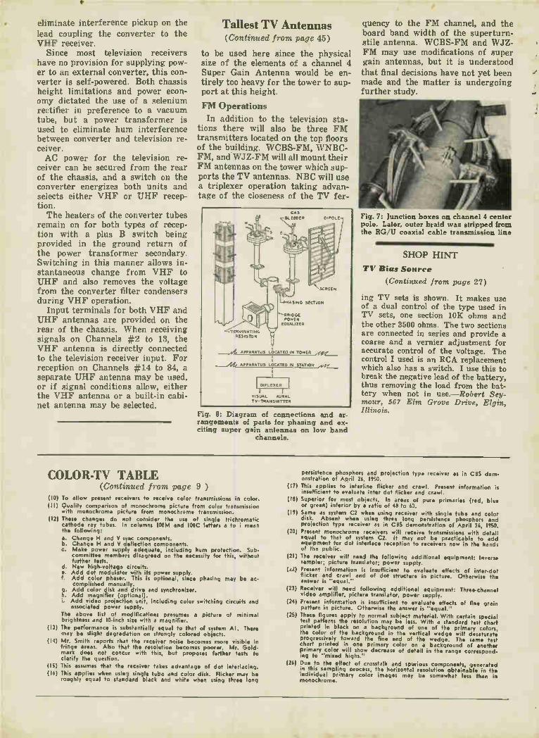
•
eliminate interference pickup on the lead coupling the converter to the VHF receiver.
Since most television receivers have no provision for supplying pow-er to an external converter, this con-verter is self-powered. Both chassis height limitations and power econ-omy dictated the use of a selenium rectifier in preference to a vacuum tube, but a power transformer is used to eliminate hum interference between converter and television re-ceiver. AC power for the television re-
ceiver can be secured from the rear of the chassis, and a switch on the converter energizes both units and selects either VHF or UHF recep-tion. The heaters of the converter tubes
remain on for both types of recep-tion with a plus B switch being provided in the ground return of the power transformer secondary. Switching in this manner allows in-stantaneous change from VHF to UHF and also removes the voltage from the converter filter condensers during VHF operation.
Input terminals for both VHF and UHF antennas are provided on the rear of the chassis. When receiving signals on Channels #2 to 13, the VHF antenna is directly connected to the television receiver input. For reception on Channels #14 to 84, a separate UHF antenna may be used, or if signal conditions allow, either the VHF antenna or a built-in cabi-net antenna may be selected.
Tallest TV Antennas (Continued from page 45)
to be used here since the physical size of the elements of a channel 4 Super Gain Antenna would be en-tirely too heavy for the tower to sup-port at this height.
FM Operations
In addition to the television sta-tions there will also be three FM transmitters located on the top floors of the building. WCBS-FM, WNBC-FM, and WJZ-FM will all mount their FM antennas on the tower which sup-ports the TV antennas. NBC will use a triplexer operation taking advan-tage of the closeness of the TV fer-
GAS
vs,B,Ls;E 10ER DIPOLE
SCREEN
RASING SECTION
BRIDGE POWER
EQUALIZER
T RUINATING RESISTOR
I
APPARATUS LOCATED IN
/://, APPARATUS LOCATED IN STATION 4,./•
DIPLEXER
VISUAL AURAL Tv-TRANSuITTER
Fig. 8: Diagram of connections and ar-
rangements of parts for phasing and ex-
citing super gain antennas on low band
channels.
quency to the FM channel, and the board band width of the superturn-stile antenna. WCBS-FM and WJZ-FM may use modifications of super gain antennas, but it is understood that final decisions have not yet been made and the matter is undergoing further study.
Fig. 7: Junction boxes on channel 4 center
pole. Later, outer braid was stripped from
the HG U coaxial cable transmission line
SHOP HINT
T1 Bias Source
(Continued from page 27)
ing TV sets is shown. It makes use of a dual control of the type used in TV sets, one section 10K ohms and the other 3500 ohms. The two sections are connected in series and provide a coarse and a vernier adjustment for accurate control of the voltage. The control I used is an RCA replacement which also has a switch. I use this to break the negative lead of the battery, thus removing the load from the bat-tery when not in use.—Robert Sey-mour, 567 Elm Grove Drive, Elgin, Illinois.
COLOR-TV TABLE (Continued from page 9 )
(10) To allow present receivers to receive color transmissions in color. (I I) Quality comparison of monochrome picture from color transmission
with monochrome picture from monochrome transmission.
(12) These changes do not consider the use of single trichromatic cathode ray tubes. In columns 108M and 108C letters a to i mean the following:
a. Change H and V Sync components. b. Change H and V deflection components. c. Make power supply adequate, including hum protection. Sub-
committee members disagreed on the necessity for this, without further tests.
d. New high-voltage circuits. e. Add dot modulator with its power supply. f. Add color phaser. This is optional, since phasing may be ac-
complished manually. g. Add color disk and drive and synchronizer. h. Add magnifier (optional). i. Add video projection unit, including color switching circuits and
associated power supply.
The above list of modifications presumes a picture of minimal brightness and 10-inch size with a magnifier.
(13) The performance is substantially equal to that of system Al. There may be slight degradation on strongly colored objects.
(14) Mr. Smith reports that the receiver noise becomes more visible in fringe areas. Also that the resolution becomes poorer. Mr. Gold-mark does not concur with this, but proposes further tests to clarify the question.
(15) This assumes that the receiver takes advantage of dot interlacing.
(16) This applies when using single tube and color disk. Flicker may be roughly equal to standard black and white when using three long
persistence phosphors and projection type receiver as in CBS dem-onstration of April 26, 1950.
(17) This applies to interline flicker and crawl. Present information is insufficient to evaluate inter dot flicker and crawl.
(18) Superior for most objects. In areas of pure primaries (red, blue or green) inferior by a ratio of 48 to 60.
(19) Same as system C2 when using receiver with single tube and color disk. Absent when using three long persistence phosphors and projection type receiver as in CBS demonstration of April 26, 1950.
(20) Present monochrome receivers will receive transmissions with detail equal to that of system C2. It may not be practicable to add equipment for dot interlace reception to receivers now in the hands of the public.
(21) The receiver will need the following additional equipment: Inverse sampler; picture translator; power supply.
(a2) Present information is insufficient to evaluate effects of inter-dot flicker and crawl and of dot structure in picture. Otherwise the answer is "equal."
(23) Receiver will need following additional equipment: Three-channel video amplifier, picture translator, power supply.
(24) Present information is insufficient to evaluate effects of fine grain pattern in picture. Otherwise the answer is "equal."
(25) These figures apply to normal subject material. With certain special test patterns the resolution may be less. With a standard test chart printed in black on a background of one of the primary colors, the color of the background in the vertical wedge will desaturate progressively toward the fine end of the wedge. The same test chart printed in one primary color on a background of another primary color will show decrease of detail in the range correspond-ing to "mixed highs."
(26) Due to the effect of crosstalk and spurious components, generated in this sampling process, the horizontal resolution obtainable in the individual primary color images may be somewhat less than in monochrome.