Embed Size (px)
Citation preview
Radio BasicsRadio BasicsRadio BasicsRadiocommunications Systems
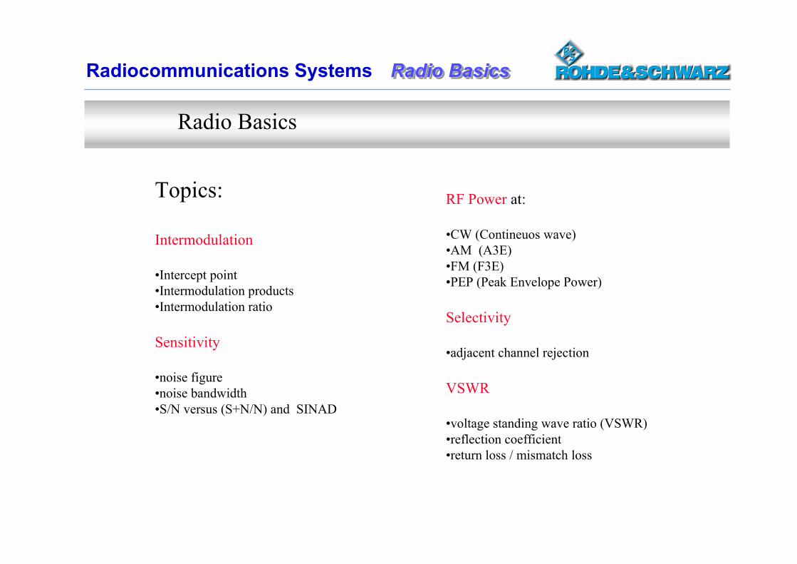
Topics:
Intermodulation
•Intercept point•Intermodulation products •Intermodulation ratio
Sensitivity
•noise figure•noise bandwidth•S/N versus (S+N/N) and SINAD
RF Power at:
•CW (Contineuos wave)•AM (A3E)•FM (F3E)•PEP (Peak Envelope Power)
Selectivity
•adjacent channel rejection
VSWR
•voltage standing wave ratio (VSWR) •reflection coefficient•return loss / mismatch loss
Radio Basics
Radio BasicsRadio BasicsRadio BasicsRadiocommunications Systems
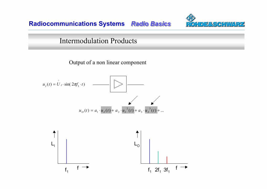
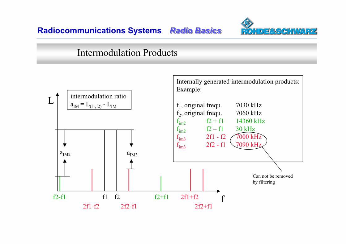
Intermodulation Products
Output of a non linear component
Radio BasicsRadio BasicsRadio BasicsRadiocommunications Systems
L
ff2-f1 f1 f2 f2+f1 2f1+f2 2f1-f2 2f2-f1 2f2+f1
aIM2 aIM3
intermodulation ratio aIM = L(f1,f2) - LIM
Internally generated intermodulation products:Example:
f1, original frequ. 7030 kHzf2, original frequ. 7060 kHzfim2 f2 + f1 14360 kHzfim2 f2 – f1 30 kHzfim3 2f1 - f2 7000 kHzfim3 2f2 - f1 7090 kHz
Can not be removed by filtering
Intermodulation Products
Radio BasicsRadio BasicsRadio BasicsRadiocommunications Systems
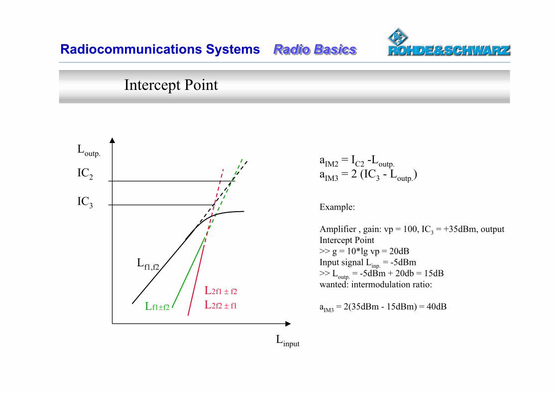
Loutp.
IC2
IC3
Linput
Lf1,f2
Lf1f2
L2f1 f2
L2f2 f1
aIM2 = IC2 -Loutp.aIM3 = 2 (IC3 - Loutp.)
Example:
Amplifier , gain: vp = 100, IC3 = +35dBm, output Intercept Point>> g = 10*lg vp = 20dBInput signal Linp. = -5dBm>> Loutp. = -5dBm + 20db = 15dB wanted: intermodulation ratio:
aIM3 = 2(35dBm - 15dBm) = 40dB
Intercept Point
Radio BasicsRadio BasicsRadio BasicsRadiocommunications Systems
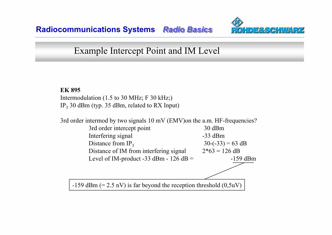
EK 895Intermodulation (1.5 to 30 MHz; F 30 kHz;)IP3 30 dBm (typ. 35 dBm, related to RX Input)
3rd order intermod by two signals 10 mV (EMV)on the a.m. HF-frequencies?3rd order intercept point 30 dBmInterfering signal -33 dBmDistance from IP3 30-(-33) = 63 dBDistance of IM from interfering signal 2*63 = 126 dBLevel of IM-product -33 dBm - 126 dB = -159 dBm
-159 dBm (= 2.5 nV) is far beyond the reception threshold (0,5uV)
Example Intercept Point and IM Level
Radio BasicsRadio BasicsRadio BasicsRadiocommunications Systems
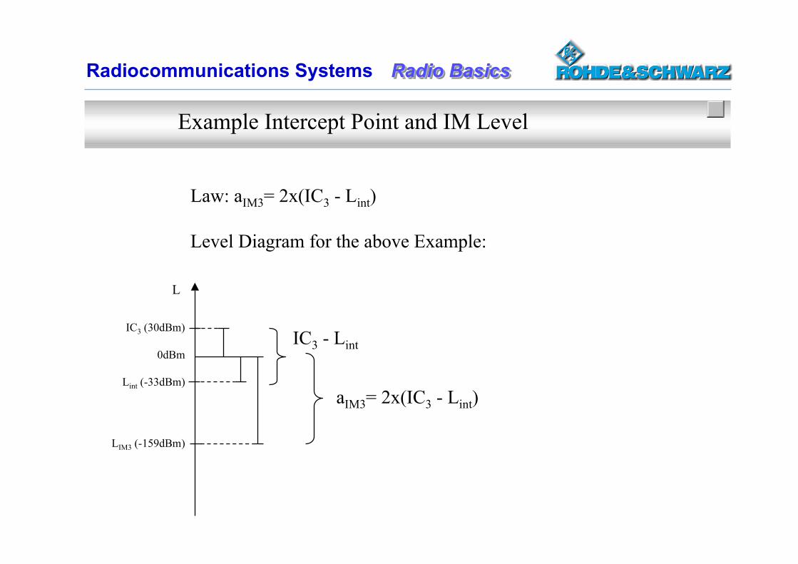
Example Intercept Point and IM Level
Law: aIM3= 2x(IC3 - Lint)
Level Diagram for the above Example:
L
IC3 (30dBm)
0dBm
Lint (-33dBm)
LIM3 (-159dBm)
IC3 - Lint
aIM3= 2x(IC3 - Lint)
Radio BasicsRadio BasicsRadio BasicsRadiocommunications Systems
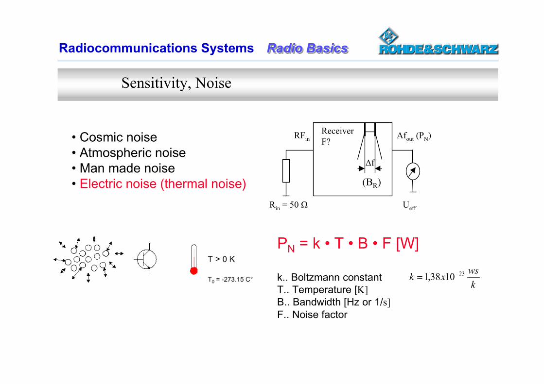
Sensitivity, Noise
PN = k • T • B • F [W]
k.. Boltzmann constantT.. Temperature [K]B.. Bandwidth [Hz or 1/s]F.. Noise factor
kwsxk 231038,1
Rin = 50 Ω
ReceiverF?
Ueff
∆f
Afout (PN)RFin
(BR)
• Cosmic noise• Atmospheric noise• Man made noise• Electric noise (thermal noise)
Radio BasicsRadio BasicsRadio BasicsRadiocommunications Systems
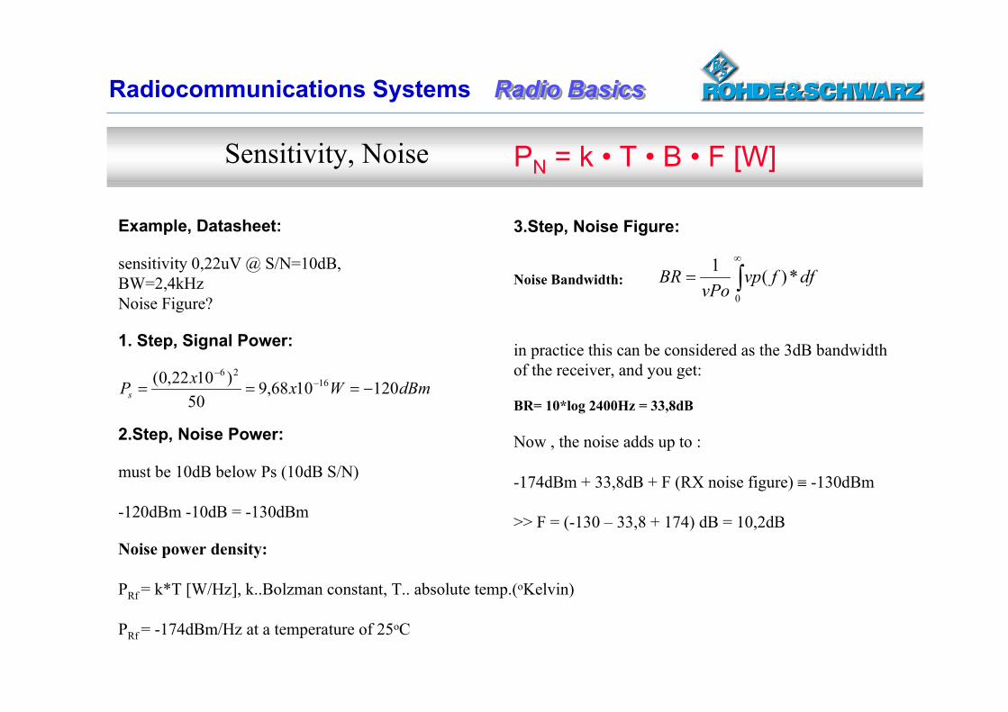
Example, Datasheet:
sensitivity 0,22uV @ S/N=10dB, BW=2,4kHzNoise Figure?
1. Step, Signal Power:
3.Step, Noise Figure:
Noise Bandwidth:
in practice this can be considered as the 3dB bandwidth of the receiver, and you get:
BR= 10*log 2400Hz = 33,8dB
Now , the noise adds up to :
-174dBm + 33,8dB + F (RX noise figure) -130dBm
>> F = (-130 – 33,8 + 174) dB = 10,2dB
0
*)(1 dffvpvPo
BR
Sensitivity, Noise
dBmWxxPs 1201068,950
)1022,0( 1626
2.Step, Noise Power:
must be 10dB below Ps (10dB S/N)
-120dBm -10dB = -130dBm
Noise power density:
PRf = k*T [W/Hz], k..Bolzman constant, T.. absolute temp.(oKelvin)
PRf = -174dBm/Hz at a temperature of 25oC
PN = k • T • B • F [W]
Radio BasicsRadio BasicsRadio BasicsRadiocommunications Systems
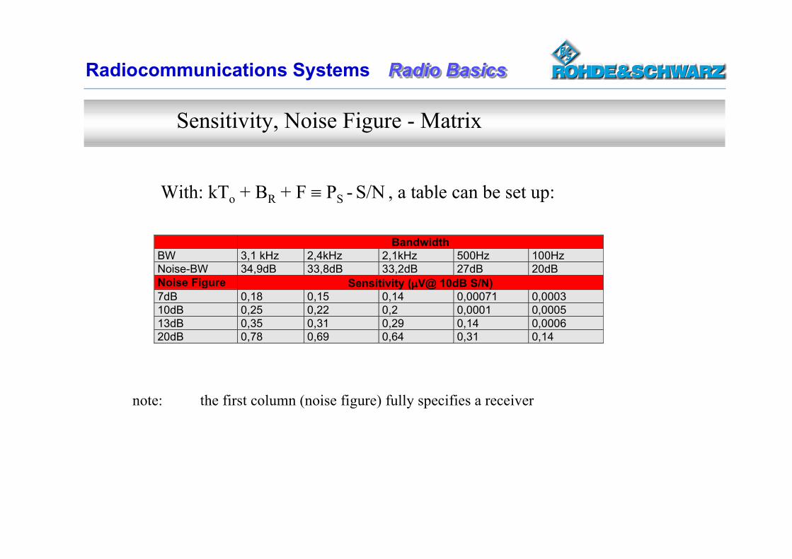
Sensitivity, Noise Figure - Matrix
With: kTo + BR + F PS - S/N , a table can be set up:
BandwidthBW 3,1 kHz 2,4kHz 2,1kHz 500Hz 100HzNoise-BW 34,9dB 33,8dB 33,2dB 27dB 20dBNoise Figure Sensitivity (V@ 10dB S/N)7dB 0,18 0,15 0,14 0,00071 0,000310dB 0,25 0,22 0,2 0,0001 0,000513dB 0,35 0,31 0,29 0,14 0,000620dB 0,78 0,69 0,64 0,31 0,14
note: the first column (noise figure) fully specifies a receiver
Radio BasicsRadio BasicsRadio BasicsRadiocommunications Systems
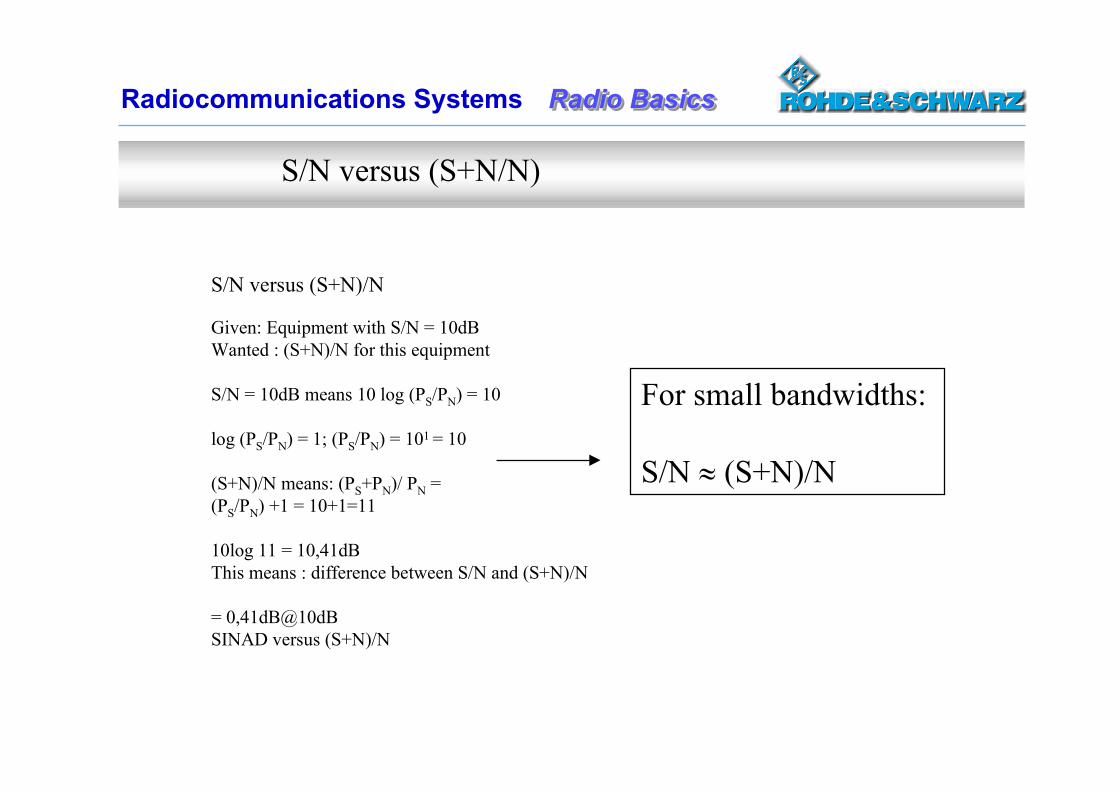
S/N versus (S+N/N)
S/N versus (S+N)/N
Given: Equipment with S/N = 10dBWanted : (S+N)/N for this equipment
S/N = 10dB means 10 log (PS/PN) = 10
log (PS/PN) = 1; (PS/PN) = 101 = 10
(S+N)/N means: (PS+PN)/ PN = (PS/PN) +1 = 10+1=11
10log 11 = 10,41dBThis means : difference between S/N and (S+N)/N
= 0,41dB@10dB SINAD versus (S+N)/N
For small bandwidths:
S/N (S+N)/N
Radio BasicsRadio BasicsRadio BasicsRadiocommunications Systems
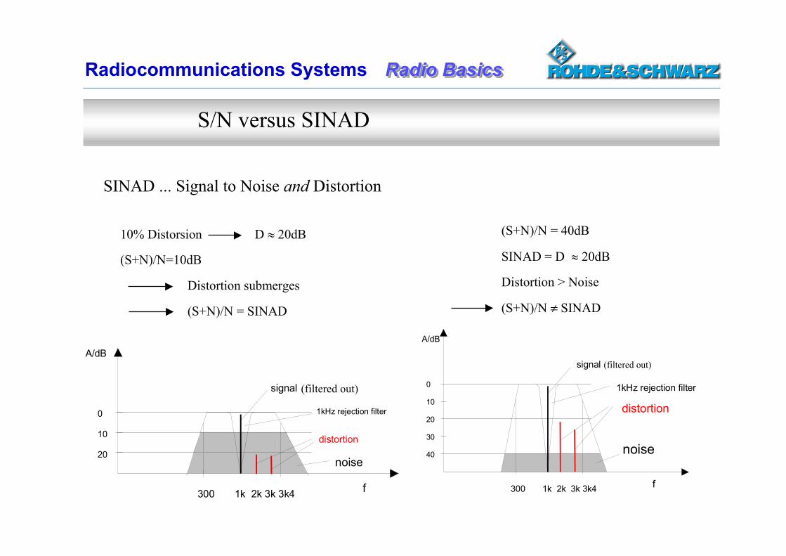
S/N versus SINAD
(S+N)/N = 40dB
SINAD = D 20dB
Distortion > Noise
(S+N)/N SINAD
0
10
20
30
40
A/dB
f300 1k 2k 3k 3k4
signal
distortion
1kHz rejection filter
noise
10% Distorsion D 20dB
(S+N)/N=10dB
Distortion submerges
(S+N)/N = SINAD
f300 1k 2k 3k 3k4
signal
distortion
1kHz rejection filter
A/dB
0
10
20noise
SINAD ... Signal to Noise and Distortion
(filtered out)
(filtered out)
Radio BasicsRadio BasicsRadio BasicsRadiocommunications Systems
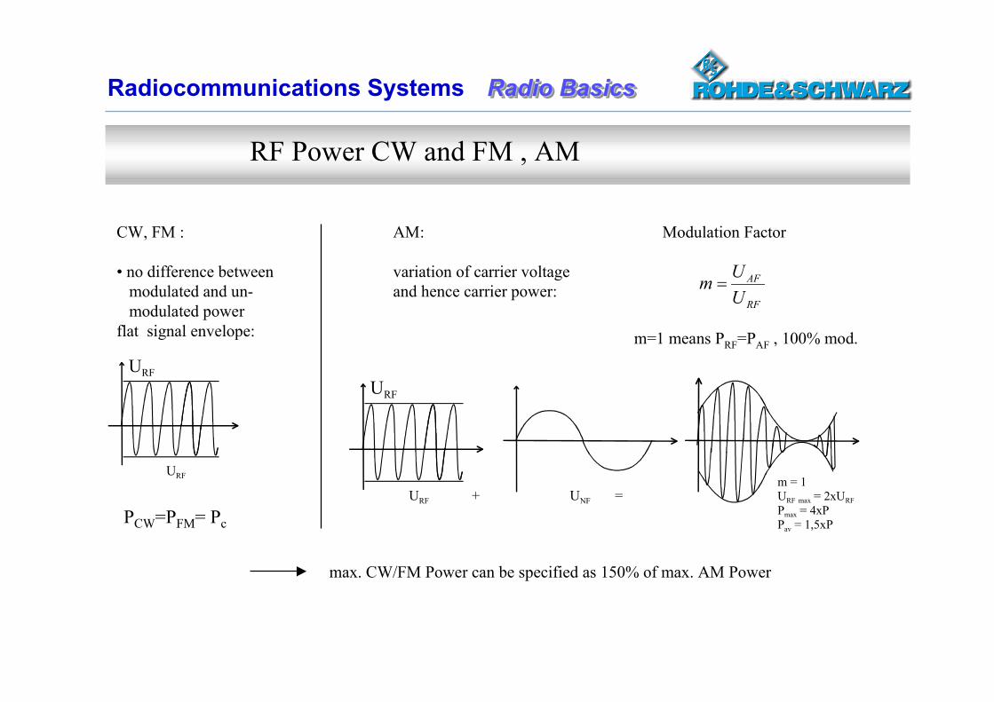
RF Power CW and FM , AM
CW, FM :
• no difference between modulated and un- modulated powerflat signal envelope:
AM:
variation of carrier voltage and hence carrier power:
URF
URF + UNF =m = 1URF max = 2xURFPmax = 4xPPav = 1,5xP
RF
AF
UUm
URF
URF
PCW=PFM= Pc
Modulation Factor
m=1 means PRF=PAF , 100% mod.
max. CW/FM Power can be specified as 150% of max. AM Power
Radio BasicsRadio BasicsRadio BasicsRadiocommunications Systems
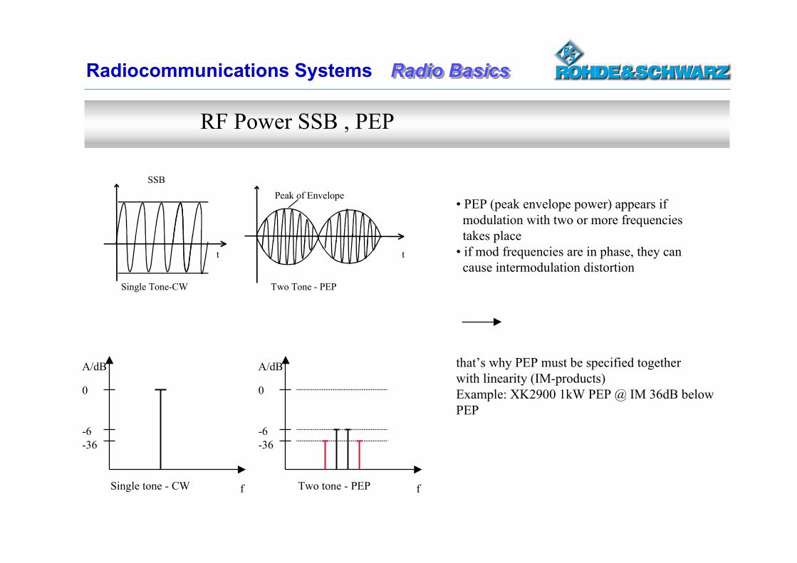
RF Power SSB , PEP
SSBPeak of Envelope
Single Tone-CW Two Tone - PEP
t t
A/dB
0
-6-36
f
A/dB
0
-6-36
fSingle tone - CW Two tone - PEP
• PEP (peak envelope power) appears if modulation with two or more frequencies takes place • if mod frequencies are in phase, they can cause intermodulation distortion
that’s why PEP must be specified togetherwith linearity (IM-products)Example: XK2900 1kW PEP @ IM 36dB belowPEP
Radio BasicsRadio BasicsRadio BasicsRadiocommunications Systems
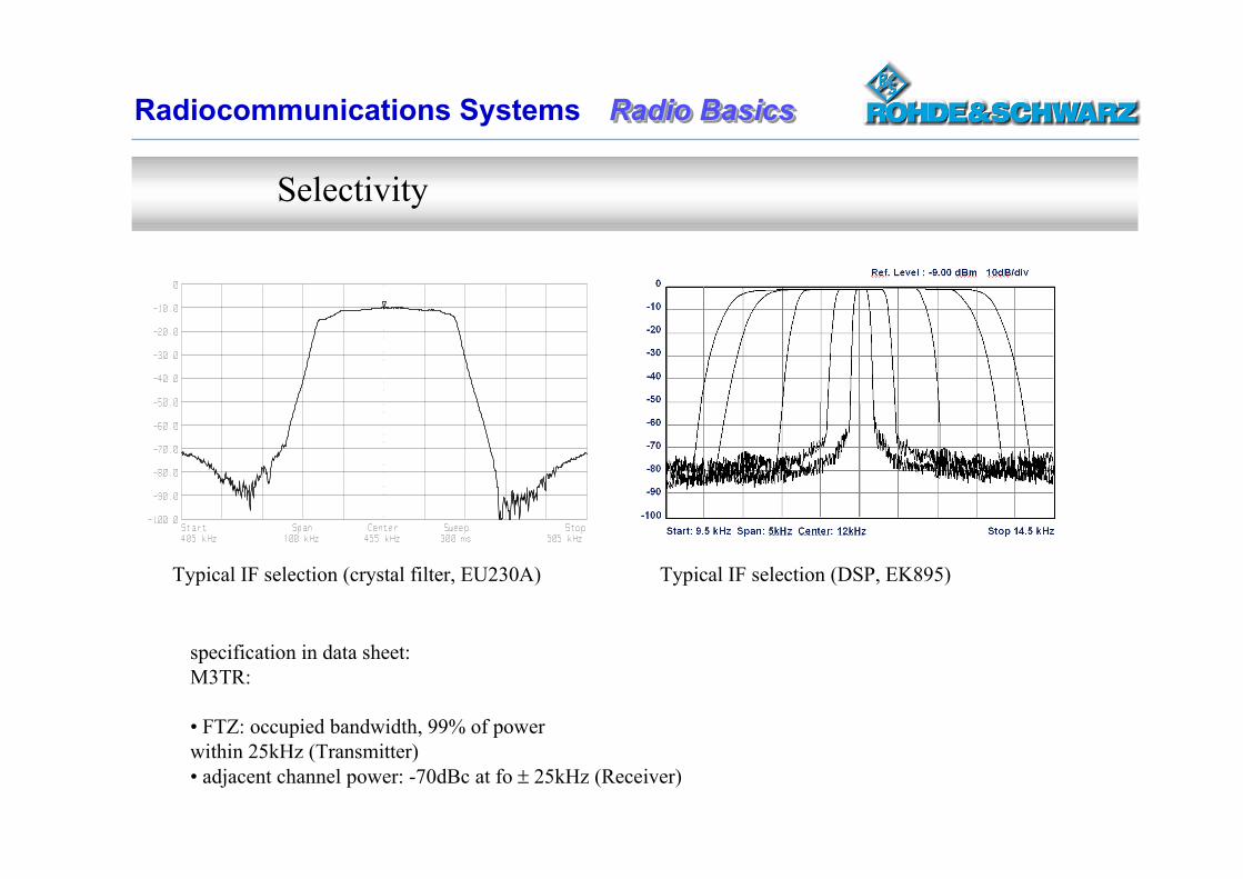
Selectivity
specification in data sheet:M3TR:
• FTZ: occupied bandwidth, 99% of powerwithin 25kHz (Transmitter)• adjacent channel power: -70dBc at fo 25kHz (Receiver)
Typical IF selection (crystal filter, EU230A) Typical IF selection (DSP, EK895)
Radio BasicsRadio BasicsRadio BasicsRadiocommunications Systems
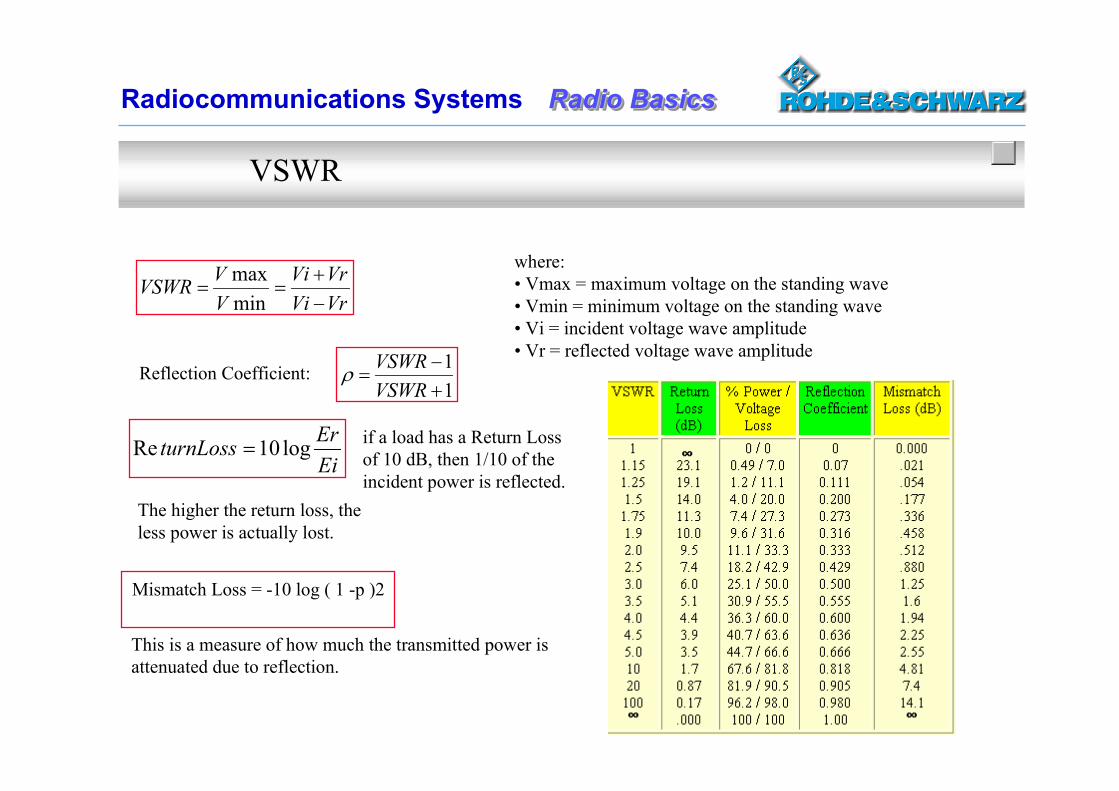
VSWR
where: • Vmax = maximum voltage on the standing wave• Vmin = minimum voltage on the standing wave• Vi = incident voltage wave amplitude• Vr = reflected voltage wave amplitude
VrViVrVi
VVVSWR
minmax
Reflection Coefficient:11
VSWRVSWR
EiErturnLoss log10Re
if a load has a Return Loss of 10 dB, then 1/10 of the incident power is reflected.
This is a measure of how much the transmitted power is attenuated due to reflection.
Mismatch Loss = -10 log ( 1 -p )2
The higher the return loss, theless power is actually lost.
Radio BasicsRadio BasicsRadio BasicsRadiocommunications Systems
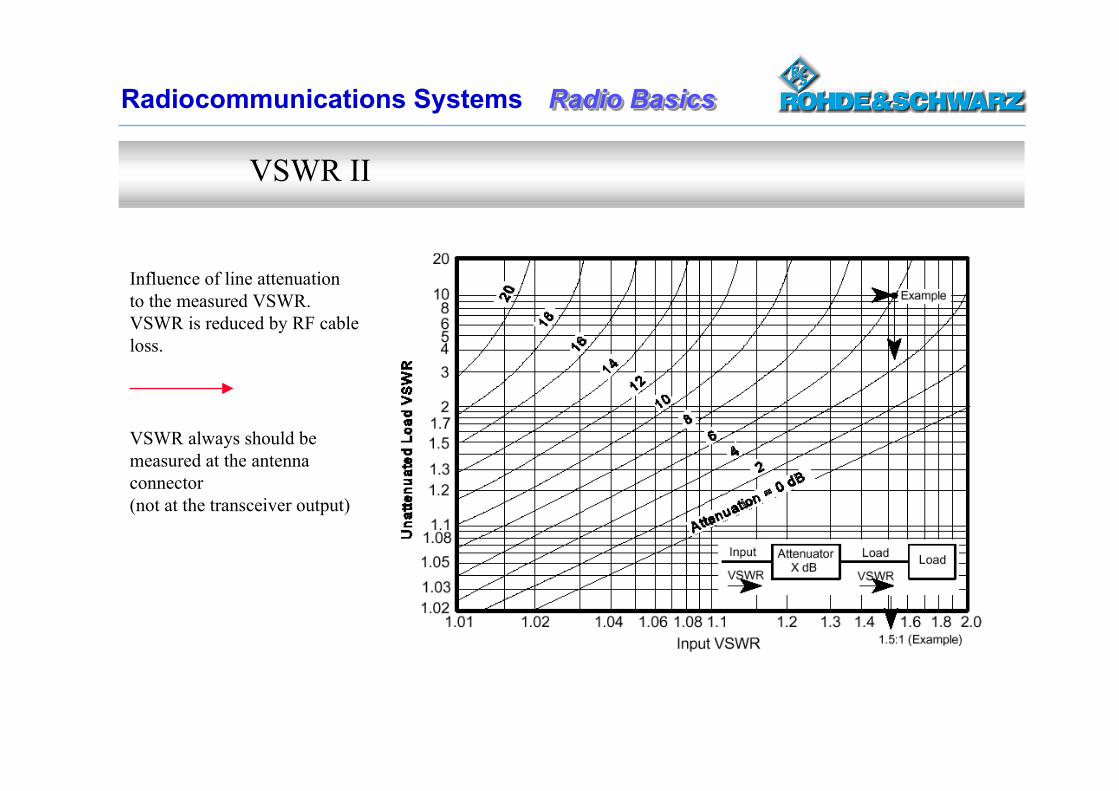
VSWR II
Influence of line attenuationto the measured VSWR.VSWR is reduced by RF cableloss.
VSWR always should be measured at the antenna connector(not at the transceiver output)
Radio BasicsRadio BasicsRadio BasicsRadiocommunications Systems
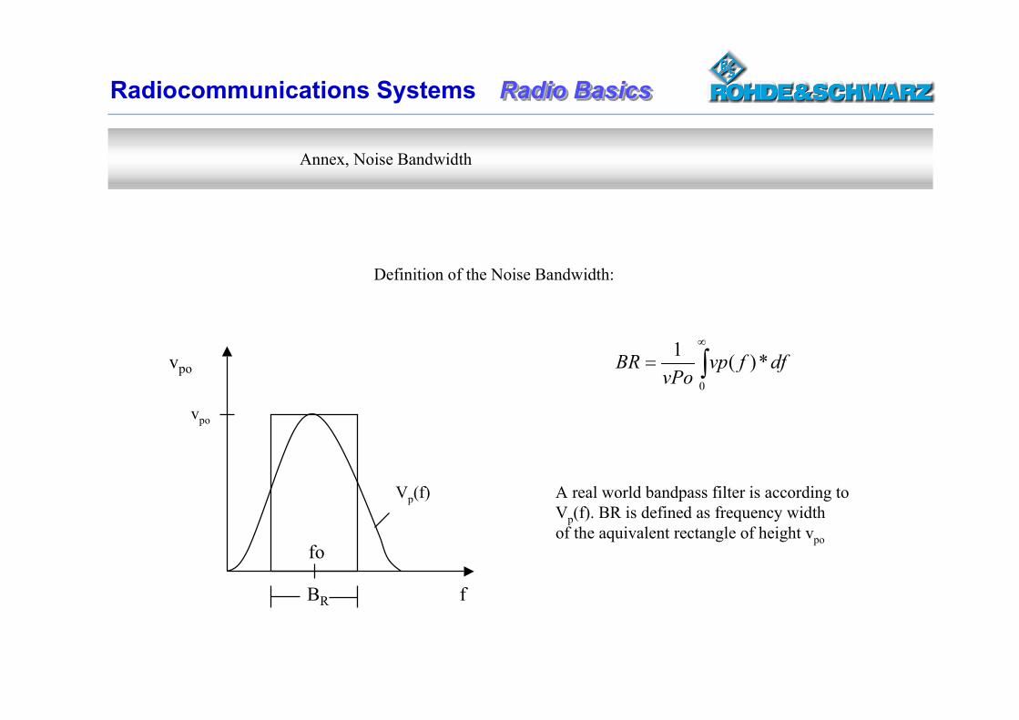
Annex, Noise Bandwidth
Definition of the Noise Bandwidth:
0
*)(1 dffvpvPo
BR
A real world bandpass filter is according toVp(f). BR is defined as frequency widthof the aquivalent rectangle of height vpo
vpo
f
fo
BR
Vp(f)
vpo