Embed Size (px)
Citation preview
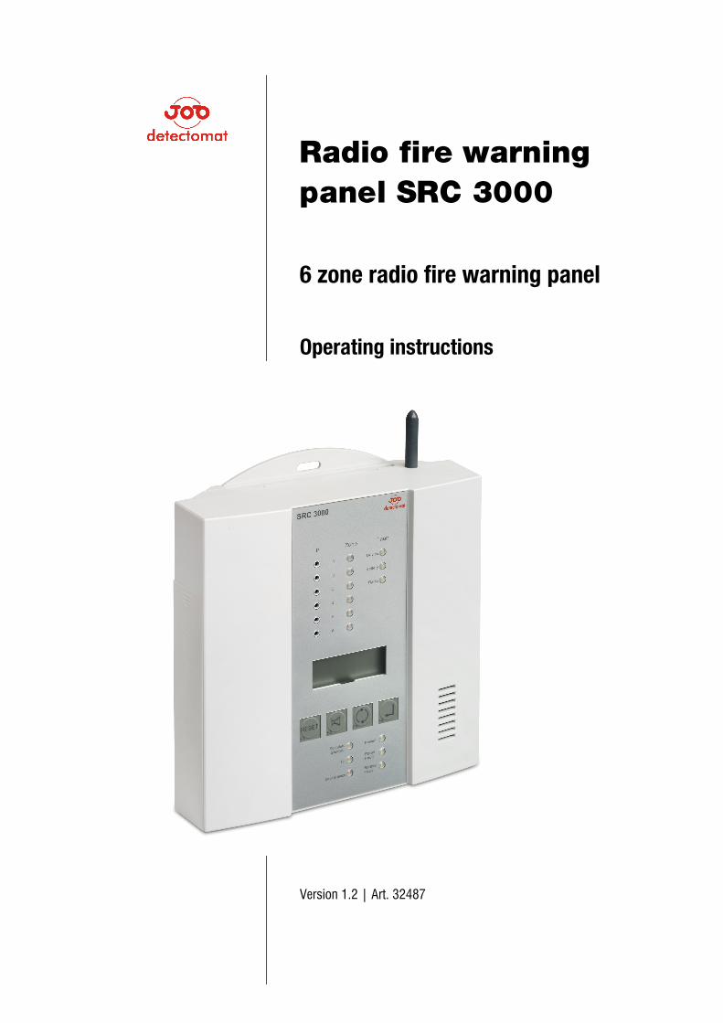
Radio fire warning panel SRC 3000 6 zone radio fire warning panel
Operating instructions
Version 1.2 | Art. 32487

detectomat GmbH Headquarter: Phone: +49 (0) 4102-2114-60 An der Strusbek 5 Fax: +49 (0) 4102-2114-670 D – 22926 Ahrensburg Hotline: Phone: Please see www.detectomat.com Fax: +49 (0) 4102-2114-9670 Manual no. 53438 Version 1.2 - 02 August 2011
* Please specify your customer number when contacting the hotline!
Contents
Version 1.2 3
Contents
1 Explanation of Operating Instructions ................................................. 5
1.1 Purpose of Operating Instructions ..................................................................................... 5 1.2 Notes on Operating Instructions ........................................................................................ 5 1.3 Further Documentation ..................................................................................................... 5
2 General Safety Instructions .................................................................. 6
2.1 Intended Use .................................................................................................................... 6 2.2 Requirements to be met by operator/installer.................................................................... 6
3 Product Information .............................................................................. 7
3.1 Summary .......................................................................................................................... 7 3.2 Environmental conditions .................................................................................................. 7 3.3 Technical data .................................................................................................................. 8 3.4 Conformity ........................................................................................................................ 9 3.5 Software version / serial number ...................................................................................... 9 3.6 SRC 3000 Radio fire warning panel ................................................................................ 10
3.6.1 Function ............................................................................................................ 10 3.6.2 Control and indicating elements ........................................................................ 10
3.7 Radio module 433 bidirectional ...................................................................................... 12 3.7.1 Function ............................................................................................................ 12 3.7.2 Control and indicating elements ........................................................................ 12
3.8 Radio Repeater SRC 3000 .............................................................................................. 12 3.8.1 Function ............................................................................................................ 12 3.8.2 Control and indicating elements ........................................................................ 13
3.9 Radio device ................................................................................................................... 14
4 Installation .......................................................................................... 16
4.1 Installation of the radio fire warning panel SRC 3000 ...................................................... 16 4.2 Installation of the 433 bidirectional radio module ............................................................ 17 4.3 Installation of the radio repeater ..................................................................................... 17
5 Logging on radio devices .................................................................... 18
5.1 Control authorization via PIN code................................................................................... 18 5.1.1 Entering the PIN code ........................................................................................ 19 5.1.2 Editing the PIN code .......................................................................................... 19
5.2 Logging on a smoke detector fitted with a radio module onto SRC 3000 panel ................ 19 5.2.1 Minimising errors during the login process ........................................................ 21 5.2.2 Deactivation of acoustic signalling on a smoke detector fitted with a radio module
......................................................................................................................... 21 5.2.3 Re-activation of acoustic signalling on smoke detectors fitted with a radio module
......................................................................................................................... 21 5.3 Procedure if radio repeater is used ................................................................................. 22
5.3.1 Logging on the repeater to the SRC 3000 panel ................................................. 22 5.3.2 Logging on smoke detectors fitted with radio modules onto the SRC 3000 panel
......................................................................................................................... 23 5.3.3 Logging on radio devices fitted with a radio module onto the radio repeater ...... 23
6 Deleting radio devices ........................................................................ 25
6.1 Deleting radio device directly from the SRC 3000 radio fire warning panel ...................... 25
Contents
Version 1.2 4
6.2 Deleting radio devices operated via a radio repeater ....................................................... 25 6.2.1 Deleting a radio module from the radio repeater ................................................ 26
6.3 Deleting a radio repeater from the SCR 3000 fire warning panel ..................................... 26 6.4 Reset .............................................................................................................................. 27
6.4.1 Performing a reset on smoke detector fitted with a radio module ....................... 27 6.4.2 Performing a general reset on the radio repeater ............................................... 27 6.4.3 Performing a general reset on the SRC 3000 panel ............................................ 27
7 Configuration ....................................................................................... 28
7.1 Configuration of the SRC 3000 panel .............................................................................. 28 7.1.1 Assigning relays to zones .................................................................................. 28 7.1.2 Programming a relay for a "Radio Device Fault" ................................................ 28 7.1.3 Programming a relay a "SRC 3000 panel fault" ................................................. 29 7.1.4 Programming relays for a common alarm .......................................................... 29 7.1.5 Programming relays for a common fault ............................................................ 30 7.1.6 Programming the relay outputs from steady to pulsed ....................................... 30 7.1.7 Relay configuration ............................................................................................ 31 7.1.8 Programming overview table for sections 7.1.1 to 7.1.7 .................................... 32
7.2 PIN configuration for the SUB-D connector ...................................................................... 32 7.3 Special configurations .................................................................................................... 33
7.3.1 Parameter 1 ...................................................................................................... 33 7.3.2 Parameter 2 ...................................................................................................... 33 7.3.3 Parameter 3 ...................................................................................................... 33 7.3.4 Parameter 4 ...................................................................................................... 33
8 Commissioning .................................................................................... 34
8.1 Functionality tests .......................................................................................................... 34 8.1.1 Alarm testing ..................................................................................................... 34 8.1.2 Testing the communication signal to the radio repeater ..................................... 35
9 Operation ............................................................................................. 36
9.1 Function keys ................................................................................................................. 36 9.2 Alarms and faults ........................................................................................................... 37
9.2.1 Signalling of alarms and faults ........................................................................... 37 9.2.2 Acknowledging alarm/fault messages ............................................................... 38
10 Maintenance ........................................................................................ 39
10.1 Inspection and maintenance intervals ............................................................................. 39 10.2 Maintenance/Service measures ...................................................................................... 39
10.2.1 Activating/deactivating the service mode ........................................................... 39 10.2.2 Automatic disablement of the inspection mode .................................................. 40
10.3 Cleaning ......................................................................................................................... 40 10.4 Environmental disposal ................................................................................................... 40
Annex 1: List of Abbreviations ...................................................................... 41
Explanation of Operating Instructions
Version 1.2 5
1 Explanation of Operating Instructions
1.1 Purpose of Operating Instructions These operating instructions are intended for technically qualified individuals who have been
trained in commissioning, operation, maintenance and repair of the SRC 3000 radio fire warning
panel.
The user is obliged to comply with these operating instructions, particularly section
"2 Instructions” on Page 6. These operating instructions contain all relevant technical information
required for operating the SRC 3000 radio fire warning panel properly, efficiently and safely.
1.2 Notes on Operating Instructions The following conventions are used in these operating instructions:
• Lists marked with dots contain information, not working steps.
• Numbered lists describe a sequence of working steps or hierarchically organized information.
• Keyboard commands are shown in square brackets, e.g. [Reset].
The following pictograms are used in these operating instructions. They indicate hazards,
warnings and important notes. These pictograms must be noted in any case.
Warning! Risk of electric shock.
Disconnect 230 V power supply before working on live connections.
The user is informed about situations and procedures which might result in injuries or
even death.
Warning!
The user is informed about situations and procedures which might result in injuries
and/or equipment damage and economic loss.
Warning!
The user is informed about precautions to be taken when handling electrostatic
sensitive components.
Note!
The user is informed on how to use the product.
1.3 Further Documentation The present operating instructions describe all procedures required for installation, configuration,
commissioning, operation, maintenance and repair of the SRC 3000 radio fire warning panel.
For further information, refer to the following documents:
• Operating instructions of radio devices
• Design of radio smoke warning detectors: DIN 14676
General Safety Instructions
Version 1.2 6
2 General Safety Instructions
The SRC 3000 radio fire warning panel is designed to be state of the art within the applicable
safety regulations.
Non-compliance and wrong installation, commissioning, operation, maintenance, repair or misuse
might:
• present a hazard to life and limb of users or others
• cause damage to the SRC 3000 radio fire warning panel and other equipment
• prevent efficient use of the SRC 3000 radio fire warning panel
2.1 Intended Use The SRC 3000 radio fire warning panel is only intended for acquisition, evaluation, display and
transmission of measured values detected by the radio devices.
The radio repeater is only intended for extending and monitoring the radio range between the SRC
3000 radio fire warning panel and the radio devices and for transmission of the values measured
by the detectors/modules.
Proper use also includes:
• compliance with the safety instructions included in these operating instructions
• compliance with the maintenance and repair instructions
• use of lithium batteries for the radio devices
Any other use shall be considered as not in compliance with the "Intended Use".
detectomat GmbH shall not be held liable for any damage or losses resulting from any use of the
SRC 3000 radio fire warning panel which is not in compliance with the Intended Use.
2.2 Requirements to be met by operator/installer Installation, commissioning, maintenance and repair of the SRC 3000 radio fire warning panel may
only be carried out by companies which have verified that they have the necessary technical skills.
Product Information
Version 1.2 7
3 Product Information
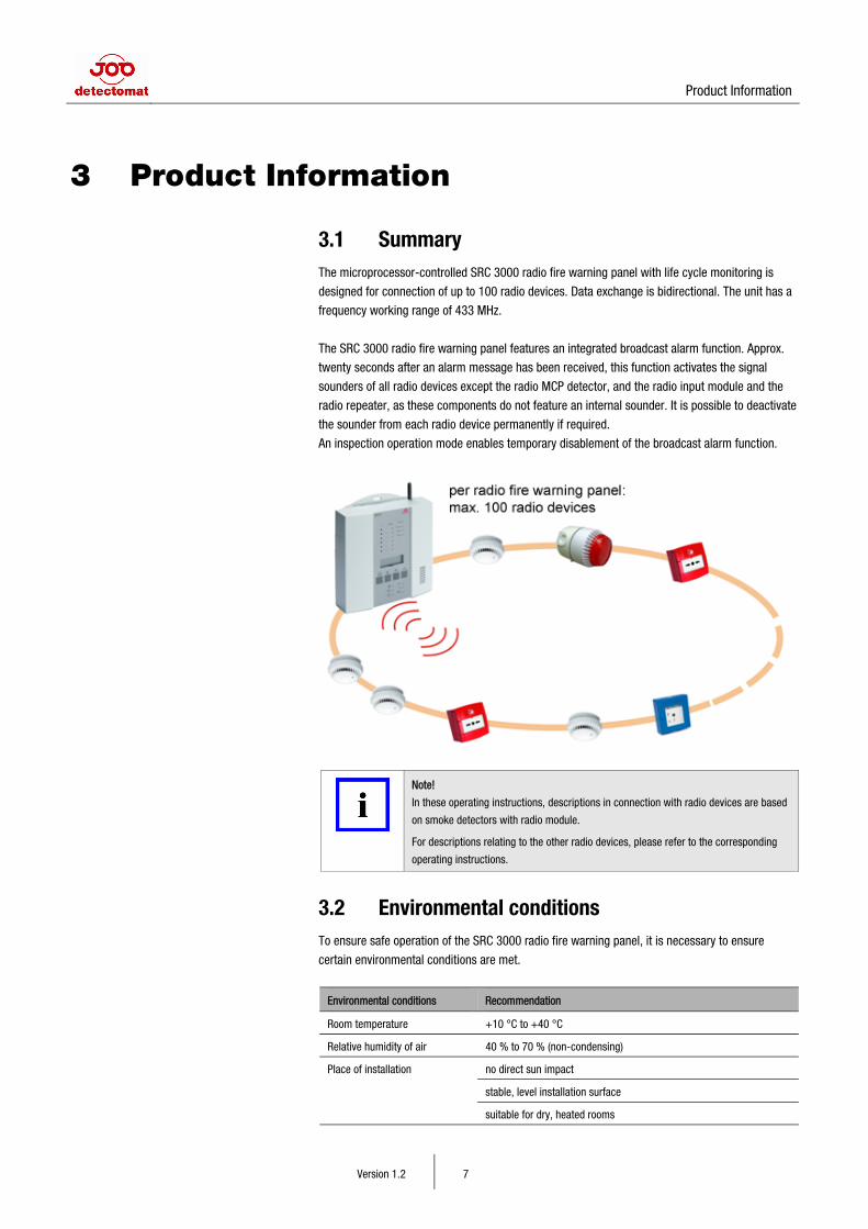
3.1 Summary The microprocessor-controlled SRC 3000 radio fire warning panel with life cycle monitoring is
designed for connection of up to 100 radio devices. Data exchange is bidirectional. The unit has a
frequency working range of 433 MHz.
The SRC 3000 radio fire warning panel features an integrated broadcast alarm function. Approx.
twenty seconds after an alarm message has been received, this function activates the signal
sounders of all radio devices except the radio MCP detector, and the radio input module and the
radio repeater, as these components do not feature an internal sounder. It is possible to deactivate
the sounder from each radio device permanently if required.
An inspection operation mode enables temporary disablement of the broadcast alarm function.
Note!
In these operating instructions, descriptions in connection with radio devices are based
on smoke detectors with radio module.
For descriptions relating to the other radio devices, please refer to the corresponding
operating instructions.
3.2 Environmental conditions To ensure safe operation of the SRC 3000 radio fire warning panel, it is necessary to ensure
certain environmental conditions are met.
Environmental conditions Recommendation
Room temperature +10 °C to +40 °C
Relative humidity of air 40 % to 70 % (non-condensing)
Place of installation no direct sun impact
stable, level installation surface
suitable for dry, heated rooms
Product Information
Version 1.2 8
no small or cramped rooms (to prevent radio echo)
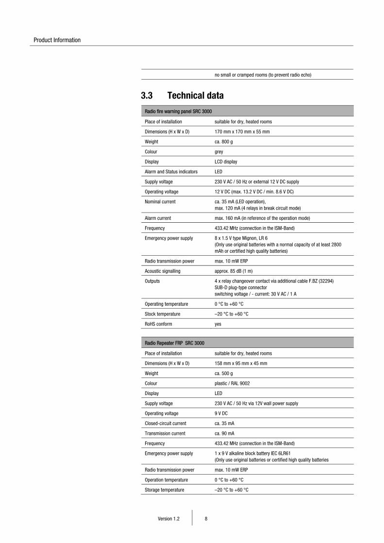
3.3 Technical data
Radio fire warning panel SRC 3000
Place of installation suitable for dry, heated rooms
Dimensions (H x W x D) 170 mm x 170 mm x 55 mm
Weight ca. 800 g
Colour grey
Display LCD display
Alarm and Status indicators LED
Supply voltage 230 V AC / 50 Hz or external 12 V DC supply
Operating voltage 12 V DC (max. 13.2 V DC / min. 8.6 V DC)
Nominal current ca. 35 mA (LED operation), max. 120 mA (4 relays in break circuit mode)
Alarm current max. 160 mA (in reference of the operation mode)
Frequency 433.42 MHz (connection in the ISM-Band)
Emergency power supply 8 x 1.5 V type Mignon, LR 6 (Only use original batteries with a normal capacity of at least 2800 mAh or certified high quality batteries)
Radio transmission power max. 10 mW ERP
Acoustic signalling approx. 85 dB (1 m)
Outputs 4 x relay changeover contact via additional cable F.BZ (32294) SUB-D plug-type connector switching voltage / - current: 30 V AC / 1 A
Operating temperature 0 °C to +60 °C
Stock temperature –20 °C to +60 °C
RoHS conform yes
Radio Repeater FRP SRC 3000
Place of installation suitable for dry, heated rooms
Dimensions (H x W x D) 158 mm x 95 mm x 45 mm
Weight ca. 500 g
Colour plastic / RAL 9002
Display LED
Supply voltage 230 V AC / 50 Hz via 12V wall power supply
Operating voltage 9 V DC
Closed-circuit current ca. 35 mA
Transmission current ca. 90 mA
Frequency 433.42 MHz (connection in the ISM-Band)
Emergency power supply 1 x 9 V alkaline block battery IEC 6LR61 (Only use original batteries or certified high quality batteries
Radio transmission power max. 10 mW ERP
Operation temperature 0 °C to +60 °C
Storage temperature –20 °C to +60 °C
Product Information
Version 1.2 9
Enclosure type IP 20
RoHS conform yes
Radio module FM SRC 3000
Operating voltage 9 V DC
Nominal current ca. 40 μA
Transmission current ca. 40 mA
Frequency 433.42 MHz (connection in the ISM-Band)
Radio transmission power max. 10 mW ERP
Operation temperature 0 °C to +55 °C
Storage temperature –20 °C to +60 °C
RoHS conform yes
Radio smoke detector
Dimensions (H x Ø) 51 mm (including base) x 100 mm
Operating voltage 9 V DC Note: Lithium ions batteries are recommended for use with radio modules.
Closed-circuit current < 16 μA
Response sensitivity < 0.15 dB/m
Air velocity max. 20 m/s
Acoustic signalling ca. 85 dB (1 m)
Nominal temperature –10 °C to +60 °C
Humidity of air max. 90 % RH non-condensing
Interfaces for radio module FM
Enclosure type IP 30
RoHS conform yes
3.4 Conformity If used as per the Intended Use, the SRC 3000 radio fire warning panel meets the requirements of
the R&TTE Directive (1999/5/EC).
3.5 Software version / serial number To display the software version and the serial number of the SRC 3000 radio fire warning panel,
proceed as follows:
1 Press function keys [F1] and [F4] at the same time until the software version (e.g. 242) is
displayed.
If you keep the two keys pressed, after a while the serial number will be displayed instead of
the software version.
Product Information
Version 1.2 10
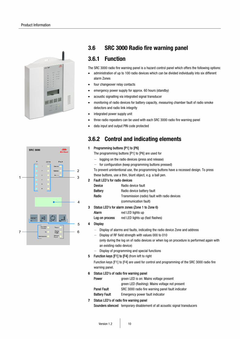
3.6 SRC 3000 Radio fire warning panel
3.6.1 Function The SRC 3000 radio fire warning panel is a hazard control panel which offers the following options:
• administration of up to 100 radio devices which can be divided individually into six different
alarm Zones
• four changeover relay contacts
• emergency power supply for approx. 60 hours (standby)
• acoustic signalling via integrated signal transducer
• monitoring of radio devices for battery capacity, measuring chamber fault of radio smoke
detectors and radio link integrity
• integrated power supply unit
• three radio repeaters can be used with each SRC 3000 radio fire warning panel
• data input and output PIN code protected
3.6.2 Control and indicating elements 1 Programming buttons [P1] to [P6]
The programming buttons [P1] to [P6] are used for
− logging on the radio devices (press and release)
− for configuration (keep programming buttons pressed)
To prevent unintentional use, the programming buttons have a recessed design. To press
these buttons, use a thin, blunt object, e.g. a ball pen.
2 Fault LED’s for radio devices
Device Radio device fault
Battery Radio device battery fault
Radio Transmission (radio) fault with radio devices
(communication fault)
3 Status LED’s for alarm zones (Zone 1 to Zone 6)
Alarm red LED lights up
Log-on process red LED lights up (fast flashes)
4 Display
− Display of alarms and faults, indicating the radio device Zone and address
− Display of RF field strength with values 000 to 010
(only during the log on of radio devices or when log on procedure is performed again with
an existing radio device)
− Display of programming and special functions
5 Function keys [F1] to [F4] (from left to right
Function keys [F1] to [F4] are used for control and programming of the SRC 3000 radio fire
warning panel.
6 Status LED’s of radio fire warning panel
Power green LED is on: Mains voltage present
green LED (flashing): Mains voltage not present
Panel Fault SRC 3000 radio fire warning panel fault indicator
Battery Fault Emergency power fault indicator
7 Status LED’s of radio fire warning panel
Sounders silenced temporary disablement of all acoustic signal transducers
Product Information
Version 1.2 11
Tx SRC 3000 radio fire warning panel is in
broadcast mode
Maintenance inspection mode is active; broadcast of alarms is disabled
Programming buttons
[P1] Special configuration
For more information, refer to section ”7.3 Special configurations” on Page 33.
Select alarm zone 1
Log on a radio device onto the SRC 3000 radio fire warning panel.
For more information, refer to section 5.2 on Page 19.
[P2] Select alarm zone 2
Log on a radio device onto the SRC 3000 radio fire warning panel.
For more information, refer to section 5.2 on Page 19.
[P3] Relay assignment
For more information, refer to section "7.1 Configuration of the SRC 3000 panel" on Page 28.
Select alarm zone 3
Log on a radio device onto the SRC 3000 radio fire warning panel.
For more information, refer to section 5.2 on Page 19.
[P4] Set PIN code
For more information, refer to section "5.1.2 Editing the PIN code" on Page 19.
Select alarm zone 4
Log on a radio device onto the SRC 3000 radio fire warning panel.
For more information, refer to section 5.2 on Page 19.
[P5] Inspection mode
For more information, refer to section "10.2.1 Activating/deactivating the service mode" on Page 39.
Select alarm zone 5
Log on a radio device onto the SRC 3000 radio fire warning panel.
For more information, refer to section 5.2 on Page 19.
[P6] Select alarm zone 6
Log on a repeater onto the SRC 3000 radio fire warning panel.
For more information, refer to section 5.3.1 on Page 22.
or
Log on a radio device onto the SRC 3000 radio fire warning panel.
For more information, refer to section 5.2 on Page 19.
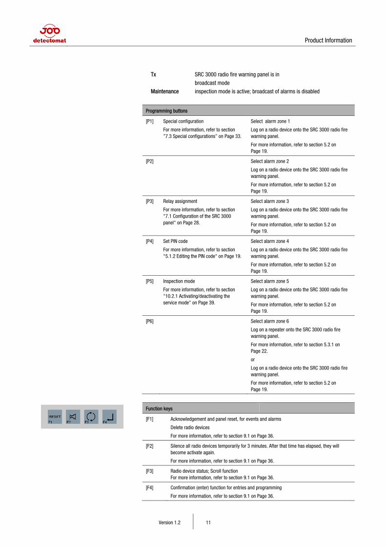
Function keys
[F1] Acknowledgement and panel reset, for events and alarms
Delete radio devices
For more information, refer to section 9.1 on Page 36.
[F2] Silence all radio devices temporarily for 3 minutes. After that time has elapsed, they will become activate again.
For more information, refer to section 9.1 on Page 36.
[F3] Radio device status; Scroll function For more information, refer to section 9.1 on Page 36.
[F4] Confirmation (enter) function for entries and programming
For more information, refer to section 9.1 on Page 36.
Product Information
Version 1.2 12
3.7 Radio module 433 bidirectional
3.7.1 Function The radio module for use in smoke detectors is used for transmitting alarms and faults to the SRC
3000 radio fire warning panel. When a radio device goes into alarm the signal is transmitted to the
SRC 3000 panel, which broadcasts the alarm condition to other radio devices and triggers the
acoustic alarm in the radio smoke detector. Data exchange is bidirectional (broadcast alarm
function).
The acoustic signals for received alarms of individual radio devices with radio module can also be
deactivated separately at the radio module. For more information, refer to section: "5.2.2
Deactivation of acoustic signalling on a smoke detector fitted with a radio module" on Page 21.
The following functions are available:
• Transmission of radio integrity telegrams to the SRC 3000 radio fire warning panel to monitor
the function.
• Display the signal strength from the radio smoke detector during the log on process to the
SRC 3000 radio fire warning panel.
• Transmission of faults from radio smoke detectors and battery replacement signals to the SRC
3000 radio fire warning panel after a plausibility check.
• Individually adjustable acoustic signals indicating receipt of alarms.
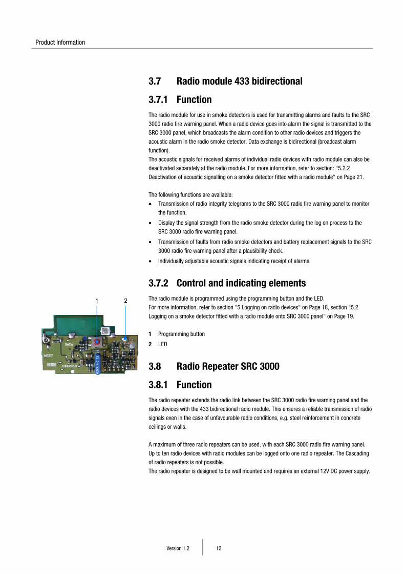
3.7.2 Control and indicating elements The radio module is programmed using the programming button and the LED.
For more information, refer to section "5 Logging on radio devices" on Page 18, section "5.2
Logging on a smoke detector fitted with a radio module onto SRC 3000 panel" on Page 19.
1 Programming button
2 LED
3.8 Radio Repeater SRC 3000
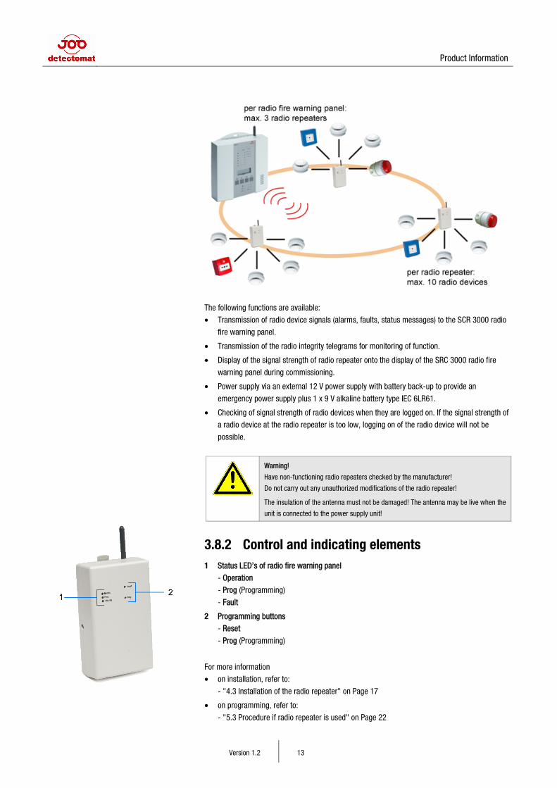
3.8.1 Function The radio repeater extends the radio link between the SRC 3000 radio fire warning panel and the
radio devices with the 433 bidirectional radio module. This ensures a reliable transmission of radio
signals even in the case of unfavourable radio conditions, e.g. steel reinforcement in concrete
ceilings or walls.
A maximum of three radio repeaters can be used, with each SRC 3000 radio fire warning panel.
Up to ten radio devices with radio modules can be logged onto one radio repeater. The Cascading
of radio repeaters is not possible.
The radio repeater is designed to be wall mounted and requires an external 12V DC power supply.
Product Information
Version 1.2 13
The following functions are available:
• Transmission of radio device signals (alarms, faults, status messages) to the SCR 3000 radio
fire warning panel.
• Transmission of the radio integrity telegrams for monitoring of function.
• Display of the signal strength of radio repeater onto the display of the SRC 3000 radio fire
warning panel during commissioning.
• Power supply via an external 12 V power supply with battery back-up to provide an
emergency power supply plus 1 x 9 V alkaline battery type IEC 6LR61.
• Checking of signal strength of radio devices when they are logged on. If the signal strength of
a radio device at the radio repeater is too low, logging on of the radio device will not be
possible.
Warning!
Have non-functioning radio repeaters checked by the manufacturer!
Do not carry out any unauthorized modifications of the radio repeater!
The insulation of the antenna must not be damaged! The antenna may be live when the
unit is connected to the power supply unit!
3.8.2 Control and indicating elements 1 Status LED’s of radio fire warning panel
- Operation
- Prog (Programming)
- Fault
2 Programming buttons
- Reset
- Prog (Programming)
For more information
• on installation, refer to:
- "4.3 Installation of the radio repeater" on Page 17
• on programming, refer to:
- "5.3 Procedure if radio repeater is used" on Page 22
Product Information
Version 1.2 14
- "5.3.3 Logging on radio devices fitted with a radio module onto the radio repeater" on
Page 23
- "5.3.1 Logging on the repeater to the SRC 3000 panel" on Page 22
Buttons Function
[Prog] Start programming
[Reset] Delete radio device; start connection test
LED LED signal Function
LED "Operation" green
On Normal operation
Flashing Mains failure (emergency power supply)
LED "Prog" red Fast flashing/ on
Programming procedure
LED "Fault" yellow flashing low battery
LED "Prog" + LED "Fault"
red + yellow
on Double programming of a radio device
Note!
All radio modules apart from the reset module can be logged onto the radio repeater.
The reset module needs to be logged directly onto the SRC 3000 radio fire warning
panel.
3.9 Radio device The following radio devices can be used with the SRC 3000 panel.
smoke detector HDv 3000 O Note! All designs from the HDv 3000 O range can be used.
art. 30458
underside
top
radio module for smoke detector FM SRC 3000
art. 32488
radio module for heat detector FMT SRC 3000
art. 32489
Radio push button detector FHFM SRC 3000
art. 32490
Radio manual call point FMCP SRC 3000
art. 32491
Radio sounder / beacon Midi FABM SRC 3000
art. 32492
Product Information
Version 1.2 15
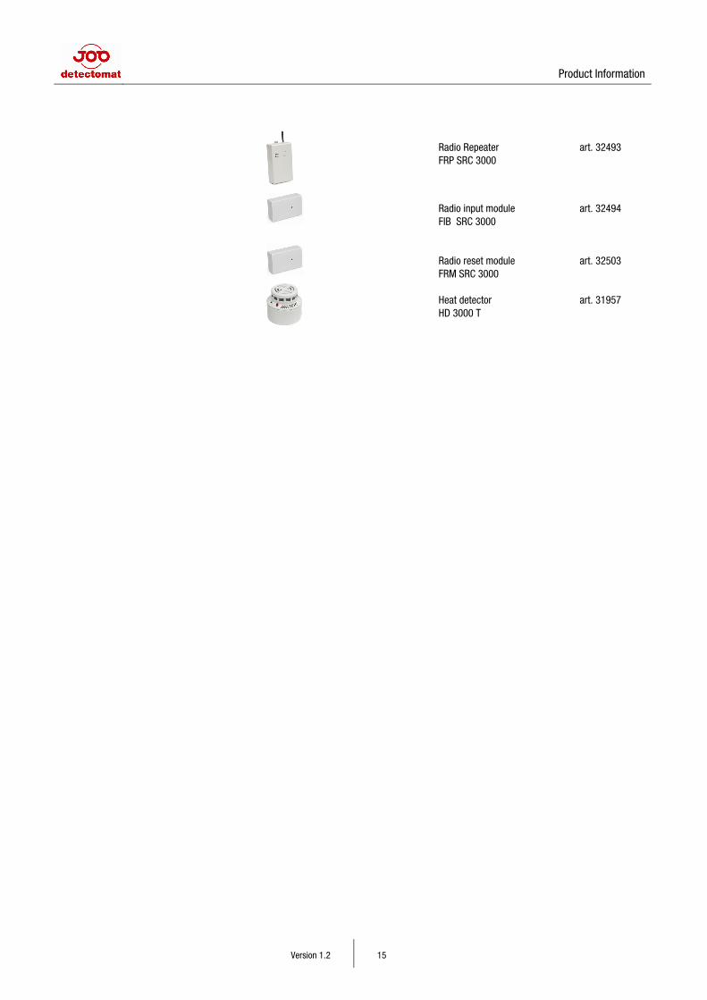
Radio Repeater FRP SRC 3000
art. 32493
Radio input module FIB SRC 3000
art. 32494
Radio reset module FRM SRC 3000
art. 32503
Heat detector HD 3000 T
art. 31957
Installation
Version 1.2 16
4 Installation
4.1 Installation of the radio fire warning panel SRC 3000
Warning! Risk of electric shock.
The electrical installation (power supply 230 V AC) may only be performed by an
authorized electrician!
Before installation and connection of the SRC 3000 radio fire warning panel, disconnect
230 V power supply and take appropriate measures to prevent unintentional re-
connection.
For connecting the radio fire warning panel SRC 3000 to a power supply, please use VDE-
approved connecting terminals. The isolation device and the additional short-circuit protection
must be according to EN 60950 (VDE 0805) or compliant with equivalent local standards for alarm
panel installations in buildings.
Note!
Do not install the SRC 3000 radio fire warning panel in rooms which are too small and
cramped. Otherwise there is the risk of faults caused by radio echo.
1 Open the battery compartment on the left side of the unit. Push the battery compartment
cover in the direction of the arrow.
2 Take out the battery holder and insert the batteries to their corresponding positions.
Observing correct polarity.
3 Connect the battery holder to the battery clip.
4 Put the battery holder with the batteries back into the battery compartment.
5 Close the battery compartment cover.
6 Connect the mains cable from the SRC 3000 panel to the 230 V power supply (N-wire blue,
L1-wire black) to the corresponding connection terminals.
7 Mount the SRC 3000 panel at its intended position. Please use the supplied screws and raw
plugs for mounting the unit. First fix the lower and then the upper screw.
8 Now, switch on 230 V power supply. The SRC 3000 panel will perform a self-test. After that,
the green "Power" LED should be on. The SRC 3000 radio fire warning panel is ready for
operation.
Note!
After inserting the batteries, you will have to wait for at least 10 seconds before starting
the login or commissioning procedure.
Installation
Version 1.2 17
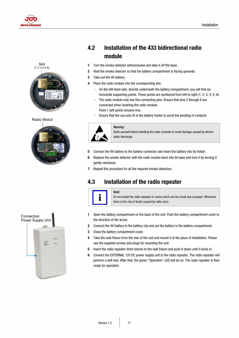
4.2 Installation of the 433 bidirectional radio module
1 Turn the smoke detector anticlockwise and take it off the base.
2 Hold the smoke detector so that the battery compartment is facing upwards.
3 Take out the 9V battery.
4 Place the radio module into the corresponding slot.
− On the left hand side, directly underneath the battery compartment, you will find six
horizontal supporting points. These points are numbered from left to right (1; 2; 3; 4; 5; 6).
− The radio module only has five connecting pins. Ensure that pins 2 through 6 are
connected when inserting the radio module.
Point 1 (left point) remains free.
− Ensure that the cut-outs fit in the battery holder to avoid the bending of contacts.
Warning!
Earth yourself before handling the radio modules to avoid damage caused by electro
static discharge.
5 Connect the 9V battery to the battery connector and insert the battery into its holder.
6 Replace the smoke detector with the radio module back into its base and lock it by turning it
gently clockwise.
7 Repeat this procedure for all the required smoke detectors.
4.3 Installation of the radio repeater
Note!
Do not install the radio repeater in rooms which are too small and cramped. Otherwise
there is the risk of faults caused by radio echo.
1 Open the battery compartment on the back of the unit. Push the battery compartment cover in
the direction of the arrow.
2 Connect the 9V battery to the battery clip and put the battery in the battery compartment.
3 Close the battery compartment cover.
4 Take the wall fixture from the rear of the unit and mount it at the place of installation. Please
use the supplied screws and plugs for mounting the unit.
5 Insert the radio repeater (from below) to the wall fixture and push it down until it locks in.
6 Connect the EXTERNAL 12V DC power supply unit to the radio repeater. The radio repeater will
perform a self-test. After that, the green "Operation" LED will be on. The radio repeater is then
ready for operation.
Logging on radio devices
Version 1.2 18
5 Logging on radio devices
To ensure trouble-free operation of the SRC 3000 radio fire warning panel and the corresponding
radio devices fitted with a radio module, logging on the radio devices should be performed by two
technicians who communicate via mobile phones or radio equipment, etc. One technician will
program the SRC 3000 panel; the other technician will program the radio devices at their place of
installation.
Up to 100 radio devices can be logged onto each SRC 3000 panel in six different zones (Zone 1 to
Zone 6).
Note!
The SRC 3000 panel and the radio repeater should be at their respective places of
installation while being programmed. This way, it is possible to assess the quality of the
radio signal strength indicated on the SRC 3000 panel.
Ensure that all doors within the radio range are closed during the programming
procedure. Otherwise, fault messages may occur during the radio integrity cycle
request from the SRC 3000 panel.
Select the individual zones by pressing the corresponding programming button [P1] to [P6] briefly
(press and release).
5.1 Control authorization via PIN code Configuration and use of the SRC 3000 radio fire warning panel as well as resetting and deletion of
radio devices are PIN code protected. By assigning a PIN code, it is ensured that only authorized
personnel can edit or delete the programming and settings of the SRC 3000 radio fire warning
panel. In the case of certain functions, the PIN code will be requested several times.
Once entered, the PIN will be active for 10 minutes. During this time, you can change the settings
of the SRC 3000 radio fire warning panel without having to re-enter the PIN code.
The default PIN code is 1111. It is recommended that the default settings should be changed.
Logging on radio devices
Version 1.2 19
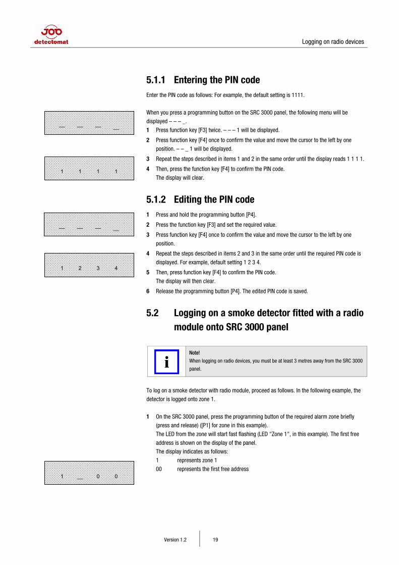
5.1.1 Entering the PIN code Enter the PIN code as follows: For example, the default setting is 1111.
When you press a programming button on the SRC 3000 panel, the following menu will be
displayed – – – _.
1 Press function key [F3] twice. – – – 1 will be displayed.
2 Press function key [F4] once to confirm the value and move the cursor to the left by one
position. – – _ 1 will be displayed.
3 Repeat the steps described in items 1 and 2 in the same order until the display reads 1 1 1 1.
4 Then, press the function key [F4] to confirm the PIN code.
The display will clear.
5.1.2 Editing the PIN code 1 Press and hold the programming button [P4].
2 Press the function key [F3] and set the required value.
3 Press function key [F4] once to confirm the value and move the cursor to the left by one
position.
4 Repeat the steps described in items 2 and 3 in the same order until the required PIN code is
displayed. For example, default setting 1 2 3 4.
5 Then, press function key [F4] to confirm the PIN code.
The display will then clear.
6 Release the programming button [P4]. The edited PIN code is saved.
5.2 Logging on a smoke detector fitted with a radio module onto SRC 3000 panel
Note!
When logging on radio devices, you must be at least 3 metres away from the SRC 3000
panel.
To log on a smoke detector with radio module, proceed as follows. In the following example, the
detector is logged onto zone 1.
1 On the SRC 3000 panel, press the programming button of the required alarm zone briefly
(press and release) ([P1] for zone in this example).
The LED from the zone will start fast flashing (LED "Zone 1", in this example). The first free
address is shown on the display of the panel.
The display indicates as follows:
1 represents zone 1
00 represents the first free address
–– –– –– __
1 2 3 4
–– –– –– __
1 1 1 1
1 __ 0 0
Logging on radio devices
Version 1.2 20
Note!
Address 00 = 1st logged on radio device
Address 01 = 2nd logged on radio device
Addresses from 00 to 99 are available.
Independent from the selected zone, the next free address will be assigned when
logging on radio devices to the SRC 3000 panel. This is done irrespective of the type of
radio device (radio smoke detector, radio repeater, etc.).
The following logging on steps should be carried out in sequence.
2 Press and release the programming button on the radio module of the smoke detector to be
logged on. The LED of the radio module will start fast flashing.
3 Now, press the test button on the front of the smoke detector for approx. 5 seconds. If the
signal of the radio module is recognized by the SRC 3000 panel, the LED on the radio module
will stay on. The LED will then turned off again after about1 minute.
4 Follow the logging on procedure for the radio fire warning SRC 3000 panel.
If the programming is successful, the LED "Zone 1" will stay on until the programme button is
pressed again or after 20 minutes
The RF field strength of the received signal will be displayed.
Scale: 000 to 010
5 Note the displayed value from the detector, write this down and store this information near the
SRC 3000 radio fire warning panel.
Example
Address Zone RF field strength Place ID
00 1 007 corridor, basement
01 1 005 Office left, ground floor
Note!
For values ≤ 004, please use a radio repeater to amplify the signal.
After approx. 20 minutes, the LED "Zone 1" and the display will go out on the SRC 3000 panel.
The display and the LED "Zone 1" can also be turned off by pressing a programming once button
again.
The smoke detector with radio module is now logged on. To log on more smoke detectors fitted
with radio modules, proceed as described in section "5.2 Logging on a smoke detector fitted with
a radio module onto SRC 3000 panel" on Page 19.
Double addressing and re-checking the radio signal strength If you try to log on a radio device which has already been logged on this will be indicated on the
panel with the LED “Device”, also the display will show the current zone and device address.
Additionally by pressing the button [F3] the current signal strength from that device will be viewed.
By carrying out the above, it is possible to re-check the signal strength of a radio device.
Logging on radio devices
Version 1.2 21
5.2.1 Minimising errors during the login process In the case of errors during the logging on of smoke detectors, proceed as follows:
• Delete the relevant smoke detector with radio module from the SRC 3000 panel as described
in section "6.1 Deleting radio device directly from the SRC 3000 panel" on page 25.
• Then, reset the smoke detector with radio module according to section "6.4.1 Performing a
reset on smoke detector fitted with a radio module" on Page 27.
• If necessary, log on the smoke detector again. For more information, refer to section "5.2
Logging on a smoke detector fitted with a radio module onto SRC 3000 panel" on Page 19.
5.2.2 Deactivation of acoustic signalling on a smoke detector fitted with a radio module
If you want to deactivate the acoustic signalling of received alarms on a smoke detector fitted with
a radio module, proceed as follows:
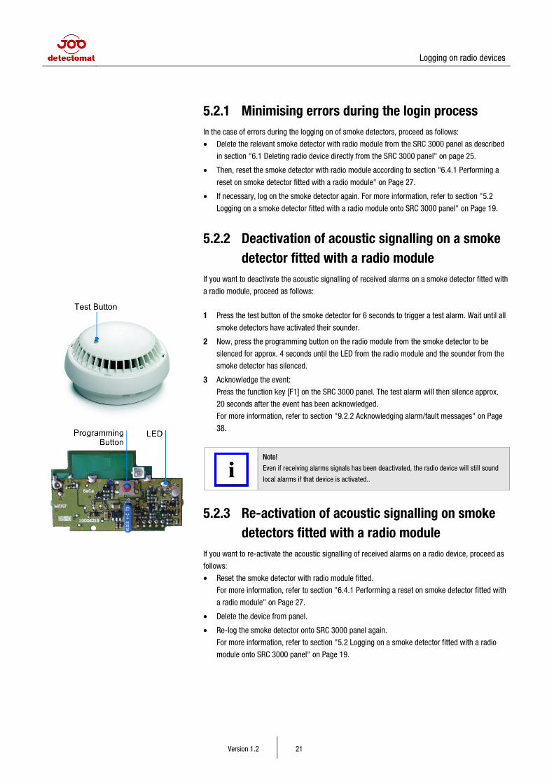
1 Press the test button of the smoke detector for 6 seconds to trigger a test alarm. Wait until all
smoke detectors have activated their sounder.
2 Now, press the programming button on the radio module from the smoke detector to be
silenced for approx. 4 seconds until the LED from the radio module and the sounder from the
smoke detector has silenced.
3 Acknowledge the event:
Press the function key [F1] on the SRC 3000 panel. The test alarm will then silence approx.
20 seconds after the event has been acknowledged.
For more information, refer to section "9.2.2 Acknowledging alarm/fault messages" on Page
38.
Note!
Even if receiving alarms signals has been deactivated, the radio device will still sound
local alarms if that device is activated..
5.2.3 Re-activation of acoustic signalling on smoke detectors fitted with a radio module
If you want to re-activate the acoustic signalling of received alarms on a radio device, proceed as
follows:
• Reset the smoke detector with radio module fitted.
For more information, refer to section "6.4.1 Performing a reset on smoke detector fitted with
a radio module" on Page 27.
• Delete the device from panel.
• Re-log the smoke detector onto SRC 3000 panel again.
For more information, refer to section "5.2 Logging on a smoke detector fitted with a radio
module onto SRC 3000 panel" on Page 19.
Logging on radio devices
Version 1.2 22
5.3 Procedure if radio repeater is used
Note!
If the radio strength is ≤ 004, please use a radio repeater to amplify the signal.
It is important to note that the repeater needs to be logged onto the panel first (Zone 6).
Any device which needs to be logged onto the radio repeater must first of all be logged
onto the SRC 3000 panel. Once the devices have been logged on , only then can you
log them onto the radio repeater.
Do not install the radio repeater in rooms which are too small and cramped. Otherwise
there is the risk of faults occurring due to radio echo.
All radio modules apart from the radio reset module can be logged onto the radio
repeater. The radio reset module needs to be logged directly onto the SRC 3000 panel.
If radio repeaters are used, you must proceed as follows:
• Log the radio repeater onto the SRC 3000 panel (zone 6).
• Check signal between radio repeater and the SRC 3000 panel and reposition it, if necessary.
For more information, refer to section "8.1.2 Testing the communication signal to the radio
repeater" on Page 35.
• Log on any relevant radio devices fitted with radio modules onto SRC 3000 panel.
For more information, refer to section "5.2 Logging on a smoke detector fitted with a radio
module onto SRC 3000 panel" on Page 19.
• Log the relevant radio devices onto radio repeater.
5.3.1 Logging on the repeater to the SRC 3000 panel Now, log the radio repeater onto SRC 3000 panel.
Note!
Radio repeaters can only be logged onto Zone 6 of the SRC 3000 panel.
The radio repeater and SRC 3000 panel should be at their respective places of
installation while being programmed. This way, it is possible to assess the quality of the
radio link based on the signal strengths indicated on the SRC 3000 panel.
When requested, enter the PIN code. For more information, refer to section "5.1.1 Entering the PIN
code" on Page 19.
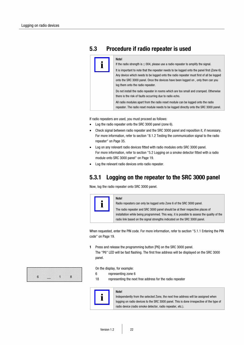
1 Press and release the programming button [P6] on the SRC 3000 panel.
The "P6" LED will be fast flashing. The first free address will be displayed on the SRC 3000
panel.
On the display, for example:
6 representing zone 6
18 representing the next free address for the radio repeater
Note!
Independently from the selected Zone, the next free address will be assigned when
logging on radio devices to the SRC 3000 panel. This is done irrespective of the type of
radio device (radio smoke detector, radio repeater, etc.).
6 __ 1 8
Logging on radio devices
Version 1.2 23
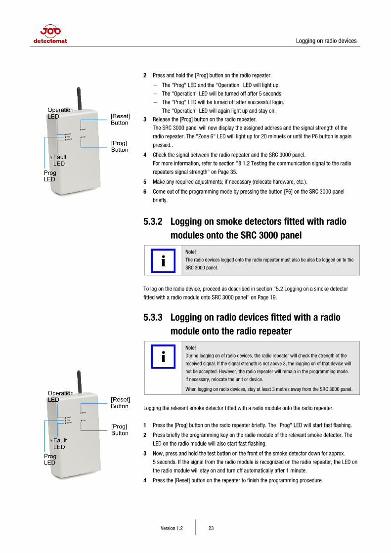
2 Press and hold the [Prog] button on the radio repeater.
− The "Prog" LED and the "Operation" LED will light up.
− The "Operation" LED will be turned off after 5 seconds.
− The "Prog" LED will be turned off after successful login.
− The "Operation" LED will again light up and stay on.
3 Release the [Prog] button on the radio repeater.
The SRC 3000 panel will now display the assigned address and the signal strength of the
radio repeater. The "Zone 6" LED will light up for 20 minuets or until the P6 button is again
pressed..
4 Check the signal between the radio repeater and the SRC 3000 panel.
For more information, refer to section "8.1.2 Testing the communication signal to the radio
repeaters signal strength" on Page 35.
5 Make any required adjustments; if necessary (relocate hardware, etc.).
6 Come out of the programming mode by pressing the button [P6] on the SRC 3000 panel
briefly.
5.3.2 Logging on smoke detectors fitted with radio modules onto the SRC 3000 panel
Note!
The radio devices logged onto the radio repeater must also be also be logged on to the
SRC 3000 panel.
To log on the radio device, proceed as described in section "5.2 Logging on a smoke detector
fitted with a radio module onto SRC 3000 panel" on Page 19.
5.3.3 Logging on radio devices fitted with a radio module onto the radio repeater
Note!
During logging on of radio devices, the radio repeater will check the strength of the
received signal. If the signal strength is not above 3, the logging on of that device will
not be accepted. However, the radio repeater will remain in the programming mode.
If necessary, relocate the unit or device.
When logging on radio devices, stay at least 3 metres away from the SRC 3000 panel.
Logging the relevant smoke detector fitted with a radio module onto the radio repeater.
1 Press the [Prog] button on the radio repeater briefly. The "Prog" LED will start fast flashing.
2 Press briefly the programming key on the radio module of the relevant smoke detector. The
LED on the radio module will also start fast flashing.
3 Now, press and hold the test button on the front of the smoke detector down for approx.
5 seconds. If the signal from the radio module is recognized on the radio repeater, the LED on
the radio module will stay on and turn off automatically after 1 minute.
4 Press the [Reset] button on the repeater to finish the programming procedure.
Logging on radio devices
Version 1.2 24
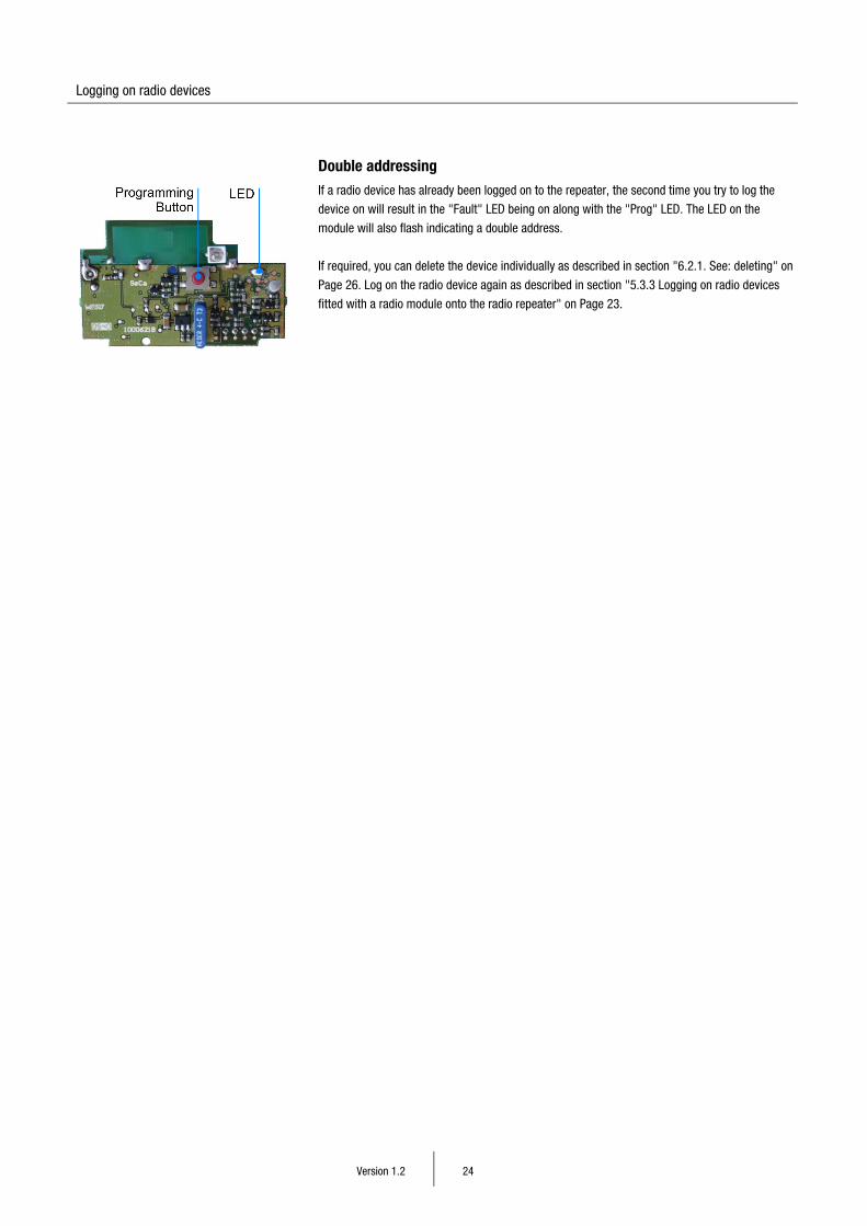
Double addressing If a radio device has already been logged on to the repeater, the second time you try to log the
device on will result in the "Fault" LED being on along with the "Prog" LED. The LED on the
module will also flash indicating a double address.
If required, you can delete the device individually as described in section "6.2.1. See: deleting" on
Page 26. Log on the radio device again as described in section "5.3.3 Logging on radio devices
fitted with a radio module onto the radio repeater" on Page 23.
Deleting radio devices
Version 1.2 25
6 Deleting radio devices
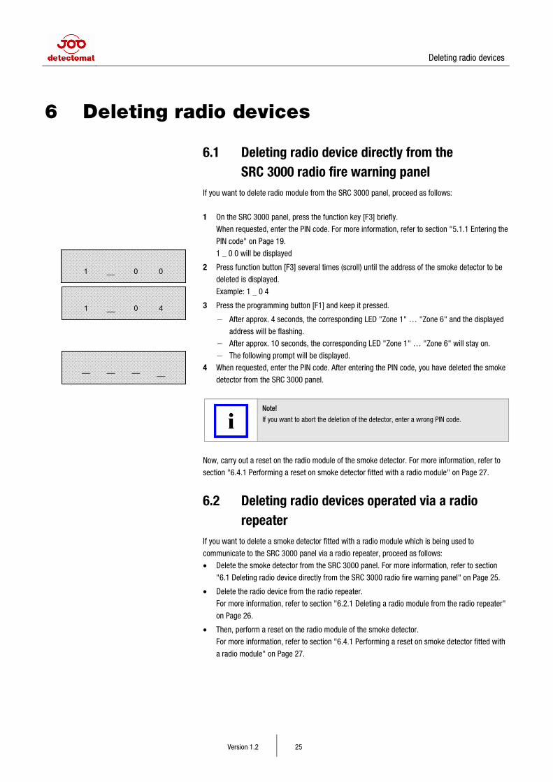
6.1 Deleting radio device directly from the SRC 3000 radio fire warning panel
If you want to delete radio module from the SRC 3000 panel, proceed as follows:
1 On the SRC 3000 panel, press the function key [F3] briefly.
When requested, enter the PIN code. For more information, refer to section "5.1.1 Entering the
PIN code" on Page 19.
1 _ 0 0 will be displayed
2 Press function button [F3] several times (scroll) until the address of the smoke detector to be
deleted is displayed.
Example: 1 _ 0 4
3 Press the programming button [F1] and keep it pressed.
− After approx. 4 seconds, the corresponding LED "Zone 1" … "Zone 6" and the displayed
address will be flashing.
− After approx. 10 seconds, the corresponding LED "Zone 1" … "Zone 6" will stay on.
− The following prompt will be displayed.
4 When requested, enter the PIN code. After entering the PIN code, you have deleted the smoke
detector from the SRC 3000 panel.
Note!
If you want to abort the deletion of the detector, enter a wrong PIN code.
Now, carry out a reset on the radio module of the smoke detector. For more information, refer to
section "6.4.1 Performing a reset on smoke detector fitted with a radio module" on Page 27.
6.2 Deleting radio devices operated via a radio repeater
If you want to delete a smoke detector fitted with a radio module which is being used to
communicate to the SRC 3000 panel via a radio repeater, proceed as follows:
• Delete the smoke detector from the SRC 3000 panel. For more information, refer to section
"6.1 Deleting radio device directly from the SRC 3000 radio fire warning panel" on Page 25.
• Delete the radio device from the radio repeater.
For more information, refer to section "6.2.1 Deleting a radio module from the radio repeater"
on Page 26.
• Then, perform a reset on the radio module of the smoke detector.
For more information, refer to section "6.4.1 Performing a reset on smoke detector fitted with
a radio module" on Page 27.
1 __ 0 0
1 __ 0 4
–– –– –– __
Deleting radio devices
Version 1.2 26
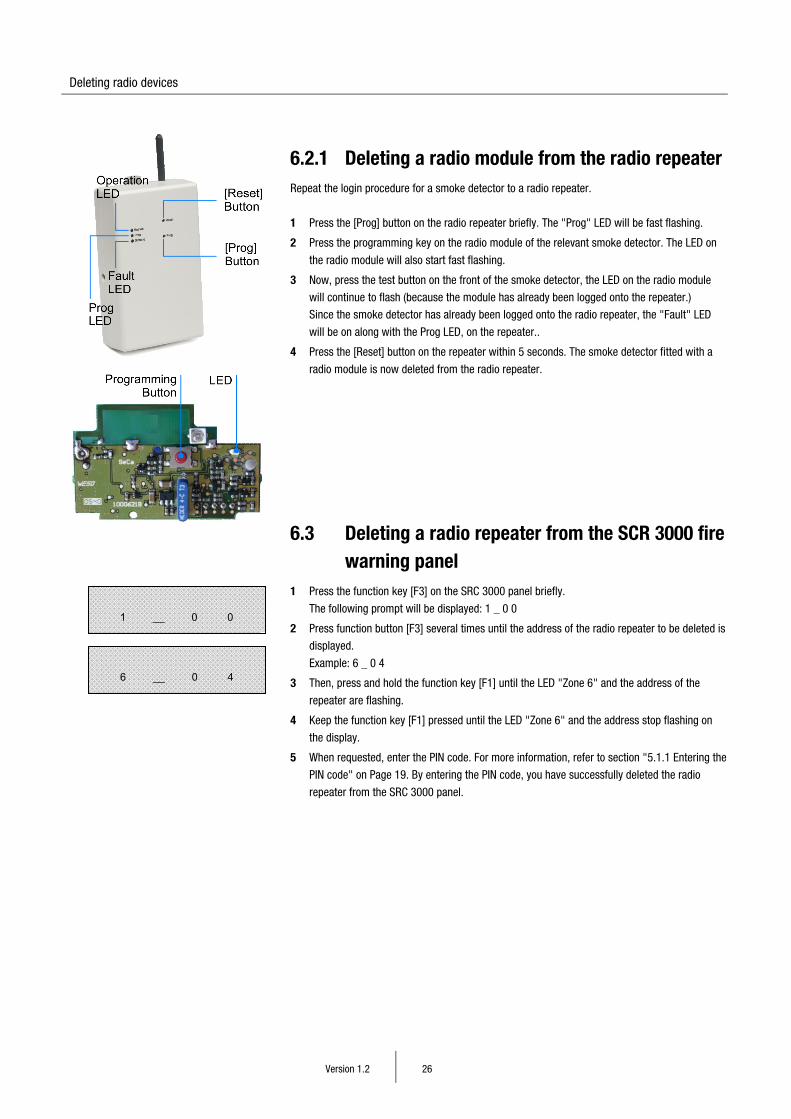
6.2.1 Deleting a radio module from the radio repeater Repeat the login procedure for a smoke detector to a radio repeater.
1 Press the [Prog] button on the radio repeater briefly. The "Prog" LED will be fast flashing.
2 Press the programming key on the radio module of the relevant smoke detector. The LED on
the radio module will also start fast flashing.
3 Now, press the test button on the front of the smoke detector, the LED on the radio module
will continue to flash (because the module has already been logged onto the repeater.)
Since the smoke detector has already been logged onto the radio repeater, the "Fault" LED
will be on along with the Prog LED, on the repeater..
4 Press the [Reset] button on the repeater within 5 seconds. The smoke detector fitted with a
radio module is now deleted from the radio repeater.
6.3 Deleting a radio repeater from the SCR 3000 fire warning panel
1 Press the function key [F3] on the SRC 3000 panel briefly.
The following prompt will be displayed: 1 _ 0 0
2 Press function button [F3] several times until the address of the radio repeater to be deleted is
displayed.
Example: 6 _ 0 4
3 Then, press and hold the function key [F1] until the LED "Zone 6" and the address of the
repeater are flashing.
4 Keep the function key [F1] pressed until the LED "Zone 6" and the address stop flashing on
the display.
5 When requested, enter the PIN code. For more information, refer to section "5.1.1 Entering the
PIN code" on Page 19. By entering the PIN code, you have successfully deleted the radio
repeater from the SRC 3000 panel.
1 __ 0 0
6 __ 0 4
Deleting radio devices
Version 1.2 27
6.4 Reset
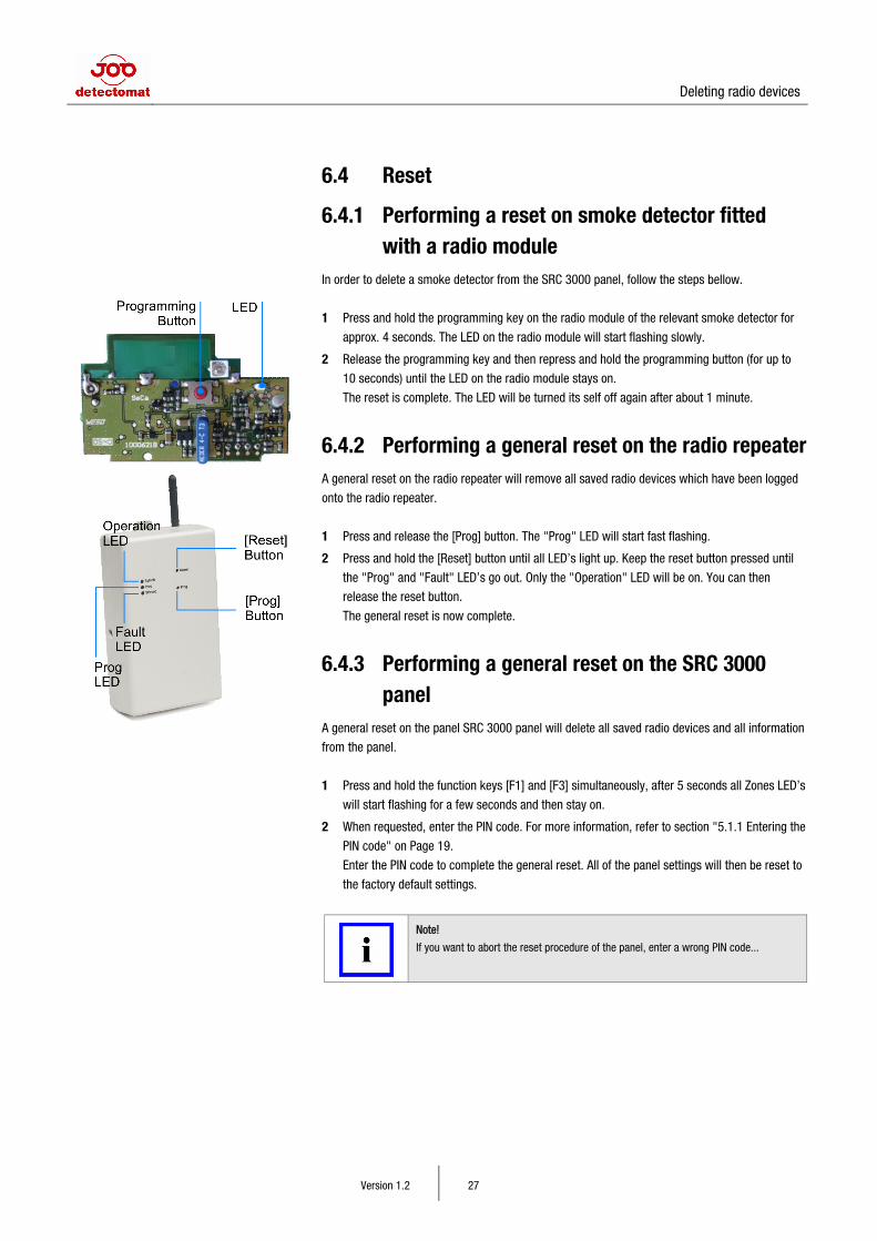
6.4.1 Performing a reset on smoke detector fitted with a radio module
In order to delete a smoke detector from the SRC 3000 panel, follow the steps bellow.
1 Press and hold the programming key on the radio module of the relevant smoke detector for
approx. 4 seconds. The LED on the radio module will start flashing slowly.
2 Release the programming key and then repress and hold the programming button (for up to
10 seconds) until the LED on the radio module stays on.
The reset is complete. The LED will be turned its self off again after about 1 minute.
6.4.2 Performing a general reset on the radio repeater A general reset on the radio repeater will remove all saved radio devices which have been logged
onto the radio repeater.
1 Press and release the [Prog] button. The "Prog" LED will start fast flashing.
2 Press and hold the [Reset] button until all LED’s light up. Keep the reset button pressed until
the "Prog" and "Fault" LED’s go out. Only the "Operation" LED will be on. You can then
release the reset button.
The general reset is now complete.
6.4.3 Performing a general reset on the SRC 3000 panel
A general reset on the panel SRC 3000 panel will delete all saved radio devices and all information
from the panel.
1 Press and hold the function keys [F1] and [F3] simultaneously, after 5 seconds all Zones LED’s
will start flashing for a few seconds and then stay on.
2 When requested, enter the PIN code. For more information, refer to section "5.1.1 Entering the
PIN code" on Page 19.
Enter the PIN code to complete the general reset. All of the panel settings will then be reset to
the factory default settings.
Note!
If you want to abort the reset procedure of the panel, enter a wrong PIN code...
Configuration
Version 1.2 28
7 Configuration
7.1 Configuration of the SRC 3000 panel
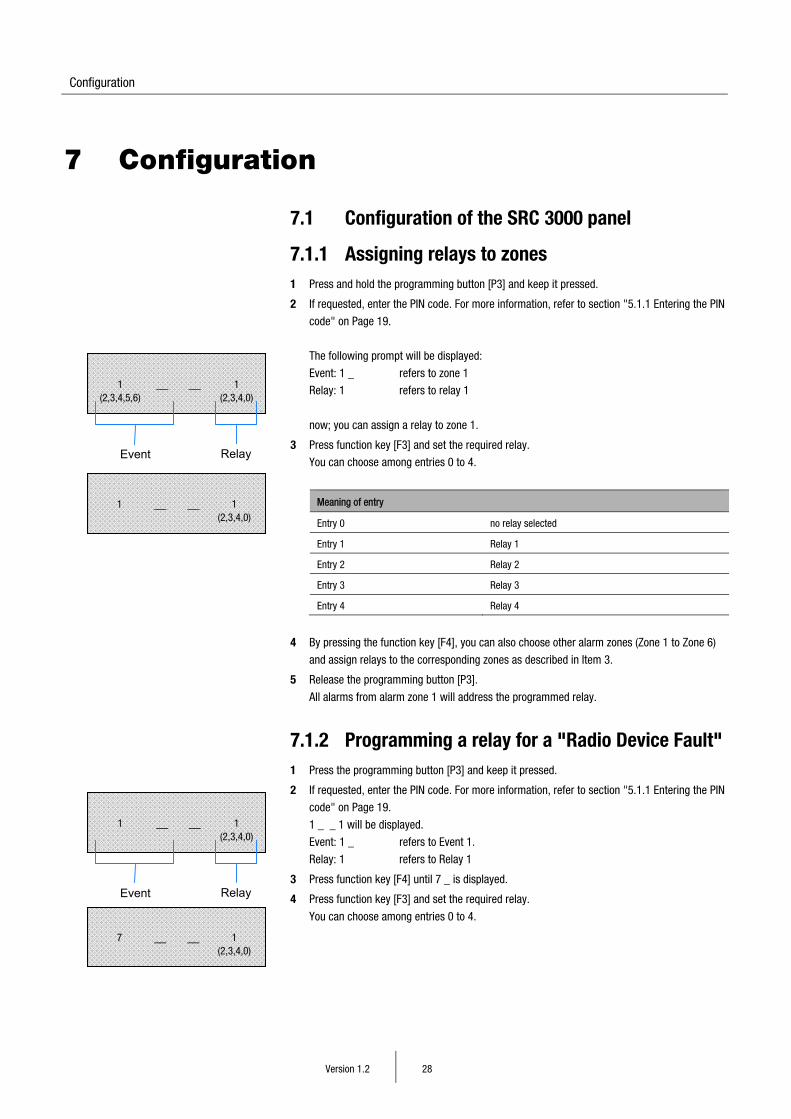
7.1.1 Assigning relays to zones 1 Press and hold the programming button [P3] and keep it pressed.
2 If requested, enter the PIN code. For more information, refer to section "5.1.1 Entering the PIN
code" on Page 19.
The following prompt will be displayed:
Event: 1 _ refers to zone 1
Relay: 1 refers to relay 1
now; you can assign a relay to zone 1.
3 Press function key [F3] and set the required relay.
You can choose among entries 0 to 4.
Meaning of entry
Entry 0 no relay selected
Entry 1 Relay 1
Entry 2 Relay 2
Entry 3 Relay 3
Entry 4 Relay 4
4 By pressing the function key [F4], you can also choose other alarm zones (Zone 1 to Zone 6)
and assign relays to the corresponding zones as described in Item 3.
5 Release the programming button [P3].
All alarms from alarm zone 1 will address the programmed relay.
7.1.2 Programming a relay for a "Radio Device Fault" 1 Press the programming button [P3] and keep it pressed.
2 If requested, enter the PIN code. For more information, refer to section "5.1.1 Entering the PIN
code" on Page 19.
1 _ _ 1 will be displayed.
Event: 1 _ refers to Event 1.
Relay: 1 refers to Relay 1
3 Press function key [F4] until 7 _ is displayed.
4 Press function key [F3] and set the required relay.
You can choose among entries 0 to 4.
7 __ __ 1 (2,3,4,0)
1 (2,3,4,5,6)
__ __ 1 (2,3,4,0)
Event Relay
1 __ __ 1 (2,3,4,0)
Event Relay
1 __ __ 1 (2,3,4,0)
Configuration
Version 1.2 29
Meaning of entry
Entry 0 no relay selected
Entry 1 Relay 1
Entry 2 Relay 2
Entry 3 Relay 3
Entry 4 Relay 4
5 Release the programming button [P3].
All radio device fault messages are now assigned to one relay.
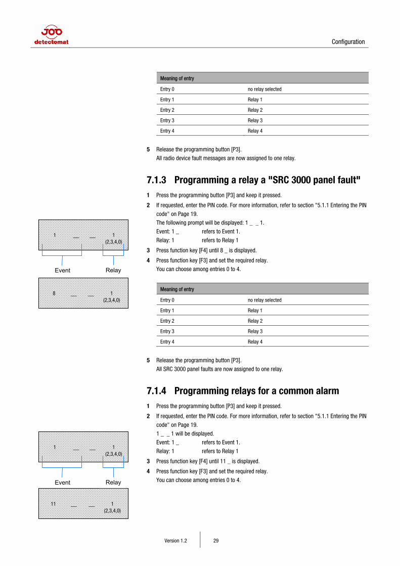
7.1.3 Programming a relay a "SRC 3000 panel fault" 1 Press the programming button [P3] and keep it pressed.
2 If requested, enter the PIN code. For more information, refer to section "5.1.1 Entering the PIN
code" on Page 19.
The following prompt will be displayed: 1 _ _ 1.
Event: 1 _ refers to Event 1.
Relay: 1 refers to Relay 1
3 Press function key [F4] until 8 _ is displayed.
4 Press function key [F3] and set the required relay.
You can choose among entries 0 to 4.
Meaning of entry
Entry 0 no relay selected
Entry 1 Relay 1
Entry 2 Relay 2
Entry 3 Relay 3
Entry 4 Relay 4
5 Release the programming button [P3].
All SRC 3000 panel faults are now assigned to one relay.
7.1.4 Programming relays for a common alarm 1 Press the programming button [P3] and keep it pressed.
2 If requested, enter the PIN code. For more information, refer to section "5.1.1 Entering the PIN
code" on Page 19.
1 _ _ 1 will be displayed.
Event: 1 _ refers to Event 1.
Relay: 1 refers to Relay 1
3 Press function key [F4] until 11 _ is displayed.
4 Press function key [F3] and set the required relay.
You can choose among entries 0 to 4.
8 __ __ 1 (2,3,4,0)
11 __ __ 1 (2,3,4,0)
1 __ __ 1 (2,3,4,0)
Event Relay
1 __ __ 1 (2,3,4,0)
Event Relay
Configuration
Version 1.2 30
Meaning of entry
Entry 0 no relay selected
Entry 1 Relay 1
Entry 2 Relay 2
Entry 3 Relay 3
Entry 4 Relay 4
5 Release the programming button [P3].
Common alarm is now assigned to a relay.
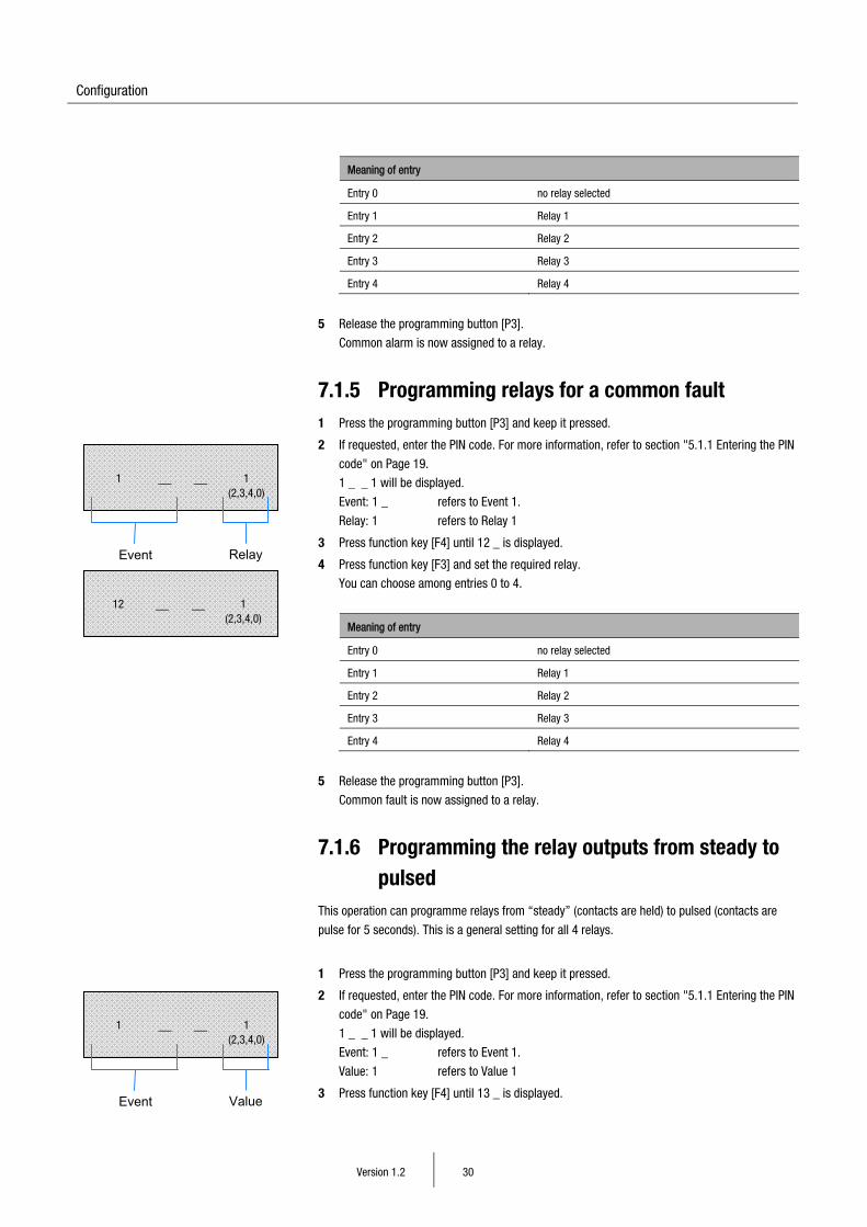
7.1.5 Programming relays for a common fault 1 Press the programming button [P3] and keep it pressed.
2 If requested, enter the PIN code. For more information, refer to section "5.1.1 Entering the PIN
code" on Page 19.
1 _ _ 1 will be displayed.
Event: 1 _ refers to Event 1.
Relay: 1 refers to Relay 1
3 Press function key [F4] until 12 _ is displayed.
4 Press function key [F3] and set the required relay.
You can choose among entries 0 to 4.
Meaning of entry
Entry 0 no relay selected
Entry 1 Relay 1
Entry 2 Relay 2
Entry 3 Relay 3
Entry 4 Relay 4
5 Release the programming button [P3].
Common fault is now assigned to a relay.
7.1.6 Programming the relay outputs from steady to pulsed
This operation can programme relays from “steady” (contacts are held) to pulsed (contacts are
pulse for 5 seconds). This is a general setting for all 4 relays.
1 Press the programming button [P3] and keep it pressed.
2 If requested, enter the PIN code. For more information, refer to section "5.1.1 Entering the PIN
code" on Page 19.
1 _ _ 1 will be displayed.
Event: 1 _ refers to Event 1.
Value: 1 refers to Value 1
3 Press function key [F4] until 13 _ is displayed.
12 __ __ 1 (2,3,4,0)
1 __ __ 1 (2,3,4,0)
Event Relay
1 __ __ 1 (2,3,4,0)
Event Value
Configuration
Version 1.2 31
4 Press function key [F3] and set the required value.
You can select either a 0 or a 1.
Meaning of entry
0 = Relays steady
1 = Relays pulsed
5 Release the programming button [P3].
Steady or pulsed relays have now been set.
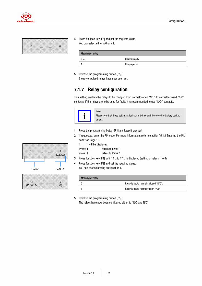
7.1.7 Relay configuration This setting enables the relays to be changed from normally open “N/O” to normally closed “N/C”
contacts. If the relays are to be used for faults it is recommended to use “N/O” contacts.
Note!
Please note that these settings affect current draw and therefore the battery backup
times...
1 Press the programming button [P3] and keep it pressed.
2 If requested, enter the PIN code. For more information, refer to section "5.1.1 Entering the PIN
code" on Page 19.
1 _ _ 1 will be displayed.
Event: 1 _ refers to Event 1
Value: 1 refers to Value 1
3 Press function key [F4] until 14 _ to 17 _ is displayed (setting of relays 1 to 4).
4 Press function key [F3] and set the required value.
You can choose among entries 0 or 1.
Meaning of entry
0 Relay is set to normally closed “N/C”.
1 Relay is set to normally open “N/O”
5 Release the programming button [P3].
The relays have now been configured either to “N/O and N/C”.
13 __ __ 0 (1)
14 (15,16,17)
__ __ 0 (1)
1 __ __ 1 (2,3,4,0)
Event Value
Configuration
Version 1.2 32
7.1.8 Programming overview table for sections 7.1.1 to 7.1.7
Programming button Function Notes
[P3] Relay assignment Four relays can be configured to react to different events.
Default setting
No. Event Display
1 Alarm zone 1 (section 7.1.1) 1 _ _ 1
2 Alarm zone 2 (section 7.1.1) 2 _ _ 2
3 Alarm zone 3 (section 7.1.1) 3 _ _ 2
4 Alarm zone 4 (section 7.1.1) 4 _ _ 3
5 Alarm zone 5 (section 7.1.1) 5 _ _ 3
6 Alarm zone 6 (section 7.1.1) 6 _ _ 4
7 Radio device fault (section 7.1.2) 7 _ _ 0
8 SRC 3000 panel fault (section 7.1.3) 8 _ _ 0
11 Common alarm (section 7.1.4) 1 1 _ 0
12 Common fault (section 7.1.5) 1 2 _ 0
13 Operation mode: 0-steady,1-pulsed (sections 7.1.6) 1 3 _ 0
14 Relay 1 Normally open “N/0” 0 / Normally closed “N/C” 1 (section 7.1.7)
1 4 _ 0
15 Relay 2 Normally open “N/O” 0 / Normally closed “N/C” 1 (section 7.1.7)
1 5 _ 0
16 Relay 3 Normally open “N/O” 0 / Normally closed “N/C” 1 (section 7.1.7)
1 6 _ 0
17 Relay 4 Normally open “N/O” 0 / Normally closed “N/C” 1 (section 7.1.7)
1 7 _ 0
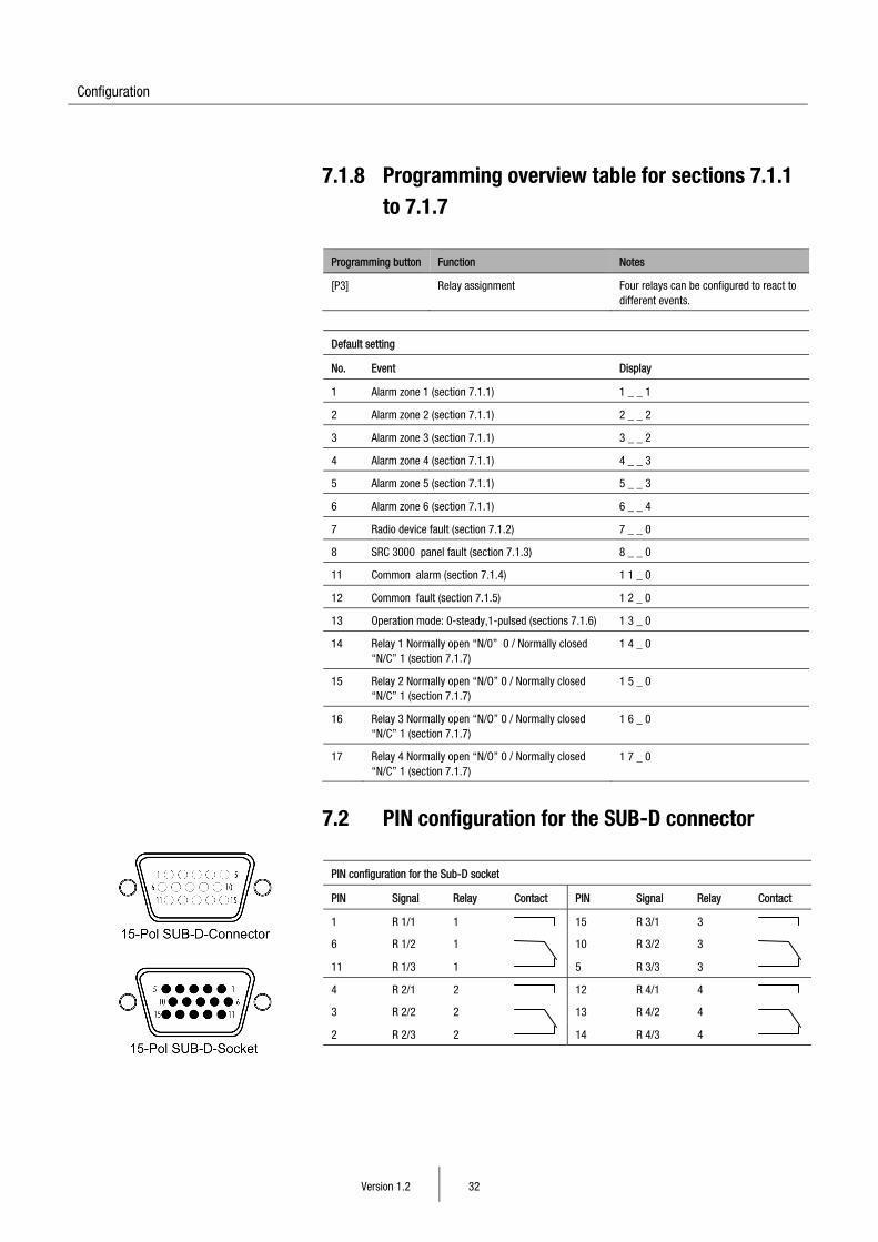
7.2 PIN configuration for the SUB-D connector
PIN configuration for the Sub-D socket
PIN Signal Relay Contact PIN Signal Relay Contact
1 R 1/1 1 15 R 3/1 3
6 R 1/2 1
10 R 3/2 3
11 R 1/3 1 5 R 3/3 3
4 R 2/1 2 12 R 4/1 4
3 R 2/2 2
13 R 4/2 4
2 R 2/3 2 14 R 4/3 4
Configuration
Version 1.2 33
7.3 Special configurations
7.3.1 Parameter 1 Fault message "Radio" indicates a radio fault with the communication between the panel and a
module. This fault can be set to non latching (resets automatically as soon as the radio
communication is re-established). (Value 1) or latching (value 0 = default setting) meaning the
panel needs to be reset manually via the reset button.
7.3.2 Parameter 2 For all faults received by the SRC 3000 panel, such device, battery, radio, or alarms, a tone
indication will sound (approx. 45 seconds) on the SRC 3000 panel until the event is acknowledged
by pressing the reset button. The default, value 0 (ON) is set. When set to value 1 (OFF) no tone
will be sounded.
7.3.3 Parameter 3 With this setting you have the option to enable/disable the PIN code. Meaning when the value 0
(default) is set, any panel actions require the PIN to be entered. When the value is set to 1, the PIN
is not required.
7.3.4 Parameter 4 Here, you can activate/deactivate the displaying of radio fault messages. All other faults will be
displayed. By default, the value is set to 0 (ON) meaning radio faults will be displayed.
Programming the parameters 1 Press and hold the programming button [P1].
2 If requested, enter the PIN code. For more information, refer to section "5.1.1 Entering the PIN
code" on Page 19.
1 _ _ 1 will be displayed.
Parameter: 1 _
Value: 0
3 Press function key [F4] until the required parameter is displayed.
4 Press function key [F3] and set the required value.
You can switch between 0 and 1.
No. Parameter Set values
1 Automatic resetting of radio fault messages
OFF 0
ON 1
2 Faults / Events reminder sound
ON 0
OFF 1
3 PIN requirement ON 0
OFF 1
4 Displaying of radio fault messages ON 0
OFF 1
5 Release the programming button [P1]. The corresponding parameters are set.
1 (2,3,4)
__ __ 0 (1)
1 __ __ 0 (1)
Parameter Value
Commissioning
Version 1.2 34
8 Commissioning
8.1 Functionality tests Check the configuration of your system using the function test described below.
Firstly, select the radio devices which are the furthest in distance away from the SRC 3000 panel
or any devices which you think could or might incur radio problems.. If any device has no radio
communication with the SRC 3000 panel, or the radio signal is below 4 we would recommend
using a radio repeater. NOTE: Cascading of radio repeaters is not possible.
Note!
Repeat the function tests at least once a year during service and maintenance of the
system.
If the following function tests are carried out after a service/maintenance check, that
the inspection/maintenance mode has been deactivated before leaving site. For more
information, refer to section "10.2.1 Activating/deactivating the service mode" on
Page 39.
8.1.1 Alarm testing 1 Press down the test button on the detector. The alarm will be displayed on the SRC 3000
panel immediately.
Further alarm testing steps:
• Within 20 seconds, the SRC 3000 panel, if it has received the alarm signal, activates the
sounders of all the smoke detectors which are fitted with radio modules and are logged onto
the SRC 3000 panel.
• If the SRC 3000 panel needs to transmit via repeaters, the smoke detectors logged onto the
repeaters will have the following delays:
− One radio repeater fitted means all devices logged on will have
an additional 20 seconds delay
− Two radio repeaters fitted means all devices logged on will have
an additional 40 seconds delay
− Three radio repeaters fitted means all devices logged on will have
an additional 60 seconds delay
Acknowledge the event on the SRC 3000 panel:
1 Press function key [F1].
2 If requested, enter the PIN code. For more information, refer to section "5.1.1 Entering the PIN
code" on Page 19. The alarm test will go out after 20 seconds.
Note!
If the radio communication between the SRC 3000 panel and the radio modules does
respond correctly, the alarm broadcast to the radio devices will be stop automatically
after 20 minutes.
Commissioning
Version 1.2 35
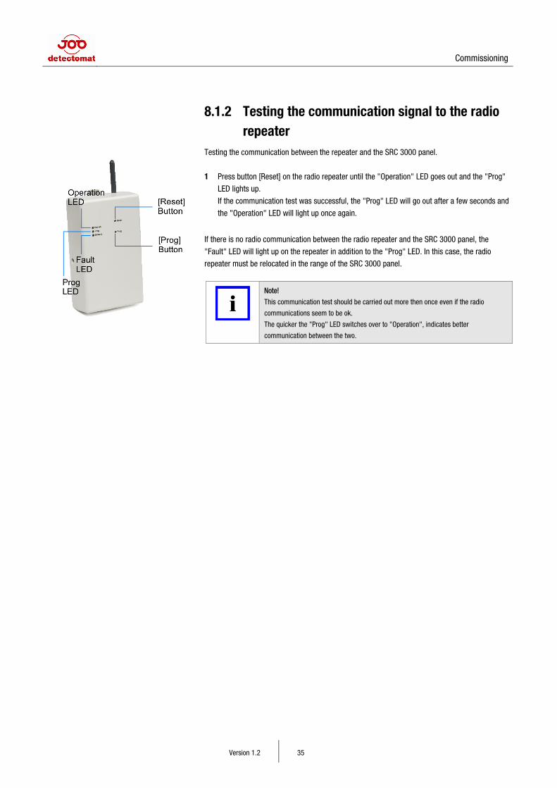
8.1.2 Testing the communication signal to the radio repeater
Testing the communication between the repeater and the SRC 3000 panel.
1 Press button [Reset] on the radio repeater until the "Operation" LED goes out and the "Prog"
LED lights up.
If the communication test was successful, the "Prog" LED will go out after a few seconds and
the "Operation" LED will light up once again.
If there is no radio communication between the radio repeater and the SRC 3000 panel, the
"Fault" LED will light up on the repeater in addition to the "Prog" LED. In this case, the radio
repeater must be relocated in the range of the SRC 3000 panel.
Note!
This communication test should be carried out more then once even if the radio
communications seem to be ok.
The quicker the "Prog" LED switches over to "Operation", indicates better
communication between the two.
Operation
Version 1.2 36
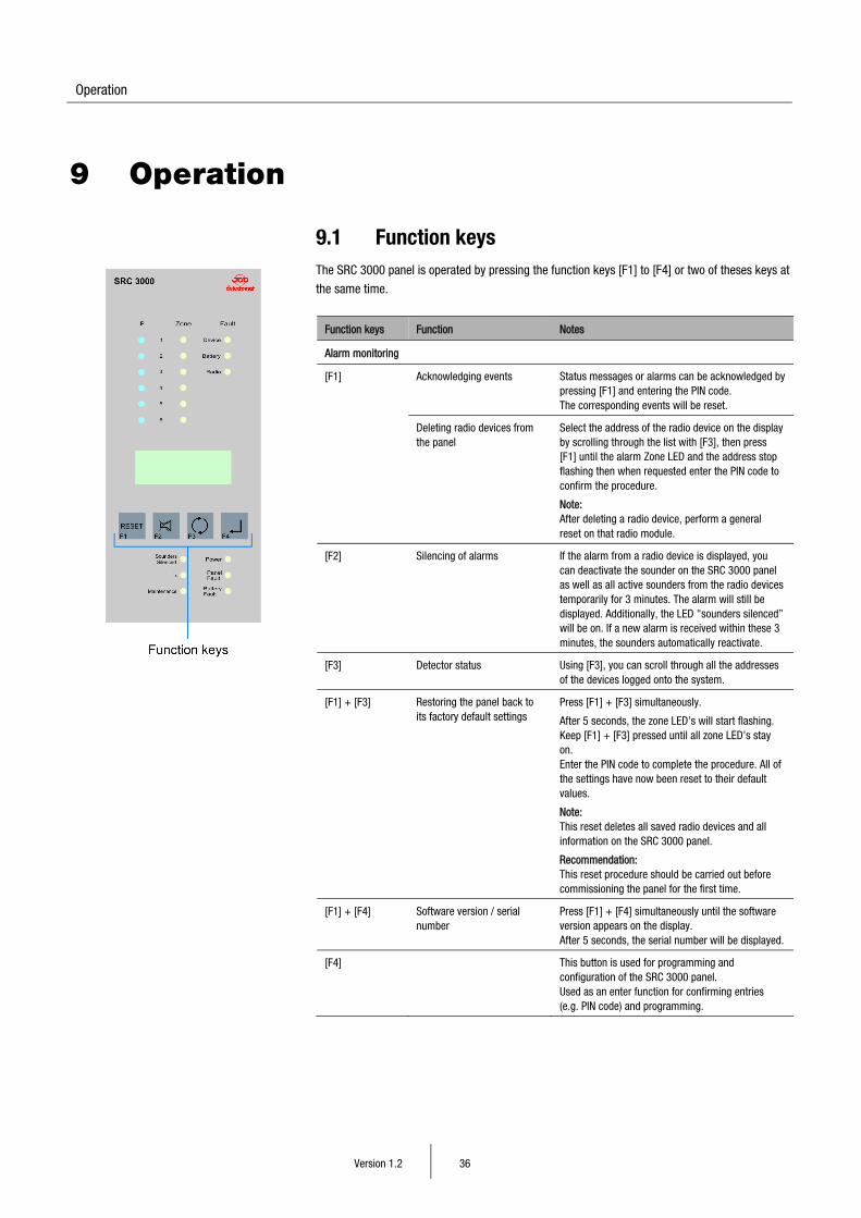
9 Operation
9.1 Function keys The SRC 3000 panel is operated by pressing the function keys [F1] to [F4] or two of theses keys at
the same time.
Function keys Function Notes
Alarm monitoring
[F1] Acknowledging events Status messages or alarms can be acknowledged by pressing [F1] and entering the PIN code. The corresponding events will be reset.
Deleting radio devices from the panel
Select the address of the radio device on the display by scrolling through the list with [F3], then press [F1] until the alarm Zone LED and the address stop flashing then when requested enter the PIN code to confirm the procedure.
Note: After deleting a radio device, perform a general reset on that radio module.
[F2] Silencing of alarms If the alarm from a radio device is displayed, you can deactivate the sounder on the SRC 3000 panel as well as all active sounders from the radio devices temporarily for 3 minutes. The alarm will still be displayed. Additionally, the LED "sounders silenced” will be on. If a new alarm is received within these 3 minutes, the sounders automatically reactivate.
[F3] Detector status Using [F3], you can scroll through all the addresses of the devices logged onto the system.
[F1] + [F3]
Restoring the panel back to its factory default settings
Press [F1] + [F3] simultaneously.
After 5 seconds, the zone LED’s will start flashing. Keep [F1] + [F3] pressed until all zone LED’s stay on. Enter the PIN code to complete the procedure. All of the settings have now been reset to their default values.
Note: This reset deletes all saved radio devices and all information on the SRC 3000 panel.
Recommendation: This reset procedure should be carried out before commissioning the panel for the first time.
[F1] + [F4] Software version / serial number
Press [F1] + [F4] simultaneously until the software version appears on the display. After 5 seconds, the serial number will be displayed.
[F4] This button is used for programming and configuration of the SRC 3000 panel. Used as an enter function for confirming entries (e.g. PIN code) and programming.
Operation
Version 1.2 37
9.2 Alarms and faults
9.2.1 Signalling of alarms and faults
Alarms from radio devices If an alarm is detected by a radio device for more than 5 seconds, the following process is
activated:
• The radio module sends a signal to the SRC 3000 panel.
− The alarm is indicated by one of the 6 zone LED’s, 1 to 6 is displayed along with the
address of the activated device.
• Within 20 seconds, the radio SRC 3000 panel, if it receives the alarm signal, activates, the
sounders, of the detectors which are logged onto the SRC 3000 panel.
• If the SRC 3000 panel needs to transmit via a radio repeater, the communication is delayed as
follows:
− One radio repeater fitted means all devices logged on will have
an additional 20 seconds delay
− Two radio repeaters fitted means all devices logged on will have
an additional 40 seconds delay
− Three radio repeaters fitted means all devices logged on will have
an additional 60 seconds delay
Faults from radio devices On the SRC 3000 panel, faults from the radio devices are displayed in three different categories:
Device The "Device" fault message indicates that the smoke measuring chamber from the detector is or
has been contaminated.
Recommendation: Replace the affected radio device.
Display on the SRC 3000 panel
LED LED colour Display
Device Yellow Zone Address (radio device)
Display on the radio device (e.g. radio smoke detector)
LED LED colour Signal
On the radio smoke detector
Yellow LED flashes (intervals of one per minute)
brief tone (intervals of one per minute)
Note!
"Device" faults on the radio smoke detectors are characterized by alternant flashing of
the LED on the front and the short signal tone (tone, flash, tone, flash, ...).
Battery The "Battery" fault message indicates that the batteries in the radio smoke detector are low.
Recommendation: Replace the batteries.
Operation
Version 1.2 38
Display on the SRC 3000 panel
LED LED colour Display
Battery Yellow Zone (area, zone) Address (radio device)
Display on the radio device (e.g. smoke detector)
LED LED colour Signal
On the radio smoke detector
Yellow LED flashes (intervals of one per minute)
brief tone (intervals of one per minute)
Note!
"Battery" faults on the smoke detector are characterized by the LED flashing and the
tone sounding at the same time.
Radio The "Radio" fault message indicates that in the radio integrity check of six unsuccessful cycles
(time between cycles = 4 hours), has been detected between the SRC 3000 panel and the
displayed radio devices.
Recommendation in the case of an existing system: Check the premises. Were any structural
changes might have been made (new walls, doors or large furniture)?
If necessary, use a radio repeater. In this case, the radio devices must be logged on again.
Recommendation in the case of new systems: Use a radio repeater and/or relocate the radio
device.
Display on the SRC 3000 panel
LED LED colour Display
Radio Yellow Zone (area, zone) Address (radio device)
Note!
If the SRC 3000 panel receives a communication signal again, the "Radio" fault will be
reset automatically. The automatic reset function can however be deactivated. For
more information, refer to section "7.3 Special configuration" on Page 33.
9.2.2 Acknowledging alarm/fault messages 1 Note the displayed address of the radio device.
2 If necessary, press function key [F2] to switch off the panel tone temporarily. After 3 minutes,
or when a new alarm is received, it will be automatically reactivated.
3 Press function key [F1].
4 When requested, enter the PIN code. For more information, refer to section "5.1.1 Entering the
PIN code" on Page 19.
− The alarm/fault on the display of the SRC 3000 radio fire warning panel will go out.
− The SRC 3000 panel is now reset.
− The sounders of the radio devices (only in the case of alarm) will be reset within approx.
20 seconds.
Maintenance
Version 1.2 39
10 Maintenance
10.1 Inspection and maintenance intervals To ensure the system is kept working and well maintained, regular inspections and tests must be
carried out
Type of tests to be carried out
daily
weekly
monthly
yearly
as
required
Checks/maintenance
Function test Test alarm
Test of connection to radio repeater
X
X
X
10.2 Maintenance/Service measures
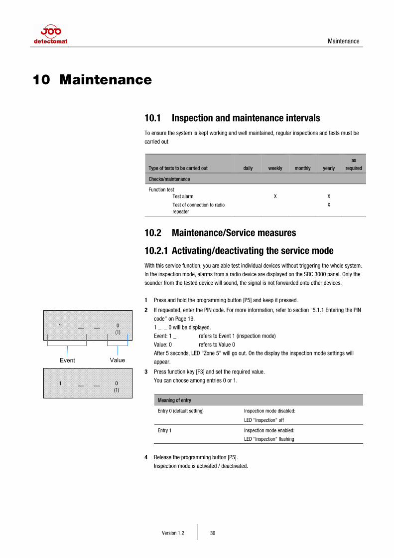
10.2.1 Activating/deactivating the service mode With this service function, you are able test individual devices without triggering the whole system.
In the inspection mode, alarms from a radio device are displayed on the SRC 3000 panel. Only the
sounder from the tested device will sound, the signal is not forwarded onto other devices.
1 Press and hold the programming button [P5] and keep it pressed.
2 If requested, enter the PIN code. For more information, refer to section "5.1.1 Entering the PIN
code" on Page 19.
1 _ _ 0 will be displayed.
Event: 1 _ refers to Event 1 (inspection mode)
Value: 0 refers to Value 0
After 5 seconds, LED "Zone 5" will go out. On the display the inspection mode settings will
appear.
3 Press function key [F3] and set the required value.
You can choose among entries 0 or 1.
Meaning of entry
Entry 0 (default setting) Inspection mode disabled:
LED "Inspection" off
Entry 1 Inspection mode enabled:
LED "Inspection" flashing
4 Release the programming button [P5].
Inspection mode is activated / deactivated.
1 __ __ 0 (1)
1 __ __ 0 (1)
Event Value
Maintenance
Version 1.2 40
Note!
If the inspection mode is not disabled manually, it will be reset back to the default
settings after 8 hours non activity. This time can be changed. For more information,
refer to section "10.2.2 Automatic disablement of the inspection mode" on Page 40.
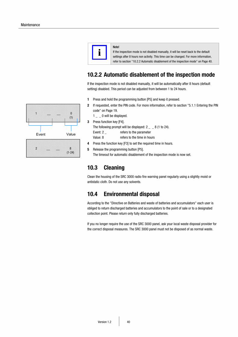
10.2.2 Automatic disablement of the inspection mode If the inspection mode is not disabled manually, it will be automatically after 8 hours (default
setting) disabled. This period can be adjusted from between 1 to 24 hours.
1 Press and hold the programming button [P5] and keep it pressed.
2 If requested, enter the PIN code. For more information, refer to section "5.1.1 Entering the PIN
code" on Page 19.
1 _ _ 0 will be displayed.
3 Press function key [F4].
The following prompt will be displayed: 2 _ _ 8 (1 to 24).
Event: 2 _ refers to the parameter
Value: 8 refers to the time in hours
4 Press the function key [F3] to set the required time in hours.
5 Release the programming button [P5].
The timeout for automatic disablement of the inspection mode is now set.
10.3 Cleaning Clean the housing of the SRC 3000 radio fire warning panel regularly using a slightly moist or
antistatic cloth. Do not use any solvents.
10.4 Environmental disposal According to the "Directive on Batteries and waste of batteries and accumulators" each user is
obliged to return discharged batteries and accumulators to the point of sale or to a designated
collection point. Please return only fully discharged batteries.
If you no longer require the use of the SRC 3000 panel, ask your local waste disposal provider for
the correct disposal measures. The SRC 3000 panel must not be disposed of as normal waste.
2 __ __ 8 (1-24)
1 __ __ 0 (1)
Event Value
Annex 1: List of Abbreviations
Version 1.2 41
Annex 1: List of Abbreviations
Abbreviation Meaning
RoHS Restriction of the use of certain hazardous substances in electrical and electronic equipment
Refers to the EU Directive 2002/95/EC on the restriction of the use of certain hazardous substances in electrical and electronic equipment.