Embed Size (px)
Citation preview
RADIO FREQUENCY INTERFERENCE MITIGATION WITH REAL-TIMEFPGA DIGITAL SIGNAL PROCESSING
Willem Baan, Peter Fridman and Rob Millenaar
ASTRON, Westerbork Radio ObservatoryOude Hoogeveensedijk 4, 7991PD Dwingeloo, The Netherlands (Europe)phone: +31 521 595100, fax: +31 521 597332, email: [email protected]
ABSTRACTThe sensitivity of radio astronomy telescopes is oftenlimited by man-made radio frequency interference dueto a variety of terrestrial activities. An RFI mitigationsubsystem (RFIMS) based on real-time digital signal-processing is proposed for the Westerbork Synthesis Ra-dio Telescope based on a powerful field programmablegate array (FPGA) processor. In this system the radioastronomy signals polluted by RFI are ”cleaned” by theRFIMS before the routine backend correlation process-ing happens. The high temporal and frequency resolu-tion of the RFIMS allows the detection and excision ofRFI.
1. INTRODUCTION
The sensitivity and spectral performance of modern tele-scopes is increasingly affected by the worsening electro-magnetic environment due to population density andincreased spectrum use. At the same time the tech-nology standards at modern radio telescopes have beenraised and low-noise receivers have been significantly im-proved. However, as a result of the presence of radiofrequency interference (RFI) in the data, the potentialof increased sensitivity cannot be reached at all times,especially at frequencies below 1 GHz. The presenceof detrimental RFI in the data translates into effectivedata loss and a lower observing efficiency.
Advances in digital techniques provide vast oppor-tunities for RFI mitigation. A demonstrator RFI mit-igation system has been developed at the WesterborkSyntehsis Radio Telescope (WSRT) that was based ona Signatec PMP-8 digital signal processor (eight DSPTMS320C6201) board and 4-channel 12-bit high-speed(up to 50 Msamples/sec) analog-digital and digital-analog (ADC & DAC) converters. This system was usedto operationally test several RFI mitigation algorithms.
The principal methods used in these tests were:1) time-frequency analysis and outliers excision usingthresholding, 2) RFI suppression using a “RFI estima-tion → subtraction” method, 3) adaptive RFI cancella-tion using a reference channel, and 4) the use of higher-order statistics for analysing the data. These DSP pro-cessing efforts of the real astronomical signals resultedin considerable RFI suppression both for continuum andspectral observations.
As a follow-up to this DSP-based system a second-generation real-time RFI Mitigation System has beenproposed for implementation within the existing WSRTbackend infrastructure. Real-time processing was cho-sen for the RFIMS because very often RFI are unsta-
ble, rapidly changing and very strong. They may be-have like bursts in temporal or frequency domains. TheRFI may produce considerable distortions of averageddata at the correlator output if not “intercepted” be-fore processing in the correlator. RFI at the antennasof such a large and sparse interferometer as the WSRTis sometimes only partly coherent and spatial processingalgorithms are not always effective. Therefore, real-timetime-frequency analysis of the signals at each antenna isa more flexible tool than post correlation processing.
The system is designed so that one of the eight20 MHz wide sub-bands of each of the fourteen tele-scopes gets processed independently between the IFto video conversion (“IVC”) stage and the correlationstage. The full system consists of 28 separate processors,one for each of the polarization channels per telescope(WSRT consists of 14 antennas). State-of-the-art high-performance processors implemented in FPGA’s are be-ing used for this real-time processing stage. It shouldbe noted that this system is essentially a multi-pathprocessing system that could be effectively applied atsingle-dish telescopes as well. This paper reports on thefirst operational results obtained with this RFIMS sys-tem.
2. RFI MITIGATION SYSTEM
The implementation of an RFI mitigation subsys-tem within an existing interferometric signal-processingbackend is a delicate technical problem. In orderto allow implementation, the subsystem should a) beadapted to the input-output specifications and theschematics of the backend, b) be precisely synchronizedwith the correlation processing, and c) keep the usefulradio source signals undistorted and maintain the cor-rect absolute and constant time relations of the multi-channel system. After the last frequency conversionstage in the IVC system, the baseband signals of band-width up to 20 MHz are processed in the RFI mitigationsubsystem before they are applied to the radio interfero-metric correlator. The processed signals should be pre-sented to the correlator as if there were no additionalprocessing stages involved.
Using the experience obtained with the DSP-baseddemonstrator system, a second-generation RFI mitiga-tion subsystem (RFIMS) has been conceived for theWSRT. The design criteria used for the RFIMS systemare based on the following considerations:
1. For processing large quantities of data in a verysimilar manner, a high degree of parallelism, extensivepipelining, dynamic reconfigurability and the realloca-
765
tion of computational units, upgradability and scalabil-ity, are required.
2. High-performance processing cores (DSP, Pen-tium IV) provide a small benefit if the data transferoverhead reduces their processing power to unaccept-able limits. Therefore, the processing power and datatransfer speeds are equally important for system evalu-ations.
3. The signal-processing literature is full of creativesolutions to real-world problems. Often these solutionsare not useful to a designer because they do not map wellto software-programmable DSP architectures. SimilarlyASIC solutions are not an option for reasons of time-scales, economy of scale, and flexibility. On the otherhand, field programmable gate arrays (FPGAs) give im-mediate access to a diverse range of potential solutionsfor high-performance digital processing systems. Thesedevices maintain the flexibility of software-based solu-tions, while providing levels of performance that matchASIC solutions.
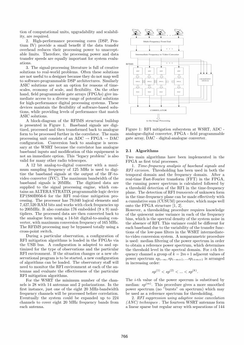
A block-diagram of the RFIMS structural buildupis presented in Figure 1. Baseband signals are digi-tized, processed and then transformed back to analogueform to be processed further in the correlator. The mainprocessing unit consists of an ADC → FPGA → DACconfiguration. Conversion back to analogue is neces-sary at the WSRT because the correlator has analoguebaseband inputs and modification of this equipement isnot an immediate option. This “legacy problem” is alsovalid for many other radio telescopes.
A 12 bit analog-to-digital converter with a maxi-mum sampling frequency of 125 MHz is used to digi-tize the baseband signals at the output of the IF-to-video converter (IVC). The maximum bandwidth of thebaseband signals is 20MHz. The digitized data aresupplied to the signal processing engine, which con-tains an ALTERA STRATIX programmable logic deviceEP1S80B956-6 for the RFI real-time mitigation pro-cessing. The processor has 79,040 logical elements and7,427,520 RAM bits and works with clock frequencies upto 200MHz. It also contains 176 embedded (9 x 9) mul-tipliers. The processed data are then converted back tothe analogue form using a 14-bit digital-to-analog con-verter, with maximum conversion frequency of 165 MHz.The RFIMS processing may be bypassed totally using across-point switch.
During a particular observation, a configuration ofRFI mitigation algorithms is loaded in the FPGAs viathe USB bus. A configuration is adapted to and op-timized for the type of observations and the particularRFI environment. If the situation changes or a new ob-servational program is to be started, a new configurationof algorithms can be loaded. The observatory staff willneed to monitor the RFI environment at each of the an-tennas and evaluate the effectiveness of the particularRFI mitigation algorithms.
For the WSRT the minimum number of the chan-nels is 28 with 14 antennas and 2 polarizations. In thefirst instance, just one of the eight 20 MHz-bandwidthfrequency channels will be processed before correlation.Eventually the system could be expanded up to 224channels to cover eight 20 MHz frequency bands fromeach antenna.
Multi-Frequency Front End
Intermediate Frequency to Video Converter
CORRELATOR
CROSSPOINTSWITCH
. . .
. . .
ADC ADC ADC ADC
FPGA FPGA FPGA FPGA
DAC DAC DAC DAC
. . .
to the Image Processing
RFIMS
Figure 1: RFI mitigation subsystem at WSRT, ADC -analogue-digital converter, FPGA - field programmablegate array, DAC - digital-analogue converter.
2.1 Algorithms
Two main algorithms have been implemented in theFPGA as first trial processes.
1. Time-frequency analysis of baseband signals andRFI excision. Thresholding has been used in both thetemporal domain and the frequency domain. After areal-time Fast-Fourier transform (FFT) in the FPGA,the running power spectrum is calculated followed bya threshold detection of the RFI in the time-frequencyplane. The detection of RFI transients of unknown formin the time-frequency plane can be made effectively witha cumulative sum (CUSUM) procedure, which maps wellonto the FPGA structure [1, 2].However, a thresholding procedure requires knowledgeof the quiescent noise variance in each of the frequencybins, which is the spectral density of the system noise inthe absence of RFI. This variance could be different foreach baseband due to the variability of the transfer func-tions of the low-pass filters in the WSRT intermediate-to-video conversion system. A nonparametric procedureis used: median filtering of the power spectrum in orderto obtain a reference power spectrum, which determinesthe threshold level in the spectral domain. For i-th fre-quency channel a group of k = 2m+1 adjacent values ofpower spectrum spi−m, spi−m+1, ...spi+m+1 is arrangedin increasing order:
sp(1) < sp(2) < ... < sp(k).
The i-th value of the power specrum is substitued bymedian: sp(m). This procedure gives a more smoothedpower spectrum (no ”bursts” on spectrum) which maybe used as a reference spectrum for thresholding.
2. RFI suppression using adaptive noise cancelation(ANC) techniques . The fourteen WSRT antennas forma linear sparse but regular array with separations of 144
766
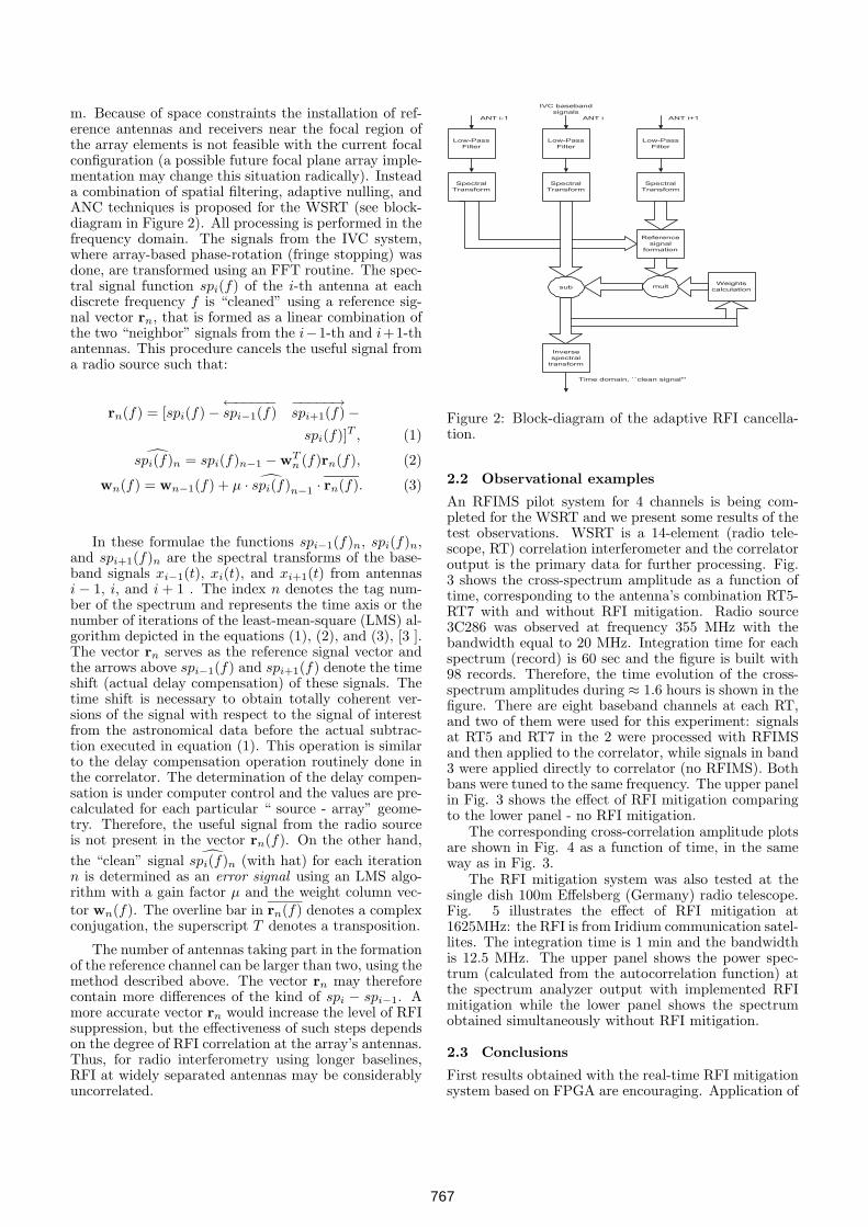
m. Because of space constraints the installation of ref-erence antennas and receivers near the focal region ofthe array elements is not feasible with the current focalconfiguration (a possible future focal plane array imple-mentation may change this situation radically). Insteada combination of spatial filtering, adaptive nulling, andANC techniques is proposed for the WSRT (see block-diagram in Figure 2). All processing is performed in thefrequency domain. The signals from the IVC system,where array-based phase-rotation (fringe stopping) wasdone, are transformed using an FFT routine. The spec-tral signal function spi(f) of the i-th antenna at eachdiscrete frequency f is “cleaned” using a reference sig-nal vector rn, that is formed as a linear combination ofthe two “neighbor” signals from the i−1-th and i+1-thantennas. This procedure cancels the useful signal froma radio source such that:
rn(f) = [spi(f) −←−−−−−spi−1(f)
−−−−−→spi+1(f) −
spi(f)]T , (1)̂spi(f)n = spi(f)n−1 − wT
n (f)rn(f), (2)
wn(f) = wn−1(f) + µ · ̂spi(f)n−1 · rn(f). (3)
In these formulae the functions spi−1(f)n, spi(f)n,and spi+1(f)n are the spectral transforms of the base-band signals xi−1(t), xi(t), and xi+1(t) from antennasi − 1, i, and i + 1 . The index n denotes the tag num-ber of the spectrum and represents the time axis or thenumber of iterations of the least-mean-square (LMS) al-gorithm depicted in the equations (1), (2), and (3), [3 ].The vector rn serves as the reference signal vector andthe arrows above spi−1(f) and spi+1(f) denote the timeshift (actual delay compensation) of these signals. Thetime shift is necessary to obtain totally coherent ver-sions of the signal with respect to the signal of interestfrom the astronomical data before the actual subtrac-tion executed in equation (1). This operation is similarto the delay compensation operation routinely done inthe correlator. The determination of the delay compen-sation is under computer control and the values are pre-calculated for each particular “ source - array” geome-try. Therefore, the useful signal from the radio sourceis not present in the vector rn(f). On the other hand,the “clean” signal ̂spi(f)n (with hat) for each iterationn is determined as an error signal using an LMS algo-rithm with a gain factor µ and the weight column vec-tor wn(f). The overline bar in rn(f) denotes a complexconjugation, the superscript T denotes a transposition.
The number of antennas taking part in the formationof the reference channel can be larger than two, using themethod described above. The vector rn may thereforecontain more differences of the kind of spi − spi−1. Amore accurate vector rn would increase the level of RFIsuppression, but the effectiveness of such steps dependson the degree of RFI correlation at the array’s antennas.Thus, for radio interferometry using longer baselines,RFI at widely separated antennas may be considerablyuncorrelated.
Low-PassFilter
Low-PassFilter
Low-PassFilter
SpectralTransform
SpectralTransform
SpectralTransform
Referencesignal
formation
Weightscalculationsub
Inversespectral
transform
mult
Time domain, ``clean signal'''
IVC basebandsignals
ANT i-1 ANT i ANT i+1
Figure 2: Block-diagram of the adaptive RFI cancella-tion.
2.2 Observational examples
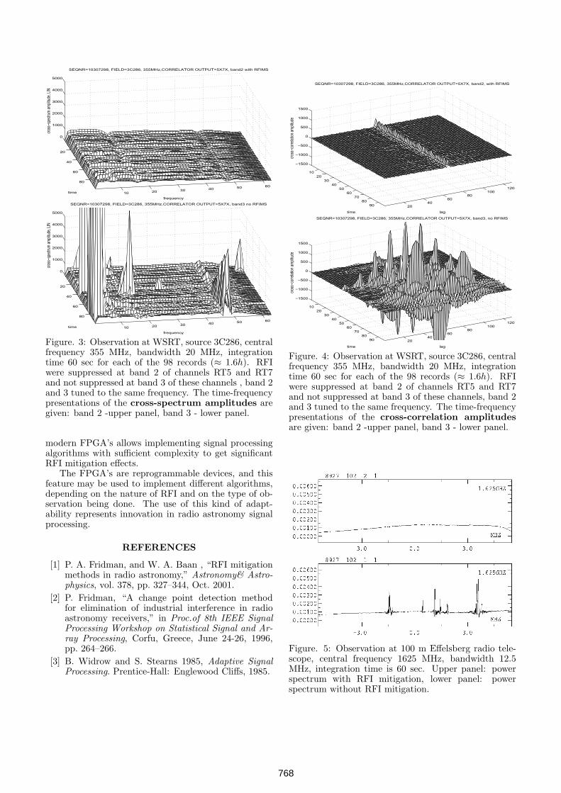
An RFIMS pilot system for 4 channels is being com-pleted for the WSRT and we present some results of thetest observations. WSRT is a 14-element (radio tele-scope, RT) correlation interferometer and the correlatoroutput is the primary data for further processing. Fig.3 shows the cross-spectrum amplitude as a function oftime, corresponding to the antenna’s combination RT5-RT7 with and without RFI mitigation. Radio source3C286 was observed at frequency 355 MHz with thebandwidth equal to 20 MHz. Integration time for eachspectrum (record) is 60 sec and the figure is built with98 records. Therefore, the time evolution of the cross-spectrum amplitudes during ≈ 1.6 hours is shown in thefigure. There are eight baseband channels at each RT,and two of them were used for this experiment: signalsat RT5 and RT7 in the 2 were processed with RFIMSand then applied to the correlator, while signals in band3 were applied directly to correlator (no RFIMS). Bothbans were tuned to the same frequency. The upper panelin Fig. 3 shows the effect of RFI mitigation comparingto the lower panel - no RFI mitigation.
The corresponding cross-correlation amplitude plotsare shown in Fig. 4 as a function of time, in the sameway as in Fig. 3.
The RFI mitigation system was also tested at thesingle dish 100m Effelsberg (Germany) radio telescope.Fig. 5 illustrates the effect of RFI mitigation at1625MHz: the RFI is from Iridium communication satel-lites. The integration time is 1 min and the bandwidthis 12.5 MHz. The upper panel shows the power spec-trum (calculated from the autocorrelation function) atthe spectrum analyzer output with implemented RFImitigation while the lower panel shows the spectrumobtained simultaneously without RFI mitigation.
2.3 Conclusions
First results obtained with the real-time RFI mitigationsystem based on FPGA are encouraging. Application of
767
20
40
60
80
10 20 30 40 50 60
0
1000
2000
3000
4000
5000
SEQNR=10307298, FIELD=3C286, 355MHz,CORRELATOR OUTPUT=5X7X, band2 with RFIMS
frequency
time
cros
s−sp
ectru
m a
mpli
tude
, LIN
20
40
60
80
10 20 30 40 50 60
0
1000
2000
3000
4000
5000
SEQNR=10307298, FIELD=3C286, 355MHz,CORRELATOR OUTPUT=5X7X, band3 no RFIMS
frequency
time
cros
s−sp
ectru
m a
mpli
tude
, LIN
Figure. 3: Observation at WSRT, source 3C286, centralfrequency 355 MHz, bandwidth 20 MHz, integrationtime 60 sec for each of the 98 records (≈ 1.6h). RFIwere suppressed at band 2 of channels RT5 and RT7and not suppressed at band 3 of these channels , band 2and 3 tuned to the same frequency. The time-frequencypresentations of the cross-spectrum amplitudes aregiven: band 2 -upper panel, band 3 - lower panel.
modern FPGA’s allows implementing signal processingalgorithms with sufficient complexity to get significantRFI mitigation effects.
The FPGA’s are reprogrammable devices, and thisfeature may be used to implement different algorithms,depending on the nature of RFI and on the type of ob-servation being done. The use of this kind of adapt-ability represents innovation in radio astronomy signalprocessing.
REFERENCES
[1] P. A. Fridman, and W. A. Baan , “RFI mitigationmethods in radio astronomy,” Astronomy& Astro-physics, vol. 378, pp. 327–344, Oct. 2001.
[2] P. Fridman, “A change point detection methodfor elimination of industrial interference in radioastronomy receivers,” in Proc.of 8th IEEE SignalProcessing Workshop on Statistical Signal and Ar-ray Processing, Corfu, Greece, June 24-26, 1996,pp. 264–266.
[3] B. Widrow and S. Stearns 1985, Adaptive SignalProcessing. Prentice-Hall: Englewood Cliffs, 1985.
1020
3040
5060
7080
90 2040
6080
100120
−1500
−1000
−500
0
500
1000
1500
lag
SEQNR=10307298, FIELD=3C286, 355MHz,CORRELATOR OUTPUT=5X7X, band2, with RFIMS
time
cros
s−co
rrelat
ion a
mpli
tude
1020
3040
5060
7080
90 2040
6080
100120
−1500
−1000
−500
0
500
1000
1500
lag
SEQNR=10307298, FIELD=3C286, 355MHz,CORRELATOR OUTPUT=5X7X, band3, no RFIMS
time
cros
s−co
rrelat
ion a
mpli
tude
Figure. 4: Observation at WSRT, source 3C286, centralfrequency 355 MHz, bandwidth 20 MHz, integrationtime 60 sec for each of the 98 records (≈ 1.6h). RFIwere suppressed at band 2 of channels RT5 and RT7and not suppressed at band 3 of these channels, band 2and 3 tuned to the same frequency. The time-frequencypresentations of the cross-correlation amplitudesare given: band 2 -upper panel, band 3 - lower panel.
Figure. 5: Observation at 100 m Effelsberg radio tele-scope, central frequency 1625 MHz, bandwidth 12.5MHz, integration time is 60 sec. Upper panel: powerspectrum with RFI mitigation, lower panel: powerspectrum without RFI mitigation.
768