Embed Size (px)
Citation preview

10/16/2009
1
Radio over Fiber -An Optical TechniqueAn Optical Technique for Wireless Access
X i F dXavier FernandoRyerson Communications Lab
Toronto, Canadahttp://www.ee.ryerson.ca/~fernando
Motivation

10/16/2009
2
Digital information modulates the light signal in binary (on/off) or M ary manner
Digital Fiber Optic Links
binary (on/off) or M-ary manner
IthI1
P(t)
I
Optical Power
(P)
Example:Most current networks such as SONET,Ethernet, GPON, EPON are digital
Driving Current (I)I(t)
t
tI2
Radio over Fiber (ROF) Links
Radio frequency (analog) waveform (with embedded baseband information)embedded baseband information) continuously modulates the light wave
also referred to as Microwave Photonic Links
E lExamples:CATVSatellite base station linksFiber-Wireless systems

10/16/2009
3
ROF based Fiber-Wireless (Fi-Wi) Access Network
A More Practical Architecture
C ll S li iCell SplittingOvercoming shadows
Fiber sharing?
Multiplexing ?
Use existing fiber ?

10/16/2009
4
Fi-Wi Architecture
• Optical fibers transmit the RF signal between central-base station (CBS) and low power Radio Access Point (RAP).
• The RAP then transmits/receive the RF signal to customer units over the air.
• The RAPs only implement optical to RF conversion and RF to optical conversion.p
• No DSP at RAP to keep it simple
IF over fiber is also sometimes considered, but needs up/down conversion
Fi-Wi SystemMakes the air-interface shorterThis enables truly broadband access by reducing y y g
multi path delay spread (ISI) and often offering line of sight links
Enables Micro/Pico cellular architecture at low costThis increases frequency reuse and boostThis increases frequency reuse and boost
network capacity
Reduce power consumption and size of the portable units (especially for 4G)

10/16/2009
5
Fi-Wi System
Enables rapid deployment (Sydney Olympics example)
Provides coverage to special areas likeUnderground tunnels, mines, subway stations
Highways and railway lines
Potential to use existing fiber
Ideal for mm-wave bands2/1 Loss
Fi-Wi for 4G
• 4G promises 100 Mb/s to 1 Gb/s over air
• Peak RF power is proportional to bit rate timesPeak RF power is proportional to bit rate times (carrier frequency2.6 ) [Adachi].
• Example– If 8 kb/s needs 1W power at 2GHz, then 100 Mb/s
at 5 GHz will need 135 kW power.
• Impossible with regular hand held devices
• Therefore the cell size should be significantly reduced (e.g. from 1000 m 34 m radius)

10/16/2009
6
Why Fiber?• Lowest attenuation 0.2 dB/km at 1.55 µm band.
This is much smaller than attenuation in any other cablecable – The attenuation is independent of the modulation frequency
– Much greater distances are possible without repeaters
• Highest Bandwidth (broadband)– Single Mode Fiber (SMF) offers the lowest dispersion
highest bandwidth up to several tens of GHzhighest bandwidth up to several tens of GHz
• Low Cost for fiber itself
• Possibility of using existing dark/dim fiber
History• Fi-Wi concept started in early 1990s. Ortel™.
Motorola ™ were early players.
• Considered for Boston (USA), New Castle (UK) subway coverage
• There was no real need for ROF (and broadband) at that time
• Now there is a renewed interest• Now there is a renewed interest– There is plenty of dark/dim fiber around
– Technology has matured
– Low cost photonic devices and high cost spectrum

10/16/2009
7
Sydney Olympics 2000 Example• Telstra’s Millennium Network used ~1.5
million km fibermillion km fiber
• Delivered audio, video, and data from the Olympic Games to the world.
• 24 hours a day for sixty days,
• The Millennium Network reached fourThe Millennium Network reached four billion people at any time, with an estimated total of 25 billion people. (http://literature.agilent.com/litweb/pdf/5988-4221EN.pdf)
Sydney Olympics Cont…
BritecellTM
> 500 Remote Antennae Over 500,000 wireless callsOver 500,000 wireless calls Multi operator system (3 GSM operators) Multi standard radio (900/1800 MHz) Dynamic allocation of network capacity In building and external Pico cells

10/16/2009
8
ROF for MIMOBeyond 3G initiative in China code named
FUTURE Multiple antennas in a single ROF cell willMultiple antennas in a single ROF cell will
allow multiple-input multiple-output (MIMO) transmission technology to be applied(http://www.china-cic.org.cn/english/digital%20library/200412/10.pdf)
Multi System Possibility
Both WCDMA and WLAN interfaces supported by one antenna • Within Pico cell Wi-Fi access• Within Micro cell high-speed WCDMA access• Out of Micro cell regular WCDMA access

10/16/2009
9
Th ROF Li k The ROF Link Basics
Closer Look of Fi-Wi Link
Baseband Data
Baseband-RFModulation
RF-Optical Modulation
Central Base
Station
Y
Single Mode Fiber
Optical - RF Demodulation
Gain
BPF
Antenna
200 THz1 8 GHRadio Access
Two Channels in series
200 THz1.8 GHz
RF-Baseband Demodulation
YBaseband
Data
Access
Point
Portable Unit
10/16/2009
10
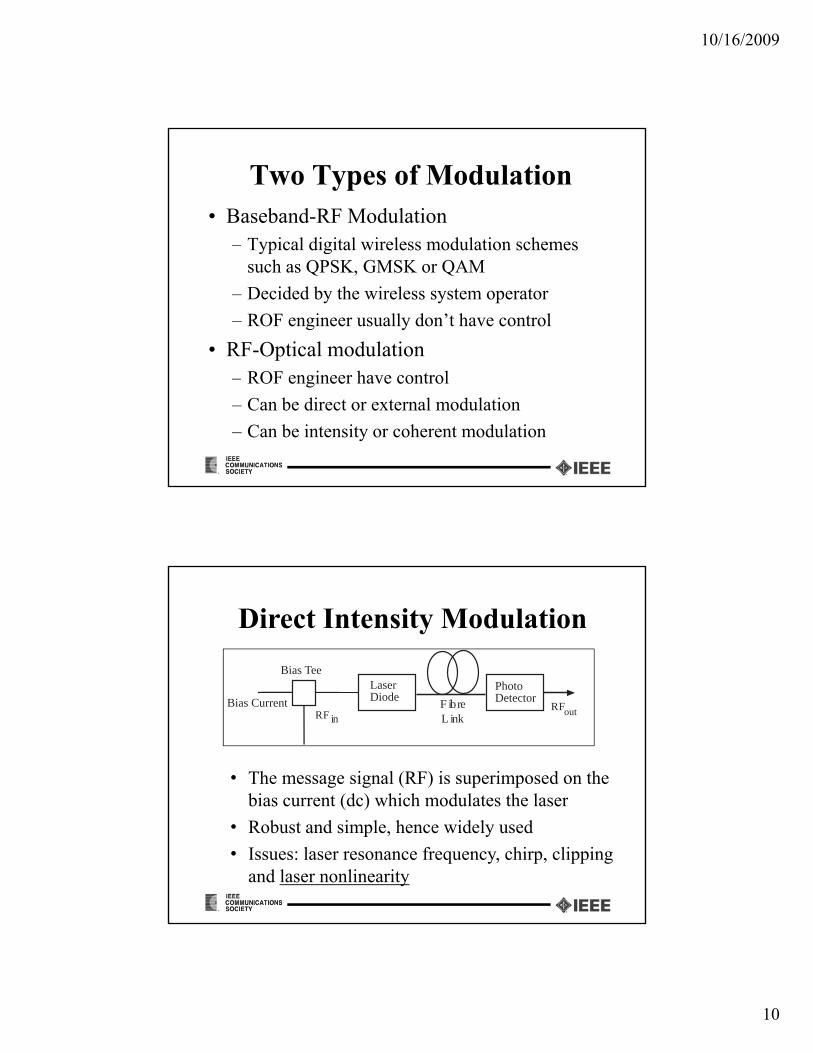
Two Types of Modulation• Baseband-RF Modulation
– Typical digital wireless modulation schemesTypical digital wireless modulation schemes such as QPSK, GMSK or QAM
– Decided by the wireless system operator
– ROF engineer usually don’t have control
• RF-Optical modulation– ROF engineer have control
– Can be direct or external modulation
– Can be intensity or coherent modulation
Bias TeeLaser Photo
Direct Intensity Modulation
RF in
Bias Current
LaserDiode
PhotoDetectorF ibre
L inkRFout
• The message signal (RF) is superimposed on the bias current (dc) which modulates the laserbias current (dc) which modulates the laser
• Robust and simple, hence widely used
• Issues: laser resonance frequency, chirp, clipping and laser nonlinearity

10/16/2009
11
Direct Intensity Modulation of Laser Diode
Optical Output
Saturation
(nonlinearit )(mW)
Linear Region
(nonlinearity)
Light Output
Input Current
(mA)
Bias Current
Spontaneous Emission (nonlinear)
Threshold
(Clipping)
Modulating Signal (RF)
• Fabry-Perot Laser– Multiple longitudinal modes
Types of Lasers
– Medium noise and distortion
• Distributed Feed Back Laser– Single longitudinal mode
– Low noise and distortion
• Vertical Cavity Surface Emitting Lasersy g– Simple coupling to fiber
– Mainly short wavelength
– Higher noise and distortion

10/16/2009
12
External Intensity Modulation
EOM PhotoLaser
• Modulation and light generation are separatedOff h id b d idth t 60 GH
EOM
RF in
PhotoDetector
LaserDiode
F ibreL ink
RFout
• Offers much wider bandwidth up to 60 GHz• More expensive and complex• Used in high end systems (no chirp)• Still nonlinearity is a concern
Mach Zehnder Modulator
Vb
RF
λo λo
VM(t)
Laser
P (t) (1+πVM (t)
Mach-Zehnder Modulator
Pout,op(t)
o λo
Photodetector
Popt,inquadrature
Popt,in
Lt
)
Vπ
VM(t) = Vb + VRF cos (ωt)
Pout,op(t) = (1+cosVπ2
0VM(t)
)

10/16/2009
13
Mach Zehnder Modulator• Incoming light is split into two paths
El i fi ld li d h hi h• Electric field applied to one path which introduces a phase shift mπ
• When m is – odd constructive interference
– even destructive interference at the output– even destructive interference at the output
• Traveling wave type electrodes improve bandwidth
Electro Absorption Modulator
An EAM modulates the light by a change in the absorption spectrum caused by anthe absorption spectrum caused by an applied electric field
EAM can operate with much lower voltages at very high speed (tens of gigahertz)
EAM can work as a photo detector for theEAM can work as a photo detector for the downlink and modulator for uplink

10/16/2009
14
Electro Absorption Modulator
• An ideal single device RAP
• Demonstrated byDemonstrated by British Telecom
• Very low power pico cells
Transfer function H(f) of the fiber
Optical Carrier
Modulation
Depth ~ 0.2
RF Spectrum in the Fiber
o=1310 nm
0 02 nm (3 6 GHz)
(f)
RF Subcarrier
RF Bandwidth
Fiber dispersion will rotate the phase of sidebands
0.02 nm = (3.6 GHz)
H(f) = exp[-j()l(f-fo)2];l: length, :Dispersion factor

10/16/2009
15
Spectrum with 5 GHz RF Sidebands
Sub Carrier MultiplexingUnmodulated (main) carrier
f2f2
• SCM Frequency division multiplexed (FDM)
FrequencySub-carriers
f1f1
f0
SCM Frequency division multiplexed (FDM) multiple RF carriers
• Each modulating RF is a sub-carrier• Unmodulated optical signal is the main carrier

10/16/2009
16
The Fiber
Fiber Dispersion• Typical intensity modulation creates double
sideband transmit carrier spectrum
• Fiber group velocity dispersion (GVD) causes phase shift between the USB and LSB
• At specific fiber distance lf the phase shift b 180o id b d ll tican be 180o sideband cancellation
• Several single side band schemes are developed, especially at mm-wave bands

10/16/2009
17
Fiber Dispersion & Sideband Cancellation at λ = 1550 nm
0 . 9
1
0 . 3
0 . 4
0 . 5
0 . 6
0 . 7
0 . 8
rmal
ized
Rec
eive
d R
F P
ower
f = 2 . 4 G H z f = 9 0 0 M H z
LengthFiber
22 ])([cos)(
fl
cf flklP
1 00
1 01
1 02
1 03
1 04
0
0 . 1
0 . 2
F ib e r L e n g t h [ k m ]
Nor
Frequency
nAttenuatio)(
cf
PhotodiodesThis convert the received light wave signal to
electrical current (O/E)( )• Positive-Intrinsic-Negative (pin) photodiode
– No internal gain– Robust and widely used
• Avalanche Photo Diode (APD)A i t l i f M d t lf lti li ti– An internal gain of M due to self multiplication
– Requires high reverse bias voltage (~40V)– Expensive and used only in high end systems

10/16/2009
18
Noise/Distortions in ROF Links
• Modal distortion– only in multimode fiber
• Attenuation – depends on wavelength
• GVD – Group velocity distortion
Noise in Photo Detector
)(2 22 MFBMqIi pQ F(M): APD noise figure q = electron chargeq gM = Avalanche Gain Ip: Mean detected currentB = Bandwidth
Quantum noise is proportional to mean optical powerLarge unmodulated carrier results in high shot noise
Quantum (Shot) Noise
LBT RTBKi /42 Thermal noiseDepends on the load resistance RL and constant
10/16/2009
19
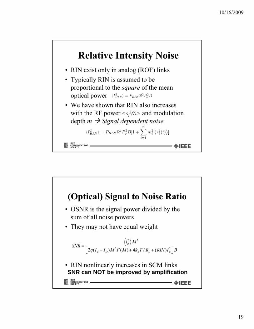
Relative Intensity Noise• RIN exist only in analog (ROF) links
T i ll RIN i d b• Typically RIN is assumed to be proportional to the square of the mean optical power
• We have shown that RIN also increases with the RF power <si
2(t)> and modulationwith the RF power si (t) and modulation depth m Signal dependent noise
(Optical) Signal to Noise Ratio • OSNR is the signal power divided by the
sum of all noise powers
• They may not have equal weight
2 2
2 22 ( ) ( ) 4 / ( )
p
D B L
i MSNR
q I I M F M k T R RIN I B
• RIN nonlinearly increases in SCM links
( ) ( ) / ( )p D B L pq k N
SNR can NOT be improved by amplification

10/16/2009
20
Optical Amplifier?
• Optical amplifier amplifies sidebands plus carrier
Also add noise (ASE)• Also add noise (ASE)
• Not very useful in single wavelength ROF links
• High power carrier will flood the detector
• Useful in WDM ROF links
Power Budget of Power Budget of Fi-Wi Links

10/16/2009
21
Closer Look of Fi-Wi Link
Baseband Data
Baseband-RFModulation
RF-Optical Modulation
Central Base
Station
Y
Single Mode Fiber
Optical - RF Demodulation
Gain
BPF
Antenna
200 THz1 8 GHRadio Access
Two Channels in series
200 THz1.8 GHz
RF-Baseband Demodulation
YBaseband
Data
Access
Point
Portable Unit
RAP Bridges Two Channels
���������
�� ���
����������������� ���� ����
���
����� ���� ���� ����
• The Radio Access Point amplifies and retransmits the RF signal (downlink)C l ti SNR i th f t SNR’
OSNR ESNR
• Cumulative SNR is the sum of two SNR’s– Optical channel SNR (OSNR)– Wireless (electrical) channel SNR (ESNR)

10/16/2009
22
Impedance Matching Loss
Impedance Matching is an issue at both the transmitter and receiver– Forward biased Laser has very low impedance
– Reverse biased photodiode has very high impedance
– Resistive impedance matching gives wide bandwidth but high loss (~ 40 dB – ORTEL)bandwidth, but high loss ( 40 dB ORTEL)
– Reactive impedance matching techniques (with L,C) reduce loss and also bandwidth (~10-20 dB)
Loss in the Optical Link
• Loss due to E/O and O/E Conversion– 39 dB with resistive matching [*Ortel]39 d w t es st ve atc g [ O te ]– 20 dB with reactive matching
• Fiber loss (α dB/km) increases with length (l) and appears twice in the electrical domain
fop lL )(2dB20
• Optical noise is added at the RAP where, the signal is lowest
fop )(

10/16/2009
23
Cumulative SNR
• The noise is added twice (at the optical and wireless receivers) where the signal is weak.
• The overall SNR is the weighted sum of the two SNRs and smaller than the smallest SNR.
��
��
��� �
���
�������
��� ���
���
��
�� � ��
�� ����� ����
����� ���
����

10/16/2009
24
Cumulative SNR
• Lop – depends on wavelength - α(λ) dB/km222• nop – optical link noise =
• Gop = Gwl – Amplifier Gain
• Lwl – Path loss in the air interface
• OSNR – SNR at the RAP
SNR SNR t th t bl
222thRINsh III
• SNR – SNR at the portable
op
L
G
OSNRSNR
10/101
Concatenated Channel
• Week signal plus noise is amplified and transmitted at the RAPtransmitted at the RAP
• More noise added in the air and at the portable receiver
• Both signal and noise go through wireless channel loss O i l d di i di h S• Optical and Radio noises dictate the SNR
• Acceptable SNR at the cell boundary dictates the cell size

10/16/2009
25
OSNR Vs Fiber Length
25
30Shot Noise OnlyRIN OnlyShot and RIN
0
5
10
15
20
OS
NR
(dB
)
B = 1.25 MHz, RIN = -155 dB/Hz, R=0.75 A/W, α=0.5 dB/km
0 5 10 15 20 25 30−15
−10
−5
0
Fiber Length (km)
Some Observations
• There is an inverse relationship between the radio cell size and the fiber lengththe radio cell size and the fiber length
• Closer to the RAP (when Lwl < Gop), the optical link noise dominates
YY
Lwl < Gop
Wireless channel noise and MUI dominates when Lwl > Gop

10/16/2009
26
25
30
B)
Optical Receiver Amp. Gain Vs Wireless Path Loss
Higher OSNR Larger radio cells for the same Gop
10
15
20
um O
ptic
al A
mpl
ifier
Gai
n R
equi
red
(in d
B)
OSNR = 12dB
OSNR = 15dB
OSNR = 20dB
10 15 20 250
5
L (in dB)
Min
imu
Required SNR at Cell Boundary = 10dB
L = Path loss to the cell boundary
Minimum Amplification at RAP
45
50
in d
B)
Gop decreases with OSNR and cell size
25
30
35
40
imum
Opt
ical
Am
plifi
er G
ain
Req
uire
d (in
L = 15dB
L = Path loss to the cell boundary
10 10.5 11 11.5 12 12.5 13 13.5 14 14.5 1515
20
OSNR (in dB)
Min
im
L = 10dB
L = 12dB
Required SNR at Cell Boundary = 10dB

10/16/2009
27
Radio Cell Size Vs SNR
70
75
80
ary
(dB
)
OSNR = 15 dB
55
60
65
70
axim
um L
oss
L A
llow
ed a
t Cel
l Bou
ndar
y OSNR = 15 dB
OSNR = 12 dB
OSNR = 10 dB
0 5 10 1545
50
Required SNR at Cell Boundary (dB)
Max
i
Optical Amplifier Gain Gop
= 30dB
Some Observations
• Loss and noise in the ROF link plays significant role in overall system performanceg y p
• Wider bandwidth RF signal collects more noise in the ROF link (CDMA)
• Lower modulation depth results in higher unnecessary quantum noise
• RIN nonlinearly increases in SCM systems
• E/O and O/E conversion loss reduction is key area of research

10/16/2009
28
Nonlinear Increment in Noise
−115
−110Variation of Noise floor with Carrier power
Span 10 MHz, RBW = 100 kHz, VBW = 300 Hz
−130
−125
−120
−115
ured
Noi
se P
ower
(dB
m/H
z) Span 10 MHz, RBW = 100 kHz, VBW = 300 Hz
Atten 0 dB, Ref Level = −10 dBm
With optical link
−10 −5 0 5−145
−140
−135
Carrier Power (dBm)
Mea
sur
Without optical link
Nonlinear Nonlinear Distortion in ROF

10/16/2009
29
Nonlinear Distortion• Nonlinear distortion in the ROF links arises
due to:due to:– E/O Conversion at either laser diode or at Mach-
Zehnder modulator
– Nonlinearity of the receiver RF amplifier
• The former is of more crucial
• The nonlinearity combined with multipath propagation in the air interface creates problems
Laser Diode Nonlinearity
• Rate equationsOpt. Power
dN
dt
IA
qVact
N
n
go(NNog)(1S)S
dS
dt go(NNog)(1S)
1
p
S
N
n
Current
Po
IbIth
Large number of device dependant parameters make direct modeling very difficult [Vankwilkelberge et. al. 89]
CurrentIbIth
10/16/2009
30
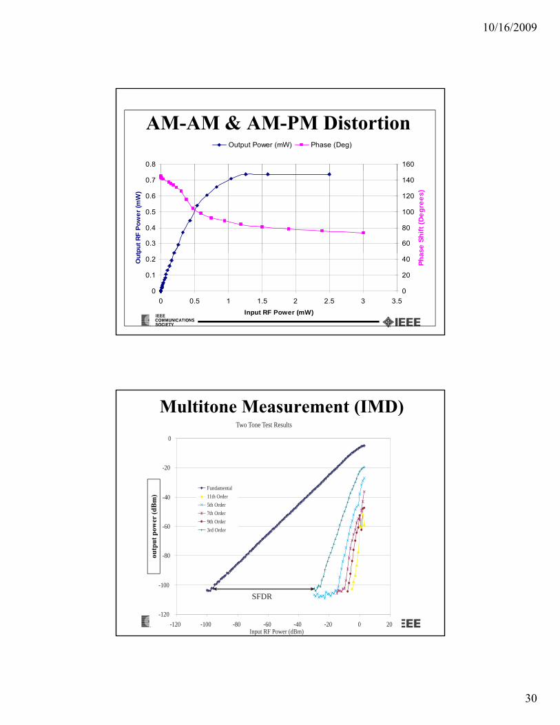
AM-AM & AM-PM Distortion
0.8 160
Output Power (mW) Phase (Deg)
0.3
0.4
0.5
0.6
0.7
tpu
t R
F P
ow
er
(mW
)
60
80
100
120
140
se
Sh
ift
(De
gre
es
)
0
0.1
0.2
0 0.5 1 1.5 2 2.5 3 3.5
Input RF Power (mW)
Ou
t
0
20
40
Ph
a
Multitone Measurement (IMD)Two Tone Test Results
-20
0
-80
-60
-40
Fundamental
11th Order
5th Order
7th Order
9th Order
3rd Order
utp
ut
pow
er (
dB
m)
-120
-100
-80
-120 -100 -80 -60 -40 -20 0 20Input RF Power (dBm)
SFDR
ou

10/16/2009
31
Large linear dynamic range is required i ll i h li k
Nonlinearity Issues
especially in the reverse linkMultipath fading & shadowing (40-60 dB)Varying user distance (d) from RAPVarying path loss (d-1.5 ~ d-4.0)Varying number of usersVarying number of usersRF envelope fluctuation (peak to average ratio)
Some Approaches to Solve NLD
• Opto/Electronic linearization approaches targeting the laser (mostly for analog CATV g g ( y glinks).– Solving rate equations.
– Laser circuit models.
– Device Dependency
• Other techniques
Laser is not the only concern in ROF
• Other techniques.– Modified channel assignment.
– Automatic gain controllers (not for AM-PM)
– Baseband DSP Solutions*
10/16/2009
32
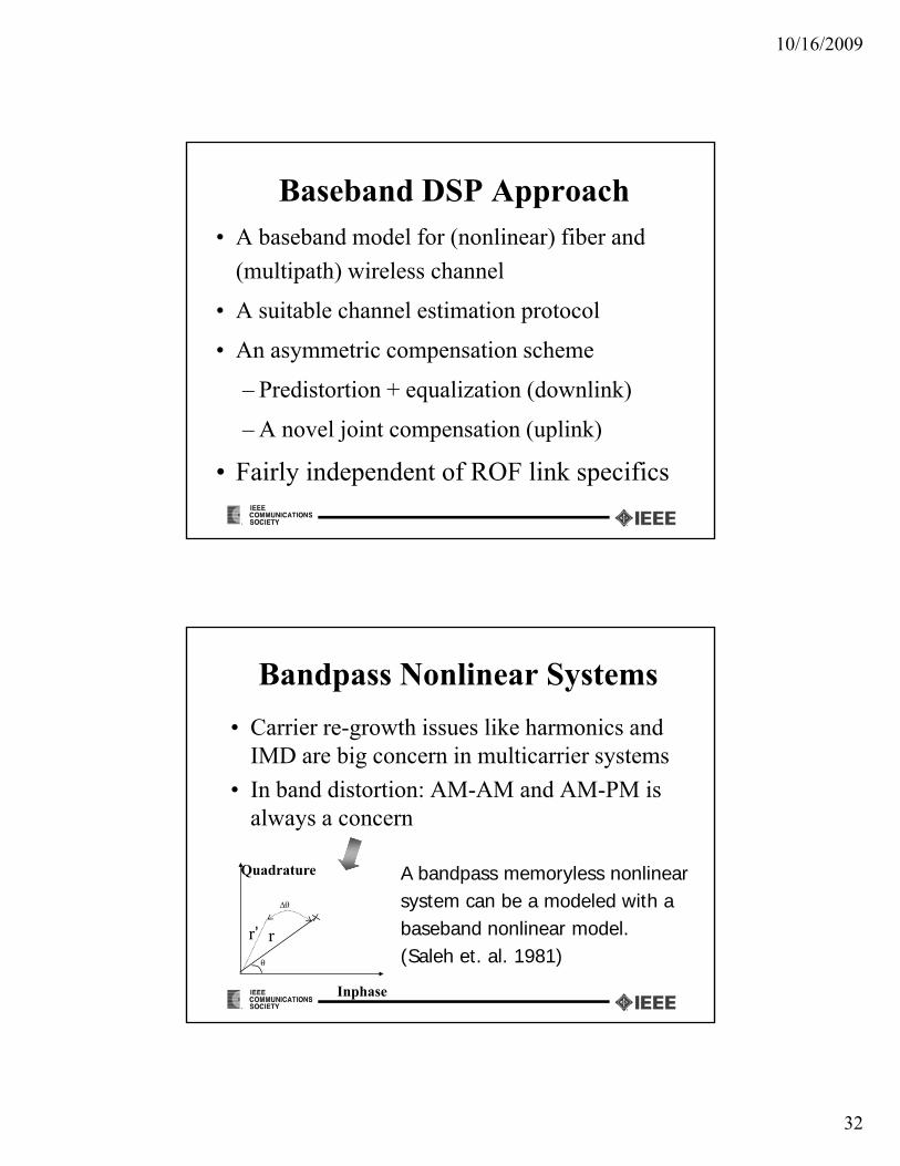
Baseband DSP Approach• A baseband model for (nonlinear) fiber and
(multipath) wireless channel(multipath) wireless channel
• A suitable channel estimation protocol
• An asymmetric compensation scheme
– Predistortion + equalization (downlink)
– A novel joint compensation (uplink)
• Fairly independent of ROF link specifics
Bandpass Nonlinear Systems
• Carrier re-growth issues like harmonics and IMD are big concern in multicarrier systemsIMD are big concern in multicarrier systems
• In band distortion: AM-AM and AM-PM is always a concern
Quadrature A bandpass memoryless nonlinear
r
Inphase
r’
system can be a modeled with a baseband nonlinear model. (Saleh et. al. 1981)

10/16/2009
33
Signal Processing Preliminaries
All the impairments would primarily result in amplitude and phase distortionresult in amplitude and phase distortionof the vector modulated symbols plus noise only.
I
Q Q
I
With adequate sampling rate baseband DSP can be deployed for nonlinear distortion compensation.
Fiber-Wireless Uplink Estimation
h(n)
v(n)PN Sequence
Noise
Linear Part Nonlinear Part
h(n) F(.)x(n) q(n) r(n)
q
(Wireless Channel) (Optical Channel)
The cross correlation:
Rrx(s) {h(s) + higher order terms}

10/16/2009
34
v(n)A1(.) w1(n)
Fiber-wireless Uplink Estimation...
Linear Part Nonlinear Part
h(n)x(n)
q(n)
v(n)
r(n)A2(.)2
w2(n)
PN Seq.
Noise
Al(.)l wl(n)
Rrx(s) = Rw1x(s) + Rw2x(s) + ... + Rwlx
(s)
Cross correlation terms
Fiber Wireless Uplink Estimation…
1. Estimate the linear impulse response h(n)
– By projecting each cross-correlation term into a different
subspace
2. Estimate the polynomial coefficients Ai
– Q(n) is estimated from using h(n)
– R(n) is known
– Ai are determined by QR decomposition methodq(n) r(n)
Ai qi(n)
10/16/2009
35
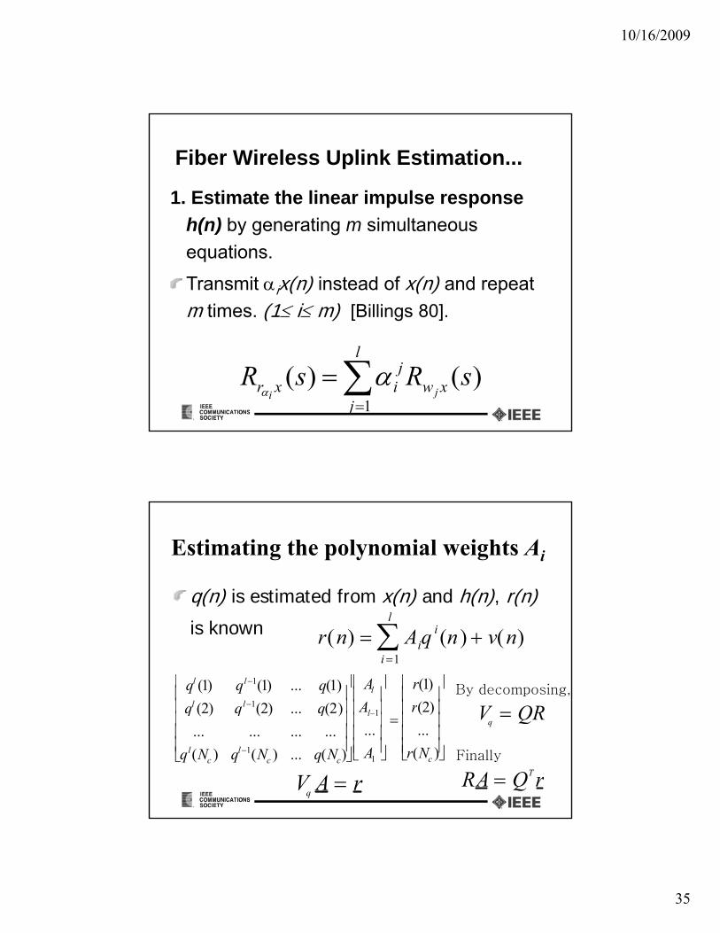
Fiber Wireless Uplink Estimation...
1. Estimate the linear impulse response
h( ) b ti i lth(n) by generating m simultaneous
equations.
Transmit ix(n) instead of x(n) and repeat
m times. (1 i m) [Billings 80].
)()(1
sRsR xw
l
j
jixr ji
Estimating the polynomial weights Ai
q(n) is estimated from x(n) and h(n), r(n)
is known r(n) Aii 1
l
q i (n ) v(n)
ql (1) ql1(1) ... q(1)
ql (2) ql1(2) ... q(2)
Al
Al 1
r(1)
r(2)
V QR
By decomposing,
q (2) q (2) ... q(2)
... ... ... ...
ql(Nc ) ql1(Nc ) ... q(Nc)
l1
...
A1
( )
...
r(Nc )
VqA r
Vq QR
RA QT rFinally

10/16/2009
36
h(n) F(.)q(n)
v(n)
A Unified Compensation
Linear Part Nonlinear Part
h(n) F(.)x(n) q(n)r(n)
PLF ε x(n)FFF
PolynomialFilter
PLFz(n)
ε
FBFLinear Filter
Linear Filter
x(n)
FFF
Hammerstein System
BER Performance of the HDFE

10/16/2009
37
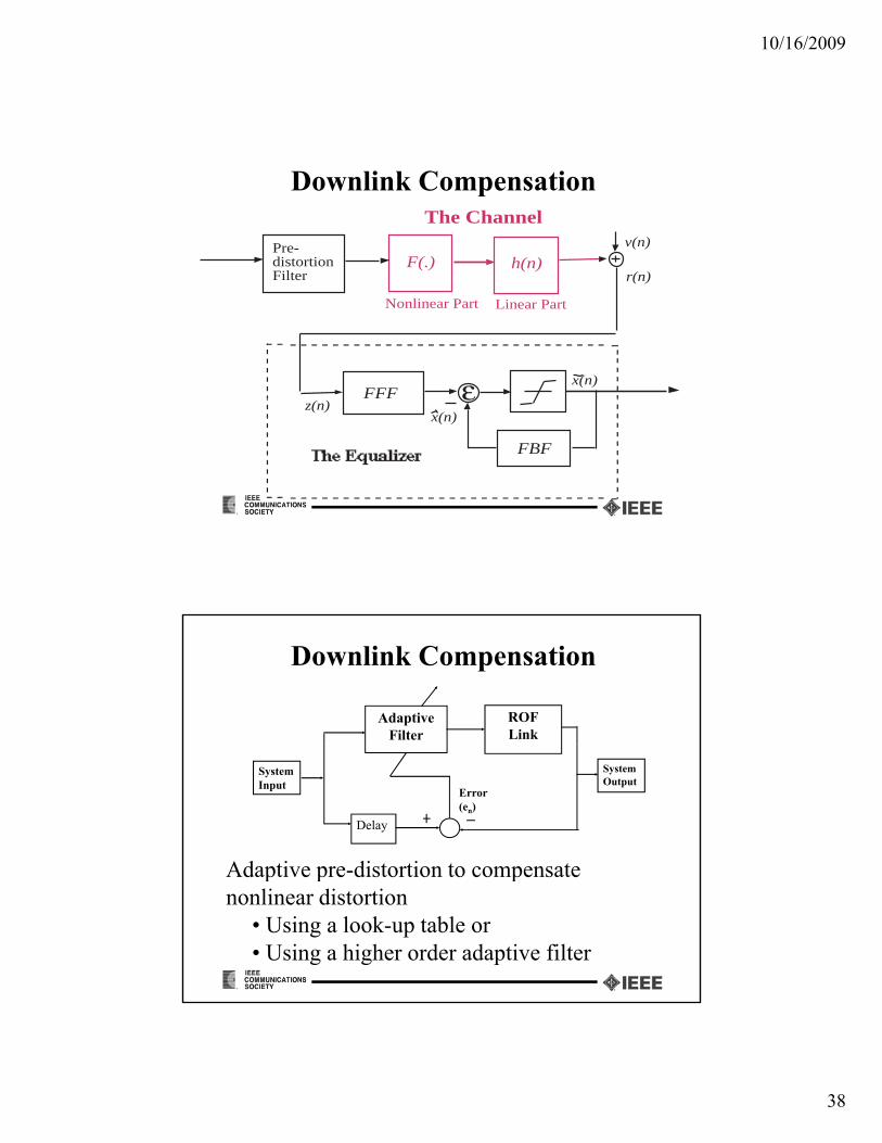
Downlink Compensation
ROFLink
Adaptive Filter
SystemInput
Delay
Error (en)
SystemOutput
Adaptive predistortion to compensateAdaptive predistortion to compensate nonlinear distortion
• Using a look-up table or• Using a higher order adaptive filter
Predistortion• The linearization can be done predistortion.
• The principle of predistortion is to create direct proportionality between the input signal and the optical outputInput Signal Optical Signal
Predistortion Laser Diode
• Amplitude predistortion can NOT completely solve saturation
• It can improve the dynamic range to some extend
10/16/2009
38
Downlink Compensation
F(.)v(n)
r(n)
The Channel
Pre-distortionFilter
h(n)
Linear PartNonlinear Part
F(.)r(n)
distortionFilter
h(n)
z(n)ε x(n)
FFFz(n)
ε
FBF
x(n)
FFF
Downlink Compensation
ROFLink
Adaptive Filter
SystemInput
Delay
Error (en)
SystemOutput
Adaptive pre-distortion to compensateAdaptive pre distortion to compensate nonlinear distortion
• Using a look-up table or• Using a higher order adaptive filter

10/16/2009
39
Filter output without back-off
Amplitude Predistortion
No predistortion
Out
put a
mpl
itud
e
Predistortion with 30% back-off
Input amplitude
Advantages of the DSP Solution• Separate compensation for the dynamic wireless
channel and the static fiber channel is possiblechannel and the static fiber channel is possible
• Multiple users can share the same nonlinearity compensation
• Proposed solution has Modular architecture
• No modification is preferred in the portable unitNo modification is preferred in the portable unit
• Asymmetric distribution of complexity is desirable
• Device independent (adaptive) approach is possible

10/16/2009
40
Multisystem Multisystem ROF
Multisystem ROF• When multiple RF signals are transmitted over
fiber for Fi-Wi support multitude of issues:fiber for Fi-Wi support, multitude of issues:– Noise, loss and power budget for each system
– Nonlinearity and dynamic range issue for individual systems
– Cross coupling among RF signals due to li inonlinearity
– Added RIN due to multiple carriers
– Other (MAC layer) issues

10/16/2009
41
WLAN and WCDMA
AirRadio Access Point Uplinknwl
SNR1up,wcdma
SNR1up,wlan
SNR2up,wcdma
SNR2up,wlan
Air Interface
E/OO/E
nop
Radio Access Point
Lop
1
p
L (r )wl i
1
L (r )wl w lan
1nwl
Gdown,wl an
WLANMS
WCDMAMS
nwl
WLAN
WCDMA
WLAN
Gup,wc dma
Gup,wlan
CENTRAL
BASE
STATION
Pre-amplifierIncluded
Downlinknop
Lop
1
nwl
WCDMA
E/O O/E
Gdow n, wcdma
SNR1down,wlan SNR2down,wlan
SNR1down,wcdma SNR2down,wcdma
Design Issues• Up/down link amplifier gain for each system
• Modulation depth for each system• Modulation depth for each system
• Cumulating noise and SNR for both systems (that depend on bandwidth, loss etc.)
• RF power and radio cell size for each system
• Nonlinear coupling among these systems• Nonlinear coupling among these systems
• Other wireless system issues (CDMA, OFDM etc)

10/16/2009
42
Some Expressions
Cumulative Optical Modulation Index
WCDMA Uplink
iwcdma
wlan
m
mT
I d d f T iwcdma,
Nonlinear DistortionLimit
Independent of T

10/16/2009
43
WLAN UplinkDepends on T
iwcdma
wlan
m
mT
,
Nonlinear DistortionLi itLimit
Optical Signal Optical Signal Processing
10/16/2009
44
Microwave Photonics for ROF Systems
• Photonic generation of microwave signals
• All-Optical up/down conversion of RF signals
• All-Optical microwave filtering and signal processing
• Optical single sideband (OSSB) modulation
• Carrier power reduction
All Optical Microwave Signal Processing
• Bandpass low pass and high pass tuneable• Bandpass, low pass and high pass, tuneable microwave photonic filters can be realized by – Optical delay lines (similar to tap delay line
electrical filter)
– Wavelength selective elements such fiber Bragg grating, waveguide arrays

10/16/2009
45
Fiber Bragg Gratings
FP-FBG Fabrication
Ultraviolet Radiation
248 nmAmplitude Mask
Phase mask technique
Amplitude mask is a
Phase Mask
-1st
order
Optical Fiber
1st order (40%)
1st order (40%)
-1st
order
double Sinc mask
Phase mask is a diffractive optical element
Fiber is a hydrogen l d d i l d fib
Diffracted Beams
(40%)
EDFA
0th
order (< 5%)
OSA
0th
order (< 5%)
(40%) loaded single mode fiber
ΛBragg = Λmask/2
10/16/2009
46
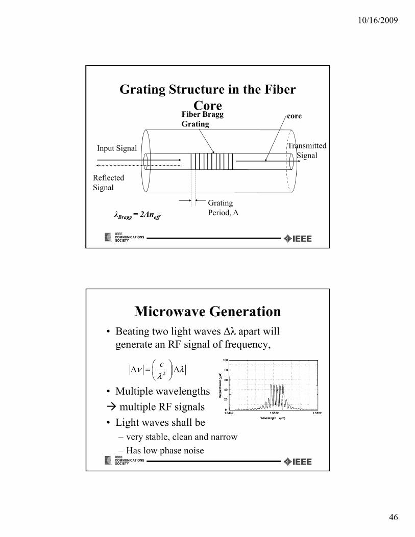
Grating Structure in the Fiber Core
Fiber Bragg GratingGrating
Input Signal
Reflected Signal
Transmitted Signal
Signal
Grating Period, ΛλBragg = 2Λneff
Microwave Generation• Beating two light waves Δλ apart will
generate an RF signal of frequency,g g q y,
• Multiple wavelengths
multiple RF signals
2
c
p g
• Light waves shall be – very stable, clean and narrow
– Has low phase noise

10/16/2009
47
Microwave Generation with single DBR Laser
• Reflectivity wavelength = 1533.773 nm
• 3 dB Bandwidth = 0.637 nm
• Laser Energy = 195 mJ
• Grating 1 Length 1 = 5 mm
• Grating 2 Length = 2.5 mm
• Writing Time – Grating 1 = 5 min 44 s
• Writing Time – Grating 2 = 2 min 10 s
• Phase mask wavelength = 1530.6 nm
980 nm Pump Laser
C
R
1530 nmPhoto‐Detector
WDMFiber Laser
980 nm
1530nm/980nm
WCA
Microwave Generation with single DBR Laser
Laser spectra with two Longitudinal modes Generated Microwave 858.8 MHz,
Bandwidth 10.681 kHz

10/16/2009
48
Up/Down Conversion
• Can be achieved using combinations of various nonlinear elements like:– Optical phase modulators
– Intensity modulators
– Dispersive fiber
– Optical amplifiers (fiber/Semiconductor)– Optical amplifiers (fiber/Semiconductor)
• Power loss during conversion is a concern
All-Optical DemultiplexingCellularMicrocell
900 MHz
Radio-over-Fiber (ROF)
MHz
2.4 GHz
Electrical Multiplexer
Optical Demultiplexer
Cellular Base
Stations
Laser Diode
Y
LNA
photodiodeRAP
WLAN
Y
LNAphotodiode RA
PRAP: Radio Access Point
Wireless LAN

10/16/2009
49
All-Optical Demultiplexing
• Any RF subcarrier can be accessed at any point in the ROF network (suits PON)
• Unnecessary loss, noise and distortion due to O/E and E/O conversion are avoided.
• The photo detector can have low bandwidth (matched to only one subcarrier)(matched to only one subcarrier)
• Significant cost reduction
Narrowband FBG• FBG-based narrow bandpass filters can be designed
using two methods if the FBG length is limited between 15 mm and 30 mm.
1. Induce a pi-phase in the middle of the FBG, which will create a narrow pass band in the middle of the FBG stop band.
-3 dB bandwidth as low as 0.5 pm
But high insertion loss
2. Induce two FBGs with identical wavelength. This method results in multiple resonant peaks in the stop band.
Low insertion loss

10/16/2009
50
• A highly reflective filter with a bandwidth in the sub-Pico meter range was imprinted using two highly reflective FBGs, which formed a resonator
FBG-Based Resonance Filter
which formed a resonator
• The overall length of the filter is 28mm
FBG1 FBG2
12 mm 12 mm
4 mm H2-loaded SMF-28λB λB
Resonance Filter• The stop bandwidth of the FBG was ~ 0.3 nm at -3 dB and five resonant
peaks were created.
• The bandwidth of the resonant peak is determined by the length of theThe bandwidth of the resonant peak is determined by the length of the resonator and the reflectivity of the FBG.
-15
-10
-5
0
mis
sio
n [d
B]
(a)
-30
-25
-20
1536.2 1536.3 1536.4 1536.5 1536.6 1536.7 1536.8
Wavelength [nm]
Tra
nsm
~73 pm

10/16/2009
51
Filter Transfer FunctionThe spectrum of resonant peak (black trace) was obtained by scanning the sideband over a 2 GHz range at 4 MHz per step. The red trace was the calculated resonant spectrum from a l bplaner Fabry-Perot resonator.
The filter has a bandwidth of
120 MHz at -3 dB360 MHz at -10 dB1.5GHz at -20 dB
The insertion loss is 0.8 dB at the resonant peak.
Filter is polarization sensitive
Optical Spectra at MZM Output
(a) Output of the MZM when the DC bias is tuned to non-linear region(b) When DC bias is tuned to linear region(b) Sideband are not visible at this bias condition

10/16/2009
52
Demux Experiment
Filtered Spectrum
The FBG filter alignedto the LSB of the 900 MHZ peak

10/16/2009
53
Selectivity of the Demultiplexer
Frequency Separation of the Filter• The BER performance of 900 MHz signal at the filter output
as the 2nd subcarrier was swept from 450 MHz to 1.1 GHz
• The BER level at 50 MHz separation is 2.72x10⁻⁶

10/16/2009
54
Carrier SuppressionNarrow optical filters can be used to suppress unmodulated
carrierIn this case sensitivity improvement ~7 dB
Single FBG based SCM Demux
Important Parameters:1 Freq separation (f f )1. Freq. separation (fi - fj )2. Slope of the FBG filter3. Flatness of the filter top4. Modulation depth
EX: If f2 = 2.4 GHz, filter BW < 38.6 pm
FBG filter
f1 f2 f3
filter BW 38.6 pm

10/16/2009
55
Transmission Characteristics of an FBG Measured by Agilent 8164A
1553.8 1553.9 1554 1554.1 1554.2 1554.3 1554.4
Wavelength (nm)
8 5
-8
-7.5
-7
-6.5
-6
Loss
(dB
)
Center λ = 1554.184 nmΔλ = 37 pm 3 dB
-10
-9.5
-9
-8.5
Spectrum with 2.4 GHz RF Signal

10/16/2009
56
Coherent ROF Coherent ROF Systems
Coherent ROF System architecture
L SMF at 1330 3 dB directional coupler with Laser source:DFB, Nd:YAG
RF
E t l
RF
nm or 1550 nm
balance detectorOptical combiner with signal detector
Polarization
Direct Modulation
ExternalModulation
or
Local Oscillator (DFB Laser)
Polarization Control Receiver

10/16/2009
57
Coherent Systems…
• Amplitude or Angle Modulation (PM, FM) is possible with coherent systemsis possible with coherent systems
• Angle modulation has higher Spurious Free Dynamic Range (SFDR) to handle large dynamic range requirement of the air
• External coherent modulation gives power g pgain while direct coherent modulation gives power loss
Coherent Systems…• Relative intensity noise (RIN) is proportional to the
square of the mean optical power.q p p
• A balance coherent receiver (with closely matched photodiodes) can cancel majority of the RIN
• Optical signal sideband (OSSB) can be easily done with coherent systems [6]
• External modulation give 70 GHz and directExternal modulation give 70 GHz and direct modulation gives 20 GHz electrical bandwidths respectively [2]

10/16/2009
58
Coherent Systems…• Angle modulation systems have phase noise
• Phase noise cancellation schemes could further increase SFDR in angle modulation
• Potential system to employ angle modulation with external phase modulator
• However, coherent systems:– Are more expensivep
– Need phase locked receivers
– Need very stable and narrow line width lasers
RF over MMF• Multimode Fiber (MMF)
– Predominant in-building backbones– High coupling efficiency – 90%– Simple coupling technique – butt coupling
– But low bandwidth (typically 500 MHz.km at 1300 nm) due to modal dispersion
– Hence IF over MMF is dominant
• RF over MMF– low installation cost combined with low complexity

10/16/2009
59
WDM ROFWill be the future
Existing dim fibers can be effectively usedExisting dim fibers can be effectively used
Emerging FTTx networks can carry additional SCM RF wavelengths
• Very high linearity requirements
• High isolation requirements for WDMHigh isolation requirements for WDM de-multiplexers
• Cost considerations
Conclusions• Radio over Fiber is an attractive approach for
wideband wireless accessFib h l b d id h• Fiber has ample bandwidth
• Lots of existing dim/dark fiber• Supporting multiple standards is possible• Major concerns are
– High loss and noise due to concatenated channelsHigh loss and noise due to concatenated channels– Nonlinear distortion and limited dynamic range
• Some emerging areas like coherent modulation will improve the situation

10/16/2009
60
References[1] An analytic and experimental comparison of direct and external modulation in analog fiber-optic links
Cox, C.H., III; Betts, G.E.; Johnson, L.M.; Microwave Theory and Techniques, IEEE Transactions on , Volume: 38 Issue: 5 , May 1990 Page(s): 501 –509
[2] Direct-detection analog optical linksCox, C., III.; Ackerman, E.; Helkey, R.; Betts, G.E.; Microwave Theory and Techniques, IEEE Transactions on , Volume: 45 Issue: 8 , Aug. 1997Page(s): 1375 –1383
[3] Dynamic range of coherent analog fiber-optic links Kalman, R.F.; Fan, J.C.; Kazovsky, L.G.; Lightwave Technology, Journal of , Volume: 12 Issue: 7 , July 1994 Page(s): 1263 –1277
[4] On the design of optical fiber based wireless access systems..Fernando X. N.; Anpalagan A.;WINCORE laboratory, Ryerson University, Toronto
[5] Optically coherent direct modulated FM analog link with phase noise canceling circuit T l R F t STaylor, R.; Forrest, S.; Lightwave Technology, Journal of , Volume: 17 Issue: 4 , April 1999 Page(s): 556 –563
[6] Technique for optical SSB generation to overcome dispersion penalties in fiber-radio systemsSmith, G. H.; Novak D.; Ahmed Z;
[7] Phase noise in coherent analog AM-WIRNA optical linkTayor R.; Poor H. V.; Forrest Stephen;


![5-2 High-Spectral Density Multiplexing Trans- mission and ... · gle optical fiber [1]-[4]. To increase the optical-spectral efficiency, an optical frequency inter-leaving technique](https://img.pdfslide.net/doc/110x75/5ed940fc6714ca7f47696c50/5-2-high-spectral-density-multiplexing-trans-mission-and-gle-optical-fiber.jpg)