Embed Size (px)
Citation preview
www.codanradio.com
Radio Repeater Systems
TRAINING GUIDE

RADIO REPEATER SYSTEM | TRAINING GUIDE
Page i
Radio Repeater System
Training Guide

TRAINING GUIDE | RADIO REPEATER SYSTEM
Page ii
© 2013 Codan Limited. No part of this guide may be reproduced, transcribed, translated into any language or transmitted in any form whatsoever without the prior written consent of Codan Limited.
CODAN™, NGT™, Easitalk™, CIB™ and CALM™ are trademarks of Codan Limited. Other brand, product, and company names mentioned in this document are trademarks or registered trademarks of their respective holders.
Comshel © is a copyright name of Sinclair Radio Laboratories Ltd.The maps used in this document are based on information taken fromthe National Topographic System map sheets numbered 92-H, 92-I and92-I/6 ©. Her Majesty the Queen in Right of Canada with permission ofEnergy, Mines and Resources Canada..Antenna and duplexer data are copyright catalogue reference materialused with permission of Sinclair Radio Laboratories Ltd.
The English version takes precedence over any translated versions.
NOTE
DOCUMENT REVISION DEFINITION
Codan Radio Communications43 Erie Street, Victoria, BCCanada V8V [email protected]
Toll Free Canada and USA:Phone: 1-800-664-4066Fax: 1-877-750-0004
International:Phone: 250-382-8268Fax: 250-382-6139
PRINTED IN CANADA
Document Number:Revision:
Revision Date:
TG-0023-0-0September 2013
Documentation uses a three-level revision system. Each element of the revision number signifi es the scope of change as described in the diagram below.
Major Revisions: The result of a major change to
product function, process or requirements.
Minor Revisions: The result of a minor change to
product, process or requirements.
Editorial Revisions: The result of typing corrections or
changes in formatting, grammar or wording.
1-0-0
Three-level revision numbers start at 1-0-0 for the fi rst release. The appropriate element of the revision number is incremented by 1 for each subsequent revision, causing any digits to the right to be reset to 0.
For example:If the current revision = 2-1-1 Then the next major revision = 3-0-0If the current revision = 4-3-1 Then the next minor revision = 4-4-0If the current revision = 3-2-2 Then the next editorial revision = 3-2-3
Document revision history is provided at the back of the document.

RADIO REPEATER SYSTEM | TRAINING GUIDE
Page iii
Pete Lunness is a member of the Applied Science Technologists & Technicians of British Columbia, has a Diploma in Electronics Engineering Technology from Camosun College and a Certifi cate in Adult and Continuing Education from the University of Victoria.
Pete has been at Daniels / Codan since 1996, working in engineering, sales and customer support, and has been instructing technical training courses since 1998.
ABOUT THE AUTHOR
Codan Radio Communications is a leading international designer and manufacturer of premium communications equipment for High Frequency (HF) and Land Mobile Radio (LMR) applications. We’ve built our reputation for reliability and customer satisfaction over 50 years in radio communications, in some of the toughest conditions on the planet.
For over 50 years Codan has provided customers in North America and internationally with highly reliable Base Stations and Repeaters that are environmentally robust to operate in rugged and extreme temperature conditions where low current consumption (solar powered) is a key requirement.
Codan is a pioneering member of the P25 Digital standard, for radio system interoperability between emergency response governmental organizations, providing enhanced functionality and encryption. Our products operate between 29 - 960 MHz and are available in a variety of Base Station and Repeater confi gurations for two way voice and mobile data applications.
Our self-servicing customers range from Forestry and National Park services through Police and Fire departments and on to Utility and Transportation groups. Our products have been deployed in every imaginable situation from the Antarctic to Hawaiian mountaintops to Alaska, enabling respondents to Forest Fires, Ground Zero rescue and routine patrols.
Codan is an industry leader in Analog and P25 radio systems design. We offer modular rack-mounted Base Stations and Repeaters capable of operating in Low Band VHF,VHF AM , VHF FM, UHF FM, 700 MHz, 800 MHz, 900 MHz
ABOUT CODAN RADIO COMMUNICATIONS
On August 7th, 2012 - Codan Limited (ASX: “CDA”) announced the acquisition of Daniels Electronics Limited, a leading designer, manufacturer and supplier of land mobile radio communications (LMR) solutions in North America. The acquisition of Daniels delivers on Codan’s stated strategy of growing market share and diversifying its radio communications product offering. Codan Limited designs, manufactures and markets a diversifi ed range of high value added electronic products, with three key business divisions; radio communications, metal detection and mining technology.
DANIELS ELECTRONICS IS NOW CODAN RADIO COMMUNICATIONS

TRAINING GUIDE | RADIO REPEATER SYSTEM
Page iv
(1) Bullington K., “Radio Propagation Fundamentals”, B.S.T.J. 36, pp. 593-625; May 1957
(2) Bullington K., “Radio Propagation for Vehicular Communications,” in IEEE Transactions on Vehicular Technology, vol. VT-26, No.4, November, 1977
(3) VHF and UHF Propagation, Datafi le Bulletin 10003-1, Communications Products Department, General Electric Company, Lynchburg, Virginia, July 1977
(4) Stewart Alex G., “Low-Current Repeaters Suit Remote Site Needs”, in Mobile Radio Technology, Vol.8, Issue 9, pp. 10-24; September 1990
(5) Peasland T.H.S., Stewart Alex G., “The Development of Simple Wide Area VHF Radio Systems”, Unpublished report to Communications Canada, 1983
(6) Peasland T.H.S., Stewart Alex G., Phillips J.M., “Radio Repeater System Applications Manual”, Daniels Electronics Instruction Manual, 1992
(7) Singer Edward N., “Land Mobile Radio Systems, 2nd Edition”, Prentice Hall, Inc., 1994
One of your best sources of information is the various equipment manufacturers. Most have prepared reference material for their products.
In no event will Codan Ltd. be liable for direct, indirect, special, incidental or consequential damages resulting from the use of any information contained within this document.
BIBLIOGRAPHY
RADIO REPEATER SYSTEM | TRAINING GUIDE
Page v
ContentsChapter 1: Repeater System Basics ......................................1
Introduction ................................................................................................1Determining Frequencies and Frequency Band(s) ....................................3Coverage Area and Site Location ..............................................................4
Chapter 2: Repeater System Confi gurations .........................9Determining Confi guration .........................................................................9Linked Repeater Systems ........................................................................ 11CTCSS ..................................................................................................... 15Other Confi gurations ................................................................................ 15
Chapter 3: Repeater System Equipment ............................. 17Repeater / Base Station ........................................................................... 17Antennas .................................................................................................. 20Duplexers, Multicouplers and Combiners ................................................ 24Power supplies ......................................................................................... 25Accommodation ....................................................................................... 28
Chapter 4: Installation and Maintenance ............................. 31Installation Hints and Techniques............................................................. 31Maintenance ............................................................................................ 32Lightning Protection ................................................................................. 33Interference .............................................................................................. 34
Appendix A: Drawing Coverage Maps ................................. 35
Appendix B: Drawing Path Profi les ...................................... 39
Appendix C: Calculating Path Loss ...................................... 43
Appendix D: Calculating Signal Levels ................................ 45
Appendix E: Mobile Coverage Tests .................................... 51
Appendix F: Examples of Antenna Data .............................. 55
Appendix G: Examples of Duplexer Data ............................ 61
Appendix H: Examples of Cable & Connector Losses ......... 65
Appendix I: Blank Worksheets ............................................. 67
Appendix J: Glossary of Terms ............................................ 73

TRAINING GUIDE | RADIO REPEATER SYSTEM
Page vi
This Page Intentionally Left Blank
RADIO REPEATER SYSTEM | TRAINING GUIDE
Chapter 1: Repeater System Basics Page 1
CHAPTER 1: REPEATER SYSTEM BASICS
Guidelines to Plan and Implement a Simple, Effective and Reliable Radio Communications System
INTRODUCTION
This document will familiarize you with radio system design, focusing on repeaters and base stations. This document gives you the basics to design simple radio systems. Professional help should be obtained for more complex radio system designs.
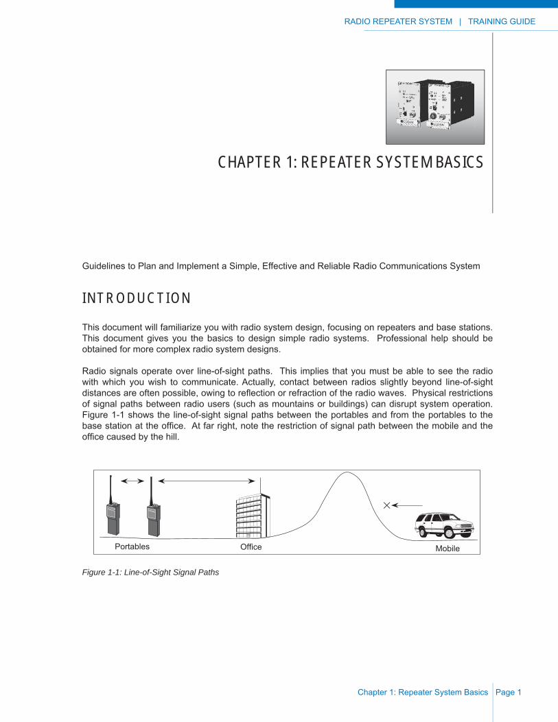
Radio signals operate over line-of-sight paths. This implies that you must be able to see the radio with which you wish to communicate. Actually, contact between radios slightly beyond line-of-sight distances are often possible, owing to refl ection or refraction of the radio waves. Physical restrictions of signal paths between radio users (such as mountains or buildings) can disrupt system operation. Figure 1-1 shows the line-of-sight signal paths between the portables and from the portables to the base station at the offi ce. At far right, note the restriction of signal path between the mobile and the offi ce caused by the hill.
Figure 1-1: Line-of-Sight Signal Paths
Portables MobileOffice
TRAINING GUIDE | RADIO REPEATER SYSTEM
Chapter 1: Repeater System BasicsPage 2
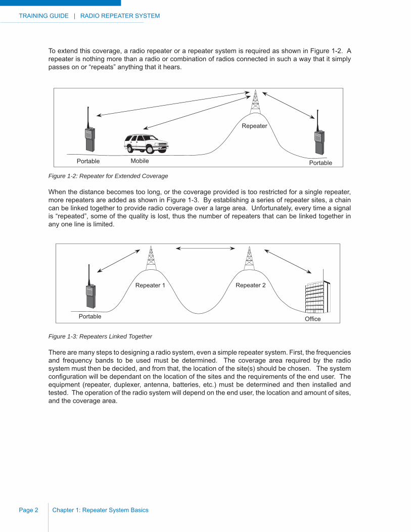
To extend this coverage, a radio repeater or a repeater system is required as shown in Figure 1-2. A repeater is nothing more than a radio or combination of radios connected in such a way that it simply passes on or “repeats” anything that it hears.
Figure 1-2: Repeater for Extended Coverage
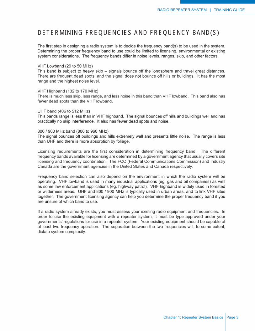
When the distance becomes too long, or the coverage provided is too restricted for a single repeater, more repeaters are added as shown in Figure 1-3. By establishing a series of repeater sites, a chain can be linked together to provide radio coverage over a large area. Unfortunately, every time a signal is “repeated”, some of the quality is lost, thus the number of repeaters that can be linked together in any one line is limited.
Figure 1-3: Repeaters Linked Together
There are many steps to designing a radio system, even a simple repeater system. First, the frequencies and frequency bands to be used must be determined. The coverage area required by the radio system must then be decided, and from that, the location of the site(s) should be chosen. The system confi guration will be dependant on the location of the sites and the requirements of the end user. The equipment (repeater, duplexer, antenna, batteries, etc.) must be determined and then installed and tested. The operation of the radio system will depend on the end user, the location and amount of sites, and the coverage area.
Mobile
Repeater
Portable Portable
Portable
Repeater 1 Repeater 2
Office
RADIO REPEATER SYSTEM | TRAINING GUIDE
Chapter 1: Repeater System Basics Page 3
DETERMINING FREQUENCIES AND FREQUENCY BAND(S)
The fi rst step in designing a radio system is to decide the frequency band(s) to be used in the system. Determining the proper frequency band to use could be limited to licensing, environmental or existing system considerations. The frequency bands differ in noise levels, ranges, skip, and other factors.
VHF Lowband (29 to 50 MHz)This band is subject to heavy skip – signals bounce off the ionosphere and travel great distances. There are frequent dead spots, and the signal does not bounce off hills or buildings. It has the most range and the highest noise level.
VHF Highband (132 to 170 MHz)There is much less skip, less range, and less noise in this band than VHF lowband. This band also has fewer dead spots than the VHF lowband.
UHF band (406 to 512 MHz)This bands range is less than in VHF highband. The signal bounces off hills and buildings well and has practically no skip interference. It also has fewer dead spots and noise.
800 / 900 MHz band (806 to 960 MHz)The signal bounces off buildings and hills extremely well and presents little noise. The range is less than UHF and there is more absorption by foliage.
Licensing requirements are the fi rst consideration in determining frequency band. The different frequency bands available for licensing are determined by a government agency that usually covers site licensing and frequency coordination. The FCC (Federal Communications Commission) and Industry Canada are the government agencies in the United States and Canada respectively.
Frequency band selection can also depend on the environment in which the radio system will be operating. VHF lowband is used in many industrial applications (eg. gas and oil companies) as well as some law enforcement applications (eg. highway patrol). VHF highband is widely used in forested or wilderness areas. UHF and 800 / 900 MHz is typically used in urban areas, and to link VHF sites together. The government licensing agency can help you determine the proper frequency band if you are unsure of which band to use.
If a radio system already exists, you must assess your existing radio equipment and frequencies. In order to use the existing equipment with a repeater system, it must be type approved under your governments’ regulations for use in a repeater system. Your existing equipment should be capable of at least two frequency operation. The separation between the two frequencies will, to some extent, dictate system complexity.
TRAINING GUIDE | RADIO REPEATER SYSTEM
Chapter 1: Repeater System BasicsPage 4
COVERAGE AREA AND SITE LOCATION
One of the key components of radio system design is to determine the coverage area required and the location of sites needed to cover that area. An existing radio system may not cover all of the required area, and another repeater may be required. A new repeater can be “linked” to your existing radio system to increase your coverage area. Depending on the location, a radio system can provide coverage of an area with a radius of 5 to 50 kilometers (2 to 30 miles) or even further under ideal conditions.
A repeater or remote base station is usually located at a high site to ensure that the radio system covers all of the area required. The development of low power, high reliability, battery operated radio systems has allowed radio repeaters sites to be located at remote mountain tops and other areas where roads and power lines do not exist. If room is available at the site to erect a building to house the equipment, and to safely land a helicopter, the site could be used for your radio system.
One key to good system planning is good mapping. Topographic (contour) maps 1:250,000 for coverage (as demonstrated earlier), and 1:50,000 for profi les between sites are recommended.
The whole idea of using low-powered, automatic repeater stations (ARS) is to put them where they are required for coverage, and not where it may be most convenient. You now must fi nd a site or sites that will:
i) provide your missing coverage.
ii) provide a location from which a repeater will give a strong signal into your base station (if required).
iii) be accessible by road, trail, or helicopter.
iv) be in a position that will be line-of-sight to the next site (if required).
v) if a second site is necessary, provide the coverage you need, yet not leave coverage overlaps between sites; nor conversely leave an unusable gap in coverage between the two sites.
Whether you plan a remote controlled base station, a repeater, or two (or more) repeaters; mobile coverage maps for each mountain-top site are suggested, as are profi les between sites, and profi les from site(s) to base station(s).

RADIO REPEATER SYSTEM | TRAINING GUIDE
Chapter 1: Repeater System Basics Page 5
If it looks like one repeater will provide your missing coverage you may wish instead to consider using a remote controlled base station as shown in Figure 1-4. This may provide the required coverage but the following items will have to be considered:
a) a site must be available that has power and telephone lines available and is in a location that will provide your coverage needs.
b) there will be an ongoing expense for the remote control lines rented from your telephone company.
c) the phone and power lines may not be reliable.
d) such a site will probably already be occupied leading to possible future problems of access (road closures and maintenance), radio noise and interference from other users (see sketch).
e) road access usually means that there will be a greater possibility of vandalism.
Figure 1-4: Remote Controlled Base Station
Office
Power and telephone lines
Road access
Multi-user mountain-topsite (base station).

TRAINING GUIDE | RADIO REPEATER SYSTEM
Chapter 1: Repeater System BasicsPage 6
To determine if the site you have chosen will cover the required area, a coverage map should be drawn for that site. A coverage map shows the areas that the proposed radio system will effectively cover with line-of–sight paths. Mobile coverage maps are a bit of an “art form” because you have to use your imagination. In spite of this, they end up being quite accurate, and are much less expensive than a fi eld survey. In addition, if more than one site is required, prepare profi les of the path between the sites.A coverage map and path profi le are shown in Figure 1-5. Detailed information about drawing coverage maps is available in appendix A, and detailed information on path profi les can be found in Appendix B.
Figure 1-5: Coverage Map and Path Profi le
Office2020'
3000'
4000'
1000'
Obstructions
Hills Not Obstructing.Signal O.K.
Line-of-sight
Elevation
Plan View
1000
'
2000
'
3000
'
3000
'40
00'
2000' 2000'
Line-of-sight (50 km)
Phillips Creek
Office
Obstructed Path
Portable Poor or no Signal
RADIO REPEATER SYSTEM | TRAINING GUIDE
Chapter 1: Repeater System Basics Page 7
The propagation of radio energy from one point to another is affected by obstacles, both natural and man-made. Much depends on whether the obstacle is totally blocking, or partially blocking the signal path. In the latter case the refl ected signal from the obstacles takes a longer time to reach the receiving antenna than does the direct ray. The result may be distortion, or even total cancellation, of the received signal.
Appendix C details the method of calculating the path loss between sites. Once the path losses are known, simple calculations of losses and gains will provide the signal level which should result on the paths. Appendix D contains instructions for calculating the signal level on a path. Recommended signal levels on your paths are suggested as follows:
i) between repeater sites - a minimum of 20 μV.
ii) repeater site to base station - a minimum of 10 μV.
Discussion with other local users and a trip to the proposed site may also be advantageous, particularly if you also do some tests using a low-powered portable (at the proposed site) to a mobile in the questionable areas. See instructions in Appendix E on mobile coverage tests.
There are other items for consideration, many other factors that are not easily measurable may affect radio signals. Signals may be received beyond line-of-sight, and some obstructions may not completely wipe out signals. On longer paths, you may also gain the advantage of refractive bending of the signal beam which is allowed for by your use of 4/3 earth curvature graph paper. Note however, that as the frequency is increased; refractive bending, although normally downward, will vary (even upward) by atmospheric conditions such as temperature, pressure and relative humidity. At VHF and UHF below 800 MHz this is not normally a problem, although other weather conditions such as heavy sleet or ice storms may reduce your signal levels by up to 20 dB.
Licensing your radio system for use does not automatically give you the legal authority to install equipment on site. Leasing or buying the small plot of land is required. You may fi nd it necessary to work with different governments (federal, municipal, county, state, etc.) to arrange all of your requirements. Most authorities have additional specifi cations that you must meet if your repeater sites are within a specifi ed distance of an operating airport. Painting and lighting of obstructions is one such specifi cation.
Equipment outages at a mountain top environment are often weather related. The equipment is designed to be as reliable as possible and is thoroughly tested before installation but a lightning strike nearby can negate all of that in an instant. Consider carefully before locating your repeater site on a Lightning Peak, or; as we have done in the example, on an Iron Mountain. If not familiar with weather patterns in the area yourself, talk to those that have local knowledge.

TRAINING GUIDE | RADIO REPEATER SYSTEM
Chapter 1: Repeater System BasicsPage 8
This Page Intentionally Left Blank
RADIO REPEATER SYSTEM | TRAINING GUIDE
Chapter 2: Repeater System Confi gurations Page 9
CHAPTER 2: REPEATER SYSTEM CONFIGURATIONS
DETERMINING CONFIGURATION
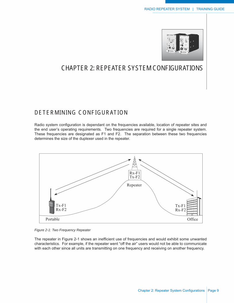
Radio system confi guration is dependant on the frequencies available, location of repeater sites and the end user’s operating requirements. Two frequencies are required for a single repeater system. These frequencies are designated as F1 and F2. The separation between these two frequencies determines the size of the duplexer used in the repeater.
Figure 2-1: Two Frequency Repeater
The repeater in Figure 2-1 shows an ineffi cient use of frequencies and would exhibit some unwanted characteristics. For example, if the repeater went “off the air” users would not be able to communicate with each other since all units are transmitting on one frequency and receiving on another frequency.
Portable
Repeater
Office
Tx-F1Rx-F2
Tx-F1Rx-F2
Rx-F1Tx-F2
TRAINING GUIDE | RADIO REPEATER SYSTEM
Chapter 2: Repeater System Confi gurationsPage 10
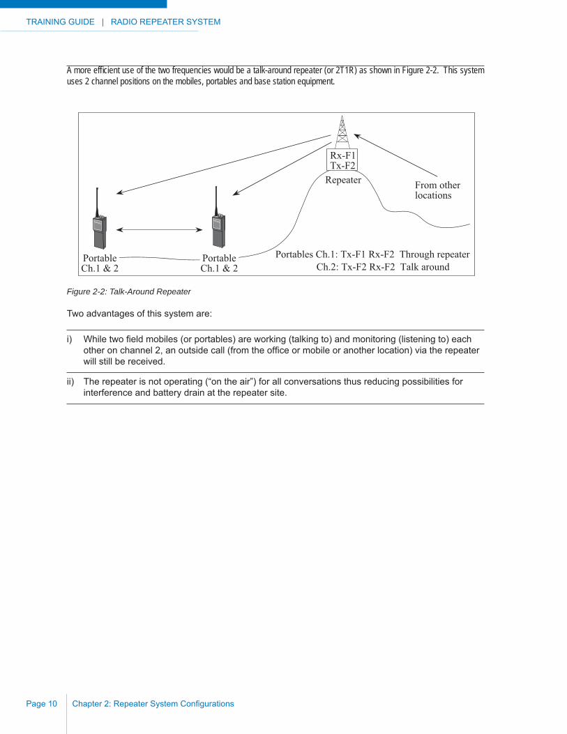
A more effi cient use of the two frequencies would be a talk-around repeater (or 2T1R) as shown in Figure 2-2. This system uses 2 channel positions on the mobiles, portables and base station equipment.
Figure 2-2: Talk-Around Repeater
Two advantages of this system are:
i) While two fi eld mobiles (or portables) are working (talking to) and monitoring (listening to) each other on channel 2, an outside call (from the offi ce or mobile or another location) via the repeater will still be received.
ii) The repeater is not operating (“on the air”) for all conversations thus reducing possibilities for interference and battery drain at the repeater site.
Repeater From otherlocations
Portables Ch.1: Tx-F1 Rx-F2 Through repeaterCh.2: Tx-F2 Rx-F2 Talk around
Rx-F1Tx-F2
PortableCh.1 & 2
PortableCh.1 & 2
RADIO REPEATER SYSTEM | TRAINING GUIDE
Chapter 2: Repeater System Confi gurations Page 11
LINKED REPEATER SYSTEMS
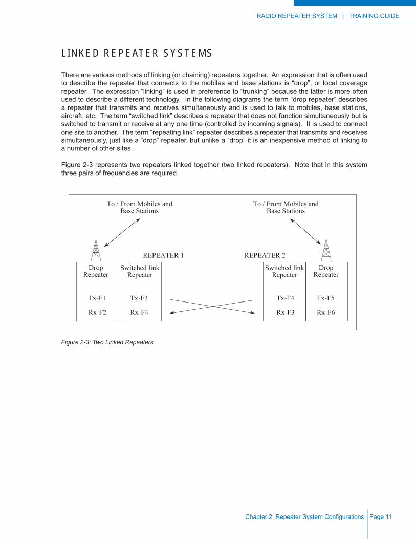
There are various methods of linking (or chaining) repeaters together. An expression that is often used to describe the repeater that connects to the mobiles and base stations is “drop”, or local coverage repeater. The expression “linking” is used in preference to “trunking” because the latter is more often used to describe a different technology. In the following diagrams the term “drop repeater” describes a repeater that transmits and receives simultaneously and is used to talk to mobiles, base stations, aircraft, etc. The term “switched link” describes a repeater that does not function simultaneously but is switched to transmit or receive at any one time (controlled by incoming signals). It is used to connect one site to another. The term “repeating link” repeater describes a repeater that transmits and receives simultaneously, just like a “drop” repeater, but unlike a “drop” it is an inexpensive method of linking to a number of other sites.
Figure 2-3 represents two repeaters linked together (two linked repeaters). Note that in this system three pairs of frequencies are required.
Figure 2-3: Two Linked Repeaters
REPEATER 1 REPEATER 2
To / From Mobiles andBase Stations
To / From Mobiles andBase Stations
DropRepeater
Switched linkRepeater
Tx-F1
Rx-F2
Tx-F3
Rx-F4
DropRepeater
Switched linkRepeater
Tx-F4
Rx-F3
Tx-F5
Rx-F6
TRAINING GUIDE | RADIO REPEATER SYSTEM
Chapter 2: Repeater System Confi gurationsPage 12
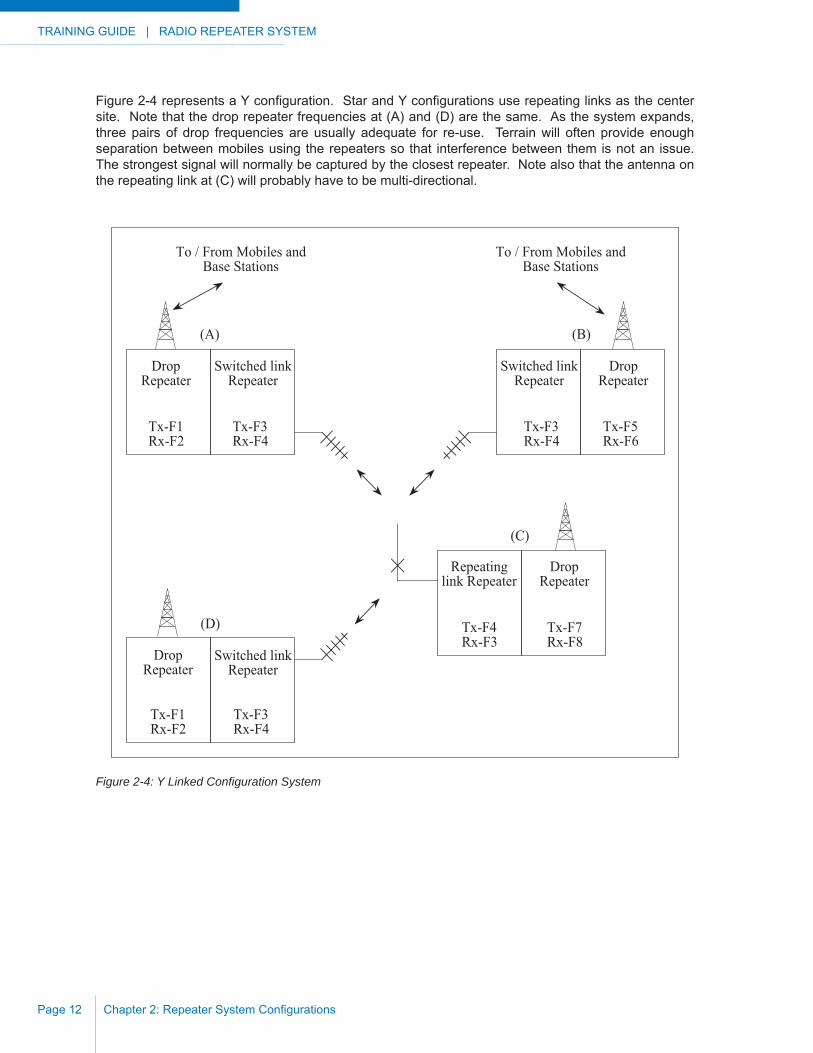
Figure 2-4 represents a Y confi guration. Star and Y confi gurations use repeating links as the center site. Note that the drop repeater frequencies at (A) and (D) are the same. As the system expands, three pairs of drop frequencies are usually adequate for re-use. Terrain will often provide enough separation between mobiles using the repeaters so that interference between them is not an issue. The strongest signal will normally be captured by the closest repeater. Note also that the antenna on the repeating link at (C) will probably have to be multi-directional.
Figure 2-4: Y Linked Confi guration System
To / From Mobiles andBase Stations
To / From Mobiles andBase Stations
DropRepeater
Switched linkRepeater
Tx-F1Rx-F2
Tx-F3Rx-F4
DropRepeater
Switched linkRepeater
Tx-F3Rx-F4
Tx-F5Rx-F6
Repeatinglink Repeater
DropRepeater
Tx-F4Rx-F3
Tx-F7Rx-F8
DropRepeater
Switched linkRepeater
Tx-F1Rx-F2
Tx-F3Rx-F4
(A) (B)
(C)
(D)
RADIO REPEATER SYSTEM | TRAINING GUIDE
Chapter 2: Repeater System Confi gurations Page 13
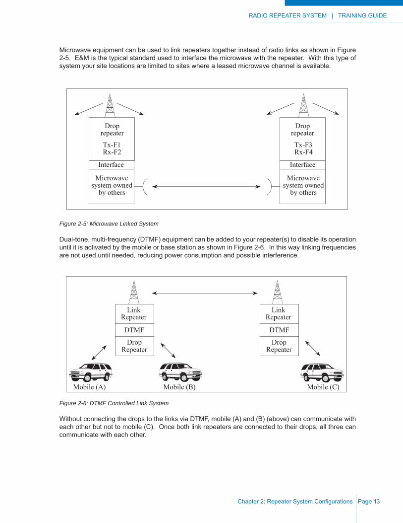
Microwave equipment can be used to link repeaters together instead of radio links as shown in Figure 2-5. E&M is the typical standard used to interface the microwave with the repeater. With this type of system your site locations are limited to sites where a leased microwave channel is available.
Figure 2-5: Microwave Linked System
Dual-tone, multi-frequency (DTMF) equipment can be added to your repeater(s) to disable its operation until it is activated by the mobile or base station as shown in Figure 2-6. In this way linking frequencies are not used until needed, reducing power consumption and possible interference.
Figure 2-6: DTMF Controlled Link System
Without connecting the drops to the links via DTMF, mobile (A) and (B) (above) can communicate with each other but not to mobile (C). Once both link repeaters are connected to their drops, all three can communicate with each other.
Droprepeater
Tx-F3Rx-F4
Tx-F1Rx-F2
Interface Interface
Droprepeater
Microwavesystem owned
by others
Microwavesystem owned
by others
Mobile (A) Mobile (B) Mobile (C)
LinkRepeater
DTMF
DropRepeater
LinkRepeater
DTMF
DropRepeater
TRAINING GUIDE | RADIO REPEATER SYSTEM
Chapter 2: Repeater System Confi gurationsPage 14
Figure 2-7: Partial DTMF Controlled Link System
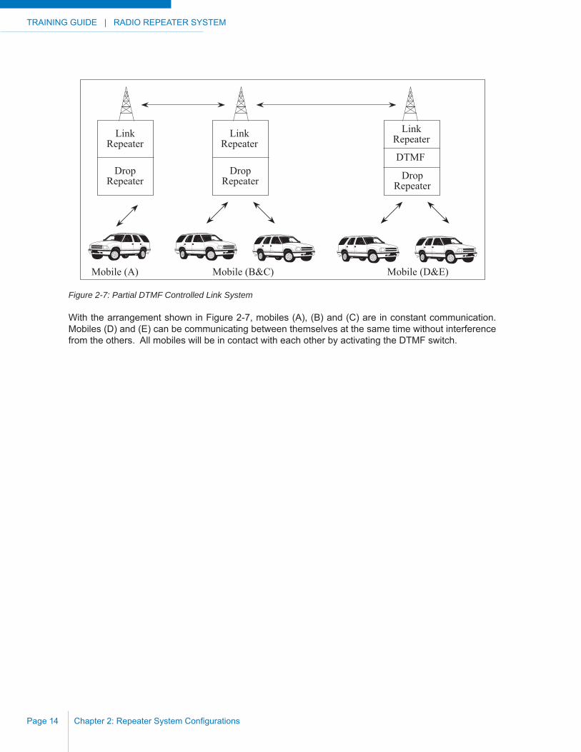
With the arrangement shown in Figure 2-7, mobiles (A), (B) and (C) are in constant communication. Mobiles (D) and (E) can be communicating between themselves at the same time without interference from the others. All mobiles will be in contact with each other by activating the DTMF switch.
Mobile (A) Mobile (B&C) Mobile (D&E)
LinkRepeater
DropRepeater
LinkRepeater
DTMF
DropRepeater
LinkRepeater
DropRepeater

RADIO REPEATER SYSTEM | TRAINING GUIDE
Chapter 2: Repeater System Confi gurations Page 15
CTCSS
Where frequencies are congested, the authorities may require frequency sharing, in which case it will be necessary to use some type of CTCSS (Continuous Tone Coded Squelch System) as shown in Figure 2-8. In such a system all mobiles, portables and base stations are provided with a sub-audible tone-encoder on the repeater channels. Each repeater uses a tone-decoder. These units are operating continuously when your microphone transmit button is depressed. Another signal on the same VHF or UHF frequency cannot activate the receiver at the repeater because it would be allocated a different CTCSS tone. This gives the appearance of a quiet channel all of the time although there can still be interference between users if both come on channel through their own systems at the same time.
Figure 2-8: CTCSS Protected Repeater Systems
OTHER CONFIGURATIONS
Another confi guration option for radio systems is telephone interconnects. Interconnects are usually electrically located between the base station and the telephone company lines. They enable mobiles to receive and initiate normal telephone calls.
Most authorities require that they be compatible with the telephone system, cause no electrical interference, and be controlled by the mobile, not the telephone caller. From a repeater users’ point of view, the most important requirement is that an interconnect has timing devices that enable its use and control through one or more repeaters.
The ultimate test of which interconnect to purchase is whether it will work on your repeater system. By entering the proper sequence of DTMF tones, the mobile user is able to dial either pre-programmed telephone numbers or any other telephone number. Limitations on length of call, restrictions on use of long distance numbers and other features may be programmed into the interconnect unit.
Mobiles A Mobiles B
Repeater A Repeater B
Tx-F1Rx-F2
CTCSSTone A
Tx-F1Rx-F2
CTCSSTone B
Possible Interference
Tx-F2Rx-F1
Tx-F2Rx-F1

TRAINING GUIDE | RADIO REPEATER SYSTEM
Chapter 2: Repeater System Confi gurationsPage 16
This Page Intentionally Left Blank
RADIO REPEATER SYSTEM | TRAINING GUIDE
Chapter 3: Repeater System Equipment Page 17
CHAPTER 3: REPEATER SYSTEM EQUIPMENT
When determining your system components remember that RELIABILITY is the most important consideration. Quality equipment is worth the extra cost, particularly in the long term.
You must also remember that changing a component in one part of the system may affect the other parts. For example, replacing the antenna type at one end of your linking path may require a change in antenna at the other end, and a change in antenna mounting and / or housing may affect .... In other words, there is great inter-dependence among the components. Remember also, when purchasing equipment, to compare the range of temperature that is expected at the site(s) to the component specifi cations supplied by the manufacturer.
In this section we are going to examine the individual pieces of equipment that make up the system.
REPEATER / BASE STATION
A repeater simply repeats everything that it hears. Any signal that is heard by the repeater’s receiver is transmitted by the attached transmitter. A Base Station simply passes on received signals to a console and the transmitter transmits audio from a console.
Repeaters can be assembled out of almost any combination of receivers and transmitters but in the context of low power, high performance repeaters, some of the details take on a special signifi cance. When a unit is powered by batteries, low current circuitry must be incorporated in the repeater to conserve battery life. Also, when a repeater is located on a snow covered mountain top, or in desert-like terrain, extreme temperature performance is important. A well designed grounding system is also important since the radio equipment is exposed to lightning to a far greater extent when placed on mountain tops. For greater coverage the repeaters can be connected in chains, so the cumulative audio distortion must be low. Base stations are typically the center of a communications hub and need to be of extremely high reliability for safety and continuity concerns, especially for law enforcement, fi re departments and other public safety agencies.

TRAINING GUIDE | RADIO REPEATER SYSTEM
Chapter 3: Repeater System EquipmentPage 18
Codan Radio Communications is a manufacturer of high reliabiltity repeaters and base stations. Codan receivers and transmitters frequency stability is specifi ed as +/- 1 ppm over the temperature range of -40 °C to +60 °C (-40 °F to +140 °F), a very wide range and very cold at the lower end. Low audio distortion in the receivers and transmitters (typically less than 2%) allows the the system designer to link several sites in a chain to provide extended coverage. Very low current draw on both the synthesized and crystal controlled repeaters and base stations allows these units to run from solar powered battery sites. Codan manufactures the repeaters and base stations in a modular confi guration, for ease of troubleshooting and maintenance.
a) Receiver modules
The receiver squelch circuit also has a form of hysteresis that allows the squelch control to be set at a level which eliminates noisy signals, but when a signal does open the squelch, the receiver goes to full sensitivity to allow a fading signal to come through and not be chopped up by the squelch snapping shut for each momentary fade.
As well as hysteresis squelch, the receiver response time can be modifi ed to suit particular applications. Some applications require a very fast response to an incoming signal, such as when several repeaters are linked into a chain. If each receiver was slow in turning on its attached transmitter, the delay over the length of the chain would be intolerable. The opposite situation is where it is desirable to hold the transmitter on the air for a brief period although there is no incoming signal. This arrangement allows two stations to talk back and forth without the repeater dropping out between transmissions.
b) Transmitter modules
The transmitter modules are of an adjustable output power, typically 0.5 to 8 Watts at VHF and UHF. The transmitters are rated at 100% duty cycle, meaning continuous operation at full output without degradation over the full temperature range.
An adjustable time-out-timer built into the transmitters can shut down the transmitter after a preset length of time (adjustable from 1 second to 8 hours). This will stop the transmitter from draining the batteries when a stuck microphone condition occurs.
RADIO REPEATER SYSTEM | TRAINING GUIDE
Chapter 3: Repeater System Equipment Page 19
c) System Regulator modules
The system regulator is a module that incorporates voltage regulators, an audio output stage, and a means of metering various stages of the receivers and transmitters mounted in the same subrack.
One special feature of the voltage regulation stage is an anti-latchup hysteresis circuit. This is a switch that turns off at a selected voltage and turns on at a different voltage. This feature is particularly useful when the repeater is powered by solar cells. In a standard installation, if the solar array does not recharge the battery fast enough (not enough sunlight), the repeater will discharge the battery completely and the repeater will stop operating. When the solar cells get some illumination they will start to charge the batteries and the repeater will come back to life for a short time, at least until the battery’s output voltage falls below the repeater’s operating point. With the hysteresis switch, the repeater is disconnected from the batteries when their voltage falls below approximately 8 volts, and it remains disconnected until the solar array has had a chance to charge the battery up to some higher voltage, usually around 11 volts. This differential arrangement prevents the repeater from turning on and off the air by allowing the power supply to receive a signifi cant charge before having to power the equipment. These hysteresis voltages can be changed if different voltage levels are required for turn-on and turn-off. (eg. 10 volts turn-off, 11.5 volts turn-on).
d) Control Cards
Each system may have an audio control card that routes audio, muting and COR-PTT signals, or a serial data control card that routes LVDS serial data and analog / digital COR-PTT signals. Each control card is set up for the specifi c confi guration of the repeater / base station. Setting up the control card with the specifi c confi gurations allows the transmitter and receiver modules to be swapped out and replaced with other receiver / transmitter modules for maintenance and troubleshooting procedures, without affecting the operation of the system.
e) Equipment Isolation
An important feature to consider is equipment isolation. By this we mean the amount of coupling between the transmitter and receiver other than through the antenna and associated duplexers / multicouplers. The amount of coupling between receiver and transmitter is highly variable and often causes problems which only show up after the installation is complete. The low-power repeaters are compact, and it is possible to arrange 2 receivers, 2 transmitters, a system regulator and the required control cards side by side in a 19 inch rack. This close physical spacing between the various components can create problems and so close attention must be paid to unit shielding. Each of the components (receiver, transmitter, system regulator, etc.) is mounted in an extruded aluminum enclosure which provides a continuous Radio Frequency Interference (RFI) tight seal. All leads entering these enclosures are fi ltered to prevent RFI from either entering or leaving on an unintended path. Double shielded co-axial cable between receivers, transmitters and duplexers is often used to enhance the isolation. With careful selection of a duplexer it is possible to operate a transmitter / receiver pair at a frequency spacing of less than 400 kHz, although this is not recommended.
TRAINING GUIDE | RADIO REPEATER SYSTEM
Chapter 3: Repeater System EquipmentPage 20
ANTENNAS
Antennas are manufactured to operate on a specifi c frequency and should not be altered in any way. There are fi ve factors of practical importance in the design of an antenna. These are antenna gain, bandwidth, impedance, physical size / construction, and radiation pattern. Any antenna that you purchase for use on a repeater system will have a nominal impedance of 50 ohms.
The gain, shown in dB on the manufacturer’s data sheet, is determined by the construction. However, a gain in one direction is accompanied by a loss in another direction.
When surveying proposed paths, think about the antennas that you will be using and watch for surfaces on either side of the path that may refl ect minor antenna lobes (see patterns below). Watch for near-fi eld obstructions when determining antenna placement. Although you will be limited if using a fi berglass enclosure as to antenna location, try to get the lowest antenna as high as possible to reduce signal absorption by the ground.
Where climatic extremes are anticipated, heavy duty models may be necessary. In addition, antennas are manufactured for a rated wind velocity and also for a rated wind velocity with one-half inch of radial ice load. Ensure that your site conditions are within these limitations.
In the manufacturer’s data, the bandwidth will usually be noted as a percentage of the frequency range. When pairs of frequencies are used for receiving and transmitting on the same antenna, as is nearly always the case in a repeater system, the bandwidth of the common antenna must be wide enough to include these frequencies. For example, if your operating frequencies on VHF are Tx 160 MHz, Rx 165 MHz and the antenna frequency range is 157-174 MHz, the bandwidth would have to be 165-160/174-157 x 100 or 5/17 x 100 = 29.4%. Bandwidth may also be shown as the voltage standing wave ratio (VSWR) over the frequency range. A VSWR of 1.5:1.0 or less over the frequency range is adequate for our purposes. Do not confuse bandwidth with beam width which is noted in degrees and is shown as the 0.707 voltage or half power point on the antenna pattern. This fi gure will probably be required when licensing your system.
RADIO REPEATER SYSTEM | TRAINING GUIDE
Chapter 3: Repeater System Equipment Page 21
The physical size and construction of the antennas becomes important when you consider the type of housing and antenna mounting that you will require for your repeater, which in turn is determined by the weather conditions at your chosen site and the amount of antenna gain your calculations show that you will require.
Note that your system also includes mobiles and portables, for which the most common antennas are the “whip” and “rubber-ducky” respectively. Remember that these antennas are also manufactured for use on a specifi c frequency or a narrow band of frequencies. These antennas are a compromise and provide little or no gain to the signal from the transmitter. Depending on the degree of compromise, they may even show a loss.
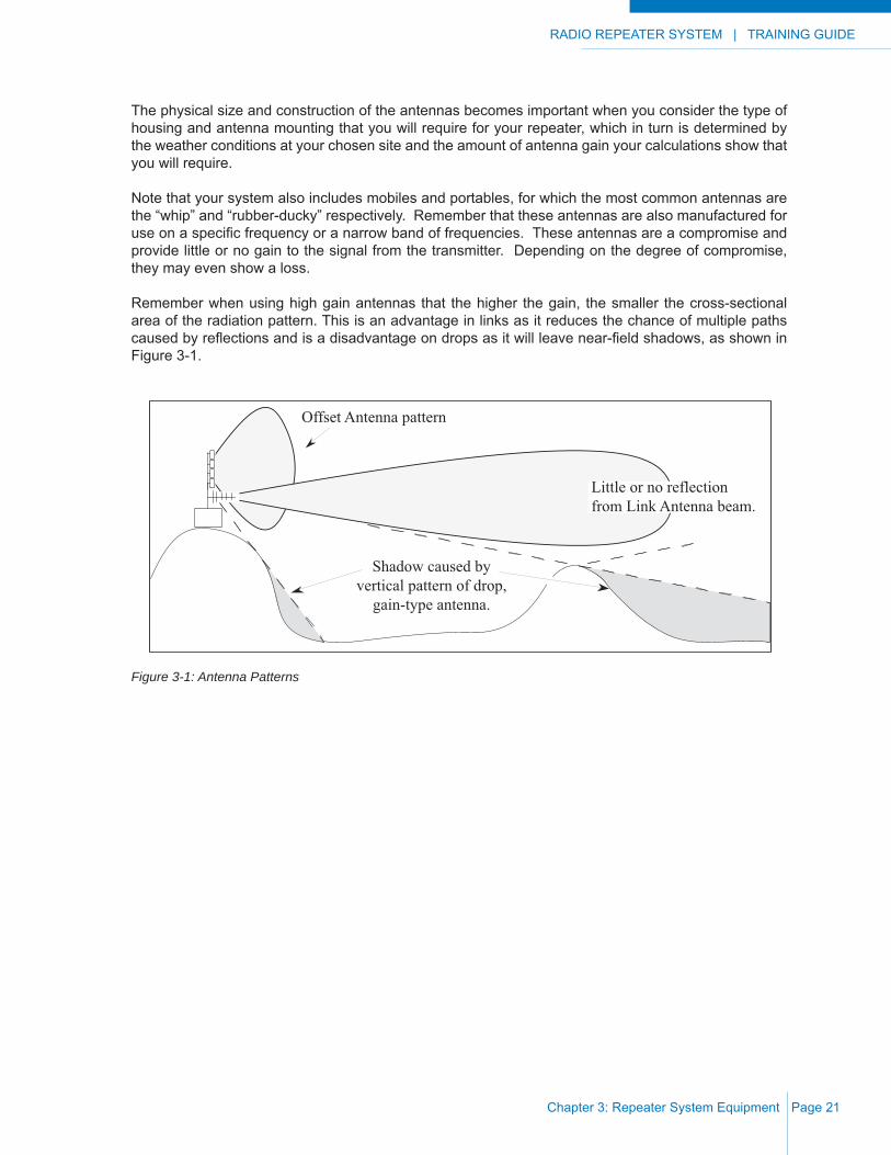
Remember when using high gain antennas that the higher the gain, the smaller the cross-sectional area of the radiation pattern. This is an advantage in links as it reduces the chance of multiple paths caused by refl ections and is a disadvantage on drops as it will leave near-fi eld shadows, as shown in Figure 3-1.
Figure 3-1: Antenna Patterns
Offset Antenna pattern
Shadow caused byvertical pattern of drop,
gain-type antenna.
Little or no reflectionfrom Link Antenna beam.

TRAINING GUIDE | RADIO REPEATER SYSTEM
Chapter 3: Repeater System EquipmentPage 22
The antennas in Figure 3-2 are “phased dipole arrays” and will provide increased gain in an omni-directional or offset pattern. They are usually used for local coverage or “drop” purposes.
Figure 3-2: Phased Dipole Array Antennas
dB RE l /2 DIPOLE 0 -10 -5 0 5 10-10-5510
+10°
0
-10°
+10°
0
-10°
-10 -5 0 5 10-10-50510dB RE l /2 DIPOLE
-10 -5 0 5 10-10-50510
Azimuth pattern - OMNI
+10°
0
-10°
+10°
0
-10°
-10 -5 0 5 10-10-50510dB RE l /2 DIPOLE
Vertical pattern - OMNI
FOUR BAY 150 MHz OMNIdipole array with typicalazimuth and vertical radiationpatterns shown directly below
FOUR BAY 150 MHz OFFSETdipole array with typical azimuthand vertical radiation patternsshown directly below
Vertical pattern - OFFSET
Azimuth pattern - OFFSET
dB RE l /2 DIPOLE

RADIO REPEATER SYSTEM | TRAINING GUIDE
Chapter 3: Repeater System Equipment Page 23
The antenna in Figure 3-3 is a “beam” or “yagi” and is usually used for linking purposes. You may see it polarized in a horizontal or vertical position. A VHF yagi will be larger than a UHF yagi. A yagi provides increased gain in one direction. A typical pattern is also illustrated.
Figure 3-3: Yagi Antenna
Another type used on links where a higher front-to-back ratio is required is the corner refl ector antenna shown in Figure 3-4.
Figure 3-4: Corner Refl ector Antenna
Examples of antenna data and radiation patterns can be found in Appendix F.
Typical Horizontal RadiationPattern For Vertical Polarization
BEAM ANTENNA
+10°
0
-10°
DIPOLEREFERENCE
dB RE l /2 DIPOLE-10 -5 0 5 10-10-50510
Typical Horizontal RadiationPattern.
+10°
0
-10°
CORNER REFLECTOR
DIPOLEREFERENCE
dB RE l /2 DIPOLE-10 -5 0 5 10-10-50510

TRAINING GUIDE | RADIO REPEATER SYSTEM
Chapter 3: Repeater System EquipmentPage 24
DUPLEXERS, MULTICOUPLERS AND COMBINERS
Band-pass and band-reject duplexers allow use of the same antenna for transmitting and receiving. Multicouplers and combiners are an arrangement of band-pass and band-reject cavities which permit use of the same antenna by a number of receivers and transmitters respectively. Additional duplexers can be required in such a system.
Duplexers, multicouplers and combiners have the following characteristics which are important to your system design:
a) the unit(s) must match the frequency range, temperature range, impedance, and termination type (coaxial fi ttings) of the rest of your equipment;
b) the manufacturer’s data sheet fi gures noting frequency separation and isolation must match your requirement. For example, if your frequency separation is 5 MHz, there is no need to purchase a duplexer that has a minimum frequency separation of 0.8 MHz. On the other hand, conditions at your site (frequencies used by others) may require better than the usual 50 to 90 dB isolation;
c) ensure that the power output of the transmitters / power amplifi ers does not exceed the specifi ed power rating of the unit. The VSWR should be as low as possible, but this item is controlled by the construction of the unit and is nearly always less than 1.5:1.0;
d) insertion loss must be noted for your later calculation of signal levels, and;
e) the mechanical specifi cation of the unit by the manufacturer must be noted to ensure space in your enclosure. As a rule of thumb, the less the minimum frequency separation and the higher the isolation, the larger and heavier the unit.

RADIO REPEATER SYSTEM | TRAINING GUIDE
Chapter 3: Repeater System Equipment Page 25
POWER SUPPLIES
a) AC PowerThe low powered repeaters discussed are basically 12 volt units. Converters are available from various manufacturers or from the repeater supplier. Depending on the reliability of AC power to your proposed mountain-top site, use of the above is one alternative. Another suggestion when AC is available, is to run the repeater equipment from its usual battery supply (to be discussed in the next sections) with an AC operated battery charger attached. If power fails, your repeater will continue to operate up to the number of hours to which the battery supply is designed; and on resumption of power, the batteries will be recharged.
b) Transmit Duty CycleBefore discussing batteries, let’s fi rst think about how much our repeater system will be used. Many radio systems are inactive more than active; in fact, a usage or transmit duty cycle of 3 or 4% is quite often the case. There are 8,760 hours or 525,600 minutes in a year. If your business is conducted during daylight or normal working hours, you would use your system possibly for 8 or 9 of each 24 hours. During that time you may make only a dozen or so calls. Most radio calls will be short, a maximum of three minutes. Although your repeater receivers will be operating all of the time, the repeaters will only be transmitting, in the above case, for 36 minutes per day, or 13,140 minutes per year. This works out to a duty cycle of 2 1/2%. Even a very busy system with 20 one-minute calls per hour for 16 hours totals only 22%. In 90% of cases an 8% transmit duty cycle will be more than adequate. If your system is likely to be used more at one time of the year than another, you may wish to increase this slightly.
c) BatteriesA reliable rechargeable battery is the nickel-cadmium (Ni-Cad) cell. Ni-Cad cells (used to make up the battery of your voltage requirement) have low internal resistance, and are capable of high peak loads over the temperature range -40 °C to +50 °C (-40 °F to +122 °F). They have excellent performance when cycled, are self regulating, and are undamaged by short circuits and polarity reversals. The gasses that are produced by Ni-Cads are neither toxic nor corrosive, and they have an exceptionally long life. Ni-Cads come in 1.5 Volt cells and are approximately 69 mm X 134 mm X 394 mm (2.75” X 5.25” X 15.5”) and weigh 6.8 kg (15 lbs.).

TRAINING GUIDE | RADIO REPEATER SYSTEM
Chapter 3: Repeater System EquipmentPage 26
d) Solar PowerYou will fi nd some level of government or agricultural or environmental bureaucracy will be able to supply you with solar insolation (the number of bright sunshine hours (BSH) per year) and average annual temperature at some data point near your proposed site. If this data point is, for example, in a fog shrouded valley, or your proposed site is on a mountain-top which is often obscured by cloud, adjustments (of perhaps +/- 10%) will have to be made to the available fi gures.
Enter site name, data point, BSH and any adjustments on the Solar Sizing Worksheet (a completed worksheet is shown on the next page). Calculate the peak hours of sunshine per day as shown. We have used 1927 average yearly bright sunshine hours at a data point called “Lytton”, about 56 km (35 miles) from our proposed BRIDGE ARS. Our example shows an adjustment of +5% for our site, as the data point, being in a deep valley, is likely to be in shadow earlier in the day than the repeater site. The next fi gure that you will require for your calculations will be the average annual temperature at the data point, use our example, 9 °C (48 °F). Our site is at 1372 meters (4500 ft.) and the data point is at 281 meters (922 ft.), a difference of 1091 meters (3578 ft.). The normal adiabatic lapse rate (change in temperature with elevation) is -0.5 °C per 100 meters. Therefore, our adjusted temperature will be 9 - (1091/100) x 0.5 = 3.5 °C. Percent duty cycle, as calculated in part b) above, is entered as 0.08 based on our 9 operating hours per day. Calculation of current (I) used is taken directly from the repeater manufacturer’s technical specifi cations. Our fi gures for standby are 24 (hours) x .036 A for VHF and .048 A times 24 for UHF, totaling 2.0 Ah. Total transmitter current for our site is 1.2 A x 9 (hours) x 0.08 (duty cycle) for VHF and 1.0 A x 9 x 0.08 for UHF, totaling 1.6 Ah. The total (receiver and transmitter) daily requirement is entered as 3.6 Ah. Enter the repeater operating voltage, the battery type, volts per cell and number of cells required (in series), and calculate the days of storage. One month is adequate for this fi gure, as you are assuming that there will be no sunlight for recharging in this period. However, you may want to double the battery size to accomodate for variables. From the battery manufacturer’s technical specifi cations, fi nd the fl oat voltage fi gure and enter it on the sheet.
Some solar panels already have an internal reverse current diode installed. If not, one will be necessary and a fi gure of 0.65 volts should be entered as a loss. If heavy duty Ni-Cad cells are used, a regulator is not required, although a simple zener diode bypass regulator may give peace of mind if you are worried about overheating. If another type of battery is used, you may have to include a regulator, with its attendant voltage loss, in the power supply design. When the maximum charging current of the module is less than approximately 2% of the battery capacity (e.g. panel producing 1.4 A and a battery of 100 Ah capacity or more) a regulator is not required. Enter the panel manufacturer’s name and panel model number (just for reference later), the nominal panel voltage (from the manufacturer’s data), and calculate the panel current as shown. Calculate the module current output per day by multiplying the average peak hours of sunshine per day by the panel current (using the manufacturer’s power graph). The total daily power requirement divided by the module current will then give you the number of panels required. Our example shows 0.5 or one panel required. We could re-calculate for a lower output panel if desired or re-calculate to see how high a duty cycle one panel will permit (in our example, this works out to 33%).
With advances in design, the mounting angle is not as critical as it was previously. A useful rule of thumb is to mount your panel at an angle to earth equivalent to your latitude plus fi ve degrees. Remember to point the panel(s) true south, towards the sun at noon (this is true for most sites in Canada and the United States but is dependant on your geographical location). Different types of panels require different mounting techniques. Follow the manufacturer’s recommendations. One panel available that has proven useful is built on a fl exible thin sheet, thus mounting on a curved surface (see the following section on accommodations) is possible.

RADIO REPEATER SYSTEM | TRAINING GUIDE
Chapter 3: Repeater System Equipment Page 27
SOLAR SIZ ING WORKSHEETSITE NAME BRIDGE ARS DATA POINT LYTTON
AVERAGE YEARLY BRIGHT SUNSHINE HOURS (BSH) 1927
ADJUSTED (+ or - a +5 percent) TOTAL BSH 2023
AVERAGE PEAK HOURS PER DAY (total BSH x 0.0017) = B = 3.44
AVERAGE ANNUAL TEMPERATURE (at monitor point) c = +9
ADJUSTED FOR SITE (c - adiabatic lapse rate) +20 = C = 23.5
DUTY CYCLE (shown as a decimal, eg. 8% = .08) = dc = 0.08
TOTAL DAILY NORMAL OPERATING HOURS a = 9 h
TOTAL STANDBY CURRENT (24 x Rx(I)) = b = 2.0 Ah
TOTAL TX CURRENT (a x Tx(I) x dc) = c = 1.6 Ah
TOTAL DAILY REQUIREMENT (b + c) = r = 3.6 Ah
REPEATER OPERATING VOLTAGE V = 12.5 Volts
BATTERY TYPE Ni-Cad VOLTS PER CELL v = 1.2 Volts
NUMBER OF CELLS REQUIRED IN SERIES (V/v) = VI = 10 cells
ONE BANK OF CELLS WILL GIVE (100 / r) 28 DAYS OF STORAGE
CHARGE VOLTAGE PER CELL CV = 1.4 Volts
REVERSE CURRENT DIODE OR REGULATOR LOSS D = 0 Volts
NOMINAL PANEL VOLTAGE (from manufacturers data) = m = 14 Volts
PANEL O/P VOLT REQ’D (D+R+(VIxCV)+(0.004(C x m))) = L = 15.8 Volts
PANEL CURRENT (from man. power graph) at L volts = M = 1.9 A
MODULE CURRENT PER DAY (B x M) = M1 = 6.5 A
NUMBER OF PANELS REQUIRED = (r / M1) = 0.5 modules
TRAINING GUIDE | RADIO REPEATER SYSTEM
Chapter 3: Repeater System EquipmentPage 28
ACCOMMODATION
Before discussing buildings and antenna mounts, it should be noted that the repeater and duplexer(s) are often mounted in an enclosed water and dust resistant housing on a standard rack. When calculating rack space requirements, note that one standard rack space equals 4.44 cm (1 3/4 inches). In the interest of neatness and ease of maintenance, shelves of one type or another should also be constructed for your batteries.
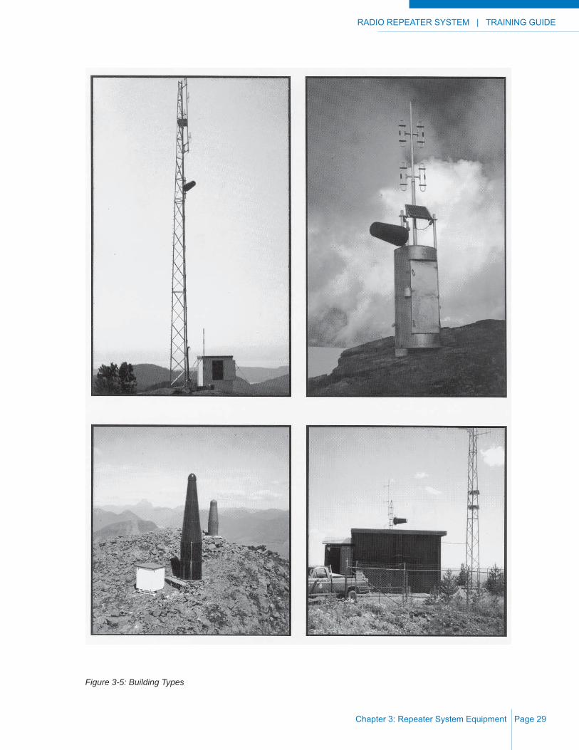
Buildings of all types from plywood and pre-fab units through brick, concrete and metal, to those constructed from fi berglass have been used to house repeaters. Your choice depends on weather conditions at your proposed site and the space required. Repeater systems in areas where high winds, heavy snow levels and / or heavy icing is prevalent are the most diffi cult to house. Consider the following:
i) square buildings ice up easily at the corners, and may be diffi cult to fi nd in deep snow;
ii) in deep snow, cylindrical buildings have proved most satisfactory as wind action “scours out” the snow around the circumference;
iii) expect condensation in metal buildings in most high locations;
iv) treated wooden poles are superior to light metal towers up to 15 meters (50 ft.) in height. Allow 0.3 meters (1 foot) in the ground for each 3 meters (10 feet) above ground. Do not concrete a pole into the ground;
v) marmots, porcupines and wolverine will nest in your building if they can enter. In areas where they are known, use construction material other than wood;
vi) vandals have been known to winch down fences and gates, power saw through walls and shoot off locks. Concrete construction and steel doors may deter them;
vii) the building must be large enough to hold the equipment and usually the power supply. It is also an advantage if the antennas can be inside, as under these conditions, light duty (and less expensive) antennas can be used. In this case, high winds and icing are no longer a factor;
viii) outside antennas and solar panel mounts must be robust enough to withstand high winds and icing conditions whether mounted on a pole or a heavy duty tower;
ix) ideally the building door is situated to the south (to allow natural light inside), away from the prevailing winds (where ice and snow will congregate and require more effort to clear for maintenance) and visible from road, trail or helicopter landing (for safety and ease of access), and;
x) when your site is below timber line, unless on a bald knob with a “good take-off” in all directions, a tower, high enough so that the antennas will be in the clear, will probably be required. A self-supporting tower is recommended. The accommodation for your equipment and batteries can then be of any convenient type.
Figure 3-5 shows different building types under varying conditions. Particularly note the cylindrical fi berglass housing.
RADIO REPEATER SYSTEM | TRAINING GUIDE
Chapter 3: Repeater System Equipment Page 29
Figure 3-5: Building Types
TRAINING GUIDE | RADIO REPEATER SYSTEM
Chapter 3: Repeater System EquipmentPage 30
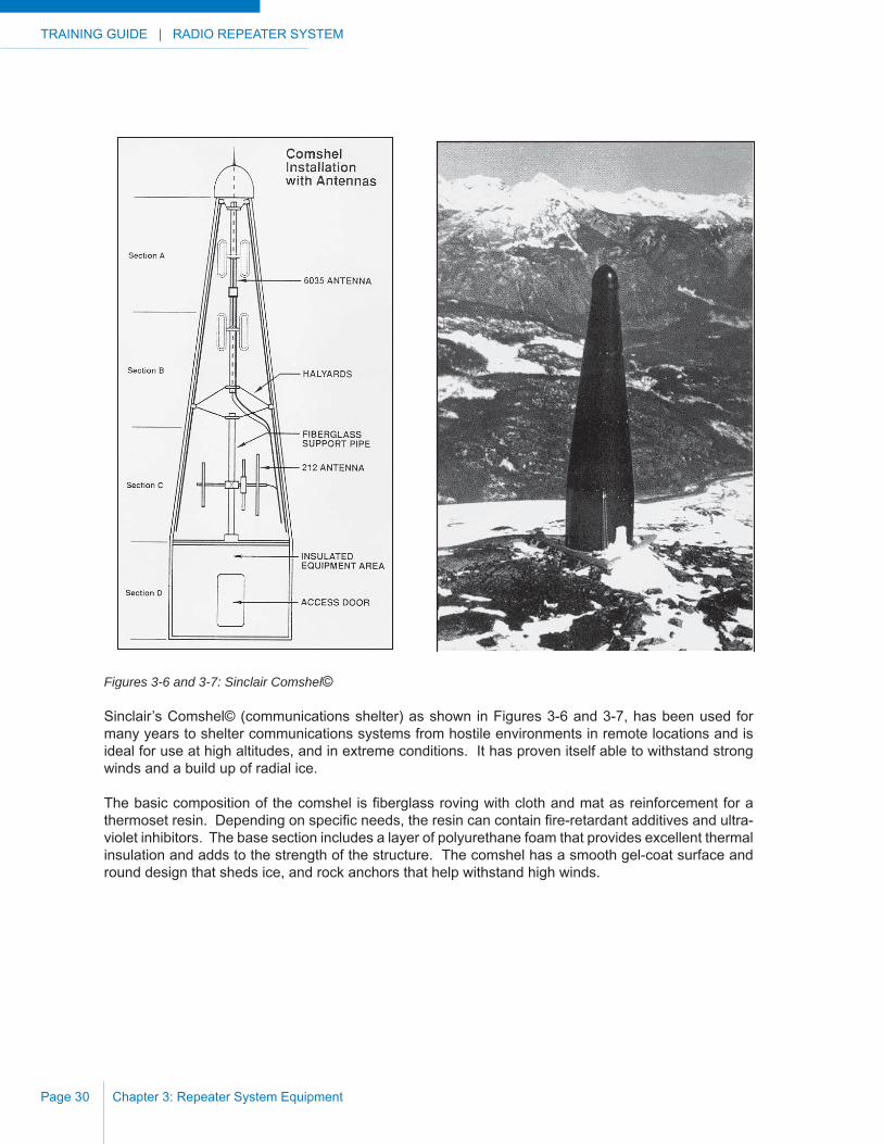
Figures 3-6 and 3-7: Sinclair Comshel©
Sinclair’s Comshel© (communications shelter) as shown in Figures 3-6 and 3-7, has been used for many years to shelter communications systems from hostile environments in remote locations and is ideal for use at high altitudes, and in extreme conditions. It has proven itself able to withstand strong winds and a build up of radial ice.
The basic composition of the comshel is fi berglass roving with cloth and mat as reinforcement for a thermoset resin. Depending on specifi c needs, the resin can contain fi re-retardant additives and ultra-violet inhibitors. The base section includes a layer of polyurethane foam that provides excellent thermal insulation and adds to the strength of the structure. The comshel has a smooth gel-coat surface and round design that sheds ice, and rock anchors that help withstand high winds.
RADIO REPEATER SYSTEM | TRAINING GUIDE
Chapter 4: Installation and Maintenance Page 31
CHAPTER 4: INSTALLATION AND MAINTENANCE
INSTALLATION HINTS AND TECHNIQUES
Similar to installation of a mobile or a base station, the installation of a repeater requires care and neatness. The following suggestions may be of value:
a) All outside cabling should be well secured.
b) Any messenger cable between poles, towers and buildings should be of good quality 6 mm (1/4 in) galvanized wire, or 3 mm (1/8 in) stainless wire.
c) Ground lines of 6 mm (1/4 in) copper wire from antennas must take the shortest path to earth. Weld or double clamp connections. Ensure that the ground lines and the coaxial cables are separated by as much distance as possible.
d) Secure coaxial cables using ultra-violet light resistant plastic ties (the black ones). Coaxial cable entry to buildings through lightning resistant feed-throughs is recommended.
e) Crimp-on, Type N, coaxial cable connectors are also recommended.
f) If using a cylindrical fi berglass building for accommodation, ensure that curved battery shelves are secured to the base. High winds on site can move a shelf right across the fl oor, even when loaded with 450 kg of batteries.
g) If using a fi berglass building, use 1.8 m (6 feet) rock bolts to anchor the corners instead of tying down with cables and short rock anchors.
TRAINING GUIDE | RADIO REPEATER SYSTEM
Chapter 4: Installation and MaintenancePage 32
h) Mark antenna directions on the inside of buildings so that in the event the antennas are inadvertently moved they can be returned to the correct azimuth.
i) The repeater station, when complete, should have a record of equipment (on site) and measured signal levels so that future maintenance technicians will have a standard for reference. A second copy should be kept on fi le at a different location for convenient reference. A repeater site data form is shown in Appendix I.
j) Grounds must go directly to ground. In addition, all coaxial cables and drip loops at cable entrances to the building should not have sharp bends.
k) Guy wires are not recommended. However, if they are used, fl ag them well for better visibility.
l) Vapor corrosion inhibitors placed inside the enclosure are recommended.
MAINTENANCE
With the purchase of good, reliable equipment, maintenance can be held to a minimum. In fact, most large scale users of mountain-top equipment “service to failure”, rather than having a maintenance schedule.
Most outages will be caused by catastrophic failure owing to lightning strikes or other weather damage, by power supply failures, or by interference from others. It is not unknown for a repeater to run for fi ve to ten years with no attention at all, until the battery supply has to be replaced. However, because these units are usually in fairly inaccessible locations, it is recommended that for every three repeater units (VHF or UHF), another repeater unit be held as a spare. With a system of two or more repeaters, if there is an outage, it is fairly simple to logically determine which transmitter or which receiver is out at which location. When the repeater itself is the culprit, it is usually not economical to repair it on site. Having a spare transmitter, repeater and control card carried by the maintenance technician (set up on the correct frequencies) is much simpler than trying to repair equipment on site.
When on site, however, every effort should be made to bring all equipment up to the original recorded values by checking transmitter power output and deviation, VSWR of the antenna system(s), duplexer losses, receiver and transmitter frequencies and receiver sensitivity. Visual inspection of all components on the site should also be conducted. Ensure that all connectors and clamps are tight and free from corrosion. Keep the records up to date. Make sure everything is clean and tidy, and before leaving the site, confi rm that the system operates correctly.

RADIO REPEATER SYSTEM | TRAINING GUIDE
Chapter 4: Installation and Maintenance Page 33
LIGHTNING PROTECTION
There is no guaranteed method of eliminating damage due to lightning, but there are ways to minimize the damage received from the result of a direct hit and to practically eliminate damage from all but the most severe indirect strikes. The accepted method to suppress damage from lightning strikes is to provide an easy path or multiple paths for these strikes in their travel to ground. The less the resistance of the path to ground, the sooner the charge can be “bled off”, preferably before the charge can build to the point where damage is caused.
The behavior of a current surge is infl uenced by other variables (normally undesirable ones such as inductance, resistance and capacitance) which can, in this case, assist in reducing destruction. Bends in coaxial cables, twisted together power cabling, and feed-through lightning arrestors are examples.
There are at least two schools of thought concerning grounding of equipment. One is that everything should be attached to everything else and then grounded through a large diameter copper wire or bar. Another is to provide a “cone of protection” by installing a rod or wire at the highest point of your installation with #4 or larger copper wire running directly to ground. By minimizing resistance between a structure and ground, we can minimize damage to equipment within a hypothetical logarithmic cone, where the top of the cone is the highest point which is directly connected to the ground and the radius of the base of the cone is the same as the distance from the top of the cone to ground. Inside antennas and repeater equipment are left to fl oat within the resulting “cone of protection”. Outside antennas would be connected to the main ground as it drops down the tower or pole. Any wire connections, copper to copper, should be made by welding or double clamping. Non-similar metals will have to be clamped and checked every few years for cleanliness of the joint and for tightness. Non-corrosive, conducting compounds are available for this purpose.
When using a fi berglass shelter, the steel spider should be connected to the main ground. Ensure that the coaxial cables are as far as possible from the ground wire. Soil resistivity increases with decreases in temperature, therefore, ensure that your ground rod(s) is long enough to penetrate below the frost level. Radials, equal to the height of the structure and connected to the main ground, will increase your protection as will a surrounding ring of buried copper wire connected to these radials using ground rods at each connecting point. Such a circle and radials provide protection from “ground bumps” (charges conducted through the ground from nearby lightning hits). When using ground rods drilled into rock, use a conductive grout. Use two ground rods at a tower or pole base, 180 degrees apart. Do not install the ground rods within a concrete tower base - they have been known to blow it apart.
TRAINING GUIDE | RADIO REPEATER SYSTEM
Chapter 4: Installation and MaintenancePage 34
INTERFERENCE
Interference occurs when undesired signals prevent the reception of wanted signals. It can be caused by either internal or external sources. The use of poorly adjusted transmitters or receivers are one example of on-site noise or interference. Sparking electrical sources such as power drills and miscellaneous co-located microprocessor telemetry equipment are other examples. In addition, random noise from electrical and heavy snow or sleet storms may cause interference on your system. Transmitter noise from other transmitters, not necessarily nearby, can cause interference that is particularly diffi cult to solve. Nulling out interfering signals with antenna patterns is one effective method of reducing or removing this problem.
By far the most common interference problem is inter-modulation interference (commonly called “intermod”). It is the product of two or more signals beating together to produce interfering signals to your receive frequency. One of your own on-site transmitters may be part of the problem, beating with some other unknown signal.
A complete listing of all transmitter and receiver frequencies and their users, including your own, within a reasonable distance of the site (say two kilometers) is necessary to calculate the many combinations of intermod that can occur. There are computer programs available to calculate possible interfernce through intermod. The following example shows the necessary calculations for a three repeater (A, B and C) site:
One of A’s transmit frequencies is 138.615 MHz; one of B’s transmit frequencies is 138.885 MHz. C’s receive frequency is 138.375 MHz. Two times A’s frequency minus B’s frequency (or 2A-B) equals 30 kHz off C’s receive frequency (277.23 - 138.885 = 138.345). Depending on other variables such as distance between transmitters, distance between transmitters and receiver, antenna installations, etc,. this difference of 30 kHz may or may not cause an intermod interference to C’s receiver. This particular equation is fairly easy to solve as it means that the second harmonic of A’s frequency is the basic culprit. It may be that A’s transmitter is not correctly tuned, allowing the second harmonic to dominate, or it may require a fi lter be installed (on A’s transmitter) to trap out that second harmonic. The co-operation of all on-site users is required to eliminate intermod interference. If a site has been interference free and a new user causes problems, it is usually the new user who pays for the purchase of any necessary fi ltering.
In many cases, the licensing authorities will have done the initial work on this problem before allowing you to do your installations. Therefore, early in the project process, you should discuss with them your radio communications problems and proposed solutions. If you intend to use existing frequencies, it is in your own interests to have any intermod information available before starting your repeater system design.
RADIO REPEATER SYSTEM | TRAINING GUIDE
Appendix A: Drawing Coverage Maps Page 35
APPENDIX A: DRAWING COVERAGE MAPS
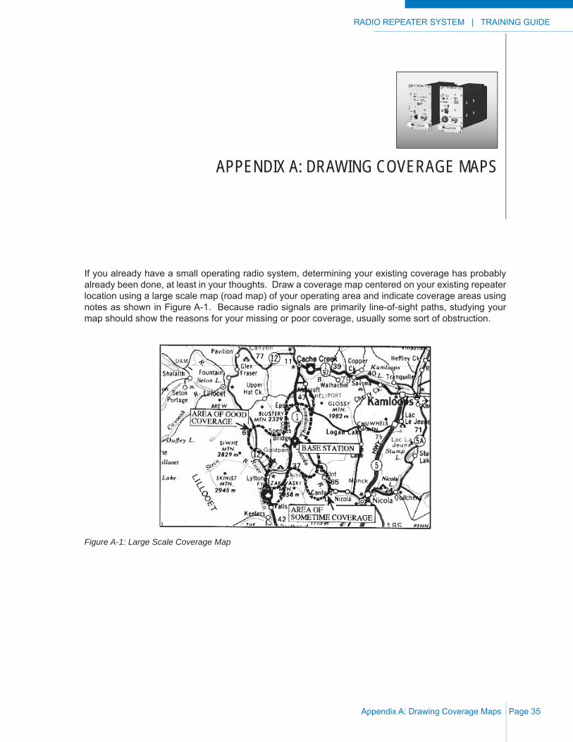
If you already have a small operating radio system, determining your existing coverage has probably already been done, at least in your thoughts. Draw a coverage map centered on your existing repeater location using a large scale map (road map) of your operating area and indicate coverage areas using notes as shown in Figure A-1. Because radio signals are primarily line-of-sight paths, studying your map should show the reasons for your missing or poor coverage, usually some sort of obstruction.
Figure A-1: Large Scale Coverage Map
TRAINING GUIDE | RADIO REPEATER SYSTEM
Appendix A: Drawing Coverage MapsPage 36
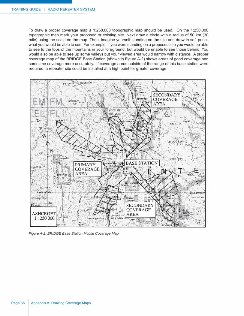
To draw a proper coverage map a 1:250,000 topographic map should be used. On the 1:250,000 topographic map mark your proposed or existing site. Next draw a circle with a radius of 50 km (30 mile) using the scale on the map. Then, imagine yourself standing on the site and draw in soft pencil what you would be able to see. For example, if you were standing on a proposed site you would be able to see to the tops of the mountains in your foreground, but would be unable to see those behind. You would also be able to see up some valleys but your viewed area would narrow with distance. A proper coverage map of the BRIDGE Base Station (shown in Figure A-2) shows areas of good coverage and sometime coverage more accurately. If coverage areas outside of the range of this base station were required, a repeater site could be installed at a high point for greater coverage.
Figure A-2: BRIDGE Base Station Mobile Coverage Map
RADIO REPEATER SYSTEM | TRAINING GUIDE
Appendix A: Drawing Coverage Maps Page 37
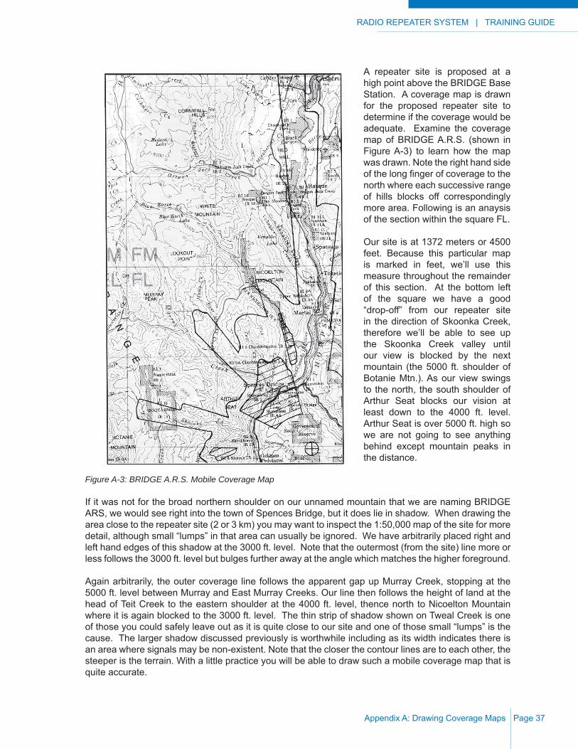
A repeater site is proposed at a high point above the BRIDGE Base Station. A coverage map is drawn for the proposed repeater site to determine if the coverage would be adequate. Examine the coverage map of BRIDGE A.R.S. (shown in Figure A-3) to learn how the map was drawn. Note the right hand side of the long fi nger of coverage to the north where each successive range of hills blocks off correspondingly more area. Following is an anaysis of the section within the square FL.
Our site is at 1372 meters or 4500 feet. Because this particular map is marked in feet, we’ll use this measure throughout the remainder of this section. At the bottom left of the square we have a good “drop-off” from our repeater site in the direction of Skoonka Creek, therefore we’ll be able to see up the Skoonka Creek valley until our view is blocked by the next mountain (the 5000 ft. shoulder of Botanie Mtn.). As our view swings to the north, the south shoulder of Arthur Seat blocks our vision at least down to the 4000 ft. level. Arthur Seat is over 5000 ft. high so we are not going to see anything behind except mountain peaks in the distance.
Figure A-3: BRIDGE A.R.S. Mobile Coverage Map
If it was not for the broad northern shoulder on our unnamed mountain that we are naming BRIDGE ARS, we would see right into the town of Spences Bridge, but it does lie in shadow. When drawing the area close to the repeater site (2 or 3 km) you may want to inspect the 1:50,000 map of the site for more detail, although small “lumps” in that area can usually be ignored. We have arbitrarily placed right and left hand edges of this shadow at the 3000 ft. level. Note that the outermost (from the site) line more or less follows the 3000 ft. level but bulges further away at the angle which matches the higher foreground.
Again arbitrarily, the outer coverage line follows the apparent gap up Murray Creek, stopping at the 5000 ft. level between Murray and East Murray Creeks. Our line then follows the height of land at the head of Teit Creek to the eastern shoulder at the 4000 ft. level, thence north to Nicoelton Mountain where it is again blocked to the 3000 ft. level. The thin strip of shadow shown on Tweal Creek is one of those you could safely leave out as it is quite close to our site and one of those small “lumps” is the cause. The larger shadow discussed previously is worthwhile including as its width indicates there is an area where signals may be non-existent. Note that the closer the contour lines are to each other, the steeper is the terrain. With a little practice you will be able to draw such a mobile coverage map that is quite accurate.

TRAINING GUIDE | RADIO REPEATER SYSTEM
Appendix A: Drawing Coverage MapsPage 38
Figure A-4 shows IRON MOUNTAIN A.R.S., another example of a mobile coverage map. This site could be linked to BRIDGE A.R.S. for even greater coverage of the radio system.
Figure A-4: IRON MOUNTAIN A.R.S. Mobile Coverage Map

RADIO REPEATER SYSTEM | TRAINING GUIDE
Appendix B: Drawing Path Profi les Page 39
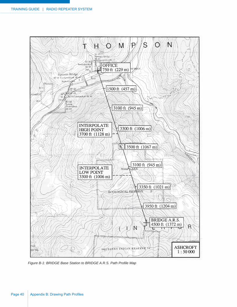
APPENDIX B: DRAWING PATH PROFILES
In Appendix A, coverage maps were drawn for the BRIDGE Base Station (Offi ce) and BRIDGE A.R.S. showing the expected coverage of those sites. To determine if the BRIDGE A.R.S. site will communicate with the Base Station a path profi le must be drawn. If any two sites (base station to repeater or repeater to repeater) are to be linked together, a path profi le between those two sites must be drawn.
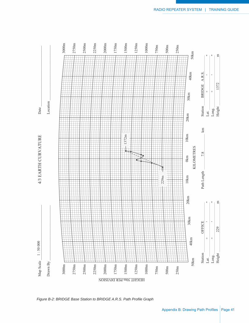
On a 1:50,000 map covering the area between the two sites, draw a straight line between the two points as shown in Figure B-1. Find the center and scale off from that point at 1 km intervals to each end. Prepare the 4/3 earth curvature profi le paper with names, date, and any other pertinent information as shown in Figures B-2 and B-3.
From the 1:50,000 map which you have marked and again starting at the center, working your way out to each end in turn, transfer the elevations from the map, one kilometer at a time. You may wish to interpolate highs and lows between points as shown on the map. Although the example shows the points marked in heights for each kilometer, you will fi nd that marking is unnecessary after you have done one or two profi les. You can now see whether or not the path is line-of-sight. Once the path profi le has been drawn, path calculations need to be made for path loss characteristics and signal levels.
TRAINING GUIDE | RADIO REPEATER SYSTEM
Appendix B: Drawing Path Profi lesPage 40
Figure B-1: BRIDGE Base Station to BRIDGE A.R.S. Path Profi le Map
RADIO REPEATER SYSTEM | TRAINING GUIDE
Appendix B: Drawing Path Profi les Page 41
250m
500m
750m
1000
m
1250
m
1500
m
1750
m
2000
m
2250
m
2500
m
2750
m
3000
m
250m
500m
750m
1000
m
1250
m
1500
m
1750
m
2000
m
2250
m
2500
m
2750
m
3000
m
HEIGHT 50m PER DIVISION
50km
40km
30km
20km
10km
0km
10km
20km
30km
40km
50km
4/3
EAR
TH C
UR
VA
TUR
EM
ap S
cale
___
____
____
____
____
____
____
___
Dra
wn
By
____
____
____
____
____
____
____
__
Dat
e __
____
____
____
____
____
____
____
___
Loca
tion
____
____
____
____
____
____
____
__
KIL
OM
ETR
ES
Stat
ion
OFF
ICE
Lat.
°
'
"
Long
.
°
'
"
Hei
ght
22
9
m
Stat
ion
BR
IDG
E A
.R.S
.La
t.
°
'
"Lo
ng.
°
'
"H
eigh
t
137
2
m
Path
Len
gth
7.
8
k
m
1 : 5
0 00
0
1372
m
229m
Figure B-2: BRIDGE Base Station to BRIDGE A.R.S. Path Profi le Graph

TRAINING GUIDE | RADIO REPEATER SYSTEM
Appendix B: Drawing Path Profi lesPage 42
Figure B-3: BRIDGE A.R.S. to IRON MOUNTAIN A.R.S. Path Profi le Graph
250m
500m
750m
1000
m
1250
m
1500
m
1750
m
2000
m
2250
m
2500
m
2750
m
3000
m
250m
500m
750m
1000
m
1250
m
1500
m
1750
m
2000
m
2250
m
2500
m
2750
m
3000
m
HEIGHT 50m PER DIVISION
50km
40km
30km
20km
10km
0km
10km
20km
30km
40km
50km
4/3
EAR
TH C
UR
VA
TUR
EM
ap S
cale
___
____
____
____
____
____
____
___
Dra
wn
By
____
____
____
____
____
____
____
__
Dat
e __
____
____
____
____
____
____
____
___
Loca
tion
____
____
____
____
____
____
____
__
KIL
OM
ETR
ES
Stat
ion
BR
IDG
E A
.R.S
.La
t.
°
'
"Lo
ng.
°
'
"H
eigh
t
1372
m
Stat
ion
IR
ON
MTN
A.R
.S.
Lat.
°
'
"
Long
.
°
'
"
Hei
ght
1
692
m
Path
Len
gth
5
2.2
km
1692
m
1372
m
1 : 5
0 00
0

RADIO REPEATER SYSTEM | TRAINING GUIDE
Appendix C: Calculating Path Loss Page 43
APPENDIX C: CALCULATING PATH LOSS
We see from the profi le of the path from BRIDGE ARS to BRIDGE Base Station (Offi ce) that it is not line-of-sight. The connecting line passes through a “lump” or obstruction. In most cases, if any paths that you draw (particularly long paths) are not line-of-sight, calculation of path loss becomes extremely complicated, and you are advised to seek professional help. Since this is a very short path we can make allowances. If the free space path loss for the distance is 105 dB or less, and there is an obstruction within 20% of the center of the path that does not exceed 150 m, the path will likely be quite safe for year round use. Under these conditions, when doing your path calculations, add 20 dB for shadow loss. Another example, directly related to our example is: If the free space path loss is 95 dB or less and the obstruction within 20% of the center of the path does not exceed 500 m, add 35 dB. It is always best under these circumstances to measure the path loss. The maximum path loss should not exceed 130 dB.
Although an algebraic computation is more accurate, using the nomogram on the next page will provide line-of-sight path, or path losses near enough for our purposes. The answer will be within 6 dB for 90% of the time. The graph shows that our free space path loss from BRIDGE ARS to BRIDGE Base Station (7.8 km or 4.8 miles at 150 MHz) is 89 dB. Following the instructions on profi ling above, we would add 35 dB to account for the obstruction. Note that our free space path loss calculation is based on using VHF (150 MHz). If we were limited to UHF use, we would not use this site, as the path loss at 450 MHz (-99 dB plus the obstruction loss) would exceed our suggested maximum path loss. In addition, our calculations are based on good “take-offs” at both ends of the path. This means that the antennas are clear of any near fi eld obstructions such as trees and buildings (within 150 m and on the path line).

TRAINING GUIDE | RADIO REPEATER SYSTEM
Appendix C: Calculating Path LossPage 44
Figure C-1: Path Loss Nomogram
160
150
140
130
120
110
100
90
80
70
DIS
TAN
CE
BET
WEE
N T
WO
SIT
ES (
MIL
ES)
Miles = km / 1.6093
FREQ
UEN
CY
(M
Hz)
PATH
LO
SS (
dB)
30 00020 000
10 0007 0005 0003 0002 000
1 000700500300200
10070503020
10
500
300
200
100
50
30
20
10
5
3
2
1
0.7
0.5
0.3
0.2
0.1

RADIO REPEATER SYSTEM | TRAINING GUIDE
Appendix D: Calculating Signal Levels Page 45
APPENDIX D: CALCULATING SIGNAL LEVELS
Antenna data, duplexer data, and coaxial cable and fi tting losses data can be found in Appendix F. With this information and the path loss calculated in Appendix C, we can calculate our expected fade margin and signal level over the path. On the following two pages are path calculation sheets for the BRIDGE ARS to OFFICE and BRIDGE ARS to IRON MTN. ARS paths.
After noting the names used for each end of the path (BRIDGE ARS - OFFICE) starting with the lowest powered, we enter the wattage of the transmitter (in this case, the repeater). Multiplying by 10 times the logarithm of the wattage results in 6.0 dB being entered in the right hand column. The cable, fi lter and connector losses are shown individually before adding together, only to make the licensing process easier (when we get to it). The cable losses are calculated from the data in Appendix F, as is the connector loss. Note that at the repeater end of the path, we’ll be using a duplexer; hence there are four connectors used at -0.25 dB each (at 150 MHz), whereas at the other end of the path we will allow for two connectors. The fi lter loss is taken from the manufacturer’s data sheet. The total loss shown is -3.4 dB, leaving an antenna input power of +2.6 dBW. We decide to use an omni antenna rated at 6.0 dB gain, which when added to our antenna input power results in an Effective Radiated Power (ERP) of 8.6 dBW.
The next section on the path calculation sheet is devoted to entering our propagation calculations (the reason for our work on the profi le in Appendix C).

TRAINING GUIDE | RADIO REPEATER SYSTEM
Appendix D: Calculating Signal LevelsPage 46
To this point, we have looked at information concerning one end of the path (gains and losses) and the path loss itself. Now we consider what is happening at the receive end of the path. Our received signal strength (+8.6 dBW - 124.0 dB) is -115.4 dBW. Adding our receive antenna gain (another 6.0 dB omnidirectional), and subtracting the coaxial cable loss (50 ft. or 15.2 m at 9.2 dB/100 m) and connector losses results in a signal at the receiver input of -111.3 dBW. The effective threshold of a good receiver is usually given as -137 dBW, which is a compromise between many variables. The absolute difference between -111.3 and -137.0 dBW, 25.7 dBW, is the useful fade margin. The calculated signal level of 19.3 μV follows as shown.
The second path calculation sheet showing gains and losses on the path BRIDGE ARS to IRON MTN. ARS assumes UHF (450 MHz) frequencies (hence the higher losses for cable and fi ttings). Because high gain is a function of beam width, the licensing rules may insist on 10 dB or higher gains on your linking paths, but may also insist that your ERP is reduced so that the fade margin is at some pre-determined level. For this reason, it is advantageous to use a repeater whose Tx power output is continuously adjustable. It may also be necessary to add a fi xed loss, such as a 6.0 dB attenuator in the transmitter output line. In this case, do not forget to add on additional connector losses. In our example, BRIDGE ARS to IRON MTN. ARS, our losses include -3.0 dB (by reducing output power to 0.5 W), and fi lter losses at each end of the path of -1.2 dB (interference protection). The result is a 27.2 dB fade margin or a signal level of 22.9 μV. An alternate approach, as suggested above, would be to insert a 6.0 dB attenuator plus -1.0 dB additional loss for connectors in the transmitter output while running the transmitter at 2.0 watts. The result would be a fade margin of 26.2 dB or 20.4 μV. If permitted by your local rules, reducing power would be the better alternative.
A useful exercise would be to calculate the fade margin and signal level for the path BRIDGE ARS to IRON MTN. ARS at 850 MHz. To start you off, the path loss, from the nomogram in Appendix C, is 129 dB at 850 MHz. Use the co-ax and duplexer losses and the antenna gains from the information in Appendices F, G and H.

RADIO REPEATER SYSTEM | TRAINING GUIDE
Appendix D: Calculating Signal Levels Page 47
PATH CALCULATION WORKSHEETTerminal 1 BRIDGE ARS
Terminal 2 OFFICE
Transmitter power 4.0 watts(W) = 10(log W) = +6.0 dBW
Cable, fi lter and connector loss (-0.9, -1.5, -1.0) -3.4 dB
Antenna input power +2.6 dBW
Antenna gain +6.0 dB
Effective radiated power +8.6 dBW
Propagation calculations: Free space loss -89.0 dB Shadow loss: Obstruction 1 -35.0 dB Obstruction 2 dB Obstruction 3 dB Other losses dB Total -124 dB -124.0 dB
Received signal strength -115.4 dBW
Antenna gain +6.0 dB
Cable, fi lter, and connector loss (-1.4, -0.5) -1.9 dB
Receiver input signal S = -111.3 dBW
Effective receiver threshold T = -137 dBW
Difference between S and T (Useful fade margin) 25.7 dB
Signal level: Anti log(fade margin/20) = 19.3 (μV) microvolts

TRAINING GUIDE | RADIO REPEATER SYSTEM
Appendix D: Calculating Signal LevelsPage 48
PATH CALCULATION WORKSHEETTerminal 1 BRIDGE ARS
Terminal 2 IRON MTN. ARS
Transmitter power 0.5 watts(W) = 10(log W) = -3.0 dBW
Cable, fi lter and connector loss (-1.2, -1.2, -2.0) -4.4 dB
Antenna input power +7.4 dBW
Antenna gain +10.0 dB
Effective radiated power +2.6 dBW
Propagation calculations: Free space loss -118.0 dB Shadow loss: Obstruction 1 dB Obstruction 2 dB Obstruction 3 dB Other losses dB Total -118 dB -118.0 dB
Received signal strength -115.4 dBW
Antenna gain +10.0 dB
Cable, fi lter, and connector loss (-1.2, -1.2, -2.0) -4.4 dB
Receiver input signal S = -109.8 dBW
Effective receiver threshold T = -137 dBW
Difference between S and T (Useful fade margin) 27.2 dB
Signal level: Anti log(fade margin/20) = 22.9 (μV) microvolts
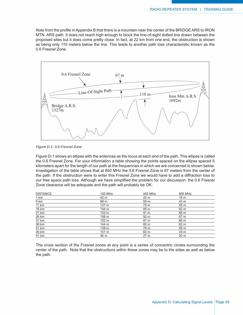
RADIO REPEATER SYSTEM | TRAINING GUIDE
Appendix D: Calculating Signal Levels Page 49
Note from the profi le in Appendix B that there is a mountain near the center of the BRIDGE ARS to IRON MTN. ARS path. It does not reach high enough to block the line-of-sight dotted line drawn between the proposed sites but it does come pretty close. In fact, at 22 km from one end, the obstruction is shown as being only 110 meters below the line. This leads to another path loss characteristic known as the 0.6 Fresnel Zone.
Figure D-1: 0.6 Fresnel Zone
Figure D-1 shows an ellipse with the antennas as the locus at each end of the path. This ellipse is called the 0.6 Fresnel Zone. For your information a table showing the points spaced on the ellipse spaced 5 kilometers apart for the length of our path at the frequencies in which we are concerned is shown below. Investigation of the table shows that at 850 MHz the 0.6 Fresnel Zone is 67 meters from the center of the path. If the obstruction were to enter this Fresnel Zone we would have to add a diffraction loss to our free space path loss. Although we have simplifi ed the problem for our discussion, the 0.6 Fresnel Zone clearance will be adequate and the path will probably be OK.
DISTANCE 150 MHz 450 MHz 850 MHz1 km 42 m 25 m 18 m6 km 99 m 59 m 43 m11 km 127 m 75 m 55 m16 km 144 m 85 m 62 m21 km 153 m 91 m 66 m26 km 156 m 92 m 67 m31 km 153 m 91 m 66 m36 km 144 m 85 m 62 m41 km 128 m 76 m 55 m46 km 101 m 60 m 43 m51 km 46 m 27 m 20 m
The cross section of the Fresnel zones at any point is a series of concentric circles surrounding the center of the path. Note that the obstructions within these zones may be to the sides as well as below the path.
67 m
110 m
0.6 Fresnel Zone
Line-Of-Sight Path
Bridge A.R.S.1327m
Iron Mtn A.R.S.1692m

TRAINING GUIDE | RADIO REPEATER SYSTEM
Appendix D: Calculating Signal LevelsPage 50
This Page Intentionally Left Blank

RADIO REPEATER SYSTEM | TRAINING GUIDE
Appendix E: Mobile Coverage Tests Page 51
APPENDIX E: MOBILE COVERAGE TESTS
Mobile coverage tests will give you an accurate representation of the coverage area of a repeater site. Use two radios for the mobile coverage test, one radio (typically a mobile) for transmitting at pre-determined mobile test points, and the other at the proposed repeater site. A portable or mobile must be used at the repeater site that is the same RF power output of the fi nal repeater to be installed. Using a 25 watt mobile for coverage tests does not tell you much if you are going to replace it eventually with a 2 watt repeater. It is important that the power output of both the radios be tested and noted at the beginning and end of the test. Fresh batteries should be used.
For the repeater site radio, use a switched attenuator which will be installed in series with a temporary antenna (a whip on a 9 meter (30 ft.) mast will do). DO NOT TRANSMIT THROUGH THE ATTENUATOR as it will be severely damaged. The set-up is shown in Figure E-1
Figure E-1: Switched Attenuator
Test Portable
From Mobile atTest Points
Whip or GroundPlane Antenna
Switched attenuator
REMOVE WHEN TRANSMITTING

TRAINING GUIDE | RADIO REPEATER SYSTEM
Appendix E: Mobile Coverage TestsPage 52
Lay out a route for the mobile with test points approximately 1 km (0.6 miles) apart using your coverage map as a reference as shown in Figure E-2.
Figure E-2: Mobile Coverage Test Points
This route should include a couple of points that are line-of-sight just to confi rm that everything is working properly. When the mobile stops at the test point, have it transmit long enough so that you have time to switch the attenuator to the point where the signal gets noisy just before it disappears. Have the portable (repeater site) squelch set at the threshold for these tests. Make notes showing the amount of attenuation necessary to switch the signal into the noise at each test point (use the example coverage test sheet in Appendix I). When completed, you should have a list of test points, most of which will be in questionable areas of coverage, with attenuator values noted for each. Next it is necessary to reduce each of the attenuator fi gures by an amount equal to the average (start of test to end of test) power output of the mobile in excess of 1 watt.
Office
+ Proposed Site
TP1
TP2TP3
TP4TP10
TP11TP12
Etc.
Etc.
TP = Test Point
4000
5000
3000
6562
5000
3000
5023
4000
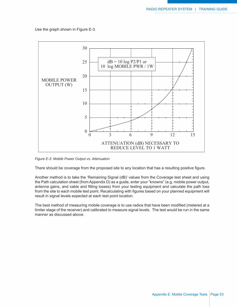
RADIO REPEATER SYSTEM | TRAINING GUIDE
Appendix E: Mobile Coverage Tests Page 53
Use the graph shown in Figure E-3.
Figure E-3: Mobile Power Output vs. Attenuation
There should be coverage from the proposed site to any location that has a resulting positive fi gure.
Another method is to take the ‘Remaining Signal (dB)’ values from the Coverage test sheet and using the Path calculation sheet (from Appendix D) as a guide, enter your “knowns” (e.g. mobile power output, antenna gains, and cable and fi tting losses) from your testing equipment and calculate the path loss from the site to each mobile test point. Recalculating with fi gures based on your planned equipment will result in signal levels expected at each test point location.
The best method of measuring mobile coverage is to use radios that have been modifi ed (metered at a limiter stage of the receiver) and calibrated to measure signal levels. The test would be run in the same manner as discussed above.
MOBILE POWEROUTPUT (W)
ATTENUATION (dB) NECESSARY TOREDUCE LEVEL TO 1 WATT
0
5
10
15
20
25
0 3 6 9 12 15
30
dB = 10 log P2/P1 or10 log MOBILE PWR / 1W

TRAINING GUIDE | RADIO REPEATER SYSTEM
Appendix E: Mobile Coverage TestsPage 54
This Page Intentionally Left Blank
RADIO REPEATER SYSTEM | TRAINING GUIDE
Appendix F: Examples of Antenna Data Page 55
APPENDIX F: EXAMPLES OF ANTENNA DATA
On the following pages are examples of Antenna Data sheets.

TRAINING GUIDE | RADIO REPEATER SYSTEM
Appendix F: Examples of Antenna DataPage 56
Figure F-1: 150 MHz Broadband Dipole Characteristics
Radiation Patterns For VerticalAnd Horizontal Polarization.
Horizontal Radiation PatternsFor Vertical Polarization.
+10°
0
OMNI
dB RE l /2 DIPOLE-10 -5 0 5-10-505
-10 -5 0 5-50
+10°
0
-10°
dB RE l /2 DIPOLE
VERTICAL
HORIZONTAL
-10 10
Characteristics of a 150 MHz, Two-Element Broadband Dipole.
Characteristics of a 400 MHz, Seven-Element Yagi.
Electrical Specifications Omni Offset
Mechanical Specifications
Electrical Specifications
Mechanical Specifications
Frequency Range:Nominal Gain:Bandwidth, 1.5:1 VSWR:Horizontal Beamwidth:(half power points)
Power Rating:Polarization:
Lightning Protection:Termination:
132 - 1743 6
10170 (Offset)
300Vertical
DC GroundType "N" Male
MHzdBd
MHzDeg.
Watts
Vertical Beamwidth:(half power points)
Deg.
Pattern: Omni or Offset
34
Length:
Rated Wind Velocity:Rated Wind Velocity:(with 0.5 in radial ice)
km/h (mph)
kg (lbs.)mm (in.) 2896 (114)
km/h (mph)
Horizontal Thrust at ratedwind velocity and ice load:
Weight:
kg (lbs.)
7.7 (17)193 (120)129 (80)
29.5 (65)
Frequency Range:Nominal Gain:Bandwidth, 1.5:1 VSWR:Horizontal Beamwidth:(half power points)
Power Rating:Polarization:
Lightning Protection:Termination:
406 - 512102041
250Vert. or Horiz.
DC GroundType "N" Male
MHzdBd
MHzDeg.
Watts
Vertical Beamwidth:(half power points)
Deg.
Pattern: Directional
50
Front To Back Ratio 20dB
Length:
Rated Wind Velocity:Rated Wind Velocity:(with 0.5 in radial ice)
km/h (mph)
kg (lbs.)
mm (in.) 914 (36)
km/h (mph)
Horizontal Thrust at ratedwind velocity / ice load:
Weight:
kg (lbs.)
2.3 (5)300 (187)182 (113)
23 (51)
mm (in.)Width: 330 (13)
OFFSET
-10°

RADIO REPEATER SYSTEM | TRAINING GUIDE
Appendix F: Examples of Antenna Data Page 57
Figure F-2: 400 and 800 MHz Corner Refl ector Characteristics
+10°
0
-10°
dB RE l /2 DIPOLE-10 -5 0 5 10-10-50510
21
1. Vertical Radiation Pattern for Horizontal Polarization2. Horizontal Radiation Pattern for Horizontal Polarization
Mechanical SpecificationsHeight:
Weight:Rated Wind Velocity:Rated Wind Velocity:(with 0.5 in radial ice)
km/h (mph)
kg (lbs.)
mm (in.) 762 (30)
km/h (mph)
Horizontal Thrust at ratedwind velocity and ice load:
Width:Depth:
mm (in.)mm (in.)
kg (lbs.)
1219 (48) 610 (24)1270 (50) 1219 (48)
N / A 457 (18)10.5 (23) 17.2 (38) 10.5 (23)
201 (125) 161 (100)137 (85)
74.8 (165) 150 (330) 76.8 (169)
Electrical SpecificationsFrequency Range:Nominal Gain:Bandwidth, 1.5:1 VSWR:Horizontal Beamwidth:(half power points)
Power Rating:Polarization:
Lightning Protection:Termination:
406 - 470 or 450 - 512 800 - 9009.5 12
406 - 470 or 450 - 512 10060 40 52
100Vertical or Horizontal
DC GroundType "N" Male
MHzdBd
MHzDeg.
Watts
Vertical Beamwidth:(half power points)
Deg.
Front to Back Ratio: dB
Pattern: Directional
10
45 34 30
20 25 30
Radiation Patterns For Vertical Polarization.Characteristics of 400 and 800 MHz Corner Reflectors.

TRAINING GUIDE | RADIO REPEATER SYSTEM
Appendix F: Examples of Antenna DataPage 58
Figures F-3 and F-4: 400 MHz Radafl ector Characteristics
+10°
0
-10°
dB RE l /2 DIPOLE-10 -5 0 +5 +10-10-50+5+10 +15
Vertical Radiation Pattern for Horizontal Polarization
Mechanical SpecificationsHeight:
Weight:Rated Wind Velocity:Rated Wind Velocity:(with 0.5 in radial ice)
km/h (mph)
kg (lbs.)
mm (in.) 2083 (82)
km/h (mph)
Horizontal Thrust at ratedwind velocity and ice load:
Width: mm (in.)
kg (lbs.)
1041 (41)
161 (100)136.7 (85)
113 (250)
Electrical SpecificationsFrequency Range:
Nominal Gain:Bandwidth, 1.5:1 VSWR:
Horizontal Beamwidth:(half power points)
Power Rating:Polarization:
Lightning Protection:Termination:
15406 - 420450 - 470
32
250Vertical or Horizontal
DC GroundType "N" Male
MHz
dBdMHz
Deg.
Watts
Vertical Beamwidth:(half power points)
Deg.
Front to Back Ratio: dB
Pattern: Directional
18
24
406 - 420450 - 470
11.3 (25)
Characteristics of a 400 MHz Radaflector.
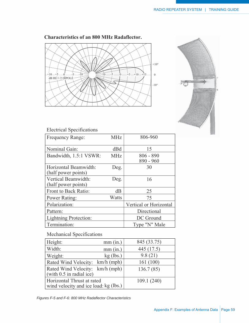
RADIO REPEATER SYSTEM | TRAINING GUIDE
Appendix F: Examples of Antenna Data Page 59
Figures F-5 and F-6: 800 MHz Radafl ector Characteristics
Mechanical SpecificationsHeight:
Weight:Rated Wind Velocity:Rated Wind Velocity:(with 0.5 in radial ice)
km/h (mph)
kg (lbs.)
mm (in.)
km/h (mph)
Horizontal Thrust at ratedwind velocity and ice load:
Width: mm (in.)
kg (lbs.)
Electrical SpecificationsFrequency Range:
Nominal Gain:Bandwidth, 1.5:1 VSWR:
Horizontal Beamwidth:(half power points)
Power Rating:Polarization:
Lightning Protection:Termination:
MHz
dBdMHz
Deg.
Watts
Vertical Beamwidth:(half power points)
Deg.
Front to Back Ratio: dB
Pattern:
845 (33.75)445 (17.5)9.8 (21)
161 (100)136.7 (85)
109.1 (240)
806-960
15
30
Vertical or Horizontal
DC GroundType "N" Male
Directional
16
25
806 - 890890 - 960
75
+10°
0
-10°
dB RE l /2 DIPOLE-50+5+10 -10 -10 -5 0 +5 +10 +15
Characteristics of an 800 MHz Radaflector.

TRAINING GUIDE | RADIO REPEATER SYSTEM
Appendix F: Examples of Antenna DataPage 60
This Page Intentionally Left Blank
RADIO REPEATER SYSTEM | TRAINING GUIDE
Appendix G: Examples of Duplexer Data Page 61
APPENDIX G: EXAMPLES OF DUPLEXER DATA
On the following pages are isolation and insertion loss characteristics for a variety of duplexers.
The 150 MHz duplexer exhibits 70 dB isolation with 1.5 dB insertion loss at a minimum frequency separation of 500 KHz. Isolation and insertion loss fi gures would improve greatly with larger separations. Isolation of 70 dB and an insertion loss of 0.8 dB may be possible at a spacing of 3 MHz.
The 400 MHz duplexer exhibits 75 dB isolation with 0.8 dB insertion loss at a minimum frequency separation of 5.0 MHz.
The 800 MHz duplexer exhibits 70 dB isolation with 1.0 dB insertion loss at a minimum frequency separation of 3.6 MHz.
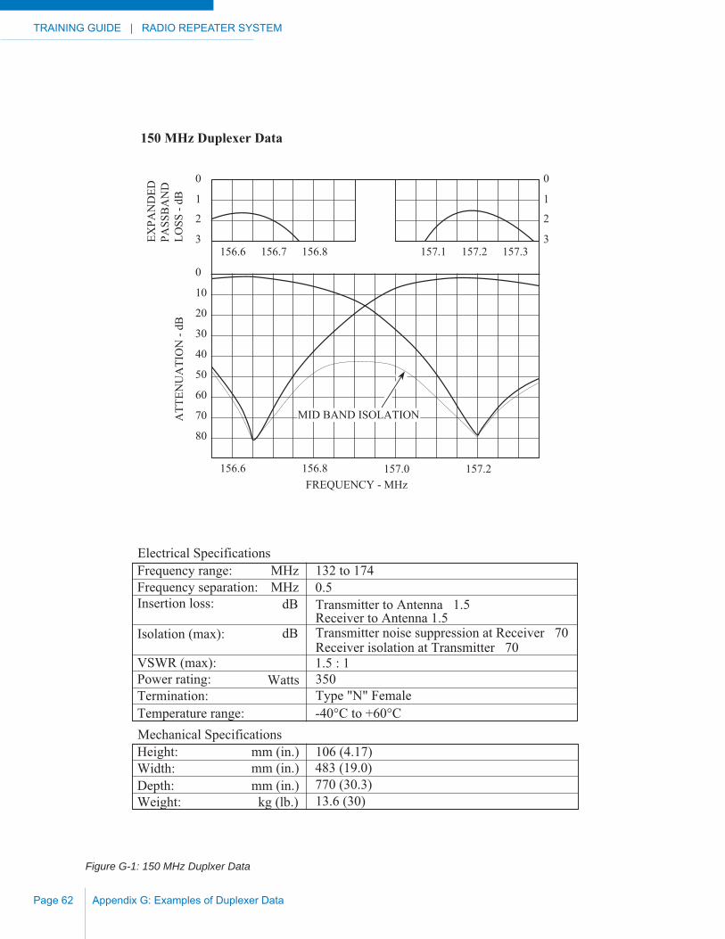
TRAINING GUIDE | RADIO REPEATER SYSTEM
Appendix G: Examples of Duplexer DataPage 62
Figure G-1: 150 MHz Duplxer Data
0
1
2
3
0
1
2
3156.6 156.7 156.8 157.1 157.2 157.3
EXPA
ND
EDPA
SSB
AN
DLO
SS -
dBA
TTEN
UA
TIO
N -
dB
0
10
20
30
40
50
60
70
80
156.6 156.8 157.0 157.2FREQUENCY - MHz
MID BAND ISOLATION
Mechanical SpecificationsHeight: 106 (4.17)Width: 483 (19.0)Depth: 770 (30.3)Weight: 13.6 (30)
mm (in.)mm (in.)mm (in.)kg (lb.)
Electrical SpecificationsFrequency range: MHz 132 to 174Frequency separation: MHz 0.5Insertion loss: dB Transmitter to Antenna 1.5
Receiver to Antenna 1.5Isolation (max): dB Transmitter noise suppression at Receiver 70
Receiver isolation at Transmitter 70VSWR (max): 1.5 : 1Power rating: Watts 350Termination: Type "N" FemaleTemperature range: -40°C to +60°C
150 MHz Duplexer Data

RADIO REPEATER SYSTEM | TRAINING GUIDE
Appendix G: Examples of Duplexer Data Page 63
Figure G-2: 400 MHz Duplxer Data
01
2
3
01
2
3450 451 452 455 456 457EX
PAN
DED
PASS
BA
ND
LOSS
- dB
ATT
ENU
ATI
ON
- dB
0
10
20
30
40
50
60
70
80
450 451FREQUENCY - MHz
MID BAND ISOLATION
452 453 454 455 456 457
Mechanical SpecificationsHeight: 88.9 (3.5)Width: 483 (19.0)Depth: 266.5 (10.5)Weight: 4.54 (10)
mm (in.)mm (in.)mm (in.)
kg (lb.)
Electrical SpecificationsFrequency range: MHz 450 to 470Frequency separation: MHz 5.0Insertion loss: dB Transmitter to Antenna 0.8
Receiver to Antenna 0.8Isolation (max): dB Transmitter noise suppression at Receiver 75
Receiver isolation at Transmitter 75VSWR (max): 1.5 : 1Power rating: Watts 125Termination: Type "N" FemaleTemperature range: -40°C to +60°C
400 MHz Duplexer Data

TRAINING GUIDE | RADIO REPEATER SYSTEM
Appendix G: Examples of Duplexer DataPage 64
Figure G-3: 800 MHz Duplxer Data
0
1
2
0
1
2805 806 807 850 851 852
ATT
ENU
ATI
ON
- dB
0
10
20
30
40
50
60
70
80
790 800FREQUENCY - MHz
810 820 830 840 860 870
806
851
2.0 : 11.5 : 11.0 : 1
90
VSWR
850
Mechanical SpecificationsHeight: 106 (4.17)Width: 483 (19.0)Depth: 210 (8.25)Weight: 5.44 (12)
mm (in.)mm (in.)mm (in.)kg (lb.)
Electrical SpecificationsFrequency range: MHz 806 to 960Frequency separation: MHz 3.6Insertion loss: dB Transmitter to Antenna 1.0
Receiver to Antenna 1.0Isolation (max): dB Transmitter noise suppression at Receiver 70
Receiver isolation at Transmitter 70VSWR (max): 1.5 : 1Power rating: Watts 150Termination: Type "N" FemaleTemperature range: -40°C to +60°C
800 MHz Duplexer Data

RADIO REPEATER SYSTEM | TRAINING GUIDE
Appendix H: Examples of Cable & Connector Losses Page 65
APPENDIX H: EXAMPLES OF CABLE & CONNECTOR LOSSES
Coaxial Cable losses
Nominal Attenuation in dB per 100 meters of Cable (dB per 100 feet)
50 OHM CABLES 50 MHz 150 MHz 450 MHz 850 MHzType Meters (Feet) Meters (Feet) Meters (Feet) Meters (Feet)RG-58 C/U 10.8 (3.30) 20.0 (6.10) 35.5 (11.75) 58.2 (17.75)RG-188 A/U 25.9 (7.90) 43.5 (13.3) 68.3 (20.83) 87.5 (26.66)RG-213/U 4.9 (1.50) 8.9 (2.70) 16.3 (4.97) 24.7 (7.53)RG-8 FOAM 3.9 (1.20) 7.2 (2.20) 13.0 (3.98) 17.0 (5.20)RG-303/U 8.8 (2.70) 15.1 (4.60) 27.6 (8.42) 37.0 (11.3)RG-393/U 4.6 (1.40) 8.5 (2.60) 15.6 (4.75) 21.3 (6.50)LDF4-50A 1.6 (0.48) 2.8 (0.84) 5.2 (1.57) 6.8 (2.06)LDF5-50A 0.8 (0.26) 1.4 (0.44) 2.6 (0.79) 3.7 (1.12)LDF7-50A 0.6 (0.17) 0.92 (0.28) 1.7 (0.53) 2.3 (0.71)
Estimated Coaxial Connector Losses
The attenuation caused by a coaxial connector is dependent on the exact type of connector used and the mechanical quality of the connection itself. To avoid unnecessary complications most licensing authorities accept the following values as being acceptable in calculating effective radiated power, fade margins and path losses:
At 150 MHz 0.25 dB per connection.
At 450 MHz 0.50 dB per connection.
At 850 MHz 0.60 dB per connection.

TRAINING GUIDE | RADIO REPEATER SYSTEM
Appendix H: Examples of Cable & Connector LossesPage 66
This Page Intentionally Left Blank

RADIO REPEATER SYSTEM | TRAINING GUIDE
Appendix I: Blank Worksheets Page 67
APPENDIX I: BLANK WORKSHEETS
The following pages are blank worksheets that are provided for your use. Feel free to photocopy or print these pages.
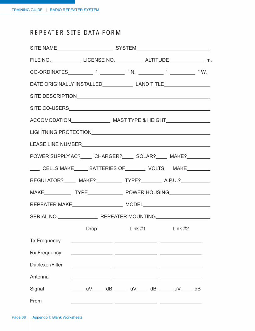
TRAINING GUIDE | RADIO REPEATER SYSTEM
Appendix I: Blank WorksheetsPage 68
REPEATER SITE DATA FORM
SITE NAME SYSTEM
FILE NO. LICENSE NO. ALTITUDE m.
CO-ORDINATES ‘ “ N. ‘ “ W.
DATE ORIGINALLY INSTALLED LAND TITLE
SITE DESCRIPTION
SITE CO-USERS
ACCOMODATION MAST TYPE & HEIGHT
LIGHTNING PROTECTION
LEASE LINE NUMBER
POWER SUPPLY AC? CHARGER? SOLAR? MAKE?
CELLS MAKE BATTERIES OF VOLTS MAKE
REGULATOR? MAKE? TYPE? A.P.U.?
MAKE TYPE POWER HOUSING
REPEATER MAKE MODEL
SERIAL NO. REPEATER MOUNTING
Drop Link #1 Link #2
Tx Frequency
Rx Frequency
Duplexer/Filter
Antenna
Signal uV dB uV dB uV dB
From
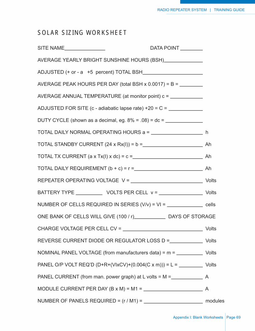
RADIO REPEATER SYSTEM | TRAINING GUIDE
Appendix I: Blank Worksheets Page 69
SOLAR SIZ ING WORKSHEET
SITE NAME DATA POINT
AVERAGE YEARLY BRIGHT SUNSHINE HOURS (BSH)
ADJUSTED (+ or - a +5 percent) TOTAL BSH
AVERAGE PEAK HOURS PER DAY (total BSH x 0.0017) = B =
AVERAGE ANNUAL TEMPERATURE (at monitor point) c =
ADJUSTED FOR SITE (c - adiabatic lapse rate) +20 = C =
DUTY CYCLE (shown as a decimal, eg. 8% = .08) = dc =
TOTAL DAILY NORMAL OPERATING HOURS a = h
TOTAL STANDBY CURRENT (24 x Rx(I)) = b = Ah
TOTAL TX CURRENT (a x Tx(I) x dc) = c = Ah
TOTAL DAILY REQUIREMENT (b + c) = r = Ah
REPEATER OPERATING VOLTAGE V = Volts
BATTERY TYPE VOLTS PER CELL v = Volts
NUMBER OF CELLS REQUIRED IN SERIES (V/v) = VI = cells
ONE BANK OF CELLS WILL GIVE (100 / r) DAYS OF STORAGE
CHARGE VOLTAGE PER CELL CV = Volts
REVERSE CURRENT DIODE OR REGULATOR LOSS D = Volts
NOMINAL PANEL VOLTAGE (from manufacturers data) = m = Volts
PANEL O/P VOLT REQ’D (D+R+(VIxCV)+(0.004(C x m))) = L = Volts
PANEL CURRENT (from man. power graph) at L volts = M = A
MODULE CURRENT PER DAY (B x M) = M1 = A
NUMBER OF PANELS REQUIRED = (r / M1) = modules
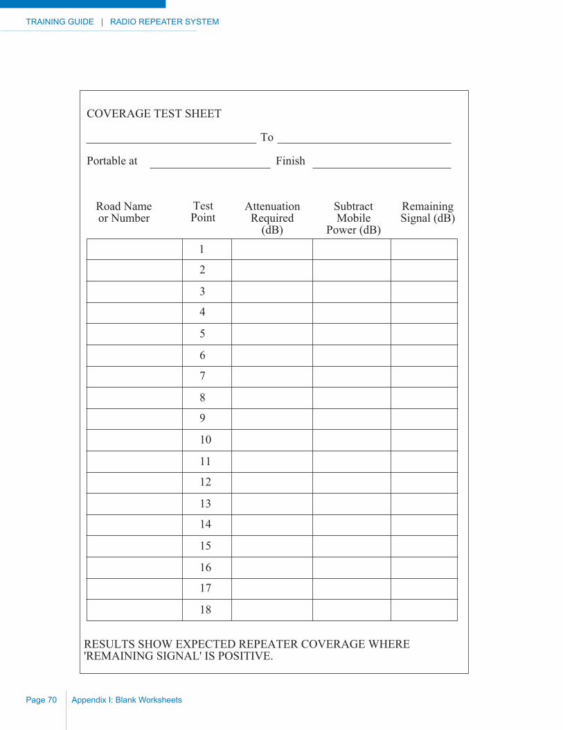
TRAINING GUIDE | RADIO REPEATER SYSTEM
Appendix I: Blank WorksheetsPage 70
1
2
3
4
5
6
7
8
9
10
11
12
13
14
15
16
17
18
Road Nameor Number
TestPoint
AttenuationRequired
(dB)
SubtractMobile
Power (dB)
RemainingSignal (dB)
COVERAGE TEST SHEET
To
Portable at Finish
RESULTS SHOW EXPECTED REPEATER COVERAGE WHERE 'REMAINING SIGNAL' IS POSITIVE.
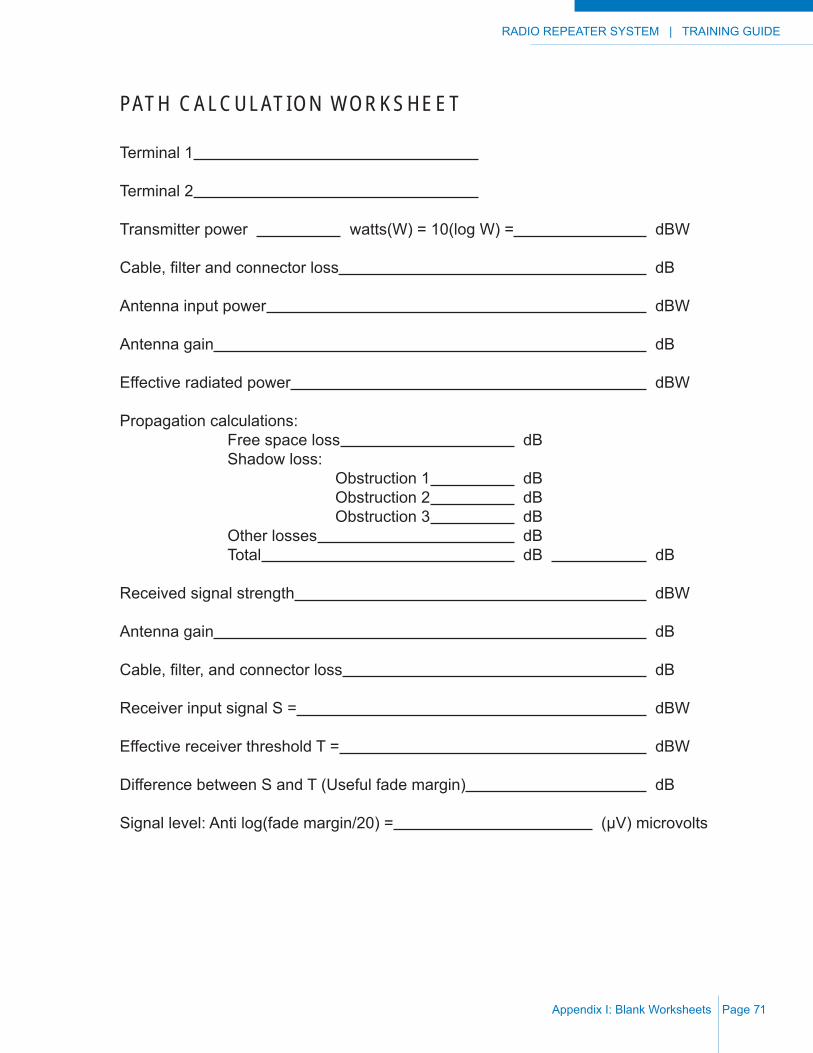
RADIO REPEATER SYSTEM | TRAINING GUIDE
Appendix I: Blank Worksheets Page 71
PATH CALCULATION WORKSHEET
Terminal 1
Terminal 2
Transmitter power watts(W) = 10(log W) = dBW
Cable, fi lter and connector loss dB
Antenna input power dBW
Antenna gain dB
Effective radiated power dBW
Propagation calculations: Free space loss dB Shadow loss: Obstruction 1 dB Obstruction 2 dB Obstruction 3 dB Other losses dB Total dB dB
Received signal strength dBW
Antenna gain dB
Cable, fi lter, and connector loss dB
Receiver input signal S = dBW
Effective receiver threshold T = dBW
Difference between S and T (Useful fade margin) dB
Signal level: Anti log(fade margin/20) = (μV) microvolts
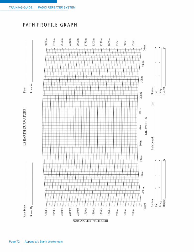
TRAINING GUIDE | RADIO REPEATER SYSTEM
Appendix I: Blank WorksheetsPage 72
PATH PROFILE GRAPH
250m
500m
750m
1000
m
1250
m
1500
m
1750
m
2000
m
2250
m
2500
m
2750
m
3000
m
250m
500m
750m
1000
m
1250
m
1500
m
1750
m
2000
m
2250
m
2500
m
2750
m
3000
m
HEIGHT 50m PER DIVISION
50km
40km
30km
20km
10km
0km
10km
20km
30km
40km
50km
4/3
EAR
TH C
UR
VA
TUR
EM
ap S
cale
___
____
____
____
____
____
____
___
Dra
wn
By
____
____
____
____
____
____
____
__
Dat
e __
____
____
____
____
____
____
____
___
Loca
tion
____
____
____
____
____
____
____
__
KIL
OM
ETR
ES
Stat
ion
Lat.
°
'
"
Long
.
°
'
"
Hei
ght
m
Stat
ion
La
t.
°
'
"Lo
ng.
°
'
"H
eigh
t
m
Path
Len
gth
km
RADIO REPEATER SYSTEM | TRAINING GUIDE
Appendix J: Glossary of Terms Page 73
APPENDIX J: GLOSSARY OF TERMS
AntennaAn elevated device for radiating and receiving radio waves. It changes electrical currents into electromagnetic radio waves and vice versa.
Antenna GainThe increase in power radiated by and / or received by an antenna in a given direction compared to the power radiated in the same direction by a standard omni-directional antenna.
Antenna PolarizationThe orientation of the radiated electric fi eld in relation to the surface of the earth.
Antenna ArrayAn arrangement of two or more antennas spaced and connected so that they are in phase and their effects are additive.
AttenuationThe reduction in energy which accompanies the passage of an electronic wave through telephone lines, equipment or space.
Automatic Frequency Control (AFC)A circuit that allows a receiver to “lock on” to a transmitter’s signal, and follow any deviations that may occur in the transmitter’s frequency.
Auxiliary Power Unit (APU)A machine or device that supplies power, usually electrical, when the main or usual source fails or is interrupted. A standby power source.
Band, FrequencyFrequencies which are within two defi ned limits, and are used for the specifi ed purpose.
BandwidthThe amount or portion of the frequency spectrum required to transmit the desired information.
Base StationA transmitter / receiver unit located in a fi xed location. Term is often shortened to “base”.
BeamA confi guration of radiated energy whose rays are sharply directional and parallel.
Beam AntennaAn antenna array that concentrates radio transmission into a narrow directional path or receives radio signals only from a narrow sector of the total horizon.
TRAINING GUIDE | RADIO REPEATER SYSTEM
Appendix J: Glossary of TermsPage 74
BroadbandThe ability of a circuit such as an amplifi er, transmitter, receiver or antenna to be useful over a wide frequency range.
Broadband AntennaA transmitting or receiving antenna that performs almost uniformly over a wide frequency band without needing adjustment.
Call SignIdentifying letters and numbers for a radio station or transmitter.
CarrierA radio wave, current or voltage used for transmitting intelligence. When no intelligence is being transmitted, such as during a pause in communications, only the unmodulated carrier signal is present.
ChannelA narrow band of frequencies including the assigned carrier frequency, within which a radio system must operate in order to prevent interference with stations on adjacent channels.
Conformal CoatingA coating applied to completed circuit boards to inhibit corrosion and fungus growths.
Control StationA base station, the transmissions of which are used to control the operation of another fi xed station such as a repeater. The term is also used, in the operating context, as the station operator who directs other operators in system usage.
Corrosion InhibitorsChemicals that inhibit the corrosive effects of certain atmospheres. e.g.: moisture.
CrystalA thin slab of natural or man-made quartz which, when subjected to the proper electrical excitation, will vibrate or oscillate at a specifi c frequency. A quartz crystal is a major component in oscillators used in radio transmitters and receivers.
dBAbbreviation for decibel. See decibel.
DecibelA unit of relative voltage or power. One-tenth of a Bel. Roughly the smallest change that the human ear can detect. The decibel is also used to compare relative differences of signal voltages, or power.
DecoderA device that translates coded intelligence into usable form.
DistortionUnfaithful reproduction of audio signals due to changes occurring in the waveform of the original signal somewhere in the course of its transmission, reception or amplifi cation.
Drip LoopA small circle (20 - 30 cm diameter) of coaxial cable used at a cable entrance to a building to discourage the entry of moisture on the cable surface.
Drop RepeaterA local coverage repeater.
EmissionThe process of radiating radio waves into space from a transmitter.
EncoderA device that translates intelligence into a form easier to transmit over a radio system.
FadeTo decrease gradually in signal strength.
Fade MarginThe difference between the level of the received signal and the receiver threshold. Usually expressed in decibels.
RADIO REPEATER SYSTEM | TRAINING GUIDE
Appendix J: Glossary of Terms Page 75
Forward GainSee “gain”.
Four-Wire LineTwo separate two-wire lines, one for receiving and the other for transmitting in remote control operations.
FrequencyThe number of complete cycles per second of alternating current or radio waves. Usually measured in Hertz (Hz).
Frequency BandA continuous range of frequencies extending between two limiting frequencies. Common frequency bands in two-way radio are 29-50 MHz (low band), 136-174 MHz (VHF or High Band), 406-512 MHz, 806-824 MHz, 851-869 MHz , 869-901 MHz and 935-940 MHz (UHF Bands).
Frequency Modulation (FM)A method of modulating a carrier frequency by causing the frequency to vary above and below the carrier in accordance with the sound being transmitted. The amount of deviation in frequency above and below the carrier frequency is proportional to the amplitude of the sound being transmitted. The advantages of this system are almost complete freedom from atmospheric and man-made interference.
Frequency RangeA frequency band including the frequencies at which a system is able to transmit, receive or amplify power.
Fresnel ZoneA measurement of path clearance in terms of the effect at the frequency in question. The First Fresnel Zone is the surface containing every point for which the sum of the distances from that point to the two ends is one-half wavelength longer than the direct end-to-end path.
Front-To-Back Ratio (F/B)The ratio between the power radiated in the forward direction from an antenna to that radiated to the rear.
GainThe increase in voltage, current or power as measured (usually in dB) against an established standard.
Gain AntennaAn antenna designed to increase its normal fi eld range through a more directional pattern.
GroundedConnected to earth or some conducting body that serves in place of the earth.
HarmonicFrequencies which are a multiple of a carrier frequency.
Hertz (Hz)The unit of frequency measurement equal to one cycle per second.
HysteresisThe lag of an effect in respect to its cause.
InterfaceA method for interconnecting units or systems which may not be compatible.
InterferenceThe effects that occur when undesired signals interfere with the reception of a desired signal.
IntermodulationThe product of two waves beating together and producing other interfering waves. Sometimes called “intermod” or “IM”.
Kilohertz (kHz)One thousand Hertz or one thousand cycles per second.
Line-Of-Sight Distance (L/S)The straight-line distance from station to station or horizon. This represents the approximate normal transmitting range of stations in the VHF and UHF bands.
TRAINING GUIDE | RADIO REPEATER SYSTEM
Appendix J: Glossary of TermsPage 76
Link RepeaterA repeater used to link two or more repeater sites together.
Megahertz (MHz)One million Hertz or one million cycles per second.
Messenger CableA well secured cable between a building and a pole or tower to which other cables may be attached thereby reducing the strain.
MicrowaveThat portion of the frequency spectrum above 1000 MHz.
MobileEquipment designed for vehicular or portable operation.
ModulateTo vary the amplitude, frequency or phase of a radio signal, in order to transmit intelligence.
NoiseInterference caused by either internal or external sources.
OscillatorA circuit that produces an alternating output current of a certain frequency determined by the characteristics of the circuit components.
Path LossThe reduction or attenuation of signal strength that occurs between the transmitter and receiver.
Phone PatchAn interconnecting device between a telephone system and a radio system.
Portable RadioA completely self-contained two-way radio.
PropagationThe radiation of electromagnetic waves.
Radio Frequency (RF)See “frequency”
Radio ReceiverA device which amplifi es radio frequency signals, separates the intelligence signal from the RF carrier, amplifi es it, and converts it back to the original sound waves.
Radio SpectrumThe entire range of useful radio waves as classifi ed into nine bands by the International Telecommunications Union.
Radio InterferenceInterference caused by the radio waves of a station or stations other than that from which reception is desired.
Radio WaveA combination of electric and magnetic fi elds varying at a radio frequency, and capable of traveling through space at the speed of light. It is produced by feeding the output of a radio transmitter to an antenna.
Random NoiseA term for irregular disturbances of an electrical nature.
Remote ControlThe operation of a base station from a distance using telephone lines or a radio circuit.
RepeaterA radio station that automatically re-broadcasts radio signals that are received on a specifi c frequency.
SignalA variable electronic parameter, such as current or voltage, that is used to convey information through an electronic circuit or system.
Signal PathThe route by which intelligence is conveyed from one point to another.
Signal-To-Noise RatioThe ratio of one parameter of a desired signal to the same or corresponding parameter of the noise.
RADIO REPEATER SYSTEM | TRAINING GUIDE
Appendix J: Glossary of Terms Page 77
SpectrumA range of frequencies within which radiation has some specifi ed characteristic, such as the audio-frequency spectrum, radio spectrum or the ultra-violet spectrum.
SystemA combination of two or more stations established in such a way as to provide communications.
TransceiverA combination of transmitting and receiving equipment that uses some or all of the components jointly in both transmitting and receiving.
TransmissionThe transfer of electrical energy from one location to another.
Transmission LossA term used to denote the loss in power during the transmission of energy from one point to another.
TransmitterThe term applied to the equipment that is used for generating and amplifying an RF carrier signal, modulating this carrier signal with intelligence, and then provide output for an antenna to radiate the modulated signal into space.
Trunk, TrunkingA computer controlled radio system in which many users can share multiple switched repeater equipment while retaining privacy.
Two-Wire LineA telephone line or pair that carries audio in two directions.
Ultra-High Frequency (UHF)The portion of the radio spectrum extending from 300 - 3000 MHz. (Commonly thought of as 300 - 1000 MHz)
Very-High Frequency (VHF)The portion of the radio spectrum extending from 30 - 300 MHz.
Voice FrequencyThe frequency range necessary to faithfully carry ordinary speech. In radio systems voice frequency (VF) range is 300-3000 Hz.
Watt (W)The basic unit of power equal to the voltage multiplied by the current in amperes.
WavelengthIn a periodic wave (frequency), the distance between corresponding points in two consecutive cycles.FSNFAbbreviation for “Fragment Sequence Number Field” in the Common Air Interface.
YagiA directional antenna which usually consists of a radiator, a refl ector and one or more director elements. This antenna exhibits high gain and moderate front-to-back ratio.

TRAINING GUIDE | RADIO REPEATER SYSTEM
Appendix J: Glossary of TermsPage 78
This Page Intentionally Left Blank

Codan Radio Communications43 Erie Street, Victoria, BCCanada, V8V [email protected]
Toll Free Canada and USAPhone: 1-800-664-4066Fax: 1-877-750-0004
InternationalPhone: 250-382-8268Fax: 250-382-6139
©2013 Codan Limited All Rights Reserved.
TG-002-3-0-0
www.codanradio.com