Embed Size (px)
Citation preview
CX-CT6C2.4GHz 6 ChannelFHSS TechnologyDigital ProportionalRadio System
www.copterx.comCopyright © 2011 KY MODEL Company Limited.
INSTRUCTION MANUALINSTRUCTION MANUAL
01
MENU1.2.3.4.
5.15.25.35.4
6.7.8.
9.1.9.2.9.3.9.4.9.5.9.6.10.1.10.2.10.3.10.4.10.5.10.6.10.7.
10.8.10.9.
10.10.10.11.
11.1.11.2.11.3.
12.
Table of contentIntroductionCautionTransmitter Chart2.4G BindingHeli. Connection Diagram (3 Servos CCPM)Airplane Connection DiagramV-Tail COnnection DiagramDELTA-MIX Connection DiagramCX-CT6C Basic FeaturesLED Displaying Board FunctionMenuSystem MenuMODEL.SETPLANE TYPESTICK MODESTICK ADJTRAINERFunction Menu (Heli.)D/RSUB. TRIMTRAVELCH.REVSWASH.MIXGYRO.SENSTHRO.CURVMONITORPIT.CURVTHRO.HOLDFunction Menu for Fixed Wing PlaneFunction Menu for V-TailFunction Menu for Delta MixTechnology Data
12233456677891012121313141617181819192020212122222323
CX-CT6C2.4GHz 6 Channel FHSS TechnologyDigital Proportional Radio System

1. IntroductionThank you for purchasing the CopterX CX-CT6C digital proportional radio system. With advanced micro processor control, large LCD display, glitch free FHSS 2.4GHz system, multiple model memory, build-in program for helicopter, airplane, v-tail and delta wing. Make this one of the most advance radio system in the market. Please keep this manual for future reference.
02
CX-CT6C
2. CautionPlease read this manual carefully and keep it for reference in the future.Warning:1. This product was designed only for radio controlled models;2. The usage of this product should be approved by local relevant law or regulations;3. We will not be responsible for the damages caused by unauthorized modification, adjustment or replacement of parts of this product;4. The manual may be altered without prior notice. Please contact us if you have any corrections or clarifications that should be made in the manual.Please pay more attention to the parts in this manual, which are marked with “Warning”Before starting the transmitter, make sure the transmitter batteries are well loaded and with enough power. And please check and confirm that the servos are all well and properly connected.Please take off batteries from transmitter after flying and during the transportation.Please check and have a test on control surfaces to confirm the transmitter handling of each part prior to each takeoff.Keep the radio system away from moisture, high temperature and strong vibration. Do not clean the product with solvent.Do not fly your models near airfield, schools, hospitals, residences, power transmission network, communication facilities and other places that are forbidden for starting the transmitter. Please stop flying your models with the radio on rainy or windy days, or at night.Do not fly the models when you are tired, sick, intoxicated, or not in good spirit.The antenna does not touch anything else when power switch is turned on.Do not leave this product and its accessories within the reach of small children.Please use this product according to your local relevant law or regulation, we are not responsible for any incidents or damages.
2.4GHz 6 Channel FHSS TechnologyDigital Proportional Radio System
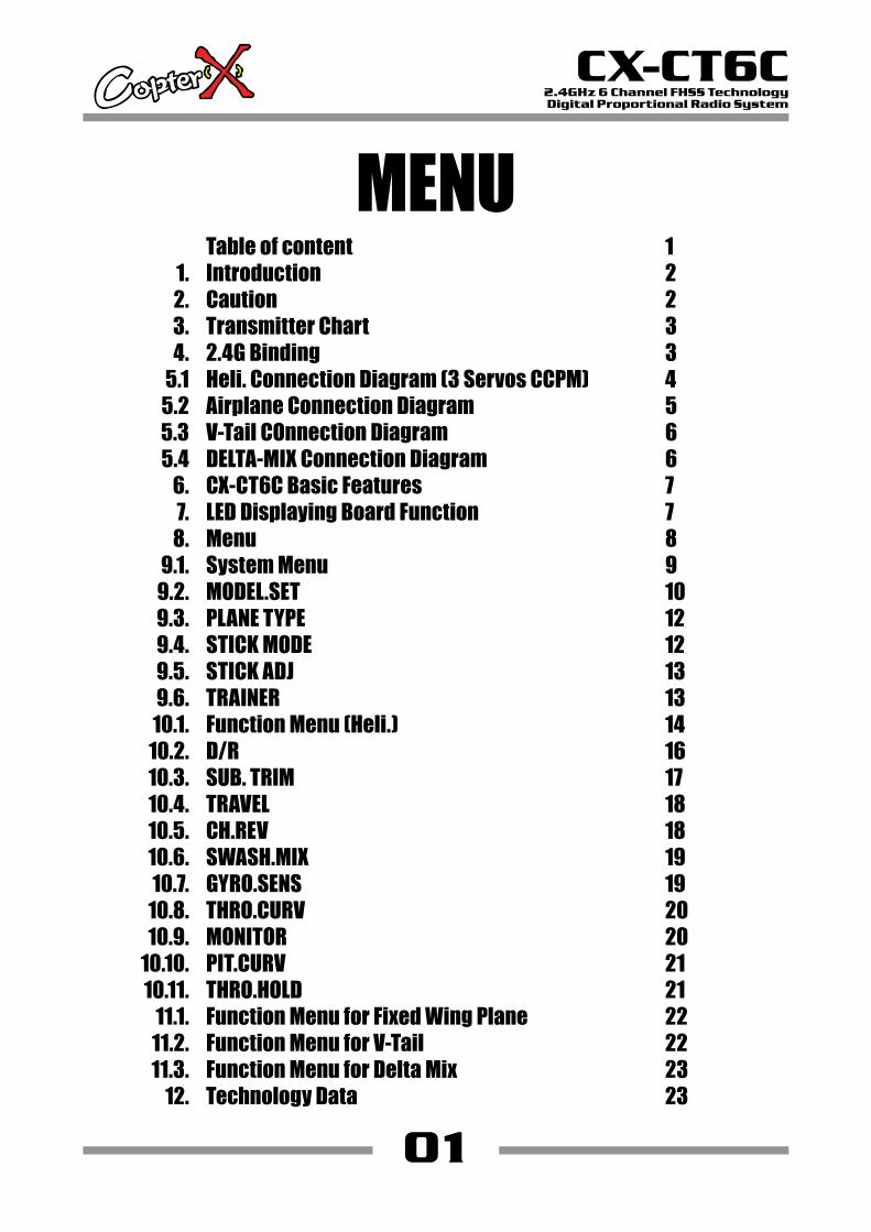
3. Transmitter ChartAntenna
03
CX-CT6C2.4GHz 6 Channel FHSS TechnologyDigital Proportional Radio System
Hover pitch Hover throttle
Digital trim
Digital trim
INCREASE
DECREASEENTER
Right stick
TH. Hold (Heli.)CH 5 (Plane)
GYRO.SENS (Heli.)CH 6 (Plane)
Digital trim
Digital trim
Power switchLCD display
UP
DOWNEXIT
Hook
Left stick
(Heli.) A/E/R DR(Aile, Elev, Rudd)
IDLE switch
Charging jack
4. 2.4G BindingThe binding process: turn on the transmitter, then connect the power of receiver keeping the receiver “BIND” button till the light turn on GREEN which means the binding is successful. After that, it is unnecessary to bind again.Caution: make sure the RX and TX is within one meter, and around 10 meters no similar device. If the light flashing, showing the binding failure, please do again as above indication.
04
CX-CT6C2.4GHz 6 Channel FHSS TechnologyDigital Proportional Radio System
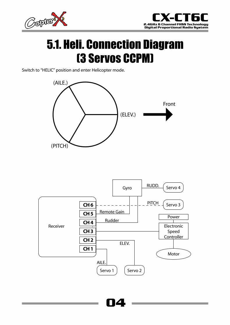
Servo 3
Servo 1
Servo 4Gyro
Receiver
RUDD.
Remote Gain
RudderElectronic
SpeedController
Power
PITCH
ELEV.
AILE.
Motor
Servo 2
Switch to “HELIC” position and enter Helicopter mode.
5.1. Heli. Connection Diagram(3 Servos CCPM)
(AILE.)
(PITCH)
(ELEV.)
Front
05
CX-CT6C2.4GHz 6 Channel FHSS TechnologyDigital Proportional Radio System
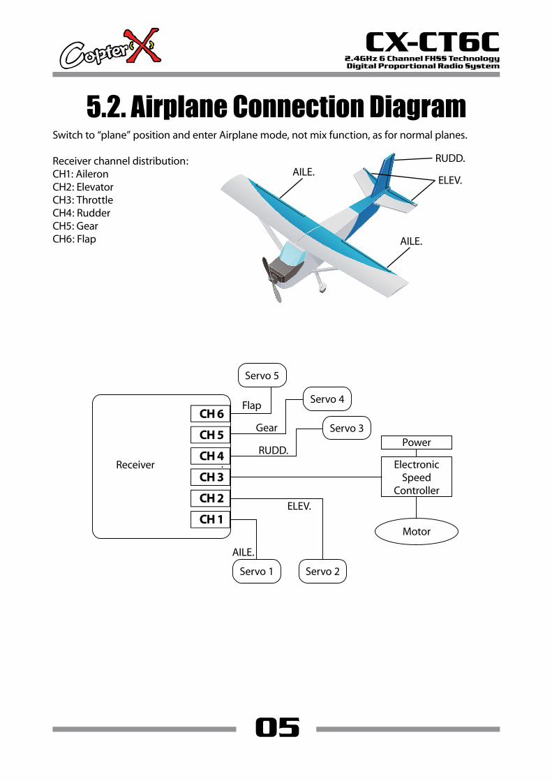
5.2. Airplane Connection DiagramSwitch to “plane” position and enter Airplane mode, not mix function, as for normal planes.
Receiver channel distribution:CH1: AileronCH2: ElevatorCH3: ThrottleCH4: RudderCH5: GearCH6: Flap
AILE.
AILE.
ELEV.
RUDD.
Servo 3
Servo 1
Servo 4
Servo 5
Receiver
Gear
Flap
ElectronicSpeed
Controller
PowerRUDD.
ELEV.
AILE.
Motor
Servo 2

06
CX-CT6C2.4GHz 6 Channel FHSS TechnologyDigital Proportional Radio System
5.3. V-Tail Connection DiagramSwitch to “V-Tail” position and enter V-Tail mode, elevator and Rudder is mixed, as for V-Tail planes.
Receiver channel distribution:CH1: AileronCH2: Ruddervator (Tail)CH3: ThrottleCH4: Ruddervator 2 (Tail)CH5: Aileron2
5.4. DELTA-MIX Connection DiagramSwitch to “DELTA” position and enter DELTA-MIX mode, aileron and elevator is mixed, as for triangle planes, tailless planes, discal planes.
Receiver channel distribution:CH1: EleronCH2: Eleron 2CH3: ThrottleCH4: Rudder
07
CX-CT6C2.4GHz 6 Channel FHSS TechnologyDigital Proportional Radio System
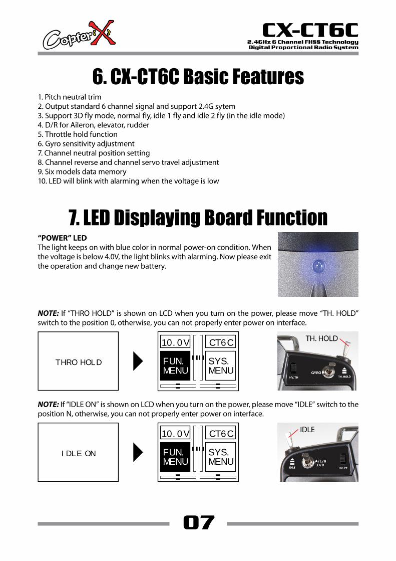
6. CX-CT6C Basic Features1. Pitch neutral trim2. Output standard 6 channel signal and support 2.4G sytem3. Support 3D fly mode, normal fly, idle 1 fly and idle 2 fly (in the idle mode)4. D/R for Aileron, elevator, rudder5. Throttle hold function6. Gyro sensitivity adjustment7. Channel neutral position setting8. Channel reverse and channel servo travel adjustment9. Six models data memory10. LED will blink with alarming when the voltage is low
NOTE: If “THRO HOLD” is shown on LCD when you turn on the power, please move “TH. HOLD” switch to the position 0, otherwise, you can not properly enter power on interface.
NOTE: If “IDLE ON” is shown on LCD when you turn on the power, please move “IDLE” switch to the position N, otherwise, you can not properly enter power on interface.
THRO HOLD
10.0V CT6C
SYS.MENU
FUN.MENU
TH. HOLD
IDLE ON
10.0V CT6C
SYS.MENU
FUN.MENU
IDLE
7. LED Displaying Board Function“POWER” LEDThe light keeps on with blue color in normal power-on condition. When the voltage is below 4.0V, the light blinks with alarming. Now please exit the operation and change new battery.
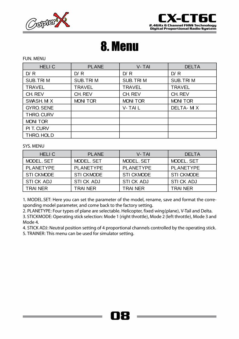
8. MenuFUN. MENU
08
CX-CT6C2.4GHz 6 Channel FHSS TechnologyDigital Proportional Radio System
HELIC PLANE V-TAI DELTA
D/R
SUB.TRIM
TRAVEL
CH.REV
SWASH.MIX
D/R
SUB.TRIM
TRAVEL
CH.REV
MONITOR
GYRO.SENE
D/R
SUB.TRIM
TRAVEL
CH.REV
MONITOR
V-TAIL
D/R
SUB.TRIM
TRAVEL
CH.REV
MONITOR
DELTA-MIX
THRO.CURV
MONITOR
PIT.CURV
THRO.HOLD
SYS. MENU
HELIC PLANE V-TAI DELTA
MODEL.SET
PLANETYPE
STICKMODE
STICK ADJ
TRAINER
MODEL.SET
PLANETYPE
STICKMODE
STICK ADJ
TRAINER
MODEL.SET
PLANETYPE
STICKMODE
STICK ADJ
TRAINER
MODEL.SET
PLANETYPE
STICKMODE
STICK ADJ
TRAINER
1. MODEL.SET: Here you can set the parameter of the model, rename, save and format the corre-sponding model parameter, and come back to the factory setting.2. PLANETYPE: Four types of plane are selectable. Helicopter, fixed wing(plane), V-Tail and Delta.3. STICKMODE: Operating stick selection: Mode 1 (right throttle), Mode 2 (left throttle), Mode 3 and Mode 4.4. STICK ADJ: Neutral position setting of 4 proportional channels controlled by the operating stick.5. TRAINER: This menu can be used for simulator setting.
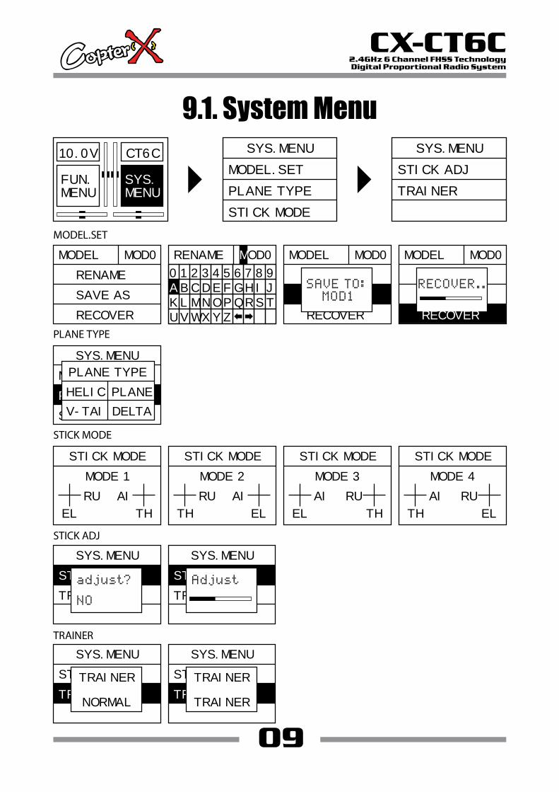
9.1. System Menu
09
CX-CT6C2.4GHz 6 Channel FHSS TechnologyDigital Proportional Radio System
10.0V CT6C
SYS.MENU
FUN.MENU
SYS.MENU
MODEL.SET
PLANE TYPE
STICK MODE
MODEL MOD0
RENAME
SAVE AS
RECOVER
MODEL MOD0
RENAME
RECOVER
SYS.MENU
STICK ADJ
TRAINER
MODEL.SET
PLANE TYPE
RENAME
0 1 2 3 4 5 6 7 8 9
B C D E F G H I J
K L M N O P Q R S T
U V W X Y Z
A
MOD0
SAVE AS
MODEL MOD0
RENAME
SAVE AS
SYS.MENU
MODEL.SET
STICK MODE
PLANE TYPE
PLANE TYPE
HELIC PLANE
V-TAI DELTA
STICK MODE
STICK ADJ
TRAINER
STICK MODE
MODE 1
RU AI
EL TH
STICK MODE
MODE 2
RU AI
TH EL
STICK MODE
MODE 3
AI RU
EL TH
STICK MODE
MODE 4
AI RU
TH EL
SYS.MENU
TRAINER
STICK ADJ
SYS.MENU
TRAINER
STICK ADJ
SYS.MENU
STICK ADJ
TRAINER
TRAINER
NORMAL
SYS.MENU
STICK ADJ
TRAINER
TRAINER
TRAINER
RECOVER
9.2. MODEL.SET
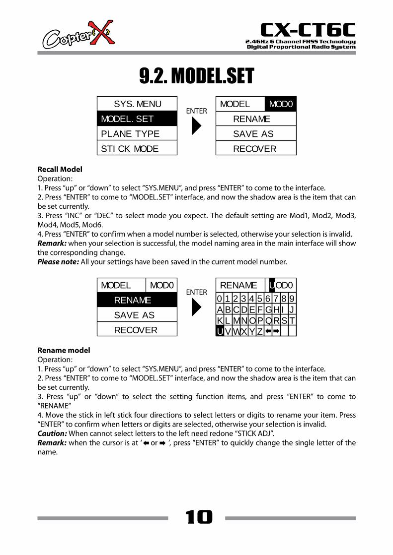
Recall ModelOperation:1. Press “up” or “down” to select “SYS.MENU”, and press “ENTER” to come to the interface.2. Press “ENTER” to come to “MODEL.SET” interface, and now the shadow area is the item that can be set currently.3. Press “INC” or “DEC” to select mode you expect. The default setting are Mod1, Mod2, Mod3, Mod4, Mod5, Mod6.4. Press “ENTER” to confirm when a model number is selected, otherwise your selection is invalid.Remark: when your selection is successful, the model naming area in the main interface will show the corresponding change.Please note: All your settings have been saved in the current model number.
Rename modelOperation:1. Press “up” or “down” to select “SYS.MENU”, and press “ENTER” to come to the interface.2. Press “ENTER” to come to “MODEL.SET” interface, and now the shadow area is the item that can be set currently.3. Press “up” or “down” to select the setting function items, and press “ENTER” to come to “RENAME”4. Move the stick in left stick four directions to select letters or digits to rename your item. Press “ENTER” to confirm when letters or digits are selected, otherwise your selection is invalid.Caution: When cannot select letters to the left need redone “STICK ADJ”.Remark: when the cursor is at ‘ or ’, press “ENTER” to quickly change the single letter of the name.
ENTER
10
CX-CT6C2.4GHz 6 Channel FHSS TechnologyDigital Proportional Radio System
SYS.MENU
PLANE TYPE
STICK MODE
MODEL.SET
MODEL
RENAME
SAVE AS
RECOVER
MOD0
ENTERMODEL
SAVE AS
RECOVER
MOD0
RENAME
RENAME
0 1 2 3 4 5 6 7 8 9
B C D E F G H I J
K L M N O P Q R S T
V W X Y Z
A
UOD0
U

11
CX-CT6C2.4GHz 6 Channel FHSS TechnologyDigital Proportional Radio System
Save as model numberOperation:1. Press “down“ to select “SYS.MENU”, and press “ENTER” to come to the interface.2. Press “ENTER” to come to “MODEL.SET” interface, and now the shadow area is the item that can be set currently.3. Press “up” or “down” to select the setting item, and press “ENTER” to come to “SAVE AS”4. Press “up” or “down” to select your model number to be saved. Press “ENTER” to confirm when the number is selected. It can be saved again and again in different model number groups. Press “EXIT” to leave the setting.Remark: the data of the current model will copy to another memory slot, so please be careful.
ENTERMODEL
RECOVER
MOD0
RENAME
SAVE AS
MODEL MOD0
RENAME
RECOVER
SAVE AS
Recover the factory dataOperation:1. Press “down” to select “SYS.MENU”, and press “ENTER” to come to the interface.2. Press “ENTER” to come to “MODEL.SET” interface, and now the shadow area is the item that can be set currently.3. Press “up” or “down” to select the setting item, and press “ENTER” to come to “RECOVER”4. Press “ENTER” to recover the factory setting, and press “EXIT” to leave the menu.Remark: This recovery will clear the data of the current model, please be careful.
ENTERMODEL MOD0
RENAME
SAVE AS
RECOVER
MODEL MOD0
RENAME
SAVE AS
RECOVER
9.3. PLANE TYPE
9.4. STICK MODE
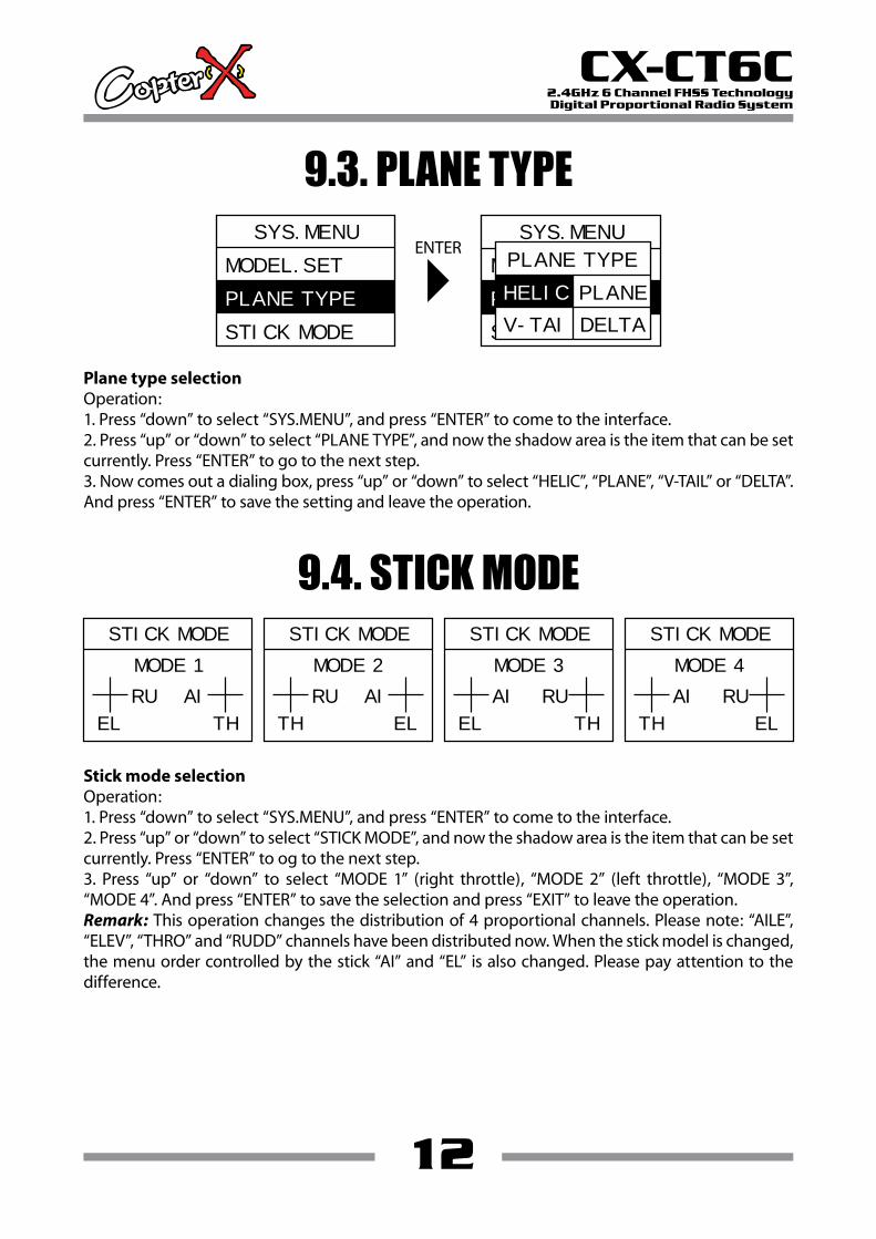
Plane type selectionOperation:1. Press “down” to select “SYS.MENU”, and press “ENTER” to come to the interface.2. Press “up” or “down” to select “PLANE TYPE”, and now the shadow area is the item that can be set currently. Press “ENTER” to go to the next step.3. Now comes out a dialing box, press “up” or “down” to select “HELIC”, “PLANE”, “V-TAIL” or “DELTA”. And press “ENTER” to save the setting and leave the operation.
Stick mode selectionOperation:1. Press “down” to select “SYS.MENU”, and press “ENTER” to come to the interface.2. Press “up” or “down” to select “STICK MODE”, and now the shadow area is the item that can be set currently. Press “ENTER” to og to the next step.3. Press “up” or “down” to select “MODE 1” (right throttle), “MODE 2” (left throttle), “MODE 3”, “MODE 4”. And press “ENTER” to save the selection and press “EXIT” to leave the operation.Remark: This operation changes the distribution of 4 proportional channels. Please note: “AILE”, “ELEV”, “THRO” and “RUDD” channels have been distributed now. When the stick model is changed, the menu order controlled by the stick “AI” and “EL” is also changed. Please pay attention to the difference.
ENTER
12
CX-CT6C2.4GHz 6 Channel FHSS TechnologyDigital Proportional Radio System
SYS.MENU
STICK MODE
MODEL.SET
PLANE TYPE
SYS.MENU
MODEL.SET
STICK MODE
PLANE TYPE
PLANE TYPE
PLANE
V-TAI DELTA
HELIC
STICK MODE
MODE 1
RU AI
EL TH
STICK MODE
MODE 2
RU AI
TH EL
STICK MODE
MODE 3
AI RU
EL TH
STICK MODE
MODE 4
AI RU
TH EL

9.5. STICK ADJ
Stick neutral position settingOperation:1. Press “ENTER” to come to “STICK ADJ” interface, and now the shadow area is the item that can be set currently.2. Before your operation, please be sure that the 4 proportional channels of the sticks are in the neutral position and the 4 electronic trim buttons are also in the neutral position.3. Press “ENTER” to enter, and now comes out a dialing box. Press “up” or “down” to select “NO” or “YES”, and press “ENTER”. When you hear one “beep” sound, the neutral setting is successful.4. Press “EXIT” to save and leave the setting.
ENTER
13
CX-CT6C2.4GHz 6 Channel FHSS TechnologyDigital Proportional Radio System
ENTERSYS.MENU
TRAINER
STICK ADJ
SYS.MENU
TRAINER
STICK ADJ
SYS.MENU
TRAINER
STICK ADJ
9.6. TRAINER
Trainer mode selectionOperation:1. Press “down” to select “SYS.MENU”, and press “ENTER” to come to the interface.2. Press “up” or “down” to select “NORMAL” or “TRAINER”.NORMAL: normal fly, TRAINER: simulator softwareNOTE1. This function is for simulator operation in the computer, optional simulator cable and software require.2. Please do not connect “Trainer” interface at the back of the transmitter to any electric equipment or other radio transmitters, or else, we are not responsible for any damages.3. This interface does not support training function, it is only for flying simulation software.
ENTERSYS.MENU
STICK ADJ
TRAINER
SYS.MENU
STICK ADJ
TRAINER
TRAINER
NORMAL
SYS.MENU
STICK ADJ
TRAINER
TRAINER
TRAINER
Simulating JACK
10.1. Function Menu (Heli.)
14
CX-CT6C2.4GHz 6 Channel FHSS TechnologyDigital Proportional Radio System
10.0V CT6C
SYS.MENU
FUN.MENU
FUN.MENU
D/R
SUB. TRIM
TRAVEL
FUN.MENU
CH.REV
SWASH.MIX
GYRO.SENE
FUN.MENU
THRO.CURV
MONITOR
PIT.CURV
FUN.MENU
THRO.HOLD
D/R
SUB. TRIM
TRAVEL
CH.REV
DR AILE0
H
I
O
L
0
0
100
100
DR ELEV0
H
I
O
L
0
0
100
100
DR RUDD0
H
I
O
L
0
0
100
100
SUB. TRIM
AILE
ELEV
THRO
0
0
0
TRAVEL
AILE
ELEV
THRO
100
100
100
100
100
100
REV.SW
CH
REV
NOR
TRAVEL
RUDD
GEAR
PITH
100
100
100
100
100
100
SUB. TRIM
RUDD
GEAR
PITH
0
0
0
1 2 3 4 5 6
15
CX-CT6C2.4GHz 6 Channel FHSS TechnologyDigital Proportional Radio System
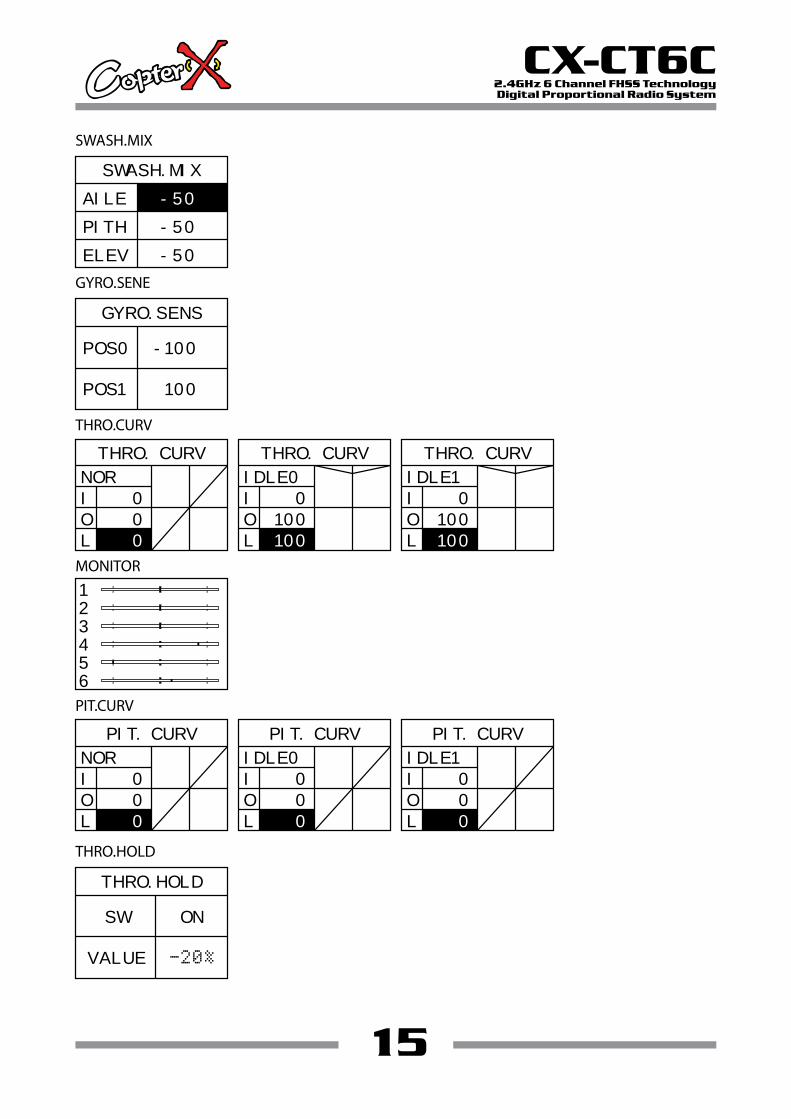
SWASH.MIX
GYRO.SENE
THRO.CURV
MONITOR
SWASH.MIX
AILE
PITH
ELEV
-50
-50
-50
1
2
3
4
5
6
GYRO.SENS
POS0
POS1 100
-100
THRO.HOLD
THRO.HOLD
SW
VALUE
ON
THRO. CURV
NOR
I
O
L
0
0
0
PIT.CURV
PIT. CURV
NOR
I
O
L
0
0
0
THRO. CURV
IDLE0
I
O
L
0
100
100
THRO. CURV
IDLE1
I
O
L
0
100
100
PIT. CURV
IDLE0
I
O
L
0
0
0
PIT. CURV
IDLE1
I
O
L
0
0
0
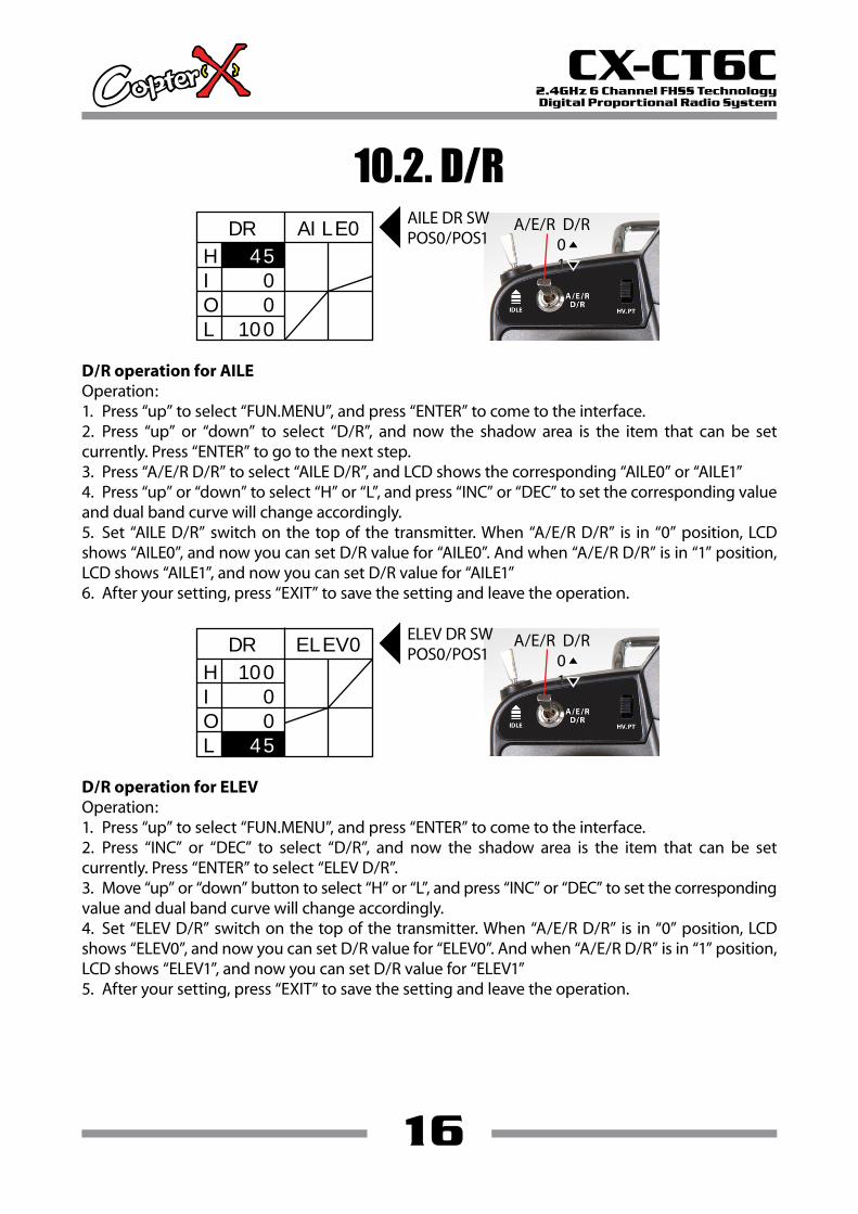
10.2. D/R
16
CX-CT6C2.4GHz 6 Channel FHSS TechnologyDigital Proportional Radio System
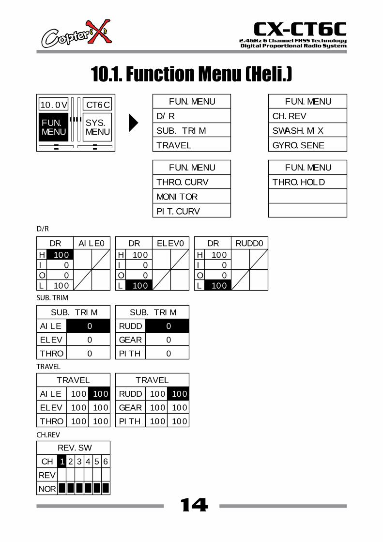
D/R operation for AILEOperation:1. Press “up” to select “FUN.MENU”, and press “ENTER” to come to the interface.2. Press “up” or “down” to select “D/R”, and now the shadow area is the item that can be set currently. Press “ENTER” to go to the next step.3. Press “A/E/R D/R” to select “AILE D/R”, and LCD shows the corresponding “AILE0” or “AILE1”4. Press “up” or “down” to select “H” or “L”, and press “INC” or “DEC” to set the corresponding value and dual band curve will change accordingly.5. Set “AILE D/R” switch on the top of the transmitter. When “A/E/R D/R” is in “0” position, LCD shows “AILE0”, and now you can set D/R value for “AILE0”. And when “A/E/R D/R” is in “1” position, LCD shows “AILE1”, and now you can set D/R value for “AILE1”6. After your setting, press “EXIT” to save the setting and leave the operation.
DR AILE0
H
I
O
L
0
0
100
45
A/E/R D/R0101
AILE DR SWPOS0/POS1
D/R operation for ELEVOperation:1. Press “up” to select “FUN.MENU”, and press “ENTER” to come to the interface.2. Press “INC” or “DEC” to select “D/R”, and now the shadow area is the item that can be set currently. Press “ENTER” to select “ELEV D/R”.3. Move “up” or “down” button to select “H” or “L”, and press “INC” or “DEC” to set the corresponding value and dual band curve will change accordingly.4. Set “ELEV D/R” switch on the top of the transmitter. When “A/E/R D/R” is in “0” position, LCD shows “ELEV0”, and now you can set D/R value for “ELEV0”. And when “A/E/R D/R” is in “1” position, LCD shows “ELEV1”, and now you can set D/R value for “ELEV1”5. After your setting, press “EXIT” to save the setting and leave the operation.
DR ELEV0
H
I
O
L
0
0
100
45
A/E/R D/R0101
ELEV DR SWPOS0/POS1
17
CX-CT6C2.4GHz 6 Channel FHSS TechnologyDigital Proportional Radio System
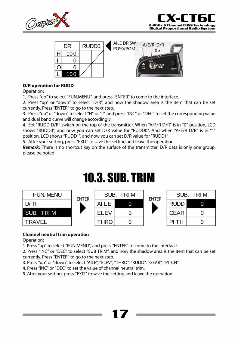
D/R operation for RUDDOperation:1. Press “up” to select “FUN.MENU”, and press “ENTER” to come to the interface.2. Press “up” or “down” to select “D/R”, and now the shadow area is the item that can be set currently. Press “ENTER” to go to the next step.3. Press “up” or “down” to select “H” or “L”, and press “INC” or “DEC” to set the corresponding value and dual band curve will change accordingly.4. Set “RUDD D/R” switch on the top of the transmitter. When “A/E/R D/R” is in “0” position, LCD shows “RUDD0”, and now you can set D/R value for “RUDD0”. And when “A/E/R D/R” is in “1” position, LCD shows “RUDD1”, and now you can set D/R value for “RUDD1”5. After your setting, press “EXIT” to save the setting and leave the operation.Remark: There is no shortcut key on the surface of the transmitter, D/R data is only one group, please be noted.
DR RUDD0
H
I
O
L
0
0
100
100
A/E/R D/R0101
AILE DR SWPOS0/POS1
10.3. SUB. TRIM
Channel neutral trim operationOperation:1. Press “up” to select “FUN.MENU”, and press “ENTER” to come to the interface.2. Press “INC” or “DEC” to select “SUB TRIM”, and now the shadow area is the item that can be set currently. Press “ENTER” to go to the next step.3. Press “up” or “down” to select “AILE”, “ELEV”, “THRO”, “RUDD”, “GEAR”, “PITCH”.4. Press “INC” or “DEC” to set the value of channel neutral trim.5. After your setting, press “EXIT” to save the setting and leave the operation.
ENTER ENTERFUN.MENU
TRAVEL
D/R
SUB. TRIM
SUB. TRIM
AILE
ELEV
THRO
0
0
0
SUB. TRIM
RUDD
GEAR
PITH
0
0
0
18
CX-CT6C2.4GHz 6 Channel FHSS TechnologyDigital Proportional Radio System
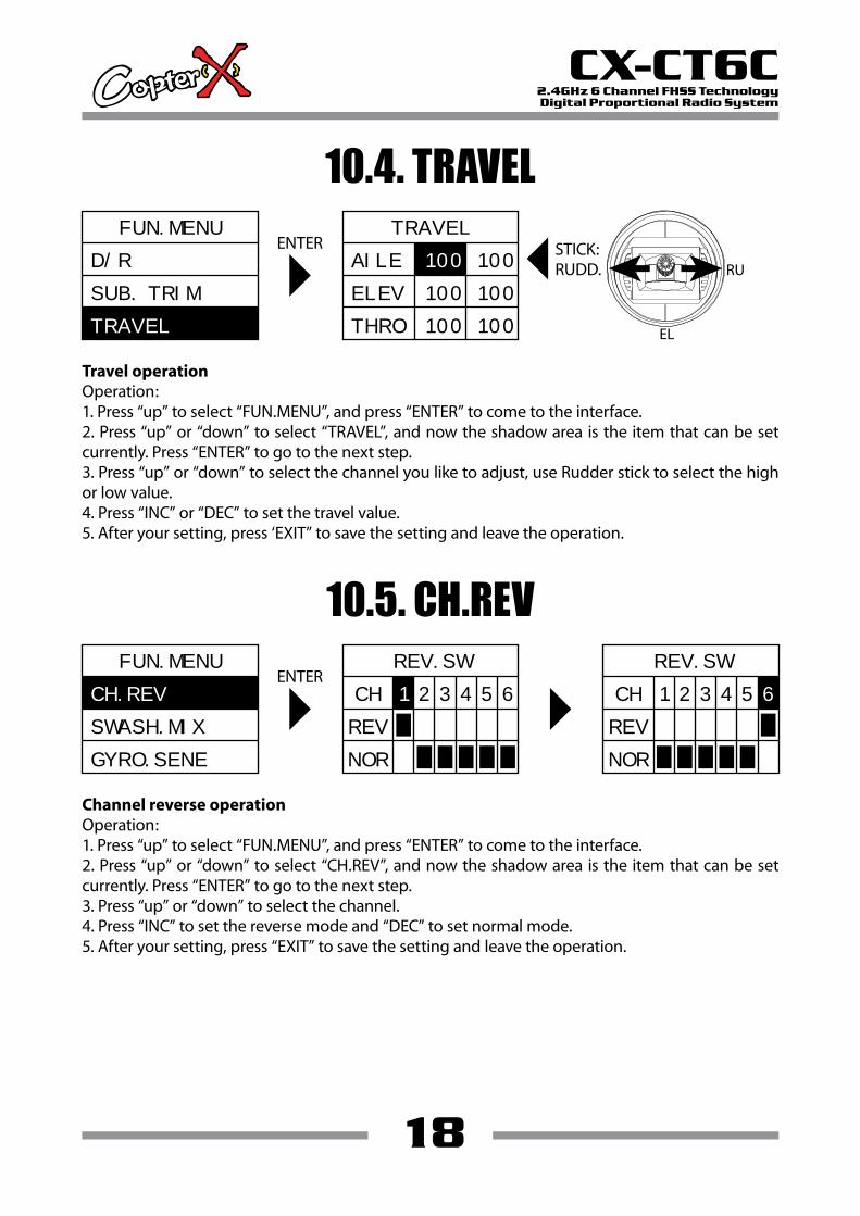
10.4. TRAVEL
Travel operationOperation:1. Press “up” to select “FUN.MENU”, and press “ENTER” to come to the interface.2. Press “up” or “down” to select “TRAVEL”, and now the shadow area is the item that can be set currently. Press “ENTER” to go to the next step.3. Press “up” or “down” to select the channel you like to adjust, use Rudder stick to select the high or low value.4. Press “INC” or “DEC” to set the travel value.5. After your setting, press ‘EXIT” to save the setting and leave the operation.
ENTERFUN.MENU
D/R
SUB. TRIM
TRAVEL
TRAVEL
AILE
ELEV
THRO
100
100
100
100
100
100STICK:RUDD. RU
EL
10.5. CH.REV
Channel reverse operationOperation:1. Press “up” to select “FUN.MENU”, and press “ENTER” to come to the interface.2. Press “up” or “down” to select “CH.REV”, and now the shadow area is the item that can be set currently. Press “ENTER” to go to the next step.3. Press “up” or “down” to select the channel.4. Press “INC” to set the reverse mode and “DEC” to set normal mode.5. After your setting, press “EXIT” to save the setting and leave the operation.
ENTERFUN.MENU
SWASH.MIX
GYRO.SENE
REV.SW
CH
REV
NOR
1 2 3 4 5 6
REV.SW
CH
REV
NOR
1 2 3 4 5 6CH.REV
19
CX-CT6C2.4GHz 6 Channel FHSS TechnologyDigital Proportional Radio System
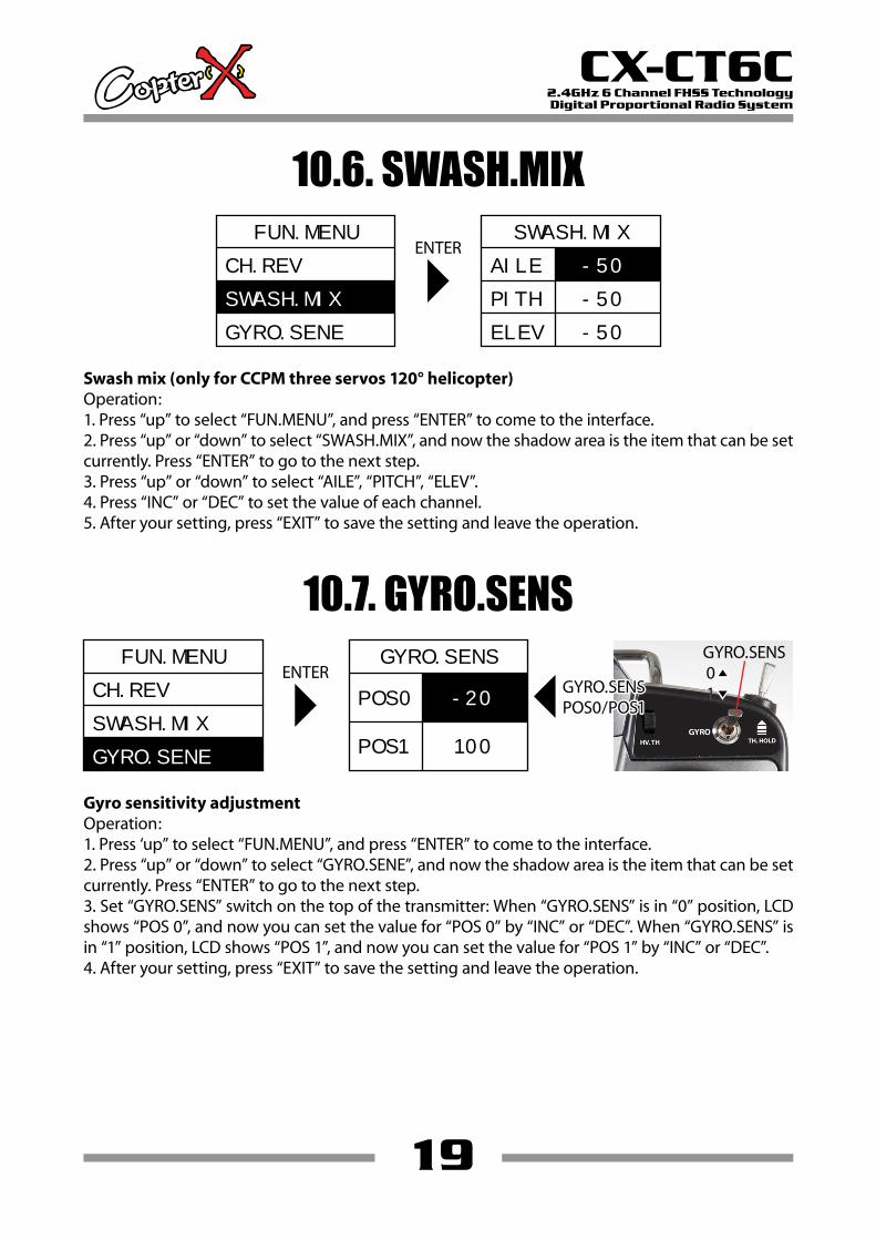
10.6. SWASH.MIX
Swash mix (only for CCPM three servos 120° helicopter)Operation:1. Press “up” to select “FUN.MENU”, and press “ENTER” to come to the interface.2. Press “up” or “down” to select “SWASH.MIX”, and now the shadow area is the item that can be set currently. Press “ENTER” to go to the next step.3. Press “up” or “down” to select “AILE”, “PITCH”, “ELEV”.4. Press “INC” or “DEC” to set the value of each channel.5. After your setting, press “EXIT” to save the setting and leave the operation.
ENTERFUN.MENU
SWASH.MIX
GYRO.SENE
CH.REV
FUN.MENU
SWASH.MIX
GYRO.SENE
CH.REV
SWASH.MIX
AILE
PITH
ELEV
-50
-50
-50
10.7. GYRO.SENS
Gyro sensitivity adjustmentOperation:1. Press ‘up” to select “FUN.MENU”, and press “ENTER” to come to the interface.2. Press “up” or “down” to select “GYRO.SENE”, and now the shadow area is the item that can be set currently. Press “ENTER” to go to the next step.3. Set “GYRO.SENS” switch on the top of the transmitter: When “GYRO.SENS” is in “0” position, LCD shows “POS 0”, and now you can set the value for “POS 0” by “INC” or “DEC”. When “GYRO.SENS” is in “1” position, LCD shows “POS 1”, and now you can set the value for “POS 1” by “INC” or “DEC”.4. After your setting, press “EXIT” to save the setting and leave the operation.
ENTERGYRO.SENS0101GYRO.SENSGYRO.SENS
POS0/POS1POS0/POS1GYRO.SENSPOS0/POS1
GYRO.SENS
POS0
POS1 100
-20

20
CX-CT6C2.4GHz 6 Channel FHSS TechnologyDigital Proportional Radio System
IDLE SW
10.8. THRO.CURV
Throttle curve operationOperation:1. Press “up” to select “FUN.MENU”, and press “ENTER” to come to the interface.2. Press “up” or “down” to select “THRO.CURV”, and now the shadow area is the item that can be set currently. Press “ENTER” to go to the next step.3. There are three throttle curves to be selected, normal, IDLE 0 and IDLE 1 by the switch at the left top of the transmitter.4. Press “up” or “down” to select the throttle curve point. There are 5 points, they are L, 1, 2, 3, H. Press “INC” or “DEC” to set the corresponding value separately, and the throttle curve will change accordingly.5. After you setting, press “EXIT” to save the setting and leave the operation.Remark: the transmitter can save 3 groups of different throttle curves.
IDLE SWIDLE SWOFF/POS0/POS1OFF/POS0/POS1
IDLE SWOFF/POS0/POS1
OFFOFF01
OFF01
THRO. CURV
NOR
I
O
L
0
0
0
THRO. CURV
IDLE1
I
O
H
20
80
100
10.9. MONITOR
Monitor systemOperation:1. Press “up” to select “FUN.MENU”, and press “ENTER” to come to the interface.2. Press “up” or “down” to select “MONITOR”, and now the shadow area is the item that can be set currently. Press “ENTER” to go to the next step.3. When you move the sticks or channel switches, you can find the corresponding channel bars will change accordingly. This function is designed to monitor the working conditions of the transmitter.4. After your setting, press “EXIT” to save the setting and leave the operation.Remark: This function helps you adjust the setting, neutral trim as well as channel inspection.
ENTERFUN.MENU
MONITOR
PIT. CURV
THRO. CURV
1
2
3
4
5
6
21
CX-CT6C2.4GHz 6 Channel FHSS TechnologyDigital Proportional Radio System
IDLE SW
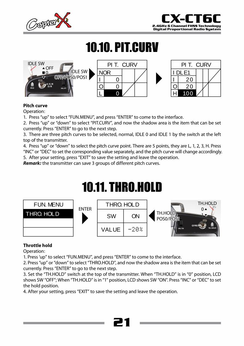
10.10. PIT.CURV
Pitch curveOperation:1. Press “up” to select “FUN.MENU”, and press “ENTER” to come to the interface.2. Press “up” or “down” to select “PIT.CURV”, and now the shadow area is the item that can be set currently. Press “ENTER” to go to the next step.3. There are three pitch curves to be selected, normal, IDLE 0 and IDLE 1 by the switch at the left top of the transmitter.4. Press “up” or “down” to select the pitch curve point. There are 5 points, they are L, 1, 2, 3, H. Press “INC” or “DEC” to set the corresponding value separately, and the pitch curve will change accordingly.5. After your setting, press “EXIT” to save the setting and leave the operation.Remark: the transmitter can save 3 groups of different pitch curves.
IDLE SWIDLE SWOFF/POS0/POS1OFF/POS0/POS1
IDLE SWOFF/POS0/POS1
OFFOFF01
OFF01
PIT. CURV
NOR
I
O
L
0
0
0
PIT. CURV
IDLE1
I
O
H
20
20
100
10.11. THRO.HOLD
Throttle holdOperation:1. Press ‘up” to select “FUN.MENU”, and press “ENTER” to come to the interface.2. Press “up” or “down” to select “THRO.HOLD”, and now the shadow area is the item that can be set currently. Press “ENTER” to go to the next step.3. Set the “TH.HOLD” switch at the top of the transmitter. When “TH.HOLD” is in “0” position, LCD shows SW “OFF”; When “TH.HOLD” is in “1” position, LCD shows SW “ON”. Press “INC” or “DEC” to set the hold position.4. After your setting, press “EXIT” to save the setting and leave the operation.
ENTERFUN.MENU
THRO.HOLD
TH.HOLD0101TH.HOLDTH.HOLD
POS0/POS1POS0/POS1TH.HOLDPOS0/POS1
THRO.HOLD
SW
VALUE
ON
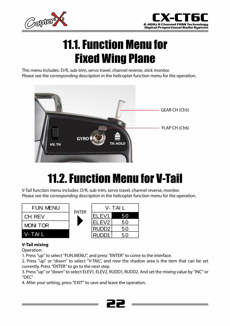
This menu includes: D/R, sub-trim, servo travel, channel reverse, stick monitor.Please see the corresponding description in the helicopter function menu for the operation.
22
CX-CT6C2.4GHz 6 Channel FHSS TechnologyDigital Proportional Radio System
11.1. Function Menu forFixed Wing Plane
GEAR CH (Ch5)
FLAP CH (Ch6)
11.2. Function Menu for V-TailV-Tail function menu includes: D/R, sub-trim, servo travel, channel reverse, monitor. Please see the corresponding description in the helicopter function menu for the operation.
ENTERFUN.MENU
MONITOR
V-TAIL
CH.REV
V-TAIL
ELEV1
ELEV2 50
RUDD2 50
RUDD1 50
V-Tail mixingOperation:1. Press “up” to select “FUN.MENU”, and press “ENTER” to come to the interface.2. Press “up” or “down” to select “V-TAIL”, and now the shadow area is the item that can be set currently. Press “ENTER” to go to the next step.3. Press “up” or “down” to select ELEV1, ELEV2, RUDD1, RUDD2. And set the mixing value by “INC” or “DEC”4. After your setting, press “EXIT” to save and leave the operation.
50
23
CX-CT6C2.4GHz 6 Channel FHSS TechnologyDigital Proportional Radio System
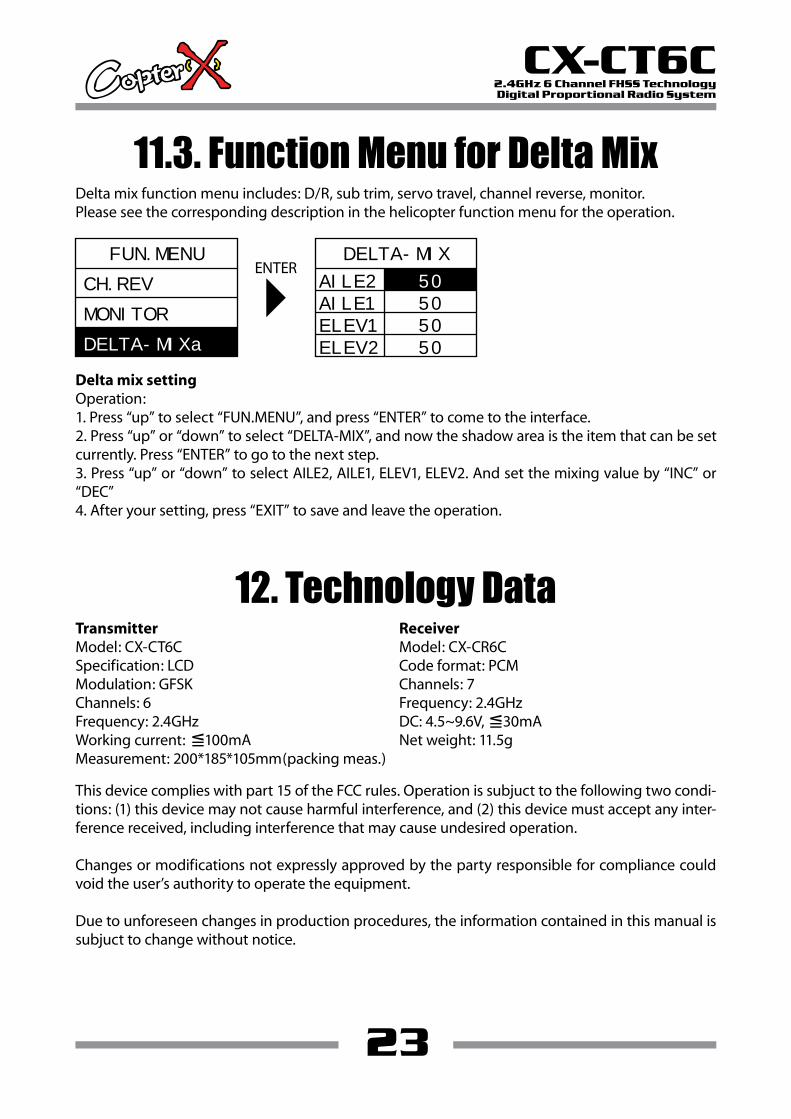
11.3. Function Menu for Delta MixDelta mix function menu includes: D/R, sub trim, servo travel, channel reverse, monitor. Please see the corresponding description in the helicopter function menu for the operation.
12. Technology Data
ENTERFUN.MENU
MONITOR
DELTA-MIXa
CH.REV
DELTA-MIX
AILE2
AILE1 50
ELEV1 50
ELEV2 50
Delta mix settingOperation:1. Press “up” to select “FUN.MENU”, and press “ENTER” to come to the interface.2. Press “up” or “down” to select “DELTA-MIX”, and now the shadow area is the item that can be set currently. Press “ENTER” to go to the next step.3. Press “up” or “down” to select AILE2, AILE1, ELEV1, ELEV2. And set the mixing value by “INC” or “DEC”4. After your setting, press “EXIT” to save and leave the operation.
This device complies with part 15 of the FCC rules. Operation is subjuct to the following two condi-tions: (1) this device may not cause harmful interference, and (2) this device must accept any inter-ference received, including interference that may cause undesired operation.
Changes or modifications not expressly approved by the party responsible for compliance could void the user’s authority to operate the equipment.
Due to unforeseen changes in production procedures, the information contained in this manual is subjuct to change without notice.
TransmitterModel: CX-CT6CSpecification: LCDModulation: GFSKChannels: 6Frequency: 2.4GHzWorking current: ≦100mAMeasurement: 200*185*105mm(packing meas.)
ReceiverModel: CX-CR6CCode format: PCMChannels: 7Frequency: 2.4GHzDC: 4.5~9.6V, ≦30mANet weight: 11.5g
50

www.copterx.comCopyright © 2011 KY MODEL Company Limited.