Embed Size (px)
Citation preview

Radio Transmitters 2011
Radio Transmitters
1. INTRODUCTION
The fundamental equipment used for radio communication are the transmitter and receiver.
The transmitter must generate a radio frequency signal of sufficient power at the desired
frequency. It must have some means of varying (or modulating) the carrier frequency so that it
can carry an intelligible signal.
The receiver must select the desired frequency you want to receive and reject all unwanted
frequencies. In addition, receivers must be able to amplify the weak incoming signal to
overcome the losses the signal suffers during transmission.
Fig 1: Radio transmission block diagram

Radio Transmitters 2011
Table 1: Radio frequency Spectrum
TRANSMITTER CLASSIFICATION
Radio transmitter may be classified into following categories
• According to the type of modulation used
• According to the service involved
• According to the frequency range involved.

Radio Transmitters 2011
CLASSIFICATION ACCORDING TO THE TYPE OF MODULATION
i) Amplitude Modulation Transmitters:
In A.M transmitter, the modulating signal amplitude modulates the carrier. Such transmitters
are used for radio broadcast on long, medium and short eaves, radio telephony on short waves,
radio telegraphy on short waves, television picture broadcast on every short waves or ultra short
waves.
ii) Frequency Modulation transmitters:
In an FM transmitter, the signal voltage frequency modulates the carrier. Such transmitters are
used for broadcast in V.H.F and U.H.F range, television sound broadcast in V.H.F and U.H.F
ranges, radio telephony communication in V.H.F and U.H.F range over short distances
iii) Pulse Modulation Transmitter: In a pulse modulation transmitter, the signal voltage alters
some characteristic of the pulses. Theses characteristics of the pulse altered on modulation may
be pulse width, pulse position, pulse amplitude, pulse frequency or pulse code.
CLASSIFICATION ACCORDING TO THE TYPE OF SERVICE
(i)Radio Broadcast Transmitters:
Theses transmitters are designed for transmitting speech, music etc for the information and
reception of people. These broadcast transmitters may be either amplitude modulated or
frequency modulated. The A.M transmitters operate on long waves, medium waves and short
waves
The F.M broadcast transmitters operate on very short waves or on ultra waves .
ii) Radio Telephony Transmitters:
These transmitters are designed for transmitting telephone signals over long distance by radio
means. A radio telephone transmitter uses certain special as volume compressors, privacy
devices, peak limiters etc. Radio telephone transmitters may be either of amplitude modulation
type or frequency modulation type.
iii) Radio Telegraph Transmitters:
A radio telegraph transmitter transmits telegraph signals from one radio station to another
radio station. It may use either amplitude modulation or frequency modulation. When point to-

Radio Transmitters 2011
point radio communication is involved, the transmitting antennas are highly directive so that the
electromagnetic energy is beamed into a narrow beam directed towards the receiving antenna
at the receiving radio station.
iv)Television transmitters:
Television broadcast requires two transmitters one for transmission of picture and other for
transmission of sound. Both operate in very high frequency or ultra high frequency range. The
picture transmitter is amplitude modulated by the picture signal occupying a band about 75
MHz. The total bandwidth occupied by one television channel is about 7 MHz.
v) Radar Transmitters:
Radar may be Pulse radar or Continuous Wave radar.
Pulse radar transmitter uses pulse modulation of carrier operates at microwave frequencies
typically 3000 MHz or 10,000 MHz.
Continuous Wave radar transmitter uses frequency modulation of the carrier voltage or may
utilize Doppler Effect.
CLASSIFICATION OF RADIO TRANSMITTERS ACCORDING TO THE CARRIER FREQUENCY
In this classification, transmitters may be classified as below
(i) Long Wave Transmitters:
These transmitters operate on long waves . Long wave radio signals travel along the surface of
earth and are rapidly attenuated, for reasonably high signal strength at the distant receiving
aerial, the carrier power radiated from the transmitting aerial must be large.
(ii) Medium Wave Transmitters:
These transmitters operate on frequencies in the Broadcast band ranging from 550 to 1650 kHz
(iii)Short Wave Transmitters:
These transmitters operate on frequencies in the short wave range of 3 to 30MHz. The
attenuation of radio waves travelling from the transmitting aerial to the distant receiving aerial
though the ionosphere is small

Radio Transmitters 2011
2. AMPLITUDE MODULATED TRANSMITTERS
Amplitude modulation process is completed in two stages, one is modulation which is
performed at the transmitters and other is demodulation which is done at receiver.
A transmitter not only performs the modulation process, but also raises the power level of a
modulated signal to the desired extent for effective radiation.
In AM transmitters, the instantaneous amplitude of the rf(radio frequency) output signal is
varied in proportion to the modulating signal. The modulating signal may consist of many
frequencies of various amplitudes and phases.
AM transmitters can be broadly divided into two categories:-
(i) Low level modulation: The block diagram for this type of transmitter is shown in figure 2
(ii) High level modulation: The block diagram for this type of transmitter is shown in figure 3
High level modulation
In this type of AM modulation, modulation takes place at the final power amplifier stage of the
transmitter, just before it is transmitted by the antenna.
This is done to avoid taking the modulated composite signal through non linear devices because
this generates new frequencies, which would have the effect of introducing audible distortion
into the modulated signal.
The disadvantage of AM-modulating the final amplifier stage is that doing so requires audio
power equal to 50% of the carrier power. Thus for a 10 KW transmitter, the audio power
amplifier of 5kW would be required.

Radio Transmitters 2011
Fig 2.1: High level modulation AM transmitter.
Low level modulation
Low level modulation means modulation applied to a low-power stage before the power
amplifier boosts it to the full transmit power level. That's obviously a great benefit, because you
don't need nearly as much audio power, so the audio stages are much less expensive.
But also this means that every stage after modulation must be a highly linear stage, in order to
avoid distortion. Thus the power amplifier must be class A instead of Class-C final power
amplifier.
Class-A means much lower efficiency, so it has to be bigger, and use more DC power supply than
the Class-C, in order to send the same power up to the antenna.

Radio Transmitters 2011
Fig 2.2: Low level modulation AM transmitter
STAGES OF THE AMPLITUDE MODULATED TRANSMITTER
Master oscillator
The master oscillator generates a stable sub harmonic carrier frequency (i.e. the fraction of a
desired carrier frequency). This stable sub-harmonic oscillation is generated by using a crystal
oscillator which is an electronic oscillator circuit that uses the mechanical resonance of a
vibrating crystal of piezoelectric material to create an electrical signal with a very precise
frequency. The frequency is then raised to the desired value by harmonic generator.
Buffer amplifier
This is a tuned amplifier providing high input impedance at the master oscillator frequency. Any
variation in load current does not affect the master oscillator due to this high input impedance
of buffer amplifier at the operating frequency of the master oscillator.

Radio Transmitters 2011
Harmonic generator
This is an electronic circuit that generates harmonics of its input frequency by applying the signal
to a non-linear circuit, to generate harmonics of input frequency.
The desired harmonic is selected by a properly tuned circuit. The circuit uses a class C tuned
amplifier.
Driver Amplifier.
One or more stages of a class C tuned amplifier are used to increase the power level of a carrier
signal to provide a large drive to the modulated class C amplifier
Modulation stage
The collector modulation circuit is used for modulation in high power transmitters. The
modulating amplifier is a class A, or class B amplifier amplifying the base-band signal.
In figure 2.2.1, the rf carrier is applied to the base of modulator Q1. The modulating signal is
applied to the collector in series with the collector supply voltage through T3. The output is
then taken from the secondary of T2. With no modulating signal, Q1 acts as an rf amplifier for
the carrier frequency. When the modulation signal is applied, it adds to or subtracts from the
collector supply voltage. This causes the rf current pulses of the collector to vary in amplitude
with the collector supply voltage. These collector current pulses cause oscillations in the tank
circuit (C4 and the primary of T2). The tank circuit is tuned to the carrier frequency. During
periods when the collector current is high, the tank circuit oscillates strongly. At times when the
collector current is small or entirely absent, little or no energy is supplied to the tank and
oscillations become weak or die out. Thus, the modulation envelope is developed.

Radio Transmitters 2011
Fig 2.2.1: Collector modulation circuit
Feeder and antenna
The transmitter power is fed to a transmitting antenna for effective radiation. The length of the
antenna (a conductor) should be of the order of the wavelength for effective radiation.

Radio Transmitters 2011
SINGLE-SIDEBAND TRANSMITTER (SSB)
A carrier that has been modulated by voice or music is accompanied by two identical sidebands,
each carrying the same intelligence. In the conventional amplitude-modulated (AM)
transmitters, the carrier and both sidebands are transmitted. In a single-sideband transmitter
(SSB), only one of the sidebands, the upper or the lower, is transmitted while the remaining
sideband and the carrier are suppressed. Suppression is the elimination of the undesired
portions of the signal.
Figure 2.3 is the block diagram of a single-sideband transmitter. It is seen that the audio
amplifier increases the amplitude of the incoming signal to a level adequate to operate the SSB
generator. Usually the audio amplifier is just a voltage amplifier.
The SSB generator (modulator) combines its audio input and its carrier input to produce the
two sidebands. The two sidebands are then fed to a filter that selects the desired sideband and
suppresses the other one.
By eliminating the carrier and one of the sidebands, intelligence is transmitted at a savings in
power and frequency bandwidth.
In most cases SSB generators operate at very low frequencies when compared with the
normally transmitted frequencies. For that reason, we must convert (or translate) the filter
output to the desired frequency. This is the purpose of the mixer stage. A second output is
obtained from the frequency generator and fed to a frequency multiplier to obtain a higher
carrier frequency for the mixer stage. The output from the mixer is fed to a linear power
amplifier to build up the level of the signal for transmission.
Radio Transmitters 2011
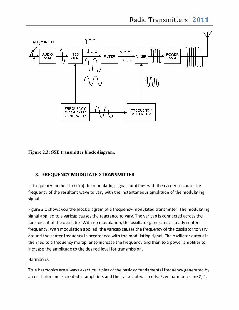
Figure 2.3: SSB transmitter block diagram.
3. FREQUENCY MODULATED TRANSMITTER
In frequency modulation (fm) the modulating signal combines with the carrier to cause the
frequency of the resultant wave to vary with the instantaneous amplitude of the modulating
signal.
Figure 3.1 shows you the block diagram of a frequency-modulated transmitter. The modulating
signal applied to a varicap causes the reactance to vary. The varicap is connected across the
tank circuit of the oscillator. With no modulation, the oscillator generates a steady center
frequency. With modulation applied, the varicap causes the frequency of the oscillator to vary
around the center frequency in accordance with the modulating signal. The oscillator output is
then fed to a frequency multiplier to increase the frequency and then to a power amplifier to
increase the amplitude to the desired level for transmission.
Harmonics
True harmonics are always exact multiples of the basic or fundamental frequency generated by
an oscillator and is created in amplifiers and their associated circuits. Even harmonics are 2, 4,

Radio Transmitters 2011
6, and so on, times the fundamental; odd harmonics are 3, 5, 7, and so on, times the
fundamental.
The series ascends indefinitely until the intensity is too weak to be detected. In general, the
energy in frequencies above the third harmonic is too weak to be significant.
Fig 3.1: Simplified Fm transmitter block diagram.
Frequency Multiplication
It is easier to design and build low frequency crystal oscillators. In some cases the crystal
oscillator operates at frequencies as low as 1/100 of the desired output frequency.
The oscillator frequency is raised to the required output frequency by passing it through one or
more frequency multipliers. Frequency multipliers are special power amplifiers that multiply
the input frequency. Stages that multiply the frequency by 2 are called doublers; those that
multiply by 3 are triplers; and those multiplying by 4 are quadruplers.
You will find the main difference between low-frequency and high-frequency transmitters is the
number of frequency-multiplying stages used.
Figure 3.2 shows the block diagram of the frequency-multiplying stages of a typical uhf/vhf
transmitter. The oscillator in this transmitter is tunable from 18 megahertz to 32 megahertz.
Radio Transmitters 2011
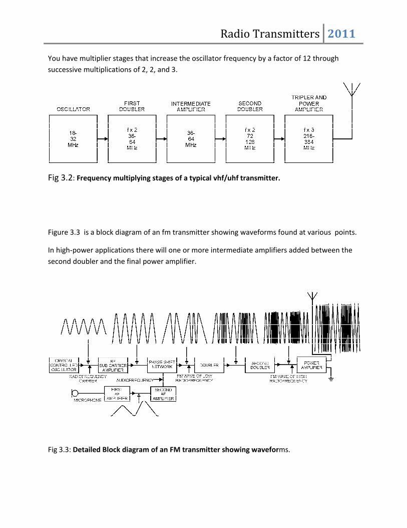
You have multiplier stages that increase the oscillator frequency by a factor of 12 through
successive multiplications of 2, 2, and 3.
Fig 3.2: Frequency multiplying stages of a typical vhf/uhf transmitter.
Figure 3.3 is a block diagram of an fm transmitter showing waveforms found at various points.
In high-power applications there will one or more intermediate amplifiers added between the
second doubler and the final power amplifier.
Fig 3.3: Detailed Block diagram of an FM transmitter showing waveforms.