Embed Size (px)
Citation preview

Radiosity A method for computing global illumination
Donald P. Greenberg, Michael F. Cohen, and Kenneth E. Torrance
Cornell University, Program of Computer Graphics, 120 Rand Hall, Ithaca, NY 14853, USA
The radiosity method for computing the interreflection of light within diffuse envi- ronments is described. The development of the method for realistic image synthesis over the past three years is outlined. A short discussion of the underlying theory and implementation is followed by a real life example which illustrates the power and accuracy of the radiosity method and points out the different results from ray tracing procedures. Current and future de- velopments of the radiosity method are outlined.
Key words: Radiosity - Reflectance mod- els - Interreflection - Diffuse
he following brief article reviews the radio- sity approach and explains the fundamen- tal algorithms used to generate images of diffuse environments. The work is not new,
but may help to clarify the difference between ray- tracing and radiosity in attempting to simulate global illumination effects. Light reflecting off of a surface depends upon the reflecting surface's properties (reflective, trans- missive, and absorptive) and the composition and direction of the incident light. In computer graph-
ics, the reflected light historically has been artifi- cially subdivided into three categories, ambient, diffuse, and specular reflections. Early models made no attempt to simulate the in- terreflections from object to object or the shadow- ing within an environment, and modeled the ambi- ent light as a constant term (Phong 1973). This approach resulted in images which were obviously computer generated, since the global illumination effects, resulting from the interreflections and sha- dowing, have significant effect on the lighting of a scene. In 1979, Whitted (1980) presented his classic paper on ray-tracing, producing images of excellent quali- ty. The method produced the most realistic pictures to data, creating enormous interest in the tech- nique. However, the ray-tracing procedure is lim- ited and can only model intra-environment reflec- tions in the specular direction. In addition, since lights are modeled as points in space, the shadows cast always exhibit sharp boundaries. Although improvements in sampling procedures, as well as more comprehensive reflection models have been made, the basic restrictions still exist (Hall 1986). Furthermore, the ray-tracing procedures are view- dependent, and the entire process must be repeated for every different view. By contrast, the radiosity method determines the global illumination of the environment indepen- dent of the viewer position. At the SIGGRAPH convention of 1984, Goral et al. (1984) first introduced this new approach to computer graphics. The new procedure, derived from methods used in thermal engineering, has a fundamental energy equilibrium basis, and correct- ly models the interaction of light between reflecting surfaces (Sparrow and Cess 1978). Goral's paper was restricted to simple, convex envi- ronments consisting only of diffusely reflecting sur- faces. However, the procedure demonstrated the significance of this approach by accurately simulat- ing the effects of diffuse area light sources as well as the "color bleeding" effects which are caused by diffuse reflections.
,4 The Visual Computer (1986) 2:291-297 L ~ | �9 Springer-Verlag 1986

The following year, two papers were presented which extended the radiosity method to occluded environments containing hidden surfaces and shad- ows. Cohen (1985) introduced a general procedure, the "hemi-cube", for computing the relationship be- tween discrete surfaces within occluded environ- ments. The "hemi-cube" technique was an efficient algorithm, similar in nature to the projection of visible surfaces, and was applicable to scenes of any complexity. Nishita and Nakamae (1985) also presented a paper which extended the radiosity method to complex environments. Shadows and occlusion ef- fects were computed by using a shadow algorithm restricted to convex polyhedra. In both presentations, because light sources were modeled as finite areas, subtle shadowing effects such as penumbrae were obtained, significantly im- proving the quality of the images. In addition, the previously arbitrary ambient term was replaced by an accurate representation of the global illumina- tion which arises from complex intra-environment reflections. To provide an explanation of the radiosity proce- dure, the following section describes the fundamen- tal algorithms.
Radiosity
Theory The radiosity method describes an equilibrium en- ergy balance within an enclosure. The essential fea- tures are presented below. It is assumed that all emission and reflection processes are ideally dif- fuse. The light leaving a surface (its radiosity) consists of self-emitted light and reflected or transmitted incident light. The amount of light arriving at a surface requires a complete specification of the geo- metric relationships among all reflecting and trans- mitting surfaces, as well as the light leaving every other surface. This relationship is given by:
N Bi=Ei+pi ~, B3F q for i = l t o N (1)
j = l
Radiosity (B): The total rate of energy leaving a surface. Sum of emitted and reflected energy. (energy/unit time time/unit area)
Emission (E): The rate of energy (light) emitted from a surface. (energy/unit time/unit area) Reflectivity (p): The fraction of incident light which is reflected back into the environment. (unitless) Form-factor (F): The fraction of the energy leaving one surface which lands on another surface. (unit- less) N = the number of discrete surfaces of "patches".
This equation states that the amount of energy (or light) leaving a particular surface is equal to the self-emitted light plus the reflected light. The re- flected light is equal to the light leaving every other surface multiplied by both the fraction of that light which reaches the surface in question, and the re- flectivity of the receiving surface. The sum of the reflected light from a given surface plus the light emitted directly from the surface is termed its ra- diosity (Fig. 1). If the environment is subdivided into discrete sur- face entities called "patches", for which a constant radiosity is assumed, a set of simultaneous equa- tions can be generated to describe the interaction of light energy within the environment. These equations take the form:
I 1 - - P l Ftl - - P l F12 ..-
--P2 F21 l - -p2 F22 ..- !
--PN FN1
--P2F2N] = 1--pN:FNNJ B
(2)
Since the color of an object is determined by its reflectivity or emissivity at each wavelength of the visible spectrum, the reflectivity and emission terms in the above equations are valid for a particular wavelength or band of wavelengths. It is necessary to form and solve the above matrix for each band of interest in order to determine the full radiosity
E i (~,io~) ) ~i ( radiosity )
~ per tt~t &re~ )
Fig. 1. Total radiosity
292
5employer of each patch. It is important to note that the form- factors are solely a function of geometry and are thus independent of any color considerations.
The form-factor
The form-factor specifies the fraction of the energy leaving one surface which lands on another. By definition the sum of all the form-factors from a particular point or patch is equal to unity. The form-factor between finite surfaces (patches) i s :
T1 j. j, cos c~ Cj dAj clA (3) f i J ~ ' * i A~ Aj
The geometric terms in the form-factor derivation are illustrated in Fig. 2. A geometric analog for the form-factor integral was developed by Nusselt (Sparrow and Cess 1978) and has been used to obtain form-factors by both pho- tography and planimetry (Fig. 3). For a finite area, the form-factor is equivalent to the fraction of the circle (which is the base of the hemisphere) covered by projecting the area onto the hemisphere and then orthographically down onto. the circle. In Equation (3), the expression for the form-factor does not account for the possibility of occluding objects hiding all or part of one patch from an- other. There is, therefore, a missing term within the integrand if hidden surfaces are to be accounted f o r .
1 ~ ~ cos q5 i cos Cj HIDij dAj dA~ (4) f iJ-=Aii al a i ~ r2
The HID function has the effect of producing the projection of area j visible from differential area i. It is the solution for this double area integral
n~ @/~ Fig. 2. Form-fac tor geometry
Fig. 3. Nusselt analog. The form-factor is equal to the fraction of the base of hemisphere covered by the project ion
(4), which must be found to solve for radiosities in any non-convex environment.
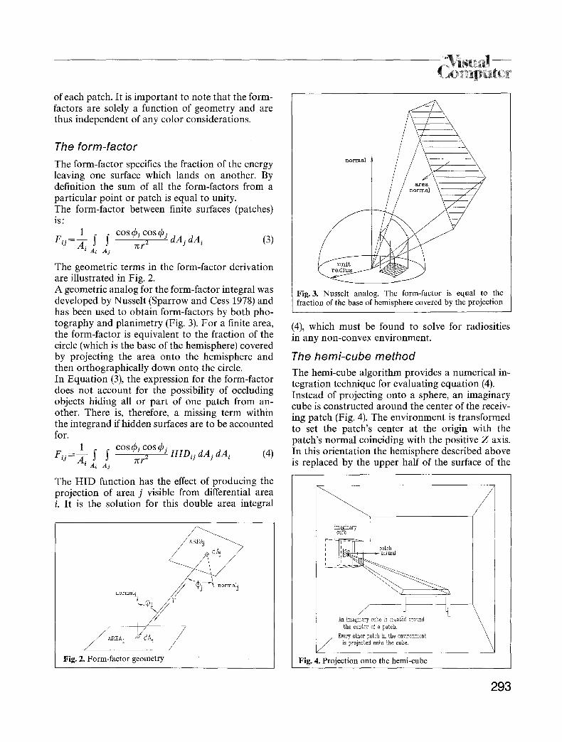
The hemi-cube method
The hemi-cube algorithm provides a numerical in- tegration technique for evaluating equation (4). Instead of projecting onto a sphere, an imaginary cube is constructed around the center of the receiv- ing patch (Fig. 4). The environment is transformed to set the patch's center at the origin with the patch's normal coinciding with the positive Z axis. In this orientation the hemisphere described above is replaced by the upper half of the surface of the
\ An imaginary cube is created around \
the center of a patch, \ Every other patch in the environment is projected onto the cube,
Fig. 4. Project ion onto the hemi-cube
293
Fig. 5. The hemi-cube
INPUT GEOMETRY]
FORM-FACTOR COMPUTATION
RADIOSITY SOLUTION
Fig. 6. Program flow
CHANGE VIEW
RENDER
D I S P L A Y
cube, hence the name "hemi-cube", since the lower half is below the "horizon" of the patch (Cohen and Greenberg 1985). The hemi-cube surfaces can be divided into an or- thogonal mesh of" pixels" at any desired resolution (Fig. 5). If two patches project onto the same pixel on the cube, a depth determination is made as to which patch is "seen" in that particular direction by com- paring distances to each patch and selecting the nearer one. This depth buffer type hidden surface algorithm is well known in computer graphics (Foley and Van Dam 1982). However, rather than maintaining intensity information, an i tem buffer is maintained of which patch is seen at each pixel on the cube (Weghorst et al. 1984). The total value of the form-factor from the patch at the center of the hemi-cube to any patch j can be determined by the summation of all of the pixels covered by patch j. Note that the contribution of each pixel on the cube's surface to the form-factor value varies and is dependent on the pixel location and orientation, however, it is independent of the patch which projects onto it. This summation is performed for each patch (j) providing a complete row of N form-factors. At this point t h e hemi-cube is positioned around another patch and the process is repeated for each patch in the environment. The result is a complete set of patch-to-patch form-factors for complex en- vironments containing the effects of occluding sur- faces.
Radiosity solution and image rendering The solution for the series of simultaneous equa- tions can be performed with any standard equation solver. However, a Gauss-Siedel iterative approach has a number of advantages. The matrix is well suited to this technique due to the fact that it is diagonally dominant. It is necessary to form and solve the matrix for the radiosities for each color band of interest, usually the three channels of red, green and blue. To render an image the discretized radiosity infor- mation is used to create a continuous shading ac- ross a given surface (or polygon). Since the radio- sity solution is view-independent, the final render- ing is a simple post process. A n y visible surface algorithm can be used to establish the visible poly- gons or portions of polygons once the eye position and viewing direction are specified. For fast render- ing, each pixel's intensity can be found by interpo- lation across a scan-line in the same way Gouraud performed smooth shading (Gouraud 1971). Addi- tional views can be easily rendered from the same global radiosity solutions without having to re- compute the illumination. Figure 6 shows a dia- gram of the typical program flow.
Example
The following is a vivid example that demonstrates the differences between the radiosity method and
294
9
7
8
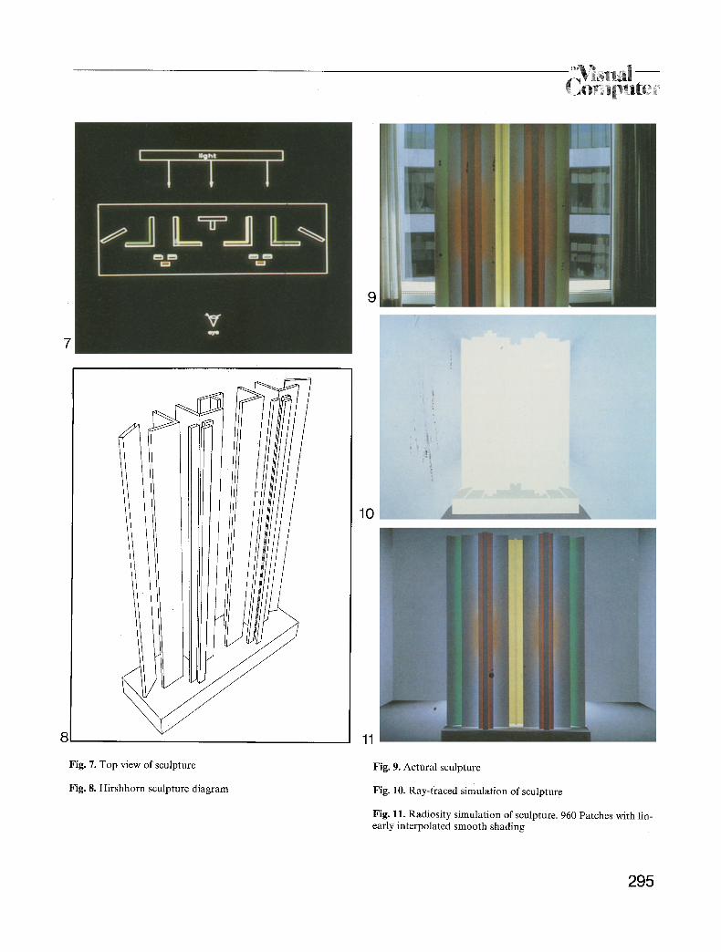
Fig. 7. Top view of sculpture
Fig. 8. Hirshhorn sculpture diagram
10
11
Fig. 9. Actural sculpture
Fig. 10. Ray-traced simulation of sculpture
Fig. 11. Radiosity simulation of sculpture. 960 Patches with lin- early interpolated smooth shading
295
the ray tracing approach for simulating diffuse en- vironments (Goral 1985). A sculpture by John Ferren, entitled "Construction in Wood, A Daylight Experiment", and existing in the Hirshhorn Museum in Washington, DC, was modeled and simulated using both techniques. The sculpture consists of painted wooden panels and background lighting arranged in such a way that the perceived colors are dependent upon the inter- actions between panels. Figure 7 shows a top view of the sculpture, and Fig. 8 displays a line drawing perspective view. Each panel is painted white on the front and a particular color on the back. The main light source is a window in the back of the sculpture. When viewing the real sculpture, the white panels appear colored due to the reflection from the backs of the colored panels located in front of them. The col- ored panels have effectively become colored light sources. Figure 9 is a front view photograph of the sculpture. The environment was modeled as diffuse surfaces and rendered with a ray-tracer of the Cornell testbed image synthesis system (Weghorst et al. 1984). Point light sources with cosine distributions were used, one in the back of the sculpture and one with dimmer intensity in the front. Since all panels are diffuse, the ray from the eye hits the front panels and stops, resulting in the all white simulated image shown in Fig. 10. The same environment was modeled using the ra- diosity method. The majority of the back wall be- hind the sculpture was the main light source. By using approximately correct reflectivity values in three color bands, and subdividing the sculpture into 960 patches, the image of Fig. 11 was obtained. The results clearly demonstrate the capability of the radiosity method to simulate object-to-object reflections and produces the color bleeding effects normally occurring in diffuse environments.
New advances and conclusions
The major difficulty with the radiosity approach is the expensive calculations required to establish the relationship between discrete elements in the environment, and the computational time required to solve the resulting simultaneous equations. In order to improve image quality, it is logical to as- sume that the environment must be finely discre- tized to obtain accurate results, particularly in re-
gions that exhibit high intensity gradients. For many discrete patches, the interdependence be- tween surfaces implies solution techniques which are computationally intractable. A new computational procedure, borrowed from structural engineering, uses "substructuring" to re- duce the calculation time. The premise of this con- cept is that an accurate solution for the radiosity at a point can be obtained with the global radiosit- ies generated from a coarse approximate solution. This method, described in Cohen and Greenberg (1986), lends itself to an adaptive subdivision tech- nique where areas in a scene with high intensity gradients can be adaptively subdivided. In a man- ner similar to the Warnock hidden surface algo- rithm, the iterative solution converges to a more and more accurate representation of the radiosities across surfaces. A generalization of the radiosity method to include transmitting and specularly reflecting surfaces is described by Rushmeier (1985). More recently, two new advances have been docu- mented, extending the radiosity procedure further. In this issue, Baum et al. (1986) describe how the method can be utilized in dynamic environments, ones in which the objects change position relative to each other (Baum et al. 1986). At the 1986 SIG- GRAPH convention, Immel will present his work on how the radiosity method can be extended to non-diffuse environments (Immel et al. 1986). Also in the summer of 1986, an article by Meyer et al. will be published describing physical experiments verifying the radiosity method by comparing a physical model with the results of a radiosity simu- lation.
Acknowledgements. The research summarized in this paper was conducted at Cornell University's Program of Computer Graphics and was partially supported by the National Science Foundation (Grant Number DCR8203979). As with all of our research efforts, many people contributed to the work presented. Particular thanks must go to Cindy Goral who modeled the sculpture simulation, and who first presented the work in her thesis. The authors are also indebted to Holly Rnshmeier, David Immel, and Gary Meyer for their contributions.
References Baum DR, Wallace JR, Cohen MF, Greenberg DP (1986) The
back-buffer algorithm: An extension of the radiosity method to dynamic environments. The Visual Computer 2:298-306
296
Cohen MF, Greenberg DP (1985) The hemi-cube: A radiosity solution for complex environments. ACM SIGGRAPH (Proc 1985)
Cohen MF, Greenberg DP, Immel DS, Brock PJ (1986) An efficient radiosity approach for realistic image synthesis. IEEE Comput Graph Appl
Foley JD, Van Dam A (1982) Fundamentals of Computer Graphics. Addison-Wesley Publishing Co
Goral CM, Torrance KE, Greenberg DP, Battaile B (1984) Mo- deling the Interaction of Light Between Diffuse Surfaces. ACM Comput Graph (Proc 1984)
Goral CM (1985) A Model for the Interaction of Light Between Diffuse Surfaces. Master's Thesis, Cornell University
Gouraud H (1971) Computer Display of Curved Surfaces. Ph.D. Dissertation, University of Utah
Hall R (1986) A characterization of illumination models and shading techniques. The Visual Computer 2:268~77
Immel DS, Cohen MF, Greenberg DP (1986) A Radiosity Method for Non-Diffuse Environments. ACM SIGGRAPH (Proc)
Meyer GW, Rushmeier HE, Cohen MF, Greenberg DP Tor- rance KE: An Experimental Assessment of Computer Graphics Images. Transactions on Graphics (to be pub- lished)
Nishita T, Nakamae E (1985) Continuous Tone Representation of Three-Dimensional Objects Taking Account of Shadows and Interreflection. ACM SIGGRAPH (Proc)
Phong TT (1973) Illumination for Computer Generated Images. Ph.D. Dissertation, University of Utah
Rushmeier HR (1986) Extending the Radiosity Method to Transmitting and Specularly Reflecting Surfaces. Master's Thesis. Cornell University
Sparrow EM, Cess RD (1978) Radiation Heat Transfer. Hemi- sphere Publishing Corporation
Weghorst H, Hooper GJ, Greenberg DP (1984) Improved Com- putational Methods for Ray Tracing. ACM Trans Graph
Whitted T (1980) An Improved Illumination Model for Shaded Display. Commun ACM
297


![Introduction to Radiosity · EECS 487: Interactive Computer Graphics An[other] Intro to Radiosity(1/3) • The radiometric term radiosity means the rate at which energy leaves a surface,](https://img.pdfslide.net/doc/110x75/5fc3a89f74fa74617b240ea3/introduction-to-eecs-487-interactive-computer-graphics-another-intro-to-radiosity13.jpg)