Embed Size (px)
Citation preview
Author’s Name Name of the Paper Session
DYNAMIC POSITIONING CONFERENCESeptember 28-30, 2004
Sensors
RADius, a New Contribution to Demanding
Close-up DP Operations
Trond Schwenke
Kongsberg Seatex AS, Trondheim, Norway
Trond Schwenke Sensors 2 RADius, a new contribution to demanding close-up DP operations
DP Conference Houston September 28-30, 2004 Page 1
ABSTRACTKongsberg Seatex AS has developed a new relative positioning system, RADius, for short-rangepositioning applications, which currently is in use in the North Sea. The system is designed for “close by”DP operations where the need for robust and reliable performance is critical. Statistics shows anincreasing number of contacts or collisions between vessels and installations offshore. As a consequenceseveral operators requires DP class 2 vessels for operations within safety zones of their installations.Further IMO guidelines (ref [2]) require minimum three reference systems for class 2 and 3 DP vessels.RADius is developed to meet these requirements and is a contribution to increase the safety for thesekinds of operations. RADius utilizes FM-CW (Frequency Modulated – Continuous Wave) technology tomeasure range and bearing to one or several transponders located on target vessel or installation. Thesystem is fully solid state without any moving parts and operates in all weather conditions. Relevantoperational scenarios for use of the system are also described.
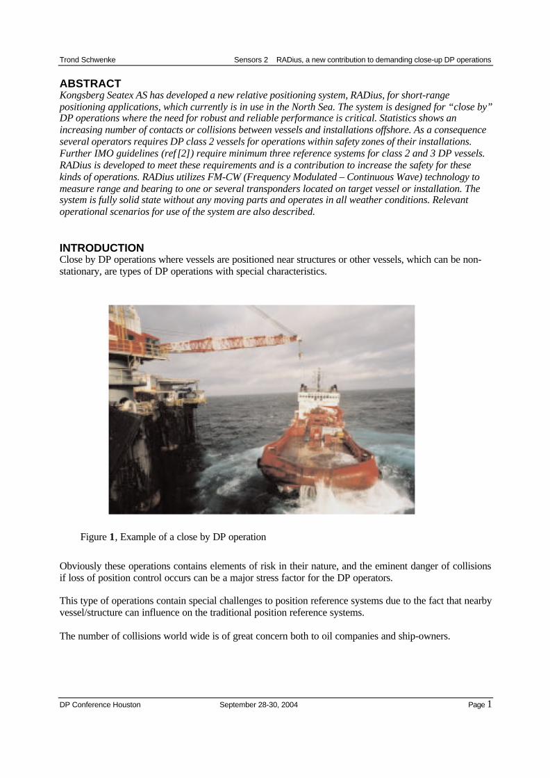
INTRODUCTIONClose by DP operations where vessels are positioned near structures or other vessels, which can be non-stationary, are types of DP operations with special characteristics.
Figure 1, Example of a close by DP operation
Obviously these operations contains elements of risk in their nature, and the eminent danger of collisionsif loss of position control occurs can be a major stress factor for the DP operators.
This type of operations contain special challenges to position reference systems due to the fact that nearbyvessel/structure can influence on the traditional position reference systems.
The number of collisions world wide is of great concern both to oil companies and ship-owners.
Trond Schwenke Sensors 2 RADius, a new contribution to demanding close-up DP operations
DP Conference Houston September 28-30, 2004 Page 2
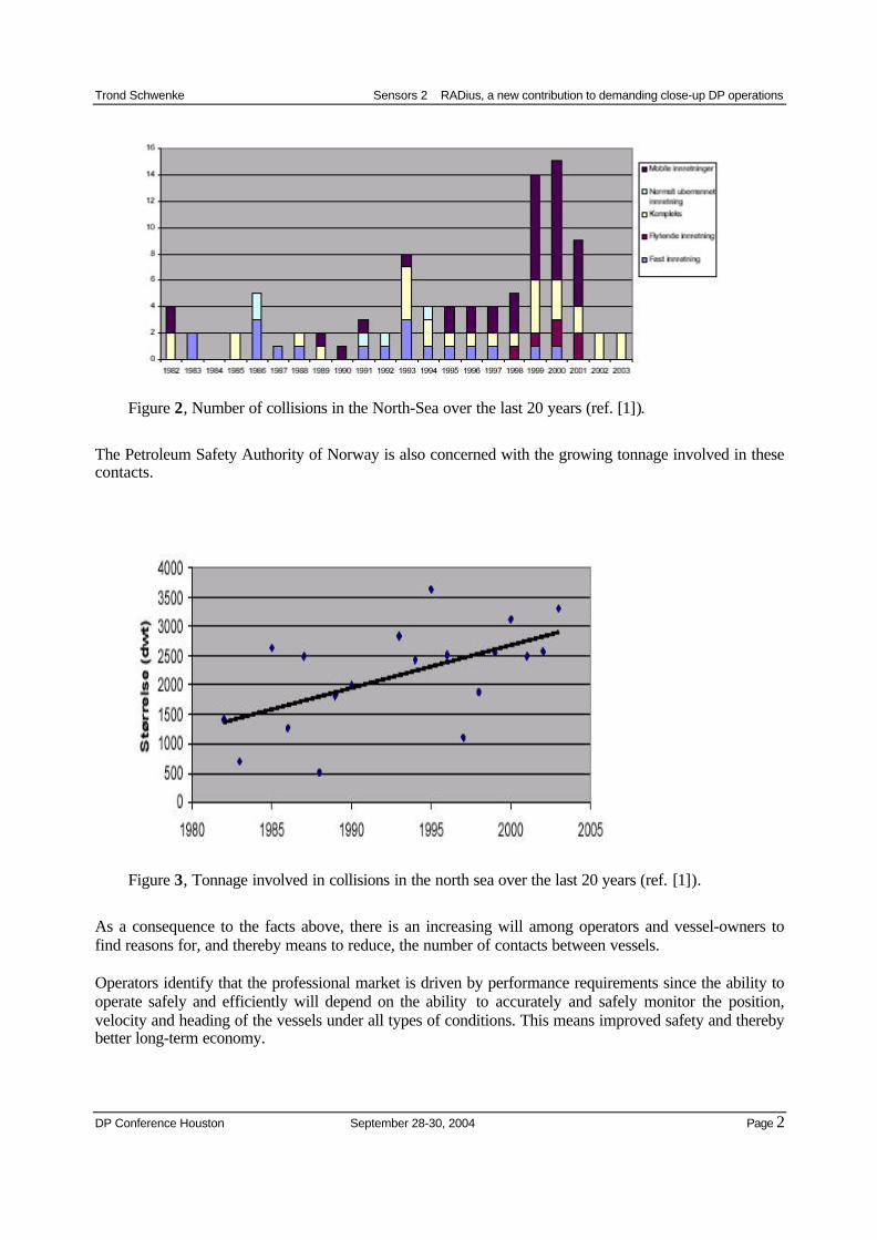
Figure 2, Number of collisions in the North-Sea over the last 20 years (ref. [1]).
The Petroleum Safety Authority of Norway is also concerned with the growing tonnage involved in thesecontacts.
Figure 3, Tonnage involved in collisions in the north sea over the last 20 years (ref. [1]).
As a consequence to the facts above, there is an increasing will among operators and vessel-owners tofind reasons for, and thereby means to reduce, the number of contacts between vessels.
Operators identify that the professional market is driven by performance requirements since the ability tooperate safely and efficiently will depend on the ability to accurately and safely monitor the position,velocity and heading of the vessels under all types of conditions. This means improved safety and therebybetter long-term economy.
Trond Schwenke Sensors 2 RADius, a new contribution to demanding close-up DP operations
DP Conference Houston September 28-30, 2004 Page 3
As a consequence, more and more of the contractors demand DP vessels for operation within safety zonesof installations. The introduction of DP vessels has however not solved all the problems and therequirements have shown a tendency to increase to class 2 DP vessels.
Quote from the IMO guidelines, chapter 3.4.3 Position reference systems, ref [2]:
.2 For equipment classes 2 and 3, at least three position reference systems should be installed andsimultaneously available to the DP-control system during operation.
.3 When two or more position reference systems are required, they should not all be of the sametype, but based on different principles and suitable for the operating conditions.
Due to the way the IMO requirements above are formulated, there has been a discussion whether two canbe of the same type while a third differ both in system and principle. Further whether all have to bedifferent types and at least one based on different principle compared to the other two. The optimalsolution is however if all three are different and based on different principles as long as all have sufficientperformance. RADius is a mean to fulfill these optimal requirements.
THE RADius SYSTEM (patent pending)RADius is developed to be a position reference system contributing to increase redundancy, robustnessand thereby the availability and safety of “close by” DP operations.
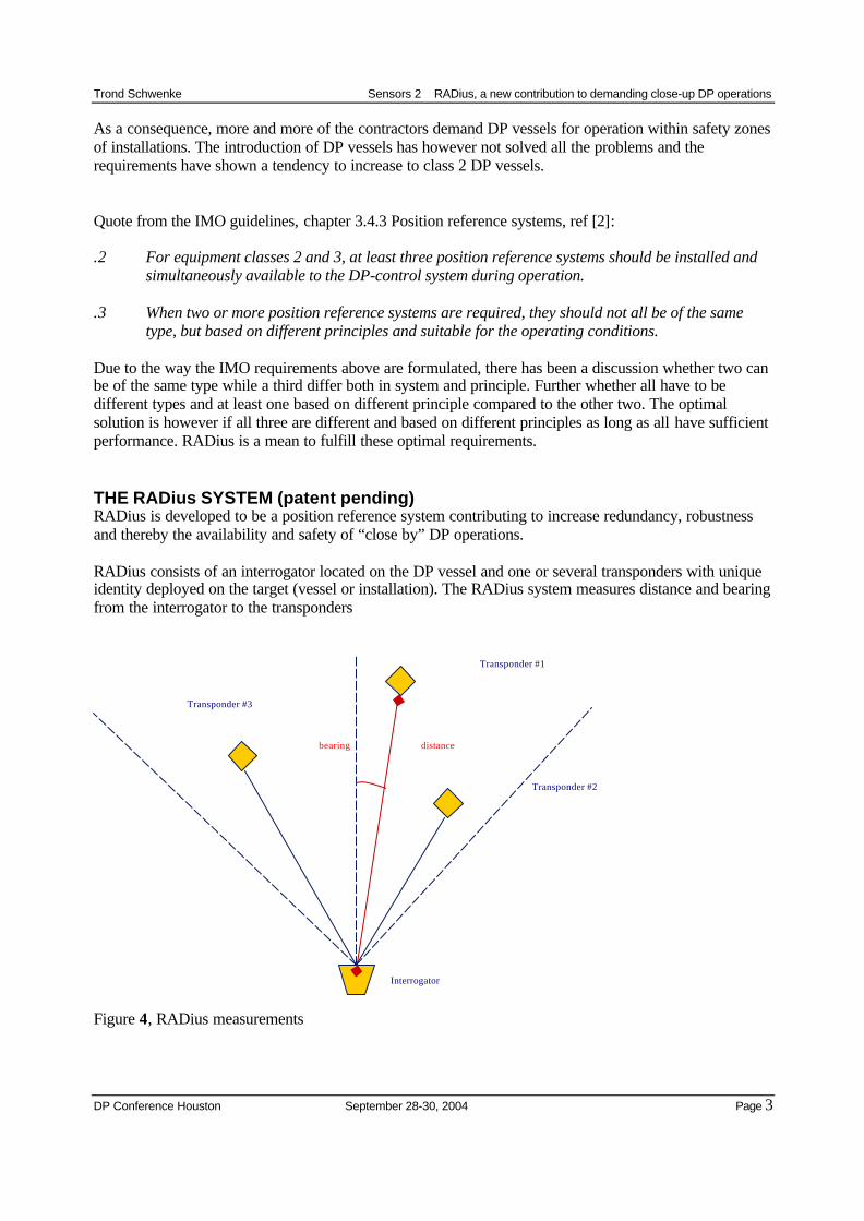
RADius consists of an interrogator located on the DP vessel and one or several transponders with uniqueidentity deployed on the target (vessel or installation). The RADius system measures distance and bearingfrom the interrogator to the transponders
Figure 4, RADius measurements
Interrogator
Transponder #1
distancebearing
Transponder #3
Transponder #2
Trond Schwenke Sensors 2 RADius, a new contribution to demanding close-up DP operations
DP Conference Houston September 28-30, 2004 Page 4
Operational, one transponder is sufficient for DP operations and the system can utilize up to fivetransponders simultaneously, increasing robustness and reliability. A transponder can serve severalinterrogators simultaneously providing multi user functionality in the system.
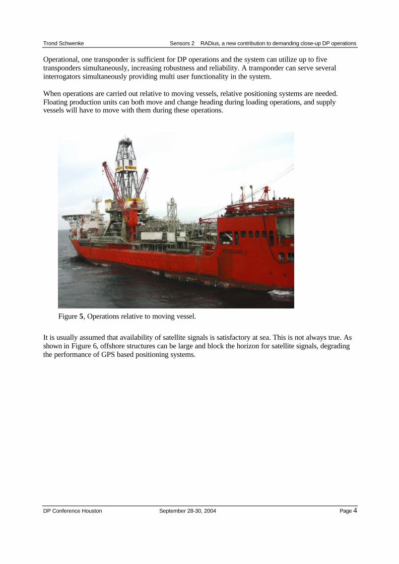
When operations are carried out relative to moving vessels, relative positioning systems are needed.Floating production units can both move and change heading during loading operations, and supplyvessels will have to move with them during these operations.
Figure 5, Operations relative to moving vessel.
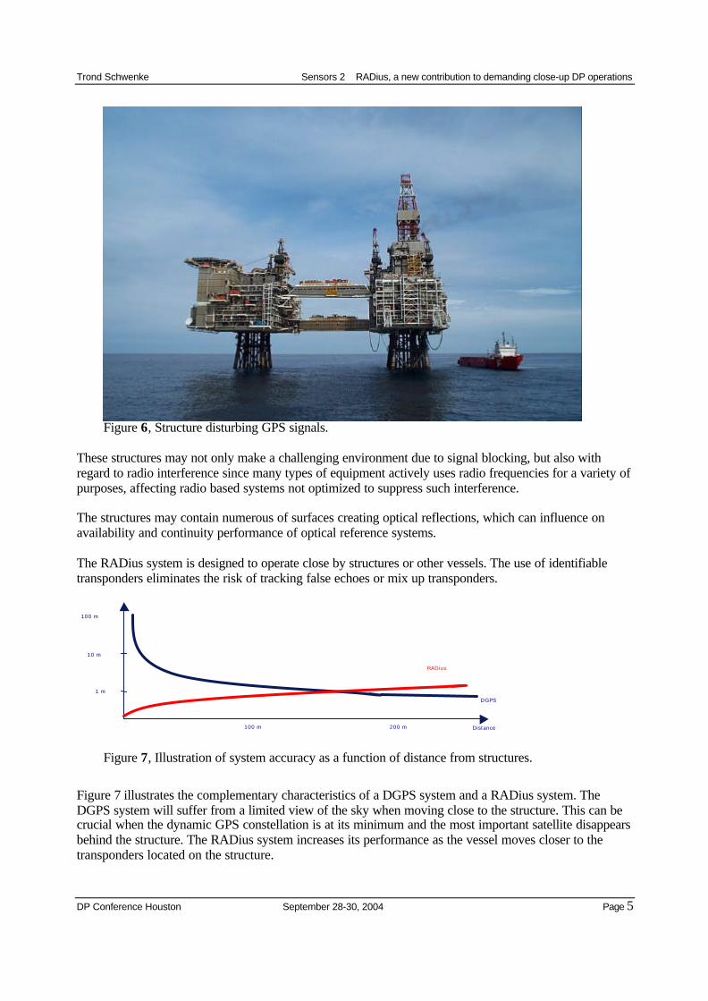
It is usually assumed that availability of satellite signals is satisfactory at sea. This is not always true. Asshown in Figure 6, offshore structures can be large and block the horizon for satellite signals, degradingthe performance of GPS based positioning systems.
Trond Schwenke Sensors 2 RADius, a new contribution to demanding close-up DP operations
DP Conference Houston September 28-30, 2004 Page 5
Figure 6, Structure disturbing GPS signals.
These structures may not only make a challenging environment due to signal blocking, but also withregard to radio interference since many types of equipment actively uses radio frequencies for a variety ofpurposes, affecting radio based systems not optimized to suppress such interference.
The structures may contain numerous of surfaces creating optical reflections, which can influence onavailability and continuity performance of optical reference systems.
The RADius system is designed to operate close by structures or other vessels. The use of identifiabletransponders eliminates the risk of tracking false echoes or mix up transponders.
Figure 7, Illustration of system accuracy as a function of distance from structures.
Figure 7 illustrates the complementary characteristics of a DGPS system and a RADius system. TheDGPS system will suffer from a limited view of the sky when moving close to the structure. This can becrucial when the dynamic GPS constellation is at its minimum and the most important satellite disappearsbehind the structure. The RADius system increases its performance as the vessel moves closer to thetransponders located on the structure.
DGPS
10 m
100 m 200 m
RADius
1 m
100 m
Distance
Trond Schwenke Sensors 2 RADius, a new contribution to demanding close-up DP operations
DP Conference Houston September 28-30, 2004 Page 6
MEASUREMENT PRINCIPLES
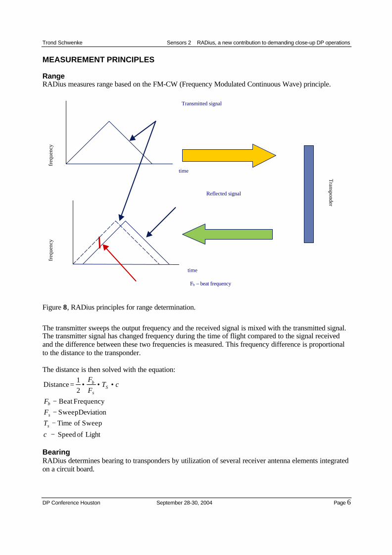
RangeRADius measures range based on the FM-CW (Frequency Modulated Continuous Wave) principle.
Figure 8, RADius principles for range determination.
The transmitter sweeps the output frequency and the received signal is mixed with the transmitted signal.The transmitter signal has changed frequency during the time of flight compared to the signal receivedand the difference between these two frequencies is measured. This frequency difference is proportionalto the distance to the transponder.
The distance is then solved with the equation:
Light of Speed
Sweep of TimeDeviation Sweep
FrequencyBeat 21
Distance
−
−−−
•••=
cTFF
cTFF
s
s
b
Ss
b
BearingRADius determines bearing to transponders by utilization of several receiver antenna elements integratedon a circuit board.
Transmitted signal
time
Reflected signal
time
Fb – beat frequency
Transponder
freq
uenc
yfr
eque
ncy
Trond Schwenke Sensors 2 RADius, a new contribution to demanding close-up DP operations
DP Conference Houston September 28-30, 2004 Page 7
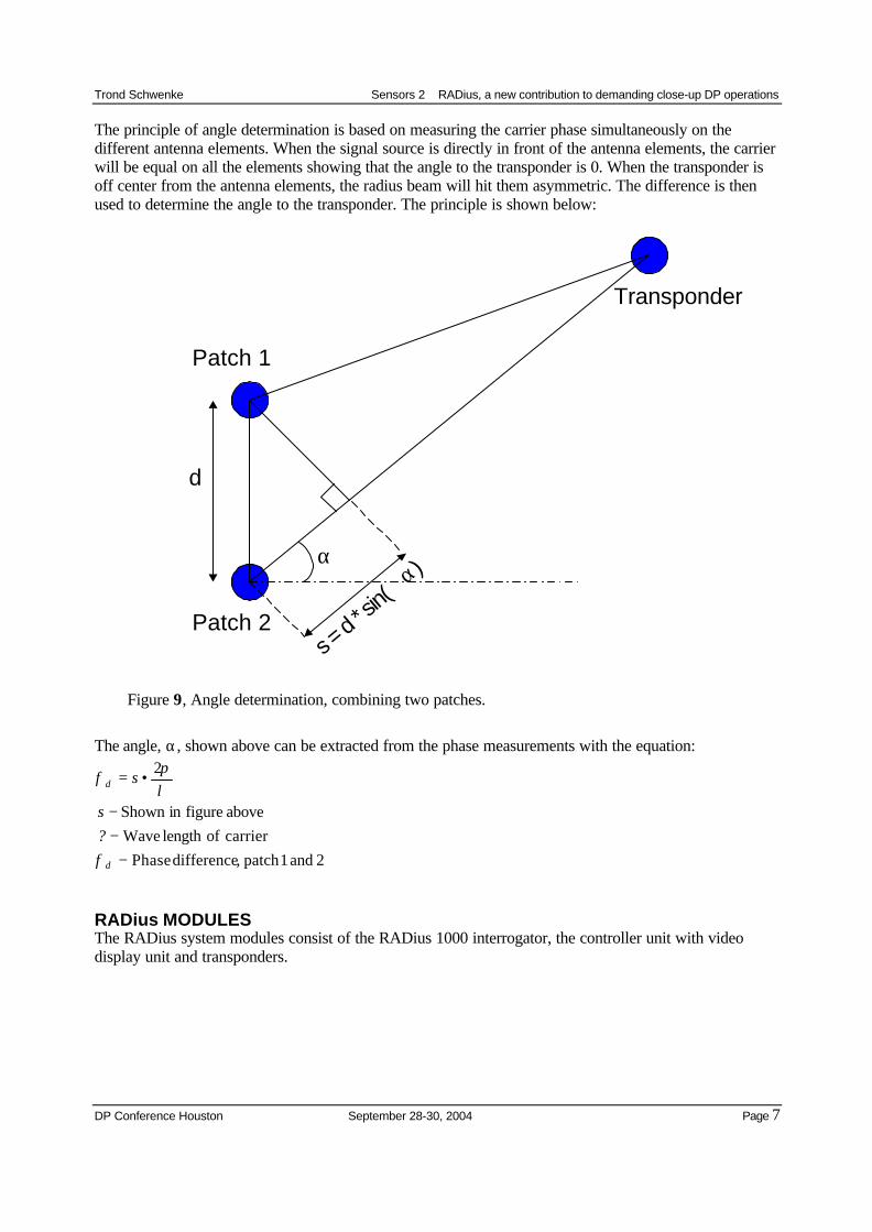
The principle of angle determination is based on measuring the carrier phase simultaneously on thedifferent antenna elements. When the signal source is directly in front of the antenna elements, the carrierwill be equal on all the elements showing that the angle to the transponder is 0. When the transponder isoff center from the antenna elements, the radius beam will hit them asymmetric. The difference is thenused to determine the angle to the transponder. The principle is shown below:
α
d
Patch 1
Patch 2
Transponder
s = d *
sin(
α)
Figure 9, Angle determination, combining two patches.
The angle, α, shown above can be extracted from the phase measurements with the equation:
2 and 1patch ,difference Phasecarrier oflength Waveabove figurein Shown
2
−−−
•=
d
d
?s
s
φ
λπ
φ
RADius MODULESThe RADius system modules consist of the RADius 1000 interrogator, the controller unit with videodisplay unit and transponders.
Trond Schwenke Sensors 2 RADius, a new contribution to demanding close-up DP operations
DP Conference Houston September 28-30, 2004 Page 8
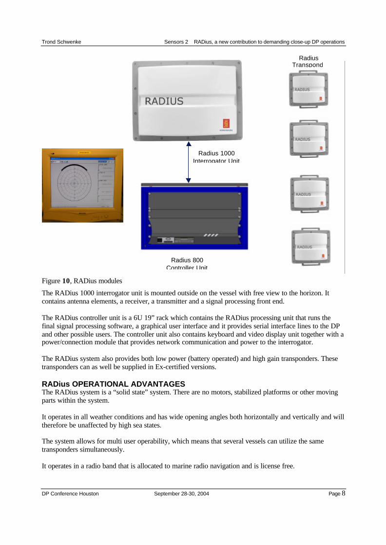
Figure 10, RADius modules
The RADius 1000 interrogator unit is mounted outside on the vessel with free view to the horizon. Itcontains antenna elements, a receiver, a transmitter and a signal processing front end.
The RADius controller unit is a 6U 19” rack which contains the RADius processing unit that runs thefinal signal processing software, a graphical user interface and it provides serial interface lines to the DPand other possible users. The controller unit also contains keyboard and video display unit together with apower/connection module that provides network communication and power to the interrogator.
The RADius system also provides both low power (battery operated) and high gain transponders. Thesetransponders can as well be supplied in Ex-certified versions.
RADius OPERATIONAL ADVANTAGESThe RADius system is a “solid state” system. There are no motors, stabilized platforms or other movingparts within the system.
It operates in all weather conditions and has wide opening angles both horizontally and vertically and willtherefore be unaffected by high sea states.
The system allows for multi user operability, which means that several vessels can utilize the sametransponders simultaneously.
It operates in a radio band that is allocated to marine radio navigation and is license free.
Radius 800Controller Unit
RadiusTranspond
Radius 1000Interrogator Unit
Trond Schwenke Sensors 2 RADius, a new contribution to demanding close-up DP operations
DP Conference Houston September 28-30, 2004 Page 9
The system efficiently mitigates radio interference. This is due to the wide frequency range over whichthe transmitter is sweeping. The receiver has a very narrow bandwidth since it operates on the mixedtransmitted/received signal. This means that radio noise in the band typically occur in narrow bands thatare swept past and is effectively “clipped” out of the data in the signal processing.
The system evaluates its performance and outputs accuracy estimates of distance and angle measurementsto the DP.
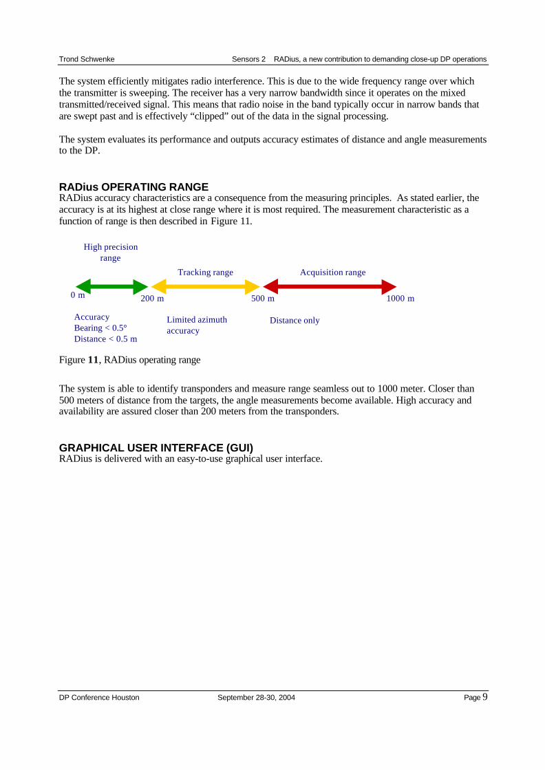
RADius OPERATING RANGERADius accuracy characteristics are a consequence from the measuring principles. As stated earlier, theaccuracy is at its highest at close range where it is most required. The measurement characteristic as afunction of range is then described in Figure 11.
Figure 11, RADius operating range
The system is able to identify transponders and measure range seamless out to 1000 meter. Closer than500 meters of distance from the targets, the angle measurements become available. High accuracy andavailability are assured closer than 200 meters from the transponders.
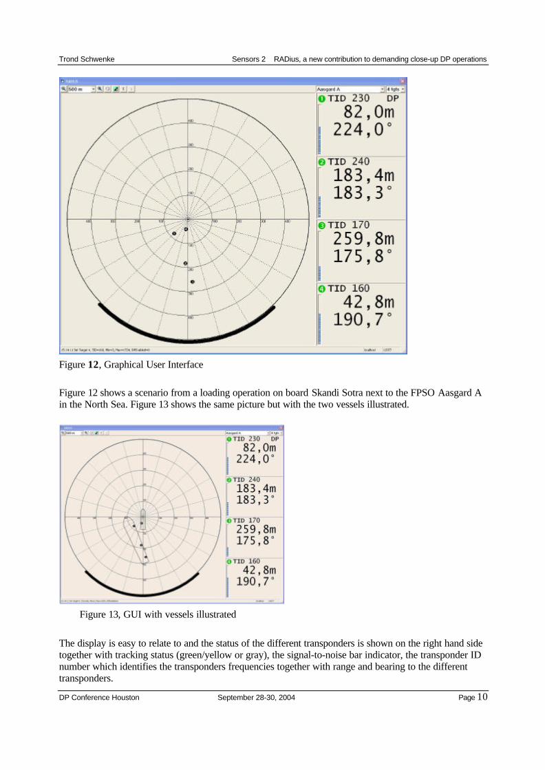
GRAPHICAL USER INTERFACE (GUI)RADius is delivered with an easy-to-use graphical user interface.
High precisionrange
Tracking range Acquisition range
200 m 500 m 1000 m0 m
AccuracyBearing < 0.5°Distance < 0.5 m
Limited azimuthaccuracy
Distance only
Trond Schwenke Sensors 2 RADius, a new contribution to demanding close-up DP operations
DP Conference Houston September 28-30, 2004 Page 10
Figure 12, Graphical User Interface
Figure 12 shows a scenario from a loading operation on board Skandi Sotra next to the FPSO Aasgard Ain the North Sea. Figure 13 shows the same picture but with the two vessels illustrated.
Figure 13, GUI with vessels illustrated
The display is easy to relate to and the status of the different transponders is shown on the right hand sidetogether with tracking status (green/yellow or gray), the signal-to-noise bar indicator, the transponder IDnumber which identifies the transponders frequencies together with range and bearing to the differenttransponders.
Trond Schwenke Sensors 2 RADius, a new contribution to demanding close-up DP operations
DP Conference Houston September 28-30, 2004 Page 11
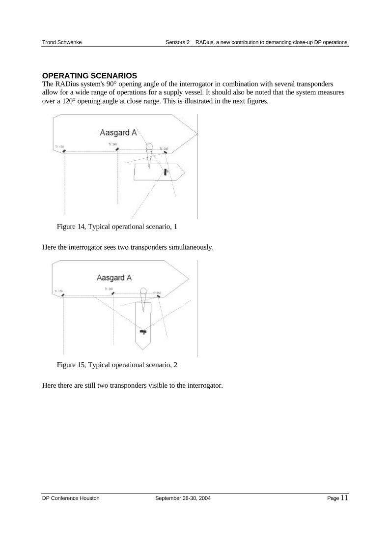
OPERATING SCENARIOSThe RADius system's 90° opening angle of the interrogator in combination with several transpondersallow for a wide range of operations for a supply vessel. It should also be noted that the system measuresover a 120° opening angle at close range. This is illustrated in the next figures.
Figure 14, Typical operational scenario, 1
Here the interrogator sees two transponders simultaneously.
Figure 15, Typical operational scenario, 2
Here there are still two transponders visible to the interrogator.
Trond Schwenke Sensors 2 RADius, a new contribution to demanding close-up DP operations
DP Conference Houston September 28-30, 2004 Page 12
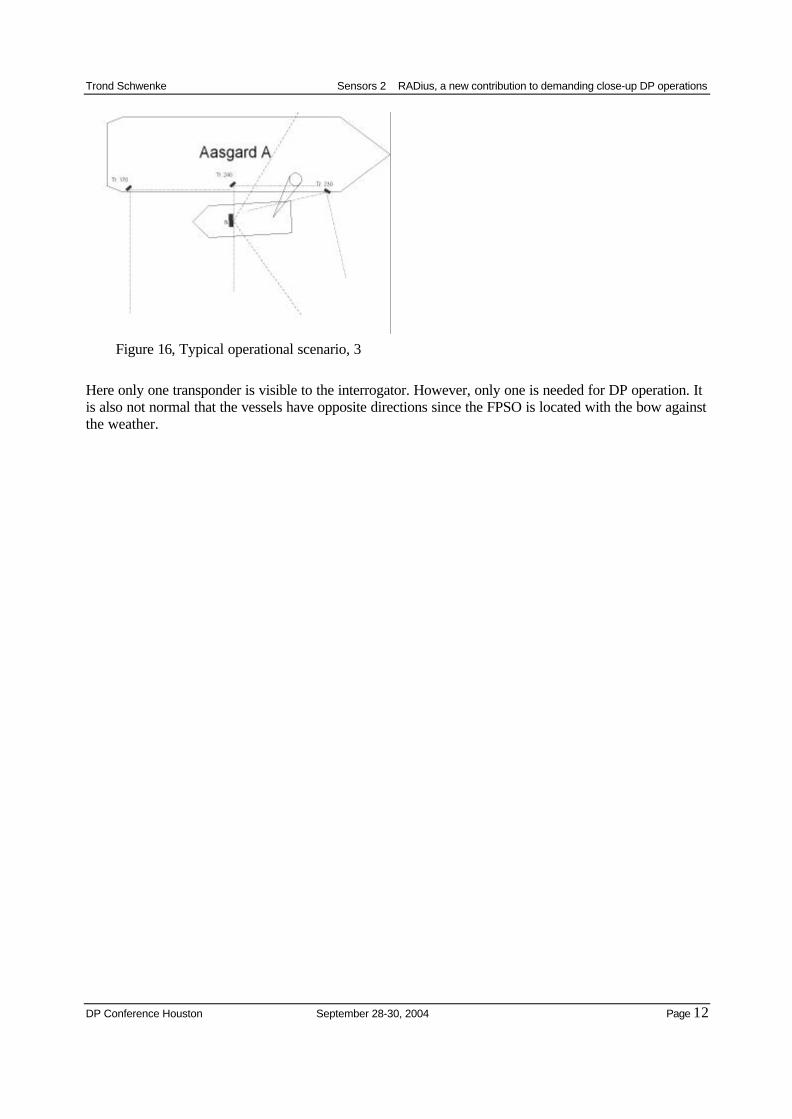
Figure 16, Typical operational scenario, 3
Here only one transponder is visible to the interrogator. However, only one is needed for DP operation. Itis also not normal that the vessels have opposite directions since the FPSO is located with the bow againstthe weather.
Trond Schwenke Sensors 2 RADius, a new contribution to demanding close-up DP operations
DP Conference Houston September 28-30, 2004 Page 13
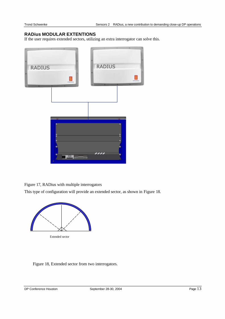
RADius MODULAR EXTENTIONSIf the user requires extended sectors, utilizing an extra interrogator can solve this.
Figure 17, RADius with multiple interrogators
This type of configuration will provide an extended sector, as shown in Figure 18.
Figure 18, Extended sector from two interrogators.
Extended sector
Trond Schwenke Sensors 2 RADius, a new contribution to demanding close-up DP operations
DP Conference Houston September 28-30, 2004 Page 14
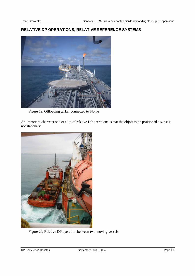
RELATIVE DP OPERATIONS, RELATIVE REFERENCE SYSTEMS
Figure 19, Offloading tanker connected to Norne
An important characteristic of a lot of relative DP operations is that the object to be positioned against isnot stationary.
Figure 20, Relative DP operation between two moving vessels.
Trond Schwenke Sensors 2 RADius, a new contribution to demanding close-up DP operations
DP Conference Houston September 28-30, 2004 Page 15
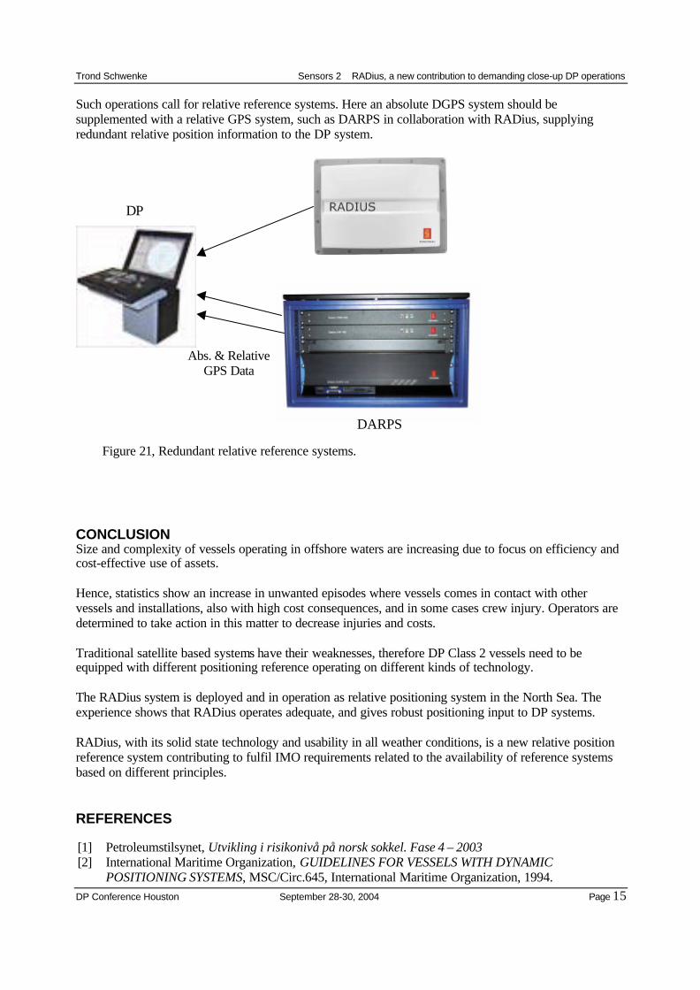
Such operations call for relative reference systems. Here an absolute DGPS system should besupplemented with a relative GPS system, such as DARPS in collaboration with RADius, supplyingredundant relative position information to the DP system.
Figure 21, Redundant relative reference systems.
CONCLUSIONSize and complexity of vessels operating in offshore waters are increasing due to focus on efficiency andcost-effective use of assets.
Hence, statistics show an increase in unwanted episodes where vessels comes in contact with othervessels and installations, also with high cost consequences, and in some cases crew injury. Operators aredetermined to take action in this matter to decrease injuries and costs.
Traditional satellite based systems have their weaknesses, therefore DP Class 2 vessels need to beequipped with different positioning reference operating on different kinds of technology.
The RADius system is deployed and in operation as relative positioning system in the North Sea. Theexperience shows that RADius operates adequate, and gives robust positioning input to DP systems.
RADius, with its solid state technology and usability in all weather conditions, is a new relative positionreference system contributing to fulfil IMO requirements related to the availability of reference systemsbased on different principles.
REFERENCES
[1] Petroleumstilsynet, Utvikling i risikonivå på norsk sokkel. Fase 4 – 2003 [2] International Maritime Organization, GUIDELINES FOR VESSELS WITH DYNAMIC
POSITIONING SYSTEMS, MSC/Circ.645, International Maritime Organization, 1994.
DARPS
Abs. & RelativeGPS Data
DP