Embed Size (px)
Citation preview

Radon Mitigation using Heat Recovery Ventilation system in a Swedish Detached House
KERAMATOLLAH AKBARI1, ROBERT OMAN2
1Mälardalen University, PhD student, School of Sustainable Development of Society and Technology, SWEDEN
2Mälardalen University, Lecturer at School of Sustainable Development of Society and Technology, SWEDEN
1 [email protected] ; [email protected]
Abstract: Balanced ventilation with heat recovery has strong effects on radon mitigation and energy saving in residential buildings. This new technology enables improvement of both indoor air quality and energy efficiency without sacrificing either. Reducing radon by means of forced ventilation requires an increase in outdoor supplied air (i.e. ventilation rate), which in turn can increase energy use. Energy losses in ventilation systems are inevitable, but new technologies such as heat recovery systems make it possible to recover most of this ventilation heat loss. Heat recovery ventilation systems, which recover energy from exhaust air, can significantly reduce ventilation losses, and balancing the indoor air pressure plays a positive role in the effectiveness of ventilation to reduce and mitigate radon levels and control indoor air quality. This paper describes a case study which considers the effects of a heat recovery ventilation system on the radon concentration and energy consumption in a detached house in Stockholm, Sweden. The performance of the heat recovery ventilation system is examined with respect to radon mitigation and energy saving by measuring the radon concentration and analyzing the life cycle cost in winter. The results of the measurements and dynamic simulation showed that a heat recovery ventilation system was able to reduce the radon level from around 600 Bq.m-3 to below 100 Bq.m-3 and reduce energy loss from ventilation by 80%, equivalent to around 3500 kWh per year. The results of life cycle cost analysis used to assess total costs showed that this system is cost-effective and investment would pay for itself in 12 years. It should be noted that this saving is a representative sample, and that actual savings would be influenced by a large number of factors. IDA 4.0 Indoor Climate and Energy software was used to perform the dynamic simulations. Keywords: Energy saving, Residential building, Heat recovery, Ventilation, Radon, IDA 4.0 Nomenclature and abbreviations 퐶 radon concentration ( Bq.m-3)
퐺 radon generation rate (Bq.m-3.s-1)
휆 radon decay constant (2.1× 10⁻⁶ s-1)
퐴 surface (푚 )
Ar radium activity (Bq.kg-1)
푒 radon emanation fraction
휌 soil density (kg.m-3)
푝 porosity
푡 temperature (°C) 푤 water content of air (g.kg-1) 휂 temperature efficiency 휂 moisture efficiency
11 Outdoor air condition 12 Supply air condition 21 Extract air condition 22 Exhaust air condition
푉 volume of the house (푚 )
휆 ventilation rate (ℎ )
Q energy (kW.h)
푄 recovered energy (kW.h)
B0 all savings in net present value method
A0 initial investment
퐼 net present value factor
푖 interest rate
b annual savings in monetary units
q annual energy cost escalation rate
n time in years
RH relative humidity
ERV energy recovery ventilator CRM
continuous radon monitor
ATD alpha track detector
HDD heating degree days
WSEAS TRANSACTIONS on ENVIRONMENT and DEVELOPMENT Keramatollah Akbari, Robert Oman
E-ISSN: 2224-3496 73 Issue 3, Volume 8, July 2012
퐸 radon exhalation rate (Bq.푚 .ℎ )
Ach air change rate
HRV heat recovery ventilator
SHF specific heat factor
1 Introduction Energy consumption in the building sector continues to grow steadily, and makes up around 40% of total energy consumption in many countries. In Sweden, about 61 % of energy use in this sector is used for space heating and domestic hot water [1].
This has to be taken into account when applying an energy efficient ventilation system as a radon mitigation strategy to prevent unnecessary energy consumption in cold climates. The prevalence of heat recovery ventilation (HRV) systems in residential buildings in Sweden has increased over the last few decades. The increase in energy efficiency through heat recovery systems such as these contributes to a more sustainable society.
The aim of this study is to show the effectiveness of HRV systems for controlling both radon concentration and energy consumption. This paper investigates the potential of energy recovery in a rotary heat exchanger and the life cycle cost of such a system.
This approach can help many of the more than 500,000 dwellings in Sweden which suffer from elevated radon concentrations in the range 200-800 Bq.m-3, and the 1,000,000 dwellings that have radon concentrations of 100-200 Bq.m-3 [2], which need increased ventilation to reduce indoor radon concentrations.
Several studies have compared various ventilation systems to show the advantages of heat recovery ventilation systems in cold climates [3-6]. One of these studies showed that energy efficiency could be improved by up to 67% compared to a traditional exhaust ventilation system by using a heat recovery system with a nominal temperature efficiency of 80% [3].
Comparison between an exhaust fan and a heat recovery ventilation system in a cold climate showed that a heat exchanger air-to-air ventilation system can save up to 2710 kWh per year compared to a traditional ventilation system and space heating. This amounts to an increase in energy efficiency of around 30% in an insulated house. This is the best current technology for reducing radon levels [7-9].
Nazaroff et al. calculated that annual energy savings of 6000 kWh (equivalent to 720 USD at current electricity prices) were obtainable [6], and
improvements in performance of heat exchanger components since this study suggest that further savings could be made.
2 Investigation and methods The investigation was conducted in a single family detached house, where radon levels were measured in conjunction with remedial changes to reduce these levels, amongst these a rotary heat exchanger unit. The radon measurement tools included an electronic radon monitor, alpha track detectors.
The indoor climate and energy package IDA was employed as a multizone dynamic simulation software to predict energy consumption and heat recovery of the rotary heat exchanger unit.
Research methods applied in this study include analytical analysis, measurement, dynamic simulation, and life cycle cost analysis. 3 Energy recovery ventilation systems Thermal losses in buildings are generally attributable to ventilation losses and transmission losses of the envelope, and domestic hot water, which is not considered in this work. Ventilation losses are increasing due to the new indoor air quality standards and the focus on reducing indoor radon concentration in cold climates. Reducing losses due to ventilation are therefore expected to have a large impact on energy use.
The best currently available system for reducing ventilation losses and controlling indoor pollution is the recovery ventilator. Recovery ventilation systems have two air streams, provided by a supply and an exhaust fan. The supply and the exhaust air streams are connected by means of an air-to-air heat exchanger which acts as a heat transfer system from the warm air stream, i.e. the indoor air, to the cold air stream, i.e. the outdoor fresh air, without mixing the two streams.
There are two types of recovery ventilators; energy recovery ventilators (ERV), which transfer a certain amount of water vapor (moisture) along with the heat energy; and heat recovery ventilators (HRV), which only exchange heat energy between the incoming and outgoing air streams.
WSEAS TRANSACTIONS on ENVIRONMENT and DEVELOPMENT Keramatollah Akbari, Robert Oman
E-ISSN: 2224-3496 74 Issue 3, Volume 8, July 2012

3.1 Temperature and humidity efficiencies of energy recovery ventilation system A rotary heat exchanger acts as an energy recovery ventilation system. The rotor unit has a high efficiency and recovers up to 80% of the heat and moisture from the air extracted from the home [10]. The rotating wheel (rotor) is made of an air permeable heat transfer matrix which picks up the heat from the exhaust air and releases it as the wheel passes through the cooler air supply.
Depending on the air conditions and the use of desiccant coated rotors, the heat recovery wheel can also transfer moisture, thereby recovering both sensible and latent energy.
Fig.1. shows the incoming and outgoing air streams as they approach the wheel. It is also possible to utilize the heat content in the exhaust air by means of an exhaust air heat pump, but this alternative is not included in the present study.
Fig.1 Air flows through a rotary heat exchanger
with colors indicating different air temperatures. The key factors for evaluating the performance
of rotary heat exchangers are the temperature and humidity efficiencies. They are defined as the ratio between the air condition change achievable by the rotary heat exchanger and the maximum possible condition change of the air. These factors are defined as [11]: Temperature efficiency 휼풕:
휼풕 = 풕ퟏퟐ 풕ퟏퟏ풕ퟐퟏ 풕ퟏퟏ
(1) Moisture efficiency 휂 :
휂 = (2) 4 Case study description 4.1 The detached house The case study building is a detached one family house in Stockholm, built in 1970. This house is a two storey structure, with a lower floor one meter below ground level, and a volume of about 230 m3 on each level. This corresponds to a floor area of about 95 m² per storey.
The foundation of this building is on the bedrock. Initial radon levels were measured at about 3580 Bq.m-3, originating from the floor of the lower level. Radon levels decreased to about 600 Bq.m-3 after sealing parts of the floor and using a radon sump with an exhaust fan on this level as a ventilation system (prior to installing a heat exchanger unit). 4.2 The ventilation system A mechanical ventilation system with an air-to-air heat exchanger unit provides the air supply to the first floor. This unit is a rotary energy recovery system, which recovers both heat (sensible energy) and humidity (latent energy). Fig.2. illustrates the heat exchanger system installed on the first floor.
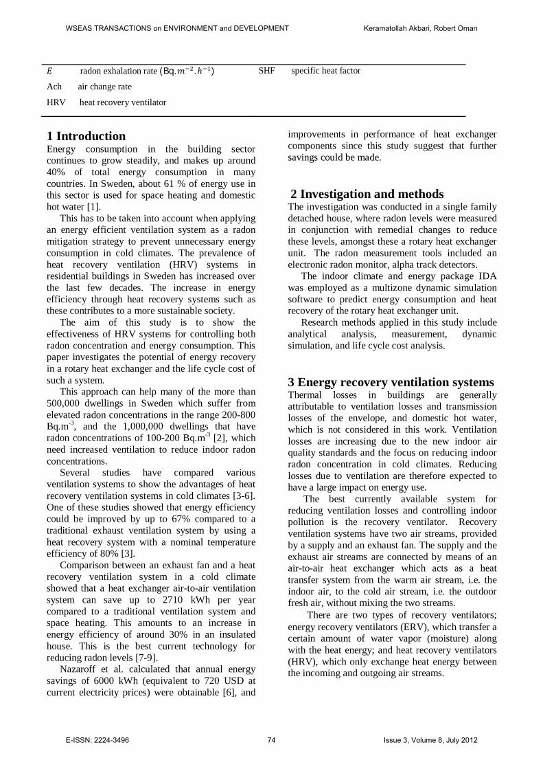
The operating points of the unit can be determined from the diagram shown in Fig.3.
The operating points at 0.5 and 1.0 Ach are shown with the orange dashed and continuous lines respectively in Fig.3.
Given the ventilation rates and Fig.3, it is possible to find the operating rates such as pressure, noise, and fan(s) electrical energy consumption. The unit efficiency was derived from equation (1) as shown below, and the determined values are shown in Table 1.
According to the manufacturer, the maximum temperature and humidity efficiencies of this rotary heat exchanger unit are 80% [10]. These values are not always reached, as demonstrated below:
휂 =14.5 + 7.422 + 7.4
= 74.5%
WSEAS TRANSACTIONS on ENVIRONMENT and DEVELOPMENT Keramatollah Akbari, Robert Oman
E-ISSN: 2224-3496 75 Issue 3, Volume 8, July 2012
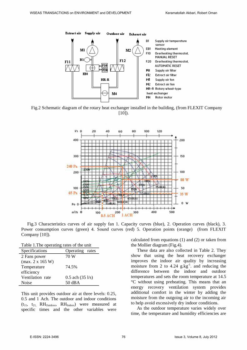
Fig.2 Schematic diagram of the rotary heat exchanger installed in the building, (from FLEXIT Company [10]).
Fig.3 Characteristics curves of air supply fan 1. Capacity curves (blue), 2. Operation curves (black), 3.
Power consumption curves (green) 4. Sound curves (red) 5. Operation points (orange) (from FLEXIT Company [10]).
Table 1.The operating rates of the unit Specifications Operating rates 2 Fans power (max. 2 x 165 W)
70 W
Temperature efficiency
74.5%
Ventilation rate 0.5 ach (35 l/s) Noise 50 dBA This unit provides outdoor air at three levels: 0.25, 0.5 and 1 Ach. The outdoor and indoor conditions (t11, t21, RHOutdoor, RHIndoor) were measured at specific times and the other variables were
calculated from equations (1) and (2) or taken from the Mollier diagram (Fig.4).
These data are also collected in Table 2. They show that using the heat recovery exchanger improves the indoor air quality by increasing moisture from 2 to 4.24 g.kg-1. and reducing the difference between the indoor and outdoor temperatures and sets the room temperature at 14.5 °C without using preheating. This means that an energy recovery ventilation system provides additional comfort in the winter by adding the moisture from the outgoing air to the incoming air to help avoid excessively dry indoor conditions.
As the outdoor temperature varies widely over time, the temperature and humidity efficiencies are
WSEAS TRANSACTIONS on ENVIRONMENT and DEVELOPMENT Keramatollah Akbari, Robert Oman
E-ISSN: 2224-3496 76 Issue 3, Volume 8, July 2012
not constant. A dynamic simulation tool is a therefore a good means of determining the
recovered heat over a month or the whole year.
Fig.4 The air conditioning process for the heating operation
Table 2 Air conditions before and after the recovery ventilation system
Temp ( °C)
Relative Humidity
( %)
Moisture in air
(g.kg-1)
Position
t11= -7.4 98 푤 = 2 Outdoor air condition
t12=14.5 40 푤 = 4.24 Supply air condition
t21= 22 30 푤 = 4. 8 Extract air condition
4.3 Radon measurements Radon concentrations were measured constantly during the winter. The measurement tools included
a continuous radon meter (CRM) and alpha track detectors (ATD). Table 3 shows the results of these measurements.
Table 3 Radon measurements results Date and period
ATD (Bq.m-3)
CRM (Bq.m-
3)
Air change rate (h-1)
Ventilation type
Remedial action
2008-2 (2 weeks)
3580±380 ------ 0.25 Exhaust fan
No action
2010-3-18 (12days)
------ 65±6 0.5 HRV 3connected sumps
WSEAS TRANSACTIONS on ENVIRONMENT and DEVELOPMENT Keramatollah Akbari, Robert Oman
E-ISSN: 2224-3496 77 Issue 3, Volume 8, July 2012
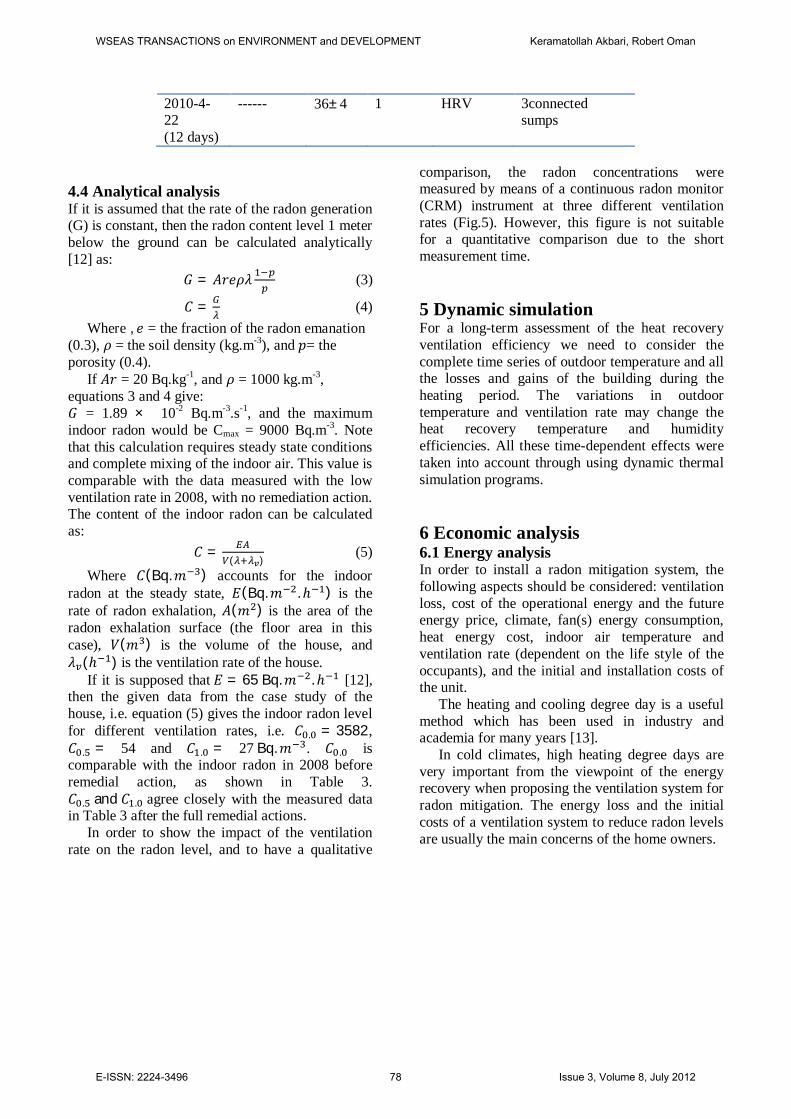
2010-4-22 (12 days)
------ 36±4 1 HRV 3connected sumps
4.4 Analytical analysis If it is assumed that the rate of the radon generation (G) is constant, then the radon content level 1 meter below the ground can be calculated analytically [12] as:
퐺 = 퐴푟푒휌휆 (3)
퐶 = (4) Where , 푒 = the fraction of the radon emanation
(0.3), 휌 = the soil density (kg.m-3), and 푝= the porosity (0.4).
If 퐴푟 = 20 Bq.kg-1, and 휌 = 1000 kg.m-3, equations 3 and 4 give: 퐺 = 1.89 × 10⁻² Bq.m-3.s-1, and the maximum indoor radon would be Cmax = 9000 Bq.m-3. Note that this calculation requires steady state conditions and complete mixing of the indoor air. This value is comparable with the data measured with the low ventilation rate in 2008, with no remediation action. The content of the indoor radon can be calculated as:
퐶 =( )
(5) Where 퐶(Bq.푚 ) accounts for the indoor
radon at the steady state, 퐸(Bq.푚 .ℎ ) is the rate of radon exhalation, 퐴(푚 ) is the area of the radon exhalation surface (the floor area in this case), 푉(푚 ) is the volume of the house, and 휆 (ℎ ) is the ventilation rate of the house.
If it is supposed that 퐸 = 65 Bq.푚 .ℎ [12], then the given data from the case study of the house, i.e. equation (5) gives the indoor radon level for different ventilation rates, i.e. 퐶 . = 3582, 퐶 . = 54 and 퐶 . = 27 Bq.푚 . 퐶 . is comparable with the indoor radon in 2008 before remedial action, as shown in Table 3. 퐶 . and 퐶 . agree closely with the measured data in Table 3 after the full remedial actions.
In order to show the impact of the ventilation rate on the radon level, and to have a qualitative
comparison, the radon concentrations were measured by means of a continuous radon monitor (CRM) instrument at three different ventilation rates (Fig.5). However, this figure is not suitable for a quantitative comparison due to the short measurement time.
5 Dynamic simulation For a long-term assessment of the heat recovery ventilation efficiency we need to consider the complete time series of outdoor temperature and all the losses and gains of the building during the heating period. The variations in outdoor temperature and ventilation rate may change the heat recovery temperature and humidity efficiencies. All these time-dependent effects were taken into account through using dynamic thermal simulation programs.
6 Economic analysis 6.1 Energy analysis In order to install a radon mitigation system, the following aspects should be considered: ventilation loss, cost of the operational energy and the future energy price, climate, fan(s) energy consumption, heat energy cost, indoor air temperature and ventilation rate (dependent on the life style of the occupants), and the initial and installation costs of the unit.
The heating and cooling degree day is a useful method which has been used in industry and academia for many years [13].
In cold climates, high heating degree days are very important from the viewpoint of the energy recovery when proposing the ventilation system for radon mitigation. The energy loss and the initial costs of a ventilation system to reduce radon levels are usually the main concerns of the home owners.
WSEAS TRANSACTIONS on ENVIRONMENT and DEVELOPMENT Keramatollah Akbari, Robert Oman
E-ISSN: 2224-3496 78 Issue 3, Volume 8, July 2012

Fig.5 Continuous radon concentration levels measured with CRM.
In order to install a radon mitigation system, the
following costs and key factors should be considered:
1- The direct electrical energy cost relevant to unit power to operate the ventilator, i.e. fans, motor, preheating.
2- The energy costs of the ventilation and infiltration losses and the thermal transmission losses when the ventilator is in operating.
3- The efficiency of the ventilation unit. 4- The noise of the ventilation unit.
5- The service lifetime of the ventilation unit. Since the ventilation system is installed indoors,
the size of the system is also a concern for the homeowners.
A general and accepted approach to calculate the recovered energy is the outside temperature cumulative curve during the heating and cooling period. The seasonal recoverable energy at constant room temperature (20°C) was calculated. The outside temperature cumulative curve for the winter in Stockholm is shown in Fig. 6.
Fig.6 Cumulative heating degree days in Stockholm.
The normal range of the ventilation rate and the heating degree days (HDD) in some cold climates varies from 0.25 to 1 Ach and 4000 to 6000 degree days respectively, and the total energy consumption through the ventilation varies from 2000 to 8000 kWh per year.
The annual heat loss due to ventilation for this detached house can be calculated as:
푄 = 휆 × 푉 × 푆퐻퐹 × 24 × 퐻퐷퐷 (6) Where 휆 = 0.5ℎ , 푉 =230 m3, SHF = 0.33. Based on the long term monthly mean
temperature in Stockholm [14], and fixing room
temperature at 20 °C, we get 4500 heating degree days.
Given the above data, the ventilation losses yield Q = 4099 kWh per year. Equation (6) indicates direct relationships between the ventilation rate, the heating degree days, and the amount of the energy recovery.
Recovered energy by the heat exchanger with 74.5% efficiency is:
푄 =4099×74.5%= 3054 kWh per year As shown in Fig. 3, the fan power at 0.5 Ach is
about 35 W and the annual energy use of 2 fans (supply and exhaust fans) would be 613 kWh.
WSEAS TRANSACTIONS on ENVIRONMENT and DEVELOPMENT Keramatollah Akbari, Robert Oman
E-ISSN: 2224-3496 79 Issue 3, Volume 8, July 2012

The whole-year predicted result of the dynamic simulation is shown in Fig.7. The figure shows that the heat exchanger ventilation system can damp wide variations in the outdoor conditions and maintain the indoor air at a set point temperature with a small variation throughout the year.
The results of the IDA dynamic simulation are shown in Table 4. The comparison between the results of the heat recovery values from simulation and the calculated methods shows a close agreement between the results with an error of 7% at 0.5 Ach. The source of the error is related to the number of heat degree days in the IDA software’s database.
Table 4 Simulation results of energy savings with different ventilation rates. Air change rate (h-1)
Heat recovery ( kWh)
Fans energy use ( kWh)
1.0 6481 1368 0.5 3263 611 0.25 1601 344
Fig.7 Variations in temperatures of outside air, supplied air by heat recovery and return air.
6.2 Energy life cycle cost analysis The net present value (NPV) method was used to evaluate the cost-effectiveness of an investment in the future.
Life cycle costs consist of the initial capital investment, the installation costs of the rotary heat exchanger unit, which is about 4000 USD for this unit, and the energy and maintenance costs. The annual electrical consumption of the unit is 1400 kWh. The annual cost of replacing two of the unit’s filters is about $80 USD.
For the NPV analysis, the following assumptions were considered:
Interest rate = 4% Annual energy cost escalation rate = 2% Heat exchanger unit service life time = 25
years Energy cost in Sweden is roughly about
0.16 USD/kWh including all taxes.
In this method if the net present value of all the savings is larger than the initial capital cost, an investment is profitable [15], meaning that:
If B0 = all savings, and A0=capital investment,
B0> A0 (7)
If b= Annual savings in monetary unit,
퐼 = NPV factor and B0= 퐼 × b (8)
And, 퐼 = (9)
Where 푖 =4%, q= 2% and n= 25 years
The results of the life cycle cost calculations are shown in Table 5. The life cycle cost analysis shows that the use of a ERV system is quite cost-effective, and with regard to the annual increase of the energy cost, in this case the investment will have a payback period of about 12 years.
Table 5 Heat exchanger unit life cycle cost analysis.
Supply air dry-bulb temperature, Deg-C
Return air dry-bulb temperature, Deg-C
Outside air dry-bulb temperature, Deg-C
0. 1000. 2000. 3000. 4000. 5000. 6000. 7000. 8000.
°C
-15.0
-10.0
-5.0
0.0
5.0
10.0
15.0
20.0
25.0
Entire simulation: from 2010-01-01 to 2010-12-31
WSEAS TRANSACTIONS on ENVIRONMENT and DEVELOPMENT Keramatollah Akbari, Robert Oman
E-ISSN: 2224-3496 80 Issue 3, Volume 8, July 2012

Ventilation system
Capital cost (USD)
Annual costs (USD) Energy Maintenance
life-cycle costs (USD)
Traditional Fans 100 702 ----- 13605 HRV system 4000 98 80 8240
The annual energy saving varies with the
ventilation rate; the amount of ventilation loss with and without the heat exchanger unit is shown in Fig.8. The two key factors which potentially add to the utility costs of a residential radon mitigation system are the outside environmental conditions and the house air exchange rate (Ach). Considering
that there may be a 30-50% increase in energy consumption due to a radon mitigation system, it is apparent that a huge amount of energy can be saved through a recovery ventilation system. Therefore, employing this type of radon mitigation system is cost-effective.
Fig.8 Ventilation and heat exchanger ventilation system losses.
7 Discussion More than 30% of Swedish residents live in dwellings which have radon levels above 100 Bq.m-3, which requires remedial actions [2]. Using the heat recovery ventilation system can be useful from the viewpoints of both indoor air quality and energy consumption.
Heat recovery units (heat exchangers) are manufactured in Europe and small size units suitable for single family buildings cost in the range 2700-4800 USD [10].
The analytical and dynamic simulation results indicate that by using this type of ventilation system to mitigate the radon level, Swedish buildings can save between 36-52 kWh/m2 of energy per year for between 4000 and 6000 heating degree days. If we consider that each of the 500,000 buildings has at least 50 m2 of floor area, the annual energy savings would be roughly 1000 GWh. These figures are rough estimates, and can vary widely due to a great number of factors. In practice, the energy saving through the heat
recovery between the exhaust and the supply air “competes” to save energy with many other measures.
The radon level cannot usually be reduced below a specific value; this equilibrium value is due to a combination of the outdoor radon and the building materials, and is called the background level [16]. Reducing the radon to lower than the background level by maximizing the ventilation rate only adds unnecessary energy consumption and noise in the house. When minimizing the radon level, variables such as energy losses and the noise of the ventilation system should also be considered alongside the efficiency of the heat recovery unit.
The economic evaluation of the heat exchanger from the exhaust air depends on the volume and duration of the ventilation. The payback increases with increasing annual utilization hours. This means that heat recovery ventilation systems are more advantageous for long and severe winters such as those in Sweden.
WSEAS TRANSACTIONS on ENVIRONMENT and DEVELOPMENT Keramatollah Akbari, Robert Oman
E-ISSN: 2224-3496 81 Issue 3, Volume 8, July 2012

8 Conclusions The first set of conclusions derived from using the balanced heat exchanger ventilation system relates to the indoor air quality and the radon concentration; the balance between the air supply and the exhaust air prevents radon from being sucked from the ground and into buildings. In this case study, though the presence of an exhaust ventilation system, the radon concentration was 3500 Bq.m-3.
Contrastingly, an extractor fan ventilation system with a negative pressure draws outdoor air from all possible sources. The second set of conclusions regard the advantages of a heat exchanger in terms of energy savings and costs.
This study shows that in comparison to exhaust fan ventilation, a heat exchanger ventilation system can save up to 80% of the energy lost through ventilation.
The colder the climate is, the more energy can be saved and recovered. The economic calculations of the NPV method and the energy life cycle cost shows that the capital investment is cost-effective even if the energy price remains unchanged in future years.
From an indoor air quality point of view, a higher radon level requires a higher ventilation rate. Under these circumstances a heat recovery ventilation system can recover more energy and the investment payback time would be shorter.
Where there is both a cold climate and high radon levels, the investment cost of installing a heat recovery ventilation system can indeed be balanced by the energy savings, since more heat degree days (more energy demand) and higher radon levels lead to more energy savings.
In Sweden, due to the long winters, the large number of heating degree days and the elevated radon levels in residential buildings, using heat exchanger ventilation systems can be a cost-effective strategy for both energy saving and indoor air quality.
References: [1] Energy in Sweden. www.energimyndigheten.se. Energy in Sweden. [Online] 2009. [2] G.A. Swedjmark, L. Mjones, Radon and Radon Daughter Concentration in Swedish Dwellings, Radon Protection Dosimetry, 1987, Vol. 17 No. 1-4 p. 341-345.
[3] J. Jokisalo, J. Kurnitska, A. Torkki, Performance of balanced ventilation with heat recovery in residential buildings in cold climate, International Journal of Ventilation, 2003, Vol. 2. [4] R. M. Lazzarin, A. Gasparella, Technical and economical analysis of heat recovery in building ventilation systems, Applied thermal engineering, Nov. 1998, Vol. 18. [5] I. Turiel, W. J. Fisk, and M. Seedall, Energy saving and cost-effectiveness of heat exchanger use as an indoor air quality mitigation measure in the BPA weatherization program, Energy, 1983, Vol. 8. [6] W. W. Nazaroff, M. L. Boegel, C. D. Hollowell and G. D. Roseme, The use of mechanical ventilation with heat recovery for controlling radon concentration in houses, Atmospheric Environment,1967, Vol. 15, 3. [7] D. Hekmat, H.E. Feustel, and M.P. Modera, Ventilation Strategies and their Impacts on the Energy Consumption and Indoor Air Quality in Single-Family Residences, Energy and Buildings, Vol. 9, p. 239-251, 1986 [8] L. M. Hubbard, H. Mellander and G. A. Swedjemark, Studies on temporal variations of radon in Swedish single-family house, Environment International, 1996, Vol 22. [9] H. B. Awbi, S. J. Allwinkle, Domestic ventilation with heat recovery to improve indoor air quality, Energy and Buildings, 1986, Vol. 9. [10] Flexit.http://www.flexit.no/shop/filarkiv/ BR_06_95220_E.pdf. [Online] 2009. [11] http://www.taniplan.fi/userData/taniplan-ky/en-rotary-heat-exchangers/TP-Rotary exchangers.pdf(accessed 10.11.2009) [12] B. Clavensjo, G. Akerblom, The Radon Book, 1994.Swedish Council for Building Research. [13] J. Akander, S. Alvarez, G. Johannesson, Energy Normalization Techniques in Energy Performance of residential buildings: a practical guide for energy rating and efficiency 2005, ISBN 1-902916-49-2. [14] http://www.worldclimate.com(accessed 10.11.2009). [15] P. E. Nilsson., Achieving the desired indoor climate, Lund: Studentlitteratur, 2006. [16] L. Moorman, Solving turbulent flow dynamics of complex, multiple branch radon mitigation systems, AARST International Symposium Proceedings, Las Vegas NV, 2008.
WSEAS TRANSACTIONS on ENVIRONMENT and DEVELOPMENT Keramatollah Akbari, Robert Oman
E-ISSN: 2224-3496 82 Issue 3, Volume 8, July 2012