Embed Size (px)
Citation preview

Report 10/2009April 2009
Rail Accident Report
Derailment at Santon near Foreign Ore Branch Junction, Scunthorpe25 January 2008

This investigation was carried out in accordance with:
l the Railway Safety Directive 2004/49/EC;l the Railways and Transport Safety Act 2003; and l the Railways (Accident Investigation and Reporting) Regulations 2005.
© Crown copyright 2009 You may re-use this document/publication (not including departmental or agency logos) free of charge in any format or medium. You must re-use it accurately and not in a misleading context. The material must be acknowledged as Crown copyright and you must give the title of the source publication. Where we have identified any third party copyright material you will need to obtain permission from the copyright holders concerned. This document/publication is also available at www.raib.gov.uk.
Any enquiries about this publication should be sent to:
RAIB Email: [email protected] Wharf Telephone: 01332 253300Stores Road Fax: 01332 253301 Derby UK Website: www.raib.gov.ukDE21 4BA
This report is published by the Rail Accident Investigation Branch, Department for Transport.

Report 10/2009 3 April 2009
Derailment at Santon near Foreign Ore Branch Junction, Scunthorpe, 25 January 2008
Contents
Introduction 5Preface 5Key definitions 5
Summary of the report 6Key facts about the accident 6Immediate cause, causal and contributory factors, underlying causes 6Severity of consequences 8Recommendations 8
The Accident 9Summary of the accident 9The parties involved 10Location 10External circumstances 12The train 12The track 12Events preceding the accident 13Events during the accident 13Consequences of the accident 13Events following the accident 14
The Investigation 15Investigation process 15
Key Information 16Derailment marks 16Track condition 17Wagon condition 19Dynamic modelling 22Track inspection and maintenance 23Heavy maintenance work 30Renewals 30Rainfall 31
Report 10/2009 4 April 2009
Wagon loading 32Previous occurrences of a similar character 33
Analysis 35Identification of the immediate cause 35Identification of causal and contributory factors 35Identification of underlying causes 44
Conclusions 46Immediate cause 46Causal factors 46Contributory factors 46Underlying causes 47Additional observations 47
Actions reported as already taken or in progress relevant to this report 48Recommendations 50
Recommendations to address causal and contributory factors 50Appendices 52
Appendix A - Glossary of abbreviations and acronyms 52Appendix B - Glossary of terms 53Appendix C - Key standards current at the time 58

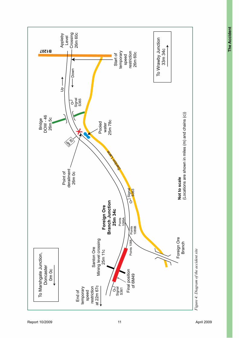
Report 10/2009 5 April 2009
Introduction
Preface1 The sole purpose of a Rail Accident Investigation Branch (RAIB) investigation is
to prevent future accidents and incidents and improve railway safety.2 The RAIB does not establish blame, liability or carry out prosecutions.
Key definitions3 Appendices at the rear of this report contain the following glossaries:
l acronyms and abbreviations are explained in Appendix A;l technical terms (shown in italics the first time they appear in the report) are
explained in Appendix B; andl key standards current at the time of the accident are listed in Appendix C.
4 References to left and right are made in relation to the direction of travel.5 All mileages in this report are measured from the zero point at Marshgate
Junction, Doncaster.
Intr
oduc
tion

Report 10/2009 6 April 2009
Figure 1: Extract from Ordnance Survey map showing location of accident
Summary of the report
Key facts about the accident6 At about 10:48 hrs on Friday 25 January 2008, the tenth wagon of freight train
6M49, the 09:02 hrs service from Immingham Docks to Rugeley Power Station, derailed on plain line at Santon (Figure 1), which is on the double track section of railway line between Wrawby Junction and Foreign Ore Branch Junction, Scunthorpe. The wagon, number 370 157, was loaded with coal.
7 During the derailment, all wheels of the wagon’s leading bogie left the rails and the train continued for just over a mile before stopping. No one was injured in this accident. However, there was considerable damage to the railway infrastructure resulting in the closure of the line for over a week.
Immediate cause, causal and contributory factors, underlying causes8 The immediate cause of the derailment was that the front right-hand wheel flange
of the leading bogie of the tenth wagon climbed the gauge face of the six-foot (high) rail as the train traversed a left-hand curve on the railway line at Santon.
Summ
ary of the report
Location of accident
© Crown Copyright. All rights reserved. Department for Transport 100020237 2009. RAIB
SCUNTHORPE

Report 10/2009 7 April 2009
9 Causal factors were:l the combined effect of two types of track geometry fault: a dynamic 3-metre
track twist and lateral alignment irregularities;l the local Network Rail inspection and maintenance regime did not detect and
repair these faults; andl previous action by the local maintenance staff did not prevent these faults,
which had been detected by the track geometry recording run in November 2007, from quickly appearing again.
10 Probable causal factors were:l the wagon’s wheel was unloaded because the load in the wagon was offset to
one side;l the wheel was also unloaded because of excessive cant in the track;l the local Network Rail inspection and maintenance regime did not repair the
excessive cant; andl the track geometry was deteriorating rapidly because of water in the trackbed.
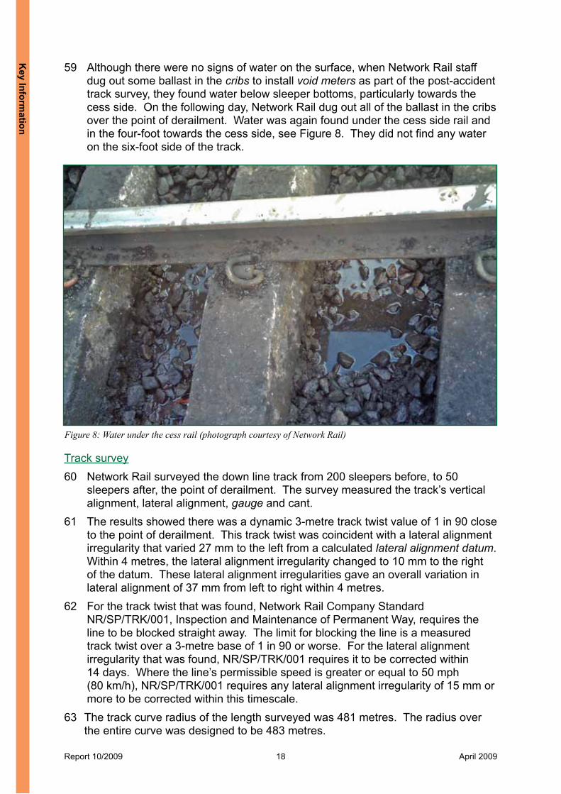
11 Contributory factors were:l the track geometry faults were detected by the last track geometry recording
run, but appeared again after the maintenance action to repair them. These faults then went unnoticed because none of the elements of the inspection regime measured the track twist or lateral alignment over the point of derailment;
l the excessive cant went unnoticed, because none of the elements of the inspection regime measured the cant on the approach to, or over, the point of derailment;
l the local Network Rail maintenance team did not carry out any work which might have corrected or prevented the track twist that recurred;
l there was no planned heavy maintenance or renewal work in this area, that might have addressed the track twist or lateral alignment faults;
l Network Rail did not identify the rapid deterioration in track geometry; andl no one appreciated, reported or responded to the signs of water and poor
drainage in the vicinity of the point of derailment.12 A probable contributory factor was:
l the level of heavy freight traffic over the track at the point of derailment.13 Underlying causes were:
l the temporary loss of information within the local maintenance organisation as a result of many changes to local management roles in a short period; and
l the lack of clear guidance in Network Rail’s track maintenance standard, and its supporting documents, on identifying excessive cant and the actions to be taken or the timescales for carrying out remedial work to address it.
Sum
mar
y of
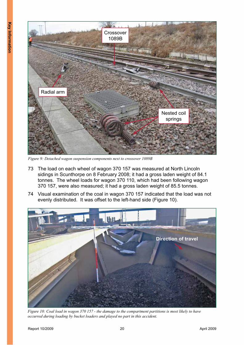
the
repo
rt

Report 10/2009 8 April 2009
Severity of consequences 14 Around 1400 metres of track, including a crossover and a set of switches at
Foreign Ore Branch Junction, required repair or replacement. Lineside signalling equipment and cabling required replacement and a level crossing was damaged. The repair work took nine days to complete and the railway line reopened on 4 February 2008.
15 The derailed wagon suffered significant damage to its leading bogie. The unaffected parts of train 6M49 remained on the track but the derailed wagon ran foul of the other line. A train travelling in the opposite direction could have collided with this wagon, with the possibility of more severe consequences.
Recommendations 16 Recommendations can be found in paragraph 231. They relate to the following
areas:l providing further guidance in the Network Rail standards and supporting
documents on measures to be taken when particular track geometry faults are found close to each other;
l addressing the water underneath the trackbed at Santon and informing track inspection and maintenance staff about the significance of water close to, or within, the trackbed;
l tools to analyse track recording data and improved information for track inspection and maintenance staff to spot trends in track quality, especially rapid deterioration;
l improving the accuracy of location information for track geometry faults;l investigating and monitoring how effectively repeat track geometry faults are
repaired; andl assessing how much the load in a bogie hopper wagon can be permitted to be
offset.
Summ
ary of the report

Report 10/2009 9 April 2009
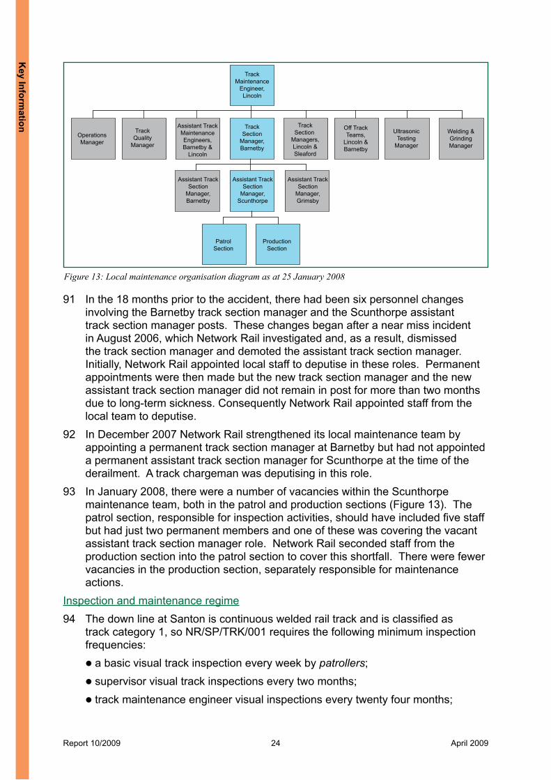
Figure 2: The tenth wagon of 6M49 derailed
The Accident
Summary of the accident 17 At about 10:48 hrs on Friday 25 January 2008, one wagon of freight train 6M49,
the 09:02 hrs service from Immingham Docks to Rugeley Power Station, derailed on plain line at Santon, between Wrawby Junction and Foreign Ore Branch Junction, Scunthorpe.
18 The train was travelling at about 25 mph (40 km/h). During the derailment, all wheels of the leading bogie of the tenth wagon from the locomotive left the rails (Figure 2). The train travelled for just over a mile before the driver became aware of the derailment and brought it to a stop.
19 No one was injured in this accident. The derailed wagon suffered damage to its leading bogie, and about 1400 metres of track, including two sets of switches, signalling equipment and a level crossing, required repair or replacement.
20 The derailed wagon deviated to the right and ran derailed foul of the up line. A train travelling in the opposite direction on the up line could have collided with this wagon, with the possibility of more severe consequences.
The
Acc
iden
t

Report 10/2009 10 April 2009
Figure 3: General view of the curve at Santon close to milepost 26
The parties involved 21 Freightliner Group Limited operated the train, employed the driver and maintained
the locomotive and wagons.22 Greenbrier manufactured the wagons in Poland and Porterbrook owned them.
Axiom Rail holds the design rights for their bogies. 23 An agent, Oxbow Coal Ltd, loaded the wagons on behalf of Associated British
Ports at Immingham Docks.24 Network Rail owned and maintained the track on which the derailment happened.25 Network Rail, Freightliner, Associated British Ports, Oxbow Coal Ltd and Axiom
Rail freely co-operated with the investigation.
Location 26 The derailment occurred on the down line between Wrawby Junction and
Marshgate Junction, Doncaster. 27 The train was travelling towards Doncaster when it derailed at 26 miles 0 chains.
At this point the railway passes through a cutting with a steep cutting slope next to the down line; the track curves to the left on a rising gradient. Local Network Rail staff refer to this location as Santon. A general view of the track at Santon is shown in Figure 3 and a diagram of the accident site is shown in Figure 4.
28 The railway at Santon is signalled using track circuit block and colour light signals and is controlled from Scunthorpe Signal Box.
The Accident
Report 10/2009 11 April 2009
To W
raw
by J
unct
ion
33m
34c
To M
arsh
gate
Jun
ctio
n,D
onca
ster
0m 0
c
Sant
on L
ane
MP 26
X
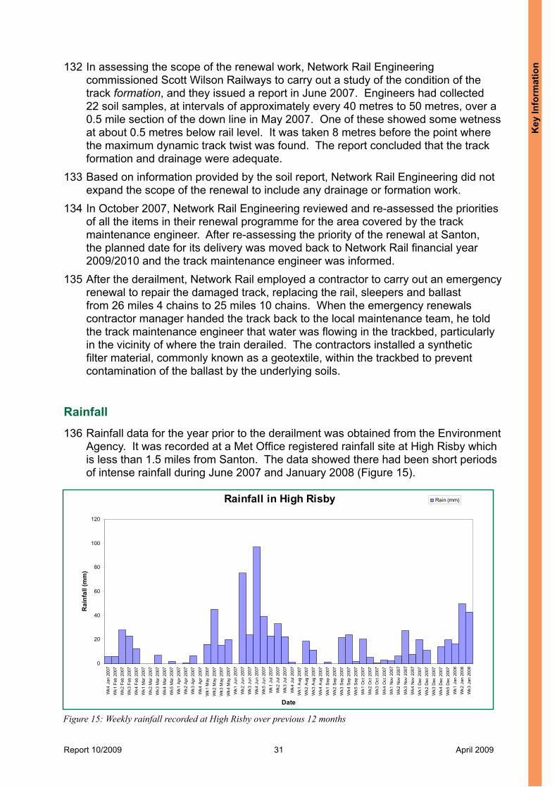
Poi
nts
1088
Poi
nts
1089
BPoi
nts
1089
A
Fore
ign
Ore
Bra
nch
Sig
nal
S36
3
Poo
led
wat
er25
m 7
8c
Poi
nt o
fde
railm
ent
26m
0c
Fore
ign
Ore
Bra
nch
Junc
tion
25m
34c
San
ton
Ore
Min
ing
leve
l cro
ssin
g25
m 1
1c
App
leby
Leve
lC
ross
ing
26m
60c
Sig
nal
S36
5
Up
Dow
n
Brid
geD
OW
- 46
26m
5c
Sta
rt of
tem
pora
rysp
eed
rest
rictio
n26
m 6
0c
Sig
nal
S36
1
Fina
l pos
ition
of 6
M49
Not
to s
cale
(Loc
atio
ns a
re s
how
n in
mile
s (m
) and
cha
ins
(c))
End
of
tem
pora
rysp
eed
rest
rictio
nat
22m
67c
B1207
Figu
re 4
: Dia
gram
of t
he a
ccid
ent s
ite
The
Acc
iden
t

Report 10/2009 12 April 2009
TF25 Bogie Discharge chutesfor each compartment
Radial arm
4 Hopper compartments
Screwcoupling
Figure 5: An HHA wagon
External circumstances 29 The weather at the time of the accident was dry and partly cloudy.
The train 30 The train consisted of diesel-electric locomotive 66 507 and 18 type HHA 4-axle
bogie hopper wagons, coupled with screw couplings. The wagons were carrying coal and the derailed wagon number was 370 157.
31 HHA wagons have a rigid steel underframe with a welded steel hopper mounted on it. The buffer beams and drawgear are also mounted on the underframe. The hopper is divided into four compartments. Coal is loaded into the top of the hopper and is unloaded through four discharge chutes extending below the floor level. Two TF25 bogies carry the wagon. A diagram of an HHA wagon is shown in Figure 5.
32 The HHA wagon weighs about 28 tonnes in its unloaded condition. It has a carrying capacity of 74 tonnes of coal giving a maximum gross laden weight of about 102 tonnes. Its maximum permitted operating speed is 75 mph (121 km/h) when unladen, and 60 mph (97 km/h) when laden.
33 Railtrack gave approval for this wagon type to run on their infrastructure in 2000.
The track 34 At the derailment site, the track consisted of continuous welded 113 A flat-bottom
rails, supported on concrete F27 sleepers and granite ballast. 35 The permissible speed on the down line at this point is 55 mph (89 km/h),
although at the time there was a temporary speed restriction of 40 mph (64 km/h) for passenger trains and 30 mph (48 km/h) for freight trains in force, because of the presence of cyclic top. The start of this temporary speed restriction was just after Appleby level crossing at 26 miles 60 chains and it ended on the approach to Scunthorpe station at 22 miles 67 chains.
The Accident
Report 10/2009 13 April 2009
Events preceding the accident 36 On the morning of 25 January, train 6M49 was loaded with coal at Immingham
Docks, in storage siding number A2, using a loading machine with a bucket (bucket loader) working off a large concrete loading pad alongside the siding.
37 The pre-departure checks (paragraphs 142 to 145) were undertaken and train 6M49 departed at approximately 10:20 hrs. It was running almost 80 minutes late.
Events during the accident 38 At 10:45 hrs, train 6M49 passed over Appleby level crossing at 30 mph (48 km/h).
The driver kept the locomotive throttle in maximum power on the climb to the summit at Foreign Ore Branch Junction. By bridge DOW-46 (at 26 miles 5 chains), the train’s speed had fallen to 27 mph (43 km/h).
39 Close to milepost 26, the driver felt a slight sideways sway on the locomotive but did not think this was unusual. The train’s speed was 26 mph (42 km/h).
40 During the ascent, the driver noticed that the train’s speed was falling more quickly than normal, and on passing the junction at the summit, that the speed was not increasing as expected. These were his first indications that something was wrong since the train’s screw couplings and air and brake pipe connections had remained intact and there was no loss of brake pipe continuity to cause the brakes to apply automatically.
41 Rounding the right-hand curve after the junction, the driver looked back from the right-hand cab window. He saw clouds of dust from half way along the train and immediately applied the emergency brakes. The train stopped approximately 105 metres further on, 100 metres before signal S361.
Consequences of the accident 42 No one was injured in this accident. 43 The derailed wagon suffered significant damage to its leading bogie. The
unaffected parts of train 6M49 remained on the down line. 44 The derailed bogie damaged about 1400 metres of track, including a crossover
and a set of switches at Foreign Ore Branch Junction. It also damaged lineside signalling equipment in the four-foot and Santon Ore Mining level crossing at 25 miles 11 chains.
The
Acc
iden
t
Report 10/2009 14 April 2009
Events following the accident 45 The driver contacted the signaller from the signal post telephone at signal number
S361. The driver asked the signaller to block both the up and down lines to train movements. Once the signaller had done this, the driver walked back along the down line to signal number S365, which was the first signal before the start of the damaged track. The driver placed three detonators on the down line by this signal and told the signaller what he had done. The driver’s actions were not in accordance with module M1 of the Rule Book but did not affect the consequences.
46 He then went back to his train and secured it by applying the handbrakes on the wagons either side of the derailed wagon. He walked back to the locomotive and again contacted the signaller to tell him what he had done.
47 The driver’s employer tested him for drugs and alcohol in accordance with normal industry practice; the results were negative.
48 The site investigation and recovery of the train continued through 25 January to completion on 26 January. Network Rail completed the track repairs on 3 February and the line from Scunthorpe to Barnetby reopened to traffic on 4 February.
The Accident

Report 10/2009 15 April 2009
The Investigation
Investigation process49 The RAIB:
l established the track’s condition, reviewed its inspection and maintenance regime and reviewed the planned work at this location;
l examined the wagon’s operation, established its condition, reviewed its maintenance and observed the process followed for loading it; and
l commissioned dynamic modelling of the wheel / rail interface, to determine the factors that exerted the most influence on the derailment mechanism.
50 The following sources of evidence were used as part of the investigation:l the locomotive’s On Train Data Recorder (OTDR);l examination of the track and locality;l site track survey and previous track recording data;l examination of the derailed wagon;l wheel weighing and data recorded by WheelChex;l observation of the coal loading procedure at Immingham Docks;l VAMPIRE® (Vehicle Dynamic Modelling Package in Railway Environment)
modelling;l rainfall data;l witness testimony; andl information, photographs and documents provided by Freightliner and Network
Rail.
The
Inve
stig
atio
n

Report 10/2009 16 April 2009
Figure 6: Pressure marks and flange climb mark on the railhead looking in the direction of travel
Pressure marks on gauge face
Flange climb markon railhead
Key Information
Derailment marks51 Marks on the railhead showed that a wheel flange had climbed onto the six‑foot
railhead at 26 miles 13 yards. The exact point where it started to climb was not clear, as over a distance of about 2 metres, there were many pressure marks on the gauge face, see Figure 6. These marks indicated that other wheels had begun to climb.
52 The flange mark showed the wheel ran on the railhead for approximately 6.8 metres, before dropping in to the six-foot and running on rail fastenings and sleepers. Corresponding tread corner marks on the cess rail showed the left-hand wheel derailing.
53 Marks on the six-foot railhead about 3.5 metres further on showed a second right‑hand flange climbing, running on the railhead for about 1.5 metres, before dropping to the six-foot side. There was a matching tread corner mark on the cess rail for the left-hand wheel derailing. These corresponded to a trailing wheelset which had been pulled into derailment due to its leading wheelset running derailed.
54 The derailment marks belonged to the two wheelsets of the leading bogie of wagon 370 157 as these were the only ones that derailed. Marks on the track showed the front of the wagon then ran derailed to the right, foul of the up line. These marks included strike marks from the derailed wheelsets on the switch and crossing components at Foreign Ore Branch Junction and on the panels at Santon Ore Mining level crossing.
Key Inform
ation

Report 10/2009 17 April 2009
Figure 7: Water pooled next to the down line’s cess
Track conditionTrack examination55 The track on the down line in the area of the derailment was in a poor condition
with:l seven gauge tie-bars, which were fitted in July 2007, around the curve between
26 miles 2 chains and 25 miles 78 chains, with two of these located about 2 metres and 5.5 metres before the point of derailment (paragraph 128);
l indented concrete sleepers due to galling by the cess rail after the rail pads had worn away;
l missing and broken rail fastenings;l heavy wear and damage to each railhead; andl ballast contaminated by coal dust.
56 There was no grease lubrication around the curve, but neither was the rail showing signs of high friction at the interface to the wheel.
57 There was no ballast shoulder on the cess side, resulting in the sleeper ends being level with the bottom of the cutting slope. There was no cess drain or other man-made drainage installed in this area.
58 Further up the gradient towards Scunthorpe, at around 25 miles 78 chains, a large volume of water was pooled next to the down line cess, see Figure 7. The drains on the adjacent road were blocked and water had breached the side of the road and was collecting in this area.
Key
Info
rmat
ion
Report 10/2009 18 April 2009
Figure 8: Water under the cess rail (photograph courtesy of Network Rail)
59 Although there were no signs of water on the surface, when Network Rail staff dug out some ballast in the cribs to install void meters as part of the post-accident track survey, they found water below sleeper bottoms, particularly towards the cess side. On the following day, Network Rail dug out all of the ballast in the cribs over the point of derailment. Water was again found under the cess side rail and in the four‑foot towards the cess side, see Figure 8. They did not find any water on the six-foot side of the track.
Track survey60 Network Rail surveyed the down line track from 200 sleepers before, to 50
sleepers after, the point of derailment. The survey measured the track’s vertical alignment, lateral alignment, gauge and cant.
61 The results showed there was a dynamic 3-metre track twist value of 1 in 90 close to the point of derailment. This track twist was coincident with a lateral alignment irregularity that varied 27 mm to the left from a calculated lateral alignment datum. Within 4 metres, the lateral alignment irregularity changed to 10 mm to the right of the datum. These lateral alignment irregularities gave an overall variation in lateral alignment of 37 mm from left to right within 4 metres.
62 For the track twist that was found, Network Rail Company Standard NR/SP/TRK/001, Inspection and Maintenance of Permanent Way, requires the line to be blocked straight away. The limit for blocking the line is a measured track twist over a 3-metre base of 1 in 90 or worse. For the lateral alignment irregularity that was found, NR/SP/TRK/001 requires it to be corrected within 14 days. Where the line’s permissible speed is greater or equal to 50 mph (80 km/h), NR/SP/TRK/001 requires any lateral alignment irregularity of 15 mm or more to be corrected within this timescale.
63 The track curve radius of the length surveyed was 481 metres. The radius over the entire curve was designed to be 483 metres.
Key Inform
ation

Report 10/2009 19 April 2009
64 The widest static gauge reading was 1456 mm. Gauge measurements at 35 sleepers were equal to or greater than 1450 mm, which is the maintenance limit as defined in NR/SP/TRK/001 for a line with a permissible speed between 25 mph (40 km/h) and 60 mph (97 km/h).
65 The measured cant was excessive for the curvature and line speed, both before and through the point of derailment. The cant was generally greater than 150 mm, with a maximum reading of 178 mm; the maximum permissible cant in normal circumstances is 150 mm (paragraph 167). The local Network Rail maintenance staff did not know what the installed cant should be but believed the curve was over-canted due to it being designed and installed for an increased permissible speed of 70 mph (113 km/h) which had never been implemented. There were no markings on the sleepers, or plates clipped to the rail web or affixed to nearby structures, to advise what the installed cant should be.
66 The gradient over the length of track surveyed was 1 in 93. The average gradient from Appleby level crossing, at 26 miles 60 chains, to the summit at Foreign Ore Branch Junction, at 25 miles 34 chains, is 1 in 95.
Wagon conditionWagon maintenance67 There was no indication of any relevant outstanding maintenance action on
wagon 370 157. It underwent its last three-monthly maintenance examination on 28 November 2007.
68 The date of the last annual examination was marked on the side of the wagon as 8 March 2007. Freightliner confirmed that this examination took place but could not provide a copy of the record for it, as it was lost when responsibility for HHA wagon maintenance passed from a previous maintainer, Marcroft Engineering, back to Freightliner.
Wagon examination69 The RAIB examined the wagons at North Lincoln sidings in Scunthorpe, and later
at Freightliner’s depot at Midland Road, Leeds.70 The profiles of each wheel on wagon 370 157 and the wagons that had been
either side of it were all within specification for flange height and thickness. The distances between the backs of the flanges on each wheelset were all within specification.
71 Wagon 370 157’s body frame was not twisted and the rear bogie frame had a twist of 6 mm. The front bogie frame, that had sustained damaged when it ran derailed, had a twist of 23 mm over its length of about 2.5 metres. The direction of this twist would, had it existed prior to the accident, have increased load on the leading right-hand wheel.
72 The radial arm for the trailing left-hand wheel was detached from the front bogie. On site, this radial arm and the nested coil springs for the trailing left-hand wheel were lying in the cess close to trailing crossover 1089B at Foreign Ore Branch Junction, see Figure 9. The two huck bolts that attach the radial arm to the bogie frame were found 176 metres and 232 metres after the crossover. There was no evidence on site or from the post-accident examinations of wagon 370 157 to suggest that there were any pre-existing suspension faults.
Key
Info
rmat
ion
Report 10/2009 20 April 2009
Figure 9: Detached wagon suspension components next to crossover 1089B
Crossover 1089B
Nested coil springs
Radial arm
Figure 10: Coal load in wagon 370 157 - the damage to the compartment partitions is most likely to have occurred during loading by bucket loaders and played no part in this accident.
Direction of travel
73 The load on each wheel of wagon 370 157 was measured at North Lincoln sidings in Scunthorpe on 8 February 2008; it had a gross laden weight of 84.1 tonnes. The wheel loads for wagon 370 110, which had been following wagon 370 157, were also measured; it had a gross laden weight of 85.5 tonnes.
74 Visual examination of the coal in wagon 370 157 indicated that the load was not evenly distributed. It was offset to the left-hand side (Figure 10).
Key Inform
ation

Report 10/2009 21 April 2009
Wagon 370157
Figure 11: Wheelchex uneven wheel loads report for train 6M49
75 The coal mostly consisted of very small pieces and dust. It was very wet and water was dripping out from underneath the wagon. Coal slurry was streaked down the right-hand side of the wagon.
WheelChex76 WheelChex is a type of Wheel Impact Load Detector (WILD) system. Both rails
on a section of straight and level track are instrumented and measure the load imparted by a moving wheel. The primary function of WheelChex is to identify vehicles with wheels that are generating excessive dynamic loads on the railhead, such as wheels that have flat spots or are out‑of‑round, so these vehicles can be stopped before they damage the infrastructure. WheelChex can also provide an uneven wheel loads report, which indicates the degree of imbalance between the left and right wheel loads. However, this report is currently not used by Network Rail (the RAIB’s reports into the derailment of a coal train at King Edward’s Bridge, Newcastle, report number 02/2008, and the derailment of a freight train at Ely, report number 02/2009, provide further details1).
77 At 10:30 hrs on 25 January, train 6M49 passed over Network Rail’s WheelChex monitoring site at Croxton, on the down goods line between Immingham and Wrawby Junction. Figure 11 shows the uneven wheel loads report for train 6M49.
1 All RAIB reports are available at the RAIB website, www.raib.gov.uk
Key
Info
rmat
ion

Report 10/2009 22 April 2009
78 Wagon 370 157 (denoted as axles 43 to 46) is highlighted. All of the axles for the HHA wagons show an imbalance to the left-hand side of the train whereas the locomotive (denoted as axles 1 to 6) does not. The RAIB used the static wheel load measurements from undamaged wagon 370 110 (paragraph 73) to corroborate the dynamic weight measurements from WheelChex. The two sets of wheel load measurements were all within 6.5% of each other. The WheelChex measurements were further corroborated by comparing the gross laden weights of 15 other wagons from train 6M49 against those recorded at Rugeley Power Station before being discharged. The two set of measurements were all within 1% of each other.
79 Using the data provided by WheelChex, the RAIB calculated that the load in wagon 370 157 was offset 57% to the left and 43% to the right. It was also calculated to be slightly offset to the rear in the direction of travel; 51% to the rear and 49% to the front.
Dynamic modelling80 Site evidence showed that the mechanism for the derailment was a flange climb
of the right leading wheel of wagon 370 157 (paragraphs 51 to 54). There is a risk of derailment when the ratio of the lateral force of wheel on rail (Y) to the vertical wheel load (Q) exceeds a critical limit value for a sustained distance; therefore the ratio of Y to Q force was calculated using a sliding mean over a two metre length of track, as defined in Railway Group Standard GM/RT2141, Resistance of Railway Vehicles to Derailment and Roll-Over.
81 The critical limit value is dependent on the level of friction between the wheel and rail, and the contact angle. The higher the friction (and the lower the contact angle) between the rail and the wheel flange, the lower the critical limit value becomes.
82 Many factors affect either the Y force or the Q force acting on the wheel-rail interface. In order to reach a more definite understanding of the key factors and their significance to the derailment, two phases of dynamic modelling were undertaken using the VAMPIRE® computer simulation package. The track model was created using data from the track survey and Axiom Rail provided a newly created vehicle model, as the original used for the HHA wagon’s vehicle acceptance could not be found. Axiom Rail validated this new model against practical test results recorded when the HHA wagon underwent its vehicle acceptance. The RAIB then reviewed this validation work before the dynamic modelling took place.
83 In the first phase of modelling work, the RAIB assessed the factors that would most likely effect the Y or Q forces acting on the wheel. The following factors were considered:l speed;l track twist;l lateral alignment irregularities;l track cant;l distribution of load in the wagon; andl wheel‑rail friction and the profiles of the wheels and rails.
Key Inform
ation

Report 10/2009 23 April 2009
Figure 12: Tonnage on the down line over the past 6 years
Tonnage over DOW2100
3000.00
1000.00
1500.00
2000.00
2500.00
2000/01 P1
2001/02 P1
2002/03 P1
2003/04 P1
2004/05 P1
2005/06 P1
2006/07 P1
2007/08 P1
Period
Tonn
es Total tonnesTrend line
Tonnage over Down line
Network Rail Period
Tonn
es (0
00’s
)84 The modelling took place with each factor varied in turn to determine its influence.
The simulations considered speeds of 5 mph (8 km/h), 25mph (40 km/h) and 30 mph (48 km/h).
85 The second phase of modelling work concentrated on the combined influences of speed, track twist, and lateral alignment. This work used a revised track model that incorporated scaled data from the last track geometry recording run to give an improved representation of the lateral alignment.
86 The track twist and lateral alignment were incrementally varied to determine their influence on the Y and Q forces acting on the leading right‑hand wheel. Wagon speeds of 25 mph (40 km/h), 30 mph (48 km/h) and 33 mph (53 km/h) were considered.
87 The findings of the modelling work are explained in paragraphs 154 to 170.
Track inspection and maintenanceTonnage and track category88 Over the past six years there has been a 38% increase in the annual tonnage
carried over this line, see Figure 12.
89 In terms of tonnage, this line is one of the most heavily used on Network Rail. As a result, it is classified according to NR/SP/TRK/001 as track category 1 between 25 miles 35 chains and 33 miles 24 chains. The track category is set by the Network Rail territory engineer (track); it is re-assessed every six months.
Local maintenance organisation90 Network Rail’s maintenance team based at Scunthorpe are responsible for
inspecting and maintaining the down line where the derailment happened. The local maintenance organisation is shown in Figure 13.
Key
Info
rmat
ion
Report 10/2009 24 April 2009
OperationsManager
TrackMaintenance
Engineer,Lincoln
TrackSection
Manager,Barnetby
TrackSection
Managers,Lincoln &Sleaford
Off TrackTeams,
Lincoln &Barnetby
UltrasonicTesting
Manager
Assistant TrackMaintenanceEngineers,Barnetby &
Lincoln
TrackQuality
Manager
Welding &GrindingManager
Assistant TrackSection
Manager,Scunthorpe
Assistant TrackSection
Manager,Barnetby
Assistant TrackSection
Manager,Grimsby
PatrolSection
ProductionSection
Figure 13: Local maintenance organisation diagram as at 25 January 2008
91 In the 18 months prior to the accident, there had been six personnel changes involving the Barnetby track section manager and the Scunthorpe assistant track section manager posts. These changes began after a near miss incident in August 2006, which Network Rail investigated and, as a result, dismissed the track section manager and demoted the assistant track section manager. Initially, Network Rail appointed local staff to deputise in these roles. Permanent appointments were then made but the new track section manager and the new assistant track section manager did not remain in post for more than two months due to long-term sickness. Consequently Network Rail appointed staff from the local team to deputise.
92 In December 2007 Network Rail strengthened its local maintenance team by appointing a permanent track section manager at Barnetby but had not appointed a permanent assistant track section manager for Scunthorpe at the time of the derailment. A track chargeman was deputising in this role.
93 In January 2008, there were a number of vacancies within the Scunthorpe maintenance team, both in the patrol and production sections (Figure 13). The patrol section, responsible for inspection activities, should have included five staff but had just two permanent members and one of these was covering the vacant assistant track section manager role. Network Rail seconded staff from the production section into the patrol section to cover this shortfall. There were fewer vacancies in the production section, separately responsible for maintenance actions.
Inspection and maintenance regime94 The down line at Santon is continuous welded rail track and is classified as
track category 1, so NR/SP/TRK/001 requires the following minimum inspection frequencies:l a basic visual track inspection every week by patrollers;l supervisor visual track inspections every two months; l track maintenance engineer visual inspections every twenty four months;
Key Inform
ation

Report 10/2009 25 April 2009
l supervisor and track maintenance engineer cab rides every two and three months respectively; and
l track geometry recording runs every three months.95 The maintenance regime addresses the items that are reported as part of the
inspection regime. The assistant track section manager gives each item a priority and it is then entered as a work order on Ellipse. Ellipse is Network Rail’s system for managing maintenance tasks: primarily a work bank which lists all of the inspection and maintenance tasks to be done.
Basic visual inspections96 As stated by NR/SP/TRK/001, patrollers carry out basic visual inspections to
‘identify defects which, if uncorrected, could affect the safety or reliable operation of the railway before the next inspection’. The basic visual inspection walk at Santon was from 25 miles 30 chains to 26 miles 30 chains and patrolling records for the previous six months show that these walks were taking place every six to eight days. As allowed by NR/SP/TRK/001, the patroller walked along the up and down lines on alternate weeks, with both lines being visually examined at the same time. The direction in which the line was walked varied.
97 The sighting distances at Santon are limited because of the curvature of the track, and the railway also passes through a cutting with limited clearance, so Network Rail classifies this area as one where work cannot be carried out safely if trains are running. All of the patrols took place with protection arrangements that meant no trains were running on the line being walked along, limiting the opportunities for patrollers to observe the track on the down line with traffic on it. When patrollers walked along the up line, it would have been difficult to see voiding under the far cess rail when a train passed by on the down line.
98 A patroller walked along the up line on the day before the accident while the last patrol along the down line was six days before that. The patroller did not raise any new faults or comments about the condition of the track afterwards. Nine patrols over the previous six months, including the previous two patrols during January 2008, had reported problems with the vertical alignment of the cess rail on the down line within 80 metres of the point of derailment. Patrollers had also identified problems with dips in the cess rail in the months before the derailment. The patrollers did not measure the vertical alignment (paragraph 176). None of the weekly visual inspections reported the track twist, the lateral alignment irregularities or the excessive cant.
99 The assistant track section manager had signed off each patrol report to show he had planned repair work to address the vertical alignment problems. Each problem was then entered on Ellipse as a work order. However, the production section did not do any of this work before the derailment because either:l the planned date on the work order, as set by the assistant track section
manager, was after the accident; orl the work order was reprioritised at a Network Rail planning meeting, based on a
report submitted by the track quality manager, so its revised planned date was after the accident; or
l the work order was cancelled at a Network Rail planning meeting because the attendees thought it had already taken place.
Key
Info
rmat
ion

Report 10/2009 26 April 2009
Supervisor inspections100 Over the preceding six months, the supervisor visual track inspections were
taking place every eight weeks, for the walk from 23 miles 0 chains to 28 miles 0 chains which included Santon. This inspection has two main aims: to review and decide upon the actions necessary to respond to the reports raised by patrollers, and to measure track twist and gauge, at intervals along the track. The supervisor chooses where to take measurements based upon the track condition, taking into account traces from track geometry recording runs and reports from basic visual inspections.
101 The track section manager carried out the last supervisor visual inspection at Santon twelve days before the accident. During this inspection, he did not refer to the trace from the last track geometry recording run. He measured the gauge over the point of derailment but did not measure the track twist or cant. Neither this inspection, nor any of the previous supervisor visual inspections identified any track twist or lateral alignment faults at the derailment site, or the excessive cant around the curve.
102 During the last supervisor inspection, the track section manager had recognised that the vertical alignment on the down line in the area of the derailment was poor and modified a work order to extend the mileage for planned tamping work at Santon. The track section manager was aware that the curve was over-canted but did not appreciate how much it exceeded its allowable maximum value. The track section manager then made verbal arrangements to redirect tamping resources to do this work within two weeks. The track quality manager scheduled the tamping for the night of 26-27 January 2008 and also prepared a plan for the tamping that would have reduced the amount of cant.
Track maintenance engineer inspections103 The track maintenance engineer has a rolling programme to see, on foot, all of
the railway track within his responsibility every two years. The aim of the track maintenance engineer’s inspection is to check the performance of those carrying out the other visual inspections and to identify any longer term items with the potential to affect the safety of the railway.
104 The last track maintenance engineer visual inspection around Santon was in July 2007 and was delegated to the Barnetby assistant track maintenance engineer. This inspection identified significant problems with gauge widening that led to the down line being blocked to traffic. This inspection did not identify any track twist or lateral alignment problems.
105 The maintenance team installed twelve tie-bars to retain the gauge around the curve before the line reopened. NR/SP/TRK/001 states that tie‑bars may be fitted as a temporary measure, with permanent repairs required within six months at most, so Network Rail began a programme of work to allow these tie-bars to be removed (paragraphs 124 to 129).
Supervisor and track maintenance engineer cab rides106 The supervisor and track maintenance engineer supplement their inspections by
cab riding. During the six months before the derailment, cab riding was taking place at the required intervals.
Key Inform
ation

Report 10/2009 27 April 2009
107 The last supervisor cab ride was in December 2007 and was delegated to an assistant track section manager as the track section manager role was vacant at the time. The last track maintenance engineer cab ride was in October 2007. Both cab rides generated reports that related to the poor vertical alignment of the track.
108 The last supervisor and track maintenance engineer cab ride reports both recommended that tamping should take place over the point of derailment to correct the vertical alignment. As a result of the supervisor’s report, no-one entered a corresponding work order into Ellipse. As a result of the track maintenance engineer’s report, the assistant track section manager raised a work order on Ellipse for tamping. However, the attendees at a weekly planning meeting later cancelled it as they mistakenly thought that the track had been already been recently tamped at this point.
Track geometry recording runs109 As required by NR/SP/TRK/001, track geometry recording runs on the down line
were taking place approximately every three months. The track recording unit collects the data which allows Network Rail to monitor the overall quality of the track and to find discrete track geometry faults that require maintenance action. The track recording unit is Network Rail’s primary means of measuring dynamic track twist and lateral alignment on this line.
110 The last track geometry recording run before the derailment was on 14 November 2007. It detected a 1 in 108 track twist and a lateral alignment irregularity of 15 mm at the derailment site. Both of these faults were identified by the track recording unit as discrete track geometry faults. Altogether this track geometry recording run detected eleven discrete track geometry faults in the vicinity of the derailment site, all of which required maintenance action. This run also recorded dynamic cant readings greater than 150 mm, which is the maximum permissible in normal circumstances, for a distance of 6.5 metres on the approach to the derailment site and then for 18.5 metres just before the point of derailment (Figure 16). Cant readings of more than 150 mm are not classified by the track recording unit as track geometry faults that require maintenance action.
111 The previous track recording run was in September 2007 and it detected a 1 in 142 track twist at the derailment site. It also found a lateral alignment irregularity of 12 mm, but this was below the 15 mm threshold for it to be reported as a fault. It also recorded dynamic cant readings greater than 150 mm for 3.75 metres just before the point of derailment and again for 1.75 metres about 14 metres after it (Figure 16). The track recording run before this was in May 2007. This run did not detect any track geometry faults at the derailment site that required action and all dynamic cant readings were between 110 mm and 120 mm, which is the expected amount of cant for this curve
112 Network Rail measure the ride quality of the track with respect to its vertical profile and alignment. It is expressed as a standard deviation value for every eighth of a mile and Network Rail specifies maximum and target standard deviation values in NR/SP/TRK/001. The Network Rail Data Centre produces a chart with the standard deviation values for the last ten track geometry recording runs plotted on it. The chart shows how the standard deviation values have changed over time. Each standard deviation value is colour coded according to which band it falls into to assist with the identification of trends. Figure 14 shows the standard deviation chart covering the point of the derailment. No standard deviation values are produced for track twist or cant.
Key
Info
rmat
ion

Report 10/2009 28 April 2009
Figure 14: The standard deviation chart covering the point of derailment
Down Line: 25 m 0y - 27 m 0 y
Locality of derailment
113 The point of derailment was close to the boundary between the two eighth mile sections at milepost 26. The vertical and lateral alignment standard deviation values for these sections had been steadily increasing since the track geometry recording run in May 2007, moving them from the good band to the satisfactory or poor bands. Neither eighth mile section had reached a target value which would have triggered the local maintenance team to carry out remedial actions to improve the track quality.
114 The local maintenance organisation receives the standard deviation chart but also uses a similar chart produced by a system called Obsidian to monitor changes in track quality. Obsidian was introduced by the local infrastructure maintenance company previously responsible for track maintenance in this area. Obsidian processes the same raw data from the track geometry recording runs to provide a standard deviation chart with a slightly different format.
115 The local maintenance organisation receives a track recording unit trace that is generated following each run. With a scale of one mile per page, this shows graphically how eleven different track geometry parameters vary along the line. The applicable limits for some of the parameters as defined in NR/SP/TRK/001 are also shown on the trace so exceedences can be seen.
Key Inform
ation

Report 10/2009 29 April 2009
116 The track maintenance engineer visually reviews the trace to manually locate each exceedence and decides if it is a new or repeat fault. The track maintenance engineer annotates the trace as part of this review, highlighting repeat faults and directing his staff to look at or provide information about other faults. The trace is then passed to the track section manager, who is expected to refer to this information when carrying out the next supervisor visual track inspection. The track maintenance engineer also logs the number of exceedences in each eighth mile section in a database held locally.
117 The local maintenance team responded to the track geometry faults detected by the track geometry recording runs in September 2007 and November 2007 (paragraphs 110 and 111). The systems on the track recording unit automatically generate an action sheet following each run. The action sheet lists the type of fault, its location, its severity and the time limit for fixing it. These action sheets do not list the locations where the dynamic cant is greater than 150 mm.
118 The local maintenance team signed off each fault on the action sheets from both the September and November runs, with all of the faults repaired within the timescale required by NR/SP/TRK/001.
119 Following the November track geometry recording run, the local maintenance team went to Santon three times to carry out repairs. The first time was on the day of the track geometry recording run to respond to those faults that needed attention within 36 hours, then 4 days later to address the faults with a 14-day time limit and finally a further 12 days later to carry out additional lifting and packing of the track.
120 To correct the track twist faults, a member of the maintenance team took static measurements to confirm the location of the track twist. Once the maintenance team were satisfied that they had found the track twist, they manually lifted and packed the track to remove the track twist. A maintenance team member took a static track twist measurement afterwards to confirm its removal. Dynamic track twist was not measured. The person in charge of the maintenance work then signed off the track twist fault on the action sheet, but did not record the details of the method of repair or the static measurements taken both before and after the repair.
121 To correct the lateral alignment irregularity, a manual repair took place, as a tamping machine was not available. The maintenance team confirmed the location of the fault by eye. The repair work involved lifting the track with jacks and manually moving it laterally to the correct position. The staff in the production section did not measure the lateral alignment either before or after this repair work. The person in charge of the maintenance work then signed off this fault on the action sheet.
122 The person in charge of the maintenance work signed and dated the action sheet underneath the list of faults once all of them had been repaired. No further work took place. There was no monitoring afterwards to determine if the repair work was effective and permanent.
123 The track maintenance engineer highlighted the excessive cant on the track geometry recording run trace. However, there is no record of any repair work being carried out to reduce the amount of cant.
Key
Info
rmat
ion

Report 10/2009 30 April 2009
Heavy maintenance work124 Network Rail identified that the gauge widening found during the last track
maintenance engineer visual inspection was caused by galling of concrete sleepers which was resulting in the rail rolling over. NR/SP/TRK/001 allows the fitment of gauge tie‑bars as a temporary measure to maintain gauge, with permanent repair required within six months.
125 To carry out a permanent repair within this timescale, the track maintenance engineer sought and gained additional budget to carry out a programme of heavy maintenance work to replace these sleepers and improve the track’s vertical alignment. By the time of the derailment, 42 concrete sleepers between 25 miles 78 chains and 26 miles 0 chains had been changed over two weekends: 13-14 October and 10-11 November 2007. Further work was planned (paragraph 128).
126 The maintenance staff who replaced the sleepers had dug the ballast out to a depth of 200 mm. They described seeing standing water in the trackbed. At the time, no-one reported this to the track maintenance engineer.
127 On the Monday morning after the work done on 10-11 November 2007, a train driver reported a very rough ride. The signaller blocked the down line to traffic at Santon after the following train confirmed it. The line reopened after the maintenance team had lifted and packed the track over the newly installed sleepers. Network Rail’s investigation concluded that there had been poor track settlement due to the maintenance staff not consolidating the ballast below the underside of the sleepers, and then very low overnight temperatures.
128 New sleepers had been installed to within 4 sleepers of where the maximum dynamic track twist was found. Seven gauge tie-bars were still in place so Network Rail had planned to do further sleeper replacement work, that would have covered the area of the track twist, in February 2008.
129 In January 2008 the Barnetby assistant track maintenance engineer sought and obtained a temporary dispensation from the area track engineer for these gauge tie-bars to be installed for longer than the six month time limit.
Renewals130 Due to signs of wear, Network Rail maintenance submitted a proposal in October
2005 for the renewal of the rail, sleepers and ballast on the down line in the Santon area. The proposal was passed to Network Rail Engineering who are responsible for the assessment, funding and implementation of renewals.
131 Network Rail Engineering organised an inspection at Santon in July 2006 and, after assessing the need for the renewal, it agreed to support it. Network Rail Engineering set a provisional date for the renewal to happen in Network Rail financial year 2008/2009, based on the findings of the site inspection and the amount of other renewal work already planned to take place in this region. The proposed renewal date was agreed with the track maintenance engineer and the area track engineer.
Key Inform
ation
Report 10/2009 31 April 2009
132 In assessing the scope of the renewal work, Network Rail Engineering commissioned Scott Wilson Railways to carry out a study of the condition of the track formation, and they issued a report in June 2007. Engineers had collected 22 soil samples, at intervals of approximately every 40 metres to 50 metres, over a 0.5 mile section of the down line in May 2007. One of these showed some wetness at about 0.5 metres below rail level. It was taken 8 metres before the point where the maximum dynamic track twist was found. The report concluded that the track formation and drainage were adequate.
133 Based on information provided by the soil report, Network Rail Engineering did not expand the scope of the renewal to include any drainage or formation work.
134 In October 2007, Network Rail Engineering reviewed and re-assessed the priorities of all the items in their renewal programme for the area covered by the track maintenance engineer. After re-assessing the priority of the renewal at Santon, the planned date for its delivery was moved back to Network Rail financial year 2009/2010 and the track maintenance engineer was informed.
135 After the derailment, Network Rail employed a contractor to carry out an emergency renewal to repair the damaged track, replacing the rail, sleepers and ballast from 26 miles 4 chains to 25 miles 10 chains. When the emergency renewals contractor manager handed the track back to the local maintenance team, he told the track maintenance engineer that water was flowing in the trackbed, particularly in the vicinity of where the train derailed. The contractors installed a synthetic filter material, commonly known as a geotextile, within the trackbed to prevent contamination of the ballast by the underlying soils.
Rainfall136 Rainfall data for the year prior to the derailment was obtained from the Environment
Agency. It was recorded at a Met Office registered rainfall site at High Risby which is less than 1.5 miles from Santon. The data showed there had been short periods of intense rainfall during June 2007 and January 2008 (Figure 15).
Figure 15: Weekly rainfall recorded at High Risby over previous 12 months
Rainfall in High Risby
0
20
40
60
80
100
120
Wk4
Jan
200
7W
k1 F
eb 2
007
Wk2
Feb
200
7W
k3 F
eb 2
007
Wk4
Feb
200
7W
k1 M
ar 2
007
Wk2
Mar
200
7W
k3 M
ar 2
007
Wk4
Mar
200
7W
k5 M
ar 2
007
Wk1
Apr
200
7W
k2 A
pr 2
007
Wk3
Apr
200
7
Wk4
Apr
200
7W
k1 M
ay 2
007
Wk2
May
200
7W
k3 M
ay 2
007
Wk4
May
200
7W
k1 J
un 2
007
Wk2
Jun
200
7W
k3 J
un 2
007
Wk4
Jun
200
7W
k5 J
un 2
007
Wk1
Jul
200
7W
k2 J
ul 2
007
Wk3
Jul
200
7
Wk4
Jul
200
7W
k1 A
ug 2
007
Wk2
Aug
200
7W
k3 A
ug 2
007
Wk4
Aug
200
7W
k1 S
ep 2
007
Wk2
Sep
200
7W
k3 S
ep 2
007
Wk4
Sep
200
7W
k5 S
ep 2
007
Wk1
Oct
200
7W
k2 O
ct 2
007
Wk3
Oct
200
7
Wk4
Oct
200
7W
k1 N
ov 2
007
Wk2
Nov
200
7W
k3 N
ov 2
007
Wk4
Nov
200
7W
k1 D
ec 2
007
Wk2
Dec
200
7W
k3 D
ec 2
007
Wk4
Dec
200
7W
k5 D
ec 2
007
Wk1
Jan
200
8W
k2 J
an 2
008
Wk3
Jan
200
8
Date
Rai
nfal
l (m
m)
Rain (mm)
Key
Info
rmat
ion

Report 10/2009 32 April 2009
137 The intense rainfall in June 2007 coincided with Network Rail closing the railway between Santon and Foreign Ore Branch Junction for four days due to flooding.
Wagon loadingLoading process138 Trains are loaded with imported coal at Immingham Docks either by passing
through an automatic loading facility, the Humber International Terminal, or by using bucket loaders working off one of the five loading pads, with the train stabled in an adjacent siding.
139 Oxbow loaded train 6M49 from the concrete loading pad adjacent to storage siding number A2. A bucket loader was used to shovel coal from a stockpile which was then tipped into each wagon in turn. The wagons were loaded only from the right-hand side, as access to the other side is not possible.
140 The bucket when loaded level, holds approximately 14 tonnes of coal. Five bucketfuls are normally put into each wagon, giving an approximate load of 70 tonnes. Wagon 370 157 was loaded with about 57 tonnes, which is about four buckets of coal. The Oxbow loader had reduced the number of buckets of coal loaded to avoid overloading because the coal was wet and therefore heavier. It is normal practice for the loader to reduce the amount of coal loaded when it is wet.
141 Once loading was complete, the Oxbow loader gave the train driver a loading slip and informed the English, Welsh and Scottish Railways (EWS) reception office, which controls train movements within Immingham Docks and the interface with Network Rail infrastructure.
Pre-departure checks142 After loading was finished, the driver commenced his pre‑departure checks. He
did not need to carry out a load examination as described in Railway Group Standard GO/RM3056, Working Manual for Rail Staff Freight Train Operations, for the following reasons. Firstly, at ground level the driver cannot see into the wagons to examine the load. Secondly, the loading pads at Immingham are considered by Freightliner as dangerous areas for personnel on foot, so the amount of time that the driver spends outside the locomotive cab is minimised. Network Rail has published a local amendment to the rules for operating freight trains that gives exemption from these instructions in the local instructions for Immingham Docks.
143 At the start of his shift, the driver collected a form RT3973/HAW ‘Advice to train crews – conveyance of heavy axle weight wagons’. This form provides details of the route and speed restrictions imposed on loaded HHA wagon movements between Immingham and Rugeley Power Station. One such speed restriction was a 30 mph (48 km/h) speed limit when passing over bridge DOW-46 at 26 miles 5 chains on the down line at Santon.
Key Inform
ation

Report 10/2009 33 April 2009
144 After completing his paperwork, the driver contacted the EWS reception office to say that his train was ready to move. An EWS shunter then authorised the driver to proceed over the weighbridge on the exit from the sidings. The weighbridge measured the axle loads of each wagon. Staff from EWS checked that none of the wagons were overloaded but did not check if the load was offset as they are not required to do so. The weighbridge is capable of providing side-to-side load measurements but is not configured to do this.
145 Once satisfied that none of the wagons were overloaded, the consist for train 6M49 was released on TOPS, a computer system used to track rail vehicles, including their destination, load, location and maintenance information. This was the final pre‑departure activity and with the permission of the Network Rail signaller, train 6M49 departed.
Previous occurrences of a similar character146 In the year prior to this derailment, other significant flange climb derailments on
plain line investigated by the RAIB were:l King Edward Bridge, Newcastle upon Tyne (10 May 2007, RAIB report
reference 02/2008) where a track twist, between switches and crossings, combined with a twisted wagon frame to cause a derailment;
l Ely (2 June 2007, RAIB report reference 02/2009) where a track twist contributed to the derailment of a wagon with a twisted frame and high friction forces within its suspension; and
l Duddeston Junction, Birmingham, (10 August 2007, RAIB report reference 16/2008) where the interaction between a combination of track twists, between switches and crossings, and an unevenly loaded wagon caused a derailment.
147 Since this derailment, there has been a flange climb derailment at Moor Street, Birmingham, (25 March 2008, RAIB report reference 07/2009) where a severe track twist caused a freight train to derail.
148 A passenger train derailment occurred at Epsom (12 September 2006, RAIB report reference 34/2007) where poor track geometry, created by the combination of the vertical and lateral misalignment of the track, local rail damage and sidewear, was a causal factor. These defects were apparent from inspection and measurement, and were covered by standards that required action to be taken. Because compliance with these standards would have corrected the conditions, no recommendation was made in respect of track geometry standards.
Key
Info
rmat
ion

Report 10/2009 34 April 2009
149 A freight train derailment occurred on Cricklewood Curve (31 January 2006, RAIB report reference 02/2007). This was caused by severe track twist brought about by movement of an embankment which had the effect of increasing the cant of the track. The track maintenance staff did not understand the significance of the excessive amount of cant, so no remedial work took place to correct it. Two safety recommendations were made in relation to cant: l ‘Recommendation 3: Network Rail should revise NR/SP/TRK/001 to give
guidance on appropriate measures to be taken on discovery of excessive cant with timescales for action.’
l ‘Recommendation 4: Network Rail should revise the track inspection handbook associated with work instruction NR/WI/TRK/001 to refer to the cant deviation limits in NR/SP/TRK/001.’
150 Network Rail rejected Recommendation 3 by arguing that appendix E of NR/SP/TRK/001 already covered the management of cant variations adequately. NR/SP/TRK/001 does not give a definite timescale for rectifying cant variations that exceed the specified maintenance or intervention limits and instead states that the work should be done ‘as quickly as practicable’.
151 Initially Network Rail did not support the change to work instruction NR/WI/TRK/001 as described in Recommendation 4. However, the Office of Rail Regulation were told by Network Rail that this change will now be assessed when NR/WI/TRK/001 is next revised.
152 There have been no other derailments recorded involving HHA wagons on main running lines since their entry into service in 2000.
Key Inform
ation

Report 10/2009 35 April 2009
Analysis
Identification of the immediate cause2 153 Marks on the railhead of the down line showed that the immediate cause of the
derailment was the front right‑hand wheel flange of the leading bogie of wagon 370 157 climbing the gauge face of the six-foot (high) rail as train 6M49 traversed the left-hand curve on the down line at Santon.
Identification of causal3 and contributory4 factors Factors relating to the derailment mechanism154 Flange climb derailments occur when the ratio of the lateral Y force to the vertical
Q force exceeds a critical limit value for a sustained distance, as explained in paragraphs 80 and 81.
155 When the vehicle and track conditions present at the time of the derailment were modelled, the predicted Y and Q forces confirmed that the leading right‑hand wheel of wagon 370 157 was prone to flange climbing at the observed site of derailment. The modelling was used to understand the sensitivity of the Y and Q forces to the key factors identified in paragraph 83.
Track twist and lateral alignment156 A 1 in 90 track twist was found to unload the front right-hand wheel of the leading
bogie of wagon 370 157, reducing the Q force, increasing the risk of flange climb. 157 The modelling showed that at the same point, the first lateral alignment
irregularity caused the leading wheelset’s left flange to press against the gauge face of the left (cess) rail. In response to the second lateral alignment irregularity as measured on site, the modelling showed that the wheelset then moved quickly to the right, within 4 metres, so that the right‑hand flange struck against the gauge face of the right (six-foot) rail. This resulted in a Y force, increasing the risk of flange climb. This lateral movement of the wheelsets was corroborated by the pressure marks found on the gauge face of the six-foot rail (paragraph 51).
158 The modelling showed that there was a complex relationship between the dynamic response of the wagon and the track geometry faults. By increasing the speed from 25 mph (40 km/h) to 30 mph (48 km/h) the propensity to derail increased, but further increasing the speed to 33 mph (53 km/h) then reduced it.
159 Reducing the amplitude of the lateral alignment irregularities reduced the predicted risk of flange climb and moved the predicted point of derailment towards where the maximum track twist was. With smaller lateral alignment irregularities, the derailment risk reduced so significantly it could be seen that the other key factors on their own would not have been sufficient to initiate a flange climb.
2 The condition, event or behaviour that directly resulted in the occurrence.3 Any condition, event or behaviour that was necessary for the occurrence. Avoiding or eliminating any one of these factors would have prevented it happening. 4 Any condition, event or behaviour that affected or sustained the occurrence, or exacerbated the outcome. Eliminating one or more of these factors would not have prevented the occurrence but their presence made it more likely, or changed the outcome.
Ana
lysi
s

Report 10/2009 36 April 2009
160 Reducing the amount of track twist to 1 in 126 (which is the limit in NR/SP/TRK/001 where corrective action is required within 14 days) had little effect on the predicted Y and Q forces. However, with negligible track twist, the derailment risk reduced so significantly it could be seen that the other key factors on their own would not have been sufficient to initiate a flange climb.
161 The modelling showed that the track twist and lateral alignment irregularities were the dominant factors, and the leading right‑hand flange was only prone to climbing when both were present. The combination of the track twist and the lateral alignment irregularities was a causal factor in the derailment.
162 NR/SP/TRK/001 clearly defines what actions maintenance staff must take in response to specific irregularities. However, there is no guidance given on the actions required for combinations of track twist and lateral alignment irregularities. Instead, there is just a general note under table 8 in NR/SP/TRK/001 that states ‘These actions assume no significant associated irregularities. If other irregularities exist the action may need to be more stringent’.
163 Depending upon their amplitude, NR/SP/TRK/001 requires Network Rail to correct track twists immediately, within 36 hours or within 14 days. Network Rail must correct all lateral alignment irregularities that are 15 mm or more within 14 days. There are no other limits in NR/SP/TRK/001, irrespective of the severity of the lateral alignment irregularity, which requires Network Rail to shut the line or take action that is more urgent.
Wagon loading164 The wagon weight measurements showed that none of the wagons were
overloaded, but that their load was unevenly distributed. For wagon 370 157, the load offset to the left caused a lateral offset of the centre of gravity. The wagon’s centre of gravity was also offset slightly to the rear. This reduced the load on the front right-hand wheels of the wagon, reducing the Q force, increasing the risk of flange climb.
165 For this particular amount of load, changing the offset load condition to an evenly distributed load reduced the predicted risk of flange climb. The predicted risk was still at a high level but was not sufficient to cause the leading right‑hand wheel of wagon 370 157 to flange climb. The modelling showed that the offset load is not a dominant factor in the derailment mechanism, but it is likely to be necessary, along with the track twist, lateral alignment irregularities and excessive cant, to cause the derailment. Therefore the wheel unloading due to the coal in the wagon being offset to one side was a probable causal factor to the derailment.
166 Freightliner’s loading procedures and GO/RM3056 both require loads to be distributed as uniformly as possible to ensure all wheels are evenly loaded. However, as all of the coal was loaded from just the right-hand side, the bucket loader tended to tip it into the wagons towards the left-hand side. In addition, the water in the coal meant it tended to stick together so it was more prone to settle to the left-hand side during the loading.
Analysis

Report 10/2009 37 April 2009
Cant167 Network Company Standard NR/SP/TRK/00495, Track Design Handbook, states
that normally the cant should not exceed 150 mm. However, the cant measured at Santon was generally greater than this, despite its expected value being much less (paragraph 111). At the train’s maximum permitted speed of 30 mph (48 km/h), this excessive cant would have reduced the load on the right-hand wheels of the wagon, reducing the Q force, increasing the risk of flange climb.
168 With all of the other track geometry faults present, reducing the cant to its expected value reduced the predicted risk of flange climb. The predicted risk was still at a high level but was not sufficient to cause the leading right‑hand wheel of wagon 370 157 to flange climb. The modelling showed that the excess cant is not a dominant factor in the derailment mechanism, but it is likely to be necessary, along with the track twist, lateral alignment irregularities and offset load, to cause the derailment. Therefore the wheel unloading due to the excess cant on the left-hand curve at Santon was a probable causal factor to the derailment.
Wheel-rail contact conditions169 Based on the railhead conditions seen on site, an average wheel-rail friction
coefficient of 0.32 was assumed. A sensitivity study showed that the effect of lowering or increasing the amount of friction was negligible.
170 The effect of differences between new and as‑measured wheel and rail profiles was also negligible.
Factors relating to the inspection & maintenance of the track171 The Network Rail records for the six months prior to the derailment show that the
track inspection regime was compliant with the requirements of NR/SP/TRK/001. While meeting the minimum basic visual inspection frequencies defined in NR/SP/TRK/001, the visual inspections did not identify the track twist and the lateral alignment irregularities that caused the derailment (paragraph 176).
172 Previous track twist and lateral alignment irregularities had been detected over the point of derailment by track geometry recording runs. Network Rail had immediately carried out repairs, but, despite this the faults had appeared again rapidly by the date of the accident (paragraphs 181 to 186).
173 The local Network Rail inspection and maintenance regime not detecting and repairing the track twist and lateral alignment track geometry faults before the passage of train 6M49 was a causal factor.
174 The previous two track geometry recording runs had measured excessive dynamic cant with values over 150 mm, but NR/SP/TRK/001 does not define excess cant as a track geometry fault that must be raised on the track recording unit action sheet. The track maintenance engineer had annotated the area on the track geometry recording run trace where the cant readings were excessive but no work was planned or carried out to reduce the excessive cant. The local Network Rail inspection and maintenance regime not repairing the excessive cant before the passage of train 6M49 was a probable causal factor.
5 NR/SP/TRK/0049 was at issue 10 at time of this accident. It has since been updated to NR/L2/TRK/2049 issue 11.
Ana
lysi
s

Report 10/2009 38 April 2009
Last opportunity to detect track geometry faults175 Runs by the track recording unit are Network Rail’s primary means of measuring
track geometry on this line. Network Rail uses this data to determine the track’s ride quality (paragraph 112) and to detect discrete track geometry faults (paragraphs 115 to 117). The track recording unit is the most consistent method for finding discrete track geometry faults such as dynamic track twist and lateral alignment irregularities. It would have detected these faults, but it was not due to run over this line until 20 days after the accident.
176 NR/SP/TRK/001 states that track geometry recording shall not be relied upon as the only system for finding track geometry faults, and that staff carrying out visual inspections shall identify the following track geometry defects: vertical and horizontal misalignments, track twist, cyclic top and gauge widening. The patrollers are not trained to measure track geometry faults and do not carry any equipment to do this, so this method relies on them being able to see the faults. The weekly patrols were regularly reporting vertical alignment faults close to milepost 26. However, the patrollers did not see the track twist or the lateral alignment irregularities as these are difficult to judge by eye, especially on a curve with a rising gradient.
177 The track section manager was newly appointed and the inspection twelve days before the derailment was his first at Santon. NR/SP/TRK/001 requires staff carrying out the supervisor visual inspection to measure track twist and track gauge at intervals along the track, taking into account reports from track geometry recording runs and visual inspections. The track section manager measured gauge over the point of derailment but he did not measure cant or track twist. He did not have the information from the last track geometry recording run trace with him which would have prompted him to check for track twist and to measure the excessive cant at this location. To measure the lateral alignment, a track trolley or surveying equipment must be used, but because NR/SP/TRK/001 does not require a track section manager to measure lateral alignment, neither of these items were used during his inspection. The track section manager must judge lateral alignment by eye and on this inspection the track section manager did not see the lateral alignment irregularities.
178 The track maintenance engineer’s visual inspection checks the performance of those carrying out the other visual inspections and identifies items with the potential to affect the safety of the railway in longer-term work. The track maintenance engineer can measure cant, track twist and gauge but does not carry any means of measuring lateral alignment. Again, lateral alignment irregularities must be judged by eye. The last inspection of this type at Santon did not record any track twist or lateral alignment irregularities. It also did not record any problems with the cant although at this time it exceeded the allowable maintenance limit and was close to the intervention limit.
179 The on-foot visual inspections carried out by the track section manager and track maintenance engineer are supplemented by cab riding. Both of the last cab rides before the accident recommended tamping work in the vicinity of milepost 26 to address vertical alignment problems (paragraphs 106 to 108). However, neither cab ride report indicated that there was a problem with track twist, lateral alignment or cant, but these types of fault are not easy to see or to feel when travelling in a train’s cab.
Analysis

Report 10/2009 39 April 2009
180 A contributory factor was that the faults detected by the last track geometry recording run, which had re-appeared after the maintenance action to repair them, went unnoticed, because none of the elements of the inspection regime measured the track twist or lateral alignment at the eventual point of derailment. A further contributory factor was the excessive cant going unnoticed, because none of the elements of the inspection regime measured the cant on the approach to, or over, the point of derailment.
Repair of previous faults181 The local maintenance team signed off the repairs of the discrete track geometry
faults found close to the point of derailment by the track geometry recording runs in September and November 2007.
182 The correct exact location of these faults was not available to the maintenance team, because of inaccuracies in the process of manually synchronising the mileage on the track recording unit to the actual infrastructure. The RAIB calculated that the distances recorded for the faults detected in November were 8.8 metres ahead of the actual distances. The track recording data also included the distance from the last AWS magnet but at this time a portable magnet was in place for a temporary speed restriction and the distance given was relative to this. Network Rail subsequently lifted this speed restriction, between the second and third times that the maintenance team visited to do repair work. The local maintenance staff may have also had difficulty in locating specific faults when there were a number of similar faults in close proximity.
183 During the repair work, the maintenance team measured the static track twist but not the amount of voiding. Measuring voids requires ballast to be dug out for the void meters to be installed, arrangements made for a train to run over them, the readings taken and finally the void meters removed and ballast replaced. These activities are time consuming and difficult to organise. Although the measured track twist is not the same as the dynamic track twist reported by the track geometry recording run, maintenance teams will normally use the static measurement to confirm the location of the track twist. The maintenance team did not record the static measurements taken before and after the repair, nor did they record the method of repair.
184 The maintenance team did not measure lateral alignment so they judged its location by eye. They did not record the method of repair used. The method that was used was recognised by Network Rail staff as being one that could have corrected the fault in the time permitted. A permanent repair was only possible using a tamping machine and one was not available.
185 Once the maintenance team leader had signed off the repair work as complete on the action sheet, no further work took place. There was no monitoring afterwards to determine if the repair work was effective and permanent. The next time this repair work would have definitely been measured is when a track geometry recording run takes place, which in this case is three months later. The track twist found by the track geometry recording run in November 2007 was a recurrence of the track twist found and signed off as repaired in September. By the time of the derailment, the track twist had recurred again and the lateral alignment irregularities found in November had also recurred. In fact they were more severe.
186 The fact that the local maintenance action did not prevent the track twist and lateral alignment faults from quickly appearing again was a causal factor.
Ana
lysi
s

Report 10/2009 40 April 2009
187 Other elements of the inspection regime were reporting problems with vertical alignment of the track in the vicinity of the derailment. This could have provided an indication of the presence of the track twist. However, none of the reports resulted in any planned maintenance work taking place (paragraph 99). A contributory factor was that the local maintenance team did not carry out any work which might have corrected or prevented the track twist that recurred.
Heavy maintenance and renewal work188 The programme of heavy maintenance work that was taking place in the vicinity
of the derailment might have corrected the track twist and lateral alignment, albeit unintentionally, but it had not reached the point where the track geometry faults were when the derailment happened.
189 The date of the planned renewal at Santon was based upon the expected overall rate of deterioration for the track. It was not aimed at correcting localised track geometry faults such as the specific faults that had developed. However had the renewal taken place, it might have corrected the track twist and lateral alignment, again albeit unintentionally.
190 The fact that no planned heavy maintenance or renewal work took place that might have addressed the track twist or lateral alignment faults in this area prior to the passage of train 6M49 was a contributory factor.
Factors relating to the rapid track deterioration191 One of the aims of the minimum inspection regime as defined in NR/SP/TRK/001
is to detect track geometry faults so they can be repaired in time and so reduce the risk of derailment. Although complying with minimum inspection intervals, in this case it was not able to detect the presence of critical faults as the track geometry was deteriorating too rapidly. The RAIB analysed historic data from track geometry recording runs to understand how the cant, track twist, gauge and lateral alignment over the point of derailment had changed over the previous two years.
192 Figure 16 shows how the cant changed over the previous year. There was a gradual deterioration in the cant over the derailment site up until September 2007, when there was a significant increase from 129 mm to 158 mm. The cant then deteriorated further by November 2007, reaching a maximum of 171 mm. By the time of derailment, it had reached a maximum of 178 mm. It shows the deterioration in cant was rapid in the six months prior to the derailment.
193 Figure 17 shows how the track twist at the point of derailment had changed over the previous two years. There was a typical level of track geometry deterioration from January 2006 to June 2007 followed by a rapid deterioration with an increasing amount of track twist over the 6 months preceding the derailment.
194 Rainfall data from a nearby weather station showed periods of intense rainfall during 2007 which correlated with the trend in deterioration shown in the track recording data. There were no immediately visible signs of water at the point of derailment, but there were many other indications that it was present in this area (see paragraphs 58, 59, 126, 132 and 135).
195 Network Rail had not installed drainage at Santon as the gradient was deemed to be steep enough for the track to be free draining. However, the dirty ballast was likely to have been restricting water from draining away. The water pooled next to the railway further up the gradient was an indicator that water was likely to be under the trackbed.
Analysis

Report 10/2009 41 April 2009
Figu
re 1
6: C
hang
e in
can
t on
dow
n lin
e ov
er ti
me
Cha
nge
in c
ross
leve
l fro
m s
tart
of 2
007
-180
-160
-140
-120
-100
-80
-60
25.9
5025
.975
26.0
0026
.025
26.0
5026
.075
26.1
00
Mile
age
Crosslevel (mm)
01/0
3/07
25/0
5/07
03/0
9/07
14/1
1/07
26/0
1/08
Site
sur
vey
Poi
nt o
fde
railm
ent
Max
imum
al
low
able
lim
it fo
r can
t
Cant (mm)
Mile
age
Ana
lysi
s

Report 10/2009 42 April 2009
Mar 06 Jun 06 Sep 06 Dec 06 Mar 07 Jun 07 Sep 07 Dec 07 Mar 08
5
10
15
20
25
30
35
0
Periods of rainfall
Twis
t mea
sure
d at
Poi
nt o
f D
erai
lmen
t (m
m)
Date
Tamping
Maintenance action
Block the line (1 in90)
Intervention needed
(1 in 200)
Figure 17: Change in track twist at point of derailment over time
196 The deterioration in cant indicates that the formation under the cess rail was deteriorating at a much greater rate than that of the six-foot rail. This is corroborated by the majority of track defects found during visual inspections being with the vertical alignment of the cess rail rather than the six-foot rail. Also, when the ballast was dug out from the cribs after the accident, water was found under the cess rail but not the six-foot rail (paragraph 59). The cant and the lack of a ballast shoulder on the cess side of the track provided a path for water to flow underneath the cess rail rather than the six-foot rail. The rapid deterioration of the track geometry due to water in the trackbed was a probable causal factor.
Annual Tonnage197 The high annual tonnage (Figure 12) carried over this line is due to the increase
in the number of loaded freight trains originating from the Immingham area, so the annual tonnage on the down line is significantly higher than that of the up line. Not only was the high tonnage wearing out the down line’s track components, it was also contributing towards the development of the track geometry faults. The high annual tonnage over the track at the point of derailment was a probable contributory factor to the derailment.
Monitoring track geometry deterioration198 Network Rail’s primary means of monitoring deterioration in track geometry over
time is by using a standard deviation chart (paragraph 112). However, the rate of deterioration in the track geometry at Santon is not apparent from its standard deviation chart.
199 Because of the format of the output, it is difficult to compare traces and spot trends using the track geometry recording run results. Although the track maintenance engineer also logs the number of discrete track geometry faults in each eighth mile section, trends in these faults and their significance are not analysed. This is because it is a time consuming activity which is difficult to do manually, especially for the large area covered by the track maintenance engineer.
Analysis

Report 10/2009 43 April 2009
200 The Network Rail Data Centre stores all of the track geometry data, and it is freely available to Network Rail staff via a website portal. However, there are limited tools available to analyse this data so the track maintenance engineer and the local maintenance teams do not use it.
201 Despite track geometry recording runs being the primary means of measuring the geometric condition of the track, Network Rail’s analysis of this data did not identify the rapid deterioration at the locality. The fact that Network Rail did not identify the rapid deterioration in the track geometry at Santon was a contributory factor.
Signs of water and poor drainage202 NR/SP/TRK/001 states the features to be observed during visual track
inspections, with the items listed under the subsection titled “Track support” including track drainage and the effects of inadequate drainage on ballast conditions. However, standing water adjacent to the cess is a feature that is not specifically mentioned. None of the visual track inspections at Santon reported the large volume of water next to the down line cess, although water had been pooling here for some time. Also, none of the signs of water seen by maintenance staff during the work in the Santon area (paragraph 126) were reported to the track maintenance engineer or acted upon. Consequently, there was no evidence of any work undertaken, or planned, to remove this water.
203 After the flooding in 2007 between Santon and Foreign Ore Branch Junction, Network Rail examined both lines and declared them fit for traffic. Network Rail assessed the short‑term consequences of the flooding so that the line could reopen but there was no further assessment of the longer-term consequences of this intense rainfall.
204 Network Rail did not appreciate the risks of having no cess drain or other man-made drainage at Santon or the effect of the heavily contaminated ballast on drainage. As there was no man‑made drainage, there was no specific inspection or maintenance activity to look for potential drainage issues.
205 The fact that no one appreciated, reported or responded to the signs of water and poor drainage at Santon was a contributory factor.
Factors relating to the train206 Factors relating to the loading of the train are discussed in paragraphs 164 to
166. The operation and condition of the wagon were not factors. Two potential issues that were shown not to be relevant were:l The bogie frame twist. The direction of the frame twist measured on front bogie
would reduce its propensity to derail. The RAIB concluded from this that the twist occurred after the derailment.
l The detached radial arm and nested coil springs. Witness marks show that, while running derailed, the front bogie’s trailing left-hand wheel struck a check rail on trailing crossover 1089B at Foreign Ore Branch Junction. The RAIB concluded that the radial arm and nested coil springs became detached after the derailment.
Ana
lysi
s

Report 10/2009 44 April 2009
Identification of underlying causes6
Factors relating to management of local maintenance207 In the 18 months preceding the derailment, there were six changes in personnel
affecting both the track section manager and assistant track section manager roles (paragraph 91). The many changes to the management of the local maintenance teams at Scunthorpe had two effects.
208 Firstly, the track section manager and assistant track section manager are the key roles for managing local maintenance activities: receiving reports from the maintenance teams, assessing their importance and then planning work on Ellipse. Several examples were found where information was not passed on, or did not result in any work being planned (paragraphs 108 and 126).
209 Secondly, when staff were appointed to the track section manager and assistant track section manager roles, they needed to first gain local knowledge of the track by talking to the maintenance staff, reviewing the current work bank and walking the track. There was no readily available source of information about the overall condition of track within their area – this type of information is not stored in Ellipse, which is a work management system, not an asset database. Therefore, changes to the track section manager and the assistant track section manager roles can lead to a temporary loss of this local knowledge.
210 The temporary loss of information within the local maintenance organisation, because of many changes to local management roles within in a short period, was an underlying cause.
Factors relating to management of cant211 Appendix E of NR/SP/TRK/001 sets out the maintenance and intervention limits
for key track parameters and cant is one of these. When the maintenance limit for cant is reached, appendix E requires that action shall be taken to prevent the intervention limit from being reached and, where practicable, to restore the cant to within its installation requirement. If the intervention limit for cant is reached, action shall be taken as quickly as practicable to restore the cant to at least the maintenance limit.
212 For the permissible speed at Santon, appendix E of NR/SP/TRK/001 defines the maintenance limit for cant as ±20 mm and the intervention limit as ±30 mm. None of the supervisor or basic visual track inspections identified that the cant exceeded these limits (paragraphs 98 and 102). The last two track geometry recording runs did measure cant values much greater than these limits (paragraphs 110 and 111), but no corrective action was planned. None of the local Network Rail maintenance staff, including the track section manager who was newly appointed, knew what the installed cant at Santon should have been (paragraph 65). Consequently, no‑one identified that both limits had been exceeded.
6 Any factors associated with the overall management systems, organisational arrangements or the regulatory structure.
Analysis

Report 10/2009 45 April 2009
213 The cant measured by the last two track geometry recording runs included values above the maximum permissible value of 150 mm, but despite this, still no corrective action was taken. Cant which is greater than 150 mm is not listed as a track geometry defect in table 8 of NR/SP/TRK/001, so it is not recorded on the action sheet with a timescale in which to correct it (paragraphs 117 and 174). Consequently, the local maintenance staff did not respond to the excessive cant. The track maintenance engineer did identify the excessive cant on the track recording run trace (paragraph 123) but no-one was prompted by NR/SP/TRK/001, or any of its supporting documents such as work instruction NR/WI/TRK/001 ‘Track Inspection Handbook’, to plan any remedial work.
214 The lack of clear guidance in NR/SP/TRK/001, and its supporting documents, on identifying excessive cant and the actions to be taken or the timescales for carrying out remedial work to address it, was an underlying cause.
215 Network Rail rejected the RAIB’s Recommendation 3 from the Cricklewood derailment report (paragraph 150). This investigation has identified that excessive cant was a factor in the derailment on 25 January 2008. The requirement in appendix E of NR/SP/TRK/001 to repair cant ‘as quickly as practicable’ is neither measureable nor time limited, and consequently cannot be monitored by Network Rail’s compliance systems. The requirement is also open to interpretation by front line staff, so it is unlikely that they will feel the need to carry out urgent cant repairs, as was previously seen at Cricklewood, and now again in this derailment. Accordingly the RAIB has made Recommendation 2 of this investigation as a repeat of Recommendation 3 of the Cricklewood investigation.
Ana
lysi
s

Report 10/2009 46 April 2009
Conclusions
Immediate cause 216 The immediate cause of the derailment was that the front right‑hand wheel flange
of the leading bogie of wagon 370 157 climbed the gauge face of the six-foot (high) rail as train 6M49 traversed the left-hand curve on the down line at Santon (paragraph 153).
Causal factors 217 Causal factors were:
a. the combination of the track twist and the lateral alignment irregularities (paragraph 161 & Recommendation 1);
b. the local Network Rail inspection and maintenance regime not detecting and repairing the track twist and lateral alignment track geometry faults before the passage of train 6M49 (paragraph 173 & Recommendations 4 and 5); and
c. the local maintenance action not preventing the track twist and lateral alignment faults from quickly appearing again (paragraph 186 & Recommendations 5, 6 and 7).
218 Probable causal factors were:a. the wagon’s wheel was unloaded because the load in the wagon was offset to
one side (paragraph 165 & Recommendation 9); b. the wheel was unloaded because of excessive cant in the track (paragraphs
168 and 230 & Recommendation 2); c. the local Network Rail inspection and maintenance regime not repairing the
excessive cant before the passage of train 6M49 (paragraphs 174 and 230 & Recommendation 2); and
d. the rapid deterioration of the track geometry because of water in the trackbed (paragraph 196 & Recommendation 3).
Contributory factors219 The following factors were considered to be contributory:
a. the track geometry faults, appearing again after the maintenance action to repair them, and going unnoticed because none of the elements of the inspection regime measured the track twist or lateral alignment over the point of derailment (paragraph 180 & Recommendations 4 and 5);
b. the excessive cant going unnoticed, because none of the elements of the inspection regime measured the cant on the approach to, or over, the point of derailment (paragraphs 180 and 230 & Recommendation 2);
c. the local Network Rail maintenance team not carrying out any work which might have corrected or prevented the track twist that recurred (paragraph 187 & Recommendation 5);
Conclusions

Report 10/2009 47 April 2009
d. no planned heavy maintenance or renewal work took place that might have addressed the track twist or lateral alignment faults in this area prior to the passage of train 6M49 (paragraph 190);
e. Network Rail not identifying the rapid deterioration in the track geometry at Santon (paragraph 201 & Recommendation 4); and
f. no one appreciating, reporting or responding to the signs of water and poor drainage (paragraph 205 & Recommendation 8).
220 The following factor was considered to be probably contributory:a. the high annual tonnage over the track at the point of derailment (paragraph
197).
Underlying causes 221 The underlying causes were:
a. the temporary loss of information within the local maintenance organisation as a result of many changes to local management roles in a short period (paragraph 210 & Recommendation 5); and
b. the lack of clear guidance in NR/SP/TRK/001, and its supporting documents, on identifying excessive cant and the actions to be taken or the timescales for carrying out remedial work to address it (paragraphs 214 and 230 & Recommendation 2).
Additional observations 222 When responsibility for HHA wagon maintenance passed from Marcroft
Engineering back to Freightliner, the record for wagon 370 157’s last annual examination was lost (paragraph 68). Without this record, the RAIB could not establish what maintenance work, if any, took place as a result of this annual examination. Railway Group Standard GM/RT2004, Requirements for Rail Vehicle Maintenance, requires train operators to ensure that records for the maintenance of their vehicles are established, maintained and retrievable. During an investigation into an accident at Ely (paragraph 146), it was found that vehicle maintenance records were incomplete so a recommendation was made that Network Rail should brief private wagon owners to retain maintenance records relating to wagons and provide an auditable history on sale or transfer. In view of this, and the fact that the maintenance of the wagon played no part in the derailment, the RAIB has chosen not to make a similar recommendation following this accident.
223 In December 2008, a track geometry recording run over the down line at Santon detected a dynamic twist fault of 1 in 187 which had formed at the same place that train 6M49 had derailed. It also showed that the cant at this point had changed from its installed value of 110 mm to 127 mm. The track maintenance engineer reported that when this track twist was repaired, water was again found pooling in the trackbed. This rapid deterioration in track geometry at Santon is being monitored by the track maintenance engineer and it has highlighted to Network Rail the need to stop water from entering into the trackbed at this location (Recommendation 3).
Con
clus
ions
Report 10/2009 48 April 2009
Actions reported as already taken or in progress relevant to this report224 Network Rail addressed the track twist and lateral alignment irregularities found
at 26 miles 0 chains when the post-accident renewal of the down line at Santon replaced the track from 26 miles 4 chains to 25 miles 10 chains.
225 Network Rail has commenced work to remove the large pool of water next to the down line at 25 miles 78 chains. The local off-track team have dug a trench to a culvert at 25 miles 73 chains to reduce the water level and are investigating to find out why water is pooling at that location.
226 The Network Rail track maintenance engineer (initially at Lincoln, latterly at Barnetby – see paragraph 229) has introduced the following instructions:l Supervisors are reminded take the trace from the latest track geometry
recording run with them on their inspections, and they must measure for track twist at locations where the local maintenance team have repaired a track twist since the last supervisor visual track inspection.
l The technical team must regularly visit the site of a significant track twist repair and take measurements to monitor the effectiveness of the repair.
l When responding to faults detected by a track geometry recording run, the maintenance team leaders must record the method of repair on the immediate action sheet when the repair is signed off.
l Supervisors must pay additional attention to eighth mile sections within their area of responsibility that have been identified by a track geometry recording run as having eight or more discrete track geometry faults.
l Supervisors must provide a justification within the comments facility on Ellipse when cancelling or changing the priority of a work order.
l When assessing track defects, supervisors must use a code in Ellipse to identify those which could be reported as discrete track geometry faults by the next track geometry recording run. Supervisors should then plan their maintenance work to correct these defects before the next track geometry recording run.
227 Network Rail has now appointed a permanent assistant track section manager for Scunthorpe.
228 Network Rail has created a new track maintenance team, based at Barnetby, which is dedicated to carrying out heavy maintenance tasks such as sleeper replacement in the area covered by the track maintenance engineer. This team is managed by a works delivery manager and will strengthen the local maintenance across the Barnetby track section manager’s area, as it will allow the local maintenance teams to concentrate on smaller planned tasks and reactive maintenance.
229 Network Rail has divided the track maintenance engineer’s area of responsibility into two. There is now a new Barnetby track maintenance engineer who is responsible for the lines carrying high tonnage from Cleethorpes, Immingham and Barton-on-Humber, through Barnetby and Scunthorpe, towards Doncaster. The lower tonnage rural passenger lines through Lincoln and Sleaford and to Skegness remain the responsibility of the Lincoln track maintenance engineer.
230 The Office of Rail Regulation has passed Recommendation 4 from the RAIB’s
Actions reported as already taken or in progress relevant to this report

Report 10/2009 49 April 2009
investigation of a freight train derailment at Cricklewood Curve (paragraphs 149 to 151) on to Network Rail, who are in the process of implementing it. This recommendation addresses the factors listed in paragraphs 218b, 218c, 219b and 221b of this report and will not be remade by this investigation to avoid duplication.
Act
ions
repo
rted
as
alre
ady
take
n or
in p
rogr
ess
rele
vant
to th
is re
port

Report 10/2009 50 April 2009
Recommendations
231 The following safety recommendations are made7:
Recommendations to address causal factors, contributory factors and underlying causes
1 Network Rail should provide further guidance in the track inspection handbook associated with work instruction NR/WI/TRK/001 on the actions to be taken when there are track geometry irregularities close to each other that can combine to increase the derailment risk. In particular, Network Rail should review the minimum action requirements in table 8 of NR/SP/TRK/001 for lateral alignment irregularities, and if appropriate, revise it to state the measures to be taken on discovery of severe lateral alignment irregularities close to other track geometry irregularities, with timescales for action (paragraph 217a).
2 Network Rail should revise NR/SP/TRK/001 to give guidance on appropriate measures to be taken on discovery of excessive cant with timescales for action8 (paragraphs 218b, 218c, 219b and 221b).
3 Network Rail should investigate the reason why there is water underneath the down line’s trackbed at Santon and implement an engineering solution to prevent the water from entering the track formation to an extent which can lead to a deterioration in track geometry (paragraphs 218d, 223 and 225).
4 Network Rail should develop appropriate tools to analyse trends in track geometry recording systems in order to identify rapid deterioration in track geometry, with the information output from these tools provided to the local maintenance teams (paragraphs 217b, 219a and 219e).
continued
7 Those identified in the recommendations, have a general and ongoing obligation to comply with health and safety legislation and need to take these recommendations into account in ensuring the safety of their employees and others. Additionally, for the purposes of regulation 12(1) of the Railways (Accident Investigation and Reporting) Regulations 2005, these recommendations are addressed to the Office of Rail Regulation to enable it to carry out its duties under regulation 12(2) to:
(a) ensure that recommendations are duly considered and where appropriate acted upon; and (b) report back to RAIB details of any implementation measures, or the reasons why no implementation
measures are being taken.Copies of both the regulations and the accompanying guidance notes (paragraphs 167 to 171) can be found on RAIB’s web site at www.raib.gov.uk.8 This recommendation is remade. It was first made by the RAIB as a result of the investigation into a derailment at Cricklewood Curve (Recommendation 3, report reference 02/2007).
Recom
mendations

Report 10/2009 51 April 2009
5 Network Rail should provide their inspection and maintenance staff with a single source of information that allows the identification of localised areas where track quality is poor, and is repeatedly deteriorating, due to discrete track geometry faults. In particular, information about the detection, measurement, repair and post-repair inspection of discrete track geometry faults should be recorded, together with references to related work orders that are recorded on Ellipse (paragraphs 217b, 217c, 219a, 219c and 221a).
6 Network Rail should take measures to improve the accuracy of location information for track geometry faults recorded by all track geometry recording runs and inspection staff, and provide maintenance staff with the ability to use this information to precisely locate the identified faults (paragraph 217c).
7 Network Rail should implement processes to investigate and monitor the effectiveness of repairs to repetitive track geometry faults, so that when a track geometry fault recurs, the reason for it coming back can be established, an appropriate repair method can be chosen and monitoring can be carried out to determine whether the second attempt to repair it has been successful (paragraph 217c).
8 Network Rail should brief out to existing permanent way staff, and include within the training syllabus for new permanent way staff, information which highlights the significance of water close to the track, or within the trackbed, and the importance of reporting this information (paragraph 219f).
9 Freightliner should assess the permissible level of offset load before the derailment risk criteria in the Railway Group Standard GM/RT2141, Resistance of Railway Vehicles to Derailment and Roll-Over, is exceeded, and should put processes in place to ensure that any bogie hopper wagon, such as the HHA wagon, with an offset exceeding the permissible level does not enter into traffic (paragraph 218a).
Rec
omm
enda
tions

Report 10/2009 52 April 2009
Appendices
Appendix A - Glossary of abbreviations and acronyms EWS English, Welsh and Scottish Railways
TOPS Total Operating Processing System
VAMPIRE Vehicle Dynamic Modelling Package in Railway Environment
WILD Wheel Impact Load Detector
Appendices

Report 10/2009 53 April 2009
Appendix B - Glossary of terms All definitions marked with an asterisk, thus (*), have been taken from Ellis’ British Railway Engineering Encyclopaedia © Iain Ellis. www.iainellis.com
113 A flat A standard rail profile weighing 113 lbs/yard with a flat bottom.bottomed rail
AWS magnet The Automatic Warning System (AWS) equipment fixed to the track in the centre of the four-foot which activates the vehicle mounted equipment of passing trains. AWS is a fail-safe arrangement of permanent magnets and electro-magnets placed in the four-foot that convey information about the aspect of the associated signal to the train driver.*
Block The closure of a running line or lines, usually in an emergency.
Brake pipe The state where the brake pipe system is intact and functional continuity (the brake pipe is a pipe running the length of a train that controls, and sometimes supplies, the train’s air brakes. A reduction in brake pipe air pressure applies the brakes). If the brake pipe is broken, there is a loss of brake pipe continuity which causes the train brakes to apply.*
Bucket loader A piece of heavy plant machinery, usually a wheeled tractor, that has a front square mounted bucket that is used to move stockpiled material from ground level and deposit it into other machinery such as rail wagons.
Cant (or Crosslevel) The amount by which the outer rail on a curve is raised above the inner rail.
Cess The part of the trackbed outside the ballast shoulder that is deliberately maintained lower than the sleeper bottom to aid drainage, provide a path and a position of safety.*
Chain A unit of length, being 66 feet or 22 yards (approximately 20117 mm).*
Check rail A rail or other special section provided alongside a running rail to give guidance to flanged wheels by restricting lateral movement of the wheels.*
Continuous On Network Rail, a rail of length greater than 36.576m (120 welded rail feet), or 54.864m (180 feet) in certain tunnels, produced by welding together standard rails or track constructed from such rails.*
Crib (bed) The space between adjacent sleepers, timbers or bearers normally filled with ballast.*
Crossing An assembly that permits the passage of wheel flanges across other rails where tracks intersect.*
App
endi
ces

Report 10/2009 54 April 2009
Crossover Two turnouts or single leads connected to permit movements between parallel tracks. Crossovers thus may be facing or trailing.*
Cyclic top Regular vertical variations from the design level in one or both rails.
Down Towards Doncaster, away from Barnetby.
Dynamic 3-metre A measure of the difference in cant at two points, 3 metres track twist apart, expressed as 1 in x, while the track is under load from a (track twist) train. The static twist is the measure when the track is not loaded.
Ellipse Network Rail’s system for managing maintenance and inspection activities.
Flange The extended portion of a rail wheel that provides it with directional guidance.
Formation The prepared surface of the ground, on which any filter or structural materials, the ballast and the track is laid.*
Four-foot The area between the two running rails of a standard gauge railway.*
Galling Damage or wear between two surfaces by friction, such as between the foot of a rail and a concrete sleeper after the rail pad between them has deteriorated and fretted away.
Gauge The distance between the running edges of related running (track gauge) rails, measured between two points each 14 mm below the crown of the rail.*
Gauge face The side of the rail head facing towards the opposite running rail.
Gross laden weight The total weight of a vehicle including the load it is carrying.
Heavy maintenance Collective term for activities such as component replacement, rebuilding and structural repair.*
Huck bolt A proprietary type of multi groove locking stud which is a hydraulically tensioned alternative to normal bolts with a standard threaded portion on the non-grooved end, allowing the use of a nut for coarse adjustments prior to tensioning.*
Infrastructure Formerly, the organisation with responsibility for the maintenance maintenance of overhead line equipment (OLE), signalling and company track in a geographical area.*
Appendices

Report 10/2009 55 April 2009
Lateral alignment datum
Measured variations in lateral alignment
Lateral alignment The sideways position of a section of track.
Lateral alignment A virtual longitudinal line along the centre of a section of track datum that is calculated and used as a reference when surveying the lateral alignment. Divergences in the actual lateral alignment of the track are measured and recorded as variations from this virtual line.
Lifting and packing The action of raising the track to its designed level and adding compacted ballast beneath the sleepers. The term is normally associated with a manual operation involving ratchet jacks and shovels, but can include tamping.*
Loading slip A document providing details of what train loading has taken place that is given to the train driver.
Local instruction Documents issued by the relevant territory mandating the method of operation for a particular location or circumstance.*
Nested coil springs Three coil springs on an HHA wagon; an inner inside, a middle inside, and an outer spring with differing stiffnesses. When the wagon is lightly loaded only the lower stiffness spring is engaged. As the wagon load is increased beyond a threshold, the second stiffer spring also comes into play. If the wagon load is increased further beyond the next threshold, the third stiffer spring comes into play.
On Train Data A data recorder fitted to traction units collecting information Recorder about the performance of the train; including speed, throttle and brake control positions, activations of horn and AWS cancel button, etc.
Patroller A trained member of staff who carries out a pedestrian visual inspection of the track (and superficial inspection of other lineside items) on a regular basis.*
Permissible speed The maximum speed at which conventional trains may safely negotiate a section of track, as published in the sectional appendix.*
Radial arm Part of the wagon’s suspension that houses the end of a wheelset at one end and connects to the bogie at the other.
Rail pad A resilient layer of rubber or similar material fitted between a rail and sleeper.*
Rail rolling over The rail rotates within its housing as a train passes over it, resulting in gauge widening. Can be caused by indentations in concrete sleeper made by the foot of the rail once the sleeper pad has worn away.
App
endi
ces

Report 10/2009 56 April 2009
Rough ride The colloquial term for the report made by a driver as a result of travelling over a track fault or track irregularity.*
RT3973/HAW form An ‘advice to train crews’ form issued to train crews before the train departs, that identifies special movement conditions such as movement permitted only over a specified route(s) or speed restrictions at specified locations. The HAW variant is for trains with restrictions due to their heavy axle weight.
Screw coupling A means of coupling vehicles together that involves a threaded bar for adjustment of the distance between the vehicles.
Set of switches An assembly of two movable rails (the switch rails) and two fixed rails (the stock rails) and other components (baseplates, bolts, distance blocks, soleplates, stress transfer blocks and stretcher bars) used to divert vehicles from one track to another.*
Sighting distance The distance from the site of work at which trains must be seen in order to give adequate warning time to those on site when working on an open line.*
Signal post A telephone located on or near a signal that allows a driver or telephone other member of staff to communicate only with the controlling signal box.*
Six-foot The colloquial term for the space between two adjacent tracks, irrespective of the distance involved.*
Standard deviation The statistical measure used for quantitative analysis of track recording data, normally calculated per eighth of a mile.*
Tamping The operation of lifting the track and simultaneously compacting the ballast beneath the sleepers. This is operation has largely been mechanised.*
Temporary speed A speed restriction imposed for a short time, generally as a restriction result of engineering work, to guarantee safe passage of trains. Such a restriction is published in advance in the weekly operating notice.
Tie-bar An adjustable metal bar normally constructed with an insulated (gauge tie‑bar) section in the middle, fixed between rails to restore and maintain track gauge.*
TOPS (Total A mainframe based computer system used to track rail vehicles. Operating It deals with destination, load, location and Processing System) maintenance information for all vehicles on the network. Vehicle data is entered for every movement, allowing virtually real time updates. Always referred to by its acronym.*
Track circuit block A signalling system where the line beyond is proved clear to the end of the overlap beyond the next signal using track circuits.*
Track geometry The horizontal and vertical alignment of the track, including cant.*
Appendices

Report 10/2009 57 April 2009
Track geometry The automated measurement and storage of track geometry recording information for use later in analysis.*
Track recording Quantitative data about the geometry of a track on a route. This data is normally carried out by means of a specially equipped vehicle (a track recording unit). Typically the data recorded is alignment, cant, radius, track gauge, top and twist.
Track recording unit A specially adapted diesel multiple unit (DMU) equipped with measuring and recording equipment. It is used to measure track geometry on lower speed lines.*
Trailing (crossover) See ‘Crossover’.
Tread corner The transition between the tread surface of a wheel and its vertical face.
Up Towards Barnetby, away from Doncaster.
Void meters A device that measures the vertical deflection of the track under passing trains and hence the size of the voids under the sleepers or bearers.
Voiding A track fault consisting of spaces under sleepers or bearers in the packing area, often caused by inadequate packing or differential settlement between sleepers. It is voiding that is responsible for track faults, such as twist faults, that appear or worsen when the track is loaded.*
WheelChex A type of wheel impact load detector (WILD) system manufactured by AEA Technology Rail. Both rails on a section of straight and level track are instrumented and measure the load imparted by a moving wheel. A large variation in the load imparted by a single wheel indicates the presence of a wheel flat or an out‑of‑round wheel.*
App
endi
ces

Report 10/2009 58 April 2009
Appendix C - Key standards current at the time GM/RT2004 Issue 2 Requirements for Rail Vehicle Maintenance
GM/RT2141 Issue 2 Resistance of Railway Vehicles to Derailment and Roll-Over
GO/RM3056/G Issue 2 Working Manual for Rail Staff - Freight Train Operations (‘White Pages’)
NR/SP/TRK/001 Issue 2 Inspection and Maintenance of Permanent Way
NR/SP/TRK/0049 Issue 10 Track Design Handbook
NR/WI/TRK/001 Issue 1 Track Inspection Handbook
Appendices

Report 10/2009 59 April 2009
This page is left intentionally blank

This report is published by the Rail Accident Investigation Branch, Department for Transport.
© Crown copyright 2009
Any enquiries about this publication should be sent to:
RAIB Telephone: 01332 253300The Wharf Fax: 01332 253301Stores Road Email: [email protected] UK Website: www.raib.gov.ukDE21 4BA