Embed Size (px)
Citation preview
Rail Commissioner
RAIL INCIDENT REPORT
Circuit Breaker Failure, Lonsdale
28th April 2016
Knet #10833444 V.3
Circuit Breaker Failure, Lonsdale 28th April 2016
Summary of the ReportAt 6:53 hrs on 28th April 2016 an incoming 66kV gas-insulated circuit breaker (CB1081) at the Rail
Feeder Station (RFS) experienced an internal short-circuit resulting in ionisation of the gas insulating
medium, this led to an uncontrolled arc-fault. The magnitude of the fault was approximately 13kA,
with a duration of 455 milliseconds (ms).
The 66kV RFS protection system detected the fault initially as a busbar zone differential fault, the
protection system initiated a command to trip CB1081. Due to the location of the arc-fault on the
incoming side of the Circuit Breaker (CB), CB1081 interrupter was unable to clear the fault. After
300ms Circuit Breaker Fail (CBF) initiated an inter-trip to the Lonsdale substation up-stream breaker,
Lonsdale substation protection system had already detected the fault and after a programmed
timer delay of 400ms the Lonsdale substation protection system tripped the upstream CB, the fault
Current was cleared at 455ms after fault detection.
The root cause of the fault was a loss of insulation integrity, however due to the damage to the CB it
has not been possible to determine without doubt the reason for this loss of dielectric integrity, it is
considered that the fault may have been due to the introduction of a contaminant during the
manufacture and assembly process or re-gassing during the commissioning process on-site.
A contributing factor to the extent of damage to the CB was the performance of the CBF protection
system. This ultimately led to a prolonged fault duration of 455ms with the Lonsdale substation
back-up distance protection operating as designed for a non-cleared down-stream fault. This
prolonged fault resulted in the heating and expansion of the Sulphur Hexafluoride (SFs) insulating
gases within CB1081 chamber. The pressure increased to such an extent the pressure relief system
that is designed to protect the CB from an over pressure event operated. The operation of this
pressure relief device occurred within the 455ms fault duration and resulted in decomposed SFs by-
products of the arc-faultto be expelled from the CB fouling the switchroom.
The pressure from the release of the safety relief system was sufficient to blow open the
switchroom door. First responders on arrival at the switchroom noted the doors open and smoke
emanating from the building. They initially suspected vandalism and requested power be de-
energised to the RFS. The action of the switchroom doors being blown open allowed natural
ventilation to disperse the SFs and combustion by-products to the greater environment. Due to the
isolated location of the switch-room and the relatively srpall volume of combustion by-products
released, there was no health or environmental impact to the community.
With confirmation that the 66kV equipment was de-energised, the first responders entered the
switchroom. The first responders have been subsequently counselled on their exposure to
decomposed SFs and by-products, however any adverse health outcomes are unlikely.
The Original Equipment Manufacturer (OEM) product specialist assisted with the coordination of
the clean-up and retesting of equipment prior to the back-up supply being brought into service.
DPTI, in conjunction with the RFS OEM, has undertaken a review of the safety risks and is currently
in progress to ensure that the system operates in accordance with the design thereby minimising
any damage to equipment or the operation of the pressure relief device in the unlikely event a
similar fault occurs.
Document #: 10833444 Version: 3 Page 2 of 13
Author: Rail Risk & Assurance
Circuit Breaker Failure, Lonsdale 28tn April 2016
The Incident
Location
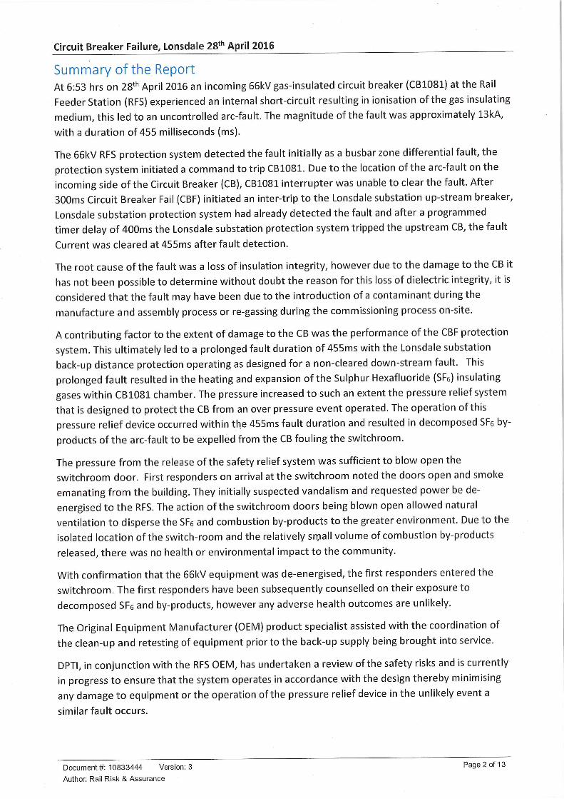
The Rail Feeder Station (RFS) is located off Meyers Rd Lonsdale adjacent the Adelaide to Seaford Rail Line.
The Lonsdale substation is located to the west of the RFS as detailed in Figure 1 DPTI Rail Feeder Station
location.
Figure 1 DPTI Rail Feeder Station location
Rail Feeder Station Configuration
There are two incoming supplies from Lonsdale substation configured as primary and back-up to the RFS, of
which only one can be supplying power at any one-time. The configuration provides duplication of the supply
from Lonsdale substation but the two supplies must never be tied together through the GIS switchgear. The
RFS monitors, manages power quality and distributes the supply to duplicated 66/25kV transformers that
provide supply to the Seaford Rail overhead line traction system.
The 66kV Gas Insulated Switchgear (GIS) system can be configured to manage power availability, power
quality or various degraded or emergency feeding arrangements in response to maintenance requirements
or equipment fault and is monitored and controlled by a Supervisory Control and Data Acquisition (SCADA)
system located remotely in the rail Operational Control Centre.
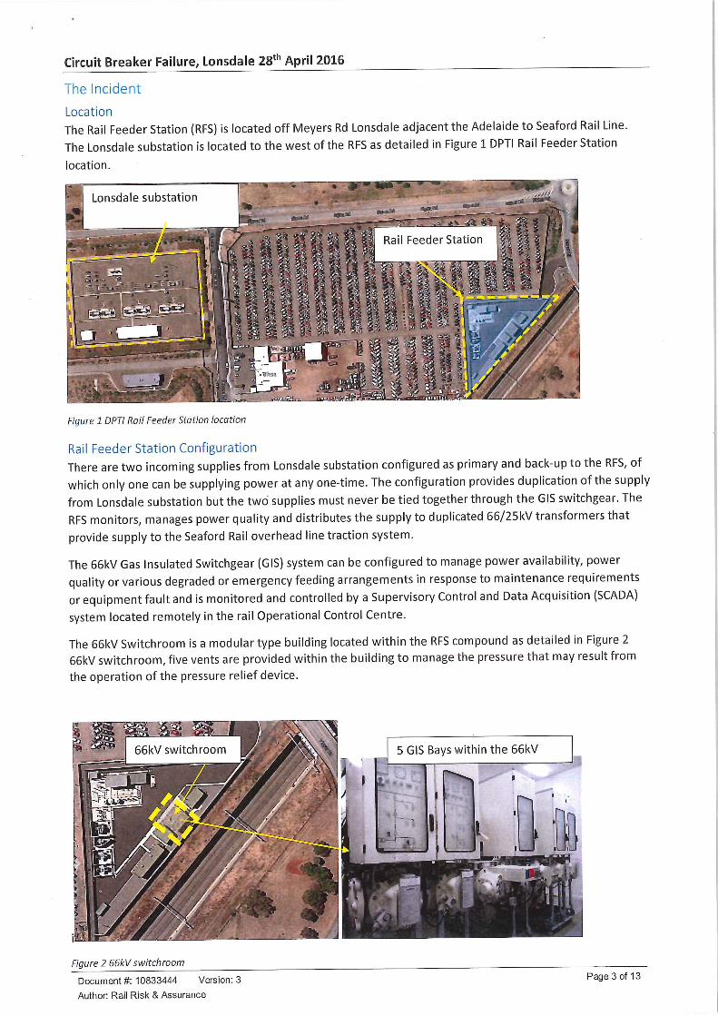
The 66kV Switchroom is a modular type building located within the RFS compound as detailed in Figure 266kV switchroom, five vents are provided within the building to manage the pressure that may result from
the operation of the pressure relief device.
5 GIS Bays within the 66kV
Figure 2 66kV switch room
Document #: 10833444 Version: 3
Author: Rail Risk & Assurance
Page 3 of 13
Circuit Breaker Failure, Lonsdale 28th April 2016
Equipment involved
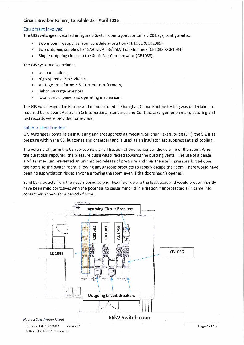
The GIS switchgear detailed in Figure 3 Switchroom layout contains 5 CB bays, configured as:
• two incoming supplies from Lonsdale substation (CB1081 & CB1085),
• two outgoing supplies to 15/20MVA, 66/25RV Transformers (CB1082 &CB1084)
• Single outgoing circuit to the Static Var Compensator (CB1083).
The GIS system also includes:
• busbar sections,
• high-speed earth switches,
• Voltage transformers & Current transformers,
• lightning surge arrestors,
• local control panel and operating mechanism.
The GIS was designed in Europe and manufactured in Shanghai, China. Routine testing was undertaken as
required by relevant Australian & International Standards and Contract arrangements; manufacturing and
test records were provided for review.
Sulphur Hexafluoride
GIS switchgear contains an insulating and arc suppressing medium Sulphur Hexafluoride (SFe), the SFs is at
pressure within the CB, bus zones and chambers and is used as an insulator, arc suppressant and cooling.
The volume of gas in the CB represents a small fraction of one percent of the volume of the room. When
the burst disk ruptured, the pressure pulse was directed towards the building vents. The use of a dense,
air-filter medium prevented an uninhibited release of pressure and thus the rise in pressure forced open
the doors to the switch room, allowing any gaseous products to rapidly escape the room. There would have
been no asphyxiation risk to anyone entering the room even if the doors hadn't opened.
Solid by-products from the decomposed sulphur hexafluoride are the least toxic and would predominantly
have been mild corrosives with the potential to cause minor skin irritation if unprotected skin came into
contact with them for a period of time.
Incoming Circuit Breakers
r^"^.iu^ra[ s HJ ni i'SJl;-^ Ji?.—JiJ—^T";' ^33"y-_3r «-.fcEu£.±~^j^^t^—@? L^jy- L-_J_^
Outgoing Circuit Breakers
Figure 3 Switchroom layout 66kV Switch room
Document#: 10833444 Version: 3
Author: Rail Risk & Assurance
Page 4 of 13
Circuit Breaker Failure, Lonsdale 28th April 2016
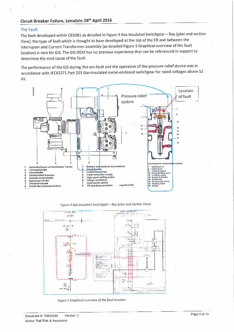
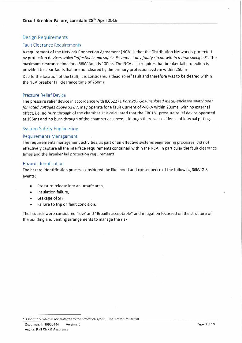
The FaultThe fault developed within CB1081 as detailed in Figure 4 Gas Insulated Switchgear-Bay (plan and section
View), the type of fault which is thought to have developed at the top of the CB and between the
interrupter and Current Transformer assembly (as detailed Figure 5 Graphical overview of the fault
location) is rare for GIS. The GIS OEM has no previous experience that can be referenced in support to
determine the root cause of the fault.
The performance of the GIS during this arc-fault and the operation of the pressure relief device was in
accordance with IEC62271 Part 203 Gas-insulated metal-enclosed switchgearfor rated voltages above 52
kV.
Pressure relief
system A
Sammelschienen und kombinierte TrennerLeistungsschalterStromwandlerKabelanschfuB-BausteinSchnellerdungsschalterSpannungswandlerOrtssteuerschrankAntrieb des Leistungsschalters
1 Busbars and combined disconnectors2 Circuit-brf3 Current transformer4 Cable connection module5 High-speed earthing switch6 Voltage transformer7 Local control cabinet8 CB operating mechanism Page 60 of 345
Switching system, shown njinc^jt conductor
Operabng i6\.erInsulat rg redIpsulatrg support1/avmg conlact sjoso-tSlabbing /o'ume
12 ExpannanchanberExhaust tube
14 Ucww arcing contact15 Insubl rg nozzts1B tnsuialsr
Location
of fault
10
13
Figure 4 Gas Insulated Switchgear- Bay (plan and section View)
;L?-D 101
.FA01
!--— —-..+—
$.^'1 •:?,;;;C^':'l
--:;•
'.?>
•^---^r-^'
j;(
['!••
')-
N^
,̂c|>-,ct>-
-"ct
,<{>-
^
.%
Pa'jiTpos'hc.n
~Y-'--
":Tt"
frl~~
w;H:1-
1
!I .
*-i
Figure 5 Graphical overview of the fault location
Document #: 10833444 Version: 3
Author: Rail Risk & Assurance
Page 5 of 13
Circuit Breaker Failure, Lonsdale 28tn April 2016
Design Requirements
Fault Clearance Requirements
A requirement of the Network Connection Agreement (NCA) is that the Distribution Network is protected
by protection devices which "effectively and safely disconnect any faulty circuit within a time specified". The
maximum clearance time for a 66kV fault is 100ms. The NCA also requires that breaker fail protection is
provided to clear faults that are not cleared by the primary protection system within 250ms.
Due to the location of the fault, it is considered a dead zone1 fault and therefore was to be cleared within
the NCA breaker fail clearance time of 250ms.
Pressure Relief Device
The pressure relief device in accordance with IEC62271 Part203 Gas-insulated metal-enclosedswitchgear
for rated voltages above 52 kV; may operate for a fault Current of <40kA within 200ms, with no external
effect, i.e. no burn through of the chamber. It is calculated that the CB0181 pressure relief device operated
at 196ms and no burn through of the chamber occurred, although there was evidence of internal pitting.
System Safety Engineering
Requirements Management
The requirements management activities, as part of an effective systems engineering processes, did not
effectively capture all the interface requirements contained within the NCA. In particular the fault clearance
times and the breaker fail protection requirements.
Hazard identification
The hazard identification process considered the likelihood and consequence of the following 66kV GIS
events;
• Pressure release into an unsafe area,
• Insulation failure,
• Leakage of SFs,
• Failure to trip on fault condition.
The hazards were considered "low' and "Broadly acceptable" and mitigation focussed on the structure of
the building and venting arrangements to manage the risk.
A short zone which is not protected by the protection system, (see Glossary for detail)
Document #: 10833444 Version: 3 Page 6 of 13
Author: Rail Risk & Assurance
Circuit Breaker Failure, Lonsdale 28tn April 2016
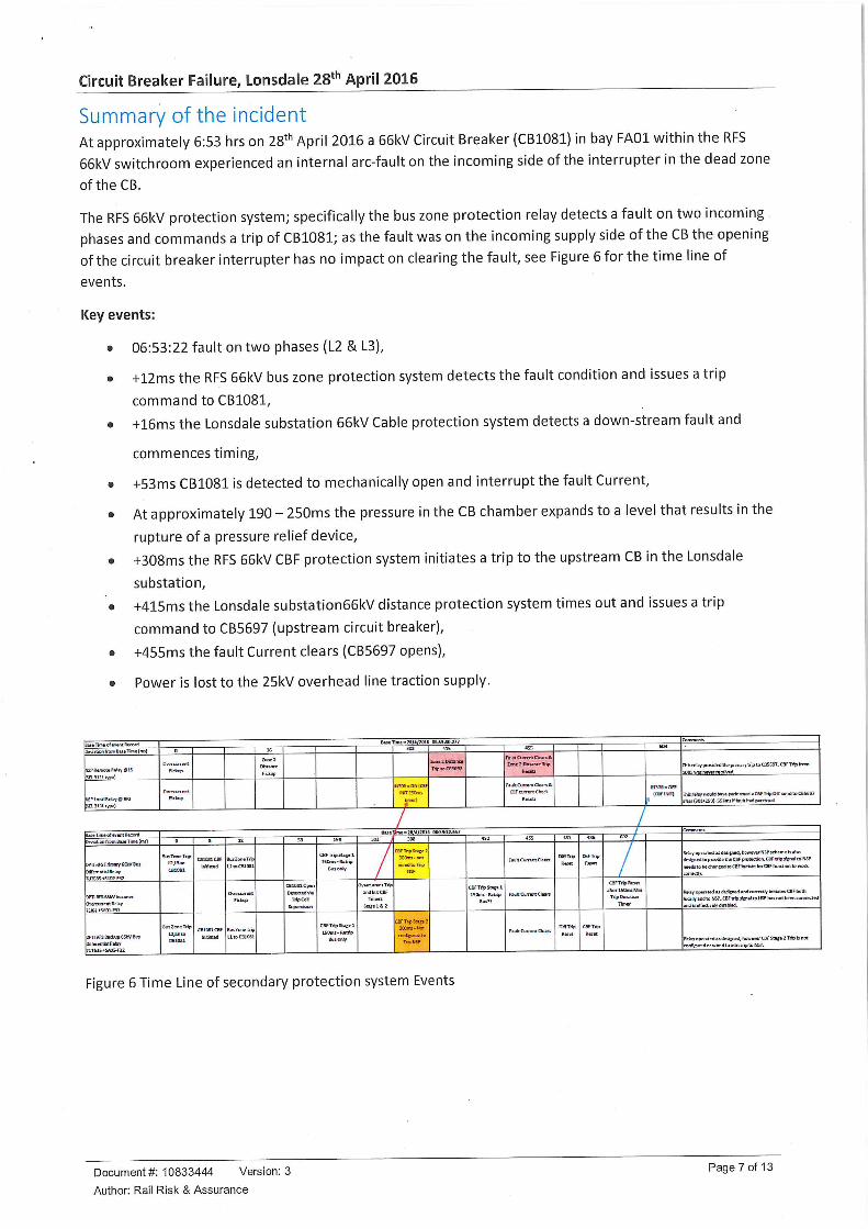
Summary of the incidentAt approximately 6:53 hrs on 28th April 2016 a 66kV Circuit Breaker (CB1081) in bay FA01 within the RFS
66kV switchroom experienced an internal arc-fault on the incoming side of the interrupter in the dead zone
of the CB.
The RFS 661<V protection system; specifically the bus zone protection relay detects a fault on two incoming
phases and commands a trip ofCBlOSl; as the fault was on the incoming supply side of the CB the opening
of the circuit breaker interrupter has no impact on clearing the fault, see Figure 6 for the time line of
events.
Key events:
• 06:53:22 fault on two phases (L2 & L3),
• +12ms the RFS 66kV bus zone protection system detects the fault condition and issues a trip
command to CB1081,
• +16ms the Lonsdale substation 66kV Cable protection system detects a down-stream fault and
commences timing,
• +53ms CB1081 is detected to mechanically open and interrupt the fault Current,
• At approximately 190 - 250ms the pressure in the CB chamber expands to a level that results in the
rupture of a pressure relief device,
• +308ms the RFS 66kV CBF protection system initiates a trip to the upstream CB in the Lonsdale
substation,
• +415ms the Lonsdale substation66kV distance protection system times out and issues a trip
command to CB5697 (upstream circuit breaker),
• +455ms the fault Current clears (CB5697 opens),
• Power is lost to the 25kV overhead line traction supply.
iue Tune of tvwit Rtcord:)tvhticn from Bue Tme (mi)
ISPRunot? Rel^etS
sa.su'.tns)
:iB.3ULw«]
SwntionfomBaieTmt^nu)
yn RFS frimay S EkV Bui
>ffMntiriRd*-/
fSJK+SAOl-Rl
>mitfSBai±up6SWBuJ
'UTG35+yu3-F32
a
Ownunint
Fid.-up
Pid-up
16
DiltUKE
Fidup
Bau
Base
0
SuiZaieTT,|12^3 n>
CSIOE1
CSUlfil
s
CSUBtCM
tosaad
CSIBS1CBF
hrdEtd
12
lui Zone TIT
Ch'ercurentPIAup
•wZawJt-v
LI10C3IOS1
53
csicaiopui
Trip Coi
SupBrvcaon
153
CBFTripStas'l
ISOnu.Retiy
iiu only
CSFTripStassl
ISOmi-ReUip
Eusonl/
302
2Sa;n&2
7^/t308
H3(a=OU|t£T[IWT25am
r"
415
EDneZDuiana
Tripuceses?
flSS
FaiaCurettCtean;&
ZmiaDBiiaiffiTnp
&cm
Fiu;tCumnta*an&
z:[™»Z«/</2m6 DE:S3:22A57
308
SFTrpSraet:SOCha-nnt
nutduTripiep
WT^,aws\BCQmt.Ha
CIHrttBTiCTO
TflpHSP
3FTripSCt(il
15 ?iu.HempBin??
FnACurrmtCl™
FaBHCufTEntdEira
WljHf,
tta*t
DiffTrip
ilEiet
Wf.
CBF Trip
ResK
Rest
1CBF1WT)
•srrmtnts
Tie relay pnnided the pri-naty trip to Cfl5657. CSFTrpfram
HiiFnlT/vri>uld(iaveF*rfnnj)?d3CSS-Tfv&t7imdtOCB5S57[ETt3!)2tZSOb5SBiTuiffauhh3!lptm™l
/
_i-J_
//
CSFTrvteitl
aterlSOnBMii
TripDuisaon
TMner
;e^r operated ani£li£ned,fiDweiwNSP scheme is atio
[uipiedtopnmdiiTheCBfpfDteCtion.CBfWlpliFUltoriSF
leedi to be chaneed to CSF inftintE fm- CSf ftmaion te wcrk
.y optnl&d u duis""'»":1 ccr""t/"•^"'s CBF both
Ka!>r »nd1o HS?. CBF trip signll to ItSP hu not been cwaiEtd
nd u eftcmeh rimbted.
ry opsnted u duipiK^, hawncr CS; Sta^e 2 Try il oct
onflsund crwnd to i(tt£rav ta N5P.
Figure 6 Time Line of secondary protection system Events
Document #: 10833444 Version: 3
Author: Rail Risk & Assurance
Page 7 of 13
Circuit Breaker Failure, Lonsdale 28th April 2016
The ResponseThe power outage was observed by the Electrical Control Officer (ECO), on the SCADA system located
remotely in the Rail Operations Control Centre. The ECO in discussions with the Electrical Engineer
immediately commenced reconfiguring the system to an alternative feeding arrangement and after
discussion with Lonsdale substation controller, commenced re-energising the back-up Lonsdale substation
66kV feeder, reconfiguring the 66kV switchgear and reinstated supply to the 25kV overhead line traction
supply.
• 06:53 CB1081 displays "Open" status and multiple alarms displayed on the SCADA. The ECO
identifies loss of power and advises Seaford Line Controller (Operations Controller) and rail Shift
Manager of loss of supply,
• 06:58 ECO tiaises with Lonsdale substation Controller to identify issue and restores power to
standby circuit (Feeder 2),
• 07:08 power restored to the 25kV overhead line traction supply,
• Electrical Engineering interrogate the SCADA system to understand fault and decide to despatch an
Electrical Engineer to site to investigate,
• 07:42 Electrical Engineering, confirm attendance at Lonsdale. Electrical Engineering observes the
doors open and smoke emanating from the 66kV switchroom. Electrical Engineering contact the
Electrical Engineer Manager and a decision is made to immediately shutdown the supply to the RFS,
• 07:49 CB1085 is opened, stranding electric trains on the network,,
• 08:16 Lonsdale substation are contacted to isolate power from Feeder 2, so Electrical Engineers can
enter switch room,
• 08:30 Electrical Engineering enter switchroom and observe burn-marks on the CB1081 and damage
to adjacent 66kV GIS CB Bay,
• 09:30 The OEM supplier is contacted and advised of the incident,
• 10:45 The OEM supplier is contacted and requested to attend site,
• 15:00 On arrival on-site Lonsdale RFS OEM, product specialist advised the potential hazards of
coming into contact with the decomposed SFs by-products,
• 16:40 OEM product specialist advises the needs to thoroughly clean the switchroom to remove the
traces of the decomposed SFe by-products.
Document #: 10833444 Version: 3 Page 8 of 13
Author: Rail Risk & Assurance
Circuit Breaker Failure, Lonsdale 28th April 2016
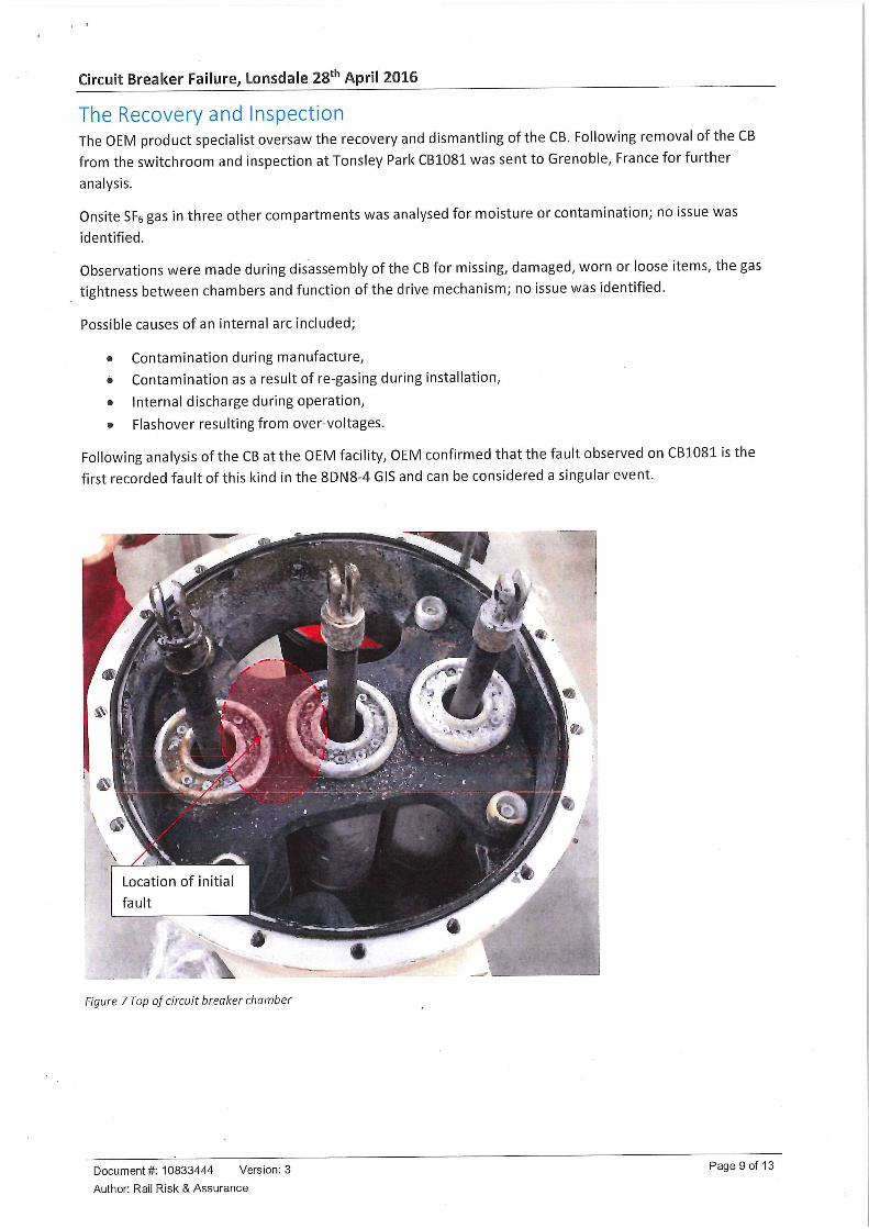
The Recovery and InspectionThe OEM product specialist oversaw the recovery and dismantling of the CB. Following removal of the CB
from the switchroom and inspection at Tonsley Park CB1081 was sent to Grenoble, France for further
analysis.
Onsite SFg gas in three other compartments was analysed for moisture or contamination; no issue was
identified.
Observations were made during disassembly of the CB for missing, damaged, worn or loose items, the gas
tightness between chambers and function of the drive mechanism; no issue was identified.
Possible causes of an internal arc included;
• Contamination during manufacture,
• Contamination as a result of re-gasing during installation,
• Internal discharge during operation,
• Flashover resulting from over-voltages.
Following analysis of the CB at the OEM facility, OEM confirmed that the fault observed on CB1081is the
first recorded fault of this kind in the 8DN8-4 GIS and can be considered a singular event.
Figure 7 Top of circuit breaker chamber
Document #: 10833444 Version: 3
Author: Rail Risk & Assurance
Page 9 of 13
Circuit Breaker Failure, Lonsdale 28tn April 2016
Key facts and analysisThe Control and Protection Study produced at time of design by the Contractor, considered the concept of
separability and system grading.
Event recordings of the supply show that a Current of 12.9KA flowed for 455 milliseconds.
There was no indication of any defect in the CB1081 prior to the incident.
Summary of Conclusions
Root cause
The root cause of the incident was the sudden loss of the insulation integrity leading to an internal arc in
the dead zone of CB1081.
Whilst it is not possible to determine without doubt, the cause fault is an insulation failure within the circuit
breaker.
Escalation factors
Escalation factors include:
• The extended duration of the fault, resulting in excess pressure within the CB chamber resulting in
the operation of the pressure relief device.
The following factors were also related:
• The CBF signalling scheme from DPTI RFS to Lonsdale substation was not established by DPTIand
its contractors in the most effective manner.
• The Systems Engineering process did not identify the criticality of the requirement for clearing a
fault within 250ms as detailed in the NCA nor its relationship to the operation of the pressure relief
device.
Actions reported as already taken or in progress relevant to this report.
As an interim measure DPTI with Lonsdale substation modified the upstream protection to
"instantaneously trip for fault", rather than the 400ms Distance Trip delay that was in place on the 28th
April 2016. Whilst in the interim this may have resulted in a greater chance of nuisance tripping it affords
greater protection to the GIS CB should an internal fault occurred.
DPTI has undertaken a review of the design of the RFS protection system, the interface with Lonsdale
substation back-up protection system and the redundancy of the system. This review identified a number
of improvements to the protection system design to reduce the probability of an arc-fault being sustained
for sufficient time and magnitude to reduce the likelihood of the operation of the pressure relief device to,
so far as reasonable practicable (SFAIRP), these changes were implemented progressively and completed in
November 2016.
A modified design and protection settings was implemented on the secondary protection system for Feeder
No. 1 (CB1081), with a full functional test being carried out including the interface with Lonsdale substation
to confirm compliance to the NCA requirements, in particular the fault clearance times. This test was
successfully completed on Feeder No. 1 on the 16th October prior to CB10181 being put back into service;
modifications to Feeder no. 2 secondary protection system were completed on the 20th November 2016.
Restrictions on access to the 66kV switchroom whilst the 661<V equipment was energised, has been lifted;
the RFS OEM has reviewed the safety arrangements within the 66kV switchroom and completed the
following inspections or modifications to address safety concerns:
Document #: 10833444 Version: 3 Page 10 of 13
Author: Rail Risk & Assurance
Circuit Breaker Failure, Lonsdale 28tn April 2016
• Inspection of the in-service 8DN8-4 circuit breakers to identify any contamination or internal
damage to the CB upper chamber
a Review the venting arrangement within the room to ensure in the case of a rupture of the pressure
relief device that the vents operate
• Confirmation of the direction of the blast deflectors
• Modification to the protection system so that the fault duration will be limited to less than
approximately 150ms
• Update the Contractor RFS Safety Assurance Report.
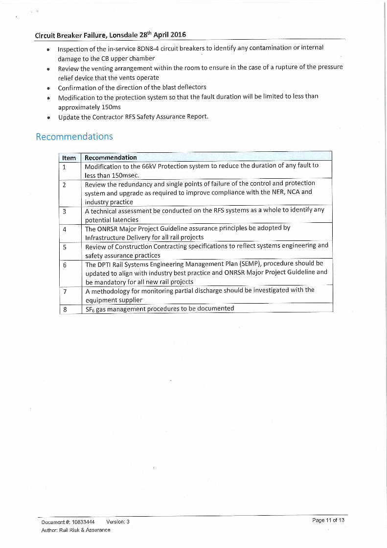
Recommendations
Item
1
2
3
4
5
6
7
8
Recommendation
Modification to the 66RV Protection system to reduce the duration of any fault to
less than 150msec.
Review the redundancy and single points of failure of the control and protection
system and upgrade as required to improve compliance with the NER, NCA and
industry practice
A technical assessment be conducted on the RFS systems as a whole to identify any
potential latencies
The ONRSR Major Project Guideline assurance principles be adopted byInfrastructure Delivery for all rail projects
Review of Construction Contracting specifications to reflect systems engineering and
safety assurance practices
The DPTI Rail Systems Engineering Management Plan (SEMP), procedure should beupdated to align with industry best practice and ONRSR Major Project Guideline andbe mandatory for all new rail projects
A methodology for monitoring partial discharge should be investigated with the
equipment supplier
SFs gas management procedures to be documented
Document #: 10833444 Version: 3
Author: Rail Risk & Assurance
Page 11 of 13
Circuit Breaker Failure, Lonsdale 28tn April 2016
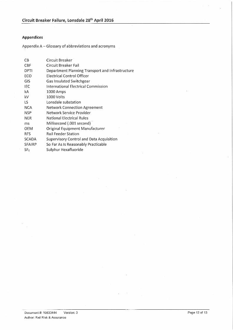
Appendices
Appendix A - Glossary of abbreviations and acronyms
CB Circuit Breaker
CBF Circuit Breaker FailDPTI Department Planning Transport and Infrastructure
ECO Electrical Control OfficerGIS Gas Insulated Switchgear
IEC International Electrical Commission
kA 1000 Am pskV 1000 Vo ItsLS Lonsdale substation
NCA Network Connection Agreement
NSP Network Service Provider
NER National Electrical Rulesms Millisecond (.001 second)OEM Original Equipment Manufacturer
RFS Rail Feeder StationSCADA Supervisory Control and Data Acquisition
SFAIRP So Far As Is Reasonably PracticableSFe Sulphur Hexafluoride
Document #: 10833444 Version: 3 Page 12 of 13
Author: Rail Risk & Assurance
Circuit Breaker Failure, Lonsdale 28th April 2016
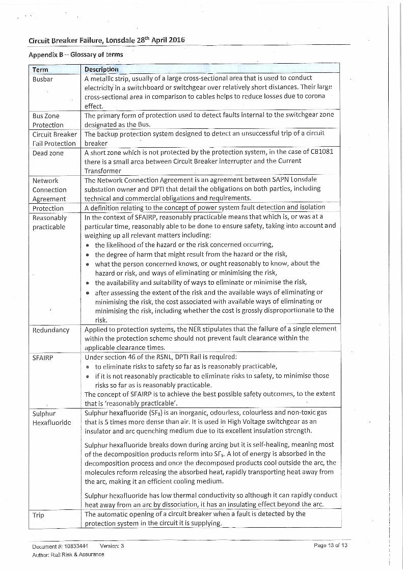
Appendix B ~ Glossary of terms
Term
Busbar
Bus Zone
Protection
Circuit Breaker
Fail Protection
Dead zone
Network
Connection
Agreement
Protection
Reasonably
practicable
Redundancy
SFAIRP
SulphurHexafluoride
Trip
Description
A metallic strip, usually of a large cross-sectional area that is used to conduct
electricity in a switchboard or switchgear over relatively short distances. Their large
cross-sectional area in comparison to cables helps to reduce losses due to corona
effect.
The primary form of protection used to detect faults internal to the switchgear zone
designated as the Bus.
The backup protection system designed to detect an unsuccessful trip of a circuit
breaker
A short zone which is not protected by the protection system, in the case of CB1081
there is a small area between Circuit Breaker interrupter and the Current
Transform er
The Network Connection Agreement is an agreement between SAPN Lonsdale
substation owner and DPTI that detail the obligations on both parties, including
technical and commercial obligations and requirements.
A definition relating to the concept of power system .fault detection and isolation
In the context of SFAIRP, reasonably practicable means that which is, or was at a
particular time, reasonably able to be done to ensure safety, taking into account and
weighing up all relevant matters including:
• the likelihood of the hazard or the risk concerned occurring,
• the degree of harm that might result from the hazard or the risk,
• what the person concerned knows, or ought reasonably to know, about the
hazard or risk, and ways of eliminating or minimising the risk,
• the availability and suitability of ways to eliminate or minimise the risk,
• after assessing the extent of the risk and the available ways of eliminating or
minimising the risk, the cost associated with available ways of eliminating or
minimising the risk, including whether the cost is grossly disproportionate to the
risk.
Applied to protection systems, the NER stipulates that the failure of a single element
within the protection scheme should not prevent fault clearance within the
applicable clearance times.
Under section 46 of the RSNL, DPTI Rail is required:
s to eliminate risks to safety so far as is reasonably practicable,
• if it is not reasonably practicable to eliminate risks to safety, to minimise those
risks so far as is reasonably practicable.
The concept of SFAIRP is to achieve the best possible safety outcomes, to the extent
that is 'reasonably practicable'.
Sulphur hexafluoride (SFs) is an inorganic, odouriess, colourless and non-toxic gas
that is 5 times more dense than air. It is used in High Voltage switchgear as an
insulator and arc quenching medium due to its excellent insulation strength.
Sulphur hexafluoride breaks down during arcing but it is self-healing, meaning most
of the decomposition products reform into SFc. A lot of energy is absorbed in the
decomposition process and once the decomposed products cool outside the arc, the
molecules reform releasing the absorbed heat, rapidly transporting heat away from
the arc, making it an efficient cooling medium.
Sulphur hexafluoride has low thermal conductivity so although it can rapidly conduct
heat away from an arc by dissociation, it has an insulating effect beyond the arc.
The automatic opening of a circuit breaker when a fault is detected by the
protection system in the circuit it is supplying.
Document #: 10833444 Version: 3
Author: Rail Risk & Assurance
Page 13 of 13