Embed Size (px)
Citation preview

RAILWAY BRIDGES AND TUNNELS
BY: - CIVIL ENGINEERING DEPARTMENT
B.K.N. GOVT. POLYTECHNIC NARNAUL

CONTENT COVERED
1. Introduction
2. Railway Survey
3. Rail Gauge
4. Rails
5. Rail Fastenings
6. Sleepers
PART-B BRIDGE
1. Bridge Engineering
2. Site selection and collection of data
3. Foundation
PART- C TUNNEL
1. Tunnel
2. Tunneling and lining

1. INTRODUCTION
There are different modes of transport for frequent movement from one place to other.
Even mode has their own significance, but among all Railway has great utility and
influence on our day to day life.
The concept of railway is very interesting in old days when horse driven vehicles
moved over wooden planks these are termed as tram ways, however when
wooden planks are replaced by iron plates, these were termed as plate way and
presently iron plates are being replaced by iron angles known as rails. One thing is
common among the old days horse driven vehicles that is horse worked as Engine
and Cart worked as bogie (Rail Compartment). With the advancement of technology
shape of railway changed; George Stephenson was first man to invent the steam
locomotive. which is being used till date to drive rail compartments.
‘With the passage of time, development in technology replaces these steam
engines with Diesel Engines as well as Electrically operated Engines.
Ra i lways impa r t grea t economy in the deve lop ment o f count ry Deve lop in g
countries like India, railway plays integral role in the develop ment as well as
national integrity of the nation.
DEVELOPMENT OF RAILWAYS IN INDIA
Railway development was not an easy task but great efforts were made to make it
compatible and finally it is proved that the efforts made for the developments of
Railways lead great success, it was continuous and regular efforts. If we go through the
history of railway it is evident that attention were made in 17th century and finally
George Stephenson resulted in the running the first train of the world on 27th Se ptember
1825 between Stockton and Darlington.
Britishers were the first to introduce the system of railways in India. In India the first
railway line was laid in 1853 and run first train on 16th April 1853 between Bombay t o
T h a n e .
1 8 5 4 – S e c o n d r a i l w a y l i n e f r o m H o w a r h t o P a n d o o a w a s o p e n e d
1 8 5 5 - 1 8 6 2 – N o r t h I n d i a w a s c o n s t r u c t e d w i t h h e l p o f 8 c o m p a n i e s
1 8 7 9 – I n d i a h a s a t o t a l o f 1 4 9 2 0 k ms r a i l w a y l i n e .
1 8 8 0 – T h e r e c o m m e n d a t i o n o f 8 0 0 0 k m o f n e w r a i l w a y l i n e
1 8 8 1 - L o r d H a r t i n g t o n f o r m u l a t e d t h e r u l e s f o r r a i l w a y c o n s t r u c t i o n
1 8 8 1 - 1 8 9 7 - N e w c o n t r a c t s w e r e g i v e n t o t h e 7 N e w C o m p a n i e s t o r
d e v e l o p me n t o f R a i l w a y .
1 9 0 1 - S p e c i a l A t t e n t i o n w a s g i v e n b y a p p o i n t i n g M r . T h o m a s
R o b e r t s o n t o i n v e s t i g a t e i n t o R a i l w a y a d m i n i s t r a t i o n , o r g a n i z a t i o n a n d
S y s t e m.
1 9 0 5 - R a i l w a y B o a r d w a s e s t a b l i s h e d u n d e r t h e d e p a r t m e n t o f
C o m me r c e a n d I n d u s t r i e s
1 9 0 7 - Mckay Committee was appointed to examine the railway problems
1908 - Railway Board was re-organised to improve the railway
1 9 1 4 - 1 9 2 1 - R a i l w a y k i l o m e t r a g e w a s i n c r e a s e d u p t o 5 8 , 7 7 6 k m s
1 9 2 2 - 1 9 3 9 - K i l o me t e r a g e w a s i n c r e a s e d u p t o 6 5 , 8 5 0 k m s .
1 9 4 7 - 4 8 - D u e t o P a r t i t i o n o f I n d i a , I n d i a n R a i l w a y s s u f f e r e d g r e a t .
l o s s .
1 9 4 8 - 5 0 - G o v e r n m e n t a c q u i r e d c o n t r o l o v e r a l l r a i l w a y s e x c e p t f e w
p r o c o m p a n i e s .
The entire Railway system comprising of 35 Railway Administrations before April, 1951
was re-grouped into the following nine zones :
Eastern Railway (E.R.).
South-Eastern Railway (S.E.R.)
Northern Railway (N.R.).
MI North Eastern Railway (N.E.R.)
Southern Rai lway (S.R. ) .
Central Railway (C.R.).
Western Railway (W.R.).
North East Frontier Railway (N.F.R).
South Central Railway (S.C.R.). .
After this, there was a rapid development of Railways in India which was achieved
through the following five year plans :-
First Five Year Plan (1951-56) : In this plan, the total investment on Railways was Rs.
423 crores. This plan considerably helped India in achieving self sufficiency.
Chitrarjan Locomotive Works and Tata Engineering and Locomotive boosted up their
production during this plan.
Second Five Year Plan (1956-61) : In this second five year plan, a total provision was
increased up to 1.044 crores, for ,the development of Railways in India. This plan made
the country self sufficient in railway equipment and transportation.
Third Five Year Plan (1961-66) : In this plan, a sum of Rs. 1,686 crores was increased for
the development of Indian Railways. During this plan, many locomotives wagons and
coaches were acquired. It also provided for doubling of track, complete track
renewals, etc., Besides this, many bridges, staff quarters, railway stations and other
facilities were undertaken. This plan helped the railways in building infra structures.
Fourth Five Year Plan (1969-74) : In fourth five year plan, a sum of Rs. 1.557 crores
was retained for the development of Indian Railways. During this plan, more attention
was given on addition and replacement of rolling stock.
Fifth Five Year Plan (1974-79) : In this plan, a sum of Rs. 2,350 crores was kept for
the development of Indian Railways In order to have the uni -gauge over the large area,
conversion of Metre gauge to Broad gauge (B G.) was Ta ken in hand during this Five
Year Plan. As in the case of earlier plans. the main objective of this plan was to pr ovide
capacity for freight and passenger traffic was anticipated during the Precious Plans,
keeping in view for the developments of the country and national economy.
SYSTEMS OF RAILWAYS
The Railways can be provided on, above and below the ground surface, suiting to the
topography of the area. Further, the Railways below ground surface can be constructed just
below the ground level or at greater depths.
There are the following four systems of Railways :-
1. Surface railways ;
2. Elevated railways ;
3. Under ground railways ;
4. Tube railways.
1. Surface Railways
The railways provided over the ground surface are known as surface railways.
Suitability : This system of Railways is most extensively used throughout the world because this is the
best system for transporting people andgoods. In surface railways , the various means like
*level crossings over-bridge or under-bridge are to be provided for crossing of the railway and
road traffic safely and efficiently.
2. Elevated Railways
The railways provided at higher or elevated portion, above the ground surface are called "high
level" or "elevated railways".
In this system of Railways, a continuous viaduct supported on piers, columns, etc. i5 constructed and
the track is carried on its steel deck. This system is very costly because buildings like stations,
waiting halls, offices are to be constructed at high levels requiring stair cases, escalators, etc. But
elevated railways cause little obstruction due to piers, columns supporting the, track,
3 . Under Ground Railways
The railways provided just below ground level are called "low level or underground railways.
In this system of Railways, tunnels are constructed for carrying tracks through them and a
over-bridge is necessary at every road-crossing to carry the road traffic over the railway
traffic. Due to ventilation problem in tunnels, electricity is the only so urce of power for
traction in under ground railways.
Advantages :-
(i) This system provides rapid and unobstructed transportation.
(ii) This system helps in reducing traffic congestion problems.
(iii) This system provides safety during aerial attack in war.
Suitability : Under ground railways are suitable in the heavily congested urban areas
where the traffic intensity on roads is heavy.
Tube Railways
The railway provided underground at a greater depth of about 18 m or more (upto 52m) are
called tube railways.
This system of Railways is so called as the section of the underground tunnels, carrying
the track, is circular like a tube. The main purpose of providing tube railways is to avoid the
interference of the tracks with water and gas pipes, sewerage systems and oil or drainage
pipes, etc.
Some important feautures of the tube railways are given below :
(i) The railways stations have to be of cylinderical form.
(ii) Escalators or moving s tair Cases are to be constructed to reach the tube
railways.
(iii) Only electric traction is to be uses to avoid the smoke and ventilation problems.
(iv) Automatic signalling system is to be used.
(v) Such a mechanism of the train is to he used that it cannot start until all the doors
are closed, and it automatically stops, if the signal is at 'STOP' position.
ADVANTAGES OF RAILWAYS
Railway imparts great significance on over day to day life. These may be classified as :
1. Political significance
2. Social significance
3. Economic significance
Political Significance
(i) Railway unites the people of different caste, religion, customs thus helps
integrity of the nation.
(ii) With the help of railway networking central administrative control become
easy and effective.
(iii) The role of railways for mobilizing troops and war equipment cannot be denied
during emergencies.
(iv) Railway Network easy migration of people thus impart political stability to the
nation.
Social Significance
1. Railway has made movement of people easy thus social integrity results due to railway
networking.
2. Railway does not made restriction on the movement of caste, race etc thus feeling of
humanity increased by travelling in rail compartments.
3. Railway has made the Journey's of religious places easier thus strengthens the social
advantages among the people.
4. Railways journey's increases social outlook of masses as it provide easy way to meet the
people's of different part of the Country.
Economic Advantages
1. The mobility of masses contributed to industrial development.
2. Transportation facility for raw as well as finished goods from the fac to r ies
helped rapid growth of industrial development.
3. Railway has great employment thus solving the problem of unemployment up to
great extent.
4. Easy movement of goods helps the nation against inflation problem of the country.
FEATURES OF INDIAN RAILWAY
Railway is one of the most important mode of transportation. In the modern era rail transport
is the index feature of nation's economic, social, political as well as industrial
development. In Developing country like India rail transport is the backbone of the
country Railway transport is an economical means of transportation in India for
commercial as well as passanger's per's movement Some of the main features arc
discussed below
1. Indian Railways are the biggest undertaking in the world
2. Indian railway contributes major employment opportunity among the world.
3. Indian railways are the cheapest mode of transportation among the other modes of
transportation.
4. Railway has its unique way of movement thus keeps easy movement without
traffic congestions.
5. Development of electric railway keeps in protecting environment against
pollution.
6. Railway need less traction to move it in comparison to its weight.
7. The rate of accidents are minimum in case of railways.
2. RAILWAY SURVEY
INTRODUCTION
To get the optimum position of railway rout, before laying is called railway survey on the
ground and giving direction to the railway track is only possible through the operation
of railway survey. The location of this railway track is also called alignment of track.
Broadly a lignment of ra ilway t rack comprises of win two components
1. Horizontal components
2. Vertical components
1. Horizontal Components : It includes straight path, its width, curves an deviations
in width.
2. Vertical Components: It includes changes in vertical curves and gradients. Both these
components plays vital role while ascertaining optimum railway track or setting out
alignment of railway track. While determining the alignment of railway track every
care should be taken, and numbers of factor relating to setting out alignment should
carefully be studied which & directly or indirectly affects the rail route. A little mistake in
alignment of track can prove un-economical in construction as well as maintenance of track
and operation in movement of vehicles. It is obvious that once the track is constructed it
is impossible to alter the track because it involves large initial cost of construction and it is
nearly impossible to change the track so while setting out alignment various factors should
be considered in mind and proper survey should he carried out to get most economical
track alignment.
FACTORS INFUUENCING THE RAILWAY ROUTE
While determining railway route or alignment it is kept in mind that it should be straight
between the two terminal stations, but this condition is not always be possible because of
available topographical conditions of the area to be surveyed, such as intermediate
obstruction, steep quotients, construction problems etc. along route.
It is observed that the route which is most economical in initial cost does not prove
economical in operations. It means that same times operation list on such alignment
prove costlier than other available alternative routes. Thus it is concludes that all
requirements does not met simultaneously so following are some factors which
should be kept in mind while aligning the track : -
1. Religious Places : The track which is to be determined should never cross
trough religious buildings or structure. If these types of obligations comes in the way the
track or alignment must be deviated.
2. Areas of flood/snow fall : The rail alignment also effected if such area like
flood prone or heavy snowfall comes across the alignment which cause considerable
problem in operations of railways. Thus alternative possible routes are find out for the
alignment.

3. Obligatory Points : Railways alignments should be determined keeping in
view of some obligatory points which have some importance like defence importance,
intermediate towns, towns of commercial importance etc.
4. Future Traffic Growth - The route should be such that it will incorporate future
growth of traffic so that initial cost for future can be minimized for future.
5. Geometric Design : It is the vary important factor which affect the route of
railway while determining the alignment it should be carefully studied. geometric
design of railway alignment covers gradients, curves factors. For gradient it should be
below 3% i.e. it should be normal or ruling gradient where as in case of curves should he
maximum possible radii.
6. Topography of Area - Topography means the geographical conditions of the
area where the railway should be aligned. This is most serious factor of railway track
alignment and seriously affect the railway route considerably. So while considering
optimum railway track it should be seriously studied according to topography There
may be three types of alignments
1. Valley alignment
2. Cross country alignments
3. Mountain alignment
Depending upon the conditions available in the region any suitable alignment is
adopted to set up the track. Further to achieve the development, to limit the gradient upto
ruling gradient the length of the alignment is increased f i r s t between the two extreme
ends of elevation. This development is achieved by
1. Zig-Zag development
2. By switch back development
3. Spiral or complete loop development
7. Economic Considerations It is the most important factor of determining the railway route
it includes working out the economics, the initial cost, cost of maintenance and vehicle
operation cost. The best alignment would be one which gives maximum annual return. It also
includes that it should not involve in excessive cutting or embankment etc.
8. Drainage : A railway route should always be away from those areas which cause drainage
problems.
9. Boundaries : There should be away form the boundaries of neighboring countries.
RAILWAY SURVEY FOR TRACK ALIGNMENT
The need for constructing a railway line may arise from one of the follow
considerations.
1. For the development of an area. The existing transportation facilities may inadequate.
2. To develop an area which may be rich in mineral; resources or other nature wealth like
timber resources.
3. For development of existing industries.
4. For shortening an existing railway line.
5. For connecting a sea port with its hinter land.
6. To serve as feeder or line for an existing railway line
The whole survey work is divided in four stages:
(A) Traffic survey
(B) Reconnaissance survey
(C) Preliminary survey
(D) Location survey
TRACK ALIGNMENT
The route survey and track alignment are interdependent parameters. It is not possible to go in
for a detailed survey which involves considerable amount of effort, money and time. At the
same time the alignment cannot he decided without getting field data for taking a tentative
decision in respect of one or two routes. A working compromise in respect of these two
interdependent elements is achieved by deciding one or two routes in the office on the basis
of contoured map of the area between the starting and terminating stations. A comparative
statement of the various possible routes is arrived at. On the basis of a rapid go over the area
in the form of reconnaissance survey followed by preliminary survey.
The location survey or detailed survey is finally taken for the chosen alignment only. While
finalizing the alignment the following points should be considered
1. Shortest route
2. As low construction cost as possible
3. Low maintenance cost
4. Easy curves
5. Easy gradients
6. It should serve the towns and cities falling in the alignment.
7. The alignment should afford good scenery on the way.
It is, however, not possible to have an alignment which would satisfy all the requirements.
The one to he decided therefore would be the one that meets maximum requirements. In
addition to the above stated guiding principles, the special features of the track which also
influence the alignment are as below :
(i) Obligatory points namely bridge sites.
(ii) Climatic condition of the region.
(iii) Location of tunnels if the track is in hilly area or undulating country.
(iv) Highest Flood Level in case of stream crossings.
(v) Topography of the country.
(vi) Gauge of the track.
(vii) Crossing rail-road or other crossings.
SURVEY FOR TRACK ALIGNMENT
Work may be divided into the following parts :
(i) Traffic survey
(ii) Reconnaissance survey
(iii) Preliminary survey
(iv) Location survcy
Traffic Survey:
The purpose of the traffic survey is to give field data to the Administrative Authority to judge
the suitability of the project under reference. The economical considerations of the project
such as availability of funds and the return that the line would yield on completion in the
form of earnings from passengers and goods traffic have to be studied in detail.
The following information is collected in the traffic survey :
(i) Particulars of towns and villages within a distance of ten to twenty kilometers on either
side of the proposed track. If for a considerable distance on either side of the track, there is no
existing communication system (road or railway), the distance on either side of the track
would extend to say 20 kilometers otherwise to say 10 km.
(ii) Location of existing and potential industries with brief description and scope of
development consequent to the opening of the new track.
(iii) Estimate of traffic in terms of passengers and goods wagons.
(iv) Occasional rush periods on religious festivals.
(v) Possibility of opening export aspects or development of natural resources.
(vi) Pilgrimage places, if falling on the way.
(vii) The details in respect of population, type of people and trade facility of
the starting and terminating stations and of the obligatory stations.
Reconnaissance Survey
Having studied the general configurations of the area from available survey ma along with
aerial photographs where available, a few tentative alignments are propose and minimum data
required for compilation of comparative study of the various possible alignments are made.
This survey should be as quick as possible and involve minimum expenditure but at the same
time the important feature of each of the possible alignments should be properly investigated
so that a comparative statement based on cost of construction and utility can be prepared. For
this purpose the reconnaissance survey should furnish the following information in respect of
each of the propose alignments:
(a) Location of natural features such as ridges, valleys, streams, and rivers.
(b) Soil classification
(c) Existing water sources along with their minimum and maximum discharge.
(d) Topography of the area
(e) Approximate elevation of the area along the proposed track.
In order to get the above information without going into the details alignment, the following
instruments are used for determination of elevation, direction and distance.
(i) Aneroid barometer for determining relative heights.
(ii) Abney Level for gradient
(iii) Primatic compass for magnetic bearing.
(iv) Binocular for long distance observation.
(v) Pedometer for determing length traversed by person
Preliminary Survey :
The number of possible alignments is reduced to a few alternative alignments the basis of the
reconnaissance survey. Sometimes the choice of alignment may be such that the one proposed
is the only feasible track alignment. In such cases reconnaissance and preliminary surveys
both may be done away and only the data survey carried out. At other times, the
reconnaissance survey may reveal the feasible of only one alignment. In this case the
preliminary survey and the final location survey can be merged into one detailed survey. As a
rule the preliminary survey is limited two or three possible alternate, routes only.

The sequence of field work and office work involved in the finalisation of the preliminary
survey is given below :
A. Field work
(i) A traverse is prepared covering a strip of 100 to 150 metre width on either side of the
alignment depending upon the nature of the terrain and existing development of the area. A
plane-table survey in the form of open traverse using chain and compass is quite adequate for
this purpose.
(ii) The details of the levels along the alignment and on important points in the 100 to 150
metre belt mentioned in (1) above are obtained by using a tacheometer or level and chain.
(iii) Details of crossings of rivers and streams.
The location of the crossings are indicated in the traverse along with a record of the available
detailed information in respect of the following, which are specified in the field book :
(1) Name of the stream.
(ii) Maximum and minimum discharge.
(iii) Cross-section upstream, downstream, and at the point of crossing indicating therein the
HFL. LWL, scour depth, flow direction and geological details of foundation.
(iv) Details of existing bridges, tunnels or culverts in case an existing track is to be improved.
(v) Details of canal crossing.
(vi) Details of proposed level crossing.
(vii) Availability of local resources such as construction material, man power etc. Type of
land whether owned by Central or State Government or its departments, cultivated or barren
along with details of other property which may have to be acquired. This will help in the
approximate estimation and of the cost compensation for acquiring the right of way for the
track.
(x) Climatic condition along the routes.
B. Office work
From the field data collected as described in (A) above the following drawings are prepared.
(1) Longitudinal section.
(ii) Typical cross-sections.
(iii) Profiles of crossings with rives, streams, canals and railroad crossings.
(iv) Rough design of maximum and minimum breadths. Based on these minimum required
drawings, a comparative statement bringing out the following is prepared :
1. Length of the track.
2. Ruling and excessive gradients.
3. Cost of subgrade and formation (other things being common such as track, equipment,
filling etc.
4. General.
The various instruments used for preliminary survey are given below :
(i) Plane-table with accessories.
(ii) Dumpy level for levelling.
(iii) Prismatic compass for bearings.
(vi) Theodolite/ tacheometer.
Location Survey
On the basis of the preliminary survey the final alignment of track is decided and the project
estimate for the complete project is taken in hand. This survey is undertaken only in respect
of such projects which are to be taken in hand immediately or in the near furture, It consists
of depth field work data collection of all the work done under the preliminary survey. At the
same time the final location is transferred from paper to the ground. This transferring of
alignment from paper to ground is done by fixing 15 cm pegs at 30 metre intervals Every
tenth peg is marked by 60 cm pegs. In addition to this, pegs are fixed to demarcate the centre
line of the track at the starting and terminating points of a curve. At every kilometre length
masonry pillars are constructed. These pillars serve primarily as bench marks. Sometimes the
distance of the centre line is indicated on these pillars. In addition to ground demarcation by
means of pegs, the following additional points are marked on the ground :
(i) Demarcations of land width. This is done either by erecting R.C,C. boundary posts or by
tracing the edge of the boundary line by digging.
(ii) Centre line of waterways of culverts.
(iii) Centre line of tunnel.
(iv) Position of different components of the station complex such as station buildings,
station yards, signal loco shed etc.
The field data collected during the final location survey is as given below :
(i) Precise levels along the centre line of the track at every 30 m centres and cross-sections
at every third station or 90 metre centrers. From these levels longitudinal
sections and cross-sections of the track are prepared in the office.
(ii) The magnetic bearings of the centre line from all stations conne cted by straights.
(iii) Geological data along the alignment. This is obtained by taking borings wherever
the nature of the ground changes.
In the case of important river crossings the following information is obtained from field
observation to enable the design office to finalise bridge design.
(i) Cross-sections at every bridge site as well as 1 to 1 5 km upstream and
downstream of the bridge site along with longitudinal section of the bed of the stream
upto the extreme limits to which cross-sections have been taken. The H.F.L. and
L.W.L. are marked on the cross-sections.
(ii) Current velocities and scour depths.
(iii) Soil survey and geological exploration along the cross sections taken upstream and
downstream. On the basis of the field observations the following data are compiled in
the office.
(i) Maximum discharge.
(ii) Type of foundation to be adopted.
(iii) Length of span.
The following instruments are used for carrying out detailed survey,
(i) Dumpy level.
(ii) Theodolite.
(iii) Steel tape.
(iv) Plane table and auxiliary equipment.
The detailed estimate of the project, which is the basis for the Administrative Approval
and the execution of the project is prepared from the following drawings.
These drawings are prepared from the field data collected during the final location survey.
(i) Index of the drawing .
(ii) Site plan- This is a contoured map of the area showing the proposed alignment and
adjoining available details of transportation such as railways, roads navigable channels
etc. The R.F. for the plan is1/20,00,000.
(iii) Index map- This is developed from the site plan and enlarged with a view to
provide additional detail in respect of alignment R.F for this may be is1/25,00,000.
(iv) Detailed section of the track formation- These are the basic documents for
calculation of earth work quantities. The quantities of earth work in cutting and filling;
are worked out in the same way as explained for road work.
(v) Details of river/ stream crossing .
(vi) Plan and design details of stations and yards. R.F. = 1/5000 for plan and 1/100
design details.
(vii) Detailed drawings of all structures R.F = 100
These documents are submitted along with the Project Report which highlights all the
salient features of the Project under the following heads :
(i) Introduction : Under this a brief background of the project starting from the
initiation of the proposal and ending with the finalization of the detailed location
survey and the detailed estimate is given. A brief description of alternate routes along
with reason for rejection is given.
(ii) Alignment : Under this the various stages involved in the finalization from
reconnaissance survey to final location survey are given. A brief description of
important towns and names of the villages and places of interest along which the
alignment passes is given.
(iii) Elements of alignment : The design elements of a railway project are given
below
(a) Gauge.
(b) Gradients.
(c) Curves.
(d) Obligatory points.
(e) Length and levels of different sections along which there is a change of gradient.
(iv) Design standards : It is presumed that the standards for various elements of
construction detailed under the respective standard has been followed in the design details of
the trade, equipment, structures and buildings. However, in case a watering down in respect
of any of then is proposed, the same 'is' brought to the notice of the competent authority.
(v) Phasing of the Project: If it is proposed to take the execution of the work in phases, it is
specified. The alternate to this phasing out is to divide the main project into a number of
smaller ones and get separate approvals for the same as and when desired. It is, however,
better to combine the entire work under one project and divide the sequence of construction
into various phases.
(vi) Remunerative aspect of the project: This aspect of the Project is considered from two
aspects. Firstly, the in depth investigation of the financial aspect strengthens the merit of the
project. If during a period of a few years, the cost of construction along with the running cost
of the project is paid back, the project under consideration would be readily accepted.
Secondly, a comparative study in respect of the other alignments, which have been rejected
would justify such a rejection, if the route rejected was less remunerative.
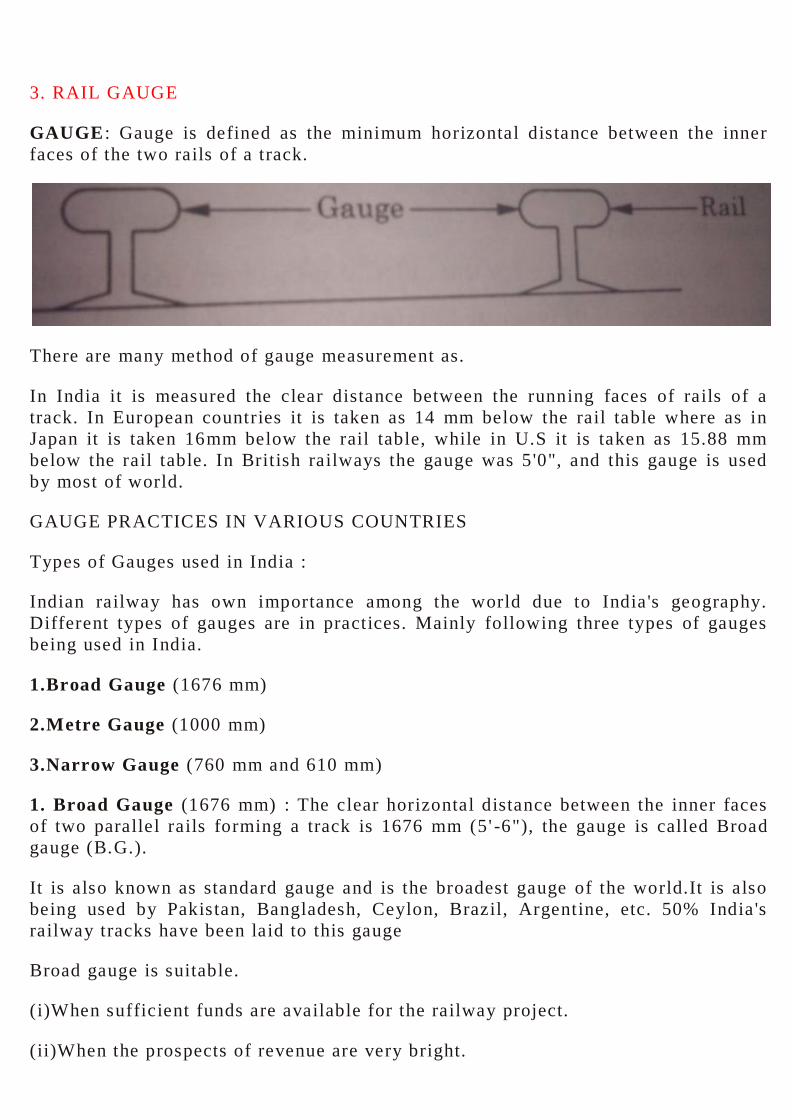
3. RAIL GAUGE
GAUGE : Gauge is defined as the minimum horizontal distance between the inner
faces of the two rails of a track.
There are many method of gauge measurement as.
In India it is measured the clear distance between the running faces of rails of a
track. In European countries it is taken as 14 mm below the rail table where as in
Japan it is taken 16mm below the rail table, while in U.S it is taken as 15.88 mm
below the rail table. In British railways the gauge was 5'0", and this gauge is used
by most of world.
GAUGE PRACTICES IN VARIOUS COUNTRIES
Types of Gauges used in India :
Indian railway has own importance among the world due to India 's geography.
Different types of gauges are in practices. Mainly following three types of gauges
being used in India.
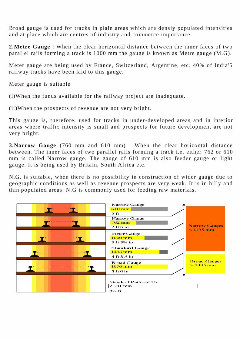
1.Broad Gauge (1676 mm)
2.Metre Gauge (1000 mm)
3.Narrow Gauge (760 mm and 610 mm)
1. Broad Gauge (1676 mm) : The clear horizontal distance between the inner faces
of two parallel rails forming a track is 1676 mm (5' -6"), the gauge is called Broad
gauge (B.G.).
It is also known as standard gauge and is the broadest gauge of the world.It is also
being used by Pakistan, Bangladesh, Ceylon, Brazil, Argentine, etc. 50% India 's
railway tracks have been laid to this gauge
Broad gauge is suitable.
(i)When sufficient funds are available for the railway project.
(ii)When the prospects of revenue are very bright.
Broad gauge is used for tracks in plain areas which are densly populated intensities
and at place which are centres of industry and commerce importance .
2.Metre Gauge : When the clear horizontal distance between the inner faces of two
parallel rails forming a track is 1000 mm the gauge is known as Metre gauge (M.G).
Meter gauge are being used by France, Switzerland, Argentine, etc. 40% of India '5
railway tracks have been laid to this gauge.
Meter gauge is suitable
(i)When the funds available for the railway project are inadequate.
(ii)When the prospects of revenue are not very bright.
This gauge is, therefore, used for tracks in under -developed areas and in interior
areas where traffic intensity is small and prospects for future development are not
very bright.
3.Narrow Gauge (760 mm and 610 mm) : When the clear horizontal distance
between. The inner faces of two parallel rails forming a track i.e. either 762 or 610
mm is called Narrow gauge. The gauge of 610 mm is also feeder gauge or light
gauge. It is being used by Britain, South Africa etc.
N.G. is suitable, when there is no possibility in construction of wider gauge due to
geographic conditions as well as revenue prospects are very weak. It is in hilly and
thin populated areas. N.G is commonly used for feeding raw materials.
Uniformity of Gauges
Uniformity of gauge means uniform gauge throughout the country
It is very important aspect of construction that uniformity of gauge is economical.
This system is highly beneficial to the rail uses.
Gauge to he used in a particular country should be uniform as far as possible,
Because it will avoid difficulties experienced in a non -uniform system and will
result in he following advantages :
1. The delay, cost and hardship in transshipping passengers and goods from the
vehicles of one gauge to another is avoided.
2. Transshipping is not required, so there is no breakage of goods.
3. Loading and unloading is avoided and labour expenses are saved.
4. Chances of thefts and misplacement, are nil because there is no transshipping.
5. Sheds to store goods are not required.
6. Labour strikes, etc. do not affect the service and operation of trains.
7. Surplus wagons of one gauge cannot be used on another gauge. This problem will
not arise if gauge is uniform.
8. Locomotive can be used on all the tracks if a uniform type of gauge is adopted.
9 Duplication of platforms, sanitary arrangements, clocks, etc. is avoided, Thus
saves extra expenditure.
10. Military movement during emergency, no time is wasted in changing personnel
and equipment if gauge is uniform.
11. It is quire expensive to convert one gauge into another at a later stage as it may
require new rolling stock, fresh construction and widening of bridges and tunnels.
etc.
12. In uniform gauge this the late arrival of trains is prohibited upto large extend.
13. Porter charges are increased when passengers have to changes compartment due
to a different gauge. This is avoided if gauge is uniform.
4. RAILS
RAILS
"Rails may be defined as the rolled steel sections laid in two parallel lines over the
sleepers to form the track are known as rails."
Rails are the main part of permanent way on which wheels of rolling stock move.
These are continuous girders which carry axle load.
FUNCTIONS OF RAILS
Rails in the railway track serve the following purpose :
(i) Rails provide a hard, smooth surface for passage of heavy moving loads with a
minimum friction between the rails and wheels.
(ii) Rails bear the stresses developed due to heavy vertical loads, lateral and
braking forces and thermal stresses.
(iii) The rail material gives minimum wear to rails.
(iv) Rails transmit load to sleepers and consequently reduce p ressure on ballast and
formation.
COMPOSITION OF RAIL STEEL
1) For Ordinary Rails : High carbon steel with following composition is used :
Carbon (C) - 0.55 to 0.6 percent.
Manganese (Mn) - 0.65 to 0.90 percent
Silicon (Si) - 0.05 to 0.3 percent
Sulphur (S) - 0.05 per cent or below
Phosphorus (P) - 0.05 per cent or below.
(ii) For Rails on points and crossing : Medium carbon steel With following
composition is used :
Carbon (C) - 0.5 to 0.6 percent
Manganese (Mn) - 0.95 to 1.25 percent
Silicon (Si) - 0.05 to 0.203 percent
Sulphur (S) 0.06 %
TYPES OF RAILS
The rails which are used for railway track should be such that every part of the rail
can withstand against maximum allowable stress. The design/cross sectional area of
rail should be economical. There are three types of rails are used in the construction
of a railway track
1.Double headed rails.
2.Bull headed rails.
3.Flat footed rails.
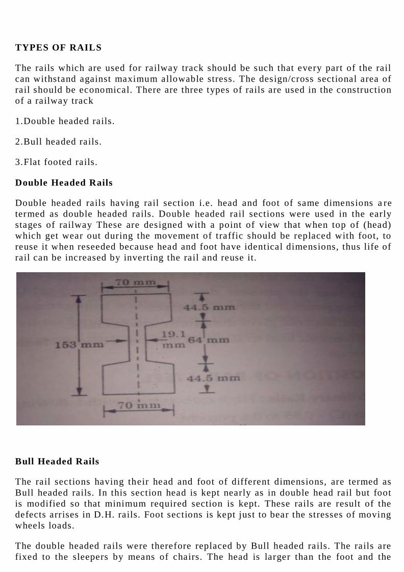
Double Headed Rails
Double headed rails having rail section i.e. head and foot of same dimensions a re
termed as double headed rails. Double headed rail sections were used in the early
stages of railway These are designed with a point of view that when top of (head)
which get wear out during the movement of traffic should be replaced with foot, to
reuse it when reseeded because head and foot have identical dimensions, thus life of
rail can be increased by inverting the rail and reuse it.
Bull Headed Rails
The rail sections having their head and foot of different dimensions, are termed as
Bull headed rails. In this section head is kept nearly as in double head rail but foot
is modified so that minimum required section is kept. These rails are result of the
defects arrises in D.H. rails. Foot sections is kept just to bear the stresses of moving
wheels loads.
The double headed rails were therefore replaced by Bull headed rails. The rails are
fixed to the sleepers by means of chairs. The head is larger than the foot and the
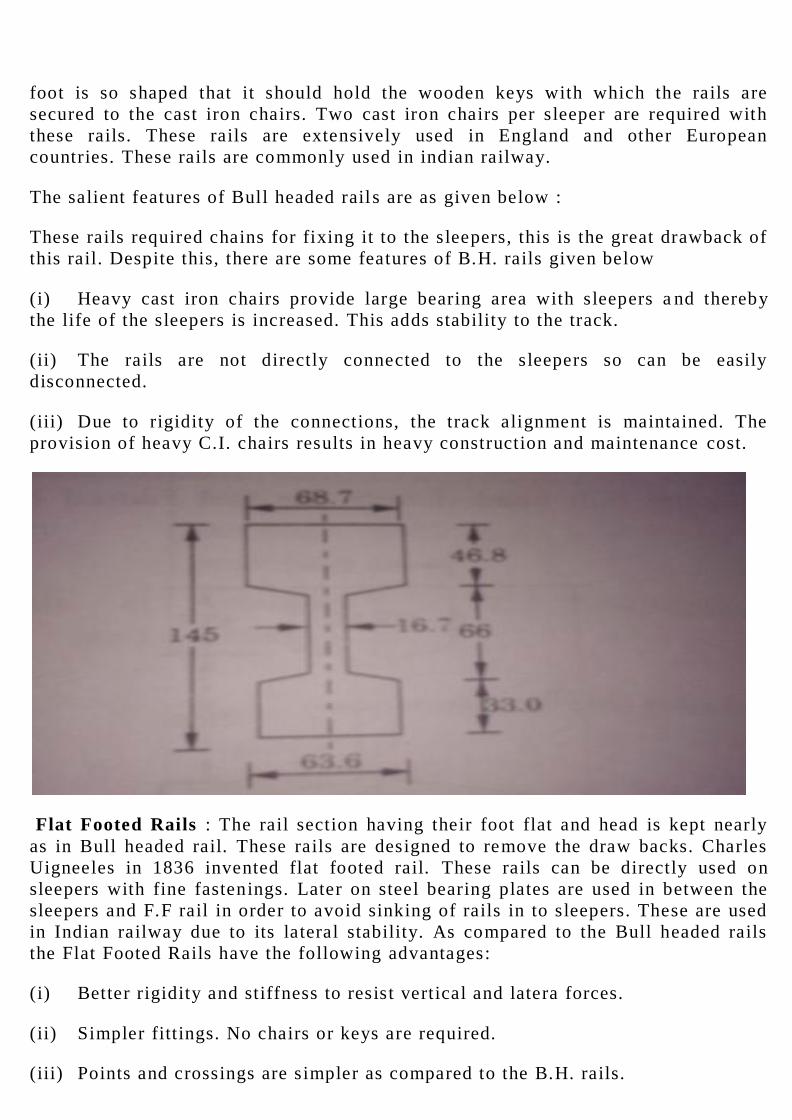
foot is so shaped that it should hold the wooden keys with which the rails are
secured to the cast iron chairs. Two cast iron chairs per sleeper are required with
these rails. These rails are extensively used in England and other European
countries. These rails are commonly used in indian railway.
The salient features of Bull headed rail s are as given below :
These rails required chains for fixing it to the sleepers, this is the great drawback of
this rail. Despite this, there are some features of B.H. rails given below
(i) Heavy cast iron chairs provide large bearing area with sleepers a nd thereby
the life of the sleepers is increased. This adds stability to the track.
(ii) The rails are not directly connected to the sleepers so can be easily
disconnected.
(iii) Due to rigidity of the connections, the track alignment is maintained. The
provision of heavy C.I. chairs results in heavy construction and maintenance cost.
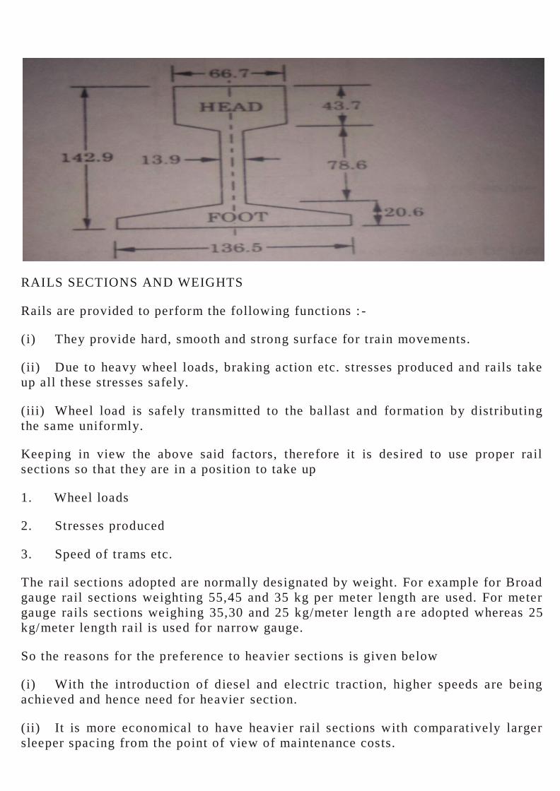
Flat Footed Rails : The rail section having their foot flat and head is kept nearly
as in Bull headed rail. These rails are designed to remove the draw backs. Charles
Uigneeles in 1836 invented flat footed rail. These rails can be directly used on
sleepers with fine fastenings. Later on steel bearing plates are used in between the
sleepers and F.F rail in order to avoid sinking of rails in to sleepers. These are used
in Indian railway due to its lateral stability. As compared to the Bull headed rails
the Flat Footed Rails have the following advantages:
(i) Better rigidity and stiffness to resist vertical and latera forces.
(ii) Simpler fittings. No chairs or keys are required.
(iii) Points and crossings are simpler as compared to the B.H. rails.
RAILS SECTIONS AND WEIGHTS
Rails are provided to perform the following functions : -
(i) They provide hard, smooth and strong surface for train movements.
(ii) Due to heavy wheel loads, braking action etc. stresses produced and rails take
up all these stresses safely.
(iii) Wheel load is safely transmitted to the ballast and formation by distributing
the same uniformly.
Keeping in view the above said factors, therefore it is desired to use proper rail
sections so that they are in a position to take up
1. Wheel loads
2. Stresses produced
3. Speed of trams etc.
The rail sections adopted are normally designated by weight. For example for Broad
gauge rail sections weighting 55,45 and 35 kg per meter length are used. For meter
gauge rails sections weighing 35,30 and 25 kg/meter length a re adopted whereas 25
kg/meter length rail is used for narrow gauge.
So the reasons for the preference to heavier sections is given below
(i) With the introduction of diesel and electric traction, higher speeds are being
achieved and hence need for heavier section.
(ii) It is more economical to have heavier rail sections with comparatively larger
sleeper spacing from the point of view of maintenance costs.
(iii) The depression between two sleepers is less in the case of heavier rails and
hence less pulling power is required for traction.
(iv) The selection of the rail to be adopted in a particular case are governed by the
following factors
(i) Gauge of the track.
(ii) Axle load and nature of traffic.
(iii) Spacing of sleepers.
(iv) Speed of the train.
(v) Availability of standard section.
LENGTH OF RAILS
From the view of maintenance cost and efficient functioning of the track the longer
the rail, the better it is. Long rails have less number of joints and hence lesser
fittings which result in reduction in the cost of construction and maintenance.
Longer rails also provide a better travel comfort to the passengers as the less
number of joints results insmooth running of the train. The length of the rail is
therefore limited by the following consideration :
(i) Facility for economical length from the point of view of its manufacture
(ii) Facility for being transported by wagons.
(iii) Facility for lifting and handling of the rail.
(iv) Provision of expansion joints.
Taking the above factors into consideration the Indian Railways adopted 12.8
metres (42 feet) and 11.89 metres (39 feet) as standard rail lengths for the Broad
Gauge (B.G.) and Metre Gauge (M.G.) respectively. The standard rail lengths
adopted in America, England, France and Germany are 11.89 metres, 1 8.30 metres,
24 metres and 30 metres respectively.
RAIL CORRUGATION
The appearance of weavy surface on the head of rail is termed as rail corrugation.
Corrugation is the result due to defects in the laying out or defects in maintenance
of the track, or due to steep gradient of the resulting in sudden application of
brakes, the heads of the rails develop a wavy surface. Rails which develop this
defect are known as Corrugated Rails. When the trains pass over such rails, a '
roaring noise is created and for this reason these rails are known as Roaring Rails
as well.
These defects generally develop in the following rail locations :
(i) At starting and terminating points of the track due to braking action.
(ii) On electrified sections due to high speeds.
(iii) In long tunnels due to presence of humidity.
(iv) On yielding formations or rails laid on soft material like brick ballast.
The development of corrugations in rail results in overall deterioration of the track.
It also loosens rail fastenings, fittings and an ti creep devices.
How to avoid corrugation ?
The only remedy for rail corrugations is to grind the corrugation by special
machines. In India corrugated rails are replaced by new rails.
CORROSION OF RAILS
The gradually destruction of rails in the presence of dampness is called corrosion of
rails.
It is eating away of rails or wasting away of rails in the presence of damp condition.
The presence of damp conditions causes corrosion of rails. The effect is seen
particularly in tunnels, near ash-pits and in the vicinity of industrial areas. As a
result of this corrosion, the strength of the rail is reduced because of reduction in
effective resisting area. If immediate remedial treatment is not given to the rails the
strength of the rail may get reduced to such a n extent that it may lead to failure of
the rail.
The prevention of this defect can be done either by using specially fabricated rails
prepared from special steel alloy or by coating the surface with non -corrosive
material. The practice in Indian Railways is to apply one coat of zinc chromate over
a red oxide priming coat. The surface is finished with three coats of bituminous
emulsion.
Coning of Wheels : If the distance between the inside edge of the flanges is kept
equal to the gauge distance the flanges of the wheel would rub against the inside
face of the rail. To prevent this the distance between the inside edge of the flanges
is kept less than the gauge distance.
If the rim of the wheels rests flat on the rails there would be lateral movement of
the axle resulting in damage to the inside edge of the rails. This is prevented by
sloping the wheels at a slope of 1 in 20 as shown in Fig. The foot of the rail resting
on the sleeper is also tilted to a slope of 1 in 20. This sloping of the wheel from the
vertical axis is known as CONING OF WHEELS.
When the wheel negotiates a curve, the outer wheel has to cover a greater distance
than the inner wheel. The axile therefore shifts laterally towards the outer rail and
since there is coning of the wheels, the tread at outer rail increases and that at the

inner rail decreases. The outer wheel therefore is able to cover the additional
distance without any 's lipping' taking place.
One of the undesired effects of 'Coning of wheels ' is that the pressure of the wheel
is always towards the inner edge of the rail.
WELDING OF RAILS
Welding is the process of uniting the similar metals. A railway track which consists
of rail were rolled in short lengths due to difficulties in rolling and transportation
operations. The rail jo int is the weakest section of the rail and is unavoidable. The
lengths of the rails can be increased by welding the rail joints.
Purposes
(i) To increases the length of rail thus reduce the number of joints which leads
the economy.
(ii) To restore the worn out or damaged rail section.
(iii) To repair damaged or worn out points and rails along the curves.
(iv) To restore the burnt sections of head of the rail or to repair any other defect.
Advantage of Welding of Rails
1. Reduction in the number of joints resulting in saving in construction and
maintenance cost.
2. Increase in the life of the rail due to reduction in wear at the end.
3. Increased travelling comfort due to reduction of joints.
4. Reduction in creep.
5. Increase in carrying capacity of the track.
6. Saving in fuel due to reduction in tractive effort.
7. Reduction in theft and sabotage.
8. Increase in the stability and stiffness of the track.
METHODS OF WELDING OF RAILS
1. Electric arc welding.
2. Oxy- acetylene welding
3. Flash butt welding.

4. Chemical or thermit welding.
These methods are briefly described below
1. Electric Arc Welding : Heat is generated by passage of an electric current across
a gap between two conductors. A metal electrode is energised by an electric voltage
and brought close to another metal object. This produces an arc of electric current.
The heat generated in the process causes fusion of the two rail ends which get
welded. This method can be used only in the workshop where facilities of electric
current are available. Because of the evident limitations, this method is not popular
with Indian Railways.
2.Oxy-Acetylene Welding : The heat required for welding is produced by the
combination of oxygen and acetylene gas and hence the name of the process. The
rail ends to be welded are brought in contact and heat is applied through a blow
pipe which connects the oxygen and acetylene gas cylinders. The rail metal at the
ends melts and fusion takes place at a temperature of 3300°C. The weld produced
by this method is not very satisfactory and hence the method is not popular in
Indian Railways, for welding the rail joints.
3. Flash Butt Welding : In this method the two rails to be welded are clamped into
two jaws of the welding machine. The gap between the two rail ends is adjusted by
adjusting the rail held by the movable jaw. The other jaw of the machine is
stationary. The rail ends are brought near each other. An electric current of about 5
volts and 35,000 amperes is allowed to pass between the inner faces of the two
rails. The passage of electric current generates lot of heat at the rail ends. The ends
of the rails are moved to and fro till the fusion temperature of 1000°C to 1500°C is
reached. At this stage a pressure of about 37 tonnes is applied and the rails get
pressed together. The process is so regulated that any steel which may be oxidised
during preheating is eliminated. The time taken for welding each set of rails is from
2.5 to 3.3 minutes and upto 20 mm length of rail is lost in each weld. As compared
to other methods of welding the cost of welding by this method is less and the
quality of the weld is very good.
4.Chemical or Thermit Welding of Rails : This method was first developed by
Gold Schmidt of Germany towards the end of 19th century.
When a mixture of finely d ivided Aluminium and Iron oxide known as THERMIT
mixture" is ignited, a chemical action takes place. Heat is produced during this
reaction and iron and aluminium oxides are formed
Fe203 + 2A1= Al203 + 2Fe + Heat
The iron released from the reaction is in a molten state. This molten iron welds the
rail ends which are kept enveloped by mould boxes. The aluminium oxide being
lighter floats on top and forms slag.
WEAR OF RAILS
The gradual reduction in cross -sectional dimensions of rail is called wear of rail.
Wear of rail occurs due to heavy loads move on rails with high speeds, Due to these
movements of wheel loads the rails gets worn off. This wear is also the result of
weather conditions like temperature, sand, snow, and rain, maintenance of track
also cause vertical and lateral wear on rails. Therefore wear of rails can be
classified keeping in view the location and position of wear.
Location of Wear
1. Where steep gradient is provided.
2. On curves.
3. Near railway stations, where acceleration and de -acceleration has to take place.
4. Near sea and Industrial areas due to saltish water.
5. In tunnels due to gases.
6. Track sections where maintenance is not proper .
Position of Wear
On straight and curved tracks the rails may get worn off near
(a) Heads of Rails
(b) Ends of Rails
(c) Sides of Rails
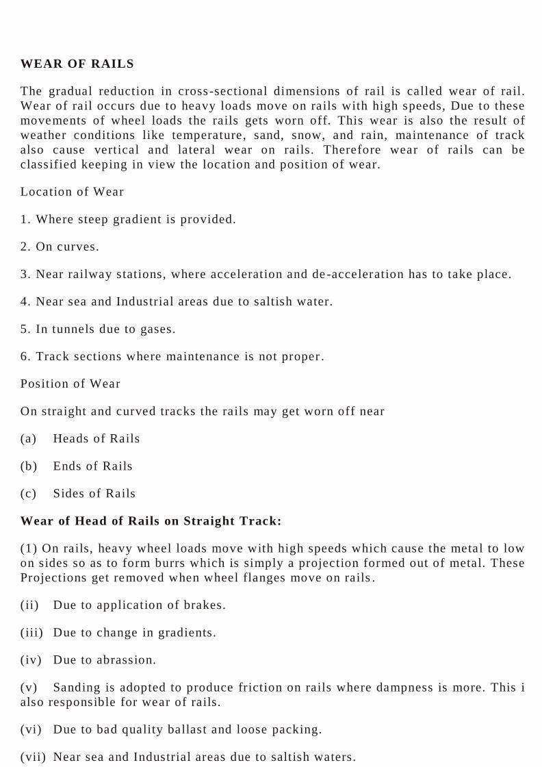
Wear of Head of Rails on Straight Track:
(1) On rails, heavy wheel loads move with high speeds which cause the metal to low
on sides so as to form burrs which is simply a projection formed out of metal. These
Projections get removed when wheel flanges move on rails .
(ii) Due to application of brakes.
(iii) Due to change in gradients.
(iv) Due to abrassion.
(v) Sanding is adopted to produce friction on rails where dampness is more. This i
also responsible for wear of rails.
(vi) Due to bad quality ballast and loose packing.
(vii) Near sea and Industrial areas due to saltish waters.
(a) Wear of Head of Rails on Curved Tracks
(1) Due to skidding of wheels— when the wheels travel linear distance without
revolving.
(ii) Due to slipping of wheels— when the wheels travel no linear distance however
they go on revolving.
(iii) Due to less area of contact between the wheels and rails, while providing
super elevation, some mistake is committed while providing proper tilt.
(iv) When the amount of super elevation provided is less or more than the require
amount.
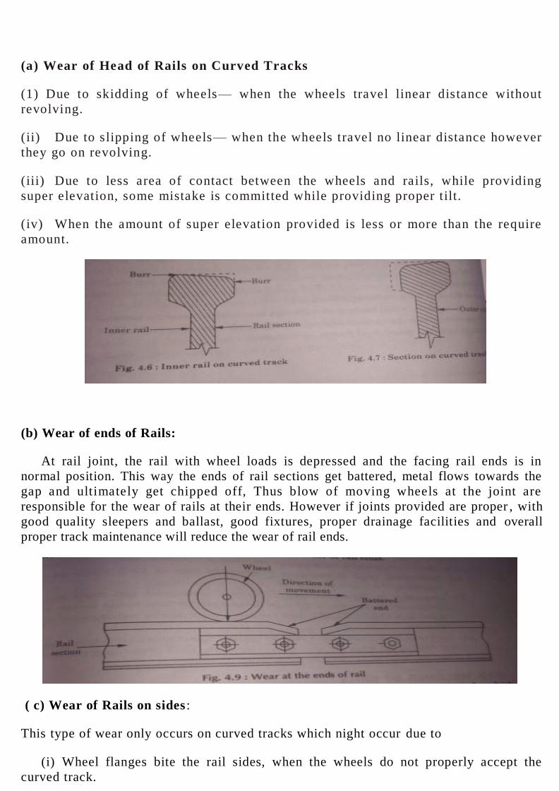
(b) Wear of ends of Rails:
At rail joint, the rail with wheel loads is depressed and the facing rail ends is in
normal position. This way the ends of rail sections get battered, metal flows towards the
gap and ultimately get chipped off, Thus blow of moving wheels at the joint are
responsible for the wear of rails at their ends. However if joints provided are proper , with
good quality sleepers and ballast, good fixtures, proper drainage facilities and overall
proper track maintenance will reduce the wear of rail ends.
( c) Wear of Rails on sides :
This type of wear only occurs on curved tracks which night occur due to
(i) Wheel flanges bite the rail sides, when the wheels do not properly accept the
curved track.
(ii) Due to the centrifugal forces flanges rub on the inner side of the outer rail.
(iii) Slipping of wheels is also responsible for wear of sides of rails.
Methods to Reduce wear of Rails
(i) By providing proper super elevation on curved tracks.
(ii) Coning of wheels to a slope of 1 : 20 and similarly tilting of track rails to till
same slope of 1 : 20 also helps in reducing the wear of rails.
(iii) Use better quality alloy steel rails, where the wear expected is more.
(iv) Give proper gradient to the Railway track which is recommended by I.R.C.
(v) Number of joints be less and in addition to this they should be provide properly
and well maintained.
(vi) Sleepers provided are of good quality and ballast is packed tightly.
(vii) Near the Rail Road crossings, points and crossings and curved tracks, provide,
check-rails where-ever necessary. Widening of gauge also helps.
(viii) Lubricating the jails off and on also reduces the wear of rails.
(ix) By replacing the outer rails by the inner rails on curved tracks.
(x) Maintenance of track should be proper, change the battered and worn our parts.
The following additional measures are taken to reduce the wear.
(a) Satisfactory track maintenance: The main item of track maintenance tightening
of fish bolts at the joints.
(b) Inspection of Expansion Gap : Whereas inadequate gap might lead derailment,
the increase in the gaps beyond certain limit would increase we o f the ends of the
rails. This defect is partly overcome by welding some of the ,rail joints.
(c) Exchange of inner and outer rails on curves : Sometimes there is heavy wean top
head of the inner rail and on the side of the head of the outer rail. In such c ases the
inner and outer rails can be interchanged.
WELDING OF RAILS
These days the rail sections are being welded. Five rails are welded together make a total
length of 64 m. This process not only makes the journey comfortable II passengers but also
reduces the maintenance cost from 20% to 50%.
Purposes and Advantages of Welding of Rails
1. Discomfort of passengers is reduced, as the number of joints is also reduced.
2. Maintenance cost of track is reduced from 20% to 50%.
3. Life of points and crossings is increased.
4. The rail head is burnt at certain places due to slipping of wheels. That portion of
rail head can be repaired by welding.
5. As the rail joint is the weakest part of the track, their number can be reduced by
welding the joints.
6. Creep of rails is also reduced, as the overall expansion reduced and more over
number of joints also gets reduced.
7. On bridges, full rail lengths equal to span can be used. This also reduces the
intensity of high frequency vibrations.
8. Where electrified tracks are used, circuiting of tracks becomes easy due to
welding of rails.
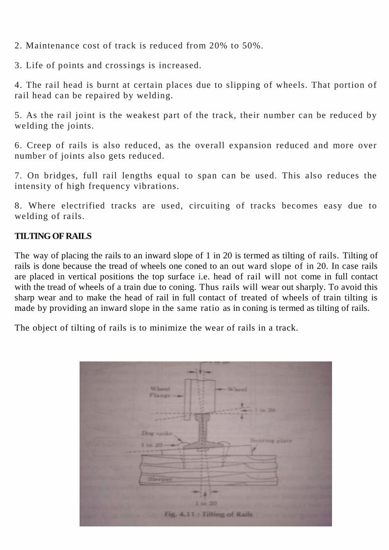
TILTING OF RAILS
The way of placing the rails to an inward slope of 1 in 20 is termed as tilting of rails. Tilting of
rails is done because the tread of wheels one coned to an out ward slope of in 20. In case rails
are placed in vertical positions the top surface i.e. head of rail will not come in full contact
with the tread of wheels of a train due to coning. Thus rails will wear out sharply. To avoid this
sharp wear and to make the head of rail in full contact of treated of wheels of train tilting is
made by providing an inward slope in the same ratio as in coning is termed as tilting of rails.
The object of tilting of rails is to minimize the wear of rails in a track.

Advantages :
(i) The gauge is properly maintained.
(ii) Tilting result the wear of the rail head uniform.
(iii) The life of rails and sleepers increase due to tilting of rails.
FAILURE OF RAILS
The appearance of splits, cracks or fissures in the rails due manufacturing defects
slipping or skidding of wheels etc., is called failure of rails.
The failure of a rail is due to defect in its manufacture, other causes like slipping of
wheels, skidding of wheels, inadequate support at the rail end, etc. may also result failure
of rails. Rails are made under rigid quality control and hence sudden failure, of rails are
very unusual occurrence. When ever it occurs it is purly manufacturing defect.
Type of Failures
As discussed rails are made under stiff quality control, but rail failure may he the result
of following causes
(i) Horizontal cracks : This defect occurs at rail ends, when worn fish plates are used
for joining the rails or when the ballast is not properly packed. The crack develops due to
shearing stresses, at the critical section that is junction between the rail head and the
web. This defect is located on Indian Railways by means of SONIRAIL DETECTOR.
(ii) Horizontal Fissure : It is caused due to defective rail head. The rail develops a
horizontal crack.
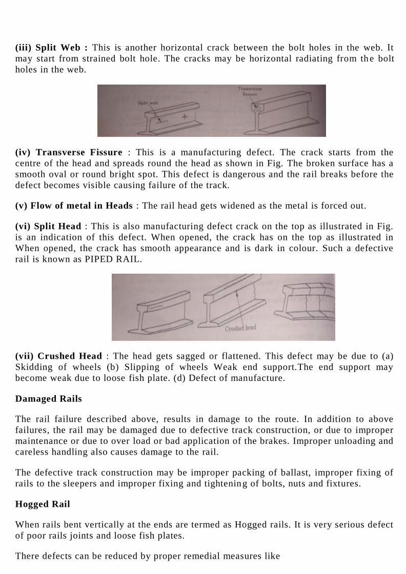
(iii) Split Web : This is another horizontal crack between the bolt holes in the web. It
may start from strained bolt hole. The cracks may be horizontal radiating from th e bolt
holes in the web.
(iv) Transverse Fissure : This is a manufacturing defect. The crack starts from the
centre of the head and spreads round the head as shown in Fig. The broken surface has a
smooth oval or round bright spot. This defect is dangerous and the rail breaks before the
defect becomes visible causing failure of the track.
(v) Flow of metal in Heads : The rail head gets widened as the metal is forced out.
(vi) Split Head : This is also manufacturing defect crack on the top as illustrated in Fig.
is an indication of this defect. When opened, the crack has on the top as illustrated in
When opened, the crack has smooth appearance and is dark in colour. Such a defective
rail is known as PIPED RAIL.
(vii) Crushed Head : The head gets sagged or flattened. This defect may be due to (a)
Skidding of wheels (b) Slipping of wheels Weak end support.The end support may
become weak due to loose fish plate. (d) Defect of manufacture.
Damaged Rails
The rail failure described above, results in damage to the route. In addition to above
failures, the rail may be damaged due to defective track construction, or due to improper
maintenance or due to over load or bad application of the brakes. Improper unloading and
careless handling also causes damage to the rail.
The defective track construction may be improper packing of ballast, improper fixing of
rails to the sleepers and improper fixing and tightening of bolts, nuts and fixtures.
Hogged Rail
When rails bent vertically at the ends are termed as Hogged rails. It is very serious defect
of poor rails joints and loose fish plates.
There defects can be reduced by proper remedial measures like

(i) By replacing the hogged rail
(ii) If hogging is small, it can be rectified by shovel packing.
(iii) The hogged rail can be improved by welding the worn out ends.
(iv) By cutting the rail ends about one meter length and fresh holes are provided for fish
plates.
(v) Hogging can also be reduced by using de-hogging machine.
Buckling of Rails
Buckling of rail means the displacement of track from its original position. Buckling is
the result of excessive compressive forces on the track due to insufficient expansion gaps
in the track. Bucking leads the track out of its original position or alignment.
The following are the main cause of buckling :
(1) Due to excessive creep leads the track out of its original position.
(ii) Due to fish plates being bolted so tight that rail s are not allowed to expand or slip.
(iii) Due to loose fittings.
(iv) Inadequate ballast on track also leads buckling because stresses are not counter
balanced.
(v) Welding of rails on weak track also lead buckling.
Remedial Measures
(i) Numbers of welded rails should be decreased.
(ii) By providing anti creep fastenings to the rails.
(iii) The Ballast, sleeper and rail section should be redesigned.
(iv) Lubrication should be done properly and timely to fish plates, bolts at regular
intervals.
(v) Sufficient expansion gap should be provided between rails joints.
(vi) To allow proper expansion and contraction fish bolts should neither be lighted so
tight nor so loose.
(vii) Proper prevision for steel sleepers should be made.
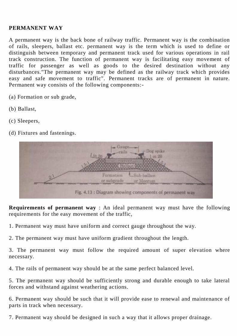
PERMANENT WAY
A permanent way is the back bone of railway traffic. Permanent way is the combination
of rails, sleepers, ballast etc. permanent way is the term which is used to define or
distinguish between temporary and permanent track used for various operations in rail
track construction. The function of permanent way is facilitating easy movement of
traffic for passenger as well as goods to the desired destination without any
disturbances."The permanent way may be defined as the railway track which provides
easy and safe movement to traffic". Permanent tracks are of permanent in nature.
Permanent way consists of the following components:-
(a) Formation or sub grade,
(b) Ballast,
(c) Sleepers,
(d) Fixtures and fastenings.
Requirements of permanent way : An ideal permanent way must have the following
requirements for the easy movement of the traffic,
1. Permanent way must have uniform and correct gauge throughout the way.
2. The permanent way must have uniform gradient throughout the length.
3. The permanent way must follow the required amount of super elevation where
necessary.
4. The rails of permanent way should be at the same perfect balanced level.
5. The permanent way should be sufficiently strong and durable enough to take lateral
forces and withstand against weathering actions.
6. Permanent way should be such that it will provide ease to renewal and maintenance of
parts in track when necessary.
7. Permanent way should be designed in such a way that it allows proper drainage.

8. All the points and crossings among the permanent way must be designed properly and
carefully installed.
9. The permanent way should be designed in such a way that the loads of traffic should
be distributed on both the rails properly.
10. The permanent way must be free from excessive joints.
11. The permanent way must have elastic enough against impacts of moving loads of
traffic.
CREEP OF RAILS
Creep of rails is the result of longitudinal movement of rails with respect to sleepers.
Some times creep may occur due to longitudinally movement with respect to rails. First
type of creep is possible if the toe load of fastenings on the rails is less than the force due
to creep. The sleepers will move longitudinally with the rail if the resistance of the
ballast to such movement is less than the creeping force . The creep behave different
under static and dynamic conditions due to toe load of fastening on the rail foot and the
ballast resistance get considerably reduced because of high frequency vibrations caused
by dynamic loading at high speeds.
"Creep of rails may be defined as the longitudinal movement of rails in a track is known
as creep of rails"
Causes of Creep
The causes of creep are explained by following principal theories: -
1. Wave Action or wave theory
2. Percussion theory
3. Drag theory
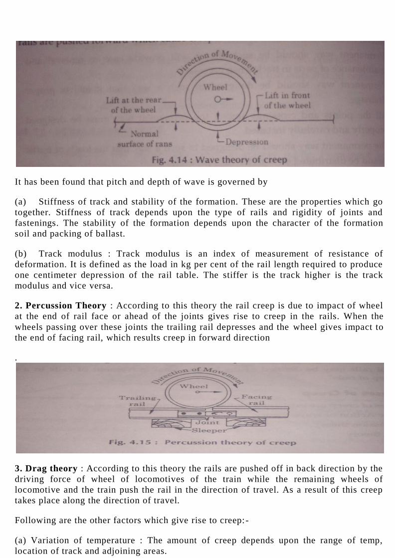
1. Wave action or wave theory : According to this theory, a the rail gets depressed by
the wave motion due to moving wheel loads. The train wheels cause depression under
them forming lifts or crests immediately at the rear and front of the wheel. The wheels
have to push a tendency to push the waves in the direction of traffic, with the successive
forward motion of the wheel the creep is carried forward. Thus the rails are pushed
forward which cause creep in the forward direction.
It has been found that pitch and depth of wave is governed by
(a) Stiffness of track and stability of the formation. These are the properties which go
together. Stiffness of track depends upon the type of rails and rigidity of joints and
fastenings. The stability of the formation depends upon the character of the formation
soil and packing of ballast.
(b) Track modulus : Track modulus is an index of measurement of resistance of
deformation. It is defined as the load in kg per cent of the rail length required to produce
one centimeter depression of the rail table. The stiffer is the track higher is the track
modulus and vice versa.
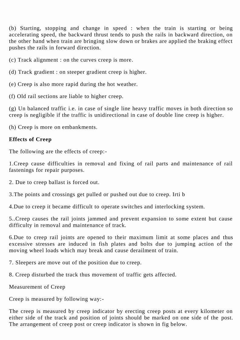
2. Percussion Theory : According to this theory the rail creep is due to impact of wheel
at the end of rail face or ahead of the joints gives rise to creep in the rails. When the
wheels passing over these joints the trailing rail depresses and the wheel gives impact to
the end of facing rail, which results creep in forward direction
.
3. Drag theory : According to this theory the rails are pushed off in back direction by the
driving force of wheel of locomotives of the train while the remaining wheels of
locomotive and the train push the rail in the direction of travel. As a result of this creep
takes place along the direction of travel.
Following are the other factors which give rise to creep:-
(a) Variation of temperature : The amount of creep depends upon the range of temp,
location of track and adjoining areas.
(b) Starting, stopping and change in speed : when the train is starting or being
accelerating speed, the backward thrust tends to push the rails in backward direction, on
the other hand when train are bringing slow down or brakes are applied the braking effect
pushes the rails in forward direction.
(c) Track alignment : on the curves creep is more.
(d) Track gradient : on steeper gradient creep is higher.
(e) Creep is also more rapid during the hot weather.
(f) Old rail sections are liable to higher creep.
(g) Un balanced traffic i.e. in case of single line heavy traffic moves in both direction so
creep is negligible if the traffic is unidirectional in case of double line creep is higher.
(h) Creep is more on embankments.
Effects of Creep
The following are the effects of creep:-
1.Creep cause difficulties in removal and fixing of rail parts and maintenance of rail
fastenings for repair purposes.
2. Due to creep ballast is forced out.
3.The points and crossings get pulled or pushed out due to creep. Irti b
4.Due to creep it became difficult to operate switches and interlocking system.
5..Creep causes the rail joints jammed and prevent expansion to some extent but cause
difficulty in removal and maintenance of track.
6.Due to creep rail joints are opened to their maximum limit at some places and thus
excessive stresses are induced in fish plates and bolts due to jumping action of the
moving wheel loads which may break and cause derailment of train.
7. Sleepers are move out of the position due to creep.
8. Creep disturbed the track thus movement of traffic gets affected.
Measurement of Creep
Creep is measured by following way:-
The creep is measured by creep indicator by erecting creep posts at every kilometer on
either side of the track and position of joints should be marked on one side of the post.
The arrangement of creep post or creep indicator is shown in fig below.
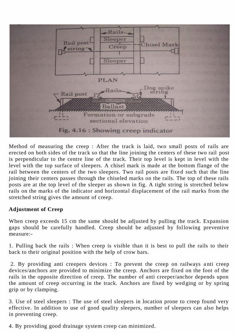
Method of measuring the creep : After the track is laid, two small posts of rails are
erected on both sides of the track so that the line joining the centers of these two rail post
is perpendicular to the centre line of the track. Their top level is kept in level with the
level with the top surface of sleepers. A chisel mark is made at the bottom flange of the
rail between the centers of the two sleepers. Two rail posts are fixe d such that the line
joining their centers passes through the chiseled marks on the rails. The top of these rails
posts are at the top level of the sleeper as shown in fig. A tight string is stretched below
rails on the marks of the indicator and horizonta l displacement of the rail marks from the
stretched string gives the amount of creep.
Adjustment of Creep
When creep exceeds 15 cm the same should be adjusted by pulling the track. Expansion
gaps should be carefully handled. Creep should be adjusted by fol lowing preventive
measure:-
1. Pulling back the rails : When creep is visible than it is best to pull the rails to their
back to their original position with the help of crow bars.
2. By providing anti creepers devices : To prevent the creep on railways a nti creep
devices/anchors are provided to minimize the creep. Anchors are fixed on the foot of the
rails in the opposite direction of creep. The number of anti creeper/anchor depends upon
the amount of creep occurring in the track. Anchors are fixed by wed ging or by spring
grip or by clamping.
3. Use of steel sleepers : The use of steel sleepers in location prone to creep found very
effective. In addition to use of good quality sleepers, number of sleepers can also helps
in preventing creep.
4. By providing good drainage system creep can minimized.

5. By using good quality and sufficient of ballast can also helps in preventing creep.
6. Creep can also be minimized or prevented by proper maintenance of joints.
5. RAILS FASTENINGS:
The devices which are used to make connections between rails to rail as well a s, to fix
the rails to sleepers to make track to fulfill technical aspects are termed as fixtures and
fastenings.
The fixtures are used to make to make connections between rail to rail to rail sleeper to
fix the rail track are termed as fixtures. e.g. spikes, bolts, keys. There are used to fix the
fastenings with rail and sleepers to get track. On the other hand the fastening s which are
bearing plates, fish plates, chairs. etc which are used to fix the rail to rail and to fix to
sleepers to form in full length of rail is terms of track.
Functions:
1. To achieve required tilt of rails.
2. To fix the rails to sleepers.
3. To maintain gauge.
4. To maintain rail alignment.
5. To maintain properly the rail joints .
TYPES OF FIXTURES AND FASTENINGS
: These are classified as
1. Fish plates
2. Bearing plates
3. Chairs.
4. Fastening
(1) Spikes
(ii) Bolts
(iii) Keys and cotters.
(iv) Anchors and anti-creepers.
(A) Fixtures : These are described as.
(1) FISH PLATES : Fish plates is the device which used to maintain the lull length of
rail by joining the rails end to end with M.S. plates are called fish plates.
The fish plates are so designed that they fit the underside of rail head and the top of the
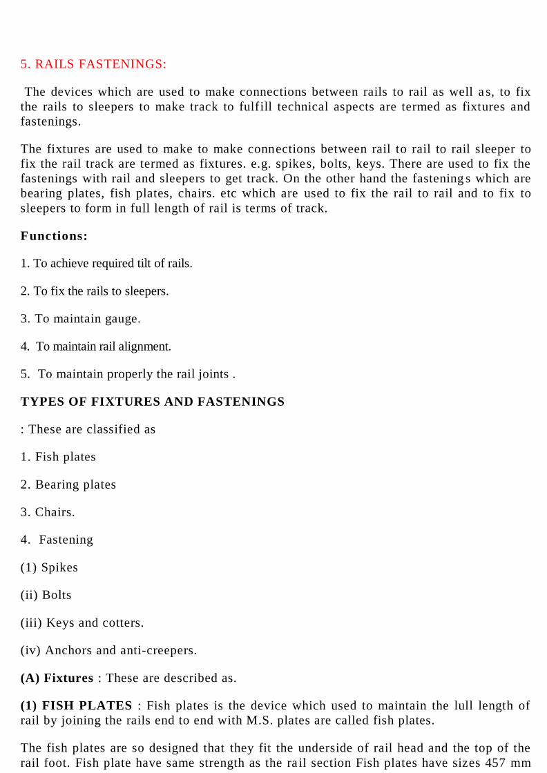
rail foot. Fish plate have same strength as the ra il section Fish plates have sizes 457 mm
long with four numbers 31.70 mm dia holes 114 mm c/c, the depth of the fish plate is
equal to depth of web of the rail.
Functions of Fish Plates
Following are the functions of fish plates in a railway track :
(i) To maintain continuity of rails in a track
(ii) Allow expansion and contraction of the rails due to temperature variations.
(iii) Helps in maintaining the alignment of track and rail joints.
(iv) These helps in renewal and replacement of rails.
Types of Fish Plates
Fish plates are manufactured so as to join the flat footed (F.F) as well as headed (B.H)
rails sections, so broadly these are of the two types.
(1) Bone shaped fish plates.
(ii) Increased depth fish plates.
(1) Bone Shaped Fish Plates : These are used for connecting F. Footed rails, can take the
stresses due to impact of moving wheel loads.

(ii) Increased depth fish plates : These fish plate with increased depth are used for
connecting B.H rails. These provides good stiffness to the rail joints.
Requirements of Fish Plates :
1.The fish plates such that they provide perfect Joint both vertically as well as
horizontally.
Rails Fastenings Fish plates should be such that they properly fit in the webs of adjoining
rails at each rail joint.
3. The fish plates should be such that they allow free expansion and contraction of rails
at rail joints.
4. They should able to resist all types of near.
5. These should provide easy replacement and renewal of rails.

Fish plates should be designed in such a way that they helps in maintaining the alignment
of track.
The most important requirement of fish plate is that it should provide strength to the rail
joints.
(ii) Bearing Plates
The plates which are used to prevent the sinking of flat footed rails in to the wooden
sleepers due to heavy loads are termed as bearing plates.
Advantages
1. They increase the bearing area time distribute the intensity of loads uniformly.
2. There helps in maintaining gauge of the track.
3. Bearing plates increase the life of wooden sleepers.
4. There keeps the spikes and keys remain tight thus helps in smooth movements of
trains.
5. These prevent rail cutting of the sleepers due to rubbing action of rails at seat.
6. These plates provide better alignment at curves.
(iii) CHAIR: Chair is the device which are used to hold the rails to fix in position with
sleeper.
FASTENINGS : These are described below
(i) SPIKES : Spikes are the fixing devices which are used to fix the rails, bearing plates
and chairs to the wooden sleepers. Following are the characteristics of good spikes:
(i) They should be cheep and easily available.
(ii) They should be strong enough to hold the rails, bearing plates, and chair in position.
(iii) They should be easy in fixing and removing for easy maintenance of track
Types of Spikes
(I) Dog spikes
(ii) Round spikes
(Iii) Screw spikes
(iv) Elastic spikes
I) Dog Spikes : Dog spikes are named because of their shape of head. There are simple in
shape. This is the cheapest, simple and most efficient spike which holds the rails to the
correct gauge on a Rail Track. These spikes are square in section with lower end pointed
blunt or chiseled shape
They are commonly used where F.F. rails are used due to wave action they become loose
so special care is required towards their maintenance - Firstly holes are bored then they
should be driven.
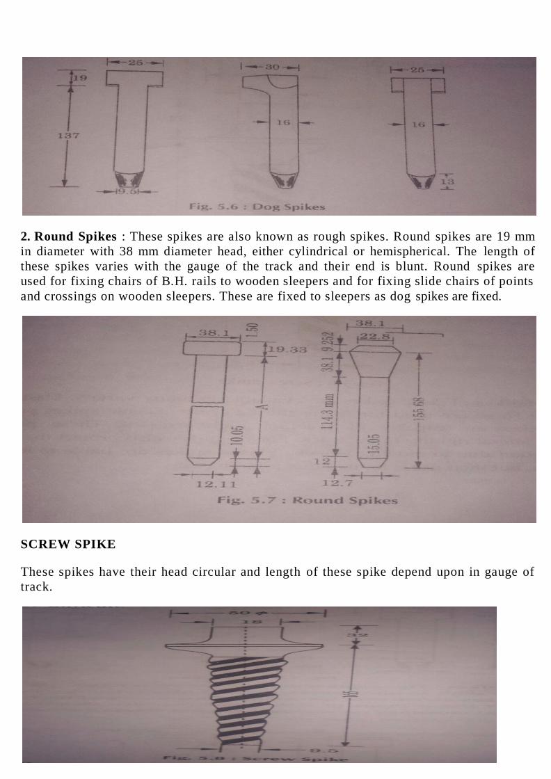
2. Round Spikes : These spikes are also known as rough spikes. Round spikes are 19 mm
in diameter with 38 mm diameter head, either cylindrical or hemispherical. The length of
these spikes varies with the gauge of the track and their end is blunt. Round spikes are
used for fixing chairs of B.H. rails to wooden sleepers and for fixing slide chairs of points
and crossings on wooden sleepers. These are fixed to sleepers as dog spikes are fixed.
SCREW SPIKE
These spikes have their head circular and length of these spike depend upon in gauge of
track.

Elastic Spikes
Elastic spikes are available in many variety. Elastic spikes are of special shape. These are
used for fixing the F.F. rails. Elastic spikes provide better grip, Elastic spikes are capable
of meeting high stresses. These provide or longitudinal and lateral rigidity to the track.
Elastic spikes also protect the track against. shocks and vibration due to moving wheels.
Elastic spike are liable to less creep an' produce low riser, but their use is limited due to
high cost.
Bolts : Bolts art. used for connecting fish plates to the rails at each mil joint, chairs to
sleepers and bearing plates etc. There are different types of bolts available And being
used h Indian railways as per the need these may be classified as
(i) Fish Bolts : These are used to Connect the fish plates to the rails at rail point. Each
pair of fish plate is joined by tour fish bolts, two on either side of the joint These bolts
are very heavily stressed and hence they are made from medium or high carbon steel.
Since they get loosened due to vibrations, they are tightened form- tune to time Over-
tightening however prevents the free expansion of rail and is prohibited
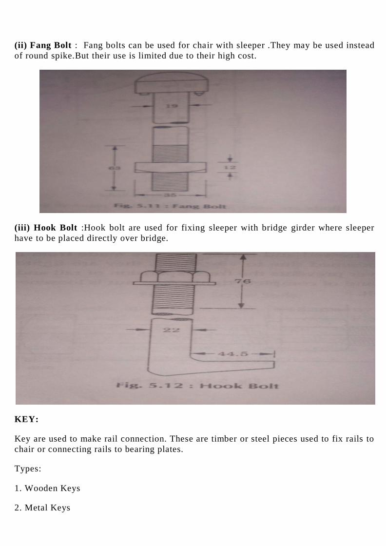
(ii) Fang Bolt : Fang bolts can be used for chair with sleeper .They may be used instead
of round spike.But their use is limited due to their high cost.
(iii) Hook Bolt :Hook bolt are used for fixing sleeper with bridge girder where sleeper
have to be placed directly over bridge.
KEY:
Key are used to make rail connection. These are timber or steel pieces used to fix rails to
chair or connecting rails to bearing plates.
Types:
1. Wooden Keys
2. Metal Keys
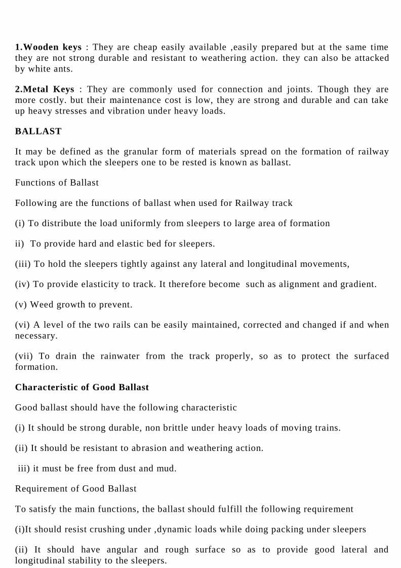
1.Wooden keys : They are cheap easily available ,easily prepared but at the same time
they are not strong durable and resistant to weathering action. they can also be attacked
by white ants.
2.Metal Keys : They are commonly used for connection and joints. Though they are
more costly. but their maintenance cost is low, they are strong and durable and can take
up heavy stresses and vibration under heavy loads.
BALLAST
It may be defined as the granular form of materials spread on the formation of railway
track upon which the sleepers one to be rested is known as ballast.
Functions of Ballast
Following are the functions of ballast when used for Railway track
(i) To distribute the load uniformly from sleepers to large area of formation
ii) To provide hard and elastic bed for sleepers.
(iii) To hold the sleepers tightly against any lateral and longitudinal movements,
(iv) To provide elasticity to track. It therefore become such as alignment and gradient.
(v) Weed growth to prevent.
(vi) A level of the two rails can be easily maintained, corrected and changed if and when
necessary.
(vii) To drain the rainwater from the track properly, so as to protect the surfaced
formation.
Characteristic of Good Ballast
Good ballast should have the following characteristic
(i) It should be strong durable, non brittle under heavy loads of moving trains.
(ii) It should be resistant to abrasion and weathering action.
iii) it must be free from dust and mud.
Requirement of Good Ballast
To satisfy the main functions, the ballast should fulfill the following requirement
(i)It should resist crushing under ,dynamic loads while doing packing under sleepers
(ii) It should have angular and rough surface so as to provide good lateral and
longitudinal stability to the sleepers.
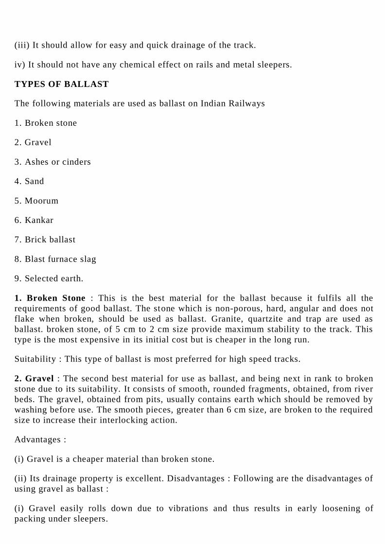
(iii) It should allow for easy and quick drainage of the track.
iv) It should not have any chemical effect on rails and metal sleepers.
TYPES OF BALLAST
The following materials are used as ballast on Indian Railways
1. Broken stone
2. Gravel
3. Ashes or cinders
4. Sand
5. Moorum
6. Kankar
7. Brick ballast
8. Blast furnace slag
9. Selected earth.
1. Broken Stone : This is the best material for the ballast because it fulfils all the
requirements of good ballast. The stone which is non-porous, hard, angular and does not
flake when broken, should be used as ballast. Granite, quartzite and trap are used as
ballast. broken stone, of 5 cm to 2 cm size provide maximum stability to the track. This
type is the most expensive in its initial cost but is cheaper in the long run.
Suitability : This type of ballast is most preferred for high speed tracks.
2. Gravel : The second best material for use as ballast, and being next in rank to broken
stone due to its suitability. It consists of smooth, rounded fragments, obtained, from river
beds. The gravel, obtained from pits, usually contains earth which should be removed by
washing before use. The smooth pieces, greater than 6 cm size, are broken to the required
size to increase their interlocking action.
Advantages :
(i) Gravel is a cheaper material than broken stone.
(ii) Its drainage property is excellent. Disadvantages : Following are the disadvantages of
using gravel as ballast :
(i) Gravel easily rolls down due to vibrations and thus results in early loosening of
packing under sleepers.

(ii) The variation in size and quality is considerable and hence, it requires screening of
small size fragment, .breaking of large size and smooth pieces and washing of gravel
obtained from pits.
Suitability : This type of ballast is also used in large quantity in India and other
countries.
3. Ashes or cinders : The residue obtained form coal used is known as ash
It is a by-product of every railway, using coal as fuel. It is preferred being economic al
ballast material in its initial cost, available in large quantity When eve required, has
excellent drainage properties, and provides easy handling. In emergency such as
destruction of track by floods, this can be used for repairing formation as well for
packing track. This is suitable for station yards, sidings, foot paths. But it should not be
used in main lines because it is very soft and turns in powder under loads and having
corrosive properties thus carried steel sleepers and for rails.
4. Sand : It is also good material for ballast. If no other material is available for some
unimportant track, then sand or some selected type of earth may he tried as ballast
material. It is cheap, easily available but of poor strength and with poor drainage
properties.
These type of ballast is good for packing pet sleepers.
5. Moorum : It is formed by decomposition of lateral. It has red o r yellow color it is soft
ballast material it can be used formerly track, it has good drainage properly. moorum is
used for unimportant tracks because it is soft in nature and turns in powder also
maintenance of rack, laid with moorum is difficult, so it should be used for unimportant
tracks.
6. Kankar : It is a lime agglomerate and is commonly found in certain clayey soil. It is
found in many places in the form of nodules of varying size, where stone is not available
it is being used as ballast because Kankar is a cheap variety of ballast. It has good
drainage characteristics.
7. Bricks Ballast: Where no stone or substitute is available for use as ballast, over burnt
brick are broken into small size and used, It powders easily and produces dusty rack.
Rails in tracks laid on brick ballast many a time get corrugated. Brick ballast however, is
fairly good for drainage.
8. Blast furnace slag: It is by- product obtained in the manufacture of iron. Slag forms
cheap ballast. Obtain from molten slag ,It has got good drainage properties.
9. Selected earth : There are indurated clay and decomposition rock material which are
used as ballast .these are used as ballast.

6. SLEEPERS
SLEEPERS
Sleepers are the members which are laid under the rails to hold the rails required
gauge as well as to support the rails. Sleepers is the main component of track. These are
laid transversely to the rails.
Functions of Sleepers
1. To support the rails properly.
2. To maintain the gauge distance.
3. To distribute the loads on the formation through ballast.
4. To provide cushion between the rail sections and ballast thus absorbing the shock of
moving loads.
5. To provide easy replacement of rails.
6. To maintain the rail track alignment.
Requirements of and ideal Sleeper
1. Sleepers used for track should be able to maintain proper gauge.
2. Sleepers should be able to provide good bearing area for rails.
3. Sleepers should be such that they can take moving load, and not too heavy that cause
problem in handling and transportation.
4. Sleepers should be durable.
5. Material used for sleepers should be such that it does not get damaged during packing and
tamping process.
6. Sleepers have some scrap value after their rejection which indicate the good quality of
sleepers.
7. The design of sleepers should be such that rails can easily fixed and taken out when need
arise.
TYPES OF SLEEPERS
Indian Railways used various types of sleepers in the formation of track, depending upon the
easily availability of the material and the topography of the area. These are
1. Wooden sleepers
2. Metal sleepers
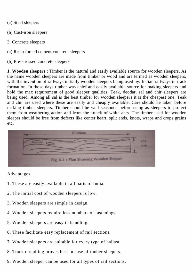
(a) Steel sleepers
(h) Cast-iron sleepers
3. Concrete sleepers
(a) Re-in forced cement concrete sleepers
(b) Pre-stressed concrete sleepers
1. Wooden sleepers : Timber is the natural and easily available source for wooden sleepers. As
the name wooden sleepers are made from timber or wood and are termed as wooden sleepers,
with the invention of railways initially wooden sleepers being used by. Indian railways in track
formation. In those days timber was chief and easily available source for making sleepers and
hold the max requirement of good sleeper qualities. Teak, deodar, sal and chir sleepers are
being used. Among all sal is the best timber for wooden sleepers it is the cheapest one, Teak
and chir are used where these are easily and cheaply available. Care should be taken before
making timber sleepers. Timber should be well seasoned before using as sleepers to protect
them from weathering action and from the attack of white ants. The timber used for wooden
sleeper should be free from defects like center heart, split ends, knots, wraps and crops grains
etc.
Advantages
1. These are easily available in all parts of India.
2. The initial cost of wooden sleepers is low.
3. Wooden sleepers are simple in design.
4. Wooden sleepers require less numbers of fastenings.
5. Wooden sleepers are easy in handling.
6. These facilitate easy replacement of rail sections.
7. Wooden sleepers are suitable for every type of ballast .
8. Track circuiting proves best in case of timber sleepers.
9. Wooden sleeper can be used for all types of rail sections.
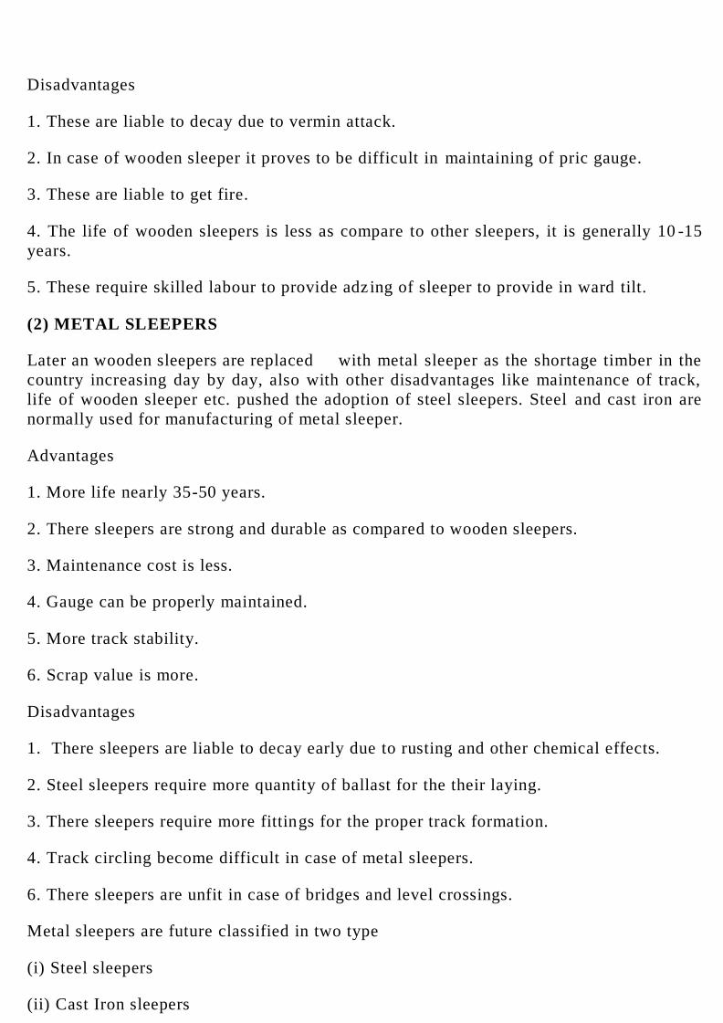
Disadvantages
1. These are liable to decay due to vermin attack.
2. In case of wooden sleeper it proves to be difficult in maintaining of pric gauge.
3. These are liable to get fire.
4. The life of wooden sleepers is less as compare to other sleepers, it is generally 10 -15
years.
5. These require skilled labour to provide adz ing of sleeper to provide in ward tilt.
(2) METAL SLEEPERS
Later an wooden sleepers are replaced with metal sleeper as the shortage timber in the
country increasing day by day, also with other disadvantages like maintenance of track,
life of wooden sleeper etc. pushed the adoption of steel sleepers. Steel and cast iron are
normally used for manufacturing of metal sleeper.
Advantages
1. More life nearly 35-50 years.
2. There sleepers are strong and durable as compared to wooden sleepers.
3. Maintenance cost is less.
4. Gauge can be properly maintained.
5. More track stability.
6. Scrap value is more.
Disadvantages
1. There sleepers are liable to decay early due to rusting and other chemical effects.
2. Steel sleepers require more quantity of ballast for the their laying.
3. There sleepers require more fittings for the proper track formation.
4. Track circling become difficult in case of metal sleepers.
6. There sleepers are unfit in case of bridges and level crossings.
Metal sleepers are future classified in two type
(i) Steel sleepers
(ii) Cast Iron sleepers
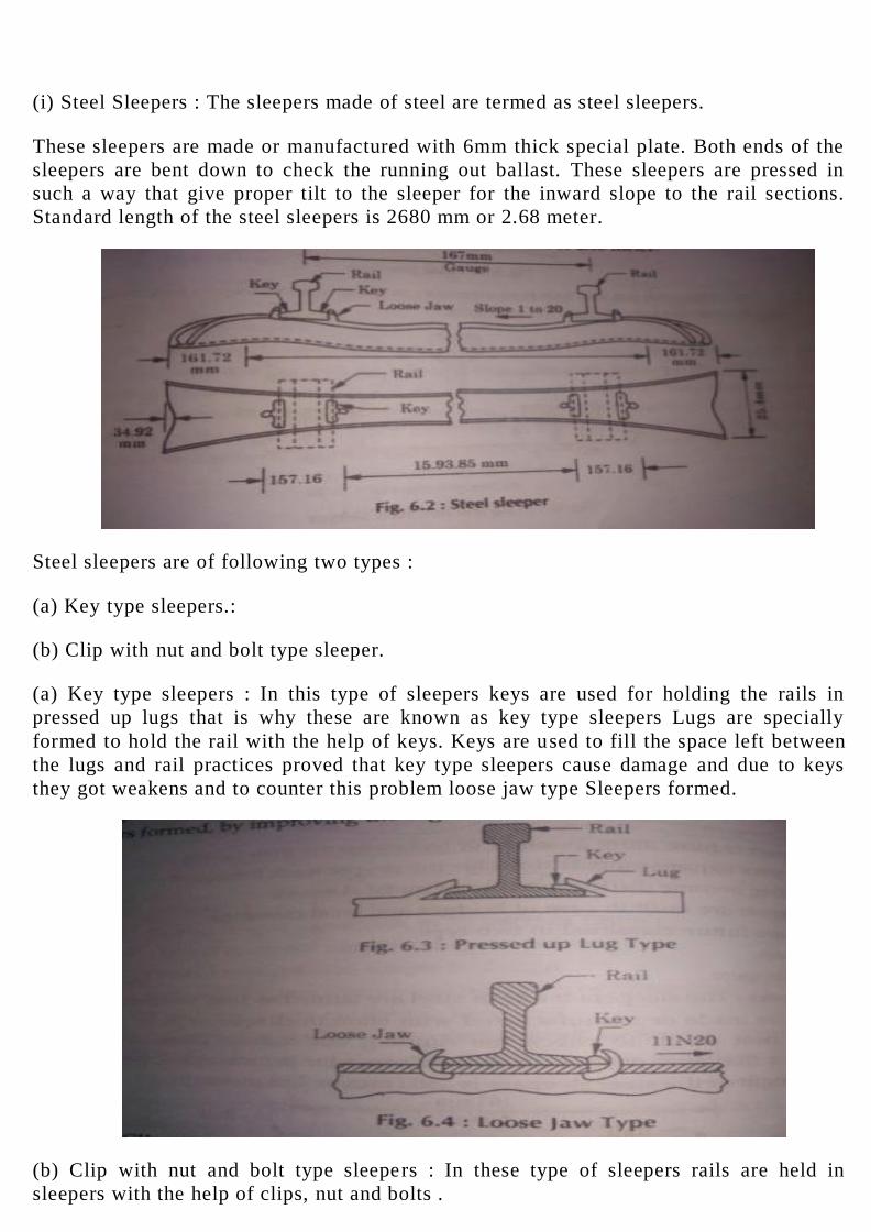
(i) Steel Sleepers : The sleepers made of steel are termed as steel sleepers.
These sleepers are made or manufactured with 6mm thick special plate. Both ends of the
sleepers are bent down to check the running out ballast. These sleepers are pressed in
such a way that give proper tilt to the sleeper for the inward slope to the rail sections.
Standard length of the steel sleepers is 2680 mm or 2.68 meter.
Steel sleepers are of following two types :
(a) Key type sleepers.:
(b) Clip with nut and bolt type sleeper.
(a) Key type sleepers : In this type of sleepers keys are used for holding the rails in
pressed up lugs that is why these are known as key type sleepers Lugs are specially
formed to hold the rail with the help of keys. Keys are used to fill the space left between
the lugs and rail practices proved that key type sleepers cause damage and due to keys
they got weakens and to counter this problem loose jaw type Sleepers formed.
(b) Clip with nut and bolt type sleepers : In these type of sleepers rails are held in
sleepers with the help of clips, nut and bolts .
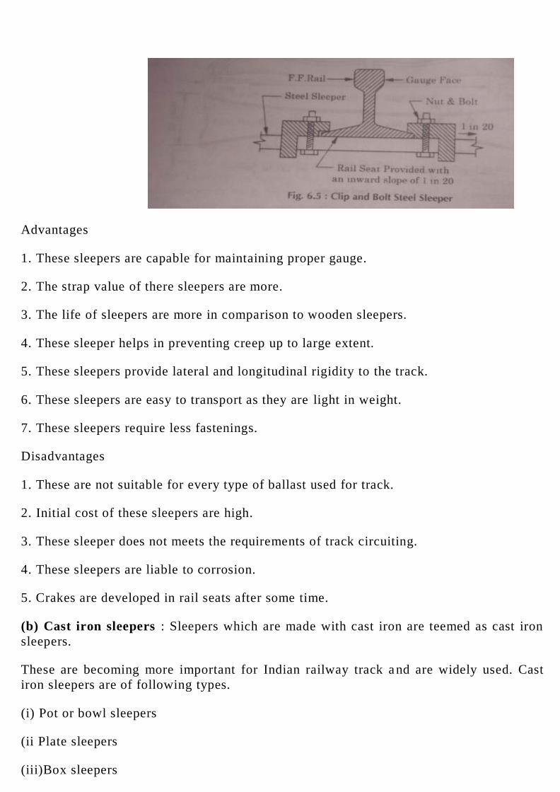
Advantages
1. These sleepers are capable for maintaining proper gauge.
2. The strap value of there sleepers are more.
3. The life of sleepers are more in comparison to wooden sleepers.
4. These sleeper helps in preventing creep up to large extent.
5. These sleepers provide lateral and longitudinal rigidity to the track.
6. These sleepers are easy to transport as they are light in weight.
7. These sleepers require less fastenings.
Disadvantages
1. These are not suitable for every type of ballast used for track.
2. Initial cost of these sleepers are high.
3. These sleeper does not meets the requirements of track circuiting.
4. These sleepers are liable to corrosion.
5. Crakes are developed in rail seats after some time.
(b) Cast iron sleepers : Sleepers which are made with cast iron are teemed as cast iron
sleepers.
These are becoming more important for Indian railway track a nd are widely used. Cast
iron sleepers are of following types.
(i) Pot or bowl sleepers
(ii Plate sleepers
(iii)Box sleepers
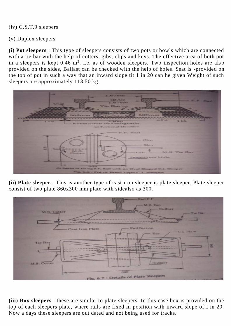
(iv) C.S.T.9 sleepers
(v) Duplex sleepers
(i) Pot sleepers : This type of sleepers consists of two pots or bowls which are connected
with a tie bar with the help of cotters, gibs, clips and keys. The effective area of both pot
in a sleepers is kept 0.46 m2. i.e. as of wooden sleepers. Two inspection holes are als o
provided on the sides, Ballast can be checked with the help of holes. Seat is -provided on
the top of pot in such a way that an inward slope tit 1 in 20 can he given Weight of such
sleepers are approximately 113.50 kg.
(ii) Plate sleeper : This is another type of cast iron sleeper is plate sleeper. Plate sleeper
consist of two plate 860x300 mm plate with sidealso as 300.
(iii) Box sleepers : these are similar to plate sleepers. In this case box is provided on the
top of each sleepers plate, where rails are fixed in position with inward slope of I in 20.
Now a days these sleepers are out dated and not being used for tracks.

(iv) C.S.T 9 sleepers : This is also an other type of cast iron sleepers. these sleepers was
standardized by the central standard track committee. This is most extensively used
sleeper on Indian Railway it consist of
I. A central plate with projected key and a box on the top of the plate.
2. Two inverted triangular pots on either side of the rail seat.
3. Single two way key is provided on the gauge side to hold the rail to the sleeper.
Advantages
1. These sleepers provide firm support to the rail.
2. These provide lateral as well as longitudinal stability to the rails.
3. The bearing area for both the plate is equa ls to 0.46 m2 as in wooden sleeper.
4. Have good scrap value and can re-cast in to sleepers.
Disadvantages
1. The rail seats wears out quickly causing keys to work out loose.
These sleepers are subjected to vibration due to moving loads so it has limited
longitudinal and lateral strength.
3. The suitability of rails is reduced because these provide rigid fastenings.
Due to aforesaid disadvantages these sleepers are improved upon in the form of C.S.T. -
10,11,12 and 13 sleepers.
The CST-9 are extensively used in the Indian Railways is modified to confirm to CST-
13, which has been designed with a view to meet the requirements.
3. Concrete Sleepers
The sleepers which are made of concrete as major constituent are known as concrete
sleepers.

In the early stages wooden sleepers were being used as timber was easily available at that
time. With the development wooden sleepers were replaced with C.1 sleepers, further
advancement in concrete technology, C.I. sleepers were replaced with concrete sleepers.
These sleepers are firstly used and invented by France. In India these were introduced in
1925.
Advantages of concrete sleepers
1. Gauge maintenance proves satisfactory in concrete sleepers.
2. These sleepers found to good for track circuiting.
3. These sleepers have long life.
4. These sleepers are free from fire hazards.
5. These sleepers are durable.
6. These sleepers proves less creep in the track.
7. These sleepers require less number of fitting.
8. Maintenance cost of these sleepers proves very less.
9. There sleepers can withstand against stress induced with high speed traf because of
heavy track modulus.
Disadvantages
1. These sleepers have nil scrap value.
2. The initial cost of concrete sleepers are high.
3. The are difficult to handle and transporting due to their heavy weight.
4. During the derailment there sleeper proves heavy damage.
5. The renewal work of track laid with these sleeper is difficult.
There are two main types of concrete sleeper
1. R.C.C sleeper
2. Pre-stressed concrete sleepers
SLEEPER DENSITY
Sleeper density means the number of sleeper used per rail length on a track. This may
vary on different tracks. The density of sleepers depend upon following factor:
1. Importance of track
2. Speed of train
3. Expected axle load which a track can carry
4. Type of joint provided ,their strength as well as curve of the track.
1. BRIDGE-ENGINEERING
INTRODUCTION
A Bridge is a structure providing passage to cross an obstacles like a stream or a
river or a low ground etc without closing the way beneath. The bridges are made to
provide passage for a railway, a rood, a canal or a pipe line etc
BRIDGE ENGINEERING
It is the art of civil engineering which deals with the construction,
maintenance as well as design of bridges.
Development of Bridges
The development of bridges has great part depending upon the necessity of
the life, easeness of human nature compels the development stages. The
development period of ridge construction is associated with the history of
human civilization. Still the exact period of development of bridges in
different countries of the world con not be predicted, but bridge
development was very fast in some countries where as it is very slow in
under developed countries. It is evident that the idea of developing a
particular type of came to man by many instances of natural behaviour.
There are four major types of bridges
( A) Ar c h Br id ge s
( B) Suspens ion Br idges
( C) Simply Supported Bridges
( D) Truss and Girder Bridges
TECHNICAL TERMS :
Br idge Enginee r ing : The b ranch o f C ivi l Eng inee r ing which
dea ls w ith the des ign, p lanning, cons truc t ion, ma intenance
e tc . o f br idges in known br idge engineer ing.
Culver t : I t is a s ma ll br idge having maximum span o f 6
me t res o r less .
Span : I t i s t he cent re to cent re d is tance be tween two
suppor ts .
Clear Span: I t is t he c lea r d is tance be tween two s uppor ts .
P ie r : I t i s t he int er med ia te s upport o f a b r idge s upe rs t ruc ture .
Abutments : These are end s upport s o f the s upe r -s t ruc ture o f a
br idge .
Approaches : These are cons truc t ion woks which ca r ry the
highway o r ra i lway t rack up to the br idge .
Wing wa l ls : These are the . wa l l s cons t ruc ted on both s ides
o f the abutments to re ta in the ea r then banks and p ro tec t the m
from the wave ac t ion o f wa ter , i f necessa ry.
Founda t ions : Abut ments , w ingwa lls and p ie rs res t on
s t ruc tura l founda t ions which t rans fe r the load from the
s t r ic ture ove r a la rge a rea o f s ub -s o i l be low.
Econo mic s pan : The b r idge leng th is d ivided into number o f
sui tab le spans . The span, fo r which the to ta l cos t o f the
br idge s t ruc ture is min imu m, is ca l led economic span.
Long Span Br idge : I t is a b r idge having length more 120
me t res .
Majo r Br idge : I t is a b r idge having length be tween 30 to
120 met res .
M inor Br idge : I t is a br idge having length more than 6 in.
and less than 30 met res .
Vent W ay : I t i s a culve rt having length less than 1 me tre .
High- leve l or Non-s ub mers ib le Br idge : I t is a br idge , o the r
than a culve rt , which a l lows a l l t he f l ood wate r to pass be low
i t . e •g Al l h ighway o r ra i lways br idges .
Submers ib le or Low leve l Br idge : I t i s a b r idge , which a l lows
nor ma l f lood to pass through i ts vents , but heavy f lood to
pass ove r i t t he reby s ubmerging the communicat ion route .
H. F L. (Highes t Flood Leve l) : I t is t he leve l o f the , h ighes t
f lood eve r recorded o f a r iver OR s trea m.
O• F. L. (Ord ina ry Flood Leve l) : I t i s t he f lood leve l which
gene ra l ly occurs a r ive r OR s t ream eve ry year . .
L. W. L. (Low Wate r Leve l) : I t is t he min imum water leve l
in the d ry wea the r .
Natura l Wa ter -way : I t i s unobs truc ted sec t iona l a rea
ava i lab le a t b r idge s i te fo r f low o f wate r
Wate r-way : The area o f opening which a l lows max. f lood
d ischa rge to pass unde r the b r idge without increas ing the
ve loc ity to a dange rous l imit is ca l led wate rway.
Art i f ic ia l Water -way : I t is a rea o f opening provided unde r
the b r idge s upe r -s t ruc ture through which water f lows .
Af flux (s ee Fig. ) : I t is , r ise in wa ter leve l due to , obs t ruc t ion
by the b r idge in the f low o f wa te r .
Scour : I t i s t he ver t ica l cut t ing o f the dye r bed.
Run-o ff : I t i s t he por t ion o f ra in fa l l on a ca tch ment area ,
which f lows to wa te r course .
Freeboard : The d if fe rence be tween the H. F. L. and the leve l
o f the c rown o f the road a t i ts lowes t po int is c a l led
freeboard.
C lea rance : I t is t he min imum d is tance be tween boundar ies a t
spec if ied pos i t ° o f a b r idg e s t ruc ture .
In case o f road or Ra i lway b r idge it i s t he d is tance ava i lab le
fo r t ra ff ic . The Ve rt ica l c lea rance ' is t he - d is t ance be twee n
the a ff lux and the lowes t po int o f the br idge s upe rs t ruc tu re .
Head-roo m : The d is tance be tween the highes t po int o f a
vehic le and the lowes t po int o f any p rot rud ing me mber o f the
br idge is ca l led headroom.
Foot Br idge : I t i s a b r idge used for car rying pedes t r ians ,
cyc les , anima ls e tc . , only across any obs t ruc t ion o r
dep ress ion.
Cause Way : I t is a "pucca d ip" which a l lows f lood wa ter to
pass ove r i t .
Abut ment P ie r : In b r idges w ith a rches to s upport the
f loo r ing s ome t imes , so me o f the inte rmed ia te s upports a re
made i f s t ronger sec t ion which are ca l led Abut ment P ier .
COMPONENTS OF BRIDGE
Bridge s t ruc ture is co mbinat i on o f two major par ts
(1 ) Sub-s truc ture
(2 ) Super - s t ruc ture
1) s ub-s truc ture : : The lower most pa rt o f b r idge whic h
suppor ts the ent i re s t ruc ture made fro m abut ments , p ie rs e t c ,
inc lud ing s upe rs t ruc ture is c a l led sub - s t ruc ture .
The func t ion o f s ub -s t ruc t ure is s imi lar to tha t o f f oundat ions ,
co lumns and wa l ls e tc o f a bui ld ing. Sub -s t ruc ture s uppor ts
the s upe r-s t ruc ture and d is t r ibute the loads to the so i l t hrough
founda t ion. Subs truc ture o f abr idge cons is ts o f fo l lowing
components .
(1 ) Founda t ions
( i i ) P ie rs
( i i i ) Wing wa l ls
( iv) Abutments
(v) Approaches .
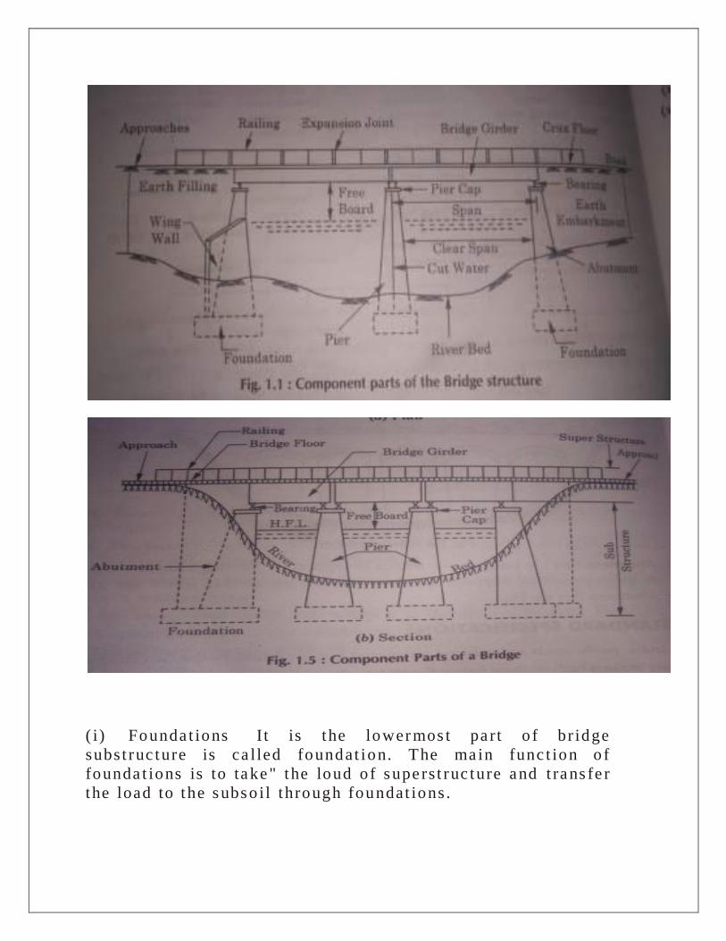
( i ) Founda t ions I t is t he lower mos t pa rt o f br idge
subs t ruc ture is ca l led foundat ion. The ma in func t ion o f
founda t ions is to take" the loud o f s upe rs t ruc ture and t rans fe r
the load to the s ubs o i l t hrough foundat ions .
( i i ) P ie rs : P ie rs a re the int er med ia te s uppor t o f the va r ious
spans o f a b r idge .
P ie rs a re des igned in s uch a way so tha t they can sa fe ly
t rans fe r the load fro m the s upers t ruc ture to the s ub so i l
t hrough founda t ions . P iers a ls o he lps to d iv ide the length o f a
br idge in to s ui tab le numbers o f s pan.
( i i i ) Wing wa l ls : The wa l ls cons t ruc ted on both s ide o f
abet ments to re ta in the e a rth banks o f the r ive r a re ca l led
w ing wa l ls .
Wing wa l ls serves the func t ions to protec t the ea rth banks
aga ins t the ac t ion o f wate r and a l so to re ta in the ear th banks
o f approaches .
( iv) Abutments : The end s upports o f br idge s upe r -s t ruc ture
are known as abut ments . They t rans mit the load fro m b r idge
to the foundat ions and gives f ina l For ma t ion leve l t o the
br idge s upe r s t ruc ture and a ls o re t a in ea rth f i l l ing.
(V) Approaches : Approaches are the po rt ions o f roadway or
ra i lways on both the ends , Which connect the route w ith the
br idge prope r a re te r med as approaches .
The ma in func t ion o f approaches is t o enab le the t ra ff ic to run
ove r road o r ra i lway back.
(2 ) Supe r St ruc ture : I t is t ha t pa rt o f the b r idge ove r which
the t ra f f ic moves sa fe ly. I t cons is ts o f road way. girders ,
a rches e tc ove r which road is s uppor ted. The bas ic func t ion o f
supe r s t r ia t ion is to p rovide car r iage way.
Between Br idge and Culverts
(A) Br idge : I t is a s t ruc ture made to cross obs tac les
provid ing passage ove r an opening without c los ing the same.
The required passage may be fo r road, ra i lway, cana l p ipe l ine
e tc . The to ta l length o f a br idge be tween the faces o f i ts
abut ments is a lways more than 6 m.
The c lasses o f c ross ing
(a) R ive r cross ing
(b ) V ia doct (b r idge ac ross a deep va l ley) ,
(c ) Grade sepa ra t ion.
CULVERT
Culver t is de fine as a s ma l l b r idge cons truc ted ove r a s t rea m
whic h rema in d ry mos t pa rt o f the year . A culve rt is a c ross
dra inage work having a to t a l length not exceed ing 6m betwee n
the face o f abut ment .
Culver t a re provided :
1 . For dr iv ing s ma ll pocke ts and a lso whe re the he ight o f the
bank is s ma ll .
2 . Fo r s ma ll s t r ea ms with r ig id boundary o r semi - r igid
bounda ry.
CLASSIFICATION OF BRIDGES
The bridges are mainly classified according to:
1. According to life- 1. Permanent
2. Temporary
2. According to road level – 1. Deck
2. Through
3. Semi- Through
3. According to material – 1. Timber
2. Masonary
3. Steel
4. R.C.C
5. Prestressed Concrete
4. According to position of high flood level – 1. Submersible
2. Non – Submersible
5. According to Alignment – 1. Strength
2. Skew
6. According to Structural Form —
1. Beam type bridges R.C.C, Tee beam, balanced cantilever, steel girder, plate and
box girder, portal frame bridges, truss .
2. Arch type bridges - open spandrel, filled spandrel, rib type bridges etc.
3. Suspension type - Ramp, trestle and sling bridges.
According to Loading —
1. Class A bridges
2. Class B bridges
3. Class AA bridges
According to Function —
1. Foot bridge
2. Highway
3. Railway
4. Viaduct
5. Aqueduct

According to span:
1. Culvert
2. Minor bridges
3. Major bridges
4. Long span bridges
10. According to Clearance in Navigation Channels — 1. Movable 2. Transporter
11. According to Level of crossing of Highway or Railway — 1. Over-bridges 2.
Under-bridges
The classification of steel bridges may also by done as follows :
(i) Riveted Bridges
(ii) Welded Bridges
(iii) Pin-jointed (or Bolted) Bridges
Permanent & Temporary Bridges
The bridges which are constructed and maintained at low cost and have short span
of life are called Temporary Bridges
Temporary or Low Cost Bridges
These bridges are constructed for short time e.g.
(i) During construction of Darns.
(ii) Permanent bridges.
(iii) In crossing river during Meals.
(iv) During repair work of permanent bridges
(v) During survey work for projects.
(vi) For transporting timber from one bank to another in forests.
These bridges are dismantled when the object of their construction is fulfiled,
hence the name. Permanent or High Cost Bridles
These are bridges which are constructed and maintained at high cost and have long
span of life.
These bridges are built to last for centuries.
Straight & Skew Bridges
The bridge which is at right angles to the axis of water is called straight bridge.
Skew Bridge : The bridge which is constructed at some other angle than 900 to
flow of water is known as skew bridge. It is better, always to avoid a skew bridge
Disadvantages of Skew Bridges
(i) The foundations are likely to be s covered.
(ii) Construction of skew arches is difficult.
(iii) Maintenance is costly and difficult.
(iv) The piers have to resist additional water pressure, as whirls are produced.
Hence special care must be taken that the pie: is parallel to the current. If the
alignment of the central line of a bridge is in a curve, then it has to 'resist additional
forces due to centrifugal action. Therefore alignment must have smooth entry and
exit. On very important routes, where traffic is heavy and temporary bridges are
,unsuitable, permanent bridges are constructed to cross the rivers or streams.
Deck, Through And Semi Through Bridges
The flooring of bridge which carries the traffic may be supported at top, bottom or
at some intermediate level of the superstructure.
When the plateform of a carriage communication route is supported at the top of
the superstructure it is known as deck bridge.

When it is suspended at the bottom of the super structure the bridge is called a
through bridge. If it is supported at some intermediate level, the bridge is a Semi
Through Bridges.
Over and Under Bridges
The bridge constructed to allow a road to pass under is known as Under Bridge.
The bridge constructed to allow a highway to pass route is called an Over Bridge.
Class A, B and AA Bridges
(i) Class A bridges : are bridges which are designed and constructed for 1.R.C.
class A loading.
(ii) Class B bridges : are bridges which are designed and constructed for I.R.C.
class B loading e.g. weight of a lorry.
(iii) Class AA bridges : which are designed and constructed for I. R C. class AA
loading. e.g. tracked vehicles having total. weight 70 Tones, refer Fig. Standard
loading for design of bridges as per I.R.C.
Submersible and Non-Submersible Bridges
(i) Submersible or Low Level Bridge : It is the bridge which allows the highest
flood to pass over its superstructure. These bridges are generally constructed on
unimportant routes and when sufficient funds are not available. In this case storm
water runs only for a short period of the year. The stream remains dry for the rest
period of the year or little quantity of storm water runs under the bridge.
(ii) Non Submersible or High Level Bridge : It is a bridge which does not allow
the high flood water to pass over the floor carrying the communication route.
This type of bridge is of permanent nature. It is constructed on important highways
and to carry an unobstructed traffic throughout the year. Moreover sufficient funds
should be available for its construction.
FACTORS AFFECTING THE SELECTION OF TYPE OF A BRIDGE
The various factors which may affect the selection of type of a bridge are :
1. Nature of the river. 2. Type of bed soil.
3. Volume of traffic. 4. Funds available. 5. Time limit.
6. Foundation conditions.
7. Facilities during construction.
8. Length of the bridge.
9. Economic span of the bridge.
10. Level of H. F. L.
11. Availability of workers. Nature of Traffic.
12. Bearing capacity of bed soil.
13. Materials available.
14. Climatic conditions.
15. Physical features of the site.
16. Width of the bridge. 17. Live loads on the bridge.
2. SITE SELECTION AND COLLECTION OF DATA
SELECTION OF BRIDGE SITE
The selection of site for bridge is done keeping the engineering, economic as well
as soil and geographic aspects of the area. It is not be possible that bridges always
have a wide choice of bridge sites, serially in case of urban area. In order to select
an economical site for bridge construction following are the characteristics for
ideal site :
(i) A straight reach of the river : At bridge silt there should be straight reach of
stream or a river. A straight reach/flow will not tend to change its path thus bridge
can be withstand for a long period/designed period, because it reduces scour near
the bridge.
(ii) Narrow channel with firm banks : Well defined banks of upstream and down
stream provide a safe guard against the river changing its course. River or stream at
bridge site should be as narrow as possible. This leads economy and least possible
length to the bridge thus resulting economy in the initial cost.
(iii) High banks above H.F.L on each side : The site selected for bridge should
have high and stable banks near the bridge thus prevent the overflowing of the
streams during flood, preventing scouring and increasing the life period.
(iv) Foundation : A bridge site should have hard, non erodable bed at short depth
for providing foundation for the bridge. This feature add economy to labour, time,
material for providing piers, abutments etc.
(v) Right Angle crossings : At bridge site the axis of stream should be right angle
to the centre line of the route as far as possible. This provide economy in bridge
construction.
(vi) Obstruction in waterways : Minimum obstructions in waterways provide le
afflux, so while selecting bridge site there should be no or minimum obstruction in
the way.
(vii) Absence of expensive river training works : Site which is to be selected hr
bridge should have free from training works. River training works are very costly
and used for controlling river water so absence of river training works at bridge
site results in economy in initial cost.
(viii) Absence of scouring and silting : Absence of scouring and silting needs less
maintenance cost, so while selecting site for bridge it should be kept in mind that
bridge site should be free from scouring and silting.
(ix) Minimum under water construction : The site which is selected for bridge,
should be such that the minimum construction under water should be needed so
that to avoid under water construction work for the yield of the bridge as well as
economy in the initial
(x) Availability of labour, and material : The site selected for bridge construction
should be carefully selected so that at site there should be easy availability of
labour and material to make the bridge economical in initial cost of construction
and maintenance.
(xi) Absence of sharp curves and approaches : The bridge site should have free
from sharp curves and have straight approaches. Since it is difficult to construct
and maintain the bridges at sharp cruves. So while selecting site for bridge it
should be free form sharp curves.
DATA COLLECTION
Preliminary Data To Be Collected
The engineer in-charge of the investigation for a bridge should collect the
following information :
(i) Name of the river, road and location of the probable bridge sites.
(ii) Present and anticipated future volume and nature of traffic on the road of the
bridge site.
(iii) Location of the nearest Great Trigonometric Survey (G. T. S.) bench mark " its
R. L. (reduced level).
(iv) Soil profile along the probable bridge sites.
(v) Navigational requirements, if any for the river.
(vi) Hydraulic data pertaining to the river This may include ordinary flood level,
highest flood level and low water level. site, shape, slope and nature of the
catchment, frequency and intensity of rainfall in the catchment etc.
(vii) Availability, quality and location of the nearest quarries for stones, for
masonry and for concrete aggregates.
(viii) Nearest place of availability of cement, steel and timber.
(ix) Means of Transport for materials.
(x) Availability of Electric power.
(xi) Availability of skilled and unskilled labour for different trades required for
construction.
(xii) Facilities required for housing labour during construction.
(xiii)Earthquake disturbances of the site.
Preliminary Drawings
The drawings prepared at the time of investigation are -
(i) An index map
(ii) A contour survey plan.
(iii) A site plan.
(iv) A cross section
(v) A longitudinal
(vi) Additional cross-section
(vii) Catchment area map.
(viii) Soil profile
(i) An Index Map : An index map is drawn to a suitable scale (generally 1/50,000).
It should show the proposed location of the bridge, general topography of the area,
existing communications, important towns, existing bridges etc. in the vicinity.
(ii) A contour Survey Plan : It may be drawn to a suitable scale i.e. 1/1000 to
1/5000. Contour plan of the stream showing all topographical features for a
sufficient distance on U/S and D/S of the site must be completed. All sites worth
considering most be shown on the plan.
iii) Site Plan : It may be drawn to a suitable scale (usually 1/500 to 1/11000). This
Should give details of the selected site and details of the stream or river to a of 150
to 200 metres up-stream and down-stream of the selected site.
Details to be indicated on the Site Plan
(a) Name of the stream or river, road and nearest distance marker.
(b) Direction of flow of water.
(c) North direction.
(d) The alignment of existing approaches and proposed crossing with approaches.
(e) Location and reduced level of the bench mark used as datum.
(f) Angle and direction of skew, if the proposed alignment is on a skew.
(g) Name of the nearest village or town at either end of the crossing.
(h) Width of roadway over the bridge.
(i) Location of trial pits and boring holes with their indentification number.
(j) Location of all nallahs, buildings, wells or other obstructions to a road
alignment.
(k) Locations of the longitudinal section and x-sections of road and stream taken
within the area of the plan.
(iv) Cross Section : A cross section of the stream at the proposed bridge site to a
scale about 1/1000 horizontally and about 1/100 vertically.
The x-section should indicate the following information :-
1. Name of the stream, road and chainage.
2. Nature of sub-soil.

3. River bed line with banks up to a level above the highest flood level.
4. Formation level.
5. Depth of cutting or filling on the approaches.
6. Low water level, normal flood level and the highest flood level.
(v) Longitudinal Section : Suitable scale may be used for horizontal distance but
vertical scale must not be less than 1/1000, L-Section of the stream showing site of
the. bridge with the L. W. L., 0. F. L. and bed levels at suitable intervals along tile-
- approximate centre line of the deep water channel should be drawn.
(vi) Additional Cross-Sections : These may, be drawn of the stream or river,
suitable distance both U/S and D/S of the proposed bridge site.
(vii) Catchment area Map : It is prepared for the stream or river at the proposed, of
bridge by tracing the line of the ridge of the watershed from the topographical of
survey of India drawn to a scale 1/50,000.
(viii) Soil Profile : The soil profile must show the bed and banks, of levels of layer
and classification of the sub soil. It should be found along bridge alignments by
sub soil exploration.

SCOUR
cutting of bed or deepening of river due to action of water is called scouring. More
over horizontal widening of river is called 'Erosion.
Scour 0f stream bed occurs during the passage of a flood discharge. Firstly
scouring will be at the nose of the piers and at bends, then it will start in the
foundation. Due to reduction in bearing capacity piers will sink down, hence
causing the failure of the bridge.
Maximum and Normal Depth of Scour
In India, Lacey's equation is commonly uscd for finding normal depth of scour for
natural streams in alluvial beds.
if d = normal depth of scour below H. F. L. in rn.
Q = discharge in m3/sec. f= Lacey's silt factor Then d = 0.473 (Q/f)0.33
Maximum Depth of Scour (d) : May be taken as follows:-
(i) for straight reach = 1.27d
(ii) for moderate bend = 1.50d
(iii) At a severe bend = 1.75d
(iv) For a right angled bend = 2.00d
(v) For noses of piers = 2.0d
(vi) For U/S noses of guide banks = 2.75d
Prevention of Scouring The measures taken are as under
(i) Shape of piers should be such that it may not cause currents, eddies water.
(ii) The bridge site must have stream line flow.
(iii) Pitching of heavy stones must be done on U/S and D/S of the bridge
(iv) Bed particles of the bridge should be such that these may stand the high
velocity of water.
(v) Sufficient water way should be provided under the bridge, so that velocity of
water must not exceed the limit alter which scouring starts.
(vi) Sheet- piling may be done to prevent scouring in sandy beds.
(vii) Piles should be driven in the stream or river bed to avoid scouring.
RUN OFF
It is the portion of rain-fall on a catchment area which flow to the water course
depends on the following factors
(i) Duration of rain-fall.
(ii) Intensity of rain-fall.
(iii) Area and type of catchment area.
(iv) Slope of catchment area.
(v) Shape of catchment area.
(vi) Initial state of catchment area regarding wetness.
(vii) Type of soil in catchment area i.e. porosity etc.
Calculation of Run-Off
The following are the usually used empirical formulae for calculating the rum If Q
it., discharge in cum/ sec.
C = constant, value depends upon nature of catchment area
A area of catchment in sq.-km.
then (i) According to Dicken's formula
Q= CA3/4
According to Ryve’s tormula
Q= CA2/3
Economical Span
The span for which the total cost of the bridge will be minimum is called economic
span of the bridge.
The most economical span length is that for which the cost of superstructure...( of
substructure. This condition may be found as under :-
Let L = total linear water-way.
I = length of one span.
n = No. of spans = L/l
A = Cost of approaches.
B = Cost of two abutments, including foundations.
Z = Cost of one pier, including foundations.
C = total cost of bridge.
Assume that cost of superstructure of one span is proportional to square of the s,
length.
(1) Then total cost of superstructure = n k 12 where k is a constant.
(ii) Cost of flooring, railing etc. is proportional to the total length of bridge' may be
taken as K'L.
For minimum cost dC/dl= 0
By differentiating, putting n = L/l and equaling result = 0
we have : Z=k12
Hence for economic span, the cost of superstructure of one span= cost of
substructure of the same span. I.R.C. recommendations for small culverts and
bridges are :-
(i) For R. C. C. slab bridge—economic span= 1.5 H where H Heigh above the
foundation.
(ii) For Masonry Arch Bridge — Economic span = 2H, where H = height of pier
above foundation up to springing line.
Length of Bridge
After calculating the economic span length, water way, the length of bridge is
found. More over piers are designed and their sizes are noted.
Then Length of Bridge =Water way + width of all piers.
Width of Carriage Way
The minimum width of carriage way for one lane is 3.8 m. For every additional
lane, a minimum of 3.0 m must be allowed.
The width of carriage way will depend on the volume and intensity of traffic
anticipated to use. the bridge. In urban areas it is desired to provide separate cycle
tracks, foot paths etc. Bridges should have carriage way of two, four or multiples
of two lanes.
As per I. R. C. (Indian Road Congress) recommendations it is required to provide a
carriage way of 7.5 metres instead of 6.8 m for two lane traffic.
Bridge Alignment
The location of centre line of a communication route to be carried by the bridge at
the selected site is called bridge alignment.
While locating the alignment of a bridge following points to be considered
(i) The alignment for bridge is free from curves because it cause difficulty in
construction as well as maintenance of a curved bridges. Curved alignment of
bridges are also liable to traffic accidents.
(ii) The center line of the bridge should always be at right angle to the axis of river.
This type of bridges are easy in construction and moreover helps in economic
constructions.
(iii) The most important point while making bridge alignment is that it should be
avoided from skew bridge because skew bridge are difficult in construction also
obstruct the water way.
FOUNDATION
INTRODUCTION
Foundation is the lower-most part of the sub-structure. It transfer load from the
super-structure of a bridge. Piers and abutments are provided with foundations. All
the loads that came on the bridges, the forces are to be transmitted to the
foundations. Excessive settlements or shear failure of the foundations damage the
bridge. The depth of foundations should be such that they shall be located below
the depth of maximum scour so that these are not damaged.
BRIDGE FOUNDATION
The lowermost parts i.e. piers, abutments etc. which supports the bridge and helps
transferring loads safety to the sub-soil are termed as bridge foundation.
Function of Foundation
Foundations serve the following purposes :
(I) Transmit the loads from the superstructure and substructure over a bearing area
in such a way that keep the maximum stress within the permissible bearing
capacity of the soil.
(ii) Prevent of tilting and overturning of piers and abutment,
(iii) Stabilization of the supporting material of the river bed in order to prevent
sinking of the pier
(iv) Provide of a level base for the construction of substructure above the
foundation.
(v) Prevention of settlement of the structure by transmission of the load to the
bearing strata uniformly.
(vi) It prevents heaving up of the soil under applied load.
(vii) It provide stability to the structure/bridge.
Requirement of a Foundation
There are the three basic requirements of a foundation,

1. Location
2. Stability
3. Settlement
1. Location : The location of foundation structure should be so that it is able to
resist influences which may adversely affect its performance. This aspect requires
careful judgment of an engineer.
2. Stability : The foundation structure should be stable or safe against any possible
failure.
3. Settlement The foundation should not settle to such an extent so as to impair its
usefulness. It is however, difficult to define the amount of settlement. It is seen that
the differential settlement cause damage to the structure. So it should be avoided.
The term differential settlement is used to indicate the non-uniform settlements of
different points of the same foundation or of two independent foundations. It is
mainly due to prevailing foundation bed conditions at site.
BRIDGE FOUNDATION CLASSIFICATIONS
Bridge foundations are classified in three major categories.
1. Land foundations ;
2. Foundations constructed on soil having wager at shallow depths ;
3. Under water foundations.
1. Land Foundations : The foundations constructed on a dry land are known as land
foundations.
Land foundations can be easily constructed because they are mostly shallow and
do not require any special provision for their construction.
Land foundations are further classified as :
(a) Spread or open foundations ;
(b) Raft foundatlions ;
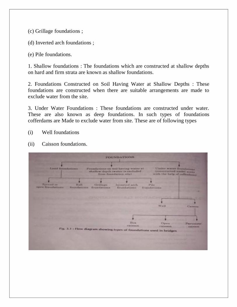
(c) Grillage foundations ;
(d) Inverted arch foundations ;
(e) Pile foundations.
1. Shallow foundations : The foundations which are constructed at shallow depths
on hard and firm strata are known as shallow foundations.
2. Foundations Constructed on Soil Having Water at Shallow Depths : These
foundations are constructed when there are suitable arrangements are made to
exclude water from the site.
3. Under Water Foundations : These foundations are constructed under water.
These are also known as deep foundations. In such types of foundations
cofferdams are Made to exclude water from site. These are of following types
(i) Well foundations
(ii) Caisson foundations.
GRIP LENGTH
Unless the foundations are rested on rock, proper grip length below the maximum
scour level must be provided. As per I.R.C., the minimum req uired grip length is
recommended as one-third the maximum scour depth for road bridges and one-half
of maximum scour depth for railway bridges. The advantage of grip length is to
ensure stability under heavy flood conditions.
Factors Affecting Depth of Foundation
(As per I.R.C.) :According to I.R.C. Bridge Code the factors affecting depth of
foundation are as under :
(i) The minimum depth of foundation below H. F. L. must be 1.33 D, where : D =
anticipated max. depth of scour below H. F. L.
(ii)The foundation must be taken below the scour level and to the level at which
there is little variation in the water content of the subsoil.
(iii) The forces due to wind and seismic forces when considered, the intensity of
load must not exceed the safe bearing capacity of the subsoil by more than 25%.
(iv) In well foundations, the effect of skin friction should be considered on the
portions below the maximum depth of scour.
Skin friction is the frictional resistance of the surrounding soil on the outer surface
of steining of wells or well caissons.
(v) For deciding the depth of well foundation grip length must he considered as per
I.R.C. recommendations.
Rankin's Formula For Calculating Minimum Depth of Foundation
If p = safe bearing capacity of the subsoil in tonnes/m2
w = specific weight of the subsoil in tonnes/ m3
Q= Angle of repose or friction of subsoil in degrees.
Then minimum depth of foundation =h=p/w(1-sinQ/1+sinQ)2

Factors which influence Bridge Foundation
Following three factors influence the design of bridge foundations :
1. Bearing capacity of soil
2. Frictional resistance
3. Scour.
1. Bearing capacity of soil : The bridge foundations should be kept to such a depth
that the soil at that depth has sufficient safe bearing capacity to withstand the load
without any settlement. If W is the total load on bridge foundation and A is the
area of bridge foundation, the W/A should be less than or equal to the safe bearing
capacity of soil.
2. Frictional resistance : Some foundations resist the load coming upon them by the
friction offered by the surrounding soil. in such cases, the bridge foundations
should be taken upto suitable depth so that enough frictional resistance is
developed to resist the load coming on the bridge foundations.
3.Scour : -The term scour is used to indicate the increase in depth in vertical
direction of the bed of river. Such increase in depth mainly occurs due to the
currents of flowing water, bed material, alignment of river, flood discharge, bed
slope, direction of flow, shape of pier, etc. The scouring action of the current is not
uniform all along the bed width. It is not so even in straight reaches. There is
deeper scour than normal at the piers or other obstructions and also at bends.
Hence, it is necessary to determine the maximum scour depth and the bridge
foundations should be taken beyond this maximum depth of scour. The term scour
should not be confused with erosion which indicates the horizontal widening of
river.
Factors Affecting the Selection of Bridge Foundation
The following are the factors which effect the selection of foundation :
(i) Type of soil.
(ii) Nature of. soil.
(iii) Type of the bridge.
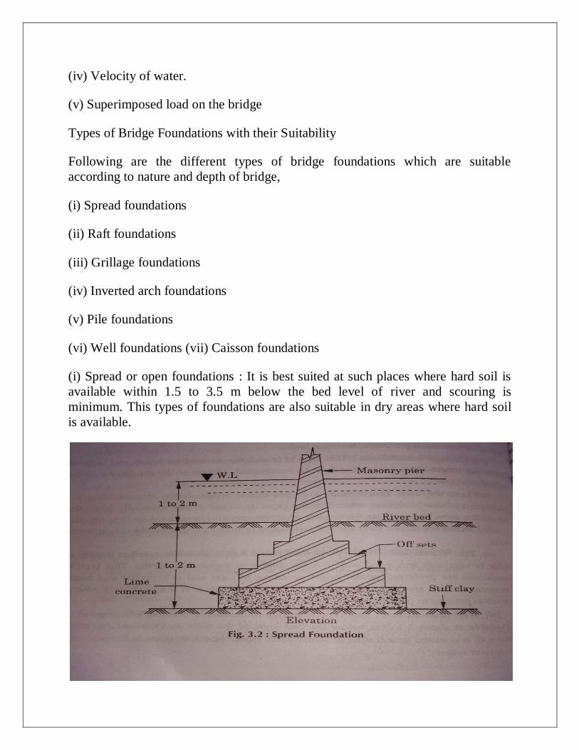
(iv) Velocity of water.
(v) Superimposed load on the bridge
Types of Bridge Foundations with their Suitability
Following are the different types of bridge foundations which are suitable
according to nature and depth of bridge,
(i) Spread foundations
(ii) Raft foundations
(iii) Grillage foundations
(iv) Inverted arch foundations
(v) Pile foundations
(vi) Well foundations (vii) Caisson foundations
(i) Spread or open foundations : It is best suited at such places where hard soil is
available within 1.5 to 3.5 m below the bed level of river and scouring is
minimum. This types of foundations are also suitable in dry areas where hard soil
is available.
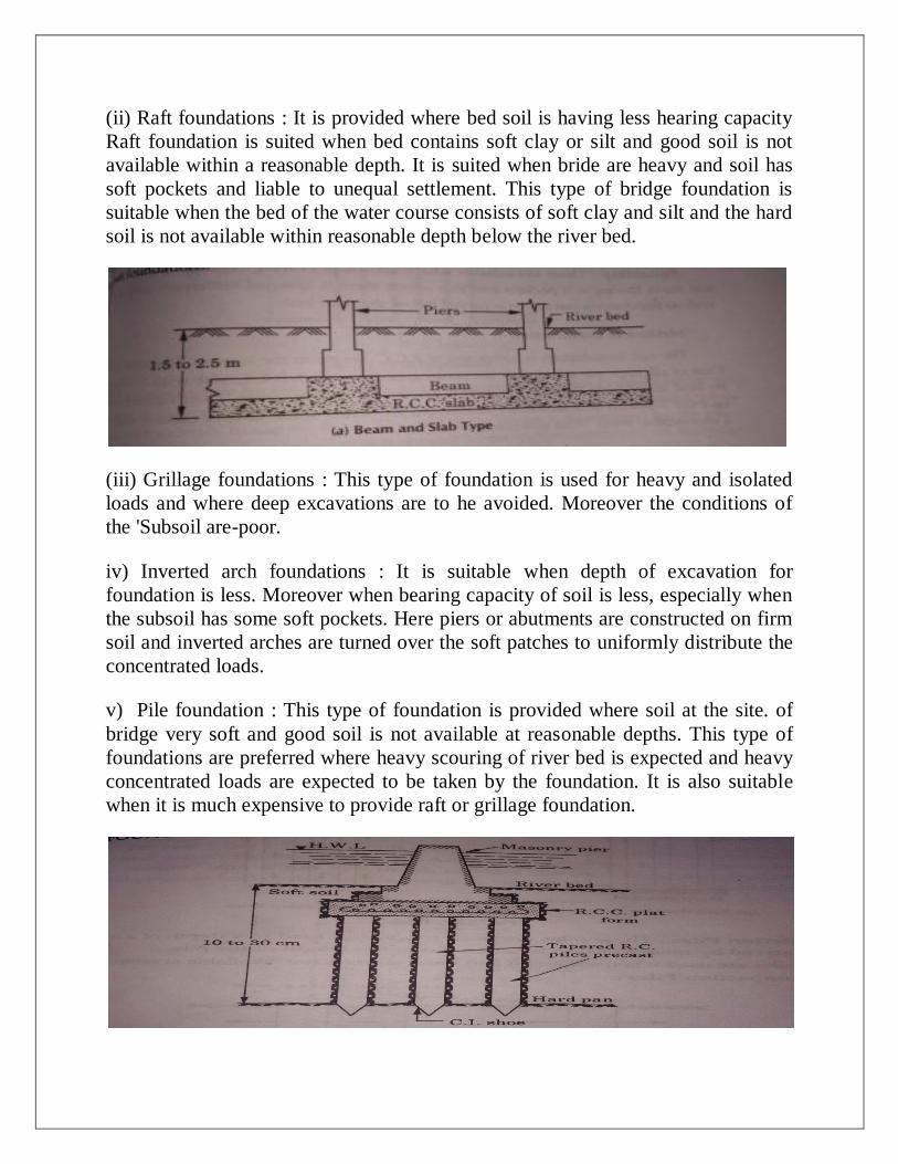
(ii) Raft foundations : It is provided where bed soil is having less hearing capacity
Raft foundation is suited when bed contains soft clay or silt and good soil is not
available within a reasonable depth. It is suited when bride are heavy and soil has
soft pockets and liable to unequal settlement. This type of bridge foundation is
suitable when the bed of the water course consists of soft clay and silt and the hard
soil is not available within reasonable depth below the river bed.
(iii) Grillage foundations : This type of foundation is used for heavy and isolated
loads and where deep excavations are to he avoided. Moreover the conditions of
the 'Subsoil are-poor.
iv) Inverted arch foundations : It is suitable when depth of excavation for
foundation is less. Moreover when bearing capacity of soil is less, especially when
the subsoil has some soft pockets. Here piers or abutments are constructed on firm
soil and inverted arches are turned over the soft patches to uniformly distribute the
concentrated loads.
v) Pile foundation : This type of foundation is provided where soil at the site. of
bridge very soft and good soil is not available at reasonable depths. This type of
foundations are preferred where heavy scouring of river bed is expected and heavy
concentrated loads are expected to be taken by the foundation. It is also suitable
when it is much expensive to provide raft or grillage foundation.
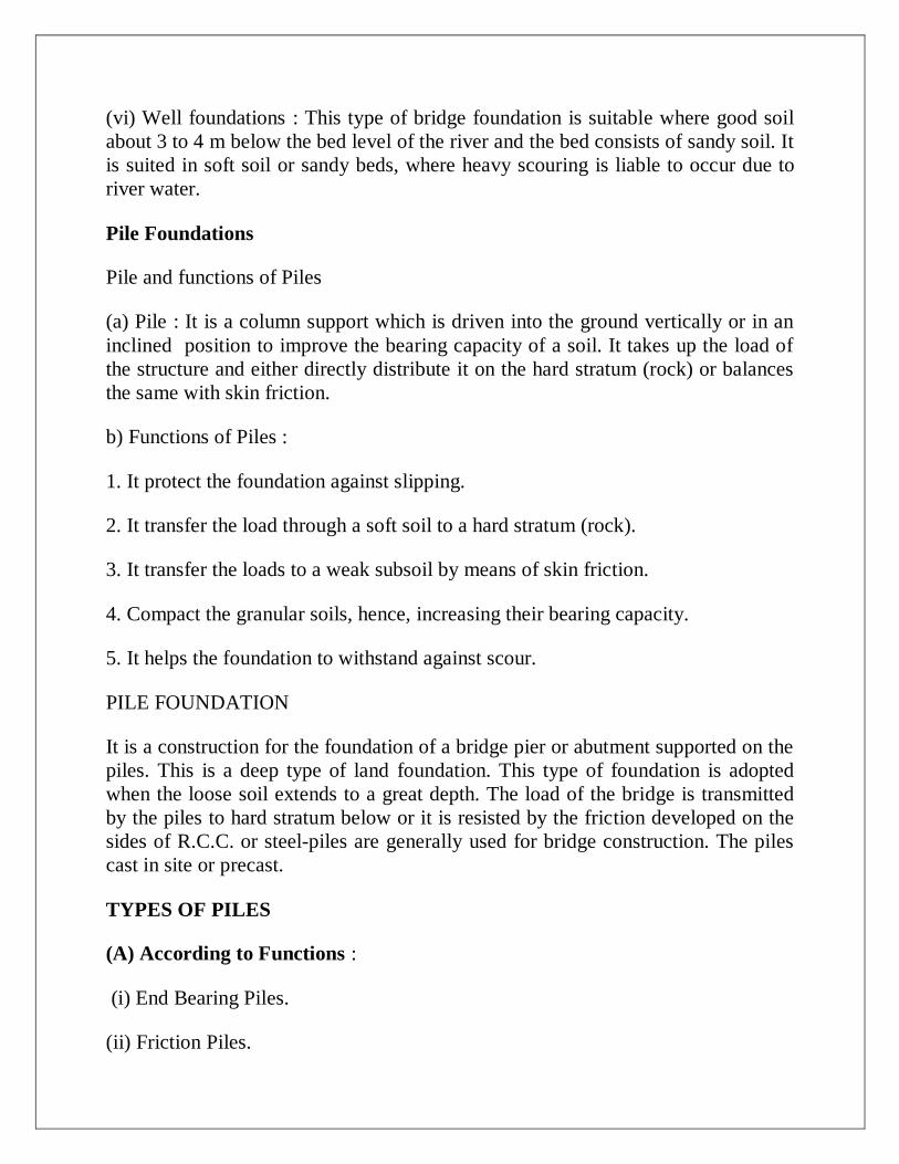
(vi) Well foundations : This type of bridge foundation is suitable where good soil
about 3 to 4 m below the bed level of the river and the bed consists of sandy soil. It
is suited in soft soil or sandy beds, where heavy scouring is liable to occur due to
river water.
Pile Foundations
Pile and functions of Piles
(a) Pile : It is a column support which is driven into the ground vertically or in an
inclined position to improve the bearing capacity of a soil. It takes up the load of
the structure and either directly distribute it on the hard stratum (rock) or balances
the same with skin friction.
b) Functions of Piles :
1. It protect the foundation against slipping.
2. It transfer the load through a soft soil to a hard stratum (rock).
3. It transfer the loads to a weak subsoil by means of skin friction.
4. Compact the granular soils, hence, increasing their bearing capacity.
5. It helps the foundation to withstand against scour.
PILE FOUNDATION
It is a construction for the foundation of a bridge pier or abutment supported on the
piles. This is a deep type of land foundation. This type of foundation is adopted
when the loose soil extends to a great depth. The load of the bridge is transmitted
by the piles to hard stratum below or it is resisted by the friction developed on the
sides of R.C.C. or steel-piles are generally used for bridge construction. The piles
cast in site or precast.
TYPES OF PILES
(A) According to Functions :
(i) End Bearing Piles.
(ii) Friction Piles.
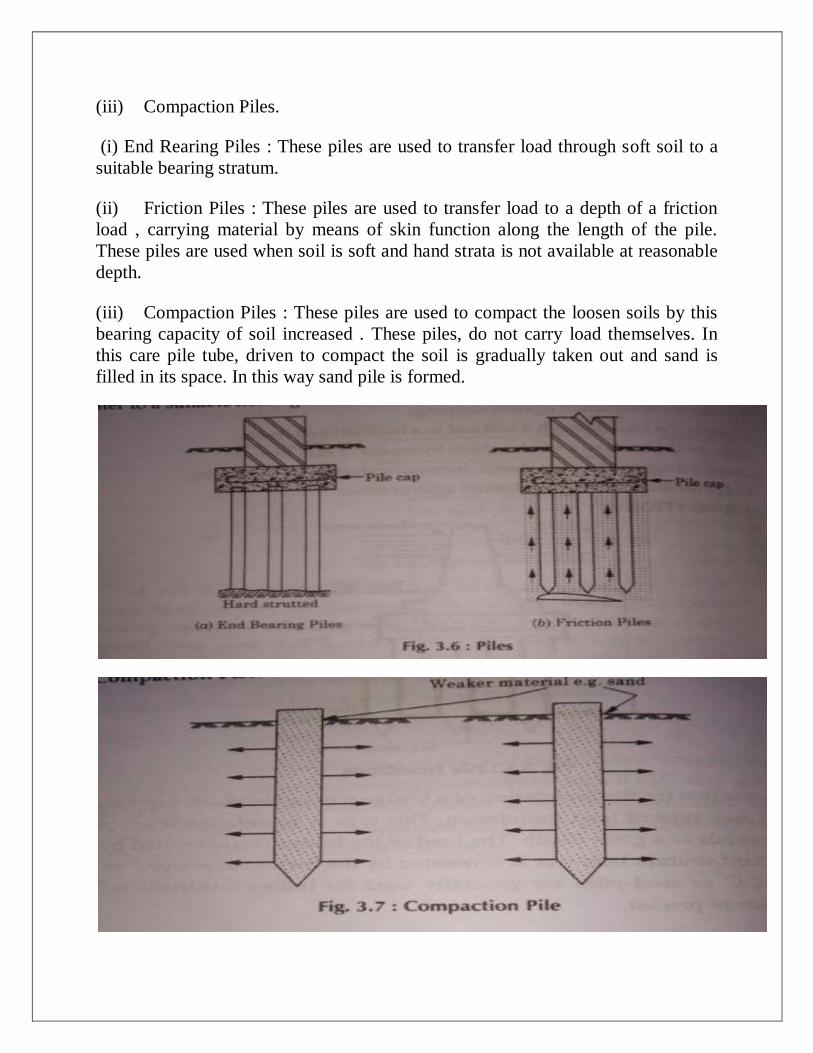
(iii) Compaction Piles.
(i) End Rearing Piles : These piles are used to transfer load through soft soil to a
suitable bearing stratum.
(ii) Friction Piles : These piles are used to transfer load to a depth of a friction
load , carrying material by means of skin function along the length of the pile.
These piles are used when soil is soft and hand strata is not available at reasonable
depth.
(iii) Compaction Piles : These piles are used to compact the loosen soils by this
bearing capacity of soil increased . These piles, do not carry load themselves. In
this care pile tube, driven to compact the soil is gradually taken out and sand is
filled in its space. In this way sand pile is formed.
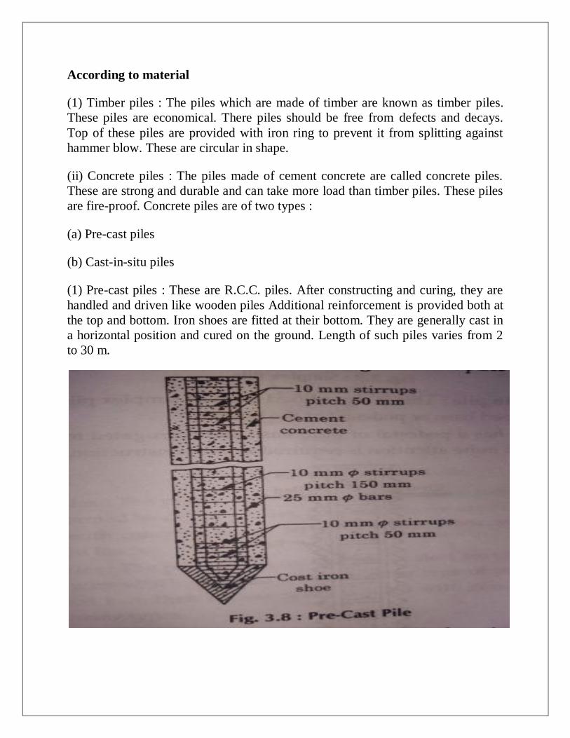
According to material
(1) Timber piles : The piles which are made of timber are known as timber piles.
These piles are economical. There piles should be free from defects and decays.
Top of these piles are provided with iron ring to prevent it from splitting against
hammer blow. These are circular in shape.
(ii) Concrete piles : The piles made of cement concrete are called concrete piles.
These are strong and durable and can take more load than timber piles. These piles
are fire-proof. Concrete piles are of two types :
(a) Pre-cast piles
(b) Cast-in-situ piles
(1) Pre-cast piles : These are R.C.C. piles. After constructing and curing, they are
handled and driven like wooden piles Additional reinforcement is provided both at
the top and bottom. Iron shoes are fitted at their bottom. They are generally cast in
a horizontal position and cured on the ground. Length of such piles varies from 2
to 30 m.
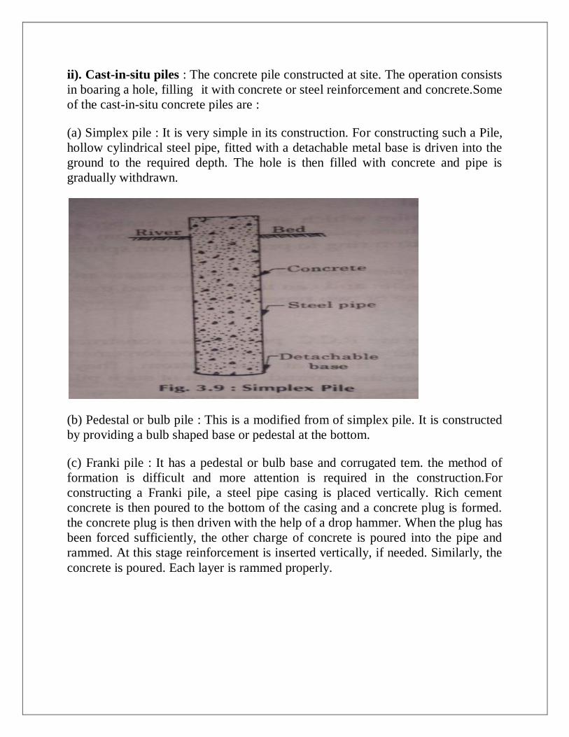
ii). Cast-in-situ piles : The concrete pile constructed at site. The operation consists
in boaring a hole, filling it with concrete or steel reinforcement and concrete.Some
of the cast-in-situ concrete piles are :
(a) Simplex pile : It is very simple in its construction. For constructing such a Pile,
hollow cylindrical steel pipe, fitted with a detachable metal base is driven into the
ground to the required depth. The hole is then filled with concrete and pipe is
gradually withdrawn.
(b) Pedestal or bulb pile : This is a modified from of simplex pile. It is constructed
by providing a bulb shaped base or pedestal at the bottom.
(c) Franki pile : It has a pedestal or bulb base and corrugated tem. the method of
formation is difficult and more attention is required in the construction.For
constructing a Franki pile, a steel pipe casing is placed vertically. Rich cement
concrete is then poured to the bottom of the casing and a concrete plug is formed.
the concrete plug is then driven with the help of a drop hammer. When the plug has
been forced sufficiently, the other charge of concrete is poured into the pipe and
rammed. At this stage reinforcement is inserted vertically, if needed. Similarly, the
concrete is poured. Each layer is rammed properly.
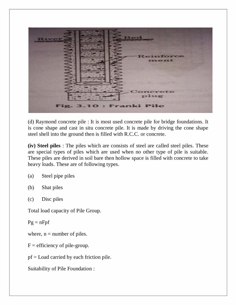
(d) Raymond concrete pile : It is most used concrete pile for bridge foundations. It
is cone shape and cast in situ concrete pile. It is made by driving the cone shape
steel shell into the ground then is filled with R.C.C. or concrete.
(iv) Steel piles : The piles which are consists of steel are called steel piles. These
are special types of piles which are used when no other type of pile is suitable.
These piles are derived in soil bare then hollow space is filled with concrete to take
heavy loads. These are of following types.
(a) Steel pipe piles
(b) Shat piles
(c) Disc piles
Total load capacity of Pile Group.
Pg = nFpf
where, n = number of piles.
F = efficiency of pile-group.
pf = Load carried by each friction pile.
Suitability of Pile Foundation :

(i) When soil is very soft to a considerable depth.
(ii) Heavy concentrated loads are coming on the structures.
(iii) Raft or Grillage foundation either not possible to construct or uneconomical
(iv) When buildings are constructed on a sloping ground under lying a laver of
clayey soil to safeguard slipping.
(v) Structures on sea shore to avoid scouring.
Determination of Allowable Load on a Pile
It is difficult to find the bearing capacity of a pile driven into the ground and it is
generally estimated by employing the empirical formulae based on long experience
or by carrying out load tests. The "Engineering News Formula" is simple and used
very widely. It was proposed by A.M. Wellington (1888) in the following general
form :
Pa= WH / F(S + C)
where P. = allowable load
W = weight of hammer
H = height of fall of the hammer
S = average penetration in cm/blow for the last 5-10 blows for gravity hammer and
the last 10-20 blows for others.
C = empirical constant
F = Factor of safety = 6.
If we denote W in kg. S in cm,
H is on there,
C = 2.5 cm for drop hammer.
C = 0.25 cm for single and double acting hammer
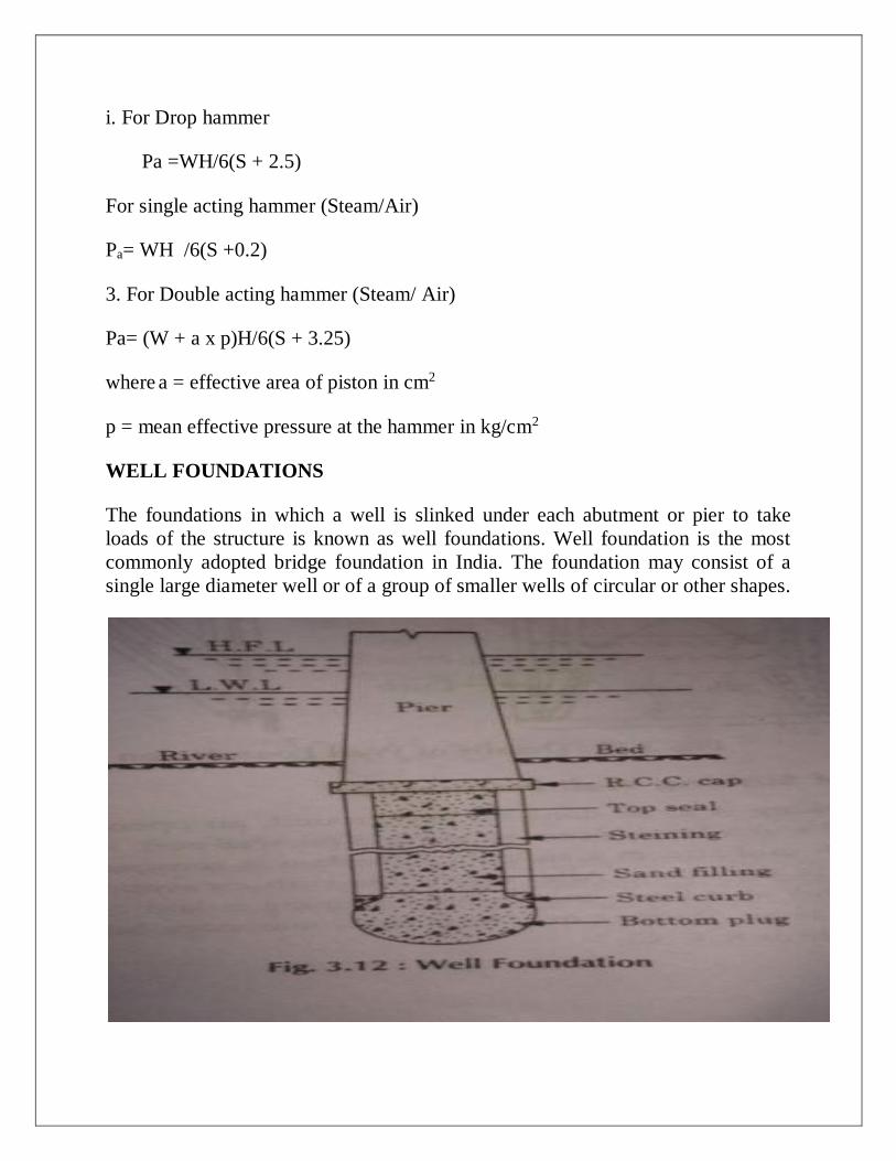
i. For Drop hammer
Pa =WH/6(S + 2.5)
For single acting hammer (Steam/Air)
Pa= WH /6(S +0.2)
3. For Double acting hammer (Steam/ Air)
Pa= (W + a x p)H/6(S + 3.25)
where a = effective area of piston in cm2
p = mean effective pressure at the hammer in kg/cm2
WELL FOUNDATIONS
The foundations in which a well is slinked under each abutment or pier to take
loads of the structure is known as well foundations. Well foundation is the most
commonly adopted bridge foundation in India. The foundation may consist of a
single large diameter well or of a group of smaller wells of circular or other shapes.
Types of Well Foundations
1. Deep wells foundations
2. Shallow wells foundations •
1. Deep wells foundations : The foundations in which wells are sunk deeper than,
the maximum possible depth of scour are called deep well foundations. This
system of known Punjab system, since this type of foundations is most commonly
employed under bridge piers in Northern India, particularly in Punjab.
Advantages : of well foundations is that, No need of bed floors and curtain walls
for their protection thus economical in maintenance.
These foundations do not interfere with the natural flow of water thus they will not
result afflux and scour and maintain stability of the foundations. It has
disadvantages like these foundations are difficult to construct.
Deep well foundations are useful for alluvial rivers in pain country, having heal)
discharge and are liable to scour.
2. Shallow well foundations : The foundations in which wells are not sunk deeper
than the maximum possible depth of scour are called shallow well foundations.
This system of foundations is known as Madras system, since this type of well
foundation is most commonly employed under bridge piers in South India,
particularly in Madras.
Main advantages of Shallow foundations are that shallow well foundations are easy
in construction. These foundations are cheaper due to shallow depth.
Disadvantages of Shallow foundations are :
Shallow well foundations require additional floors and curtain walls for their
protection against scour and are difficult to maintain.
These foundations interfere with the natural flow of water and thus they will cause
afflux and scour.
Component Part of a Well Foundation and Their Functions
The different component parts of a well foundation and their functions
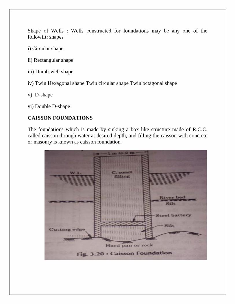
Shape of Wells : Wells constructed for foundations may be any one of the
followift: shapes
i) Circular shape
ii) Rectangular shape
iii) Dumb-well shape
iv) Twin Hexagonal shape Twin circular shape Twin octagonal shape
v) D-shape
vi) Double D-shape
CAISSON FOUNDATIONS
The foundations which is made by sinking a box like structure made of R.C.C.
called caisson through water at desired depth, and filling the caisson with concrete
or masonry is known as caisson foundation.

Types of Caisson : `These are as under :
(i) Box caissons.
(ii) Open or Dredging caissons.
(iii) Pneumatic caissons.
(1) Box Caissons : These are strong water tight vessels open at top and close at
bottom. Box caissons are generally made of timber masonry or concrete, and are
used where little excavation is required. To place the caisson in position, it is
launched and floated to pier site where it is sunk in position. Then it is filled with
concrete or masonry to serve as foundation for a structure like bridge pier. This
type of caisson is suitable for constructing bridge foundations under water, when
the depth of water is considerable but a firm ground or rocky base is available
immediately below the river bed. In its case, little excavation is required for
preparing the site to provide and uniform bearing to the caisson.
(ii) Open or Dredging Caissons : This type of caisson is open both at the top and at
the bottom. Open caissons are generally made of steel, masonary or concrete and a;
sunk like masonary wells. They form the most common type of deep foundations
bridges in India.
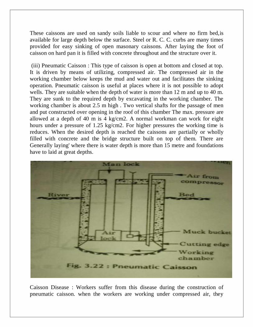
These caissons are used on sandy soils liable to scour and where no firm bed,is
available for large depth below the surface. Steel or R. C. C. curbs are many times
provided for easy sinking of open masonary caissons. After laying the foot of
caisson on hard pan it is filled with concrete throughout and the structure over it.
(iii) Pneumatic Caisson : This type of caisson is open at bottom and closed at top.
It is driven by means of utilizing, compressed air. The compressed air in the
working chamber below keeps the mud and water out and facilitates the sinking
operation. Pneumatic caisson is useful at places where it is not possible to adopt
wells. They are suitable when the depth of water is more than 12 m and up to 40 m.
They are sunk to the required depth by excavating in the working chamber. The
working chamber is about 2.5 m high . Two vertical shafts for the passage of men
and put constructed over opening in the roof of this chamber The max. pressure are
allowed at a depth of 40 m is 4 kg/cm2. A normal workman can work for eight
hours under a pressure of 1.25 kg/cm2. For higher pressures the working time is
reduces. When the desired depth is reached the caissons are partially or wholly
filled with concrete and the bridge structure built on top of them. There are
Generally laying' where there is water depth is more than 15 metre and foundations
have to laid at great depths.
Caisson Disease : Workers suffer from this disease during the construction of
pneumatic caisson. when the workers are working under compressed air, they

suffer from this disease when they return to atmospheric pressure. When workers
are subjected to compressed air, nitrogen is absorbed along with oxygen by the
tissue fluid of the man. The 02 is dissolved in blood while nitrogen is kept in
suspension because it is not soluble in blood. The main symptoms of this disease
are headache, dizziness pain in legs, trouble in speaking etc. This may results in
paralysis, loss of consciousness or even fatal accidents.
Precautions to avoid caisson disease :
(1) Main locks should be well ventilated.
(ii) Rate of compression and decompression must be properly controlled.
(iii) Workers with strong hearts may be employed.
(iv) Temperature of working chamber should be kept at 25°C.
(v) A medical chamber or dispensary should be provided near the work site.
(vi) Every worker should work for one shift in a day.
(vii) A stand by air compressing plant should be kept ready for emergency.
(viii) Good circulation must be provided at the work.
BRIDGE
COFFER DAMS
Cofferdams are made to construct the foundations, abutments or piers under water
i.e. to make constructions under water. These are temporary structure which are
removed from the site after the constructional work is completed.
A temporary structure constructed to prevent the water to enter an area where
permanent structure is to be built up are known as cofferdams".
These are generally required for projects like dams, docks etc. The selection of the
cofferdam to be made at site of construction mainly depends upon bed of upriver,
type of soil etc.
Requirements of a Cofferdam
(i) It should be easy in construction.
(ii) It must be water tight.
(iii) The design. must be such that total cost of construction and maintenance
should be minimum.
(iv) Cofferdam should be sufficiently stable against overturning, sliding and
bursting under floods.
(v) As far as possible it should occupy less area.
(vi) It should provide least obstruction to the flow of water.
(vii) Its height must be sufficiently higher than highest flood level in the river.
(viii) It should be so planned as to facilitate easy dismantelling and reuse of
materials.
Factors Affecting Selection of a Type of Cofferdam
(i) Depth of water to be dealt with.
(ii) velocity of flowing water.
(iii) Extent of an area to be protected by a cofferdam.
(iv) Type of construction material available near site of work.
(v) Skilled labour available at site of work.
(vi) Transportation facilities available.
(vii) Nature of the river bed on which the cofferdam is to rest.
(viii) The possibility of overtopping by tides or floods.
(ix) The possibility of scour due to reduction of water-way caused by the
construction of cofferdam.
Types of Cofferdams
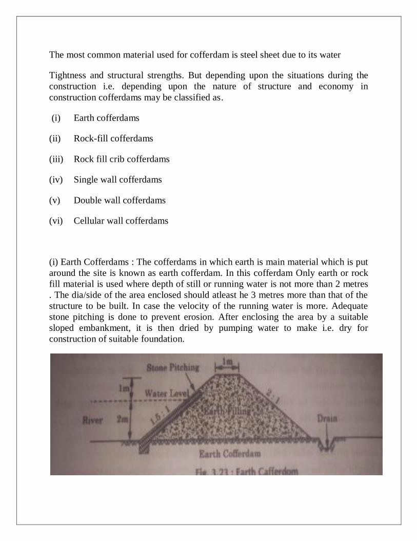
The most common material used for cofferdam is steel sheet due to its water
Tightness and structural strengths. But depending upon the situations during the
construction i.e. depending upon the nature of structure and economy in
construction cofferdams may be classified as .
(i) Earth cofferdams
(ii) Rock-fill cofferdams
(iii) Rock fill crib cofferdams
(iv) Single wall cofferdams
(v) Double wall cofferdams
(vi) Cellular wall cofferdams
(i) Earth Cofferdams : The cofferdams in which earth is main material which is put
around the site is known as earth cofferdam. In this cofferdam Only earth or rock
fill material is used where depth of still or running water is not more than 2 metres
. The dia/side of the area enclosed should atleast he 3 metres more than that of the
structure to be built. In case the velocity of the running water is more. Adequate
stone pitching is done to prevent erosion. After enclosing the area by a suitable
sloped embankment, it is then dried by pumping water to make i.e. dry for
construction of suitable foundation.

(ii) Rock Filled Dams : The cofferdams which are made of broken stone at the site
in the shape of embankment along the streams are known as rock-filled dams
These dams are similar to earth dams but having steeper slopes up to 1 in 1.25
These dams are made impervious in nature by placing impervious layer of earth on
the outer face of the cofferdam.
These type of cofferdams are cheap. and easy to construct. These dams has
isadvantage that it cannot be made water tight as the junctions between rock and
ver bed is always susceptible to leakage and it is difficult to locate the seepage and
hence dewatering become costly.
Rock : This type of cofferdam is generally constructed at the site, where Efficient
rock is easily and cheaply available.
Rock-fill cofferdam can withstand the overtopping of water without any serious
mage. These are suitable for depths of water up to 3 m and even in the case of
swift water.
(iii) Rock-fill crib cofferdams : The type of cofferdam in which cribs are filled
With rock or gravel or earth at the site according to availability are known as
rockfill crib cofferdams.
Cribs is a framework of horizontal and cross beams made of timber laid in
alternate layers is called crib. In this type of cofferdam, the crib base is prepared on
the shore and then floated to the position and is sunk hr further budding up its top
portion and filling rock in the alternate layers, Generally, the width of crib is made
equal to the depth of water in the river. To make the cofferdam watertight a layer
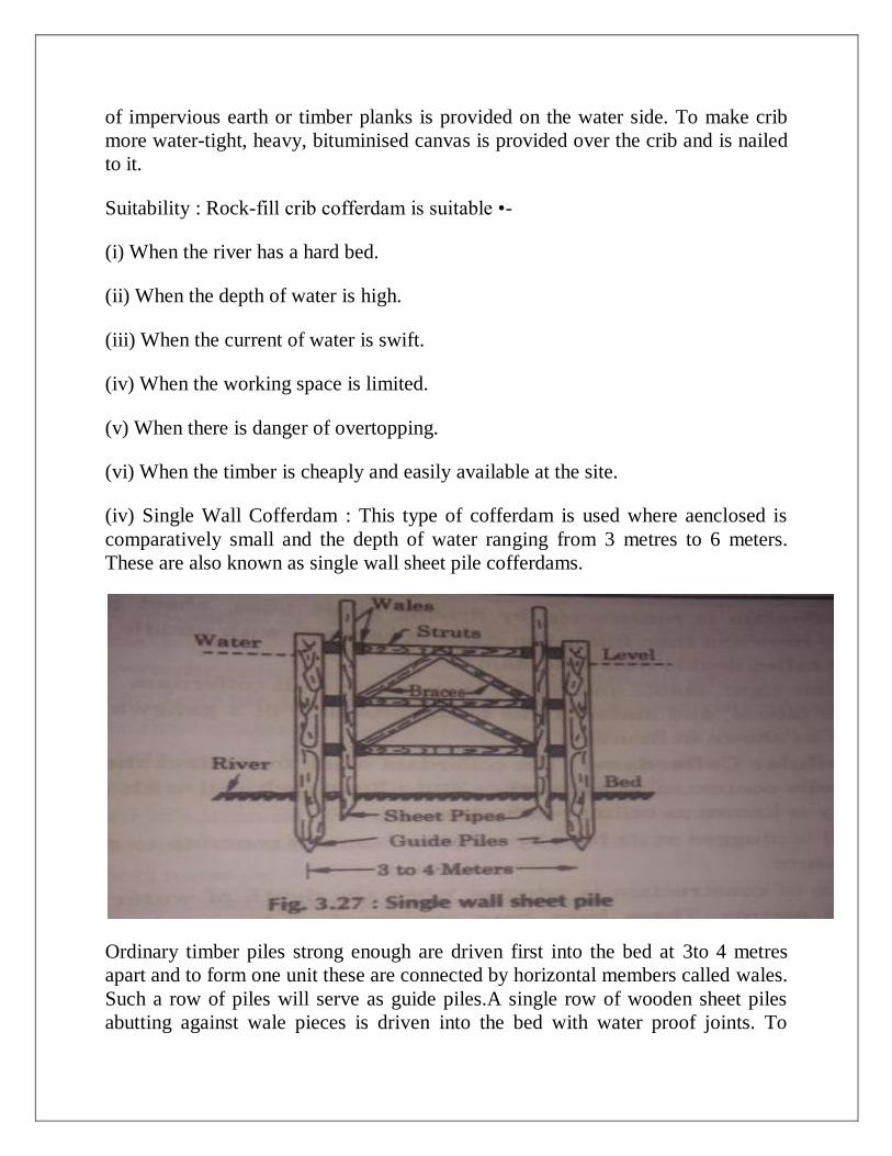
of impervious earth or timber planks is provided on the water side. To make crib
more water-tight, heavy, bituminised canvas is provided over the crib and is nailed
to it.
Suitability : Rock-fill crib cofferdam is suitable •-
(i) When the river has a hard bed.
(ii) When the depth of water is high.
(iii) When the current of water is swift.
(iv) When the working space is limited.
(v) When there is danger of overtopping.
(vi) When the timber is cheaply and easily available at the site.
(iv) Single Wall Cofferdam : This type of cofferdam is used where aenclosed is
comparatively small and the depth of water ranging from 3 metres to 6 meters.
These are also known as single wall sheet pile cofferdams.
Ordinary timber piles strong enough are driven first into the bed at 3to 4 metres
apart and to form one unit these are connected by horizontal members called wales.
Such a row of piles will serve as guide piles.A single row of wooden sheet piles
abutting against wale pieces is driven into the bed with water proof joints. To
strengthen this enclosure of sheets struts and braces are inserted in between the
opposite walls. As an alternative either earthen embankment or sand bags are
dumped all around its inside. The area so enclosed is worked usual way after
dewatering.
Guide piles are the vertical members which are embedded in river bed to support
sheet piles. These are made of timber or steel.
Sheet piles are thin sheets made of steel, or timber of R.C.C. etc driven into ground
to make enclosed area to be water tight.
(v) Double Wall Cofferdams : When the current of water is swift and also the
depth is from 6 metres to 12 metres, a single sheet pile coffer dam cannot
Withstand the hydraulic pressure. In this case two rows of single sheet piles at a
distance of 3 to 5 metres apart depending upon the depth of water are driven in a
similar way as explained below. The inner space between the two rows of sheet
piles is filled with earth. The area is then dewatered and construction started.
This cofferdam is constructed by driving guide piles, sheet piles along with wales
in two rows and then filling the space in between with puddle to form a water tight
wall is called double wall cofferdam.
It is water-tight, stable and useful than single wall cofferdam. It provides
movement of labour, and material due to the provision of a gangway.
(vi) Cellular Cofferdams : The cofferdam made from steel sheet piles forming a
series of cells connected to each other and filling each cell with clay or sand for
their stability is known as cellular cofferdam.
Each cell is plugged at its base by a layer of cement concrete to make it resistant to
water pressure.
Such type of construction is adopted when the depth of water ranges from 15
metres to 20 metres. These have been explained under steel sheet piles. Such
cofferdams consist of series of cells connected to each other and are filled with
earth to prevent dislocation or overturning. These are suitable when larger area is
required to be enclosed. Various other types are :—
(i) Diaphragm type
(ii) Circular type

TUNNELS
TUNNEL ENGINEERING:
It is the branch of civil engineering which deal with the construction design and
maintenance of tunnel.
Tunnel engineering is very complicated and large.
TUNNEL
Tunnels are artificial underground passage construction for the transportation
purpose . Without disturbing the ground surface.
CHRONOLOGICAL DEVELOPMENT OF TUNNELING
B.C. 2000 : First tunnel built in Babylon. It was 900 meters long With3.5 x 4.5 m
section.
A.D. 50 : Roman Emperor built the first Roman tunnel, 6 km long With 3 x 1.8 m
section.
1679 A.D.: First Navigational tunnel constructed by France about 160 m long.
1853 A.D.: First Highway tunnel constructed in Hungry and was 350 m long.
1949 A.D. : In Great Britain first underground railway tunnel wasconstructed
which is about 15.20 km long.
Advantages of Tunnels
(1) Tunnels are used for transportation of men, materials, goods and water.
(2) Tunnels are used for conveying water for hydro power plants to generate
power.
(3) Tunnels are used for carrying sewerage, gas etc.
NECESSITY OF TUNNELS
Necessity of tunnels arise any or combination of the following factors.
1. To Reduce the costs of Operations :
(i) In case of surface routes profiles of ground are followed which needs gradients
in alignment. In the absence of such gradients tunnels are constructed to reduce the
operation costs.
(ii) Tunnels also reduces lengths of surface routes thus results in economy of fuel,
time and cost of operation.
2. To reduce the cost of construction i.e. when depth of open cut is more than 20 m
it is advisable to adopt tunnels.
3. When surface route for reaching the other end become much longer therefore
costlier in construction, alternate route of through tunneling is provided.
4. When there is possibility that tunnel cost in some cases under the river is much
cheaper than to construct a bridge over the river.
5. In case of congested towns it is cheaper to construct the tunnel than surface
route due to non availability of land.
6. Sometimes tunnels are work out to be cheaper than open channels for conveying
water because of their short and direct routes.
7. When high mountain ridges are required to be crossed.
8. When an open cut threatens the stability of a near by structure a tunnel may he
provided.
9. Traffic facilities in tunnels are protected from hazards caused by snow, rain land
slide, warfare etc.
10. Traffic in underground tunnels does not interfere with surface traffic, and
provide easy movements.
REQUISITES OF TUNNEL
Requisites of tunnel are :
(i) Construction of the tunnel should be avoided on curves.
(ii) Shafts should be driven at regular intervals in such a way that the load for the
materials is less.
(iii) Alignment of the tunnel should be straight.
(iv) Tunnel construction is considered to be the best if it runs through hard rock as
no lining will be needed in this case.
(v) Tunnel should be given as steep slope as possible in longitudinal direction. It
will increase the velocity of transporting material and will need less cross-sectional
area.
Advantages and Disadvantages of tunnels are described below :-
(A) Advantages :-
(i)Tunnels connects two terminals by the shortest possible route.
(ii) Tunnels helps in avoiding the holding up of traffic due to congestion and
provide easy movements of traffic in big cities.
(iii) Tunnels proves economy in construction and operational cost when open
cut is more than 20 m.
(iv) Tunnels carry public utilities like water, gas etc across the river /
mountains very economically.
(v) Tunnels avoid dangerous open cuts likely to be subjected to snowfall DI'
land slides etc.
(vi) Tunnels protects the acquisition of valuable land.
(vii) Tunnels facilitate conduction of water to generate power

DISADVANTAGES
(i) It requires special equipment for their construction.
(ii) It require skilled labour and supervision in their construction.
(iii) These proves costlier in comparison to open cut.
(iv) It requires more time for their construction and completion.
COMPARISON BETWEEN TUNNEL AND OPEN CUT
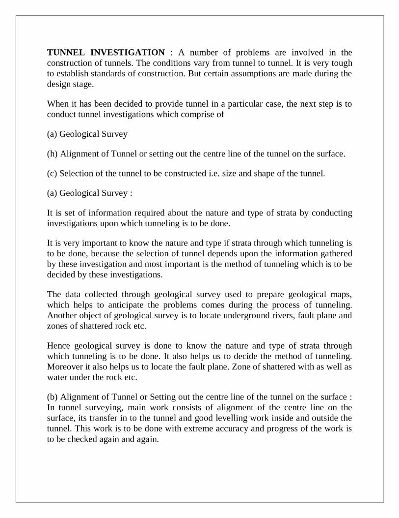
TUNNEL INVESTIGATION : A number of problems are involved in the
construction of tunnels. The conditions vary from tunnel to tunnel. It is very tough
to establish standards of construction. But certain assumptions are made during the
design stage.
When it has been decided to provide tunnel in a particular case, the next step is to
conduct tunnel investigations which comprise of
(a) Geological Survey
(h) Alignment of Tunnel or setting out the centre line of the tunnel on the surface.
(c) Selection of the tunnel to be constructed i.e. size and shape of the tunnel.
(a) Geological Survey :
It is set of information required about the nature and type of strata by conducting
investigations upon which tunneling is to be done.
It is very important to know the nature and type if strata through which tunneling is
to be done, because the selection of tunnel depends upon the information gathered
by these investigation and most important is the method of tunneling which is to be
decided by these investigations.
The data collected through geological survey used to prepare geological maps,
which helps to anticipate the problems comes during the process of tunneling.
Another object of geological survey is to locate underground rivers, fault plane and
zones of shattered rock etc.
Hence geological survey is done to know the nature and type of strata through
which tunneling is to be done. It also helps us to decide the method of tunneling.
Moreover it also helps us to locate the fault plane. Zone of shattered with as well as
water under the rock etc.
(b) Alignment of Tunnel or Setting out the centre line of the tunnel on the surface :
In tunnel surveying, main work consists of alignment of the centre line on the
surface, its transfer in to the tunnel and good levelling work inside and outside the
tunnel. This work is to be done with extreme accuracy and progress of the work is
to be checked again and again.
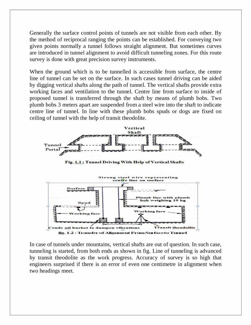
Generally the surface control points of tunnels are not visible from each other. By
the method of reciprocal ranging the points can be established. For conveying two
given points normally a tunnel follows straight alignment. But sometimes curves
are introduced in tunnel alignment to avoid difficult tunneling zones. For this route
survey is done with great precision survey instruments.
When the ground which is to be tunnelled is accessible from surface, the centre
line of tunnel can be set on the surface. In such cases tunnel driving can be aided
by digging vertical shafts along the path of tunnel. The vertical shafts provide extra
working faces and ventilation to the tunnel. Centre line from surface to inside of
proposed tunnel is transferred through the shaft by means of plumb bobs. Two
plumb bobs 3 meters apart are suspended from a steel wire into the shaft to indicate
centre line of tunnel. In line with these plumb bobs spuds or dogs are fixed on
ceiling of tunnel with the help of transit theodolite.
In case of tunnels under mountains, vertical shafts are out of question. In such case,
tunneling is started, from both ends as shown in fig. Line of tunneling is advanced
by transit theodolite as the work progress. Accuracy of survey is so high that
engineers surprised if there is an error of even one centimetre in alignment when
two headings meet.
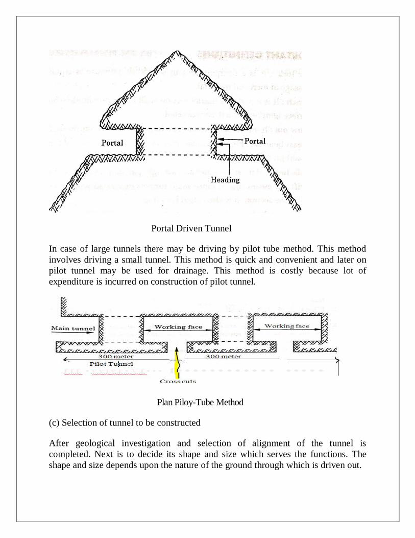
Portal Driven Tunnel
In case of large tunnels there may be driving by pilot tube method. This method
involves driving a small tunnel. This method is quick and convenient and later on
pilot tunnel may be used for drainage. This method is costly because lot of
expenditure is incurred on construction of pilot tunnel.
Plan Piloy-Tube Method
(c) Selection of tunnel to be constructed
After geological investigation and selection of alignment of the tunnel is
completed. Next is to decide its shape and size which serves the functions. The
shape and size depends upon the nature of the ground through which is driven out.
IMPORTANT DEFINITIONS
1. Air lock : It is a compartment in which air pressure is equalised to permit
passage of men and material,
2. Bench It is a part of a tunnel 4ection with the approximately horizontal upper
surface temporarily left unexcavated.
3. Blow out : It means sudden loss of a large amount of compressed air.
4. Breast boards : These are timber planks to support the face of tunnel excavation
in soft ground.
5. Bulk head : It means a water and air tight partition usually of steel.
6. Drift. : It means one or more small tunnels excavated with in and ahead of the
full cross-section. It is also caned Heading.
7. Face : It is the vertical surface at the head of a tunnel excavation.
8. Liner plate : It is a steel plate segment generally provided to support a tunnel
excavation.
9. Lining : It means temporary or permanent concrete structure in order to secure
and finish the tunnel interior.
10. Mucking : It means removal of material excavated or blasted from the tunnel
face.
11. Pilot tunnel : It is a small tunnel excavated over the whole length or over part
of a tunnel to explore sub-soil conditions and assist in final excavation.
12. Poling boards : These are timber or steel planks driven into the soft ground at
the tunnel face over supporting steel or timber sets to hold back soil during
excavation.
13. Scaling : It means removing loose pieces of rock from the tunnel surface after
blasting.
14. Shaft : It is a vertical excavation to gain access to tunnels or mines from the
surface.

15. Shotcrete : It is a concrete mixture sprayed on to the rock surface,
16. Wall plate : It is a footing placed on the rock shelf to temporarily support arch
ribs of tunnel sets.
17. Adit : It is a short transverse tunnel connecting two parallel tunnels or an entry
from the face of the slope to a side hill tunnel.
CLASSIFICATION OF TUNNELS
Tunnels are classified according to purpose for which they are constructed such as
(A) According to Service
1. High way tunnels
2. Railway tunnels
3. Rapid transit tunnels
4. Underground Caverns
5. Shafts
6. Special Tunnels
7. Aqueducts and Sewers
(B) According to locations
1. Under water tunnels
2. Mountain Tunnels
3. Shallow Tunnels
(C) According to Soil Type
1. Rock Tunnels
2. Soft ground tunnels
3. Mixed face tunnels
(D) According to Alignment
1. Saddle and base tunnels : When track is led through valleys, for reducing tunnel
length, as long as the natural slope of the valley does not become steeper than the
ruling gradient of the route, the tunnel is referred as saddle and base tunnels.
2. Spiral tunnels : These are those tunnels in which loop formation takes place into
the interior of mountain. These are provided in narrow valleys in order to obtain
additional length for minimum permissible radius.
3. Off-spur tunnels : These are those tunnels which are made to short cut minor
local obstacles. Such tunnels have very short lengths.
4. Slope tunnels : These are constructed to ensure safe operation and protection to
railway and highway routes in steep mountains. They have also been found
suitable from economic point.
(E) Miscellaneous tunnels all other types of tunnel come under this group such as
(i) Tunnels carrying gas, sewage, oil, telephone or electric cables etc.
(ii) Approach tunnels to underground installations and tunnels for defence
purposes.
(iii) Tunnels for pedestrian traffic
SIZE AND SHAPE OF TUNNELS
Size of Tunnels
Size of a tunnel is governed by the purpose of tunnel. The tunnel should be large
enough to discharge its function satisfactorily. Since lining reduces the size of
tunnel, allowance for lining is kept for deciding the size of tunnel to he actually
driven.
Shape of tunnel (sectional profile) is largely governed by the type and nature of
ground through which tunnel is driven. It is also influenced by purpose of tunnel.
Shape of tunnel should fulfill following requirements.
(a) Walls and roof of tunnel should be able to withstand external end internal
pressures to which they are likely to be subjected.
(h) Shape should be advantageous for the function of tunnel.
(c) Shape should be such that complicated tunnel supporting arrangements are
avoided.
Shapes of Tunnels
The shape of tunnel depends upon the type and nature of ground through which the
tunnel is to be driven. Its shape also depends upon the purpose for which it is to be
served. Shape of tunnels should be such that they are able to serve the purposes for
which they are constructed, more over shapes of tunnels must be such that they are
not liable for complicated frame work. The most important requirement is that
shape of tunnel should be able to with stand the pressures. Depending upon the
requirement and nature of the area, following shapes are commonly adopted
Shapes of Tunnels
(i) Poly-centric Tunnels (ii) Circular Tunnels (iii) Horse shoe Tunnels (iv) Egg-
shaped Tunnels (v) Elliptical Tunnels (vi) Box-type Tunnels (vii) Segmental
Tunnels
TUNNELING AND LINING
TUNNELING
The art of constructing a tunnel is known as tunneling.
Tunneling is very difficult and require skilled labour for their construction process.
Tunneling methods depends upon the type and nature of strata. Tunneling is
classified as
(A) Soft ground Tunneling
(B) Hard Rock Tunneling
(A) Soft ground or Soft Rock Tunneling
In this case of tunneling, after the excavation, it require immediate supporting to
support grounds as soon as possible. Excavation in soft rock is easy and cheap. The
various ways in which temporary supports are provided are
(i) Suitably spaced bent of wood
(ii) Suitably spaced bents of steel
(iii) Liner plates
(iv) Fore poling placed to retain the material between adjacent bents
In order to achieve economy, temporary supports are designed for higher working
stresses. Temporary supports are later on replaced by permanent lining. The face of
cannel in soft soil is attacked by excavating small bores at different places. These
bores arrangement thee enlarged to give full section of tunnel position of such
bores, timbering arrangement and method of enlargement of small bores, is
different in different countries and are named after the countries in which the have
been developed.
Tunneling in Hard Rock
In case of hard rock tunneling less timbering is required but need special care for
their excavation work. This case tunneling is comparatively costly but safe. These
require explosion during construction and progress of work is more. It require
heavy and costly equipment for constructing hard rock tunnels.
Methods of Tunneling in Soft Rock :
These are following methods of tunneling in soft rock.
(i) American Method
(ii) English Method
(iii) German Method
(iv) Belgian Method
(v) Italian Method etc
These are named because of their timbering arrangement and methods ()I
enlargement of small bores depending upon country to country and hence named
because of adoption of these methods by different countries.
Apart from these methods there are
(i) Fore poling method
(ii) Needle beam method
(iii) Linear plate method
(iv) Shield tunneling method
(v) Mechanical Tunnelling i.e. Mole Method
Shield tunnelling method become more popular in these days. But mole method is..
latest and known as mechanical method of tunnelling.
Needle Beam Method
This method is suitable for such ground which can stay unsupported for a few
minutes. The method derives from its name. The timber beams are used for
supporting the excavation temporarily.
The constructional procedure is explained in steps given below :
(1) A monkey drift about one meter deep is driven near the roof of tunnel.

(2) The root of monkey drift is supported with the help of trench jacks
(3) Needle beam is now inserted in drift. The rear end of beam is strutted as in fig
(4) The load of roof support is transferred to needle beam through a trench jack
(5) Now the drift is enlarged side ways and the new excavation is supported fig c
shows widening of drift on left side.
(6) When full section is excavated, new monkey drift is made for advancing the
tunnel further.
Excavation at the face is advanced as steep as the soil will stand. Steps are repeated
and the beam is advanced till the desired excavation work is complete.
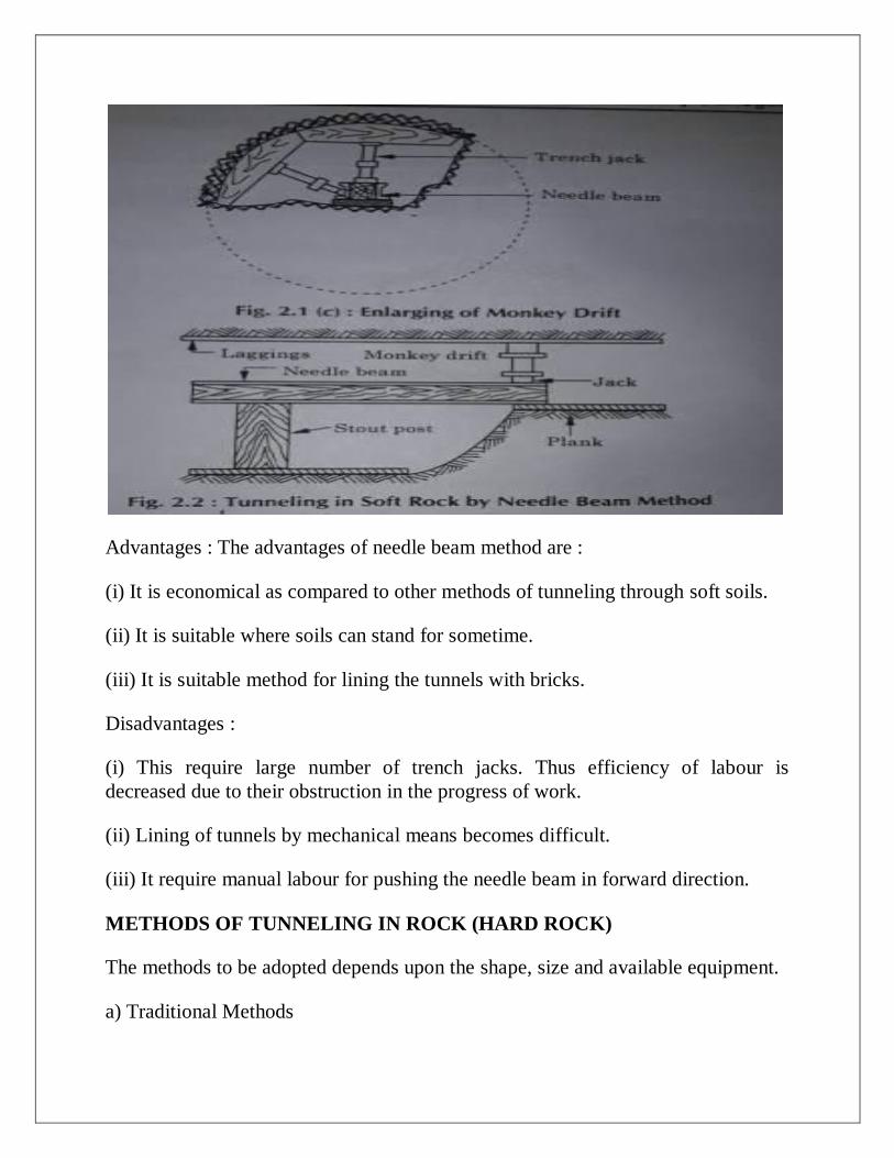
Advantages : The advantages of needle beam method are :
(i) It is economical as compared to other methods of tunneling through soft soils.
(ii) It is suitable where soils can stand for sometime.
(iii) It is suitable method for lining the tunnels with bricks.
Disadvantages :
(i) This require large number of trench jacks. Thus efficiency of labour is
decreased due to their obstruction in the progress of work.
(ii) Lining of tunnels by mechanical means becomes difficult.
(iii) It require manual labour for pushing the needle beam in forward direction.
METHODS OF TUNNELING IN ROCK (HARD ROCK)
The methods to be adopted depends upon the shape, size and available equipment.
a) Traditional Methods
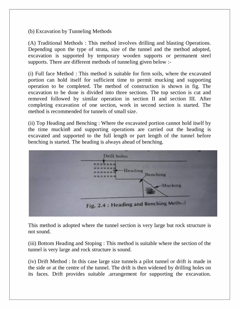
(b) Excavation by Tunneling Methods
(A) Traditional Methods : This method involves drilling and blasting Operations.
Depending upon the type of strata, size of the tunnel and the method adopted,
excavation is supported by temporary wooden supports or permanent steel
supports. There are different methods of tunneling given below :-
(i) Full face Method : This method is suitable for firm soils, where the excavated
portion can hold itself for sufficient time to permit mucking and supporting
operation to be completed. The method of construction is shown in fig. The
excavation to be done is divided into three sections. The top section is cut and
removed followed by similar operation in section II and section III. After
completing excavation of one section, work in second section is started. The
method is recommended for tunnels of small size.
(ii) Top Heading and Benching : Where the excavated portion cannot hold itself by
the time muckin8 and supporting operations are carried out the heading is
excavated and supported to the full length or part length of the tunnel before
benching is started. The heading is always ahead of benching.
This method is adopted where the tunnel section is very large but rock structure is
not sound.
(iii) Bottom Heading and Stoping : This method is suitable where the section of the
tunnel is very large and rock structure is sound.
(iv) Drift Method : In this case large size tunnels a pilot tunnel or drift is made in
the side or at the centre of the tunnel. The drift is then widened by drilling holes on
its faces. Drift provides suitable .arrangement for supporting the excavation.
Depending upon the position of the drift, the method of tunneling may be done
either.
(v) Wall plate drift : This method is adopted where rock is so bad. Wall plates of
sufficient lengths are provided to support the top ribs.
(B) Side Drift : It is adopted where size of tunnel is large and excavations needs to
be supported before mucking.
(C) Multiple Drift Method : This is the combination of side drift and top drift
method. This is frequently employed to get through crushed rock in fault zones
which may be behave like earth.
OPERATIONS INVOLVED IN TUNNELING
The hard rock tunneling method has following sequence of operation for
construction of tunnel.
(1) Drilling
(2) Loading of holes
(3) Blasting
(4) Scaling
(5) Mucking
(6) Secondary Blasting
(7) Tunnel Supporting
(8) Grouting and Lining
(1) Drilling Tunneling with explosive requires drilling of holes in to rock. These
holes are drilled. A drill holes are made with drills worked by compressed air. The
depth of the bore holes varies from 2.5 m to 3m. Holes are made by using Tack
drills either by jack hammer or drifter.
Generally holes are made along joints to loosen the rock material. The number of
holes to be drilled depends upon the area and nature of rock.
(2) Loading of Holes : Charging the holes with explosives is known as loading of
holes. It is the operation performed to loosen the rock, each hole is charged and
loaded with explosive. Explosives are used in the shape of cartridges. These
cartridges are fixed with detonators. These cartridges are known as primer
cartridges. Each hole needs one primer cartridge. Leads from detonators of various
holes are suitably connected to shot firing cable.
The quantity of explosive depends upon the type of strata to be blasted, kind of
explosive method of explosive.
(3) Blasting : After loading the holes neat step is blasting. A blasting lead is taken
up to safe, distance where it is connected to an exploder. Warning signals are
sounded for safety. After blasting a trained worker locate misfire, if any, and
reblasts it.
(4) Scaling : At the end of blasting some rock fragments hang loosely from ceiling
and walls of tunnel. These rock pieces may fall off without warning and cause
accidents during the operations. Removal of such loose rock fragments and
hammering off projecting pointed rock is known as scaling. It is done with the help
of steel rods and Water jets.
(5) Mucking : It refers to the operation of loading and removing the excavated or
blasted material and dumping it at the selected place. Mucking is the operation of
loading the rock, earth or any other excavated material. It may be done either by
Hand or by Machines.
The blasted debris is known as muck. Removal of muck and its disposal is mown
as mucking. Mucking involves
(i) Loading of Muck
(ii) Hauling
(iii) Unloading
Muck loaders are called muckers the operation of mucking is done either by I
manual labour, belt conveyor or mechanical shovels. A mucker is a mechanical
device.
Hauling of muck is done by mine cars. Mine cars are pulled with locomotives.,
Carts may be used on small jobs.
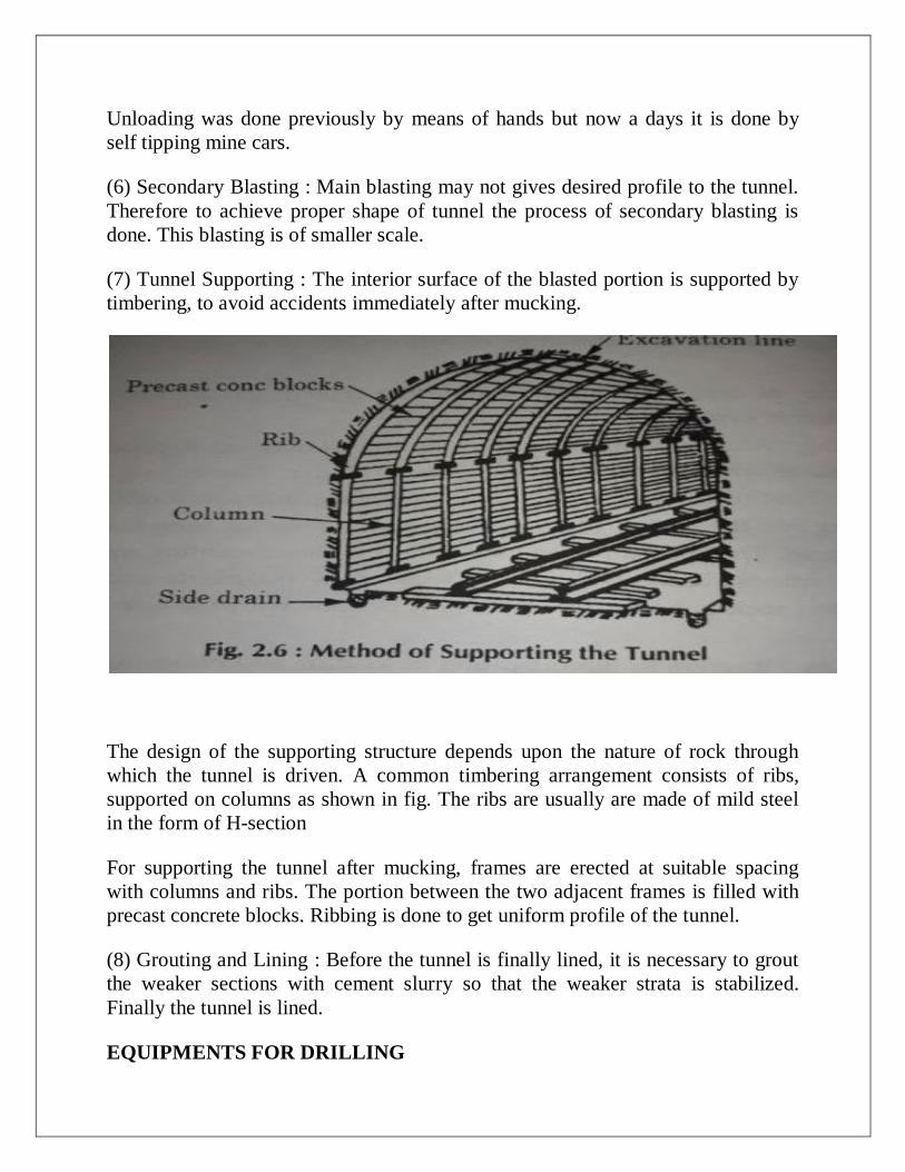
Unloading was done previously by means of hands but now a days it is done by
self tipping mine cars.
(6) Secondary Blasting : Main blasting may not gives desired profile to the tunnel.
Therefore to achieve proper shape of tunnel the process of secondary blasting is
done. This blasting is of smaller scale.
(7) Tunnel Supporting : The interior surface of the blasted portion is supported by
timbering, to avoid accidents immediately after mucking.
The design of the supporting structure depends upon the nature of rock through
which the tunnel is driven. A common timbering arrangement consists of ribs,
supported on columns as shown in fig. The ribs are usually are made of mild steel
in the form of H-section
For supporting the tunnel after mucking, frames are erected at suitable spacing
with columns and ribs. The portion between the two adjacent frames is filled with
precast concrete blocks. Ribbing is done to get uniform profile of the tunnel.
(8) Grouting and Lining : Before the tunnel is finally lined, it is necessary to grout
the weaker sections with cement slurry so that the weaker strata is stabilized.
Finally the tunnel is lined.
EQUIPMENTS FOR DRILLING
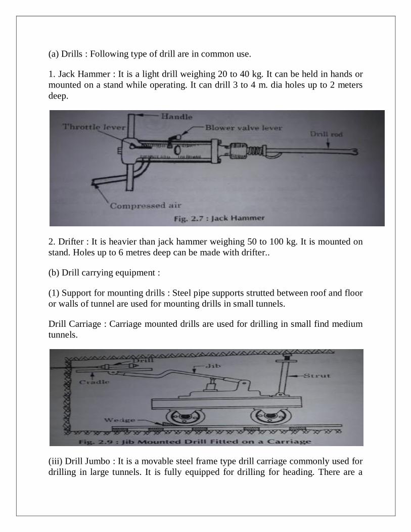
(a) Drills : Following type of drill are in common use.
1. Jack Hammer : It is a light drill weighing 20 to 40 kg. It can be held in hands or
mounted on a stand while operating. It can drill 3 to 4 m. dia holes up to 2 meters
deep.
2. Drifter : It is heavier than jack hammer weighing 50 to 100 kg. It is mounted on
stand. Holes up to 6 metres deep can be made with drifter..
(b) Drill carrying equipment :
(1) Support for mounting drills : Steel pipe supports strutted between roof and floor
or walls of tunnel are used for mounting drills in small tunnels.
Drill Carriage : Carriage mounted drills are used for drilling in small find medium
tunnels.
(iii) Drill Jumbo : It is a movable steel frame type drill carriage commonly used for
drilling in large tunnels. It is fully equipped for drilling for heading. There are a

number of platforms known as decks to support drillers and drilling steel. jumbo
moves on tracks which are of broader gauge than that of mine cars.