Embed Size (px)
Citation preview
AS 1085.21:2020
Please note this is a RISSB Australian Standard® draft
Document content exists for RISSB product development purposes only and should not be relied upon or considered as final published content.
Any questions in relation to this document or RISSB’s accredited development process should be referred to RISSB.
RISSB Office
Phone:
(07) 3724 0000 Overseas: +61 7 3724 0000
Email:
Web:
www.rissb.com.au
AS 1085.21 Assigned Standard Development Manager
Name:
Risharda Robertson
Phone:
0438 879 916
Email:
R a i l w a y t r a c k m a t e r i a l P a r t 2 1 :
T u r n o u t s , s w i t c h e s a n d c r o s s i n g s
Infrastructure Standard
AS 1085
.21
Railway
track
mate
rial P
art 21
: Turn
outs,
switc
hes a
nd cr
ossin
gs
Draft fo
r Pub
lic Com
ment
AS 1085.21:2020
Railway track material Part 21: Turnouts, switches and
crossings
RISSB ABN 58 105 001 465 Page 1 Accredited Standards Development Organisation
Notice to users
This RISSB product has been developed using input from rail experts from across the rail industry and represents good practice for the industry. The reliance upon or manner of use of this RISSB product is the sole responsibility of the user who is to assess whether it meets their organisation’s operational environment and risk profile.
AS 1085.21:2020
Railway track material Part 21: Turnouts, switches and crossings
Draft history (Draft history applies only during development)
Draft version Draft date Notes
PC Draft 20/12/2019 Draft for Public Comment
Copyright
© RISSB
All rights are reserved. No part of this work can be reproduced or copied in any form or by any means, electronic or mechanical, including photocopying, without the written permission of RISSB, unless otherwise permitted under the Copyright Act 1968.
Objective
The objective of this Standard is to provide information and requirements for the design and manufacture of turnouts, switches and crossings, and their components.
Turnout switches and crossings are vital track components that allow and control the safe diversion of rail vehicles from one track to another or to cross other tracks.
Compliance
There are two types of control contained within Australian Standards developed by RISSB:
1. Requirements.
2. Recommendations.
Requirements – it is mandatory to follow all requirements to claim full compliance with the Standard.
Requirements are identified within the text by the term ‘shall’.
Recommendations – do not mention or exclude other possibilities but do offer the one that is preferred. Recommendations are identified within the text by the term ‘should’.
Recommendations recognise that there could be limitations to the universal application of the control, i.e. the identified control is not able to be applied or other controls are more appropriate or better.
For compliance purposes, where a recommended control is not applied as written in the standard it could be incumbent on the adopter of the standard to demonstrate their actual method of controlling the risk as part of their WHS or Rail Safety National Law obligations. Similarly, it could also be incumbent on an adopter of the standard to demonstrate their method of controlling the risk to contracting entities, or interfacing organisations where the risk may be shared.
Controls in RISSB standards address known railway hazards are addressed in a Appendix A.
AS 1085
.21
Railway
track
mate
rial P
art 21
: Turn
outs,
switc
hes a
nd cr
ossin
gs
Draft fo
r Pub
lic Com
ment
AS 1085.21:2020
Railway track material Part 21: Turnouts, switches and crossings
RISSB ABN 58 105 001 465 Page 2 Accredited Standards Development Organisation
Contents
1 Scope and general ....................................................................................................... 4
1.1 Scope ............................................................................................................. 4
1.2 Referenced documents ................................................................................... 4
1.3 Definitions ....................................................................................................... 5
2 Turnout design ............................................................................................................. 7
2.1 General ........................................................................................................... 7
2.2 Design parameters .......................................................................................... 7
2.3 Tangential ..................................................................................................... 15
2.4 Secant .......................................................................................................... 20
3 Interfaces .................................................................................................................. 23
3.1 General ......................................................................................................... 23
3.2 Operating equipment .................................................................................... 23
3.3 Insulation ...................................................................................................... 24
3.4 Installation .................................................................................................... 24
3.5 Track and structure interfaces ....................................................................... 24
4 Manufacture ............................................................................................................... 25
4.1 Materials, tests and standards ...................................................................... 25
4.2 Rails, fishplates and sleeper plates ............................................................... 25
4.3 Castings ........................................................................................................ 25
4.4 Steel and iron castings .................................................................................. 26
4.5 Manganese steel castings ............................................................................. 26
4.6 Fastening ...................................................................................................... 30
4.7 Flame cutting ................................................................................................ 31
4.8 Welding ......................................................................................................... 31
4.9 Hardening ..................................................................................................... 31
4.10 Rail drilling .................................................................................................... 32
4.11 Sawing and machining .................................................................................. 32
4.12 Riveting ......................................................................................................... 32
4.13 Fitting ............................................................................................................ 32
4.14 Forgings ........................................................................................................ 32
4.15 Cast iron blocks ............................................................................................ 32
4.16 Cast steel blocks ........................................................................................... 32
4.17 Special heel bolt ferrules ............................................................................... 33
4.18 Nylon bushes ................................................................................................ 33
4.19 Epoxy gluing of crossings ............................................................................. 33
4.20 Switch assembly ........................................................................................... 33
4.21 Crossing assembly ........................................................................................ 33
4.22 Tolerances .................................................................................................... 34
4.23 Stamping ...................................................................................................... 36
4.24 Match marking .............................................................................................. 37
4.26 Final assembly and inspection ...................................................................... 37
AS 1085
.21
Railway
track
mate
rial P
art 21
: Turn
outs,
switc
hes a
nd cr
ossin
gs
Draft fo
r Pub
lic Com
ment
AS 1085.21:2020
Railway track material Part 21: Turnouts, switches and crossings
RISSB ABN 58 105 001 465 Page 3 Accredited Standards Development Organisation
4.27 Preparation for dispatch ................................................................................ 37
5 Product acceptance .................................................................................................... 38
5.1 General ......................................................................................................... 38
5.2 Type approval ............................................................................................... 38
5.3 Certificate of compliance ............................................................................... 38
5.4 Trial assembly ............................................................................................... 38
5.5 Assembly maintenance manuals and drawings ............................................. 38
Appendix Contents
Appendix A Hazard register ........................................................................................... 39
Appendix B Terminology and drawings .......................................................................... 40
Appendix C Information to be supplied by the purchaser ................................................ 59
Appendix D Bibliography ................................................................................................ 63
AS 1085
.21
Railway
track
mate
rial P
art 21
: Turn
outs,
switc
hes a
nd cr
ossin
gs
Draft fo
r Pub
lic Com
ment
AS 1085.21:2020
Railway track material Part 21: Turnouts, switches and crossings
RISSB ABN 58 105 001 465 Page 4 Accredited Standards Development Organisation
1 Scope and general
1.1 Scope
This standard specifies requirements for the design and manufacture of turnouts, switches and crossings, and their components.
This standard does not cover management of turnouts, switches and crossings during other stages of the asset’s lifecycle such as installation and maintenance.
1.2 Referenced documents
1.2.1 Normative references
The following documents are referred to in the text in such a way that some or all of their content constitutes requirements of this document:
• AS 1085.1 Railway track materials, Part 1: Steel rails
• AS 1085.2 Railway track materials, Part 2: Fishplates
• AS 1085.3 Railway track materials, Part 13: Sleeper plates
• AS 1085.4 Railway track materials, Part 4: Fishbolts and nuts
• AS 1085.12 Railway track materials, Part 12: Insulated joint assemblies
• AS 1085.14 Railway track materials, Part 14: Prestressed concrete sleepers
• AS 1085.17 Railway track materials, Part 17: Steel sleepers
• AS 1442 Carbon steels and carbon-manganese steels—Hot rolled bars and semi-finished products.
• AS 1816 Metallic materials.
• AS 1830 Grey cast iron.
• AS 1831 Ductile cast iron.
• AS 1988 Welding of ferrous castings.
• AS 2074 Cast steels.
• AS 2205.1 Methods for destructive testing of welds in metal, Part 1: Macro metallographic test for cross-section examination.
• AS/NZS 1252 High strength steel bolts with associated nuts and washers for structural engineering.
• AS/NZS 1554.1 Structural steel welding, Part 1: Welding of steel structures.
• AS/NZS 3679.1 Structural steel, Part 1: Hot-rolled bars and sections.
• AWS 5.13 Specification for Surfacing Electrodes for Shielded Metal Arc Welding.
• AWS 5.21 Specification for Bare Electrodes and Rods for Surfacing.
AS 1085
.21
Railway
track
mate
rial P
art 21
: Turn
outs,
switc
hes a
nd cr
ossin
gs
Draft fo
r Pub
lic Com
ment
AS 1085.21:2020
Railway track material Part 21: Turnouts, switches and crossings
RISSB ABN 58 105 001 465 Page 5 Accredited Standards Development Organisation
1.3 Definitions
For the purposes of this document, the terms and definitions given in RISSB Glossary: https://www.rissb.com.au/products/glossary/ and the following apply:
(a) anti creep device a device used to minimize and monitor longitudinal creep between switch blade and stockrail
(b) asymmetric rail non-symmetric shaped rail of low height and thick web
(c) block casting or fabricated steel component used to support rail components at a fixed distance apart
(d) cant deficiency The difference between the applied cant on the track and the equilibrium cant for the rolling stock at a particular speed.
(e) check rail a steel section placed inside the running rail which comes into contact with the back of the wheel flange, to guide the wheels through points and crossings.
NOTES:
1. check rails can be manufactured from rail.
2. A checkrail may be raised above the level of the running rail (i.e. the top of the checkrail is above
the running rail).
(f) closure rails rails making up a turnout or special trackwork diamond configuration that are apart from those in the switch assemblies, crossings and checkrail units
(g) crossing a track component that enables a wheel travelling along one rail to pass through the rail of a track which crosses its path.
NOTE: The most common types are ‘V’ and ‘K’. See section X for further information.
(h) heat affected zone section of the parent rail outside the fusion zone that has mechanical properties altered by the welding process
(i) interlocking interaction of equipment controlling switches and/or signals to prevent conflicting movements, and to make sure that routes are set correctly.
(j) machining allowance extra material required as a raw casting
(k) stockrail A length of rail providing support for the switch and acts as the running rail when switch is open.
(l) switch assembly a track component that provides a path for a wheel to transfer from one track to another and usually consists of a section of bent and planed rail (known as the switch rail) and its connecting parts (for example switch rod brackets, reinforcing bars and high strength tips where appropriate).
AS 1085
.21
Railway
track
mate
rial P
art 21
: Turn
outs,
switc
hes a
nd cr
ossin
gs
Draft fo
r Pub
lic Com
ment
AS 1085.21:2020
Railway track material Part 21: Turnouts, switches and crossings
RISSB ABN 58 105 001 465 Page 6 Accredited Standards Development Organisation
(m) switchblade a machined tapered rail that allows the direction of a train to be altered to another line.
(n) turnout a complete track assembly that allows rolling stock to converge or diverge into or from a single track (respectively)
AS 1085
.21
Railway
track
mate
rial P
art 21
: Turn
outs,
switc
hes a
nd cr
ossin
gs
Draft fo
r Pub
lic Com
ment
AS 1085.21:2020
Railway track material Part 21: Turnouts, switches and crossings
RISSB ABN 58 105 001 465 Page 7 Accredited Standards Development Organisation
2 Turnout design
2.1 General
The aim of turnout design is to provide a suitable product for the purchaser’s application. The factors for consideration include, but are not limited to:
(a) minimizing dynamic wheel/rail forces;
(b) optimizing whole-of-life turnout and reduced maintenance;
(c) ensuring that there is an adequate safety factor for design speed through turnouts, for given cant deficiencies, turnout angle and radii; and
(d) interfacing with other structures or equipment. (Refer to Section 3 on interfaces).
There are a number of design geometric configurations. Two typical geometric designs are covered in this Section (secant and tangential).
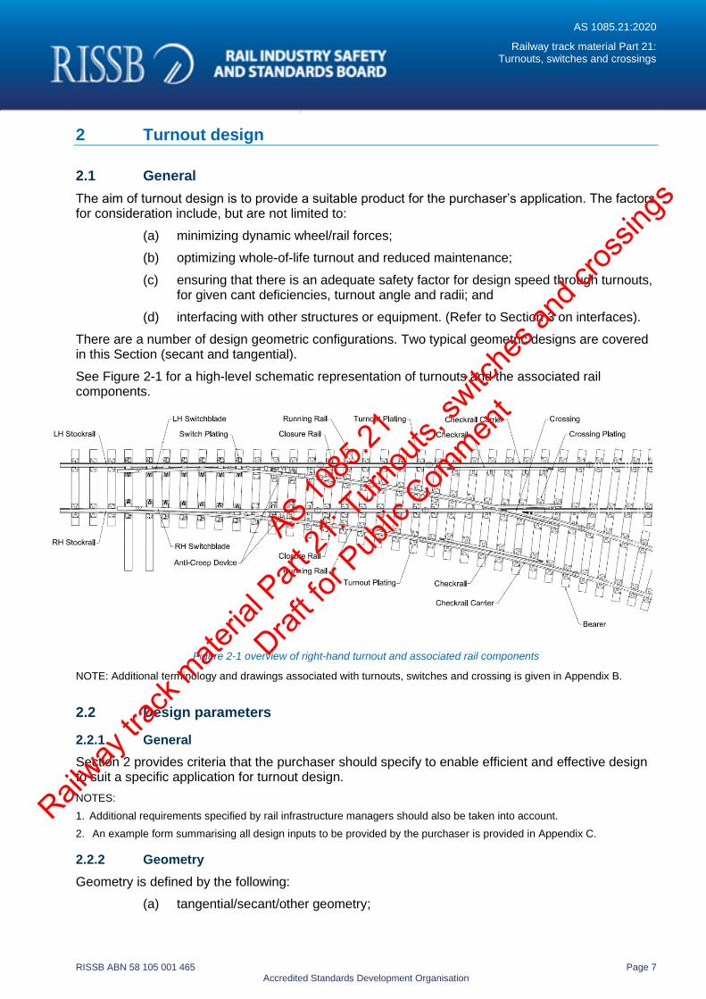
See Figure 2-1 for a high-level schematic representation of turnouts and the associated rail components.
Figure 2-1 overview of right-hand turnout and associated rail components
NOTE: Additional terminology and drawings associated with turnouts, switches and crossing is given in Appendix B.
2.2 Design parameters
2.2.1 General
Section 2 provides criteria that the purchaser should specify to enable efficient and effective design to suit a specific application for turnout design.
NOTES:
1. Additional requirements specified by rail infrastructure managers should also be taken into account.
2. An example form summarising all design inputs to be provided by the purchaser is provided in Appendix C.
2.2.2 Geometry
Geometry is defined by the following:
(a) tangential/secant/other geometry;
AS 1085
.21
Railway
track
mate
rial P
art 21
: Turn
outs,
switc
hes a
nd cr
ossin
gs
Draft fo
r Pub
lic Com
ment
AS 1085.21:2020
Railway track material Part 21: Turnouts, switches and crossings
RISSB ABN 58 105 001 465 Page 8 Accredited Standards Development Organisation
(b) crossing/turnout angle;
(c) turnout handing;
(d) turnout radius;
(e) mainline radius (if applicable);
(f) track layout.
2.2.3 Gauge
Generally, the track gauge will be one of the following:
(a) broad (1600 mm);
(b) standard (1435 mm);
(c) narrow (1067 mm);
(d) other gauge to be nominated.
2.2.4 Rail weight/section
Refer to AS 1085.1 for current Australian rail section rail weight. Other rail sections may be nominated with reference to the relevant standard:
(a) Switchblade - in certain applications, typically tangential turnouts, the switchblade may use an asymmetric rail section which varies from the rail used in the turnout.
(b) Crossing - some swing nose and fixed nose crossings may use a non-standard rail. This section is to be nominated.
(c) Checkrail - elevated checkrail section may be used in place of standard full depth rail section. This section is to be nominated.
2.2.5 Crossing type
The crossing type is determined according to rail infrastructure manager’s specifications. (Refer to section B.7 for crossing-type options.)
2.2.6 Switch type
The switch type is determined according to rail infrastructure manager’s specifications. (Refer to B.21.3 and B.21.5).
2.2.7 Bearer type
The bearer type is determined according to rail infrastructure manager’s specifications. (Refer to B.2).
2.2.8 Fastening system
The fastening system type is determined according to rail infrastructure manager’s specifications. (Refer to section B.11).
2.2.9 Wheel rail interface
The wheel rail interface is determined according to rail infrastructure manager’s specification for:
(a) wheel sections;
(b) wheel back-to-back dimension;
(c) flangeway width;
AS 1085
.21
Railway
track
mate
rial P
art 21
: Turn
outs,
switc
hes a
nd cr
ossin
gs
Draft fo
r Pub
lic Com
ment
AS 1085.21:2020
Railway track material Part 21: Turnouts, switches and crossings
RISSB ABN 58 105 001 465 Page 9 Accredited Standards Development Organisation
(d) flangeway depth;
(e) check rail effectiveness
2.2.10 Operating parameters
The operating parameters are determined from the rail infrastructure manager’s requirements for:
(a) axle load - maximum tonnage per axle;
(b) speed - maximum mainline and diverge operating speeds.
2.2.11 Cant deficiency
Generally, the following cant deficiencies will apply unless otherwise nominated:
(a) Broad gauge (1600 mm) cant deficiency - 90 mm.
(b) Standard gauge (1435 mm) cant deficiency - 75 mm.
(c) Narrow gauge (1067 mm) cant deficiency - 55 mm.
2.2.12 Nominal design life
Measured in years and/or million gross tonnes.
2.2.13 Signalling interfaces
The following signalling interfaces:
(a) Switch machine type and location.
(b) Locking mechanism.
(c) Detection type.
(d) Location and details of fixing points for switch, stock, swing nose crossing, drilling and machining.
(e) Location and details of fixing points for bearers.
(f) Requirements for insulated joints. (To be nominated.)
(Refer to Section 3 for other interfacing considerations.)
2.2.14 Railway infrastructure clearances
Railway infrastructure clearances as calculated in accordance with AS 7633.
2.2.15 Noise and vibration
When switch and crossing assemblies are to be installed in residential or built-up areas where noise and vibration can be an issue, consideration should be given to the use of slab track and an attenuation type system. Introduction of swing nose crossings can also reduce noise and vibration.
AS 1085
.21
Railway
track
mate
rial P
art 21
: Turn
outs,
switc
hes a
nd cr
ossin
gs
Draft fo
r Pub
lic Com
ment
AS 1085.21:2020
Railway track material Part 21: Turnouts, switches and crossings
RISSB ABN 58 105 001 465 Page 10 Accredited Standards Development Organisation
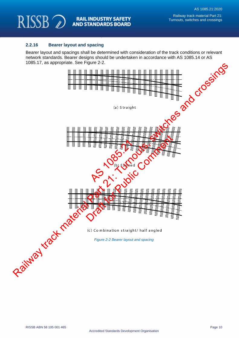
2.2.16 Bearer layout and spacing
Bearer layout and spacings shall be determined with consideration of the track conditions or relevant network standards. Bearer designs should be undertaken in accordance with AS 1085.14 or AS 1085.17, as appropriate. See Figure 2-2.
Figure 2-2 Bearer layout and spacing
AS 1085
.21
Railway
track
mate
rial P
art 21
: Turn
outs,
switc
hes a
nd cr
ossin
gs
Draft fo
r Pub
lic Com
ment
AS 1085.21:2020
Railway track material Part 21: Turnouts, switches and crossings
RISSB ABN 58 105 001 465 Page 11 Accredited Standards Development Organisation
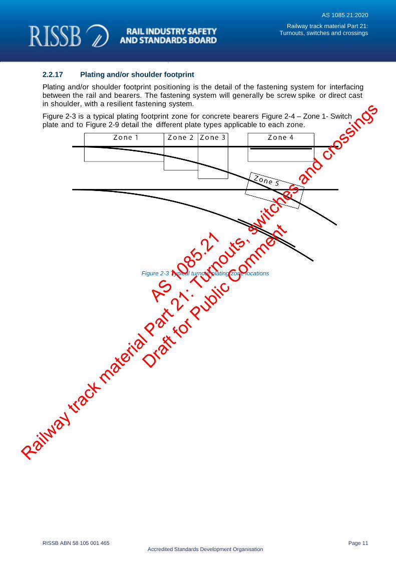
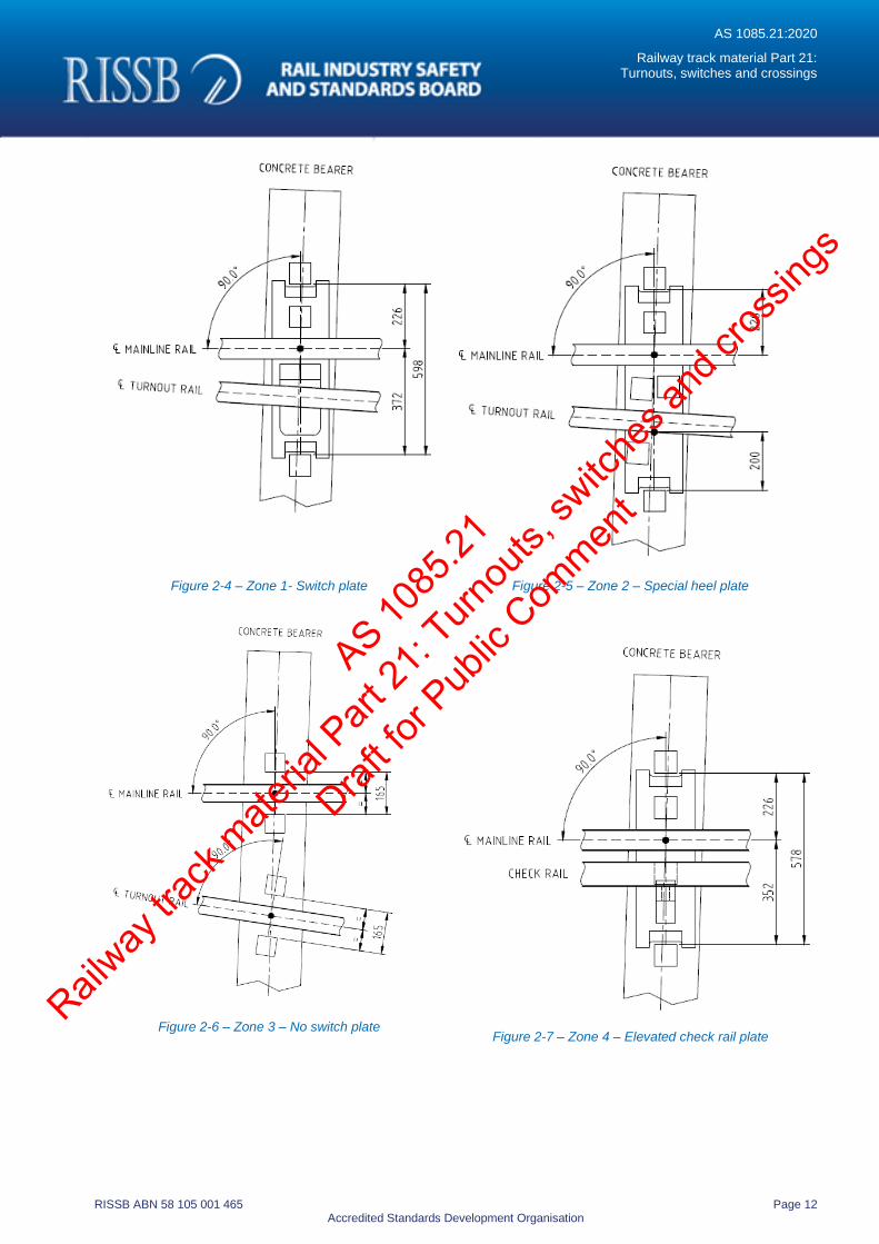
2.2.17 Plating and/or shoulder footprint
Plating and/or shoulder footprint positioning is the detail of the fastening system for interfacing between the rail and bearers. The fastening system will generally be screw spike or direct cast in shoulder, with a resilient fastening system.
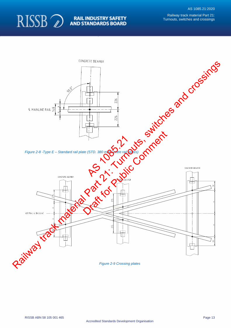
Figure 2-3 is a typical plating footprint zone for concrete bearers Figure 2-4 – Zone 1- Switch plate and to Figure 2-9 detail the different plate types applicable to each zone.
Figure 2-3 Typical turnout plating zone locations
AS 1085
.21
Railway
track
mate
rial P
art 21
: Turn
outs,
switc
hes a
nd cr
ossin
gs
Draft fo
r Pub
lic Com
ment
AS 1085.21:2020
Railway track material Part 21: Turnouts, switches and crossings
RISSB ABN 58 105 001 465 Page 12 Accredited Standards Development Organisation
Figure 2-4 – Zone 1- Switch plate
Figure 2-5 – Zone 2 – Special heel plate
Figure 2-6 – Zone 3 – No switch plate
Figure 2-7 – Zone 4 – Elevated check rail plate
AS 1085
.21
Railway
track
mate
rial P
art 21
: Turn
outs,
switc
hes a
nd cr
ossin
gs
Draft fo
r Pub
lic Com
ment
AS 1085.21:2020
Railway track material Part 21: Turnouts, switches and crossings
RISSB ABN 58 105 001 465 Page 13 Accredited Standards Development Organisation
Figure 2-8 -Type E – Standard rail plate (STD. 380 mm Centre rail plates)
Figure 2-9 Crossing plates
AS 1085
.21
Railway
track
mate
rial P
art 21
: Turn
outs,
switc
hes a
nd cr
ossin
gs
Draft fo
r Pub
lic Com
ment
AS 1085.21:2020
Railway track material Part 21: Turnouts, switches and crossings
RISSB ABN 58 105 001 465 Page 14 Accredited Standards Development Organisation
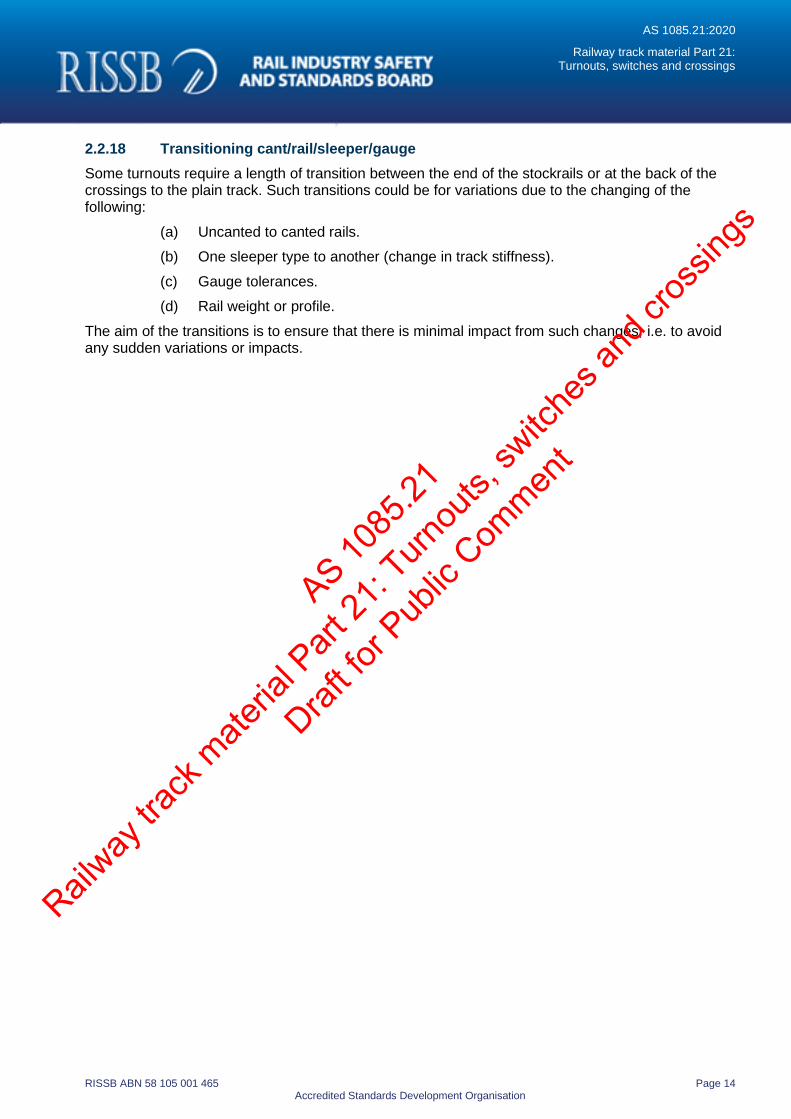
2.2.18 Transitioning cant/rail/sleeper/gauge
Some turnouts require a length of transition between the end of the stockrails or at the back of the crossings to the plain track. Such transitions could be for variations due to the changing of the following:
(a) Uncanted to canted rails.
(b) One sleeper type to another (change in track stiffness).
(c) Gauge tolerances.
(d) Rail weight or profile.
The aim of the transitions is to ensure that there is minimal impact from such changes, i.e. to avoid any sudden variations or impacts.
AS 1085
.21
Railway
track
mate
rial P
art 21
: Turn
outs,
switc
hes a
nd cr
ossin
gs
Draft fo
r Pub
lic Com
ment
AS 1085.21:2020
Railway track material Part 21: Turnouts, switches and crossings
RISSB ABN 58 105 001 465 Page 15 Accredited Standards Development Organisation
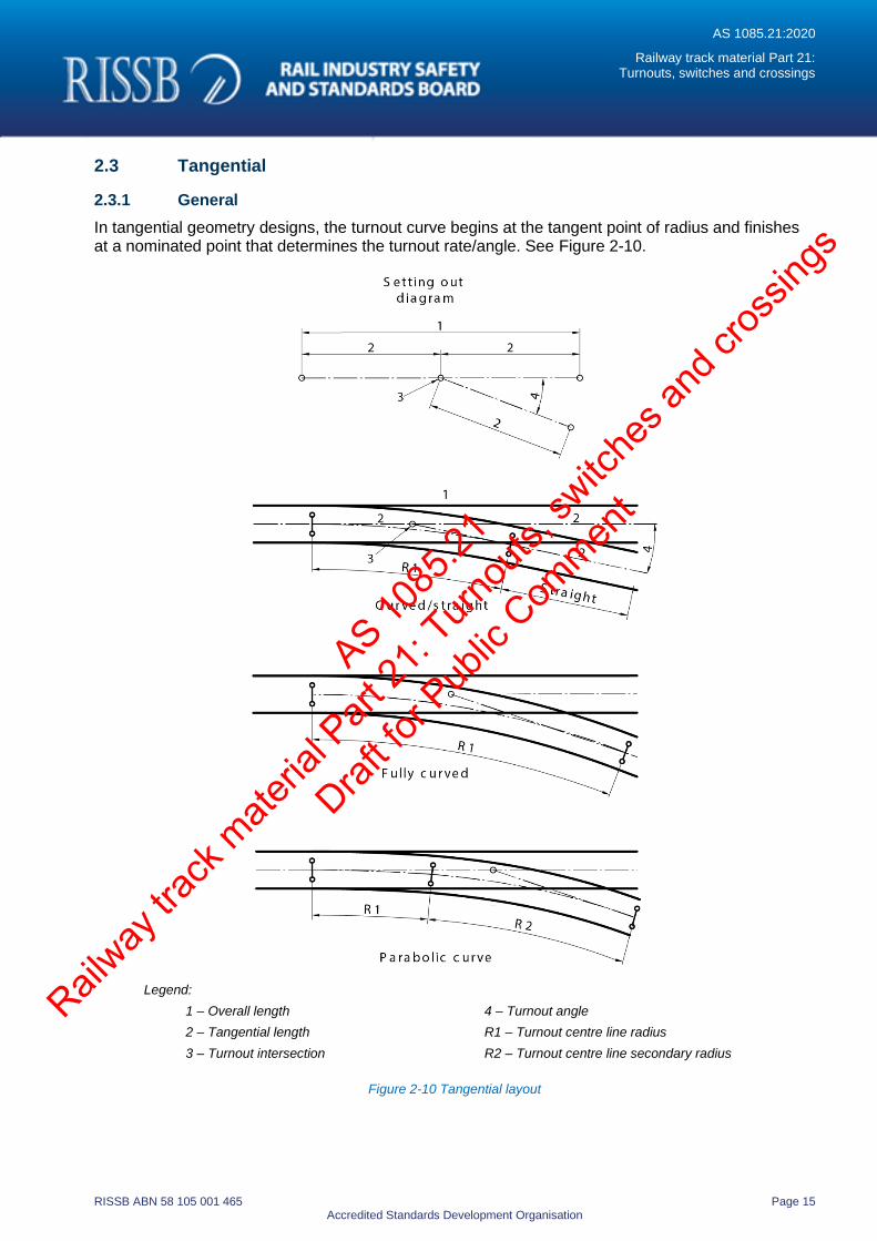
2.3 Tangential
2.3.1 General
In tangential geometry designs, the turnout curve begins at the tangent point of radius and finishes at a nominated point that determines the turnout rate/angle. See Figure 2-10.
Legend:
1 – Overall length 4 – Turnout angle
2 – Tangential length R1 – Turnout centre line radius
3 – Turnout intersection R2 – Turnout centre line secondary radius
Figure 2-10 Tangential layout
AS 1085
.21
Railway
track
mate
rial P
art 21
: Turn
outs,
switc
hes a
nd cr
ossin
gs
Draft fo
r Pub
lic Com
ment
AS 1085.21:2020
Railway track material Part 21: Turnouts, switches and crossings
RISSB ABN 58 105 001 465 Page 16 Accredited Standards Development Organisation
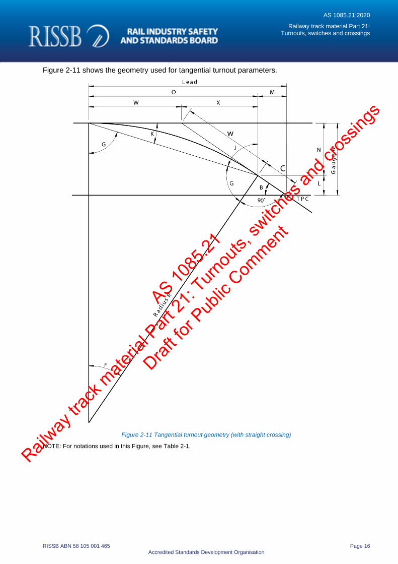
Figure 2-11 shows the geometry used for tangential turnout parameters.
Figure 2-11 Tangential turnout geometry (with straight crossing)
NOTE: For notations used in this Figure, see Table 2-1.
AS 1085
.21
Railway
track
mate
rial P
art 21
: Turn
outs,
switc
hes a
nd cr
ossin
gs
Draft fo
r Pub
lic Com
ment
AS 1085.21:2020
Railway track material Part 21: Turnouts, switches and crossings
RISSB ABN 58 105 001 465 Page 17 Accredited Standards Development Organisation
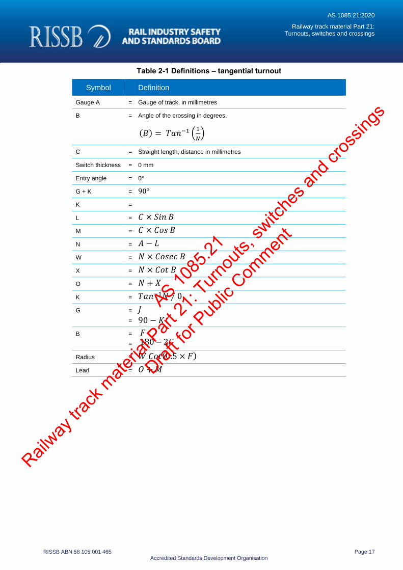
Table 2-1 Definitions – tangential turnout
Symbol Definition
Gauge A = Gauge of track, in millimetres
B = Angle of the crossing in degrees.
(𝐵) = 𝑇𝑎𝑛−1 (1
𝑁)
C = Straight length, distance in millimetres
Switch thickness = 0 mm
Entry angle = 0°
G + K = 90°
K =
L = 𝐶 × 𝑆𝑖𝑛 𝐵
M = 𝐶 × 𝐶𝑜𝑠 𝐵
N = 𝐴 − 𝐿
W = 𝑁 × 𝐶𝑜𝑠𝑒𝑐 𝐵
X = 𝑁 × 𝐶𝑜𝑡 𝐵
O = 𝑁 + 𝑋
K = 𝑇𝑎𝑛−1𝑁 ∕ 0
G =
=
𝐽
90 − 𝐾
B =
=
𝐹 180 − 2𝐺
Radius = 𝑊 𝐶𝑜𝑡(0.5 × 𝐹)
Lead = 𝑂 + 𝑀
AS 1085
.21
Railway
track
mate
rial P
art 21
: Turn
outs,
switc
hes a
nd cr
ossin
gs
Draft fo
r Pub
lic Com
ment
AS 1085.21:2020
Railway track material Part 21: Turnouts, switches and crossings
RISSB ABN 58 105 001 465 Page 18 Accredited Standards Development Organisation
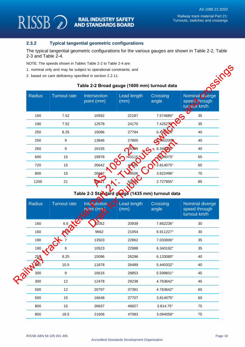
2.3.2 Typical tangential geometric configurations
The typical tangential geometric configurations for the various gauges are shown in Table 2-2, Table 2-3 and Table 2-4.
NOTE: The speeds shown in Tables Table 2-2 to Table 2-4 are:
1. nominal only and may be subject to operational constraints; and
2. based on cant deficiency specified in section 2.2.11.
Table 2-2 Broad gauge (1600 mm) turnout data
Radius
Turnout rate Intersection point (mm)
Lead length (mm)
Crossing angle
Nominal diverge speed through turnout km/h
160 7.52 10592 22187 7.574680° 35
190 7.52 12578 24170 7.425273° 35
250 8.25 15096 27794 6.475376° 40
250 9 13846 27800 6.340200° 40
260 9 16155 28399 6.340200° 40
600 15 19978 43115 3.814075° 65
720 15 26642 47565 3.814075° 65
800 15 26637 49506 3.622496° 70
1200 21 28571 60481 2.727855° 85
Table 2-3 Standard gauge (1435 mm) turnout data
Radius Turnout rate Intersection point (mm)
Lead length (mm)
Crossing angle
Nominal diverge speed through turnout km/h
160 6.6 12052 20939 7.662236° 30
160 8.25 9662 21054 6.911227° 30
190 7 13503 22862 7.033006° 35
190 9 10523 22988 6.340192° 35
250 8.25 15096 26296 6.133080° 40
250 10.5 11878 26489 5.440332° 40
300 9 16616 28853 5.599601° 45
300 12 12478 29238 4.763642° 45
500 12 20797 37391 4.763642° 60
500 15 16648 37707 3.814075° 60
800 15 26637 46827 3.814.75° 75
800 18.5 21606 47083 3.094058° 75
AS 1085
.21
Railway
track
mate
rial P
art 21
: Turn
outs,
switc
hes a
nd cr
ossin
gs
Draft fo
r Pub
lic Com
ment
AS 1085.21:2020
Railway track material Part 21: Turnouts, switches and crossings
RISSB ABN 58 105 001 465 Page 19 Accredited Standards Development Organisation
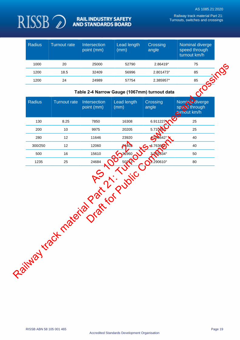
Radius Turnout rate Intersection point (mm)
Lead length (mm)
Crossing angle
Nominal diverge speed through turnout km/h
1000 20 25000 52790 2.86419° 75
1200 18.5 32409 56996 2.801473° 85
1200 24 24989 57754 2.385957° 85
Table 2-4 Narrow Gauge (1067mm) turnout data
Radius
Turnout rate Intersection point (mm)
Lead length (mm)
Crossing angle
Nominal diverge speed through turnout km/h
130 8.25 7850 16308 6.911227° 25
200 10 9975 20205 5.710593° 25
280 12 11646 23920 4.763642° 40
300/250 12 12060 24402 4.763642° 40
500 16 15610 31960 3.576334° 50
1235 25 24684 50213 2.290610° 80
AS 1085
.21
Railway
track
mate
rial P
art 21
: Turn
outs,
switc
hes a
nd cr
ossin
gs
Draft fo
r Pub
lic Com
ment
AS 1085.21:2020
Railway track material Part 21: Turnouts, switches and crossings
RISSB ABN 58 105 001 465 Page 20 Accredited Standards Development Organisation
2.4 Secant
2.4.1 General
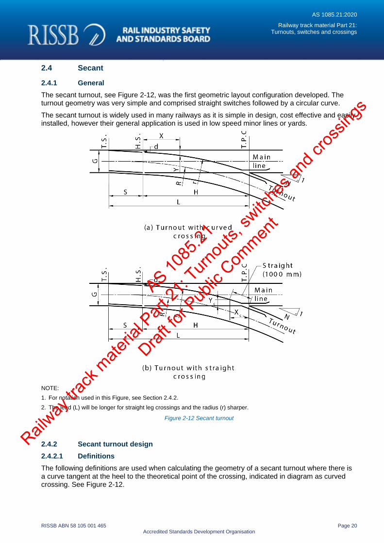
The secant turnout, see Figure 2-12, was the first geometric layout configuration developed. The turnout geometry was very simple and comprised straight switches followed by a circular curve.
The secant turnout is widely used in many railways as it is simple in design, cost effective and easily installed, however their general application is used in low speed minor lines or yards.
NOTE:
1. For notation used in this Figure, see Section 2.4.2.
2. The lead (L) will be longer for straight leg crossings and the radius (r) sharper.
Figure 2-12 Secant turnout
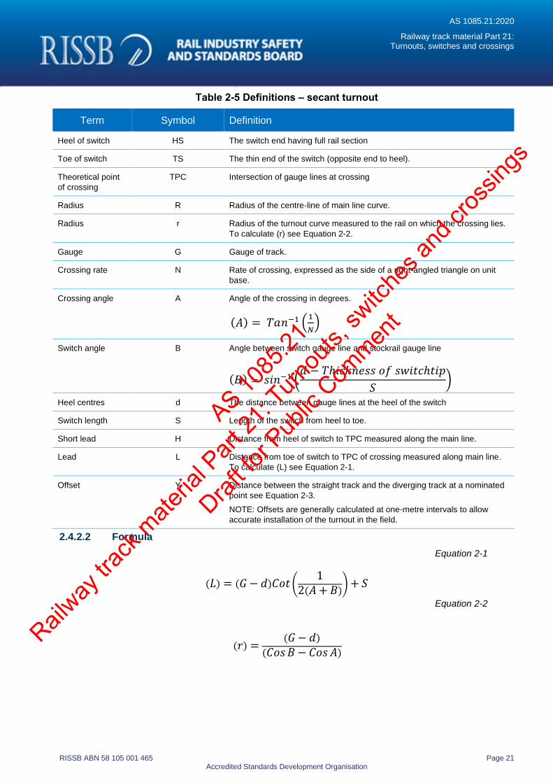
2.4.2 Secant turnout design
2.4.2.1 Definitions
The following definitions are used when calculating the geometry of a secant turnout where there is a curve tangent at the heel to the theoretical point of the crossing, indicated in diagram as curved crossing. See Figure 2-12.
AS 1085
.21
Railway
track
mate
rial P
art 21
: Turn
outs,
switc
hes a
nd cr
ossin
gs
Draft fo
r Pub
lic Com
ment
AS 1085.21:2020
Railway track material Part 21: Turnouts, switches and crossings
RISSB ABN 58 105 001 465 Page 21 Accredited Standards Development Organisation
Table 2-5 Definitions – secant turnout
Term Symbol Definition
Heel of switch HS The switch end having full rail section
Toe of switch TS The thin end of the switch (opposite end to heel).
Theoretical point
of crossing
TPC Intersection of gauge lines at crossing
Radius R Radius of the centre-line of main line curve.
Radius r Radius of the turnout curve measured to the rail on which the crossing lies.
To calculate (r) see Equation 2-2.
Gauge G Gauge of track.
Crossing rate N Rate of crossing, expressed as the side of a right-angled triangle on unit
base.
Crossing angle A Angle of the crossing in degrees.
(𝐴) = 𝑇𝑎𝑛−1 (1
𝑁)
Switch angle B Angle between switch gauge line and stockrail gauge line
(𝐵) = 𝑠𝑖𝑛−1 (𝑑 − 𝑇ℎ𝑖𝑐𝑘𝑛𝑒𝑠𝑠 𝑜𝑓 𝑠𝑤𝑖𝑡𝑐ℎ𝑡𝑖𝑝
𝑆)
Heel centres d The distance between gauge lines at the heel of the switch
Switch length S Length of the switch from heel to toe.
Short lead H Distance from heel of switch to TPC measured along the main line.
Lead L Distance from toe of switch to TPC of crossing measured along main line.
To calculate (L) see Equation 2-1.
Offset Y Distance between the straight track and the diverging track at a nominated
point see Equation 2-3.
NOTE: Offsets are generally calculated at one-metre intervals to allow
accurate installation of the turnout in the field.
2.4.2.2 Formula
Equation 2-1
(𝐿) = (𝐺 − 𝑑)𝐶𝑜𝑡 (1
2(𝐴 + 𝐵)) + 𝑆
Equation 2-2
(𝑟) =(𝐺 − 𝑑)
(𝐶𝑜𝑠 𝐵 − 𝐶𝑜𝑠 𝐴)
AS 1085
.21
Railway
track
mate
rial P
art 21
: Turn
outs,
switc
hes a
nd cr
ossin
gs
Draft fo
r Pub
lic Com
ment
AS 1085.21:2020
Railway track material Part 21: Turnouts, switches and crossings
RISSB ABN 58 105 001 465 Page 22 Accredited Standards Development Organisation
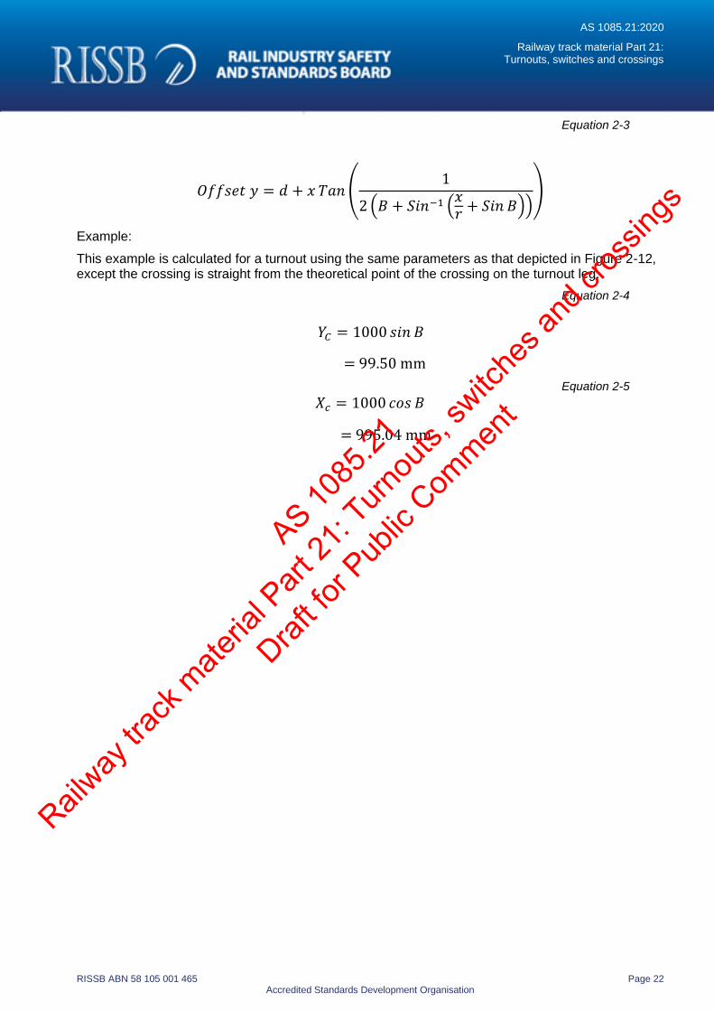
Equation 2-3
𝑂𝑓𝑓𝑠𝑒𝑡 𝑦 = 𝑑 + 𝑥 𝑇𝑎𝑛 (1
2 (𝐵 + 𝑆𝑖𝑛−1 (𝑥𝑟
+ 𝑆𝑖𝑛 𝐵)))
Example:
This example is calculated for a turnout using the same parameters as that depicted in Figure 2-12, except the crossing is straight from the theoretical point of the crossing on the turnout leg.
Equation 2-4
𝑌𝐶 = 1000 𝑠𝑖𝑛 𝐵
= 99.50 mm
Equation 2-5
𝑋𝑐 = 1000 𝑐𝑜𝑠 𝐵
= 995.04 mm
AS 1085
.21
Railway
track
mate
rial P
art 21
: Turn
outs,
switc
hes a
nd cr
ossin
gs
Draft fo
r Pub
lic Com
ment
AS 1085.21:2020
Railway track material Part 21: Turnouts, switches and crossings
RISSB ABN 58 105 001 465 Page 23 Accredited Standards Development Organisation
3 Interfaces
3.1 General
This section covers the interfaces that should be considered together with the geometric and loading factors when designing new turnouts, switches and crossings. These features are an integral part of the assembly and are essential in most situations.
Items to be taken into account include the following:
(a) Specific handing of the assembly.
(b) Location, handing and type of switch operating equipment.
(c) The positioning and type of insulated joints, where required (see seciton3.3).
(d) Compliance with structure outline.
3.2 Operating equipment
3.2.1 General
There is a wide variety of operating mechanisms available. Consideration should be given to interfacing with the turnout, switches and crossings. This section (3.2) covers components commonly used in the operation of switches and crossings.
3.2.2 Operating devices
Operating devices are designed to set the switch position. These devices can be manually operated, electric motor, hydraulic or electro-pneumatic or trailable.
Operating devices shall be designed to suit each specific application.
3.2.3 Operating rodding
Operating rodding is designed specifically to match the switch machine type selected. It is also used in situations where synchronized operation of the switches and crossing is required, e.g. swing nose crossing installations.
3.2.4 In-bearers
In-bearers allow for the rodding and other equipment to be incorporated within the bearer and permits tamping of switches without removing the operating equipment.
3.2.5 Switch locking
Switch locking is used to ensure the switches are locked and remain in that position while being normally traversed by a train.
3.2.6 Switch detection
Switch detection is used to detect and signal that the switch, or movable point crossing, is correctly positioned.
3.2.7 Condition monitoring
Sensors may be installed at certain locations to monitor the condition of the turnout.
AS 1085
.21
Railway
track
mate
rial P
art 21
: Turn
outs,
switc
hes a
nd cr
ossin
gs
Draft fo
r Pub
lic Com
ment
AS 1085.21:2020
Railway track material Part 21: Turnouts, switches and crossings
RISSB ABN 58 105 001 465 Page 24 Accredited Standards Development Organisation
3.3 Insulation
3.3.1 General
Where assemblies are to be installed in track circuited territory, track insulation is essential. Generally, all components, including fastenings, rodding and bearers require insulation to ensure electrical separation between running rails.
3.3.2 Insulated joints
For the conditions described above, insulated joints will also be required and the positioning within the layout/assembly will be critical to the operation of the signalling system. (Refer AS 1085.12.)
3.4 Installation
The proposed installation methodology should be considered in determining design, manufacturing and delivery of turnouts, switches and crossings to the site.
This can influence how the assembly is delivered to site and could also help to mitigate against damage that could occur during the installation process.
3.5 Track and structure interfaces
The final position in which the turnout will be located should be detailed including:
(a) other trackwork and structures which may encroach on the turnout placement;
(b) structure and gauge clearances;
(c) interface with other structures (i.e. platforms, tunnels, bridges, level and pedestrian crossings);
(d) interface with existing/adjacent trackwork; and
(e) catchpoints, run-off zones.
AS 1085
.21
Railway
track
mate
rial P
art 21
: Turn
outs,
switc
hes a
nd cr
ossin
gs
Draft fo
r Pub
lic Com
ment
AS 1085.21:2020
Railway track material Part 21: Turnouts, switches and crossings
RISSB ABN 58 105 001 465 Page 25 Accredited Standards Development Organisation
4 Manufacture
4.1 Materials, tests and standards
All the materials and processes supplied by the manufacturer shall, unless otherwise specified, conform to the requirements and test methods of the relevant current Australian Standards or other applicable recognized standards.
The purchaser may approve the use of a Standard other than an Australian Standard.
4.2 Rails, fishplates and sleeper plates
4.2.1 Rail
New rail shall comply with AS 1085.1 or other standard approved by the purchaser.
The use of head hardened rail shall be specified by the purchaser. Where a head hardened section is available for a particular rail size its use is recommended.
The straightness tolerance shall conform to the rail straightness for un-machined surfaces in accordance with AS 1085.1. In addition, the straightness shall not vary by more than 1mm over a length of 2 m.
New or part worn rail may be used for turnouts, switches and crossings manufacture. Part worn rail shall only be used with approval of the purchaser. The rail should:
(a) be free from surface defects greater than 1 mm deep;
(b) be straight, with a maximum allowable deviation of 3 mm over any 3 m length;
(c) have gauge faces that are smooth and free of metal flow;
(d) not have excessive top wear and side wear; top wear not to exceed 3 mm and side wear not to exceed 5mm.
Flame cutting of rails may also be permitted for ease of handling purposes. After flame cutting, the rails should be saw cut a minimum distance of 150mm from the flame cut edge.
Any reduction from the rolled section shall be by machining. The surface roughness value of machined or planed surfaces shall be better than 12.5 m.
4.2.2 Fishplates
Fishplates shall comply with AS 1085.2 or other standard approved by the purchaser. Flame cutting of holes in rails and fishplates is not permitted.
4.2.3 Sleeper plates
Cast reforged or fabricated steel plates may be used as an alternative to the standard rolled sleeper plates specified as AS 1085.3 or other standard approved by the purchaser.
Cast iron plates shall be made from AS 1831 minimum Grade 500-7 ductile iron or equivalent material.
4.3 Castings
All castings shall be:
(a) clean and smooth on the surface;
(b) free from surface defects;
AS 1085
.21
Railway
track
mate
rial P
art 21
: Turn
outs,
switc
hes a
nd cr
ossin
gs
Draft fo
r Pub
lic Com
ment
AS 1085.21:2020
Railway track material Part 21: Turnouts, switches and crossings
RISSB ABN 58 105 001 465 Page 26 Accredited Standards Development Organisation
(c) compatible with interfacing rail components;
(d) dimensions shown on the drawings;
(e) neatly dressed and cleaned;
(f) machined to accurately fit the rails.
Machined steel shall be smooth on the surface and sharp to the form and dimensions shown on the drawings.
All blocks shall be machined to accurately fit the rails.
4.4 Steel and iron castings
All steel and iron castings shall comply with the following standards:
(a) AS 1830 for cast iron.
(b) AS 1831 for ductile iron.
(c) AS 2074 for cast steel.
(d) Other equivalent standard approved by the rail infrastructure manager.
4.5 Manganese steel castings
4.5.1 General
All manganese steel castings shall comply with section 4.3.
Castings shall be manufactured so as to conform to the tolerances listed in Table 4-3.
Manganese steel castings, include:
(a) rail-bound manganese (RBM) crossing inserts;
(b) solid cast crossings;
(c) manganese steel switch tips; and
(d) any special component part used for turnouts, switches and crossings.
4.5.2 Material
Cast manganese steel shall be in accordance with AS 2074 minimum Grade H1A.
4.5.3 Heat treatment
Heat treatment shall be in accordance with AS 2074 minimum Grade H1A.
4.5.4 Machining allowance
Machining allowance may be specified, this is designed to remove surface defects from the critical regions of the casting and to reduce the amount of weld repairs performed. The machining allowance shall be removed by a metal cutting process.
4.5.5 Surface hardening
Unless indicated otherwise manganese steel crossings shall be explosively hardened to have hardness within the range 350 to 415 HBW, on all top surfaces and 20 mm down the flangeways.
Hardness testing shall be in accordance with AS 1816. Castings which fail to meet the hardness specifications may be accepted only where agreed by the purchaser.
AS 1085
.21
Railway
track
mate
rial P
art 21
: Turn
outs,
switc
hes a
nd cr
ossin
gs
Draft fo
r Pub
lic Com
ment
AS 1085.21:2020
Railway track material Part 21: Turnouts, switches and crossings
RISSB ABN 58 105 001 465 Page 27 Accredited Standards Development Organisation
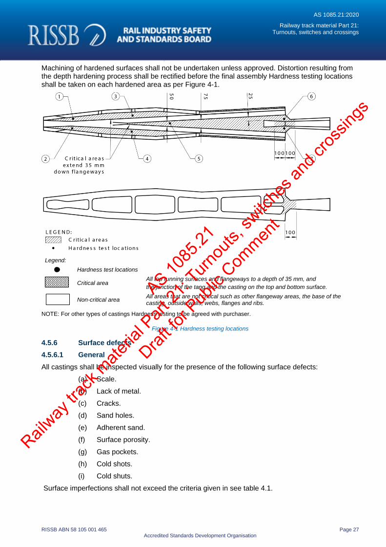
Machining of hardened surfaces shall not be undertaken unless approved. Distortion resulting from the depth hardening process shall be rectified before the final assembly Hardness testing locations shall be taken on each hardened area as per Figure 4-1.
Legend:
Hardness test locations
Critical area
All top running surfaces and flangeways to a depth of 35 mm, and
the junction of the tang and the casting on the top and bottom surface.
Non-critical area
All areas that are not critical such as other flangeway areas, the base of the casting, outside walls, webs, flanges and ribs.
NOTE: For other types of castings Hardness testing to be agreed with purchaser.
Figure 4-1 Hardness testing locations
4.5.6 Surface defects
4.5.6.1 General
All castings shall be inspected visually for the presence of the following surface defects:
(a) Scale.
(b) Lack of metal.
(c) Cracks.
(d) Sand holes.
(e) Adherent sand.
(f) Surface porosity.
(g) Gas pockets.
(h) Cold shots.
(i) Cold shuts.
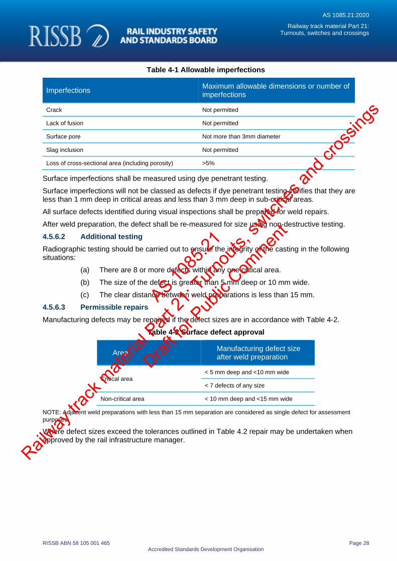
Surface imperfections shall not exceed the criteria given in see table 4.1.
AS 1085
.21
Railway
track
mate
rial P
art 21
: Turn
outs,
switc
hes a
nd cr
ossin
gs
Draft fo
r Pub
lic Com
ment
AS 1085.21:2020
Railway track material Part 21: Turnouts, switches and crossings
RISSB ABN 58 105 001 465 Page 28 Accredited Standards Development Organisation
Table 4-1 Allowable imperfections
Imperfections Maximum allowable dimensions or number of imperfections
Crack Not permitted
Lack of fusion Not permitted
Surface pore Not more than 3mm diameter
Slag inclusion Not permitted
Loss of cross-sectional area (including porosity) >5%
Surface imperfections shall be measured using dye penetrant testing.
Surface imperfections will not be classed as defects if dye penetrant testing verifies that they are less than 1 mm deep in critical areas and less than 3 mm deep in sub-critical areas.
All surface defects identified during visual inspections shall be prepared for weld repairs.
After weld preparation, the defect shall be re-measured for size using non-destructive testing.
4.5.6.2 Additional testing
Radiographic testing should be carried out to ensure the integrity of the casting in the following situations:
(a) There are 8 or more defects within any one critical area.
(b) The size of the defect is greater than 5 mm deep or 10 mm wide.
(c) The clear distance between weld preparations is less than 15 mm.
4.5.6.3 Permissible repairs
Manufacturing defects may be repaired if the defect sizes are in accordance with Table 4-2.
Table 4-2 Surface defect approval
Area Manufacturing defect size after weld preparation
Critical area < 5 mm deep and <10 mm wide
< 7 defects of any size
Non-critical area < 10 mm deep and <15 mm wide
NOTE: Adjacent weld preparations with less than 15 mm separation are considered as single defect for assessment
purposes.
Where defect sizes exceed the tolerances outlined in Table 4.2 repair may be undertaken when approved by the rail infrastructure manager.
AS 1085
.21
Railway
track
mate
rial P
art 21
: Turn
outs,
switc
hes a
nd cr
ossin
gs
Draft fo
r Pub
lic Com
ment
AS 1085.21:2020
Railway track material Part 21: Turnouts, switches and crossings
RISSB ABN 58 105 001 465 Page 29 Accredited Standards Development Organisation
4.5.7 Repairing defects
4.5.7.1 General
Defects shall not be repaired by peening, plugging or impregnating.
Weld repairs shall not be performed on a casting following the explosive hardening process. If any defect is found in a region that has been explosively hardened, the casting shall not be accepted.
Casting defects in new manganese steel inserts that have not been explosively hardened may be repaired by welding.
The complete removal of defects shall be verified by dye penetrant testing.
Welding repairs shall be performed in accordance AS 1988.
All weld repairs shall be performed in accordance with a qualified weld procedure endorsed by the rail infrastructure manager.
When weld repair is undertaken, all preparatory work, welding and non-destructive testing shall be undertaken by a competent person experienced in the qualified weld procedure.
4.5.7.2 Qualifying a weld procedure
A procedure will be deemed qualified when a test sample is welded under similar conditions to that encountered in production and destructively tested by preparing two macro-specimens in accordance with AS 2205.1. The two macro-specimens should not be opposing surfaces of the same cut.
Both the weld and heat affected zone (HAZ) shall be examined. The qualified welding procedure must contain all of the information necessary for the welder to perform the repair and may take the form of a work instruction.
The test sample shall consist of manganese steel complying with this specification of final dimensions not less than 25 mm × 60 mm × 200 mm. Surface decarburization shall be removed from the surface to be welded. Four layers of weld metal shall be deposited to within 5 mm of all edges. The heat input shall not exceed 1.0 kJ/mm. The interpass temperature shall not exceed 260°C. The test piece can be tack welded to a backing plate to prevent distortion and shall be welded in the flat position. Unless otherwise approve by the rail infrastructure manager, electrodes shall be equivalent to AWS A5.13 EFeMn-A/B/C/D/E or AWS A5.21 ERFEMn-C/F/G/H.
Welders shall be qualified by welding the same test sample as detailed above using a qualified welding procedure and tested in accordance with the above.
4.5.7.3 Explosive hardening
Explosive hardening, if required by the purchaser, shall be carried out following weld repair and reheat treatment.
Following the explosive hardening, hardness testing in line with section 4.5.5 shall be carried out at the locations shown in Figure 4.1.
Manufacturers shall maintain suitable quality records of the hardness test report.
4.5.7.4 Straightening of castings
Following explosive hardening, the casting shall be straightened and machined in non-critical areas so as to conform to the tolerances listed in tolerance Table 4-3.
4.5.7.5 Epoxy gluing of RBM castings
All blocks and RBM crossings may be epoxy glued using an air curing epoxy. Surface preparation should be in accordance with the recommendations of the epoxy glue manufacturer. As a minimum, surface preparation shall include sand blasting or an equivalent surface preparation and degreasing.
AS 1085
.21
Railway
track
mate
rial P
art 21
: Turn
outs,
switc
hes a
nd cr
ossin
gs
Draft fo
r Pub
lic Com
ment
AS 1085.21:2020
Railway track material Part 21: Turnouts, switches and crossings
RISSB ABN 58 105 001 465 Page 30 Accredited Standards Development Organisation
The fitting surfaces shall comply with section 4.1 and in no circumstances shall epoxy be used in lieu of a proper fit.
4.5.8 Theoretical point
The theoretical point shall be marked on the cast crossings, after final machining and assembly as appropriate.
4.5.9 Identification
All crossings shall be designated with an embossed stamp or glued on plate on the body of the casting. The marking shall be in a visible place that will not undergo any wear. The marking should include the following details:
(a) Name or symbol of manufacturer.
(b) Manufacturer’s serial/work order number.
(c) Year of manufacture.
(d) Angle of crossing.
(e) Size of rail.
(f) Heat number.
4.5.10 Weld maps
A weld map shall be prepared for all castings produced.
Weld maps shall show the location of each weld. If the casting has no defects the weld map is to be clearly marked with ‘No defects’.
Weld maps shall also include:
(a) the heat number,
(b) manufacturer’s name, and
(c) crossing rate.
4.6 Fastening
4.6.1 Bolts
Fishbolts shall comply with Australian Standard for fishbolts and nuts, AS 1085.4.
High strength (HS) steel bolts and associated nuts and washers shall comply with AS/NZS 1252 or equivalent grade.
All bolts shall be of the forms and sizes nominated in the design and of a length to provide 3 mm minimum to 12 mm maximum projection of the end of the bolt beyond the nut when finally screwed into position.
The head of all bolts shall be formed by forging.
Tapered washers shall be used with bolts when the angle between the head of the fastener and the rail exceeds 3 degrees. Tapered washers shall be manufactured from either cast steel, AS 2074 Grade C6, or steel in accordance with AS/NZS 3679 minimum grade 250.
4.6.2 Swaged fastenings
Swaged fastenings shall be used with flanged or non-flanged collars.
Non-flanged collars may be used in conjunction with either a flat or tapered hardened washer.
AS 1085
.21
Railway
track
mate
rial P
art 21
: Turn
outs,
switc
hes a
nd cr
ossin
gs
Draft fo
r Pub
lic Com
ment
AS 1085.21:2020
Railway track material Part 21: Turnouts, switches and crossings
RISSB ABN 58 105 001 465 Page 31 Accredited Standards Development Organisation
The first washer under the head of any swaged fastener shall have clearance for the head to shank radius.
Tapered washers shall be used with swaged fasteners when the angle between the head of the fastener and the rail exceeds 3 degrees. Tapered washers shall be manufactured from either cast steel, AS 2074 Grade C6, or steel in accordance with AS/NZS 3679 minimum grade 250.
Flat hardened washers shall be used to pack the swaged fasteners to obtain the correct grip length and shall be equally distributed under the head and collar.
The maximum clearance between the inside diameter of the washer and pin shall be 3mm.
Up to a maximum total of four washers shall be used to provide grip length.
The total number of washer combinations shall consist of either:
(a) four 4 mm washers, or
(b) two 4 mm washers and two 10 mm washers.
Washers shall be equally distributed under the head and collar. The number of washers should be kept to a minimum.
4.6.3 Retaining compound
Where high strength steel bolts are approved for use in crossings, a high strength anaerobic retaining compound shall be applied to the threads of the bolts and their nuts during the final assembly.
The threads shall be clean and dry and any rust, grease, oil, etc. shall be removed from the threads by a wire brush as far as possible. Solvents such as petrol and kerosene shall not be used to clean oil or grease.
4.7 Flame cutting
Rails shall not be flame cut.
4.8 Welding
Unless approved by the purchaser, welding shall only be permitted where shown on the drawings and shall be in accordance with AS/NZS 1554.1.
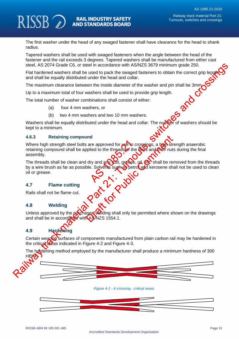
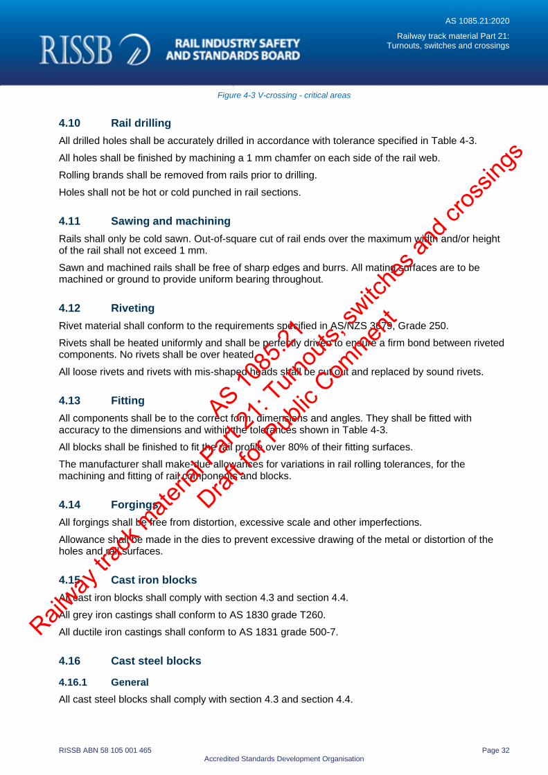
4.9 Hardening
Certain wearing surfaces of components manufactured from plain carbon rail may be hardened in the critical areas indicated in Figure 4-2 and Figure 4-3.
The hardening method employed by the manufacturer shall produce a minimum hardness of 300 HBW.
Figure 4-2 - K-crossing - critical areas
AS 1085
.21
Railway
track
mate
rial P
art 21
: Turn
outs,
switc
hes a
nd cr
ossin
gs
Draft fo
r Pub
lic Com
ment
AS 1085.21:2020
Railway track material Part 21: Turnouts, switches and crossings
RISSB ABN 58 105 001 465 Page 32 Accredited Standards Development Organisation
Figure 4-3 V-crossing - critical areas
4.10 Rail drilling
All drilled holes shall be accurately drilled in accordance with tolerance specified in Table 4-3.
All holes shall be finished by machining a 1 mm chamfer on each side of the rail web.
Rolling brands shall be removed from rails prior to drilling.
Holes shall not be hot or cold punched in rail sections.
4.11 Sawing and machining
Rails shall only be cold sawn. Out-of-square cut of rail ends over the maximum width and/or height of the rail shall not exceed 1 mm.
Sawn and machined rails shall be free of sharp edges and burrs. All mating surfaces are to be machined or ground to provide uniform bearing throughout.
4.12 Riveting
Rivet material shall conform to the requirements specified in AS/NZS 3679, Grade 250.
Rivets shall be heated uniformly and shall be perfectly driven to ensure a firm bond between riveted components. No rivets shall be over heated.
All loose rivets and rivets with mis-shaped heads shall be cut out and replaced by sound rivets.
4.13 Fitting
All components shall be to the correct form, dimensions and angles. They shall be fitted with accuracy to the dimensions and within the tolerances shown in Table 4-3.
All blocks shall be finished to fit the rail profile over 80% of their fitting surfaces.
The manufacturer shall make-due allowances for variations in rail rolling tolerances, for the machining and fitting of rail components and blocks.
4.14 Forgings
All forgings shall be free from distortion, excessive scale and other imperfections.
Allowance shall be made in the dies to prevent excessive drawing of the metal or distortion of the holes and rail surfaces.
4.15 Cast iron blocks
All cast iron blocks shall comply with section 4.3 and section 4.4.
All grey iron castings shall conform to AS 1830 grade T260.
All ductile iron castings shall conform to AS 1831 grade 500-7.
4.16 Cast steel blocks
4.16.1 General
All cast steel blocks shall comply with section 4.3 and section 4.4.
AS 1085
.21
Railway
track
mate
rial P
art 21
: Turn
outs,
switc
hes a
nd cr
ossin
gs
Draft fo
r Pub
lic Com
ment
AS 1085.21:2020
Railway track material Part 21: Turnouts, switches and crossings
RISSB ABN 58 105 001 465 Page 33 Accredited Standards Development Organisation
4.16.2 Steel blocks, and steel packing blocks
Steel filler blocks, steel distance blocks and steel packing blocks may be manufactured from one of the following:
(a) Cast steel, the class and quality of which shall comply AS 2074 grade L1.
(b) Machined from AS/NZS 3679 minimum grade 250.
4.17 Special heel bolt ferrules
Special heel bolt ferrules shall be machined from AS 1442 grades S1040 or S1045 steel bar, case hardened and tempered to 480 HBW.
4.18 Nylon bushes
Bushes shall be injection moulded from type 11 nylon impregnated with graphite or molybdenum disulphide or an approved equivalent.
4.19 Epoxy gluing of crossings
Epoxy gluing shall not be used in lieu of a proper fit.
When specified, blocks and rail mating surfaces used in turnouts, switches and crossings shall be epoxy glued using air curing epoxy or purchaser approved equivalent.
Surface preparation should be in accordance with the recommendations of the epoxy glue manufacturer.
As a minimum, surface preparation shall include sand blasting or an equivalent surface preparation and degreasing.
4.20 Switch assembly
Switch assemblies comprise of a switch, stockrail and associated components.
Switch and stockrails shall be machined accurately to the dimensions and sections shown on the manufacturing drawings.
Distortion of parts caused by machining or other operations shall be corrected before the switch and stockrail is assembled.
All arises and sharp edges on switches created by the machining process shall be ground off.
Switch assemblies for the turnout shall have the appropriate set in the stockrails for the nominated turnout type.
The assembly shall have plates, switch stops, heel blocks or anti-creep device attached.
Each switch assembly shall be fitted together as a complete set on a strong level platform, or other surface, and measured for compliance to the relevant drawings.
All sliding surfaces of switch chair plates shall be coated with an approved lubricant or provided with an engineered surface which does not require the use of lubricant.
4.21 Crossing assembly
A crossing assembly may be a solid casting or be manufactured from rail, manganese steel or other approved material.
AS 1085
.21
Railway
track
mate
rial P
art 21
: Turn
outs,
switc
hes a
nd cr
ossin
gs
Draft fo
r Pub
lic Com
ment
AS 1085.21:2020
Railway track material Part 21: Turnouts, switches and crossings
RISSB ABN 58 105 001 465 Page 34 Accredited Standards Development Organisation
Crossing components shall be machined accurately to the dimensions and sections shown on the manufacturing drawings.
Distortion of parts caused by machining or other operations shall be corrected prior to assembly of crossings.
All arises and sharp edges on crossings created by the machining process shall be ground off.
All rails for the crossings shall have the appropriate sets and curves to meet required angles and radii. Consideration should be given during pressing operations to ensure excessive stress in the rail does not occur.
The assembly shall have plates, blocks and stops attached.
Each crossing assembly shall be fitted together on a strong level platform, or other surface, and measured for compliance to the relevant drawings.
All sliding surfaces shall be coated with an approved lubricant or provided with an engineered surface which does not require the use of lubricant.
Swing nose crossing assemblies may be provided with a sliding joint with an approved lubricant.
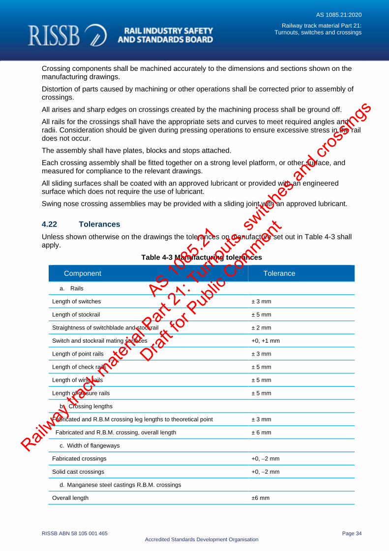
4.22 Tolerances
Unless shown otherwise on the drawings the tolerances on manufacture set out in Table 4-3 shall apply.
Table 4-3 Manufacturing tolerances
Component Tolerance
a. Rails
Length of switches ± 3 mm
Length of stockrail ± 5 mm
Straightness of switchblade and stockrail ± 2 mm
Switch and stockrail mating surfaces +0, +1 mm
Length of point rails ± 3 mm
Length of check rails ± 5 mm
Length of wing rails ± 5 mm
Length of closure rails ± 5 mm
b. Crossing lengths
Fabricated and R.B.M crossing leg lengths to theoretical point ± 3 mm
Fabricated and R.B.M. crossing, overall length ± 6 mm
c. Width of flangeways
Fabricated crossings +0, −2 mm
Solid cast crossings +0, −2 mm
d. Manganese steel castings R.B.M. crossings
Overall length ±6 mm
AS 1085
.21
Railway
track
mate
rial P
art 21
: Turn
outs,
switc
hes a
nd cr
ossin
gs
Draft fo
r Pub
lic Com
ment
AS 1085.21:2020
Railway track material Part 21: Turnouts, switches and crossings
RISSB ABN 58 105 001 465 Page 35 Accredited Standards Development Organisation
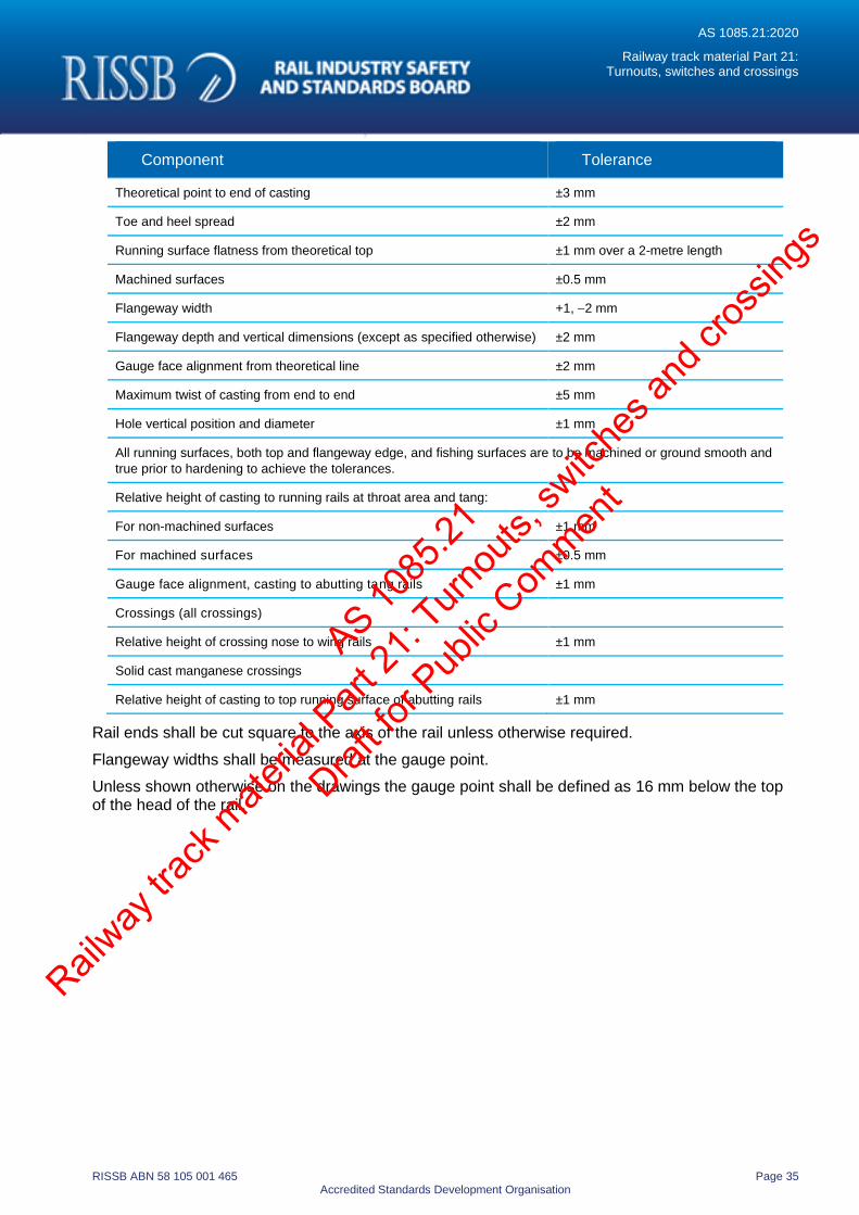
Component Tolerance
Theoretical point to end of casting ±3 mm
Toe and heel spread ±2 mm
Running surface flatness from theoretical top ±1 mm over a 2-metre length
Machined surfaces ±0.5 mm
Flangeway width +1, −2 mm
Flangeway depth and vertical dimensions (except as specified otherwise) ±2 mm
Gauge face alignment from theoretical line ±2 mm
Maximum twist of casting from end to end ±5 mm
Hole vertical position and diameter ±1 mm
All running surfaces, both top and flangeway edge, and fishing surfaces are to be machined or ground smooth and
true prior to hardening to achieve the tolerances.
Relative height of casting to running rails at throat area and tang:
For non-machined surfaces ±1 mm
For machined surfaces ±0.5 mm
Gauge face alignment, casting to abutting tang rails ±1 mm
Crossings (all crossings)
Relative height of crossing nose to wing rails ±1 mm
Solid cast manganese crossings
Relative height of casting to top running surface of abutting rails ±1 mm
Rail ends shall be cut square to the axis of the rail unless otherwise required.
Flangeway widths shall be measured at the gauge point.
Unless shown otherwise on the drawings the gauge point shall be defined as 16 mm below the top of the head of the rail.
AS 1085
.21
Railway
track
mate
rial P
art 21
: Turn
outs,
switc
hes a
nd cr
ossin
gs
Draft fo
r Pub
lic Com
ment
AS 1085.21:2020
Railway track material Part 21: Turnouts, switches and
crossings
RISSB ABN 58 105 001 465 Page 36 Accredited Standards Development Organisation
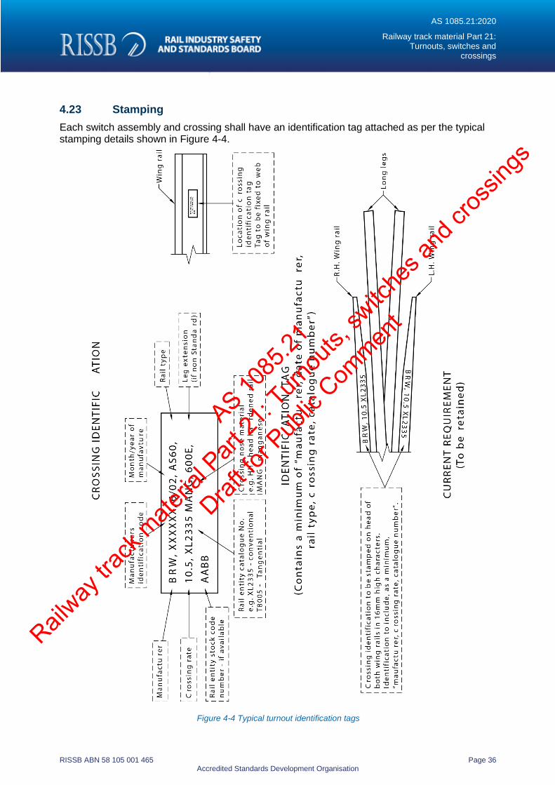
4.23 Stamping
Each switch assembly and crossing shall have an identification tag attached as per the typical stamping details shown in Figure 4-4.
Figure 4-4 Typical turnout identification tags
AS 1085
.21
Railway
track
mate
rial P
art 21
: Turn
outs,
switc
hes a
nd cr
ossin
gs
Draft fo
r Pub
lic Com
ment
AS 1085.21:2020
Railway track material Part 21: Turnouts, switches and
crossings
RISSB ABN 58 105 001 465 Page 37 Accredited Standards Development Organisation
4.24 Match marking
Each turnout shall be match marked to facilitate re-assembly in the field. The match marking may be either colour coding, lettering or numbering.
4.25 Painting and coating
If requested by the purchaser all components except bolts, pins and sliding surfaces of plates may be coated with one coat of an approved ‘environmentally friendly’ protective coating.
Prior to dispatch the sliding surfaces of plates shall be coated with an approved plate lubricant. The coating may be applied by brushing, spraying or dipping.
All bolts and pins may be dipped in an approved protective coating.
Surfaces shall not be painted or oiled before final inspection. All loose rust and mill scale shall be removed before painting.
4.26 Final assembly and inspection
The purchaser may nominate the whole item, or any portion thereof, to be completely assembled prior to delivery. The assembly shall comply with all the specifications in Section 3 of this Standard.
The purchaser may require an inspection of the track assemblies and components at their discretion.
If an inspection is required, the sub-contractor shall demonstrate compliance to the purchaser’s specifications through the use of an approved quality assurance plan or system.
4.27 Preparation for dispatch
All components shall be prepared for dispatch into sub-assemblies, as individual rails or packed components.
Sub-assemblies (e.g. switches) shall be securely held together with an approved method and stiffened if necessary, so no damage can occur during transport or handling.
Individual rails (e.g. check rails/closure rails) shall be securely held together with an approved method or loaded individually, so no damage can occur during transport or handling.
All packaged components, including bundles or bags of items, shall be packed into suitable crates or boxes and securely bound so no damage can occur during transport or handling.
All components, individual rails or packaged items shall be clearly labelled for identification in an approved manner so to be easily distinguished by the purchaser.
AS 1085
.21
Railway
track
mate
rial P
art 21
: Turn
outs,
switc
hes a
nd cr
ossin
gs
Draft fo
r Pub
lic Com
ment
AS 1085.21:2020
Railway track material Part 21: Turnouts, switches and
crossings
RISSB ABN 58 105 001 465 Page 38 Accredited Standards Development Organisation
5 Product acceptance
5.1 General
This section covers product acceptance of new and existing turnouts, switches and crossings design and manufacture.
5.2 Type approval
The type approval process should typically include sections on determination of need, safety, performance, reliability, suitability, previous use of similar designs on other systems, maintainability and cost benefits. Networks and asset owners may have varying type approval process, which should be applied when introducing a new product into a system.
5.3 Certificate of compliance
Manufacturers shall provide a certificate of compliance that details the conformance with this Standard and any further specific requirements when requested.
5.4 Trial assembly
Trial assemblies may be requested by the purchaser for initial proving and validation of product.
5.5 Assembly maintenance manuals and drawings
5.5.1 Assembly
The Manufacturer shall provide instructions for the assembly of turnouts, switches and crossing when requested by the purchaser.
5.5.2 Maintenance
Manufacturers shall provide recommendations for the maintenance of turnouts, switches and crossings when requested by the purchaser.
5.5.3 Manuals and drawings
Manufacturers shall provide assembly manuals particularly where new equipment or methods are introduced. The manual may include recommended lifting points, maximum length and mass of individual components.
AS 1085
.21
Railway
track
mate
rial P
art 21
: Turn
outs,
switc
hes a
nd cr
ossin
gs
Draft fo
r Pub
lic Com
ment
AS 1085.21:2020
Railway track material Part 21: Turnouts, switches and
crossings
RISSB ABN 58 105 001 465 Page 39 Accredited Standards Development Organisation
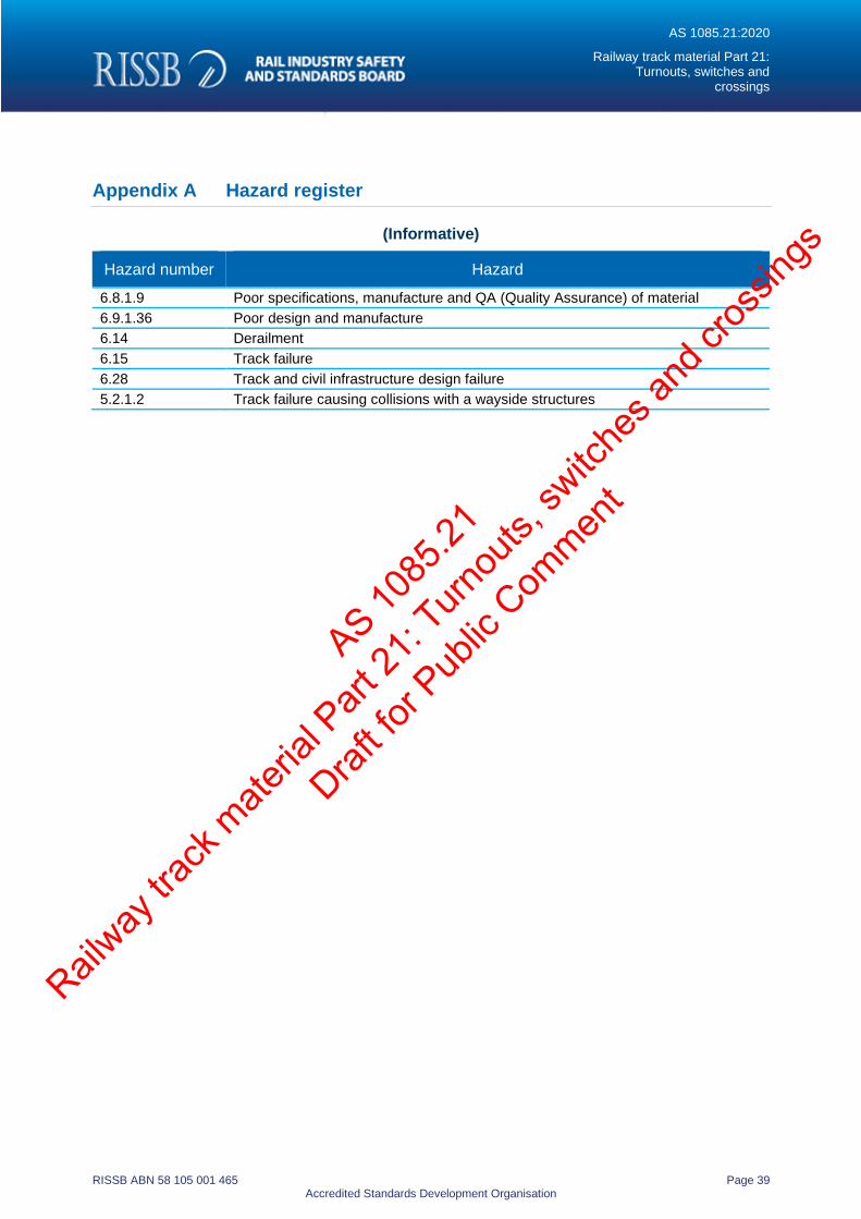
Appendix A Hazard register
(Informative)
Hazard number Hazard
6.8.1.9 Poor specifications, manufacture and QA (Quality Assurance) of material
6.9.1.36 Poor design and manufacture
6.14 Derailment
6.15 Track failure
6.28 Track and civil infrastructure design failure
5.2.1.2 Track failure causing collisions with a wayside structures
AS 1085
.21
Railway
track
mate
rial P
art 21
: Turn
outs,
switc
hes a
nd cr
ossin
gs
Draft fo
r Pub
lic Com
ment
AS 1085.21:2020
Railway track material Part 21: Turnouts, switches and
crossings
RISSB ABN 58 105 001 465 Page 40 Accredited Standards Development Organisation
Appendix B Terminology and drawings
(Informative)
B.1 General
This appendix provides additional terms, definitions and drawings used in relation to turnouts, switches and crossings.
B.2 Bearer
A type of sleeper used under turnouts and special trackwork. Bearers are generally larger in dimension than standard sleepers to provide support for both tracks as well as the increased loading experienced under such track structures. Generally manufactured from either steel, concrete or timber.
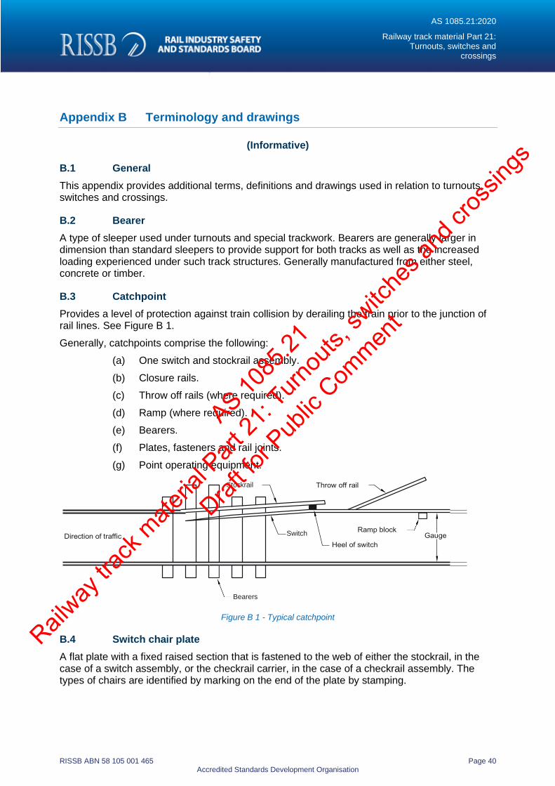
B.3 Catchpoint
Provides a level of protection against train collision by derailing the train prior to the junction of rail lines. See Figure B 1.
Generally, catchpoints comprise the following:
(a) One switch and stockrail assembly.
(b) Closure rails.
(c) Throw off rails (where required).
(d) Ramp (where required).
(e) Bearers.
(f) Plates, fasteners and rail joints.
(g) Point operating equipment.
Figure B 1 - Typical catchpoint
B.4 Switch chair plate
A flat plate with a fixed raised section that is fastened to the web of either the stockrail, in the case of a switch assembly, or the checkrail carrier, in the case of a checkrail assembly. The types of chairs are identified by marking on the end of the plate by stamping.
Stockrail
Switch
Bearers
AS 1085
.21
Railway
track
mate
rial P
art 21
: Turn
outs,
switc
hes a
nd cr
ossin
gs
Draft fo
r Pub
lic Com
ment
AS 1085.21:2020
Railway track material Part 21: Turnouts, switches and
crossings
RISSB ABN 58 105 001 465 Page 41 Accredited Standards Development Organisation
B.5 Checkrail
A steel section (can be manufactured from rail) placed inside the running rail which comes into contact with the back of the wheel flange, along the checking face. It is used to provide steering of the wheel set, such that the crossing nose or switch point is not contacted and is protected by the opposite wheel.
A checkrail can be raised above the level of the running rail (i.e. the top of the checkrail is above the running rail).
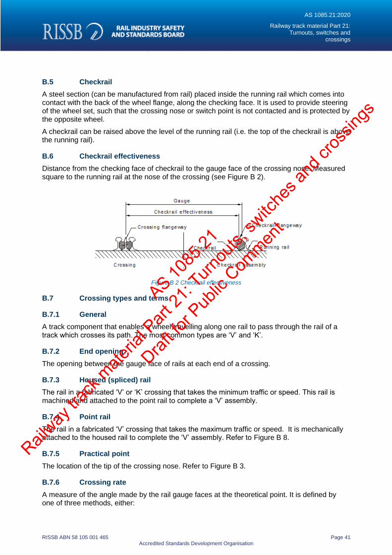
B.6 Checkrail effectiveness
Distance from the checking face of checkrail to the gauge face of the crossing nose. Measured square to the running rail at the nose of the crossing (see Figure B 2).
Figure B 2 Checkrail effectiveness
B.7 Crossing types and terms
B.7.1 General
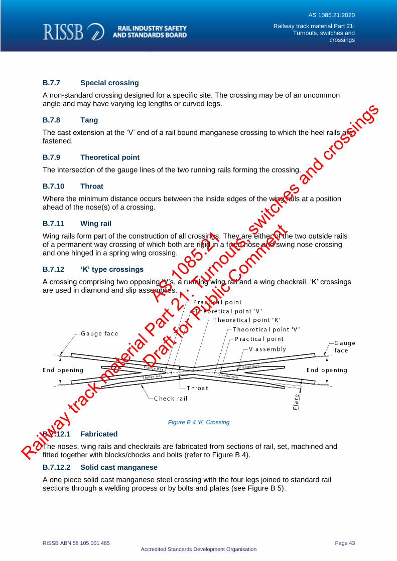
A track component that enables a wheel travelling along one rail to pass through the rail of a track which crosses its path. The most common types are ‘V’ and ‘K’.
B.7.2 End opening
The opening between the gauge face of rails at each end of a crossing.
B.7.3 Housed (spliced) rail
The rail in a fabricated ‘V’ or ‘K’ crossing that takes the minimum traffic or speed. This rail is machined and attached to the point rail to complete a ‘V’ assembly.
B.7.4 Point rail
The rail in a fabricated ‘V’ crossing that takes the maximum traffic or speed. It is mechanically attached to the housed rail to complete the ‘V’ assembly. Refer to Figure B 8.
B.7.5 Practical point
The location of the tip of the crossing nose. Refer to Figure B 3.
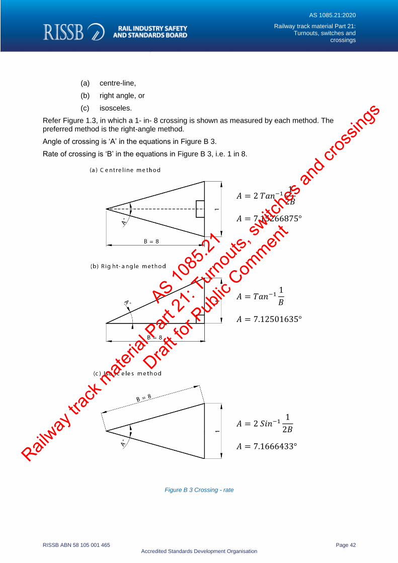
B.7.6 Crossing rate
A measure of the angle made by the rail gauge faces at the theoretical point. It is defined by one of three methods, either:
AS 1085
.21
Railway
track
mate
rial P
art 21
: Turn
outs,
switc
hes a
nd cr
ossin
gs
Draft fo
r Pub
lic Com
ment
AS 1085.21:2020
Railway track material Part 21: Turnouts, switches and
crossings
RISSB ABN 58 105 001 465 Page 42 Accredited Standards Development Organisation
(a) centre-line,
(b) right angle, or
(c) isosceles.
Refer Figure 1.3, in which a 1- in- 8 crossing is shown as measured by each method. The preferred method is the right-angle method.
Angle of crossing is ‘A’ in the equations in Figure B 3.
Rate of crossing is ‘B’ in the equations in Figure B 3, i.e. 1 in 8.
𝐴 = 2 𝑇𝑎𝑛−11
2𝐵
𝐴 = 7.15266875°
𝐴 = 𝑇𝑎𝑛−11
𝐵
𝐴 = 7.12501635°
𝐴 = 2 𝑆𝑖𝑛−11
2𝐵
𝐴 = 7.1666433°
Figure B 3 Crossing - rate
AS 1085
.21
Railway
track
mate
rial P
art 21
: Turn
outs,
switc
hes a
nd cr
ossin
gs
Draft fo
r Pub
lic Com
ment
AS 1085.21:2020
Railway track material Part 21: Turnouts, switches and
crossings
RISSB ABN 58 105 001 465 Page 43 Accredited Standards Development Organisation
B.7.7 Special crossing
A non-standard crossing designed for a specific site. The crossing may be of an uncommon angle and may have varying leg lengths or curved legs.
B.7.8 Tang
The cast extension at the ‘V’ end of a rail bound manganese crossing to which the heel rails are fastened.
B.7.9 Theoretical point
The intersection of the gauge lines of the two running rails forming the crossing.
B.7.10 Throat
Where the minimum distance occurs between the inside edges of the wing rails at a position ahead of the nose(s) of a crossing.
B.7.11 Wing rail
Wing rails form part of the construction of all crossings. They are either of the two outside rails of a permanent way crossing of which both are rigid in a fixed nose and swing nose crossing and one hinged in a spring wing crossing.
B.7.12 ‘K’ type crossings
A crossing comprising two opposing ‘V’s, a running wing rail and a wing checkrail. ‘K’ crossings are used in diamond and slip assemblies.
Figure B 4 ‘K’ Crossing
B.7.12.1 Fabricated
The noses, wing rails and checkrails are fabricated from sections of rail, set, machined and fitted together with blocks/chocks and bolts (refer to Figure B 4).
B.7.12.2 Solid cast manganese
A one piece solid cast manganese steel crossing with the four legs joined to standard rail sections through a welding process or by bolts and plates (see Figure B 5).
AS 1085
.21
Railway
track
mate
rial P
art 21
: Turn
outs,
switc
hes a
nd cr
ossin
gs
Draft fo
r Pub
lic Com
ment
AS 1085.21:2020
Railway track material Part 21: Turnouts, switches and
crossings
RISSB ABN 58 105 001 465 Page 44 Accredited Standards Development Organisation
Figure B 5 ‘K’ Crossing types – Solid cast manganese
AS 1085
.21
Railway
track
mate
rial P
art 21
: Turn
outs,
switc
hes a
nd cr
ossin
gs
Draft fo
r Pub
lic Com
ment
AS 1085.21:2020
Railway track material Part 21: Turnouts, switches and
crossings
RISSB ABN 58 105 001 465 Page 45 Accredited Standards Development Organisation
B.7.12.3 Switchable
The two opposing switches of the ‘K’ crossing that move to allow a continuous surface for the wheel to run through the crossing (see Figure B 6).
Figure B 6 ‘K’ crossing types – switchable
B.7.13 ‘V’ type crossings
A crossing comprising a ‘V’ and two wing rails fixed by blocks/chocks and bolting to a specified geometric configuration (See Figure B 7).
Figure B 7 ‘V’ crossing
B.7.13.1 Fabricated
A fabricated ‘V’ crossing comprises a ‘V’ which is manufactured from a point rail and a housed rail which are machined to match, assembled with two wing rails, fitted with spacer blocks and bolted or swage fastened together at the required angle (see Figure B 8).
The point rail may be right hand or left hand and is generally laid along the rail carrying the predominant traffic.
Figure B 8 ‘V’ crossing types - fabricated
Heel block Theoretical point Heel block
Switch throw Toe of switch
AS 1085
.21
Railway
track
mate
rial P
art 21
: Turn
outs,
switc
hes a
nd cr
ossin
gs
Draft fo
r Pub
lic Com
ment
AS 1085.21:2020
Railway track material Part 21: Turnouts, switches and
crossings
RISSB ABN 58 105 001 465 Page 46 Accredited Standards Development Organisation
B.7.13.2 Compound
A compound crossing comprises a single piece ‘V’ and two wing rails which form the front legs of the crossing. See Figure B 9.
The ‘V’ point is manufactured from a special material (e.g. cast manganese, billet steel or forged material) which is welded to rails to complete the ‘V’. This assembly in the wheel transfer area replaces the point/housed rails in a fabricated crossing. Spacer blocks may be epoxy-glued or welded to the ‘V’ and are fastened together using high-tensile bolts or high tensile swage fasteners.
Figure B 9 ‘V’ crossing types – compounds
5.5.3.1 Rail bound manganese
Rail-bound manganese (RBM) crossings are crossings which include two specially machined and set wing rails which form the front legs of the crossing and which then enclose the insert casting and provide guarding of the transfer from the casting to the heel rails. (see Figure B 10)
Additional spacer blocks are provided between the rails and insert to provide flangeway clearance and strength to the crossing assembly.
The insert, wing rails, heel rails and spacer blocks are usually set with an epoxy glue and secured with high tensile swage fasteners.
The manganese steel insert casting is usually machined and explosively hardened prior to its assembly into the crossing.
Figure B 10 ’V’ crossing types – rail bound manganese
AS 1085
.21
Railway
track
mate
rial P
art 21
: Turn
outs,
switc
hes a
nd cr
ossin
gs
Draft fo
r Pub
lic Com
ment
AS 1085.21:2020
Railway track material Part 21: Turnouts, switches and
crossings
RISSB ABN 58 105 001 465 Page 47 Accredited Standards Development Organisation
B.7.13.3 Solid cast manganese
Cast manganese steel monoblock crossings, or cast solid crossings are manufactured from a single austenitic manganese steel casting (see Figure B 11).
The running surfaces may be machined and explosively pre-hardened prior to installation into track. Short closure rails may be welded to each leg of the casting to facilitate welding into track or by bolts and fishplates.
Figure B 11 Crossing types – solid cast manganese
B.7.13.4 Spring wing
A modified ‘V’ crossing with both a fixed and spring wing leg (see Figure B 12).
The spring wing effectively eliminates the flangeway gap when using the main line thus reducing the wheel generated impact in the crossing. The wheel flange forces the spring wing open when taking the siding track.
Figure B 12 ‘V’ Crossing types – spring wing
B.7.13.5 Swing nose
The ‘V’ which forms a moveable point, a moveable ‘V’ or a swing-nose crossing may be moved horizontally so that it may fit flush against one wing-rail or the other (see Figure B 13)
The operation of the swing- nose is controlled by a motor or operating equipment which is interlocked with the motor or equipment used to operate the switches of the same turnout. Because the swing-nose is fitted against the relevant wing-rail, there is no gap when wheels transfer between the running rails and the ‘V’. No checkrails are required with this crossing type.
AS 1085
.21
Railway
track
mate
rial P
art 21
: Turn
outs,
switc
hes a
nd cr
ossin
gs
Draft fo
r Pub
lic Com
ment
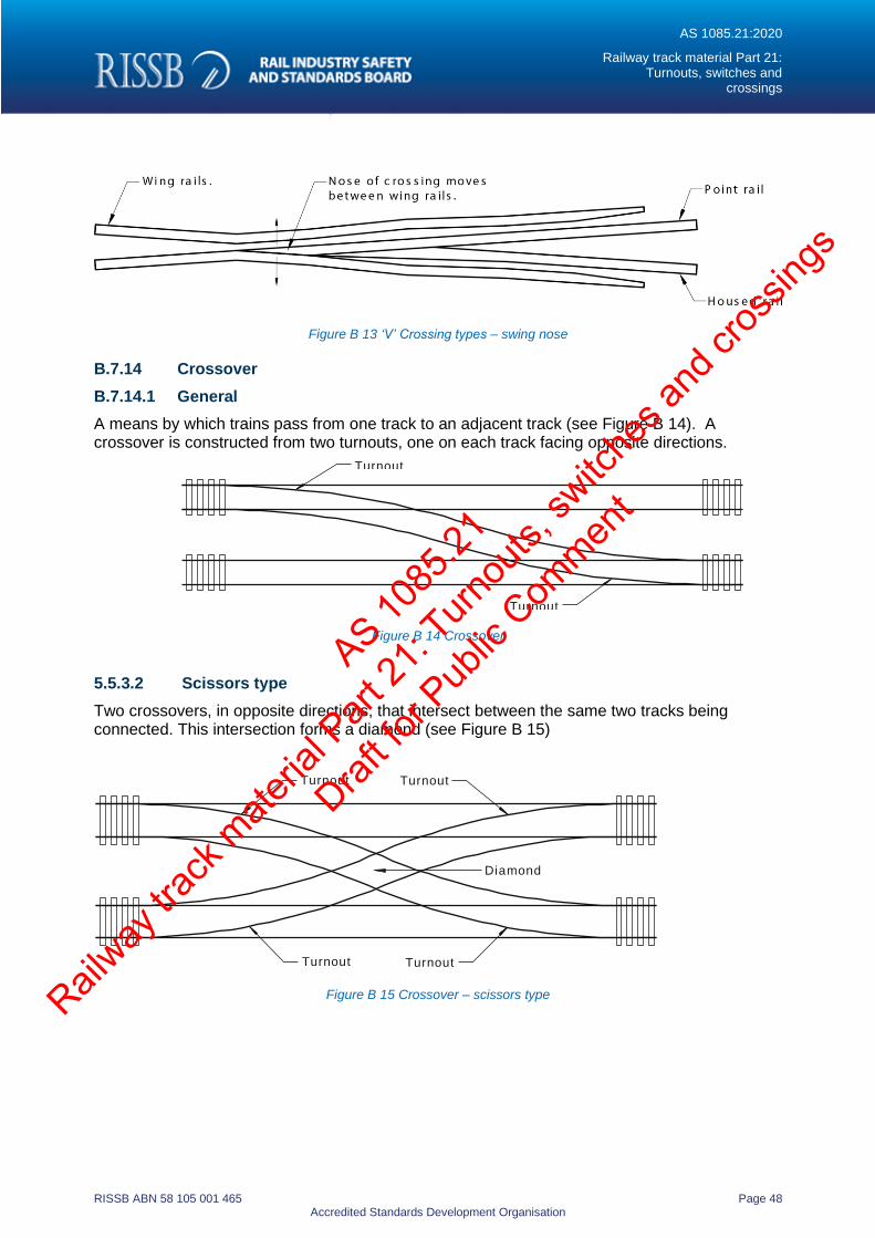
AS 1085.21:2020
Railway track material Part 21: Turnouts, switches and
crossings
RISSB ABN 58 105 001 465 Page 48 Accredited Standards Development Organisation
Figure B 13 ‘V’ Crossing types – swing nose
B.7.14 Crossover
B.7.14.1 General
A means by which trains pass from one track to an adjacent track (see Figure B 14). A crossover is constructed from two turnouts, one on each track facing opposite directions.
Figure B 14 Crossover
5.5.3.2 Scissors type
Two crossovers, in opposite directions, that intersect between the same two tracks being connected. This intersection forms a diamond (see Figure B 15)
Figure B 15 Crossover – scissors type
Turnout
Turnout
Turnout Turnout
Diamond
Turnout Turnout
AS 1085
.21
Railway
track
mate
rial P
art 21
: Turn
outs,
switc
hes a
nd cr
ossin
gs
Draft fo
r Pub
lic Com
ment
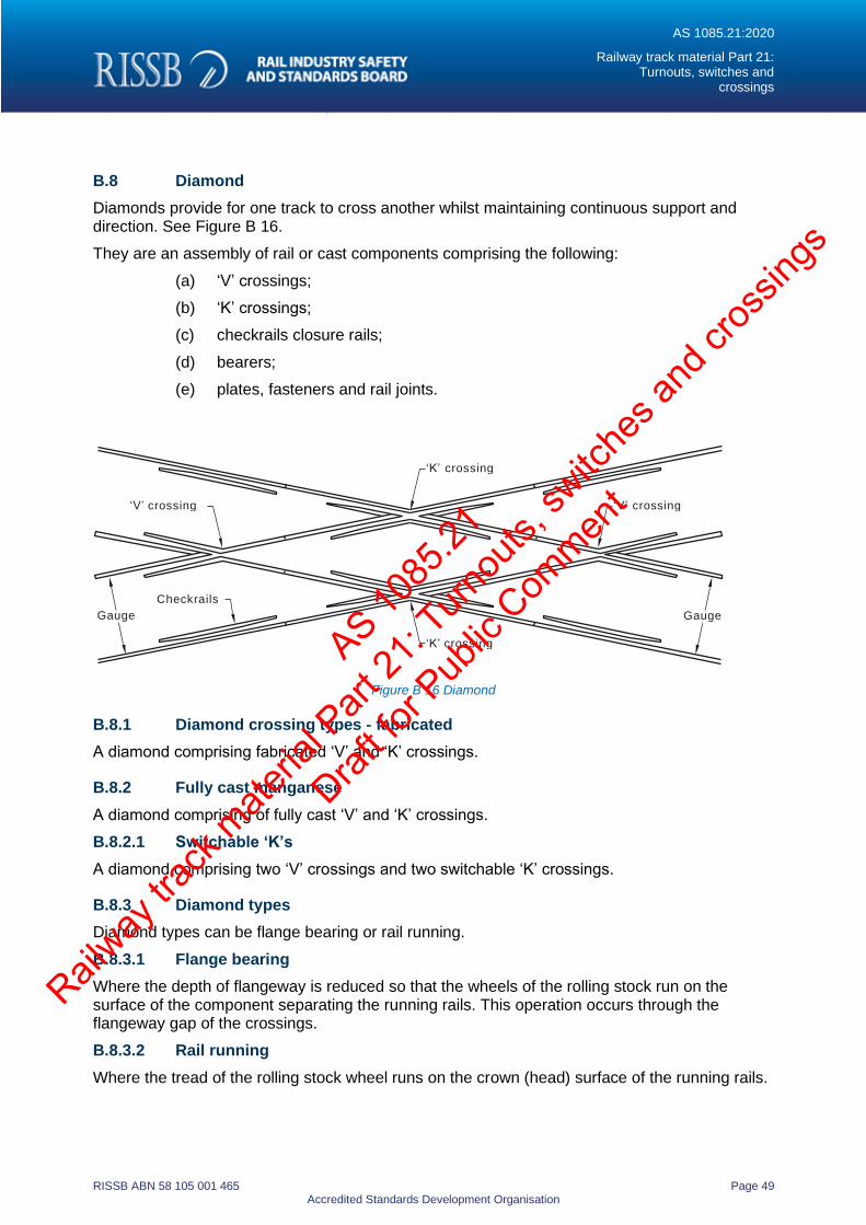
AS 1085.21:2020
Railway track material Part 21: Turnouts, switches and
crossings
RISSB ABN 58 105 001 465 Page 49 Accredited Standards Development Organisation
B.8 Diamond
Diamonds provide for one track to cross another whilst maintaining continuous support and direction. See Figure B 16.
They are an assembly of rail or cast components comprising the following:
(a) ‘V’ crossings;
(b) ‘K’ crossings;
(c) checkrails closure rails;
(d) bearers;
(e) plates, fasteners and rail joints.
Figure B 16 Diamond
B.8.1 Diamond crossing types - fabricated
A diamond comprising fabricated ‘V’ and ‘K’ crossings.
B.8.2 Fully cast manganese
A diamond comprising of fully cast ‘V’ and ‘K’ crossings.
B.8.2.1 Switchable ‘K’s
A diamond comprising two ‘V’ crossings and two switchable ‘K’ crossings.
B.8.3 Diamond types
Diamond types can be flange bearing or rail running.
B.8.3.1 Flange bearing
Where the depth of flangeway is reduced so that the wheels of the rolling stock run on the surface of the component separating the running rails. This operation occurs through the flangeway gap of the crossings.
B.8.3.2 Rail running
Where the tread of the rolling stock wheel runs on the crown (head) surface of the running rails.
‘K’ crossing
‘V’ crossing ‘V’ crossing
Checkrails
Gauge Gauge
‘K’ crossing AS 1085
.21
Railway
track
mate
rial P
art 21
: Turn
outs,
switc
hes a
nd cr
ossin
gs
Draft fo
r Pub
lic Com
ment
AS 1085.21:2020
Railway track material Part 21: Turnouts, switches and
crossings
RISSB ABN 58 105 001 465 Page 50 Accredited Standards Development Organisation
B.9 Dual gauge turnouts
Turnouts that are constructed with a mixture of both Standard Gauge (1435 mm) and Broad Gauge (1600 mm) widths, or Standard and Narrow Gauge (1067 mm) widths utilizing a common rail.
B.10 Expansion switch
An assembly comprising two rails appropriately matched and fastened at the longitudinal interface to provide virtual continuity of the running rail and gauge faces while allowing controlled longitudinal slip (see Figure B 17)..
Expansion switches provide a level of control for rail stresses when tracks are attached to sub- structures (e.g. steel underbridges) which are also subject to temperature related expansion and contraction.
Expansion switches comprise:
(a) switch and stockrail assemblies;
(b) bearers;
(c) plates, fasteners and rail joints.
Figure B 17 Typical expansion switch
B.11 Fastening system
A combination of base plates, and fasteners used to attach the rail to the bearer. The system may include spikes, pads, clips, insulators and anchors.
B.12 Fishplate
A metal joint bar used to connect adjacent rails. Refer to AS 1085.2.
AS 1085
.21
Railway
track
mate
rial P
art 21
: Turn
outs,
switc
hes a
nd cr
ossin
gs
Draft fo
r Pub
lic Com
ment
AS 1085.21:2020
Railway track material Part 21: Turnouts, switches and
crossings
RISSB ABN 58 105 001 465 Page 51 Accredited Standards Development Organisation
B.13 Flangeway
B.13.1 General
The space adjacent to the running rail to allow for the passage of wheel flanges (see Figure B 18).
Figure B 18 Flangeway
B.13.2 Flangeway depth
The vertical distance between the top running surface and the top of the blocks/chocks separating the running and guarding surfaces to ensure wheel flange clearance.
B.13.3 Flangeway width
The distance between the running and checking surfaces to ensure wheel flange clearance or guidance.
B.13.4 Flangeway running
Where the toe of the wheel runs on a raised flangeway block. Used in crossings in urban environments for noise abatement or in light rail where there is risk the wheelset width is too small to transfer from the wing rail to the crossing nose with larger angle crossings.
B.13.5 Flare
The tapered opening at the ends of flangeways to gradually engage wheel flanges and position them to pass through flangeways.
B.14 Heel block
B.14.1 General
Single or multiple blocks, depending on switch type, that rigidly fix the switch rail to the adjacent rail in the correct geometric configuration.
B.14.2 Heel fishplate
The special or set fishplate at the heel of pivot heel switches which supports the switch.
AS 1085
.21
Railway
track
mate
rial P
art 21
: Turn
outs,
switc
hes a
nd cr
ossin
gs
Draft fo
r Pub
lic Com
ment
AS 1085.21:2020
Railway track material Part 21: Turnouts, switches and
crossings
RISSB ABN 58 105 001 465 Page 52 Accredited Standards Development Organisation
B.14.3 Heel joint
The joint around which a pivot heeled switch rotates. The joint is made up of a steel block with fishplates and bolts which are designed to allow this movement.
B.14.4 Heel point
Actual heel joint, for pivot heeled switches, or theoretical point, for flexible switches, that is used for turnout/switch design.
B.15 In-bearer
A bearer of specific shape that is used at a set of switches or swing nose crossing (see section B.7.13.4) to house the switch operating rodding. This eliminates the rodding being located in a bay between bearers.
B.16 Asymmetric rail
Asymmetric rail is used primarily for the manufacture of switches. The short height of the switch rail permits resilient fastening of the gauge side of the stockrail. Refer to AS 1085.1 for rail profile.
B.17 Rail brace
A cast or fabricated component that supports the rail in a fixed position. The rail brace is attached to the stockrail.
B.18 Rail brace plates
Rail brace plates are used under the switch assembly to which a rail brace is attached and this in turn is attached to the stockrail. The plates are distinguishable by a number stamped at the end.
B.19 Resilient / elastic fastenings
Resilient fastening assemblies provide a flexible restraint that holds the rail in position on the sleeper or other support structures by providing a spring force of known magnitude. The assembly may, if required, also provide load spreading, impact attenuation and electrical isolation.
NOTE: Refer to AS 1085.19.
B.20 Slip
B.20.1 General
Also known as a ‘compound’. Allows two tracks to cross each other or diverge, but unlike a diamond, contain sets of switches to allow movement from one line to the other (see Figure B 19).
A slip comprises the following:
(a) Switch and stockrail assemblies.
(b) ‘V’ crossings;
(c) ‘K’ crossings;
(d) checkrails;
AS 1085
.21
Railway
track
mate
rial P
art 21
: Turn
outs,
switc
hes a
nd cr
ossin
gs
Draft fo
r Pub
lic Com
ment
AS 1085.21:2020
Railway track material Part 21: Turnouts, switches and
crossings
RISSB ABN 58 105 001 465 Page 53 Accredited Standards Development Organisation
(e) closure rails;
(f) bearers;
(g) plates, fasteners and rail joints.
B.20.2 Double
A slip with four sets of switch assemblies (see Figure B 19(b)).
B.20.3 Single
A slip with two sets of switch assemblies (see Figure B 19 (a)).
Figure B 19 Slip type – single/double
AS 1085
.21
Railway
track
mate
rial P
art 21
: Turn
outs,
switc
hes a
nd cr
ossin
gs
Draft fo
r Pub
lic Com
ment
AS 1085.21:2020
Railway track material Part 21: Turnouts, switches and
crossings
RISSB ABN 58 105 001 465 Page 54 Accredited Standards Development Organisation
B.21 Switch assembly
B.21.1 General
A switch assembly consists of either a right and left hand switch and stockrail, complete with associated plating and fastenings. Also known as ‘points’.
B.21.2 Operating equipment
The switch machine or lever, rodding, detectors, brackets and fastenings that control the movement of the switch.
B.21.3 Switch assembly types
B.21.3.1 Heavy duty
A switch with a thickened tip that must be used with a joggled stockrail to ensure the running face of the running rail is co-linear(see Figure B 20) .
Figure B 20 Switch type – heady duty
B.21.3.2 Housed
A heavy duty switch and joggled stockrail equipped with a ‘housing’ (see Figure B 21).
The housing is a specially machined component with a hardened checking face fitting above the switch to act as a checkrail for the opposite switch and joggle. Where both switches are required to be heavy duty a housing is required on one of the switches.
Figure B 21 Switch type - housed switches
AS 1085
.21
Railway
track
mate
rial P
art 21
: Turn
outs,
switc
hes a
nd cr
ossin
gs
Draft fo
r Pub
lic Com
ment
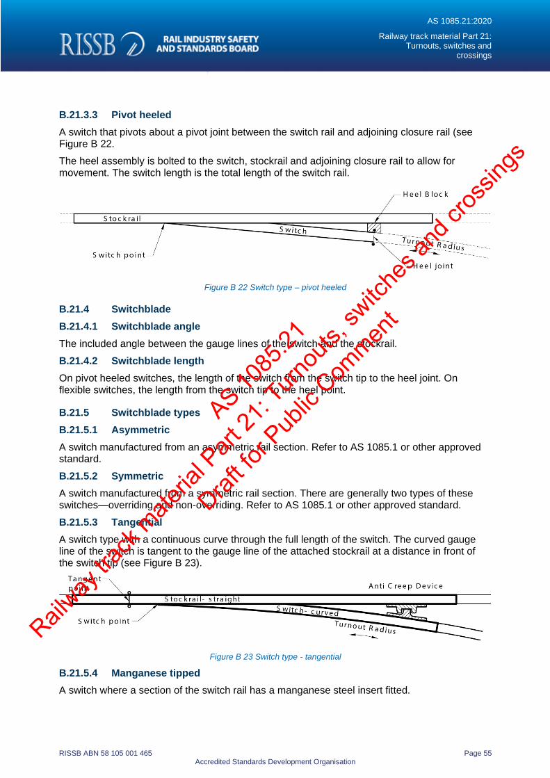
AS 1085.21:2020
Railway track material Part 21: Turnouts, switches and
crossings
RISSB ABN 58 105 001 465 Page 55 Accredited Standards Development Organisation
B.21.3.3 Pivot heeled
A switch that pivots about a pivot joint between the switch rail and adjoining closure rail (see Figure B 22.
The heel assembly is bolted to the switch, stockrail and adjoining closure rail to allow for movement. The switch length is the total length of the switch rail.
Figure B 22 Switch type – pivot heeled
B.21.4 Switchblade
B.21.4.1 Switchblade angle
The included angle between the gauge lines of the switch and the stockrail.
B.21.4.2 Switchblade length
On pivot heeled switches, the length of the switch from the switch tip to the heel joint. On flexible switches, the length from the switch tip to the heel point.
B.21.5 Switchblade types
B.21.5.1 Asymmetric
A switch manufactured from an asymmetric rail section. Refer to AS 1085.1 or other approved standard.
B.21.5.2 Symmetric
A switch manufactured from a symmetric rail section. There are generally two types of these switches—overriding and non-overriding. Refer to AS 1085.1 or other approved standard.
B.21.5.3 Tangential
A switch type with a continuous curve through the full length of the switch. The curved gauge line of the switch is tangent to the gauge line of the attached stockrail at a distance in front of the switch tip (see Figure B 23).
Figure B 23 Switch type - tangential
B.21.5.4 Manganese tipped
A switch where a section of the switch rail has a manganese steel insert fitted.
AS 1085
.21
Railway
track
mate
rial P
art 21
: Turn
outs,
switc
hes a
nd cr
ossin
gs
Draft fo
r Pub
lic Com
ment
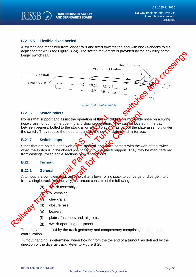
AS 1085.21:2020
Railway track material Part 21: Turnouts, switches and
crossings
RISSB ABN 58 105 001 465 Page 56 Accredited Standards Development Organisation
B.21.5.5 Flexible, fixed heeled
A switchblade machined from longer rails and fixed towards the end with blocks/chocks to the adjacent stockrail (see Figure B 24). The switch movement is provided by the flexibility of the longer switch rail.
Figure B 24 Flexible switch
B.21.6 Switch rollers
Rollers that support and assist the operation of the switchblade or moveable nose on a swing nose crossing, during the opening and closing operation. They can be located in the bay between bearers, bolted to the stockrail or switch blade, or as part of the plate assembly under the switch. They reduce the need to lubricate the switch plate/switch interface.
B.21.7 Switch stops
Stops that are bolted to the web of the stockrail and make contact with the web of the switch when the switch is in the closed position to provide lateral support. They may be manufactured from castings, rolled angle sections or extended bolts.
B.22 Turnout
B.22.1 General
A turnout is a complete track assembly that allows rolling stock to converge or diverge into or from a single track (respectively). A turnout consists of the following:
(a) switch assembly;
(b) ‘V’ crossing;
(c) checkrails;
(d) closure rails;
(e) bearers;
(f) plates, fasteners and rail joints;
(g) switch operating equipment.
Turnouts are identified by the track geometry and componentry comprising the completed configuration.
Turnout handing is determined when looking from the toe end of a turnout, as defined by the direction of the diverge track. Refer to Figure B 25.
AS 1085
.21
Railway
track
mate
rial P
art 21
: Turn
outs,
switc
hes a
nd cr
ossin
gs
Draft fo
r Pub
lic Com
ment
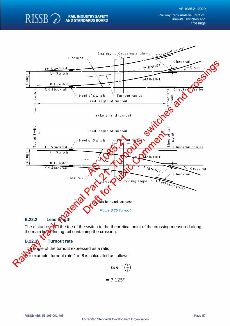
AS 1085.21:2020
Railway track material Part 21: Turnouts, switches and
crossings
RISSB ABN 58 105 001 465 Page 57 Accredited Standards Development Organisation
Figure B 25 Turnout
B.22.2 Lead length
The distance from the toe of the switch to the theoretical point of the crossing measured along the main line running rail containing the crossing.
B.22.3 Turnout rate
The angle of the turnout expressed as a ratio.
For example, turnout rate 1 in 8 is calculated as follows:
= 𝑡𝑎𝑛−1 (1
8)
= 7.125°
AS 1085
.21
Railway
track
mate
rial P
art 21
: Turn
outs,
switc
hes a
nd cr
ossin
gs
Draft fo
r Pub
lic Com
ment
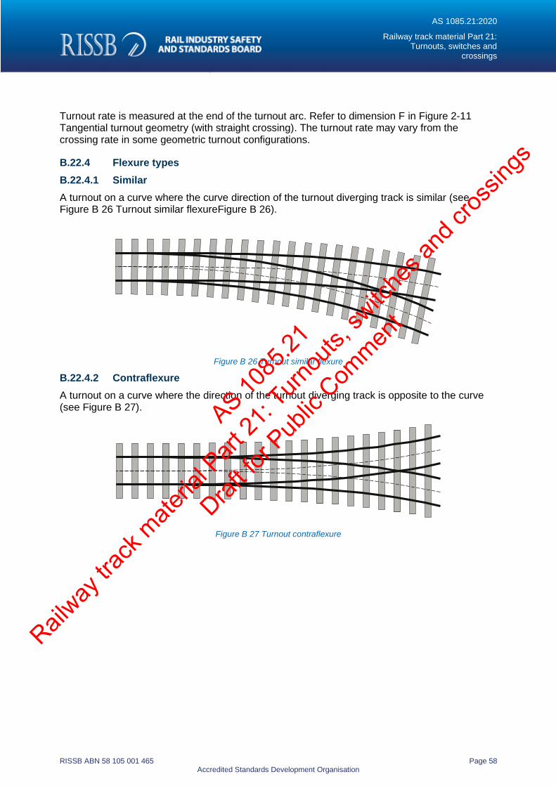
AS 1085.21:2020
Railway track material Part 21: Turnouts, switches and
crossings
RISSB ABN 58 105 001 465 Page 58 Accredited Standards Development Organisation
Turnout rate is measured at the end of the turnout arc. Refer to dimension F in Figure 2-11 Tangential turnout geometry (with straight crossing). The turnout rate may vary from the crossing rate in some geometric turnout configurations.
B.22.4 Flexure types
B.22.4.1 Similar
A turnout on a curve where the curve direction of the turnout diverging track is similar (see Figure B 26 Turnout similar flexureFigure B 26).
Figure B 26 Turnout similar flexure
B.22.4.2 Contraflexure
A turnout on a curve where the direction of the turnout diverging track is opposite to the curve (see Figure B 27).
Figure B 27 Turnout contraflexure
AS 1085
.21
Railway
track
mate
rial P
art 21
: Turn
outs,
switc
hes a
nd cr
ossin
gs
Draft fo
r Pub
lic Com
ment
AS 1085.21:2020
Railway track material Part 21: Turnouts, switches and
crossings
RISSB ABN 58 105 001 465 Page 59 Accredited Standards Development Organisation
Appendix C Information to be supplied by the purchaser
(Informative)
Provided over page is an example form to assist purchasers when ordering and/or seeking quotations for the supply of turnouts, switches and crossings.
AS 1085
.21
Railway
track
mate
rial P
art 21
: Turn
outs,
switc
hes a
nd cr
ossin
gs
Draft fo
r Pub
lic Com
ment
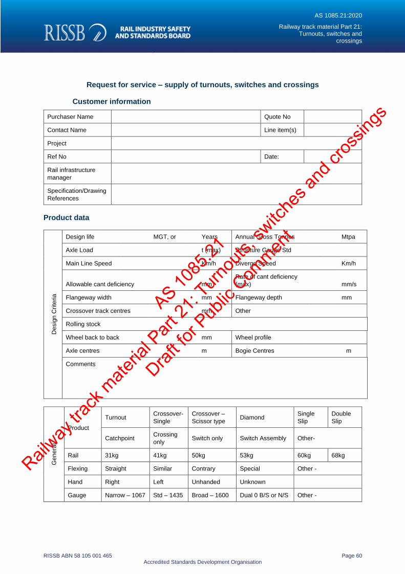
AS 1085.21:2020
Railway track material Part 21: Turnouts, switches and
crossings
RISSB ABN 58 105 001 465 Page 60 Accredited Standards Development Organisation
Request for service – supply of turnouts, switches and crossings
Customer information
Purchaser Name Quote No
Contact Name Line item(s)
Project
Ref No Date:
Rail infrastructure
manager
Specification/Drawing
References
Product data
Desig
n C
rite
ria
Design life MGT, or Years Annual Gross Tonnes Mtpa
Axle Load t (max) Structure Gauge Std
Main Line Speed Km/h Diverge Speed Km/h
Allowable cant deficiency mm
Rate of cant deficiency
(max) mm/s
Flangeway width mm Flangeway depth mm
Crossover track centres mm Other
Rolling stock
Wheel back to back mm Wheel profile
Axle centres m Bogie Centres m
Comments
Ge
ne
ral
Product
Turnout Crossover-
Single
Crossover –
Scissor type Diamond
Single
Slip
Double
Slip
Catchpoint Crossing
only Switch only Switch Assembly Other-
Rail 31kg 41kg 50kg 53kg 60kg 68kg
Flexing Straight Similar Contrary Special Other -
Hand Right Left Unhanded Unknown
Gauge Narrow – 1067 Std – 1435 Broad – 1600 Dual 0 B/S or N/S Other -
AS 1085
.21
Railway
track
mate
rial P
art 21
: Turn
outs,
switc
hes a
nd cr
ossin
gs
Draft fo
r Pub
lic Com
ment
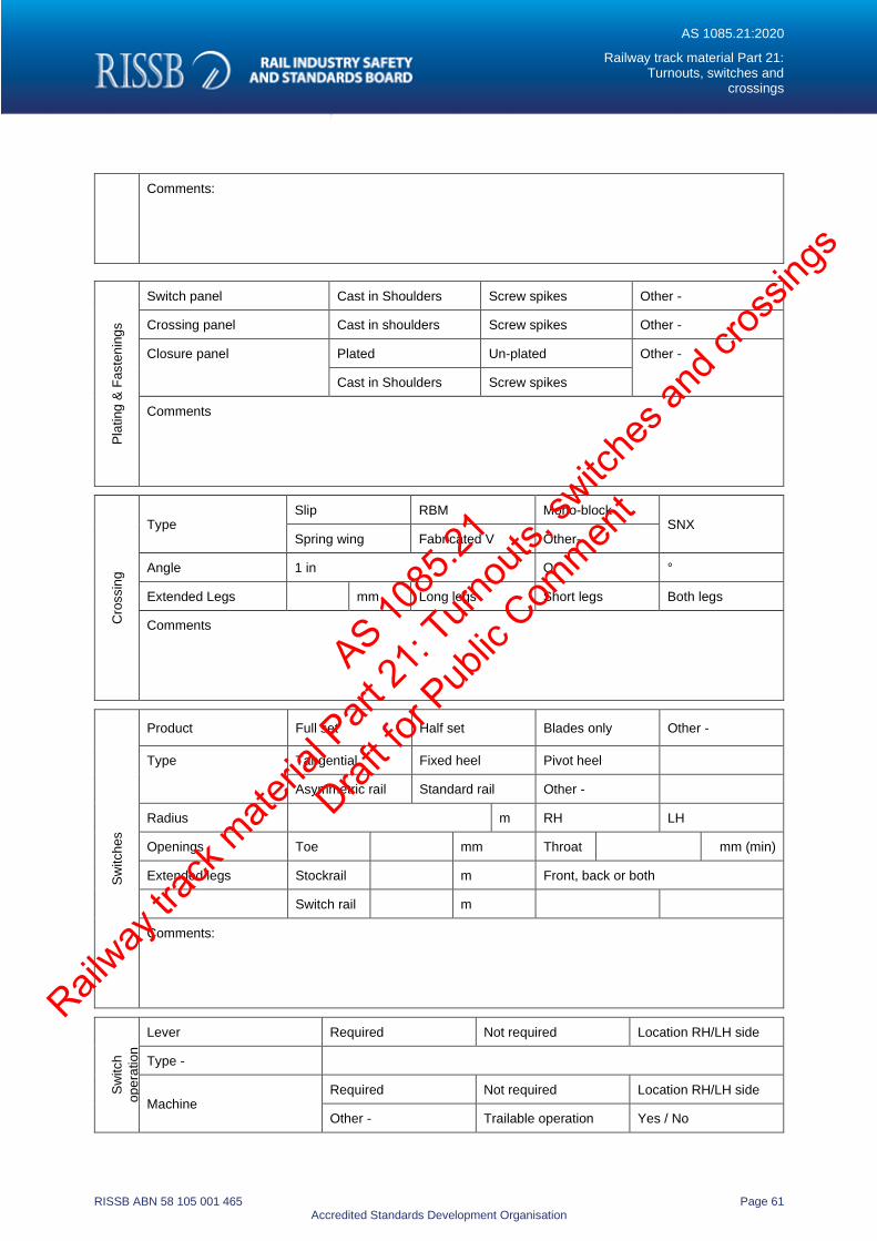
AS 1085.21:2020
Railway track material Part 21: Turnouts, switches and
crossings
RISSB ABN 58 105 001 465 Page 61 Accredited Standards Development Organisation
Comments:
Pla
ting
& F
aste
nin
gs
Switch panel Cast in Shoulders Screw spikes Other -
Crossing panel Cast in shoulders Screw spikes Other -
Closure panel Plated Un-plated Other -
Cast in Shoulders Screw spikes
Comments
Cro
ssin
g
Type Slip RBM Mono-block
SNX Spring wing Fabricated V Other-
Angle 1 in Or °
Extended Legs mm Long legs Short legs Both legs
Comments
Sw
itch
es
Product Full set Half set Blades only Other -
Type Tangential Fixed heel Pivot heel
Asymmetric rail Standard rail Other -
Radius m RH LH
Openings Toe mm Throat mm (min)
Extended legs Stockrail m Front, back or both
Switch rail m
Comments:
Sw
itch
op
era
tio
n
Lever Required Not required Location RH/LH side
Type -
Machine Required Not required Location RH/LH side
Other - Trailable operation Yes / No
AS 1085
.21
Railway
track
mate
rial P
art 21
: Turn
outs,
switc
hes a
nd cr
ossin
gs
Draft fo
r Pub
lic Com
ment
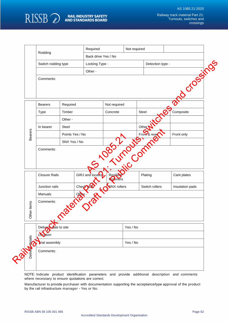
AS 1085.21:2020
Railway track material Part 21: Turnouts, switches and
crossings
RISSB ABN 58 105 001 465 Page 62 Accredited Standards Development Organisation
Rodding Required Not required
Back drive Yes / No
Switch rodding type Locking Type - Detection type -
Other -
Comments:
Be
are
rs
Bearers Required Not required
Type Timber Concrete Steel Composite
Other -
In bearer Steel Other -
Points Yes / No Front & rear Front only
SNX Yes / No
Comments:
Oth
er
ite
ms
Closure Rails GIRJ and location Resilient
fasteners
Plating Cant plates
Junction rails Check rails SNX rollers Switch rollers Insulation pads
Manuals Other -
Comments:
Deliv
ery
de
tails
Delivery date to site Yes / No
Location
Trial assembly Yes / No
Comments:
NOTE: Indicate product identification parameters and provide additional description and comments
where necessary to ensure quotations are correct.
Manufacturer to provide purchaser with documentation supporting the acceptance/type approval of the product
by the rail infrastructure manager - Yes or No.
AS 1085
.21
Railway
track
mate
rial P
art 21
: Turn
outs,
switc
hes a
nd cr
ossin
gs
Draft fo
r Pub
lic Com
ment
AS 1085.21:2020
Railway track material Part 21: Turnouts, switches and
crossings
RISSB ABN 58 105 001 465 Page 63 Accredited Standards Development Organisation
Appendix D Bibliography
AS 1085.19 Railway track materials, Part 19: Resilient fastening assemblies
AS 7633 – Railway infrastructure clearances
AS 1085
.21
Railway
track
mate
rial P
art 21
: Turn
outs,
switc
hes a
nd cr
ossin
gs
Draft fo
r Pub
lic Com
ment
AS 1085.21:2020
Railway track material Part 21: Turnouts, switches and
crossings
RISSB ABN 58 105 001 465 Page 64 Accredited Standards Development Organisation
RISSB Australian Standards Development Process
The Standards development process is rigorous and transparent.
Authors work with RISSB's Standards Development Managers and Development Groups to ensure that products are
acceptable to industry. Standing Committees oversee this work and ensure that proper governance and process is
followed. The products are exposed to the public and industry for comment and validated by an independent
validator.
Once agreed by the Development Groups, Standing Committees and Validator, the drafts are passed to the RISSB
Board for approval.
The same process is used in developing other RISSB products, although Guidelines are not exposed to the public for comment or validated, given their non-binding nature.
Standards Development and Accreditation Committee
RISSB is accredited by the Standards Development and Accreditation Committee (SDAC), and all Standards
produced by RISSB since 31 July 2007 are published as Australian Standards.
The Standards Development and Accreditation Committee audits RISSB annually to ensure that RISSB’s processes
are in accordance with SDAC accreditation requirements.
Sales and distribution
Australian Standards developed by RISSB are sold and marketed through SAI Global. For further information, please
visit www.saiglobal.com.
Financial members of RISSB are granted access with membership.
About Rail Industry Safety and Standards Board
The Rail Industry Safety and Standards Board is a not for profit company limited by guarantee. Wholly owned by its
funding members, RISSB is required to apply the whole of its income and assets to achieving the objects listed in its
constitution.
RISSB is responsible for the development and management of Standards, Rules, Codes of Practice and Guidelines
for the Australian rail industry.
For further information, visit www.rissb.com.au
AS 1085
.21
Railway
track
mate
rial P
art 21
: Turn
outs,
switc
hes a
nd cr
ossin
gs
Draft fo
r Pub
lic Com
ment