Embed Size (px)
Citation preview
This page has been reformatted by Knovel to provide easier navigation.
25 Railways
D S Currie FEng, FICE, MIMechEDirector of Civil EngineeringBritish Railways
Contents
25.1 Earthworks and drainage 25/325.1.1 Site investigation 25/325.1.2 General 25/3
25.2 Ballast 25/425.2.1 Track profile 25/5
25.3 Sleepers 25/625.3.1 Timber sleepers and sleeper spacing 25/625.3.2 Steel sleepers 25/625.3.3 Concrete sleepers 25/7
25.4 Fastenings 25/9
25.5 Rails 25/1025.5.1 Rail failures 25/11
25.6 Curved track 25/12
25.7 Welded track 25/1425.7.1 Fastening welded rails 25/15
25.8 Switches and crossings 25/1525.8.1 Switches 25/1525.8.2 Crossings 25/1525.8.3 Leads 25/16
25.9 Slab track 25/1625.9.1 Prefabricated slab track 25/17
25.10 Track maintenance and renewal 25/18
25.11 Railway structures 25/2025.11.1 General 25/2025.11.2 Stations 25/2025.11.3 Bridges and viaducts 25/2125.11.4 Clearances 25/2225.11.5 Refuges 25/22
25.12 Inspection and maintenance of structures 25/22
25.13 Research, development and internationalcollaboration 25/23
Bibliography 25/23
25.1 Earthworks and drainage
The contours of the territory to be crossed by a railway areobviouslv decisive as to its average gradient but they are also thebackground to fixing the maximum permissible gradient withinthe limits of tractive and braking adhesion. The lower thedifference between average gradient and maximum gradient thegreater is the practicable train load and the lesser are thedeviations from constant-speed running. The minimum curva-ture to be used also determines the differences between the linespeed limit and local speed restrictions. Long curves of smallradius on heavy gradients may involve derailment hazards forvery long and heavy trains, arising from braking or tractiveeffort surges along the train. Both maximum gradient andminimum curvature have a large effect on the earthworks cost ofconstructing a railway and, because of this, the ideal of con-stant-speed running is often subject to heavy qualification. Thisis particularly the case in mountainous country.
Railway alignment needs to be planned to give a volumebalance between excavation in cuttings and tipping in embank-ments, subject to the material excavated being suitable fortipping to form embankments and subject to minimizing thehaul of the excavated soil. Recourse to borrow pits for embank-ments and spoil hauls for cuttings should be minimized.
The route may also be affected by other considerations whichmay be economic, environmental or technical. These wouldbecome apparent in a full site investigation, where such mattersas previous mining activity, underground services, effect onneighbouring structures, nature of the groundwater table andwatercourses would be taken into account. Guidance is avail-able in relevant Codes of Practice, such as BS 6031 and BS 5930.(See also Chapters 9, 11 and 17.)
25.1.1 Site investigation
This will vary according to the extent of the problem. At theoutset, a preliminary study may give adequate information tospecify the route corridor from geological maps and memoirs,topographical maps and aerial photographs. Earth satelliteimagery with interpretation of selective wavebands by special-ists in remote sensing can indicate important features. Watertable conditions may vary throughout the year from thoseobtaining at the time of exploration.
For more localized investigation, the type of equipment(augers, percussion and rotary tools, penetration heads, loadingplates, pumps), instruments (piezometers, inclinometer tubes,seismometers, resistivity meters, gravimeters, etc.) must bechosen according to conditions. Relevant disturbed or undis-turbed samples should be procured for testing. According to thetype of ground, the construction and the design philosophyapplied, it may be necessary to carry out full-scale site testingwith long-term monitoring of instruments.
25.1.2 General
In the past, railways have been maintained over poor ground,with inadequate trackbed materials with a high input of labourtime and at slow or moderate train speeds. Although thefollowing concepts may be used in modifying old railways, thebasic approach is to obtain a minimum maintenance high-speedrailway accepting normal freight traffic on conventionalsleepers.
25.1.2.1 Cutting slopes
Slopes in natural ground may be constructed at safe anglesaccording to the properties of the soil.
25.1.2.2 Rock cuttings
British Railways has indicated safe slopes for rock cuttings andangles of repose for rock embankments in a chart reproduced asTable 3 in BS 6031. If steep cuttings in rock are essential, then itis necessary to apply engineering geology concepts to assessjoint sets in relation to the direction of slope. Rock anchors,rock bolts and sprayed concrete may be used to assure stabilitybefore considering the use of mass-retaining walls. Chalk andcertain other soft rocks are susceptible to weathering and frostaction and may be protected by vegetation cover.
25.1.2.3 Soil cuttings
Where the slopes are in non-cohesive sands and gravels, theangle of repose is the limiting gradient (with a maximum valueof 1:1). Usually, the gradient is shallower than this due to thepresence of finer layers in the soil system or a silt or clay matrixaround the gravel. The non-cohesive soils tend to be self-draining but erosion can occur when water springs part way upthe slope. At such locations a non-woven geotextile filter can beplaced and covered with uniform coarse stone (away from thesun's rays) which will hold the fabric in place.
Drainage measures should take the form of preventing waterreaching the slope and of removing it from the slope. Unlinedditches behind the crest of the slope increase the hazard.Drainage trenches, whether behind or below the crest, should bedesigned to intercept water and have impermeable membranesbelow them and on the downfill face to prevent water oncecollected from re-entering the soil. Modern counterfort orbuttress drains differ greatly from the original open forms. Likeall drains they should be lined with a geotextile layer to preventerosion behind and fouling within them. The top 1 or 2mshould be composed of impermeable material, either compactedclay fill or a system of stone and plastics membrane to preventsurface water reaching deep into the ground, where it couldcause internal pore water pressure at likely slip surfaces.
In some cases, there is a mantle of more permeable silt or sandoverlying the older clay and, if possible, a lateral interceptordrain should be placed about 20 m behind the crest to preventthe fast seepage of water.
In addition to the above rotational slides, translational slidescan occur, usually as a shallow mass moving on a planarsurface. They can take the form of slab or block slides, wedgefailures, debris slides and flow slides. These possibilities areassessed in the site investigation. Mires are formed as peat is laiddown in a specific sequence with variations in soil content,dimensions of fibre (roots, trees, etc.) and extent of humifica-tion. Peats reduce greatly in volume under the effects of loadingand drainage. In making cuttings in a peat system, quitesubstantial waterflow can occur and a filter is advised to dealwith fine particles otherwise carried from the slope.
In all cases of cuttings, other engineering works at groundlevel should be considered. Urban or industrial constructioninvolves roads which act as catchments to deliver water to localdrainage systems and also water services: if these are defectiveand near the slope, water can flow to increase pore pressure andprecipitate a slip. Similarly, surcharging, especially if accompa-nied by dynamic loads from construction plant or the placing ofstorage containers, can seriously reduce the factor of safety.
Steep rock faces, chalk cliffs, and boulder-strewn hill slopesmay present rockfall or chalkfall problems which may needspecial watchmen, signalling provisions, special fence, apron ortunnel protection.
25.1.2.4 Embankments
The nature of the natural soil to receive the embankment must
be investigated. If it is too weak to receive the embankmentloading at the rate of placing likely to be used by the contractor,failure could occur. A total stress analysis is applicable for this.The conventional technique is to place berms as counterweightsat the position of heave. A modern alternative is the use ofreinforcing geotextiles or meshes (usually of plastics) to resisttensile forces. The fabric is laid directly on the ground andcovered with a granular layer at least 200 mm thick; this acts asa filter and permits construction plant to move easily over thesite without sinking into the underlying soft soil. Further fabricor mesh is laid at higher levels, the number and spacing of layersdepending upon the engineering properties of the specialist typeof material chosen.
Slope angles. Embankments may be formed at angles varyingfrom ratios of 1:1 horizontal to vertical for crushed rock andgravels to 2.5:1 or even shallower for clays and silts. The slopeangles depend both on the material and rainfall. For modernrailways, peat should not be used as fill material.
The surfaces of slopes should be protected from erosion. Thismay occur naturally as vegetation is established, followed by aprotective topsoil. If surface erosion is a problem, varioussystems are available, such as spraying with a seed mulch,turving, placing filter fabrics held down by gravel layers or usinga honeycomb mesh to hold seeded compost in place.
Rockfalls. Vertical or sloping rock faces may erode or toppleto cause rocks of various sizes to fall towards the running line.Although vegetation may help by bonding superficially, protec-tion must involve coping with the energy of rockfall andremoving the debris regularly. If space is available, one or twoberms are constructed between the base of the slope and therailway to collect scree. For some faces, a plastic geomesh isadequate.
Reinforced earth. The dimensions of embankments and ofgravity-retaining structures can be reduced by the inclusion ofvarious strengthening meshes, fabrics, strips and rods of metal,glass fibre or plastics. The tensile resistance of these elements isapplied to the adjacent granular soil to produce a compositesystem permitting the construction of vertical faces in the fill.These external faces are protected by facing elements usually ofconcrete, resulting in a structure which is economic and whichcan accommodate settlement. The various qualities of creep,longevity of reinforcement, corrosion, etc. are still the subject ofstudy but many such structures exist throughout the world,including railway environments. There are none so far beneath ahigh-speed running line and, in this particular case, such systemscan be installed up to a horizontal distance of 5 m from therunning line.
Trackbed designs. The thickness of subsleeper construction(trackbed) is a function of number and size of axle loadings andof the subgrade soil. Modern railways assess the subgrade soil inone of two approaches: (1) the classification of the soil accord-ing to its physical properties and taking account of the watertable; or (2) correlating some measured strength or modulus ofthe subgrade with an empirical design chart. The thickness ofthe trackbed may also depend upon its component layers toprotect against frost, water and particle movement. In veryfrost-prone areas, such as Central Europe, the thickness ofballast for frost protection exceeds that which might be requiredfor prevention of bearing capacity failure.
The thickness of ballast (all dimensions are below bottom ofsleeper) is a minimum of 200 mm to permit tamping machines tooperate. Although new ballast injection machines would permitthis to be reduced, a high-speed or high-axle-load railway wouldrequire 300 to 500 mm thickness for minimum maintenance.
Drainage. The control of water in the trackbed is a majorfactor in designing the construction layers in relation to the typeof subgrade soil as discussed above. Soils such as sands andgravels which may be drained fairly easily do not present a greatproblem unless there is an artesian head: in this case, there canbe a slow upward migration of fine or medium sand under trackvibration combined with water flow, and a geotextile is neces-sary to hold down this sand. Cohesive soils cannot be drainedeasily and the installation of a channel or pipe will only reducethe pore water pressure to invert level in its immediate vicinity.It is not practical to attempt to remove water from clay in thisway as such a large number of drains would be required. Ifwater arrives through precipitation or by flow from adjacentareas, then a relatively small amount is sufficient to producedeleterious changes in pore pressure and so it is practical toprovide drains to intercept and remove this free water. Most ofthe water in cohesive soil is held in capillary suction.
The relationship between the moisture content of cohesivesoil and the water table is complex, depending upon the overconsolidation ratio (OCR) of the soil. Weathering reduces theOCR effect at the surface.
One object in designing the system of drains and track is toproduce a maintenance-free system or one needing minimalattention. Channel drains are readily accessible for cleaning anddeal with rainwater, they can be laid at very slight gradients andcan deliver at catchpits to deeper pipe carriers if necessary.Many pipe drains act both as collectors and carriers, allowingwater to enter at open joints or through perforations. Thevarious forms of pipe are glazed earthenware, galvanized corru-gated steel, pitch fibre and, now coming more into use becauseof ease of handling, plain or perforated PVC pipe. Geotextilesare of great use in static drainage conditions and most railwaysreport satisfactory results using commercially available filteringnon-woven fabric. For normal purposes, a fully heat-bondedgeotextile with a surface density in the range 100 to 200 g/m2 isacceptable; needle-punched geotextiles should be of slightlyheavier grade. Fabrics placed in quasi-static conditions near thetrack should be of heavier grade up to 350 g/m2, or more ifneedle-punched. Such a geotextile would be placed in the sixfootof a double track line after one track had been cleaned orblanketed. This would prevent slurry from the dirty adjacenttrack flowing across.
A modern standard design for a side drain is a trench linedwith geotextile with a perforated pipe drain running along itsbase; above and around the pipe is placed uniform stone such asballast, with the top of the geotextile lapped over the stoneabout 200 mm below the surface: more stone on the geotextileprotects it from disturbance and from the effect of the ultra-violet rays of the sun. As perforated drains can release as well ascollect water, possibly at susceptible locations, it is often thepractice to place a polyethylene film to line the trench.
25.2 Ballast
Ballast, the material around and below the sleeper, is placed toprovide support and lateral resistance to the sleeper. It permitsadjustment of level and alignment as required and, if this is donemanually, the maximum size of particles should be about50 mm. Ballast should be free-draining, mainly of single size, ofcubical shape but, above all, durable so that there is negligiblevolume change under track loading. The wet attrition value(WAV) gives the best correlation, with minimum maintenancerequirements over the long term and this is determined by thetest described in BS 812:1951, clause 27, which specifies theexact size and type of sample to be used. If particles of differentsize from the 50 to 37.5 mm required in the test are used, then adifferent WAV is obtained. The WAV should not exceed 4% for
good ballast and it is possible to obtain stone with a WAV downto 1%. It is rare for synthetic stone, such as slag, to haveadequate wet attrition properties and they may generally begrouped with most limestones as being unsuitable to be incontact with the sleeper. Hardness is difficult to define inrelation to other tests but, if the ultrasonic pulse velocity of thehomogeneous mineral is 6000 m/s or greater, the stone will besuitable. In severe climates, a freezing and thawing test may beapplicable.
The dimensions should conform by weight to the valuesshown in Table 25.1; and the 1.18 mm limit effectively minimizesthe amount of dust present.
Table 25.1
Square meshsieve % to pass
63 10050 100-9728 20-014 2-0
1.18 0.3-0
The stone should have a maximum flakiness index of 50%.For elongation qualities, not more than 2% by weight ofparticles should have a dimension exceeding 75 mm.
The effect of many tamping cycles is to break up ballastparticles; stone as hard as possible is required to accommodatethis. When a sleeper is tamped, a horizontal load - the majorprincipal stress - is applied to the ballast, causing it to deformvertically and lift the sleeper. The minor principal stress isvertical with the subsequent arrangement of stone particles inthe least favourable position to support track loading, eventhough the rail level is now correct. The maximum rate of railsettlement occurs after tamping, which reduces as the stonepacks down under traffic, with the major principal stress becom-ing vertical. The trackbed becomes more stable under verticalloading and the best relevelling procedure is the manual ormechanical placing of measured quantities of small stones of
nominal 20mm size between the ballast bed and the sleeper,which is lifted to insert the stone. There is now a track-levellingmachine, electronically controlled, which evaluates cant andlevel from an advancing inclinometer trolley and places theexact quantity of stone by pneumatic injection to obtain properlevel. As stone more than 50 mm below the sleeper is not movedand brought with its dirty matrix up to bottom sleeper level, aswith a tamper, the likelihood of pumping track is somewhatlessened; the beneficial effect of high-quality small stone is notreduced by mixing with existing worn stone and there is lessattrition of the base of the sleeper.
25.2.1 Track profile
Under traffic, rail level, as measured by accurate optical orinclinometer-based machines, shows a profile which is repeatedeven after many successive tamping and loading cycles. This isrelated to the care with which the original trackbed layers wereinstalled. When the subgrade is prepared initially, and assubsequent layers of blanket and ballast are placed and com-pacted, it is necessary to provide extra sighting instruments oncompaction and grading plant so that there are no shortvariations in level. This can be successfully done by using a lasersystem aimed at the surface a fixed distance ahead and whichcauses the equipment to compensate for deviation from therequired level by moving its instrumented blade up or down.
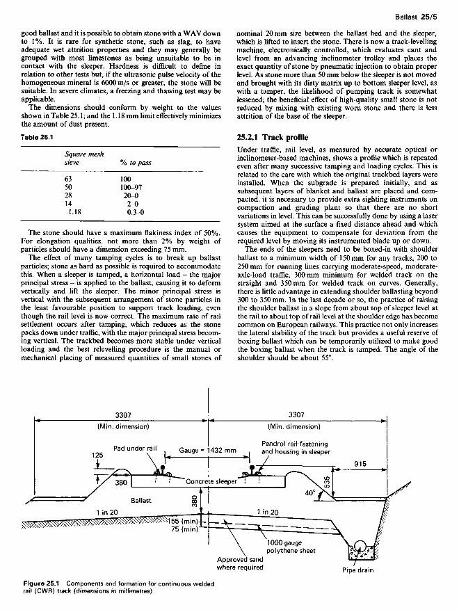
The ends of the sleepers need to be boxed-in with shoulderballast to a minimum width of 150 mm for any tracks, 200 to250 mm for running lines carrying moderate-speed, moderate-axle-load traffic, 300mm minimum for welded track on thestraight and 350mm for welded track on curves. Generally,there is little advantage in extending shoulder ballasting beyond300 to 350 mm. In the last decade or so, the practice of raisingthe shoulder ballast in a slope from about top of sleeper level atthe rail to about top of rail level at the shoulder edge has becomecommon on European railways. This practice not only increasesthe lateral stability of the track but provides a useful reserve ofboxing ballast which can be temporarily utilized to make goodthe boxing ballast when the track is tamped. The angle of theshoulder should be about 55°.
Figure 25.1 Components and formation for continuous weldedrail (CWR) track (dimensions in millimetres)
(Min. dimension)
Pandrol rail fasteningand housing in sleeperGauge= 1432 mmPad under rail
(Min. dimension)
Concrete sleeper
1000-gaugepolythene sheet
Approved sandwhere required
Ballast
Pipe drain
25.3 Sleepers
25.3.1 Timber sleepers and sleeper spacing
The traditional track support since the early days of railwayshas been the timber sleeper, but now prestressed concretesleepers are in use in many countries. In some countries thebaseplated timber sleeper is already more expensive to installthan a baseplateless prestressed concrete sleeper.
In Britain, the sleepers and point and crossing timbers havetraditionally been of softwood, chiefly douglas fir from Canada,Maritime pine from southwest France and Corsica, and Balticredwood from Poland and Russia. Homegrown fir sleepers havebeen used when they have been available. In continental Eur-ope, beech and oak sleepers have been widely used. All soft-wood sleepers, and most hardwood sleepers that can be impreg-nated, are pressure creosoted by the Bethell or Ruping processesbefore being baseplated. The harder softwood sleepers such asdouglas fir or scots fir and hardwood sleepers need to be incisedprior to creosoting. Four to 14 litres of creosote per sleeper is anormal absorption, according to species. In Canada, the US andSouth America a mixture of mineral oil and creosote is used.
A timber sleeper may have a first or running line life ofbetween 6 and 50 years with an average of about 20 yearsaccording to traffic loading, weather exposure, the nature andincidence of the indigenous vegetative and insect enemies oftimber, the presence or absence of baseplates, the nature of thefastenings, the quality of the ballast and its maintenance, thespecies of timber and, significantly, the rate at which it hasgrown.
The British softwood timber sleeper is 250 x 125 x 2600mmwith switch and crossing timbers of 30Ox 150mm section. InEurope, hardwood sleepers mainly of oak or beech are usedwith a depth of 160mm. Sleeper spacing in Britain is 700mmwith 650mm on curves or on timber sleepered continuouswelded rail (CWR). In countries other than Britain, timbersleeper spacings of 600 mm are common with some as close as550 mm in heavy-axle situations.
The sleeper spacing applied represents a compromise betweenoverall sleeper cost and the lessened frequency of maintenanceattention and reduced rail bending stress which results there-from. In addition, a decrease in sleeper spacing may be appro-priate where the formation is weak or where it is not practicableto increase the total track construction depth by increasing thedepth of ballast. Since also increasing the density of sleeperingincreases both the lateral and vertical resistances to bucklingmovements of the track, it is general practice to reduce sleeperspacing when laying track intended to carry long welded rails.Where the rail formation is regularly subjected to frost heavedistortions, there may be a case for deliberately choosing arather weak rail with complementary close sleeper spacing inorder to allow the track to accommodate itself to a frost heavecontour without imposing undue bending stresses in the rails.
25.3.2 Steel sleepers
Steel sleepers are widely used in India, Africa, South America,Asia and in parts of Europe. Steel shortages during andfollowing the Second World War, and the increased use ofconcrete, impeded the further development of steel sleepers untilabout the mid 1970s. Since then, there has been a considerableamount of research done in Australia, Europe, Japan andBritain to evolve improved steel sleeper designs. Computer-based design techniques, e.g. finite element analysis, andmodern stress measuring and analysis techniques have beenapplied to both full-scale laboratory loading and fatigue testing
and to in-track service trials in order to prove the efficacy of newsteel sleeper designs.
Many of the older steel sleeper designs gave average servicelives of over 50 years before failing through cracking in, oradjacent to, the rail seat area. Generally, these cracks propa-gated from rail fastener holes or slots or from discontinuities inthe rail seat area. Abrasive wear and/or corrosion in this areaalso contributed ultimately to sleeper failure. The steel sleeperdesign features, and especially those associated with the railfastener mountings, together with the accumulated gross traffictonnage carried, are the most important factors determiningsteel sleeper life. Recently improved steel sleeper designs havegiven due cognizance to these influences.
It is commonplace to recondition old steel sleepers whichhave already given a 30- to 50-year 'first life', by welding-onsuitably designed reconditioning plates. If required, the recondi-tioning plates used may permit a change in rail fastener type orrail section to be made for the further 'second life' of the steelsleeper. When damaged in service, e.g. by derailments, steelsleepers can readily be repaired by pressing and/or welding.
Steel sleepers do not burn or suffer from exposure to dry heat.In tropical climates their immunity to insect or fungoidaldamage is extremely beneficial.
Loss of metal section through corrosion is usually surpris-ingly low, but there may be a few very special sites subject tosevere corrosion, where the use of steel sleepers would beinadvisable. Under-design of the rail seat, or inadequate sup-port thereof, can greatly increase the localized corrosion andfatigue damage in this generally highly stressed area, and dueallowances have been made in modern designs.
Steel sleepers pack neatly into bundles and thus simplify allhandling and transport operations and greatly reduce thesecosts. The relatively low mass and convenient and uniformshape of steel sleepers is of benefit in both mechanical andmanual handling.
The use of steel sleepers provides good resistance to lateraland longitudinal movement of the track and gives high consist-ency of gauge, both at installation and during subsequentservice. The achievement of good alignment is necessary whensteel sleepers are initially installed and when retamping after abrief 'running in' period. The additional care and attention atthis early stage generally results in a reduced need for subse-quent maintenance, realignment and retamping. Some of theolder steel sleeper designs were difficult to install and adjust, butmodern designs are now relatively easy to install and to use for'spot replacements'.
The inverted trough shape and its entrapment of tamped-upballast provides many benefits. The natural resistance of theballast is more effectively utilized by steel sleepers, and ballastdepth may be decreased by 75 to 100mm as compared withwood or concrete sleepers. This can be of distinct advantage intunnels with limited clearances and ballast depth. Where stan-dard ballast depth is retained, the additional load-spreadingeffect of steel sleepers and their ballast-filled inverted trough,may enable sleeper spacing to be slightly increased. Also, theinverted trough shape has the in-built benefit that any enforcedmovement of the sleeper increases the entrapped ballast densityand its resistance to further sleeper movement, in comparisonwith the solid shape of wood and concrete sleepers whereeventually a 'break-free' point is reached.
Steel sleepers are similar to concrete in their tendency todegrade soft ballast more rapidly than wooden sleepers. Hence,the use of a hard stone is preferred for steel sleepers. Neverthe-less, many old steel sleepers have given long and satisfactoryservice utilizing a gravel-type ballast.
Insulating pads, fastener shoes and/or washers must beincorporated in the steel sleepers designed for lines using trackcircuit signalling. In most cases the insulating components used
are identical to those used with concrete sleepers. Modernplastic materials have improved the electrical security of theseinsulating components and the track circuits, but the highelectrical conductivity of steel sleepers requires special attentionto their design and maintenance.
The mass of individual steel sleepers is usually mid-waybetween that of wood and concrete, and may be considered adisadvantage with respect to resistance to the vertical bucklingof continuously welded rail track. However, the entrappedballast in the inverted trough of steel sleepers and their generalshape (particularly the newer designs) greatly increases the'effective in-track mass' of steel-sleepered track.
Most rail fastener types can be accommodated in steel sleeperdesigns, and there are only isolated fastener systems whichcannot be economically incorporated in steel sleeper designs.
25.3.3 Concrete sleepers
The first experiments with reinforced concrete sleepers weremade over 100 years ago. Concrete is attractively resistant todecay, insect attack and fire, but it is brittle, and reinforcedconcrete sleepers would not withstand the impact loads in mainline track. A solution developed in France in the 1920s was touse pairs of reinforced concrete blocks connected by steel tiebars. This twin-block sleeper continues in use notably in France,Spain and North Africa but is of declining importance world-wide.
Under the pressures of timber shortages during the SecondWorld War, a satisfactory monoblock concrete sleeper wasdeveloped in Britain in 1943 using the then new technique ofpretensioned, prestressed concrete. This has led to a majorindustry in Britain (over 30 million pretensioned concretesleepers have been supplied to British Rail) and many othercountries (notably Norway, Sweden, USSR, Hungary, Czecho-slovakia, Iraq, Japan, South Africa, Australia, Canada and theUS).
In Britain and most of the other countries pretensionedconcrete sleepers are made by the long-line method in which thetendons are fully bonded. This gives good distribution andcontrol of prestress. Post-tensioned sleepers were developed inWest Germany in the 1950s and have found limited favour (inWest Germany, Italy, Spain and Mexico).
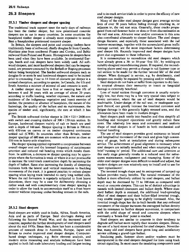
The current British Rail standard sleeper designated F27BS,is prestressed with six 9.3 mm, seven-wire strands (Figure 25.2).It is 2.515 m long, 203 mm deep under the rail, 264 mm wide atthe base and weighs 280kg. For more arduous conditions, astronger version F27AS has been introduced, prestressed witheight strands in the same concrete envelope as the F27BS.Recently the F40, a 2.480 m long sleeper, has been developed tofacilitate single-line mechanized track renewal within the tightBritish Rail structure gauge. The base width is increased to285 mm to maintain the bearing area and the depth is 200 mmunder the rail which gives the same weight as the F27BS.Prestressing is by six strands.
Spacing in British track is usually 700 or 650 mm, although600 mm spacing is used in severe curves.
In the past 15 years, concrete sleepers have gained widerinternational acceptance for several reasons, including:
(1) Higher passenger train speeds and heavier freight axle loadsnecessitate higher quality and stronger track.
(2) High labour costs and intensive track use necessitatereduced frequency of maintenance cycles.
(3) Increased use of mechanized track-laying and renewalequipment has overcome the difficulty of handling heavyconcrete sleepers.
(4) Softwood sleepers are often unable to withstand the stressesin modern main-line track and good-quality hardwood isincreasingly expensive and difficult to obtain.
(5) With modern fastenings, only a resilient pad is requiredbetween the rail and sleeper thereby eliminating expensivebase plates.
It is generally predicted that prestressed concrete sleepers willhave an average life of 40 to 50 years. Some of the earlier designsof concrete sleepers have been removed from the track due topremature failure of the fastenings although the concrete re-mains structurally sound. Since 1964, British Rail have used thePandrol fastening in which the less durable components can berenewed (Figure 25.3). At high speeds (over HOkm/h) wheeland rail surface defects can cause high stresses in concretesleepers which, if allowed to persist, can cause cracking in therail seat area of sleepers. Prestressed sleepers with such crackscan remain serviceable, providing the cause of high stress ispromptly detected and rectified as necessary.
The brittle nature of concrete sometimes gives cause forconcern in derailment damage. In practice, the enhanced stabi-lity of concrete-sleepered track reduces the incidence of derail-ments and their severity is reduced by modern fastenings whichhold gauge well during derailments. Well-filled ballast cribsprovide protection to the concrete and derailment damage to thetrack is not a significant problem with monoblock concretesleepers. Twinblock sleepers, however, perform badly as the tiebarls relatively easily bent causing severe gauge narrowing.
Whilst concrete is a semiconductor, adequate insulation fortrack circuits can be obtained simply and cheaply by incorporat-ing insulating components into the fastening.
Concrete sleepers can be cast into a concrete slab to provideballastless track but it is advisable to use sleepers with projectingreinforcement to ensure permanent connection to the in situconcrete. In dry locations, especially tunnels under sensitivebuildings where structure-borne vibration is objectionable,attenuation can be achieved by enclosing the sleepers partially(without projecting reinforcement) in rubber boots before cast-ing into the slab.
Pretensioned concrete beams have been in use in Britain asswitch and crossing bearers since the early 1970s. Use wasinhibited by the practice of drilling the concrete to locate railfastenings, but manufacturers have now developed methods ofcasting fastenings into the bearers, and increasing use is antici-pated internationally.
Figure 25.2 British Rail F27 prestressed concrete sleeper(Courtesy: Costain Concrete Co. Ltd)
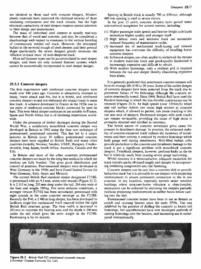
Figure 25.3 Types of rail fastening: (a) spring spike, (b) Pandrolfastening, (c) K fastening, (d) square-section cut spikes, (e) FISTfastening
25.4 Fastenings
Rail fastenings are divided into two categories: direct andindirect. These are further divided into elastic and rigid. Directfastenings are those which fasten the rail directly to the sleeper,and indirect are those which fasten the rail to a chair orbaseplate, which is fastened to the sleeper separately.
Both types of fastenings may be either elastic or rigid,depending on whether a spring element is incorporated, and alsodepending on whether they are adjustable or self-tensioning.
The square-section cut spike was the original fastening usedfor flat bottom rail (Figure 25.3), but in Europe it is no longerused except in sidings and light, narrow-gauge railways. InNorth America, however, and on American-built railways invarious parts of the world, it is still in general use on linescarrying axle loads of up to 351. Resilient forms of the cut spikehave, however, been used extensively outside Canada and theUS, particularly in Europe.
The cut spike has a number of disadvantages which have ledto the decline in its use by European railways. The majordisadvantages are: (1) short sleeper life due to spike killing andbaseplate cutting; (2) the need for high sleepering density (inAmerica timber sleeper spacing of 500 mm is still regarded asnormal); (3) the need for rail anchors either side of the sleeperwith heavy-section rail; and (4) variable track gauge. The cutspike is a simple and robust system which lent itself well to rapidpioneer developments, but it is poorly suited to high speeds andwelded rail, especially in countries where temperatures varybetween extremes of heat and cold. It is also of little use incountries where timber is not readily available.
In Europe, the coachscrew direct fastening has been preferredand is still used extensively. Both cut spike and coachscrew havepoor gauge-holding when used as direct fastenings, but whenused with baseplates, their performance is improved and thiscan be improved further when additional screws or spikes areused to secure the baseplate to the sleeper. It is now generalpractice to fit baseplates on all curved track fastened with spikesor screws.
The main advantage of the screw over the cut spike is that itexerts a positive pressure on the rail foot whereas the spikeallows the rail to float 'free'. It therefore goes some way towardresisting rail creep and rail expansion due to temperaturechange. In France and on French-built railways, the generallyaccepted standard fastening is a combination of the screw spikeused with a spring clip (called the RN fastening).
In Germany and much of Central Europe, the K fastening ofthe Deutsche Bundesbahn has been the standard fastening since1926. It consists of a rolled steel baseplate giving a 1:40 railinclination with two heavy ribs forming a channel seating for therail resting on a 5 mm compressed poplar or plastic pad andslotted to take a T-headed bolt each side, inverted rigid U-shaped clips being held by the T bolts to which heavy springwashers are fitted. Four screws are used to hold the baseplatedown to timber sleepers in Germany but, in some other coun-tries, e.g. Belgium, only two are used. In Germany, spring steelwashers are commonly used on baseplate screws. A number ofspring clips have been developed which can be driven into therib of the baseplate to replace the rigid clips.
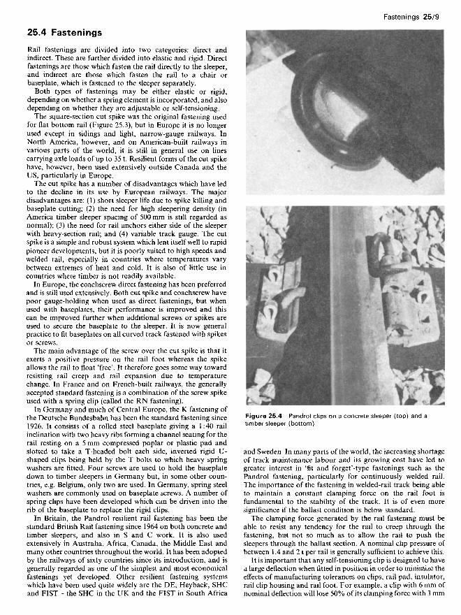
In Britain, the Pandrol resilient rail fastening has been thestandard British Rail fastening since 1964 on both concrete andtimber sleepers, and also in S and C work. It is also usedextensively in Australia, Africa, Canada, the Middle East andmany other countries throughout the world. It has been adoptedby the railways of sixty countries since its introduction, and isgenerally regarded as one of the simplest and most economicalfastenings yet developed. Other resilient fastening systemswhich have been used quite widely are the DE, Heyback, SHCand FIST - the SHC in the UK and the FIST in South Africa
Figure 25.4 Pandrol clips on a concrete sleeper (top) and atimber sleeper (bottom)
and Sweden. In many parts of the world, the increasing shortageof track maintenance labour and its growing cost have led togreater interest in 'fit and forget'-type fastenings such as thePandrol fastening, particularly for continuously welded rail.The importance of the fastening in welded-rail track being ableto maintain a constant clamping force on the rail foot isfundamental to the stability of the track. It is of even moresignificance if the ballast condition is below standard.
The clamping force generated by the rail fastening must beable to resist any tendency for the rail to creep through thefastening, but not so much as to allow the rail to push thesleepers through the ballast section. A nominal clip pressure ofbetween 1.4 and 21 per rail is generally sufficient to achieve this.
It is important that any self-tensioning clip is designed to havea large deflection when fitted in position in order to minimize theeffects of manufacturing tolerances on clips, rail pad, insulator,rail clip housing and rail foot. For example, a clip with 6 mm ofnominal deflection will lose 50% of its clamping force with 3 mm
of wear or tolerances, whereas with 12 mm of deflection, the toeload loss will be only 25%. The ability to ensure positive andaccurate track gauge retention is also an important feature of arail fastening.
Resilient rail fastenings are now used in the harshest ofoperating conditions, such as heavy haul and high-speed pas-senger services, and particular attention is being devoted toimproving the ability of fastening assemblies to attenuate thetransmission of dynamic forces from rail to sleeper. This isproving to be of particular importance in the case of fasteningsused with concrete sleepers in high-speed passenger operations.Considerable effort is being focused on improving rail padcharacteristics.
A further area of development in rail fastenings is the need formechanical installation in those areas of the world where tracklabour costs are relatively high, and machines are now availableto drive some of the more widely-used fastening types.
25.5 Rails
The flat bottom, or Vignole, rail is now an almost universalstandard so that the obsolescent bull head rail of past Britishpractice need not be developed here.
Generally, rail sections or weights are derived from progres-sive experience, not because of analytical difficulties but becauseof inadequate quantified knowledge of what conditions ofloading and support actually occur.
A simple rough guide to appropriate rail weight in kilogramsper metre is to multiply the axle load in tonnes by 2. However, itis necessary to make allowance for a speed factor and thefollowing formula given by Schramm does this:
Rail weight in kilograms per metre = 156 - (25.1)
where A = static axle load in tonnes and a = the speed factor.The speed factor is still under critical review but it can beevaluated by three equations which are widely accepted forpractical use:
a = 1 + (J^/30 000) up to 100 km/h (25.2)
a = 1+(4.5FVlO5)-(1.5FVlO7) upto l40km/h (25.3)
a=1.18 + (0.706^/107) over 140 km/h (25.4)
From the above expressions, Table 25.2 has been produced. Thefigures give an indication of appropriate weights within ± 15%.
British Standard specifications include rails from 25 to56.5kg/m; in Europe rails up to 60kg/m are used and up to70 kg/m in the US.
Table 25.2 Approximate rail weights, in kilograms per metre
Static Speedaxle (km/h)weight(t) 50 100 140 160 200
15 28 34 36 37 3920 36 42 44 46 4925 44 50 52 54 5830 50 56 59 61 6535 57 61 65 67 70
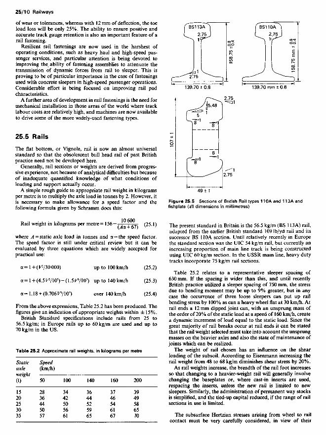
Figure 25.5 Sections of British Rail types 110A and 113A andfishplate (all dimensions in millimetres)
The present standard in Britain is the 56.5 kg/m (BS 113A) rail,adapted from the earlier British standard 109 Ib/yd rail and itssuccessor BS UOA section. Until relatively recently in Europethe standard section was the UIC 54 kg/m rail, but currently anincreasing proportion of main line track is being constructedusing UIC 60 kg/m section. In the USSR main line, heavy dutytracks incorporate 75 kg/m rail sections.
Table 25.2 relates to a representative sleeper spacing of630 mm. If the spacing is wider than this, and until recentlyBritish practice utilized a sleeper spacing of 750 mm, the stressdue to bending moment may be up to 9% greater, but in anycase the occurrence of three loose sleepers can put up railbending stress by 100% as can a heavy wheel flat at 30 km/h. Atrail ends a 12mm dipped joint can, with an unsprung mass ofthe order of 20% of the static load at a speed of 160 km/h, createa dynamic increment of load equal to the static load. Since thegreat majority of rail breaks occur at rail ends it can be statedthat the rail weight selected must take into account the unsprungmasses on the heavier axles and also the state of maintenance ofjoints which can be realized.
The weight of rail chosen has an influence on the shearloading of the subsoil. According to Eisenmann increasing therail weight from 48 to 68 kg/m diminishes shear stress by 20%.
As rail weights increase, the breadth of the rail foot increasesso that changing to a heavier-weight rail will generally involvechanging the baseplates or, where cast-in inserts are used,respacing the inserts, unless the new rail is limited to newsleepers. Similarly, the administration of permanent way stocksis simplified, and the tied-up capital reduced, if the range of railsections in use is limited.
The subsurface Hertzian stresses arising from wheel to railcontact must be very carefully considered, in view of their
relationship with wheel load, wheel size and tensile strength ofthe rail steel. The Hertzian contact stresses are directly related tothe square root of the wheel load and inversely related to thesquare root of the wheel radius. The nominal shape of the railhead and wheel tread profiles and the progressive wear of thesetwo profiles in service, also influence the actual wheel-railcontact area and, hence, the Hertzian contact stresses. Themaximum level of the Hertzian contact stress normally occurs afew millimetres below the contacting surfaces, and shelling andsimilar subsurface fatigue failures can develop if the shear stressin this contact zone exceeds about 50% of the ultimate tensilestrength of the rail steel. Under conditions of excessive stressing,complete collapse of the rail head can occur.
The principal rail specifications in international use are BSl 1of the British Standards Institution, UIC 860-0 of the UnionInternationale des Chemins de Per (UIC) and the Manual of theAmerican Railway Engineering Association (AREA). A normfor railway rails (ISO 5003) has also been published by theInternational Standards Organization (ISO).
The most commonly used rail steels are defined in the abovestandard specifications and can be classified as follows:
(1) Normal grades, typically of 680N/mm2 minimum UTS asper BS 11 normal grade and UIC 860-0 grade 70.
(2) Wear resisting grades, typically of 880N/mm2 minimumUTS as per BS 11 wear resisting grades A and B, UIC 860grades 9OA and 9OB, AREA standard carbon grade.
(3) Premium high strength grade, typically of 1080N/mm2
minimum UTS.
The premium high-strength rail grades are still the subject ofmuch research and development, and are briefly referred to inonly one specification - AREA.
These premium grade rails are produced either by the use ofalloy steels, generally about 1% chromium and in some caseswith micro-alloying additions of vanadium, molybdenum orniobium, or by the heat treatment of wear-resisting grade rails,e.g. BS wear resisting grade A, UIC 860 grade 9OA, or AREAstandard carbon grade. The heat treatment may consist of eitherfull section hardening or localized head hardening only.
The rail steel grade selected for a particular track is dependenton various factors including track design, traffic and operatingconditions, standards of maintenance and economic factors, etc.
Table 25.3 illustrates the different optimum strategies selectedby different railroads. It is common practice to utilize a higher-strength, more wear-resistant, rail steel grade in tight curves,and a less expensive grade in straight track.
Broad recommendations for the selection of rail steel gradebased on track curvature and traffic intensity are outlined inUIC Code 721-R.
A special grade of rail steel utilized throughout the world,albeit in relatively small quantities, is austenitic manganese steel(12-16% Mn) which is usually used in heavily trafficked tur-nouts, switches and crossings. Many crossing vees (frogs) areproduced as austenitic manganese castings. Rolled austeniticmanganese rails are produced in Britain in relatively smallquantities being used in the fabrication of turnouts and S and Cwork, and occasionally in curved track. Austenitic manganese
steel surface hardens rapidly in service under stress and impact,and develops high wear resistance. However, it is expensive,needs great care in machining to avoid the risk of fatigue crackinitiation and can only be welded to similar steel by normal railwelding techniques. Its higher thermal coefficient of linearexpansion also produces manufacturing problems and serviceuse limitations, but rolled austenitic manganese rails have beensuccessfully welded and used in the relatively constant tempera-ture conditions of underground railways.
Experimental work continues in the evaluation of more exoticand expensive rail steel chemistries for special applications, e.g.bainitic steels.
Rail joints are either suspended or supported. Joints are alsosquare, i.e. opposite each other, or staggered by up to half therail length. In some administrations, rail joints are square on thestraight and staggered on the curves. Rail and fishplate sectionsneed to be considered together in selecting a rail section, since ifthe ratio of the Ixx of the fishplate is much below 25% of the /rxof the rail, broken fishplates and battered rail ends are likely tohave a high incidence.
25.5.1 Rail failures
It is necessary in any railway system that a record should be keptof all cracked and broken rails removed from the track. Inaddition, the cause of failure must be noted in order to monitorany specific problems which may be developing. This is carriedout with the use of a standard reporting form which gives detailsof track and conditions as well as the type of defect. Thisinformation is fed into a computer and frequent monitoring ofthe data gives any developing trends.
Whilst this latter information gives details of rails removed, itdoes not give any indication of those defects remaining in thetrack under observation. This information comes from thenormal regular examination of the track which is carried out bymeans of an ultrasonic rail flaw detection train and also byhand-held ultrasonic rail flaw detectors used by pedestrianoperators.
The ultrasonic test train is normally a self-propelled unitconsisting of two vehicles. It operates at speeds up to 30 km/hand uses a series of probes which are applied to the rail headeither in the form of sliding probes or wheel probes. The datafrom these probes are partially reduced by an on-board com-puter and the resulting information is stored on magnetic tapefor subsequent off-line analysis. The defects detected by thissystem are sent to the appropriate maintenance engineers foraction depending on the type of defect.
In addition to the train, hand-held ultrasonic units are used tocarry out work in areas not covered by the test train and also toexamine, in greater detail, defects which have been picked up bythe test train but which require more detailed study. In addition,the hand units are also used for monitoring defects which areallowed to remain in track until such time as they can berepaired or removed.
Ultrasonic testing of rails is carried out at a frequencydetermined by the types and speeds of traffic carried. It ranges
Table 25.3
Country
BritainEuropeUS
Max. axle load(t)
2622.528
Rail section(kg/m)
56.46068
Max. speed(km/h)
2002001 20-1 30
Straight track
NormalWear- resist.Wear- resist.
Rail steel grade usedCurves
Wear-resist.PremiumPremium
from 6 months to alternate years for some of the lightly usedbranch lines.
In addition to this routine testing, other specialized tests arecarried out by both the test train and the hand operators whichinclude gauge measurement, crack size estimation in specialcases and weld testing.
25.6 Curved track
The main curves of the railway are nominally of constant radius,i.e. circular curves; curves made up of two or more circularcurves of different radii curving in the same direction are calledcompound curves. Straights are generally and desirably con-nected to circular curves by transition curves of progressivelyvarying radii; and adjoining circular curves of different radii arecommonly joined together in a similar way if the difference ofradii exceeds about 10%. Two adjoining circular curves curvingin opposite directions comprise a reverse curve, and here,whatever the radius, the presence of connecting transitions isrelatively more important than with circular or compoundcurves.
For practical purposes the cubic parabola y = kx* gives auniform change of curvature between tangent point on thestraight and tangent point on the curve, or between the tangentpoints of two curves, and is the most used form of transitioncurve. The versines, measured on half-chord overlapping chordsalong the transition, change with linear uniformity from zero toR although it is usual to smooth out the rate of increase anddecrease at the start and end of the transition by putting onabout one-sixth of the rate of the first versine at the zero stationand reduce the increment at the final transition station to aboutfive-sixths of the half-chord rate of increase. Versines areconveniently measured in millimetres.
The geometrical relation between a circular curve and atransition curve tangenting on to both the straight and thecircular curve involves the moving inwards along a diameternormal to the straight of the circular curve by an amount termedthe 'shift'. The transition curve bisects the shift at its midpointmeasured along the straight tangent line and the offset from thatline to the tangent point of the transition and circular curve is 4times the shift or 8 times the offset at the mid-transition point. Itfollows that where no transition exists or where it is insufficientin length the institution or extension of a transition can be doneonly by sharpening the radius of the circular curve concerned ormoving the tangent straight away from the curve, though thismay be worthwhile since any transition is better than none.
The length of a transition curve is determined primarily bywhat is judged to be an acceptable rate of change of cant or cantdeficiency. For standard gauge plain track a desirable rate maybe 35 mm/s, with a maximum of, say, 55 mm/s to securepassenger comfort. In switches and crossings a rate as high as80 mm/s may be applied but a good standard of switch and leaddesign is desirable for this rate of loss or gain of cant or cantdeficiency.
Some limiting cant and cant deficiency values observed inBritish practice on a 1.432m gauge are listed at top right.
Wherever space permits, curve design should be based on thedesirable rate of change of cant or deficiency of 35 mm/s.
The amount of cant applied to a track depends upon con-sideration of the following factors:
(1) The line speed limit, i.e. the maximum speed at which trafficis allowed to run on a line or branch or section of a line orbranch. This limit is usually fixed with reference to the valueand distribution of permanent speed restrictions on the lineor branch, or section thereof, involved.
(2) The proximity of permanent speed restrictions, junctions,stopping places, etc.
(3) Track gradients which may cause a reduction in the speed offreight or slow-moving passenger trains without having anappreciable effect on the speed of fast trains.
(4) The relative importance of the various types of traffic.
Generally, where fast and slow trains run on the same lines,an intermediate speed is selected to fix the cant. In this situationit may exceptionally be necessary to limit the cant and thereforethe maximum speed to prevent surface damage to the low rail byheavy axles on slow-moving freight trains.
Each line of a double line should be separately assessed. Inexposed locations subject to high winds it may be desirable tolimit cant to below the 150 mm maximum.
Normally, cant or cant deficiency is uniformly gained or lostwithin the length of a transition curve or, where there is notransition curve, as may occur in switches and crossings, overthe length of the virtual transition, which for practical purposesis taken as the shortest distance between the centres of bogies ofcoaching stock using the line. If the desired cant cannot be puton within this length observing a maximum cant gradient of 1 in400, the cant loss or gain is continued on to the circular curve.The 1 in 400 cant gradient mentioned relates to axle twistderailment possibilities, especially where four-wheeled vehiclesare concerned.
The maximum permissible speed on circular curves appropri-ate to the determination of permanent speed restrictions may,for standard gauge railways, be obtained from the followingexpressions:
Equilibrium (or theoretical) cant = E= ll.S2(Ve2/R)mm
Equilibrium speed= Ve = Q.29J(RE)km/h
Maximum speed = Vm = Q.29JR (E+ D) km/h
where R = radius in metres, E=cant, which may be either actualcant or equilibrium cant but in practice the difference is not
Maximum cant:on curved trackat station platformsmaximum cant gradientdeficiency on plain line, CWRdeficiency on plain line, jointed trackdeficiency on switches and crossings weldedinto CWR
on through lineon turnoutwith negative cant on turnoutat switch toes
deficiency on switches and crossings injointed track
on through lineon turnoutwith negative cant on turnoutat switch toes
Maximum rate of change of canton plain lineon switches and crossings
Maximum rate of change of cant deficiencyon plain lineon switches and crossings
Maximum rate of change of cant deficiencyon plain lineon switches and crossings (inclined design)on switches and crossings (vertical design)
150mm110mm1 in 400110mm90 mm
110mm90 mm90 mm125mm
90 mm90 mm90 mm125mm
55 mm/s55 mm/s
55 mm/s55 mm/s
55 mm/s55 mm/s80 mm/s
likely to be significant, though the distinction has to be kept inmind in certain circumstances, and D = maximum allowablecant deficiency in millimetres.
Desirable lengths of transition curves can be derived from thegreater of the two values obtained from:
Length = L = Q Wl 5EVm mor L = 0.0075/) Vm m
where £=cant in millimetres, D = deficiency of cant in milli-metres and Vm = maximum permissible speed in kilometres perhour.
If space is limited, the length of the transition may be reduced totwo-thirds L subject to a minimum cant or cant deficiencygradient of 1 in 400.
On compound curves to be traversed at a uniform speed, thedesirable length is obtained from the greater of the two follow-ing expressions:
L = 0.0075(JE1, - E2) Vm m orL = 0.0075(Z)1 -D2) Vm m
where £", and Z)1 are the cant and cant deficiency conditions forone curve and E2 and D2 are the similar values for the othercurve.
Similarly, on reverse curves the transition lengths are givenby:
L = 0.0075(£, + E2) Vm m orL = 0.0075(Z)1 + D2) Vm m
It should be noted that in using the above formulae theconstants used have reference to a standard gauge, to anassumed height of the centre of gravity of vehicles of about1.5m and a subjective passenger comfort assessment of thetolerable rate of change of cant or cant deficiency. To this extentthe values are arbitrary rather than absolute and refer tostandard gauge. Further qualifications are that the springing ofvehicles may be such as to produce excessive lean under cantdeficiency running to encroach significantly on side clearancesor to diminish passenger comfort, whilst if the centre of gravityof a vehicle is higher or lower than that assumed the maximumpermissible speed is affected in inverse ratio, so that certainvehicles may be permitted to run at a higher speed than othervehicles.
The versine or middle ordinate of a chord on to a curve isproportional to the curvature and is the basis of all railwaycurve alignment, checking and adjustment. Its value as deter-mined from triangular analysis is given by:
2R = {(C/2f/V}+V (25.5)
where R = radius of a curve, C= length of chord on which theversine is measured, and V= the versine, but since the value of Vis very small in relation to R in railway situations, the final V ofthe expression may be disregarded so that for both fieldmeasurements and calculation purposes:
V=C2IZR (25.6)
In Britain and on the Continent, railway curvature is usuallydescribed by the length of the radius measured in metres. TheAmerican practice is to describe a curve by the angle subtendedat the centre of the curve by a chord of 30.48 m. For railwaywork it is sufficient in transposing degree units into radius unitsto divide 1746 by the degree of the curve to give the radius in
metres. Thus, what is described in American practice as a 10°curve would be described in Europe as a curve of 175 m radius.
Main railway curves are initially set out by theodolite gener-ally on the basis that equal chords are subtended by equal anglesbut informal setting out by an offset from a tangent followed bythe use of overlapping chords of convenient length using theversine appropriate to the radius can give a degree of accuracysufficient for less important curves. A selection of curve formu-lae covering most calculations for the design or setting out ofrailway circular curves is set out in Table 25.4.
It is desirable to keep rail joints more or less square, or at aconstant stagger where this is preferred, on curves by insertingshort rails in the inner rail of curved track. The difference in raillength, D, for standard gauge and for 18.3m rails is given byZ) = (27.45/radius in metres) m. Alternatively, the approximatedifference in length can be obtained from the formula D = § ver-sine. It is normal to take a standard range of short rails from themakers and for 18.3 m rails, these are 18.25, 18.20 and 18.15 m.
The precise alignment of curves is vital to a smooth ride,stability of the track geometry and minimizing track wear.There are several alternative methods of adjusting railwaycurves as a maintenance operation but all are based on versinemeasurements and relate, either to a smoothing or averagingapproach, in which the differences between a limited number ofadjacent versines are adjusted to give a fairly uniform rate ofchange in transitions or to a fairly uniform value on circularcurves; or to a design lining approach in which the whole of theversines of a curve are adjusted as one revision operation to givea precise rate of increase or decrease in transitions and a strictlyuniform value on the circular curve portion, as far as clearancesfrom structures, etc. will permit. It is generally convenient to usesmoothing or local adjustment techniques after a curve has beenaligned on a design basis. It is also normal practice to setmarkers or monuments or pegs in or beside the tracks whendesign lining is carried out.
Curve realignment can be based on manual measurement ofversines or with less accuracy on the versine measurements of atrack geometry recording car or of a track lining machine.
The side and interbody clearances shown on the diagramcontained in the Department's Requirements (see Figure 25.15)relate to straight track and may need to be augmented on curvedtrack for end throw or centre throw of vehicles, which aregenerally of the same magnitude.
Centre throw= C= B2/ZR
End throw = E=(L2- B2)/8R
where B = wheelbase or bogie centres, L = length of vehicle, andR = radius.
To this increase of effective body width on curved track must beadded a further allowance due to the tilting of the vehicle to thelow side on canted track. In Britain, the loss of side clearance atthe vehicle cornice is about 2.25 times the actual cant.
It is general practice slightly to widen the track on very sharpcurves to allow all vehicles, especially locomotives with longrigid wheelbases, to pass round such curves without strainingthe track. The normal British practice is:
Curves over 20Om radius widened to 1435 gauge200 to UOm radius widened to 1439 gauge110 to 70m radius widened to 1451 gauge
Appropriate values of gauge widening for a given track radiusdepend on free play of wheelsets, length of half wheel flangebelow rail level and rigid wheelbase of the critical vehicle.
In the UK it is the Department of Transport's enjoinedpractice to install check rails on curves of 200 m or less radius.
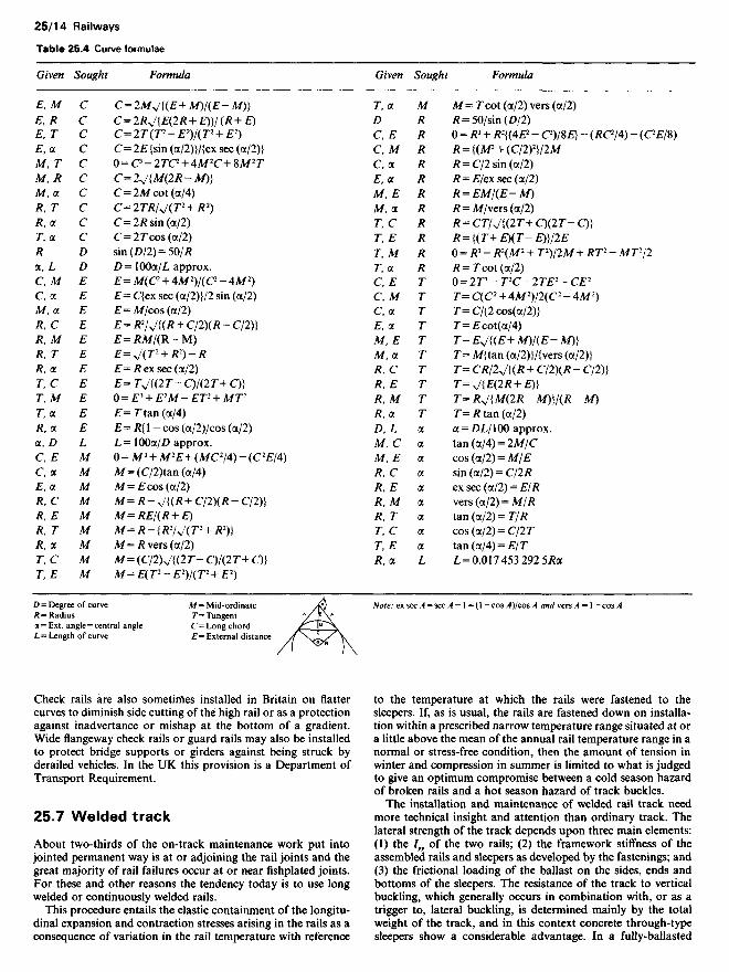
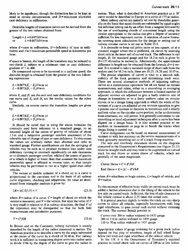
Table 25.4 Curve formulae
Given Sought Formula
E, M C C=2MJ{(E+M)I(E-M)]E, R C C=2RJ[E(2R + £)}/(/? + E)E, T C C=2T(T2-E2)I(T2 + E2)E, (X C C=2E(sin (a/2)}/{ex sec (a/2)}M, T C Q = C-2TC2 + 4M2C+8M2TM, R C C=2J[M(2R-M)}M, (x C C= 2Mcot(oL/4)R, T C C=2TR/J(T2 + R2)R, (X C C= 2R sin (a/2)T, (x C C=2rcos(a/2)R D sin(/)/2) = 50//?a, L Z) D= lOOa/L approx.CA/ £ E= M(C2 + 4M2V(C2 - 4M2)C, a £ £= C{ex sec (a/2)}/2 sin (a/2)A/, a £ £=A//cos(a/2)/?, C £ £= /?2M(# + C/2)(/? - C/2)}R, M E E=RMf(R-M)R, T E E= J(T2+R2)-RR1(X E £=/?exsec(a/2)T, C E E= TJ[(2T- C)I(IT+ C)]T, M E O = £3 +E2M-ET2 +MT2
T1(X E £=rtan(a/4)R, (x E E=R{\-cos(a/2)/cos(a/2)(X, D L L= 10Oa//) approx.C, £ A/ 0=A/3 + A/2£+(A/C2/4)-(C2£/4)Ca M A/=(C/2)tan(a/4)£, a M A/=£ cos (a/2)/?, C A/ A/=/?-V{(/?+C/2)(/?-C/2)}/?, £ M M= REj(R+E)R,T M M= R-[R2I J(T2 +R2)}R ,(X M M= RVQTS (a/2)T, C M M=(C/2)J[(2T-C)/(2T+C)}T, E M M=E(T2-E2)I(T2 + E2)
D = Degree of curve M = Mid-ordinateR - Radius T= Tangenta = Ext. angle = central angle C = Long chordL = Length of curve £ = External distance
Check rails are also sometirftes installed in Britain on flattercurves to diminish side cutting of the high rail or as a protectionagainst inadvertance or mishap at the bottom of a gradient.Wide flangeway check rails or guard rails may also be installedto protect bridge supports or girders against being struck byderailed vehicles. In the UK this provision is a Department ofTransport Requirement.
25.7 Welded track
About two-thirds of the on-track maintenance work put intojointed permanent way is at or adjoining the rail joints and thegreat majority of rail failures occur at or near fishplated joints.For these and other reasons the tendency today is to use longwelded or continuously welded rails.
This procedure entails the elastic containment of the longitu-dinal expansion and contraction stresses arising in the rails as aconsequence of variation in the rail temperature with reference
Given Sought Formula
T, (x M M= T cot (a/2) vers (a/2)D R R = 50fsm(D /2)C £ R O = /?3 + R2{(4& - C*)/8£} - (RC114} - (C2EfS)C1M R R = [(M2 + (C/2)2]/2MC, <x R R= C/2 sin (a/2)E, (x R /? = £/exsec(a/2)A/, £ R R=EMf(E-M)M, (x R /?=A//vers(a/2)T, C R R= CT/J{(2T+ Q(IT- C)]T, E R R = {(T+E)(T-E)]I2ET, M R 0=R*-R2(M2+T2)I2M+RT2-MT2I2T, (x R R= T cot (a/2)C£ T 0 = 2r-T2C-2TE2-CE2
C, M T T= C(C2 + 4M2)/2(C2 - 4M2)C, <x T T= C/{2 cos(a/2)}E, (x T T=£cot(a/4)M, E T T= EJ[(E+ M)I(E- M)]M, a T T= M{tan (a/2)}/{vers (a/2)}R, C T T= CR/2J[(R + C/2)(R - C/2)}R, E T T= J(E(IR +E)]R, M T T= RJ (M(2R-M)]I(R-M)R, (x T T=R tan (a/2)D, L (x (X = DLI1OO approx.M, C (x tan(a/4) = 2A//CM, E (X cos(a/2) = A//£R, C (x sin (a/2) = C/2/?/?, £ a exsec(a/2) = £//?R, M a vers (a/2) = MjRR, T (x tan (a/2) =7/7?T1C (x cos (a/2) = C/2 TT9E (x tan (a/4) = E/7R, a L L = 0.017 453 292 5R(X
Note: ex sec A = sec A - \ = (1 - cos A)/cos A and vers A = 1 - cos A
to the temperature at which the rails were fastened to thesleepers. If, as is usual, the rails are fastened down on installa-tion within a prescribed narrow temperature range situated at ora little above the mean of the annual rail temperature range in anormal or stress-free condition, then the amount of tension inwinter and compression in summer is limited to what is judgedto give an optimum compromise between a cold season hazardof broken rails and a hot season hazard of track buckles.
The installation and maintenance of welded rail track needmore technical insight and attention than ordinary track. Thelateral strength of the track depends upon three main elements:(1) the lyy of the two rails; (2) the framework stiffness of theassembled rails and sleepers as developed by the fastenings; and(3) the frictional loading of the ballast on the sides, ends andbottoms of the sleepers. The resistance of the track to verticalbuckling, which generally occurs in combination with, or as atrigger to, lateral buckling, is determined mainly by the totalweight of the track, and in this context concrete through-typesleepers show a considerable advantage. In a fully-ballasted
track the ballast representatively accounts for about two-thirdsof the total moment of lateral resistance. Loose sleepers andkinks in the alignment are of especial significance to the stabilityof welded track so that a high standard of maintenance isessential for this sort of permanent way.
25.7.1 Fastening welded rails
The need to fasten the rails in order to get a stress-free rail atabout the mean of the annual temperature range would mean, inmany parts of the world, a very short season for laying weldedrails without artificial assistance. This assistance is normallysupplied either by heating the rails by propane gas travellingheaters or by using hydraulic tensors, so that when fasteneddown after extension by heat or tensile pull, the rail has a lengthequivalent to a stress-free condition at a temperature betweenprescribed limits (21 to 270C for the UK). In this way it ispossible to lay welded track all the year round. The pull requiredto extend a 56 kg/m rail is of the order of 1.6 t/°C. The tensorshave a capacity of about 701.
Figure 25.6 Hydraulic rail stresser. This has a 70-t pull and380-mm stroke. For pushing action, the rail clamps are turnedthrough 180°. (Courtesy: Permaquip Co. Ltd)
Welded rails are not normally laid in Europe in curves with alesser radius than 600 m. Long welded rails are made up by flashbutt welding of standard rail lengths into welded rails of 200 to400 m length in depot and welded into continuous welded railsby Thermit welds, except in the USSR where a transportableflash butt welder is applied to join rails in the track.
It is normal practice in Britain and France to install slidingswitches at the ends of long welded rails but in Germany this isnot done, reliance being placed on very firm fastening of thewelded rails where they connect with jointed track.
The advantages of welded track include an extension of raillives by about a third, a reduction of on-track maintenance byabout half, a dramatic reduction of rail breakages, an increase inrunning speeds, less damage to the formation, increased sleeperlives, improved ride comfort, a reduction of traction energy ofup to 5%, and a reduction in train noise. In effect, welded rails,prestressed concrete sleepers and self-tensioning fastenings arecomplementary to each other in extending the life and reducingthe long-term overall cost of permanent way.
25.8 Switches and crossings
All railway switch and crossing work is built up of three basicunits: (1) switches; (2) common or acute (angle) crossings; and(3) obtuse (angle) or diamond crossings. Layouts of switchesand crossings are illustrated in Figures 25.7 to 25.10.
25.8.1 Switches
The heel of a switch is the point from which it is free to move.Early switch designs had a loose heel formed by a semi-tightfishplated joint but this type is now rarely used outside ofsidings. It is now the general practice for the heel of the switch tobe formed by a bolted connection through a block betweenswitchrail and stockrail so that the switch joint is well behind theheel. The length of the switch planing on the bead of the railvaries between about 1.6 and 11 m and most railway administra-tions have a range of two to eight standard switches to meet therequirements of short leads in depots and various speeds oftraffic on the running lines.
Originally, ordinary or straight planing of switch blades wasuniversally applied but during the last few decades curvedplaning, in which the switch rail is bent elastically whilst beingplaned on one side of the head, has become general. In this waythe curve running through the lead is continued to the switchtip. A recent practice is to apply a larger radius to the planing ofthe switch than is applied to the switch beyond the end of theplaning to give a more robust switch tip with a finite entry angle.
25.8.2 Crossings
Crossings are described by the angle at the crossing nose. Incontinental Europe it is common to state this in degrees but overthe English-speaking world the angle is usually described as 1 inN. However, the angle of a crossing expressed as 1 in W variesslightly according to the measuring convention adopted. Thus if1 in 8 is obtained by measuring 8 units along the centreline for 1unit of symmetrical spread normal to the centreline (centrelinemeasure), then measuring 8 units along one leg of the vee for aspread of 1 unit measured at right angles to that leg (right anglemeasure) will give 1 in 7.969, whilst if 8 units is measured alongeach leg to give a spread of 1 unit the crossing size will be 1 in8.016 (isosceles measure). It is therefore necessary for anyrailway to have a specific mode of measuring crossings which isknown to all supplying manufacturers of crossings, or to statethe angle in degrees.
In the UK fixed diamond crossings are limited by Ministryrequirement to be not flatter than 1 in 7.5. In continental Europe1 in 10 is the general limit. Where a line crossing flatter than theallowed limit is necessary, the points of the diamond crossingsare constructed as switches and have to be set to suit the trainmovement desired.
There is no official limit on the angle of common crossings but1 in 28 is about the flattest angle at which the crossing nose hassufficient robustness. Crossings are either made up from rails orare cast in 12 to 14% manganese steel. Built-up crossings havethe inherent limitations of bolted assemblies, and of recent yearsit has become general practice in the UK to weld the vee sectionand Huck-fasten the wings. In general, it is preferred practice tohave cast crossings for high-speed or heavily worked lines usingbuilt-up crossings for less exacting duty. It is also preferred touse cast crossings for angles flatter than about 1 in 20. In the USit is common practice for the nose section of the crossing to be amanganese casting to which ordinary rail section wings areattached to form what is known as a rail bound cast crossing.
![€¦ · Web view[2] If two clusters of missing sleepers are not separated by a cluster of sleepers with at least an equal number plus one of consecutive effective sleepers and](https://img.pdfslide.net/doc/110x75/5e95ffb00fcff126f66cf300/web-view-2-if-two-clusters-of-missing-sleepers-are-not-separated-by-a-cluster.jpg)


![Outback Sleepers Product Brochure Final[2] · Outback Sleepers offer the highest quality concrete retaining wall sleepers and precast panels, engineered to achieve wall heights in](https://img.pdfslide.net/doc/110x75/5e8fc5dc543b38593c3f803b/outback-sleepers-product-brochure-final2-outback-sleepers-offer-the-highest-quality.jpg)