Embed Size (px)
Citation preview

Ralf Koetter, Andrew C. Singer,and Michael Tüchler
apitalizing on the tremendousper formance gains of turbocodes and the turbo decodingalgorithm, turbo equalization is
an iterative equalization and decodingtechnique that can achieve equally impres-sive performance gains for communicationsystems that send digital data over chan-nels that require equalization, i.e., thosethat suffer from intersymbol interference(ISI). In this article, we discuss the turboequalization approach to coded data trans-mission over ISI channels, with an empha-sis on the basic ideas and some of thepractical details. The original system intro-duced by Douillard et al. can be viewed asan extension of the turbo decoding algo-rithm by considering the effect of the ISIchannel as another form of error protec-tion, i.e., as a rate-1 convolutional code.
Background and OrganizationGraphical models for turbo codes (and low-density, parity-check (LDPC) codes), togeth-er with the various iterative algorithms for
C
©IM
AG
ES
TAT
E
IEEE SIGNAL PROCESSING MAGAZINEJANUARY 2004 671053-5888/04/$20.00©2004IEEE

IEEE SIGNAL PROCESSING MAGAZINE68 JANUARY 2004
decoding them, have provided substantial insights into thedramatic performance improvements achievable throughtheir use [1]–[4]. For an overview about graphical models,we also refer to [5]. The flurry of research in related topicsover the last decade has produced a number of communi-cations and signal-processing algorithms that leverageturbo decoding approaches to provide similar gains in per-formance for a wide array of problems [6]–[14]. The orig-inal system introduced in [9] leveraged the ideas of theturbo decoding algorithm to the related problem of equal-ization and decoding. We seek to provide an overview ofthe turbo equalization approach, with an algorithmicdescription and intuitive explanation of each of the stepsinvolved in designing such a communication system.
In the following section, we provide a brief overviewof the turbo equalization approach. Then, we present abasic system model for a coded data transmission sys-tem together with a notional system example. Next,optimal detection strategies are discussed, followed byseparate equalization and decoding methods. Theturbo equalization algorithm is described in moredetail, together with some measures of system perform-ance for our example. Extensions and concludingremarks are presented in the last section.
OverviewIn this section, we provide a high-level overview ofturbo equalization, placing an emphasis on the con-cepts involved and delay a more mathematical develop-ment to subsequent sections of the article. The focus ofour discussion will be the communication link depictedin Figure 1, which contains a system configuration for adigital transmitter as part of a communication link.These basic elements are contained in most practicalcommunication systems and are essential componentsof a transmitter such that turbo equalization can beused in the receiver.
The role of the encoder, which is the first block inFigure 1(a), is to take the binary data sequence to betransmitted as input and produce an output that contains
not only this data but also additional redundant informa-tion that can be used to protect the data of interest in theevent of errors during transmission. There are a widevariety of practical methods for introducing such redun-dancy in the form of an error control code (ECC) (alsoreferred to as forward error correction); however, we willassume that a convolutional code is used for our purpos-es. The goal of forward error correction is to protect thedata from the possibility of random single-bit errors orshort bursts of errors that might occur in the data streamas a result of additive noise in the transmission or receivererrors. To ensure that such errors appear random and toavoid long error bursts, an interleaver is used to random-ize the order of the code bits prior to transmission. Thisprocess is completely reversible and is simply mirrored inthe receiver. Finally, the permuted code bits are then con-verted into electrical signal levels that can be modulatedeither at baseband or onto a carrier for transmission overa passband channel. Such modulation could take a varietyof forms in such diverse applications as wired or wirelesstransmission, optical communications, optical data stor-age, magnetic recording, or even acoustic communica-tion systems. The process of mapping binary code bitsinto channel symbols suitable for modulation is depictedby the mapper in Figure 1.
The traditional methods of data protection used inECC do not work well when the channel over whichthe data is sent introduces additional distortions in theform of ISI. When the channel is bandlimited or forother reasons is dispersive in nature, then the receiverwill, in general, need to compensate for the channeleffects prior to employing a standard decoding algo-rithm for the ECC. Such methods for channel compen-sation are typically referred to as channel equalization.Even when the actual transmission medium is nondis-persive, often the transmit-and-receive filtering thattakes place in a practical system gives rise to sufficientISI such that equalization becomes necessary.
Given observations of the received data, the receivernow has essentially one task to complete: estimate the
data that was transmitted. To dothis optimally, in terms of minimiz-ing the bit error rate (BER), thereceiver must find the set of trans-mitted bits that are most probable,given knowledge of the complex sta-tistical relationship between theobservations and the transmittedbits. Such a receiver, as depicted inFigure 1(b) as receiver A, takes intoaccount the ECC, the interleaver,the symbol mapping, and knowl-edge of the channel. With so manyfactors involved, the resulting statis-tical relationship rapidly becomesdifficult to manage in an efficientmanner. As such, in most practicalsystems, receiver A is simply infeasi-
� 1. System configuration and three receiver structures: the optimal detector (receiver A),one-time equalization and decoding using hard or soft decisions (receiver B),and turbo equalization (receiver C).
Encoder
Interleaver
Mapper
Channel
ak ak ak ak
bk
ck
xk xk
ck
bk s(bk)s(bk)
s(ck)s(ck)
s(xk)
yk yk ykyk
s′(bk)
s′(ck)
Optimal Detector
SystemConfiguration
Receiver A Receiver B Receiver C
Demapper
Decoder
Deinterleaver
Demapper
Equalizer/Detector
Decoder
Deinterleaver Interleaver
MapperEqualizer/Detector
–
ˆ ˆ ˆ
ˆ
ˆ
ˆ
–
(a) (b) (c) (d)

IEEE SIGNAL PROCESSING MAGAZINEJANUARY 2004 69
ble, as it amounts to essentially trying to fit all possiblesequences of transmitted bits to the received data, atask whose complexity grows exponentially in thelength of the data transmitted.
The way that most practical receivers have beendesigned is to first process the received observations toaccount for the effects of the channel and to make esti-mates of the transmitted channel symbols that best fitthe observed data. A number of criteria for perform-ance have been used for such equalizers, ranging fromthose attempting to simply invert the channel (so-called zero forcing equalizers) to linear and nonlinearequalizers based on minimizing a mean-squared error(MSE) metric to even those that are symbol-error-rate(SER) optimal by maximizing the likelihood of theobservations given the channel and data model. Theseequalization methods constitute the first step in receiv-er B from Figure 1(c). Once the transmitted channelsymbols have been estimated, they can be demappedinto their associated code bits, deinterleaved, and thendecoded using a BER optimal decoder for the ECC.The most straightforward way to implement this sepa-rate equalization and decoding process is for the equal-izer to make hard decisions as to which sequence ofchannel symbols were transmitted and for these harddecisions to be mapped into their constituent binarycode bits. These binary code bits can then be processedwith the decoder for the ECC. The process of makinghard decisions on the channel symbols actually destroysinformation pertaining to how likely each of the possi-ble channel symbols might have been, however. Thisadditional “soft” information can be converted intoprobabilities that each of the received code bits takeson the value of zero or one that, after deinterleaving, isprecisely the form of information that can be exploitedby a BER optimal decoding algorithm. Many practicalsystems use this form of soft-input error control decod-ing by passing soft information between an equalizerand decoding algorithm.
The remarkable performance of turbo codes makesit clear that the soft information need not only flow inone direction. Once the error control decoding algo-rithm processes the soft information it can, in turn,generate its own soft information indicating the relativelikelihood of each of the transmitted bits. This softinformation from the decoder could then be properlyinterleaved and taken into account in the equalizationprocess, creating a feedback loop between the equalizerand decoder, through which each of the constituentalgorithms communicates its beliefs about the relativelikelihood that each given bit takes on a particularvalue. This process is often termed “belief propaga-tion” or “message passing” and has a number ofimportant connections to methods in artificial intelli-gence, statistical inference, and graphical learning theo-ry. The feedback loop structure described here anddepicted in receiver C in Figure 1(d) is essentially theprocess of turbo equalization.
While the process of equalization and decodingthrough the feedback loop structure of receiver C isessentially complete, it is important to consider theeffect that the soft information generated from one bitin one of the constituent algorithms (equalizer ordecoder) will have on other bits in the other con-stituent algorithm. When processing soft informationas an input to the equalizer or decoder, it is assumedthat the soft information about each bit (or channelsymbol) is an independent piece of information. Thisenables simple, fast algorithms to be used for each ofthe equalizer and decoder. If the decoder formulates itssoft information about a given bit, based on soft infor-mation provided to it from the equalizer about exactlythe same bit, then the equalizer cannot consider thisinformation to be independent of its channel observa-tions. In effect, this would create a feedback loop in theoverall process of length two: the equalizer informs thedecoder about a given bit, and then the decoder simplyreinforms the equalizer what it already knows. To avoidsuch short cycles in the feedback and in hopes of avoid-ing local minima and limit cycle behavior in theprocess, when soft information is passed between con-stituent algorithms, such information is never formedbased on the information passed into the algorithmconcerning the same bit. Basically, this amounts to theequalizer only telling the decoder new informationabout a given bit based on information it gatheredfrom distant parts of the received signal (thanks to theinterleaver). Similarly, the decoder only tells the equal-izer information it gathered from distant parts of theencoded bit stream. As a result, the iterative equaliza-tion and decoding process can continue for many itera-tions before cycles are introduced, which eventuallylimits further improvements. This process of only pass-ing “extrinsic information” between constituentdecoders is essential to the performance of turbodecoding algorithms.
System ModelWe begin with the goal of any communication system,which is to reliably transmit data over a given channel. Asdepicted in the transmission model in Figure 1(a), the
The flurry of research in relatedtopics over the last decade hasproduced a number ofcommunications and SPalgorithms that leverage turbodecoding approaches to providesimilar gains in performancefor a wide array of problems.
IEEE SIGNAL PROCESSING MAGAZINE70 JANUARY 2004
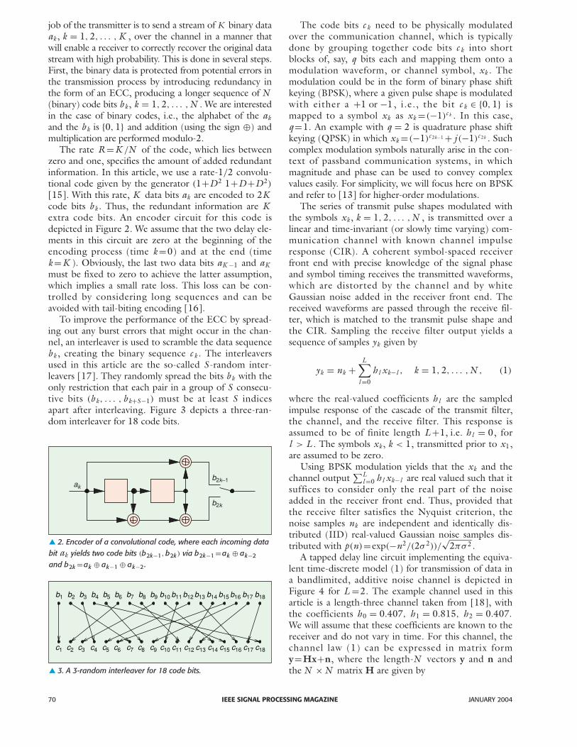
job of the transmitter is to send a stream of K binary dataak , k = 1, 2, . . . , K , over the channel in a manner thatwill enable a receiver to correctly recover the original datastream with high probability. This is done in several steps.First, the binary data is protected from potential errors inthe transmission process by introducing redundancy inthe form of an ECC, producing a longer sequence of N(binary) code bits b k , k = 1, 2, . . . ,N . We are interestedin the case of binary codes, i.e., the alphabet of the akand the b k is {0, 1} and addition (using the sign ⊕) andmultiplication are performed modulo-2.
The rate R=K /N of the code, which lies betweenzero and one, specifies the amount of added redundantinformation. In this article, we use a rate-1/2 convolu-tional code given by the generator (1+D2 1+D +D2)
[15]. With this rate, K data bits ak are encoded to 2Kcode bits b k . Thus, the redundant information are Kextra code bits. An encoder circuit for this code isdepicted in Figure 2. We assume that the two delay ele-ments in this circuit are zero at the beginning of theencoding process (time k =0) and at the end (timek =K ). Obviously, the last two data bits aK −1 and aKmust be fixed to zero to achieve the latter assumption,which implies a small rate loss. This loss can be con-trolled by considering long sequences and can beavoided with tail-biting encoding [16].
To improve the performance of the ECC by spread-ing out any burst errors that might occur in the chan-nel, an interleaver is used to scramble the data sequenceb k , creating the binary sequence c k . The interleaversused in this article are the so-called S -random inter-leavers [17]. They randomly spread the bits b k with theonly restriction that each pair in a group of S consecu-tive bits (b k, . . . , b k+S−1) must be at least S indicesapart after interleaving. Figure 3 depicts a three-ran-dom interleaver for 18 code bits.
The code bits c k need to be physically modulatedover the communication channel, which is typicallydone by grouping together code bits c k into shortblocks of, say, q bits each and mapping them onto amodulation waveform, or channel symbol, xk . Themodulation could be in the form of binary phase shiftkeying (BPSK), where a given pulse shape is modulatedwith either a +1 or −1, i.e., the bit c k ∈ {0, 1} ismapped to a symbol xk as xk =(−1)c k . In this case,q =1. An example with q = 2 is quadrature phase shiftkeying (QPSK) in which xk =(−1)c 2k−1 + j (−1)c 2k . Suchcomplex modulation symbols naturally arise in the con-text of passband communication systems, in whichmagnitude and phase can be used to convey complexvalues easily. For simplicity, we will focus here on BPSKand refer to [13] for higher-order modulations.
The series of transmit pulse shapes modulated withthe symbols xk , k = 1, 2, . . . ,N , is transmitted over alinear and time-invariant (or slowly time varying) com-munication channel with known channel impulseresponse (CIR). A coherent symbol-spaced receiverfront end with precise knowledge of the signal phaseand symbol timing receives the transmitted waveforms,which are distorted by the channel and by whiteGaussian noise added in the receiver front end. Thereceived waveforms are passed through the receive fil-ter, which is matched to the transmit pulse shape andthe CIR. Sampling the receive filter output yields asequence of samples yk given by
yk = nk +L∑
l =0
h l xk−l , k = 1, 2, . . . ,N , (1)
where the real-valued coefficients h l are the sampledimpulse response of the cascade of the transmit filter,the channel, and the receive filter. This response isassumed to be of finite length L +1, i.e. h l = 0, forl > L . The symbols xk , k < 1, transmitted prior to x1,are assumed to be zero.
Using BPSK modulation yields that the xk and thechannel output
∑Ll =0 h l xk−l are real valued such that it
suffices to consider only the real part of the noiseadded in the receiver front end. Thus, provided thatthe receive filter satisfies the Nyquist criterion, thenoise samples nk are independent and identically dis-tributed (IID) real-valued Gaussian noise samples dis-tributed with p(n)=exp(−n2/(2σ 2))/
√2πσ 2 .
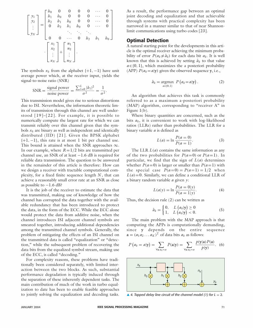
A tapped delay line circuit implementing the equiva-lent time-discrete model (1) for transmission of data ina bandlimited, additive noise channel is depicted inFigure 4 for L =2. The example channel used in thisarticle is a length-three channel taken from [18], withthe coefficients h0 = 0.407, h1 = 0.815, h2 = 0.407.
We will assume that these coefficients are known to thereceiver and do not vary in time. For this channel, thechannel law (1) can be expressed in matrix formy=Hx+n, where the length-N vectors y and n andthe N ×N matrix H are given by� 3. A 3-random interleaver for 18 code bits.
� 2. Encoder of a convolutional code, where each incoming databit ak yields two code bits (b2k−1, b2k) via b2k−1 =ak ⊕ ak−2
and b2k =ak ⊕ ak−1 ⊕ ak−2 .
ak
b2k–1
b2k
b1 b2 b3 b4 b5 b6 b7 b8 b9 b10 b11 b12 b13 b14 b15 b16 b17 b18
c18c17c16c15c14c13c12c11c10c9c8c7c6c5c4c3c2c1
IEEE SIGNAL PROCESSING MAGAZINEJANUARY 2004 71
y1y2...
yN
=
h0 0 0 0 0 · · · 0h1 h0 0 0 0 · · · 0h2 h1 h0 0 0 · · · 00 h2 h1 h0 0 · · · 0
. . .. . .
. . .
0 0 · · · 0 h2 h1 h0
·
x1x2...
xN
+
n1n2...
nN
.
The symbols xk from the alphabet {+1,−1} have unitaverage power which, at the receiver input, yields thesignal-to-noise ratio (SNR)
SNR = signal powernoise power
=∑L
l =0 |h l |2σ 2 = 1
σ 2 .
This transmission model gives rise to serious distortionsdue to ISI. Nevertheless, the information theoretic lim-its of transmission through this channel are well under-stood [19]–[22]. For example, it is possible tonumerically compute the largest rate for which we cantransmit reliably over this channel given that the sym-bols xk are binary as well as independent and identicallydistributed (IID) [21]. Given the BPSK alphabet{+1,−1}, this rate is at most 1 bit per channel use.This bound is attained when the SNR approaches ∞.In our example, where R=1/2 bits are transmitted perchannel use, an SNR of at least −1.6 dB is required forreliable data transmission. The question to be answeredin the remainder of this article is therefore: How canwe design a receiver with tractable computational com-plexity, for a fixed finite sequence length N , that canachieve a reasonably small error rate at an SNR as closeas possible to −1.6 dB?
It is the job of the receiver to estimate the data thatwas transmitted, making use of knowledge of how thechannel has corrupted the data together with the avail-able redundancy that has been introduced to protectthe data, in the form of the ECC. While the ECC alonewould protect the data from additive noise, when thechannel introduces ISI adjacent channel symbols aresmeared together, introducing additional dependenciesamong the transmitted channel symbols. Generally, theproblem of mitigating the effects of an ISI channel onthe transmitted data is called “equalization” or “detec-tion,” while the subsequent problem of recovering thedata bits from the equalized symbol stream, making useof the ECC, is called “decoding.”
For complexity reasons, these problems have tradi-tionally been considered separately, with limited inter-action between the two blocks. As such, substantialperformance degradation is typically induced throughthe separation of these inherently dependent tasks. Themain contribution of much of the work in turbo equal-ization to date has been to enable feasible approachesto jointly solving the equalization and decoding tasks.
As a result, the performance gap between an optimaljoint decoding and equalization and that achievablethrough systems with practical complexity has beennarrowed in a manner similar to that of near Shannon-limit communications using turbo codes [23].
Optimal DetectionA natural starting point for the developments in this arti-cle is the optimal receiver achieving the minimum proba-bility of error P (ak = ak) for each data bit ak . It is wellknown that this is achieved by setting ak to that valuea∈{0, 1}, which maximizes the a posteriori probability(APP) P (ak =a|y) given the observed sequence y, i.e.,
ak = argmaxa∈{0,1}
P(ak =a|y)
. (2)
An algorithm that achieves this task is commonlyreferred to as a maximum a-posteriori probability(MAP) algorithm, corresponding to “receiver A” inFigure 1(b).
Where binary quantities are concerned, such as thebits ak , it is convenient to work with log-likelihoodratios (LLRs) rather than probabilities. The LLR for abinary variable a is defined as
L (a) = lnP (a = 0)
P (a = 1). (3)
The LLR L (a) contains the same information as anyof the two probabilities for P (a=0) or P (a=1). Inparticular, we find that the sign of L (a) determineswhether P (a=0) is larger or smaller than P (a=1) withthe special case P (a=0) = P (a=1) = 1/2 whenL (a)=0. Similarly, we can define a conditional LLR ofa binary random variable a given y :
L (a|y ) = lnP (a = 0|y )
P (a = 1|y ). (4)
Thus, the decision rule (2) can be written as
ak ={
0, L(ak|y
) ≥ 01, L
(ak|y
)< 0.
(5)
The main problem with the MAP approach is thatcomputing the APPs is computationally demanding,since y depends on the entire sequencea = (a1a2 . . . aK )T of data bits ak as follows:
P(ak = a|y) =
∑
∀a:ak=a
P (a|y) =∑
∀a:ak=a
p(y|a)P (a)p(y)
. (6)
� 4. Tapped delay line circuit of the channel model (1) for L = 2.
xk
h0 h1 h2
nk
yk
IEEE SIGNAL PROCESSING MAGAZINE72 JANUARY 2004
The probability P (a) is the a-priori probability of thesequence a, which can be used in (6) to include knowl-edge about the source producing the bits ak . Usually,the bits ak are assumed independent, i.e., the jointprobability P (a) factors as
∏Kn=1 P (ak). Applying the
APP decomposition in (6) and that of P (a) to the con-ditional LLR L (ak|y) yields the following:
L(ak|y
) = ln
∑∀a:ak=0 p(y|a)∏K
i=1 P (ai )∑
∀a:ak=1 p(y|a)∏Ki=1 P (ai )
= ln
∑∀a:ak=0 p(y|a)∏K
i=1:i �=k P (ai )∑
∀a:ak=1 p(y|a)∏Ki=1:i �=k P (ai )︸ ︷︷ ︸
+L (ak)
= L ext(ak|y
) + L (ak). (7)
The quantity L ext(ak|y) is the extrinsic informationabout ak contained in y. It adds to the a priori informa-tion L (ak) about ak . Extrinsic LLRs will play a crucialrole in the turbo equalization setup.
Since the bits ak are usually assumed to be uniformlydistributed, i.e., they take on the values 0 or 1 equallylikely, we have that L (ak)=0.
As seen in (6), receiver A is impractical for largeblock lengths K because of the exponentially growingnumber 2K of terms p(y|a). In certain special cases,i.e., if the memory in the channel and in the inter-leaved coded sequence is only moderate, it is possibleto organize the computation in a significantly moreefficient fashion. Nevertheless, the number of opera-tions per information bit grows exponentially in thesum of channel and code memory, which in manycases renders the problem intractable. In this situation,turbo equalization offers suboptimal alternatives to theoptimal receiver, achieving comparable performancewhile requiring significantly reduced complexity. Wewill proceed by first developing the basic componentsof a turbo equalizer in a setting that separates theequalization and decoding tasks.
Separate Equalization and DecodingSince a MAP algorithm for optimal joint equalizationand decoding is usually not feasible, a standardapproach to reducing the computational burden of thereceiver is to split the detection problem into the twosubproblems: equalization and decoding. This strategyis illustrated in “receiver B” depicted in Figure 1. Oneimplementation communicates estimates xk , c k , and b kfrom the same alphabet ({0, 1} or {−1,+1}) as xk , c k ,and b k , respectively, from the equalizer to the decoder.An alternative is to communicate reliability or softinformation s (xk), s (c k), and s (b k), which providesmore information on the relative likelihood that xk , c k ,or b k take on any particular value.
We will consider two distinct families of algorithmsfor the subproblem of equalization, namely, trellis-
based methods and equalization methods based on lin-ear filtering. Typical trellis-based approaches includeMAP symbol detection [24], [25] and maximum-likeli-hood (ML) sequence detection [18], [26]. A MAPsymbol detector simply applies rule (2) while ignoringthe effect of the code; i.e., it sets the symbol estimatexk to that symbol x from {+1,−1}, which maximizesthe APP P (xk = x |y).
An ML sequence detector computes an estimate xof the entire sequence x, which maximizes the likeli-hood p(y|x). Both problems seem intractably com-plex because of the huge number of terms p(y|x) tobe summed up as in (6) or to be maximized over forML sequence detection. However, we will describehere a trellis-based approach in particular for MAPsymbol detection to show that these problems can besolved efficiently.
MAP Symbol DetectionConsider the tapped delay line model of the transmit-ter, channel, and receive filter depicted in Figure 4.Assuming an impulse response length of L +1, thetapped delay line contains L delay elements. Thus,given a binary input alphabet {+1,−1} the channel canbe in one of 2L states ri , i = 1, 2, . . . , 2L , correspon-ding to the 2L different possible contents of the delayelements. We denote by S = {r1, r2, . . . , r2L } the set ofpossible states. At each time instance k = 1, 2, . . . ,Nthe state of the channel is a random variable sk ∈ S. Itis an important property of the memory present in thesystem that, given sk , the state sk+1 can only assumeone of two values corresponding to a +1 or −1 beingfed into the tapped delay line at time k. The possibleevolution of states can thus be elegantly described inform of a trellis diagram. Any path through the trelliscorresponds to a sequence of input and output symbolsread from the branch labels, where the output symbolvk at time k is the noise-free output of the channelmodel (1):
vk =L∑
l =0
h l xk−l .
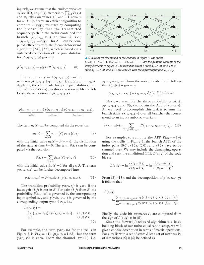
The trellis for the channel of Figure 4 is depictedin Figure 5. A branch of the trellis is a four-tuple(i, j, xi, j , vi, j ) such that state sk+1 =rj at time k + 1can be reached from state sk =ri at time k with inputxk = xi, j and output vk =vi, j , where xi, j and vi, j areuniquely identified by the index pair (i j ). The set ofall index pairs (i j ) corresponding to valid branchesis denoted B. For the trellis in Figure 5, the set B isas follows:
B={(00), (01), (12), (13), (20), (21), (33), (32)
}.
The trellis description turns out to be extremely use-ful in computing the APPs P (xk|y). Motivated by ourapproach of separating the equalization from the decod-
IEEE SIGNAL PROCESSING MAGAZINEJANUARY 2004 73
ing task, we assume that the random variablesxk are IID, i.e., P (x) factors into
∏Nk=1 P (xk)
and xk takes on values +1 and −1 equallyfor all k. To derive an efficient algorithm tocompute P (xk|y), we start by computingthe probability that the transmittedsequence path in the trellis contained thebranch (i, j, xi, j , vi, j ) at time k , i.e.,P (sk =ri , sk+1 =rj |y). This APP can be com-puted efficiently with the forward/backwardalgorithm [24], [27], which is based on asuitable decomposition of the joint distribu-tion p(sk, sk+1, y) given by
p(sk, sk+1, y
) = p(y) · P(sk, sk+1|y
). (8)
The sequence y in p(sk, sk+1, y) can bewritten as p(sk, sk+1, (y1, . . . , yk−1), yk, (yk+1, . . . , yN )).Applying the chain rule for joint probabilities, i.e.,P (a, b )=P (a)P (b |a), to this expression yields the fol-lowing decomposition of p(sk, sk+1, y):
p(sk, y1,. . . ,yk−1)︸ ︷︷ ︸αk(sk)
p(sk+1, yk|sk)︸ ︷︷ ︸γk(sk ,sk+1)
p(yk+1,. . . ,yN |sk+1)︸ ︷︷ ︸βk+1(sk+1)
.
The term αk(s ) can be computed via the recursion:
αk(s ) =∑
∀s ′∈Sαk−1
(s ′) γk−1
(s ′, s
)(9)
with the initial value α0(s )=P (s0 = s ), the distributionof the state at time k =0. The term βk(s ) can be com-puted via the recursion
βk(s ) =∑
∀s ′∈Sβk+1(s ′)γk(s , s ′) (10)
with the initial value βN (s )=1 for all s ∈ S. The termγk(sk, sk+1) can be further decomposed into
γk(sk, sk+1) = P (sk+1|sk) · p(yk|sk, sk+1). (11)
The transition probability γk(ri , rj ) is zero if theindex pair (i j ) is not in B. For pairs (i j ) from B, theprobability P (sk+1|sk) is governed by the correspondinginput symbol xi, j and p(yk|sk, sk+1) is governed by thecorresponding output symbol vi, j , i.e.,
γk(ri , rj
) ={
P(xk = xi, j
) · p(yk|vk = vi, j
), (i j ) ∈ B,
0, (i j ) /∈ B.
(12)
For example, the term γk(r0, r0) for the trellis in Figure 5 is P (xk =+1) · p(yk|vk =1.63), but the termγk(r0, r3) is zero. From the channel law (1), i.e.
yk =vk +nk , and from the noise distribution it followsthat p(yk|vk) is given by
p(yk|vk) = exp( − (yk − vk)
2/(2σ 2) )
/√
2πσ 2.
Next, we assemble the three probabilities α(sk),γk(sk, sk+1), and β(sk) to obtain the APP P (xk = x |y).All we need to accomplish this task is to sum thebranch APPs P (sk, sk+1|y) over all branches that corre-spond to an input symbol xk = x , i.e.,
P (xk = x |y)=∑
∀(i j )∈B:xi, j=x
P(sk =ri , sk+1 =rj |y
). (13)
For example, to compute the APP P (xk =+1|y)
using the trellis in Figure 5, the branch APPs of theindex pairs (0 0), (1 2), (2 0), and (3 2) have to besummed over. We may include the demapping opera-tion and seek the conditional LLR L (c k|y) of the codebit c k :
L (c k|y) = lnP (c k =0|y)
P (c k =1|y)= ln
P (xk =+1|y)
P (xk =−1|y).
From (8), (13), and the decomposition of p(sk, sk+1, y)
it follows that
L (c k|y)
= ln
∑∀(i j )∈B:xi, j=+1 αk (ri ) · γk
(ri , rj
) · βk+1(rj
)∑
∀(i j )∈B:xi, j=−1 αk (ri ) · γk(ri , rj
) · βk+1(rj
) .
Finally, the code bit estimates c k are computed fromthe sign of L (c k|y) as in (5).
Since the forward/backward algorithm is a basicbuilding block of our turbo equalization setup, we willgive a concise description in terms of matrix operations.For a trellis with a set of states S let a set of matrices Pkof dimensions |S| × |S| be defined as
� 5. A trellis representation of the channel in Figure 4. The statesr0 =(1, 1), r1 =(−1, 1), r2 =(1,−1), r3 =(−1,−1) are the possible contents of thedelay elements in Figure 4. The transitions from a state sk = ri at time k to astate sk+1 = rj at time k+1 are labeled with the input/output pair xi, j / vi, j .
r3
r2 r2 r2 r2
r1 r1 r1 r1
r0 r0 r0 r0
r3 r3 r3–1/–1.63
1/1.63 1/1.63 1/1.63
–1/–1.63 –1/–1.631/–0.815
–1/0.815
1/0.815
1/0.815
1/0.815
–1/0.815–1/0.815
1/–0.815
1/–0.815
1/–0.815
1/–0.8151/–0.815
1/01/01/0
–1/0 –1/0 –1/0
k–1 k+1 k+2k
IEEE SIGNAL PROCESSING MAGAZINE74 JANUARY 2004
{Pk}i, j = γk(ri , rj
), (14)
where {·}i, j denotes the entry of a matrix in the i throw and j th column. Moreover, let the matrices A(x )
be defined for x ∈ {+1,−1} as
{A(x )}i, j ={
1, (i j ) is a branch with xi, j = x ,
0, otherwise.(15)
For example, for the trellis in Figure 5 we find that
A(+1)=
1 0 0 00 0 1 01 0 0 00 0 1 0
, A(−1)=
0 1 0 00 0 0 10 1 0 00 0 0 1
.
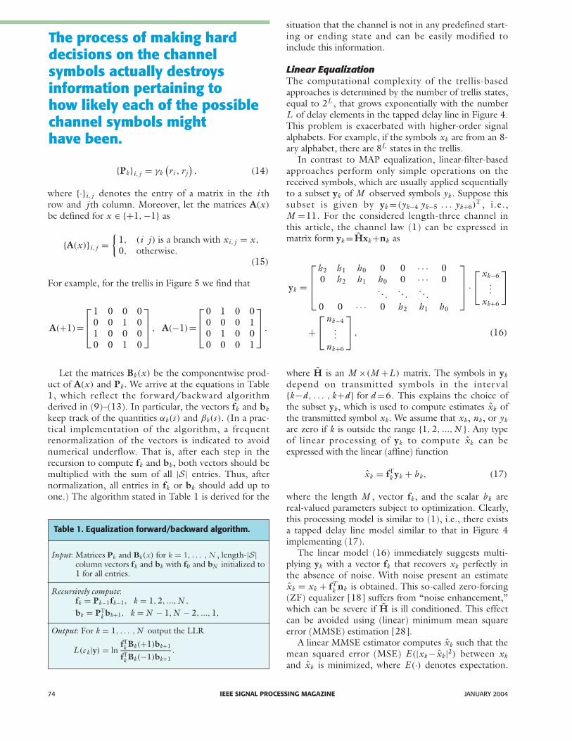
Let the matrices Bk(x ) be the componentwise prod-uct of A(x ) and Pk . We arrive at the equations in Table1, which reflect the forward/backward algorithmderived in (9)–(13). In particular, the vectors fk and bkkeep track of the quantities αk(s ) and βk(s ). (In a prac-tical implementation of the algorithm, a frequentrenormalization of the vectors is indicated to avoidnumerical underflow. That is, after each step in therecursion to compute fk and bk , both vectors should bemultiplied with the sum of all |S| entries. Thus, afternormalization, all entries in fk or bk should add up toone.) The algorithm stated in Table 1 is derived for the
situation that the channel is not in any predefined start-ing or ending state and can be easily modified toinclude this information.
Linear EqualizationThe computational complexity of the trellis-basedapproaches is determined by the number of trellis states,equal to 2L , that grows exponentially with the numberL of delay elements in the tapped delay line in Figure 4.This problem is exacerbated with higher-order signalalphabets. For example, if the symbols xk are from an 8-ary alphabet, there are 8L states in the trellis.
In contrast to MAP equalization, linear-filter-basedapproaches perform only simple operations on thereceived symbols, which are usually applied sequentiallyto a subset yk of M observed symbols yk . Suppose thissubset is given by yk =(yk−4 yk−5 . . . yk+6)
T , i.e.,M =11. For the considered length-three channel inthis article, the channel law (1) can be expressed inmatrix form yk =Hxk +nk as
yk =
h2 h1 h0 0 0 · · · 00 h2 h1 h0 0 · · · 0
. . .. . .
. . .
0 0 · · · 0 h2 h1 h0
·
xk−6
...
xk+6
+
nk−4
...
nk+6
, (16)
where H is an M ×(M +L ) matrix. The symbols in ykdepend on transmitted symbols in the interval{k−d, . . . , k+d} for d =6. This explains the choice ofthe subset yk , which is used to compute estimates xk ofthe transmitted symbol xk . We assume that xk , nk , or ykare zero if k is outside the range {1, 2, ...,N }. Any typeof linear processing of yk to compute xk can beexpressed with the linear (affine) function
xk = fTk yk + b k, (17)
where the length M , vector fk , and the scalar b k arereal-valued parameters subject to optimization. Clearly,this processing model is similar to (1), i.e., there existsa tapped delay line model similar to that in Figure 4implementing (17).
The linear model (16) immediately suggests multi-plying yk with a vector fk that recovers xk perfectly inthe absence of noise. With noise present an estimatexk = xk + fT
k nk is obtained. This so-called zero-forcing(ZF) equalizer [18] suffers from “noise enhancement,”which can be severe if H is ill conditioned. This effectcan be avoided using (linear) minimum mean squareerror (MMSE) estimation [28].
A linear MMSE estimator computes xk such that themean squared error (MSE) E (|xk − xk|2) between xkand xk is minimized, where E (·) denotes expectation.
The process of making harddecisions on the channelsymbols actually destroysinformation pertaining tohow likely each of the possiblechannel symbols mighthave been.
Input: Matrices Pk and Bk(x) for k = 1, . . . , N , length-|S|column vectors fk and bk with f0 and bN initialized to1 for all entries.
Recursively compute:fk = Pk−1fk−1, k = 1, 2, ...,N ,
bk = PTk bk+1, k = N − 1,N − 2, ..., 1,
Output: For k = 1, . . . ,N output the LLR
L (c k |y) = lnfT
k Bk(+1)bk+1
fTk Bk(−1)bk+1
.
Table 1. Equalization forward/backward algorithm.
IEEE SIGNAL PROCESSING MAGAZINEJANUARY 2004 75
This is achieved by the linear model
xk = E (xk) + fTk
(yk − E (yk)
)
fk = Cov(yk, yk)−1Cov(yk, xk), (18)
which is not purely linear because of the bias termsE (xk) and E (yk). The covariance Cov(a, b) of two col-umn vectors is defined as E (abT)−E (a)E (bT). Using(16) we can evaluate fk and E (yk) from
Cov(yk, yk) = σ 2I + HCov(xk, xk)HT,
Cov(yk, xk) = HCov(xk, xk),
E (yk) = HE (xk), (19)
where I is the M × M identity matrix. The independ-ence assumption on the symbols xk yields that thecovariance Cov(xk, xk′) between any two differentsymbols xk and xk′ vanishes. The covariance matrixCov(xk, xk) is therefore diagonal, and Cov(xk, xk) isequal to u · Cov(xk, xk), where u is a column vectorof zeros with the seventh position set to one corre-sponding to the seventh element xk of xk . Theremaining statistics E (xk) and Cov(xk, xk) areobtained from P (xk)
E (xk)=∑
∀x∈{+1,−1}x · P (xk = x ),
Cov(xk, xk)=∑
∀x∈{+1,−1} |x −E (xk)|2 · P (xk = x ).
(20)
The estimates xk are usually not in the symbolalphabet {+1,−1} and the decision whether +1 or −1have been transmitted is usually based on the estima-tion error ek = xk − xk . The distribution p(ek) of thiserror, given the estimator (18), has zero mean and vari-ance Cov(ek, ek)=Cov(xk, xk)−fT
k Hu [20]. Assumingfurthermore that p(ek) is Gaussian yields
p(ek) = exp( − e 2
k /(2 Cov(ek, ek))/√
2π Cov(ek, ek).
The hard decision of xk should be the symbolx ∈ {+1,−1} maximizing p(ek) , whichturns out to be the symbol x of closest dis-tance |x − xk| to xk .
Using the fairly standard IID assumptionon the symbols xk , we find thatE(xk)=0, Cov(xk, xk)=1 holds accordingto (20), and we arrive at the standard linearMMSE equalizer [18] according to (18):
x=fTk yk, fk =
(σ 2I+HHT
)−1Hu.
It is also possible to (nonlinearly) processprevious estimates to find the xk besides thelinear processing of yk . Such an approach isalso filter-based and called decision-feedbackequalization (DFE) [18].
Soft ProcessingThe equalizer can often provide more information tothe decoder than just the hard decisions (at the cost ofadditional storage, processing, and communication),such as probabilities that xk takes on a particular valuefrom {+1,−1}. The principle of using probabilities(soft information) rather than hard decisions is oftenreferred to as “soft decoding.” This is shown in thesecond implementation of receiver B in Figure 1(c), byindicating that soft information s (·) is flowing alongthe edges of the flowgraph.
A natural choice for the soft information s (xk) aboutthe transmitted symbols xk are the APPs P (xk|y) or,similarly, the LLRs L (c k|y) (including demapping),which are a “side product” of the MAP symbol detec-tor. Also, the (somewhat less complex) Viterbi equaliz-er may produce approximations of L (c k|y) using, e.g.,the soft-output Viterbi algorithm [29].
For filter-based equalizers, extracting soft informa-tion s (xk) is more involved [8], [12]. A commonapproach is to assume that the estimation error,ek = xk −xk , is Gaussian distributed with PDF p(ek).This approach can apply to other equalization algo-rithms producing estimates xk as well.
DecodingThe LLRs L (c k|y) can be converted back to probabili-ties as
P (c k = c |y)= exp(−c · L (c k|y)
)
1+exp(−L (c k|y)
) , (21)
where c ∈ {0, 1}. After deinterleaving P (c k|y) to P (b k|y),we are faced with the classical problem of decoding abinary convolutional code with probabilistic input. Let
p = (P (b1|y) P (b2|y) ... P (bN |y)
)T
be the set of probabilities input to the decoder. We seekan efficient MAP decoder computing estimates ak ofthe transmitted data bits ak from the LLRs L (ak|p), asin (5). Such a decoder may again use theforward/backward algorithm operating on a trellis
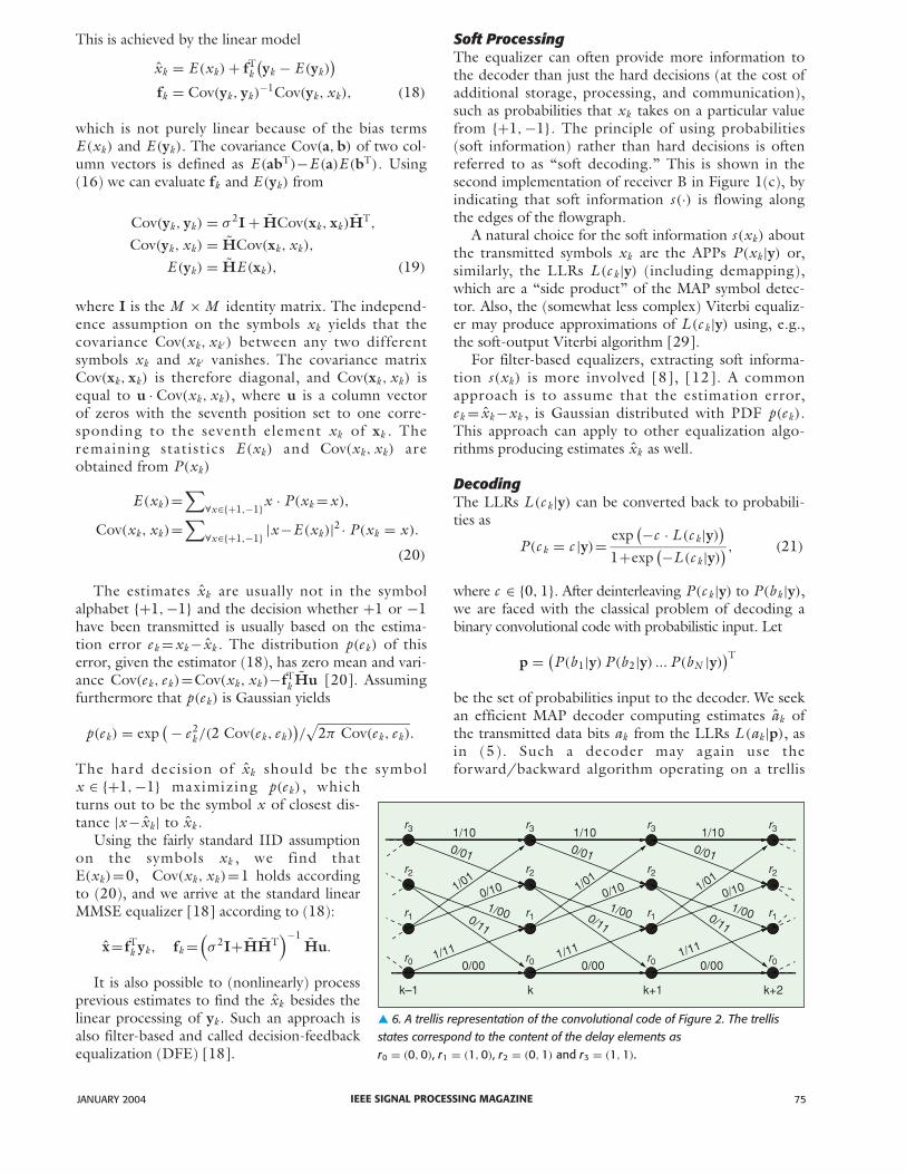
� 6. A trellis representation of the convolutional code of Figure 2. The trellisstates correspond to the content of the delay elements asr0 = (0, 0), r1 = (1, 0), r2 = (0, 1) and r3 = (1, 1).
r3 r3 r3r3
r2 r2 r2 r2
r1 r1 r1 r1
r0 r0 r0 r0
k–1 k k+1 k+2
1/10 1/10 1/100/01 0/01 0/01
1/011/01
1/010/10 0/10 0/10
1/00 1/00 1/000/11
1/11 1/11 1/11
0/110/11
0/00 0/00 0/00
IEEE SIGNAL PROCESSING MAGAZINE76 JANUARY 2004
description for the code, because its encoder in Figure2 is a tapped delay line similar to that of the channel inFigure 4. A trellis description of the encoder is given inFigure 6. The trellis branches are denoted by the tuple(i, j, ai, j , b1,i, j , b2,i, j ), where ai, j is the input bit akand (b1,i, j , b2,i, j ) are the two output bits (b2k−1, b2k)
belonging to the state transition (sk =ri , sk+1 =rj ). Theset B of valid transitions is the same as for the channeltrellis in Figure 5.
To apply the forward/backward algorithm as inTable 1, we have to adjust the way in which the matri-ces Pk and A(x ) are formed. We start by redefining thetransition probabilities γk(sk, sk+1) contained in Pk
γk(ri , rj ) ={
P (ak = ai, j )·0,
P(b2k−1 = b1,i, j |y
)P
(b2k = b2,i, j |y
), (i j ) ∈ B,
. . . (i j ) /∈ B.
(22)
For example, the term γk(r0, r0) for the trellis in Figure6 equals P (ak =0)P (b2k−1 =0|y)P (b2k =0|y) , whereP (ak =0)=1/2 under the IID assumption on the databits. The code bit probabilities follow from (21). Thematrices A(x ) are defined for x ∈ {0, 1} as
{A(x )
}i, j =
{1, (i j ) is a branch with ai, j = x ,
0, otherwise.
Besides the LLRs L (ak|p) required to compute theestimates ak , the decoder may compute as well theLLRs L (b k|p). These LLRs will serve as a priori infor-mation for the equalizer forward/backward algorithmlater. They can be computed using the forward/back-ward algorithm for decoding in Table 2 by simplychanging the definition of the matrices A(x ). The codebit LLRs L (b2k−1|p), k =1, 2, ..., K are computed bychoosing A(x ) as
{A(x )
}i, j =
{1, (i j ) is a branch with b1,i, j = x ,
0, otherwise.
The LLRs L (b2k|p), k =1, 2, ..., K are computed bychoosing A(x ) as
{A(x )
}i, j =
{1, (i j ) is a branch with b2,i, j = x ,
0, otherwise.
We arrive at the forward/backward algorithm fordecoding in Table 2. We note that this algorithm uses adifferent initialization of the vectors fk and bk , which isdue to the termination of the encoder to the zero stater0 at time steps k =0 and k =K .
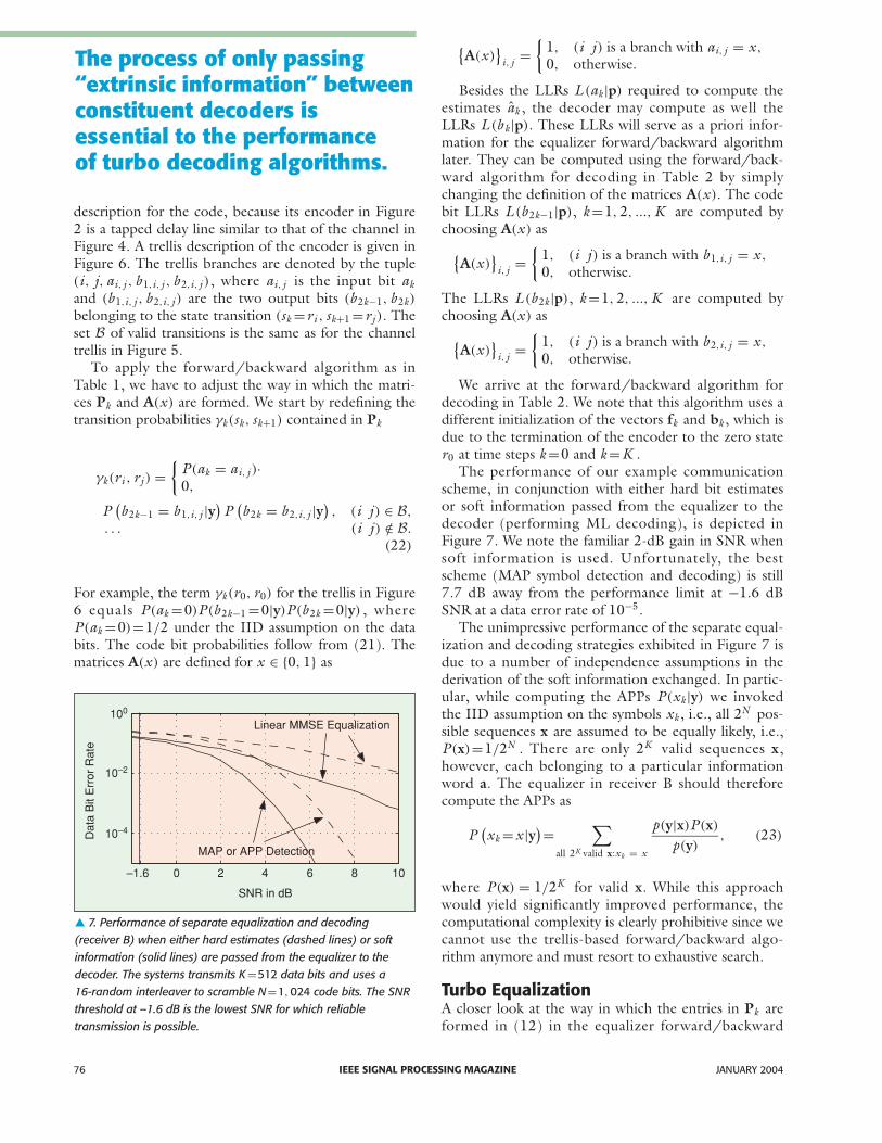
The performance of our example communicationscheme, in conjunction with either hard bit estimatesor soft information passed from the equalizer to thedecoder (performing ML decoding), is depicted in Figure 7. We note the familiar 2-dB gain in SNR whensoft information is used. Unfortunately, the bestscheme (MAP symbol detection and decoding) is still7.7 dB away from the performance limit at −1.6 dBSNR at a data error rate of 10−5.
The unimpressive performance of the separate equal-ization and decoding strategies exhibited in Figure 7 isdue to a number of independence assumptions in thederivation of the soft information exchanged. In partic-ular, while computing the APPs P (xk|y) we invokedthe IID assumption on the symbols xk , i.e., all 2N pos-sible sequences x are assumed to be equally likely, i.e.,P (x)=1/2N . There are only 2K valid sequences x,however, each belonging to a particular informationword a. The equalizer in receiver B should thereforecompute the APPs as
P(xk = x |y)=
∑
all 2K valid x:xk = x
p(y|x)P (x)
p(y), (23)
where P (x) = 1/2K for valid x. While this approachwould yield significantly improved performance, thecomputational complexity is clearly prohibitive since wecannot use the trellis-based forward/backward algo-rithm anymore and must resort to exhaustive search.
Turbo EqualizationA closer look at the way in which the entries in Pk areformed in (12) in the equalizer forward/backward
� 7. Performance of separate equalization and decoding (receiver B) when either hard estimates (dashed lines) or softinformation (solid lines) are passed from the equalizer to thedecoder. The systems transmits K=512 data bits and uses a 16-random interleaver to scramble N=1, 024 code bits. The SNRthreshold at –1.6 dB is the lowest SNR for which reliable transmission is possible.
Dat
a B
it E
rror
Rat
e
100
10–2
10–4
–1.6
SNR in dB
Linear MMSE Equalization
MAP or APP Detection
0 2 4 6 8 10
The process of only passing“extrinsic information” betweenconstituent decoders isessential to the performanceof turbo decoding algorithms.

IEEE SIGNAL PROCESSING MAGAZINEJANUARY 2004 77
algorithm reveals that they consist of two entries,namely, p(yk|vk =vi, j ) and P (xk = xi, j ) , wherep(yk|vk =vi, j ) can be interpreted as “local” evidenceabout which branch in the trellis was traversed, andP (xk = xi, j ) takes on the role of “prior” information,which accounts for any prior knowledge about theprobability of any branch in the trellis. In the separateequalization and decoding strategy given in the previ-ous section, the equalizer does not have any priorknowledge available, and the formation of entries in Pkrelies solely on the observed data yk . On the otherhand, the decoder forms the corresponding entries inPk without any local observations but entirely based onbitwise probabilities P (b k|y) provided by the equalizer.The bitwise probabilities are assembled into prior prob-abilities on the branches in (22). In any case, the for-ward/backward algorithm can be abstracted as a devicethat takes any observation y and any bitwise prior prob-ability and produces bit-wise APP values. A block dia-gram building block of the forward backwardalgorithm is given in Figure 8.
The performance of a forward/backward algorithmcan be greatly improved if good a priori information isavailable. Since we have two forward/backward algo-rithms, one for equalization and one for decoding, it isa natural idea to feed back the APP values of the indi-vidual bits obtained by one forward/backward algo-rithm as a priori information to the other. This is themain idea of turbo equalization. Some caution has tobe exercised when creating the feedbackloop, however. In particular, we have toavoid creating direct feedback that is toostrong. This consideration leads to thenotion of extrinsic and intrinsic information.
We showed already that the conditionalLLR L (ak|y) of the bit ak given the observa-tion y splits into the extrinsic LLR L ext(ak|y)
of ak contained in y plus the intrinsic LLRL (ak). It follows from (7) that L ext(ak|y)
does not depend on L (ak).In the case of the forward/backward
equalization algorithm that outputsL (c k|y), we can apply the same functionalrelation to separate the two contributionsto L (c k|y) into extrinsic informationL ext(c k|y)=L (c k|y)−L (c k) and intrinsicinformation L (c k). In turbo equalization, asin the turbo decoding principle in general,only extrinsic information is fed back, asdepicted in Figure 9. Feeding back intrinsicinformation L (c k) (included in L (c k|y))would create direct positive feedback, whichwould lead to fast convergence, though typi-cally far from the globally optimal solution.
The interleavers are included into the iter-ative update loop to further disperse thedirect feedback effect. In particular, the for-ward/backward algorithm creates output
that is locally highly correlated. The correlationsbetween neighboring symbols are largely suppressed bythe use of an interleaver.
The notation of L (b|p) = Forward/Backward(L ext(b|y)) will be used for the formation of an outputsequence of LLRs L (b k|p) using the forward/back-ward algorithm for decoding as shown in Table 2 usingthe LLRs L ext(c k|y) deinterleaved to L ext(b k|y) as a pri-ori LLRs. We will use the notation L (c|y) =Forward/Backward (L ext(c|p) for the formation of anoutput sequence of LLRs using the forward/backwardalgorithm for the equalizer utilizing the extrinsic LLRsL ext(b k|p) interleaved to L ext(c k|p) as a priori LLRs.We summarize the operations of a turbo equalizationscheme in Table 3.
While this formulation of the turbo equalization algo-rithm is based on two forward/backward algorithms,
� 8. The forward/backward algorithm as a schematic block taking prior probabilities and observations as input and producing a posteriori probabilities as output.
Observations y
Prior Probabilities L(a)
Forward/Backward
Algorithm
a PosterioriProbabilities L(b)
� 9. Block diagram of a turbo equalizer. At the center of the turbo equalizer aretwo forward/backward algorithms that can operate on observations and priorinformation about individual bits. Only the extrinsic information is fed back inthe iterative loop. The observation input of the forward backward algorithm forthe decoder is grounded to indicate that the decoding algorithm operates on apriori values alone.
Algorithm
Equalizer
Forward/Backward
Algorithm
Forward/Backward
Observations
y a PosterioriProbabilities
a PosterioriProbabilities
Prior Probabilities
Prior Probabilities
Interleaver
Lext(ckp)
Lext(bkp)
Lext(bky)
L(bkp)
Lext(cky)
L(cky)
Extrinsic Information
Extrinsic Information
+
+
Deinterleaver
Decoder
–
–

any pair of equalization and decoding algorithms thatmake use of soft information can be used as constituentalgorithms for the turbo equalizer by simply replacingthe operation L (c|y) = Forward/Backward (L ext(c|p))
by another operation, L (c|y) = Equalizer (L ext(c|p)),where this operation is any equalization algorithm thatcan map channel observations and soft inputs from thedecoder into soft outputs to feed back into the decoder.
For example, the linear MMSE equalizer can takeadvantage of the a priori LLRs L ext(c k|p) interpreted asprobabilities on the transmitted symbol xk by recom-puting E (xk) and Cov(xk, xk) according to (20), re-estimation of xk via (18), and recomputing of s (xk).Just as with the forward/backward equalization algo-rithm, to avoid short feedback cycles, such computa-tions are typically undertaken under the constraint thats (xk) is not a function of L ext(c k|p) at the same index k[12], [13]. This is equivalent to extracting only theextrinsic part of the information in the iterative scheme.We also note that several low-complexity alternativesfor re-estimating xk exist [12]–[14], [30]–[32].
The performance of our communication schemeusing receiver D from Figure 1 (turbo equalization) isdepicted in Figures 10 and Figure 11. We see a signifi-cant performance gain over the iterations using either
IEEE SIGNAL PROCESSING MAGAZINE78 JANUARY 2004
� 10. Performance of turbo equalization after 0, 1, 2, and 10 iterations using APP detection. The system parameters are asin Figure 7 (K=512, 16-random interleaver, SNR limit for reliabletransmission: –1.6 dB).
� 11. Performance of turbo equalization after 0, 1, 2, and 10 iterations using linear MMSE equalization. The system parameters are as in Figure 7 (K=512, 16-random interleaver,SNR limit for reliable transmission: –1.6 dB).
� 12. Two equivalent tapped delay line circuits of the channelmodel (1) for L=2 including the precoder xk=xk · xk−1. That is,the symbols xk are mapped before transmission to the symbolsxk=xk · xk−1. This mapping will not cause a complexityoverhead, since there exists a tapped delay circuit including theprecoder still requiring only two delay elements.
Input: Matrices Pk and Bk(x ) for k = 1, . . . , K , length-|S| column vectors fk and bk withf0 and bK initialized to 0 for all entriesexcept the first entry being 1.
Recursively compute:fk = Pk−1fk−1, k = 1, 2, ..., K ,bk = PT
k bk+1, k = K −1, k−2, ..., 1.
Output: For k = 1, 2, . . . , K output the LLR
L (ak |p) = lnfTk Bk(0)bk+1
fTk Bk(1)bk+1
.
The LLRs L (bk |p) are computed similarly.
Table 2. Decoding forward/backward algorithm.
Input: Channel coefficients h l for l = 0, 1, . . . , L .Observation sequence y.A sequence of LLRs L ext(c|p) initialized to 0. A predetermined number of iterations �.
Recursively compute for � iterations:L (c|y) = Forward/Backward
(Lext(c|p)
)
L ext(c|y) = L (c|y) − L ext(c|p)L (b|p) = Forward/Backward
(Lext(b|y)
)
L ext(b|p) = L (b|p) − L ext(b|y)
Output: Compute data bit estimates akfrom L (ak |y).
Table 3. Turbo equalization algorithm.
Dat
a B
it E
rror
Rat
e
100
10–2
10–4
–1.6
SNR in dB
0 2 4 6
10th
2nd 1st
0th
Dat
a B
it E
rror
Rat
e
100
10–2
10–4
–1.6
SNR in dB
0 2 4 6
10th
2nd 1st 0th
xk
xk
xk
nk
yk
h2h1h0
xk
h0 h2
nk
yk
h1
~
~

the APP detector or the linear MMSE equalizer. Wenote that for larger block lengths K , the linear MMSEequalizer performance approaches that of the APPdetector [12]. The performance is lower bounded bythat of the underlying rate-1/2 code used over an ISI-free channel at the same SNR, however. To improve(lower) this bound and to approach the performancelimit (we are still 6 dB away at 10−5 BER), we require adifferent error-correction code, such as the recursiveinner precoder xk = xk · xk−1 [33], [34] added to thechannel model as shown in Figure 12. Note theimprovement in the lower bound to within 1 dB of theperformance limit and the corresponding improvementin the turbo equalization algorithm in Figure 13.
Extensions and Concluding RemarksWe see that the turbo equalization approach to reliablecommunication over ISI channels is tightly connected torecent work in turbo codes, LDPC codes, and iterativedecoding algorithms. Just as turbo equalization grewout of the original turbo decoding algorithm, there arenumerous extensions of the basic turbo equalizationapproach in which a wide variety of signal processingtasks are incorporated into the joint estimation process[6]–[8], [10]–[14], [35]–[41]. There are a host of addi-tional ways in which to explore the turbo equalizationapproach based on explicit graphical models and iterativeestimation algorithms, and we refer the interested readerto the references mentioned here, the references con-tained therein and, of course, to the contributions con-tained in this special section. We hope that this briefoverview of the general concepts and salient featuresenables further exploration into this topic that we find tobe both challenging and fascinating.
Ralf Koetter received his diploma in electrical engineer-ing from the TU Darmstadt, Germany, in 1990 and his
Ph.D. degree from the Department of ElectricalEngineering, Linköping University, Sweden. From 1996to 1997, he was a visiting scientist at the IBM AlmadenResearch Lab. in San Jose, California. He was a visitingassistant professor at the University of Illinois atUrbana/Champaign and a visiting scientist at CNRS inSophia Antipolis, France from 1997 to 1998. He joinedthe faculty of the University of Illinois at Urbana/Champaign in 1999 and is currently an associate profes-sor at the Coordinated Science Laboratory and theDepartment of Electrical and Computer Engineering.His research interests include coding and informationtheory and their application to communication systems.He was associate editor for coding theory and techniquesfor IEEE Transactions on Communications and is an asso-ciate editor for coding theory of IEEE Transactions onInformation Theory. He received an IBM InventionAchievement Award in 1997, an NSF Career Award in2000, and an IBM Partnership Award in 2001.
Andrew C. Singer received the S.B., S.M., and Ph.D.degrees, all in electrical engineering and computer science,from the Massachusetts Institute of Technology in 1990,1992, and 1996, respectively. Since 1998, he has been onthe faculty of the Department of Electrical and ComputerEngineering at the University of Illinois at Urbana-Champaign, where he is currently an associate professorand a research associate professor in the CoordinatedScience Laboratory. During the academic year 1996, hewas a postdoctoral research affiliate in the ResearchLaboratory of Electronics at MIT. From 1996 to 1998, hewas a research scientist at Sanders, A Lockheed MartinCompany, in Manchester, New Hampshire. His researchinterests include statistical signal processing and communi-cation, universal prediction and data compression, andmachine learning. He was a Hughes Aircraft MastersFellow and the recipient of the Harold L. HazenMemorial Award for excellence in teaching in 1991. In2000, he received the National Science FoundationCAREER Award, in 2001 the Xerox Faculty ResearchAward, and in 2002 was named a Willett Faculty Scholar.He is an associate editor for IEEE Transactions on SignalProcessing and is a member of the MIT EducationalCouncil, Eta Kappa Nu, and Tau Beta Pi.
Michael Tüchler studied electrical engineering from 1995to 1997 at the Technical University Ilmenau, Germany,and from 1997 to 1998 at the Technical UniversityMunich, Germany. He received his M.S. degree fromthe University of Illinois at Urbana-Champaign in 2000.Currently he is pursuing a Ph.D. degree at the Institutefor Communications Engineering at the TechnicalUniversity Munich, Germany. In 2001, he was a visitingscientist at the IBM Research Lab Zurich, Switzerland.His research interests include coding theory, equaliza-tion, and estimation techniques with application to wire-line and wireless communication systems, magneticrecording, and sensor networks.
IEEE SIGNAL PROCESSING MAGAZINEJANUARY 2004 79
� 13. Performance of turbo equalization after 0, 1, 2, and 10iterations using MAP symbol detection and the precoder
xk = xk · xk−1.The system parameters are as in Figure 7 (K=512,16-random interleaver, SNR limit for reliable transmission: –1.6dB). The line displayed with “x” marks is the performance of thesame system with K = 25, 000 and S random interleaving(S = 40) after 20 iterations.
D
ata
Bit
Err
or R
ate
100
10–2
10–4
–1.6
SNR in dB
0 2 4 6
20th
10th 2nd
1st 0th
References[1] F. Kschischang, B. Frey, and H.A. Loeliger, “Factor graphs and the sum-prod-
uct algorithm,” IEEE Trans. Inform. Theory, vol. 47, pp. 498–519, Feb.2001.
[2] H.E. Gamal, “On the theory and application of space-time and graph-based codes,” Ph.D. dissertation, Dept. Elec. Comput.Eng., Univ. ofMaryland at College Park, 1999.
[3] N. Wiberg, “Codes and decoding on general graphs,” Ph.D. dissertation,Inst. Systems Theory, Linköping University, Linköping, Sweden, 1996.
[4] R. Gallager, “Low density parity check codes,” IRE Trans. Inform. Theory,vol. 8, pp. 21–28, Jan. 1962.
[5] H.-A. Loeliger, “An introduction to factor graphs,” IEEE Signal ProcessingMag., vol. 21, pp. 28–41, Jan. 2004.
[6] S. Benedetto, D. Divsalar, G. Montorsi, and F. Pollara, “Serial concatenat-ed trellis coded modulation with iterative decoding: Design and perform-ance,” in Proc. IEEE Global Telecomm. Conf., Nov. 1997.
[7] S. Benedetto and G. Mondorsi, “Unveiling turbo codes: Some results onparallel concatenated coding schemes,” IEEE Trans. Inform. Theory, vol.42, pp. 409–428, Mar. 1996.
[8] X. Wang and H. Poor, “Iterative (turbo) soft interference cancellation anddecoding for coded CDMA,” IEEE Trans. Commun., vol. 47, no. 7, pp.1046–1061, 1999.
[9] C. Douillard, M. Jezequel, C. Berrou, A. Picart, P. Didier, and A. Glavieux,“Iterative correction of intersymbol interference: Turbo equalization,”European Trans. Telecomm., vol. 6, pp. 507–511, Sept.–Oct 1995.
[10] G. Bauch and V. Franz, “A comparison of soft-in/soft-out algorithms for‘Turbo detection’,” in Proc. Int. Conf. Telecomm., June 1998, pp.259–263.
[11] A. Anastasopoulos and K. Chugg, “Iterative equalization/decoding forTCM for frequency-selective fading channels,” in Conf. Record 31thAsilomar Conf. Signals, Systems Comp., vol. 1, Monteray, CA, Nov. 1997,pp. 177–181.
[12] M. Tüchler, R. Koetter, and A. Singer, “Turbo equalization: Principlesand new results,” IEEE Trans. Comm., vol. 50, pp. 754–767, May 2002.
[13] M. Tüchler, A. Singer, and R. Kötter, “Minimum mean squared error(MMSE) equalization using priors,” IEEE Trans. Signal Processing, vol. 50,pp. 673–683, Mar. 2002.
[14] A. Glavieux, C. Laot, and J. Labat, “Turbo equalization over a frequencyselective channel,” in Proc. Intern. Symp. Turbo Codes, Brest, France, Sept.1997, pp. 96–102.
[15] S. Lin and J.J. Costello, Error Control Coding. Englewood Cliffs, NJ:Prentice-Hall, 1983.
[16] C. Weiss, C. Bettstetter, and S. Riedel, “Code construction and decodingof parallel concatenated tail-biting codes,” IEEE Trans. Inform. Theory,vol. 47, no. 1, pp. 366–386, Jan. 2001.
[17] C. Heegard and S. Wicker, Turbo Coding. Boston, MA: Kluwer, 1999.
[18] J. Proakis and M. Salehi, Communication Systems Engineering. UpperSaddle River, NJ: Prentice-Hall, 1994, pp. 577–595.
[19] T. Cover and J. Thomas, Elements of Information Theory. New York:Wiley, 1991.
[20] W. Hirt and J. Massey, “Capacity of the discrete-time Gaussian channelwith intersymbol interference,”IEEE Trans. Inform. Theory, vol. 34, pp.380–388, May 1988.
[21] D. Arnold and H.-A. Loeliger, “On the information rate of binary-inputchannels with memory,” in Proc. IEEE Intern. Conf. Comm., vol. 9, June2001, pp. 2692–2695.
[22] A. Kavcic´, “On the capacity of Markov sources over noisy channels,” inProc. Global Commun. Conf. (Globecom), Nov. 2003.
[23] C. Berrou and A. Glavieux, “Near optimum error correcting coding anddecoding: Turbo codes,” IEEE Trans. Comm., vol. 44, pp. 1261–1271,Oct. 1996.
[24] L. Bahl, J. Cocke, F. Jelinek, and J. Raviv, “Optimal decoding of linearcodes for minimizing symbol error rate,” IEEE Trans. Inform. Theory, vol.20, pp. 284–287, Mar. 1974.
[25] Y. Li, B. Vucetic, and Y. Sato, “Optimum soft-output detection for chan-nels with intersymbol interference,” IEEE Trans. Inform. Theory, vol. 41,pp. 704–713, May 1995.
[26] G. Forney, “Maximum-likelihood estimation of digital sequences in thepresence of intersymbol interference,” IEEE Trans. Inform. Theory, vol. 18,pp. 363–378, May 1972.
[27] L. Rabiner, “A tutorial on hidden Markov models and selected applica-tions in speech recognition,” Proc. IEEE, vol. 77, pp. 257–286, Feb. 1989.
[28] H. Poor, An Introduction to Signal Detection and Estimation, 2nd ed.New York: Springer-Verlag, 1994.
[29] J. Hagenauer and P. Hoeher, “A Viterbi algorithm with soft-decision out-puts and its applications,” in Proc. IEEE Global Telecomm. Conf., 1989, pp.1680–1686.
[30] M. Tüchler and J. Hagenauer, “Turbo equalization using frequencydomain equalizers,” in Proc. Allerton Conf., Monticello, IL, Oct. 2000, pp.1234–1243.
[31] D. Raphaeli and A. Saguy, “Linear equalizers for Turbo equalization: Anew optimization criterion for determining the equalizer taps,” in Proc.2nd Intern. Symp. Turbo Codes, Brest, France, Sept. 2000, pp. 371–374.
[32] Z. Wu and J. Cioffi, “Turbo decision aided equalization for magnetic record-ing channels,” in Proc. Global Telecomm. Conf., Dec 1999, pp. 733–738.
[33] K. Narayanan, “Effect of precoding on the convergence of turbo equaliza-tion for partial response channels,” IEEE J. Select. Areas Commun., vol. 19,pp. 686–698, Apr. 2001.
[34] I. Lee, “The effect of a precoder on serially concatenated coding systemswith an ISI channel,” IEEE Trans. Comm., vol. 49, pp. 1168–1175, July2001.
[35] P. Alexander, A. Grant, and M. Reed, “Iterative detection and code-divi-sion multiple-access with error control coding,” European Trans.Telecomm., vol. 9, pp. 419–425, Sept.–Oct. 1998.
[36] S. Ariyavisitakul and Y. Li, “Joint coding and decision feedback equaliza-tion for broadband wireless channels,” IEEE J. Select. Areas Commun., vol.16, pp. 1670–1678, Dec. 1998.
[37] A. Anastasopoulos and K. Chugg, “Adaptive soft-in soft-out algorithmsfor iterative detection with parameteric uncertainty,” IEEE Trans.Commun., vol. 48, pp. 1638–1649, Oct. 2000.
[38] A. Anastasopoulos and K. Chugg, “Adaptive iterative detection for phasetracking in turbo-coded systems,” IEEE Trans. Commun., vol. 49, pp.2135–2144, Dec. 2001.
[39] J. Nelson, A. Singer, and R. Koetter, “Linear iterative turbo-equalization(LITE) for dual channels,” in Proc. 33rd Asilomar Conf. Signals, Systems,Comp., Oct. 1999.
[40] J.R. Barry, A. Kavc ic´, S.W. McLaughlin, A. Nayak, and W. Zeng,“Iterative timing recovery,” IEEE Signal Processing Mag., vol. 21, pp.89–102, Jan. 2004.
[41] J.M.F. Moura, J. Lu, and H. Zhang, “Structured LDPC codes with largegirth,” IEEE Signal Processing Mag., vol. 21, pp. 42–55, Jan. 2004.
IEEE SIGNAL PROCESSING MAGAZINE80 JANUARY 2004