Embed Size (px)
Citation preview
STATUSOFTHEQUANTUMHALLRESISTANCERISP
RandolphE. ElmquistNational Institute of Standardsand Technologyt
Gaithersburg, MD20899, USA
Abstract
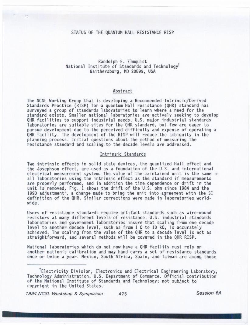
The NCSLWorking Group that is developing a RecommendedIntrinsic/DerivedStandards Practice (RISP) for a quantum Hall resistance (QHR) standard hassurveyed a group of standards laboratories to learn where a need for thestandard exists. Smaller national laboratories are actively seeking to developQHRfacilities to support industrial needs. U.S. major industrial standardslaboratories are suitable sites for the QHRstandard, but few are eager topursue development due to the perceived difficulty and expense of operating aQHRfacility. The development of the RISP will reduce the ambiguity in theplanning process. Initial questions about the method of measuring theresistance standard and scaling to the decade l~vels are addressed.
Intrinsic Standards
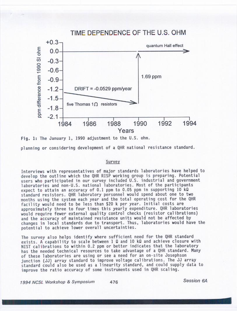
Two intrinsic effects in solid state devices, the quantized Hall effect andthe Josephson effect, are used as a foundation of the U.S. and internationalelectrical measurementsystem. The value of the maintained unit is the sameinall laboratories using the intrinsic effect as the standard if measurementsare properly performed, and in addition the time dependenceor drift in theunit is removed. Fig. 1 shows the drift of the U.S. ohmsince 1984 and the1990 adjustmentl, a change madeto bring the unit into agreement with the SIdefinition of the QHR.Similar corrections were made in laboratories world-wide.
Users of resistance standards require artifact standards such as wire-woundresistors at manydifferent levels of resistance. U.S. industrial standardslaboratories and government laboratories insure that scaling from one decadelevel to another decade level, such as from 1 C to 10 kC, is accuratelyachieved. The scaling from the value of the QHRto a decade level is not asstraightforward, and several methods will be covered in the QHRRISP.
National laboratories which do not now have a QHRfacility must rely onanother nation's calibration and may hand-carry a set of resistance standardsonce or twice a year. Mexico, South Africa, Spain, and Taiwan are amongthose
tElectricity Division, Electronics and Electrical Engineering Laboratory,Technology Administration, U.S. Department of Commerce.Official contributionof the National Institute of Standards and Technology; not subject tocopyright in the United States.
1994 NCSL Workshop & Symposium 475 Session 6A
1988 1990Years
Fig. 1: The January 1, 1990 adjustment to the u.s. ohm.
TIME DEPENDENCE OF THE U.S. OHM
E.r:.oeno0)0)~
+0.30.0
-0.3
-0.6
-0.9
-1.2-1.5 .
-1.8-2.1
I
1984 1986 1992 1994
quantum Halleffect:=-
1.69 ppmEo~....<I)oc:
'<I)~
~-cE0.0.
five Thomas 1{) ~
planning or considering development of a QHRnational resistance standard.
Survey
Interviews with representatives of major standards laboratories have helped todevelop the outline which the QHRRISP working group is preparing. Potentialusers who participated in our survey included u.S. industrial and governmentlaboratories and non-U.S. national laboratories. Most of the participantsexpect to attain an accuracy of 0.1 ppmto 0.05 ppmin supporting 10 kCstandard resistors. QHRlaboratory personnel would spend about one to twomonths using the system each year and the total operating cost for the QHRfacility would need to be less than $20 k per year. Initial costs areapproximately three to four times this yearly expenditure. QHRlaboratorieswould require fewer external quality control checks (resistor calibrations)and the accuracy of maintained resistance units would not be. affected bychanges in local standards due to transport. Thus, laboratories would have thepotential to achieve lower overall uncertainties.
The survey also helps identify where sufficient need for the QHRstandardexists. A capability to scale between 1 C and 10 kC and achieve closure withNISTcalibrations to within 0.2 ppmor better indicates that the laboratoryhas the needed technical resources to take advantage of a QHRstandard. Manyof these laboratories are using or see a need for an on-site Josephsonjunction (JJ) array standard to improve voltage calibrations. The JJ arraystandard could also be used as a linearity standard, and could supply data toimprove the ratio accuracy of some instruments used in QHRscaling.
1994 NCSL Workshop & Symposium 476 Session 6A
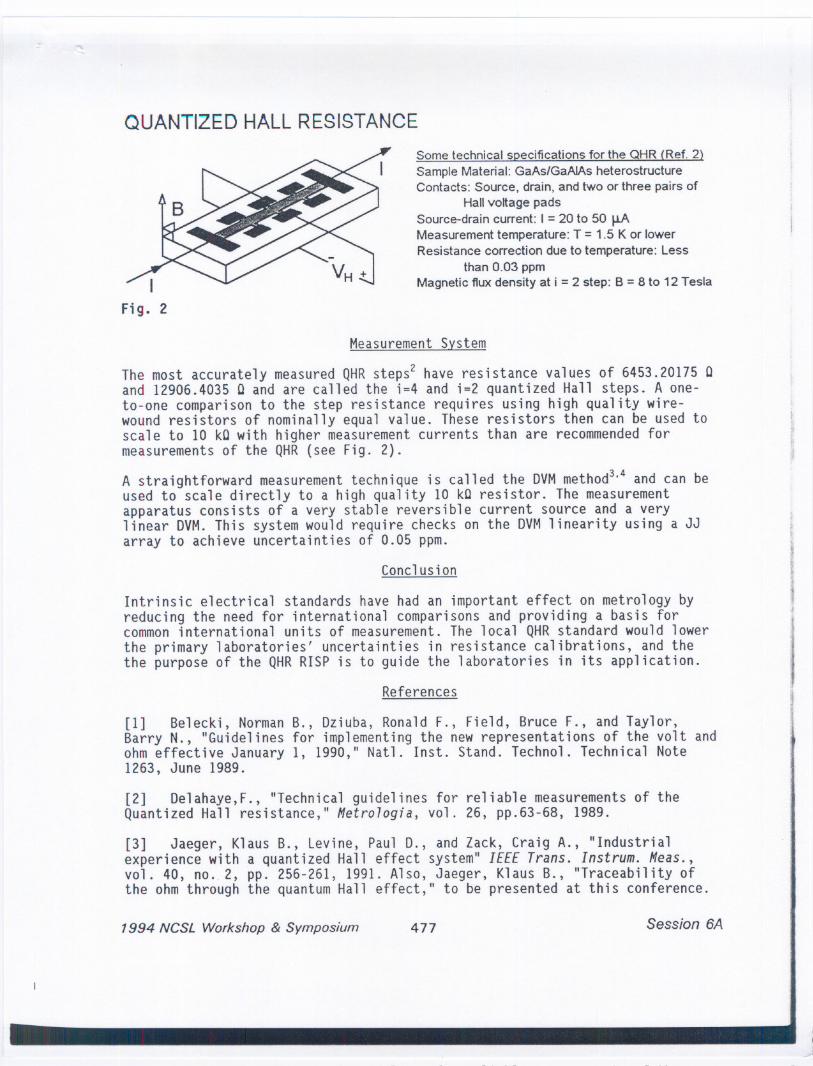
QUANTIZED HALL RESISTANCE
Sometechnical specifications for the QHR (Ref. 2)Sample Material: GaAs/GaAJAs heterostructureContacts: Source, drain, and two or three pairs of
Hallvoltage padsSource-drain current: I = 20 to 50 J.lAMeasurement temperature: T =1.5 Kor lowerResistance correction due to temperature: Less
than 0.03 ppmMagnetic fluxdensity at i =2 step: B =8 to 12 Tesla
Measurement System
The most accurately measured QHRsteps2 have resistance values of 6453.20175Cand 12906.4035 C and are called the i=4 and i=2 quantized Hall steps. A one-to-one comparison to the step resistance requires using high quality wire-wound resistors of nominally equal value. These resistors then can be used toscale to 10 kC with higher measurement currents than are recommendedformeasurements of the QHR(see Fig. 2).
A straightforward measurement technique is called the DVMmethod3.4 and can beused to scale directly to a high quality 10 kC resistor. The measurementapparatus consists of a very stable reversible current source and a verylinear DVM.This system would require checks on the DVMlinearity using a JJarray to achieve uncertainties of 0.05 ppm.
Conclusion
Intrinsic electrical standards have had an important effect on metrology byreducing the need for international comparisons and providing a basis forcommoninternational units of measurement.The local QHRstandard would lowerthe primary laboratories' uncertainties in resistance calibrations, and thethe purpose of the QHRRISP is to guide the laboratories in its application.
References
[1] Belecki, NormanB., Dziuba, Ronald F., Field, Bruce F., and Taylor,Barry N., "Guidelines for implementing the new representations of the volt andohm effective January 1, 1990," Natl. Inst. Stand. Technol. Technical Note1263, June 1989.
[2] Delahaye,F., "Technical guidelines for reliable measurements of theQuantized Hall resistance," Metro7ogia, vol. 26, pp.63-68, 1989.
[3] Jaeger, Klaus B., Levine, Paul D., and Zack, Craig A., "Industrialexperience with a quantized Hall effect system" IEEETrans. Instrum. Meas.,vol. 40, nO..2, pp. 256-261, 1991. Also, Jaeger, Klaus B., "Traceability ofthe ohm through the quantum Hall effect," to be presented at this conference.
1994 NCSL Workshop & Symposium 477 Session 6A
[4] Cage, Marvin E., Yu, Dingyi, Jeckelmann, Beat M., Steiner, Richard L.,and Duncan, Robert V., "Investigating the use of multimeters to measurequantized Hall resistance standards," IEEE Trans. Instrum. Meas., vol. 40, no.2, pp. 262-266, 1991.
1994 NCSL Workshop & Symposium478 Session 6A
1500
A1
500
-:.00
-10000.00 ~oo I~ 20.00 2S.DO 30.00 15.00
1-/510.00
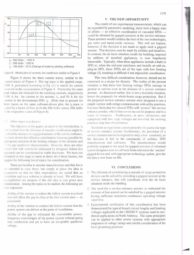
10-500 Ndiv; - 1400 AI, -500 Ndiv: 1350 A13- 100Ndiv : 50 A (Change of scale by plotting software)
Figure 8 - Model plot of currents, for conditions similar to Figure 4
Figure 8 shows the three current traces, similar to the
:l1rrent traces of Figure 4. The top trace is the applied surge,1400 A, postulated according to Eq. (I) to match the currentInvolved in the measurement of Figure 4. Practically the samepeak values are obtained for the resulting currents, respectively1300 A for the current in the arrester, 11,and 50 A for the~'urrent in the downstream SPD, 13' (Note that to present theIhree traces on the same software-driven plot, the 13trace is,caled by a factor of five, to fit the 500 A/div versus 100 A/divIf the respective scales of Figure 4).
! -I Other imfJortalltfactors
The objective of this paper, as stated in the introduction, is'Idy to show how the dilemma of cascade coordination might be.sulved by recourse to a gapped an-ester at the service entrance..\'~ have shown that effective coordination becomes possible bytppropriate selection of the limiting voltages of the varistors and>!the gap sparkover characteristics. However, there are otherl.lctors that will need to be addressed by designers before thislpproach can be transitioned to viable hardware. We have notIttempted at this stage to study in detail all of these factors, but~l1ggestthe following list of topics for consideration.
These are familiar to arrester manufacturers and this list is
lot intended to tutor them, but simply to place the idea inJ1~rspective so that no false expectations are raised that aniIl1l11ediateand easy solution is already at hand. We will haveJCcomplished our purpose if the old idea is just given new,,'onsideration. Among the topics to be studied, the following aremost important:
- Ability of the varistor to reduce the follow current to a levelUlat will allow the gap to clear at the first current zero - aspostulated.
Ability of the varistor to conduct the follow current that thepower system can deliver at the point of installation.
- Ability of the gap to withstand the unavoidable power-frequency overvoltages of the power system without goinginto conduction and yet to have an acceptable sparkovervoltage.
1179
V. THE NEW OPPORTUNITY
The resultsof our experimentalmeasurements,which canbe expanded by parametric modeling, show how a happy stateof affairs - an effective coordination of cascaded SPDs -could be obtained by gapped arresters at the service entrance.These an-esters would combine the best of the two technologies,gas tubes and metal-oxide varistors. This will not happen,however, if the decision is not made to apply such a gappedarrester. That decision must be made by utilities and installers.In contrast, the de facto situation inside the building, imposedby millions of installed appliances, is now hopelesslyimmovable. Typically, when these appliances include a built-inSPD or, when the end-user purchases and installs an add-on,plug-in SPD, these SPDs are of the type with low limitingvoltage [5], resulting in difficult if not impossible coordination.
This very difficult coordination, however, should not be
construed as a recipe for disaster. The reality of the presentsituation is that these low limiting voltage SPDs manage ingeneral to survive even in the absence of a service entrancearrester. As discussed earlier, this is not a desirable situation,hence the proposals for whole-house surge protection. But ifthe proposed service entrance arrester were designed to use asimple varistor with ratings commensurate with utility practices,it is most likely that the internal SPDs will "protect" the serviceentrance arrester, which then serves no useful purpose and is awaste of resources, Furthermore, as more electronics and
equipment with low logic voltages are installed, the existingpractices may lose elTectiveness.
Standards or regulations cannot prescribe the particular typeof service entrance arrester (furthermore, the provision of aservice entrance arrester is required in only a few countries), sothe decision is left to the community of utilities, SPDmanufacturers and end-users. The manufacturers would
probably respond to the need for gapped arresters if informedsystem designers were to call back from retirement the 'ancient'gapped device and, with appropriate technology update, give theold idea a new lease on life.
.,
I
i '
;~, I
! i I
VI. CONCLUSIONS
I. The dilemma of coordinating a cascade of surge-protectivedevices can be solved by providing a gapped arrester at theservice entrance, that will coordinate with the de factosituation inside the building.
2. The need for a service-entrance arrester to withstand the
scenario of lost neutral can be satisfied by a gapped arresterhaving sufficient maximum continuous operating voltagecapability.
3. Experimental verification of this coordination has beendemonstrated for typical branch circuit lengths and limitingvoltages applicable to the 120/240- V systems used in resi-dential applications in North America. The same principlescan be applied to other power systems with appropriateadaptation of voltage ratings and careful consideration of thelocal grounding practices.
1180
4. The behavior of a complex system such as the interactionsbetween circuit impedances and the nonlinear characteristics
of surge-protective devices can be successfully modeled toallow parametric studies.
5. Other factors need attention, for which good engineeringpractice applied by surge-protective device manufacturers canprovide adequate design.
6. While the idea appears sound, it cannot be implemented byindividual end-users. It will take an initiative by a centralizedorganization, such as the utility serving the district, topersuade manufacturers that a market opportunity exists towhich they can contribute.
VII. ACKNOWLEDGMENTS
Support for the development of this revisited approach wasprovided by the Power Quality Research groups of DelmarvaPower & Light and of Pacific Gas & Electric. Support for thetesting and modeling was provided by the Electric PowerResearch Institute.
VIII. REFERENCES
Matsuoka, Masyama & Ida, SupplementOl)' Journal (~fJa[lanese Socicty
(If Applied Physics, Vol 39, pp 94-10 I, 1970
! larnden, Martzloff, Morris, and Golden. "Metal-oxide Varistor: a Ncw
Way to Suppress Transients." Electronics, October 1972.
S;d.,shaug, Kresge, and Miske, "A New Concept in Station ArrcSklDesign," IEEE Transactions-PES-96. MarchI April 1977.
.t i\!artzloff, "Transient Overvoltage Protection: The Implications of NL~\\
Techniques," Proceedings. EMC Zurich 1981.
5 UL Standard 1449, Transient Voltage Surge Suppressors (1980).
() Martzloffand Leedy, "SelectingVaristorClampingVoltage:LowerIsNot Better!" Proceedings, EMC Zurich 1989.
7 Key, Mansoor, and Martzloff "No Joules for Surges: Relevant and
Realistic Assessment of Surge Stress Threats," Proceedings, 7th
International Conference on Harmonics and Quality (if Power, Las
Vegas, September 1996.
8. Key and Martzloff, "Surging the Upside-Down House: Looking intoUpsetting Reference Voltages," Proceedings, PQA '94, Amsterdam.October 1994.
l) IEC Publication 664, Insulation coordination within low-v(lfwgc
I')'stems, including clearances and creepage distance.rfor equiplI/cl/t,1980.
10 Standler, "Coordination of Surge Arresters For Use on Low-voltag~Mains," Proceedings, EMC Zurich 1991.
II Lai and Martzloff, "Coordinating Cascaded Surge-protective Devices:High-Low vs. Low-High," Conference Record, IEEE-IAS Meeting.October 1991. Also in IEEE Transactions, IAS 29-4 1993.
12 Hostfet and Huse, "Coordination of Surge Protective Devices in PowerSupply Systems: Needs for Protection," Proceedings, ICLP 1992
13. Hasse, Wiesinger, Zahlmann and Zischank, "Principle for an AdvancedCoordination of Surge Protective Devices in Low Voltage Systems,"Proceedings. /CLP /994.
14. Rousseau and Perche, "Coordination of Surge Arresters in the Low-Voltage Field," Proceedings. /7th International TelecommunicationsConference (INTELEC 95), 1995.
15. Traluient Voltage Suppre.r.rirJl1Device.r, Harris Corp., 1990.
16. IEEE C62.33-1982 (Reaffirmed 1989). IEEE Standard Test Spec~fi-cations for Varistor Surge-Protective Devices.
17. IEEE C62.41-199I,/EEE Recommended Practice on Surge Voltagesill Low- Voltage AC Power Circuits.
18. IEEE C62.45-1992, IEEE Guide on Surge Testing for EquipmentConnected to Low- Voltage AC Power Circuits.
19. Mansoor and Martzloff, "Driving High Surge Currents into LongCables: More Begets Less," IEEE Transactions PWRD /2, No.3. July1997.
20. Goedde, Dugan and Rowe, "Full Scale Lightning Surge Tests ofDistribution Transformers and Secondary Systems," IEEE - PESTransmission and. Distribution Conference Record, Dallas TX,September 1991.
21. Martzloff and Gauper, "Surge and High-Frequency Propagation inIndustrial Power Lines," IEEE Transactions IA-22, July 1986.
22. EPRI, "Electromagnetic Transients Program (EMTP), Version 2.0:Volume I; Main Program; Volume 2: Auxiliary Routines" EPRIReport EL-6421-L, July 1989.
23. Martzloff, Mansoor, Phipps and Grady, "Surging the Upside-DownHouse: Measurements and Modeling Results," Proceedings. PQA '95Conference, EPRI, 1995.
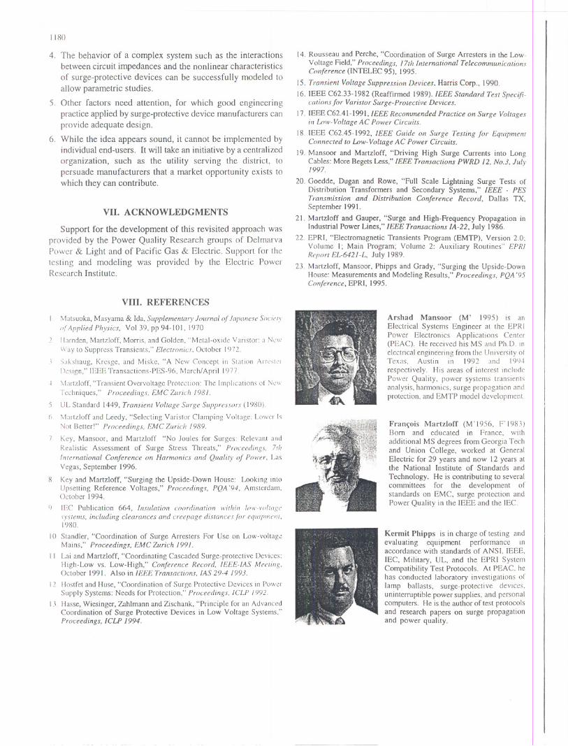
Arshad Mansoor (M' 1995) is anElectrical Systems Engineer at the EPR IPower Electronics Applications Center(PEAC). He received his MS and Ph.D. inelectrical engineering from the University 01Texas, Austin in 1992 and 19LJ4respectively. His areas of interest includePower Quality, power systems transientsanalysis, harmonics. surge propagation andprotection, and EMTP model development.
Fran~ois Martzloff (M'1956, F'1983)Born and educated in France, withadditional MS degrees from Georgia Techand Union College, worked at GeneralElectric for 29 years and now 12 years atthe National Institute of Standards and
Technology. He is contributing to severalcommittees for the development ofstandards on EMC, surge protection andPower Quality in the IEEE and the lEe.
Kermit Phipps is in charge of testing andevaluating equipment performance \11accordance with standards of ANSI. IEEE,IEC, Military, UL, and the EPRI SystemCompatibility Test Protocols. At PEAC, hehas conducted laboratory investigations oflamp ballasts, surgc-protecti ve devices.uninterruptible power supplies, and personalcomputers. He is the author of test protocolsand research papers on surge propagationand power quality.