Embed Size (px)
DESCRIPTION
Electrical diagrams and descriptions for Land Rover Range Rover Mk2 (P38) all models and variants from 1994 through to 2002.
Citation preview

Electrical Troubleshooting manual

Section Title
i Introduction
A1 Sequential Multiport Fuel Injection (SFI–V8)
A6 Diesel
B1 Starting and Charging
B5 Cruise Control
B6 Transfer Gearbox
B7 Automatic Gearbox
C1 Ignition and Shift Interlock
D1 Anti–Lock Brake System
D3 Data Link Connector
E1 Instruments
E2 Warnings and Indicators
E5 Horns
E6 Radio
E9 Navigation System
F5 Wash/Wipe
F6 Heated Front Screen
F9 Heated Rear Screen
G1 Electrochromatic Rear View Mirror
H1 Headlamps
H4 Side Lamps
H5 Stop Lamps
H6 Direction Indicator Lamps
H7 Reversing Lamps
H9 Fog Guard Lamps
J1 Interior Lamps
J2 Cigar Lighter/Clock/Accessory Socket
K3 Heating and Ventilation (without A/C)
K4 Heating and Ventilation (with A/C)
L1 Power Windows
L4 Sunroof
M1 Power Seats
M3 Power Mirrors
M4 Memory Seats
M6 Heated Seats
Electrical Troubleshooting Manual
1999 Models onward
M7 Memory Mirrors
N1 Supplementary Restraint System (SRS)
P1 Trailer Auxiliary Socket
S1 Air Suspension
S3 Security/Central Locking
Y1 Power Distribution
Y2 Fuse Details
Y5 Ground Distribution
Z4 Component Location Table
Z5 Component Location Views
Z6 Connector Views
Z8 Harness Routing
Z9 Index

KEY INFORMATIONi
!"
#$ % &'( ' )
*$ % &'( + %
,# % &'( ' )
% &'( ' )
-
*, !+
!
+ ' '
+ .) . . '
/+ +0 .
' /'+0
"% ) '
+ ) . % .
+ +- %
. )
(
.
!"
. ' % 1(
2 + " .
' ) '
2 +' 3 .
.' % '
2 .) % '
2 4 .' % '-
&+
+ )
+ /0 .
+ ' %
INTRODUCTION i
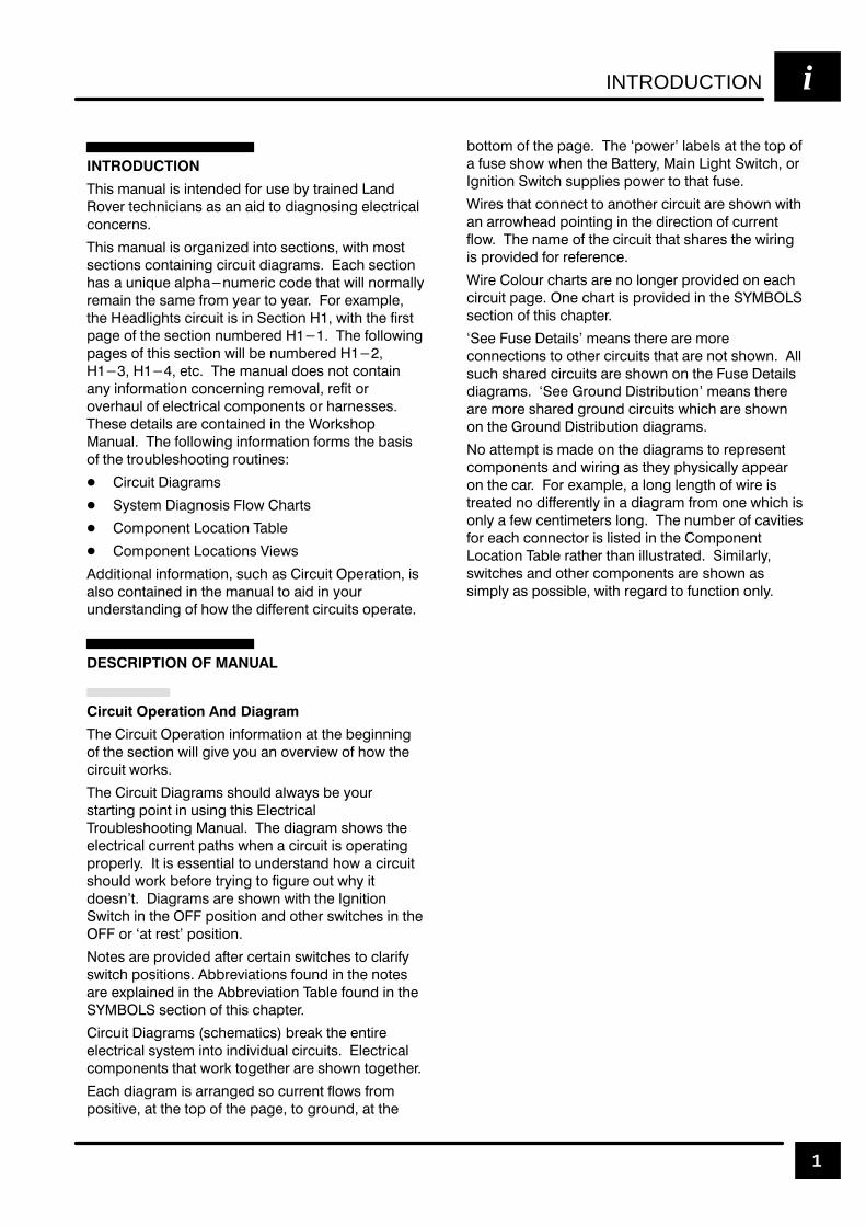
1
()2 ,!-4!+ )2 )-3%-$%$ &.1 42% "8 31!)-%$ !-$
.5%1 3%#(-)#)!-2 !2 !- !)$ 3. $)!'-.2)-' %+%#31)#!+
#.-#%1-2
()2 ,!-4!+ )2 .1'!-)9%$ )-3. 2%#3).-2 6)3( ,.23
2%#3).-2 #.-3!)-)-' #)1#4)3 $)!'1!,2 !#( 2%#3).-
(!2 ! 4-)04% !+/(!-4,%1)# #.$% 3(!3 6)++ -.1,!++8
1%,!)- 3(% 2!,% &1., 8%!1 3. 8%!1 .1 %7!,/+%
3(% %!$+)'(32 #)1#4)3 )2 )- %#3).- 6)3( 3(% &)123
/!'% .& 3(% 2%#3).- -4,"%1%$ (% &.++.6)-'
/!'%2 .& 3()2 2%#3).- 6)++ "% -4,"%1%$
%3# (% ,!-4!+ $.%2 -.3 #.-3!)-
!-8 )-&.1,!3).- #.-#%1-)-' 1%,.5!+ 1%&)3 .1
.5%1(!4+ .& %+%#31)#!+ #.,/.-%-32 .1 (!1-%22%2
(%2% $%3!)+2 !1% #.-3!)-%$ )- 3(% .1*2(./
!-4!+ (% &.++.6)-' )-&.1,!3).- &.1,2 3(% "!2)2
.& 3(% 31.4"+%2(..3)-' 1.43)-%2
)1#4)3 )!'1!,2
823%, )!'-.2)2 +.6 (!132
.,/.-%-3 .#!3).- !"+%
.,/.-%-3 .#!3).-2 )%62
$$)3).-!+ )-&.1,!3).- 24#( !2 )1#4)3 /%1!3).- )2
!+2. #.-3!)-%$ )- 3(% ,!-4!+ 3. !)$ )- 8.41
4-$%123!-$)-' .& (.6 3(% $)&&%1%-3 #)1#4)32 ./%1!3%
(% )1#4)3 /%1!3).- )-&.1,!3).- !3 3(% "%')--)-'
.& 3(% 2%#3).- 6)++ ')5% 8.4 !- .5%15)%6 .& (.6 3(%
#)1#4)3 6.1*2
(% )1#4)3 )!'1!,2 2(.4+$ !+6!82 "% 8.41
23!13)-' /.)-3 )- 42)-' 3()2 +%#31)#!+
1.4"+%2(..3)-' !-4!+ (% $)!'1!, 2(.62 3(%
%+%#31)#!+ #411%-3 /!3(2 6(%- ! #)1#4)3 )2 ./%1!3)-'
/1./%1+8 3 )2 %22%-3)!+ 3. 4-$%123!-$ (.6 ! #)1#4)3
2(.4+$ 6.1* "%&.1% 318)-' 3. &)'41% .43 6(8 )3
$.%2-3 )!'1!,2 !1% 2(.6- 6)3( 3(% '-)3).-
6)3#( )- 3(% /.2)3).- !-$ .3(%1 26)3#(%2 )- 3(%
.1 !3 1%23 /.2)3).-
.3%2 !1% /1.5)$%$ !&3%1 #%13!)- 26)3#(%2 3. #+!1)&8
26)3#( /.2)3).-2 ""1%5)!3).-2 &.4-$ )- 3(% -.3%2
!1% %7/+!)-%$ )- 3(% ""1%5)!3).- !"+% &.4-$ )- 3(%
2%#3).- .& 3()2 #(!/3%1
)1#4)3 )!'1!,2 2#(%,!3)#2 "1%!* 3(% %-3)1%
%+%#31)#!+ 2823%, )-3. )-$)5)$4!+ #)1#4)32 +%#31)#!+
#.,/.-%-32 3(!3 6.1* 3.'%3(%1 !1% 2(.6- 3.'%3(%1
!#( $)!'1!, )2 !11!-'%$ 2. #411%-3 &+.62 &1.,
/.2)3)5% !3 3(% 3./ .& 3(% /!'% 3. '1.4-$ !3 3(%
".33., .& 3(% /!'% (% /.6%1 +!"%+2 !3 3(% 3./ .&
! &42% 2(.6 6(%- 3(% !33%18 !)- )'(3 6)3#( .1
'-)3).- 6)3#( 24//+)%2 /.6%1 3. 3(!3 &42%
)1%2 3(!3 #.--%#3 3. !-.3(%1 #)1#4)3 !1% 2(.6- 6)3(
!- !11.6(%!$ /.)-3)-' )- 3(% $)1%#3).- .& #411%-3
&+.6 (% -!,% .& 3(% #)1#4)3 3(!3 2(!1%2 3(% 6)1)-'
)2 /1.5)$%$ &.1 1%&%1%-#%
)1% .+.41 #(!132 !1% -. +.-'%1 /1.5)$%$ .- %!#(
#)1#4)3 /!'% -% #(!13 )2 /1.5)$%$ )- 3(%
2%#3).- .& 3()2 #(!/3%1
%% 42% %3!)+2 ,%!-2 3(%1% !1% ,.1%
#.--%#3).-2 3. .3(%1 #)1#4)32 3(!3 !1% -.3 2(.6- ++
24#( 2(!1%$ #)1#4)32 !1% 2(.6- .- 3(% 42% %3!)+2
$)!'1!,2 %% 1.4-$ )231)"43).- ,%!-2 3(%1%
!1% ,.1% 2(!1%$ '1.4-$ #)1#4)32 6()#( !1% 2(.6-
.- 3(% 1.4-$ )231)"43).- $)!'1!,2
. !33%,/3 )2 ,!$% .- 3(% $)!'1!,2 3. 1%/1%2%-3
#.,/.-%-32 !-$ 6)1)-' !2 3(%8 /(82)#!++8 !//%!1
.- 3(% #!1 .1 %7!,/+% ! +.-' +%-'3( .& 6)1% )2
31%!3%$ -. $)&&%1%-3+8 )- ! $)!'1!, &1., .-% 6()#( )2
.-+8 ! &%6 #%-3),%3%12 +.-' (% -4,"%1 .& #!5)3)%2
&.1 %!#( #.--%#3.1 )2 +)23%$ )- 3(% .,/.-%-3
.#!3).- !"+% 1!3(%1 3(!- )++4231!3%$ ),)+!1+8
26)3#(%2 !-$ .3(%1 #.,/.-%-32 !1% 2(.6- !2
2),/+8 !2 /.22)"+% 6)3( 1%'!1$ 3. &4-#3).- .-+8

INTRODUCTIONi
2
%" ,3". &/0.&10&,+ !&$.*/ ." #,1+! &+
" 0&,+ %"/" !&$.*/ /%,3 %,3 2,)0$" &/
/1--)&"! #.,* 0%" -,/&0&2" 00".5 0".*&+) 0, 0%"
2.&,1/ &. 1&0/ &+ 0%" 2"%& )"
%" &+!&2&!1) &. 1&0 &$.*/ "$&+ 3&0% #1/" ,.
0%" $+&0&,+ 3&0 % ,3". &/0.&10&,+ /%,3/ 0%"
3&.&+$ #.,* 0%" 00".5 0, 0%" 1/" ,4"/ 0%"
$+&0&,+ 3&0 % 0%" &+ &$%0&+$ 3&0 % +! +5
&. 1&0 #1/"/ +,0 ), 0"! &+ 1/" ,4
%" 1/" "0&)/ !&$.*/ ." #,1+! &+ " 0&,+
%"/" !&$.*/ /%,3 )) 0%" 3&.&+$ "03""+ " %
#1/"/ &+ 0%" 1/" ,4"/ +! 0%" ,*-,+"+0/
,++" 0"! 0, 0%" ,10-10 ,# 0%" #1/" %" 1/"
"0&)/ !&$.*/ ." "40."*")5 %")-#1) &+ ), 0&+$
/%,.0 &. 1&0 0%0 1/"/ #1/" 0, ),3 %"/"
!&$.*/ )/, &! &+ 0.,1)"/%,,0&+$ + &+,-".0&2"
&. 1&0 5 /%,3&+$ /" ,+! &. 1&0 1/&+$ 0%" /*"
#1/" # 0%" /" ,+! &. 1&0 3,.(/ 0%"+ 0%" #1/" +!
".0&+ 3&."/ ,# 0%" &+,-".0&2" &. 1&0 ." $,,!
%" .,1+! &/0.&10&,+ !&$.*/ ." #,1+! &+
" 0&,+ %"/" !&$.*/ /%,3 3%& %
,*-,+"+0/ /%." " % $.,1+! -,&+0 %&/
&+#,.*0&,+ + ,#0"+ " 0&*"/2". 3%"+
0.,1)"/%,,0&+$ -,,. $.,1+!
,. "4*-)" &# 0%" 1") 1*- !,"/ +,0 .1+ 5,1
*5 /1/-" 0 + ,-"+ &+ &0/ &. 1&0 0, $.,1+!
,3"2". &# 0%" 1*". )0" *-/ 3,.( +! 0%"5
/%." 0%" /*" $.,1+! -,&+0 / 0%" 1") 1*- 5,1
(+,3 0%0 0%" $.,1+! +! 0%" 3&." 1- 0, 0%"
,**,+ /-)& " ." $,,! ,1 %2" )".+"! 0%&/
'1/0 5 &+/-" 0&+$ 0%" !&$.* +! (+,3&+$ 0%"
2"%& )"/ /5*-0,*/
,++" 0,. &"3/ ." -.,2&!"! &+ /" 0&,+ ))
,++" 0,./ 3&0% 0".*&+)/ ,. *,." 3&)) " /%,3+
&+6,10 0)"/ 3&0% 0%" --.,.&0" 3&." ,),1./ 3&))
)/, " /%,3+
,*-,+"+0 , 0&,+ )" + " #,1+! &+
" 0&,+ 4 "-0 #,. 0%" ), 0&,+ ,# ,2&,1/
,*-,+"+0/ )&(" 0%" "#0 "!)&$%0 0%" 0)" )&/0/
0%" ), 0&,+ ,# "2".5 ,*-,+"+0 ,++" 0,. +!
$.,1+! -,&+0 !"-& 0"! &+ 0%" &. 1&0 &$.*/ %"
0)" )/, $&2"/ ."#"."+ "/ 0, ,*-,+"+0 , 0&,+
&"3/ ), 0"! &+ " 0&,+ +! .,// ."#"."+ "/ 0,
,.(/%,- +1) ."*,2" +! ."#&0 -., "!1."
/" 0&,+/ %" +1*". ,# 2&0&"/ &+ " % ,++" 0,.
+! 0%" ,++" 0,. ,),1. &/ )/, )&/0"! &."/ *5
+,0 " 1/"! &+ )) ,++" 0,. 2&0&"/
INTRODUCTION i
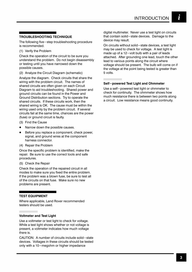
3
(% &.++.5)-' &)4%12%/ 20.3"+%1(..2)-' /0.#%$30%
)1 0%#.,,%-$%$
%0)&7 2(% 0."+%,
(%#* 2(% ./%0!2).- .& 2(% #)0#3)2 2. "% 130% 7.3
3-$%012!-$ 2(% /0."+%, . -.2 "%')- $)1!11%,"+7
.0 2%12)-' 3-2)+ 7.3 (!4% -!00.5%$ $.5- 2(%
/.11)"+% #!31%1
-!+78% 2(% )0#3)2 )!'0!, 1#(%,!2)#
-!+78% 2(% $)!'0!, (%#* #)0#3)21 2(!2 1(!0% 2(%
5)0)-' 5)2( 2(% /0."+%, #)0#3)2 (% -!,%1 .&
1(!0%$ #)0#3)21 !0% .&2%- ')4%- .- %!#( )0#3)2
)!'0!, 2. !)$ 20.3"+%1(..2)-' (!0%$ /.5%0 !-$
'0.3-$ #)0#3)21 #!- "% &.3-$ )- 2(% .5%0 !-$
0.3-$ )120)"32).- 1%#2).-1 07 2. ./%0!2% 2(%
1(!0%$ #)0#3)21 & 2(%1% #)0#3)21 5.0* 2(%- 2(%
1(!0%$ 5)0)-' )1 (% #!31% ,312 "% 5)2()- 2(%
5)0)-' 31%$ .-+7 "7 2(% /0."+%, #)0#3)2 & 1%4%0!+
#)0#3)21 &!)+ !2 2(% 1!,% 2),% #(!-#%1 !0% 2(% /.5%0
&31% .0 '0.3-$ #)0#3)2 )1 &!3+27
)-$ 2(% !31%
!00.5 $.5- 2(% /.11)"+% #!31%1
%&.0% 7.3 0%/+!#% ! #.,/.-%-2 #(%#* /.5%0
1)'-!+ !-$ '0.3-$ 5)0%1 !2 2(% #.,/.-%-2
(!0-%11 #.--%#2.0
%/!)0 2(% 0."+%,
-#% 2(% 1/%#)&)# /0."+%, )1 )$%-2)&)%$ ,!*% 2(%
0%/!)0 % 130% 2. 31% 2(% #.00%#2 2..+1 !-$ 1!&%
/0.#%$30%1
(%#* 2(% %/!)0
(%#* 2(% ./%0!2).- .& 2(% 0%/!)0%$ #)0#3)2 )- !++
,.$%1 2. ,!*% 130% 7.3 &)6%$ 2(% %-2)0% /0."+%,
& 2(% /0."+%, 5!1 ! "+.5- &31% "% 130% 2. 2%12 !++
.& 2(% #)0#3)21 .- 2(!2 &31% !*% 130% -. -%5
/0."+%,1 !0% /0%1%-2
(%0% !//+)#!"+% !-$ .4%0 0%#.,,%-$%$
2%12%01 1(.3+$ "% 31%$
"" !" "
1% ! 4.+2,%2%0 .0 2%12 +)'(2 2. #(%#* &.0 4.+2!'%
()+% ! 2%12 +)'(2 1(.51 5(%2(%0 .0 -.2 4.+2!'% )1
/0%1%-2 ! 4.+2,%2%0 )-$)#!2%1 (.5 ,3#( 4.+2!'%
2(%0% )1
-3,"%0 .& #)0#3)21 )-#+3$% 1.+)$12!2%
$%4)#%1 .+2!'%1 )- 2(%1% #)0#3)21 1(.3+$ "% 2%12%$
.-+7 5)2( ! ,%'.(, .0 ()'(%0 ),/%$!-#%
$)')2!+ ,3+2),%2%0 %4%0 31% ! 2%12 +)'(2 .- #)0#3)21
2(!2 #.-2!)- 1.+)$12!2% $%4)#%1 !,!'% 2. 2(%
$%4)#% ,!7 0%13+2
- #)0#3)21 5)2(.32 1.+)$12!2% $%4)#%1 ! 2%12 +)'(2
,!7 "% 31%$ 2. #(%#* &.0 4.+2!'% 2%12 +)'(2 )1
,!$% 3/ .& ! 4.+2 "3+" 5)2( ! /!)0 .& +%!$1
!22!#(%$ &2%0 '0.3-$)-' .-% +%!$ 2.3#( 2(% .2(%0
+%!$ 2. 4!0).31 /.)-21 !+.-' 2(% #)0#3)2 5(%0%
4.+2!'% 1(.3+$ "% /0%1%-2 (% "3+" 5)++ #.,% .- )&
2(% 4.+2!'% !2 2(% /.)-2 "%)-' 2%12%$ )1 '0%!2%0 2(!-
4.+21
# !" " "
1% ! 1%+&/.5%0%$ 2%12 +)'(2 .0 .(,,%2%0 2.
#(%#* &.0 #.-2)-3)27 (% .(,,%2%0 1(.51 (.5
,3#( 0%1)12!-#% 2(%0% )1 "%25%%- 25. /.)-21 !+.-'
! #)0#3)2 .5 0%1)12!-#% ,%!-1 '..$ #.-2)-3)27

INTRODUCTIONi
4
($ '% %#")$ &%& & "!
$'&% && "!&! %"%&& (%
&" &% (% * $%'&
"% ! %"%&& (% ! $'& !
! " &$ ( % $! " ! "'&
" #"!!& % &! %'$ !& &
"! $! $($% & % ! & %"!
$! & $!% $ & " #"!!& %
&! & %'$ !&
$'&% && "!&! %"%&& (% %"'
"!* &%& )& " "$ $
#! & '& &$
%#")$ &%& & "!%%&% " & '
&&$* ! &)" % & % $ &"'
&"&$ & ' ) " "!
%#")$ &%& & % "!* '% "! !
'!#")$ $'& $%& %"!!& & &&$* "$
$ "( & '% && % & $'& *"' $
)"$! "! & &)" #"!&% "! & $'&
&$"' ) &$ %"' "!&!'&* "!!&
"! " & %#")$ &%& & &"
#"!& &$ % "!&!'&* & &%& &% $'& )
" #& ! & ' ) " "!
% '% ' #$ )$ &" *#%% ! "#! $'&
'% ' #$ )$ % '# " ! !! '%
"$ "!!& &" %& " &%& % ($ '%
' #$ )$ $"%% !* " % $& &&$*
%"$& ) ") & '%
"")! %* " $#$%!&% '% ' #$

&&$+
!,#" "!" %)&
)",#" %)&
% ! !&%
! "!!&"!
&)! %)&%
$ $%%&"$ #$
"(% + *&$! "$
'&# "%&"! )&
M
"&!&" &$ #$ "(%
+ *&$! "$
" '$$!& ")% !
$&"! " $$") "!+
'
&$"! "$ " && (
$ !!& !&
"&"$ "! %#
&$! "' ! "&$+
"'#$
$ !!& !& "&"$
&)" %#
'%
*,'%
INTRODUCTION i
5
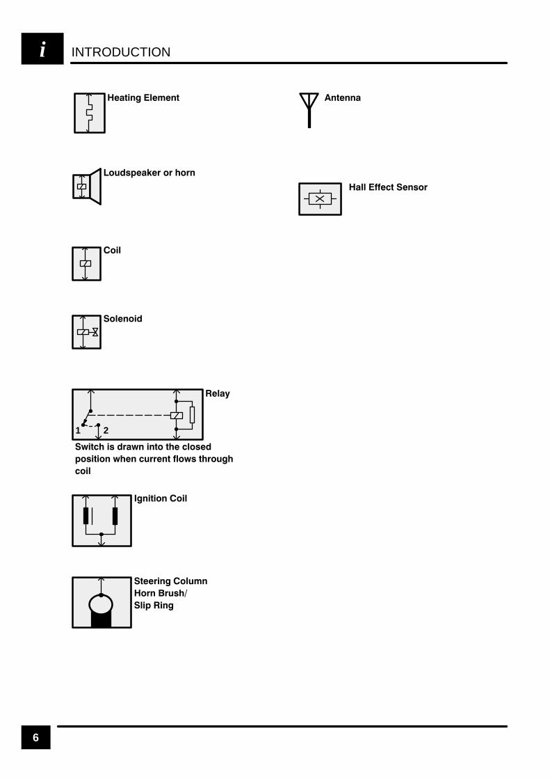
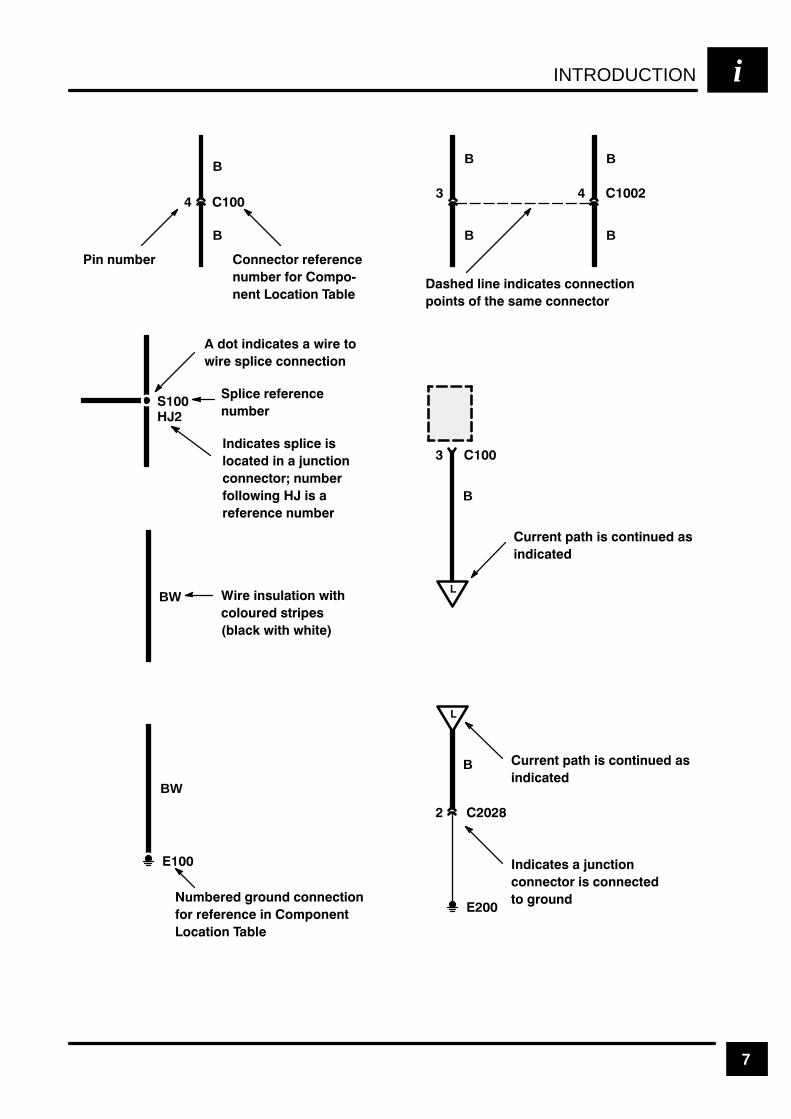
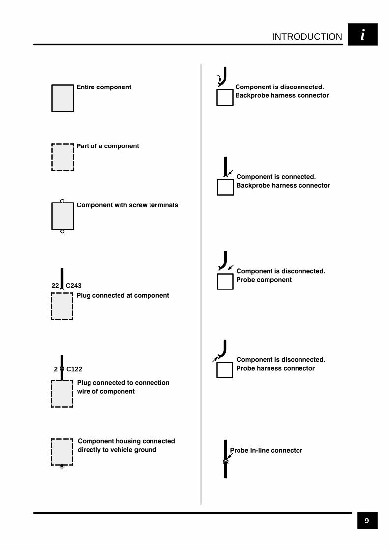
SYMBOLS
The abbreviations and symbols explained here areused troughout the manual; it is necessary to knowwhat they mean in order to use the diagramseffectively.
INTRODUCTIONi
6
1 2
INTRODUCTION i
7
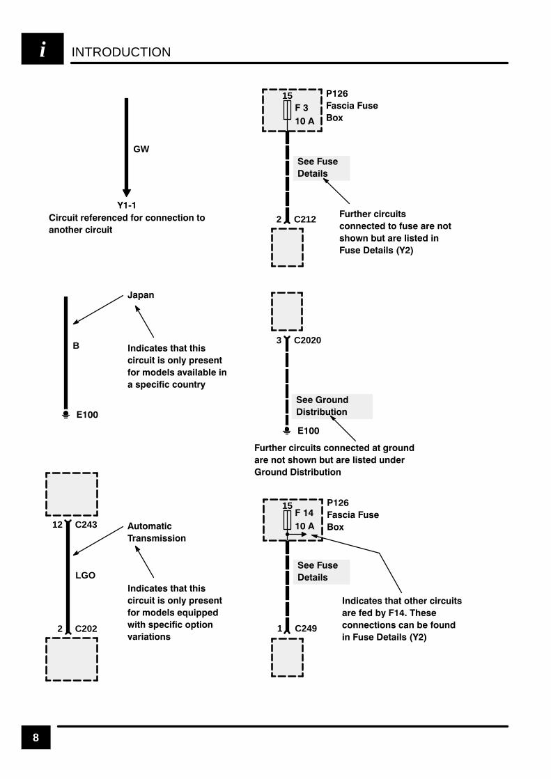
% %+$( &%%*&( ((%
%+$( &( &$'&-
%%* &* &% #
&* % *) , ( *&
, ( )'# &%%* &%
( %)+#* &% , *
&#&+( )*( ')
#" , * , *
+$( (&+% &%%* &%
&( ((% % &$'&%%*
&* &% #
) # % % *) &%%* &%
'& %*) & * )$ &%%*&(
+((%* '* ) &%* %+ )
% *
'# ((%
%+$(
% *) )'# )
#&* % !+%* &%
&%%*&( %+$(
&##&, % )
((% %+$(
+((%* '* ) &%* %+ )
% *
% *) !+%* &%
&%%*&( ) &%%*
*& (&+%
B
B B
B B
B
BW
BW
B
B
INTRODUCTIONi
8
/
'* ) ''# $' $##) $# )$
#$)' '* )
*(
) !(
*')' '* )(
$##) )$ *( ' #$)
($,# *) ' ! () #
*( ) !(
'$*#
()' *) $#
*')' '* )( $##) ) '$*#
' #$) ($,# *) ' ! () *#'
'$*# ()' *) $#
*(
) !(
( *(
$-
# )( )) $)' '* )(
' . (
$##) $#( # $*#
# *( ) !(
15
( *(
$-
15
2 C212
3 C2020
1 C249
12 C243
2 C202
LGO
GW
*)$")
'#(" (( $#
# )( )) ) (
'* ) ( $#!. %'(#)
$' "$!( &* %%
, ) (% $%) $#
+' ) $#(
B
%#
# )( )) ) (
'* ) ( $#!. %'(#)
$' "$!( + !! #
(% $*#)'.
INTRODUCTION i
9
22 C243
2 C122

INTRODUCTIONi
10
&+(0(,+
3(0"'
,%%
. #(,
(&+(0(,+
/0 .0
$.*(+ ) +1*!$. ,*-,+$+0 #$/(&+ 0(,+
5 .$"$(2$/ ! 00$.4 2,)0 &$
(+ -,/(0(,+/
$.*(+ )
+1*!$.
$/(&+ 0(,+
00$.4 2,)0 &$ &+(0(,+
3(0"' (+ -,/(0(,+
00$.4 2,)0 &$ /1--)($#
",+/0 +0)4
00$.4 2,)0 &$ &+(0(,+
3(0"' (+ -,/(0(,+ ,.
00$.4 2,)0 &$ &+(0(,+
3(0"' (+ -,/(0(,+/
$.*(+ )
+1*!$.
$/(&+ 0(,+
3(0"'$# ! 00$.4 2,)0 &$
0'.,1&' 0'$ (&+(0(,+ ), #
.$) 4 ,. ""$//,.4 .$) 4
(&+(0(,+ /3(0"' (/ (+ -,/(0(,+
,.
) /'$. 1+(0 (+-10
) /'$. 1+(0 ,10-10
(&' !$ *
! ,3 !$ *
+# ,% .$) 4 ",()
0 .0 ,% .$) 4 ",()
$) 4 ",+0 "0
$) 4 ",+0 "0
.,1+#
0 .0
# $ #) *- %) /'
(#$ ) *-/
INTRODUCTION i
11
. %
.) % % + '
'
% .
+- 3 -
- '
'- 3
4 5
. . 6
7 %- -
-
8+ 1 8+
9 )
: -
+- - -
! !
7
'
)
" "'
+
!%
+
4 4
; ;)
) . % )
+ 4 + < ) %
) . ' +'
+ + .)' 1
) + &
4 +
! !
7
'
)
" "'
+
!%
+
4 4
; ;)
4 +
' ) .)
' . ) &
) + .
) . ' .
' ) .)
% ' ) & )
) ' . '
' . - )
=+ . )
&+ 1 )
' >+.
' ) .
- +% & ) &
?>+.@ . &+ )
+ . 8 1-
' ' . '
' . '
?@ ) ) + .
. . '- ?@
) ) + . .
. '

INTRODUCTIONi
12 REV: 11/2000
!" " #
$
!% ! %
&% & %
' '
(
(
(
) *++ ! *++
, *++ *++(- ( -
.
/0123 /
04 5/01236
7 8 7 0 9
7 8 7
# #
# 7 # 7
#
-//0:9
!
&
(
/ ; 2
/ ; 2
! 2 #
& 2 #
( #
#
< <
SEQUENTIAL MULTIPORT FUEL INJECTION (SFI–V8) A1
CIRCUIT OPERATION 1REV: 09/2001
CIRCUIT OPERATION
Sensors
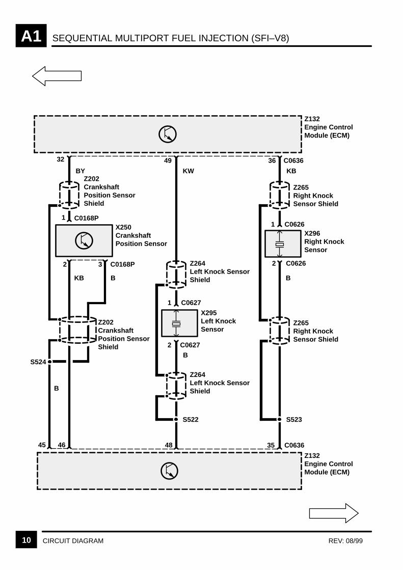
Knock Sensors (X309, X310)
The Knock Sensor is a “Piezo–electricaccelerometer,” i.e. it produces an output voltageproportional to mechanical vibration produced by theengine. The Engine Control Module (ECM) (Z132)receives the signal, filters out any noise andcalculates if the engine is knocking. Due to the camand crank signals supplying information regardingthe position of the engine in it’s cycle, the ECM(Z132) can work out exactly which cylinder isknocking and retards the ignition on that particularcylinder until the knock disappears. It then advancesthe ignition again to find the optimum ignition pointfor that cylinder for those conditions (i.e. fuel type,air temperature etc.). The ECM (Z132) will be able toadjust cylinder timing for knock simultaneously, sothat all eight cylinders could have different advanceangles at the same time.
Engine Coolant Temperature Sensor (X126)
The sensor contains two thermistors with negativetemperature co–efficients, i.e. the resistance of themetal strips varies with temperature. The EngineCoolant Sensor (X126) signal is vital to correctengine operation, as the injected fuel quantity isdependant upon the engine temperature, i.e. richermixture at low temperatures.
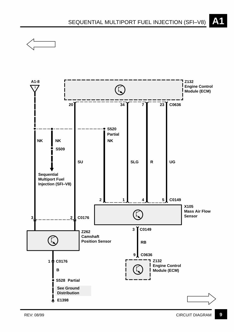
Crankshaft Position Sensor (X250)
The Engine Control Module (ECM) (Z132) uses thesignal produced by the Crankshaft Position (CKP)Sensor to determine the exact position of thecrankshaft to enable accurate ignition and fuelinjection timing. The ECM also determines enginespeed at any particular instance through the analysisof the frequency of fluctuations induced in the CKPsensor as the teeth of the reluctor ring pass by thesensor tip.
Camshaft Position Sensor (Z262)
The CMP sensor is a Hall effect sensor whichproduces four pulses for every two enginerevolutions. The signal is used in two areas: injectortiming corrections for fully sequential fuelling andactive knock control.
Camshaft operation is essential to continue normalignition, i.e. actuate the Fuel Injectors in the normalsequential order, timing the injection correctly withrespect to top dead centre.
In this way the sequential fuelling will either becorrect, or one engine revolution out ofsynchronisation.
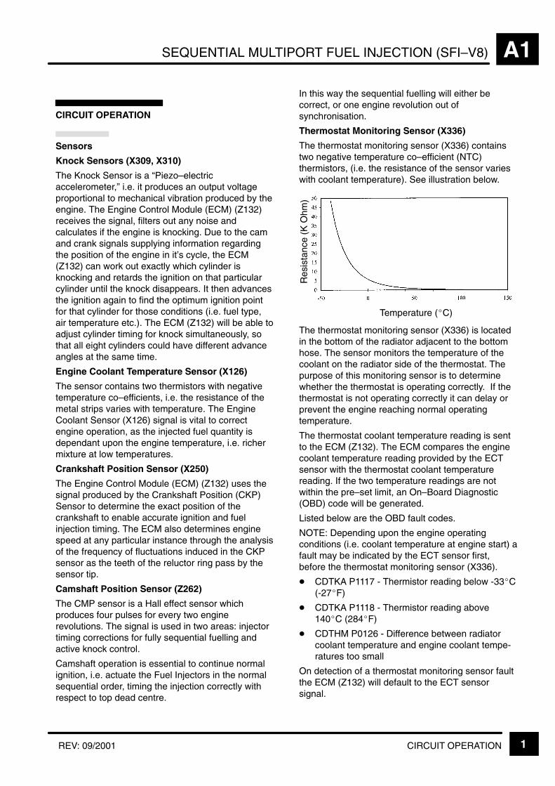
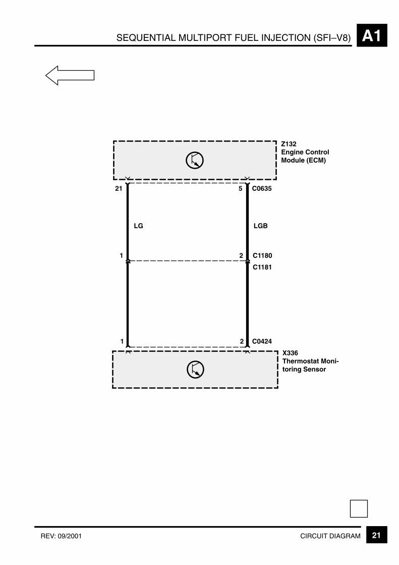
Thermostat Monitoring Sensor (X336)
The thermostat monitoring sensor (X336) containstwo negative temperature co–efficient (NTC)thermistors, (i.e. the resistance of the sensor varieswith coolant temperature). See illustration below.
Res
ista
nce
(K O
hm)
Temperature (C)
The thermostat monitoring sensor (X336) is locatedin the bottom of the radiator adjacent to the bottomhose. The sensor monitors the temperature of thecoolant on the radiator side of the thermostat. Thepurpose of this monitoring sensor is to determinewhether the thermostat is operating correctly. If thethermostat is not operating correctly it can delay orprevent the engine reaching normal operatingtemperature.
The thermostat coolant temperature reading is sentto the ECM (Z132). The ECM compares the enginecoolant temperature reading provided by the ECTsensor with the thermostat coolant temperaturereading. If the two temperature readings are notwithin the pre–set limit, an On–Board Diagnostic(OBD) code will be generated.
Listed below are the OBD fault codes.
NOTE: Depending upon the engine operatingconditions (i.e. coolant temperature at engine start) afault may be indicated by the ECT sensor first,before the thermostat monitoring sensor (X336).
CDTKA P1117 - Thermistor reading below -33C(-27F)
CDTKA P1118 - Thermistor reading above140C (284F)
CDTHM P0126 - Difference between radiatorcoolant temperature and engine coolant tempe-ratures too small
On detection of a thermostat monitoring sensor faultthe ECM (Z132) will default to the ECT sensorsignal.

SEQUENTIAL MULTIPORT FUEL INJECTION (SFI–V8)A1
CIRCUIT OPERATION2 REV: 09/2001
Mass Air Flow Sensor (X105)
The Mass Air Flow Sensor (X105) utilises a ‘hot film’element contained in the intake air tube to monitorthe mass flow of the air stream drawn into theengine. It contains two sensing elements: oneelement is controlled at ambient temperature, whilethe other is heated to 200 °C/ 390 °F above theambient temperature. The air flow passes the heatedelement and cools it down therefore lowering theresistance of the hot film element. In order tomaintain a constant temperature the circuit to theheated element has to supply more current. Themeasured air mass flow is used by the ECM (Z132)to determine fuel quantity to be injected in order tomaintain a storchiometric air/fuel mixture foroptimum engine performance and low emissions.
Throttle Position Sensor (X171)
This sensor is a variable resistor which determinesthrottle angle position and angular velocity. Thesignal is used by the ECM (Z132) to calculate fuelinjection duration under various operating conditions.The closed idle switch position is used for idle speedcontrol in conjunction with road speed. Failure of theThrottle Position Sensor (X171) will result in pooridle and lack of throttle response. If the ThrottlePosition Sensor (X171) fails in the “closed” mode,then the engine will only revolve up to 1740 rpmwhen the ECM (Z132) will initiate “over run fuelcut–off”.
Heated Oxygen Sensors (X139, X160, X289, X290)
The Heated Oxygen Sensor consists of a ceramicbody of zirconium and yttrium which is coated withgas–permeable platinum. If the sensor reachessufficiently high temperatures (above 350°C/660 °F)it generates a voltage which is proportional to theoxygen content in the exhaust stream in comparisonwith the ambient oxygen content. From this value theECM (Z132) can adjust the injected fuel quantity thatas to achieve the correct air/fuel ratio. This reducesthe emissions of Carbon Monoxide (CO),Hydrocarbons (HC) and oxides of Nitrogen (NOX) toacceptable levels.
Presently, two heated oxygen sensors are used, onein each exhaust down pipe just before the catalyst.
In the event of sensor failure, the system will defaultto ”open loop”. Operation and fuelling will becalculated using signals from the remaining ECMinputs. The fault is indicated by illumination of themalfunction indicator lamp (MIL). ECM diagnosticsalso uses heated oxygen sensors to detect catalystdamage, misfire and fuel system faults.
North American vehicles have two extra heatedoxygen sensors mounted one after each catalyst.
These are used to determine whether the catalystsare operating efficiently.
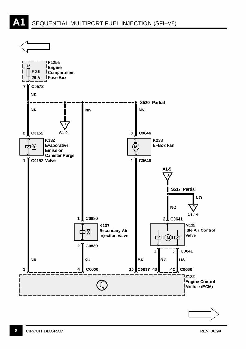
Idle Air Control Valve (M112)
The Idle Air Control Valve (M112) controls the idlespeed of the engine by moving the plunger a setdistance, known as a step. Fully open is zero stepsand fully closed is 180 steps. The motor moves eachstep by sequentially changing the polarity to each ofthe two coils.
SEQUENTIAL MULTIPORT FUEL INJECTION (SFI–V8) A1
CIRCUIT OPERATION 3REV: 11/2000
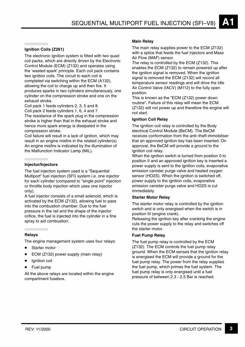
Ignition Coils (Z261)
The electronic ignition system is fitted with two quadcoil packs, which are directly driven by the ElectronicControl Module (ECM) (Z132) and operates usingthe ‘wasted spark’ principle. Each coil pack containstwo ignition coils. The circuit to each coil iscompleted via switching within the ECM (A132),allowing the coil to charge up and then fire. Itproduces sparks in two cylinders simultaneously, onecylinder on the compression stroke and one on theexhaust stroke.Coil pack 1 feeds cylinders 2, 3, 5 and 8.Coil pack 2 feeds cylinders 1, 6, 4 and 7.The resistance of the spark plug in the compressionstroke is higher than that in the exhaust stroke andhence more spark energy is dissipated in thecompression stroke. Coil failure will result in a lack of ignition, which mayresult in an engine misfire in the related cylinder(s). An engine misfire is indicated by the illumination ofthe Malfunction Indicator Lamp (MIL).
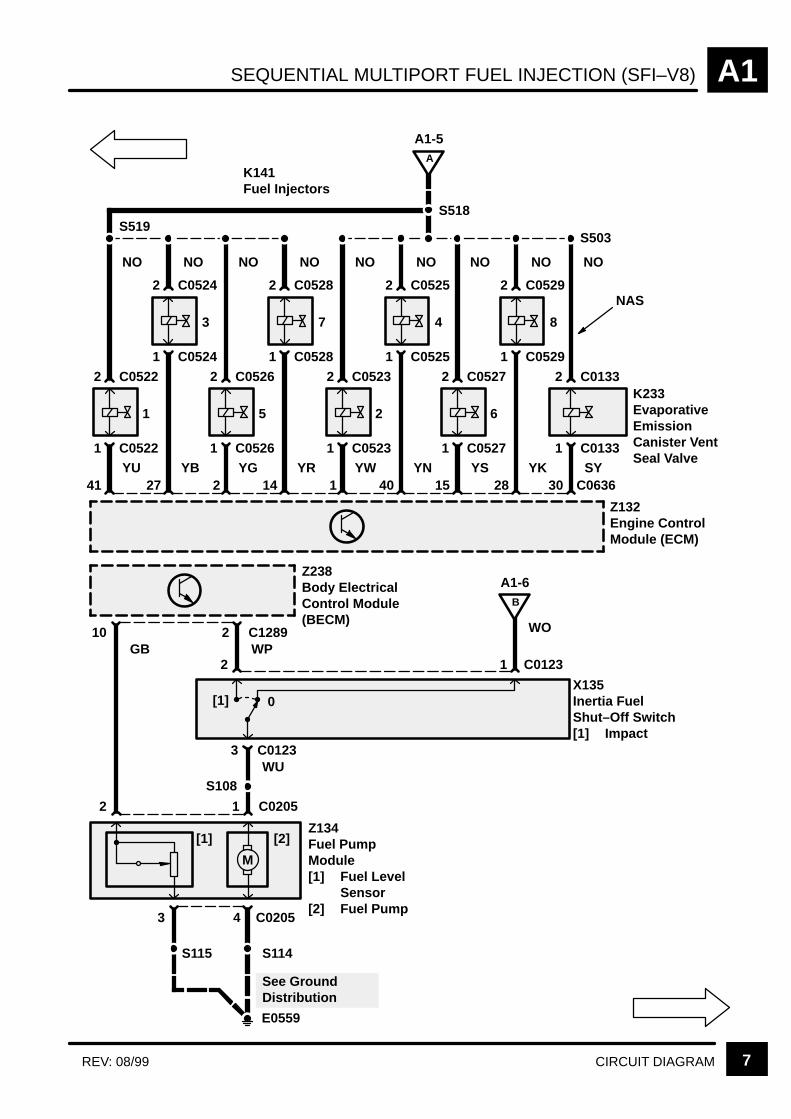
Injector/Injectors
The fuel injection system used is a ”SequentialMultiport” fuel injection (SFI) system i.e. one injectorfor each cylinder (compared to ”single point” injectionor throttle body injection which uses one injectoronly).A fuel injector consists of a small solenoid, which isactivated by the ECM (Z132), allowing fuel to passinto the combustion chamber. Due to the fuelpressure in the rail and the shape of the injectororifice, the fuel is injected into the cylinder in a finespray to aid combustion.
Relays
The engine management system uses four relays:
Starter motor
ECM (Z132) power supply (main relay)
Ignition coil
Fuel pump
All the above relays are located within the enginecompartment fusebox.
Main Relay
The main relay supplies power to the ECM (Z132)with a splice that feeds the fuel injectors and MassAir Flow (MAF) sensor. The relay is controlled by the ECM (Z132). Thisenables the ECM (Z132) to remain powered up afterthe ignition signal is removed. When the ignitionsignal is removed the ECM (Z132) will record alltemperature sensor readings and will drive the IdleAir Control Valve (IACV) (M112) to the fully openposition. This is known as the ”ECM (Z132) power downroutine”. Failure of this relay will mean the ECM(Z132) will not power up and therefore the engine willnot start.
Ignition Coil Relay
The ignition coil relay is controlled by the Bodyelectrical Control Module (BeCM). The BeCMreceives conformation from the anti–theft immobiliserthat an approved ignition key has been inserted. Onapproval, the BeCM will provide a ground to theignition coil relay. When the ignition switch is turned from position 0 toposition II and an approved ignition key is inserted apower supply is sent to the ignition coils, evaporativeemission canister purge valve and heated oxygensensor (HO2S). When the ignition is switched off,power supply to the ignition coils, evaporativeemission canister purge valve and HO2S is cutimmediately.
Starter Motor Relay
The starter motor relay is controlled by the ignitionswitch and is only energised when the switch is inposition III (engine crank). Releasing the ignition key after cranking the enginecuts the power supply to the relay and switches offthe starter motor.
Fuel Pump Relay
The fuel pump relay is controlled by the ECM(Z132). The ECM controls the fuel pump relayground. When the ECM senses that the ignition relayis energised the ECM will provide a ground for thefuel pump relay. The power from the relay suppliesthe fuel pump, which primes the fuel system. Thefuel pump relay is only energised until a fuelpressure of between 2.3 - 2.5 Bar is reached.
SEQUENTIAL MULTIPORT FUEL INJECTION (SFI–V8)A1
CIRCUIT OPERATION4 REV: 11/99
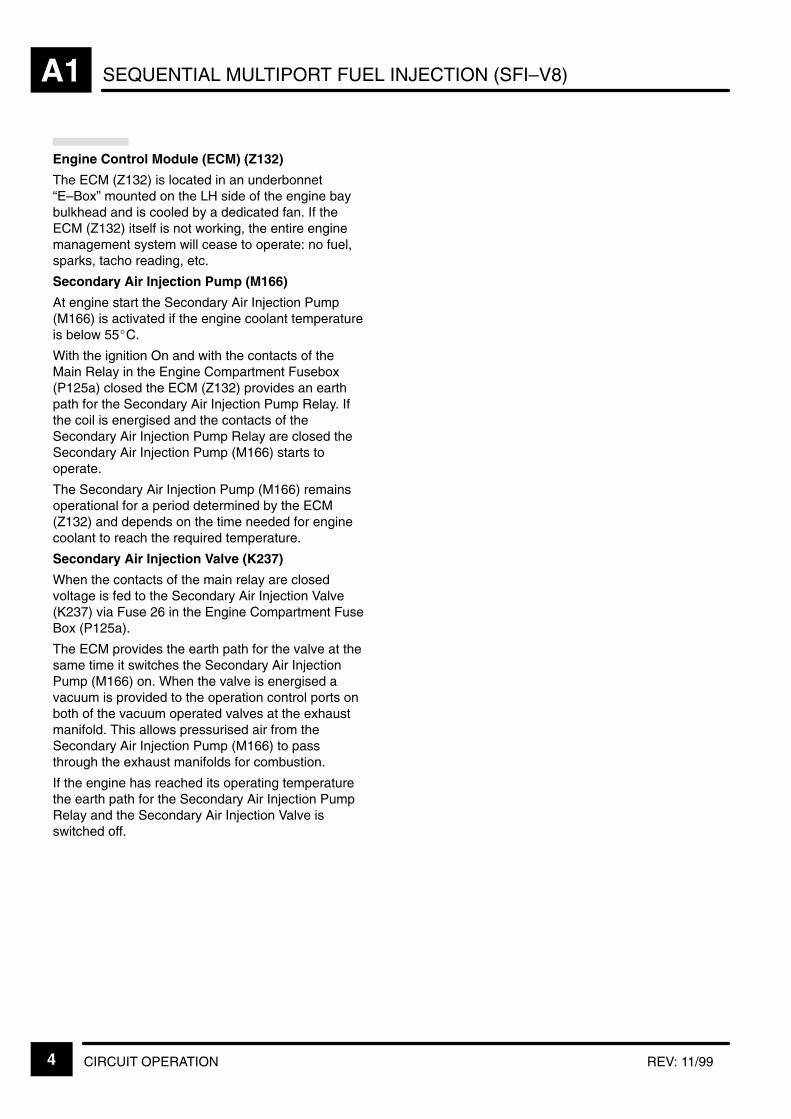
Engine Control Module (ECM) (Z132)
The ECM (Z132) is located in an underbonnet“E–Box” mounted on the LH side of the engine baybulkhead and is cooled by a dedicated fan. If theECM (Z132) itself is not working, the entire enginemanagement system will cease to operate: no fuel,sparks, tacho reading, etc.
Secondary Air Injection Pump (M166)
At engine start the Secondary Air Injection Pump(M166) is activated if the engine coolant temperatureis below 55C.
With the ignition On and with the contacts of theMain Relay in the Engine Compartment Fusebox(P125a) closed the ECM (Z132) provides an earthpath for the Secondary Air Injection Pump Relay. Ifthe coil is energised and the contacts of theSecondary Air Injection Pump Relay are closed theSecondary Air Injection Pump (M166) starts tooperate.
The Secondary Air Injection Pump (M166) remainsoperational for a period determined by the ECM(Z132) and depends on the time needed for enginecoolant to reach the required temperature.
Secondary Air Injection Valve (K237)
When the contacts of the main relay are closedvoltage is fed to the Secondary Air Injection Valve(K237) via Fuse 26 in the Engine Compartment FuseBox (P125a).
The ECM provides the earth path for the valve at thesame time it switches the Secondary Air InjectionPump (M166) on. When the valve is energised avacuum is provided to the operation control ports onboth of the vacuum operated valves at the exhaustmanifold. This allows pressurised air from theSecondary Air Injection Pump (M166) to passthrough the exhaust manifolds for combustion.
If the engine has reached its operating temperaturethe earth path for the Secondary Air Injection PumpRelay and the Secondary Air Injection Valve isswitched off.
SEQUENTIAL MULTIPORT FUEL INJECTION (SFI–V8) A1
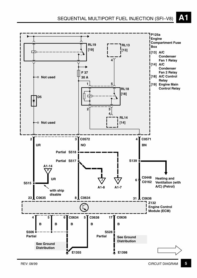
5CIRCUIT DIAGRAMREV: 08/99
P125aEngineCompartment FuseBox
[13] A/CCondenserFan 1 Relay
[14] A/CCondenserFan 2 Relay
[18] A/C ControlRelay
[19] Engine MainControl Relay
RL19
[19]
Not used
RL18
[18]
3
1 5
4RL14
[14]
2 3 4 C0571
RL13
[13]
4
Not used
Z132Engine ControlModule (ECM)
See GroundDistribution
S528S506
23 8 C0634 31 C0636
5 C063656 17
B
J
A1-8
UR
B B B
2
S517
S515
F
A1-14
UR
with shipdisable
BN
C0572
NO
A
F 3730 A
6C0448
S139
Heating andVentilation (withA/C) (Petrol)
4
B
E1355
PartialPartial
D5
C0635
A1-7
C0162
C0634
See GroundDistribution
C0638
E1398
S518Partial
Partial
SEQUENTIAL MULTIPORT FUEL INJECTION (SFI–V8)A1
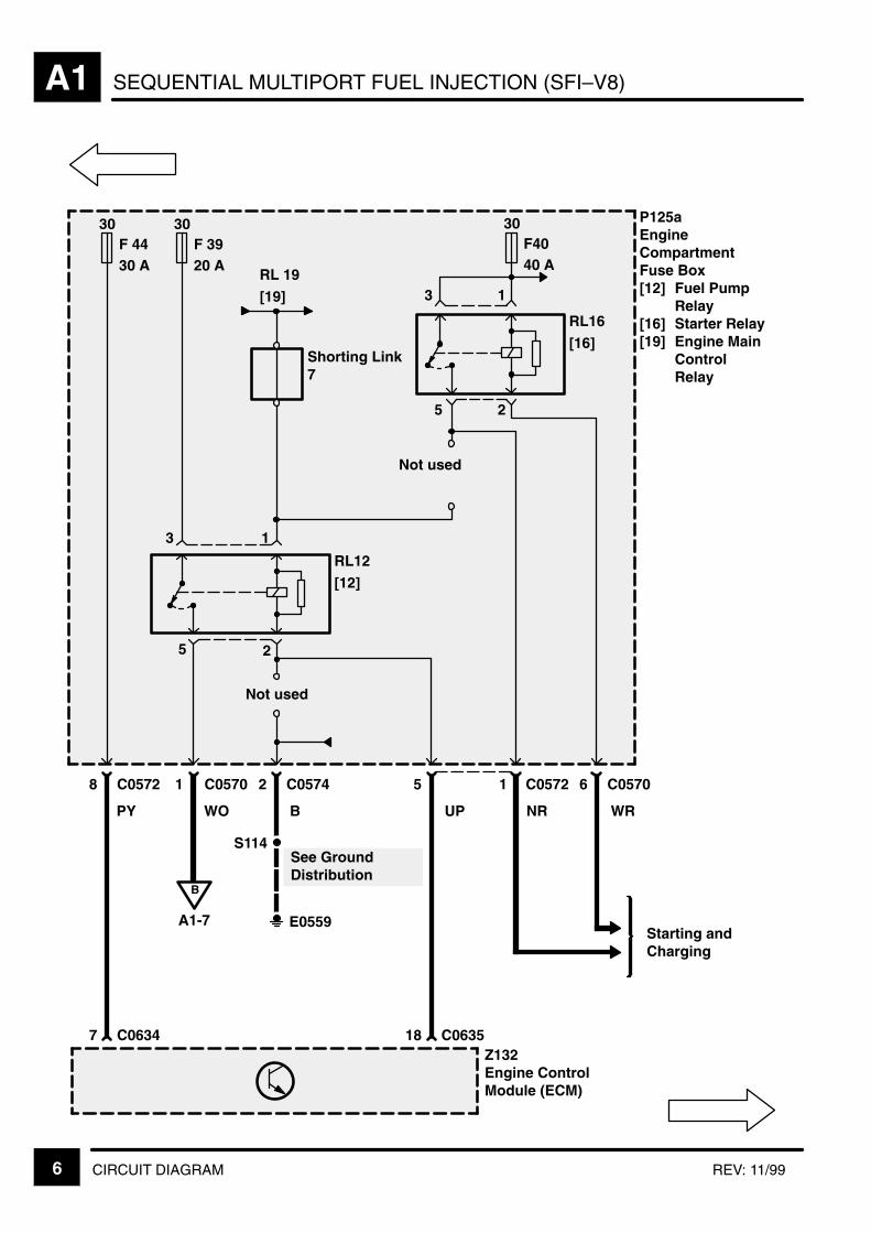
6 CIRCUIT DIAGRAM REV: 11/99
Shorting Link7
30F 3920 A
B
A1-7
RL 19
[19]
30F4040 A
P125aEngineCompartmentFuse Box[12] Fuel Pump
Relay[16] Starter Relay[19] Engine Main
ControlRelay
Starting andCharging
Z132Engine ControlModule (ECM)
Not used
See GroundDistribution
Not used
RL16
[16]
RL12
[12]
E0559
3 1
5 2
1 C0570 2 C0574
3 1
WO
5 2
5 1 C0572 6 C0570
UP NR WR
18 C0635
B
S114
7 C0634
8 C0572
PY
30F 4430 A
SEQUENTIAL MULTIPORT FUEL INJECTION (SFI–V8) A1
7CIRCUIT DIAGRAMREV: 08/99
2 1 C0205
Z132Engine ControlModule (ECM)
2 C0522
1 C0522
1
2 C0524
1 C0524
3
NO NO
YU
B
A1-6
X135Inertia FuelShut–Off Switch[1] Impact
Z238Body ElectricalControl Module(BECM)
Z134Fuel PumpModule[1] Fuel Level
Sensor[2] Fuel Pump
2741
2 C0526
1 C0526
5
2 C0528
1 C0528
7
NO NO
14
2 C0523
1 C0523
2
2 C0525
1 C0525
4
NO NO
40
2 C0527
1 C0527
6
2 C0529
1 C0529
8
NO NO
28YB YG YR YW YN YKYS
C06362 1 15
WP10 C12892
GB
WUC01233
E0559
2 1 C0123
3 4 C0205
[1] 0
See GroundDistribution
S503
K141Fuel Injectors
WO
2 C0133
1 C0133
NO
SY30
K233EvaporativeEmissionCanister VentSeal Valve
S518S519
S108
NAS
A
A1-5
M
[1] [2]
S115 S114
SEQUENTIAL MULTIPORT FUEL INJECTION (SFI–V8)A1
8 CIRCUIT DIAGRAM REV: 08/99
K132EvaporativeEmissionCanister PurgeValve
15F 2620 A
1 C0152
2 C0152
K238E–Box Fan
1 C0646
3 C0646
3 10 C0637
I
A1-9
S517
M
3 C0641
43 C0636
S520
7 C0572
NK
NK
NR
NK
BK
Partial
NO
M112Idle Air ControlValve
1
RG US
Z132Engine ControlModule (ECM)
42
C06412
C
A1-19
J
A1-5
P125aEngineCompartmentFuse Box
Partial
M
NO
NK
K237Secondary AirInjection Valve
2 C0880
1 C0880
4 C0636
KU
SEQUENTIAL MULTIPORT FUEL INJECTION (SFI–V8) A1
9CIRCUIT DIAGRAMREV: 08/99
1 4 C0149
R UG
X105Mass Air FlowSensor
52
Z132Engine ControlModule (ECM)
Z262CamshaftPosition Sensor
C01762
A1-8
S520Partial
3
1 C0176
S528 Partial
E1398
B
See GroundDistribution
34 7 C06362320
C06369
C01493
SU SLG
Z132Engine ControlModule (ECM)
SequentialMultiport FuelInjection (SFI–V8)
S509
NK
I
NK NK
RB
SEQUENTIAL MULTIPORT FUEL INJECTION (SFI–V8)A1
10 CIRCUIT DIAGRAM REV: 08/99
Z132Engine ControlModule (ECM)
X250CrankshaftPosition Sensor
Z202CrankshaftPosition SensorShield
BY
32
X295Left KnockSensor
1 C0627
2 C0627
KW
B
Z264Left Knock SensorShield
Z264Left Knock SensorShield
36 C0636
X296Right KnockSensor
1 C0626
2 C0626
Z265Right KnockSensor Shield
Z265Right KnockSensor Shield
49
B
S522
48
Z132Engine ControlModule (ECM)
KB
2
Z202CrankshaftPosition SensorShield
S523
4645 35 C0636
S524
1
3
KB B B
C0168P
C0168P

SEQUENTIAL MULTIPORT FUEL INJECTION (SFI–V8) A1
11CIRCUIT DIAGRAMREV: 08/99
Z132Engine ControlModule (ECM)
10 24 C0636
X171Throttle PositionSensor
Z132Engine ControlModule (ECM)
2 C0175
R YLG
S506
E1355
GU
G
Warnings andIndicators
22
2 C0196P4
X126Engine CoolantTemperatureSensor
1 C0196P3
RB B
See Fuse Details
21 25 C0636
3 C01751
RB
Instruments

SEQUENTIAL MULTIPORT FUEL INJECTION (SFI–V8)A1
12 CIRCUIT DIAGRAM REV: 08/99
15F 2620 A
S509
P125aEngineCompartmentFuse Box
7 C0572
See Fuse Details
4 C0644
3 1 2 C0644
WO RB O
19 9 15
X139Left HeatedOxygen Sensor
4 C0645
1 2 3 C0645
10 16 13
X160Right HeatedOxygen Sensor
Z132Engine ControlModule (ECM)
Partial
S528 Partial
C0635
NK
Z193Left HeatedOxygen SensorShield
Z194Right HeatedOxygen SensorShield
NK
E1398
See GroundDistribution
WORB U
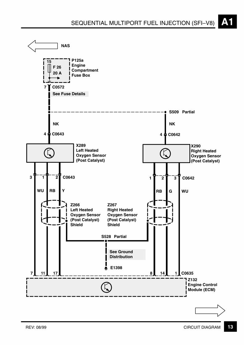
SEQUENTIAL MULTIPORT FUEL INJECTION (SFI–V8) A1
13CIRCUIT DIAGRAMREV: 08/99
15F 2620 A
S509
P125aEngineCompartmentFuse Box
7 C0572
See Fuse Details
4 C0643
3 1 2 C0643
WU RB Y
7 11 17
X289Left HeatedOxygen Sensor(Post Catalyst)
4 C0642
1 2 3 C0642
RB G WU
8 14 1
X290Right HeatedOxygen Sensor(Post Catalyst)
Z132Engine ControlModule (ECM)
Partial
S528 Partial
C0635
NK
Z266Left HeatedOxygen Sensor(Post Catalyst)Shield
Z267Right HeatedOxygen Sensor(Post Catalyst)Shield
NK
NAS
E1398
See GroundDistribution
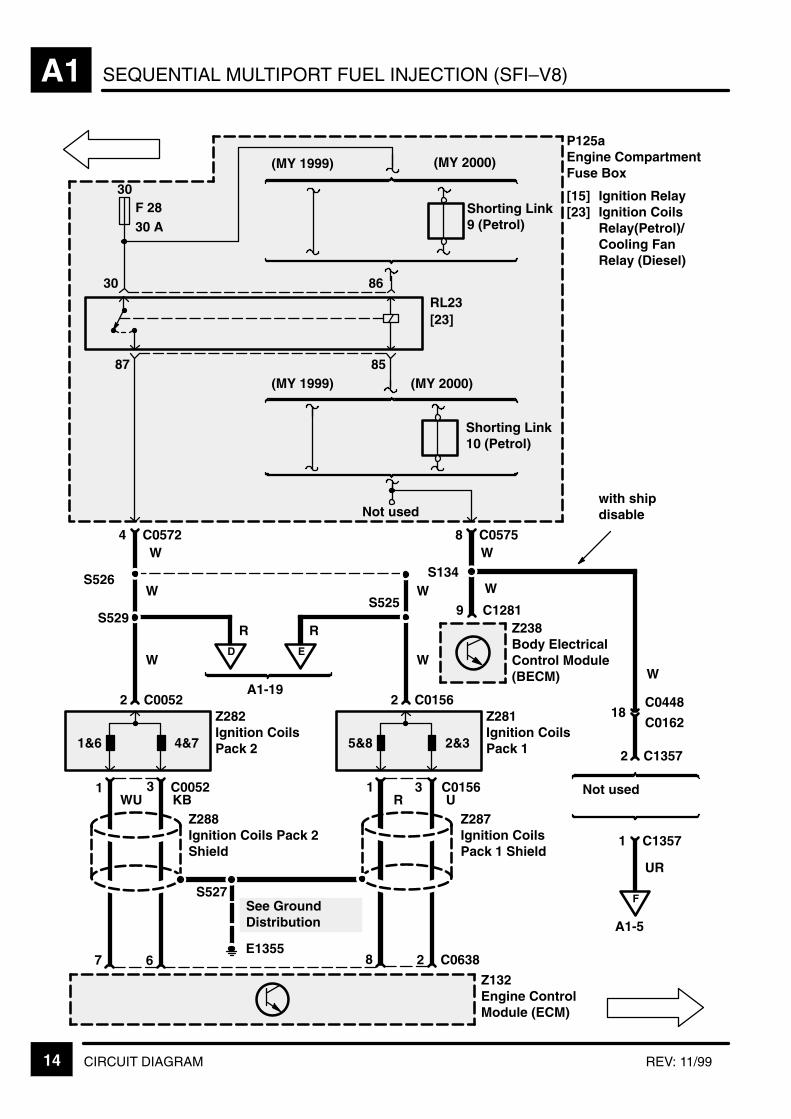
SEQUENTIAL MULTIPORT FUEL INJECTION (SFI–V8)A1
14 CIRCUIT DIAGRAM REV: 11/99
P125aEngine CompartmentFuse Box
[15] Ignition Relay[23] Ignition Coils
Relay(Petrol)/Cooling FanRelay (Diesel)
4 C0572
Z282Ignition CoilsPack 2
W
2 C1357
2 C0052
S526
1 C1357
Not used
UR
18C0448
C0162
F
A1-5
30F 2830 A
RL23[23]
8 C0575
1&6 4&7
Z281Ignition CoilsPack 1
2 C0156
5&8 2&3
S134W
W
9 C1281Z238Body ElectricalControl Module(BECM)
3 C00521
67
3 C01561
2 C06388
S527See GroundDistribution
E1355
WU KB
87 85
30 86
Not used
W
Z132Engine ControlModule (ECM)
R U
with shipdisable
S529
D
A1-19
E
S525W
Z288Ignition Coils Pack 2Shield
Z287Ignition CoilsPack 1 Shield
WW
R R
W
(MY 2000)(MY 1999)
Shorting Link10 (Petrol)
Shorting Link9 (Petrol)
(MY 2000)(MY 1999)

SEQUENTIAL MULTIPORT FUEL INJECTION (SFI–V8) A1
15CIRCUIT DIAGRAMREV: 08/2002
X320Fuel Tank Pres-sure Sensor
GK
9 C01628C0448
2 C01321
3 C0132
RBR
7C0448C0162
Z132Engine ControlModule (ECM)
C06386
NAS
Z132Engine ControlModule (ECM)
C06379
15
MF250 A
B
S114
C063616
10 C0448
C063714
RL10[10]
2 5
1 3 4
1 C0573 2 C0574
P125aEngine Compart-ment Fuse Box
[10] SecondaryAir InjectionPump Relay
C0162
NG
See Fuse Details
R
2 C0575
M166Secondary Air In-jection PumpM
1 C0879
E0563
B
2 C0879
E0559

SEQUENTIAL MULTIPORT FUEL INJECTION (SFI–V8)A1
16 CIRCUIT DIAGRAM REV: 08/99
Z132Engine ControlModule (ECM)
4 C1584
16
17
15
7 C0040
34 C0637
32 C0637
K
C0162C0448
C0067C0229
X318Data LinkConnector(OBDII)
Z108Anti–Lock BrakeSystem ECU
C0504 RHDLHD
C0448C0162
YK
Data LinkConnector
K
KR
S214

SEQUENTIAL MULTIPORT FUEL INJECTION (SFI–V8) A1
17CIRCUIT DIAGRAMREV: 08/99
Z238Body ElectricalControl Module(BECM)
Z132Engine ControlModule (ECM)
Z165Air SuspensionECU
30 C0867
22
YB
S104
14C0448C0162
13 C1288
22
36
12 33 2017
WU
5 C1289
GB
16
B
5
S
9 C1288
C0637
Y
C0162C0448
UN
13
Z256Transfer GearBox ECU
C131928
8 C0637
21
YN
37
Z255Auto Gear BoxControl Unit
16 C132044
2C0868C09031
2 C08681
152013
C0448C0162
AutomaticTransmission
ManualTransmission
Not used
3C0868C0903
Z108Anti–Lock BrakeSystem ECU
C1584C0504
LHDRHD
11 C1289
3
YG
1
1
11
C1281
C0634
W
15F 710 A
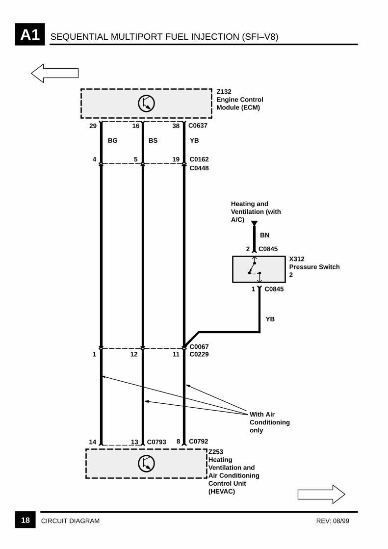
SEQUENTIAL MULTIPORT FUEL INJECTION (SFI–V8)A1
18 CIRCUIT DIAGRAM REV: 08/99
Z132Engine ControlModule (ECM)
Z253HeatingVentilation andAir ConditioningControl Unit(HEVAC)
X312Pressure Switch2
4
29
14
38
13 C0793
1 C0845
BG BS YB
5 19
1 12 11
YB
With AirConditioningonly
2 C0845
16 C0637
C0448C0162
Heating andVentilation (withA/C)
BN
C0229C0067
8 C0792
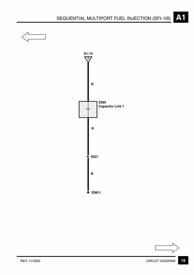
SEQUENTIAL MULTIPORT FUEL INJECTION (SFI–V8) A1
19CIRCUIT DIAGRAMREV: 11/2000
Z285Capacitor Link 1
R
E0811
R
D
A1-14
S521
B
SEQUENTIAL MULTIPORT FUEL INJECTION (SFI–V8)A1
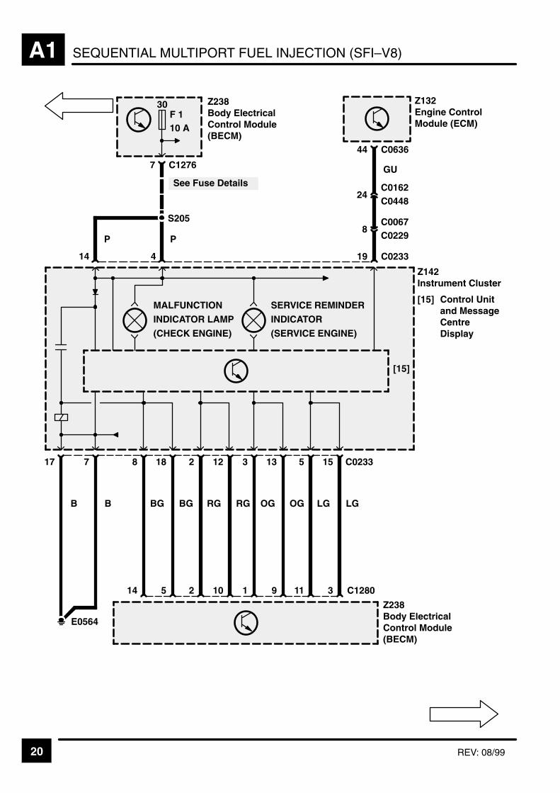
20 REV: 08/99
30F 110 A
Z238Body ElectricalControl Module(BECM)
See Fuse Details
44 C0636
7 C1276
Z132Engine ControlModule (ECM)
S205
24C0162
GU
C0448
8C0067C0229
19 C0233414
Z142Instrument Cluster
[15] Control Unitand MessageCentreDisplay
15 C023351331221887
LG
3 C1280
LG
11
OG
9
OG
1
RG
10
RG
2
BG
5
BG
14
B
E0564
Z238Body ElectricalControl Module(BECM)
[15]
PP
17
B
MALFUNCTION
INDICATOR LAMP
(CHECK ENGINE)
SERVICE REMINDER
INDICATOR
(SERVICE ENGINE)
SEQUENTIAL MULTIPORT FUEL INJECTION (SFI–V8) A1
21CIRCUIT DIAGRAMREV: 09/2001
LG
21
LGB
5 C0635
Z132Engine ControlModule (ECM)
X336Thermostat Moni-toring Sensor
1 2 C1180
C1181
1 2 C0424

KEY INFORMATIONi
"
"
(
(
(
&0'!
'-&
08'0;'
=+ # 9 0
000
>+ # 9 #
*= # 9 0
00 000
& # 9 0
07 00
>* 8
0&-0 08&
5 6
5 6
;# "
0 #
7 #
&9
(
08';0
0 # 9
1 & ;
1 & %
#
1 #
1 ? # 7
0 56
#
DIESEL A6
CIRCUIT OPERATION 1
CIRCUIT OPERATION
Sensors
Engine Speed Sensor (X255)
The engine speed signal is crucial to the system, asthe information from the sensor is used in virtually allof the strategies within the ‘DDE’ (Digital DieselElectronics) and its Engine Control Module (ECM)(Z132). Through this sensor, the ECM (Z132) knowsif the engine is turning, how fast it is turning andapproximately where the engine is in its cycle. Thesensor is of the ‘Hall effect’ type, which sends out apulse to the ECM (Z132) every time a ‘tooth’ issensed on the flywheel (the flywheel has six ‘teeth’).If the sensor fails, then the warning lamp is activatedand the ECM (Z132) enters a ‘limp home’ modewhere the ECM (Z132) looks at the signal from theneedle lift sensor in one of the injectors. The needlelift sensor gives one pulse per injection, i.e. onepulse per twelve engine speed sensor pulses. Theresponse of the ECM (Z132) to changes in engineparameters will, therefore, be considerably slower,and a higher idle speed is initiated to try tocompensate at low engine speeds.
Needle Lift Sensor (X318)
The engine has six diesel fuel injectors, one of whichhas a sensing element at the tip which informs theECM (Z132) exactly when the injector fires (the‘beginning of injection’ signal). The ECM (Z132) usesthis to correct the injection timing and also to backup the engine speed signal in case that sensor fails.If this sensor fails, the warning lamp will switch onand the vehicle will enter ‘limp home’ mode withreduced engine power/performance and lack ofthrottle response (as there is a lack of feedback onthe injection timing).
Engine Coolant Temperature Sensor (X126)
This sensor is a ‘thermistor’ (a temperaturedependent resistor) where the voltage output variesin proportion to coolant temperature. The ECM(Z132) uses this information in many strategies, i.e.to correct the injected fuel quantity and timing(especially during cold starts), length of glow plugtiming, etc. The sensor is located in the top of theengine block. In case of a failure, the warning lampis not activated and the ECM (Z132) selects asubstitute value of 50C for glow plug and ignitiontiming and uses the fuel temperature to correct thefuel quantity, glow plug timing will not be correct,possibly resulting in long crank times in cold weather
as well as slight fuelling effects. These symptomsmay not be noticeable.
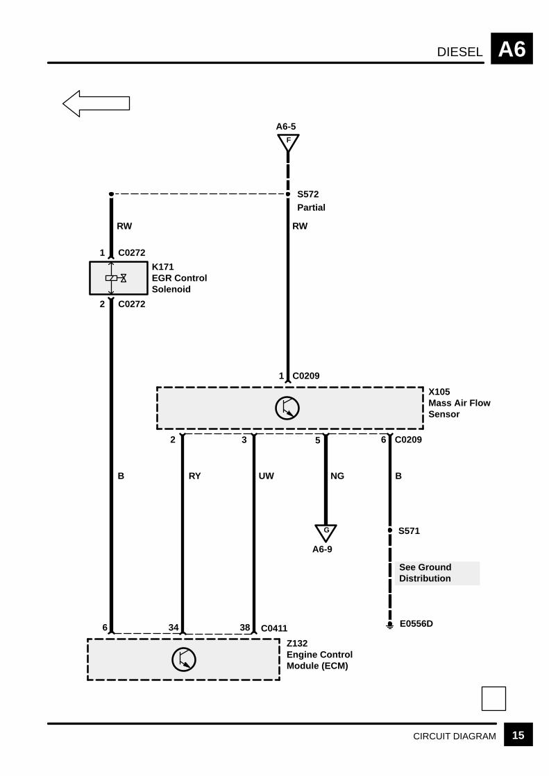
Mass Air Flow Sensor (X105)
The Mass Air Flow Sensor (X105) is a hot filmsensor which has a heated surface maintained by anelectrical current at a constant temperature. Withcool air flowing past the sensor, the volume of airdrawn into the intake manifold is measured by theelectrical current required to keep the temperature ofthe hot film sensor constant. This data is used tocalculate the injected fuel volume and the rate ofExhaust Gas Recirculation (EGR).
The intake air temperature is measured by athermistor with a negative temperature co–efficientand measures the actual temperature of the turbobooster air entering the engine. The ECM (Z132)uses this information, in conjunction with themanifold absolute pressure sensor, to determine thevolume of air being drawn into the engine.
DIESELA6
CIRCUIT OPERATION2
Boost Pressure Sensor
The boost pressure sensor signal is used inconjunction with the air temperature signal tocalculate volume air flow into the engine. The sensoris located on the rear bulkhead, with the pressuretap just after the charge air cooler. If the sensor fails,a substitute value of 490 hPa is used by the ECM(Z132), producing a reduction in power due to a fuelquantity limiting to 21mg/stroke.
Throttle Position Sensor (X171)
The DDE system is a ‘Drive by Wire’ system i.e. thethrottle pedal does not directly control a throttle discor the amount of fuel injected into the engine, butaccelerator movements or ‘drivers request’ aresensed and the information is passed to the ECM(Z132). The ECM (Z132) calculates the maximumallowable fuel quantity from the air flow into theengine, engine speed, temperature, etc. It alsoincludes information from strategies such as smokelimitation, active surge damping, automatic gearchange, fuel reduction, etc. to calculate the finalfigure. When driving, if the ‘drivers request’ signal issmaller than the maximum allowable quantity, thenthe requested quantity is injected. However, if therequested quantity is greater than the maximumallowable, then the latter quantity is injected ratherthan the driver’s demand. Therefore the ThrottlePosition Sensor (X171) is very important to thesystem. It is located within the cab, close to thepedal assembly itself. The unit consists of apotentiometer and has three outputs:
1. Throttle Position – pin 37 ECM (Z132)
The sensor outputs the pedal position to the ECM(Z132), which uses the information as describedabove.
2. Idle Position Switch – pin 25 ECM (Z132).
The sensor has a separate idle position switch whichinforms the ECM (Z132) of the pedal status in theform of a simple on/off signal. This information isused by the ECM (Z132) to implement idle speedcontrol’ and other strategies i.e. overrun fuelshut–off’.
3. Kick Down Switch.
This switch is currently not used.
Fuel Temperature Sensor
A thermistor is also located inside the injectionpump. The fuel temperature sensor signal is used toadjust the quantity of injected fuel, especially duringtemperature extremes. The signal is also used toback up the Engine Coolant Temperature Sensor(X126). If this sensor fails, the ECM (Z132) uses a
substitute value of 60C and only slight effects onfuelling may possibly be noted.
Fuel Quantity Feedback Sensor
Located within the injection pump, this sensor sendsthe ECM (Z132) information regarding the actualquantity of fuel injected. Failure of the sensor orcorrupted signals will illuminate the warning lampand cause the engine to stall or not start. A secondcheck, a plausibility check against the needle liftsensor, also takes place.
DIESEL A6
CIRCUIT OPERATION 3
Fuel Quantity Actuator
Once again located within the injection pump, this isa moving magnet actuator, failure of which will causethe engine to stall or not start as the ECM (Z132) willactivate the Fuel Shut–Off Solenoid (K111).
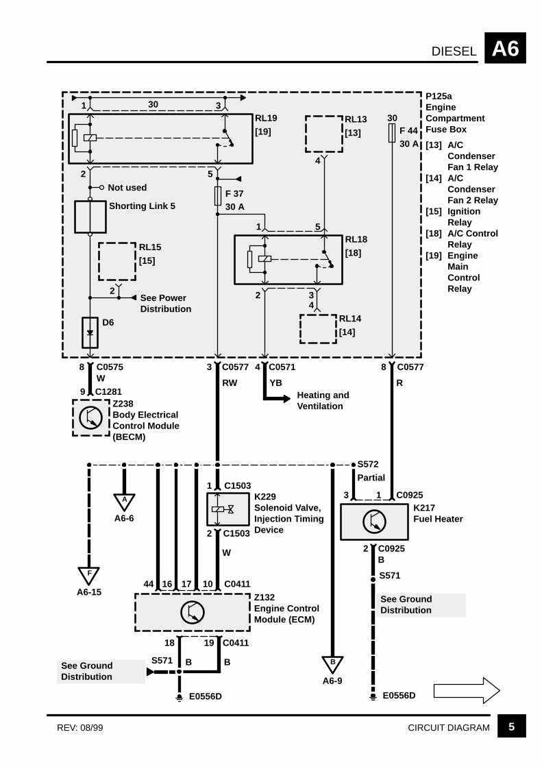
Injection Timing (Solenoid Valve Injection TimingDevice (K229))
This is another actuator within the injection pump.The ECM (Z132) receives a signal from the needlelift sensor and attempts to correct the injection timingaccordingly. If a change does not occur, then theECM (Z132) assumes a fault exists, activates thewarning lamp and reduces the quantity of injectedfuel.
Fuel Shut–Off Solenoid (K111)
The Fuel Shut–Off Solenoid (K111) shuts the enginedown if the ECM (Z132) detects a major fault.Failure of the valve itself does not activate thewarning lamp, although if a short circuit occurs, theengine will shut down.
Cruise Control
Due to the DDE system being drive by wire’, acruise control feature is supplied in the ECM (Z132)itself. Activation is via the steering wheel switches toa converter box and on a single line to the ECM(Z132). Failure of the signal results in cruise controlnot working.
Brake Switches
The ECM (Z132) has two brake inputs, each ofopposite polarity. Comparison of the polarity statesprovides the ECM (Z132) with a brake sense (i.e. ifswitch 1 high and switch 2 low going to switch 1 lowand switch 2 high) and so cancels cruise control. Ifboth switches are the same polarity, the ECM (Z132)senses a fault and does not allow cruise control.
Vehicle Speed Signal
The ECM (Z132) takes this signal from theAnti–Lock Brake System ECU (Z108) and uses theinformation for cruise control and active surgedamping’. Failure of the signal results in cruisedisallowed and temporary lack of surge damping (i.e.hard acceleration will cause the vehicle to surgeslightly). After 10 sec. a substitute value of 150 km/h
is used. Surging will reduce so as to be hardlynoticeable.
Theft Alarm
The ECM (Z132) has a simple on/off input regardingthe theft alarm. The ECM (Z132) will not allow theengine to start once activated and will kill the engineif activated up to 300 RPM (programmable). Over300 RPM, the engine is unaffected.
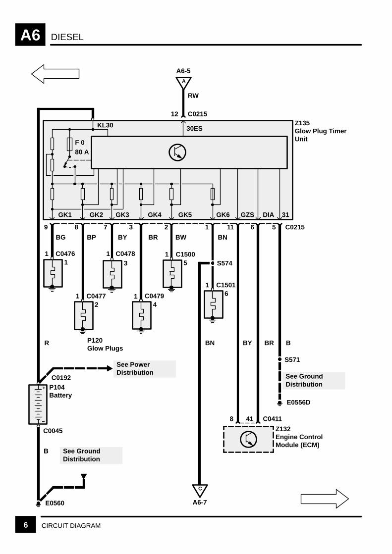
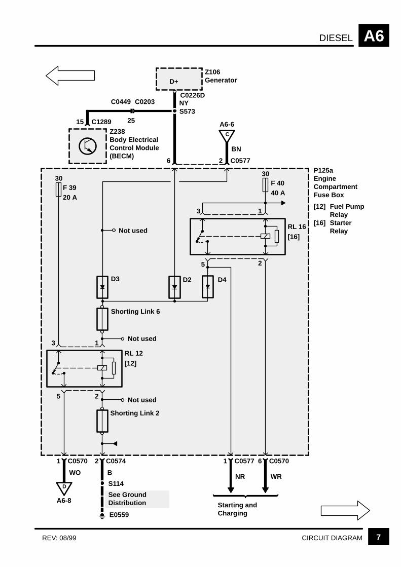
Relays
The DDE engine management system on the dieselvehicles uses four relays:
ECM (Z132) power supply (main relay), glow plugrelay, starter motor relay and fuel pump relay. Twoare located in the fuse box and two in the ECM(Z132) box behind the battery.

DIESELA6
CIRCUIT OPERATION4
Main Relay
Located in the ECM (Z132) box, this relay suppliesthe power feed to the ECM (Z132). It is controlled viathe Ignition Switch (X274) in position II.
Glow Plug Relay (Z135)
The Glow Plug Relay (Z135) takes a feed directlyfrom the battery and, on initialisation via the ECM(Z132), supplies current to each of the six glow plugs(one per cylinder) to aid cold starting. The glow timeis controlled via the ECM (Z132) which also monitorsthe relay and illuminates the glow plug indicator lampfor the duration of the glow time. This relay isrelatively large and is located with the main relaynext to the ECM (Z132).
Starter Motor Relay
This relay is also ignition key controlled, activatedwith the key in the ignition III position only. Releasingthe key after cranking cuts supply to the relay andswitches off the starter motor.
Fuel Pump Relay
The fuel pump relay is pulled in when the startermotor is activated, the earth path provided by thealternator output. When the engine is running, thestarter motor is deactivated, supplying an earth pathwhile the generator supplies a feed i.e. a polarityreversal.
ECM (Z132)
If the ECM (Z132) itself is not working, the entireengine management system will cease to operate,i.e. no fuel, tacho reading, etc.
DIESEL A6
5CIRCUIT DIAGRAMREV: 08/99
RL13
[13]
P125aEngineCompartmentFuse Box
[13] A/CCondenserFan 1 Relay
[14] A/CCondenserFan 2 Relay
[15] IgnitionRelay
[18] A/C ControlRelay
[19] EngineMainControlRelay
RL19
[19]
Not used
Shorting Link 5
2
RL15
[15]
5
2
1 3
RL18
[18]
3
1 5
4RL14
[14]
8 C0575 3 C0577 4 C0571
30F 4430 A
8 C0577
4
Z238Body ElectricalControl Module(BECM)
9 C1281W RW
Heating andVentilation
YB
S572
E0556D
A
A6-6
1 C1503
2 C1503
K229Solenoid Valve,Injection TimingDevice
W
10 C0411Z132Engine ControlModule (ECM)
171644
B
A6-9
K217Fuel Heater
1 C09253
2 C0925
R
S571
B
See GroundDistribution
18
E0556D
See GroundDistribution
19 C0411
B B
2
F
A6-15
Partial
F 3730 A
D6
See PowerDistribution
30
S571
DIESELA6
6 CIRCUIT DIAGRAM
See GroundDistribution
A
A6-5
See GroundDistribution
C
A6-7
E0556D
F 080 A
RW
12 C0215
1
9
2
8
3
7
4
3
5
2
6
1
S574
11 6 5 C0215
S571
E0560
41 C04118
Z132Engine ControlModule (ECM)
P104Battery
Z135Glow Plug TimerUnit
See PowerDistribution
GK1 GK2 GK3 GK4 GK5 GZS DIA 31
P120Glow Plugs
KL30 30ES
BG BP BY BR BW BN
BBRBYBNR
B
GK6
1 C0476
1 C0477
1 C0478
1 C0479
1 C1500
1 C1501
C0192
C0045
DIESEL A6
7CIRCUIT DIAGRAMREV: 08/99
30F 3920 A
S114D
A6-8See GroundDistribution
Z238Body ElectricalControl Module(BECM)
C
A6-615 C1289
D+
NYS573
C0203C0449
25
BN
2 C05776
Z106Generator
1 C0570
5 2
Shorting Link 2
E0559
WO B
2 C0574
RL 12
[12]
3 1
5 2
RL 16
[16]
3 1
30F 4040 A
D3
1 C0577 6 C0570
NR WR
Starting andCharging
P125aEngineCompartmentFuse Box
[12] Fuel PumpRelay
[16] StarterRelay
Shorting Link 6
Not used
Not used
D2 D4
C0226D
Not used

DIESELA6
8 CIRCUIT DIAGRAM
2 C1289
M
[1] [2]Z134Fuel Pump Module
[1] Fuel Level Sensor[2] Fuel Pump
[1] 0
WP
2
3 C0123
WU
4 C0204
GB
Z238Body ElectricalControl Module(BECM)
1
3 C02042
WO
D
A6-7
1 C0123
X135Inertia FuelShut–Off Switch
[1] Impact
See GroundDistributionE0559
10
42
PR
Z132Engine ControlModule (ECM)
27
16
GRData LinkConnector
17C0203C0448KR
LG
K
Data LinkConnector
15 C006716C0229
LGR
KR
S214 7
C0040
S213 15
LGR
LGR
X318Data LinkConnector(OBDII)
3 C0411
G
1 C0198K111Fuel Shut–OffSolenoid
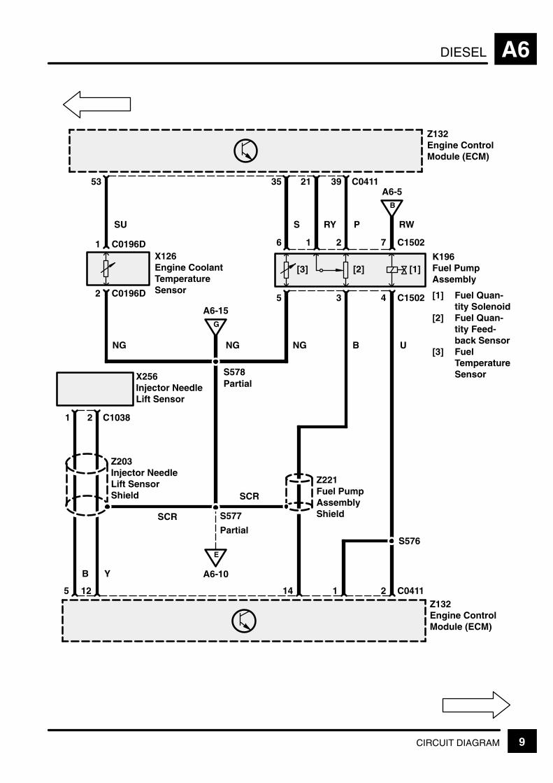
DIESEL A6
9CIRCUIT DIAGRAM
E
A6-10
B
A6-5
Z132Engine ControlModule (ECM)
K196Fuel PumpAssembly
[1] Fuel Quan-tity Solenoid
[2] Fuel Quan-tity Feed-back Sensor
[3] FuelTemperatureSensor
[3] [2] [1]
RW
7 C1502216
4 C150235
Z132Engine ControlModule (ECM)
392135 C0411
PRY
1 C0196D
2 C0196D
X126Engine CoolantTemperatureSensor
53
Y
12
B
5
SSU
2 C10381
X256Injector NeedleLift Sensor
Z203Injector NeedleLift SensorShield
SCR
S578
S577
21 C0411
S576
NG NG B U
14
Z221Fuel PumpAssemblyShield
Partial
SCR
G
A6-15
NG
Partial

DIESELA6
10 CIRCUIT DIAGRAM REV: 11/99
Z132Engine ControlModule (ECM)
Z132Engine ControlModule (ECM)
E
A6-9
K W S G
N Y
YS W SW
6512
Not used
YS W SW
C0203
C0448
1089
C0411253733
+
–0 0
[1] [2]
C0787LC0787R
84RHDLHD
NG NC0448C0203711
Z204Engine SpeedSensor Shield
X255Engine SpeedSensor
47B
C0168D1
C0168D2
Z204Engine SpeedSensor Shield
W UY5451
C021613
C02162
X253Boost PressureSensor
NG
S577Partial
Y
SCR
C041113E0556D
S571See GroundDistribution
B
X171Throttle PositionSensor
[1] PedalPosition > 9
[2] KickdownSwitch
C0787L
C0787R
LHD
RHD
DIESEL A6
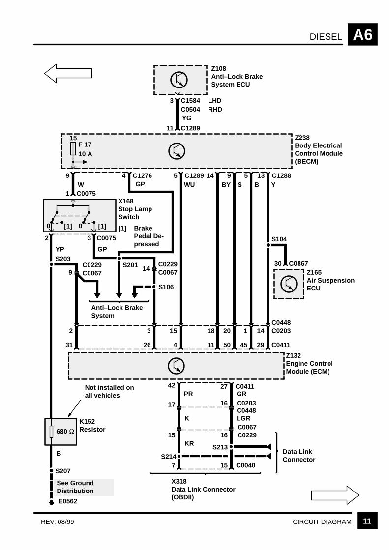
11CIRCUIT DIAGRAMREV: 08/99
W
15F 1710 A
0 [1]
S104
E0562
680
Z238Body ElectricalControl Module(BECM)
YG
30 C0867
3 C1584C0504
11 C1289
LHDRHD
Z108Anti–Lock BrakeSystem ECU
Z165Air SuspensionECU
13 C1288Y
5B
9S
14BY
5 C1289WU
See GroundDistribution
S207
B
K152Resistor
Z132Engine ControlModule (ECM)
29 C04114550114
14 C02031201815C0448
9
1 C0075
0 [1]
X168Stop LampSwitch
[1] BrakePedal De-pressed
3 C00752
YP GP
26
3
14 C0067C0229
31
2
C0067C0229
Anti–Lock BrakeSystem
S203S201
S106
9
7
15
42
17
15
16
27
16
S213Data LinkConnector
X318Data Link Connector(OBDII)
C0411GRC0203C0448LGRC0067C0229
C0040
Not installed onall vehicles PR
KR
K
S214
4 C1276GP

DIESELA6
12 CIRCUIT DIAGRAM
UN
28 C04114043
UNYOSR
13 C02032221C0448
SR OR
21
47 C132132
Z255Auto Gear BoxControl Unit
UN
C0868C0903
3
Z256Transfer GearBox ECU
34 C1319
Z132Engine ControlModule (ECM)
Z238Body ElectricalControl Module(BECM)
UN
20 C1287
AutomaticTransmission
ManualTransmission
0[1]
X
0[2]
Y
0[3]
Z
3 C024421
18 C128798
UGUPUB
S610
S609
S608
X294Gear Box PositionSwitch
[1] X Switch[2] Y Switch[3] Z Switch
C0745C098854
E0808
6 C0244
See GroundDistribution
OR
21
SR
Not used
C0868C0903
3
Z238Body ElectricalControl Module(BECM)
20 C1287
4 C1279
P 0 1 1R 0 0 1
N 1 0 1D 1 0 03 0 0 02 0 1 01 1 1 0Z* 1 1 1
X Y Z
YG
X200Clutch PedalPosition Switch
[1] Clutch PedalDepressed
2 C0667
1 C0667
B
S215
E0562
See GroundDistribution
AutomaticGearbox
OY
0[1]
3
1 =
0 =
* =
Switch Open
Switch Closed
Fault
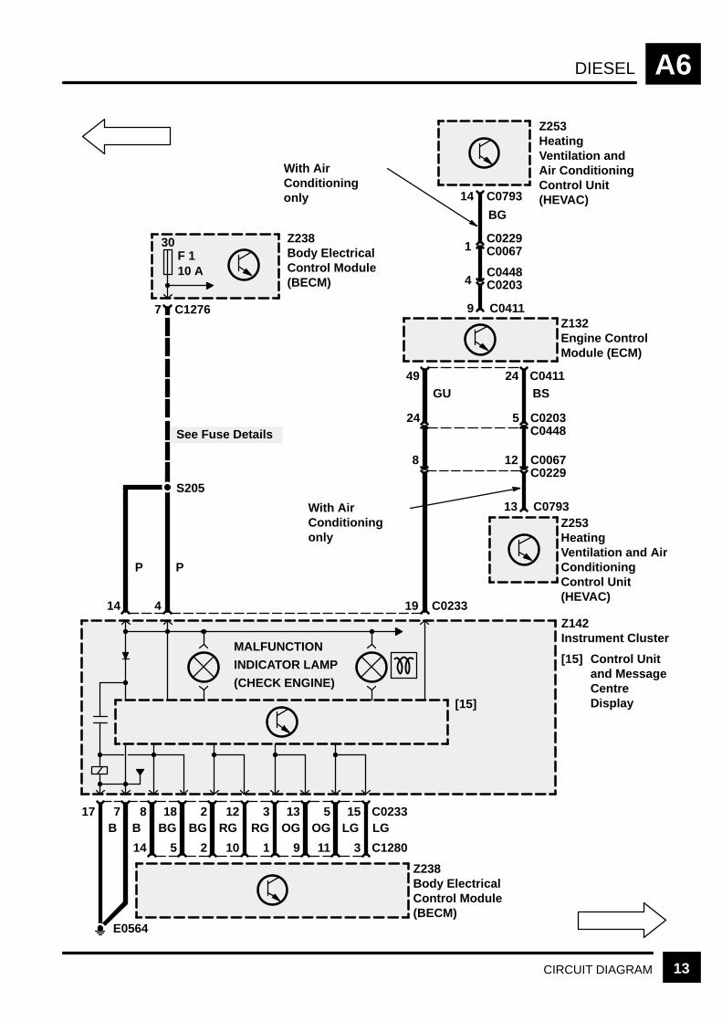
DIESEL A6
13CIRCUIT DIAGRAM
E0564
7 C023317B B
8BG
14
18BG
5
2RG
2
12RG
10
3OG
1
13OG
9
5LG
11
15LG
3 C1280
Z238Body ElectricalControl Module(BECM)
30F 110 A
Z238Body ElectricalControl Module(BECM)
S205
See Fuse Details
PP
14 4
C12767
C023319
GU
Z253HeatingVentilation and AirConditioningControl Unit(HEVAC)
C079313
BG
12 C0067C0229
C0203C0448
5
8
24
BSC04112449
Z132Engine ControlModule (ECM)
C04119
4C0448C0203
C0229C00671
MALFUNCTION
INDICATOR LAMP
(CHECK ENGINE)
C079314
Z253HeatingVentilation andAir ConditioningControl Unit(HEVAC)
With AirConditioningonly
With AirConditioningonly
Z142Instrument Cluster
[15] Control Unitand MessageCentreDisplay[15]
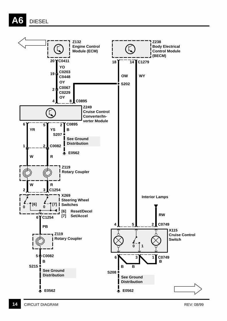
DIESELA6
14 CIRCUIT DIAGRAM REV: 08/99
E0562
S215
0[6]
0[7]
6 C1254
PB
Z119Rotary Coupler
X269Steering WheelSwitches
[6] Reset/Decel[7] Set/Accel
B
See GroundDistribution
3 C12542W R
Z119Rotary Coupler
5 C0082
W R
2 C00821
5 C08956
E0562
S207B
See GroundDistribution
YR YS
4 C08958
C041120
YO
2 C0067C0229OY
OY
19 C0203C0448
Z249Cruise ControlConverter/In-verter Module
Z132Engine ControlModule (ECM)
C127914
WY
Z238Body ElectricalControl Module(BECM)
18
OW
E0562
S208
X115Cruise ControlSwitch
B
See GroundDistribution
6 C0749
B
3
4 C0749
1
2
B
5
S202
Interior Lamps
RW
0 1
2
DIESEL A6
15CIRCUIT DIAGRAM
1 C0209
X105Mass Air FlowSensor
2 6 C02093 5
S571
E0556D
G
A6-9
6
Z132Engine ControlModule (ECM)
3834
2 C0272
F
A6-5
RW
1 C0272
K171EGR ControlSolenoid
B
RW
RY UW NG B
See GroundDistribution
S572Partial
C0411

DIESELA6
16 CIRCUIT DIAGRAM REV: 11/2000
P125aEngine CompartmentFuse Box
[2] Ignition CoilsRelay(Petrol)/CoolingFan Relay(Diesel)
UB
Shorting Link13 (Diesel)
Shorting Link8 (Diesel)
30F 2830 A
6 C0575
1 C1505
S101
RB
3 C0570
1 C1506
E0577
RL2[2]
2 C1505
X335Cooling FanSwitch
See GroundDistribution
See Fuse Details
B
2 C1506M167Cooling FanMotor
B
M
(MY 2000)
STARTING AND CHARGING B1
CIRCUIT OPERATION 1
CIRCUIT OPERATION
Starting System
When the Ignition Switch (X274) is switched toposition III, the BeCM (Z238) grounds the startersolenoid relay inside the Engine Compartment FuseBox (P125) which then energizes, applying batteryvoltage to the Starter Solenoid (K136) and Starter(M134).
Charging System
When the Ignition Switch (X274) is in position II, theBeCM (Z238) turns the charge warning light on viathe datalink connection to the Instrument Pack(Z142)
When the Generator (Z106) starts to produce power,the BeCM (Z238) gets an input signal on Pin 15 andturns off the charge warning light.
For the Diesel engine this signal is also used as aninput signal for the fuel pump relay inside the EngineCompartment Fusebox (P125) to make sure that theFuel Pump (M109) is only supplied with power whenthe engine is running.
If the Generator (Z106) fails to produce power, thecharge warning light remains illuminated.
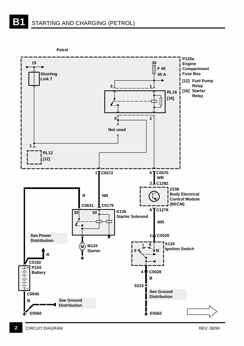
STARTING AND CHARGING (PETROL)B1
2 CIRCUIT DIAGRAM REV: 08/99
P125aEngineCompartmentFuse Box
[12] Fuel PumpRelay
[16] StarterRelay
30F 4040 A
15
RL16
[16]
Not used
RL12
[12]
3 1
25
P104Battery
See PowerDistribution
K136Starter Solenoid
See GroundDistribution
6 C0570
2 C1282WR
1 C0572
NRR
R
B
6 C1278
1 C0028
WR
4 C0028
B
0I II
III
Z238Body ElectricalControl Module(BECM)
X134Ignition Switch
S215
M
See GroundDistribution
M134Starter
ShortingLink 7
E0560 E0562
1
30 50
Petrol
C0631 C0179
C0192
C0045
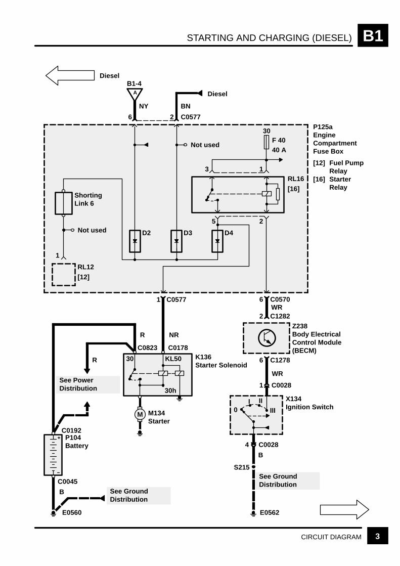
STARTING AND CHARGING (DIESEL) B1
3CIRCUIT DIAGRAM
Diesel
P125aEngineCompartmentFuse Box
[12] Fuel PumpRelay
[16] StarterRelay
30F 4040 A
RL16
[16]
RL12
[12]
3 1
25
P104Battery
See PowerDistribution
K136Starter Solenoid
See GroundDistribution
6 C0570
2 C1282WR
1 C0577
NRR
R
B
6 C1278
1 C0028
WR
4 C0028
B
0
Z238Body ElectricalControl Module(BECM)
X134Ignition Switch
S215
M
See GroundDistribution
M134Starter
E0560 E0562
1
30 KL50
D3D2
6 2
A
B1-4
Diesel
NY BN
C0577
30h
I IIIII
ShortingLink 6
Not used
Not used D4
C0823 C0178
C0192
C0045

STARTING AND CHARGINGB1
4 CIRCUIT DIAGRAM REV: 08/99
P104Battery
See PowerDistribution
R
B See GroundDistribution
E0560
K136Starter Solenoid
Z106Generator
[1] VoltageRegulator
30
D+
B+[1]
A
B1-3
15 C1289
NY
Z238Body ElectricalControl Module(BECM)
25 C0203
Z106Generator
[1] VoltageRegulator
D+
B+ [1]
R
NY
25C0162C0448
S573
NY
C0448
C0823 Diesel
C0226P
C0185C0183
C0226D
C0192
C0045
See PowerDistribution
S137
NY
Petrol
Diesel
R

STARTING AND CHARGING B1
5CIRCUIT DIAGRAM
Z142InstrumentCluster
[15] Control Unitand Mess-age CentreDisplay
30F 1
[15]
5 C1280
BG
7 C0233
Z238Body ElectricalControl Module(BECM)
14 4
P P
C0233
Z238Body ElectricalControl Module(BECM)
7 C1276
S205
17 188
14
BG
10
RG
122
2
RG
9
OG
133
1
OG
3
LG
155
11
LGB
E0564
See Fuse Details
B
10 A
STARTING AND CHARGINGB1
TROUBLESHOOTING HINTS REV: 08/996
TROUBLESHOOTING HINTS
1. If the charge warning light does not light with theengine off and the Ignition Switch (X274) in positionII, check the bulb. If ok, check BeCM (Z238),Instrument Pack (Z142) and the datalink betweenthem.
SYSTEM DIAGNOSIS
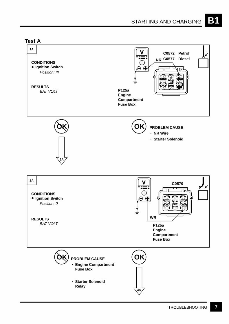
2. If the Starter Solenoid (K136) does not click andthe engine does not crank, do Test A.
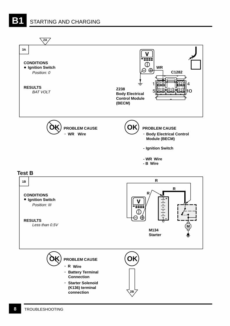
3. If the Starter Solenoid (K136) clicks but theengine does not crank or cranks slowly, do Test B.
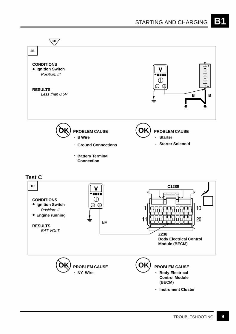
4. If the charge warning light stays lit with theengine running, and the Generator (Z106) is ok, doTest C.
STARTING AND CHARGING B1
7TROUBLESHOOTING
Starter SolenoidRelay
Engine CompartmentFuse Box
P125aEngineCompartmentFuse Box
P125aEngineCompartmentFuse Box
BAT VOLT
Test A
OK OK
OK OK
3A
1A
2A
CONDITIONSIgnition Switch
Position: III
RESULTSBAT VOLT
CONDITIONSIgnition Switch
Position: 0
RESULTS
2A
PROBLEM CAUSENR Wire-
- Starter Solenoid
PROBLEM CAUSE-
V
V
C0572C0577NR
WR
C0570
-
PetrolDiesel
STARTING AND CHARGINGB1
8 TROUBLESHOOTING
Starter Solenoid(K136) terminalconnection
Battery TerminalConnection
Less than 0.5VM134Starter
Z238Body ElectricalControl Module(BECM)
OK OKPROBLEM CAUSE
OK OK
2B
3A
1B
CONDITIONSIgnition Switch
Position: 0
RESULTSBAT VOLT
WR
CONDITIONSIgnition Switch
Position: III
RESULTS
Wire-
Test B
2A
PROBLEM CAUSEBody Electrical ControlModule (BECM)
-
PROBLEM CAUSE
R Wire-
-
C1282
V
WR
V
R
M
R
R
-
Ignition Switch-
Wire- WRWire- B
STARTING AND CHARGING B1
9TROUBLESHOOTING
Z238Body Electrical ControlModule (BECM)
BAT VOLT
OK OKPROBLEM CAUSE
OK OK
2B
1C
CONDITIONSIgnition Switch
Position: III
RESULTSLess than 0.5V
B
CONDITIONSIgnition Switch
Position: II
RESULTS
Wire-
-
Engine running
Battery TerminalConnection
Ground Connections
-
Test C
1B
PROBLEM CAUSEStarter-
- Starter Solenoid
PROBLEM CAUSENY Wire-
PROBLEM CAUSEBody ElectricalControl Module(BECM)
-
V C1289
V
B B
NY
Instrument Cluster-

CRUISE CONTROL B5
CIRCUIT OPERATION 1
CIRCUIT OPERATION
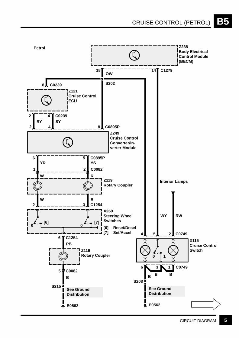
Petrol Engine
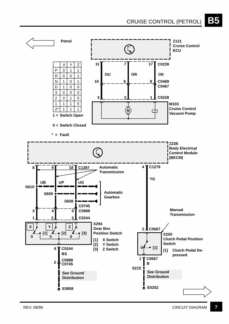
For vehicles equipped with a manual transmission,cruise control can only be activated when the CruiseControl Switch (X115) is depressed, the transfergear box is in Hi range, and the clutch pedal is notdepressed. Also, the BeCM (Z238) will deactivatecruise control if the engine rpm rises above 5000 ±10%, due to the possibility of selecting gearsmanually without the use of the clutch.
For vehicles equipped with an automatictransmission, cruise control can only be activatedwhen the Cruise Control Switch (X115) is depressed,the transfer gear box is in Hi range, and thetransmission is in one of the forward gears.
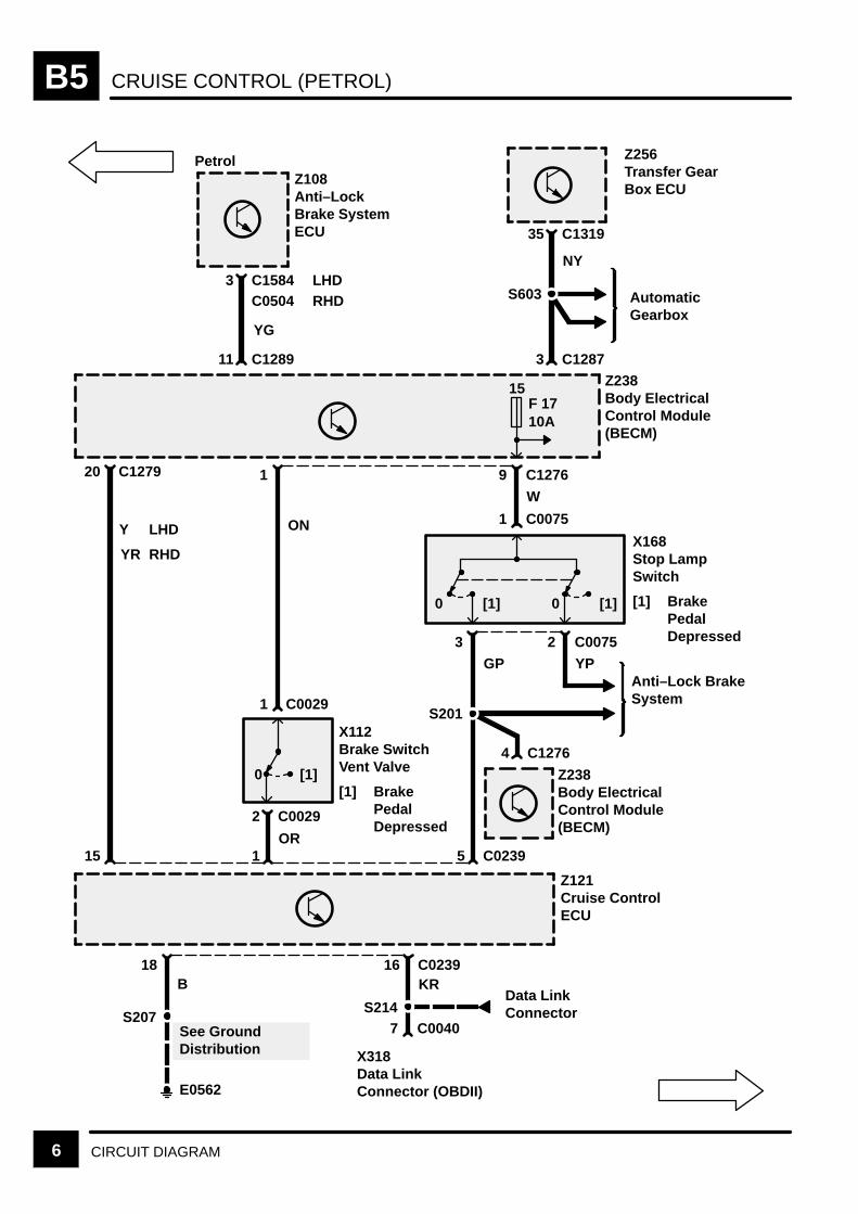
With the Cruise Control Switch (X115) on, a groundsignal is applied to C1279/Pin 14 of the BeCM(Z238).The BeCM (Z238) then suplies signal voltagevia its Pin 18 to the Converter/Inverter (Z249), to Pin8 of the Cruise Control ECU (Z121) and to the“Operation” bulb of the Cruise Control Switch (X115).The transfer gearbox Hi range status from theTransfer Gear Box ECU (Z256) is applied toC1287/Pin 3 of the BeCM (Z238). The X, Y, and Zswitch status (PRND321 position information) fromthe gearbox position switch is applied to C1287/Pins8, 9, and 18 of the BeCM (Z238). The clutch pedalposition input is applied to C1279/Pin 4 and theengine speed input C1288/Pin 9 of the BeCM(Z238). When the transfer gearbox is in Hi range, aforward gear is selected and the Cruise ControlSwitch (X115) is on, theBeCM (Z238) suplies voltagevia C1276/Pin 1 and the Brake Switch Vent Valve(X112) to the Cruise Control ECU (Z121) Pin 1,which then “knows” that cruise control can beoperated.
When cruise control is activated and a cruise speedis set, the Cruise Control ECU (Z121) appliesvoltage through the OU wire and ground through theOR wire to operate the Cruise Control VacuumPump (M103) motor. The Cruise Control ECU (Z121)applies ground through the OK wire to close thenormally open solenoid valve in the pump. The pumpapplies vacuum to the actuator.
SET/ACCEL
To set a cruise speed, the Cruise Control Switch(X115) must be on and vehicle speed must exceed28 mph (45 km/h). When the SET/ACCEL Switch isdepressed under these conditions, the
Converter/Inverter (Z249) is supplied with a groundsignal. This signal is “converted” to a voltage signaland is transmitted via the SY wire to the CruiseControl ECU (Z121) terminal 4, causing the vacuumpump to operate. When the SET/ACCEL Switch isreleased, the signal is removed from terminal 4,signalling the ECU to set the speed.
RES/DECEL
When the RES/DECEL Switch is depressed, a signalis applied via the RY wire to terminal 2 of the CruiseControl ECU (Z121). This tells the ECU (Z121) todisengage the system and the vehicle slows down.When the switch is depressed a second time, thesignal is again applied to the ECU (Z121) and thevehicle returns to the previously set speed.
Speed Input
Terminal 15 of the Cruise Control ECU (Z121)receives the Vehicle Speed output signal from theBeCM (Z238) through the Y or YR wire. The BeCM(Z238) receives the vehicle speed signal from theAnti–lock Brake System ECU (Z108). The signal is apulsing voltage and its frequency changes withvehicle speed.
CRUISE CONTROLB5
CIRCUIT OPERATION REV: 08/992
System Disable
The cruise control system can be disabled in one offour ways:
1. The Cruise Control Switch (X115) is put in the 0position, removing the BeCM (Z238) power fromthe Cruise Control ECU (Z121) and vacuumpump, and erasing the set speed memory.
2. The RES/DECEL Switch is depressed, signallingthe Cruise Control ECU (Z121) via the Inverter/Converter (Z249) to disengage the system.
3. The brake pedal is depressed and a vacuum val-ve in the Switch Vent Valve opens (X112). Thisvents vacuum to the actuator valve and releasesthe throttle.
4. The Voltage applied to the Cruise Control ECU(Z121) terminal 1 is interrupted, causing theCruise Control ECU (Z121) to turn off thevacuum pump and de–energize the vacuumsolenoid valve. This voltage path is interruptedwhen:
The brake pedal is depressed. With the brakepedal depressed, the Brake Switch Vent Valve(X112) moves to position 1 and the circuit is in-terrupted.
The transfer gear box is not in Hi range.
The vehicle speed does not exceed 28 mph (45km/h).
The vehicle is not in a forward gear (P, R, or N)(Automatic Transmission).
The clutch pedal is depressed (ManualTransmission).
The engine rpm rises above 5000 ± 10%(Manual Transmission).
The BeCM (Z238), which monitors these signals, willthen remove power from C1279/Pin 18.
Diesel Engine
For vehicles equipped with a manual transmission,cruise control can only be activated when the CruiseControl Switch (X115) is depressed and the clutchpedal is not depressed. The Diesel Engine ControlModule (Z132) will not allow the engine to overspeedif a cruise control speed is requested that is beyondthe capability of the engines speed range.
For vehicles equipped with an automatictransmission, cruise control can only be activatedwhen the Cruise Control Switch (X115) is depressed,the transfer gear box is in Hi range, and thetransmission is in one of the forward gears.
With the Cruise Control Switch (X115) on, a groundsignal is applied to C1279/Pin 14 of the BeCM(Z238). The X, Y, and Z switch status (PRND321position information) from the gearbox positionswitch is applied to C1287/Pins 8, 9, and 18 of theBeCM (Z238). The clutch pedal position input isapplied to C1279/Pin 4 and the engine speed input isapplied to C1288/Pin 9 of the BeCM (Z238). TheBeCM (Z238) then supplies voltage, via its Pin 18 tothe Inverter/Converter (Z249) and to the “Operation”bulb of the Cruise Control Switch (X115).
The Cruise Control Converter/Inverter Module(Z249) supplies the Engine Control Module (Z132)via its pin 4 with a voltage signal to “switch on” thecruise circuit. For the Diesel Engine, the EngineControl Module (Z132) controls the cruise circuit asthe Cruise Control ECU (Z121) does for the PetrolEngine. The Engine Control Module (Z132) is alsoresponsible for the acceleration/deceleration of thevehicle.
CRUISE CONTROL B5
CIRCUIT OPERATION 3
SET/ACCEL
To set a cruise speed, the Cruise Control Switch(X115) must be on and vehicle speed must exceed28 mph (45 km/h). When the SET/ACCEL Switch isdepressed under these conditions, theInverter/Converter (Z249) is suppplied with a groundsignal. This signal is transmitted via the OY wire tothe Engine Control Module (ECM) (Z132) causingthe vehicle to accelerate. When the SET/ACCELSwitch is released, the signal is removed signallingthe Engine Control Module (ECM) (Z132) to set thespeed.
RES
When the RES Switch is depressed, a signal isapplied to the ECM (Z132) and the vehicle will returnto the previously set speed.
Speed Input
The BeCM (Z238) receives the vehicle speed signalfrom the Anti–lock Brake System ECU (Z108). TheBeCM (Z238) then provides the vehicle speed signalto the Engine Control Module (ECM) (Z132). Thissignal is a pulsing voltage and its frequency changeswith the vehicle speed.
System Disable
The cruise control system can be disabled in twoways:
1. The Cruise Control Switch (X115) is put in the 0position, causing the BeCM (Z238) to removepower from the Engine Control Module (ECM)(Z132) and erasing the set speed memory.
2. The Voltage applied via the Inverter/Converter(Z249) to the Engine Control Module (ECM)(Z132) terminal 20 is interrupted, causing theEngine Control Module (ECM) (Z132) to disen-gage the system. This voltage path is interruptedwhen :
The brake pedal is depressed. The EngineControl Module (ECM) (Z132) has two StopLamp Switch (X168) inputs, each of oppositepolarity. The ECM (Z132) compares the polaritystates to determine when the brake pedal hasbeen depressed.
The vehicle speed does not exceed 28mph (45km/h).
The vehicle is not in a forward gear (P, R, or N)(Automatic Transmission).
The clutch pedal is depressed (ManualTransmission).
The BeCM (Z238), which monitors these signals, willthen remove power from C1279/Pin 18.
CRUISE CONTROLB5
CIRCUIT OPERATION4
Road Test
CAUTION: DO NOT ENGAGE CRUISE CONTROLWHEN VEHICLE IS BEING USED IN LOWTRANSFER GEARS.
WARNING: The use of cruise control is notrecommended on winding, snow covered or slipperyroads, or in heavy traffic conditions where constantspeed cannot be maintained.
1. Start the engine and depress the Cruise ControlSwitch (X115) to activate the cruise controlsystem. Accelerate to approximately 30 mph (50km/h) and press the SET/ACCEL Switch. Imme-diately release the switch and remove foot fromthe accelerator pedal. The vehicle should main-tain the speed at which the SET/ACCEL Switchwas pressed.
2. Press the SET/ACCEL Switch and hold at thatposition. The vehicle should accelerate smoothlyuntil the switch is released. The vehicle shouldnow maintain the new speed at which the SET/ACCEL Switch was released.
3. Press the RES/DECEL Switch while the vehicleis in the cruise control mode. The cruise controlshould disengage. Slow to approximately 35 mph(55km/h) and press the RES/DECEL Switch.Immediately release the switch and remove footfrom the accelerator. The vehicle shouldsmoothly accelerate to the previously set speed.Increase speed using the accelerator pedal.Releasing the pedal should return the vehicle tothe previously set speed.
4. Depressing the brake pedal should immediatelydisengage the cruise control system and returnthe vehicle to driver’s control at acceleratorpedal. Press the RES/DECEL Switch and thevehicle should accelerate to the previously setspeed without operation of the accelerator pedal.
5. Press the RES/DECEL Switch and allow thevehicle to decelerate to below 26 mph (42 km/h).Press the RES/DECEL Switch and remove footfrom the accelerator pedal. The vehicle shouldsmoothly adjust to the previously memorizedspeed.
6. Press the SET/ACCEL Switch below 28 mph(45km/h) and the cruise control system shouldremain disengaged. Accelerate the vehicleabove 28 mph (45 km/h), press the RES/DECELSwitch and remove foot from the acceleratorpedal. The vehicle should smoothly adjust to thepreviously memorized speed.
7. Pressing the Cruise Control Switch (X115)should immediately disengage the cruise control
system and erase the previously set speed fromCruise Control ECU (Z121)/Engine ControlModule (ECM) (Z132) memory.
CRUISE CONTROL (PETROL) B5
5CIRCUIT DIAGRAM
Z238Body ElectricalControl Module(BECM)
C0749
C1279
X115Cruise ControlSwitch
4 2
18 14
5
See GroundDistribution
6 C0749
BS208
E0562
3 1
B B
Z121Cruise ControlECU
8
C02392 4RY
Z249Cruise ControlConverter/In-verter Module
C0895P6 5YR
8 C0895P42
2 C00821
Z119Rotary Coupler
YS
C12542 3
X269Steering WheelSwitches
[6] Reset/Decel[7] Set/Accel
C12546
PB
Z119Rotary Coupler
See GroundDistribution
S215
E0562
W R
5 C0082
RWWY
SY
OW
C0239
W R
Interior Lamps
[6] [7]
S202
0 0
Petrol
0 1
B
CRUISE CONTROL (PETROL)B5
6 CIRCUIT DIAGRAM
C1287
Z256Transfer GearBox ECU
C131935
3
NY
S603
Z108Anti–LockBrake SystemECU
C15843
11 C1289
YG
Z238Body ElectricalControl Module(BECM)
C12761 9
ON C0075
1
1
X168Stop LampSwitch
[1] BrakePedalDepressedC00752
YP
[1] [1]
3
0 0
GP
15F 17
AutomaticGearbox
10A
Anti–Lock BrakeSystem
S201
C12764
Z121Cruise ControlECU
C02395
See GroundDistribution
18B
S207
E0562
Z238Body ElectricalControl Module(BECM)
20
Y
15
X112Brake SwitchVent Valve
[1] BrakePedalDepressed
[1]
2
0
1
C0029
OR
C1279
YR
LHD
RHD
LHDC0504 RHD
C0029
W
Petrol
KR
S214
C0239
C00407
X318Data LinkConnector (OBDII)
16
Data LinkConnector
CRUISE CONTROL (PETROL) B5
7CIRCUIT DIAGRAMREV: 08/99
Z121Cruise ControlECU
C02391711
OU
Z238Body ElectricalControl Module(BECM)
4
YG
2
See GroundDistribution
1B
S215
E0252
C0667
8
X200Clutch Pedal PositionSwitch
[1] Clutch Pedal De-pressed
[1]0
UB
AutomaticTransmission
C0667
7
OR OK
8 C0469910
C022813
M103Cruise ControlVacuum Pump
2
ManualTransmission
M
P 0 1 1R 0 0 1N 1 0 1D 1 0 03 0 0 02 0 1 0
1 1 1 0Z* 1 1 1
X Y Z
1
X294Gear BoxPosition Switch
[1] X Switch[2] Y Switch[3] Z Switch
[1]0
9
UP
2
See GroundDistribution
6BS
E0808
C0244
[2]0
5C0745
43
18 C1287
UG
3
[3]0
C0244
2 C0988
S608
S609
S610AutomaticGearbox
C0467
C0988
C0745
C1279
X Y Z
Petrol
1 = Switch Open
Switch Closed
Fault* =
0 =

CRUISE CONTROL (PETROL)B5
8 CIRCUIT DIAGRAM
20C0162
9 C1288
S
C0448
17 C0637
Petrol Diesel
Z238Body ElectricalControl Module(BECM)
Z132Engine ControlModule (ECM)
20C0203C0449
50 C0411Z132Engine ControlModule (ECM)

CRUISE CONTROL (DIESEL) B5
9CIRCUIT DIAGRAM
See GroundDistribution
S207
E0252
B
Z238Body ElectricalControl Module(BECM)
C0749
C1279
X115Cruise ControlSwitch
4 2
18 14
5
See GroundDistribution
6 C0749
B
S208
E0562
3 1
B B
Z249Cruise ControlConverter/In-verter ModuleC0895D6 5
YR
8 C0895D4
2 C00821
Z119Rotary Coupler
YS
C12542 3X269Steering WheelSwitches
[6] Reset/Decel[7] Set/Accel
C12546PB
Z119Rotary Coupler
See GroundDistribution
S215
E0562
W R
5 C0082
RW
WYOW
W R
Interior Lamps
[6] [7]
S202
0 0
Z132Engine ControlModule (ECM)
C041120YO
19 C0203
2 C0067OY
OYC0229
C0448
B
10
Diesel
2
4U
C04111 2
C1502
K196Fuel Pump Assembly
[1] Fuel QuantitySolenoid
7 C1502
[1]
RWDiesel
S576
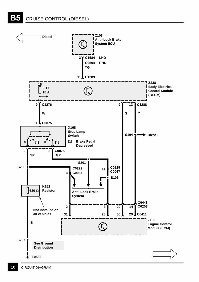
CRUISE CONTROL (DIESEL)B5
10 CIRCUIT DIAGRAM
Z108Anti–Lock BrakeSystem ECU
C15843
11 C1289
YG
Z238Body ElectricalControl Module(BECM)
C1276 139
Y
C0075
29
1X168Stop LampSwitch
[1] Brake PedalDepressed
C00752YP
[1] [1]
3
0 0
GP
15F 1710 A
Anti–Lock BrakeSystem
S203
Z132Engine ControlModule (ECM)
See GroundDistribution
B
S207
E0562
9
S
50
C1288
LHD
C0504 RHD
C0411
W
14 C020320
26
3
680
31
2
S106
14 C0229
C0448
C00679C0229C0067
S201
K152Resistor
S104 Diesel
Diesel
Not installed onall vehicles
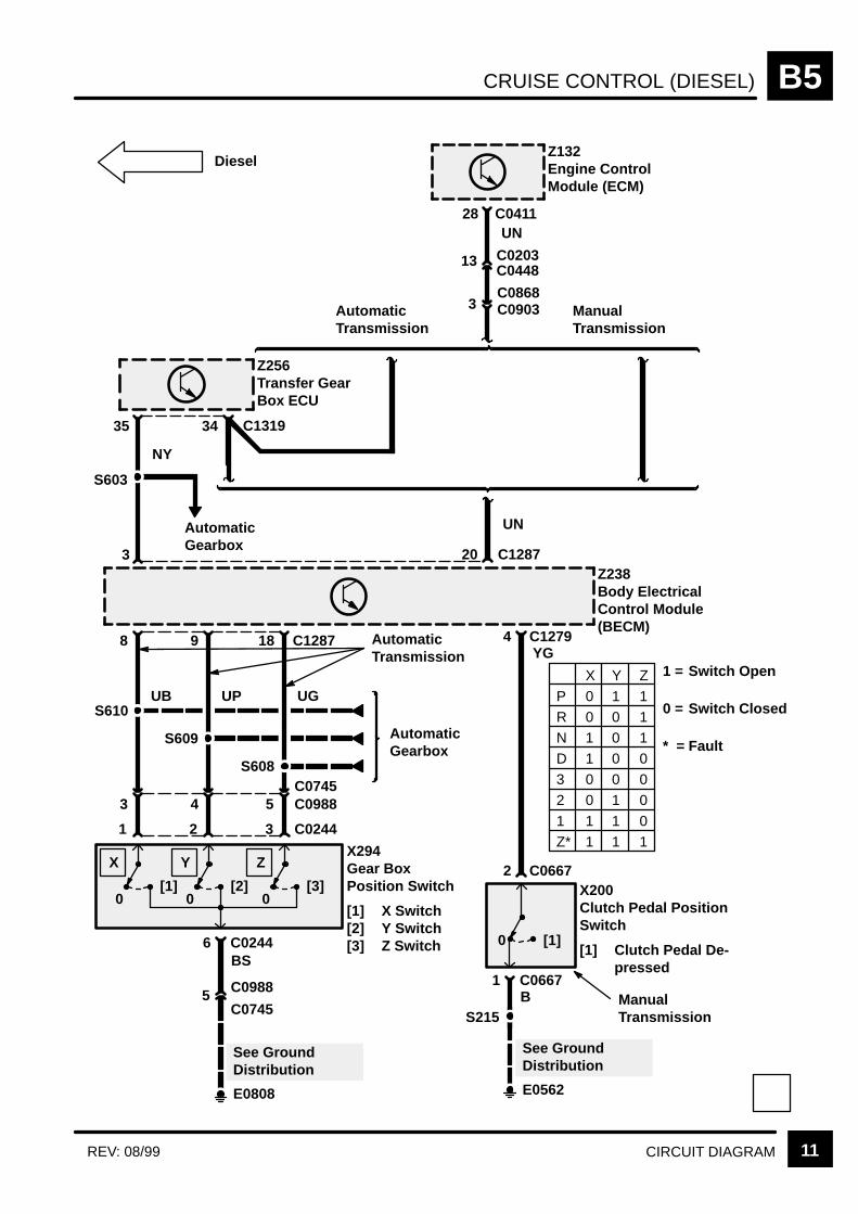
CRUISE CONTROL (DIESEL) B5
11CIRCUIT DIAGRAMREV: 08/99
Z256Transfer GearBox ECU
Z238Body ElectricalControl Module(BECM)
4YG
2
See GroundDistribution
1B
S215
E0562
C0667
8
X200Clutch Pedal PositionSwitch
[1] Clutch Pedal De-pressed
[1]0
UB
AutomaticTransmission
C0667
C12873 20
ManualTransmission
P 0 1 1R 0 0 1N 1 0 1D 1 0 03 0 0 02 0 1 0
1 1 1 0Z* 1 1 1
X Y Z
1
X294Gear BoxPosition Switch
[1] X Switch[2] Y Switch[3] Z Switch
[1]0
9
UP
2
See GroundDistribution
6BS
E0808
C0244
[2]0
5C0745
43
18 C1287
UG
3
[3]0
C0244
5 C0988
S608
S609
S610
AutomaticGearbox
C0988
C0745
C1279
X Y Z
AutomaticTransmission
Diesel
S603
AutomaticGearbox
35
NY
34
Z132Engine ControlModule (ECM)
C1319
28
3C0868C0903
13
C0411UN
C0203C0448
ManualTransmission
UN
1 = Switch Open
Switch Closed
Fault* =
0 =
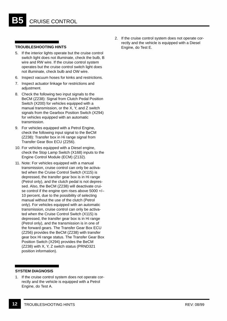
CRUISE CONTROLB5
TROUBLESHOOTING HINTS REV: 08/9912
TROUBLESHOOTING HINTS
5. If the interior lights operate but the cruise controlswitch light does not illuminate, check the bulb, Bwire and RW wire. If the cruise control systemoperates but the cruise control switch light doesnot illuminate, check bulb and OW wire.
6. Inspect vacuum hoses for kinks and restrictions.
7. Inspect actuator linkage for restrictions andadjustment.
8. Check the following two input signals to theBeCM (Z238): Signal from Clutch Pedal PositionSwitch (X200) for vehicles equipped with amanual transmission, or the X, Y, and Z switchsignals from the Gearbox Position Switch (X294)for vehicles equipped with an automatictransmission.
9. For vehicles equipped with a Petrol Engine,check the following input signal to the BeCM(Z238): Transfer box in Hi range signal fromTransfer Gear Box ECU (Z256).
10. For vehicles equipped with a Diesel engine,check the Stop Lamp Switch (X168) inputs to theEngine Control Module (ECM) (Z132).
11. Note: For vehicles equipped with a manualtransmission, cruise control can only be activa-ted when the Cruise Control Switch (X115) isdepressed, the transfer gear box is in Hi range(Petrol only), and the clutch pedal is not depres-sed. Also, the BeCM (Z238) will deactivate crui-se control if the engine rpm rises above 5000 +/–10 percent, due to the possibility of selectingmanual without the use of the clutch (Petrolonly). For vehicles equipped with an automatictransmission, cruise control can only be activa-ted when the Cruise Control Switch (X115) isdepressed, the transfer gear box is in Hi range(Petrol only), and the transmission is in one ofthe forward gears. The Transfer Gear Box ECU(Z256) provides the BeCM (Z238) with transfergear box Hi range status. The Transfer Gear BoxPosition Switch (X294) provides the BeCM(Z238) with X, Y, Z switch status (PRND321position information).
SYSTEM DIAGNOSIS
1. If the cruise control system does not operate cor-rectly and the vehicle is equipped with a PetrolEngine, do Test A.
2. If the cruise control system does not operate cor-rectly and the vehicle is equipped with a DieselEngine, do Test E.
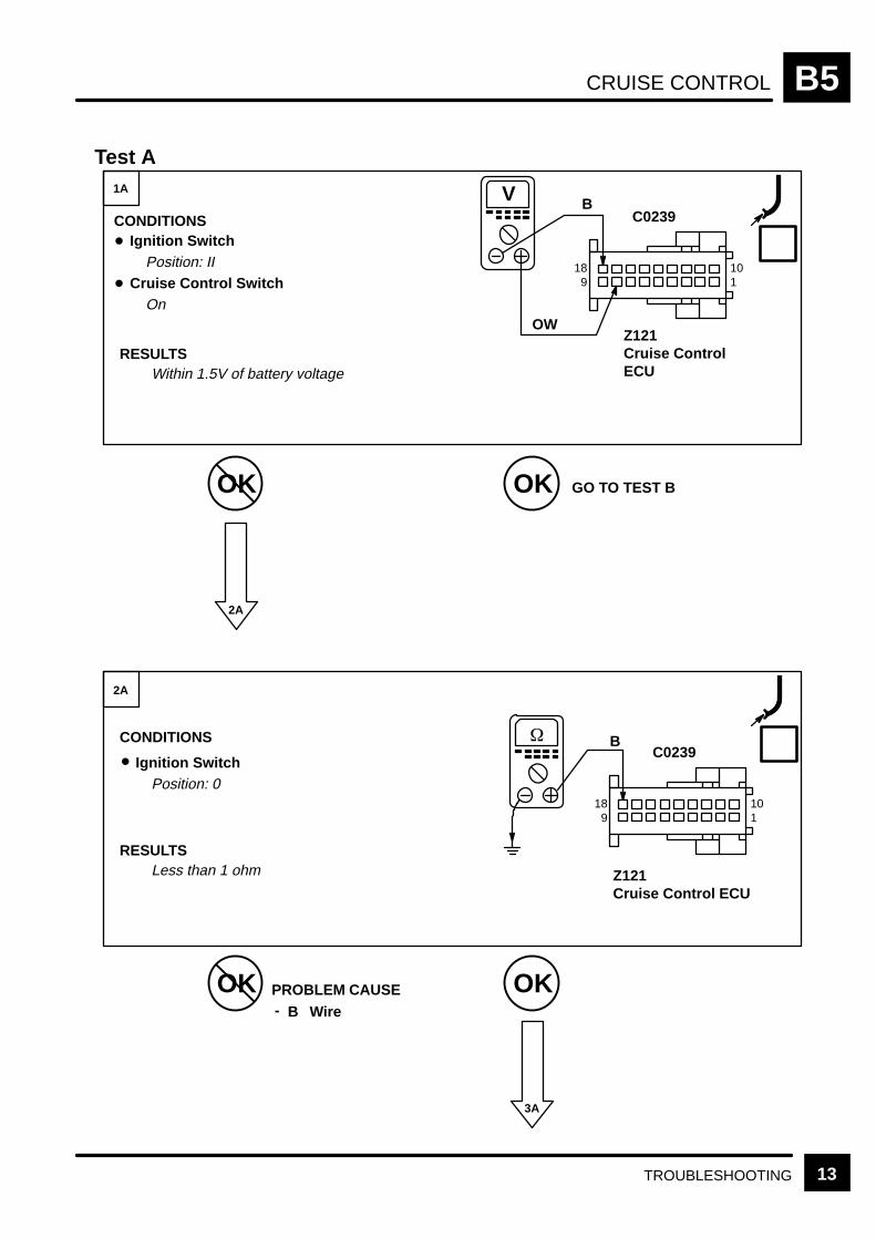
CRUISE CONTROL B5
13TROUBLESHOOTING
Test A
OK OK
OK OK
3A
1A
2A
CONDITIONSIgnition Switch
Position: II
CONDITIONS
Ignition SwitchPosition: 0
Less than 1 ohm
2A
GO TO TEST B
PROBLEM CAUSEB Wire-
Z121Cruise ControlECU
C0239
Z121Cruise Control ECU
B
Cruise Control SwitchOn
OW
RESULTS
V B
Within 1.5V of battery voltageRESULTS
101
189
C0239
101
189
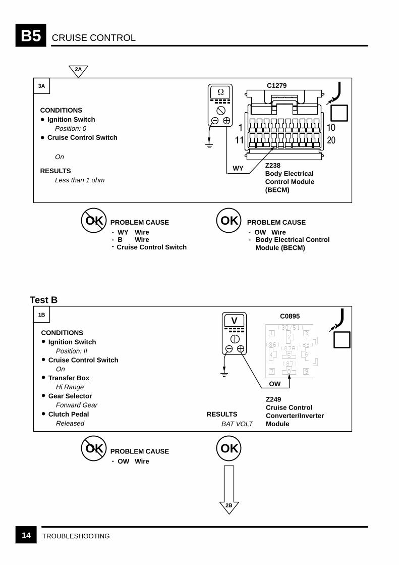
CRUISE CONTROLB5
14 TROUBLESHOOTING
RESULTS
OK OKPROBLEM CAUSE
OK OK
2B
3A
1B
CONDITIONSIgnition Switch
Position: 0
WY
CONDITIONSIgnition Switch
Position: II
Wire--
Cruise Control SwitchOn
B Wire-
Test B
2A
PROBLEM CAUSEOW Wire-
- Body Electrical ControlModule (BECM)
PROBLEM CAUSEOW Wire-
Cruise Control Switch
On
RESULTSLess than 1 ohm
Z238Body ElectricalControl Module(BECM)
C1279
WY
Z249Cruise ControlConverter/InverterModule
C0895V
OW Transfer Box
Hi Range Gear Selector
Forward Gear Clutch Pedal
Released BAT VOLT
Cruise Control Switch
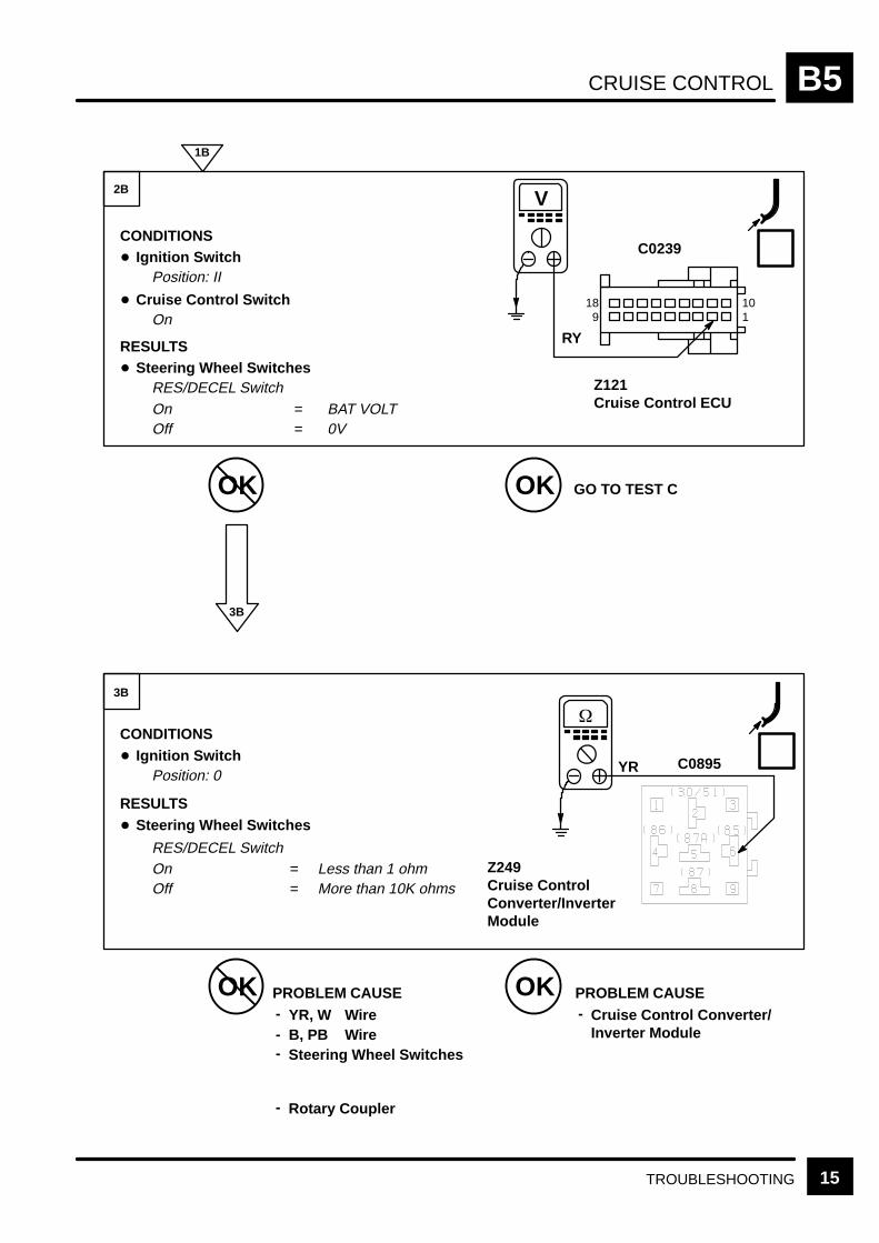
CRUISE CONTROL B5
15TROUBLESHOOTING
YR
OK OK
OK OK
2B
3B
CONDITIONSIgnition Switch
Position: II
BAT VOLT
CONDITIONSIgnition Switch
Position: 0
1B
3B
GO TO TEST C
PROBLEM CAUSEYR, W Wire-
- B, PB WireSteering Wheel Switches-
PROBLEM CAUSECruise Control Converter/Inverter Module
-
C0239
RY
OnOff
Z249Cruise ControlConverter/InverterModule
C0895
Less than 1 ohmMore than 10K ohms
==
Cruise Control SwitchOn
RESULTSSteering Wheel Switches
RES/DECEL Switch
OnOff
== 0V
RESULTSSteering Wheel Switches
RES/DECEL Switch
Rotary Coupler-
V
Z121Cruise Control ECU
101
189
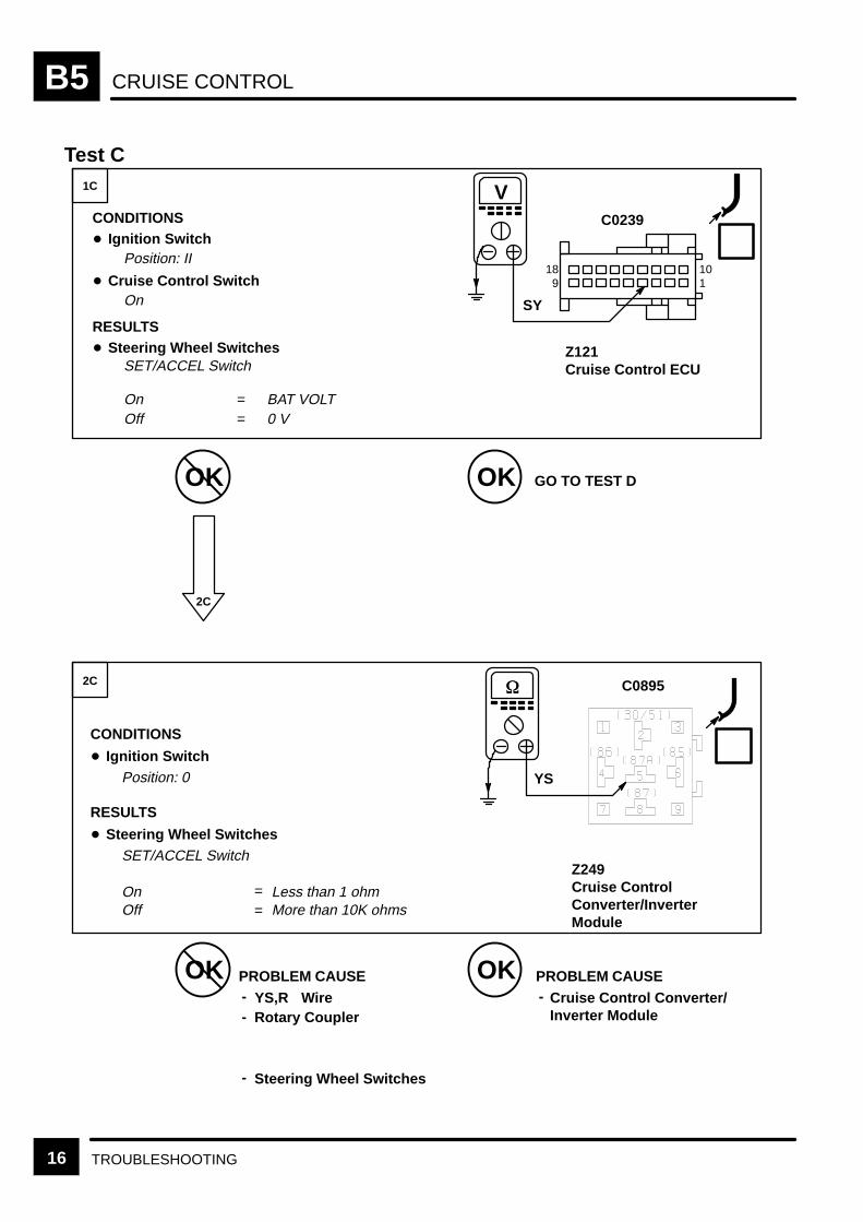
CRUISE CONTROLB5
16 TROUBLESHOOTING
On
Test C
OK OK
OK OK
1C
2C
2C
GO TO TEST D
PROBLEM CAUSEYS,R Wire-
- Rotary Coupler
Steering Wheel Switches-
PROBLEM CAUSECruise Control Converter/Inverter Module
-
Less than 1 ohm
Z249Cruise ControlConverter/InverterModule
CONDITIONS
Ignition SwitchPosition: 0
RESULTS
Steering Wheel SwitchesSET/ACCEL Switch
Off More than 10K ohms
C0895
YS
==
CONDITIONSIgnition Switch
Position: II
BAT VOLT
C0239
SY
Cruise Control SwitchOn
RESULTSSteering Wheel Switches
SET/ACCEL Switch
OnOff
== 0 V
V
Z121Cruise Control ECU
101
189
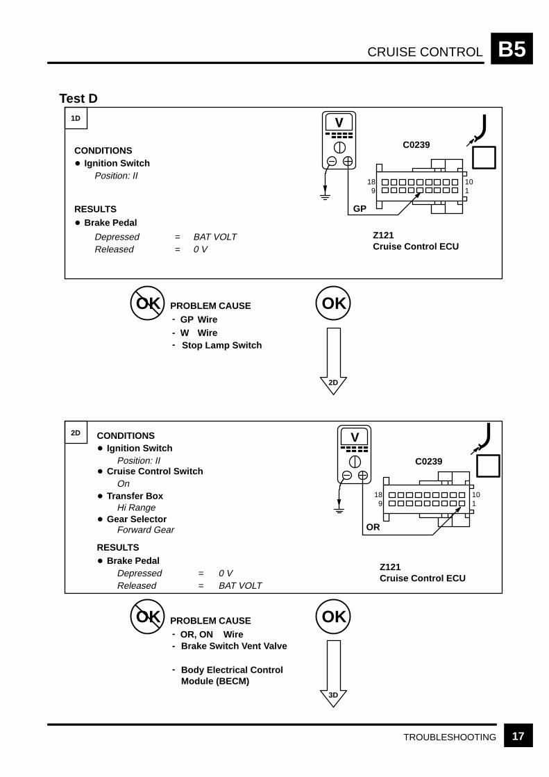
CRUISE CONTROL B5
17TROUBLESHOOTING
Test D
OK OKPROBLEM CAUSE
OK OK
3D
1D
2D
GP Wire-
-
2D
W WireStop Lamp Switch-
PROBLEM CAUSEOR, ON Wire-
- Brake Switch Vent Valve
Body Electrical ControlModule (BECM)
-
Released
Z121Cruise Control ECU
CONDITIONSIgnition Switch
Position: II
RESULTS
Brake Pedal
Depressed
BAT VOLT0 V
C0239
==
CONDITIONSIgnition Switch
Position: II
BAT VOLT
C0239
OR
Cruise Control SwitchOn
RESULTSBrake Pedal
DepressedReleased
==
0 V
V
Z121Cruise Control ECU
Transfer BoxHi Range
Gear SelectorForward Gear
GP
101
189
101
189

CRUISE CONTROLB5
18 TROUBLESHOOTING
OU
OK OKPROBLEM CAUSE
OK OK
3D
4D
CONDITIONS
Ignition SwitchPosition: II
Y, YR
CONDITIONSIgnition Switch
Position: II
Wire-
-
4D
Cruise Control Switch
On
Body Electrical ControlModule (BECM)
2D
PROBLEM CAUSEOU, OR-
- Cruise Control VacuumPump
Turn a drive wheel by hand
RESULTS
=
C0239YR
V
Z121Cruise Control ECU
Y LHDRHD
5V with ignition position II
RESULTSCruise Control Vacuum Pump
Operates
C0239
Z121Cruise Control ECU
OR
OR
Wire
5D
Transfer GearboxHi Range
Gear SelectorForward Gear
Brake PedalReleased
= 2.5V approx. with wheels turning
101
189
101
189

CRUISE CONTROL B5
19TROUBLESHOOTING
BAT VOLT
OK OKPROBLEM CAUSE
OK OK
5D
1E
CONDITIONS
Ignition SwitchPosition: II
OK
CONDITIONSIgnition Switch
Position: II
Wire-
-
Cruise Control SwitchOn
Cruise Control VacuumPump
Test E
4D
PROBLEM CAUSECruise Control ECU-
GO TO TEST F
C0239
Z121Cruise ControlECU
Gear SelectorForward Gear
Clutch PedalReleased
Cruise Control Switch
On
RESULTSCruise Control Vacuum Pump
Operates
Throttle Opens WideValve Closes
OK
OR
Z249Cruise ControlConverter/InverterModule
V C0895
B
OW
RESULTS
2E
Transfer GearboxHi Range
Gear SelectorForward Gear
Brake PedalReleased
OU
OR
101
189

CRUISE CONTROLB5
20 TROUBLESHOOTING
OK OKPROBLEM CAUSE
OK OK
2E
3E
CONDITIONSIgnition Switch
Position: 0
B
CONDITIONSIgnition Switch
Position: 0
Wire-
3E
Cruise Control Switch
On
1E
PROBLEM CAUSEWY Wire-
- B Wire
Cruise Control Switch-
PROBLEM CAUSEOW Wire-
- Body Electrical ControlModule (BECM)
RESULTSLess than 1 ohm
RESULTSLess than 1 ohm
Z249Cruise ControlConverter/InverterModule
C0895
B
Z238Body ElectricalControl Module(BECM)
C1279
WY
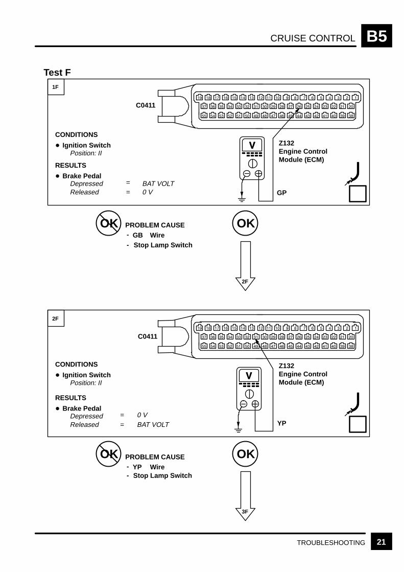
CRUISE CONTROL B5
21TROUBLESHOOTING
Test F
OK OKPROBLEM CAUSE
OK OK
3F
1F
2F
CONDITIONS
Ignition SwitchPosition: II
BAT VOLT
GB Wire-
-
2F
Stop Lamp Switch
PROBLEM CAUSEYP Wire-
- Stop Lamp Switch
RESULTS
Brake Pedal
DepressedReleased =
=0 V
CONDITIONS
Ignition SwitchPosition: II
BAT VOLT
RESULTS
Brake Pedal
DepressedReleased =
= 0 V
Z132Engine ControlModule (ECM)
V
GP
Z132Engine ControlModule (ECM)
V
YP
C0411
C0411
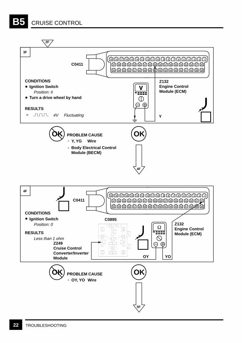
CRUISE CONTROLB5
22 TROUBLESHOOTING
OK OKPROBLEM CAUSE
OK OK
5F
3F
4F
CONDITIONSIgnition Switch
Position: II
Y, YG
CONDITIONSIgnition Switch
Position: 0
RESULTS
Wire-
-
4F
Body Electrical ControlModule (BECM)
2F
PROBLEM CAUSEOY, YO Wire-
Turn a drive wheel by hand
RESULTS
Z132Engine ControlModule (ECM)
V
Y
C0411
Less than 1 ohm
Z132Engine ControlModule (ECM)
YO
C0411
C0895
Z249Cruise ControlConverter/InverterModule OY
= 4V Fluctuating

CRUISE CONTROL B5
23TROUBLESHOOTING
OK OKPROBLEM CAUSE
OK OK
5F
6F
CONDITIONSIgnition Switch
Position: 0
YR, W Wire--
6F
B, PB WireRotary Coupler-
4F
PROBLEM CAUSEYS, R Wire-
- Rotary Coupler
Steering Wheel Switches-
PROBLEM CAUSECruise Control Converter/Inverter Module
-
RESULTSSteering Wheel Switches
OnOff
Less than 1 ohmMore than 10K ohms
==
RES/DECEL SwitchZ249Cruise ControlConverter/InverterModule
C0895
YR
Steering Wheel Switches-
CONDITIONSIgnition Switch
Position: 0
RESULTSSteering Wheel Switches
OnOff
Less than 1 ohmMore than 10K ohms
==
SET/ACCEL Switch Z249Cruise ControlConverter/InverterModule
C0895
YS
Body Electrical ControlModule (BECM)
-

TRANSFER GEARBOX B6
CIRCUIT OPERATION 1
CIRCUIT OPERATION
Interface to transfer motor inside Transfer Box(X313)
The Transmission Gearbox Control Unit (Z256) hasa seven wire interface to the Transfer Motor insidethe Transfer Box (X313), consisting of the four motorposition switches, the ground for the switches andthe drives to move the motor one way or the other.
Motor Position Switches– pins 17, 32, 33, 7
The Transmission Gearbox Control Unit (Z256)reads the position of the motor in the form of abinary Gray Code.
So the Transmission Gearbox Control Unit (Z256)can find out in which gear the Transfer Box (X313) isin and where the motor should move to, to engagethe desired range. If the Transfer Box (X313) movesoutside the normal modes (e.g. Left of High) then theTransmission Gearbox Control Unit (Z256) can movethe motor back to the correct position.
Motor Position Switch ground– pin 19
The switches on the transfer box motor arereferenced to pin 19, i.e. if there is a problem withthe harness to pin 19 then the TransmissionGearbox Control Unit (Z256) will not be able toassess where the transfer motor is and so will notmove the motor.
Motor drive Clockwise (pins 25, 26) and CounterClockwise (pins 1, 2)
The Transmission Gearbox Control Unit (Z256)receives signals from the motor position switches,the drivers request, the vehicle speed and thetransmission neutral signal and, when theparameters are correct, powers the motor from onemode to another via the motor drives. This is actuallya single wire interface for each direction which issplit down to two wires at the Transmission GearboxControl Unit (Z256) to help pass the current thoughtwo pins rather than one. If there is a problem witheither the motor drives or the harness, then themotor will not move and a range change will not bepossible.
Vehicle Speed Sensor– pins 13, 30
The Transmission Gearbox Control Unit (Z256)senses how fast the vehicle is travelling, comparesthis speed to the value stored in the memory anddecides if a range change is allowed. Presently theshift speeds are set at 5 mph High to Low and Lowto High on vehicles with an automatic transmission
and 15 mph Low to High on vehicles with a manualtransmission.
Interface to BeCM (Z238)
High, Low and Neutral Status Lamps–pins 35, 14, 36
The Transmission Gearbox Control Unit (Z256)informs the BeCM (Z238), which informs theInstrument Pack (Z142), about the range the vehicleis in via three status lamps.
When a range change is requested, the desiredrange will flash up on the display (i.e. “HIGH”) andcontinue flashing until the range change is achieved.When complete, the range message will switch toconstant and be displayed for a few seconds.
If a range change is requested and not all of theconditions are satisfied then the desired rangemessage will flash and continue flashing until all ofthe parameters are satisfied or the request isremoved.
If the transfer box neutral is selected then, after afive second safety delay, the Transfer Box (X313)moves to neutral and the display shows “NEUTRAL”.
The High and Low status lamp signals also passinformation to the H–Gate and the Auto Gear BoxControl Unit (Z255).
Interface to Engine Control Module (ECM) (Z132)
On North American Specification (NAS) vehicles, theinability of the Transfer Gear Box ECU (Z256) tomove into the High range is flagged over the faultoutput line. A fault will also be flagged in the event ofa speed sensor failure or incorrect transfer motorposition information. The Malfunction Indicator Lamp(MIL) will illuminate if a fault is recorded on twosuccessive journeys.

TRANSFER GEARBOXB6
CIRCUIT OPERATION2
Neutral Switch (X293) or Clutch Switch– pin 34
A shift between ranges is possible when thetransmission is in neutral. The TransmissionGearbox Control Unit (Z256) senses this via aPark/Neutral Switch (X293) on automatictransmission vehicles and via either a clutch switchor a lever neutral switch on manual transmissionvehicles. This signal is passed via the BeCM (Z238).
Interface to “H–Gate”– pin 35, 15 (automatictransmission only)
The H–Gate gets the range information via a Highand Low status signal from the output of theTransmission Gearbox Control Unit (Z256);e.g. when the vehicle is in High then the High side ofthe “H” is illuminated. When a range change to Lowis requested, the Low side of the “H” starts to flashwhilst the High side stays constant. When Low rangeis obtained then the flashing light on the Low sidechanges to constant and the High side light goes off.
If a range change is requested and not all of theconditions are satisfied, then the current range willstay illuminated and the desired range will flash andcontinue flashing until all of the parameters aresatisfied or the request is removed.
If the gear lever is placed in the neutral position forthe gearbox and the transfer box then, after a fivesecond safety delay, the transfer box moves toneutral and the lights on both side of the “H” areextinguished.
Interface to Auto Gear Box Control Unit (Z255)– pin 35
The High/Low signal to the Auto Gear Box ControlUnit (Z255) comes from the High range status lamp.If the Auto Gear Box Control Unit (Z255) does notreceive the range information, then an incorrect gearchange mode could be selected, i.e. Manual ratherthan Sport in High range and vice versa in Lowrange. Also, the shift strategy is different betweenthe Economy modes of High and Low and so poorshift quality could result.
Automatic Selector Park Interlock
When the gear selector lever is in the park position,the shift interlock solenoid is deenergized andprevents the selector from being moved to anothergear. To free the selector, the Ignition Switch (X134)must be in position II and the brake pedal must bedepressed.
Current is then supplied to the solenoid through thePR wire via fuse 13. The solenoid is grounded usingthe B wire to the console ground E0808.
The solenoid is now energised, freeing the selector.The solenoid is energised continuously whilst theselector lever is in any position other than park andthe Ignition Switch (X134) is in position II.

TRANSFER GEARBOX B6
3CIRCUIT DIAGRAM
Z238Body ElectricalControl Module(BECM)
C1293
13
4
W
2
23
15
GR
14
NR
30F 430 A
See GroundDistribution
AutomaticGearbox
S604
X190Vehicle SpeedSensor
E0808
30
U
1
C1319
C0195
P
9 C09898
3
C0746S603
Z256Transfer GearBox ECU
7
C12811
21
15F 710 A
W
24
P
C13194
AutomaticTransmission
ManualTransmission
4 C1290
36
4
35
NY
NW
5
C1287
10
29
S601
WU
Z268Vehicle SpeedSensor Shield
Z238Body ElectricalControl Module(BECM)
BB
B
Fuse F11 is onlyinstalled whentowing the vehicle
SCR
F 11*30 A
*
5 C0903 See Fuse Details
S607
S611
C0868
C1356
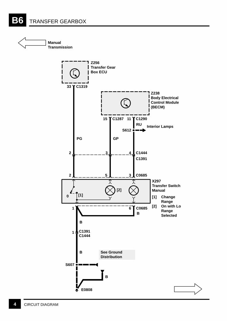
TRANSFER GEARBOXB6
4 CIRCUIT DIAGRAM
C1287
X297Transfer SwitchManual
[1] ChangeRange
[2] On with LoRangeSelected
1 C0685
B
6B
Z256Transfer GearBox ECU
S607
See GroundDistribution
E0808
C131933
2
B
11 C1290
Z238Body ElectricalControl Module(BECM)
3 C0685
RU
15
5
GP
[2][1]0
S612Interior Lamps
PG
2 C14443 4
C1391
C14441 C1391
B
ManualTransmission
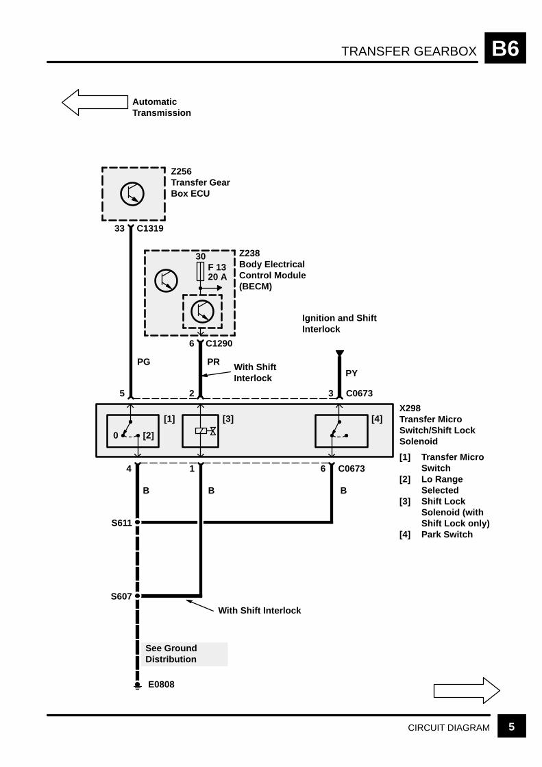
TRANSFER GEARBOX B6
5CIRCUIT DIAGRAM
AutomaticTransmission
X298Transfer MicroSwitch/Shift LockSolenoid
[1] Transfer MicroSwitch
[2] Lo RangeSelected
[3] Shift LockSolenoid (withShift Lock only)
[4] Park Switch
Z256Transfer GearBox ECU
6 C1290
Z238Body ElectricalControl Module(BECM)
C131933
5 2 C0673
PR With ShiftInterlock
4
0 [2]
[1] [3]
1 C0673
E0808
S607
S611
With Shift Interlock
PG
BB
See GroundDistribution
30F 1320 A
3
6
[4]
B
Ignition and ShiftInterlock
PY
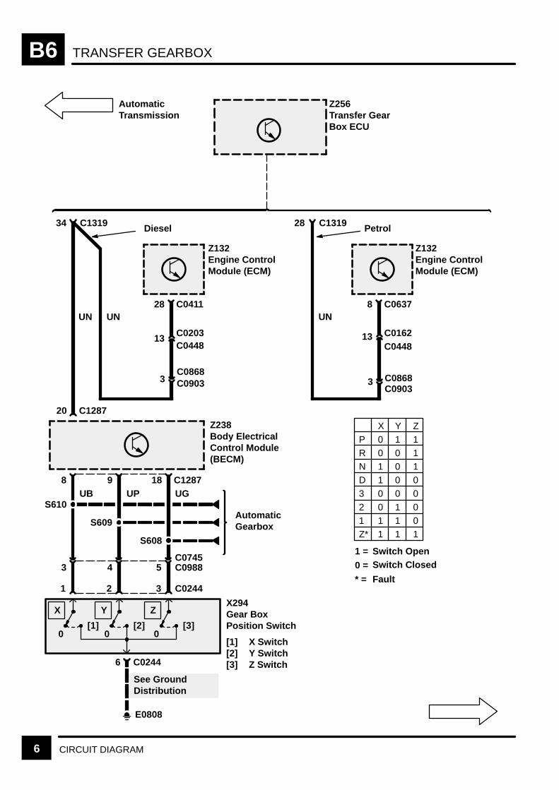
TRANSFER GEARBOXB6
6 CIRCUIT DIAGRAM
Diesel
20
AutomaticTransmission
28 C0411UNUN
C044813
34 C1319
C08683 C0903
8UB
1
X294Gear BoxPosition Switch
[1] X Switch[2] Y Switch[3] Z Switch
[1]0
9UP
2
See GroundDistribution
6
E0808
C0244
[2]0
5C0745
43
18 C1287UG
3
[3]0
C0244
S608
S609
S610AutomaticGearbox
C0988
X Y Z
C1287
Z256Transfer GearBox ECU
Z132Engine ControlModule (ECM)
Z238Body ElectricalControl Module(BECM)
Petrol
8 C0637UN
C016213C0448
28 C1319
C08683C0903
Z132Engine ControlModule (ECM)
P 0 1 1R 0 0 1N 1 0 1D 1 0 03 0 0 0
2 0 1 01 1 1 0Z* 1 1 1
X Y Z
1 =
0 =
* =
Switch OpenSwitch Closed
Fault
C0203

TRANSFER GEARBOX B6
7CIRCUIT DIAGRAM
18 C1287
1
N
2
0 1
34 C1319
E1355
S551
N
B
See GroundDistribution
C074614C0989
C0684
C0684
Z238Body ElectricalControl Module(BECM)
X293Neutral Switch
Z256Transfer GearBox ECU
ManualTransmission
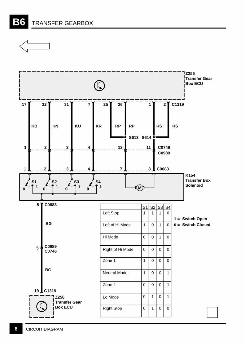
TRANSFER GEARBOXB6
8 CIRCUIT DIAGRAM
5
Z256Transfer GearBox ECU
17
KB
1
K154Transfer BoxSolenoid10
32
KN
2
10
421
7
KR
4
10
S1 S2 S4
31
KU
3
10
S3
3
C0683
25
RP
26
RP
7
11 C074612
1 C1319
RS
8 C0683
C0989
2
1 1 1 0
1 0 01
0 0 1 0
0 0 0 0
1 0 0 0
1 0 0 1
0 0 10
0 1 0 1
S2 S3 S4
19 C1319
Z256Transfer GearBox ECU
BG
C09895C0746
BG
M
S1Left Stop
Left of Hi Mode
Neutral Mode
Zone 1
Right of Hi Mode
Hi Mode
Right Stop
Lo Mode
Zone 2
RS
0 1 0 0
1 =
0 =
Switch OpenSwitch Closed
S614S613
AUTOMATIC GEARBOX B7
CIRCUIT OPERATION 1REV: 11/2000
CIRCUIT OPERATION
Economy, Sport and Manual Modes
The Auto Gearbox Control Unit (Z255) has various differentdriving modes available, with Economy being selectedautomatically on start up. When the vehicle is in Highrange, Sport mode can be selected. This will make gearchanges more sensitive to throttle movement, therebyshifting down earlier and holding lower gears longer thanthe Economy mode. If the vehicle is in Low range, Manualmode can be selected. This will make the gearbox changeinto the selected gear as quickly as possible and hold on tothat gear at all speeds.
Interface to Petrol Engine Control Module (ECM)(Z132)
The Auto Gearbox Control Unit (Z255) uses engine torque,engine speed and throttle angle signals from the ECM(Z132) to calculate which gear is required. The Auto BoxControl Unit supplies gear selection information to thesolenoid valves which will then engage the correct gear. A torque reduction signal is sent from the Auto GearboxControl Unit to the ECM which will retard the ignition pointon each cylinder. This reduces engine power during gearchanges. The combination of retarded ignition and reducedengine power delivers a smoother gear change.
Information about engine speed, engine torque, throttleangle and torque reduction is received from the ECM(Z132) by the Auto Gear Box Control Unit (Z255) via CANbus ‘high’ and ‘low’ line on pins 16 and 44.
Interface to Diesel Engine Control Module (ECM)(Z132)
The engine speed is received by the Auto Gearbox ControlUnit (Z255) via pin 3 and sent from the BeCM (Z238) viapin 11. The throttle angle signal is received by the Auto GearboxControl Unit (Z255) via pin 47 and sent from the ECM(Z132) via pin 40. The torque reduction signal is receivedby the ECM (Z132) via pin 43 and sent from the AutoGearbox Control Unit (Z255) via pin 32.
Interface to Auto Gear Box Control Unit (Z255) Gear Box Position Switch – pins 14, 33, 50, Diesel (pins 8, 36, 37 Petrol)
The Gearbox Position Switch (X294) is mounted on theside of the gearbox and contains 3 internal switches. Theswitches are connected to the Auto Gearbox Control Unit(Z255) via pins 50, 14 and 33 for diesel (pins 8, 36, 37 forpetrol). By analysing the status of these 3 switches, theAuto Gearbox Control Unit (Z255) calculates which gearthe vehicle is in.
If a fault occurs with the switch, the Auto Gearbox ControlUnit (Z255) may try to override driver requests and select adifferent gear.
Solenoid Valves – pins 5, 6, 19, 24, 42 Diesel (pins 5, 30, 32, 33, 53 Petrol)
The Auto Gearbox Control Unit (Z255) has control over 4solenoid valves: MV1, MV2, torque converter lock up andpressure regulator. These are all supplied via pin 19 diesel(pin 53 petrol), which is activated via a relay in the AutoGearbox Control Unit (Z255) itself.
MV1 – pin 5 Diesel (pin 30 Petrol), MV2 – pin 24 Diesel (pin 33 Petrol)
When the driver selects ”D” (drive), the Auto GearboxControl Unit (Z255) controls gear selection via two solenoidvalves. If a fault occurs with one or both of the valves, adifferent gear than the one selected will result.
If the Auto Gear Box Control Unit (Z255) detects this faultthe Limp home Function is activated to prevent damagebut to maintain driveability. The common supply to all thesolenoid valves is removed and the pressure regulator isset mechanically to maximum pressure. The effect on thetransmission will depend on what position MV2 was inbefore the Limp home Function became active. Thegearbox will mechanically shift to either third or fourth gearuntil the ignition is switched OFF.
MV2 is also used to prevent the driver from selectingreverse gear when the vehicle is moving forward at speedsgreater than 8 km/h and from disengaging reverse gear atspeeds greater than 6 km/h. This function is known as ”Reverse Safety” and will not beavailable if MV2 is non–operational and/or the gearbox is indefault mode.
Torque Converter Lock–Up Solenoid – pin 42 Diesel (pin 32 Petrol)
The torque converter slips to allow smooth operation of thegearbox. Lock–Up occurs when the vehicle reaches aspeed of 45 mph or above in either third or fourth gears.
Pressure Regulator Solenoid – pin 6 Diesel (pin 5 Petrol)
Gearshift quality is controlled by modulating the pressureregulator which is controlled by the Auto Gearbox ControlUnit (Z255). When energised the solenoid is in the closedposition. If a failure occurs, the common supply to all thesolenoids is removed and the pressure regulator is setmechanically to maximum pressure.
Output Shaft Speed Sensor – pins 2, 38, 20 Die-sel (pins 42, 14, 15 Petrol)
The automatic gearbox system incorporates an outputshaft speed sensor which provides an input to the AutoGearbox Control Unit (Z255) on pin 2 diesel (pin 42 petrol)and pin 38 diesel (pin14 petrol) with a screen over thecable attached to pin 20 diesel (pin 15 petrol). It isimportant that this signal is screened correctly because it isa low amplitude analogue signal that can be affected byexternal interference.
AUTOMATIC GEARBOXB7
CIRCUIT OPERATION2 REV: 11/2000
MES 1 and 2 – pins 16, 31 Diesel (pins 25, 51 Pet-rol)
The two Manual/Economy/Sport (MES) lines indicate to theBeCM (Z238) which mode has been selected or if a faultwithin the transmission has occurred.
Interface to Transmission Gearbox Control Unit(Z256) High/Low Range Signal – pin 46 Diesel (pin 13Petrol)
The High/Low signal is used by the Auto Gearbox ControlUnit (Z255) to select the correct mode on application of the”MES” switch. Also, the gear shift points and strategies arevery different in the different ranges.
Interface to H–Gate – pin 29 Diesel (pin 45 Pet-rol)
The H–Gate sensor module (Z254) displays selected gearinformation from the Gearbox Position Switch (X294), ratioinformation from the Transmission Gearbox Control Unit(Z256) and mode information from Auto Gearbox ControlUnit (Z255). The H–Gate receives a signal from the ignitionswitch when it is turned to position II on a W wire. This issupplied via fuse 6 and is grounded to the console groundE0808 via a B wire.
Information on the selected gear is received from theGearbox Position Switch (X294) on UB, UP and UG wires.These three lines also provide a feed to the Auto GearboxControl Unit (Z255) and the BeCM (Z238).
Information on the gearbox mode (sport or manual) isreceived on a YG wire and a YR wire. These two lines alsogo to the BeCM (Z238).
The High–Ratio gear range position signal is received bythe Auto Gearbox Control Unit (Z255), TransmissionGearbox Control Unit (Z256) and the BeCM (Z238). Thissignal is sent from the H–gate Sensor Module (Z254) on aNY wire via pin 8.
The Low–Ratio gear range position signal is received bythe Transmission Gearbox Control Unit (Z256) and theBeCM (Z238). This signal is sent from the H–gate SensorModule (Z254) on a NR wire via pin 11.
If the Auto Gearbox Control Unit (Z255) does not receive aHigh–Ratio gear range position signal it will assume thatLow–Ratio gear range has been selected.
The illumination signal is on a RU wire.
The mode request is on the UO wire. This is sent from theH–gate Sensor Module (Z254) via pin 10 to the AutoGearbox Control Unit (Z255) via pin 29 diesel (pin 45petrol). Pressing the momentary action mode button whilein High–Ratio gear range will activate or deactivate SportMode. Pressing the momentary action mode button whilein Low–Ratio gear range will activate or deactivate ManualMode. Changing from High–Range to Low–Range or fromLow–Range to High–Range will automatically cancel SportMode or Manual Mode.
Gearbox Oil Cooler – Diesel
The gearbox cooling process relies mainly on ram airentering through an aperture in the LH side of the bumpermoulding and is dispersed over the oil cooler. The cooledoil is fed back to the automatic gearbox via the return pipe,which is located parallel to the feed pipe on the LH side onthe automatic gearbox.
A small electric fan is fitted to the front of the oil cooler tocool the gearbox oil during long periods of elevatedgearbox oil temperatures i.e. during extended idle in driveor low speed towing. A gearbox oil temperature switch isfitted adjacent to the warning light switch on the oil cooler.This switch monitors the gearbox oil temperature. Whenthe gearbox oil temperature reaches 95C ± 3C theswitch provides the ground for the oil cooler relay located inthe engine compartment fusebox.
The relay receives a power supply on pin 86 from shortinglink 8 (J792) in the engine compartment fusebox. Theground for the relay pin 85 is provided through the gearboxoil temperature switch. The relay therefore will not energiseunless the gearbox oil temperature switch reaches itsdefined limit of 95C ± 3C.
A separate power supply is connected to the relay pin 30from fuse F28 (30A). When the gearbox oil temperatureswitch energises the relay, power is routed via relay pin 87to the electric fan located on the front of the oil cooler.
As gearbox oil temperature decreases the oil temperatureswitch deactivates the relay by breaking the relay coilground circuit. As the ground circuit for the relay isinterrupted, the power supply is disconnected.
The ground for both the gearbox oil temperature switchand the electric fan is via a ground point (E0557).

AUTOMATIC GEARBOX B7
3CIRCUIT DIAGRAMREV: 08/99
Z238Body ElectricalControl Module(BECM)
KR
12 C1287
31
30F 35 A
7
PY
26
15F 710 A
1 C1281
W
54
See Fuse Details
Z132Engine ControlModule (ECM)
36 C0637
YB YN
21C0448
22
S607
6 28 C1320
See GroundDistribution
E0808
Z255Auto Gear BoxControl Unit
B
C0162
37
16 44
1 2 C0903C0868
C1290
5 C0903C0868
C1320
Petrol
B
SequentialMultiport FuelInjection (SFI–V8)
W
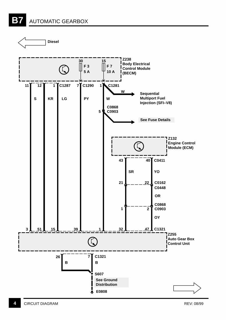
AUTOMATIC GEARBOXB7
4 CIRCUIT DIAGRAM REV: 08/99
LG
Z238Body ElectricalControl Module(BECM)
11
S
3
12
KR
51
1 C1287
15
30F 35 A
7
PY
39
15F 710 A
C1281
W
1
S607
7 C1321
See GroundDistribution
E0808
Z255Auto Gear BoxControl Unit
B
Z132Engine ControlModule (ECM)
43
SR YO
22C0448
21 C0162
40
32 47
1 2 C0903C0868
C1321
Diesel
C1290 1
See Fuse Details
5 C0903C0868
OR
OY
C0411
SequentialMultiport FuelInjection (SFI–V8)
26
B
W
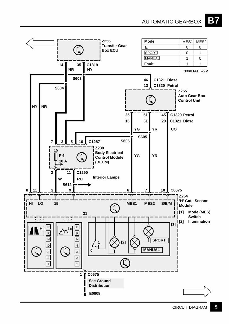
AUTOMATIC GEARBOX B7
5CIRCUIT DIAGRAM
7
8
Z256Transfer GearBox ECU
S604
S603
35 C131914NYNR
Z238Body ElectricalControl Module(BECM)
S612
11 C12902
RUW
15F 610 A
Z255Auto Gear BoxControl Unit
45 C132051
UOYR
3 16 C12875
Z254’H’ Gate SensorModule
[1] Mode (MES)Switch
[2] Illumination
1 C0675
Hi Lo
11 2 9 7 10 C0675
25
6
13 C1320
S606S605
[2]
[1]
MANUAL
SPORT
P
R
N
D
3
2
1
P
R
N
4
3
2
1
0
1
See GroundDistribution
E0808
HI LO 15
31
MES1 MES2 S/E/M
NY NR
YG
Interior Lamps
E 0 0SPORT 0 1MANUAL 1 0
1 1
MES1 MES2
1=VBATT–2V
Mode
Fault
YRYG
46 C1321 DieselPetrol
16 31 29 C1321
Petrol
Diesel

AUTOMATIC GEARBOXB7
6 CIRCUIT DIAGRAM
UB
Z254’H’ Gate SensorModule
O
O
O
O
O
O
O
Note! Status of X,Y, Z Switchesonly affects RedIllumination dots
P
R
N
D
3
2
1
X Y Z
S610
S609
18 C12879
UGUP
8
UB
Z238Body ElectricalControl Module(BECM)
S608
UP UG
See GroundDistribution
E0808
6 C0244
BG
2 C0988C0745
X Y Z
[1] [2] [3]
0 0 0
3 C024421
4 5C0745C0988
33 C13211450
Z255Auto Gear BoxControl Unit
HI P 0 1 1R 0 0 1N 1 0 1
D 1 0 03 0 0 02 0 1 01 1 1 0Z* 1 1 1
X Y Z
1 =
0 =
* =
Switch OpenSwitch ClosedFault
36 8 37 C1320DieselPetrol
3
5 C06754 3
X294Gear BoxPosition Switch
[1] X Switch[2] Y Switch[3] Z Switch

AUTOMATIC GEARBOX B7
7CIRCUIT DIAGRAM
M
1 0 12 1 13 1 04 0 0
MV1 MV2
1 =
0 =
Z255Auto Gear BoxControl Unit
53 C1320
6C0988C0745
SO
Z255Auto Gear BoxControl Unit
Z263Gearbox Case
[1] MV1Solenoid
[2] MV2Solenoid
[3] ConverterLock UpSolenoid
[4] PressureRegulatorSolenoid
[5] OutputShaft SpeedSensor
Solenoid Energized
Solenoid NotEnergized
[1] [2] [3] [4]
B
30
K
10 11
H
12C0988C0745 13
D C0243
14C0988C0745
14 C1320
E
SCR
SCR
15
SCR
+
–
[5]
L C0243
OP OW SO OG
K Y
Gear
Z269Output ShaftSpeed SensorShield
19 C1321
Petrol
Diesel
S554
5 24 42 6 20 2 38 C1321 Diesel
Petrol
9
32 1533 5 42
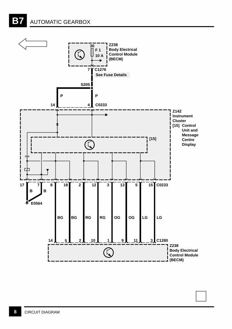
AUTOMATIC GEARBOXB7
8 CIRCUIT DIAGRAM
Z238Body ElectricalControl Module(BECM)
S205
30F 110 A
Z142InstrumentCluster[15] Control
Unit andMessageCentreDisplay
[15]
8 18
14 5
2 12
2 10
3 13
1 9
5 15
11
17 7
Z238Body ElectricalControl Module(BECM)
E0564
7 C1276
C0233
C12803
BG BG RG RG OG OG LG LG
B B
PP
See Fuse Details
4 C023314
IGNITION AND SHIFT INTERLOCK C1
CIRCUIT OPERATION 1
Circuit Operation
Selector Interlock
The Gear Selector Lever may only be moved out ofthe Park position when the ignition is on and thebrake pedal is depressed. The Shift Lock Solenoidshall be energised continuously whilst the Ignition ison and the Gear Selector Lever is in a position otherthan Park or Neutral.
Ignition Key Interlock
The Ignition Key Lock Solenoid shall at all timesprevent removal of the Key from the Ignition Switchunless the Gear Selector Lever is in the Parkposition.
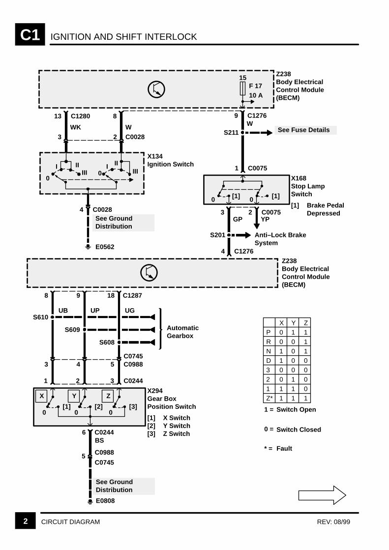
IGNITION AND SHIFT INTERLOCKC1
2 CIRCUIT DIAGRAM REV: 08/99
P 0 1 1
R 0 0 1N 1 0 1D 1 0 03 0 0 02 0 1 01 1 1 0Z* 1 1 1
X Y Z
Z238Body ElectricalControl Module(BECM)
Z238Body ElectricalControl Module(BECM)
9 C1276W
15
1 C0075
[1]
X168Stop LampSwitch
[1] Brake PedalDepressed
0 [1]0
S211 See Fuse Details
13 C1280
WK
X134Ignition Switch
8
W
0
I IIIII 0
I IIIII
3 2 C0028
See GroundDistribution
E0562
4 C0028 3GP
4 C1276
S201
2 C0075YP
Anti–Lock BrakeSystem
F 1710 A
1 =
0 =
* =
Switch Open
Switch Closed
Fault
8
UB
1
X294Gear BoxPosition Switch
[1] X Switch[2] Y Switch[3] Z Switch
[1]0
9
UP
2
See GroundDistribution
6BS
E0808
C0244
[2]0
5C0745
43
18 C1287
UG
3
[3]0
C0244
5 C0988
S608
S609
S610
AutomaticGearbox
C0988
C0745
X Y Z
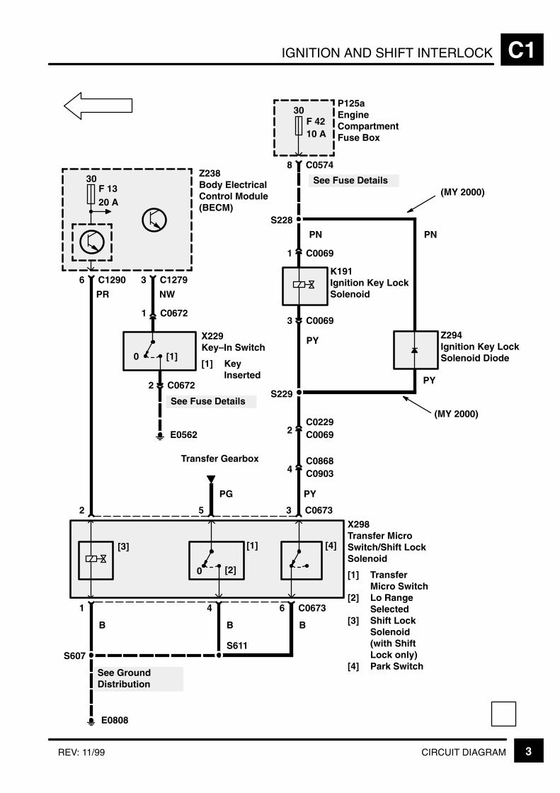
IGNITION AND SHIFT INTERLOCK C1
3CIRCUIT DIAGRAMREV: 11/99
See Fuse Details
X298Transfer MicroSwitch/Shift LockSolenoid
[1] TransferMicro Switch
[2] Lo RangeSelected
[3] Shift LockSolenoid(with ShiftLock only)
[4] Park Switch
PR
Transfer Gearbox
6 C1290
0 [2]
Z238Body ElectricalControl Module(BECM)
[1][3]
2 5
1
B
S607
E0808
4
B
S611
See GroundDistribution
NW
3 C1279
0 [1]
1 C0672
X229Key–In Switch
[1] KeyInserted
PG
30F 1320 A
[4]
3 C0673
6 C0673
B
PY
P125aEngineCompartmentFuse Box
8 C0574
1 C0069
K191Ignition Key LockSolenoid
PY
3 C0069
30
10 AF 42
2C0229C0069
4C0868C0903
2 C0672
E0562
See Fuse Details
Z294Ignition Key LockSolenoid Diode
S228
S229
PN
(MY 2000)
(MY 2000)
PN
PY

KEY INFORMATIONi
!"
#$ % &'( ' )
*$ % &'( + %
,# % &'( ' )
% &'( ' )
-
*, !+
!
+ ' '
+ .) . . '
/+ +0 .
' /'+0
"% ) '
+ ) . % .
+ +- %
. )
(
.
!"
. ' % 1(
2 + " .
' ) '
2 +' 3 .
.' % '
2 .) % '
2 4 .' % '-
&+
+ )
+ /0 .
+ ' %

ANTI-LOCK BRAKE SYSTEM D1
CIRCUIT OPERATION 1REV: 11/2000
CIRCUIT OPERATION
The Anti–lock Braking System (ABS) prevents wheellock–up during braking. This enables the driver tomaintain vehicle stability and steering control whilebraking.
The Electronic Traction Control (ETC) systemprevents wheel slip to maintain optimum traction onslippery surfaces. Up to 99 Model Year, ETCoperates only on the rear wheels at vehicle speedsbelow 50 km/h (30 mph). From 99 Model Year, ETCoperates on all four wheels at vehicle speeds below100 km/h (62.5 mph).
Anti–lock Braking System Electronic Control Unit(ECU) (Z108)
The ABS ECU (Z108) is a computer that controlsABS operation by permanently monitoring thevehicle’s four wheel speeds when the ignition switchis in position II. If an impending wheel lock–up isdetected during this monitoring, the ABS ECU willapply voltage to the applicable inlet and outlet valvesolenoids contained in the ABS Booster Unit (Z103).Operation of the solenoid valves regulates thepressure applied to the brake caliper and preventswheel lock–up.
ETC is an extension to the ABS ECU. In addition tomonitoring the wheel speeds for lock–up, the ABSECU also monitors wheel speeds for wheel slip (i.e.wheel speed faster than vehicle speed). When wheelslip is detected, the ABS ECU will apply brakingpressure to the slipping wheel(s), causing the wheelspeed to slow to vehicle speed and torque to betransferred to the non–slipping wheel(s). The ABSECU applies the brake by operating the applicableinlet and outlet solenoid valves in the ABS BoosterUnit.
The ABS ECU has diagnostic capabilities that allowit to detect faults that may impair the system’sefficiency. If a fault occurs, the ECU adopts a defaultstrategy which illuminates the ABS or the TCwarning light in the instrument cluster (Z142) andstores a fault code in its memory to aid systemtroubleshooting. When an ABS fault has beendetected, the message ABS FAULT may also bedisplayed in the instrument cluster message centre.When an ETC fault has been detected, the messageTRACTION FAILURE is displayed and on the firstdetected fault a single audible chime sounds. Faultcodes stored in the ECU memory can be retrievedusing Testbook or a universal scan tool.
The ABS ECU also performs a bulb check of thewarning lights when the ignition switch is first turnedto position II. The ABS warning light is illuminated for1 second, extinguished for 0.5 seconds andilluminated again until the ECU receives an inputspeed of 7 km/h (5 mph) from all four wheel speedsensors (X137, X140, X1158, X161) and is thenextinguished. The TC warning light is illuminated for3 seconds and then extinguished. If a system fault isdetected during the bulb check the ABS or the TCwarning light remain illuminated.
When ETC is activated, the TC warning lightilluminates, a single audible chime sounds and onearlier models, the message TRACTION isdisplayed. The message and warning light extinguishafter 2 seconds minimum or when ETC isde–activated. If ETC is continuously or repeatedlyactive and there is a risk of the brakes overheatingthe ABS ECU disables the ETC. To advise the driverof the disablement, the ETC warning light flashes for10 seconds minimum, a single audible chime soundsand the message TRACTION OVERHEAT isdisplayed. The ABS ECU restores ETC availabilityafter allowing time for the brakes to cool.
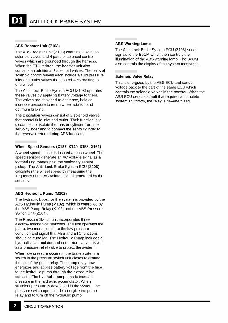
ANTI-LOCK BRAKE SYSTEMD1
CIRCUIT OPERATION2
ABS Booster Unit (Z103)
The ABS Booster Unit (Z103) contains 2 isolationsolenoid valves and 4 pairs of solenoid controlvalves which are grounded through the harness.When the ETC is fitted, the booster unit alsocontains an additional 2 solenoid valves. The pairs ofsolenoid control valves each include a fluid pressureinlet and outlet valves that control ABS braking toone wheel.
The Anti–Lock Brake System ECU (Z108) operatesthese valves by applying battery voltage to them.The valves are designed to decrease, hold orincrease pressure to retain wheel rotation andoptimum braking.
The 2 isolation valves consist of 2 solenoid valvesthat control fluid inlet and outlet. Their function is todisconnect or isolate the master cylinder from theservo cylinder and to connect the servo cylinder tothe reservoir return during ABS functions.
Wheel Speed Sensors (X137, X140, X158, X161)
A wheel speed sensor is located at each wheel. Thespeed sensors generate an AC voltage signal as atoothed ring rotates past the stationary sensorpickup. The Anti–Lock Brake System ECU (Z108)calculates the wheel speed by measuring thefrequency of the AC voltage signal generated by thesensors.
ABS Hydraulic Pump (M102)
The hydraulic boost for the system is provided by theABS Hydraulic Pump (M102), which is controlled bythe ABS Pump Relay (K102) and the ABS PressureSwitch Unit (Z104).
The Pressure Switch unit incorporates threeelectro– mechanical switches. The first operates thepump, two more illuminate the low pressurecondition and signal that ABS and ETC functionsshould be curtailed. The Hydraulic Pump includes ahydraulic accumulator and non–return valve, as wellas a pressure relief valve to protect the system.
When low pressure occurs in the brake system, aswitch in the pressure switch unit closes to groundthe coil of the pump relay. The pump relay nowenergizes and applies battery voltage from the fuseto the hydraulic pump through the closed relaycontacts. The hydraulic pump runs to increasepressure in the hydraulic accumulator. Whensufficient pressure is developed in the system, thepressure switch opens to de–energize the pumprelay and to turn off the hydraulic pump.
ABS Warning Lamp
The Anti–Lock Brake System ECU (Z108) sendssignals to the BeCM which then controls theillumination of the ABS warning lamp. The BeCMalso controls the display of the system messages.
Solenoid Valve Relay
This is energized by the ABS ECU and sendsvoltage back to the part of the same ECU whichcontrols the solenoid valves in the booster. When theABS ECU detects a fault that requires a completesystem shutdown, the relay is de–energized.
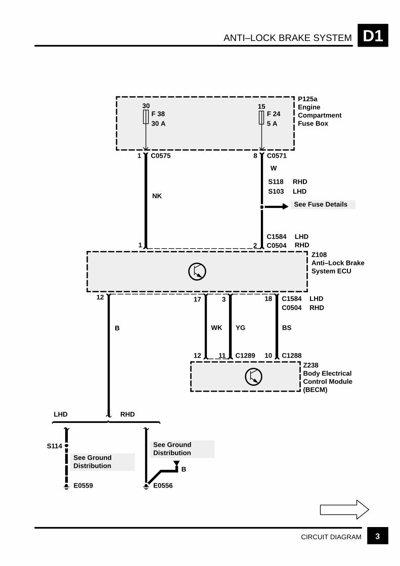
ANTI–LOCK BRAKE SYSTEM D1
3CIRCUIT DIAGRAM
B
P125aEngineCompartmentFuse Box
30F 3830 A
15F 245 A
NK
1 C0575
W
8 C0571
S118
See Fuse Details
B
12
S114
E0559
See GroundDistribution
E0556
WK
17
12
YG
3
11 C1289
BS
10 C1288
LHD
See GroundDistribution
RHD
1 2 C0504C1584
Z108Anti–Lock BrakeSystem ECU
Z238Body ElectricalControl Module(BECM)
S103RHDLHD
LHDRHD
LHDRHD
18 C1584C0504
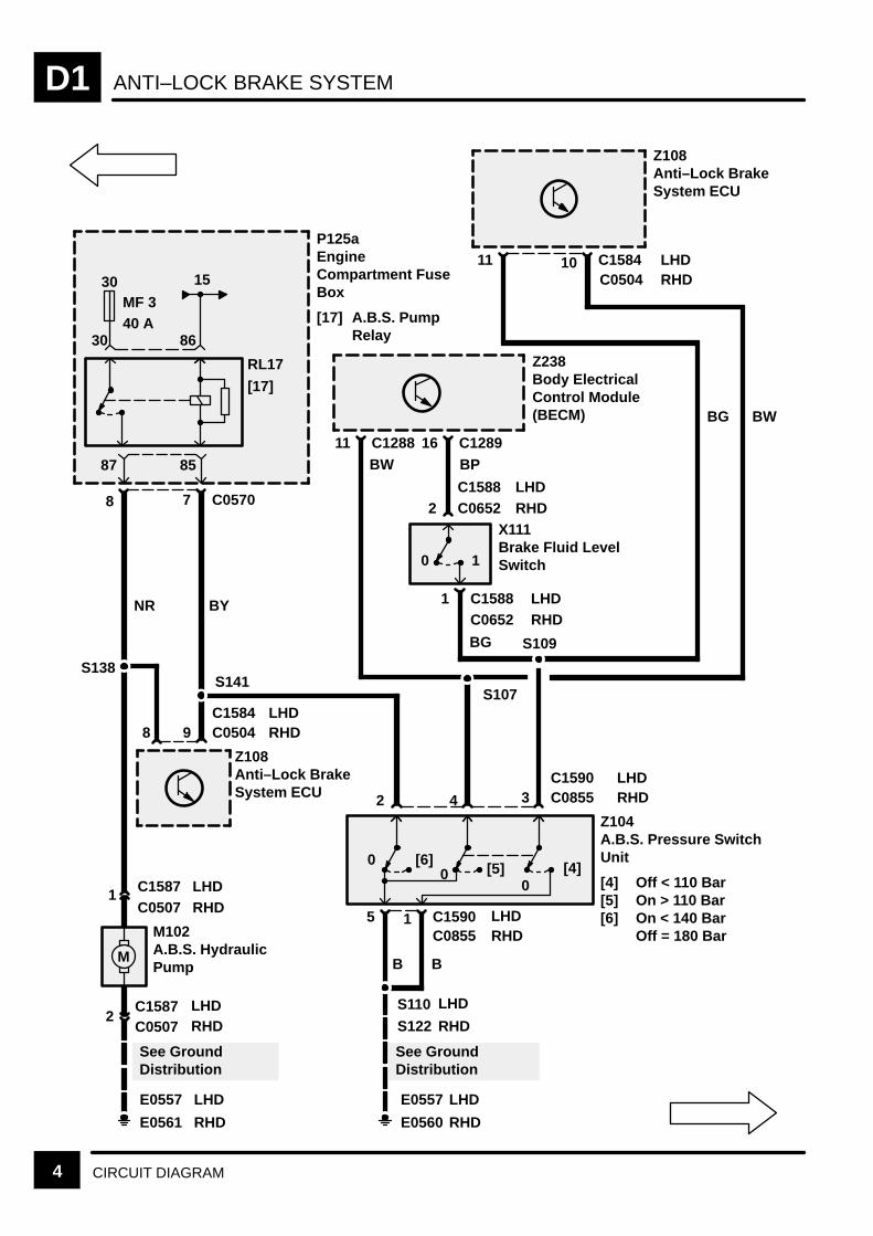
ANTI–LOCK BRAKE SYSTEMD1
4 CIRCUIT DIAGRAM
RL17
[17]
BY
7 C0570
30MF 340 A
8
30 86
8587
15
P125aEngineCompartment FuseBox
[17] A.B.S. PumpRelay
11
Z108Anti–Lock BrakeSystem ECU
S110
E0560
See GroundDistribution
BW
10 C1584
11 C1288
Z238Body ElectricalControl Module(BECM)
BP16 C1289
0 1
BW
0 [6]0
0[4][5]
5
B
1 C1590
B
C0855
Z104A.B.S. Pressure SwitchUnit
[4] Off < 110 Bar[5] On > 110 Bar[6] On < 140 Bar
Off = 180 BarM
E0561
See GroundDistribution
E0557
2C1587C0507
1C0507C1587
M102A.B.S. HydraulicPump
BG S109
NR
BG
X111Brake Fluid LevelSwitch
2 4
S122
E0557
LHDRHD
LHDRHD
LHDRHD
LHDRHD
LHDRHD
LHDRHD
LHDRHD
LHD
RHD
LHD
RHD
LHD
RHD
S107
Z108Anti–Lock BrakeSystem ECU
S141S138
9 C0504 RHD8
3 C0855C1590
1 C1588C0652
2 C0652C1588
C1584 LHD
C0504

ANTI–LOCK BRAKE SYSTEM D1
5CIRCUIT DIAGRAM
Z238Body ElectricalControl Module(BECM)
0 0 [1][1]
YP
X168Stop LampSwitch
[1] Brake PedalDepressed
1 C0075
15F 1710 A
9 C1276
2 C0075
A
D1-6
3
S201
4 C1276 5 C0239Z238Body ElectricalControl Module(BECM)
Z121Cruise ControlECU
S106
3C0448
S131
7 C0504Z108Anti–Lock BrakeSystem ECU
S106
3C0448
7 C1584Z108Anti–Lock BrakeSystem ECU
31 C0867Z165Air SuspensionECU
26 C0411Z132Engine ControlModule (ECM)
C0203
W
GP
GP GP
Petrol
DieselDiesel
RHD LHD
Diesel
14 C0229C0067
C0203
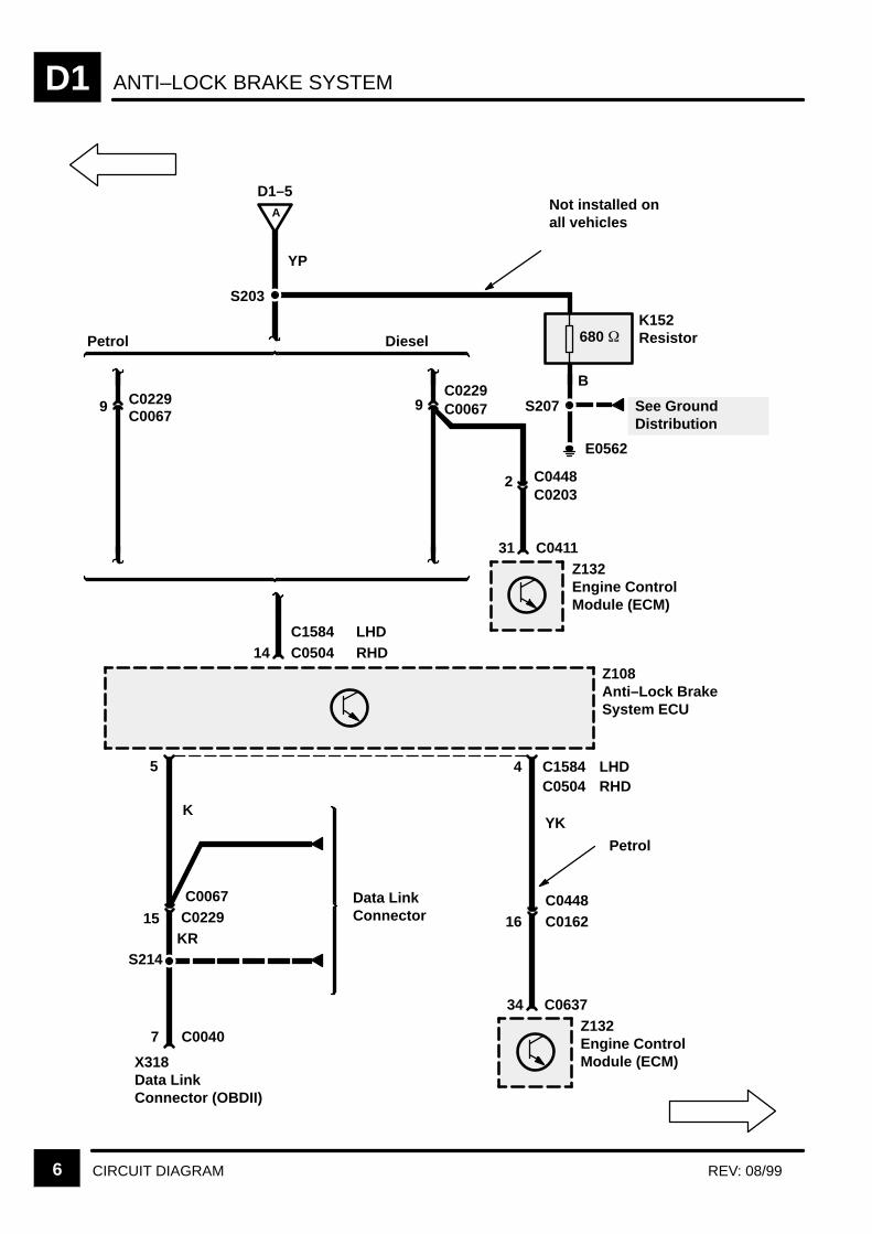
ANTI–LOCK BRAKE SYSTEMD1
6 CIRCUIT DIAGRAM REV: 08/99
S203
9 C0229
31 C0411Z132Engine ControlModule (ECM)
C0067
B
A
D1–5
YP
9C0229C0067
680 K152Resistor
S207
E0562
2 C0448C0203
14 C0504Z108Anti–Lock BrakeSystem ECU
C1584
See GroundDistribution
LHDRHD
Petrol Diesel
Not installed onall vehicles
4
16
YK
C0504C1584 LHD
RHD
34 C0637Z132Engine ControlModule (ECM)
Petrol
C0162C0448
5
15
S214
K
7 C0040
KR
X318Data LinkConnector (OBDII)
Data LinkConnector
C0067C0229
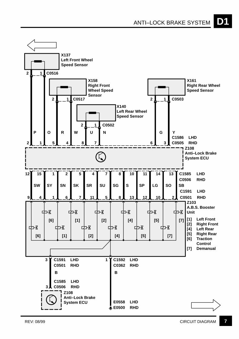
ANTI–LOCK BRAKE SYSTEM D1
7CIRCUIT DIAGRAMREV: 08/99
SOLGSPSN
X137Left Front WheelSpeed Sensor
P
2 C0516
O
X158Right FrontWheel SpeedSensor
R
2 C0517
W
X140Left Rear WheelSpeed Sensor
U
2 1 C0502
N
X161Right Rear WheelSpeed Sensor
G
2 1 C0503
Y
Z108Anti–Lock BrakeSystem ECU
[6]
SW SY SK SR SU SG S SB
15 1 2 5 4 7 8 10 11 14
9 4 1 6 7 11 5 8 13 12 10
[6]
[1]
[1]
[2]
[2]
[4]
[4]
[5]
[5]
[7]
[7]
Z103A.B.S. BoosterUnit
[1] Left Front[2] Right Front[4] Left Rear[5] Right Rear[6] Traction
Control[7] Demanual
B
1 C1592C0362
E0500
2 1 5 4 8 7 6 3 C0505C1586
LHDRHD
LHD
RHD
LHDRHD
LHDRHD
1
1
E0558RHDLHD
3 C0506Z108Anti–Lock BrakeSystem ECU
3 C1591C0501
LHDRHD
C1585 LHDRHD
B
12 13 C1585C0506
2 C0501
C1591

ANTI–LOCK BRAKE SYSTEMD1
8 CIRCUIT DIAGRAM
Z238Body ElectricalControl Module(BECM)
S205
30F 110 A
4 C023314Z142InstrumentCluster[15] Control Unit
and Mess-age CentreDisplay[15]
8 18
14 5
2 12
2 10
3 13
1 9
5 15
11
7 17
Z238Body ElectricalControl Module(BECM)
E0564
7 C1276
C0233
C12803
B B BG BG RG RG OG OG LG LG
PP
P !
BRAKE
See Fuse Details

DATA LINK CONNECTOR D3
1CIRCUIT DIAGRAM
30F 335 A
X318Data LinkConnector(OBDII)
P125aEngineCompartmentFuse Box
Z260Air SuspensionDelay Turn OffTimer
C05744
C08663
N
C006713 C0229
16
6
C00401
C0467C0469
5 4 11 12 C0040
BP
C02295 C0067
B
S207
E0562
Z165Air SuspensionECU
WLG WK
12 11 C0469C0467
35 17 C0867
SR
See GroundDistribution
See GroundDistribution
14
KW
9 C0256
Z151SRS DiagnosticControl Unit
S115
E0559
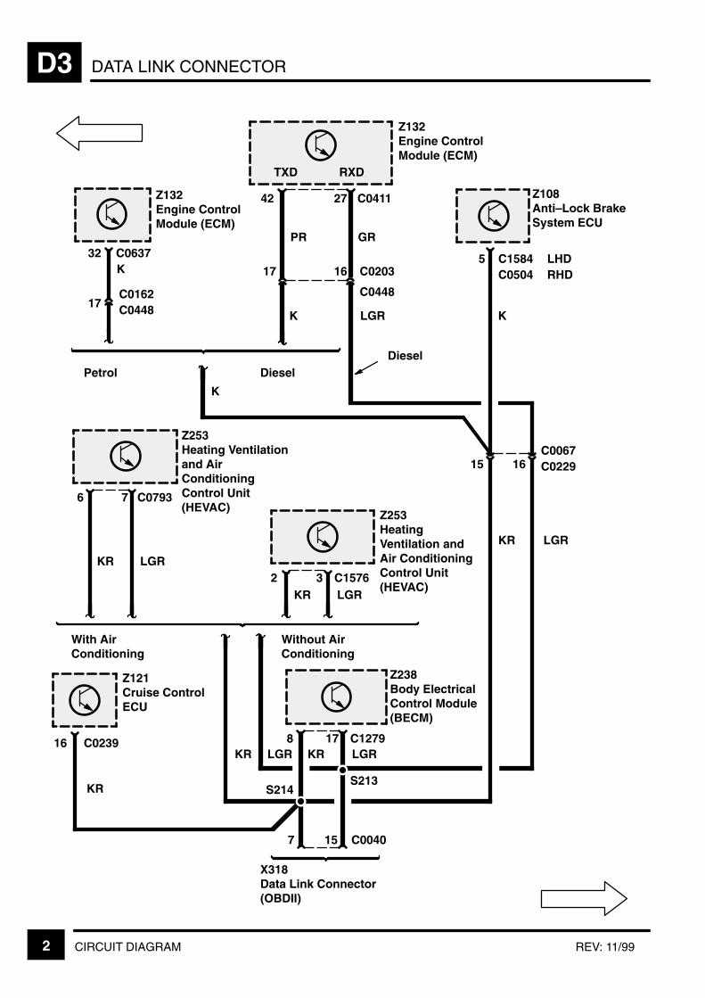
DATA LINK CONNECTORD3
2 CIRCUIT DIAGRAM REV: 11/99
LGR
Z132Engine ControlModule (ECM)
Z132Engine ControlModule (ECM)
Z108Anti–Lock BrakeSystem ECU
C0637
17
K
42 27 C0411
PR GR
17 16 C0203
C0448
K
K
Petrol Diesel
5 C1584C0504
K
15 16C0067C0229
Z253HeatingVentilation andAir ConditioningControl Unit(HEVAC)
2 3 C1576KR LGR
Z253Heating Ventilationand AirConditioningControl Unit(HEVAC)
6 7 C0793
KR LGR
With AirConditioning
Without AirConditioning
KR LGR8 17 C1279
S214S213
KR LGR
X318Data Link Connector(OBDII)
7 15 C0040
Z238Body ElectricalControl Module(BECM)
32
TXD RXD
LHDRHD
KR LGR
Z121Cruise ControlECU
16 C0239
C0162C0448
KR
Diesel

DATA LINK CONNECTOR D3
3CIRCUIT DIAGRAM
Z238Body ElectricalControl Module(BECM)
C12871
51 15 C1321
Z255Auto Gear BoxControl Unit
LG
12
KR
Diesel
31
Z255Auto Gear BoxControl Unit
C1320
Diesel Petrol


INSTRUMENTS E1
CIRCUIT OPERATION 1
CIRCUIT OPERATION
Engine Coolant Temperature Gauge
The engine coolant temperature gauge sensor hasthe capability to sense from –40C to +130C. Petroland Diesel resistance values are different.
Both Petrol and Diesel sensors are interfaced to theInstrument Cluster (Z142) from the BeCM (Z238) viathe serial data lines. The resistance value then beingrepresented by an A/D data transfer generating therequired angular deflection on this gauge. ]
Fuel Gauge
When the fuel tank level is low (“E”), the resistancevalue of the gauge sensor is 270Ω for petrol anddiesel engines. As the fuel level increases, theresistance of the sensor decreases. When the fueltank is full, the resistance value of the sensor forpetrol engines is 19Ω and for diesel engines 25.8Ω .When the fuel gauge sensors resistance valueincreases to 175Ω (9 liters/2.25 US gallons, the lowfuel warning light will illuminate to warn of the fuelstatus. Both Petrol and Diesel sensors are interfacedto the Instrument Cluster (Z142) via the BeCM(Z238). The resistance values then beingrepresented by an A/D data transfer generating therequired angular deflection on the gauge.
Speedometer
The signal to activate the gauge is originated at theABS wheel sensors, transmitted to the ABS ECU(Z108) which then puts out a usable signal to theInstrument Cluster (Z142) of 8000 pulses per mile or4972 pulses per kilometer. The signal is alsotransmitted to other ECU’s, such as the EngineControl Module (ECM) (Z132) and the Cruise ControlECU (Z121).
Tachometer
The tachometer will display the engine speed inR.P.M. It will derive the engine speed from theengine speed pulse train transmitted from the EngineControl Module (ECM) (Z132).
The pulse rate for petrol engines will be 4 pulses perengine revolution.
The pulse rate for diesel engines will be 3 pulses perengine revolution.
Audible Warning
Receipt of an audible warning request signal from avehicle parameter/message condition shall cause theBeCM (Z238) to generate the required number ofwarning tones. The actuator sounder unit is locatedat the rear of the Instrument Cluster (Z142).
See message listing for categories/priority and levelsof audible warnings.
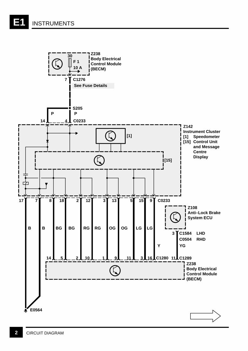
INSTRUMENTSE1
2 CIRCUIT DIAGRAM
LGLG
5
7 C1276
17
14
[15]
4 C0233
B
S205
See Fuse Details
30F 110 A
7
B
8
BG
14
18
BG
5
2
2
12
10
RG RG
1
13
9
OGOG
E0564
P P
3 C0233
11
15
3 C1280
9
Y YG
11 C1289
Z238Body ElectricalControl Module(BECM)
Z142Instrument Cluster[1] Speedometer[15] Control Unit
and MessageCentreDisplay
Z108Anti–Lock BrakeSystem ECU
Z238Body ElectricalControl Module(BECM)
[1]
3 C1584C0504
LHDRHD
16

INSTRUMENTS E1
3CIRCUIT DIAGRAM
Z142InstrumentCluster[2] Tachometer[3] Fuel Gauge[15] Control
Unit andMessageCentreDisplay
Z238Body ElectricalControl Module(BECM)
Z132Engine ControlModule (ECM)
Z132Engine ControlModule (ECM)
Z134Fuel PumpModule[1] Fuel Level
Sensor
10 16 C0233
15 8 C1280
BK S
10 C1289
GB
2 C0205
3 C0205
B
S115
E0559
17 C0637
S
PetrolDiesel
50 C0411
20C0448
C0203
S
9 C1288
[2] [3]
[15]
[1]
See GroundDistribution
1 C0204 Diesel
Petrol
2 C0204PetrolDiesel
20C0448
C0162
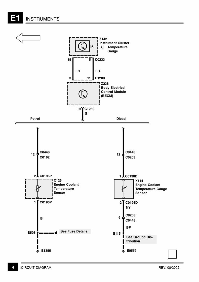
INSTRUMENTSE1
4 CIRCUIT DIAGRAM REV: 08/2002
[4]
Z142Instrument Cluster[4] Temperature
Gauge
Z238Body ElectricalControl Module(BECM)
C128919G
Petrol Diesel
C044812
C0162
C0196P2X126Engine CoolantTemperatureSensor
C0196D1X114Engine CoolantTemperature GaugeSensor
1
B
C0196P
See Ground Dis-tribution
S506
C044812
C0203
2
E0559
C0196D
C02036
C0448
S115
NY
See Fuse Details
E1355
BP
15 5 C0233
3 11 C1280
LG LG
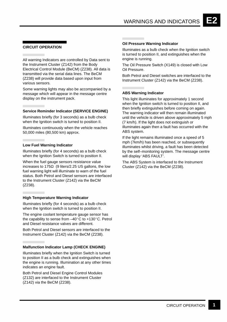
WARNINGS AND INDICATORS E2
CIRCUIT OPERATION 1
CIRCUIT OPERATION
All warning Indicators are controlled by Data sent tothe Instrument Cluster (Z142) from the BodyElectrical Control Module (BeCM) (Z238). All data istransmitted via the serial data lines. The BeCM(Z238) will provide data based upon input fromvarious sensors.
Some warning lights may also be accompanied by amessage which will appear in the message centredisplay on the instrument pack.
Service Reminder Indicator (SERVICE ENGINE)
Illuminates briefly (for 3 seconds) as a bulb checkwhen the Ignition switch is turned to position II.
Illuminates continuously when the vehicle reaches50,000 miles (80,500 km) approx.
Low Fuel Warning Indicator
Illuminates briefly (for 4 seconds) as a bulb checkwhen the Ignition Switch is turned to position II.
When the fuel gauge sensors resistance valueincreases to 175Ω (9 liters/2.25 US gallons, the lowfuel warning light will illuminate to warn of the fuelstatus. Both Petrol and Diesel sensors are interfacedto the Instrument Cluster (Z142) via the BeCM(Z238).
High Temperature Warning Indicator
Illuminates briefly (for 4 seconds) as a bulb checkwhen the Ignition switch is turned to position II.
The engine coolant temperature gauge sensor hasthe capability to sense from –40C to +130C. Petroland Diesel resistance valves are different.
Both Petrol and Diesel sensors are interfaced to theInstrument Cluster (Z142) via the BeCM (Z238).
Malfunction Indicator Lamp (CHECK ENGINE)
Illuminates briefly when the Ignition Switch is turnedto position II as a bulb check and extinguishes whenthe engine is running. Illumination at any other timesindicates an engine fault.
Both Petrol and Diesel Engine Control Modules(Z132) are interfaced to the Instrument Cluster(Z142) via the BeCM (Z238).
Oil Pressure Warning Indicator
Illuminates as a bulb check when the Ignition switchis turned to position II, and extinguishes when theengine is running.
The Oil Pressure Switch (X149) is closed with LowOil Pressure.
Both Petrol and Diesel switches are interfaced to theInstrument Cluster (Z142) via the BeCM (Z238).
ABS Warning Indicator
This light illuminates for approximately 1 secondwhen the Ignition switch is turned to position II, andthen briefly extinguishes before coming on again.The warning indicator will then remain illuminateduntil the vehicle is driven above approximately 5 mph(7 km/h). If the light does not extinguish orilluminates again then a fault has occurred with theABS system.
If the light remains illuminated once a speed of 5mph (7km/h) has been reached, or subsequentlyilluminates whilst driving, a fault has been detectedby the self–monitoring system. The message centrewill display ABS FAULT.
The ABS System is interfaced to the InstrumentCluster (Z142) via the BeCM (Z238).

WARNINGS AND INDICATORSE2
CIRCUIT OPERATION2
ETC Warning Indicator (TC)
Illuminates for 3 seconds after the Ignition switch isturned on and the ABS and traction control systemshave completed their self–checks.
Whilst driving, the TC light will illuminate (for aminimum of 2 seconds) whenever traction control isactive; the light extinguishing as soon as tractioncontrol ceases. The light flashing (for at least 10seconds) indicates that the system has beenover–used; it will be available again once the systemcomponents have cooled.
If the light illuminates continuously, a fault with thesystem is indicated.
The ABS System is interfaced to the InstrumentCluster (Z142) via the BeCM (Z238).
Brake Warning Indicator
Illuminates for 3 seconds as a bulb check when theIgnition switch is turned to position II and alsoilluminates when the handbrake is applied and theIgnition switch is in position II.
The light should extinguish when the handbrake isfully released or after the bulb check if thehandbrake is off. If the light illuminates whilst driving,a fault is indicated.
NOTE: If the vehicle has been standing for sometime, it may take up to 40 seconds before the lightextinguishes (in this case, ABS and TC warninglights will also be illuminated).
The Brake System and Handbrake Switch (X191)are interfaced to the Instrument Cluster (Z142) viathe BeCM (Z238).
Cruise Active Indicator
When the Cruise Control System has been activatedthe indicator will be illuminated. The Cruise Systemis interfaced to the Instrument Cluster (Z142) via theBeCM (Z238).
Charge Warning Indicator
Illuminates as a bulb check when the Ignition switchis turned to position II and extinguishes when theengine is running and the Generator (Z106) isproducing normal power. If the Generator (Z106) isnot producing normal power or the Generator (Z106)stops turning the indicator will illuminate.
Both Petrol and Diesel Generators (Z106) areinterfaced to the Instrument Cluster (Z142) via theBeCM (Z238).
Fasten Seat Belt Indicator
Illuminates for 6 seconds when the Ignition switch isturned to position II. When the driver’s seat belt isbuckled, the indicator turns off.
The Driver’s Seat Belt Switch (X120) is interfaced tothe Instrument Cluster (Z142) via the BeCM (Z238).
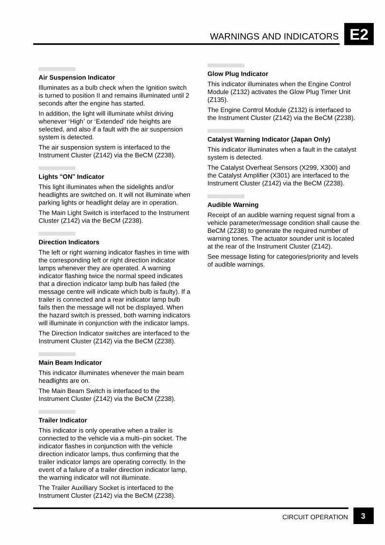
WARNINGS AND INDICATORS E2
CIRCUIT OPERATION 3
Air Suspension Indicator
Illuminates as a bulb check when the Ignition switchis turned to position II and remains illuminated until 2seconds after the engine has started.
In addition, the light will illuminate whilst drivingwhenever High or Extended ride heights areselected, and also if a fault with the air suspensionsystem is detected.
The air suspension system is interfaced to theInstrument Cluster (Z142) via the BeCM (Z238).
Lights ON Indicator
This light illuminates when the sidelights and/orheadlights are switched on. It will not illuminate whenparking lights or headlight delay are in operation.
The Main Light Switch is interfaced to the InstrumentCluster (Z142) via the BeCM (Z238).
Direction Indicators
The left or right warning indicator flashes in time withthe corresponding left or right direction indicatorlamps whenever they are operated. A warningindicator flashing twice the normal speed indicatesthat a direction indicator lamp bulb has failed (themessage centre will indicate which bulb is faulty). If atrailer is connected and a rear indicator lamp bulbfails then the message will not be displayed. Whenthe hazard switch is pressed, both warning indicatorswill illuminate in conjunction with the indicator lamps.
The Direction Indicator switches are interfaced to theInstrument Cluster (Z142) via the BeCM (Z238).
Main Beam Indicator
This indicator illuminates whenever the main beamheadlights are on.
The Main Beam Switch is interfaced to theInstrument Cluster (Z142) via the BeCM (Z238).
Trailer Indicator
This indicator is only operative when a trailer isconnected to the vehicle via a multi–pin socket. Theindicator flashes in conjunction with the vehicledirection indicator lamps, thus confirming that thetrailer indicator lamps are operating correctly. In theevent of a failure of a trailer direction indicator lamp,the warning indicator will not illuminate.
The Trailer Auxilliary Socket is interfaced to theInstrument Cluster (Z142) via the BeCM (Z238).
Glow Plug Indicator
This indicator illuminates when the Engine ControlModule (Z132) activates the Glow Plug Timer Unit(Z135).
The Engine Control Module (Z132) is interfaced tothe Instrument Cluster (Z142) via the BeCM (Z238).
Catalyst Warning Indicator (Japan Only)
This indicator illuminates when a fault in the catalystsystem is detected.
The Catalyst Overheat Sensors (X299, X300) andthe Catalyst Amplifier (X301) are interfaced to theInstrument Cluster (Z142) via the BeCM (Z238).
Audible Warning
Receipt of an audible warning request signal from avehicle parameter/message condition shall cause theBeCM (Z238) to generate the required number ofwarning tones. The actuator sounder unit is locatedat the rear of the Instrument Cluster (Z142).
See message listing for categories/priority and levelsof audible warnings.

WARNINGS AND INDICATORSE2
4 CIRCUIT DIAGRAM
7 C1276
4 C0233
S205
See Fuse Details
30F 110 A
Z253HeatingVentilation andAirConditioningControl Unit(HEVAC)
Z253HeatingVentilation andAirConditioningControl Unit(HEVAC)
C079311
O
C15761
O
With AirConditioning
Without AirConditioning
Z238Body ElectricalControl Module(BECM)
Interior Lamps
RW P
6 20 14
E2-5
Z142Instrument Cluster[13] Illumination[15] Control Unit
and MessageCentre Display
30 30
[13]
[15]
17 7 8 18 2 12 3 13 5 15 10 C0233BK
14 5 2 10 1 9 11 3 15 C1280
Z238Body ElectricalControl Module(BECM)
E0564
A
LCD
LGLGOGOGRGRGBGBGBB
[13]
P
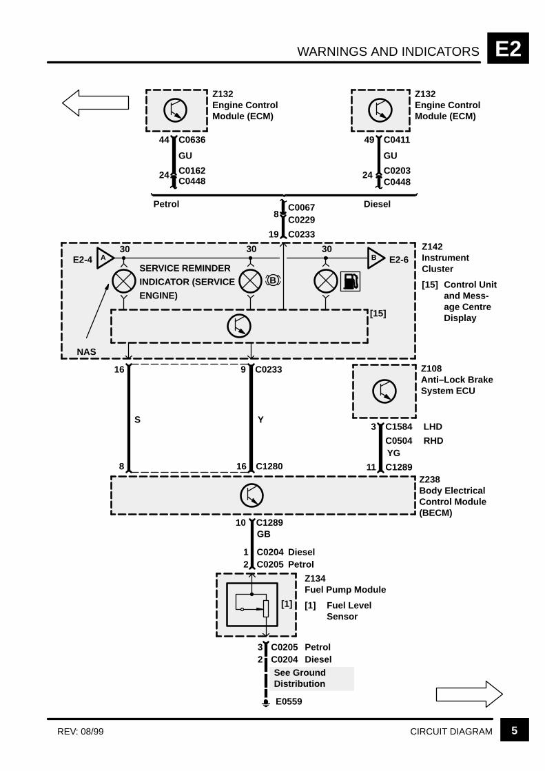
WARNINGS AND INDICATORS E2
5CIRCUIT DIAGRAMREV: 08/99
44 C0636
GU
24C0448C0162
Z132Engine ControlModule (ECM)
49 C0411
GU
24C0448C0203
Z132Engine ControlModule (ECM)
8C0229C0067
Z142InstrumentCluster
[15] Control Unitand Mess-age CentreDisplay
AE2-4 B E2-6SERVICE REMINDER
INDICATOR (SERVICE
ENGINE)
30 30 30
[15]
NAS
19 C0233
Petrol Diesel
9 C023316
[1]
Z134Fuel Pump Module
[1] Fuel LevelSensor
C02052
8 16 C1280
3 C1584
YG
Z108Anti–Lock BrakeSystem ECU
11 C1289
GB10 C1289
C0504
LHD
RHD
YS
Z238Body ElectricalControl Module(BECM)
B
See GroundDistribution
C02041 DieselPetrol
E0559
C02042C02053 Petrol
Diesel
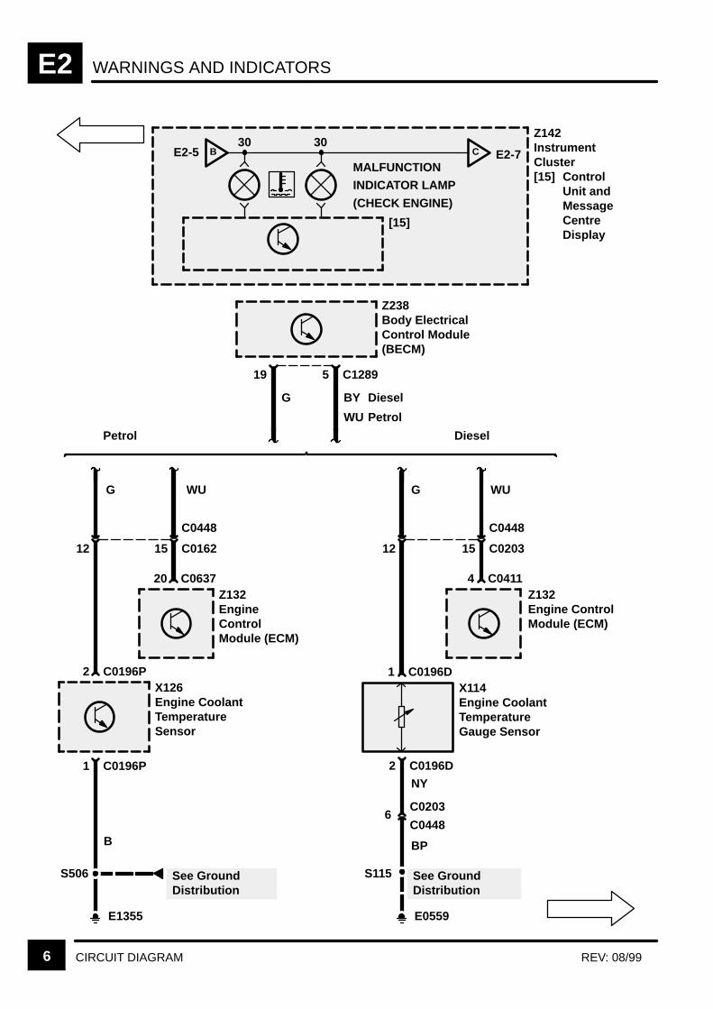
WARNINGS AND INDICATORSE2
6 CIRCUIT DIAGRAM REV: 08/99
[15]
Z142InstrumentCluster[15] Control
Unit andMessageCentreDisplay
Z238Body ElectricalControl Module(BECM)
19
G
Petrol Diesel
C0196P2X126Engine CoolantTemperatureSensor
12
C0448
15 C0203
G WU
C04114Z132Engine ControlModule (ECM)
G
C063720Z132EngineControlModule (ECM)
WU
C12895
BY
WU Petrol
Diesel
MALFUNCTION
INDICATOR LAMP
(CHECK ENGINE)
C E2-7BE2-530 30
C0196P1
B
E1355
S506 See GroundDistribution
C0196D1X114Engine CoolantTemperatureGauge Sensor
See GroundDistribution
2
E0559
C0196D
C02036
C0448
S115
NY
12
C0448
15 C0162
BP
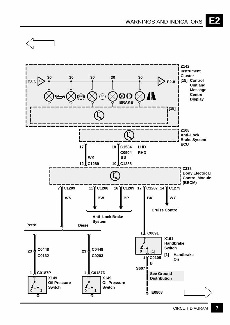
WARNINGS AND INDICATORS E2
7CIRCUIT DIAGRAM
[15]
Z142InstrumentCluster[15] Control
Unit andMessageCentreDisplay
D E2-8CE2-6
P !
BRAKE
C0187P
Z238Body ElectricalControl Module(BECM)
X149Oil PressureSwitch
0 1
1 C0091X191HandbrakeSwitch
[1] HandbrakeOn
0 [1]23 C0448
C0162
S607
C0105B
See GroundDistribution
E0808
17 C1287
BK
14 C1279
WY
Cruise Control
7 C1289
WN
30 30 30 30 30
1
12 C1289
17
10 C1288
C1584C0504BSWK
LHDRHD
Z108Anti–LockBrake SystemECU
18
1
Petrol
C0187DX149Oil PressureSwitch
0 1
23 C0448
C0203
1
Diesel
11 C1288
BW
Anti–Lock BrakeSystem
16 C1289
BP

WARNINGS AND INDICATORSE2
8 CIRCUIT DIAGRAM
[15]
Z142InstrumentCluster[15] Control
Unit andMessageCentreDisplay
E E2-9DE2-7
Z238Body ElectricalControl Module(BECM)
X120Driver’s SeatBuckle Switch
[1] Buckled0 [1]
See GroundDistribution
E0808
19 C1287
WB
Petrol
9
UK
Air Suspension
C1289
UW
30 30 30 30
Not used
8
PB
18
C02621
C02622
Z106Generator
D+
25 C0162C0448
NY
Z106Generator
D+
25 C0203C0448
NY
S573NY
Starting andCharging
C128915Diesel
C0185 C0226D
S137
NY
PowerDistribution
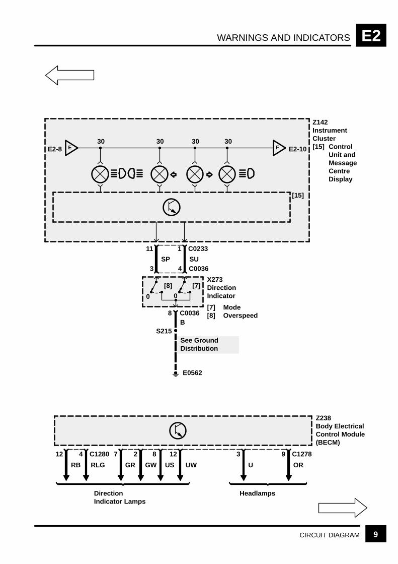
WARNINGS AND INDICATORS E2
9CIRCUIT DIAGRAM
[15]
Z142InstrumentCluster[15] Control
Unit andMessageCentreDisplay
F E2-10EE2-8
4 C0036
X273DirectionIndicator
[7] Mode[8] Overspeed
0
[7]
S215
C0036B
See GroundDistribution
E0562
1 C0233
SU
30 30 30 30
0
[8]
8
3
11
SP
Z238Body ElectricalControl Module(BECM)
12
RB
DirectionIndicator Lamps
4 C1280
RLG
3
U
Headlamps
9 C1278
OR
7 2 128
UWUSGWGR

WARNINGS AND INDICATORSE2
10 CIRCUIT DIAGRAM REV: 08/99
[15]
Z142InstrumentCluster[6] SRS
WarningLamp 1
[7] SRSWarningLamp 2
[15] ControlUnit andMessageCentreDisplay
FE2-9
7 C0256
Z151SRS DiagnosticControl Unit
5 C0230YR
30 30
33
3S
Z238Body ElectricalControl Module(BECM)
RB
Trailer AuxiliarySocket
3 C1284 C128315 3
RYGY
15F 2310 A
P125aEngineCompartmentFuse Box
3 C0576
G
18C0067C0229
1 C0230
Japan only
[7][6]
GN
5 C1291 14
GR
12
GPRY GP
10
RWRW
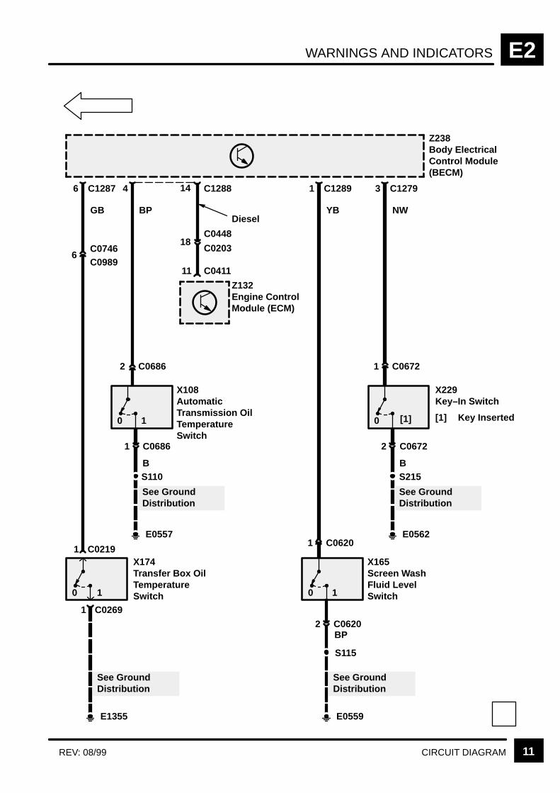
WARNINGS AND INDICATORS E2
11CIRCUIT DIAGRAMREV: 08/99
Z238Body ElectricalControl Module(BECM)
X108AutomaticTransmission OilTemperatureSwitch
0 1
See GroundDistribution
E0557
BP
C06861
C06862
4
X165Screen WashFluid LevelSwitch0 1
YB
C06202
C06201
1 C1289
X174Transfer Box OilTemperatureSwitch0 1
See GroundDistribution
E1355
GB
C07466
6 C1287
C0989
1 C0219
1 C0269
S110B
See GroundDistribution
E0559
S115
BP
X229Key–In Switch
[1] Key Inserted0 [1]
See GroundDistribution
E0562
NW
C06722
C06721
3 C1279
S215B
Z132Engine ControlModule (ECM)
11 C0411
18C0448
C0203
14 C1288
Diesel

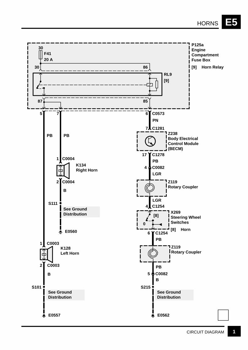
HORNS E5
1CIRCUIT DIAGRAM
30F4120 A
P125aEngineCompartmentFuse Box
[9] Horn Relay30 86
8587
RL9
[9]
1 C0003
E0557
2 C0003
B
S101
K128Left Horn
PB
1 C0004
E0560
2 C0004
B
S111
K134Right Horn
See GroundDistribution
See GroundDistribution
PB
5 7 6 C0573
PN
7 C1281Z238Body ElectricalControl Module(BECM)
17 C1278
PB
4 C0082
LGR
Z119Rotary Coupler
4 C1254X269Steering WheelSwitches
[8] Horn0
[8]
6 C1254
PB
PB
Z119Rotary Coupler
E0562
S215See GroundDistribution
5 C0082B
LGR

RADIO E6
CIRCUIT OPERATION 1REV: 09/2001
CIRCUIT OPERATION
Battery Voltage is provided to the radio at all timesthrough the P wire. In addition to the anti–theftfeature, this input voltage keeps the preset stationmemory alive. Whenever battery power to the unit islost, the anti–theft code must be entered and thepreset stations must be reprogrammed (if enabled).
When the Radio (Z111) and the igntion are turnedon, the voltage signal through the WK wire to thecontrol head ‘wakes up’ the unit. The Radio (Z111)plays, the LCD display comes on and the controlbuttons illuminate. On some models, when the parklamps or headlamps are turned on, a voltage signalis sent through the RW wire to dim the LCD displayand control buttons for night driving.
Radio (Z111) signals are received via a coaxial cablefrom the side screens and antenna amplifiers. Theamplifiers filter and boost the signal from the sidescreen, using power supplied on WO wires,whenever the ignition switch (X274) is in position I orII.
The CD Changer (Z114) is permanently suppliedwith power through the P wire via the radio and aDIN cable.
The high line (NAS/JAPAN) radio has the followingfeatures: Electronically tuned AM/FM cassette radio(Z111), RH antenna amplifier (Z178) for AM/FMsignals, LH antenna amplifier (Z177) for FM signalsonly, a subwoofer amplifier (Z176), a CD changer(Z114) a Digital Signal Processor (DSP) amplifier(Z293) and 10 speakers plus a subwoofer speaker(K146).
Subwoofer
The subwoofer amplifies frequencies between 20and 150 Hz to give an enhanced bass sound.
Subwoofer Amplifier
The subwoofer (K146) is supplied with power andground from the Subwoofer Amplifier (Z176) via twoseparate channels which consist of 4 BW/B wires.The subwoofer amplifier (Z176) is permanentlyswitched on when the radio supplies a signal on theSB wire.
Speaker Amplifier
The DSP amplifier (Z293) is located behind the LHrear luggage compartment behind the subwoofer.The DSP amplifier (Z293) now incorporates the dooramplifiers which are no longer fitted separately.Navigation information is supplied to the DSPamplifier (Z293) which outputs the information to therelevant speaker(s).
RADIOE6
CIRCUIT OPERATION2 REV: 09/2001
Side Screen Antenna
The antenna is printed into the rear side screen. ForNAS and Japan, the element is fitted in both rearside screens. This is referred to as a diversityantenna system. Other markets have a singleelement in the right hand screen only. Diversityreception means that as vehicle movement results inloss of signal due to reflections from buildings(known as multipath distortion), the radio will switchto the antenna receiving the strongest signal. Thisresults in less interference and better stereoperformance.
Antenna Amplifier
Antenna amplifiers are in the LH and RH side of theluggage compartment behind trim panel.The FM andAM amplifier would be located on the RH side, andthe FM only amplifier is located on the LH side.
Speakers
Trim level 1/2 – The low/midline radio is equippedwith 6, 8 or 10 speakers fitted in the doors. Themidrange speakers (K200, K201, K211, K212) arefiltered by capacitors in the wires (K239, K240,K247, K248) and the tweeter speakers (K197, K198)filter the signals by built–in capacitors.
Trim level 3/4 – the high line radio is equipped with10 speakers. The signals for the tweeter speakers(K197, K198) are filtered by their internal capacitors,similar to the mid/low line tweeters.

RADIO (LOW LINE) E6
3CIRCUIT DIAGRAMREV: 11/99
See GroundDistribution
S209
B
4 6 7 C0098
S210
S212
Z111Radio
S205
See Fuse Details
6 C127627
30F 110 A
RW WK
P
30F 830 A
Z238Body ElectricalControl Module(BECM)
Low Line Radio
RL 7
S208
Interior Lamps
Heating andVentilation
2 C0921
B
E0361
8 C0098 5 C0098
7 C1377
5 C1571
E0562
Z181Right SideWindow Antenna
Z178Right AntennaAmplifier
Z111Radio
SB
SB
Not used
C1423
C0022
2
(MY 2000)
Radio
(MY 1999)
C0921
C1424
C1570 (MY 2000)(MY 1999)(MY 1999)(MY 2000)

RADIO (LOW LINE)E6
4 CIRCUIT DIAGRAM REV: 11/99
C1373 *C1568 * *
2
56
2
YB Y
1C1363 *C1377 *
Z111Radio
2 1
34
RB R
1C1423C1571
RB R
2 1
78
4
GB G
3
2 1
C1386L
C1360
12
4
UB U
3C1423 *C1571 *
UB U2 1
C1386R
C1369
C0092
1 C0726R
2 C0726RK210Right RearBass Speaker
G
1 C0726L
2 C0726LK209Left Rear BassSpeaker
1 C0688L
2 C0688LK202Left Front BassSpeaker
1 C0688R
2 C0688RK203Right FrontBass Speaker
1 C0530L
2 C0530LK197Left FrontTweeter
2.2 µF
1 C0530R
2 C0530RK198Right FrontTweeter
S751RS752R
S751L
S752L
YB Y
GB
2.2 µF
Low Line Radio
* * (MY 2000)
* (MY 1999)
C1424 * *
C1570 * *C1378 * *
C1374 * *
C1383L *C1364 *C1366 * *
C1379L * *C1383 R *C1379R * *
C1363 *C1377 *
C1374 * *
C1378 * *
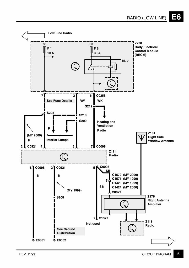
RADIO (LOW LINE) E6
5CIRCUIT DIAGRAMREV: 11/99
See GroundDistribution
S209
B
4 6 7 C0098
S210
S212
Z111Radio
S205
See Fuse Details
6 C025827
30F 110 A
RW WK
P
30F 830 A
Z238Body ElectricalControl Module(BECM)
Low Line Radio
RL 7
S208
Interior Lamps
Heating andVentilation
2 C0921
B
E0361
8 C0098 5 C0098
7 C1377
5 C1571
E0562
Z181Right SideWindow Antenna
Z178Right AntennaAmplifier
Z111Radio
SB
SB
Not used
C1423
C0022
2
(MY 2000)
Radio
(MY 1999)
C0921
C1424
C1570 (MY 2000)(MY 1999)(MY 1999)(MY 2000)
P

RADIO (MID LINE)E6
6 CIRCUIT DIAGRAM REV: 11/99
56
2
YB Y
1
Z111Radio
2 1C1383LC1364
78
4
GB G
3C1374C1378
2 1 C1386LC1360
1 C0688L
2 C0688LK202Left FrontBass Speaker
1 C0726L
2 C0726LK209Left Rear BassSpeaker
S751L
S752L
1 C0455L
2 C0455LK211Left RearMidrangeSpeaker
G
Z239Left RearMidrange FilterCapacitor
GB
GB
C0092
2 C1577L
1 C1577LK200Left FrontMidrangeSpeaker
Z247Left FrontMidrangeFilterCapacitor
YB
1 C0530L
2 C0530L
K197Left FrontTweeter
2.2 µF
2.2 µF2.2 µF
Mid Line Radio
C1366(MY 1999)(MY 2000)
C1379L (MY 2000)(MY 1999)

RADIO (MID LINE) E6
7CIRCUIT DIAGRAMREV: 11/99
34
2
RB R
1
Z111Radio
2 1C1383RC1373
12
4
UB U
3
2 1C1368RC1369
1 C0688R
2 C0688RK203Right FrontBassSpeaker
1 C0726R
2 C0726RK210Right RearBass Speaker
S751R
S752R
1 C0455R
2 C0455RK212Right RearMidrangeSpeaker
G
Z240Right RearMidrange FilterCapacitor
GB
GB
C0092
2 C1577R
1 C1577RK201Right FrontMidrangeSpeaker
Z248Right FrontMidrangeFilterCapacitor
YB
1 C0530R
2 C0530RK198Right FrontTweeter
RB RUB U
YB Y GB
G
2.2 µF
2.2 µF
2.2 µF
Mid Line Radio
C1568(MY 1999)(MY 2000)
C1379L (MY 2000)(MY 1999)
C1423C1571C1570
(MY 1999)(MY 2000)
C1424 (MY 2000)(MY 1999)
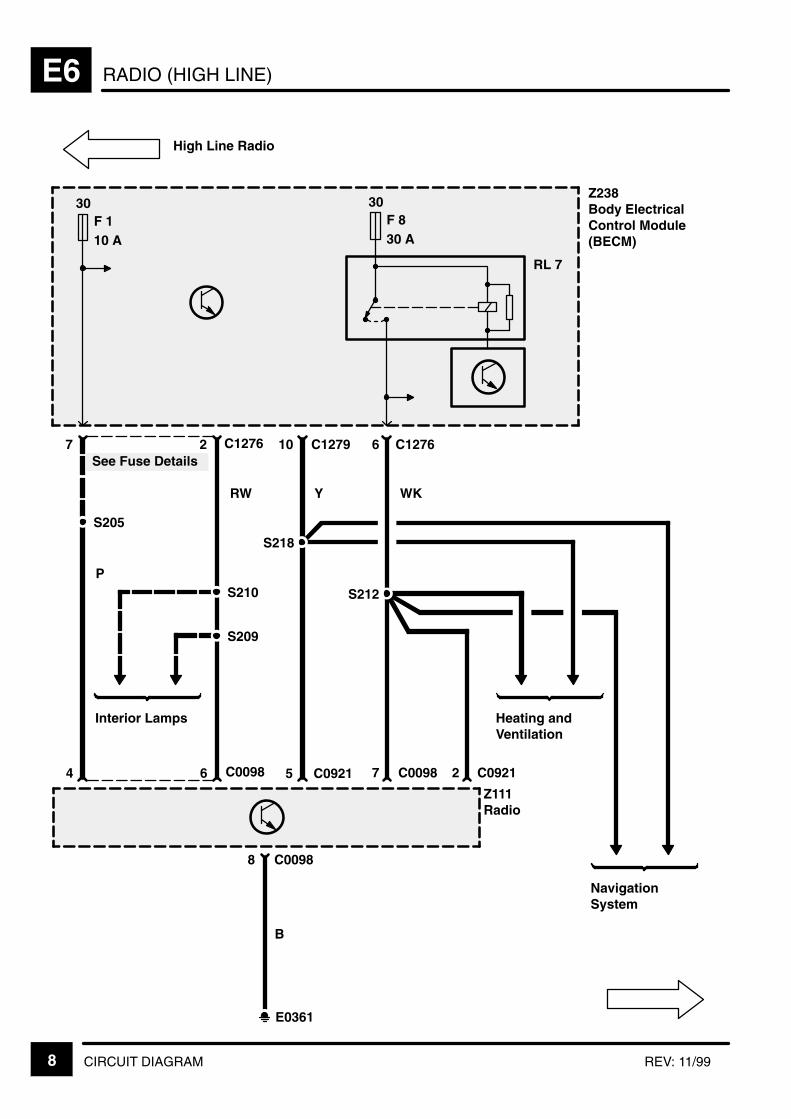
RADIO (HIGH LINE)E6
CIRCUIT DIAGRAM8 REV: 11/99
S209
4 6
S210
Z111Radio
S205
See Fuse Details27
30F 110 A
RW
P
Z238Body ElectricalControl Module(BECM)
30F 830 A
C1276
Interior Lamps
High Line Radio
8 C0098
E0361
7 C0098
Heating andVentilation
WK
S212
B
6
RL 7
C1276 C127910
5 C0921
S218
C0098
Y
NavigationSystem
2 C0921
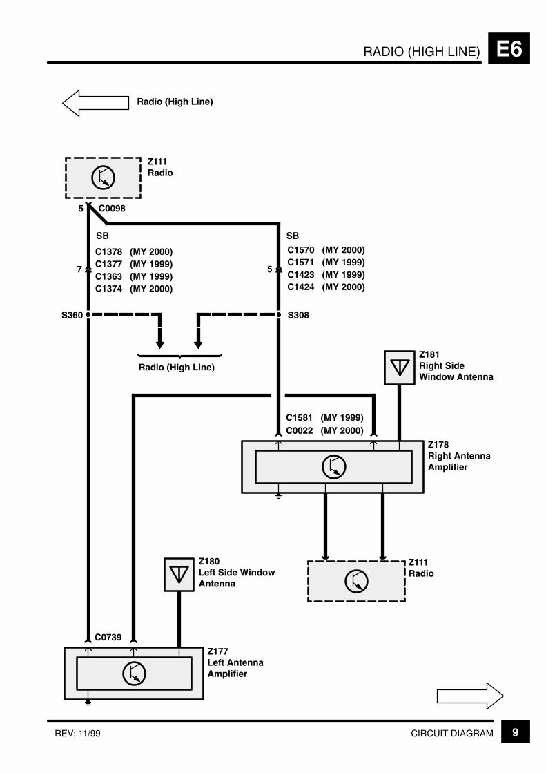
RADIO (HIGH LINE) E6
9CIRCUIT DIAGRAMREV: 11/99
Radio (High Line)
Z111Radio
5 C0098
C0739
7 C1377
Z111Radio
SB
C1363
Z180Left Side WindowAntenna
Z177Left AntennaAmplifier
C0022
Z178Right AntennaAmplifier
Z181Right SideWindow Antenna
S360
5
SB
S308
Radio (High Line)
C1378(MY 1999)(MY 2000)
C1374(MY 1999)(MY 2000)
C1571C1423
C1570(MY 1999)(MY 2000)
C1424(MY 1999)(MY 2000)
C1581(MY 2000)(MY 1999)
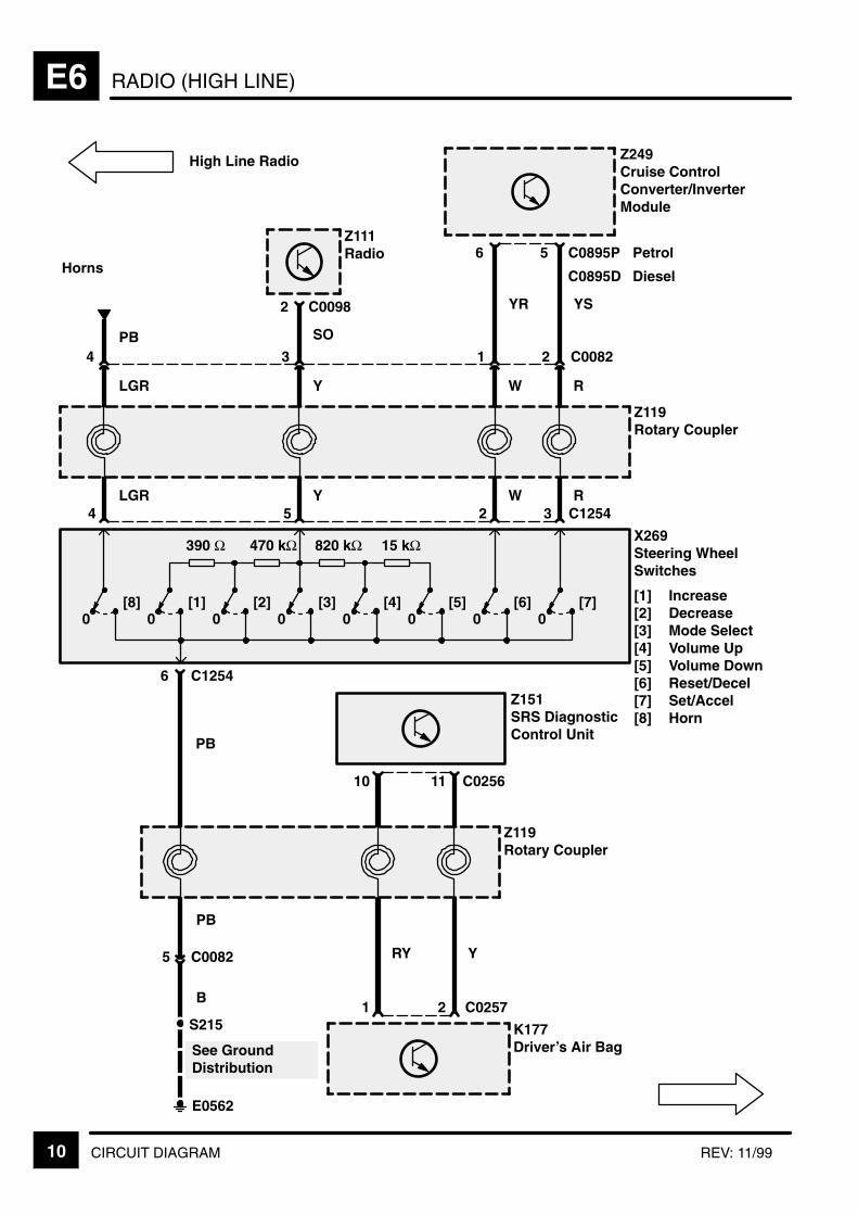
RADIO (HIGH LINE)E6
10 CIRCUIT DIAGRAM REV: 11/99
B
S215
E0562
See GroundDistribution
5 C0082
PB
2
Y
C02571
RY
K177Driver’s Air Bag
Z119Rotary Coupler
Z151SRS DiagnosticControl Unit
11 C025610
X269Steering WheelSwitches
[1] Increase[2] Decrease[3] Mode Select[4] Volume Up[5] Volume Down[6] Reset/Decel[7] Set/Accel[8] Horn
6 C1254
PB
[8]0
[1]0
[2]0
[3]0
[4]0
[5]0
[6]0
[7]0
390 Ω 470 kΩ 820 kΩ 15 kΩ
Z119Rotary Coupler
4 2 3 C1254LGR W R
2 C0082
5Y
134
LGR W RY
Horns
Z249Cruise Control Converter/InverterModule
5 C0895P6Z111Radio
2 C0098
C0895D
Petrol
Diesel
YR YS
PB SO
High Line Radio
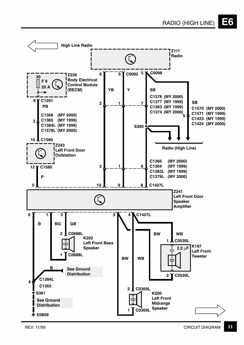
RADIO (HIGH LINE) E6
11CIRCUIT DIAGRAMREV: 11/99
(MY 1999)
56
Z111Radio
5
1 C0688L
2 C0688LK202Left Front BassSpeaker
2 C0530L
1 C0530LK197Left FrontTweeter
1
Z241Left Front DoorSpeakerAmplifier
2 4 C1427L
4C1365
C1384L
B
1 C0369L
2 C0369LK200Left FrontMidrangeSpeaker
36
GB
WB
WBBW
S361
E0809
See GroundDistribution
5
12 C1580
10 C1580Z243Left Front DoorOutstation
P
3C1384LC1365
8
SB
C1427L10
YB
9
Y
8 C1291
Z238Body ElectricalControl Module(BECM)
30F 920 A
PB
2 1 6
2 1 7
C0098
S360
SB
5
Radio (High Line)
C0092
2.2 µF
High Line Radio
BG
BW
B See GroundDistribution
C1368(MY 1999)(MY 2000)
C1578L(MY 1999)(MY 2000)
C1363C1377C1378
(MY 1999)(MY 2000)
C1374 (MY 2000)
(MY 1999)C1423C1571C1570
(MY 1999)(MY 2000)
C1424 (MY 2000)
(MY 1999)C1383LC1364C1366
(MY 1999)(MY 2000)
C1379L (MY 2000)

RADIO (HIGH LINE)E6
12 CIRCUIT DIAGRAM REV: 11/99
34
Z111Radio
5
1 C0688R
2 C0688RK203Right FrontBass Speaker
2 C0530R
1 C0530RK198Right FrontTweeter
1
Z242Right Front DoorSpeakerAmplifier
2 4 C1427R
4C1372
C1384R
B
1 C0369R
2 C0369RK201Right FrontMidrangeSpeaker
36GB
WB
WBBW
S361
E0807
See GroundDistribution
5
12 C1406
10 C1406Z244Right FrontDoor Outstation
P
3C1384RC1372
8
SB
C1427R10
RB
9
R
2 C1284
Z238Body ElectricalControl Module(BECM)
30F 920 A
PB
2 1 6
2 1 5
C0098C0092
YB Y
8
SB
7
Radio (High Line)
C0492R
5C1387RC1371
Z246Right Rear DoorSpeakerAmplifier
2.2 µF
High Line Radio
RB R
BG
BW
See GroundDistribution
B
S308C1586 (MY 2000)
(MY 1999)
C1583
C1578R
(MY 1999)(MY 2000)
(MY 1999)(MY 2000)
C1423C1571C1570
C1424
(MY 1999)(MY 2000)
(MY 1999)(MY 2000)
C1363C1377C1378
C1374
(MY 1999)(MY 2000)
(MY 1999)(MY 2000)
C1383RC1373C1568
C1379R
(MY 1999)(MY 2000)
(MY 1999)(MY 2000)
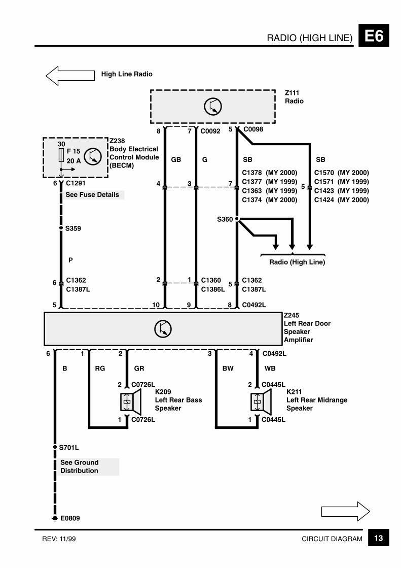
RADIO (HIGH LINE) E6
13CIRCUIT DIAGRAMREV: 11/99
78
Z111Radio
5
1 C0726L
2 C0726LK209Left Rear BassSpeaker
1
Z245Left Rear DoorSpeakerAmplifier
2 4 C0492L
B
1 C0445L
2 C0445LK211Left Rear MidrangeSpeaker
36
RG GR WBBW
S701L
E0809
See GroundDistribution
5
6C1387LC1362
8
SB
C0492L10
GB
9
G
6 C1291
Z238Body ElectricalControl Module(BECM)
30F 1520 A
P
2 15
C1387LC1362
4 3 7C1363C1377
C0098
S360
SB
5
Radio (High Line)
C0092
S359
See Fuse Details
C1386LC1360
High Line Radio
C1378(MY 1999)(MY 2000)
C1374(MY 1999)(MY 2000)
(MY 1999)(MY 2000)
(MY 1999)(MY 2000)
C1423C1571C1570
C1424

RADIO (HIGH LINE)E6
14 CIRCUIT DIAGRAM REV: 11/99
12
Z111Radio
5
1 C0726R
2 C0726RK210Right Rear BassSpeaker
1
Z246Right Rear DoorSpeakerAmplifier
2 4 C0492R
B
1
2K212Right RearMidrange Speaker
36
RG GR WBBW
S701R
E0807
See GroundDistribution
8
6 C1387RC1371
8
SB
C0492R10
UB
9
U
4 C1284
Z238Body ElectricalControl Module(BECM)
30F 1520 A
P
2 1
5
4 3 5
C0098
SB
7
Radio (High Line)
C0092
C1386RC1369
C1427R
6
UB U
5
Z242Right Front DoorSpeakerAmplifier
GB G
High Line Radio
C0445R
C0445R
S308C1586 (MY 2000)
(MY 1999)
C1423C1571C1570
(MY 1999)(MY 2000)
C1424(MY 1999)(MY 2000)
C1363C1377C1378
(MY 1999)(MY 2000)
C1374(MY 1999)(MY 2000)
C1387RC1371
C1383RC1373C1568
(MY 1999)(MY 2000)
C1379R(MY 1999)(MY 2000)
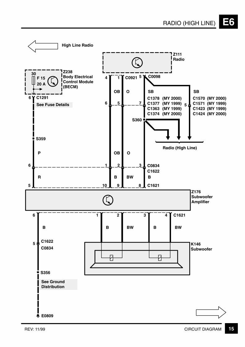
RADIO (HIGH LINE) E6
15CIRCUIT DIAGRAMREV: 11/99
14
Z111Radio
5
Z176SubwooferAmplifier
B
6
S356
E0809
See GroundDistribution
5 8
SB
C162110
OB
9
O6 C1291
Z238Body ElectricalControl Module(BECM)
30F 1520 A
P
1 2 3C1622C0834
6 5 7C1363C1377
C0098
S360
SB
5
Radio (High Line)
C0921
S359
See Fuse Details
6
R B BW B
OB O
5C0834
C1622
B
1
BW
2
B
3
BW
4 C1621
K146Subwoofer
High Line Radio
C1378(MY 1999)(MY 2000)
C1374(MY 1999)(MY 2000)
C1423C1571C1570
(MY 1999)(MY 2000)
C1424(MY 1999)(MY 2000)
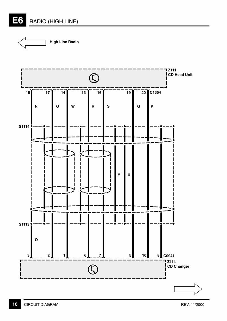
RADIO (HIGH LINE)E6
16 CIRCUIT DIAGRAM REV: 11/2000
17
High Line Radio
Z114CD Changer
14 13 16 19
S1113
S1114
15 20
1 6 7 53 10 8
N O W R S G P
Y U
O
C0941
C1354
Z111CD Head Unit
2
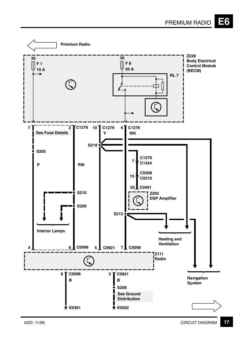
PREMIUM RADIO E6
17CIRCUIT DIAGRAMADD: 11/99
S209
4 6
S210
Z111Radio
S205
See Fuse Details27
30F 110 A
RWP
Z238Body ElectricalControl Module(BECM)
30F 830 A
C1276
Interior Lamps
Premium Radio
8 C0098
E0361
7 C0098
Heating andVentilation
WK
S212
B
6
RL 7
C1276 C127910
5 C0921
S218
C0098
Y
NavigationSystem
2 C0921
B
E0562
S208
See GroundDistribution
15 C0310
C049120
C0308
7 C1424C1570
Z293DSP Amplifier

PREMIUM RADIOE6
18 CIRCUIT DIAGRAM ADD: 11/99
Premium Radio
C1276
Z238Body ElectricalControl Module(BECM)
30F 110 A
S205
See Fuse Details
C1291
30F 15
S362
See Fuse Details
C0834
E1351
7
P
N
C1378C1374
10 P
15 C04915
Z293DSP Amplifier
26 6 14 C0491
B O OB
1 2 C08344
Z176SubwooferAmplifier
5
B
7
P
20 A
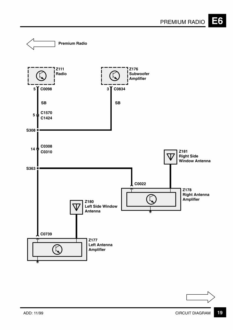
PREMIUM RADIO E6
19CIRCUIT DIAGRAMADD: 11/99
Premium Radio
Z111Radio
5 C0098
C0739
5 C1570
SB
C1424
Z180Left Side WindowAntenna
Z177Left AntennaAmplifier
C0022
Z178Right AntennaAmplifier
Z181Right SideWindow Antenna
S363
14C0308
S308
Z176SubwooferAmplifier
3 C0834
SB
C0310

PREMIUM RADIOE6
20 CIRCUIT DIAGRAM ADD: 11/99
B
S215
E0562
See GroundDistribution
5 C0082
PB
2
Y
C02571
RY
K177Driver’s Air Bag
Z119Rotary Coupler
Z151SRS DiagnosticControl Unit
11 C025610
X269Steering WheelSwitches
[1] Increase[2] Decrease[3] Mode Select[4] Volume Up[5] Volume Down[6] Reset/Decel[7] Set/Accel[8] Horn
6 C1254
PB
[8]0
[1]0
[2]0
[3]0
[4]0
[5]0
[6]0
[7]0
390 Ω 470 kΩ 820 kΩ 15 kΩ
Z119Rotary Coupler
4 2 3 C1254LGR W R
2 C0082
5Y
134
LGR W RY
Horns
Z249Cruise ControlConverter/InverterModule
5 C0895P6Z111Radio
2 C0098
C0895D
Petrol
Diesel
YR YS
PB SO
Premium Radio
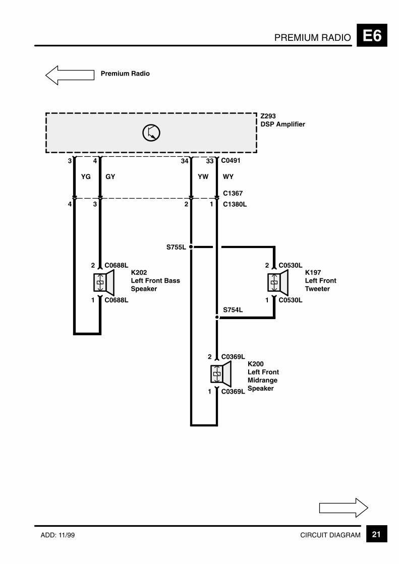
PREMIUM RADIO E6
21CIRCUIT DIAGRAMADD: 11/99
Premium Radio
Z293DSP Amplifier
43
4
YG
3
1 C0688L
2 C0688LK202Left Front BassSpeaker
3334
YW
1 C0369L
2 C0369LK200Left FrontMidrangeSpeaker
C1367
C1380L
C0491
S755L
S754L1 C0530L
2 C0530LK197Left FrontTweeter
GY WY
2 1

PREMIUM RADIOE6
22 CIRCUIT DIAGRAM ADD: 11/99
Premium Radio
Z293DSP Amplifier
2524
4
BG
3
1 C0688R
2 C0688RK203Right FrontBass Speaker
1112
6
BW
5
1 C0369R
2 C0369RK201Right FrontMidrangeSpeaker
C0310
C0308
C0491
S755R
S754R1 C0530R
2 C0530RK198Right FrontTweeter
GB WB
4 3 2 1
C1369
C1380R
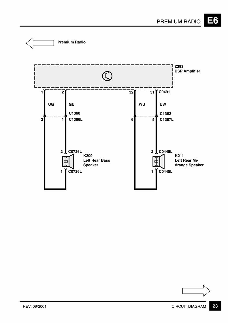
PREMIUM RADIO E6
23CIRCUIT DIAGRAMREV: 09/2001
Premium Radio
Z293DSP Amplifier
21
2
UG
1
1 C0726L
2 C0726LK209Left Rear BassSpeaker
3132
6
WU
5
1 C0445L
2 C0445LK211Left Rear Mi-drange Speaker
C1362
C1387L
C0491
GU UW
C1360
C1386L
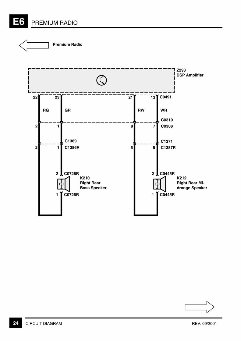
PREMIUM RADIOE6
24 CIRCUIT DIAGRAM REV: 09/2001
Premium Radio
Z293DSP Amplifier
2322
2
RG
1
1 C0726R
2 C0726RK210Right RearBass Speaker
1321
8 7
1 C0445R
2 C0445RK212Right Rear Mi-drange Speaker
C0310
C0308
C0491
GR
2 1 6 5
C1371
C1387R
C1369
C1386R
RW WR
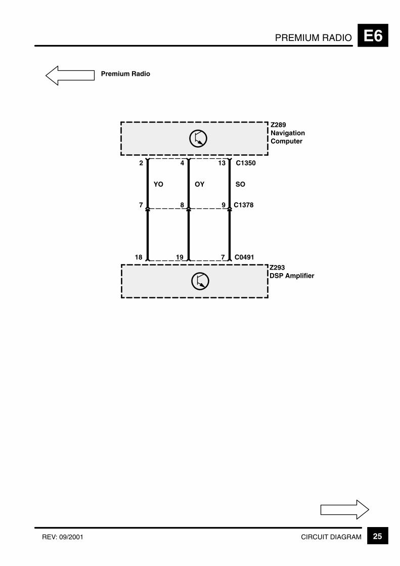
PREMIUM RADIO E6
25CIRCUIT DIAGRAMREV: 09/2001
42
Z289NavigationComputer
13
Z293DSP Amplifier
7
SO
C049118
YO
19
OY
7 8 9 C1378
C1350
Premium Radio

PREMIUM RADIOE6
26 CIRCUIT DIAGRAM ADD: 11/99
5
Z111Radio
6
Z293DSP Amplifier
30
YB
C049138
Y
1 2 C1374
C0092
Premium Radio
3 4
17
RB
9
R
1 2 C1570
10
27
C0922
KB
C1424
9 10C0308C0310
C1378
NAVIGATION SYSTEM E9
CIRCUIT OPERATION 1REV: 09/2001
CIRCUIT OPERATION
The following components make up the navigationsystem:
Navigation Computer (Z289)
GPS Antenna (Z292)
Display and Control Unit (Z291)
Navigation Computer (Z289):
The Navigation Computer (Z289) is located in theright hand side of the luggage compartment,attached to a bracket. The Navigation Computer(Z289) is the main component in the navigationsystem and receives input from the BECM (Z238)and the GPS Antenna (Z292). The NavigationComputer (Z289) contains a solid state piezo gyrowhich measures the motion in the vehicle around itsvertical axis. The gyro operates on the principleknown as the Coriolis force (Refer to the workshopmanual for detailed operation).
Using the inputs from the BECM (Z238), the GPSAntenna (Z292) and the gyro sensor, the NavigationComputer (Z289) can determine the vehicle‘s currentposition, direction and speed.
The Navigation Computer (Z289) also houses theCD–ROM drive. This drive is used to read map datafrom country specific CD’s and also to load updatedsoftware into the computer.
NAVIGATION SYSTEME9
CIRCUIT OPERATION2 REV: 09/2001
GPS Antenna (Z292)
The GPS Antenna (Z292) is located underneath theair intake plenum and is connected to the NavigationComputer (Z289) via a single co–axial cable andpasses signals received from the GPS satellites tothe Navigation Computer (Z289) for processing.
It is possible for the antenna to lose the signals fromthe satellites in hilly or tree lined areas, built upareas with tall buildings, multi–storey car parks,garages, tunnels, bridges and during heavyrain/thunderstorms. When the signal is lost, thenavigation computer will continue to give guidanceusing memory mapped data from the CD map untilthe signal is restored.
Display and Control Unit (Z291)
The Display and Control Unit (Z291) is located in thecentre of the fascia. The unit comprises of a colourLiquid Crystal Display (LCD) screen and controls tooperate the navigation functions. The Display andControl Unit (Z291) comprises four control switches,one rotary press menu control and one status LED.A photosensor is used to control the brightness ofthe screen in day and night time conditions (Refer tothe workshop manual for detailed operation).
Diagnostics Mode
The navigation system may be put into a on–boarddiagnostics mode (service mode) by selecting the’settings’ menu from the main menu then pushingand holding the menu key for about 10 seconds. Theservice mode has four main functions:
1. To check that components are fitted and to determine their hardware/software levels.
2. To perform a quick ’health check’ of the major input signals to the system.
3. To check for correct operation of the display and control unit keys.
4. To check the status of the GPS reception.
Selecting the on–board monitor item from the servicemode menu causes the version info to be displayed.The screen displays the software and hardware levelof the display and control unit together with thediagnostics and bus index. The supplier of the unit isalso displayed as a number code defined by BMW.The system queries the display and control unitbefore displaying the information on the screen. Ifthe unit responds with
Software Hardware levels this implies that thecomponent is connecting to at least power, groundand K–bus.
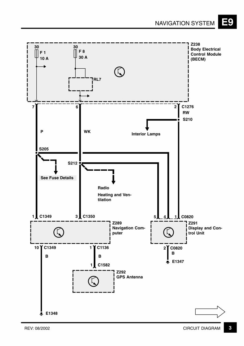
NAVIGATION SYSTEM E9
3CIRCUIT DIAGRAMREV: 08/2002
S212
Z238Body ElectricalControl Module(BECM)
7
30F 110 A
S205
6
1 C1582
E1348
E1347
2 C1276RW
WK Interior Lamps
S210
1 C1349 3 C1350
Z289Navigation Com-puter
10 C1349
B
Z292GPS Antenna
5 4 1 C0820
Z291Display and Con-trol Unit
Radio
B2 C0820
Heating and Ven-tilation
See Fuse Details
P
1 C1136
B
30F 830 A
RL7
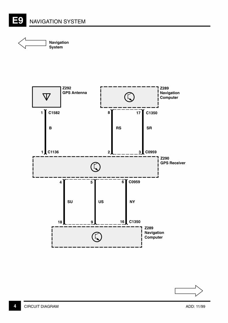
NAVIGATION SYSTEME9
4 CIRCUIT DIAGRAM ADD: 11/99
2
Z290GPS Receiver
6 C0959
3
NavigationSystem
Z289NavigationComputer
Z289NavigationComputer
17 C13508
RS SR
C0959
4 5
16 C135018 9
SU US NY
1 C1136
Z292GPS Antenna
1 C1582
B
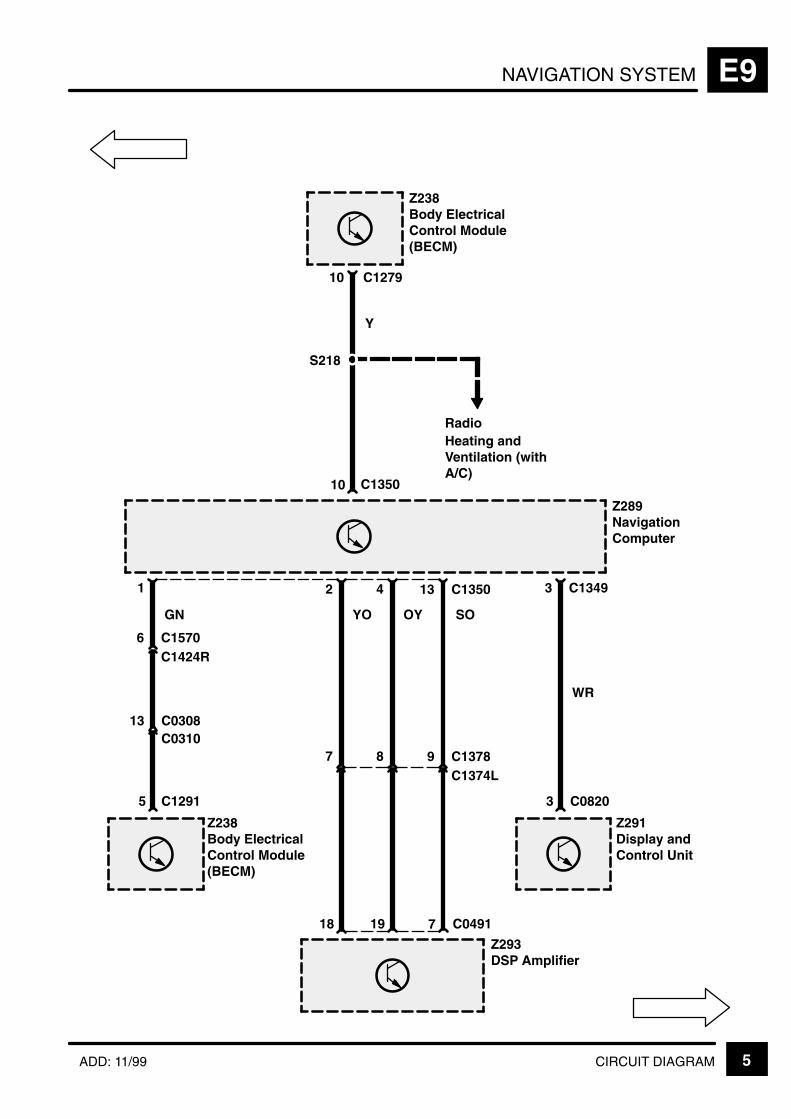
NAVIGATION SYSTEM E9
5CIRCUIT DIAGRAMADD: 11/99
OY
Z289NavigationComputer
3 C1349
10
Z238Body ElectricalControl Module(BECM)
Z291Display andControl Unit
10 C1279
Y
C1350
2 4
3 C0820
18 19
YO
WR
13
7
C1350
7 8 9 C1378C1374L
1
5 C1291
GN
6 C1570C1424R
S218
Radio
SO
C0491
13 C0308C0310
Z238Body ElectricalControl Module(BECM)
Z293DSP Amplifier
Heating andVentilation (withA/C)
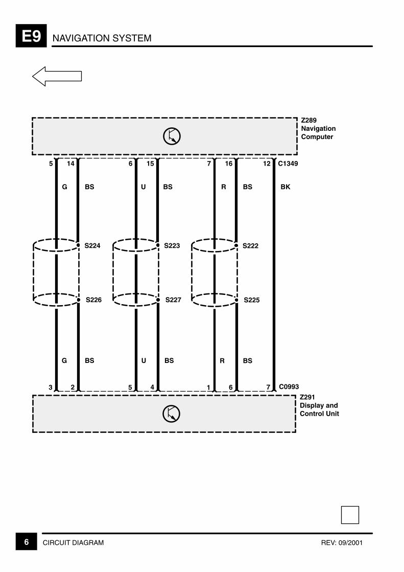
NAVIGATION SYSTEME9
6 CIRCUIT DIAGRAM REV: 09/2001
BSBS
Z289NavigationComputer
5
G
3
S224
14
2
12 C1349
7 C0993
Z291Display andControl Unit
S226
BS BK
G BS
6
5
S223
15
4
S227
U BS
7
R
1
S222
16
6
S225
R BS
U
WASH/WIPE F5
CIRCUIT OPERATION 1
CIRCUIT OPERATION
Front Wipers
The front wipers will only operate with auxiliary orignition on, except when auxiliary and ignition areboth turned off, the wipers will continue to operateuntil they reach the park position. If the engine iscranked while the wipers are on, then the wiperoperation will be suspended until cranking isreleased.
Flick Wipe Operation
When the flick wipe switch is operated, the wiper willoperate in the slow wipe mode until the switch isreleased.
Intermittent Operation
When the wiper control stalk is moved to theintermittent position, the wipers will perform one wipeof the screen at slow speed and then wait for Nseconds before doing another wipe etc. The value ofN is determined by the position of the wipe delaypotentiometer. When the potentiometer is in the farleft position the time delay is 2 seconds. Eachmovement of the potentiometer to the right doublesthe time delay, up to a maximum of 32 seconds.
Slow Speed Operation
When the wiper control stalk is moved to the slowposition, the wipers will operate continuously at slowspeed.
Fast Speed Operation
When the wiper control stalk is moved to the fastposition, the wipers will start operating at fast speedimmediately and will continue to do so until fastspeed is switched off.
Front Screen Programmed Wash/Wipe
If the wash/wipe switch is operated, the front screenwash motor will operate for 1.5 seconds or for theduration the switch is held on, whichever is thelonger.
The slow front wipe will be operated for 0.5 secondsafter the switch is closed and will continue to operateuntil three full wipes have been completed after thewash motor has ceased it’s operation.
Rear Wiper
Intermittent Operation
When the rear wiper stalk is moved to the “on”position, then the rear wiper will perform twocomplete wipes and stop in the park position. After
that, its operation will vary depending on theselected mode of the front wipers.
Reverse Gear Wiping
If reverse gear is selected while auxiliary or ignitionis on and a front wiper function is selected, then therear wiper will operate as well.
If reverse gear is selected while the front wipers areoff (or performing a wash/wipe cycle) then the rearwiper will operate in the mode indicated by the rearwiper switch.
Rear Screen Programmed Wash/Wipe
If the rear wash/wipe switch is operated, the rearscreen wash motor will operate for 1.5 seconds orfor as long as the switch is held on, whichever is thelonger. The rear wipe will be operated 0.5 secondsafter the switch closed and will continue to operateuntil three full wipes have been completed after thewasher motor has ceased it’s operation.
Wiper Operation With Speed Dependency On
If the vehicle has speed dependent wipers, the wiperadapts its speed to the vehicle speed.
The speed barrier, where the wipers move betweena faster or slower operation, is 2 mph.
Headlight Wash/Wipe
If the headlight switch is in the on position, the firstand every alternate operation of the front screenwash switch will activate the headlight wash/wipemotor, which will operate for 2 seconds, regardlessof the length of time the switch is pressed.
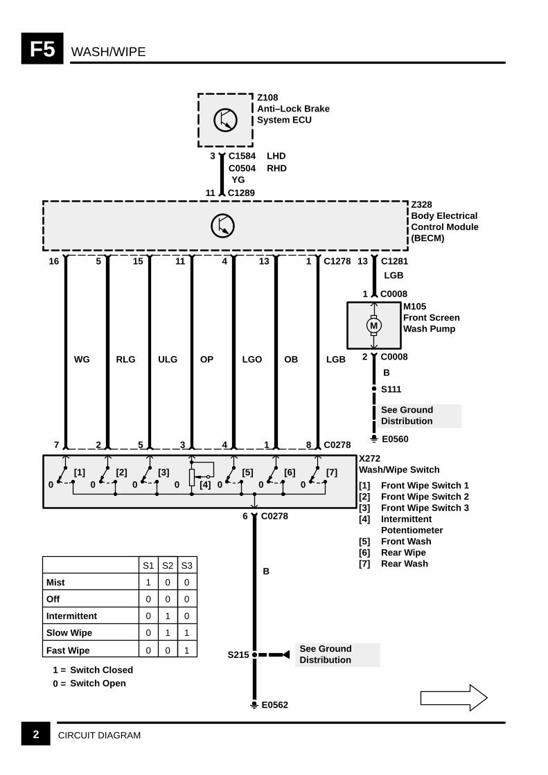
WASH/WIPEF5
2 CIRCUIT DIAGRAM
Z328Body ElectricalControl Module(BECM)
13 C1281
LGB
16
WG
5
RLG
15
ULG
11
OP
4
LGO
13
OB
1
LGB
C1278
X272Wash/Wipe Switch
[1] Front Wipe Switch 1[2] Front Wipe Switch 2[3] Front Wipe Switch 3[4] Intermittent
Potentiometer[5] Front Wash[6] Rear Wipe[7] Rear Wash
1 C0008
2 C0008
M
S111
See GroundDistribution
E0560
B
M105Front ScreenWash Pump
3 C1584
YG11 C1289
Z108Anti–Lock BrakeSystem ECU
C0504LHDRHD
1 =
0 =
Switch ClosedSwitch Open
Fast Wipe
Mist
Off
Intermittent
Slow Wipe
S1 S2 S3
1 0 0
0 0 0
0 1 0
0 1 1
0 0 1
7
0[1]
2 5 3 4 1 8 C0278
6 C0278
B
E0562
S215
0[2]
0[3]
0 [4] 0[5]
0[6]
0[7]
See GroundDistribution
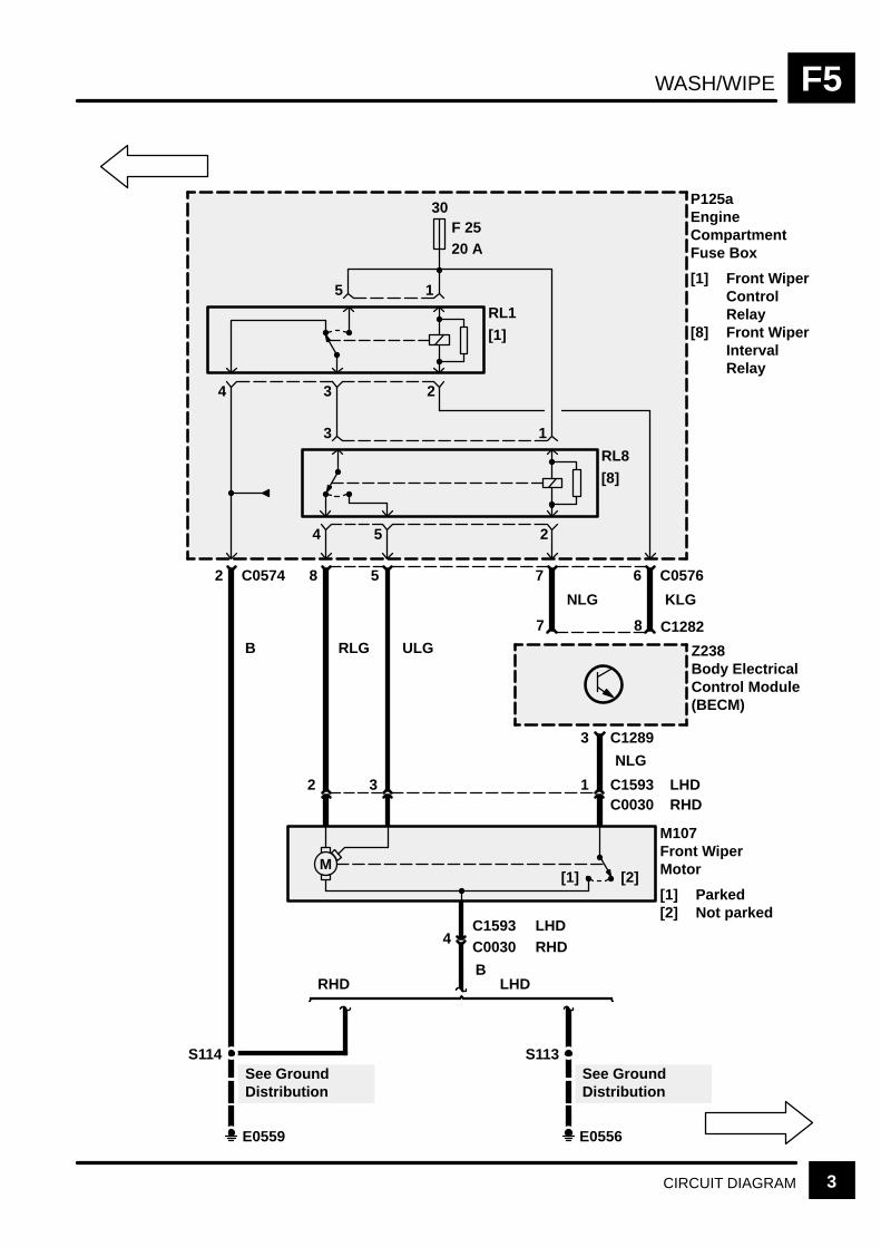
WASH/WIPE F5
3CIRCUIT DIAGRAM
30F 2520 A
RL1
[1]
23
15
6 C0576
4
RL8
[8]
25
13
4
7582 C0574
P125aEngineCompartmentFuse Box
[1] Front WiperControlRelay
[8] Front WiperIntervalRelay
8 C1282
Z238Body ElectricalControl Module(BECM)
7
3 C1289
KLGNLG
NLG
1C0030C159332
M[2][1]
M107Front WiperMotor
[1] Parked[2] Not parked
4 C0030C1593 LHD
RHD
LHDRHD
B
ULGRLGB
S113
E0556
See GroundDistribution
S114
E0559
See GroundDistribution
LHDRHD

WASH/WIPEF5
4 CIRCUIT DIAGRAM REV: 08/2002
30F 2520 A
RL11
[11]
23
15
5 C0571
4
5412 C0574
P125aEngine Compart-ment Fuse Box
[11] HeadlampsWash/WipeRelay
LGRNULGULGUB
S101
E0557
See Ground Dis-tribution
S111
E0560
See Ground Dis-tribution
4
6 C1282
M
1 C0874
2 C0874M
[1][2]
4 C0853
1 C0853
M
[1][2]
3 C0854
2
R
B
4
B B
2
1 C0854
S114
E0559
See Ground Dis-tribution
Z238Body ElectricalControl Module(BECM)
M110Headlamp WashPump
C0576 C0570
M157Right HeadlampWiper Motor
[1] Run[2] Park
M156Left HeadlampWiper Motor
[1] Run[2] Park
3 C1278
U
4 C0041
3 C0041B
X145Main LightingSwitch
[2] Headlamps
E0562
See Ground Dis-tribution
S208
[2]
0
YBRB
B
YBRB
W

WASH/WIPE F5
5CIRCUIT DIAGRAMREV: 11/99
30F 1520 A
RL8
S111
E0560
See GroundDistribution
M
1 C0021
2 C0021
M[1][2]
4 C1281
BLG
B
M119Rear ScreenWash Pump
1 C12857 C1283
OPOBB
E0808
B
2 C0607C0494
1
3 C03882
M120Rear Wiper Motor
[1] Parked[2] Not Parked
S851
E0565
1 C0388
B
Z238Body ElectricalControl Module(BECM)
See GroundDistribution
See GroundDistribution
C1356C1584 (MY 2000)
(MY 1999)C1584 (MY 2000)
(MY 1999)

WASH/WIPEF5
6 CIRCUIT DIAGRAM REV: 08/99
8
Z238Body ElectricalControl Module(BECM)
2 C0167
9 18 C1287
AutomaticTransmission
ManualTransmission
13 C0746
0
X157Reverse Switch
S551
E1355
UP UG
S608
S609
S610
UB
6 C0244
0 [1]
X
1
0 [2]
Y
2
0 [3]
Z
3 C0244
GN
B
2 C0988
BS
S607
E0808
C0989
1 C0167
See GroundDistribution
See GroundDistribution
C0745
X294Gear BoxPosition Switch
[1] X Switch[2] Y Switch[3] Z Switch
P 0 1 1R 0 0 1N 1 0 1D 1 0 03 0 0 0
2 0 1 01 1 1 0Z* 1 1 1
X Y Z
GN
UB
ManualTransmission
AutomaticTransmission
AutomaticGearbox
1 =
0 =
* =
Switch Open
Switch Closed
Fault
5C0745
43 C0988
1
7 C0989C0746

HEATED FRONT SCREEN F6
CIRCUIT OPERATION 1
CIRCUIT OPERATION
This operates only with the engine running, which isdetermined by the HEVAC panel. In the off state, thesignal is at 12 volts. When the Heated FrontWindscreen is activated, the signal is switched to 0volts. This provides the ground required for relay 5 tobe pulled in, as there is an ignition feed on the otherside of the coil provided by relay 15. This relayenergises one half of the heated screen elements.
Once relay 5 has been energised, a 12 volt signal isprovided to the coil of relay 4. The other side of thecoil is connected directly to ground, therebyenergising the relay and switching on the other halfof the elements.
There is also a feed spliced from the harness whichprovides the petrol Engine Control Module with asignal that tells the unit there will be a large electricalload turned on/off.
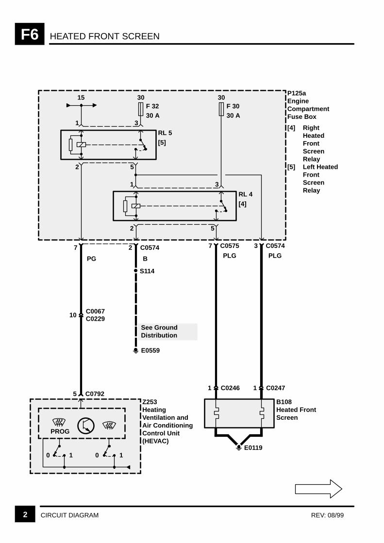
HEATED FRONT SCREENF6
2 CIRCUIT DIAGRAM REV: 08/99
30F 3230 A
P125aEngineCompartmentFuse Box
[4] RightHeatedFrontScreenRelay
[5] Left HeatedFrontScreenRelay
RL 5
[5]
7
PG
Z253HeatingVentilation andAir ConditioningControl Unit(HEVAC)
5 C0792
15
B
S114
E0559
See GroundDistribution
52
31
30F 3030 A
RL 4
[4]
52
31
2 C0574 7 C0575 3 C0574
B108Heated FrontScreen
1 C0247
PLG
1 C0246
PLG
E01190 1 0 1
PROG
10 C0067C0229
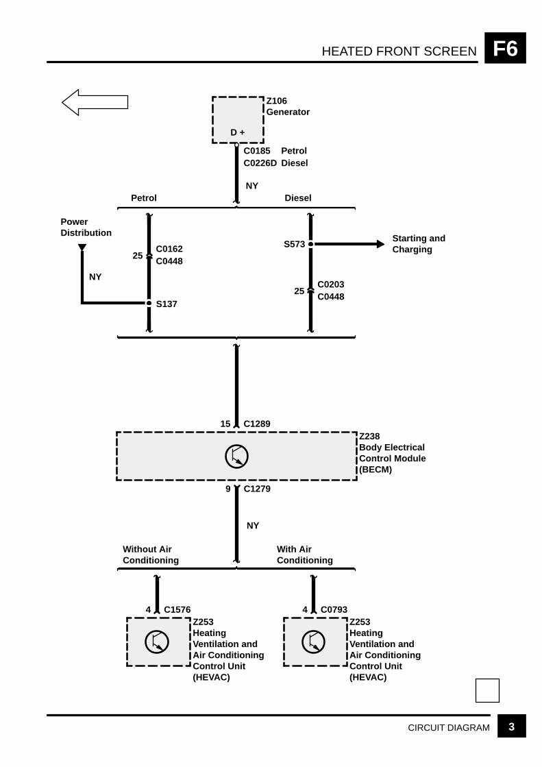
HEATED FRONT SCREEN F6
3CIRCUIT DIAGRAM
25C0448
NY
C0162
25C0448C0203
15 C1289
Petrol Diesel
Z106Generator
Z238Body ElectricalControl Module(BECM)
S573
9 C1279
4 C0793Z253HeatingVentilation andAir ConditioningControl Unit(HEVAC)
Starting andCharging
D +
NY
C1576
With AirConditioning
Without AirConditioning
4Z253HeatingVentilation andAir ConditioningControl Unit(HEVAC)
C0226DC0185 Petrol
Diesel
PowerDistribution
S137
NY

HEATED REAR SCREEN F9
CIRCUIT OPERATION 1
CIRCUIT OPERATION
The rear screen heater will reflect the state of theheated rear screen input from the HEVAC unit at anytime while the BeCM (Z238) is in the active mode.This signal is normally 12V and 0V when active(Active Low).
The HEVAC unit will control all timing functionsrelated to the rear screen heater.

HEATED REAR SCREENF9
2 CIRCUIT DIAGRAM REV: 11/99
Z253HeatingVentilation andAir ConditioningControl Unit(HEVAC)
0 1
B141Rear Screen
2 C1292
30F 1230 A
Z238Body ElectricalControl Module(BECM)
RL 11
11 C1279
1 C0381
B
S851
E0565
See GroundDistribution
2C0609C0496
1 C0382
PLGWB
Without AirConditioning
With AirConditioning
17 C0793
Z253HeatingVentilation andAir ConditioningControl Unit(HEVAC)
9 C1576
15
0 1
C1587(MY 1999)(MY 2000)
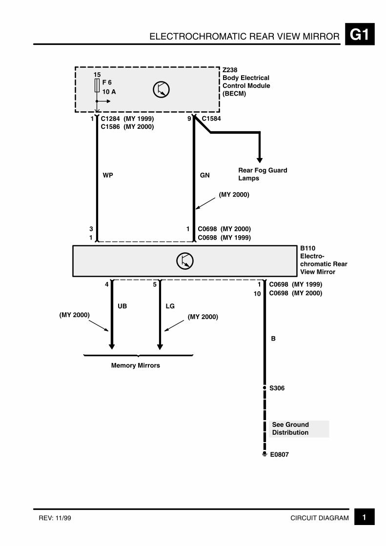
ELECTROCHROMATIC REAR VIEW MIRROR G1
1CIRCUIT DIAGRAMREV: 11/99
Z238Body ElectricalControl Module(BECM)
1
See GroundDistribution
B110Electro-chromatic RearView Mirror
WP
15F 610 A
B
1 C1284 (MY 1999) 9 C1584
1 C0698
1 C06984 5
UB LG
(MY 2000)(MY 2000)
S306
C1586 (MY 2000)
E0807
Rear Fog GuardLampsGN
C0698(MY 2000)(MY 1999)
Memory Mirrors
C0698(MY 1999)(MY 2000)10
3
(MY 2000)
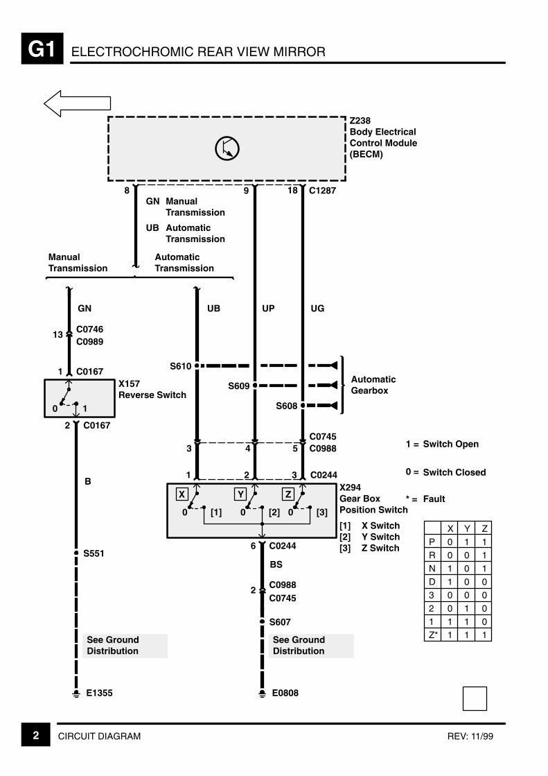
ELECTROCHROMIC REAR VIEW MIRRORG1
2 CIRCUIT DIAGRAM REV: 11/99
8
Z238Body ElectricalControl Module(BECM)
2 C0167
9
AutomaticTransmission
ManualTransmission
13 C0746
0 1
X157Reverse Switch
S551
E1355
UP UG
S608
S609
S610
UB
6 C0244
0 [1]
X
1
0 [2]
Y
2
0 [3]
Z
3 C0244
GN
B
BS
S607
E0808
C0989
1 C0167
See GroundDistribution
See GroundDistribution
X294Gear BoxPosition Switch
[1] X Switch[2] Y Switch[3] Z Switch
P 0 1 1R 0 0 1N 1 0 1
D 1 0 03 0 0 02 0 1 01 1 1 0Z* 1 1 1
X Y Z
GN
UB
ManualTransmission
AutomaticTransmission
AutomaticGearbox
1 =
0 =
* =
Switch Open
Switch Closed
Fault
18 C1287
2 C0988C0745
5C0745
43 C0988
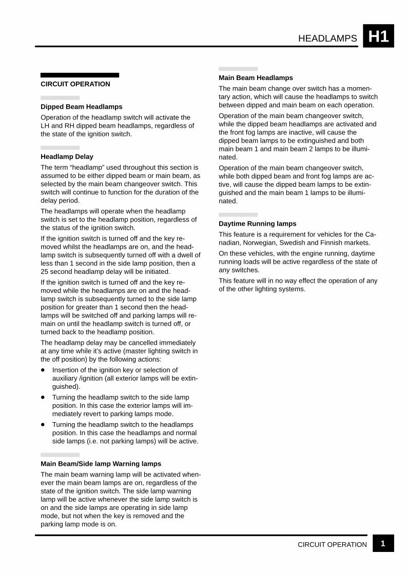
HEADLAMPS H1
CIRCUIT OPERATION 1
CIRCUIT OPERATION
Dipped Beam Headlamps
Operation of the headlamp switch will activate theLH and RH dipped beam headlamps, regardless ofthe state of the ignition switch.
Headlamp Delay
The term “headlamp” used throughout this section isassumed to be either dipped beam or main beam, asselected by the main beam changeover switch. Thisswitch will continue to function for the duration of thedelay period.
The headlamps will operate when the headlampswitch is set to the headlamp position, regardless ofthe status of the ignition switch.
If the ignition switch is turned off and the key re-moved whilst the headlamps are on, and the head-lamp switch is subsequently turned off with a dwell ofless than 1 second in the side lamp position, then a25 second headlamp delay will be initiated.
If the ignition switch is turned off and the key re-moved while the headlamps are on and the head-lamp switch is subsequently turned to the side lampposition for greater than 1 second then the head-lamps will be switched off and parking lamps will re-main on until the headlamp switch is turned off, orturned back to the headlamp position.
The headlamp delay may be cancelled immediatelyat any time while it’s active (master lighting switch inthe off position) by the following actions:
Insertion of the ignition key or selection ofauxiliary /ignition (all exterior lamps will be extin-guished).
Turning the headlamp switch to the side lampposition. In this case the exterior lamps will im-mediately revert to parking lamps mode.
Turning the headlamp switch to the headlampsposition. In this case the headlamps and normalside lamps (i.e. not parking lamps) will be active.
Main Beam/Side lamp Warning lamps
The main beam warning lamp will be activated when-ever the main beam lamps are on, regardless of thestate of the ignition switch. The side lamp warninglamp will be active whenever the side lamp switch ison and the side lamps are operating in side lampmode, but not when the key is removed and theparking lamp mode is on.
Main Beam Headlamps
The main beam change over switch has a momen-tary action, which will cause the headlamps to switchbetween dipped and main beam on each operation.
Operation of the main beam changeover switch,while the dipped beam headlamps are activated andthe front fog lamps are inactive, will cause thedipped beam lamps to be extinguished and bothmain beam 1 and main beam 2 lamps to be illumi-nated.
Operation of the main beam changeover switch,while both dipped beam and front fog lamps are ac-tive, will cause the dipped beam lamps to be extin-guished and the main beam 1 lamps to be illumi-nated.
Daytime Running lamps
This feature is a requirement for vehicles for the Ca-nadian, Norwegian, Swedish and Finnish markets.
On these vehicles, with the engine running, daytimerunning loads will be active regardless of the state ofany switches.
This feature will in no way effect the operation of anyof the other lighting systems.

HEADLAMPSH1
2 CIRCUIT DIAGRAM REV: 08/99
Z238Body ElectricalControl Module(BECM)
S205
30F 110 A
Z142InstrumentCluster[15] Control Unit
and Mess-age CentreDisplay[15]
8 18
14 5
2 12
2 10
3 13
1 9
5 15
11
17 7
Z238Body ElectricalControl Module(BECM)
9 3
1
12 8
X273Direction Indicator[1] Headlamp
Flash[2] Main Beam
C1278
C0041X145Main LightingSwitch[1] Side Lamps[2] Headlamps
S208
4
E0562
1 2 C0036
0 0
[1] [2]0
[2]
0
[1]
S215
E0562
E0564
7 C1276
C1278
C12803
2
3 C00418 C0036
Interior Lamps
BB
OR U UW USRW
B BBG BG RG RG OG OG LG LG
PP
See Fuse Details
See GroundDistribution
See GroundDistribution
4 C023314

HEADLAMPS H1
3CIRCUIT DIAGRAM
See GroundDistribution
See GroundDistribution
Z238Body ElectricalControl Module(BECM)
US
10 8
UG
C1281
1 2 C0009
RB
5 11
UK
5 4
UB
1 5
UP
C1282
1 2 C0011
RW
9 3
UO
5 4
E0560
3 C00116
S111
[1] [2] [3] [4]
B116Left Headlamp[1] Side Lamp[2] Dipped
Beam[3] Main Beam[4] Main Beam
2
E0557
3 C00096
S101
[1] [2] [3] [4]
B130Right Headlamp[1] Side Lamp[2] Dipped Beam[3] Main Beam[4] Main Beam 2
Z238Body ElectricalControl Module(BECM)
13 C1280
4 C0028
X134Ignition Switch
0
I IIIII
S215
E0562
3 C0028
3 C1279
2 C0672
0 [1]
1 C0672
X229Key–In Switch[1] Key Inserted
Except NAS
B B B B
B B
NW WK
See GroundDistribution

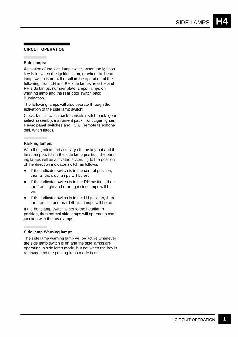
SIDE LAMPS H4
CIRCUIT OPERATION 1
CIRCUIT OPERATION
Side lamps:
Activation of the side lamp switch, when the ignitionkey is in, when the ignition is on, or when the headlamp switch is on, will result in the operation of thefollowing; front LH and RH side lamps, rear LH andRH side lamps, number plate lamps, lamps onwarning lamp and the rear door switch packillumination.
The following lamps will also operate through theactivation of the side lamp switch:
Clock, fascia switch pack, console switch pack, gearselect assembly, instrument pack, front cigar lighter,Hevac panel switches and I.C.E. (remote telephonedial, when fitted).
Parking lamps:
With the ignition and auxiliary off, the key out and theheadlamp switch in the side lamp position, the park-ing lamps will be activated according to the positionof the direction indicator switch as follows:
If the indicator switch is in the central position,then all the side lamps will be on.
If the indicator switch is in the RH position, thenthe front right and rear right side lamps will beon.
If the indicator switch is in the LH position, thenthe front left and rear left side lamps will be on.
If the headlamp switch is set to the headlampposition, then normal side lamps will operate in con-junction with the headlamps.
Side lamp Warning lamps:
The side lamp warning lamp will be active wheneverthe side lamp switch is on and the side lamps areoperating in side lamp mode, but not when the key isremoved and the parking lamp mode is on.
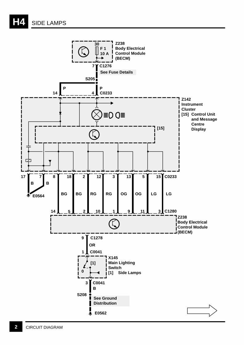
SIDE LAMPSH4
2 CIRCUIT DIAGRAM
Z238Body ElectricalControl Module(BECM)
S205
Z142InstrumentCluster[15] Control Unit
and MessageCentreDisplay[15]
8 18
14 5
2 12
2 10
3 13
1 9
5 15
11
17 7
Z238Body ElectricalControl Module(BECM)
9
X145Main LightingSwitch[1] Side Lamps
C1278
S208
E0562
1 C0041
0
[1]
E0564
7 C1276
C0233
C12803
3 C0041
PP
B B
BG BG RG RG OG OG LG LG
OR
B
30F 110 A
See GroundDistribution
See Fuse Details
4 C023314

SIDE LAMPS H4
3CIRCUIT DIAGRAM
E0557
S101
Z238Body ElectricalControl Module(BECM)
5 C12819 C1282
B115Left Front LampAssembly[1] Direction
IndicatorLamp
[2] Side Lamp1 C0001
[2] [1]
2 C00013
B116Left Headlamp[1] Side Lamp
6 C0009
5 C0009
[1]
NAS Except NAS
E0560
S111
B128Right Front LampAssembly[1] Direction
IndicatorLamp
[2] Side Lamp1 C1345
[2] [1]
2 C13453B130Right Headlamp[1] Side Lamp
6 C0011
5 C0011
[1]
NAS Except NAS
NAS
NAS
DirectionIndicator Lamps
RW
B
B
GR
RB
GW
BB
See GroundDistribution
See GroundDistribution
DirectionIndicator Lamps
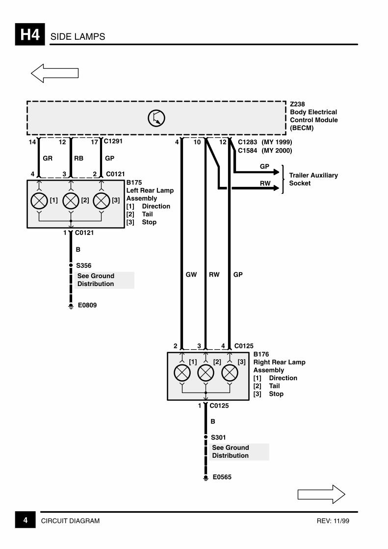
SIDE LAMPSH4
4 CIRCUIT DIAGRAM REV: 11/99
Z238Body ElectricalControl Module(BECM)
RB
12 17
GP
C1291
3 2 C0121
14
GR
4
E0809
C0121
B
1
S356
[1] [2] [3]
B175Left Rear LampAssembly[1] Direction[2] Tail[3] Stop
RW
10 12
GP
C1283
3 4 C0125
4
GW
2
E0565
C0125
B
1
S301
[1] [2] [3]B176Right Rear LampAssembly[1] Direction[2] Tail[3] Stop
GP
RWTrailer AuxiliarySocket
See GroundDistribution
See GroundDistribution
C1584(MY 1999)(MY 2000)
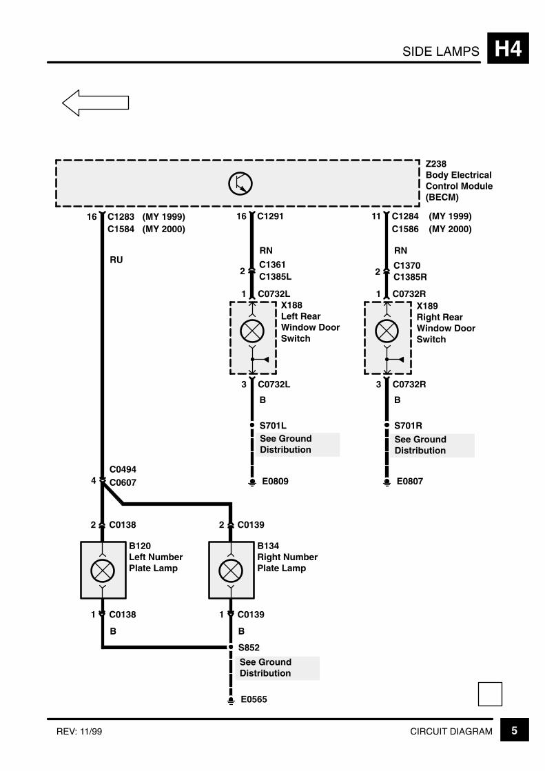
SIDE LAMPS H4
5CIRCUIT DIAGRAMREV: 11/99
Z238Body ElectricalControl Module(BECM)
E0565
S852
B134Right NumberPlate Lamp
B
E0807
S701R
C1284
X189Right RearWindow DoorSwitch
3 C0732R
1 C0732R
B
2C1370C1385R
11
RN
E0809
S701L
C1291
X188Left RearWindow DoorSwitch
3 C0732L
1 C0732L
B
2C1361C1385L
16
RN
C128316
RU
1 C0139
2 C0139
4C0494C0607
B120Left NumberPlate Lamp
B
1 C0138
2 C0138
See GroundDistribution
See GroundDistribution
See GroundDistribution
C1584(MY 1999)(MY 2000) C1586
(MY 1999)(MY 2000)

KEY INFORMATIONi
!"
#$ % &'( ' )
*$ % &'( + %
,# % &'( ' )
% &'( ' )
-
*, !+
!
+ ' '
+ .) . . '
/+ +0 .
' /'+0
"% ) '
+ ) . % .
+ +- %
. )
(
.
!"
. ' % 1(
2 + " .
' ) '
2 +' 3 .
.' % '
2 .) % '
2 4 .' % '-
&+
+ )
+ /0 .
+ ' %
STOP LAMPS H5
CIRCUIT OPERATION 1
CIRCUIT OPERATION
Brake lamps
The brake lamps (including the high mounted stoplamp when fitted), are operated when the brakeswitch is closed, provided the ignition is switched on.

STOP LAMPSH5
2 CIRCUIT DIAGRAM REV: 08/2002
Z238Body ElectricalControl Module(BECM)
S205
Z142InstrumentCluster[15] Control
Unit andMessageCentre Dis-play
[15]
BG
8 18
BG
14 5
RG
2 12
RG
2 10
OG
3 13
OG
1 9
LG
5 15
LG
11
B7
B
Z238Body ElectricalControl Module(BECM)
E0564
P P
7 C1276
C0233
C128034 C1276
17
W
9
X168Stop LampSwitch[1] Brake
Pedal De-pressed
S201
1 C0075
0 0[1] [1]
2 C0075
YPGP
3
Anti–Lock BrakeSystem
15F 1710 A
30F 110 A
See Fuse Details
4 C023314
4
A H5-3
GP
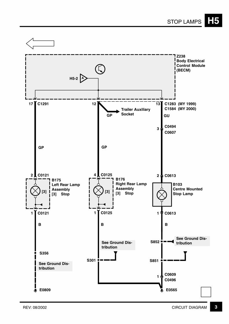
STOP LAMPS H5
3CIRCUIT DIAGRAMREV: 08/2002
See Ground Dis-tribution
Z238Body ElectricalControl Module(BECM)
E0565
B103Centre MountedStop Lamp
B
S356
C1291
B175Left Rear LampAssembly[3] Stop
1 C0121
2 C0121
B
17
GP
1 C0613
2 C0613
GP
S301
B
12
[3]
13 C1283
GU
3C0607
C0494
S851
S852
1C0496C0609
B176Right Rear LampAssembly[3] Stop
1 C0125
4 C0125
GP
[3]
E0809
Trailer AuxiliarySocket
See Ground Dis-tribution
See Ground Dis-tribution
C1584(MY 1999)(MY 2000)
AH5-2

KEY INFORMATIONi
!"
#$ % &'( ' )
*$ % &'( + %
,# % &'( ' )
% &'( ' )
-
*, !+
!
+ ' '
+ .) . . '
/+ +0 .
' /'+0
"% ) '
+ ) . % .
+ +- %
. )
(
.
!"
. ' % 1(
2 + " .
' ) '
2 +' 3 .
.' % '
2 .) % '
2 4 .' % '-
&+
+ )
+ /0 .
+ ' %
DIRECTION INDICATOR LAMPS H6
CIRCUIT OPERATION 1
CIRCUIT OPERATION
Hazard lamps
When the hazard warning switch is operated, allindicator bulbs, side repeaters and the hazard switchillumination bulb will operate at the specified rate,regardless of the ignition switch position. Theindicator warning lamps within the instrument packwill also operate under this condition.
If the inertia switch is operated and the ignition is on,all indicator bulbs, side repeaters, warning lampsand the hazard switch bulb will flash at the specifiedrate.
In addition to the operation of the indicator bulbsthere will be an audible tick generated by the BeCM,timed to match the bulb illumination in the instrumentpack.
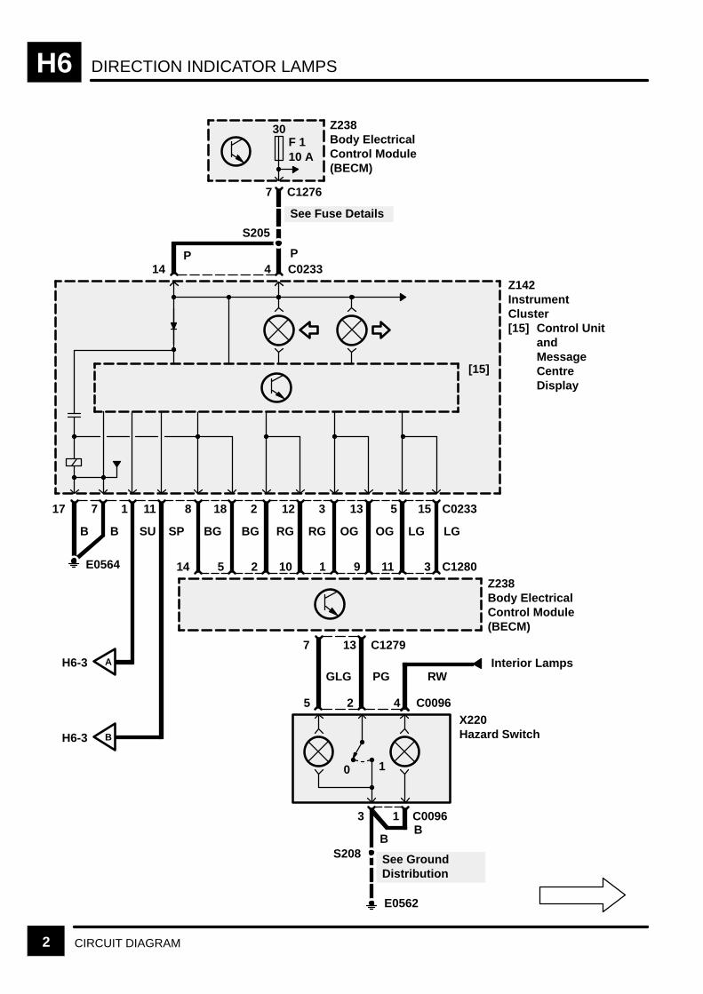
DIRECTION INDICATOR LAMPSH6
2 CIRCUIT DIAGRAM
S205
[15]
BG
8 18
BG
14 5
RG
2 12
RG
2 10
OG
3 13
OG
1 9
LG
5 15
LG
11
B
17 7
B
5
7 13 C1279
C0096X220Hazard Switch
2
0 1
S208
E0562
E0564
P P
7 C1276
C0233
C12803
4
3B
Z238Body ElectricalControl Module(BECM)
Z142InstrumentCluster[15] Control Unit
andMessageCentreDisplay
Z238Body ElectricalControl Module(BECM)
RWInterior Lamps
C00961
1
SU
11
SP
H6-3 A
H6-3 B
30F 110 A
GLG PG
B
See GroundDistribution
See Fuse Details
4 C023314
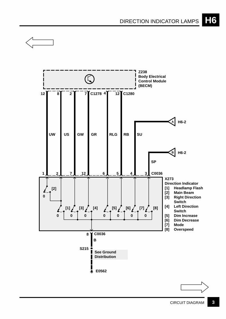
DIRECTION INDICATOR LAMPS H6
3CIRCUIT DIAGRAM
UW
12 8
US
1 2
GW
2 7
GR
7 12
RLG
4 12
RB
6 5
SU
SP
4
8
0
[2]
S215
C1280
C00363
B
Z238Body ElectricalControl Module(BECM)
X273Direction Indicator[1] Headlamp Flash[2] Main Beam[3] Right Direction
Switch[4] Left Direction
Switch[5] Dim Increase[6] Dim Decrease[7] Mode[8] Overspeed
C0036
E0562
H6-2
H6-2
0
[1]
0
[5]
0
[3]
0
[4]
0
[6]
0
[7]
0
[8]
C1278
B
A
See GroundDistribution

DIRECTION INDICATOR LAMPSH6
4 CIRCUIT DIAGRAM
E0557
12 C1281
Z238Body ElectricalControl Module(BECM)
GR
B115Left Front LampAssembly[1] Direction
IndicatorLamp
1 C1343
2 C1343
[1]
B
GR
B153Left FrontIndicator Lamp
2 C0001
1 C0001
B
GR
NAS Except NAS
S111
E0560
4 1282
GW
B128Right FrontLamp Assembly[1] Direction
IndicatorLamp
1 C1345
2 C1345
[1]
B
GW
B154Right FrontIndicator Lamp
2 C1346
1 C1346
B
GW
NAS Except NAS
NAS Except NAS NAS Except NAS
S101See GroundDistribution
See GroundDistribution

DIRECTION INDICATOR LAMPS H6
5CIRCUIT DIAGRAMREV: 11/99
S101
E0557
6
Z238Body ElectricalControl Module(BECM)
B122Left RepeaterLamp
1 C0013
2 C0013
RG
S301
E0565
4 C1283
GW
B176Right RearLampAssembly[1] Direction
1 C0125
2 C0125
[1]
B
14 C1291
GR
B175Left Rear LampAssembly[1] Direction
1 C0121
4 C0121
[1]
B
S356
E0809
S114
E0559
14 C1281
B137Right RepeaterLamp
1 C0012
2 C0012
WG
BB
See GroundDistribution
See GroundDistribution
See GroundDistribution
See GroundDistribution
C1584(MY 1999)(MY 2000)

KEY INFORMATIONi
!"
#$ % &'( ' )
*$ % &'( + %
,# % &'( ' )
% &'( ' )
-
*, !+
!
+ ' '
+ .) . . '
/+ +0 .
' /'+0
"% ) '
+ ) . % .
+ +- %
. )
(
.
!"
. ' % 1(
2 + " .
' ) '
2 +' 3 .
.' % '
2 .) % '
2 4 .' % '-
&+
+ )
+ /0 .
+ ' %

REVERSING LAMPS H7
CIRCUIT OPERATION 1
CIRCUIT OPERATION
Reversing lamps:
With the ignition on and the gear selector levermoved to the reverse position both reverse lampswill activate.
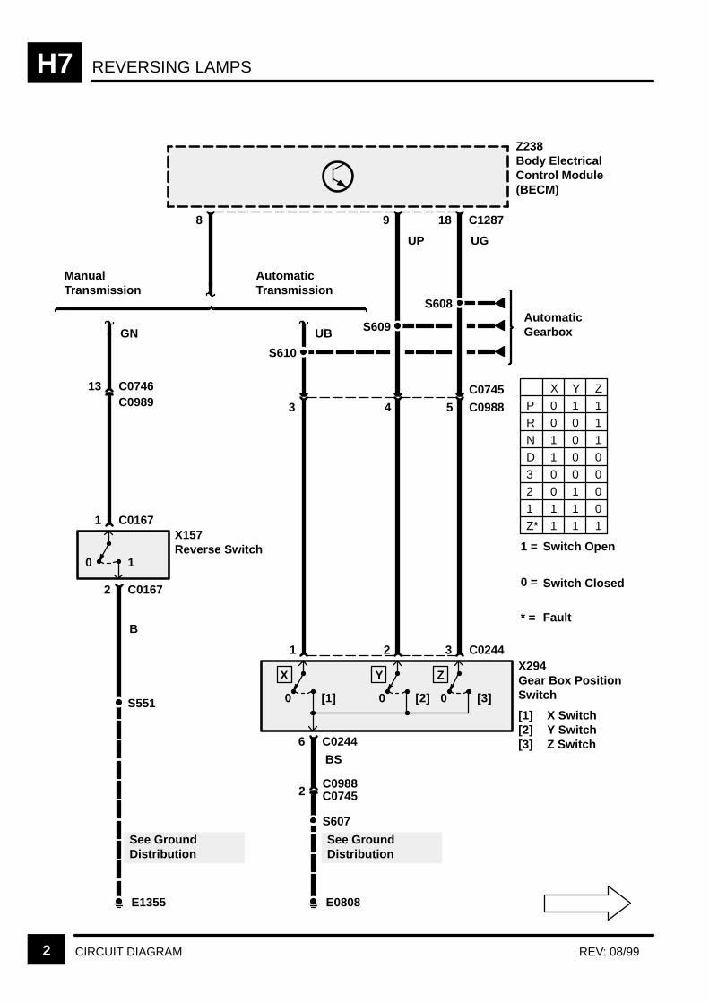
REVERSING LAMPSH7
2 CIRCUIT DIAGRAM REV: 08/99
Z238Body ElectricalControl Module(BECM)
2 C0167
AutomaticTransmission
ManualTransmission
13 C0746
0 1
X157Reverse Switch
S551
E1355
UP UG
S608
S609
S610
UB
6 C0244
0 [1]
X
1
0 [2]
Y
2
0 [3]
Z
3 C0244
GN
B
2C0988
BS
S607
E0808
C0989
1 C0167
See GroundDistribution
See GroundDistribution
C0745
X294Gear Box PositionSwitch
[1] X Switch[2] Y Switch[3] Z Switch
P 0 1 1R 0 0 1
N 1 0 1D 1 0 03 0 0 02 0 1 01 1 1 0Z* 1 1 1
X Y Z
AutomaticGearbox
1 =
0 =
* =
Switch Open
Switch Closed
Fault
3C0745C09884 5
8 9 18 C1287
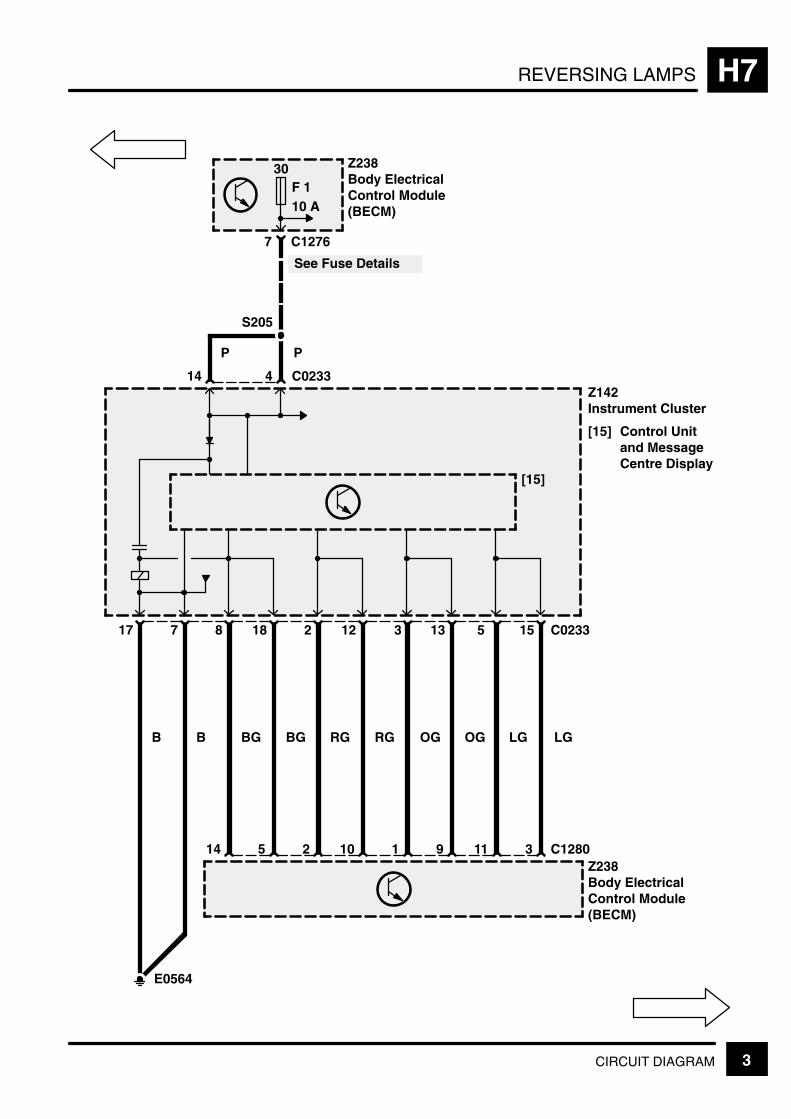
REVERSING LAMPS H7
3CIRCUIT DIAGRAM
5
Z238Body ElectricalControl Module(BECM)
7 C1276
17
14
[15]
4 C0233
B
S205
See Fuse Details
Z142Instrument Cluster
[15] Control Unitand MessageCentre Display
30F 110 A
7
B
Z238Body ElectricalControl Module(BECM)
8
BG
14
18
BG
5
2
2
12
10
RG RG
1
13
9
OGOG
E0564
P P
3 C0233
11
15
3
LGLG
C1280

REVERSING LAMPSH7
4 CIRCUIT DIAGRAM REV: 11/99
2
Z238Body ElectricalControl Module(BECM)
9C1584
GN
S301
C0697
E0565
C0789
See GroundDistribution
LGN
WW
[1]
B177Left Tailgate Lights
[1] Reverse
4 C0490
1 C0490
[1]
B178Right TailgateLights
[1] Reverse
2 C0489
1 C0489
2 1 C0789C0697
WW
BB
B
W See GroundDistribution
6 5
C1283(MY 2000)(MY 1999)

FOG GUARD LAMPS H9
CIRCUIT OPERATION 1
CIRCUIT OPERATION
Front Fog lamps
With the ignition switch and side lamp or headlampswitch on, a momentary operation of the front foglamp switch will activate the front fog lamps. A fur-ther momentary operation of the fog lamp switch, orswitching off of the headlamps/side lamps or ignition,will cause the front fog lamps to be extinguished.N.B. The front fog lamps will always be inactivewhen the ignition is turned on.
Rear Fog lamps
With the ignition on, the headlamp switch on or frontfog lamps on, a momentary operation of the rear foglamp switch will activate the rear fog lamps. Opera-tion of the rear fog lamps will also activate a bulbwithin the fog lamp switch. A further momentaryoperation of the fog lamp switch, switching off thehead lamps and front fog lamps, or switching off theignition, will cause the rear fog lamps to switch off.N.B. The rear fog lamps will always be inactive whenthe ignition is turned on.
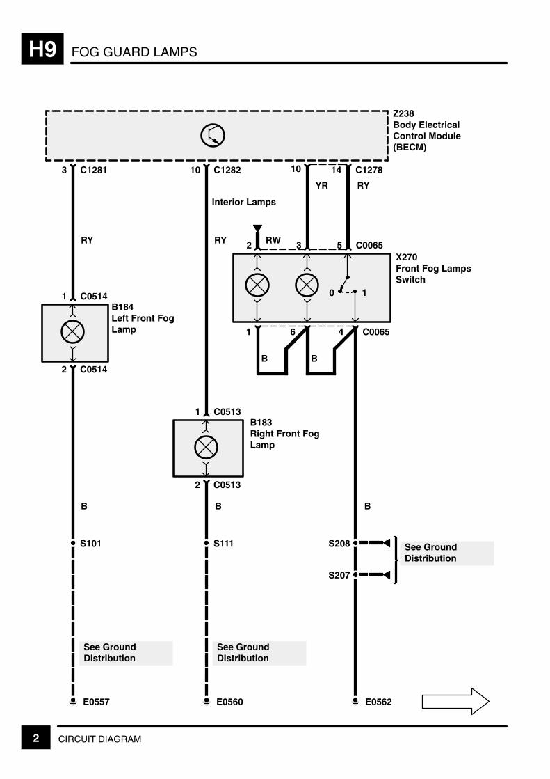
FOG GUARD LAMPSH9
2 CIRCUIT DIAGRAM
3
Z238Body ElectricalControl Module(BECM)
2 C0514
10 14 C1278
B184Left Front FogLamp
S101
E0557
1
2RY
B
1 C0514
See GroundDistribution
X270Front Fog LampsSwitch
C1281 10
2 C0513
B183Right Front FogLamp
S111
E0560
RY
B
1 C0513
See GroundDistribution
C1282
Interior Lamps
6
3
4 C0065
5
0 1
C0065
YR RY
RW
E0562
S207
S208 See GroundDistributionSee GroundDistribution
B
BB
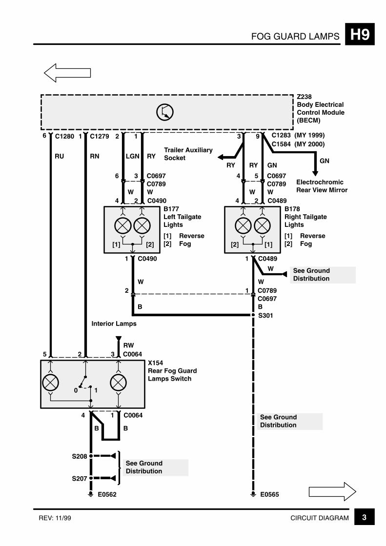
FOG GUARD LAMPS H9
3CIRCUIT DIAGRAMREV: 11/99
RYRY
2
Z238Body ElectricalControl Module(BECM)
6 1 C1279
1
3X154Rear Fog GuardLamps Switch
Interior Lamps
5
4 C0064
2
0 1
C0064
RU RN
RW
E0562
S207
S208
BB
2
1 C0490
B177Left TailgateLights
[1] Reverse[2] Fog
LGN
4
6 C0697
W
RY
C0490
3
W
1
W2 C07891
B
2
3
1 C0489
4
4 C0697
W
GN
C0489
5
W
9
W
B
C1584Trailer AuxiliarySocket
C0789 C0789
C0697
E0565
S301
See GroundDistribution
See GroundDistribution
[1] [2] [2] [1]
C1280
B178Right TailgateLights
[1] Reverse[2] Fog
W See GroundDistribution
C1283(MY 2000)(MY 1999)
GN
ElectrochromicRear View Mirror

FOG GUARD LAMPSH9
4 CIRCUIT DIAGRAM
5
Z238Body ElectricalControl Module(BECM)
7 C1276
17
14
[15]
4 C0233
B
S205
See Fuse Details
Z142Instrument Cluster
[15] Control Unitand MessageCentre Display
30F 110 A
7
B
Z238Body ElectricalControl Module(BECM)
8
BG
14
18
BG
5
2
2
12
10
RG RG
1
13
9
OGOG
E0564
P P
3 C0233
11
15
3
LGLG
C1280
INTERIOR LAMPS J1
CIRCUIT OPERATION 1
CIRCUIT OPERATION
Courtesy lamps
Automatic courtesy lamp facility enabled
With the tailgate or any of the four doors opened theillumination level of the following lamps will fade onover a period of approximately 0.5 seconds:
front courtesy lamp
rear left courtesy lamp
rear right courtesy lamp
load space lamps
front left footwell lamp
front right footwell lamp
ignition ring illumination
rear right footwell lamp
rear left footwell lamp
If any door is left open, the lamps will fade out after atime of approximately 10 minutes. During the 10minute time out, if any other door is opened the timerwill be reset.
If all doors are closed prior to the end of this 10minute period then all specified lamps will fade outafter a delay of 15 seconds.
If the ignition is switched on before the end of the 15second time out period, the specified lamps willbegin to fade out after a delay of 1 second.
If the ignition is then switched off and no dooropened, the 15 second time out of the lamps will notbe resumed.
If an unlock signal is received from the remote key,or if a key unlock is received from either of the frontdoors while all the doors are closed, then thecourtesy lamps will fade to on in 0.5 seconds andbegin a 15 second time out period.
If any of the doors or the tailgate are opened duringthis delay, then the time out period will be restarted.
If all the doors are closed and a lock signal isreceived from the remote key or either of the frontdoor CDL switches while the courtesy lamps are intheir 15 second time out period, then the time delaywill be cancelled and the lamps immediately fadedout.
Automatic courtesy lamp facility disabled
Whenever the main courtesy lamp switch is operatedfor greater than 2 seconds, the automatic courtesylamp feature will switch between the enabled anddisabled mode upon release of the switch. At the
same time an “Int lamps off”/“Int lamps auto”message will be displayed on the instrument pack.This extended switch operation will also extinguishthe courtesy lamps if the button has been depressedfor 2 seconds, causing the system to switch from theautomatic to disabled mode, but otherwise will haveno effect on their state.While the automatic courtesylamp facility is disabled, the courtesy lamps may onlybe switched on and off by momentary activation ofthe main courtesy lamp switch. The change of lampstate will occur on release of the switch.
Panel Dimmer:
Operation of the panel dimmer switch, with the sidelamps on, will alter the level of panel illuminationbetween approximately 6 and 94%. Depressing theswitch momentarily will cause the illumination toincrease or decrease to the next level. Holding theswitch closed will cause the illumination to ramptowards fully on or fully off.
The illumination level selected will be stored in theBeCM’s non–volatile memory whenever the driver’sseat store sequence is completed successfully, pro-vided the side lamp switch is on. If the side lampswitch is not on and a successful memory storesequence is completed, then the previously storedillumination level will remain unchanged.
INTERIOR LAMPSJ1
CIRCUIT OPERATION2
Puddle lamps
With any door open and the automatic courtesy lampfeature enabled, the puddle lamp within the relevantdoor will be illuminated, either until the door is closedor a time period of approximately 10 minutes haselapsed. If any puddle lamp is on, momentaryoperation of the courtesy lamp master switch willextinguish all puddle lamps on release of the switch.
Further operation of the switch or reopening a door(if automatic courtesy lamps are enabled) will againactivate the puddle lamps for those doors that areopen. If the courtesy lamp switch is held on forlonger than 2 seconds, the automatic operation ofthe puddle lamps from the door open switches willswitch between enabled and disabled.
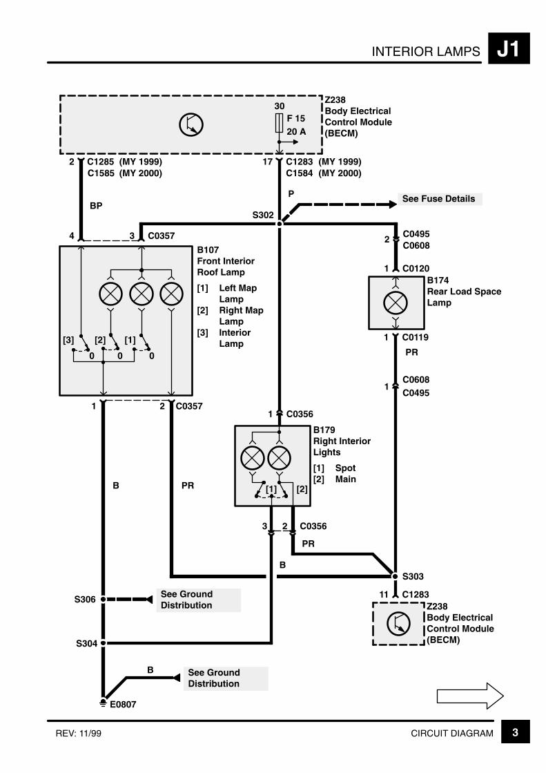
INTERIOR LAMPS J1
3CIRCUIT DIAGRAMREV: 11/99
2C1585
BP
17
P
1 C0120
1 C0119
E0807
S302
Z238Body ElectricalControl Module(BECM)
See Fuse Details
B174Rear Load SpaceLamp
30F 1520 A
2 C0495
1C0495
B179Right InteriorLights
[1] Spot[2] Main
1 C0356
2 C0356
[1] [2]
3
0
[1]
0
[2]
0
[3]
4 3 C0357
1 2 C0357
S304
11 C1283Z238Body ElectricalControl Module(BECM)
S303
S306 See GroundDistribution
See GroundDistribution
PR
B
B
B PR
PR
B107Front InteriorRoof Lamp
[1] Left MapLamp
[2] Right MapLamp
[3] InteriorLamp
C0608
C0608
C1285(MY 2000)(MY 1999) C1283 (MY 1999)
C1584 (MY 2000)

INTERIOR LAMPSJ1
4 CIRCUIT DIAGRAM REV: 11/99
10C1585
0[3]
Z238Body ElectricalControl Module(BECM)
919
LG R OG
C1383R
15 C1406
Z244Right Front DoorOutstation
1413
7 C1579R
PW
6 C1422
2 C0441R
M154Right Front DoorLock Actuator
[3] Door AjarSwitch
B
9 C1286
0[3]
11 C1579LZ243Left Front DoorOutstation
101
LG R OG
C1379L
15 C1580
Z243Left Front DoorOutstation
1413
7 C1579L
PW
4 C1421
2 C0441L
M153Left Front DoorLock Actuator
[3] Door AjarSwitch
B
S353
E0809
9 C15807
See GroundDistribution
11 C1579RZ244Right Front DoorOutstation
S307
E0807
9 C14067
See GroundDistribution
C1366 (MY 2000)621
(MY 2000)
(MY 2000)
5 C137343 (MY 1999)(MY 1999)
C1379R (MY 2000)
5 C136443 (MY 1999)C1383L (MY 1999)
C1383L (MY 1999)
6 C156821 (MY 2000)

INTERIOR LAMPS J1
5CIRCUIT DIAGRAMREV: 11/99
Z238Body ElectricalControl Module(BECM)
3 C1285
9C0697
[1]
PY
C0789
2 C0616
1 C0616
X170Tailgate Switch
[0] Close[1] Open
W
See GroundDistribution
E0565
4 C1286
3C1360
0[1]
PW
C1386L
4 C0302L
1 C0302L
See GroundDistribution
E0809
13 C1285
3C1369
0[1]
PW
C1386R
6 C0302R
3 C0302R
See GroundDistribution
E0807
S701L S701R
M150Right Rear DoorLock Actuator
[1] Door AjarSwitch
M149Left Rear DoorLock Actuator
[1] Door AjarSwitch
B178Right TailgateLights
W
C0489
1C0789C0697
W
B
S301
B B
C1585 (MY 2000)(MY 1999)
C1585 (MY 2000)(MY 1999)
[0]
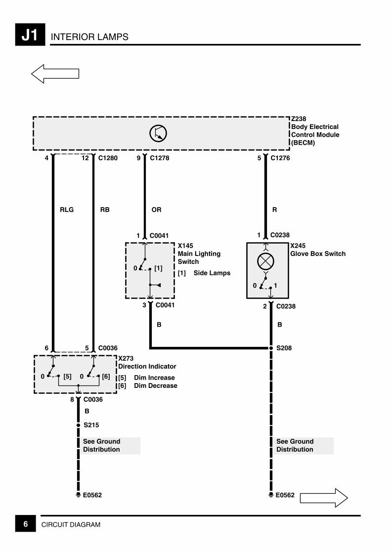
INTERIOR LAMPSJ1
6 CIRCUIT DIAGRAM
5 C1276
Z238Body ElectricalControl Module(BECM)
12 C12804
RB
5 C0036
8 C0036
X273Direction Indicator
[5] Dim Increase[6] Dim Decrease
B
9 C1278
R
1 C0238
2 C0238
X245Glove Box Switch
B
0 [1]
OR
1 C0041
3 C0041
X145Main LightingSwitch
[1] Side Lamps
B
S208
E0562
See GroundDistribution
RLG
6
[6]0[5]0
S215
See GroundDistribution
E0562
0 1
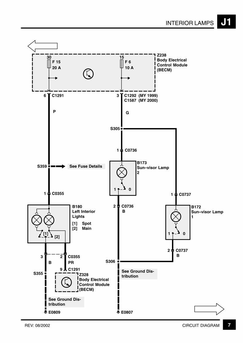
INTERIOR LAMPS J1
7CIRCUIT DIAGRAMREV: 08/2002
S359
3 C1292
Z238Body ElectricalControl Module(BECM)
G
B
S306
E0809
See Ground Dis-tribution
P
S355
See Ground Dis-tribution
E0807
01
S305
1 C0736
2 C0736B180Left InteriorLights
[1] Spot[2] Main
[2][1]
1 C0355
3 2 C0355
See Fuse Details
9 C1291Z328Body ElectricalControl Module(BECM)
PR
6 C1291
30F 1520 A
B
B173Sun–visor Lamp2
B172Sun–visor Lamp1
B
01
1 C0737
2 C0737
C1587 (MY 2000)(MY 1999)
15F 610 A

INTERIOR LAMPSJ1
8 CIRCUIT DIAGRAM REV: 11/99
6 C0098Z111Radio
8 C0098
1 C0095Z117Clock
2 C0232
6 C0792Z253HeatingVentilation andAir ConditioningControl Unit(HEVAC)
4 C0792
6 C0749
10
X115Cruise ControlSwitch
31
B
B
B B
B
2 4 C07495
WY OW
Z238Body ElectricalControl Module(BECM)
2 C1276
E0562
17 C0233
X145Main LightingSwitch
B
6 C0233
7
E0564
B
3 C0041
2 C0041
RW
E0562
Z142InstrumentCluster
S208
S209
S210
S208
See GroundDistribution
See GroundDistribution
B
Cruise Control
B
Partial
A
J1-9
E0361
NavigationSystem

INTERIOR LAMPS J1
9CIRCUIT DIAGRAM
4 C0065
X270Front Fog LampsSwitch
61B B
2 5 C00653
YR RY
E0562
S208
A
J1-8
10
X271Ride HeightSwitch
7 C0893
2 C0893
B
4 C0064
X154Rear Fog GuardLamps Switch
1B
3 2 C00645
RU RN
Fog GuardLamps
10
1 C0096
X220Hazard Switch
3B
45 C00962
PG GLG
DirectionIndicator Lamps
10
1 C0894
X209AirSuspensionInhibit Switch
6B
24 C08945
YS W
Air Suspension
10
S209 Partial
RW RW RW
B
B
3
RW
B
Fog GuardLamps
See GroundDistribution
RW
RW

INTERIOR LAMPSJ1
10 CIRCUIT DIAGRAM
9 C0675Z254’H’ Gate SensorModule
1 C0675
RU
B
6 C06851B
35 C06852
PG GP
Transfer Gearbox
[1]0[2]
Z238Body ElectricalControl Module(BECM)
11 C1290
RU
1 C1594
1 C1595
5 C0081
Z259Centre ConsoleSwitch PackOutstation
6 C0081
B
B106Fascia CigarLighter
See GroundDistribution
S612
ManualTransmission
AutomaticTransmission
RU
S611
S607
E0808
B
1C1444C1391
4 C1391C1444
B
See GroundDistribution
X297Transfer SwitchManual

INTERIOR LAMPS J1
11CIRCUIT DIAGRAM
2 C0076
1 C0076B168Footwell Lamp 1
S205
1 C0891
3 C1276Z238Body ElectricalControl Module(BECM)
12 C1290
2 C0077
1 C0077B169Footwell Lamp 2
B170Key Illumination
30
10 A
S216
P
LHD RHD
P P
P
LHD RHD
8 C1290
Z238Body ElectricalControl Module(BECM)
See FuseDetails
See FuseDetails
1 C1442
2 C1442B182Rear FootwellLamp
PU
F 1
PR PRPR PW
S204
PU7 C1276
2 C0891
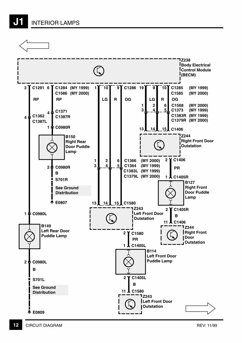
INTERIOR LAMPSJ1
12 CIRCUIT DIAGRAM REV: 11/99
13 C1291
RP
2 C0980L
B149Left Rear DoorPuddle Lamp
1 C0980L
2 C0980R
B150Right RearDoor PuddleLamp
1 C0980R
S701L
E0809
B
B
S701R
E0807
Z238Body ElectricalControl Module(BECM)
4 C1362C1387L
6 C1284
4 C1371C1387R
RP
See GroundDistribution
See GroundDistribution
11 C1580Z243Left Front DoorOutstation
2 C1405L
1 C1405LB114Left Front DoorPuddle Lamp
B
2 C1405R
1 C1405RB127Right FrontDoor PuddleLamp
B
11 C1406Z244Right FrontDoorOutstation
10 C1285919
5 C1373C1383R
43
OGRLG
9 C128610
5 C1364C1383L
43
OGRLG
15 C1406
Z244Right Front DoorOutstation
1413
15 C15801413Z243Left Front DoorOutstation
2 C1580
2 C1406
PR
PR
C1586 (MY 2000)(MY 1999)
(MY 1999)(MY 1999)
6 C136621 (MY 2000)
C1379L (MY 2000)
C1585 (MY 2000)(MY 1999)
6 C156821 (MY 2000)(MY 1999)(MY 1999)(MY 2000)C1379R

INTERIOR LAMPS J1
13CIRCUIT DIAGRAMREV: 11/99
Z238Body ElectricalControl Module(BECM)
RN
16
2
E0809
C1291
C1385LC1361
1
3
S701L
C0732L
X188Left Rear WindowDoor Switch
C0732L
B
See GroundDistribution
RN
11
2
E0807
C1284
C1385RC1370
1
3
S701R
C0732R
X189Right RearWindow DoorSwitch
C0732R
B
See GroundDistribution
C1586 (MY 2000)(MY 1999)

KEY INFORMATIONi
!"
#$ % &'( ' )
*$ % &'( + %
,# % &'( ' )
% &'( ' )
-
*, !+
!
+ ' '
+ .) . . '
/+ +0 .
' /'+0
"% ) '
+ ) . % .
+ +- %
. )
(
.
!"
. ' % 1(
2 + " .
' ) '
2 +' 3 .
.' % '
2 .) % '
2 4 .' % '-
&+
+ )
+ /0 .
+ ' %

CIGAR LIGHTER/CLOCK/ACCESSORY SOCKET J2
1CIRCUIT DIAGRAMREV: 11/99
30F 830 A
RL7
5 C1290
Z238Body ElectricalControl Module(BECM)
30F 110 A
7 C1276
See Fuse Details
E0562
S205
P
G
E0562
S207
See GroundDistribution
See GroundDistribution
B
B
1 C0232
RW
1 C0095Z117Clock
Interior Lamps
2 C0232
2 C1594 1 C1595B106Fascia CigarLighter
1 C1594
RU
Interior Lamps5
2 C0350
1 C0350
P4AccessorySocket
E0565
S301
See GroundDistribution
B
S208
C1584
G
(MY 2000)

KEY INFORMATIONi
!"
#$ % &'( ' )
*$ % &'( + %
,# % &'( ' )
% &'( ' )
-
*, !+
!
+ ' '
+ .) . . '
/+ +0 .
' /'+0
"% ) '
+ ) . % .
+ +- %
. )
(
.
!"
. ' % 1(
2 + " .
' ) '
2 +' 3 .
.' % '
2 .) % '
2 4 .' % '-
&+
+ )
+ /0 .
+ ' %
HEATING AND VENTILATION (WITHOUT A/C) K3
CIRCUIT OPERATION 1
CIRCUIT OPERATION
Ignition position 1 (Accessories)
This feed is obtained from the BeCM via fuse 8 andis shared with the Radio, Front cigar lighter and carphone (if fitted). The Ignition 1 is essential to thecontrol panel as it provides power to the ECUalthough no functions or display on the LCD arepossible.
Ignition position 2
This feed is obtained from the BeCM via fuse 35.
Ground Connection
This feed runs down to a spliced joint, joining themain earth run down to fascia earth point E0652.
Dimmer Line
This Pulse Width Modulated signal is provided by theBeCM.
LCD Dimmer line
This line is a input to the HEVAC and the signal is ainverse Pulse Width Modulated signal which isdetermined by the instrument pack.
Alternator Charge signal
This signal is given to the HEVAC ECU to inform itthat the engine is running. This signal is active low.
Diagnostic K line
This line is used to communicate with the diagnosticequipment (TESTBOOK) and is normally held at 12Vwhen not active.
Left/Right Recirculation motors
These motors control the flaps on the blower motormodules. The flaps should be in one of twopositions, either fully open or fully closed.
Left/Right Blower modules
The blowers have a permanent 12V feed to them.The speed of the motors is determined by the controllines which go to the motors. The motors alsoprovide a voltage feedback to the HEVAC ECU todetermine the actual voltage at the motors but alsoto show if there are any faults.
Left/Right Blend and Distribution Motors
These motors are controlled by the HEVAC ECUwhich provides power to the motors, which in turnreport back their actual positions to the HEVACECU.
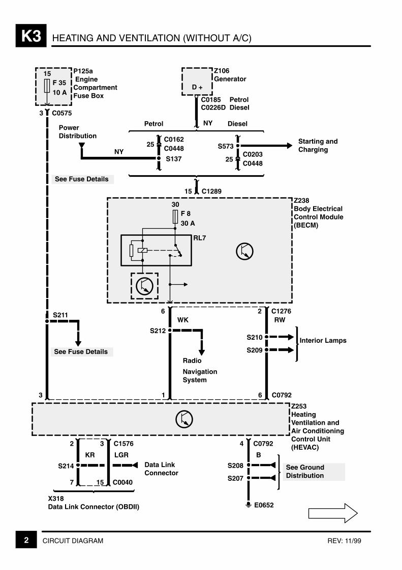
HEATING AND VENTILATION (WITHOUT A/C)K3
2 CIRCUIT DIAGRAM REV: 11/99
25C0448
NY
C0162
25C0448C0203
15 C1289
Petrol Diesel
Z106Generator
S573Starting andCharging
D +
6
30F 830 A
Z238Body ElectricalControl Module(BECM)
RL7
2 C1276
S210
S209
RW
S212Interior Lamps
WKS211
See Fuse Details
Z253HeatingVentilation andAir ConditioningControl Unit(HEVAC)
3 1 6 C0792
4 C0792
S208
S207
B
E0652
Data LinkConnector
LGRKR
15 C00407
S214
X318Data Link Connector (OBDII)
See GroundDistribution
P125a EngineCompartmentFuse Box
15F 3510 A
3
See Fuse Details
C0575
3 C15762
C0226DC0185 Petrol
Diesel
PowerDistribution
NYS137
Radio
NavigationSystem
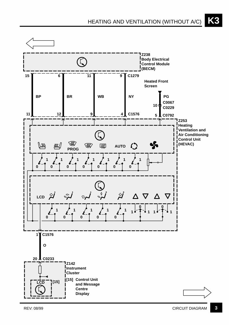
HEATING AND VENTILATION (WITHOUT A/C) K3
3CIRCUIT DIAGRAMREV: 08/99
Z238Body ElectricalControl Module(BECM)
15
BP
C12796
BR
11
WB
9
NY PG
5 C0792
10C0067C0229
Z253HeatingVentilation andAir ConditioningControl Unit(HEVAC)
Heated FrontScreen
0
1
0
1
0
1
0
1
0
1
0
1
0
1
AUTOPROG
0
1
0
1
0
1
0
1
0
1 10
1 10
1
C023320Z142InstrumentCluster
[15] Control Unitand MessageCentreDisplay
[15]LCD
LCD
C157611 12 9 4
1 C1576
O
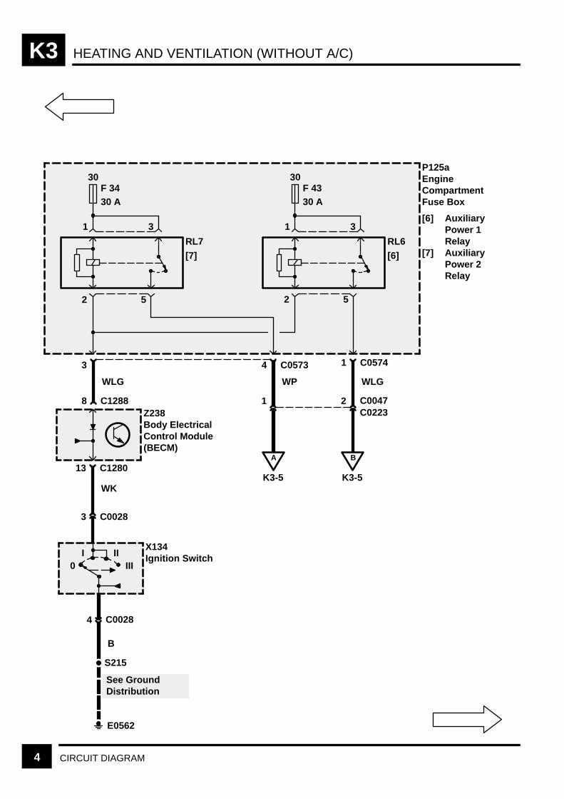
HEATING AND VENTILATION (WITHOUT A/C)K3
4 CIRCUIT DIAGRAM
30F 3430 A
RL7
[7]
31
2 5
30F 4330 A
RL6
[6]
31
1 C0574
WLG
2 C0047
B
K3-5
4 C0573
WP
1
A
K3-5
S215
E0562
See GroundDistribution
B
3 C0028
4 C0028
0I II
III
X134Ignition Switch
P125aEngineCompartmentFuse Box
[6] AuxiliaryPower 1Relay
[7] AuxiliaryPower 2Relay
3
WLG
8 C1288
13 C1280
Z238Body ElectricalControl Module(BECM)
WK
2 5
C0223
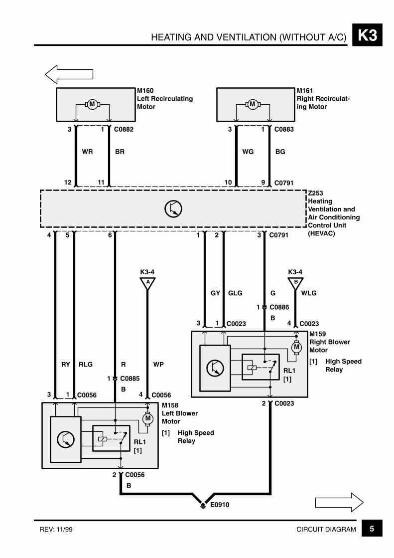
HEATING AND VENTILATION (WITHOUT A/C) K3
5CIRCUIT DIAGRAMREV: 11/99
C07916
11
1 C08823
M
WR BR
C079112
M160Left RecirculatingMotor
9
1 C08833
M
WG BG
10
M161Right Recirculat-ing Motor
Z253HeatingVentilation andAir ConditioningControl Unit(HEVAC)
M
M158Left BlowerMotor
[1] High SpeedRelay
C00561
RLG
3
RY
K3-4
4
A
R
4 5
E0910
C00562
B
WP
C0056
1 C0885
B
M
M159Right BlowerMotor
[1] High SpeedRelay
C00231
GLG
3
GY
K3-4
4
B
G
C00232
WLG
C0023
1 C0886
B
31 2
RL1[1]
RL1[1]
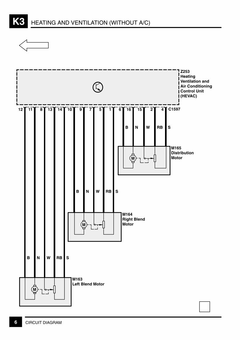
HEATING AND VENTILATION (WITHOUT A/C)K3
6 CIRCUIT DIAGRAM
C1597
Z253HeatingVentilation andAir ConditioningControl Unit(HEVAC)
4
S
2
RB
15
W
16
N
6
B
1
S
5
RB
7
W
9
N
10
B
14
S
13
RB
8
W
11
N
12
B
M
M
M
M165DistributionMotor
M164Right BlendMotor
M163Left Blend Motor
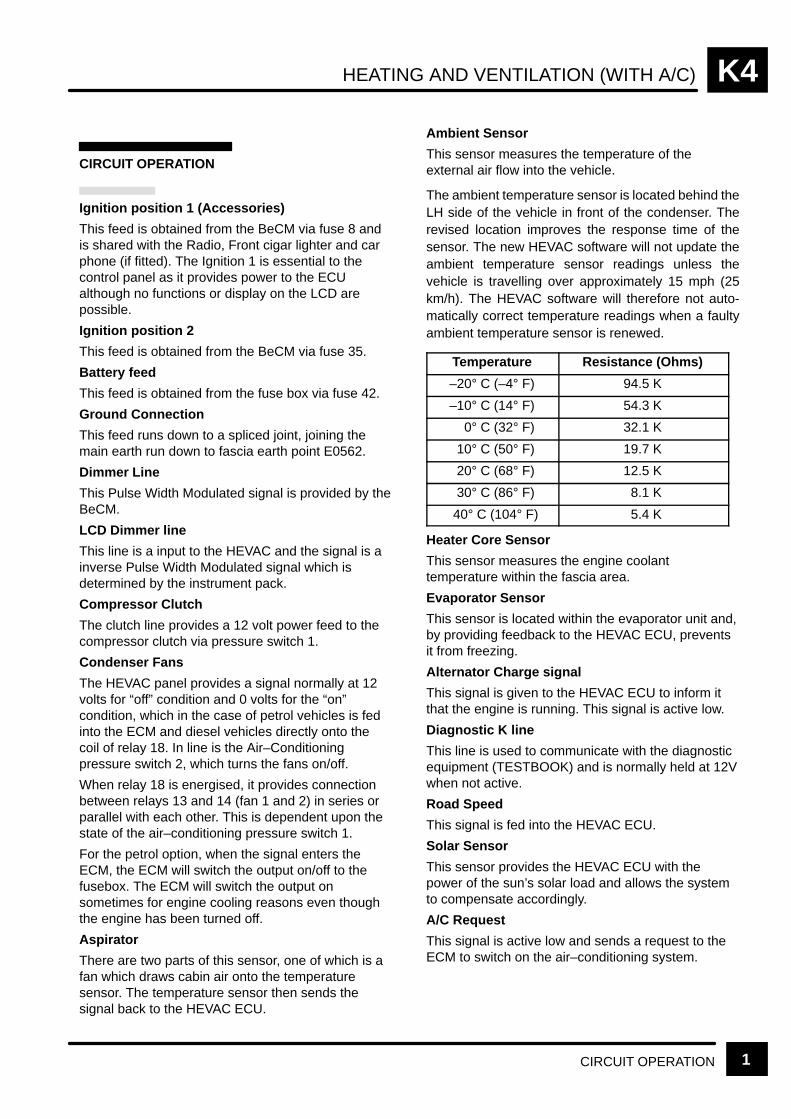
HEATING AND VENTILATION (WITH A/C) K4
CIRCUIT OPERATION 1
CIRCUIT OPERATION
Ignition position 1 (Accessories)
This feed is obtained from the BeCM via fuse 8 andis shared with the Radio, Front cigar lighter and carphone (if fitted). The Ignition 1 is essential to thecontrol panel as it provides power to the ECUalthough no functions or display on the LCD arepossible.
Ignition position 2
This feed is obtained from the BeCM via fuse 35.
Battery feed
This feed is obtained from the fuse box via fuse 42.
Ground Connection
This feed runs down to a spliced joint, joining themain earth run down to fascia earth point E0562.
Dimmer Line
This Pulse Width Modulated signal is provided by theBeCM.
LCD Dimmer line
This line is a input to the HEVAC and the signal is ainverse Pulse Width Modulated signal which isdetermined by the instrument pack.
Compressor Clutch
The clutch line provides a 12 volt power feed to thecompressor clutch via pressure switch 1.
Condenser Fans
The HEVAC panel provides a signal normally at 12volts for “off” condition and 0 volts for the “on”condition, which in the case of petrol vehicles is fedinto the ECM and diesel vehicles directly onto thecoil of relay 18. In line is the Air–Conditioningpressure switch 2, which turns the fans on/off.
When relay 18 is energised, it provides connectionbetween relays 13 and 14 (fan 1 and 2) in series orparallel with each other. This is dependent upon thestate of the air–conditioning pressure switch 1.
For the petrol option, when the signal enters theECM, the ECM will switch the output on/off to thefusebox. The ECM will switch the output onsometimes for engine cooling reasons even thoughthe engine has been turned off.
Aspirator
There are two parts of this sensor, one of which is afan which draws cabin air onto the temperaturesensor. The temperature sensor then sends thesignal back to the HEVAC ECU.
Ambient Sensor
This sensor measures the temperature of theexternal air flow into the vehicle.
The ambient temperature sensor is located behind theLH side of the vehicle in front of the condenser. Therevised location improves the response time of thesensor. The new HEVAC software will not update theambient temperature sensor readings unless thevehicle is travelling over approximately 15 mph (25km/h). The HEVAC software will therefore not auto-matically correct temperature readings when a faultyambient temperature sensor is renewed.
Temperature Resistance (Ohms)
–20° C (–4° F) 94.5 K
–10° C (14° F) 54.3 K
0° C (32° F) 32.1 K
10° C (50° F) 19.7 K
20° C (68° F) 12.5 K
30° C (86° F) 8.1 K
40° C (104° F) 5.4 K
Heater Core Sensor
This sensor measures the engine coolanttemperature within the fascia area.
Evaporator Sensor
This sensor is located within the evaporator unit and,by providing feedback to the HEVAC ECU, preventsit from freezing.
Alternator Charge signal
This signal is given to the HEVAC ECU to inform itthat the engine is running. This signal is active low.
Diagnostic K line
This line is used to communicate with the diagnosticequipment (TESTBOOK) and is normally held at 12Vwhen not active.
Road Speed
This signal is fed into the HEVAC ECU.
Solar Sensor
This sensor provides the HEVAC ECU with thepower of the sun’s solar load and allows the systemto compensate accordingly.
A/C Request
This signal is active low and sends a request to theECM to switch on the air–conditioning system.

HEATING AND VENTILATION (WITH A/C)K4
CIRCUIT OPERATION2
A/C Grant
This signal is active low and sends a signal to theHEVAC ECU to acknowledge the request signal andthat it is ready for the load to be switched on by theHEVAC system.
Pressure switch 1 (Trinary switch)
This switch is in parallel with two components, thecondensor fans and the compressor clutch which areboth normally short circuit. If the pressure is too highor too low, the switch will open and cut the feed tothe clutch to prevent damage to the system. With thethird setting, at a specific pressure the switch isshorted and changes the condenser fan mode fromseries to parallel.
Pressure switch 2 (Single switch)
The switch is normally open circuit. At a specificpressure, the switch is shorted and allows thecondenser fans to turn on.
Left/Right Recirculation motors
These motors control the flaps on the blower motormodules. The flaps should be in one of twopositions, either fully open or fully closed.
Left/Right Blower modules
The blowers have a permanent 12V feed to them.The speed of the motors is determined by the controllines which go to the motors. The motors alsoprovide a voltage feedback to the HEVAC ECU todetermine the actual voltage at the motors but alsoto show if there are any faults.
Left/Right Blend and Distribution Motors
These motors are controlled by the HEVAC ECUwhich provides power to the motors, which in turnreport back their actual positions to the HEVACECU.
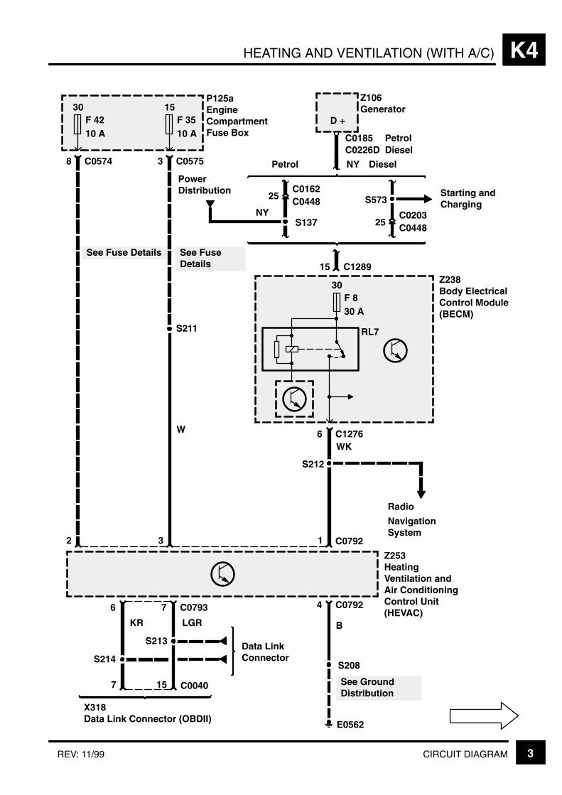
HEATING AND VENTILATION (WITH A/C) K4
3CIRCUIT DIAGRAMREV: 11/99
Data LinkConnector
25C0448
NY
C0162
25C0448C0203
15 C1289
Petrol Diesel
Z106Generator
S573Starting andCharging
D +
6
30F 830 A
Z238Body ElectricalControl Module(BECM)
RL7
C1276
S212
WK
Z253HeatingVentilation andAir ConditioningControl Unit(HEVAC)
1
4 C0792
S208
E0562
6 7 C0793
LGRKR
15 C00407
S213
S214
X318Data Link Connector (OBDII)
B
See GroundDistribution
P125aEngineCompartmentFuse Box
30F 4210 A
8 C0574
15F 3510 A
3 C0575
32
S211
See Fuse Details
C0226DC0185
C0792
PetrolDiesel
Radio
See FuseDetails
PowerDistribution
NYS137
W
NavigationSystem

HEATING AND VENTILATION (WITH A/C)K4
4 CIRCUIT DIAGRAM REV: 11/99
S209
Z238Body ElectricalControl Module(BECM)
C12762RW
6 C0792
PG
5 C0792
10C0067C0229
Z253HeatingVentilation andAir ConditioningControl Unit(HEVAC)
Heated FrontScreen
0
1
0
1
0
1
0
1
0
1
0
1
0
1
AUTOPROG
0
1
0
1
0
1
0
1
0
1 10
1 10
1
C079311OC023320
Z142InstrumentCluster
[15] Control Unitand MessageCentreDisplay
[15]LCD
LCD
15
BP
20
6
BR
19
11
WB
17
9
NY
8
10Y
5
C1279
Interior Lamps
S210
0
1
A/C
OFF
Z108Anti–Lock BrakeSystem ECU
C15843
11 C1289YGC0504
LHDRHD
C0793
S218
Radio
NY
NavigationSystem
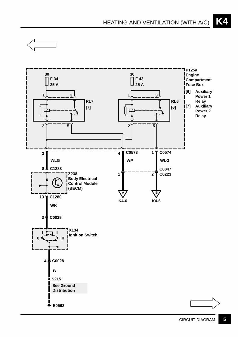
HEATING AND VENTILATION (WITH A/C) K4
5CIRCUIT DIAGRAM
30F 3425 A
RL7
[7]
31
2 5
30F 4325 A
RL6
[6]
31
1 C0574
WLG
2 C0223C0047
B
K4-6
4 C0573
WP
1
A
K4-6
S215
E0562
See GroundDistribution
B
3 C0028
4 C0028
0I II
III
X134Ignition Switch
P125aEngineCompartmentFuse Box
[6] AuxiliaryPower 1Relay
[7] AuxiliaryPower 2Relay
3
WLG
8 C1288
13 C1280
Z238Body ElectricalControl Module(BECM)
WK
2 5

HEATING AND VENTILATION (WITH A/C)K4
6 CIRCUIT DIAGRAM
C07916
11
1 C08823
M
WR BR
C079112
M160Left RecirculatingMotor
9
1 C08833
M
WG BG
10
M161Right Recirculat-ing Motor
M
C00561
RLG
3
RY
K4-5
4
A
R
4 5
E0910
C00562
B
WP
C0056
1 C0885
B
M
C00231
GLG
3
GY
K4-5
4
B
G
C00232
WLG
C0023
1 C0886
B
31 2
RL
RL
M158Left BlowerMotor
[1] High SpeedRelay
M159Right BlowerMotor
[1] High SpeedRelay
[1]
[1]
Z253HeatingVentilation andAir ConditioningControl Unit(HEVAC)
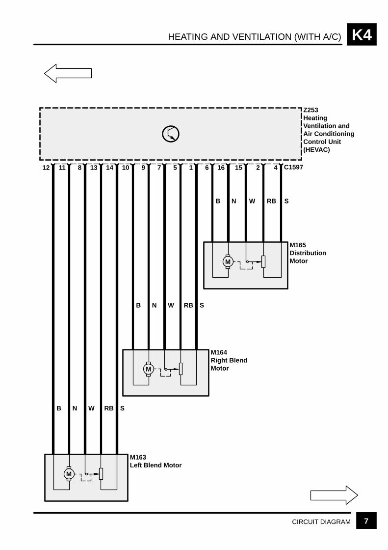
HEATING AND VENTILATION (WITH A/C) K4
7CIRCUIT DIAGRAM
C1597
Z253HeatingVentilation andAir ConditioningControl Unit(HEVAC)
4
S
2
RB
15
W
16
N
6
B
1
S
5
RB
7
W
9
N
10
B
14
S
13
RB
8
W
11
N
12
B
M
M
M
M165DistributionMotor
M164Right BlendMotor
M163Left Blend Motor
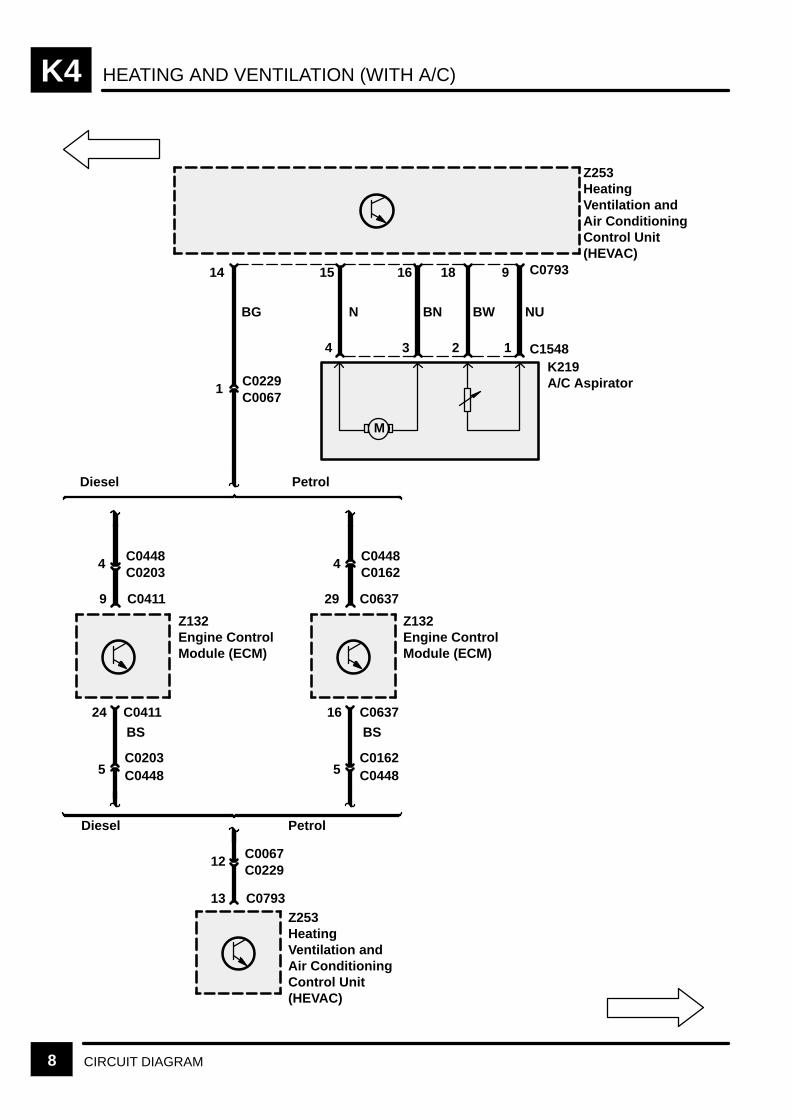
HEATING AND VENTILATION (WITH A/C)K4
8 CIRCUIT DIAGRAM
M
Z253HeatingVentilation andAir ConditioningControl Unit(HEVAC)
14 15 16 18 9 C0793
BG N BN BW NU
4 3 2 1 C1548K219A/C Aspirator
Diesel Petrol
4 C0448C0203
9 C0411
Z132Engine ControlModule (ECM)
4 C0448C0162
29 C0637
Z132Engine ControlModule (ECM)
24 C0411
BS
5C0203C0448
Diesel Petrol
16 C0637
BS
5C0162C0448
12 C0067C0229
13 C0793Z253HeatingVentilation andAir ConditioningControl Unit(HEVAC)
1 C0229C0067
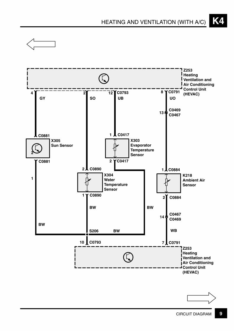
HEATING AND VENTILATION (WITH A/C) K4
9CIRCUIT DIAGRAM
K218Ambient AirSensor
C0793
S206
UO4 2 12 8 C0791
1 C0884
2 C0884
WB
7 C0791
Z253HeatingVentilation andAir ConditioningControl Unit(HEVAC)
Z253HeatingVentilation andAir ConditioningControl Unit(HEVAC)
UBSOGY
2
C0881
1
C0881
BW
10 C0793
BW
1 C0890
X303EvaporatorTemperatureSensor
X304WaterTemperatureSensor
2 C0890
1 C0417
2 C0417
BW
X305Sun Sensor
BW
13C0469C0467
14C0467C0469

HEATING AND VENTILATION (WITH A/C)K4
10 CIRCUIT DIAGRAM REV: 09/2001
S506
E1355
2 C0128
7 C0792
[2]
7 C0067C0229BY
1 C0844
[1]
2 C0844
WLG
1 C0127
1 C0128
See GroundDistribution
Z253HeatingVentilation andAir ConditioningControl Unit(HEVAC)
X315A/C Dual Pressure Switch
[1] < 1.2 Bar (17 psi)[2] > 30 Bar (435 psi)[3] > 2.4 Bar (35 psi)
< 21 Bar (305 psi)
K107CompressorClutch
K107CompressorClutch
DieselPetrol
B
[3]
2 C0162C0448
1 C0277C0182
GW5 C0575
6 C0571
2 C0574
30F 2710 A
S114
E0559
P125aEngineCompartmentFuse Box
[3] A/C DualPressureSwitchRelay
B
See GroundDistribution
RL 3[3]

HEATING AND VENTILATION (WITH A/C) (PETROL) K4
11CIRCUIT DIAGRAM
30F 3130 A
6 C0574
1 C0025
BN
P125aEngineCompartmentFuse Box
M113Left CondenserFan Motor
2 C0025
C
K4-12
BN
M
Petrol

HEATING AND VENTILATION (WITH A/C) (PETROL)K4
12 CIRCUIT DIAGRAM
F 3730 A
X312Pressure Switch2
[1] < 13 Bar(189 psi)
[2] > 17 Bar(247 psi)
P125aEngineCompartmentFuse Box
[13] A/CCondenserFan 1 Relay
[14] A/CCondenserFan 2 Relay
[18] A/C ControlRelay
[19] Engine MainControlRelay
K4-11
RL19
[19]
31
2 5
RL13
[13]
13
254
30F 3630 A
15 15
RL18
[18]
51
2 3SequentialMultiport FuelInjection (SFI–V8)
RL14
[14]
14
23
5
4
2 C0570
C
BN
BN3 C0571
BS114
E0559
See GroundDistribution
2 C0576BR
M121RightCondenserFan Motor
See GroundDistribution
1 C0280
2 C0280
B
M
2 C0571BU
[5][4]
3 C0844
S122
B
4 C0844
X315A/C DualPressure Switch
[4] < 17 Bar (247 psi)
[5] > 21 Bar (305 psi)
Petrol
See GroundDistribution
8 C0792Z253Heating Ventilation and AirConditioning Control Unit(HEVAC)
[2]
2 C0845
[1]
1 C0845
11 C0229C0067
YB
30
SequentialMultiport FuelInjection (SFI–V8)
E0560E0560
S139
30
S111

HEATING AND VENTILATION (WITH A/C) (DIESEL) K4
13CIRCUIT DIAGRAM
30F 3130 A
6 C0574
1 C0025
BN
P125aEngineCompartmentFuse Box
M113Left CondenserFan Motor
2 C0025
D
K4-14
M
Diesel
BN
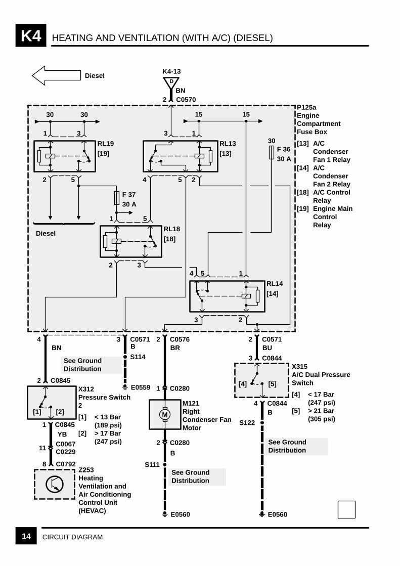
HEATING AND VENTILATION (WITH A/C) (DIESEL)K4
14 CIRCUIT DIAGRAM
X312Pressure Switch2
[1] < 13 Bar(189 psi)
[2] > 17 Bar(247 psi)
P125aEngineCompartmentFuse Box
[13] A/CCondenserFan 1 Relay
[14] A/CCondenserFan 2 Relay
[18] A/C ControlRelay
[19] Engine MainControlRelay
K4-13
RL19
[19]
31
2 5
RL13
[13]
13
254
30F 3630 A
15 15
RL18
[18]
51
2 3
Diesel
RL14
[14]
14
23
5
4
2 C0570
D
BN
8 C0792
BN
Z253HeatingVentilation andAir ConditioningControl Unit(HEVAC)
3 C0571B
S114
E0559
See GroundDistribution
2 C0576BR
M121RightCondenser FanMotor
S111
E0560
See GroundDistribution
1 C0280
2 C0280
B
M
2 C0571BU
[5][4]
3 C0844
S122
E0560
B4 C0844
X315A/C Dual PressureSwitch
[4] < 17 Bar(247 psi)
[5] > 21 Bar(305 psi)
Diesel
[2]
2 C0845
[1]
1 C0845
11 C0229C0067YB
See GroundDistribution
30 30
F 3730 A
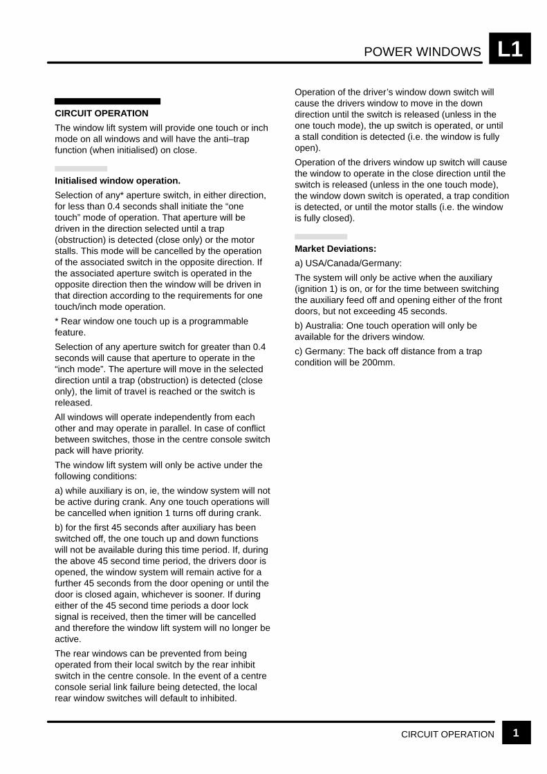
POWER WINDOWS L1
CIRCUIT OPERATION 1
CIRCUIT OPERATION
The window lift system will provide one touch or inchmode on all windows and will have the anti–trapfunction (when initialised) on close.
Initialised window operation.
Selection of any* aperture switch, in either direction,for less than 0.4 seconds shall initiate the “onetouch” mode of operation. That aperture will bedriven in the direction selected until a trap(obstruction) is detected (close only) or the motorstalls. This mode will be cancelled by the operationof the associated switch in the opposite direction. Ifthe associated aperture switch is operated in theopposite direction then the window will be driven inthat direction according to the requirements for onetouch/inch mode operation.
* Rear window one touch up is a programmablefeature.
Selection of any aperture switch for greater than 0.4seconds will cause that aperture to operate in the“inch mode”. The aperture will move in the selecteddirection until a trap (obstruction) is detected (closeonly), the limit of travel is reached or the switch isreleased.
All windows will operate independently from eachother and may operate in parallel. In case of conflictbetween switches, those in the centre console switchpack will have priority.
The window lift system will only be active under thefollowing conditions:
a) while auxiliary is on, ie, the window system will notbe active during crank. Any one touch operations willbe cancelled when ignition 1 turns off during crank.
b) for the first 45 seconds after auxiliary has beenswitched off, the one touch up and down functionswill not be available during this time period. If, duringthe above 45 second time period, the drivers door isopened, the window system will remain active for afurther 45 seconds from the door opening or until thedoor is closed again, whichever is sooner. If duringeither of the 45 second time periods a door locksignal is received, then the timer will be cancelledand therefore the window lift system will no longer beactive.
The rear windows can be prevented from beingoperated from their local switch by the rear inhibitswitch in the centre console. In the event of a centreconsole serial link failure being detected, the localrear window switches will default to inhibited.
Operation of the driver’s window down switch willcause the drivers window to move in the downdirection until the switch is released (unless in theone touch mode), the up switch is operated, or untila stall condition is detected (i.e. the window is fullyopen).
Operation of the drivers window up switch will causethe window to operate in the close direction until theswitch is released (unless in the one touch mode),the window down switch is operated, a trap conditionis detected, or until the motor stalls (i.e. the windowis fully closed).
Market Deviations:
a) USA/Canada/Germany:
The system will only be active when the auxiliary(ignition 1) is on, or for the time between switchingthe auxiliary feed off and opening either of the frontdoors, but not exceeding 45 seconds.
b) Australia: One touch operation will only beavailable for the drivers window.
c) Germany: The back off distance from a trapcondition will be 200mm.
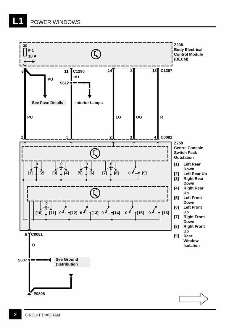
POWER WINDOWSL1
2 CIRCUIT DIAGRAM
See GroundDistribution
30F 110 A
See Fuse Details
PU
PU
8 C129011RU
S612
Interior Lamps
1 5
LG
14
2
OG
2
3
R
13
4
Z238Body ElectricalControl Module(BECM)
Z259Centre ConsoleSwitch PackOutstation
[1] Left RearDown
[2] Left Rear Up[3] Right Rear
Down[4] Right Rear
Up[5] Left Front
Down[6] Left Front
Up[7] Right Front
Down[8] Right Front
Up[9] Rear
WindowIsolation
C1287
C0081
0
[1] [2]
0
[3] [4]
0
[5] [6]
0
[7] [8] 0 [9]
0
[10] [11] 0 [12] 0 [13] 0 [14] 0 [15] 0 [16]
E0808
B
6 C0081
S607
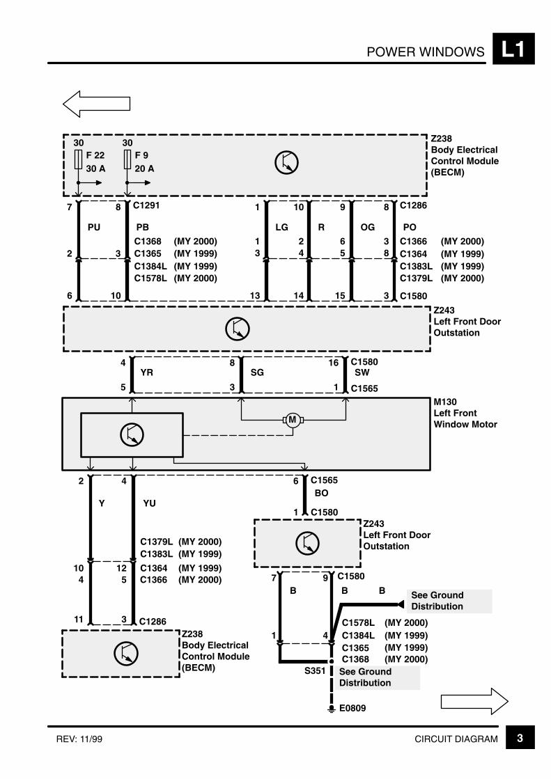
POWER WINDOWS L1
3CIRCUIT DIAGRAMREV: 11/99
(MY 1999)
PO
8 C1286
Z238Body ElectricalControl Module(BECM)
3 C1580
Z243Left Front DoorOutstation
30F 2230 A
30F 920 A
12 C1364
C1383L
8C1383LC1364
Z243Left Front DoorOutstation
OG
9
15
5
R
10
14
4
LG
1
13
3
PB
8 C1291
10
3C1384LC1365
PU
7
6
2
16 C158084SWSGYR
1 C156535
M130Left FrontWindow MotorM
42
YUY1 C1580
11
10
6 C1565BO
Z238Body ElectricalControl Module(BECM)
3 C1286
7B
9 C1580
B
E0809
See GroundDistribution
S351
4C1365C1384L1
B See GroundDistribution
C1578L (MY 2000)(MY 1999)
C1368 (MY 2000) 3 C1366621(MY 1999)
(MY 2000)(MY 1999)
(MY 2000)
C1379L
(MY 1999)C1379L (MY 2000)
5 C13664 (MY 2000)(MY 1999)
C1578L
C1368 (MY 2000)(MY 1999)(MY 1999)(MY 2000)
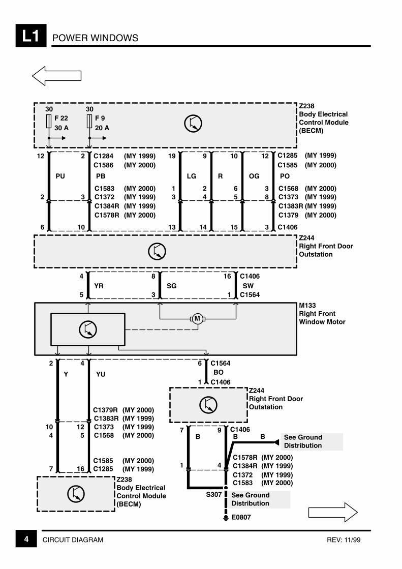
POWER WINDOWSL1
4 CIRCUIT DIAGRAM REV: 11/99
(MY 1999)
PO
12 C1285
Z238Body ElectricalControl Module(BECM)
3 C1406
Z244Right Front DoorOutstation
30F 2230 A
30F 920 A
12 C1373C1383R
8C1383RC1373
Z244Right Front DoorOutstation
OG
10
15
5
R
9
14
4
LG
19
13
3
PB
2 C1284
10
3C1384RC1372
PU
12
6
2
16 C140684SWSGYR
1 C156435
M133Right FrontWindow MotorM
42
YUY1 C1406
7
10
6 C1564BO
Z238Body ElectricalControl Module(BECM)
16 C1285
7B
9 C1406B
E0807
See GroundDistribution
S307
4C1372C1384R1
B See GroundDistribution
C1586 (MY 2000)(MY 1999)
C1583 (MY 2000)
(MY 1999)C1578R (MY 2000)
C1585 (MY 2000)(MY 1999)
3 C1568621(MY 1999)(MY 2000)
(MY 2000)(MY 1999)
C1379
(MY 1999)C1379R (MY 2000)
(MY 1999)C1568 (MY 2000)54
C1585 (MY 2000)(MY 1999)
C1578R
C1583
(MY 1999)(MY 2000)
(MY 1999)(MY 2000)

POWER WINDOWS L1
5CIRCUIT DIAGRAMREV: 08/99
Z238Body ElectricalControl Module(BECM)
30F 1230 A
3C1361C1385L
S
2
1 C1387L
C1362
YR
16
1
3 C0304L15
M116Left Rear WindowMotorM
42
YBBG
5
6
6 C0304L
Z238Body ElectricalControl Module(BECM)
2 C1286
C1286 10
SO
C1385LC1361
2
C1360C1386L
BO
7 C1286
4
C1386L
C1360
BK
14
5
RN
16
2
E0809
3C1362C1387L
See GroundDistribution
0
[1] [2]
C1291
C1385L
C1361
2 C0732L41
X188Left Rear WindowDoor Switch
[1] Up[2] Down
3 C0732L
B
S701L
See GroundDistributionS361
B
B

POWER WINDOWSL1
6 CIRCUIT DIAGRAM REV: 11/99
BO
8 C1285
Z238Body ElectricalControl Module(BECM)
30F 230 A
3C1370C1385R
3
C1386R
C1369
BK
17
5
RN
11
2
S
10
1 C1387R
C1371
YR
8
1
3 C0304R15
M124Right RearWindow MotorM
42
YBBG
5
6
6 C0304R
B
Z238Body ElectricalControl Module(BECM)
15 C1285
E0807
3C1371C1387R
See GroundDistribution
5
SO
C1385RC1370
2
C1369C1386R
0
[1] [2]
C1284
C1385L
C1370
2 C0732R41
X189Right RearWindow DoorSwitch
[1] Up[2] Down
3 C0732R
B
S701R
See GroundDistributionS307
B
C1585(MY 1999)(MY 2000)
C1586 (MY 2000)(MY 1999)
C1585 (MY 2000)(MY 1999)
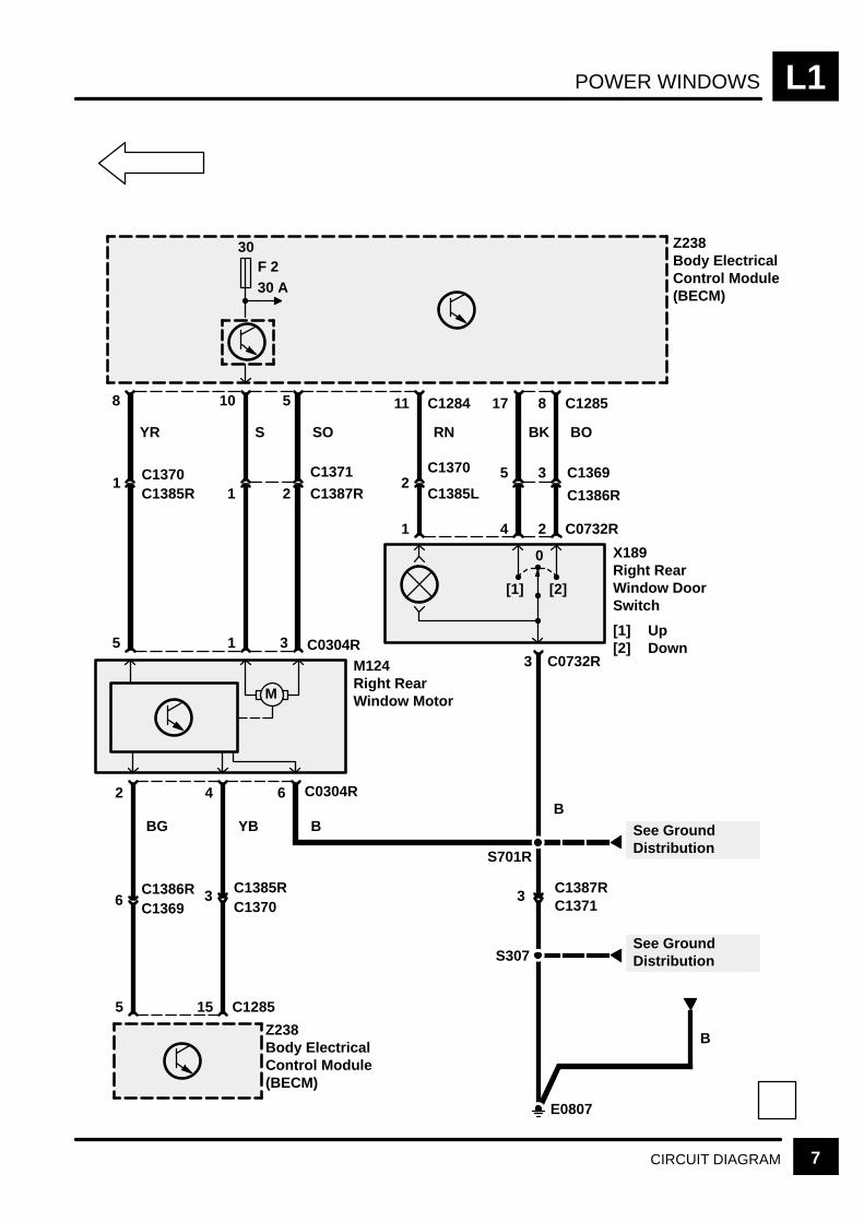
POWER WINDOWS L1
7CIRCUIT DIAGRAM
BO
8 C1285
Z238Body ElectricalControl Module(BECM)
30F 230 A
3C1370C1385R
3
C1386R
C1369
BK
17
5
RN
11
2
S
10
1 C1387R
C1371
YR
8
1
3 C0304R15
M124Right RearWindow MotorM
42
YBBG
5
6
6 C0304R
B
Z238Body ElectricalControl Module(BECM)
15 C1285
E0807
3C1371C1387R
See GroundDistribution
5
SO
C1385RC1370
2
C1369C1386R
0
[1] [2]
C1284
C1385L
C1370
2 C0732R41
X189Right RearWindow DoorSwitch
[1] Up[2] Down
3 C0732R
B
S701R
See GroundDistributionS307
B

SUNROOF L4
CIRCUIT OPERATION 1
CIRCUIT OPERATION
The sunroof can operate in either slide or tilt mode.To change from one mode to the other, the sunroofmust be in the closed position, the switch releasedand then repressed.
The sunroof functions will be active if the ignition isselected or for the first 45 seconds after it has beenswitched off provided that no door lock signal isreceived, in which case the timer will be cancelled.
The sunroof slide function will operate in one of twomodes: one touch, or dead man’s handle. One touchmode is initiated when the sunroof switch is operatedfor less than 400ms, dead man’s handle mode isinitiated when the sunroof switch is operated for400ms or more. Further operation of either sunroofswitch during the one shot mode will cause thesunroof to stop operation.
The sunroof tilt function will operate in deadman’shandle mode only.
There will be trap detection on sunroof close and ontilt close, but not on opening operations.
If a trap is detected whilst the sunroof is closing fromthe slide position, then the sunroof will back off 20cmor until the motor stalls. If a trap is detected whilstthe sunroof is closing from the tilt position then thesunroof will back off to the fully tilt open position.These conditions will also activate a message on theinstrument pack which will be accompanied by threeaudible beeps.
With the sunroof in the closed or partially tilted openposition, operation of the sunroof forward switch willcause the roof to operate in the tilt open direction.This will continue until the switch is released, or untila stall condition is detected.
If the sunroof back switch is operated while thesunroof is in the tilt open position, the roof willoperate in the tilt close direction. This will continueuntil the switch is released, a trap is detected or untilthe sunroof is in the closed position.
If the sunroof back switch is operated with thesunroof in the closed or partially open position, thesunroof will operate in the open direction. Thismovement will continue until the switch is released(unless in the one touch mode), the sunroof forwardswitch is operated, or a stall condition is detected.
With the sunroof in an open position, operation of thesunroof forward switch will cause the sunroof tooperate in the close direction. This will continue untilthe switch is released (unless in the one touchmode), the sunroof back switch is operated, a trap is
detected, or until the sunroof is in the fully closedposition.
The heated rear window will be inhibited for theduration of any sunroof operation.
Market Deviations:
USA/Canada: the system will only be active when the auxiliary or ignition feeds are on, or for the time between switching theignition feed off and opening either ofthe front doors.
Australia: the system will only be active when the ignition switch is in the auxiliary, the ignition or the crank position, or for 45 seconds after the key is removed from the ignition switch.
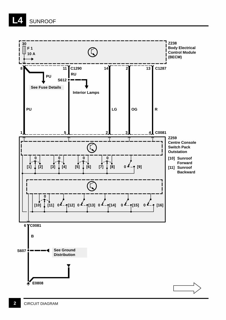
SUNROOFL4
2 CIRCUIT DIAGRAM
See GroundDistribution
30F 110 A
See Fuse Details
PU
PU
8 C129011
RU
S612
Interior Lamps
1 5
LG
14
2
OG
2
3
R
13
4
Z238Body ElectricalControl Module(BECM)
Z259Centre ConsoleSwitch PackOutstation
[10] SunroofForward
[11] SunroofBackward
C1287
C0081
0
[1] [2]
0
[3] [4]
0
[5] [6]
0
[7] [8] 0 [9]
0
[10] [11] 0 [12] 0 [13] 0 [14] 0 [15] 0 [16]
E0808
B
6 C0081
S607
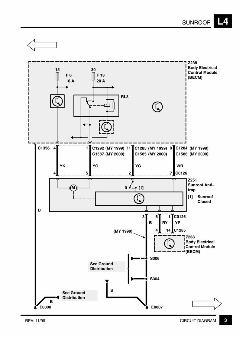
SUNROOF L4
3CIRCUIT DIAGRAMREV: 11/99
Z238Body ElectricalControl Module(BECM)
See GroundDistribution
RL3
30F 1320 A
1 C12924
YK YO
Z251Sunroof Anti–trap
[1] SunroofClosed
54
M
11 C1285
YG
2
9 C1284
WR
7 C0126
Z238Body ElectricalControl Module(BECM)
1 C0126
YP
14 C1285
6
RY
4
3
B
E0807E0808
BSee GroundDistribution
S306
S304
B
B
0 [1]
15F 610 A
C1356C1587 (MY 2000)
(MY 1999)C1585 (MY 2000)
(MY 1999)C1586 (MY 2000)
(MY 1999)
(MY 1999)

SUNROOFL4
4 CIRCUIT DIAGRAM
See GroundDistribution
RL3
30F 1320 A
Z238Body ElectricalControl Module(BECM)
1 C12924YK YO
Z251Sunroof Anti–trap
[1] SunroofClosed
54
M
11 C1285YG
2
9 C1284WR
7 C0126
Z238Body ElectricalControl Module(BECM)
1 C0126
YP
14 C1285
6
RY
4
3
B
E0807E0808
BSee GroundDistribution
S306
S304
B
B
0 [1]
15F 610 A
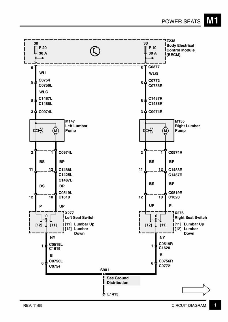
POWER SEATS M1
1CIRCUIT DIAGRAMREV: 11/99
30F 2030 A
6
5 C0754C0756L
WU
8 C1487LC1488L
3 C0974L
M
M147Left LumbarPump
2
12
11
BS
BS
P
1 C0974L
10C0519L
12 C1488LC1425L
BP
BP
UP
[12] [11]
X277Left Seat Switch
[11] Lumbar Up[12] Lumbar
Down
0
1 C0519L
NY
6 C0756LC0754
B
30F 1030 A
5 C0877
5 C0772C0756R
WLG
8 C1487RC1488R
3 C0974R
M
2
12
11
BS
BS
UP
1 C0974R
10C0519R
12 C1488RC1487R
BP
BP
P
[12] [11]
0
1 C0519R
NY
6C0772
B
Z238Body ElectricalControl Module(BECM)
S901
E1413
See GroundDistribution
WLG
X276Right Seat Switch
[11] Lumbar Up[12] Lumbar
Down
M155Right LumbarPump
C0756R
C1487L
C1619
C1619
C1620
C1620

POWER SEATS (LEFT)M1
2 CIRCUIT DIAGRAM REV: 11/99
30F 2030 A
1
9 C0877
B
M1-4
Z238Body ElectricalControl Module(BECM)
85 C0154L
7 C0754C0756L
87
W BY
K213Left Non–Memory SeatPower Relay 1
86 C0154L30
A
M1-3
85 C0157L87
WBY
K215Left Non–Memory SeatPower Relay 2
86 C0157L30WO WO
2C0756LC0754
WO WO
8 7 C0877
Z238Body ElectricalControl Module(BECM)
W WP
Power Seats(Left)
With New SeatHeightAdjustment
Without NewSeat HeightAdjustment
W
C0877 With New SeatHeight Adjustment
3
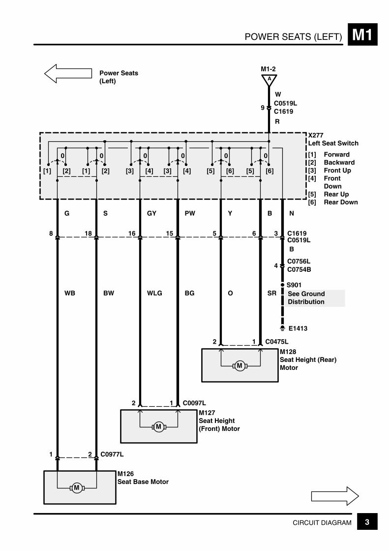
POWER SEATS (LEFT) M1
3CIRCUIT DIAGRAM
X277Left Seat Switch
[1] Forward[2] Backward[3] Front Up[4] Front
Down[5] Rear Up[6] Rear Down
G
See GroundDistribution
0
[2][1]
0
[2][1]
0
[4][3]
0
[4][3]
0
[6][5]
0
[6][5]
8
1 C0097L
WB
S
18
BW
GY
16
WLG
PW
15
BG
Y
5
O
B
6
SR
N
3 C1619
B
M
1 2 C0977L
M126Seat Base Motor
M
M127Seat Height(Front) Motor
2
1 C0475L
M
M128Seat Height (Rear)Motor
2
4C0756LC0754B
S901
E1413
A
M1-2
R
W
9C0519LC1619
Power Seats(Left)
C0519L
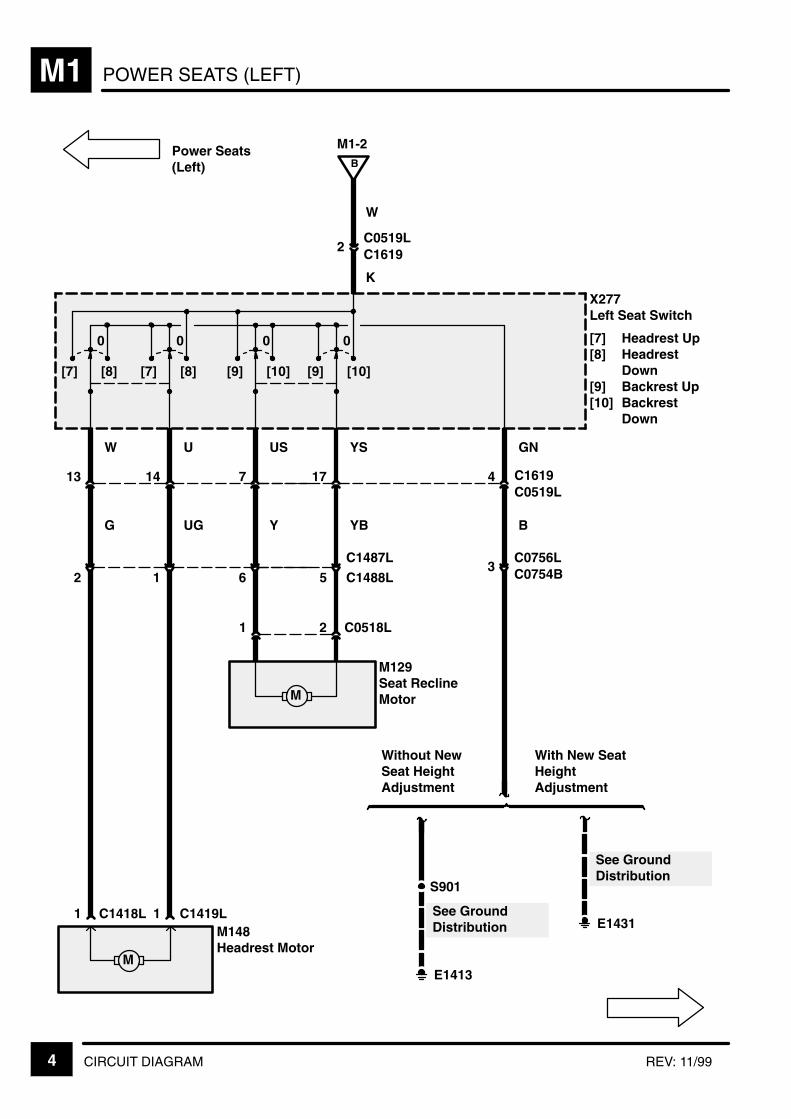
POWER SEATS (LEFT)M1
4 CIRCUIT DIAGRAM REV: 11/99
X277Left Seat Switch
[7] Headrest Up[8] Headrest
Down[9] Backrest Up[10] Backrest
Down
W
See GroundDistribution
0
[8][7]
0
[8][7]
0
[10][9]
0
[10][9]
13
G
U
14
UG
US
7
Y
YS
17
YB
GN
4 C1619
B
M
1 2 C0518L
M129Seat ReclineMotor
1 C1419L
M
M148Headrest Motor
1 C1418L
3C0756LC0754B
E1413
B
M1-2
K
W
2C0519LC1619
5
C1487L
C1488L612
Power Seats(Left)
C0519L
S901
See GroundDistribution
E1431
Without NewSeat HeightAdjustment
With New SeatHeightAdjustment
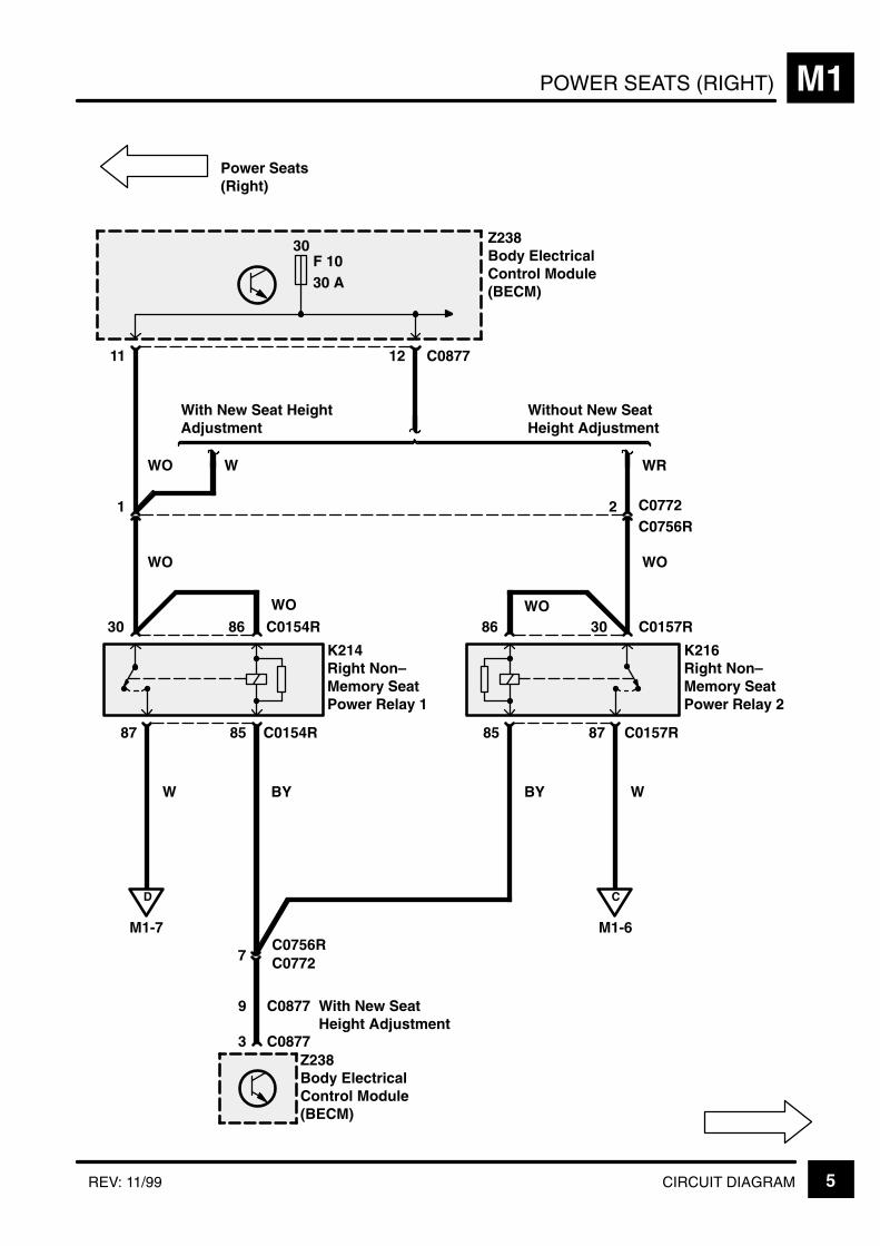
POWER SEATS (RIGHT) M1
5CIRCUIT DIAGRAMREV: 11/99
30F 1030 A
1
3 C0877
D
M1-7
Z238Body ElectricalControl Module(BECM)
85 C0154R
7 C0772C0756R
87
W BY
K214Right Non–Memory SeatPower Relay 1
86 C0154R30
C
M1-6
85 C0157R87
WBY
K216Right Non–Memory SeatPower Relay 2
86 C0157R30WO WO
2C0756RC0772
WO WO
11 12 C0877
Z238Body ElectricalControl Module(BECM)
WO WR
Power Seats(Right)
With New Seat HeightAdjustment
Without New SeatHeight Adjustment
W
C0877 With New SeatHeight Adjustment
9

POWER SEATS (RIGHT)M1
6 CIRCUIT DIAGRAM
S
See GroundDistribution
0
[2][1]
0
[2][1]
0
[4][3]
0
[4][3]
0
[6][5]
0
[6][5]
8
1 C0097R
WB
G
18
BW
Y
16
WLG
B
15
BG
YG
5
O
PW
6
SR
N
3 C1620
B
M
1 2 C0977R
M126Seat Base Motor
M
M127Seat Height(Front) Motor
2
1 C0475R
M
M128Seat Height (Rear)Motor
2
4C0756RC0772
S901
E1413
C
M1-5
R
W
9C0519RC1620
Power Seats(Right)
X276Right Seat Switch
[1] Forward[2] Backward[3] Front Up[4] Front Down[5] Rear Up[6] Rear Down
C0519R
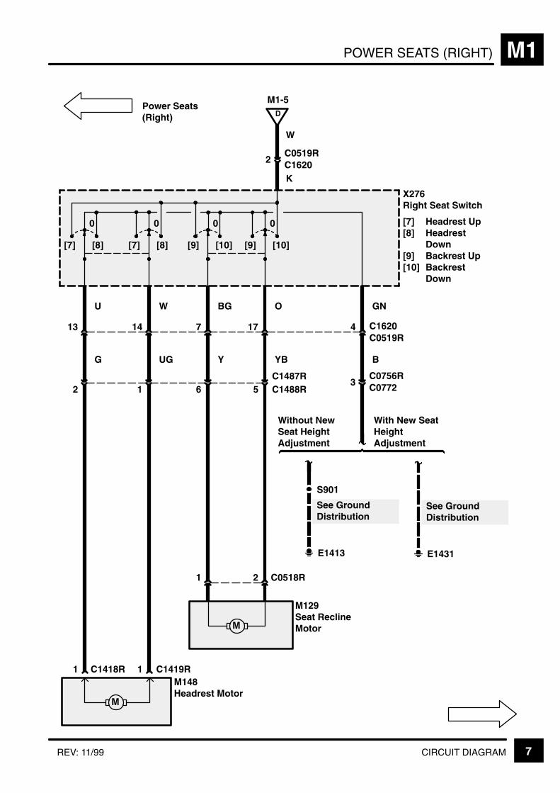
POWER SEATS (RIGHT) M1
7CIRCUIT DIAGRAMREV: 11/99
X276Right Seat Switch
[7] Headrest Up[8] Headrest
Down[9] Backrest Up[10] Backrest
Down
U
See GroundDistribution
0
[8][7]
0
[8][7]
0
[10][9]
0
[10][9]
13
G
W
14
UG
BG
7
Y
O
17
YB
GN
4 C1620
B
M
1 2 C0518R
M129Seat ReclineMotor
1 C1419R
M
M148Headrest Motor
1 C1418R
3C0756RC0772
E1431
D
M1-5
K
W
2C0519RC1620
5C1487RC1488R612
Power Seats(Right)
C0519R
See GroundDistribution
E1413
S901
Without NewSeat HeightAdjustment
With New SeatHeightAdjustment

POWER SEATS (RIGHT)M1
8 CIRCUIT DIAGRAM REV: 11/99
Seat HeightAdjuster
30F 2030 A
2 C1432
1 C1432
8 7 C0877
Z238Body ElectricalControl Module(BECM)
W WP
2 C1433X332Right Front SeatHeight Adjuster
1 C1433
X331Left Front SeatHeight Adjuster
E1431
See GroundDistribution
See GroundDistribution

POWER MIRRORS M3
1CIRCUIT DIAGRAM
See GroundDistribution
30F 110 A
See Fuse Details
PU
PU
8 C129011
RU
S612
Interior Lamps
1 5
LG
14
2
OG
2
3
R
13
4
Z238Body ElectricalControl Module(BECM)
Z259Centre ConsoleSwitch PackOutstation
[12] Mirror Down[13] Mirror Up[14] Mirror Right[15] Mirror Left[16] Mirror
Select
C1287
C0081
0
[1] [2]
0
[3] [4]
0
[5] [6]
0
[7] [8] 0 [9]
0
[10] [11] 0 [12] 0 [13] 0 [14] 0 [15] 0 [16]
E0808
B
6 C0081
S607

POWER MIRRORSM3
2 CIRCUIT DIAGRAM REV: 11/99
M
30F 2230 A
8 C1364
S361
1 C1563L42
M
35
6 C1563L
[1]
E0809
See GroundDistribution
GUSRY
4C1384LC13651
B
M115Left MirrorActuator
[1] Left/Right[2] Up/Down
12 C1407L
B
Z243Left Front DoorOutstation
Z243Left Front DoorOutstation
BB
See GroundDistribution
3 C1407L87219 C15807
3 C1580
PO8 C1286
C1383L5
15
OG9
4
14
R10
3
13
LG1
Z238Body ElectricalControl Module(BECM)
3 C1365
10
PB8 C1291
C1384L2
6
PU7
30F 920 A
15 C1289
Z106Generator
D+
NY
25C0162C0448
25C0203C0448
S573 Starting andCharging
DieselPetrol
[2]
C0185C0226D
PetrolDiesel
PowerDistribution
NYS137
C1368
C1578L (MY 2000)(MY 1999)
3 C1366621
C1379L (MY 2000)(MY 1999)
(MY 1999)(MY 2000)
(MY 1999)(MY 2000)
C1578L
C1368
(MY 2000)(MY 1999)(MY 1999)(MY 2000)
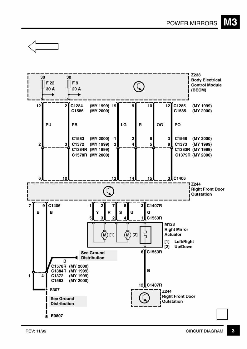
POWER MIRRORS M3
3CIRCUIT DIAGRAMREV: 11/99
M
30F 2230 A
8 C1373
S307
1 C1563R42
M
35
6 C1563R
[1]
E0807
See GroundDistribution
GUSRY
4C1384RC13721
B
M123Right MirrorActuator
[1] Left/Right[2] Up/Down
12 C1407R
B
Z244Right Front DoorOutstation
Z244Right Front DoorOutstation
BB
See GroundDistribution
3 C1407R87219 C14067
3 C1406
PO
12 C1285
C1383R5
15
OG
10
4
14
R
9
3
13
LG
19
Z238Body ElectricalControl Module(BECM)
3 C1372
10
PB
2 C1284
C1384R2
6
PU
12
30F 920 A
[2]
C1586 (MY 2000)(MY 1999)
C1585 (MY 2000)(MY 1999)
C1583(MY 1999)(MY 2000) 3621 C1568
(MY 1999)(MY 2000)
(MY 1999)C1578R C1379R (MY 2000)(MY 2000)
(MY 1999)
C1578R (MY 2000)
C1583
(MY 1999)(MY 1999)(MY 2000)

KEY INFORMATIONi
!"
#$ % &'( ' )
*$ % &'( + %
,# % &'( ' )
% &'( ' )
-
*, !+
!
+ ' '
+ .) . . '
/+ +0 .
' /'+0
"% ) '
+ ) . % .
+ +- %
. )
(
.
!"
. ' % 1(
2 + " .
' ) '
2 +' 3 .
.' % '
2 .) % '
2 4 .' % '-
&+
+ )
+ /0 .
+ ' %
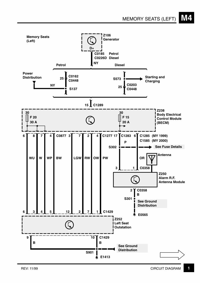
MEMORY SEATS (LEFT) M4
1CIRCUIT DIAGRAMREV: 11/99
C1283 6
4 5
17
15 C1289
30F 1520 A
Z106Generator
Petrol Diesel
25C0162
25C0203
S573
Z238Body ElectricalControl Module(BECM)
E1413
10 C1429
S901
Z252Left SeatOutstation
See GroundDistribution
B
S302 See Fuse DetailsP
9
B
2 C0358
Z250Alarm R.F.Antenna Module
S301See GroundDistribution
B
3
6 C0877
30F 2030 A
WU
6
8
W
3
7
WP
4
BW
E0565
C0448
C0448
7 1
3 C1277
LGW
12
7
RW
2
2
OW
4
PW
C1429
NY
Starting andCharging
C1285
OR
C03581
Antenna
D+
30F 1520 A
Memory Seats(Left)
C0185C0226D
PetrolDiesel
PowerDistribution
NYS137
C1585 (MY 2000)(MY 1999)
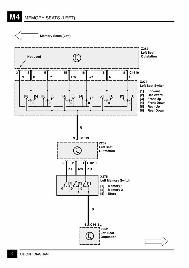
MEMORY SEATS (LEFT)M4
2 CIRCUIT DIAGRAM
Z252Left SeatOutstation
9
C161916S
8G
C1619
Z252Left SeatOutstation
X277Left Seat Switch
[1] Forward[2] Backward[3] Front Up[4] Front Down[5] Rear Up[6] Rear Down
5PW
15GY
3N
6Y
Memory Seats (Left)
[1][2][1][2][3][4][3][4][5][6][5][6]
000000
Z252Left SeatOutstation
KW
4 C1618L
B
[2]
0
[1]
0
12
X278Left Memory Switch
[1] Memory 1[2] Memory 2[5] Store
C1618L
KR
B18
R
Not used
KY
[5]
0
5

MEMORY SEATS (LEFT) M4
3CIRCUIT DIAGRAM
GN
Z252Left SeatOutstation
2
C16197
U
13
W
C1619
Z252Left SeatOutstation
X277Left Seat Switch
[7] Headrest Up[8] Headrest
Down[9] Backrest Up[10] Backrest
Down[11] Lumbar Up[12] Lumbar
Down
YS
17
US
10
Memory Seats (Left)
[7][8][7][8][9][10][9][10][11][12]
0000
UP
14
K
Not used
1
NY
12
P
4
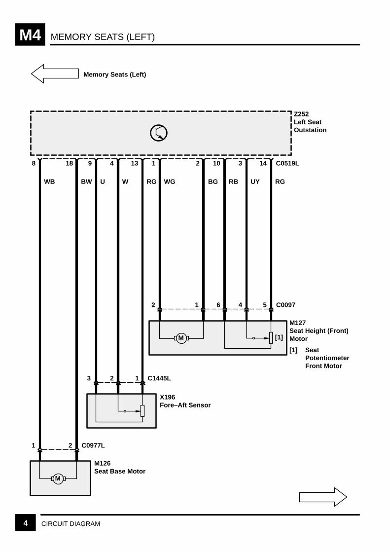
MEMORY SEATS (LEFT)M4
4 CIRCUIT DIAGRAM
RGUYRBWU
M127Seat Height (Front)Motor
[1] SeatPotentiometerFront Motor
1
C0519L2 14
Z252Left SeatOutstation
WG
1
BG
Memory Seats (Left)
2
M
5 C0097
3
4
10
6
M126Seat Base Motor
18 13
RGWB
8
BW
M
X196Fore–Aft Sensor
C1445L
49
2 C0977L1
123
[1]

MEMORY SEATS (LEFT) M4
5CIRCUIT DIAGRAM
RG BSWLGBPURRB
C1425L11
Z252Left SeatOutstation
Memory Seats (Left)
M147Left LumbarPump
2 C0974L
8
3
12
1
6 15
WY
17
BY
M128Seat Height (Rear)Motor
[1] SeatPotentiometerRear Motor
C0475L
1211
M
C0519L
54612
M [1]
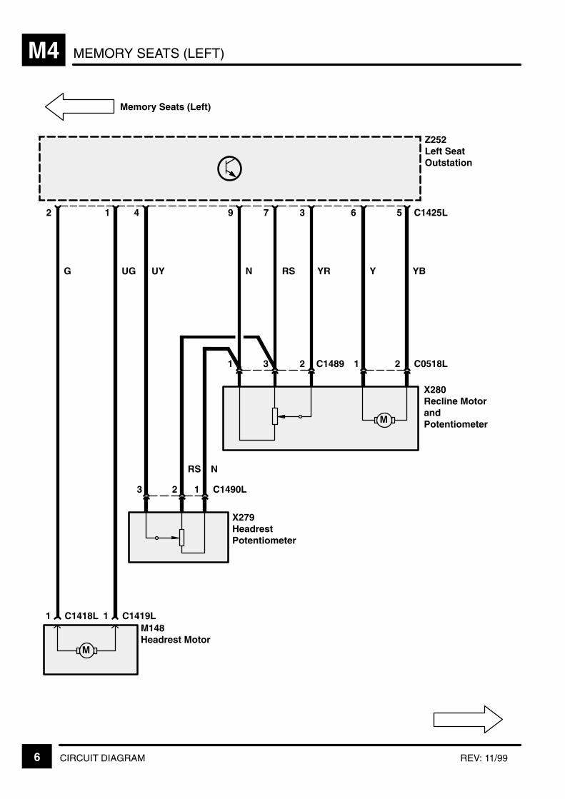
MEMORY SEATS (LEFT)M4
6 CIRCUIT DIAGRAM REV: 11/99
YR Y
C1489
C1418L
N
RS
RS
UY
5
Z252Left SeatOutstation
Memory Seats (Left)
X280Recline MotorandPotentiometer
3
23
1
G
2
UG
X279HeadrestPotentiometer
C1490L
74
123
M148Headrest Motor
1 C1419L1
M
YB
C1425L
2 C0518L1
M
1
9 6
N

MEMORY SEATS (RIGHT) M4
7CIRCUIT DIAGRAMREV: 11/99
O PRLGBOWRWO
C1277 6
4 5
17
15 C1289
30F 1520 A
Z106Generator
Petrol Diesel
25C0162
25C0203
S573
Z238Body ElectricalControl Module(BECM)
E1413
10 C1430
S901
Z258Right SeatOutstation
See GroundDistribution
B
S302 See Fuse Details
P
9
B
2 C0358
Z250Alarm R.F.Antenna Module
S301See GroundDistribution
B
3
5 C0877
30F 1030 A
WLG
6
11
3
12 10
E0565
C0448
C0448
7 1
6
12
1
2
5 8
C1430
NY
Starting andCharging
C1285
OR
C03581
Antenna
D+
30F 1520 A
Memory Seats(Right)
C0185C0226D
PetrolDiesel
PowerDistribution
NYS137
C1585 (MY 2000)(MY 1999)

MEMORY SEATS (RIGHT)M4
8 CIRCUIT DIAGRAM
Z258Right SeatOutstation
9
C162016G
8S
C1620
Z258Right SeatOutstation
X276Right Seat Switch
[1] Forward[2] Backward[3] Front Up[4] Front Down[5] Rear Up[6] Rear Down
5B
15Y
3N
6YG
Memory Seats (Right)
[1][2][1][2][3][4][3][4][5][6][5][6]
000000
Z258Right SeatOutstation
KW
4 C1618R
B
[2]
0
[1]
0
12
X317Right Memory Switch
[1] Memory 1[2] Memory 2[5] Store
C1618RKR
PW18
R
Not used
KY
[5]
0
5

MEMORY SEATS (RIGHT) M4
9CIRCUIT DIAGRAM
GN
Z258Right SeatOutstation
2
C16207
W
13
U
C1620
Z258Right SeatOutstation
X276Right Seat Switch
[7] Headrest Up[8] Headrest
Down[9] Backrest Up[10] Backrest
Down[11] Lumbar Up[12] Lumbar
Down
O
1710
Memory Seats(Right)
[7][8][7][8][9][10][9][10][11][12]
0000
P
14
K
Not used
1
NY
12
UP
4
BG
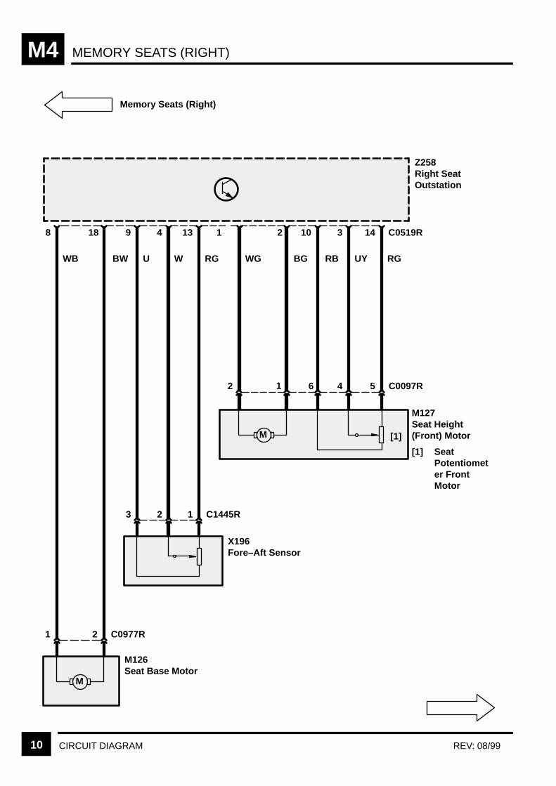
MEMORY SEATS (RIGHT)M4
10 CIRCUIT DIAGRAM REV: 08/99
RGUYRBWU
M127Seat Height(Front) Motor
[1] SeatPotentiometer FrontMotor
C0519R2 14
Z258Right SeatOutstation
WG
1
BG
Memory Seats (Right)
M
5 C0097R
3
4
10
6
M126Seat Base Motor
18 13
RGWB
8
BW
M
X196Fore–Aft Sensor
C1445R
49
2 C0977R1
123
2 1
[1]
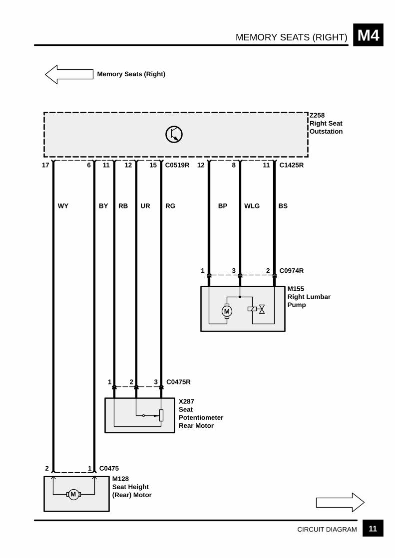
MEMORY SEATS (RIGHT) M4
11CIRCUIT DIAGRAM
RG BSWLGBPURRB
C1425R11
Z258Right SeatOutstation
Memory Seats (Right)
M155Right LumbarPump
2 C0974R
8
3
12
1
6 15
WY
17
BY
X287SeatPotentiometerRear Motor
C0475R
1211
M
C0519R
321
M128Seat Height(Rear) Motor
1 C04752
M

MEMORY SEATS (RIGHT)M4
12 CIRCUIT DIAGRAM
C1489
C1418R
N
YRRS
RS
UY
5
Z258Right SeatOutstation
Memory Seats (Right)
X280Recline MotorandPotentiometer
3
23
1
G
2
UG
X279HeadrestPotentiometer
C1490R
74
123
M148Headrest Motor
1 C1419R1
M
YB
C1425R
2 C0518R1
M
1
9 6
N Y
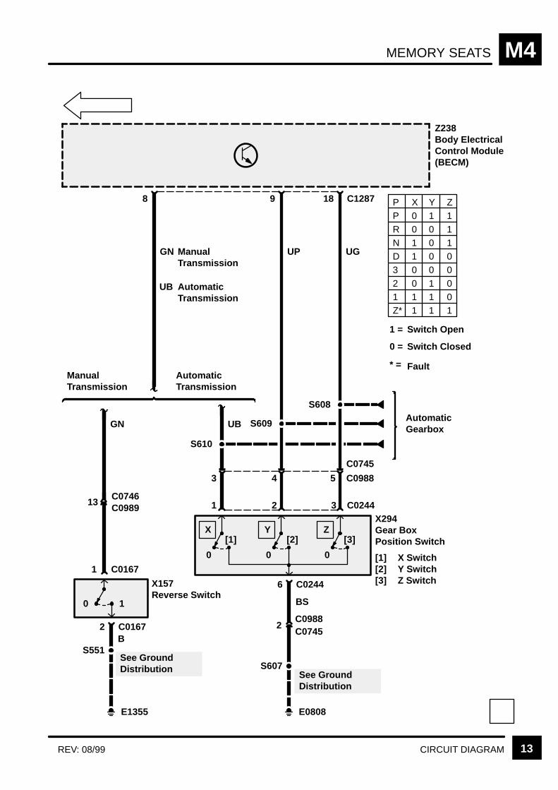
MEMORY SEATS M4
13CIRCUIT DIAGRAMREV: 08/99
6 C0244
UGUP
C128718
Z238Body ElectricalControl Module(BECM)
9
GN
8
P 0 1 1R 0 0 1N 1 0 1D 1 0 03 0 0 0
2 0 1 01 1 1 0Z* 1 1 1
X Y Z
0 1
2 C0167
X157Reverse Switch
S551See GroundDistribution
B
GN
C01671
13C0746C0989
ManualTransmission
AutomaticTransmission
UB
3
S610
AutomaticGearbox
[1]
0
[2]
0
[3]
0
5
C0745
C09884
C0244321
S609
S608
UB
X Y Z
S607See GroundDistribution
BS
E0808
2C0988C0745
X294Gear BoxPosition Switch
[1] X Switch[2] Y Switch[3] Z Switch
AutomaticTransmission
ManualTransmission
E1355
P
1 = Switch Open
Switch Closed
Fault
0 =
* =


HEATED SEATS M6
CIRCUIT OPERATION 1REV: 11/2000
CIRCUIT OPERATION
Driver and passenger seat heaters are temperatureregulated by a thermal switch located in each seat.The seat heaters will only operate while the engine isrunning and, once selected, remain energised untilselected off or until the ignition is turned off.
Seat heater activation is initiated by pressing theappropriate switch on the HEVAC ECU. Provided theengine is running, the HEVAC ECU transfers therequest to the BeCM by switching the applicableoutput from Vbatt to ground for the duration that theswitch is pressed. On receipt of the seat heaterrequest, the BeCM switches the appropriate seatheater output from ground to Vbatt. To preventcurrent overload, the BeCM inhibits the seat heateroutput if both rear windows and the sunroof areoperated together, or if an uninitialised rear windowor sunroof are operated.
The seat heater power output from the BeCMpasses through the thermal switch and the heatingelements, in the seat cushion and seat squab, toground. The temperature of the heating elements isregulated by the opening and closing of the thermalswitch.
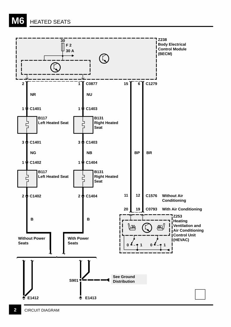
HEATED SEATSM6
2 CIRCUIT DIAGRAM
E1412 E1413
S901
With PowerSeats
See GroundDistribution
Without PowerSeats
B117Left Heated Seat
2 C1402
1 C1402
B131Right HeatedSeat
2 C1404
1 C1404
B117Left Heated Seat
3 C1401
1 C1401
B131Right HeatedSeat
3 C1403
1 C1403
NR
NG
B
NU
NB
B
2 1 C0877
BP
15
Z253HeatingVentilation andAir ConditioningControl Unit(HEVAC)
Z238Body ElectricalControl Module(BECM)
0 10 1
20
30F 230 A
BR
6 C1279
19 C0793
12 C1576 Without AirConditioning
With Air Conditioning
11
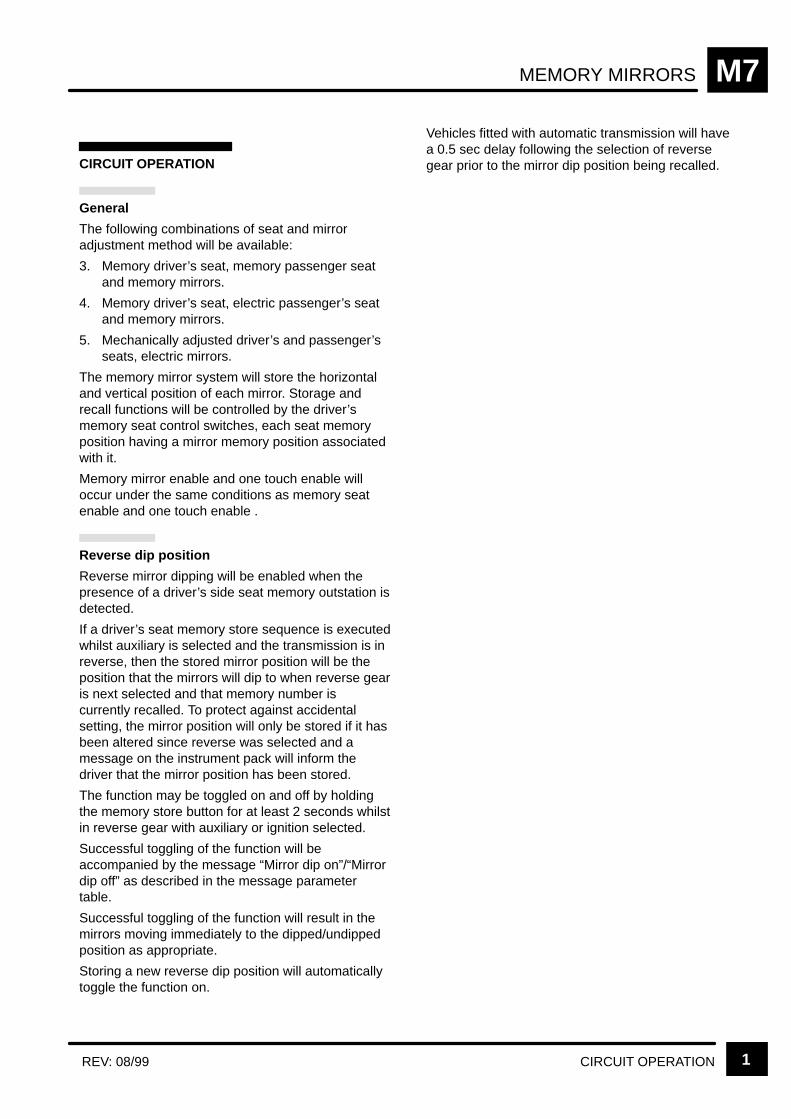
MEMORY MIRRORS M7
CIRCUIT OPERATION 1REV: 08/99
CIRCUIT OPERATION
General
The following combinations of seat and mirroradjustment method will be available:
3. Memory driver’s seat, memory passenger seatand memory mirrors.
4. Memory driver’s seat, electric passenger’s seatand memory mirrors.
5. Mechanically adjusted driver’s and passenger’sseats, electric mirrors.
The memory mirror system will store the horizontaland vertical position of each mirror. Storage andrecall functions will be controlled by the driver’smemory seat control switches, each seat memoryposition having a mirror memory position associatedwith it.
Memory mirror enable and one touch enable willoccur under the same conditions as memory seatenable and one touch enable .
Reverse dip position
Reverse mirror dipping will be enabled when thepresence of a driver’s side seat memory outstation isdetected.
If a driver’s seat memory store sequence is executedwhilst auxiliary is selected and the transmission is inreverse, then the stored mirror position will be theposition that the mirrors will dip to when reverse gearis next selected and that memory number iscurrently recalled. To protect against accidentalsetting, the mirror position will only be stored if it hasbeen altered since reverse was selected and amessage on the instrument pack will inform thedriver that the mirror position has been stored.
The function may be toggled on and off by holdingthe memory store button for at least 2 seconds whilstin reverse gear with auxiliary or ignition selected.
Successful toggling of the function will beaccompanied by the message “Mirror dip on”/“Mirrordip off” as described in the message parametertable.
Successful toggling of the function will result in themirrors moving immediately to the dipped/undippedposition as appropriate.
Storing a new reverse dip position will automaticallytoggle the function on.
Vehicles fitted with automatic transmission will havea 0.5 sec delay following the selection of reversegear prior to the mirror dip position being recalled.
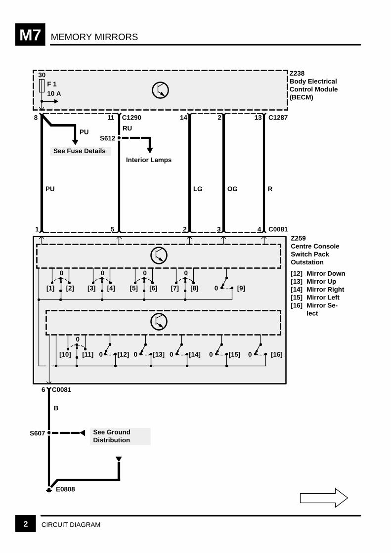
MEMORY MIRRORSM7
2 CIRCUIT DIAGRAM
See GroundDistribution
30F 110 A
See Fuse Details
PU
PU
8 C129011
RU
S612
Interior Lamps
1 5
LG
14
2
OG
2
3
R
13
4
Z238Body ElectricalControl Module(BECM)
Z259Centre ConsoleSwitch PackOutstation
[12] Mirror Down[13] Mirror Up[14] Mirror Right[15] Mirror Left[16] Mirror Se-
lect
C1287
C0081
0
[1] [2]
0
[3] [4]
0
[5] [6]
0
[7] [8] 0 [9]
0
[10] [11] 0 [12] 0 [13] 0 [14] 0 [15] 0 [16]
E0808
B
6 C0081
S607

MEMORY MIRRORS M7
3CIRCUIT DIAGRAMREV: 08/99
8
Z238Body ElectricalControl Module(BECM)
2 C0167
9 18 C1287
AutomaticTransmission
ManualTransmission
13C0746
0 1
X157Reverse Switch
S551
E1355
UP UG
S608
S609
S610
UB
6 C0244
0 [1]
X
1
0 [2]
Y
2
0 [3]
Z
3 C0244
GN
B
BS
S607
E0808
C0989
1 C0167
See GroundDistribution
See GroundDistribution
X294Gear Box PositionSwitch
[1] X Switch[2] Y Switch[3] Z Switch
P 0 1 1R 0 0 1N 1 0 1D 1 0 03 0 0 0
2 0 1 01 1 1 0Z* 1 1 1
X Y Z
AutomaticGearbox
GN
UB AutomaticTransmission
ManualTransmission
1 =
0 =
* =
Switch Open
Switch Closed
Fault
3 5
C0745
C09884
2C0988C0745
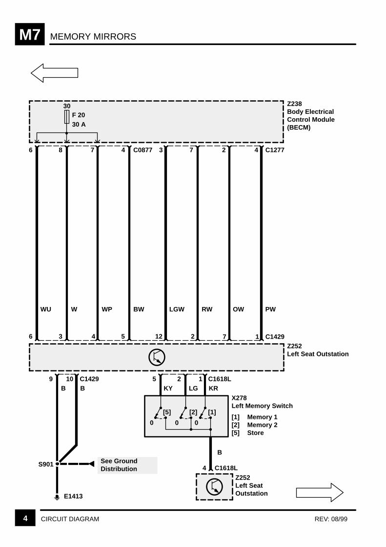
MEMORY MIRRORSM7
4 CIRCUIT DIAGRAM REV: 08/99
KY
4 C1277
[5]
0
4 C1618L
B
5
Z252Left SeatOutstation
[2]
0
[1]
0
12
4
PW
36 125
LGX278Left Memory Switch
[1] Memory 1[2] Memory 2[5] Store
Z252Left Seat Outstation
B9
E1413
B10
S901 See GroundDistribution
C1429 C1618L
172
OWRWLGWBWWPWWU
C1429
30F 2030 A
4 C0877
KR
273786
Z238Body ElectricalControl Module(BECM)
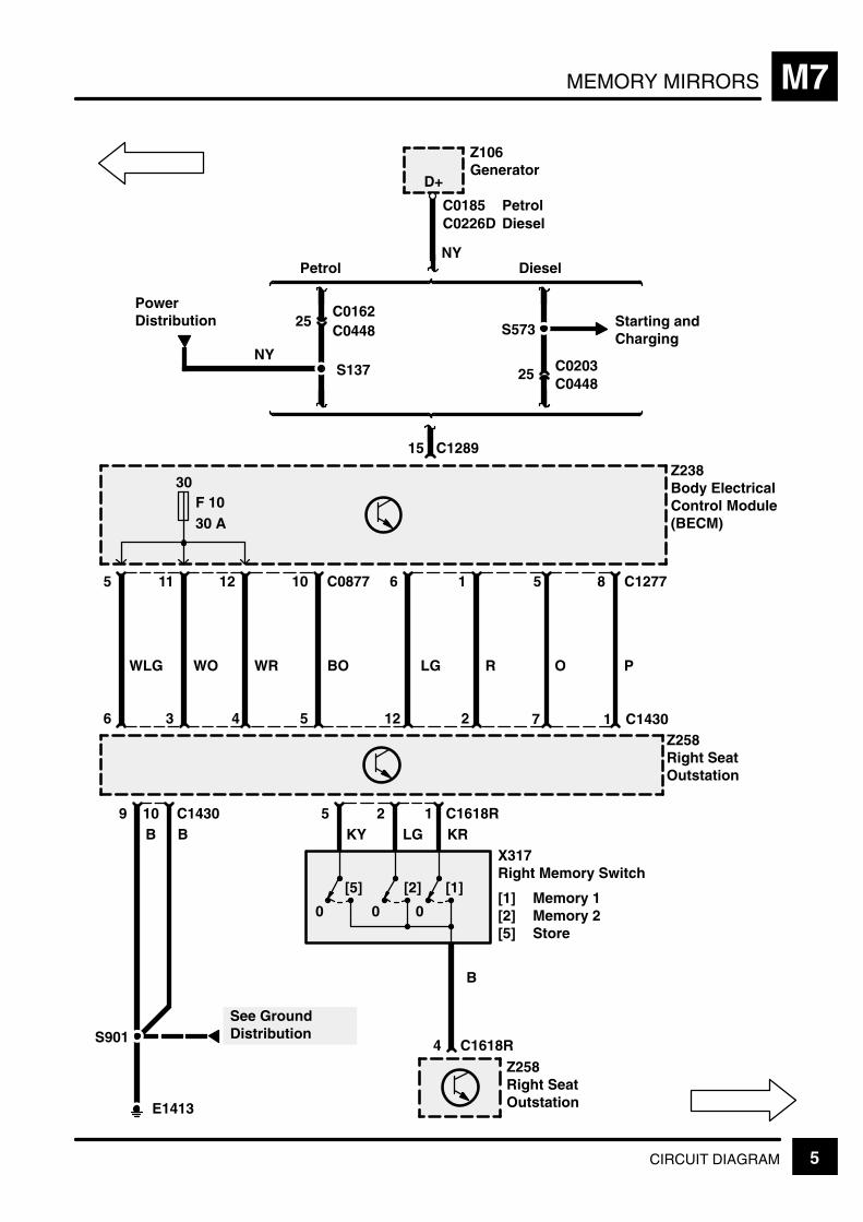
MEMORY MIRRORS M7
5CIRCUIT DIAGRAM
KY
8 C1277
[5]
0
4 C1618R
B
5
Z258Right SeatOutstation
[2]
0
[1]
0
12
4
P
36 125
LG
Z258Right SeatOutstation
B9
E1413
B10
S901See GroundDistribution
C1430 C1618R
172
ORLGBOWRWOWLG
C1430
Z238Body ElectricalControl Module(BECM)
30F 1030 A
10 C0877
KR
51612115
15 C1289
Z106Generator
D+
NY
25C0162C0448
25 C0203C0448
S573 Starting andCharging
DieselPetrol
X317Right Memory Switch
[1] Memory 1[2] Memory 2[5] Store
C0185C0226D
PetrolDiesel
PowerDistribution
NYS137

MEMORY MIRRORSM7
6 CIRCUIT DIAGRAM REV: 11/99
R
M
30F 2230 A
S351
142
M
35
6
[1]
E0809
See GroundDistribution
GUSY
4 C1365C1369
1
B
M152Left Memory Mirror
[1] Left/Right[2] Up/Down[3] Vertical
Potentiometer[4] Horizontal
Potentiometer
12
B
Z243Left Front DoorOutstation
Z243Left Front DoorOutstation
BB
See GroundDistribution
387219 C15807
Z238Body ElectricalControl Module(BECM)
30F 920 A
12 C0319L
P
C1407L
[2]
13
10 C0319L
W
5 C1407L
BR
10
11
O
6 11
[3] [4]
(MY 1999)
PO
8 C1286
3 C1580
8C1383LC1364
OG
9
15
5
R
10
14
4
LG
1
13
3
PB
8 C1291
10
3C1384LC1365
C1578 (MY 2000)(MY 1999)
C1368 (MY 2000) 3 C1366621(MY 1999)
(MY 2000)(MY 1999)
(MY 2000)
C1379L
C1578LC1384L (MY 1999)
(MY 2000)
(MY 1999)(MY 2000)

MEMORY MIRRORS M7
7CIRCUIT DIAGRAMREV: 11/99
R
M
30F 2230 A
S351
142
M
35
6
[1]
E0807
See GroundDistribution
GUSY
4
C1578RC1384R
1
B
M151Right MemoryMirror
[1] Left/Right[2] Up/Down[3] Vertical
Potentiometer[4] Horizontal
Potentiometer
12
B
Z244Right Front DoorOutstation
Z244Right Front DoorOutstation
BB
See GroundDistribution
387219 C14067
Z238Body ElectricalControl Module(BECM)
30F 920 A
12 C0319R
P
C1407R
[2]
13
10 C0319R
W
5 C1407R
BR
10
11
O
6 11
[3] [4]
(MY 1999)
PO
12 C1285
3 C1406
8C1383RC1373
OG
10
15
5
R
9
14
4
LG
19
13
3
PB
2 C1284
10
3C1384RC1372
PU
12
6
2
C1586 (MY 2000)(MY 1999)
C1583 (MY 2000)
(MY 1999)C1578R (MY 2000)
C1585 (MY 2000)(MY 1999)
3 C1568621(MY 1999)(MY 2000)
(MY 2000)(MY 1999)
C1379R
C1372C1583
(MY 1999)(MY 2000)
(MY 1999)(MY 2000)
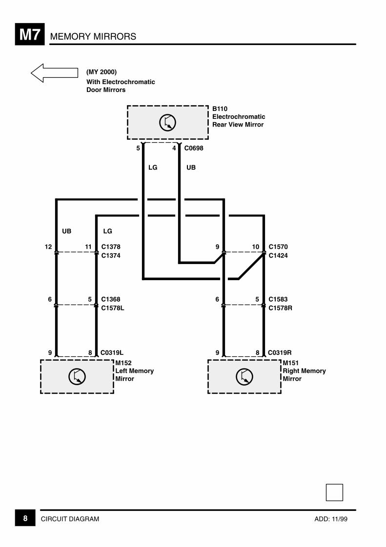
MEMORY MIRRORSM7
8 CIRCUIT DIAGRAM ADD: 11/99
5C1578LC1368
LGUB
9
6
M152Left MemoryMirror
8 C0319L
11C1374C137812
5C1578RC1583
9
6
M151Right MemoryMirror
8 C0319R
10C1424C15709
B110ElectrochromaticRear View Mirror
4 C06985
LG UB
(MY 2000)
With ElectrochromaticDoor Mirrors

Supplementary Restraint System (SRS) N1
CIRCUIT OPERATION 1
CIRCUIT OPERATION
The Supplementary Restraint System (SRS)provides enhanced passive protection for the driverand front passenger in the event of a seriouscollision.
SRS Diagnostic Control Unit (Z151)
The power supply to the SRS Diagnostic ControlUnit (Z151) is fed via fuse 23 in the enginecompartment fuse box, when the ignition is turned toposition II. The SRS warning lamp in the InstrumentCluster (Z142) will be illuminated for a period ofapproximately 5 seconds after the ignition switch istuned to position II, while the SRS Diagnostic ControlUnit (Z151) performs a system integrity check. If afault should be detected, the relevant fault code willbe stored in the SRS Diagnostic Control Unit (Z151)memory and the warning lamp will remain illuminatedfor the remainder of the ignition cycle.
The SRS Diagnostic Control Unit (Z151) monitorsthe following components during the power–upphase and for the complete ignition cycle.
Accelerometers
Safing sensor
SRS Diagnostic Control Unit (Z151) micropro-cessor
Front airbags
Side airbags
Seatbelt pre–tensioners
Front crash–sensors (NAS only)
SRS warning lamps
The SRS Diagnostic Control Unit (Z151) contains amain sensor which is the primary device fordetecting the presence of a crash condition, and asafing sensor which is used for confirmation of acrash condition. This confirmation signal is providedto prevent unintentional detonation of SRS systemcomponents. If in the event of a frontal or frontangled collision, both sensors exceed the triggervalues stored in the SRS Diagnostic Control Unit(Z151) memory, electronic switches are activatedwhich allow electrical current to be supplied to theairbags and seatbelt pre–tensioners. The airbagsand seatbelt pre–tensioners are then activated by acontrol signal from the SRS Diagnostic Control Unit(Z151).
Warning:
Only fully trained and authorised personnelshould be allowed to work with SRScomponents.
Unintentional detonation of an SRS systemcomponent or the consequent failure of acomponent in a crash condition may causeserious injury.
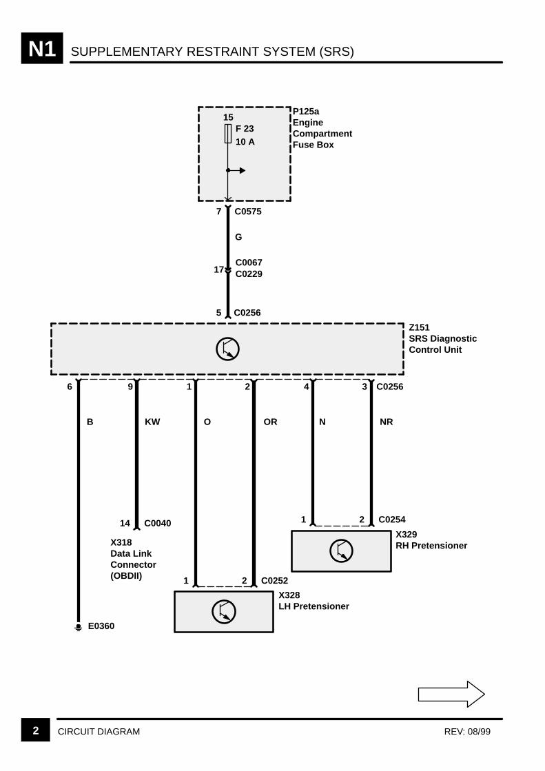
SUPPLEMENTARY RESTRAINT SYSTEM (SRS)N1
2 CIRCUIT DIAGRAM REV: 08/99
Z151SRS DiagnosticControl Unit
X328LH Pretensioner
15F 2310 A
7 C0575
C0067
1
C0229
G
E0360
14 C0040
2 C0252
X329RH Pretensioner
1 2 C0254
P125aEngineCompartmentFuse Box
17
C02565
6 9 1 2 4 3 C0256
B KW O OR N NR
X318Data LinkConnector(OBDII)
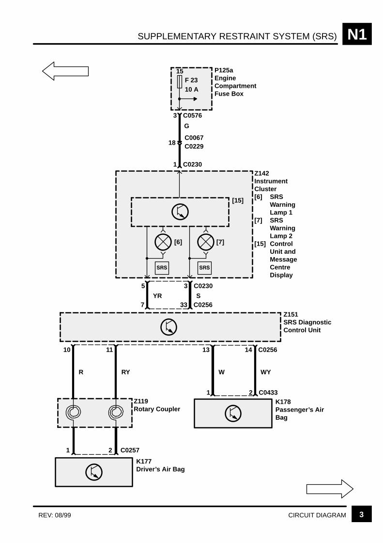
SUPPLEMENTARY RESTRAINT SYSTEM (SRS) N1
3CIRCUIT DIAGRAMREV: 08/99
[15]
Z142InstrumentCluster[6] SRS
WarningLamp 1
[7] SRSWarningLamp 2
[15] ControlUnit andMessageCentreDisplay
15F 2310 A
P125aEngineCompartmentFuse Box
3 C0576
G
18C0067C0229
1 C0230
[7][6]
33 C0256
3 C02305
7
Z151SRS DiagnosticControl Unit
14 C02561310 11
Z119Rotary Coupler
YR S
R RY
1 2 C0257
K177Driver’s Air Bag
K178Passenger’s AirBag
2 C04331
W WY
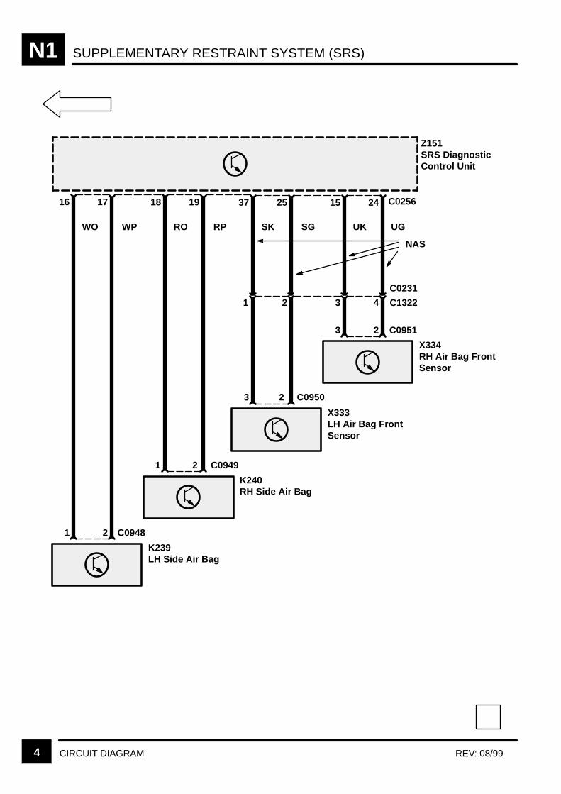
SUPPLEMENTARY RESTRAINT SYSTEM (SRS)N1
4 CIRCUIT DIAGRAM REV: 08/99
Z151SRS DiagnosticControl Unit
K239LH Side Air Bag
1 2 C0948
16 17
WO WP
K240RH Side Air Bag
1 2
18 19
RO RP
X333LH Air Bag FrontSensor
2 C0950
37 25
SK SG
X334RH Air Bag FrontSensor
3 2
15 24
UK UG
3
NAS
C0256
C0949
C1322
C0231
C0951
1 2 3 4

TRAILER AUXILIARY SOCKET P1
CIRCUIT OPERATION 1
CIRCUIT OPERATION
Accommodation within the system has been madefor the addition of a trailer lighting system to consistof 2 side lamps, 2 fog lamps, 2 reverse lamps, 2brake lamps, 1 LH indicator and 1 RH indicator.In addition to these loads, there is also a provisionfor a 10 amp battery feed to the trailer.
Bulb Failure Diagnosis With Trailer
The diagnosis of external bulb failures will bemodified by the presence of a trailer as follows:Brake lamps
Diagnosis of the RH vehicle and trailer lamps willonly detect a failure of all the filaments.
Diagnosis of the LH vehicle brake light is unaf-fected.
Rear side lamps
Diagnosis of the LH rear side lamps will onlydetect the failure of both the vehicle filament andthe trailer filament.
Diagnosis of the RH rear side lamps will onlydetect the failure of both the vehicle filament andthe trailer filament.
Reverse lamps
Diagnosis of the RH vehicle reverse light and theLH and RH trailer reverse lamps will only detectfailure of all of the filaments.
Diagnosis of the LH vehicle reverse light is unaf-fected.
Fog lamps
Diagnosis of the RH vehicle rear fog light and theLH and RH trailer fog lamps will only detect fai-lure of all of the filaments.
Diagnosis of the LH vehicle rear fog light is unaf-fected.

TRAILER AUXILIARY SOCKETP1
CIRCUIT OPERATION2
Direction indicators
The indicator warning lamp and trailer warning lampwill diagnose the status of the vehicle’s rearfilaments, and trailer direction indicator filamentsaccording to the following table:
ÁÁÁÁÁÁÁÁÁÁÁÁÁÁÁÁÁÁ
Indicator w/l ÁÁÁÁÁÁÁÁÁÁÁÁÁÁÁÁTrailer w/l ÁÁÁÁÁÁÁÁÁ
ÁÁÁÁÁÁÁÁÁVehicle filament ÁÁÁÁÁÁÁÁÁ
ÁÁÁÁÁÁÁÁÁTrailer filament
ÁÁÁÁÁÁÁÁÁÁÁÁÁÁÁÁÁÁ
Flash ÁÁÁÁÁÁÁÁÁÁÁÁÁÁÁÁFlash ÁÁÁÁÁÁÁÁÁ
ÁÁÁÁÁÁÁÁÁGood ÁÁÁÁÁÁÁÁÁ
ÁÁÁÁÁÁÁÁÁGood
ÁÁÁÁÁÁÁÁÁÁÁÁÁÁÁÁÁÁ
Flash ÁÁÁÁÁÁÁÁÁÁÁÁÁÁÁÁExtinguished ÁÁÁÁÁÁÁÁÁ
ÁÁÁÁÁÁÁÁÁGood ÁÁÁÁÁÁÁÁÁ
ÁÁÁÁÁÁÁÁÁFail/not fitted
ÁÁÁÁÁÁÁÁÁÁÁÁÁÁÁÁÁÁ
Flash ÁÁÁÁÁÁÁÁÁÁÁÁÁÁÁÁFlash ÁÁÁÁÁÁÁÁÁ
ÁÁÁÁÁÁÁÁÁFail ÁÁÁÁÁÁÁÁÁ
ÁÁÁÁÁÁÁÁÁGood
ÁÁÁÁÁÁÁÁÁÁÁÁÁÁÁÁÁÁ
Flash w/ double rate ÁÁÁÁÁÁÁÁÁÁÁÁÁÁÁÁExtinguished ÁÁÁÁÁÁÁÁÁ
ÁÁÁÁÁÁÁÁÁFail ÁÁÁÁÁÁÁÁÁ
ÁÁÁÁÁÁÁÁÁFail/not fitted
In the case of hazard light operation with trailerlamps fitted, the failure of a trailer direction indicatorlight will cause the trailer warning light to flash atdouble rate, while the direction indicator light willflash at the “standard” rate.
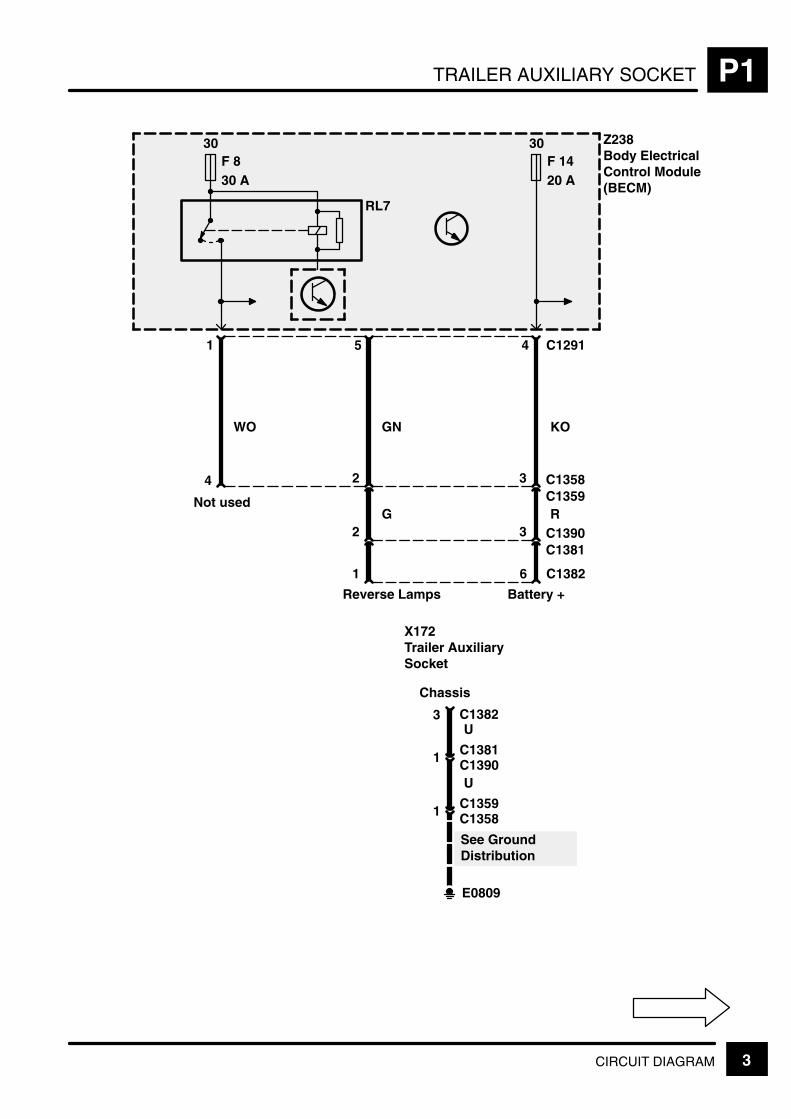
TRAILER AUXILIARY SOCKET P1
3CIRCUIT DIAGRAM
E0809
See GroundDistribution
1 C1358C1359
U
1 C1390C1381
U3 C1382
X172Trailer AuxiliarySocket
1 6 C1382
3C1359C135824
3C1381C13902
G R
GN
4 C129151
30F 830 A
RL7
30F 1420 A
Z238Body ElectricalControl Module(BECM)
KOWO
Battery +Reverse Lamps
Chassis
Not used

TRAILER AUXILIARY SOCKETP1
4 CIRCUIT DIAGRAM REV: 11/99
E0565
See GroundDistribution
1 C1375C1376
B
3 C1389C1415
W
3 C0499
X286Trailer MainSocket
4 2 C0499
5C1376C13753
2C1415C13894
G U
Rear Fog LampsRight DirectionIndicator Lamps
Chassis
1
4
1
Y
Left DirectionIndicator Lamps
3 C12831514
GY RYGR
Z238Body ElectricalControl Module(BECM)
RY
Rear Fog GuardLamps
S301
C1584 (MY 2000)(MY 1999)
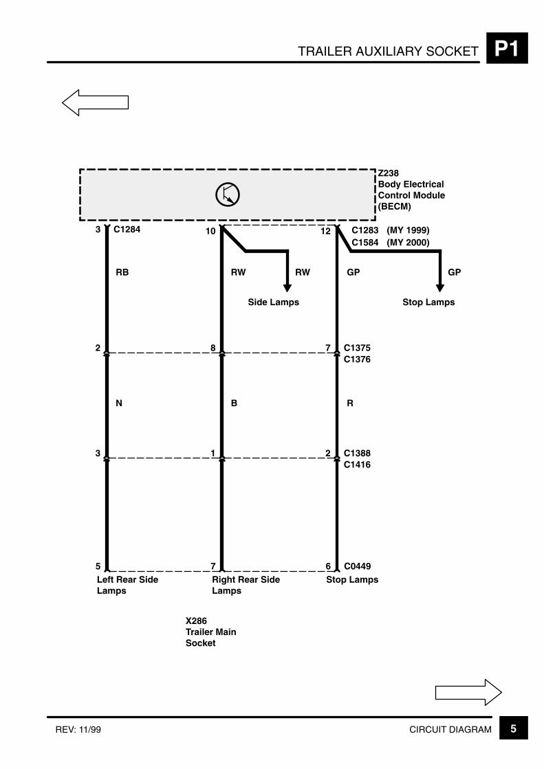
TRAILER AUXILIARY SOCKET P1
5CIRCUIT DIAGRAMREV: 11/99
X286Trailer MainSocket
7 6 C0449
7C1376C13758
2C1416C13881
B R
Stop LampsRight Rear SideLamps
5
2
3
N
Left Rear SideLamps
12 C1283103
RW GPRB
Z238Body ElectricalControl Module(BECM)
GP
Stop LampsSide Lamps
RW
C1284C1584 (MY 2000)
(MY 1999)

TRAILER AUXILIARY SOCKETP1
6 CIRCUIT DIAGRAM REV: 08/99
8
Z238Body ElectricalControl Module(BECM)
2 C0167
9 18 C1287
AutomaticTransmission
ManualTransmission
13 C0746
0 1
X157Reverse Switch
S551
E1355
UP UG
S608
S609
S610
UB
6 C0244
0 [1]
X
1
0 [2]
Y
2
0 [3]
Z
3 C0244
GN
B
BS
S607
E0808
C0989
1 C0167
See GroundDistribution
See GroundDistribution
X294Gear Box PositionSwitch
[1] X Switch[2] Y Switch[3] Z Switch
P 0 1 1R 0 0 1N 1 0 1D 1 0 03 0 0 02 0 1 01 1 1 0
Z* 1 1 1
X Y Z
AutomaticGearbox
1 =
0 =
* =
Switch Open
Switch Closed
Fault
3 5
C0745
C09884
2C0988C0745
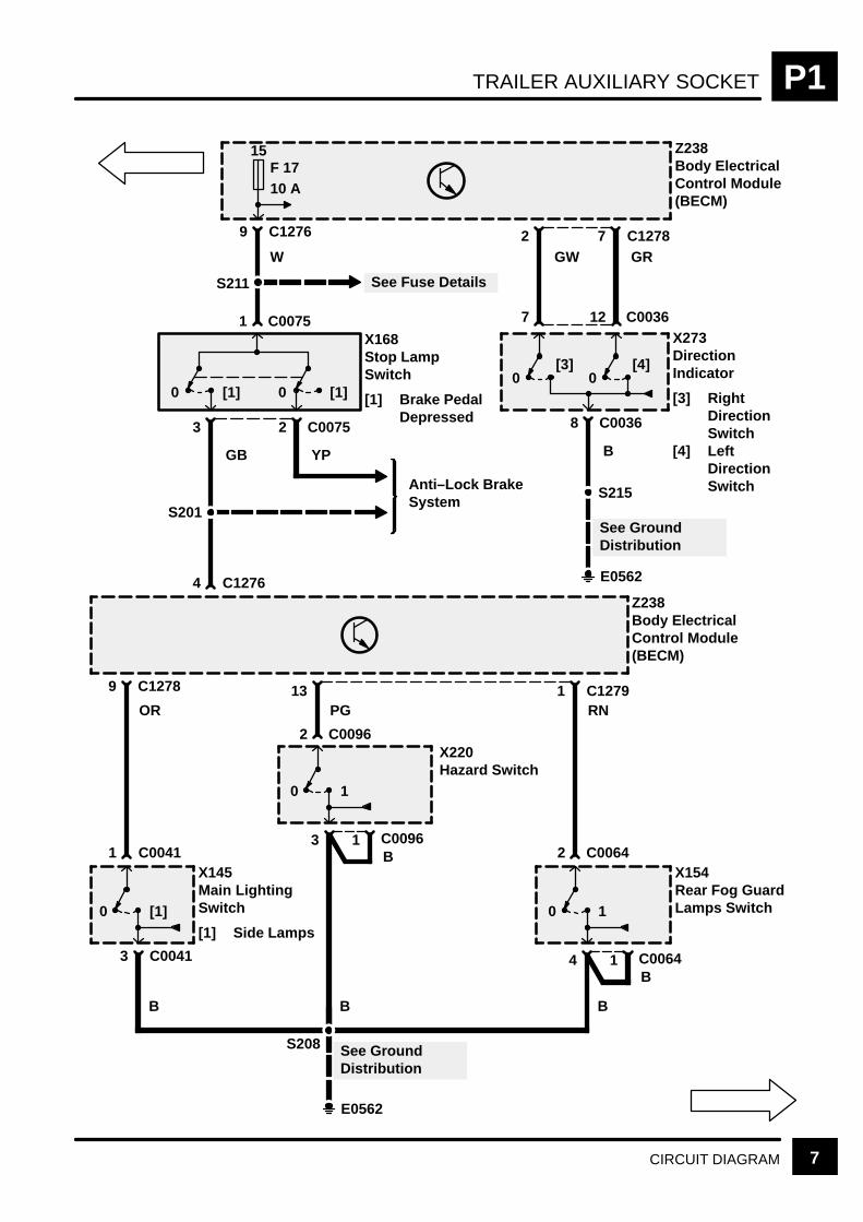
TRAILER AUXILIARY SOCKET P1
7CIRCUIT DIAGRAM
E0562
See GroundDistribution
S215
[1]0
X145Main LightingSwitch
[1] Side Lamps
3
1
C0041
B
OR
10
X154Rear Fog GuardLamps Switch
4 1 C0064
2 C0064
B
B
RN
10
X220Hazard Switch
3 1 C0096
2 C0096
B
B
PG
9 C1278 13 1 C1279
Z238Body ElectricalControl Module(BECM)
[3]0
X273DirectionIndicator
[3] RightDirectionSwitch
[4] LeftDirectionSwitch
8 C0036
7
[4]0
12 C0036
B
[1]0
X168Stop LampSwitch
[1] Brake PedalDepressed
3
[1]0
1 C0075
GB
W
9 C1276
Z238Body ElectricalControl Module(BECM)
E0562
See GroundDistribution
S208
GR7 C1278
GW2
2 C0075
YP
C0041
S211 See Fuse Details
Anti–Lock BrakeSystem
4 C1276
S201
15F 1710 A

TRAILER AUXILIARY SOCKETP1
8 CIRCUIT DIAGRAM
30F 110 A
Z238Body ElectricalControl Module(BECM)
7 C1276
See Fuse Details
S205
P
4 C023314
P
Z142InstrumentCluster
[15] Control UnitandMessageCentreDisplay
15 C02335133122188177
LG
3 C1280
LG
11
OG
9
OG
1
RG
10
RG
2
BG
5
BG
14
BB
E0564
Z238Body ElectricalControl Module(BECM)
[15]
AIR SUSPENSION S1
CIRCUIT OPERATION 1
CIRCUIT OPERATION
The Electronic Air Suspension (EAS) is designed tomaintain the selected vehicle height under varyingloads. This is achieved by adjusting the quantity ofair within the air springs located next to each wheel.It should be noted that the system is not intended tocontrol the roll or dive of the vehicle whilst corneringor braking. The accuracy of height control achievedis sufficient to ensure that no additional drivercontrolled means of adjusting the headlamp beam isrequired to compensate for different vehicle loadingconditions.
The system can operate in any one of five heights ormodes: Access, Low Profile, Standard Profile, HighProfile and Extended Profile. All heights with theexception of Extended Profile can be selected by thedriver using the ride height switches on the fascia.When Inhibit is selected (indicated by the Inhibitswitch tell–tale lamp being illuminated), automaticheight changes between Standard and Low Profileare disabled; it is recommended that StandardProfile Inhibit mode is selected whenever a trailer isbeing towed.
The ride height of the vehicle is displayed to thedriver by the LEDs in the ride height display adjacentto the ride height switches on the fascia. The LEDfor the current ride height is continuously illuminatedwhenever the engine is running. When a heightchange is taking place, the LED for the new targetheight flashes and the LED for the old heightremains continuously illuminated until the new targetheight is reached whereupon the old height LED isextinguished and the new height LED is continuouslyilluminated.
It should be noted that if any of the side doors or thetailgate are open when the vehicle speed is less than5 mph (8 km/h), all height changes are suspendeduntil the doors and tailgate are closed. If a door hasbeen open for more than 30 seconds, then thesystem will need “reminding” of the new height afterthe door has been closed. This condition is indicatedby the LEDs for the old and new heights both beingcontinously illuminated.
Application of the footbrake also causes any heightchanges to be suspended whilst it is pressed. If thefootbrake has been applied continously for morethan 3 minutes, then height changes are allowed toresume.
The ride height of the vehicle is correctly maintainedonly whilst the engine is running. To compensate forany changes in load after parking (e.g. driver orpassengers getting out),the EAS system will lower
the vehicle to the height of the lowest corner afterthe last door is closed. Furthermore, if the vehicleshould develop a lean due to temperature effects orair leakage whilst parked, the EAS system isautomatically re–powered every few hours to allowlimited corrections to the height to be achieved.
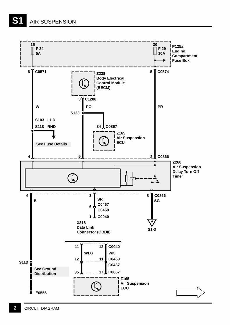
AIR SUSPENSIONS1
2 CIRCUIT DIAGRAM
P125aEngineCompartmentFuse Box
C05718
4
6
15F 245A
Z260Air SuspensionDelay Turn OffTimer
C05745
30F 2910A
PR
C08662
11 12
8
17
Z165Air SuspensionECU
35 C0867
11 C0469
C0040
WKWLG
S118
See Fuse Details
3 C1288
5
PO
S123
34
Z165Air SuspensionECU
C0867
12S113
See GroundDistribution
E0556
C08663SR
6 C0467
1
X318Data LinkConnector (OBDII)
B SG
A
S1-3
S103 LHD
RHD
W
Z238Body ElectricalControl Module(BECM)
C0469
C0467
C0040
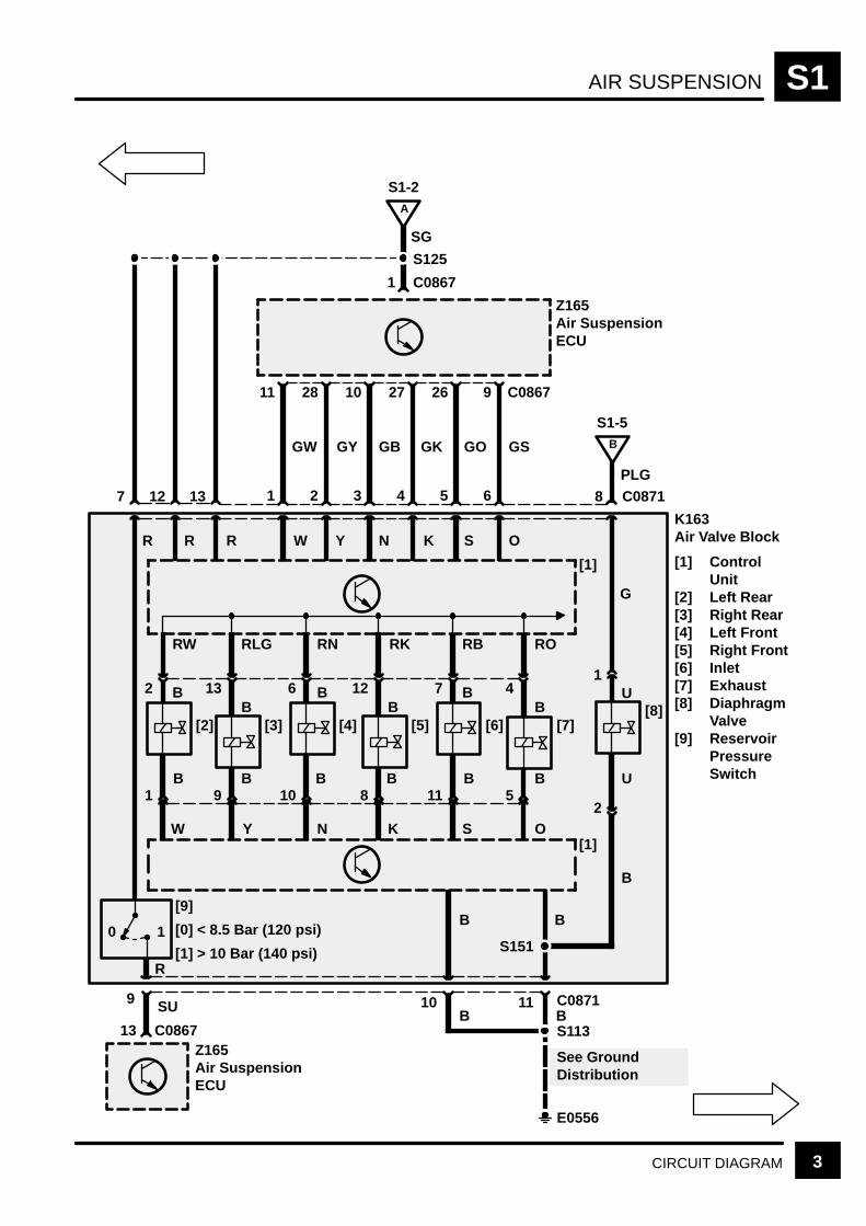
AIR SUSPENSION S1
3CIRCUIT DIAGRAM
B
K163Air Valve Block
[1] ControlUnit
[2] Left Rear[3] Right Rear[4] Left Front[5] Right Front[6] Inlet[7] Exhaust[8] Diaphragm
Valve[9] Reservoir
PressureSwitch
C0867
11 C0871
S113B
13 C08718
9 C0867
6
GS
10B
Z165Air SuspensionECU
1
A
S1-2
S125
PLG
B
S1-5
[1]
O
12
R
7
R
[1]
G
1
2
B
26
5
GO
27
4
GK
10
3
GB
28
2
GY
11
1
GW
R SKNYW
13Z165Air SuspensionECU
See GroundDistribution
E0556
9 SU
0 1
[9]B
S151
B
[7]
RO
4
5
B
B
O
[8]U
U
[6]
RB
7
11B
S
[5]
RK
12
8
B
B
K
[4]
RN
6
10
B
B
N
[3]
RLG
13
9
B
B
Y
[2]
RW
2
1
B
B
W
SG
C0867
R
[0] < 8.5 Bar (120 psi)
[1] > 10 Bar (140 psi)
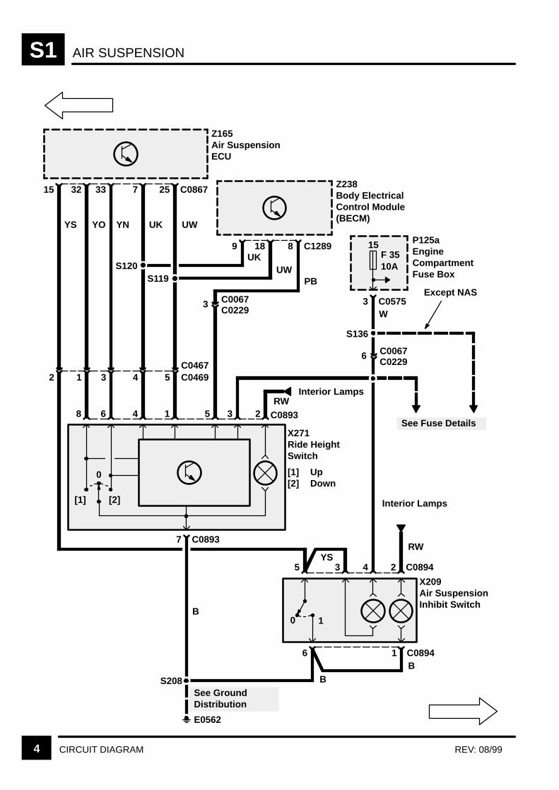
AIR SUSPENSIONS1
4 CIRCUIT DIAGRAM REV: 08/99
25 C0867
1
UW
Z165Air SuspensionECU
7
4
UK
33
6
YN
32
8
YO
15
YS
3 C0575W
P125aEngineCompartmentFuse Box
8
2
PB
18
3
UW
9
5
UK
2
RW
435YS
X209Air SuspensionInhibit Switch
2 1 3 4 5
X271Ride HeightSwitch
[1] Up[2] Down
7 C0893
0 1
C0893
C0894
16 C0894
S120
S208
B
See GroundDistribution
E0562
BB
S119
[1] [2]
Interior Lamps
S136
C0467C0469
Interior Lamps
See Fuse Details
RW
0
C1289
3 C0067C0229
15F 3510A
Z238Body ElectricalControl Module(BECM)
6 C0067C0229
Except NAS
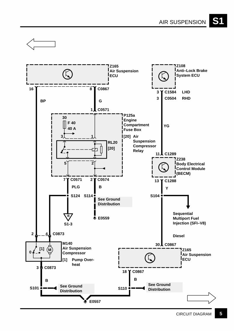
AIR SUSPENSION S1
5CIRCUIT DIAGRAM
30F 4040 A
RL20
[20]
25
13
7 C0571
B
Z108Anti–Lock BrakeSystem ECU
3 C1584
Z165Air SuspensionECU
16
2 C0574
PLG
1 C0571
8 C0867
GBP
P125aEngineCompartmentFuse Box
[20] AirSuspensionCompressorRelay
Z238Body ElectricalControl Module(BECM)
13 C1288
11 C1289
YG
C0504
LHD
RHD
S114 S104
Y
E0559
See GroundDistribution
B
S1-3
S124
SequentialMultiport FuelInjection (SFI–V8)
Z165Air SuspensionECU
18 C0867
30 C0867M
E0557
M140Air SuspensionCompressor
[1] Pump Over-heat
0[1]
3 C0873
4 C08732
B B
S110See GroundDistributionS101 See Ground
Distribution
Diesel
3
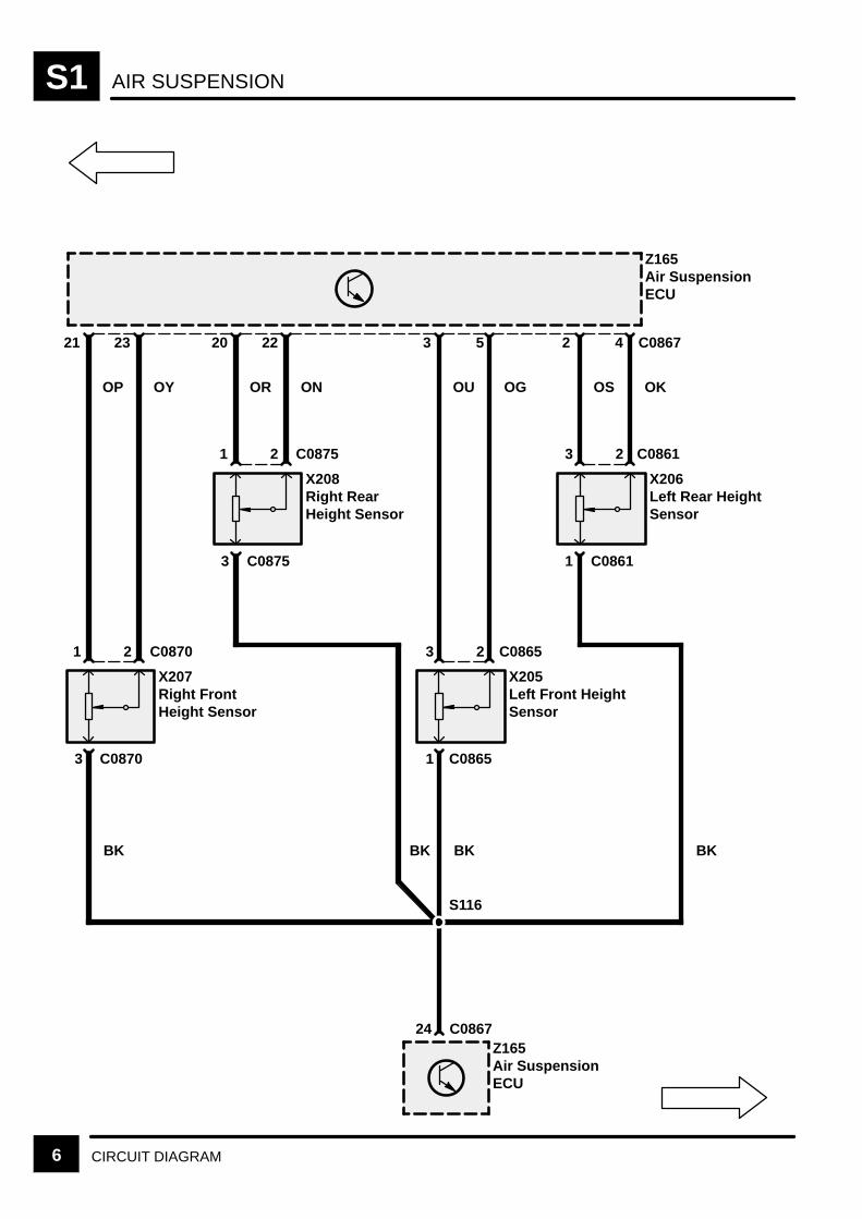
AIR SUSPENSIONS1
6 CIRCUIT DIAGRAM
Z165Air SuspensionECU
21 5 C0867
X207Right FrontHeight Sensor
23
OP OY
3 C0870
1 2 C0870
BK
20
X208Right RearHeight Sensor
22
OR ON
3 C0875
1 2 C0875
BK
3
X205Left Front HeightSensor
OU OG
1 C0865
3 2 C0865
BK
2
X206Left Rear HeightSensor
4
OS OK
1 C0861
3 2 C0861
BK
Z165Air SuspensionECU
24 C0867
S116

AIR SUSPENSION S1
7CIRCUIT DIAGRAM
Z238Body ElectricalControl Module(BECM)
C128920
Z165Air SuspensionECU
31 C0867
GP
S106
S131
Anti–Lock BrakeSystem
S106
LHDRHD
Z132Engine ControlModule (ECM)
17 C0637
S
Z132Engine ControlModule (ECM)
50 C0411
Diesel Petrol
20C0203C0448 20
C0162C0448
Z165Air SuspensionECU
12 C0867
C12889
14C0067C0229
C12769
W
[1]0[1]0
1 C0075
3 C00752
X168Stop Lamp Switch
[1] Brake Pedal De-pressed
S201
Anti–Lock BrakeSystem
S
15F 1710 A
S
YPGP

AIR SUSPENSIONS1
8 CIRCUIT DIAGRAM REV: 08/99
9 18
UP UG
S608
S609
S610
UB
AutomaticGearbox
6 C0244
0 [1]
X
1
0 [2]
Y
2
0 [3]
Z
3 C0244
BS
S607
E0808
See GroundDistribution
X294Gear Box PositionSwitch
[1] X Switch[2] Y Switch[3] Z Switch
P 0 1 1
R 0 0 1N 1 0 1D 1 0 03 0 0 02 0 1 01 1 1 0Z* 1 1 1
X Y Z
C086714
BK
Z238Body ElectricalControl Module(BECM)
Z165Air SuspensionECU
1 C0105
0 [1]
X191HandbrakeSwitch
[1] HandbrakeOn
S607
E0808
BK
B
1 C0091
See GroundDistribution
AutomaticTransmission
1 =
0 =
* =
Switch Open
Switch Closed
Fault
2 C128817 C12878
3 5
C0745
C09884
2C0988C0745
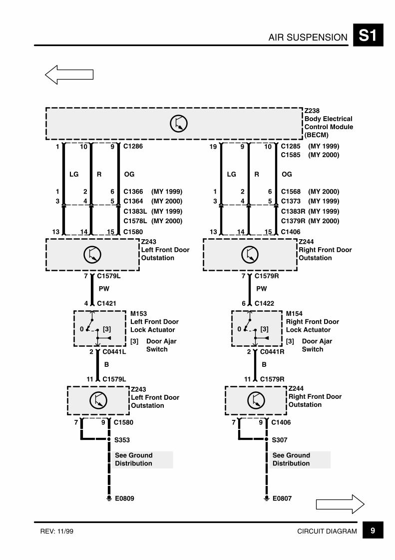
AIR SUSPENSION S1
9CIRCUIT DIAGRAMREV: 11/99
1
LG
3
13 C1580
Z238Body ElectricalControl Module(BECM)
C128610
R
4
14
9
OG
5 C1364
C1383L
15Z243Left Front DoorOutstation
C1579L7
PW
C14214
M153Left Front DoorLock Actuator
[3] Door AjarSwitch
0 [3]
C0441L2
B
C1579L11
Z243Left Front DoorOutstation
C158097
S353
E0809
See GroundDistribution
19
LG
3
13 C1406
C12859
R
4
14
10
OG
5 C1373
C1383R
15Z244Right Front DoorOutstation
C1579R7
PW
C14226
M154Right Front DoorLock Actuator
[3] Door AjarSwitch
0 [3]
C0441R2
B
C1579R11Z244Right Front DoorOutstation
C140697
S307
E0807
See GroundDistribution
1 2 6 C1366 C1568(MY 1999)(MY 2000)1 2 6
(MY 2000)(MY 1999)
C1379R(MY 2000)(MY 1999)
C1578L
(MY 2000)(MY 1999)
C1585 (MY 2000)(MY 1999)
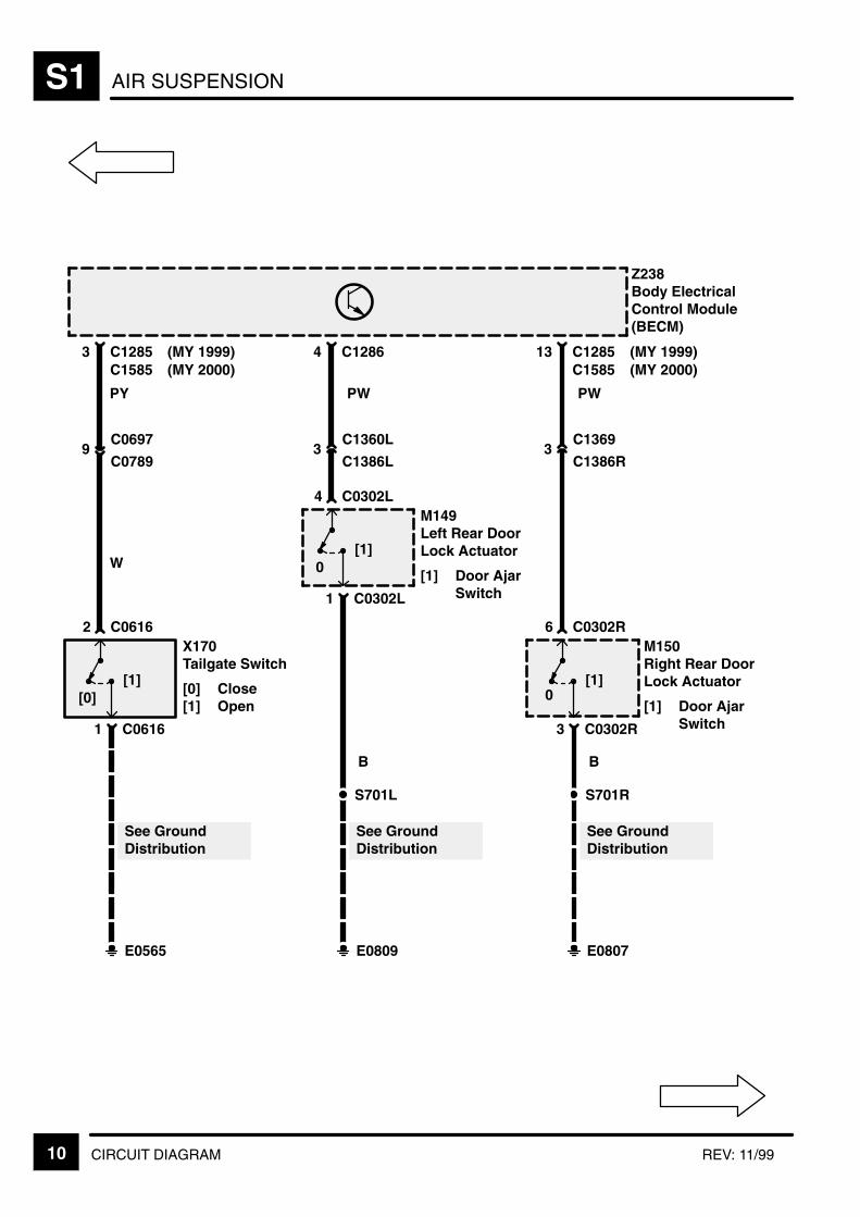
AIR SUSPENSIONS1
10 CIRCUIT DIAGRAM REV: 11/99
C12853
9C0697
C0789
C06162X170Tailgate Switch
[0] Close[1] Open
[1]
C06161
E0565
See GroundDistribution
PY
W
C12864
3C1360L
C1386L
C0302L4M149Left Rear DoorLock Actuator
[1] Door AjarSwitch
0[1]
C0302L1
E0809
See GroundDistribution
PW
S701L
B
C128513
3C1369
C1386R
C0302R6M150Right Rear DoorLock Actuator
[1] Door AjarSwitch
0[1]
C0302R3
E0807
See GroundDistribution
PW
S701R
B
Z238Body ElectricalControl Module(BECM)
C1585 (MY 2000)(MY 1999)
C1585 (MY 2000)(MY 1999)
[0]

AIR SUSPENSION S1
11CIRCUIT DIAGRAM
30F 110 A
Z238Body ElectricalControl Module(BECM)
7 C1276
See Fuse Details
S205
P
4 C023314
P
Z142InstrumentCluster
[15] Control UnitandMessageCentreDisplay
15 C02335133122188177
LG
3 C1280
LG
11
OG
9
OG
1
RG
10
RG
2
BG
5
BG
14
BB
E0564
Z238Body ElectricalControl Module(BECM)
[15]

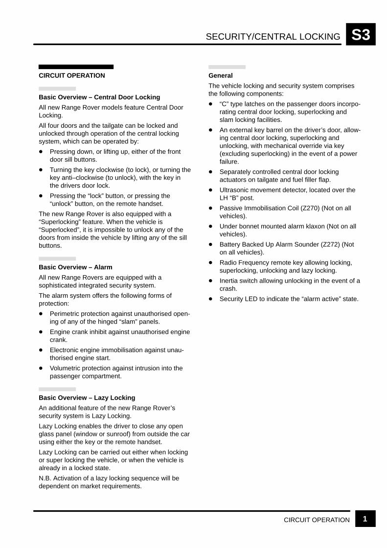
SECURITY/CENTRAL LOCKING S3
CIRCUIT OPERATION 1
CIRCUIT OPERATION
Basic Overview – Central Door Locking
All new Range Rover models feature Central DoorLocking.
All four doors and the tailgate can be locked andunlocked through operation of the central lockingsystem, which can be operated by:
Pressing down, or lifting up, either of the frontdoor sill buttons.
Turning the key clockwise (to lock), or turning thekey anti–clockwise (to unlock), with the key inthe drivers door lock.
Pressing the “lock” button, or pressing the“unlock” button, on the remote handset.
The new Range Rover is also equipped with a“Superlocking” feature. When the vehicle is“Superlocked”, it is impossible to unlock any of thedoors from inside the vehicle by lifting any of the sillbuttons.
Basic Overview – Alarm
All new Range Rovers are equipped with asophisticated integrated security system.
The alarm system offers the following forms ofprotection:
Perimetric protection against unauthorised open-ing of any of the hinged “slam” panels.
Engine crank inhibit against unauthorised enginecrank.
Electronic engine immobilisation against unau-thorised engine start.
Volumetric protection against intrusion into thepassenger compartment.
Basic Overview – Lazy Locking
An additional feature of the new Range Rover’ssecurity system is Lazy Locking.
Lazy Locking enables the driver to close any openglass panel (window or sunroof) from outside the carusing either the key or the remote handset.
Lazy Locking can be carried out either when lockingor super locking the vehicle, or when the vehicle isalready in a locked state.
N.B. Activation of a lazy locking sequence will bedependent on market requirements.
General
The vehicle locking and security system comprisesthe following components:
“C” type latches on the passenger doors incorpo-rating central door locking, superlocking andslam locking facilities.
An external key barrel on the driver’s door, allow-ing central door locking, superlocking andunlocking, with mechanical override via key(excluding superlocking) in the event of a powerfailure.
Separately controlled central door lockingactuators on tailgate and fuel filler flap.
Ultrasonic movement detector, located over theLH “B” post.
Passive Immobilisation Coil (Z270) (Not on allvehicles).
Under bonnet mounted alarm klaxon (Not on allvehicles).
Battery Backed Up Alarm Sounder (Z272) (Noton all vehicles).
Radio Frequency remote key allowing locking,superlocking, unlocking and lazy locking.
Inertia switch allowing unlocking in the event of acrash.
Security LED to indicate the “alarm active” state.

SECURITY/CENTRAL LOCKINGS3
CIRCUIT OPERATION2
Remote Handset Operation
The handset has two buttons, lock/superlock andunlock. The operation is as follows:
Lock – single press of lock button.
Superlock – double press of lock button (within 1 second).
Unlock – single press of unlock button fromeither locked or superlocked.
Lazy lock – press and hold lock button for morethan 1 second.
(NB Hold on second press if superlock requiredas well.)
Lazy Seats – press unlock button for more than1 second.
(NB This will unlock as well.)
Locking operation
There are six different ways to lock a new RangeRover. These are:
Sill Locking
Depressing either of the front door sill buttons whileboth front doors are closed will result in all the doorsand the tailgate locking, and the vehicle entering asill locked state.
In this state the alarm remains inactive (provides noprotection), with no LED flash.
Sill locking can be achieved independently of key–inand ignition switch status.
Slam Locking:
Depressing either of the front door sill buttons witheither front door open, will result in all the doors andthe tailgate locking and the vehicle entering a slamlocked state.
Following a slam locking operation, the alarm willenter the perimetric mode, engine crank will bedisabled and electronic engine immobilisation will beactivated.
Attempting to slam lock the vehicle with either thekey in the ignition, or the ignition on, will causeunlocking of all the doors.
Key Locking
A single turn of the key towards the front of thevehicle will result in all the doors and tailgate locking.
The alarm will enter the perimetric mode, enginecrank will be disabled and electronic engineimmobilisation will be activated.
Key Superlocking
A double turn of the key in a clockwise direction (i.e.towards the front of the vehicle) within 2 seconds,provided the doors, tailgate and bonnet are closed,will result in all the doors being superlocked.
The alarm will enter the perimetric mode, enginecrank will be disabled and electronic engineimmobilisation will be activated.
Remote Locking
A single press of the lock button on the remotehandset will result in all the doors and the tailgatelocking.
The alarm will enter the perimetric mode, enginecrank will be disabled and electronic engineimmobilisation will be activated.
Remote Superlocking
A double press of the lock button on the remotehandset within 2 seconds, provided the doors,tailgate and bonnet are closed, will result in all thedoors being superlocked (subject to ultrasonic lookaround – see Ultrasonic Sensor).
Providing all the windows are closed, the perimetricand volumetric alarm will be set. If all the windowsare not closed, then only the perimetric alarm will beset.
Engine crank will be disabled and electronic engineimmobilisation will be activated.
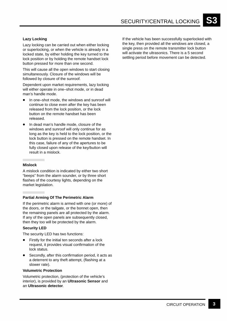
SECURITY/CENTRAL LOCKING S3
CIRCUIT OPERATION 3
Lazy Locking
Lazy locking can be carried out when either lockingor superlocking, or when the vehicle is already in alocked state, by either holding the key turned to thelock position or by holding the remote handset lockbutton pressed for more than one second.
This will cause all the open windows to start closingsimultaneously. Closure of the windows will befollowed by closure of the sunroof.
Dependent upon market requirements, lazy lockingwill either operate in one–shot mode, or in deadman’s handle mode.
In one–shot mode, the windows and sunroof willcontinue to close even after the key has beenreleased from the lock position, or the lockbutton on the remote handset has beenreleased.
In dead man’s handle mode, closure of thewindows and sunroof will only continue for aslong as the key is held to the lock position, or thelock button is pressed on the remote handset. Inthis case, failure of any of the apertures to befully closed upon release of the key/button willresult in a mislock.
Mislock
A mislock condition is indicated by either two short“beeps” from the alarm sounder, or by three shortflashes of the courtesy lights, depending on themarket legislation.
Partial Arming Of The Perimetric Alarm
If the perimetric alarm is armed with one (or more) ofthe doors, or the tailgate, or the bonnet open, thenthe remaining panels are all protected by the alarm.If any of the open panels are subsequently closed,then they too will be protected by the alarm.
Security LED
The security LED has two functions:
Firstly for the initial ten seconds after a lockrequest, it provides visual confirmation of thelock status.
Secondly, after this confirmation period, it acts asa deterrent to any theft attempt, (flashing at aslower rate).
Volumetric Protection
Volumetric protection, (protection of the vehicle’sinterior), is provided by an Ultrasonic Sensor andan Ultrasonic detector .
If the vehicle has been successfully superlocked withthe key, then provided all the windows are closed, asingle press on the remote transmitter lock buttonwill activate the ultrasonics. There is a 5 secondsettling period before movement can be detected.
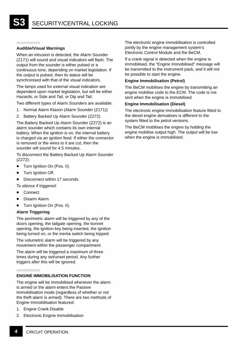
SECURITY/CENTRAL LOCKINGS3
CIRCUIT OPERATION4
Audible/Visual Warnings
When an intrusion is detected, the Alarm Sounder(Z171) will sound and visual indicators will flash. Theoutput from the sounder is either pulsed or acontinuous tone, depending on market legislation. Ifthe output is pulsed, then its status will besynchronised with that of the visual indicators.
The lamps used for external visual indication aredependent upon market legislation, but will be eitherHazards, or Side and Tail, or Dip and Tail.
Two different types of Alarm Sounders are available:
1. Normal Alarm Klaxon (Alarm Sounder (Z171))
2. Battery Backed Up Alarm Sounder (Z272)
The Battery Backed Up Alarm Sounder (Z272) is analarm sounder which contains its own internalbattery. When the ignition is on, the internal batteryis charged via an ignition feed. If either the connectoris removed or the wires to it are cut, then thesounder will sound for 4.5 minutes.
To disconnect the Battery Backed Up Alarm Sounder(Z272):
Turn Ignition On (Pos. II).
Turn Ignition Off.
Disconnect within 17 seconds.
To silence if triggered:
Connect.
Disarm Alarm.
Turn Ignition On (Pos. II).
Alarm Triggering
The perimetric alarm will be triggered by any of thedoors opening, the tailgate opening, the bonnetopening, the ignition key being inserted, the ignitionbeing turned on, or the inertia switch being tripped.
The volumetric alarm will be triggered by anymovement within the passenger compartment.
The alarm will be triggered a maximum of threetimes during any set/unset period. Any furthertriggers after this will be ignored.
ENGINE IMMOBILISATION FUNCTION
The engine will be immobilised whenever the alarmis armed or the alarm enters the PassiveImmobilisation mode (regardless of whether or notthe theft alarm is armed). There are two methods ofEngine Immobilisation featured:
1. Engine Crank Disable
2. Electronic Engine Immobilisation
The electronic engine immobilisation is controlledjointly by the engine management system’sElectronic Control Module and the BeCM.
If a crank signal is detected when the engine isimmobilised, the “Engine Immobilised” message willbe transmitted to the instrument pack, and it will notbe possible to start the engine.
Engine Immobilisation (Petrol)
The BeCM mobilises the engine by transmitting anengine mobilise code to the ECM. The code is notsent when the engine is immobilised.
Engine Immobilisation (Diesel)
The electronic engine immobilisation feature fitted tothe diesel engine derivatives is different to thesystem fitted to the petrol versions.
The BeCM mobilises the engine by holding theengine mobilise output high. The output will be lowwhen the engine is immobilised.

SECURITY/CENTRAL LOCKING S3
CIRCUIT OPERATION 5
Passive Immobilisation
The following conditions will passively immobilise thevehicle:
30 seconds after ignition has been turned off andthe driver’s door has been opened.
30 seconds after ignition has been turned off, thekey removed, and the driver’s door has beenopened.
10 minutes after ignition has been turned off andthe key removed (without opening the driver’sdoor).
The handset becomes desynchronised (or withan improperly functioning handset).
The vehicle can be mobilised by any of the followingmethods:
Turn the ignition on (The handset must be func-tioning properly and within close proximity to thekey!)
Press unlock button on the handset
Enter EKA code
NOTE: The vehicle will remain immobilised byattempting to turn the ignition on with the handsetdetached from the key ring (or with an improperlyfunctioning handset).
If the handset becomes desynchronised (or isfunctioning improperly), the engine will be passivelyimmobilised. If an attempt is made to start theengine, the message “Engine Disabled, PressRemote” will be displayed on the message centre. Tomobilise the engine the EKA code must be enteredand the handset (when functioning properly)resynchronised.
Passive Immobilisation Coil (Z270)
A magnetic field is generated by the passiveImmobilisation Coil (Z270) contained in the steeringcolumn. This field excites a receiving coil in thehandset causing it to transmit a mobilisation signal tothe BeCM. If the BeCM does not receive this signalfrom the handset, the vehicle will remainimmobilised.
Handset Transmitter Resynchronisation
The Theft Alarm Unit (Z163) will remainsynchronised with the handset unless:
The handset’s batteries have been removed.
The vehicle’s battery has been disconnected.
NOTE: All handsets must be resynchronised whenthe vehicle’s battery has been disconnected.
A handset may be resynchronised by performing akey lock, or unlock, on either front door within 30seconds of performing a remote lock, superlock, orunlock function. The BeCM uses the change of stateof the CDL Switch to initiate resynchronisation.
Emergency Key Access (EKA)
EKA is used to disarm the theft alarm and mobilisethe vehicle in the event of a handset failure. This ispossible through a series of locks and unlocks withthe key in the driver’s door lock cylinder. With thevehicle locked and the alarm armed, turn the key therequired number of times according to the followingsequence:
1. To enter the first digit, turn the key the requirednumber of times to the unlock position.
2. To enter the second digit, turn the key therequired number of times to the lock position.
3. To enter the third digit, turn the key the requirednumber of times to the unlock position.
4. To enter the fourth digit, turn the key the requirednumber of times to the lock position.
5. Turn the key to the unlock position to unlock thedoors, disarm the alarm, and mobilise thevehicle.
NOTE: The key must be fully turned to the rest andlock/unlock position each time.
After 5 wrong attempts, you must wait 10 minutes.

SECURITY/CENTRAL LOCKINGS3
6 CIRCUIT DIAGRAM REV: 11/99
30F 1520 A
17 C1283
P
S302
Z238Body ElectricalControl Module(BECM)
See Fuse Details
6 C1285
OR
X229Key–In Switch
[1] KeyInserted
3
4
3 C1279
NW
12
R
[1]0
Z270PassiveImmobilisationCoil
1 C0672
2 C0672
S215
See GroundDistribution
E0562
BB
Z250Alarm R.F.Aerial Module
1 C03583
2 C0358
E0565
S301
See GroundDistribution
B
Antenna
C1584 (MY 2000)(MY 1999)
C1585 (MY 2000)(MY 1999)
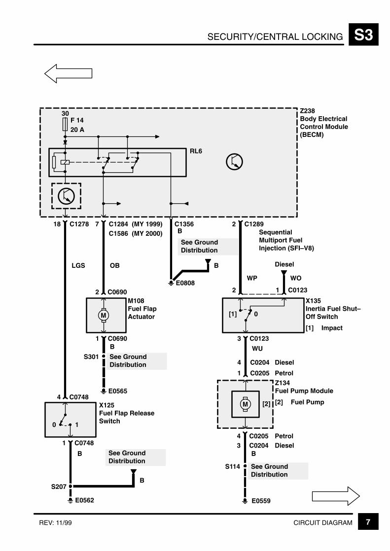
SECURITY/CENTRAL LOCKING S3
7CIRCUIT DIAGRAMREV: 11/99
X125Fuel Flap ReleaseSwitch10
S207
B
1 C0748
See GroundDistribution
E0565
E0562
See GroundDistribution
B
4 C0748
S301
B1 C0690
2 C0690
M
M108Fuel FlapActuator
LGS OB
B
E0808
See GroundDistribution
B
WP WO
SequentialMultiport FuelInjection (SFI–V8)
X135Inertia Fuel Shut–Off Switch
[1] Impact
0[1]
3 C0123
2
WU
1 C0123
Z134Fuel Pump Module
[2] Fuel Pump
4 C0205
1 C0205
M [2]
See GroundDistribution
E0559
S114
B
30F 1420 A
2 C12897 C128418 C1278
Z238Body ElectricalControl Module(BECM)
RL6
Diesel
4 C0204 Diesel
Petrol
Petrol3 C0204 Diesel
C1356C1586 (MY 2000)
(MY 1999)
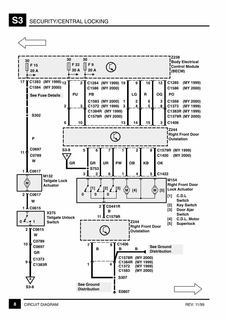
SECURITY/CENTRAL LOCKINGS3
8 CIRCUIT DIAGRAM REV: 11/99
F 9
X275Tailgate UnlockSwitch10
2 C0615
See Fuse Details
1 C0615
S302
2 C0617
1 C0617
M
M132Tailgate LockActuator
OK
P
8 C1579R
17 C1283
1
11C0697
C0789
W
A
S3-8
10C0789C0697
9C1373C1383R
W
GR
Z244Right Front DoorOutstation
5 C1422
KB
2
4
OB
1
1
PW
7
6
UR
6
2
GR
5
3
A
S3-8
S753GR
30F 1520 A
2 C0441R
[1]
0
[2]
0
[3]
0M M
Z244Right Front DoorOutstation
11 C1579R
7 9 C1406
B
E0807
4 C1384RC1578R
B B B See GroundDistribution
S307
W
[4] [5]
M154Right Front DoorLock Actuator
[1] C.D.LSwitch
[2] Key Switch[3] Door Ajar
Switch[4] C.D.L. Motor[5] Superlock
See GroundDistribution
Z238Body ElectricalControl Module(BECM)
30F 2230 A
30
20 A
C1584 (MY 2000)(MY 1999)
(MY 1999)
PO
12 C1285
3 C1406
8C1383RC1373
OG
10
15
5
R
9
14
4
LG
19
13
3
PB
2 C1284
10
3C1384RC1372
PU
12
6
2
C1586 (MY 2000)(MY 1999)
C1583 (MY 2000)
(MY 1999)C1578R (MY 2000)
C1586 (MY 2000)(MY 1999)
3 C1568621(MY 1999)(MY 2000)
(MY 2000)(MY 1999)
C1379R
C1583C1372
(MY 1999)(MY 2000)
(MY 2000)(MY 1999)
C1400 (MY 2000)(MY 1999)
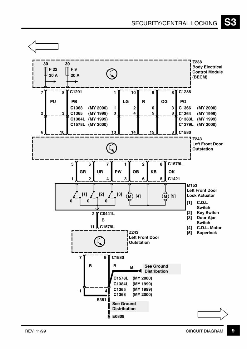
SECURITY/CENTRAL LOCKING S3
9CIRCUIT DIAGRAMREV: 11/99
OK
8 C1579L
1
Z243Left Front DoorOutstation
5 C1421
2 C0441L
[1]
0
[2]
0
[3]
0M M
Z243Left Front DoorOutstation
11 C1579L
7 9 C1580
B
B
[4] [5]
KB
2
6
OB
1
3
PW
7
4
UR
6
2
GR
5
1
M153Left Front DoorLock Actuator
[1] C.D.LSwitch
[2] Key Switch[3] Door Ajar
Switch[4] C.D.L. Motor[5] Superlock
Z238Body ElectricalControl Module(BECM)
30F 2230 A
30F 920 A
B
E0809
See GroundDistribution
S351
4 C1365C1384L
B See GroundDistribution
C1578L
C1368 (MY 2000)(MY 1999)(MY 1999)(MY 2000)
(MY 1999)
PO
8 C1286
3 C1580
8C1383LC1364
OG
9
15
5
R
10
14
4
LG
1
13
3
PB
8 C1291
10
3C1384LC1365
C1578L (MY 2000)(MY 1999)
C1368 (MY 2000) 3 C1366621(MY 1999)
(MY 2000)(MY 1999)
(MY 2000)
C1379L
PU
7
6
2
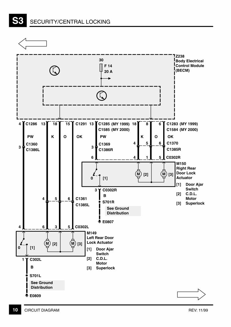
SECURITY/CENTRAL LOCKINGS3
10 CIRCUIT DIAGRAM REV: 11/99
E0809
See GroundDistribution
S701L
B
3C1386L
1 C302L
OK
5 C0302L
[1]0M M[2] [3]
36
OKPW
4
C1360
6
C1385L
C136154
15 C12914 C1286 13 18
M149Left Rear DoorLock Actuator
[1] Door AjarSwitch
[2] C.D.L.Motor
[3] Superlock
E0807
See GroundDistribution
S701R
B
3C1386R
3 C0302R
OK
5 C0302R
[1]0M M[2] [3]
14
OKPW
6
C1369 6
C1385R
C137054
6 C128313 C1285 18 8
M150Right RearDoor LockActuator
[1] Door AjarSwitch
[2] C.D.L.Motor
[3] Superlock
Z238Body ElectricalControl Module(BECM)
30
F 1420 A
C1585 (MY 2000)(MY 1999)
C1584 (MY 2000)(MY 1999)
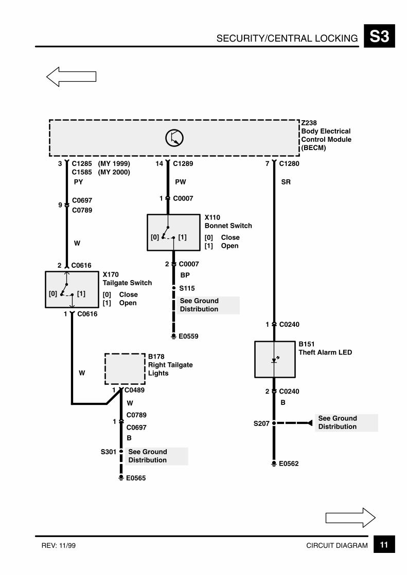
SECURITY/CENTRAL LOCKING S3
11CIRCUIT DIAGRAMREV: 11/99
Z238Body ElectricalControl Module(BECM)
14 C1289
PW
1 C0007
2 C0007
S115
See GroundDistribution
E0559
X110Bonnet Switch
[0] Close[1] Open
BP
7 C1280
SR
1 C0240
2 C0240
S207See GroundDistribution
E0562
B151Theft Alarm LED
B
3 C1285
PY
9C0789C0697
X170Tailgate Switch
[0] Close[1] Open
2 C0616
1 C0616
W
B178Right TailgateLights
1 C0489
E0565
See GroundDistribution
S301
1C0697
C0789
W
B
W
C1585 (MY 2000)(MY 1999)
[1][0]
[1][0]
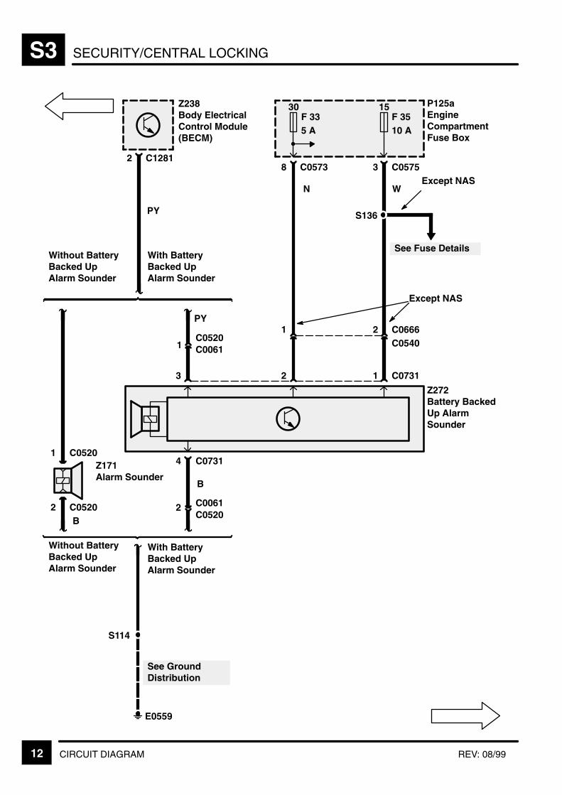
SECURITY/CENTRAL LOCKINGS3
12 CIRCUIT DIAGRAM REV: 08/99
See GroundDistribution
S114
P125aEngineCompartmentFuse Box
15F 3510 A
30F 335 A
8 C0573
N W
2 C1281
Z238Body ElectricalControl Module(BECM)
Without BatteryBacked UpAlarm Sounder
With BatteryBacked UpAlarm Sounder
PY
PY
1C0520
2C0540
1
3 C0575
1 C07312
Z272Battery BackedUp AlarmSounder
3
1 C0520
2 C0520
Z171Alarm Sounder
C00612B
Without BatteryBacked UpAlarm Sounder
With BatteryBacked UpAlarm Sounder
C07314
B
Except NAS
E0559
C0061
C0520
S136
See Fuse Details
Except NAS
C0666
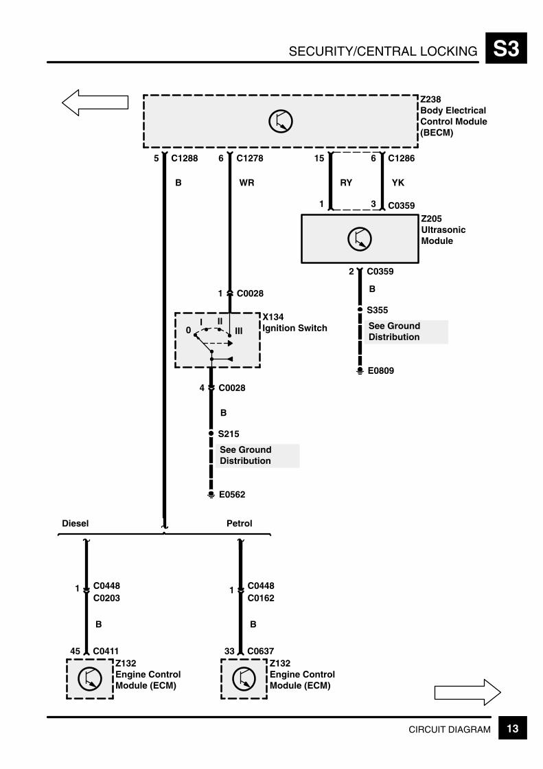
SECURITY/CENTRAL LOCKING S3
13CIRCUIT DIAGRAM
6 C1286
Z238Body ElectricalControl Module(BECM)
3 C0359
2 C0359
YK
15
1
RY
E0809
S355
B
See GroundDistribution
C12885
Z132Engine ControlModule (ECM)
33 C0637
B
Z132Engine ControlModule (ECM)
45 C0411
Diesel Petrol
1C0203C0448 1
C0162C0448
Z205UltrasonicModule
E0562
S215
B
See GroundDistribution
0I II
III
X134Ignition Switch
C12786
WRB
4 C0028
1 C0028
B

SECURITY/CENTRAL LOCKINGS3
14 CIRCUIT DIAGRAM REV: 11/99
(MY 1999)
PO
8 C1286
Z238Body ElectricalControl Module(BECM)
3 C1580
Z243Left Front DoorOutstation
30F 2230 A
30F 920 A
12 C1364
C1383L
8C1383LC1364
Z243Left Front DoorOutstation
OG
9
15
5
R
10
14
4
LG
1
13
3
PB
8 C1291
10
3C1384LC1365
16 C158084SWSGYR
1 C156535
M130Left FrontWindow MotorM
42
YUY1 C1580
11
10
6 C1565BO
Z238Body ElectricalControl Module(BECM)
3 C1286
7
B
9 C1580
B
E0809
See GroundDistribution
S351
4C1365C1384L1
B See GroundDistribution
C1578L (MY 2000)(MY 1999)
C1368 (MY 2000) 3 C1366621(MY 1999)
(MY 2000)(MY 1999)
(MY 2000)
C1379L
(MY 1999)C1379L (MY 2000)
5 C13664 (MY 2000)(MY 1999)
4 C1578L1
C1368 (MY 2000)(MY 1999)(MY 1999)(MY 2000)
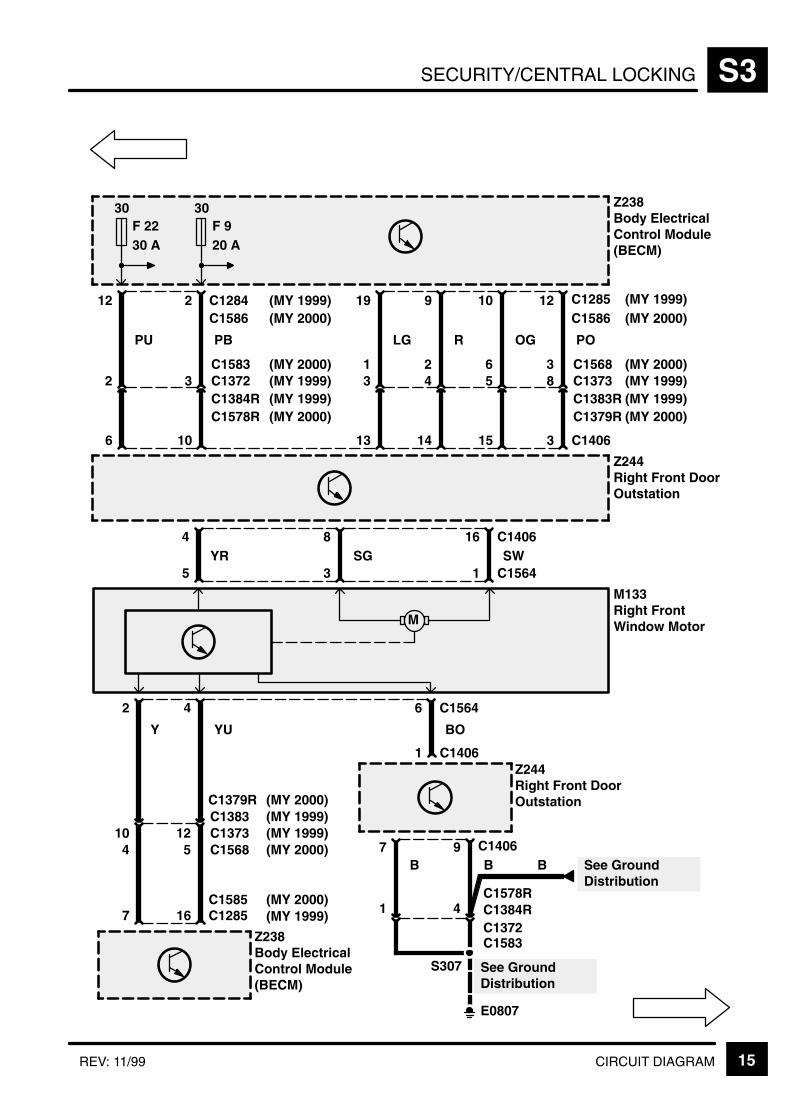
SECURITY/CENTRAL LOCKING S3
15CIRCUIT DIAGRAMREV: 11/99
(MY 1999)
PO
12 C1285
Z238Body ElectricalControl Module(BECM)
3 C1406
Z244Right Front DoorOutstation
30F 2230 A
30F 920 A
12 C1373C1383
8C1383RC1373
Z244Right Front DoorOutstation
OG
10
15
5
R
9
14
4
LG
19
13
3
PB
2 C1284
10
3C1384RC1372
PU
12
6
2
16 C140684SWSGYR
1 C156435
M133Right FrontWindow MotorM
42
YUY
1 C1406
7
10
6 C1564
BO
Z238Body ElectricalControl Module(BECM)
16 C1285
7B
9 C1406B
E0807
See GroundDistribution
S307
4C1372C1384R1
B See GroundDistribution
C1586 (MY 2000)(MY 1999)
C1583 (MY 2000)
(MY 1999)C1578R (MY 2000)
C1586 (MY 2000)(MY 1999)
3 C1568621(MY 1999)(MY 2000)
(MY 2000)(MY 1999)
C1379R
(MY 1999)C1379R (MY 2000)
(MY 1999)C1568 (MY 2000)54
C1585 (MY 2000)(MY 1999)
C1578R
C1583
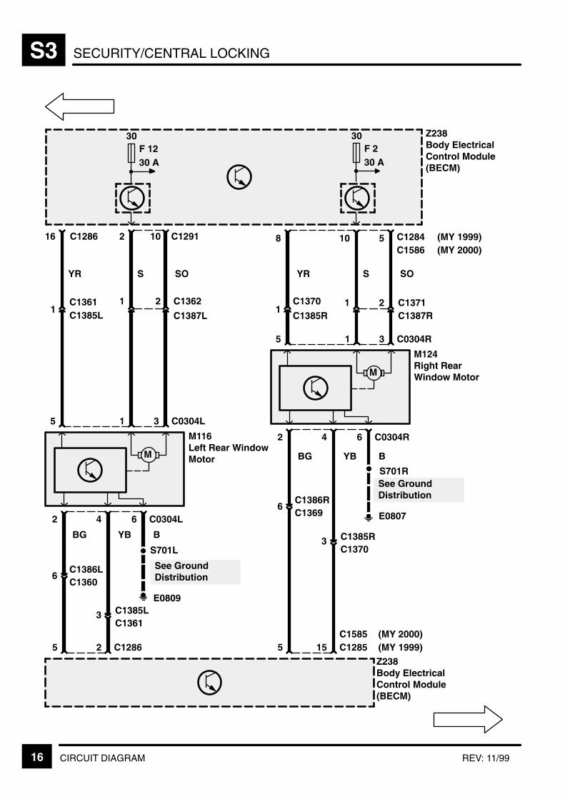
SECURITY/CENTRAL LOCKINGS3
16 CIRCUIT DIAGRAM REV: 11/99
Z238Body ElectricalControl Module(BECM)
30F 1230 A
3C1361C1385L
S
2
1
C1387L
C1362
YR
16
1
3 C0304L15
M116Left Rear WindowMotorM
42
YBBG
5
6
6 C0304L
Z238Body ElectricalControl Module(BECM)
2 C1286
C1286 10
SO
C1385LC1361 2
C1360C1386L
SO
5 C1284
2C1387RC1371
S
10
1
YR
8
1C1385R
C1370
S701L
E0809
3 C0304R15
M124Right RearWindow MotorM
42 6 C0304R
B
3C1370C1385R
YBBG
5
6
15 C1285
C1369C1386R
S701R
E0807
B
30F 230 A
C1291
See GroundDistribution
See GroundDistribution
C1585(MY 1999)(MY 2000)
C1586 (MY 2000)(MY 1999)

SECURITY/CENTRAL LOCKING S3
17CIRCUIT DIAGRAM
C1429
Z252Left SeatOutstation
1
C1429
Z238Body ElectricalControl Module(BECM)
4
PW
C0877
Z238Body ElectricalControl Module(BECM)
4
5
10
BW
7
2
OW
2
7
RW
12
3
LGW
C1430
Z258Right SeatOutstation
1
C1430
8 C1277
P
5
BO
7
5
O
2
1
R
12
6
LG
With LeftMemory Seatand Right Non–Memory Seat
With RightMemory Seatand Left Non–Memory Seat
With LeftMemory Seatand Right Non–Memory Seat
With RightMemory Seatand Left Non–Memory Seat
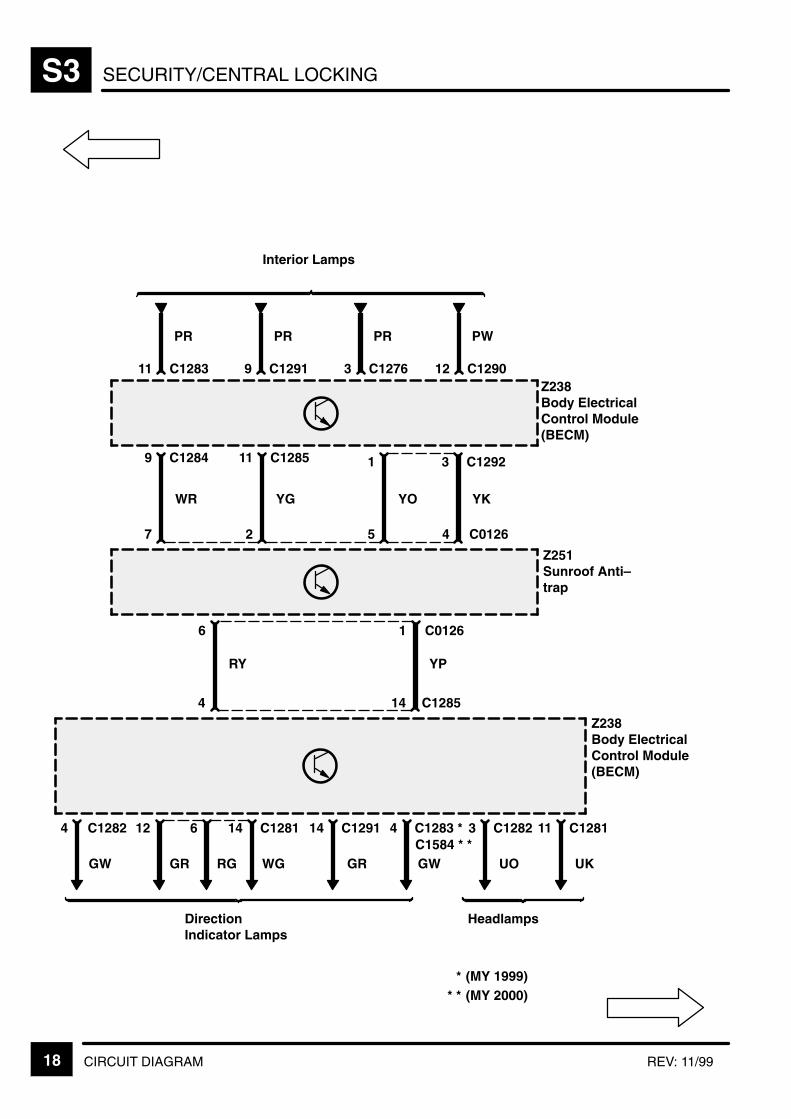
SECURITY/CENTRAL LOCKINGS3
18 CIRCUIT DIAGRAM REV: 11/99
C0126
Z251Sunroof Anti–trap
4527
C01266
PW
12 C1290Z238Body ElectricalControl Module(BECM)
3 C1292
YK
PR
3 C1276
PR
9 C1291
PR
11 C1283
9 C1284
WR
11 C1285
YG
1
YO
C1285
Z238Body ElectricalControl Module(BECM)
4
4 C1282
GW
RY
1
14
YP
11 C1281
UK
3 C1282
UO
4 C1283 *
GW
14 C1291
GR
14 C1281
WG
6
RG
12
GR
HeadlampsDirectionIndicator Lamps
Interior Lamps
C1584 * *
(MY 2000)(MY 1999)*
* *
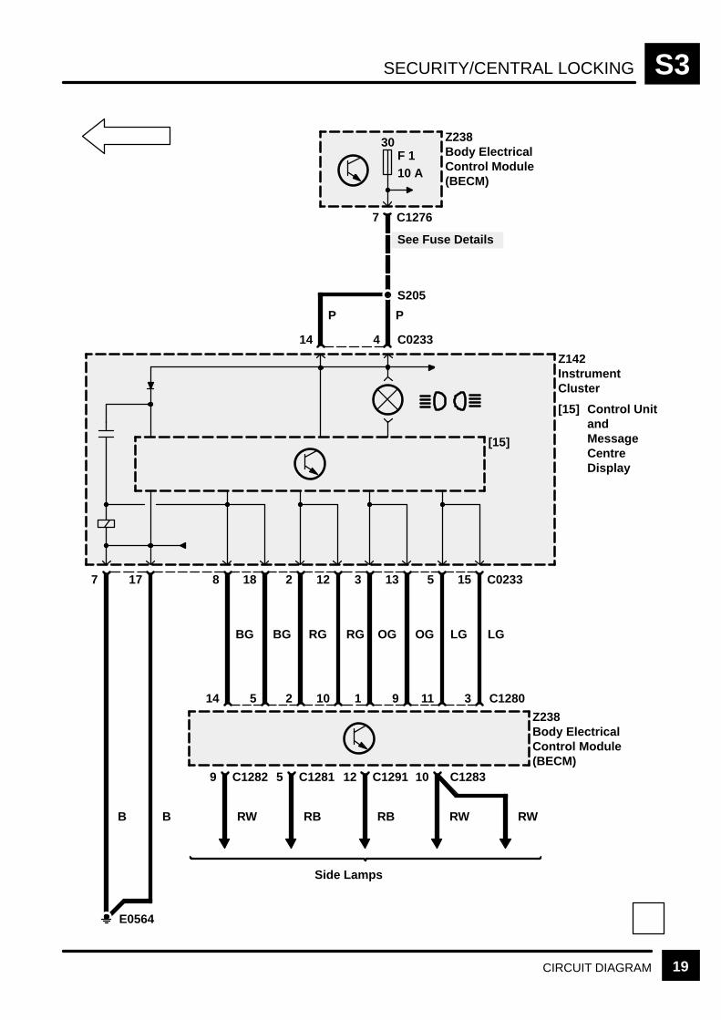
SECURITY/CENTRAL LOCKING S3
19CIRCUIT DIAGRAM
30F 110 A
Z238Body ElectricalControl Module(BECM)
7 C1276
See Fuse Details
S205
P
4 C023314
P
Z142InstrumentCluster
[15] Control UnitandMessageCentreDisplay
15 C02335133122188177
LG
3 C1280
LG
11
OG
9
OG
1
RG
10
RG
2
BG
5
BG
14
BB
E0564
Z238Body ElectricalControl Module(BECM)
[15]
9 C1282
RW
5 C1281
RB
12 C1291
RB
10 C1283
RW RW
Side Lamps


POWER DISTRIBUTION Y1
1CIRCUIT DIAGRAMREV: 08/99
P125aEngineCompartmentFuse Box
[19] Engine MainControl Relay
RL19
[19]
Not used
Shorting Link 5
Diesel
Not used
Petrol
E0560
K Y1-2
B+30K136Starter Solenoid
Z106Generator
Z135Glow Plug TimerUnit
Diesel
2
R
R
R
B
P104Battery
30
See GroundDistribution
5
3
F Y1-515
1
C0632
C0192
C0045
C0823C0631
DieselPetrol
C0183C0226
DieselPetrol
L Y1-2
Diesel
R
Petrol
R
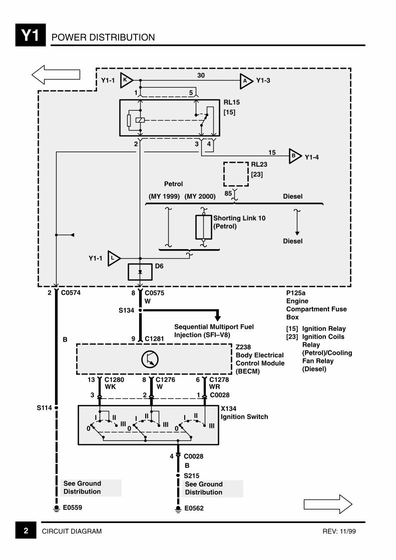
POWER DISTRIBUTIONY1
2 CIRCUIT DIAGRAM REV: 11/99
P125aEngineCompartment FuseBox
[15] Ignition Relay[23] Ignition Coils
Relay(Petrol)/CoolingFan Relay(Diesel)
RL15
[15]
15
30
B Y1-4
Z238Body ElectricalControl Module(BECM)
X134Ignition Switch
A Y1-3
I IIIII
I IIIII0
I II
III0
4
2 3 4
1 5
6 C127813 C1280 8 C1276
3 2 1WK W WR
C0028
B
8 C0575
9 C1281
W
See GroundDistribution
Sequential Multiport FuelInjection (SFI–V8)
D6
C0028
KY1-1
LY1-1
2 C0574
S134
E0562
S215See GroundDistribution
E0559
S114
B
0
RL23
[23]
85
Shorting Link 10(Petrol)
Diesel
(MY 2000)(MY 1999)
Petrol
Diesel
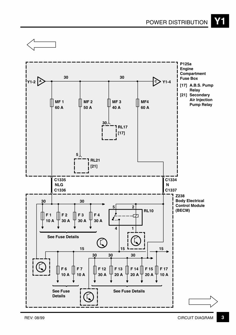
POWER DISTRIBUTION Y1
3CIRCUIT DIAGRAMREV: 08/99
RL21
[21]
AY1-2
MF 160 A
MF460 A
C Y1-4
MF 250 A
30
MF 340 A
RL17
[17]
5
Z238Body ElectricalControl Module(BECM)
F 110 A
F 230 A
F 330 A
F 430 A
F 610 A
F 1230 A
F 1320 A
F 1420 A
F 1710 A
F 710 A
F 1520 A
30
P125aEngineCompartmentFuse Box
[17] A.B.S. PumpRelay
[21] SecondaryAir InjectionPump Relay
15
5 2
4 1
RL10
15
See FuseDetails
NLG N
See Fuse Details
See Fuse Details
30
3030
30 3030
15
C1334
C1337
C1335
C1336
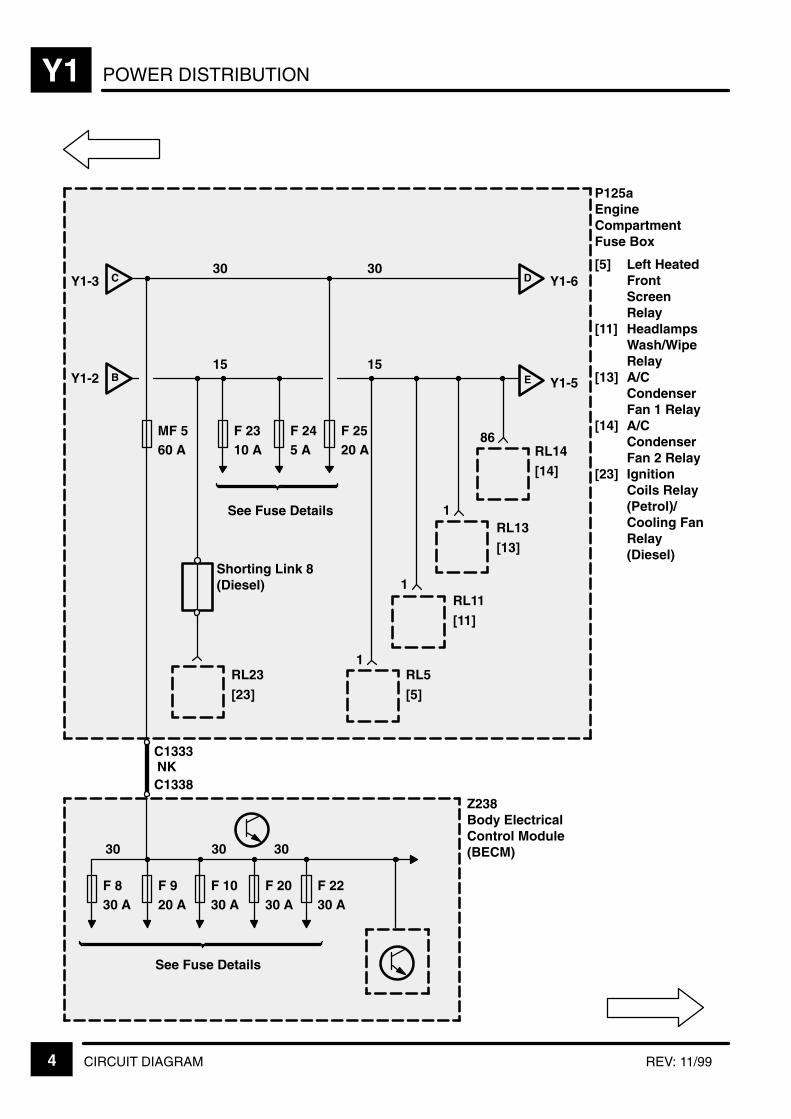
POWER DISTRIBUTIONY1
4 CIRCUIT DIAGRAM REV: 11/99
30
F 830 A
Z238Body ElectricalControl Module(BECM)
F 920 A
F 1030 A
F 2030 A
F 2230 A
See Fuse Details
CY1-3
BY1-2
F 2310 A
F 245 A
See Fuse Details
1
1
1
86
D Y1-6
E Y1-5
RL5
[5]
RL11
[11]
RL13
[13]
RL14
[14]
MF 560 A
30
F 2520 A
15 15
F 830 A
NK
30 3030
P125aEngineCompartmentFuse Box
[5] Left HeatedFrontScreenRelay
[11] HeadlampsWash/WipeRelay
[13] A/CCondenserFan 1 Relay
[14] A/CCondenserFan 2 Relay
[23] IgnitionCoils Relay(Petrol)/Cooling FanRelay(Diesel)
C1333
C1338
Shorting Link 8(Diesel)
RL23
[23]

POWER DISTRIBUTION Y1
5CIRCUIT DIAGRAMREV: 08/99
P125aEngineCompartmentFuse Box[17] A.B.S. Pump
Relay[21] Secondary
Air InjectionPump Relay
I Y1-6FY1-1
G Y1-6EY1-4
F 2620 A
See Fuse Details
15
85RL17
[17]
2
J
J1-7 Petrol
RL21
[21]

POWER DISTRIBUTIONY1
6 CIRCUIT DIAGRAM REV: 09/2001
P125aEngineCompartmentFuse BoxDY1-4
GY1-5
See Fuse Details
H
Y1-7
F 2710 A
F 2830 A
F 2910 A
F 3030 A
F 3130 A
F 3230 A
F 335 A
F 3410 A
See Fuse Details
F 3510 A
F 3630 A
F 3730 A
F3830 A
F 3920 A
F 4040 A
F 4120 A
F 4210 A
F 4330 A
F 4430 A
Y1-8
30 30
3030
15
Petrol
Diesel
IY1-515
15
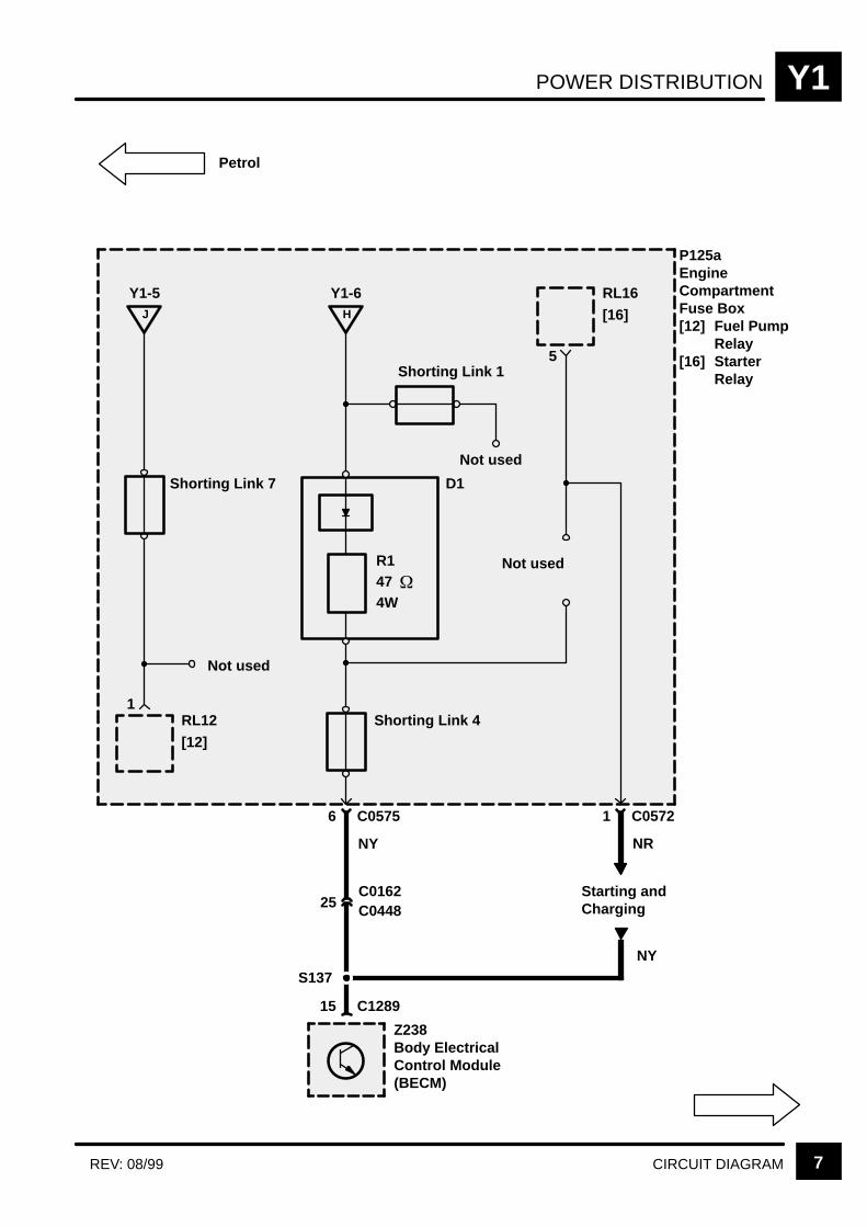
POWER DISTRIBUTION Y1
7CIRCUIT DIAGRAMREV: 08/99
47
P125aEngineCompartmentFuse Box[12] Fuel Pump
Relay[16] Starter
Relay
1RL12
[12]
Shorting Link 7
J
Y1-5
Not used
RL16
[16]
5
1 C0572
NR
Starting andCharging
Petrol
H
Y1-6
Not used
Not used
Shorting Link 4
R1
6 C0575
NY
Shorting Link 1
D1
4W
NY
S137
25C0162
Z238Body ElectricalControl Module(BECM)
15 C1289
C0448
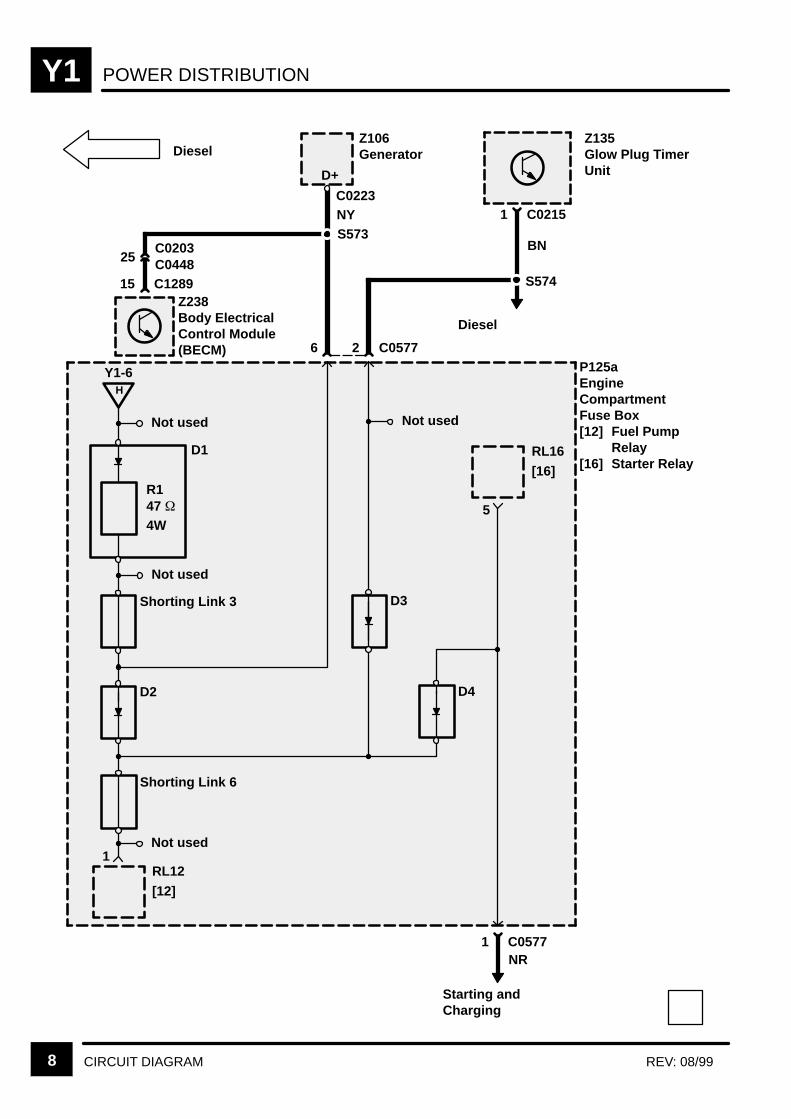
POWER DISTRIBUTIONY1
8 CIRCUIT DIAGRAM REV: 08/99
P125aEngineCompartmentFuse Box[12] Fuel Pump
Relay[16] Starter Relay
1RL12
[12]
H
Y1-6
5
RL16
[16]
Not used
6 2 C0577
Z238Body ElectricalControl Module(BECM)
Z135Glow Plug TimerUnit
S574
Z106Generator
S573
D+
Diesel
Starting andCharging
NY
BN
NR
D1
D3
25C0203C0448
Diesel
Not used
Not used
D2
Not used
D4
Shorting Link 3
Shorting Link 6
R1
1 C0215
15 C1289
C0223
47 4W
1 C0577
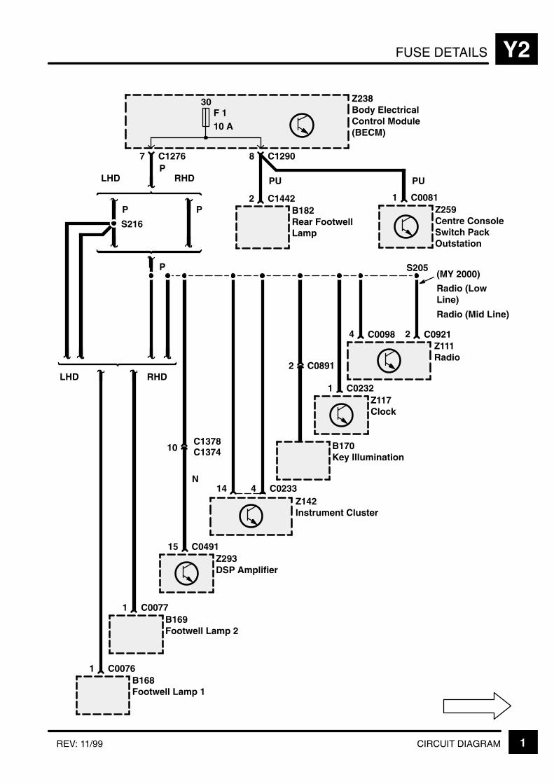
FUSE DETAILS Y2
1CIRCUIT DIAGRAMREV: 11/99
30F 110 A
7 C1276
S216
Z238Body ElectricalControl Module(BECM)
PLHD RHD
P P
8 C1290
PU
2 C1442B182Rear FootwellLamp
PU
1 C0081Z259Centre ConsoleSwitch PackOutstation
P
LHD RHD
B168Footwell Lamp 1
B169Footwell Lamp 2
14Z142Instrument Cluster
4 C0233
1 C0232Z117Clock
B170Key Illumination
2 C0891
S205
1 C0077
C00761
4Z111Radio
C0098 2 C0921
(MY 2000)
Radio (LowLine)
Radio (Mid Line)
15 C0491Z293DSP Amplifier
10C1378C1374
N
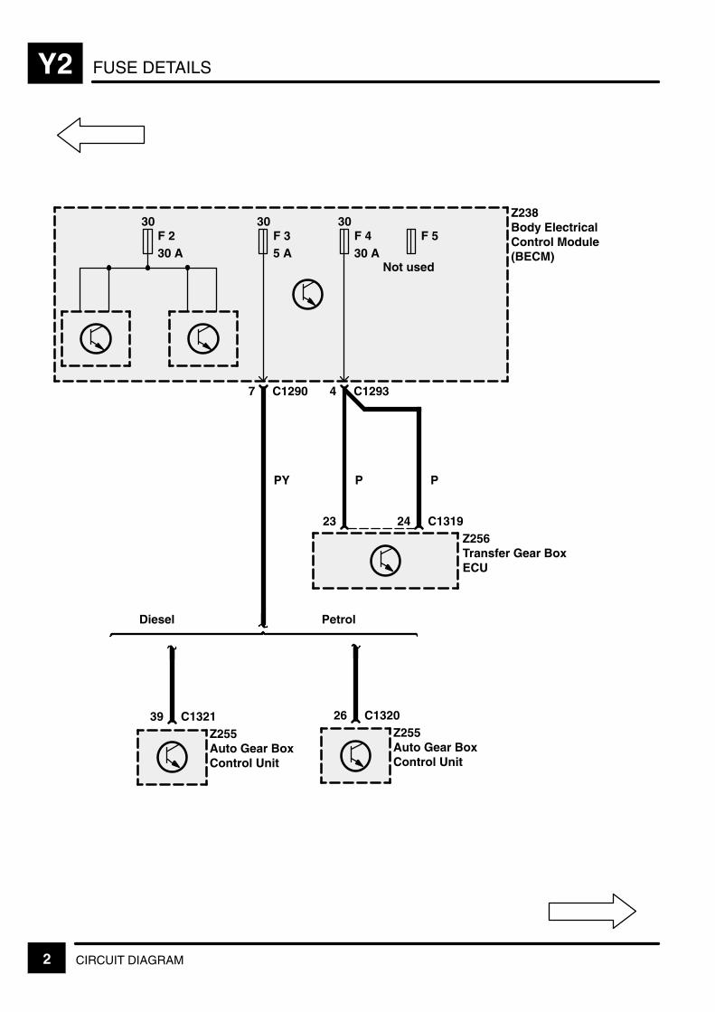
FUSE DETAILSY2
2 CIRCUIT DIAGRAM
Z238Body ElectricalControl Module(BECM)
4 C1293
P
23Z256Transfer Gear BoxECU
P
30F 230 A
30F 35 A
7 C1290
PY
24 C1319
30F 430 A
F 5
Not used
Z255Auto Gear BoxControl Unit
39 C1321Z255Auto Gear BoxControl Unit
26 C1320
Diesel Petrol
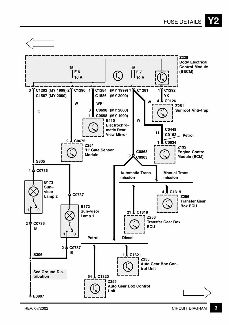
FUSE DETAILS Y2
3CIRCUIT DIAGRAMREV: 08/2002
(MY 1999) 2
15F 610 A
Z238Body ElectricalControl Module(BECM)
C1290
Petrol
54 C1320Z255Auto Gear Box ControlUnit
Diesel
1 C1321
1 C1284
WPW
2 C0675Z254’H’ Gate SensorModule
B110Electrochro-matic RearView Mirror
1 C0698
1 C1281
5 C0903
Automatic Trans-mission
21 C1319Z256Transfer Gear BoxECU
Manual Trans-mission
4 C1319Z256Transfer GearBox ECU
15F 710 A
W
C0868
Z255Auto Gear Box Con-trol Unit
1 C0634Z132Engine ControlModule (ECM)
W
11C0448C0162 Petrol
C0698(MY 1999)(MY 2000)3
YK4 C1292
Z251Sunroof Anti–trap
4 C0126C1586 (MY 2000)
(MY 1999)3 C1292
G
B
S306
See Ground Dis-tribution
E0807
01
S305
1 C0736
2 C0736
B173Sun–visorLamp 2
B172Sun–visorLamp 1
B
1 C0737
2 C0737
C1587 (MY 2000)
01

FUSE DETAILSY2
4 CIRCUIT DIAGRAM REV: 11/99
Z238Body ElectricalControl Module(BECM)
30F 830 A
RL7
30F 920 A
PB
10 C1406Z244Right Front DoorOutstation
PB
10 C1580Z243Left Front DoorOutstation
3 C1365C1384L
3 C1372C1384R
C1586 (MY 2000)(MY 1999)C12848 C1291 2
(MY 1999)(MY 2000)C1368
C1578L (MY 2000)(MY 1999)
(MY 1999)(MY 2000)C1583
C1578R (MY 2000)(MY 1999)
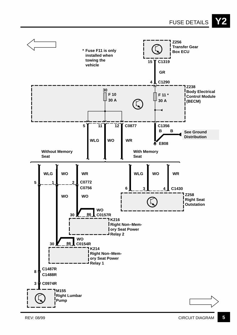
FUSE DETAILS Y2
5CIRCUIT DIAGRAMREV: 08/99
Z238Body ElectricalControl Module(BECM)
30F 1030 A
3 C0974R
M155Right LumbarPump
12 C0877
3
Z258Right SeatOutstation
11
5
5
WO WRWLG
WLG
8C1487RC1488R
1
WO
30 C0154RK214Right Non–Mem-ory Seat PowerRelay 1
86
2 C0772C0756
WR
30 C0157RK216Right Non–Mem-ory Seat PowerRelay 2
86
WO WO
WO
WO
Without MemorySeat
WLG WO WR
With MemorySeat
6 4 C1430
F 11 *30 A
Z256Transfer GearBox ECU
15 C1319
4 C1290
E808
See GroundDistribution
B
* Fuse F11 is onlyinstalled whentowing thevehicle
B
GR
C1356
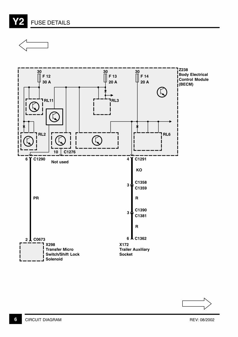
FUSE DETAILSY2
6 CIRCUIT DIAGRAM REV: 08/2002
Z238Body ElectricalControl Module(BECM)
30F 1230 A
RL11
4 C1291
3C1358C1359
RL2
30F 1320 A
30F 1420 A
RL6
KO
R
3C1390C1381
R
X172Trailer AuxiliarySocket
6 C1362
RL3
6 C1290
PR
C0673X298Transfer MicroSwitch/Shift LockSolenoid
2
Not used
10 C1276

FUSE DETAILS Y2
7CIRCUIT DIAGRAMREV: 11/99
(MY 2000)(MY 1999)
C03583Z250Alarm R.F.Antenna Module
P
C06171M132Tailgate LockActuator
11C0789
C01201B174Rear LoadSpace Lamp
C03573B107Front InteriorRoof Lamp
B179Right InteriorLights
1 C03562C0608
C0492L5Z245Left Rear DoorSpeakerAmplifier
C08346Z176SubwooferAmplifier
B180Left InteriorLights
30F 1520 A
6C1387
1 C0355C1362
PC128317 C12916
RL8
Z238Body ElectricalControl Module(BECM)
C0697 C0495
W
S362
X325Home LinkConnector
2 C0992
S302
C1584
4 (MY 2000)C04915
Z293DSP Amplifier
C0492R5Z246Right Rear DoorSpeakerAmplifier
6 C1371C1387
P
C12844C1586
(MY 1999)(MY 2000)
S359 (MY 1999)
(MY 2000)
(MY 2000)

FUSE DETAILSY2
8 CIRCUIT DIAGRAM
W
C00751X168Stop LampSwitch
F 18
C12769
Z238Body ElectricalControl Module(BECM)
F 16
Not used
15F 1710 A
F 19
Not used
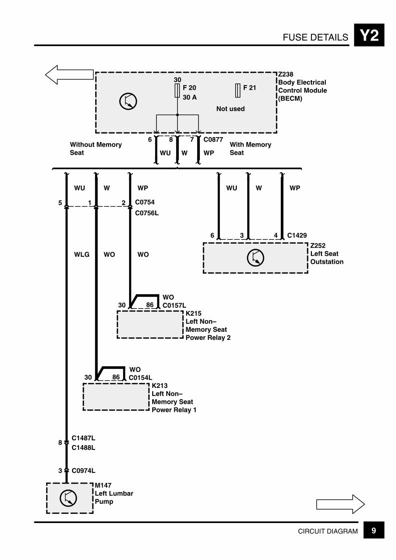
FUSE DETAILS Y2
9CIRCUIT DIAGRAM
Z238Body ElectricalControl Module(BECM)
30F 2030 A
3 C0974L
M147Left LumbarPump
7 C0877
3
Z252Left SeatOutstation
8
5
6
W WPWU
WU
8C1487LC1488L
1
W
30 C0154LK213Left Non–Memory SeatPower Relay 1
86
2 C0754
C0756L
WP
30 C0157LK215Left Non–Memory SeatPower Relay 2
86
WO WO
WO
WO
Without MemorySeat
WU W WP
With MemorySeat
6 4 C1429
F 21
Not used
WLG
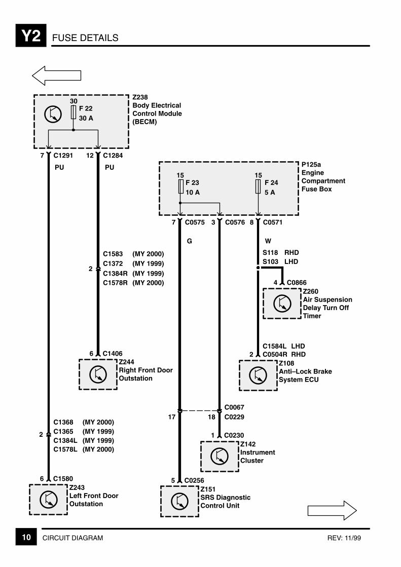
FUSE DETAILSY2
10 CIRCUIT DIAGRAM REV: 11/99
C13652
PU
Z238Body ElectricalControl Module(BECM)
C12917
30F 2230 A
C128412
PU P125aEngineCompartmentFuse Box
C05757
15F 2310 A
C05718
15F 245 A
WG
C15806Z243Left Front DoorOutstation
C14066Z244Right Front DoorOutstation
C0504R2Z108Anti–Lock BrakeSystem ECU
C08664Z260Air SuspensionDelay Turn OffTimer
S118S103
RHDLHDC1372
2
C1584L LHDRHD
C02565Z151SRS DiagnosticControl Unit
C02301Z142InstrumentCluster
17 C022918C0067
3 C0576
C1384L
C1384R
C1368(MY 1999)(MY 2000)
C1578L(MY 1999)(MY 2000)
C1578R(MY 1999)(MY 2000)
C1583(MY 1999)(MY 2000)

FUSE DETAILS Y2
11CIRCUIT DIAGRAM
30F 2520 A
1 5 5RL1
[1]
RL11
[11]
P125aEngineCompartmentFuse Box
[1] Front WiperControl Relay
[8] Front WiperInterval Relay
[11] HeadlampsWash/WipeRelay
C08541M157Right HeadlampWiper Motor
1RL8
[8]
C08531M156Left HeadlampWiper Motor
4 C05705
NUNU
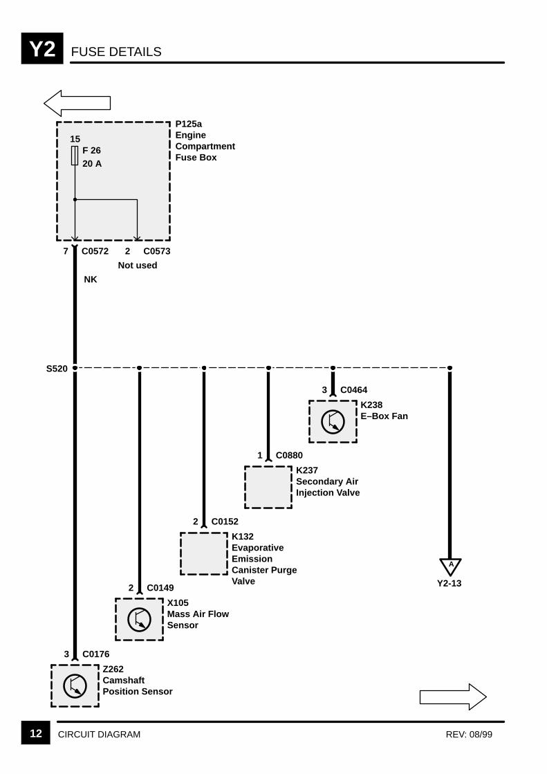
FUSE DETAILSY2
12 CIRCUIT DIAGRAM REV: 08/99
15F 2620 A
P125aEngineCompartmentFuse Box
NK
Z262CamshaftPosition Sensor
3 C0176
X105Mass Air FlowSensor
2 C0149
K132EvaporativeEmissionCanister PurgeValve
2 C0152
K237Secondary AirInjection Valve
1 C0880
K238E–Box Fan
3 C0464
7 C0572 2 C0573
S520
A
Y2-13
Not used

FUSE DETAILS Y2
13CIRCUIT DIAGRAM
X139Left HeatedOxygen Sensor
4
X160Right HeatedOxygen Sensor
X289Left HeatedOxygen Sensor(Post Catalyst)
X290Right HeatedOxygen Sensor(Post Catalyst)
S509
A
Y2-12
NAS
C0644
4 C0645
4 C0643
4 C0642
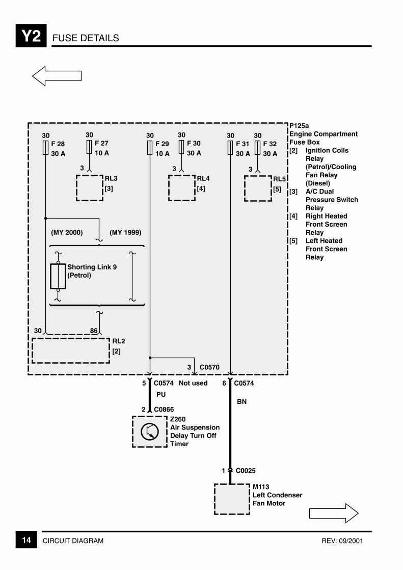
FUSE DETAILSY2
14 CIRCUIT DIAGRAM REV: 09/2001
30 86
RL2
[2]
30F 2830 A
30F 3230 A
3RL5
[5]
P125aEngine CompartmentFuse Box[2] Ignition Coils
Relay(Petrol)/CoolingFan Relay(Diesel)
[3] A/C DualPressure SwitchRelay
[4] Right HeatedFront ScreenRelay
[5] Left HeatedFront ScreenRelay
30F 2710 A
3
RL3
[3]
30F 2910 A
PU
5
C0866Z260Air SuspensionDelay Turn OffTimer
2
C0574
3 C0570
Not used
(MY 2000) (MY 1999)
Shorting Link 9(Petrol)
30F 3030 A
3RL4
[4]
1 C0025
M113Left CondenserFan Motor
30F 3130 A
BN
6 C0574

FUSE DETAILS Y2
15CIRCUIT DIAGRAM
30F 3430 A
N W
62
Z272Battery BackedUp AlarmSounder
1
RL7
[7]
3
P125aEngineCompartment FuseBox[7] Auxiliary
Power 2 Relay
X271Ride HeightSwitch
S136
C0666
Except NAS
30F 335 A
4 C0574 8 C0573
15F 3510 A
3 C0575
C0067
16 C0040
3 C0893
Z253HeatingVentilation andAir ConditioningControl Unit(HEVAC)
3 C0792
X209Air SuspensionInhibit Switch
4 C0849
1Z272Battery BackedUp AlarmSounder
2C0666
C0229
X318Data LinkConnector(OBDII)
N
Except NAS
C0067C0229
2
S211
C0540
C0731
C0540
C0731
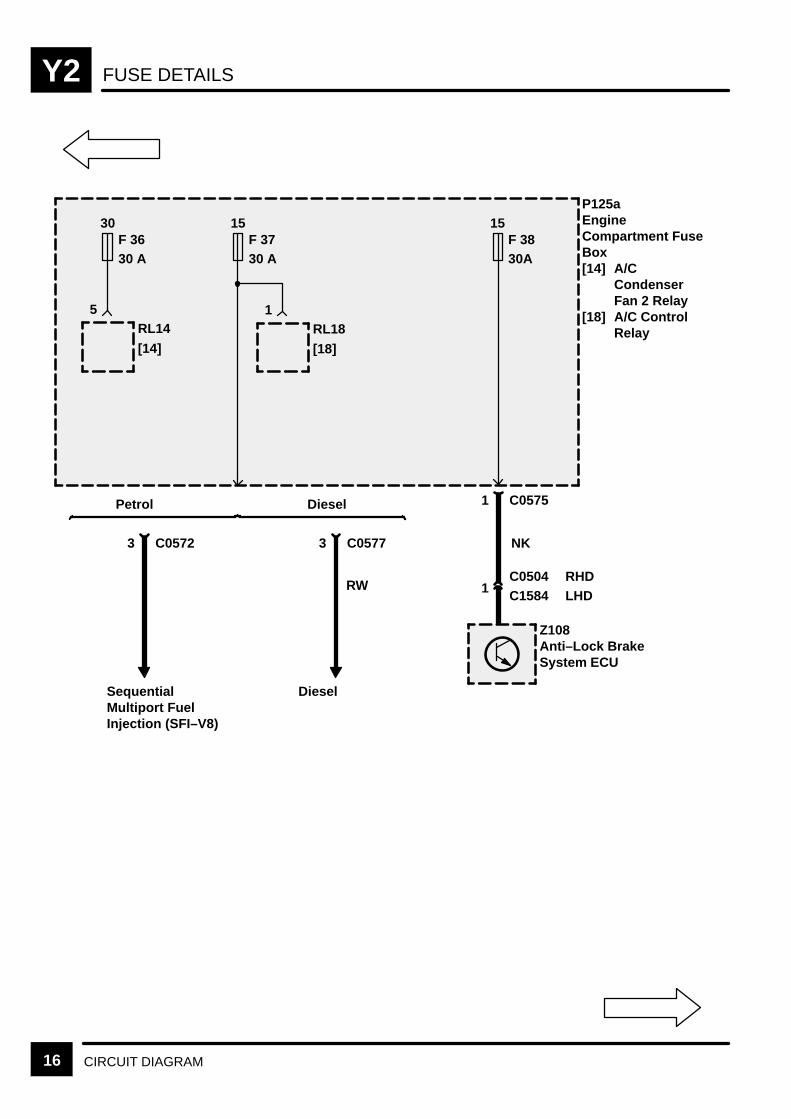
FUSE DETAILSY2
16 CIRCUIT DIAGRAM
30F 3630 A
15F 3730 A
1 C0575
NK
1 C1584
Z108Anti–Lock BrakeSystem ECU
5RL14
[14]
15F 3830A
P125aEngineCompartment FuseBox[14] A/C
CondenserFan 2 Relay
[18] A/C ControlRelay
1RL18
[18]
C0504LHDRHD
3 C0577
Diesel
RW
3 C0572
SequentialMultiport FuelInjection (SFI–V8)
Petrol Diesel
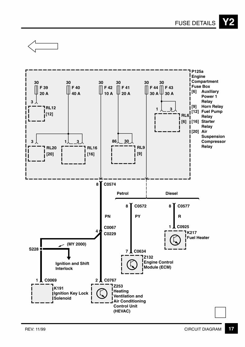
FUSE DETAILS Y2
17CIRCUIT DIAGRAMREV: 11/99
30F 3920 A
30F 4040 A
30F 4120 A
30F 4210 A
30F 4330 A
30F 4430 A
86
RL9
[9]
PN
C0574
8 C0572
PY
7 C0634
3RL12
[12]
30
1
RL6
[6]
3
Z132Engine ControlModule (ECM)
2 C0767Z253HeatingVentilation andAir ConditioningControl Unit(HEVAC)
P125aEngineCompartmentFuse Box[6] Auxiliary
Power 1Relay
[9] Horn Relay[12] Fuel Pump
Relay[16] Starter
Relay[20] Air
SuspensionCompressorRelay
3
RL20
[20]
1
RL16
[16]
3
8
4C0067
1 C0069
K191Ignition Key LockSolenoid
8 C0577
R
1 C0925K217Fuel Heater
Petrol Diesel
C0229
S228
Ignition and ShiftInterlock
(MY 2000)
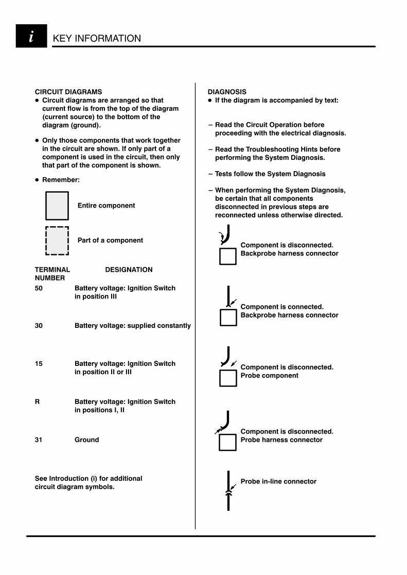
KEY INFORMATIONi
!"
#$ % &'( ' )
*$ % &'( + %
,# % &'( ' )
% &'( ' )
-
*, !+
!
+ ' '
+ .) . . '
/+ +0 .
' /'+0
"% ) '
+ ) . % .
+ +- %
. )
(
.
!"
. ' % 1(
2 + " .
' ) '
2 +' 3 .
.' % '
2 .) % '
2 4 .' % '-
&+
+ )
+ /0 .
+ ' %

Y5GROUND DISTRIBUTION
1REV: 11/99
GROUND AND SPLICE INDEX
Ground Page
E0119 Y5–2. . . . . . . . . . . . . . . . . . . . . . . . . . .
E0360 Y5–2. . . . . . . . . . . . . . . . . . . . . . . . . . .
E0361 Y5–2. . . . . . . . . . . . . . . . . . . . . . . . . . .
E0500 Y5–2. . . . . . . . . . . . . . . . . . . . . . . . . . .
E0556 Y5–3. . . . . . . . . . . . . . . . . . . . . . . . . . .
E0556 D Y5–6. . . . . . . . . . . . . . . . . . . . . . . . .
E0557 Y5–5. . . . . . . . . . . . . . . . . . . . . . . . . . .
E0558 Y5–2. . . . . . . . . . . . . . . . . . . . . . . . . . .
E0559 Y5–9. . . . . . . . . . . . . . . . . . . . . . . . . . .
E0560 Y5–11. . . . . . . . . . . . . . . . . . . . . . . . . . .
E0561 Y5–5. . . . . . . . . . . . . . . . . . . . . . . . . . .
E0562 Y5–14. . . . . . . . . . . . . . . . . . . . . . . . . . .
E0563 Y5–15. . . . . . . . . . . . . . . . . . . . . . . . . . .
E0563 Y5–15. . . . . . . . . . . . . . . . . . . . . . . . . . .
E0564 Y5–15. . . . . . . . . . . . . . . . . . . . . . . . . . .
E0565 Y5–16,17. . . . . . . . . . . . . . . . . . . . . . . . . . .
E0807 Y5–18,19. . . . . . . . . . . . . . . . . . . . . . . . . . .
E0808 Y5–21. . . . . . . . . . . . . . . . . . . . . . . . . . .
E0809 Y5–22,23. . . . . . . . . . . . . . . . . . . . . . . . . . .
E0810 Y5–24. . . . . . . . . . . . . . . . . . . . . . . . . . .
E0811 Y5–24. . . . . . . . . . . . . . . . . . . . . . . . . . .
E0822 Y5–11. . . . . . . . . . . . . . . . . . . . . . . . . . .
E0910 Y5–24. . . . . . . . . . . . . . . . . . . . . . . . . . .
E1347 Y5–29. . . . . . . . . . . . . . . . . . . . . . . . . . .
E1348 Y5–29. . . . . . . . . . . . . . . . . . . . . . . . . . .
E1351 Y5–30. . . . . . . . . . . . . . . . . . . . . . . . . . .
E1355 Y5–25. . . . . . . . . . . . . . . . . . . . . . . . . . .
E1398 Y5–27. . . . . . . . . . . . . . . . . . . . . . . . . . .
E1412 Y5–28. . . . . . . . . . . . . . . . . . . . . . . . . . .
E1413 Y5–28. . . . . . . . . . . . . . . . . . . . . . . . . . .
E1431 Y5–31. . . . . . . . . . . . . . . . . . . . . . . . . . .
E1547 Y5–11. . . . . . . . . . . . . . . . . . . . . . . . . . .
Splice Page
S101 Y5–4, 5. . . . . . . . . . . . . . . . . . . . . . . . . . . .
S110 Y5–5. . . . . . . . . . . . . . . . . . . . . . . . . . . .
S111 Y5–10,11. . . . . . . . . . . . . . . . . . . . . . . . . . . . .
S113 Y5–3. . . . . . . . . . . . . . . . . . . . . . . . . . . .
S114 Y5–9. . . . . . . . . . . . . . . . . . . . . . . . . . . .
S115 Y5–7. . . . . . . . . . . . . . . . . . . . . . . . . . . .
S122 Y5–11. . . . . . . . . . . . . . . . . . . . . . . . . . . .
S207 Y5–14. . . . . . . . . . . . . . . . . . . . . . . . . . . .
S208 Y5–13,14. . . . . . . . . . . . . . . . . . . . . . . . . . . .
S215 Y5–12. . . . . . . . . . . . . . . . . . . . . . . . . . . .
S219 Y5–29. . . . . . . . . . . . . . . . . . . . . . . . . . . .
S301 Y5–16. . . . . . . . . . . . . . . . . . . . . . . . . . . .
S304 Y5–18. . . . . . . . . . . . . . . . . . . . . . . . . . . .
S306 Y5–18. . . . . . . . . . . . . . . . . . . . . . . . . . . .
S307 Y5–19. . . . . . . . . . . . . . . . . . . . . . . . . . . .
S355 Y5–22. . . . . . . . . . . . . . . . . . . . . . . . . . . .
S356 Y5–22. . . . . . . . . . . . . . . . . . . . . . . . . . . .
S361 Y5–23. . . . . . . . . . . . . . . . . . . . . . . . . . . .
S506 Y5–25. . . . . . . . . . . . . . . . . . . . . . . . . . . .
S521 Y5–24. . . . . . . . . . . . . . . . . . . . . . . . . . . .
S527 Y5–25. . . . . . . . . . . . . . . . . . . . . . . . . . . .
S528 Y5–27. . . . . . . . . . . . . . . . . . . . . . . . . . . .
S530 Y5–24. . . . . . . . . . . . . . . . . . . . . . . . . . . .
S551 Y5–26. . . . . . . . . . . . . . . . . . . . . . . . . . . .
S571 Y5–6. . . . . . . . . . . . . . . . . . . . . . . . . . . .
S607 Y5–20,21. . . . . . . . . . . . . . . . . . . . . . . . . . . .
S611 Y5–20. . . . . . . . . . . . . . . . . . . . . . . . . . . .
S701R Y5–19. . . . . . . . . . . . . . . . . . . . . . . . . . .
S701L Y5–23. . . . . . . . . . . . . . . . . . . . . . . . . . .
S851 Y5–17. . . . . . . . . . . . . . . . . . . . . . . . . . . .
S852 Y5–17. . . . . . . . . . . . . . . . . . . . . . . . . . . .
S901 Y5–28. . . . . . . . . . . . . . . . . . . . . . . . . . . .

GROUND DISTRIBUTIONY5
2 CIRCUIT DIAGRAM REV: 08/99
Z103A.B.S. BoosterUnit
C15921
E0500
1
E0538
LHD
RHDC0362
RHD
LHD
Z111Radio
C00988
B
E0361
Z151SRS DiagnosticControl Unit
C02566
E0360
B
B108Heated FrontScreen
E0119
B

GROUND DISTRIBUTION Y5
3CIRCUIT DIAGRAM
B
Z108Anti–Lock BrakeSystem ECU
C050412
B
K163Air Valve Block
C087111
B
10
B
Z260Air SuspensionDelay Turn OffTimer
C08666
B
M107Front Wiper Motor
C15934
S113
E0556
LHD
RHD
RHDLHD
C0030 RHD
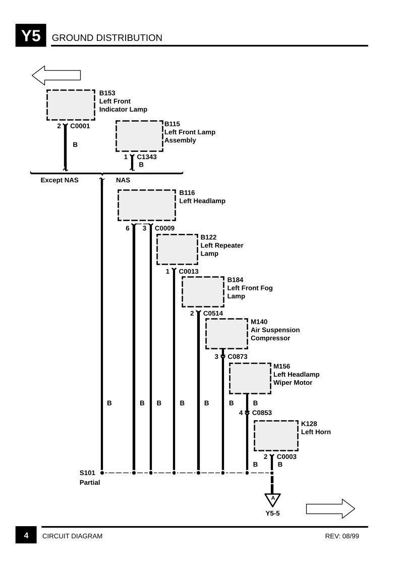
GROUND DISTRIBUTIONY5
4 CIRCUIT DIAGRAM REV: 08/99
B
B116Left Headlamp
C00093
B
6
B
B122Left RepeaterLamp
C00131
B
M140Air SuspensionCompressor
C08733
B
B184Left Front FogLamp
C05142
B
M156Left HeadlampWiper Motor
B
K128Left Horn
C00032
A
Y5-5
BC08534
S101
B
B115Left Front LampAssembly
C13431
B153Left FrontIndicator Lamp
C00012
B
B
Except NAS NAS
Partial
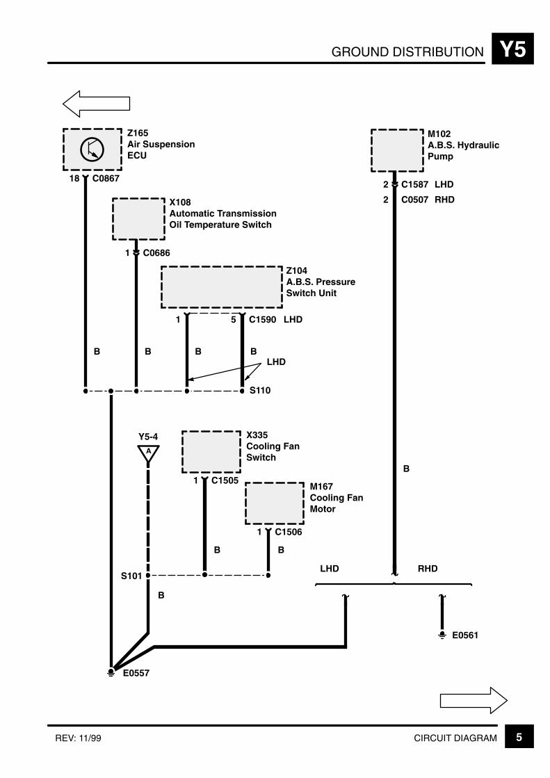
GROUND DISTRIBUTION Y5
5CIRCUIT DIAGRAMREV: 11/99
B
X108Automatic TransmissionOil Temperature Switch
C06861
S110
B
Z165Air SuspensionECU
C086718
B
Z104A.B.S. PressureSwitch Unit
1
B
C15905
B
M102A.B.S. HydraulicPump
C15872
C05072
LHD
LHD
RHD
E0557
B
E0561
LHD RHD
LHD
S101
A
Y5-4 X335Cooling FanSwitch
C15051M167Cooling FanMotor
C15061
B B
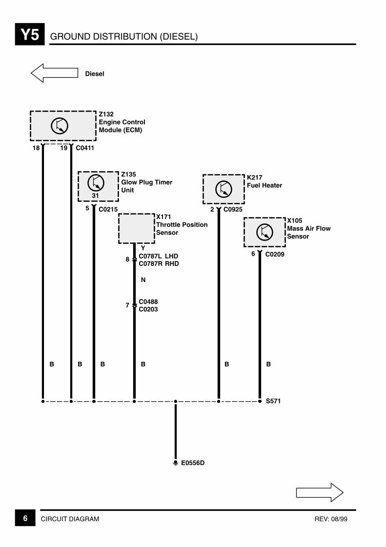
GROUND DISTRIBUTION (DIESEL)Y5
6 CIRCUIT DIAGRAM REV: 08/99
Z132Engine ControlModule (ECM)
18
B
C041119
B
S571
E0556D
K217Fuel Heater
C09252
B
Z135Glow Plug TimerUnit
C02155
B
X171Throttle PositionSensor
Y
B
C02037 C0488
C0787R8 C0787L LHD
RHD
31
Diesel
X105Mass Air FlowSensor
6
B
C0209
N

GROUND DISTRIBUTION Y5
7CIRCUIT DIAGRAMREV: 08/99
BP
5
BP
Z134Fuel PumpModule
C02053
X165Screen WashFluid LevelSwitch
A
Y5-9
BP
X114Engine CoolantTemperatureGauge Sensor
2
NY
C0040
X318Data LinkConnector(OBDII)
C02042PetrolDiesel
2 C0620
6C0203C0448
5C0229C0067
BP
S115
C0196D
Z132Engine ControlModule (ECM)
31
BN
6C0162C0448
C0636
BP
X110Bonnet Switch
C00072
Petrol Diesel
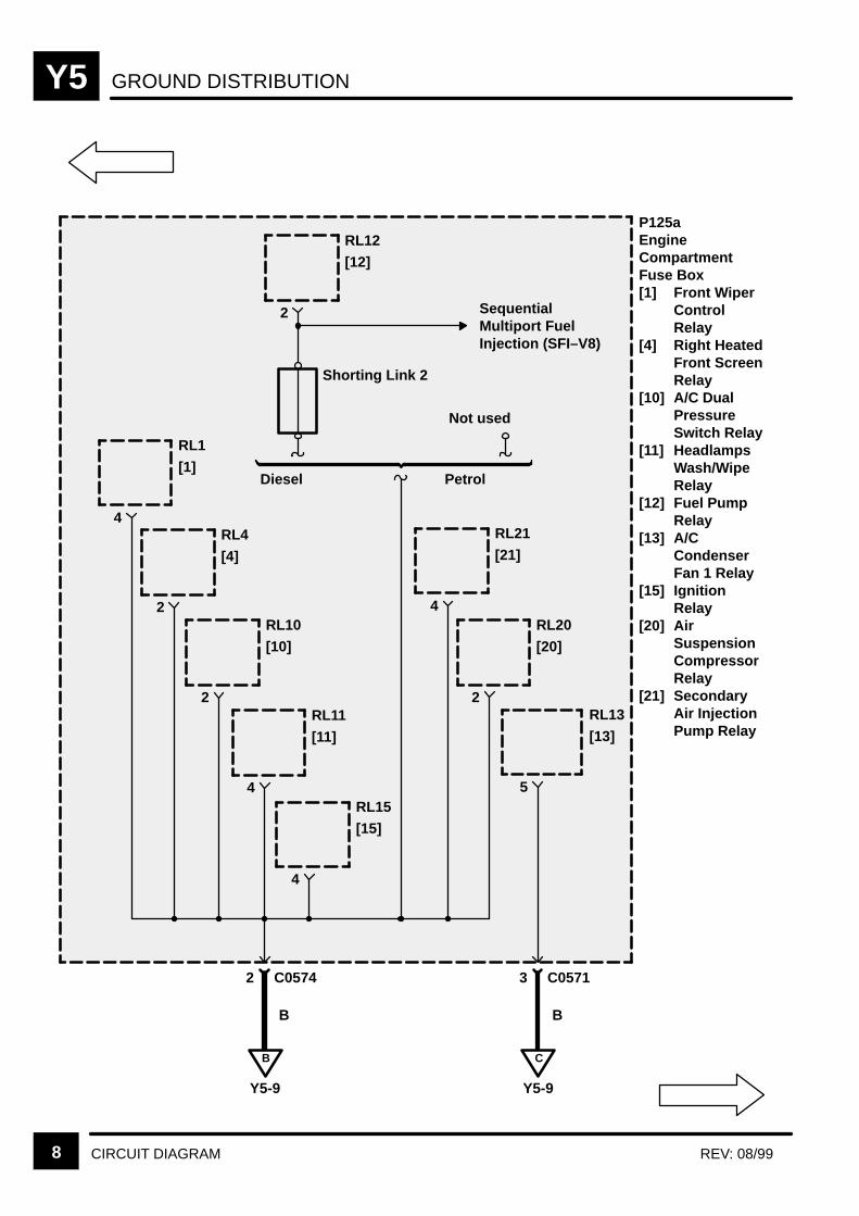
GROUND DISTRIBUTIONY5
8 CIRCUIT DIAGRAM REV: 08/99
2
B
Y5-9
P125aEngineCompartmentFuse Box[1] Front Wiper
ControlRelay
[4] Right HeatedFront ScreenRelay
[10] A/C DualPressureSwitch Relay
[11] HeadlampsWash/WipeRelay
[12] Fuel PumpRelay
[13] A/CCondenserFan 1 Relay
[15] IgnitionRelay
[20] AirSuspensionCompressorRelay
[21] SecondaryAir InjectionPump Relay
RL12
[12]
Shorting Link 2
4
RL1
[1]
2
RL4
[4]
2
RL10
[10]
4
RL11
[11]
4
RL15
[15]
5
RL13
[13]
2
RL20
[20]
Not used
C
Y5-9
C05742 C05713
B B
PetrolDiesel
4
RL21
[21]
SequentialMultiport FuelInjection (SFI–V8)

GROUND DISTRIBUTION Y5
9CIRCUIT DIAGRAM
B
C02054
B
Z108Anti–Lock BrakeSystem ECU
C158412
B
M107Front WiperMotor
C0030R4
B
B137Right RepeaterLamp
C00121
S114
C
Y5-8B
Y5-8
E0559
B B
Z134Fuel PumpModule
Z272Battery BackedUp AlarmSounder
C07314
B
With BatteryBacked Up AlarmSounder
Without BatteryBacked UpAlarm Sounder
2 C0520
Z171Alarm Sounder
BC00612
RHDLHD
A
Y5-7
C0520
PetrolC02043 Diesel
LHD

GROUND DISTRIBUTIONY5
10 CIRCUIT DIAGRAM
B
B130Right Headlamp
C00113
B
6
B
B183Right Front FogLamp
C05132
B
M121Right CondenserFan Motor
C02802
B
M157Right HeadlampWiper Motor
C08544
D
Y5-11
B154Right FrontIndicator Lamp
C13462
B128Right Front LampAssembly
C13451
B B
NASExcept NAS
B
K134Right Horn
C00042
B
S111 Partial
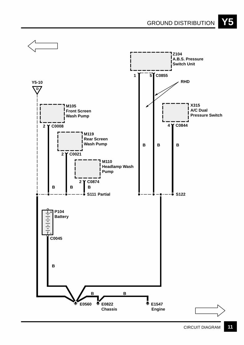
GROUND DISTRIBUTION Y5
11CIRCUIT DIAGRAM
B B
Z104A.B.S. PressureSwitch Unit
C085551
B
M105Front ScreenWash Pump
C00082
B
C08444
Chassis
Y5-10D
B
M119Rear ScreenWash Pump
C00212
B
M110Headlamp WashPump
C08742
S111
P104Battery
B
B B
E0560 E0822 E1547Engine
RHD
Partial
X315A/C DualPressure Switch
C0045
S122
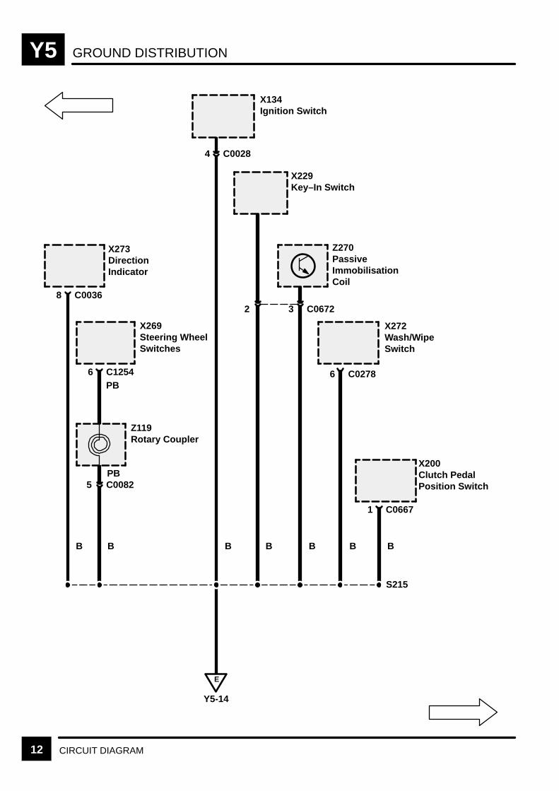
GROUND DISTRIBUTIONY5
12 CIRCUIT DIAGRAM
B
X229Key–In Switch
B
C00284
B
X273DirectionIndicator
C00368
B
X269Steering WheelSwitches
C12546
Z119Rotary Coupler
PB
C00825
X134Ignition Switch
B
C06723
B
X272Wash/WipeSwitch
X200Clutch PedalPosition Switch
C06671
B
S215
E
Y5-14
2
Z270PassiveImmobilisationCoil
PB
C02786
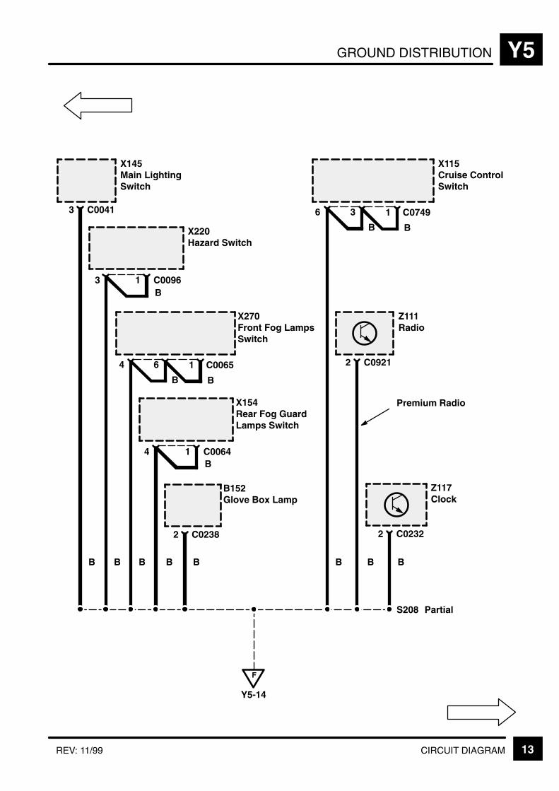
GROUND DISTRIBUTION Y5
13CIRCUIT DIAGRAMREV: 11/99
B
X145Main LightingSwitch
C00413
B
X220Hazard Switch
3 C00961B
B
X270Front Fog LampsSwitch
4 6
B
C00651
B
B
X154Rear Fog GuardLamps Switch
4 C00641B
B
B152Glove Box Lamp
C02382
B
Z117Clock
C02322
B
Z111Radio
C09212
B
X115Cruise ControlSwitch
3
B
C07491
B
S208 Partial
F
Y5-14
6
Premium Radio

GROUND DISTRIBUTIONY5
14 CIRCUIT DIAGRAM REV: 08/99
B
X271Ride HeightSwitch
C08937
B
B151Theft Alarm LED
C02402
F
Y5-13
B
X209Air SuspensionInhibit Switch
6 C08941B
B
Z253Heating Ventilationand AirConditioningControl Unit(HEVAC)
C07924
S208 Partial
B
Z249Cruise ControlConverter/In-verter Module
C0895D2
B
Z121Cruise ControlECU
C023918
E
Y5-12
B
X125Fuel FlapRelease Switch
C07481
B
K152Resistor
B
S207
Diesel Petrol
E0562
Partial
C00404
X318Data LinkConnector(OBDII)
Not installed onall vehicles
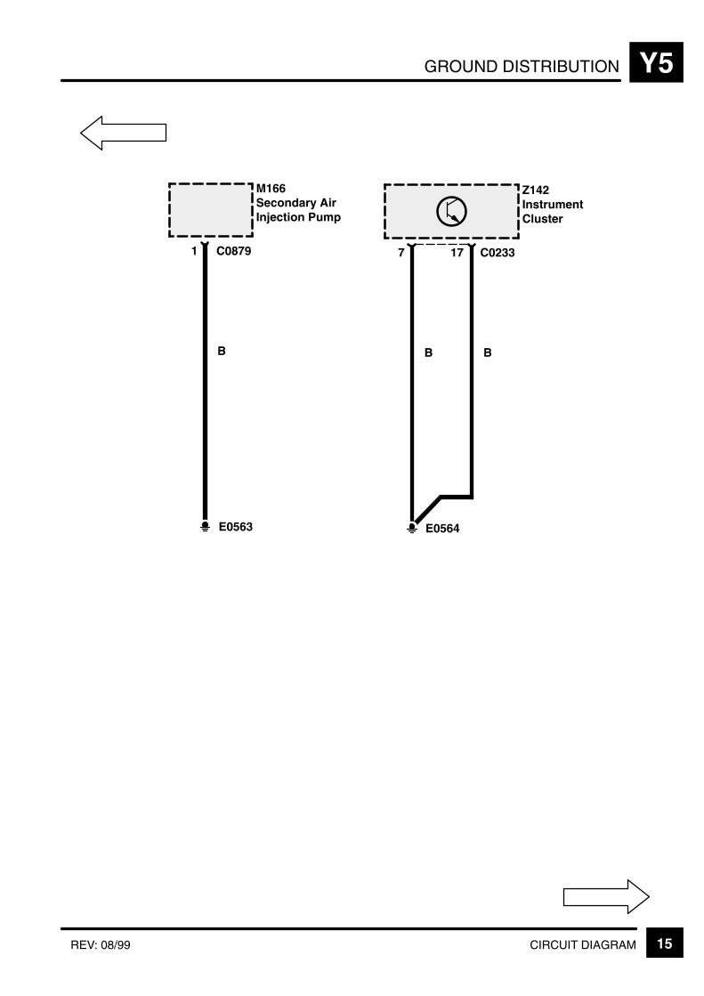
GROUND DISTRIBUTION Y5
15CIRCUIT DIAGRAMREV: 08/99
B
Z142InstrumentCluster
7 C023317
E0564
BB
M166Secondary AirInjection Pump
1 C0879
E0563
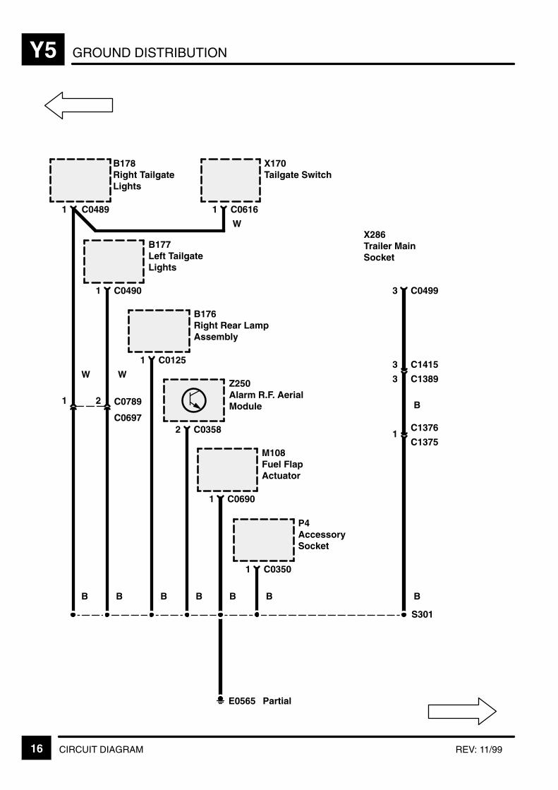
GROUND DISTRIBUTIONY5
16 CIRCUIT DIAGRAM REV: 11/99
W
B178Right TailgateLights
C04891
X170Tailgate Switch
C06161
W
B177Left TailgateLights
C04901
W
B176Right Rear LampAssembly
C01251
B
Z250Alarm R.F. AerialModule
C03582
B
M108Fuel FlapActuator
C06901
B
C04993
S301
E0565 Partial
X286Trailer MainSocket
C14153
C13893
C1376
C13751
B
B
B B
1 C07892
C0697
P4AccessorySocket
C03501
B
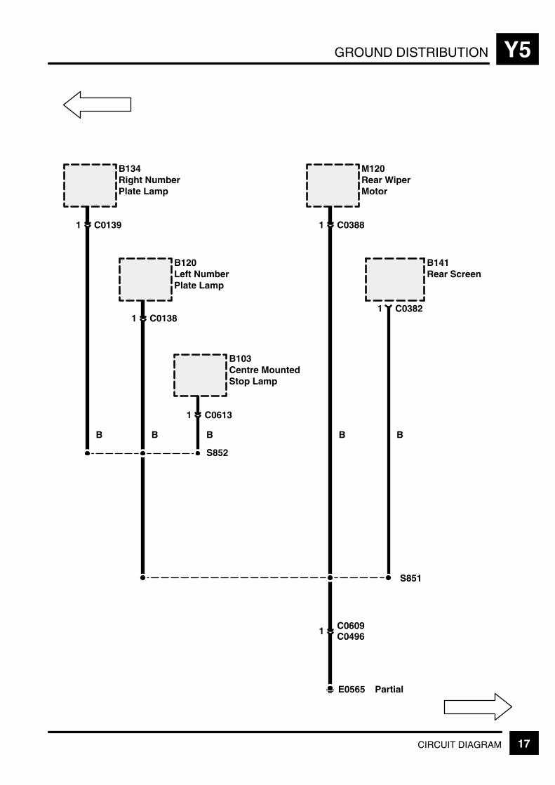
GROUND DISTRIBUTION Y5
17CIRCUIT DIAGRAM
B
B134Right NumberPlate Lamp
C01391
B
B141Rear Screen
C0382
B
B120Left NumberPlate Lamp
C01381
B
B103Centre MountedStop Lamp
C06131
B
M120Rear WiperMotor
C03881
C04961
S852
S851
E0565 Partial
1
C0609

GROUND DISTRIBUTIONY5
18 CIRCUIT DIAGRAM REV: 11/99
B
B172Sun–visorLamp 1
C07372
B
Z251Sunroof Anti–trap
C01263
B
B110ElectrochromicRear View Mirror
C06982
B
B107Front InteriorRoof Lamp
C03571
B
B173Sun–visorLamp 2
C07362
B
B179Right InteriorLights
C03563
E0807
S306
S304
Partial
X325Home LinkConnector
C09921
B
(MY 1999)
C0698 (MY 2000)(MY 1999)
10
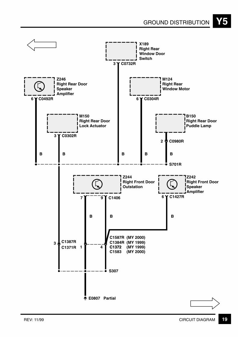
GROUND DISTRIBUTION Y5
19CIRCUIT DIAGRAMREV: 11/99
B
Z246Right Rear DoorSpeakerAmplifier
C0492R6
B
B150Right Rear DoorPuddle Lamp
C0980R2
S701R
B
M150Right Rear DoorLock Actuator
C0302R3
B
X189Right RearWindow DoorSwitch
C0732R3
B
M124Right RearWindow Motor
C0304R6
Z244Right Front DoorOutstation
7
Z242Right Front DoorSpeakerAmplifier
C1427R6C14069
B B
C13724C1384R
1C1371R3 C1387R
B
S307
E0807 Partial
C1587R(MY 1999)(MY 2000)
(MY 2000)C1372 (MY 1999)C1583
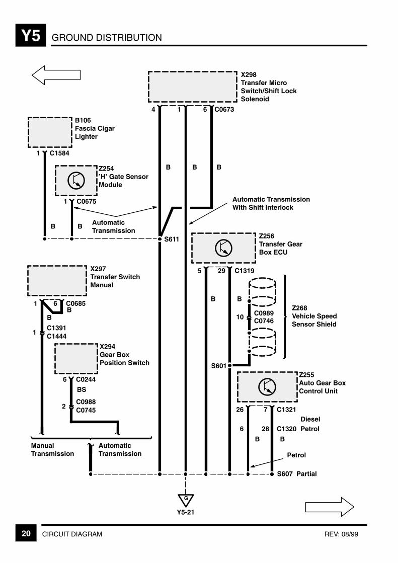
GROUND DISTRIBUTIONY5
20 CIRCUIT DIAGRAM REV: 08/99
B
B106Fascia CigarLighter
C15841
X294Gear BoxPosition Switch
C02446
B
Z254’H’ Gate SensorModule
C06751
X298Transfer MicroSwitch/Shift LockSolenoid
4 1
Z256Transfer GearBox ECU
5 C131929
Z268Vehicle SpeedSensor Shield
C098910 C0746
Z255Auto Gear BoxControl Unit
6
C13217
G
Y5-21
X297Transfer SwitchManual
1 C06856
C09882 C0745
BS
AutomaticTransmission
ManualTransmission
C13911 C1444
S611
S607 Partial
B B
Automatic TransmissionWith Shift Interlock
B B
S601
B B
Petrol
BB
AutomaticTransmission
C06736
B
C1320DieselPetrol28
26
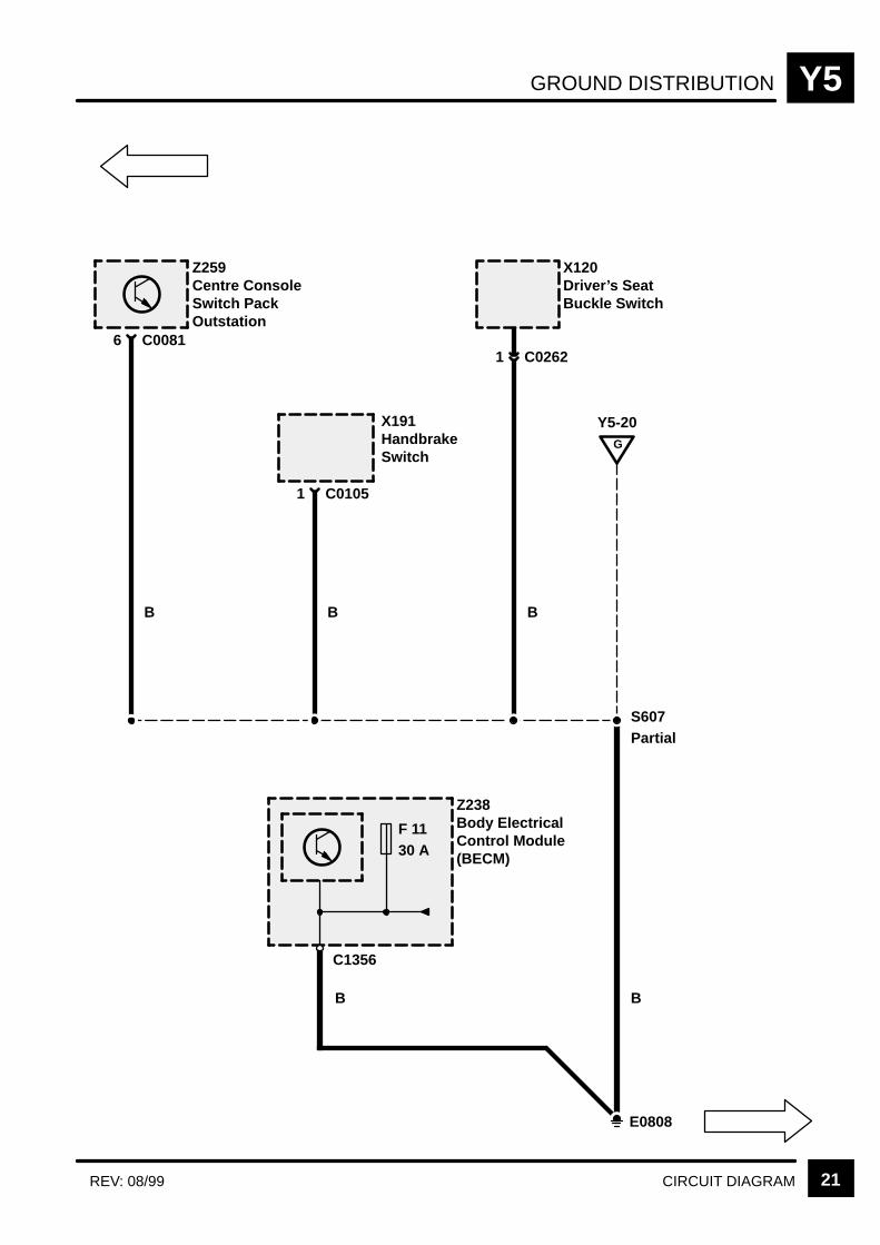
GROUND DISTRIBUTION Y5
21CIRCUIT DIAGRAMREV: 08/99
B
Z259Centre ConsoleSwitch PackOutstation
C00816
B
X191HandbrakeSwitch
C01051
B
X120Driver’s SeatBuckle Switch
C02621
E0808
Z238Body ElectricalControl Module(BECM)
F 1130 A
B
G
Y5-20
C1356
S607Partial
B

GROUND DISTRIBUTIONY5
22 CIRCUIT DIAGRAM REV: 08/99
Z176SubwooferAmplifier
C13823
S355
E0809 Partial
X172Trailer AuxiliarySocket
C13811
C1390
C1359
C13581
U
5
B
C1622C0834
C16216
U
B
B175Left Rear LampAssembly
C01211
B
Z205UltrasonicModule
C03592
B B
B180Left InteriorLights
C0355
S356
3
Dealer Fitment
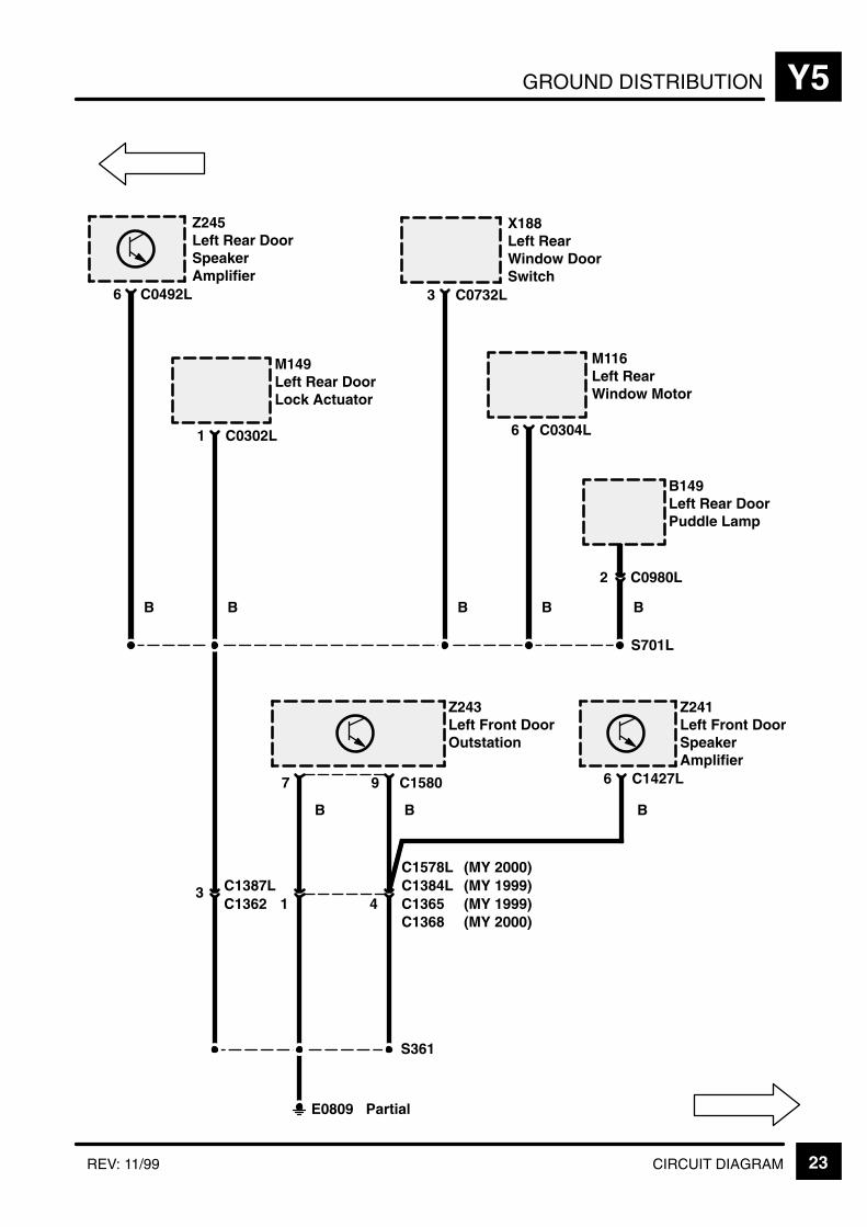
GROUND DISTRIBUTION Y5
23CIRCUIT DIAGRAMREV: 11/99
B
Z245Left Rear DoorSpeakerAmplifier
C0492L6
B
B149Left Rear DoorPuddle Lamp
C0980L2
S701L
B
M149Left Rear DoorLock Actuator
C0302L1
B
X188Left RearWindow DoorSwitch
C0732L3
B
M116Left RearWindow Motor
C0304L6
Z243Left Front DoorOutstation
7
Z241Left Front DoorSpeakerAmplifier
C1427L6C15809
B B
C13654C1384L
1C13623 C1387L
B
S361
E0809 Partial
C1578L(MY 1999)(MY 2000)
(MY 1999)C1368 (MY 2000)

GROUND DISTRIBUTIONY5
24 CIRCUIT DIAGRAM
R
Z285Capacitor Link 1
E0811
R
Z284Capacitor Link 3
S521
R
2
E0810
Z283Capacitor Link 2
M158Left BlowerMotor
M159Right BlowerMotor
E0910
Petrol
S530
Petrol
C00502 C0023
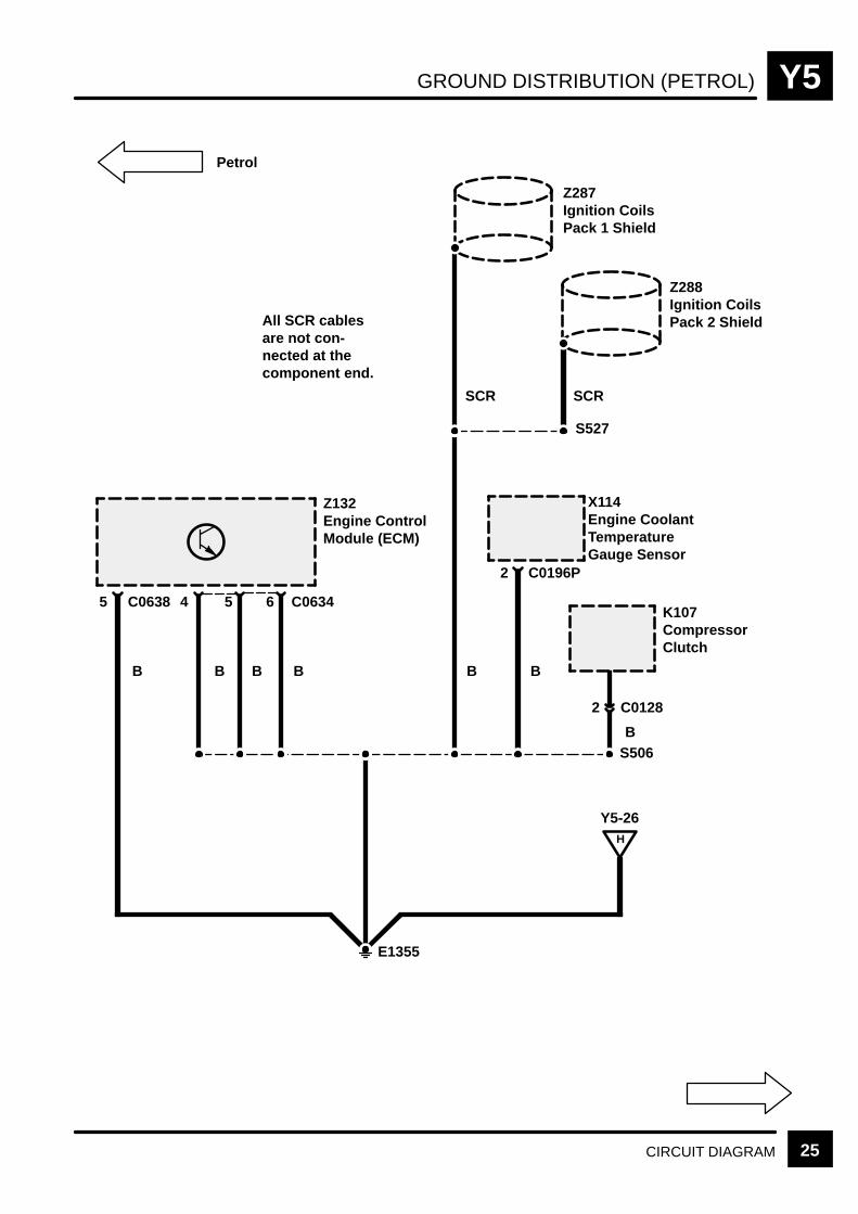
GROUND DISTRIBUTION (PETROL) Y5
25CIRCUIT DIAGRAM
Z132Engine ControlModule (ECM)
5
B
C06346
B
4
B
5
B
H
Y5-26
E1355
Petrol
X114Engine CoolantTemperatureGauge Sensor
C0196P2
B
K107CompressorClutch
B
Z287Ignition CoilsPack 1 Shield
Z288Ignition CoilsPack 2 ShieldAll SCR cables
are not con-nected at thecomponent end.
S527
SCR SCR
C0638
2 C0128
S506
B
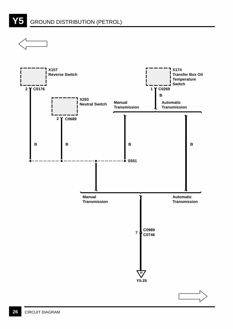
GROUND DISTRIBUTION (PETROL)Y5
26 CIRCUIT DIAGRAM
S551
X157Reverse Switch
C01762
B
X293Neutral Switch
C06892
B
X174Transfer Box OilTemperatureSwitch
C02691
B
ManualTransmission
AutomaticTransmission
B
ManualTransmission
AutomaticTransmission
C07467C0989
H
Y5-25
B
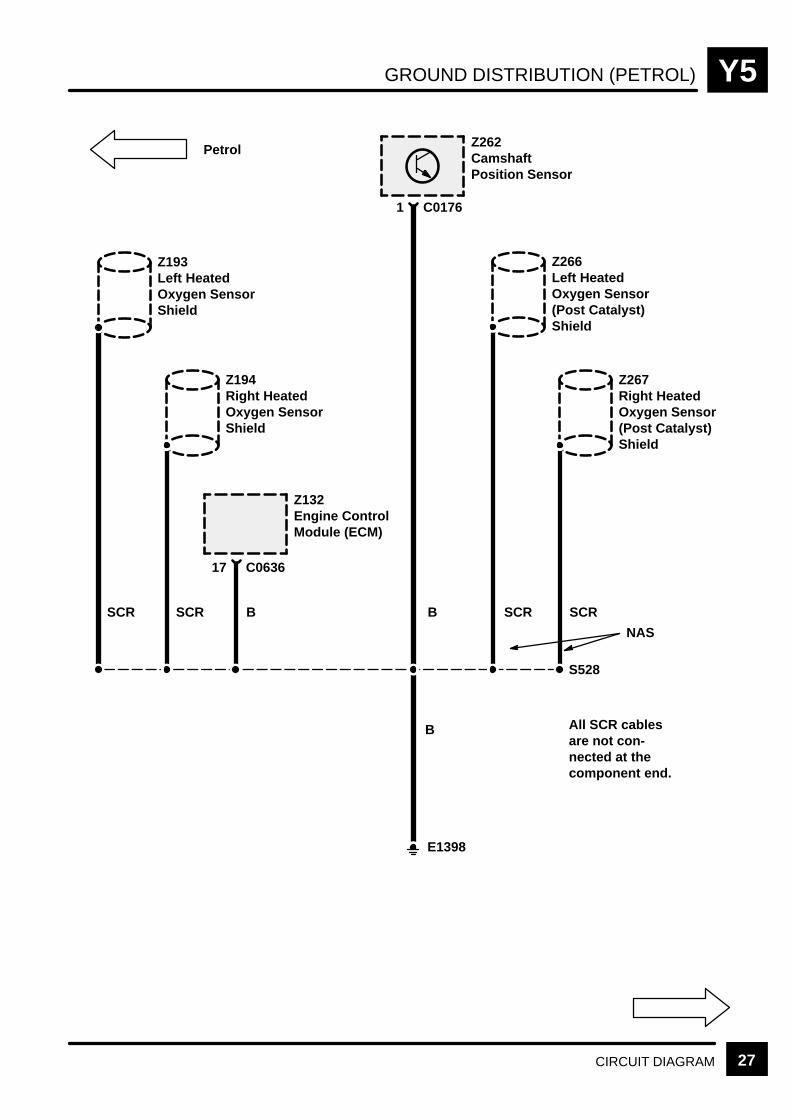
GROUND DISTRIBUTION (PETROL) Y5
27CIRCUIT DIAGRAM
Z193Left HeatedOxygen SensorShield
S528
Z194Right HeatedOxygen SensorShield
Z266Left HeatedOxygen Sensor(Post Catalyst)Shield
Z267Right HeatedOxygen Sensor(Post Catalyst)Shield
All SCR cablesare not con-nected at thecomponent end.
SCR SCR B B SCR SCR
NAS
Petrol Z262CamshaftPosition Sensor
C01761
Z132Engine ControlModule (ECM)
C063617
B
E1398
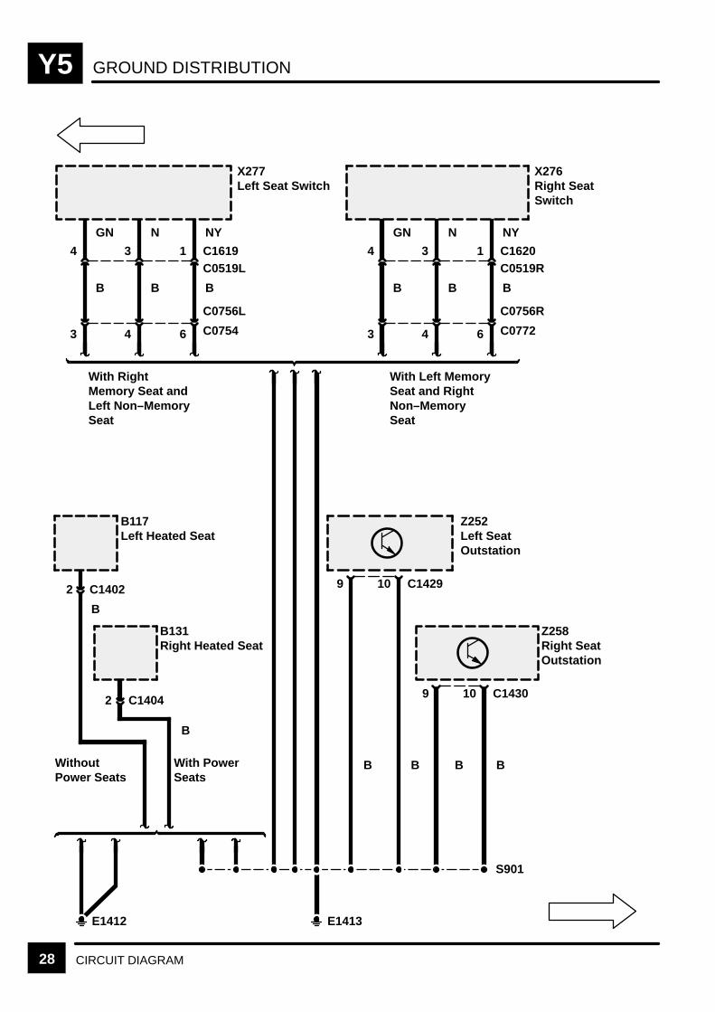
GROUND DISTRIBUTIONY5
28 CIRCUIT DIAGRAM
B
X276Right SeatSwitch
C0519R1 C1620
B
3
B
4
C07726
C0756R
43
B
X277Left Seat Switch
C0519L1 C1619
B
3
B
4
C07546
C0756L
43
With RightMemory Seat andLeft Non–MemorySeat
With Left MemorySeat and RightNon–MemorySeat
B
Z252Left SeatOutstation
9 C142910
B B
Z258Right SeatOutstation
9 C143010
B
B
B117Left Heated Seat
C14022
B
B131Right Heated Seat
C14042
WithoutPower Seats
With PowerSeats
E1412 E1413
S901
NYNGNNYNGN
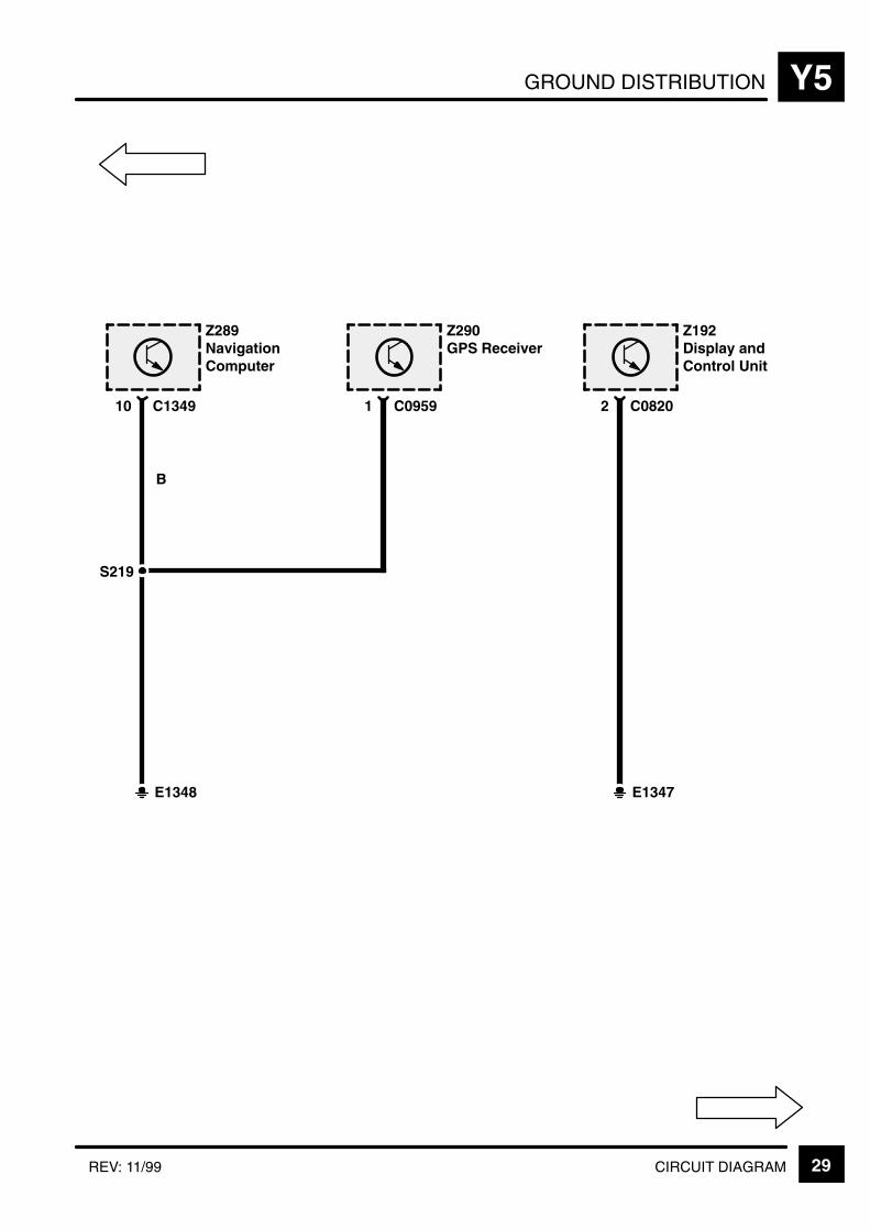
GROUND DISTRIBUTION Y5
29CIRCUIT DIAGRAMREV: 11/99
Z289NavigationComputer
C134910
Z290GPS Receiver
C09591
E1348
B
S219
Z192Display andControl Unit
C08202
E1347

GROUND DISTRIBUTIONY5
30 CIRCUIT DIAGRAM REV: 11/99
Z293DSP Amplifier
C049126
X176Air SuspensionDiagnosticConnector
C08345
B B
E1351
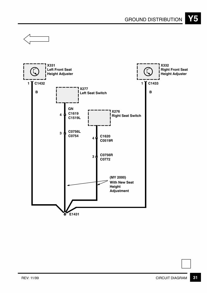
GROUND DISTRIBUTION Y5
31CIRCUIT DIAGRAMREV: 11/99
X331Left Front SeatHeight Adjuster
C14321
X332Right Front SeatHeight Adjuster
C14331
B BX277Left Seat Switch
GNX276Right Seat Switch
E1431
C1619C1519L
4
C0756LC0754
3C1620C0519R
4
C0756RC0772
3
With New SeatHeightAdjustment
(MY 2000)

KEY INFORMATIONi
!"
#$ % &'( ' )
*$ % &'( + %
,# % &'( ' )
% &'( ' )
-
*, !+
!
+ ' '
+ .) . . '
/+ +0 .
' /'+0
"% ) '
+ ) . % .
+ +- %
. )
(
.
!"
. ' % 1(
2 + " .
' ) '
2 +' 3 .
.' % '
2 .) % '
2 4 .' % '-
&+
+ )
+ /0 .
+ ' %

COMPONENT LOCATION TABLE Z4
1REV: 08/2002
For views of the connectors which are attached to the component refer to the connector table.
ÁÁÁÁÁÁÁÁÁÁÁÁÁÁÁÁÁÁÁÁÁÁ
A/C Aspirator (K219) . . . . . . . ÁÁÁÁÁÁÁÁÁÁÁÁÁÁÁÁÁÁÁÁÁÁÁÁÁÁÁÁÁÁÁÁÁÁÁÁÁÁ
centre of fascia . . . . . . . . . . . . . . . . . . . . . . . . . . . . . . . . . . . . . . . . ÁÁÁÁÁÁÁÁÁÁÁÁÁÁÁÁ
82
ÁÁÁÁÁÁÁÁÁÁÁÁÁÁÁÁÁÁÁÁÁÁ
A/C Dual Pressure Switch(X315) . . . . . . . . . . . . . . . . . . .
ÁÁÁÁÁÁÁÁÁÁÁÁÁÁÁÁÁÁÁÁÁÁÁÁÁÁÁÁÁÁÁÁÁÁÁÁÁÁbehind LH side of front bumper . . . . . . . . . . . . . . . . . . . . . . . . . . .
ÁÁÁÁÁÁÁÁÁÁÁÁÁÁÁÁ82ÁÁÁÁÁÁÁÁÁÁÁ
ÁÁÁÁÁÁÁÁÁÁÁABS Booster Unit (Z103) . . . ÁÁÁÁÁÁÁÁÁÁÁÁÁÁÁÁÁÁÁÁÁÁÁÁÁÁÁÁÁÁÁÁÁÁÁÁÁÁdriver’s side of engine compartment . . . . . . . . . . . . . . . . . . . . . .
ÁÁÁÁÁÁÁÁÁÁÁÁÁÁÁÁ70ÁÁÁÁÁÁÁÁÁÁÁ
ÁÁÁÁÁÁÁÁÁÁÁABS Hydraulic Pump (M102)ÁÁÁÁÁÁÁÁÁÁÁÁÁÁÁÁÁÁÁÁÁÁÁÁÁÁÁÁÁÁÁÁÁÁÁÁÁÁdriver’s side of engine compartment . . . . . . . . . . . . . . . . . . . . . .
ÁÁÁÁÁÁÁÁÁÁÁÁÁÁÁÁ70ÁÁÁÁÁÁÁÁÁÁÁ
ÁÁÁÁÁÁÁÁÁÁÁÁÁÁÁÁÁÁÁÁÁÁ
ABS Pressure Switch Unit(Z104) . . . . . . . . . . . . . . . . . . .
ÁÁÁÁÁÁÁÁÁÁÁÁÁÁÁÁÁÁÁÁÁÁÁÁÁÁÁÁÁÁÁÁÁÁÁÁÁÁÁÁÁÁÁÁÁÁÁÁÁÁÁÁÁÁÁÁÁ
driver’s side of engine compartment . . . . . . . . . . . . . . . . . . . . . .
ÁÁÁÁÁÁÁÁÁÁÁÁÁÁÁÁÁÁÁÁÁÁÁÁ
70ÁÁÁÁÁÁÁÁÁÁÁÁÁÁÁÁÁÁÁÁÁÁ
Accessory Socket (P4) . . . . . ÁÁÁÁÁÁÁÁÁÁÁÁÁÁÁÁÁÁÁÁÁÁÁÁÁÁÁÁÁÁÁÁÁÁÁÁÁÁ
RH rear of vehicle . . . . . . . . . . . . . . . . . . . . . . . . . . . . . . . . . . . . . . ÁÁÁÁÁÁÁÁÁÁÁÁÁÁÁÁ
86ÁÁÁÁÁÁÁÁÁÁÁÁÁÁÁÁÁÁÁÁÁÁ
Air Bag Diagnostic Connector(X226) . . . . . . . . . . . . . . . . . . .
ÁÁÁÁÁÁÁÁÁÁÁÁÁÁÁÁÁÁÁÁÁÁÁÁÁÁÁÁÁÁÁÁÁÁÁÁÁÁpassenger’s footwell . . . . . . . . . . . . . . . . . . . . . . . . . . . . . . . . . . . .
ÁÁÁÁÁÁÁÁÁÁÁÁÁÁÁÁ75ÁÁÁÁÁÁÁÁÁÁÁ
ÁÁÁÁÁÁÁÁÁÁÁÁÁÁÁÁÁÁÁÁÁÁ
Air Suspension Compressor(M140) . . . . . . . . . . . . . . . . . . .
ÁÁÁÁÁÁÁÁÁÁÁÁÁÁÁÁÁÁÁÁÁÁÁÁÁÁÁÁÁÁÁÁÁÁÁÁÁÁÁÁÁÁÁÁÁÁÁÁÁÁÁÁÁÁÁÁÁ
LH rear of engine compartment . . . . . . . . . . . . . . . . . . . . . . . . . .
ÁÁÁÁÁÁÁÁÁÁÁÁÁÁÁÁÁÁÁÁÁÁÁÁ
60ÁÁÁÁÁÁÁÁÁÁÁÁÁÁÁÁÁÁÁÁÁÁÁÁÁÁÁÁÁÁÁÁÁ
Air Suspension Delay TurnOff Timer (Z260) . . . . . . . . . .
ÁÁÁÁÁÁÁÁÁÁÁÁÁÁÁÁÁÁÁÁÁÁÁÁÁÁÁÁÁÁÁÁÁÁÁÁÁÁÁÁÁÁÁÁÁÁÁÁÁÁÁÁÁÁÁÁÁ
beneath LH front seat . . . . . . . . . . . . . . . . . . . . . . . . . . . . . . . . . . .
ÁÁÁÁÁÁÁÁÁÁÁÁÁÁÁÁÁÁÁÁÁÁÁÁ
60
ÁÁÁÁÁÁÁÁÁÁÁÁÁÁÁÁÁÁÁÁÁÁ
Air Suspension ECU (Z165) ÁÁÁÁÁÁÁÁÁÁÁÁÁÁÁÁÁÁÁÁÁÁÁÁÁÁÁÁÁÁÁÁÁÁÁÁÁÁ
beneath LH front seat . . . . . . . . . . . . . . . . . . . . . . . . . . . . . . . . . . . ÁÁÁÁÁÁÁÁÁÁÁÁÁÁÁÁ
60
ÁÁÁÁÁÁÁÁÁÁÁÁÁÁÁÁÁÁÁÁÁÁ
Air Suspension Inhibit Switch(X209) . . . . . . . . . . . . . . . . . . .
ÁÁÁÁÁÁÁÁÁÁÁÁÁÁÁÁÁÁÁÁÁÁÁÁÁÁÁÁÁÁÁÁÁÁÁÁÁÁcentre of fascia . . . . . . . . . . . . . . . . . . . . . . . . . . . . . . . . . . . . . . . .
ÁÁÁÁÁÁÁÁÁÁÁÁÁÁÁÁ60ÁÁÁÁÁÁÁÁÁÁÁ
ÁÁÁÁÁÁÁÁÁÁÁAir Valve Block (K163) . . . . .
ÁÁÁÁÁÁÁÁÁÁÁÁÁÁÁÁÁÁÁÁÁÁÁÁÁÁÁÁÁÁÁÁÁÁÁÁÁÁ
LH side of engine compartment . . . . . . . . . . . . . . . . . . . . . . . . . . ÁÁÁÁÁÁÁÁÁÁÁÁÁÁÁÁ
60ÁÁÁÁÁÁÁÁÁÁÁÁÁÁÁÁÁÁÁÁÁÁÁÁÁÁÁÁÁÁÁÁÁ
Alarm R.F. Antenna Module(Z250) . . . . . . . . . . . . . . . . . . .
ÁÁÁÁÁÁÁÁÁÁÁÁÁÁÁÁÁÁÁÁÁÁÁÁÁÁÁÁÁÁÁÁÁÁÁÁÁÁÁÁÁÁÁÁÁÁÁÁÁÁÁÁÁÁÁÁÁ
RH side of luggage compartment . . . . . . . . . . . . . . . . . . . . . . . . .
ÁÁÁÁÁÁÁÁÁÁÁÁÁÁÁÁÁÁÁÁÁÁÁÁ
86ÁÁÁÁÁÁÁÁÁÁÁÁÁÁÁÁÁÁÁÁÁÁ
Alarm Sounder (Z171) . . . . . ÁÁÁÁÁÁÁÁÁÁÁÁÁÁÁÁÁÁÁÁÁÁÁÁÁÁÁÁÁÁÁÁÁÁÁÁÁÁ
RH side of engine compartment . . . . . . . . . . . . . . . . . . . . . . . . . . ÁÁÁÁÁÁÁÁÁÁÁÁÁÁÁÁ
86ÁÁÁÁÁÁÁÁÁÁÁÁÁÁÁÁÁÁÁÁÁÁ
Ambient Air Sensor (K218) . ÁÁÁÁÁÁÁÁÁÁÁÁÁÁÁÁÁÁÁÁÁÁÁÁÁÁÁÁÁÁÁÁÁÁÁÁÁÁ
LH front of vehicle in front of condenser . . . . . . . . . . . . . . . . . . . ÁÁÁÁÁÁÁÁÁÁÁÁÁÁÁÁ
82
ÁÁÁÁÁÁÁÁÁÁÁÁÁÁÁÁÁÁÁÁÁÁ
Anti–Lock Brake System ECU(Z108) . . . . . . . . . . . . . . . . . . .
ÁÁÁÁÁÁÁÁÁÁÁÁÁÁÁÁÁÁÁÁÁÁÁÁÁÁÁÁÁÁÁÁÁÁÁÁÁÁbeneath fascia on passenger’s side of bulkhead . . . . . . . . . . . .
ÁÁÁÁÁÁÁÁÁÁÁÁÁÁÁÁ70ÁÁÁÁÁÁÁÁÁÁÁ
ÁÁÁÁÁÁÁÁÁÁÁÁÁÁÁÁÁÁÁÁÁÁ
Auto Gear Box Control Unit(Z255) . . . . . . . . . . . . . . . . . . .
ÁÁÁÁÁÁÁÁÁÁÁÁÁÁÁÁÁÁÁÁÁÁÁÁÁÁÁÁÁÁÁÁÁÁÁÁÁÁÁÁÁÁÁÁÁÁÁÁÁÁÁÁÁÁÁÁÁ
beneath LH front seat . . . . . . . . . . . . . . . . . . . . . . . . . . . . . . . . . . .
ÁÁÁÁÁÁÁÁÁÁÁÁÁÁÁÁÁÁÁÁÁÁÁÁ
44ÁÁÁÁÁÁÁÁÁÁÁÁÁÁÁÁÁÁÁÁÁÁÁÁÁÁÁÁÁÁÁÁÁ
Auto Gear Box Control Unit(Z255) . . . . . . . . . . . . . . . . . . .
ÁÁÁÁÁÁÁÁÁÁÁÁÁÁÁÁÁÁÁÁÁÁÁÁÁÁÁÁÁÁÁÁÁÁÁÁÁÁÁÁÁÁÁÁÁÁÁÁÁÁÁÁÁÁÁÁÁ
beneath LH front seat . . . . . . . . . . . . . . . . . . . . . . . . . . . . . . . . . . . ÁÁÁÁÁÁÁÁÁÁÁÁÁÁÁÁÁÁÁÁÁÁÁÁ
44
ÁÁÁÁÁÁÁÁÁÁÁÁÁÁÁÁÁÁÁÁÁÁ
Automatic Transmission OilTemperature Switch (X108) .
ÁÁÁÁÁÁÁÁÁÁÁÁÁÁÁÁÁÁÁÁÁÁÁÁÁÁÁÁÁÁÁÁÁÁÁÁÁÁLH front of engine compartment . . . . . . . . . . . . . . . . . . . . . . . . . .
ÁÁÁÁÁÁÁÁÁÁÁÁÁÁÁÁ44ÁÁÁÁÁÁÁÁÁÁÁ
ÁÁÁÁÁÁÁÁÁÁÁBattery (P104) . . . . . . . . . . . .
ÁÁÁÁÁÁÁÁÁÁÁÁÁÁÁÁÁÁÁÁÁÁÁÁÁÁÁÁÁÁÁÁÁÁÁÁÁÁ
RH front of engine compartment . . . . . . . . . . . . . . . . . . . . . . . . . . ÁÁÁÁÁÁÁÁÁÁÁÁÁÁÁÁ
86ÁÁÁÁÁÁÁÁÁÁÁÁÁÁÁÁÁÁÁÁÁÁÁÁÁÁÁÁÁÁÁÁÁ
Battery Backed Up AlarmSounder (Z272) . . . . . . . . . . .
ÁÁÁÁÁÁÁÁÁÁÁÁÁÁÁÁÁÁÁÁÁÁÁÁÁÁÁÁÁÁÁÁÁÁÁÁÁÁÁÁÁÁÁÁÁÁÁÁÁÁÁÁÁÁÁÁÁ
RH side of engine compartment . . . . . . . . . . . . . . . . . . . . . . . . . .
ÁÁÁÁÁÁÁÁÁÁÁÁÁÁÁÁÁÁÁÁÁÁÁÁ
86ÁÁÁÁÁÁÁÁÁÁÁÁÁÁÁÁÁÁÁÁÁÁ
Body Electrical ControlModule (BECM) (Z238) . . . .
ÁÁÁÁÁÁÁÁÁÁÁÁÁÁÁÁÁÁÁÁÁÁÁÁÁÁÁÁÁÁÁÁÁÁÁÁÁÁbeneath RH front seat . . . . . . . . . . . . . . . . . . . . . . . . . . . . . . . . . . .
ÁÁÁÁÁÁÁÁÁÁÁÁÁÁÁÁ76ÁÁÁÁÁÁÁÁÁÁÁ
ÁÁÁÁÁÁÁÁÁÁÁBonnet Switch (X110) . . . . . . ÁÁÁÁÁÁÁÁÁÁÁÁÁÁÁÁÁÁÁÁÁÁÁÁÁÁÁÁÁÁÁÁÁÁÁÁÁÁRH front of engine compartment near Right Horn . . . . . . . . . . .
ÁÁÁÁÁÁÁÁÁÁÁÁÁÁÁÁ86ÁÁÁÁÁÁÁÁÁÁÁ
ÁÁÁÁÁÁÁÁÁÁÁÁÁÁÁÁÁÁÁÁÁÁ
Boost Pressure Sensor(X253) . . . . . . . . . . . . . . . . . . .
ÁÁÁÁÁÁÁÁÁÁÁÁÁÁÁÁÁÁÁÁÁÁÁÁÁÁÁÁÁÁÁÁÁÁÁÁÁÁÁÁÁÁÁÁÁÁÁÁÁÁÁÁÁÁÁÁÁ
LH rear of engine compartment . . . . . . . . . . . . . . . . . . . . . . . . . .
ÁÁÁÁÁÁÁÁÁÁÁÁÁÁÁÁÁÁÁÁÁÁÁÁ
19ÁÁÁÁÁÁÁÁÁÁÁÁÁÁÁÁÁÁÁÁÁÁÁÁÁÁÁÁÁÁÁÁÁ
Brake Fluid Level Switch(X111) . . . . . . . . . . . . . . . . . . .
ÁÁÁÁÁÁÁÁÁÁÁÁÁÁÁÁÁÁÁÁÁÁÁÁÁÁÁÁÁÁÁÁÁÁÁÁÁÁÁÁÁÁÁÁÁÁÁÁÁÁÁÁÁÁÁÁÁ
driver’s side of engine compartment . . . . . . . . . . . . . . . . . . . . . . ÁÁÁÁÁÁÁÁÁÁÁÁÁÁÁÁÁÁÁÁÁÁÁÁ
70
ÁÁÁÁÁÁÁÁÁÁÁÁÁÁÁÁÁÁÁÁÁÁ
Brake Switch Vent Valve(X112) . . . . . . . . . . . . . . . . . . .
ÁÁÁÁÁÁÁÁÁÁÁÁÁÁÁÁÁÁÁÁÁÁÁÁÁÁÁÁÁÁÁÁÁÁÁÁÁÁbehind driver’s side of fascia on brake pedal support . . . . . . . .
ÁÁÁÁÁÁÁÁÁÁÁÁÁÁÁÁ70ÁÁÁÁÁÁÁÁÁÁÁ
ÁÁÁÁÁÁÁÁÁÁÁÁÁÁÁÁÁÁÁÁÁÁ
Camshaft Position Sensor(Z262) . . . . . . . . . . . . . . . . . . .
ÁÁÁÁÁÁÁÁÁÁÁÁÁÁÁÁÁÁÁÁÁÁÁÁÁÁÁÁÁÁÁÁÁÁÁÁÁÁÁÁÁÁÁÁÁÁÁÁÁÁÁÁÁÁÁÁÁ
LH front of engine . . . . . . . . . . . . . . . . . . . . . . . . . . . . . . . . . . . . . .
ÁÁÁÁÁÁÁÁÁÁÁÁÁÁÁÁÁÁÁÁÁÁÁÁ
19ÁÁÁÁÁÁÁÁÁÁÁÁÁÁÁÁÁÁÁÁÁÁ
Capacitor Link 1 (Z285) . . . . ÁÁÁÁÁÁÁÁÁÁÁÁÁÁÁÁÁÁÁÁÁÁÁÁÁÁÁÁÁÁÁÁÁÁÁÁÁÁ
LH side of engine . . . . . . . . . . . . . . . . . . . . . . . . . . . . . . . . . . . . . . . ÁÁÁÁÁÁÁÁÁÁÁÁÁÁÁÁ
12ÁÁÁÁÁÁÁÁÁÁÁÁÁÁÁÁÁÁÁÁÁÁ
Capacitor Link 2 (Z283) . . . . ÁÁÁÁÁÁÁÁÁÁÁÁÁÁÁÁÁÁÁÁÁÁÁÁÁÁÁÁÁÁÁÁÁÁÁÁÁÁ
LH side of engine . . . . . . . . . . . . . . . . . . . . . . . . . . . . . . . . . . . . . . . ÁÁÁÁÁÁÁÁÁÁÁÁÁÁÁÁ
12
ÁÁÁÁÁÁÁÁÁÁÁÁÁÁÁÁÁÁÁÁÁÁ
Capacitor Link 3 (Z284) . . . . ÁÁÁÁÁÁÁÁÁÁÁÁÁÁÁÁÁÁÁÁÁÁÁÁÁÁÁÁÁÁÁÁÁÁÁÁÁÁ
LH rear corner of engine compartment . . . . . . . . . . . . . . . . . . . . ÁÁÁÁÁÁÁÁÁÁÁÁÁÁÁÁ
12
ÁÁÁÁÁÁÁÁÁÁÁÁÁÁÁÁÁÁÁÁÁÁ
CD Changer (Z114) . . . . . . . . ÁÁÁÁÁÁÁÁÁÁÁÁÁÁÁÁÁÁÁÁÁÁÁÁÁÁÁÁÁÁÁÁÁÁÁÁÁÁ
LH rear of luggage compartment . . . . . . . . . . . . . . . . . . . . . . . . . ÁÁÁÁÁÁÁÁÁÁÁÁÁÁÁÁ
86
ÁÁÁÁÁÁÁÁÁÁÁÁÁÁÁÁÁÁÁÁÁÁ
Centre Console Switch PackOutstation (Z259) . . . . . . . . .
ÁÁÁÁÁÁÁÁÁÁÁÁÁÁÁÁÁÁÁÁÁÁÁÁÁÁÁÁÁÁÁÁÁÁÁÁÁÁin centre console . . . . . . . . . . . . . . . . . . . . . . . . . . . . . . . . . . . . . . .
ÁÁÁÁÁÁÁÁÁÁÁÁÁÁÁÁ86

COMPONENT LOCATION TABLEZ4
2 REV: 08/2002
ÁÁÁÁÁÁÁÁÁÁÁÁÁÁÁÁÁÁÁÁ
Centre Mounted Stop Lamp(B103) . . . . . . . . . . . . . . . . . . .
ÁÁÁÁÁÁÁÁÁÁÁÁÁÁÁÁÁÁÁÁÁÁÁÁÁÁÁÁÁÁÁÁÁÁÁÁÁÁÁÁlower centre of rear screen . . . . . . . . . . . . . . . . . . . . . . . . . . . . . .
ÁÁÁÁÁÁÁÁÁÁÁÁÁÁ86ÁÁÁÁÁÁÁÁÁÁ
ÁÁÁÁÁÁÁÁÁÁClock (Z117) . . . . . . . . . . . . . . ÁÁÁÁÁÁÁÁÁÁÁÁÁÁÁÁÁÁÁÁÁÁÁÁÁÁÁÁÁÁÁÁÁÁÁÁÁÁÁÁcentre of fascia . . . . . . . . . . . . . . . . . . . . . . . . . . . . . . . . . . . . . . . .
ÁÁÁÁÁÁÁÁÁÁÁÁÁÁ88ÁÁÁÁÁÁÁÁÁÁ
ÁÁÁÁÁÁÁÁÁÁÁÁÁÁÁÁÁÁÁÁ
Clutch Pedal Position Switch(X200) (Diesel) . . . . . . . . . . . .
ÁÁÁÁÁÁÁÁÁÁÁÁÁÁÁÁÁÁÁÁÁÁÁÁÁÁÁÁÁÁÁÁÁÁÁÁÁÁÁÁÁÁÁÁÁÁÁÁÁÁÁÁÁÁÁÁÁÁÁÁ
behind driver’s side of fascia (lower dash panel removed) . . . .
ÁÁÁÁÁÁÁÁÁÁÁÁÁÁÁÁÁÁÁÁÁ
19ÁÁÁÁÁÁÁÁÁÁÁÁÁÁÁÁÁÁÁÁÁÁÁÁÁÁÁÁÁÁ
Clutch Pedal Position Switch(X200) (Petrol) . . . . . . . . . . . .
ÁÁÁÁÁÁÁÁÁÁÁÁÁÁÁÁÁÁÁÁÁÁÁÁÁÁÁÁÁÁÁÁÁÁÁÁÁÁÁÁÁÁÁÁÁÁÁÁÁÁÁÁÁÁÁÁÁÁÁÁ
behind driver’s side of fascia (lower dash panel removed) . . . . ÁÁÁÁÁÁÁÁÁÁÁÁÁÁÁÁÁÁÁÁÁ
19
ÁÁÁÁÁÁÁÁÁÁÁÁÁÁÁÁÁÁÁÁ
Compressor Clutch (K107)(Diesel) . . . . . . . . . . . . . . . . . .
ÁÁÁÁÁÁÁÁÁÁÁÁÁÁÁÁÁÁÁÁÁÁÁÁÁÁÁÁÁÁÁÁÁÁÁÁÁÁÁÁ
RH front of engine . . . . . . . . . . . . . . . . . . . . . . . . . . . . . . . . . . . . . . ÁÁÁÁÁÁÁÁÁÁÁÁÁÁ
82ÁÁÁÁÁÁÁÁÁÁÁÁÁÁÁÁÁÁÁÁÁÁÁÁÁÁÁÁÁÁ
Compressor Clutch (K107)(Petrol) . . . . . . . . . . . . . . . . . .
ÁÁÁÁÁÁÁÁÁÁÁÁÁÁÁÁÁÁÁÁÁÁÁÁÁÁÁÁÁÁÁÁÁÁÁÁÁÁÁÁÁÁÁÁÁÁÁÁÁÁÁÁÁÁÁÁÁÁÁÁ
LH front of engine . . . . . . . . . . . . . . . . . . . . . . . . . . . . . . . . . . . . . .
ÁÁÁÁÁÁÁÁÁÁÁÁÁÁÁÁÁÁÁÁÁ
82ÁÁÁÁÁÁÁÁÁÁÁÁÁÁÁÁÁÁÁÁ
Cooling Fan Motor (M167) . . ÁÁÁÁÁÁÁÁÁÁÁÁÁÁÁÁÁÁÁÁÁÁÁÁÁÁÁÁÁÁÁÁÁÁÁÁÁÁÁÁ
LH front corner of engine compartment . . . . . . . . . . . . . . . . . . . . ÁÁÁÁÁÁÁÁÁÁÁÁÁÁ
44
ÁÁÁÁÁÁÁÁÁÁÁÁÁÁÁÁÁÁÁÁ
Cooling Fan Switch (X335) . ÁÁÁÁÁÁÁÁÁÁÁÁÁÁÁÁÁÁÁÁÁÁÁÁÁÁÁÁÁÁÁÁÁÁÁÁÁÁÁÁ
LH front corner of engine compartment . . . . . . . . . . . . . . . . . . . . ÁÁÁÁÁÁÁÁÁÁÁÁÁÁ
44
ÁÁÁÁÁÁÁÁÁÁÁÁÁÁÁÁÁÁÁÁ
Crankshaft Position Sensor(X250) . . . . . . . . . . . . . . . . . . .
ÁÁÁÁÁÁÁÁÁÁÁÁÁÁÁÁÁÁÁÁÁÁÁÁÁÁÁÁÁÁÁÁÁÁÁÁÁÁÁÁLH rear of engine . . . . . . . . . . . . . . . . . . . . . . . . . . . . . . . . . . . . . . .
ÁÁÁÁÁÁÁÁÁÁÁÁÁÁ19ÁÁÁÁÁÁÁÁÁÁ
ÁÁÁÁÁÁÁÁÁÁÁÁÁÁÁÁÁÁÁÁÁÁÁÁÁÁÁÁÁÁ
Cruise ControlConverter/Inverter Module(Z249) (Diesel) . . . . . . . . . . . .
ÁÁÁÁÁÁÁÁÁÁÁÁÁÁÁÁÁÁÁÁÁÁÁÁÁÁÁÁÁÁÁÁÁÁÁÁÁÁÁÁÁÁÁÁÁÁÁÁÁÁÁÁÁÁÁÁÁÁÁÁÁÁÁÁÁÁÁÁÁÁÁÁÁÁÁÁÁÁÁÁ
behind RH side of fascia right of steering column . . . . . . . . . . .
ÁÁÁÁÁÁÁÁÁÁÁÁÁÁÁÁÁÁÁÁÁÁÁÁÁÁÁÁ
19
ÁÁÁÁÁÁÁÁÁÁÁÁÁÁÁÁÁÁÁÁÁÁÁÁÁÁÁÁÁÁ
Cruise ControlConverter/Inverter Module(Z249) (Petrol) . . . . . . . . . . . .
ÁÁÁÁÁÁÁÁÁÁÁÁÁÁÁÁÁÁÁÁÁÁÁÁÁÁÁÁÁÁÁÁÁÁÁÁÁÁÁÁÁÁÁÁÁÁÁÁÁÁÁÁÁÁÁÁÁÁÁÁ
behind RH side of fascia right of steering column . . . . . . . . . . .
ÁÁÁÁÁÁÁÁÁÁÁÁÁÁÁÁÁÁÁÁÁ
19ÁÁÁÁÁÁÁÁÁÁÁÁÁÁÁÁÁÁÁÁ
Cruise Control ECU (Z121) . ÁÁÁÁÁÁÁÁÁÁÁÁÁÁÁÁÁÁÁÁÁÁÁÁÁÁÁÁÁÁÁÁÁÁÁÁÁÁÁÁ
behind RH side of fascia right of steering column . . . . . . . . . . . ÁÁÁÁÁÁÁÁÁÁÁÁÁÁ
19ÁÁÁÁÁÁÁÁÁÁÁÁÁÁÁÁÁÁÁÁ
Cruise Control Switch (X115)ÁÁÁÁÁÁÁÁÁÁÁÁÁÁÁÁÁÁÁÁÁÁÁÁÁÁÁÁÁÁÁÁÁÁÁÁÁÁÁÁ
centre of fascia . . . . . . . . . . . . . . . . . . . . . . . . . . . . . . . . . . . . . . . . ÁÁÁÁÁÁÁÁÁÁÁÁÁÁ
19ÁÁÁÁÁÁÁÁÁÁÁÁÁÁÁÁÁÁÁÁÁÁÁÁÁÁÁÁÁÁ
Cruise Control Vacuum Pump(M103) . . . . . . . . . . . . . . . . . . .
ÁÁÁÁÁÁÁÁÁÁÁÁÁÁÁÁÁÁÁÁÁÁÁÁÁÁÁÁÁÁÁÁÁÁÁÁÁÁÁÁÁÁÁÁÁÁÁÁÁÁÁÁÁÁÁÁÁÁÁÁ
LH rear corner of engine compartment . . . . . . . . . . . . . . . . . . . . ÁÁÁÁÁÁÁÁÁÁÁÁÁÁÁÁÁÁÁÁÁ
19
ÁÁÁÁÁÁÁÁÁÁÁÁÁÁÁÁÁÁÁÁ
Data Link Connectors (X318)ÁÁÁÁÁÁÁÁÁÁÁÁÁÁÁÁÁÁÁÁÁÁÁÁÁÁÁÁÁÁÁÁÁÁÁÁÁÁÁÁ
passenger’s footwell . . . . . . . . . . . . . . . . . . . . . . . . . . . . . . . . . . . . ÁÁÁÁÁÁÁÁÁÁÁÁÁÁ
86
ÁÁÁÁÁÁÁÁÁÁDiaphragm Valve (K220) . . . ÁÁÁÁÁÁÁÁÁÁÁÁÁÁÁÁÁÁÁÁLH side of engine compartment . . . . . . . . . . . . . . . . . . . . . . . . . . ÁÁÁÁÁÁÁ60ÁÁÁÁÁÁÁÁÁÁÁÁÁÁÁÁÁÁÁÁDiaphragm Valve (X302) . . .
ÁÁÁÁÁÁÁÁÁÁÁÁÁÁÁÁÁÁÁÁÁÁÁÁÁÁÁÁÁÁÁÁÁÁÁÁÁÁÁÁLH side of engine compartment . . . . . . . . . . . . . . . . . . . . . . . . . .
ÁÁÁÁÁÁÁÁÁÁÁÁÁÁ60ÁÁÁÁÁÁÁÁÁÁ
ÁÁÁÁÁÁÁÁÁÁÁÁÁÁÁÁÁÁÁÁ
Differential Lock Switch(X238) . . . . . . . . . . . . . . . . . . .
ÁÁÁÁÁÁÁÁÁÁÁÁÁÁÁÁÁÁÁÁÁÁÁÁÁÁÁÁÁÁÁÁÁÁÁÁÁÁÁÁÁÁÁÁÁÁÁÁÁÁÁÁÁÁÁÁÁÁÁÁ
LH rear corner of engine compartment . . . . . . . . . . . . . . . . . . . .
ÁÁÁÁÁÁÁÁÁÁÁÁÁÁÁÁÁÁÁÁÁ
86ÁÁÁÁÁÁÁÁÁÁÁÁÁÁÁÁÁÁÁÁ
Direction Indicator (X273) . . ÁÁÁÁÁÁÁÁÁÁÁÁÁÁÁÁÁÁÁÁÁÁÁÁÁÁÁÁÁÁÁÁÁÁÁÁÁÁÁÁ
left of steering column . . . . . . . . . . . . . . . . . . . . . . . . . . . . . . . . . . . ÁÁÁÁÁÁÁÁÁÁÁÁÁÁ
86ÁÁÁÁÁÁÁÁÁÁÁÁÁÁÁÁÁÁÁÁÁÁÁÁÁÁÁÁÁÁ
Display and Control Unit(Z291) . . . . . . . . . . . . . . . . . . .
ÁÁÁÁÁÁÁÁÁÁÁÁÁÁÁÁÁÁÁÁÁÁÁÁÁÁÁÁÁÁÁÁÁÁÁÁÁÁÁÁÁÁÁÁÁÁÁÁÁÁÁÁÁÁÁÁÁÁÁÁ
centre of fascia . . . . . . . . . . . . . . . . . . . . . . . . . . . . . . . . . . . . . . . . ÁÁÁÁÁÁÁÁÁÁÁÁÁÁÁÁÁÁÁÁÁ
87
ÁÁÁÁÁÁÁÁÁÁÁÁÁÁÁÁÁÁÁÁ
Distribution Motor (M165) . . . ÁÁÁÁÁÁÁÁÁÁÁÁÁÁÁÁÁÁÁÁÁÁÁÁÁÁÁÁÁÁÁÁÁÁÁÁÁÁÁÁ
beneath centre of fascia . . . . . . . . . . . . . . . . . . . . . . . . . . . . . . . . . ÁÁÁÁÁÁÁÁÁÁÁÁÁÁ
82
ÁÁÁÁÁÁÁÁÁÁÁÁÁÁÁÁÁÁÁÁ
Driver’s Air Bag (K177) . . . . . ÁÁÁÁÁÁÁÁÁÁÁÁÁÁÁÁÁÁÁÁÁÁÁÁÁÁÁÁÁÁÁÁÁÁÁÁÁÁÁÁ
driver’s side on steering wheel . . . . . . . . . . . . . . . . . . . . . . . . . . . ÁÁÁÁÁÁÁÁÁÁÁÁÁÁ
75
ÁÁÁÁÁÁÁÁÁÁÁÁÁÁÁÁÁÁÁÁ
Driver’s Seat Buckle Switch(X120) . . . . . . . . . . . . . . . . . . .
ÁÁÁÁÁÁÁÁÁÁÁÁÁÁÁÁÁÁÁÁÁÁÁÁÁÁÁÁÁÁÁÁÁÁÁÁÁÁÁÁ
inside driver’s seat belt buckle assembly . . . . . . . . . . . . . . . . . . . ÁÁÁÁÁÁÁÁÁÁÁÁÁÁ
86ÁÁÁÁÁÁÁÁÁÁÁÁÁÁÁÁÁÁÁÁ
DSP Amplifier (Z293) . . . . . . ÁÁÁÁÁÁÁÁÁÁÁÁÁÁÁÁÁÁÁÁÁÁÁÁÁÁÁÁÁÁÁÁÁÁÁÁÁÁÁÁ
LH side of luggage compartment . . . . . . . . . . . . . . . . . . . . . . . . . ÁÁÁÁÁÁÁÁÁÁÁÁÁÁ
86ÁÁÁÁÁÁÁÁÁÁÁÁÁÁÁÁÁÁÁÁ
EGR Control Solenoid (K171)ÁÁÁÁÁÁÁÁÁÁÁÁÁÁÁÁÁÁÁÁÁÁÁÁÁÁÁÁÁÁÁÁÁÁÁÁÁÁÁÁ
front LH wing in beneath engine compartment fuse box . . . . . ÁÁÁÁÁÁÁÁÁÁÁÁÁÁ
86ÁÁÁÁÁÁÁÁÁÁÁÁÁÁÁÁÁÁÁÁÁÁÁÁÁÁÁÁÁÁ
Electrochromatic Rear ViewMirror (B110) . . . . . . . . . . . . .
ÁÁÁÁÁÁÁÁÁÁÁÁÁÁÁÁÁÁÁÁÁÁÁÁÁÁÁÁÁÁÁÁÁÁÁÁÁÁÁÁÁÁÁÁÁÁÁÁÁÁÁÁÁÁÁÁÁÁÁÁ
top centre of front screen . . . . . . . . . . . . . . . . . . . . . . . . . . . . . . . .
ÁÁÁÁÁÁÁÁÁÁÁÁÁÁÁÁÁÁÁÁÁ
76
ÁÁÁÁÁÁÁÁÁÁÁÁÁÁÁÁÁÁÁÁ
Engine Compartment FuseBox (P125a) . . . . . . . . . . . . . .
ÁÁÁÁÁÁÁÁÁÁÁÁÁÁÁÁÁÁÁÁÁÁÁÁÁÁÁÁÁÁÁÁÁÁÁÁÁÁÁÁRH side of engine compartment . . . . . . . . . . . . . . . . . . . . . . . . . .
ÁÁÁÁÁÁÁÁÁÁÁÁÁÁ86ÁÁÁÁÁÁÁÁÁÁ
ÁÁÁÁÁÁÁÁÁÁÁÁÁÁÁÁÁÁÁÁ
Engine Control Module (ECM)(Z132) (Diesel) . . . . . . . . . . . .
ÁÁÁÁÁÁÁÁÁÁÁÁÁÁÁÁÁÁÁÁÁÁÁÁÁÁÁÁÁÁÁÁÁÁÁÁÁÁÁÁÁÁÁÁÁÁÁÁÁÁÁÁÁÁÁÁÁÁÁÁ
RH side of engine compartment behind battery . . . . . . . . . . . . .
ÁÁÁÁÁÁÁÁÁÁÁÁÁÁÁÁÁÁÁÁÁ
19ÁÁÁÁÁÁÁÁÁÁÁÁÁÁÁÁÁÁÁÁÁÁÁÁÁÁÁÁÁÁ
Engine Control Module (ECM)(Z132) (Petrol) . . . . . . . . . . . .
ÁÁÁÁÁÁÁÁÁÁÁÁÁÁÁÁÁÁÁÁÁÁÁÁÁÁÁÁÁÁÁÁÁÁÁÁÁÁÁÁÁÁÁÁÁÁÁÁÁÁÁÁÁÁÁÁÁÁÁÁ
RH side of engine compartment . . . . . . . . . . . . . . . . . . . . . . . . . . ÁÁÁÁÁÁÁÁÁÁÁÁÁÁÁÁÁÁÁÁÁ
19
ÁÁÁÁÁÁÁÁÁÁÁÁÁÁÁÁÁÁÁÁÁÁÁÁÁÁÁÁÁÁ
Engine Coolant TemperatureGauge Sensor (X114)(Diesel) . . . . . . . . . . . . . . . . . .
ÁÁÁÁÁÁÁÁÁÁÁÁÁÁÁÁÁÁÁÁÁÁÁÁÁÁÁÁÁÁÁÁÁÁÁÁÁÁÁÁÁÁÁÁÁÁÁÁÁÁÁÁÁÁÁÁÁÁÁÁ
LH side of engine . . . . . . . . . . . . . . . . . . . . . . . . . . . . . . . . . . . . . . .
ÁÁÁÁÁÁÁÁÁÁÁÁÁÁÁÁÁÁÁÁÁ
88ÁÁÁÁÁÁÁÁÁÁÁÁÁÁÁÁÁÁÁÁÁÁÁÁÁÁÁÁÁÁ
Engine Coolant TemperatureSensor (X126) (Diesel) . . . . .
ÁÁÁÁÁÁÁÁÁÁÁÁÁÁÁÁÁÁÁÁÁÁÁÁÁÁÁÁÁÁÁÁÁÁÁÁÁÁÁÁÁÁÁÁÁÁÁÁÁÁÁÁÁÁÁÁÁÁÁÁ
LH side of engine . . . . . . . . . . . . . . . . . . . . . . . . . . . . . . . . . . . . . . . ÁÁÁÁÁÁÁÁÁÁÁÁÁÁÁÁÁÁÁÁÁ
19
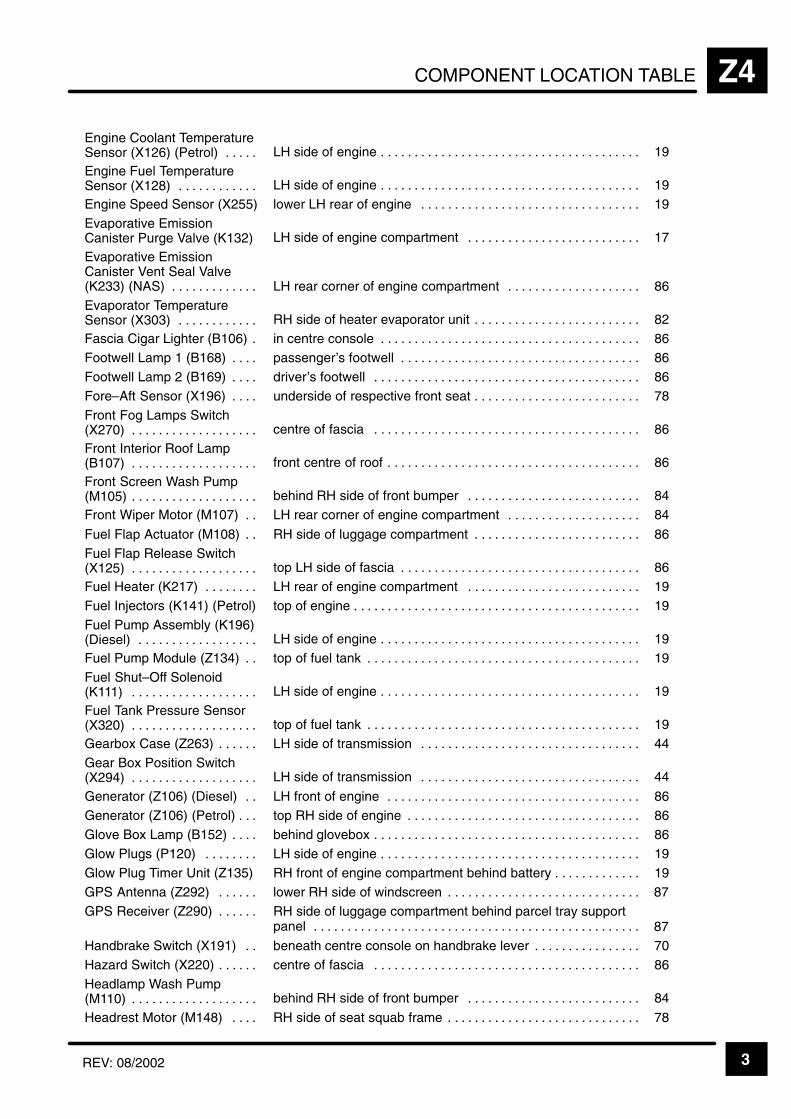
COMPONENT LOCATION TABLE Z4
3REV: 08/2002
ÁÁÁÁÁÁÁÁÁÁÁÁÁÁÁÁÁÁÁÁÁÁ
Engine Coolant TemperatureSensor (X126) (Petrol) . . . . .
ÁÁÁÁÁÁÁÁÁÁÁÁÁÁÁÁÁÁÁÁÁÁÁÁÁÁÁÁÁÁÁÁÁÁÁÁÁÁLH side of engine . . . . . . . . . . . . . . . . . . . . . . . . . . . . . . . . . . . . . . .
ÁÁÁÁÁÁÁÁÁÁÁÁÁÁÁÁ19ÁÁÁÁÁÁÁÁÁÁÁ
ÁÁÁÁÁÁÁÁÁÁÁÁÁÁÁÁÁÁÁÁÁÁ
Engine Fuel TemperatureSensor (X128) . . . . . . . . . . . .
ÁÁÁÁÁÁÁÁÁÁÁÁÁÁÁÁÁÁÁÁÁÁÁÁÁÁÁÁÁÁÁÁÁÁÁÁÁÁÁÁÁÁÁÁÁÁÁÁÁÁÁÁÁÁÁÁÁ
LH side of engine . . . . . . . . . . . . . . . . . . . . . . . . . . . . . . . . . . . . . . .
ÁÁÁÁÁÁÁÁÁÁÁÁÁÁÁÁÁÁÁÁÁÁÁÁ
19ÁÁÁÁÁÁÁÁÁÁÁÁÁÁÁÁÁÁÁÁÁÁ
Engine Speed Sensor (X255) ÁÁÁÁÁÁÁÁÁÁÁÁÁÁÁÁÁÁÁÁÁÁÁÁÁÁÁÁÁÁÁÁÁÁÁÁÁÁ
lower LH rear of engine . . . . . . . . . . . . . . . . . . . . . . . . . . . . . . . . . ÁÁÁÁÁÁÁÁÁÁÁÁÁÁÁÁ
19ÁÁÁÁÁÁÁÁÁÁÁÁÁÁÁÁÁÁÁÁÁÁÁÁÁÁÁÁÁÁÁÁÁ
Evaporative EmissionCanister Purge Valve (K132)
ÁÁÁÁÁÁÁÁÁÁÁÁÁÁÁÁÁÁÁÁÁÁÁÁÁÁÁÁÁÁÁÁÁÁÁÁÁÁÁÁÁÁÁÁÁÁÁÁÁÁÁÁÁÁÁÁÁ
LH side of engine compartment . . . . . . . . . . . . . . . . . . . . . . . . . . ÁÁÁÁÁÁÁÁÁÁÁÁÁÁÁÁÁÁÁÁÁÁÁÁ
17
ÁÁÁÁÁÁÁÁÁÁÁÁÁÁÁÁÁÁÁÁÁÁÁÁÁÁÁÁÁÁÁÁÁ
Evaporative EmissionCanister Vent Seal Valve(K233) (NAS) . . . . . . . . . . . . .
ÁÁÁÁÁÁÁÁÁÁÁÁÁÁÁÁÁÁÁÁÁÁÁÁÁÁÁÁÁÁÁÁÁÁÁÁÁÁÁÁÁÁÁÁÁÁÁÁÁÁÁÁÁÁÁÁÁ
LH rear corner of engine compartment . . . . . . . . . . . . . . . . . . . .
ÁÁÁÁÁÁÁÁÁÁÁÁÁÁÁÁÁÁÁÁÁÁÁÁ
86ÁÁÁÁÁÁÁÁÁÁÁÁÁÁÁÁÁÁÁÁÁÁÁÁÁÁÁÁÁÁÁÁÁ
Evaporator TemperatureSensor (X303) . . . . . . . . . . . .
ÁÁÁÁÁÁÁÁÁÁÁÁÁÁÁÁÁÁÁÁÁÁÁÁÁÁÁÁÁÁÁÁÁÁÁÁÁÁÁÁÁÁÁÁÁÁÁÁÁÁÁÁÁÁÁÁÁ
RH side of heater evaporator unit . . . . . . . . . . . . . . . . . . . . . . . . . ÁÁÁÁÁÁÁÁÁÁÁÁÁÁÁÁÁÁÁÁÁÁÁÁ
82
ÁÁÁÁÁÁÁÁÁÁÁÁÁÁÁÁÁÁÁÁÁÁ
Fascia Cigar Lighter (B106) . ÁÁÁÁÁÁÁÁÁÁÁÁÁÁÁÁÁÁÁÁÁÁÁÁÁÁÁÁÁÁÁÁÁÁÁÁÁÁ
in centre console . . . . . . . . . . . . . . . . . . . . . . . . . . . . . . . . . . . . . . . ÁÁÁÁÁÁÁÁÁÁÁÁÁÁÁÁ
86
ÁÁÁÁÁÁÁÁÁÁÁFootwell Lamp 1 (B168) . . . . ÁÁÁÁÁÁÁÁÁÁÁÁÁÁÁÁÁÁÁpassenger’s footwell . . . . . . . . . . . . . . . . . . . . . . . . . . . . . . . . . . . . ÁÁÁÁÁÁÁÁ86ÁÁÁÁÁÁÁÁÁÁÁÁÁÁÁÁÁÁÁÁÁÁFootwell Lamp 2 (B169) . . . .
ÁÁÁÁÁÁÁÁÁÁÁÁÁÁÁÁÁÁÁÁÁÁÁÁÁÁÁÁÁÁÁÁÁÁÁÁÁÁdriver’s footwell . . . . . . . . . . . . . . . . . . . . . . . . . . . . . . . . . . . . . . . .
ÁÁÁÁÁÁÁÁÁÁÁÁÁÁÁÁ86ÁÁÁÁÁÁÁÁÁÁÁ
ÁÁÁÁÁÁÁÁÁÁÁFore–Aft Sensor (X196) . . . . ÁÁÁÁÁÁÁÁÁÁÁÁÁÁÁÁÁÁÁÁÁÁÁÁÁÁÁÁÁÁÁÁÁÁÁÁÁÁunderside of respective front seat . . . . . . . . . . . . . . . . . . . . . . . . .
ÁÁÁÁÁÁÁÁÁÁÁÁÁÁÁÁ78ÁÁÁÁÁÁÁÁÁÁÁ
ÁÁÁÁÁÁÁÁÁÁÁÁÁÁÁÁÁÁÁÁÁÁ
Front Fog Lamps Switch(X270) . . . . . . . . . . . . . . . . . . .
ÁÁÁÁÁÁÁÁÁÁÁÁÁÁÁÁÁÁÁÁÁÁÁÁÁÁÁÁÁÁÁÁÁÁÁÁÁÁÁÁÁÁÁÁÁÁÁÁÁÁÁÁÁÁÁÁÁ
centre of fascia . . . . . . . . . . . . . . . . . . . . . . . . . . . . . . . . . . . . . . . .
ÁÁÁÁÁÁÁÁÁÁÁÁÁÁÁÁÁÁÁÁÁÁÁÁ
86ÁÁÁÁÁÁÁÁÁÁÁÁÁÁÁÁÁÁÁÁÁÁÁÁÁÁÁÁÁÁÁÁÁ
Front Interior Roof Lamp(B107) . . . . . . . . . . . . . . . . . . .
ÁÁÁÁÁÁÁÁÁÁÁÁÁÁÁÁÁÁÁÁÁÁÁÁÁÁÁÁÁÁÁÁÁÁÁÁÁÁÁÁÁÁÁÁÁÁÁÁÁÁÁÁÁÁÁÁÁ
front centre of roof . . . . . . . . . . . . . . . . . . . . . . . . . . . . . . . . . . . . . . ÁÁÁÁÁÁÁÁÁÁÁÁÁÁÁÁÁÁÁÁÁÁÁÁ
86
ÁÁÁÁÁÁÁÁÁÁÁÁÁÁÁÁÁÁÁÁÁÁ
Front Screen Wash Pump(M105) . . . . . . . . . . . . . . . . . . .
ÁÁÁÁÁÁÁÁÁÁÁÁÁÁÁÁÁÁÁÁÁÁÁÁÁÁÁÁÁÁÁÁÁÁÁÁÁÁ
behind RH side of front bumper . . . . . . . . . . . . . . . . . . . . . . . . . . ÁÁÁÁÁÁÁÁÁÁÁÁÁÁÁÁ
84ÁÁÁÁÁÁÁÁÁÁÁÁÁÁÁÁÁÁÁÁÁÁ
Front Wiper Motor (M107) . . ÁÁÁÁÁÁÁÁÁÁÁÁÁÁÁÁÁÁÁÁÁÁÁÁÁÁÁÁÁÁÁÁÁÁÁÁÁÁ
LH rear corner of engine compartment . . . . . . . . . . . . . . . . . . . . ÁÁÁÁÁÁÁÁÁÁÁÁÁÁÁÁ
84ÁÁÁÁÁÁÁÁÁÁÁÁÁÁÁÁÁÁÁÁÁÁ
Fuel Flap Actuator (M108) . . ÁÁÁÁÁÁÁÁÁÁÁÁÁÁÁÁÁÁÁÁÁÁÁÁÁÁÁÁÁÁÁÁÁÁÁÁÁÁ
RH side of luggage compartment . . . . . . . . . . . . . . . . . . . . . . . . . ÁÁÁÁÁÁÁÁÁÁÁÁÁÁÁÁ
86ÁÁÁÁÁÁÁÁÁÁÁÁÁÁÁÁÁÁÁÁÁÁÁÁÁÁÁÁÁÁÁÁÁ
Fuel Flap Release Switch(X125) . . . . . . . . . . . . . . . . . . .
ÁÁÁÁÁÁÁÁÁÁÁÁÁÁÁÁÁÁÁÁÁÁÁÁÁÁÁÁÁÁÁÁÁÁÁÁÁÁÁÁÁÁÁÁÁÁÁÁÁÁÁÁÁÁÁÁÁ
top LH side of fascia . . . . . . . . . . . . . . . . . . . . . . . . . . . . . . . . . . . .
ÁÁÁÁÁÁÁÁÁÁÁÁÁÁÁÁÁÁÁÁÁÁÁÁ
86
ÁÁÁÁÁÁÁÁÁÁÁÁÁÁÁÁÁÁÁÁÁÁ
Fuel Heater (K217) . . . . . . . . ÁÁÁÁÁÁÁÁÁÁÁÁÁÁÁÁÁÁÁÁÁÁÁÁÁÁÁÁÁÁÁÁÁÁÁÁÁÁ
LH rear of engine compartment . . . . . . . . . . . . . . . . . . . . . . . . . . ÁÁÁÁÁÁÁÁÁÁÁÁÁÁÁÁ
19
ÁÁÁÁÁÁÁÁÁÁÁÁÁÁÁÁÁÁÁÁÁÁ
Fuel Injectors (K141) (Petrol) ÁÁÁÁÁÁÁÁÁÁÁÁÁÁÁÁÁÁÁÁÁÁÁÁÁÁÁÁÁÁÁÁÁÁÁÁÁÁ
top of engine . . . . . . . . . . . . . . . . . . . . . . . . . . . . . . . . . . . . . . . . . . . ÁÁÁÁÁÁÁÁÁÁÁÁÁÁÁÁ
19
ÁÁÁÁÁÁÁÁÁÁÁÁÁÁÁÁÁÁÁÁÁÁ
Fuel Pump Assembly (K196)(Diesel) . . . . . . . . . . . . . . . . . .
ÁÁÁÁÁÁÁÁÁÁÁÁÁÁÁÁÁÁÁÁÁÁÁÁÁÁÁÁÁÁÁÁÁÁÁÁÁÁLH side of engine . . . . . . . . . . . . . . . . . . . . . . . . . . . . . . . . . . . . . . .
ÁÁÁÁÁÁÁÁÁÁÁÁÁÁÁÁ19ÁÁÁÁÁÁÁÁÁÁÁ
ÁÁÁÁÁÁÁÁÁÁÁFuel Pump Module (Z134) . .
ÁÁÁÁÁÁÁÁÁÁÁÁÁÁÁÁÁÁÁÁÁÁÁÁÁÁÁÁÁÁÁÁÁÁÁÁÁÁ
top of fuel tank . . . . . . . . . . . . . . . . . . . . . . . . . . . . . . . . . . . . . . . . . ÁÁÁÁÁÁÁÁÁÁÁÁÁÁÁÁ
19ÁÁÁÁÁÁÁÁÁÁÁÁÁÁÁÁÁÁÁÁÁÁÁÁÁÁÁÁÁÁÁÁÁ
Fuel Shut–Off Solenoid(K111) . . . . . . . . . . . . . . . . . . .
ÁÁÁÁÁÁÁÁÁÁÁÁÁÁÁÁÁÁÁÁÁÁÁÁÁÁÁÁÁÁÁÁÁÁÁÁÁÁÁÁÁÁÁÁÁÁÁÁÁÁÁÁÁÁÁÁÁ
LH side of engine . . . . . . . . . . . . . . . . . . . . . . . . . . . . . . . . . . . . . . .
ÁÁÁÁÁÁÁÁÁÁÁÁÁÁÁÁÁÁÁÁÁÁÁÁ
19ÁÁÁÁÁÁÁÁÁÁÁÁÁÁÁÁÁÁÁÁÁÁ
Fuel Tank Pressure Sensor(X320) . . . . . . . . . . . . . . . . . . .
ÁÁÁÁÁÁÁÁÁÁÁÁÁÁÁÁÁÁÁÁÁÁÁÁÁÁÁÁÁÁÁÁÁÁÁÁÁÁtop of fuel tank . . . . . . . . . . . . . . . . . . . . . . . . . . . . . . . . . . . . . . . . .
ÁÁÁÁÁÁÁÁÁÁÁÁÁÁÁÁ19ÁÁÁÁÁÁÁÁÁÁÁ
ÁÁÁÁÁÁÁÁÁÁÁGearbox Case (Z263) . . . . . . ÁÁÁÁÁÁÁÁÁÁÁÁÁÁÁÁÁÁÁÁÁÁÁÁÁÁÁÁÁÁÁÁÁÁÁÁÁÁLH side of transmission . . . . . . . . . . . . . . . . . . . . . . . . . . . . . . . . .
ÁÁÁÁÁÁÁÁÁÁÁÁÁÁÁÁ44ÁÁÁÁÁÁÁÁÁÁÁ
ÁÁÁÁÁÁÁÁÁÁÁÁÁÁÁÁÁÁÁÁÁÁ
Gear Box Position Switch(X294) . . . . . . . . . . . . . . . . . . .
ÁÁÁÁÁÁÁÁÁÁÁÁÁÁÁÁÁÁÁÁÁÁÁÁÁÁÁÁÁÁÁÁÁÁÁÁÁÁÁÁÁÁÁÁÁÁÁÁÁÁÁÁÁÁÁÁÁ
LH side of transmission . . . . . . . . . . . . . . . . . . . . . . . . . . . . . . . . .
ÁÁÁÁÁÁÁÁÁÁÁÁÁÁÁÁÁÁÁÁÁÁÁÁ
44ÁÁÁÁÁÁÁÁÁÁÁÁÁÁÁÁÁÁÁÁÁÁ
Generator (Z106) (Diesel) . . ÁÁÁÁÁÁÁÁÁÁÁÁÁÁÁÁÁÁÁÁÁÁÁÁÁÁÁÁÁÁÁÁÁÁÁÁÁÁ
LH front of engine . . . . . . . . . . . . . . . . . . . . . . . . . . . . . . . . . . . . . . ÁÁÁÁÁÁÁÁÁÁÁÁÁÁÁÁ
86ÁÁÁÁÁÁÁÁÁÁÁÁÁÁÁÁÁÁÁÁÁÁ
Generator (Z106) (Petrol) . . . ÁÁÁÁÁÁÁÁÁÁÁÁÁÁÁÁÁÁÁÁÁÁÁÁÁÁÁÁÁÁÁÁÁÁÁÁÁÁ
top RH side of engine . . . . . . . . . . . . . . . . . . . . . . . . . . . . . . . . . . . ÁÁÁÁÁÁÁÁÁÁÁÁÁÁÁÁ
86ÁÁÁÁÁÁÁÁÁÁÁÁÁÁÁÁÁÁÁÁÁÁ
Glove Box Lamp (B152) . . . . ÁÁÁÁÁÁÁÁÁÁÁÁÁÁÁÁÁÁÁÁÁÁÁÁÁÁÁÁÁÁÁÁÁÁÁÁÁÁ
behind glovebox . . . . . . . . . . . . . . . . . . . . . . . . . . . . . . . . . . . . . . . . ÁÁÁÁÁÁÁÁÁÁÁÁÁÁÁÁ
86ÁÁÁÁÁÁÁÁÁÁÁÁÁÁÁÁÁÁÁÁÁÁ
Glow Plugs (P120) . . . . . . . . ÁÁÁÁÁÁÁÁÁÁÁÁÁÁÁÁÁÁÁÁÁÁÁÁÁÁÁÁÁÁÁÁÁÁÁÁÁÁ
LH side of engine . . . . . . . . . . . . . . . . . . . . . . . . . . . . . . . . . . . . . . . ÁÁÁÁÁÁÁÁÁÁÁÁÁÁÁÁ
19
ÁÁÁÁÁÁÁÁÁÁÁÁÁÁÁÁÁÁÁÁÁÁ
Glow Plug Timer Unit (Z135) ÁÁÁÁÁÁÁÁÁÁÁÁÁÁÁÁÁÁÁÁÁÁÁÁÁÁÁÁÁÁÁÁÁÁÁÁÁÁ
RH front of engine compartment behind battery . . . . . . . . . . . . . ÁÁÁÁÁÁÁÁÁÁÁÁÁÁÁÁ
19
ÁÁÁÁÁÁÁÁÁÁÁÁÁÁÁÁÁÁÁÁÁÁ
GPS Antenna (Z292) . . . . . . ÁÁÁÁÁÁÁÁÁÁÁÁÁÁÁÁÁÁÁÁÁÁÁÁÁÁÁÁÁÁÁÁÁÁÁÁÁÁ
lower RH side of windscreen . . . . . . . . . . . . . . . . . . . . . . . . . . . . . ÁÁÁÁÁÁÁÁÁÁÁÁÁÁÁÁ
87
ÁÁÁÁÁÁÁÁÁÁÁÁÁÁÁÁÁÁÁÁÁÁ
GPS Receiver (Z290) . . . . . . ÁÁÁÁÁÁÁÁÁÁÁÁÁÁÁÁÁÁÁÁÁÁÁÁÁÁÁÁÁÁÁÁÁÁÁÁÁÁ
RH side of luggage compartment behind parcel tray supportpanel . . . . . . . . . . . . . . . . . . . . . . . . . . . . . . . . . . . . . . . . . . . . . . . . .
ÁÁÁÁÁÁÁÁÁÁÁÁÁÁÁÁ 87ÁÁÁÁÁÁÁÁÁÁÁ
ÁÁÁÁÁÁÁÁÁÁÁHandbrake Switch (X191) . . ÁÁÁÁÁÁÁÁÁÁÁÁÁÁÁÁÁÁÁÁÁÁÁÁÁÁÁÁÁÁÁÁÁÁÁÁÁÁbeneath centre console on handbrake lever . . . . . . . . . . . . . . . .
ÁÁÁÁÁÁÁÁÁÁÁÁÁÁÁÁ70ÁÁÁÁÁÁÁÁÁÁÁ
ÁÁÁÁÁÁÁÁÁÁÁHazard Switch (X220) . . . . . .
ÁÁÁÁÁÁÁÁÁÁÁÁÁÁÁÁÁÁÁÁÁÁÁÁÁÁÁÁÁÁÁÁÁÁÁÁÁÁ
centre of fascia . . . . . . . . . . . . . . . . . . . . . . . . . . . . . . . . . . . . . . . . ÁÁÁÁÁÁÁÁÁÁÁÁÁÁÁÁ
86ÁÁÁÁÁÁÁÁÁÁÁÁÁÁÁÁÁÁÁÁÁÁÁÁÁÁÁÁÁÁÁÁÁ
Headlamp Wash Pump(M110) . . . . . . . . . . . . . . . . . . .
ÁÁÁÁÁÁÁÁÁÁÁÁÁÁÁÁÁÁÁÁÁÁÁÁÁÁÁÁÁÁÁÁÁÁÁÁÁÁÁÁÁÁÁÁÁÁÁÁÁÁÁÁÁÁÁÁÁ
behind RH side of front bumper . . . . . . . . . . . . . . . . . . . . . . . . . .
ÁÁÁÁÁÁÁÁÁÁÁÁÁÁÁÁÁÁÁÁÁÁÁÁ
84ÁÁÁÁÁÁÁÁÁÁÁÁÁÁÁÁÁÁÁÁÁÁ
Headrest Motor (M148) . . . . ÁÁÁÁÁÁÁÁÁÁÁÁÁÁÁÁÁÁÁÁÁÁÁÁÁÁÁÁÁÁÁÁÁÁÁÁÁÁ
RH side of seat squab frame . . . . . . . . . . . . . . . . . . . . . . . . . . . . . ÁÁÁÁÁÁÁÁÁÁÁÁÁÁÁÁ
78
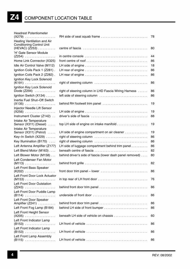
COMPONENT LOCATION TABLEZ4
4 REV: 08/2002
ÁÁÁÁÁÁÁÁÁÁÁÁÁÁÁÁÁÁÁÁ
Headrest Potentiometer(X279) . . . . . . . . . . . . . . . . . . .
ÁÁÁÁÁÁÁÁÁÁÁÁÁÁÁÁÁÁÁÁÁÁÁÁÁÁÁÁÁÁÁÁÁÁÁÁÁÁÁÁRH side of seat squab frame . . . . . . . . . . . . . . . . . . . . . . . . . . . . .
ÁÁÁÁÁÁÁÁÁÁÁÁÁÁ78ÁÁÁÁÁÁÁÁÁÁ
ÁÁÁÁÁÁÁÁÁÁÁÁÁÁÁÁÁÁÁÁÁÁÁÁÁÁÁÁÁÁ
Heating Ventilation and AirConditioning Control Unit(HEVAC) (Z253) . . . . . . . . . . .
ÁÁÁÁÁÁÁÁÁÁÁÁÁÁÁÁÁÁÁÁÁÁÁÁÁÁÁÁÁÁÁÁÁÁÁÁÁÁÁÁÁÁÁÁÁÁÁÁÁÁÁÁÁÁÁÁÁÁÁÁÁÁÁÁÁÁÁÁÁÁÁÁÁÁÁÁÁÁÁÁ
centre of fascia . . . . . . . . . . . . . . . . . . . . . . . . . . . . . . . . . . . . . . . .
ÁÁÁÁÁÁÁÁÁÁÁÁÁÁÁÁÁÁÁÁÁÁÁÁÁÁÁÁ
80
ÁÁÁÁÁÁÁÁÁÁÁÁÁÁÁÁÁÁÁÁ
’H’ Gate Sensor Module(Z254) . . . . . . . . . . . . . . . . . . .
ÁÁÁÁÁÁÁÁÁÁÁÁÁÁÁÁÁÁÁÁÁÁÁÁÁÁÁÁÁÁÁÁÁÁÁÁÁÁÁÁin centre console . . . . . . . . . . . . . . . . . . . . . . . . . . . . . . . . . . . . . . .
ÁÁÁÁÁÁÁÁÁÁÁÁÁÁ44ÁÁÁÁÁÁÁÁÁÁ
ÁÁÁÁÁÁÁÁÁÁHome Link Connector (X325)ÁÁÁÁÁÁÁÁÁÁÁÁÁÁÁÁÁÁÁÁÁÁÁÁÁÁÁÁÁÁÁÁÁÁÁÁÁÁÁÁfront centre of roof . . . . . . . . . . . . . . . . . . . . . . . . . . . . . . . . . . . . . .
ÁÁÁÁÁÁÁÁÁÁÁÁÁÁ86ÁÁÁÁÁÁÁÁÁÁ
ÁÁÁÁÁÁÁÁÁÁIdle Air Control Valve (M112)ÁÁÁÁÁÁÁÁÁÁÁÁÁÁÁÁÁÁÁÁÁÁÁÁÁÁÁÁÁÁÁÁÁÁÁÁÁÁÁÁLH side of engine . . . . . . . . . . . . . . . . . . . . . . . . . . . . . . . . . . . . . . .
ÁÁÁÁÁÁÁÁÁÁÁÁÁÁ18ÁÁÁÁÁÁÁÁÁÁ
ÁÁÁÁÁÁÁÁÁÁIgnition Coils Pack 1 (Z281) .
ÁÁÁÁÁÁÁÁÁÁÁÁÁÁÁÁÁÁÁÁÁÁÁÁÁÁÁÁÁÁÁÁÁÁÁÁÁÁÁÁ
LH rear of engine . . . . . . . . . . . . . . . . . . . . . . . . . . . . . . . . . . . . . . . ÁÁÁÁÁÁÁÁÁÁÁÁÁÁ
86ÁÁÁÁÁÁÁÁÁÁÁÁÁÁÁÁÁÁÁÁ
Ignition Coils Pack 2 (Z282) . ÁÁÁÁÁÁÁÁÁÁÁÁÁÁÁÁÁÁÁÁÁÁÁÁÁÁÁÁÁÁÁÁÁÁÁÁÁÁÁÁ
LH rear of engine . . . . . . . . . . . . . . . . . . . . . . . . . . . . . . . . . . . . . . . ÁÁÁÁÁÁÁÁÁÁÁÁÁÁ
86ÁÁÁÁÁÁÁÁÁÁÁÁÁÁÁÁÁÁÁÁÁÁÁÁÁÁÁÁÁÁ
Ignition Key Lock Solenoid(K191) . . . . . . . . . . . . . . . . . . .
ÁÁÁÁÁÁÁÁÁÁÁÁÁÁÁÁÁÁÁÁÁÁÁÁÁÁÁÁÁÁÁÁÁÁÁÁÁÁÁÁÁÁÁÁÁÁÁÁÁÁÁÁÁÁÁÁÁÁÁÁ
right of steering column . . . . . . . . . . . . . . . . . . . . . . . . . . . . . . . . .
ÁÁÁÁÁÁÁÁÁÁÁÁÁÁÁÁÁÁÁÁÁ
86
ÁÁÁÁÁÁÁÁÁÁÁÁÁÁÁÁÁÁÁÁ
Ignition Key Lock SolenoidDiode (Z294) . . . . . . . . . . . . .
ÁÁÁÁÁÁÁÁÁÁÁÁÁÁÁÁÁÁÁÁÁÁÁÁÁÁÁÁÁÁÁÁÁÁÁÁÁÁÁÁright of steering column in LHD Fascia Wiring Harness . . . . . .
ÁÁÁÁÁÁÁÁÁÁÁÁÁÁ86ÁÁÁÁÁÁÁÁÁÁ
ÁÁÁÁÁÁÁÁÁÁIgnition Switch (X134) . . . . . . ÁÁÁÁÁÁÁÁÁÁÁÁÁÁÁÁÁÁÁÁÁÁÁÁÁÁÁÁÁÁÁÁÁÁÁÁÁÁÁÁleft side of steering column . . . . . . . . . . . . . . . . . . . . . . . . . . . . . .
ÁÁÁÁÁÁÁÁÁÁÁÁÁÁ86ÁÁÁÁÁÁÁÁÁÁ
ÁÁÁÁÁÁÁÁÁÁÁÁÁÁÁÁÁÁÁÁ
Inertia Fuel Shut–Off Switch(X135) . . . . . . . . . . . . . . . . . . .
ÁÁÁÁÁÁÁÁÁÁÁÁÁÁÁÁÁÁÁÁÁÁÁÁÁÁÁÁÁÁÁÁÁÁÁÁÁÁÁÁÁÁÁÁÁÁÁÁÁÁÁÁÁÁÁÁÁÁÁÁ
behind RH footwell trim panel . . . . . . . . . . . . . . . . . . . . . . . . . . . .
ÁÁÁÁÁÁÁÁÁÁÁÁÁÁÁÁÁÁÁÁÁ
19ÁÁÁÁÁÁÁÁÁÁÁÁÁÁÁÁÁÁÁÁÁÁÁÁÁÁÁÁÁÁ
Injector Needle Lift Sensor(X256) . . . . . . . . . . . . . . . . . . .
ÁÁÁÁÁÁÁÁÁÁÁÁÁÁÁÁÁÁÁÁÁÁÁÁÁÁÁÁÁÁÁÁÁÁÁÁÁÁÁÁÁÁÁÁÁÁÁÁÁÁÁÁÁÁÁÁÁÁÁÁ
LH side of engine . . . . . . . . . . . . . . . . . . . . . . . . . . . . . . . . . . . . . . . ÁÁÁÁÁÁÁÁÁÁÁÁÁÁÁÁÁÁÁÁÁ
19
ÁÁÁÁÁÁÁÁÁÁÁÁÁÁÁÁÁÁÁÁ
Instrument Cluster (Z142) . . ÁÁÁÁÁÁÁÁÁÁÁÁÁÁÁÁÁÁÁÁÁÁÁÁÁÁÁÁÁÁÁÁÁÁÁÁÁÁÁÁ
driver’s side of fascia . . . . . . . . . . . . . . . . . . . . . . . . . . . . . . . . . . . ÁÁÁÁÁÁÁÁÁÁÁÁÁÁ
88
ÁÁÁÁÁÁÁÁÁÁÁÁÁÁÁÁÁÁÁÁ
Intake Air TemperatureSensor (X311) (Diesel) . . . . .
ÁÁÁÁÁÁÁÁÁÁÁÁÁÁÁÁÁÁÁÁÁÁÁÁÁÁÁÁÁÁÁÁÁÁÁÁÁÁÁÁ
top LH side of engine on intake manifold . . . . . . . . . . . . . . . . . . . ÁÁÁÁÁÁÁÁÁÁÁÁÁÁ
19ÁÁÁÁÁÁÁÁÁÁÁÁÁÁÁÁÁÁÁÁÁÁÁÁÁÁÁÁÁÁ
Intake Air TemperatureSensor (X311) (Petrol) . . . . .
ÁÁÁÁÁÁÁÁÁÁÁÁÁÁÁÁÁÁÁÁÁÁÁÁÁÁÁÁÁÁÁÁÁÁÁÁÁÁÁÁÁÁÁÁÁÁÁÁÁÁÁÁÁÁÁÁÁÁÁÁ
LH side of engine compartment on air cleaner . . . . . . . . . . . . . .
ÁÁÁÁÁÁÁÁÁÁÁÁÁÁÁÁÁÁÁÁÁ
19ÁÁÁÁÁÁÁÁÁÁÁÁÁÁÁÁÁÁÁÁ
Key–In Switch (X229) . . . . . . ÁÁÁÁÁÁÁÁÁÁÁÁÁÁÁÁÁÁÁÁÁÁÁÁÁÁÁÁÁÁÁÁÁÁÁÁÁÁÁÁ
right of steering column . . . . . . . . . . . . . . . . . . . . . . . . . . . . . . . . . ÁÁÁÁÁÁÁÁÁÁÁÁÁÁ
86ÁÁÁÁÁÁÁÁÁÁÁÁÁÁÁÁÁÁÁÁ
Key Illumination (B170) . . . . ÁÁÁÁÁÁÁÁÁÁÁÁÁÁÁÁÁÁÁÁÁÁÁÁÁÁÁÁÁÁÁÁÁÁÁÁÁÁÁÁ
right of steering column . . . . . . . . . . . . . . . . . . . . . . . . . . . . . . . . . ÁÁÁÁÁÁÁÁÁÁÁÁÁÁ
86
ÁÁÁÁÁÁÁÁÁÁÁÁÁÁÁÁÁÁÁÁ
Left Antenna Amplifier (Z177)ÁÁÁÁÁÁÁÁÁÁÁÁÁÁÁÁÁÁÁÁÁÁÁÁÁÁÁÁÁÁÁÁÁÁÁÁÁÁÁÁ
LH side of luggage compartment behind trim panel . . . . . . . . . . ÁÁÁÁÁÁÁÁÁÁÁÁÁÁ
86
ÁÁÁÁÁÁÁÁÁÁÁÁÁÁÁÁÁÁÁÁ
Left Blend Motor (M163) . . . . ÁÁÁÁÁÁÁÁÁÁÁÁÁÁÁÁÁÁÁÁÁÁÁÁÁÁÁÁÁÁÁÁÁÁÁÁÁÁÁÁ
beneath centre of fascia . . . . . . . . . . . . . . . . . . . . . . . . . . . . . . . . . ÁÁÁÁÁÁÁÁÁÁÁÁÁÁ
82
ÁÁÁÁÁÁÁÁÁÁÁÁÁÁÁÁÁÁÁÁ
Left Blower Motor (M158) . . . ÁÁÁÁÁÁÁÁÁÁÁÁÁÁÁÁÁÁÁÁÁÁÁÁÁÁÁÁÁÁÁÁÁÁÁÁÁÁÁÁ
behind driver’s side of fascia (lower dash panel removed) . . . . ÁÁÁÁÁÁÁÁÁÁÁÁÁÁ
80
ÁÁÁÁÁÁÁÁÁÁÁÁÁÁÁÁÁÁÁÁ
Left Condenser Fan Motor(M113) . . . . . . . . . . . . . . . . . . .
ÁÁÁÁÁÁÁÁÁÁÁÁÁÁÁÁÁÁÁÁÁÁÁÁÁÁÁÁÁÁÁÁÁÁÁÁÁÁÁÁ
behind front grille . . . . . . . . . . . . . . . . . . . . . . . . . . . . . . . . . . . . . . . ÁÁÁÁÁÁÁÁÁÁÁÁÁÁ
82ÁÁÁÁÁÁÁÁÁÁÁÁÁÁÁÁÁÁÁÁÁÁÁÁÁÁÁÁÁÁ
Left Front Bass Speaker(K202) . . . . . . . . . . . . . . . . . . .
ÁÁÁÁÁÁÁÁÁÁÁÁÁÁÁÁÁÁÁÁÁÁÁÁÁÁÁÁÁÁÁÁÁÁÁÁÁÁÁÁÁÁÁÁÁÁÁÁÁÁÁÁÁÁÁÁÁÁÁÁ
front door trim panel – lower . . . . . . . . . . . . . . . . . . . . . . . . . . . . .
ÁÁÁÁÁÁÁÁÁÁÁÁÁÁÁÁÁÁÁÁÁ
86ÁÁÁÁÁÁÁÁÁÁÁÁÁÁÁÁÁÁÁÁ
Left Front Door Lock Actuator(M153) . . . . . . . . . . . . . . . . . . .
ÁÁÁÁÁÁÁÁÁÁÁÁÁÁÁÁÁÁÁÁÁÁÁÁÁÁÁÁÁÁÁÁÁÁÁÁÁÁÁÁin top rear of LH front door . . . . . . . . . . . . . . . . . . . . . . . . . . . . . . .
ÁÁÁÁÁÁÁÁÁÁÁÁÁÁ76ÁÁÁÁÁÁÁÁÁÁ
ÁÁÁÁÁÁÁÁÁÁÁÁÁÁÁÁÁÁÁÁ
Left Front Door Outstation(Z243) . . . . . . . . . . . . . . . . . . .
ÁÁÁÁÁÁÁÁÁÁÁÁÁÁÁÁÁÁÁÁÁÁÁÁÁÁÁÁÁÁÁÁÁÁÁÁÁÁÁÁÁÁÁÁÁÁÁÁÁÁÁÁÁÁÁÁÁÁÁÁ
behind front door trim panel . . . . . . . . . . . . . . . . . . . . . . . . . . . . . .
ÁÁÁÁÁÁÁÁÁÁÁÁÁÁÁÁÁÁÁÁÁ
86ÁÁÁÁÁÁÁÁÁÁÁÁÁÁÁÁÁÁÁÁÁÁÁÁÁÁÁÁÁÁ
Left Front Door Puddle Lamp(B114) . . . . . . . . . . . . . . . . . . .
ÁÁÁÁÁÁÁÁÁÁÁÁÁÁÁÁÁÁÁÁÁÁÁÁÁÁÁÁÁÁÁÁÁÁÁÁÁÁÁÁÁÁÁÁÁÁÁÁÁÁÁÁÁÁÁÁÁÁÁÁ
underside of front door . . . . . . . . . . . . . . . . . . . . . . . . . . . . . . . . . .
ÁÁÁÁÁÁÁÁÁÁÁÁÁÁÁÁÁÁÁÁÁ
86
ÁÁÁÁÁÁÁÁÁÁÁÁÁÁÁÁÁÁÁÁ
Left Front Door SpeakerAmplifier (Z241) . . . . . . . . . . .
ÁÁÁÁÁÁÁÁÁÁÁÁÁÁÁÁÁÁÁÁÁÁÁÁÁÁÁÁÁÁÁÁÁÁÁÁÁÁÁÁbehind front door trim panel . . . . . . . . . . . . . . . . . . . . . . . . . . . . . .
ÁÁÁÁÁÁÁÁÁÁÁÁÁÁ86ÁÁÁÁÁÁÁÁÁÁ
ÁÁÁÁÁÁÁÁÁÁLeft Front Fog Lamp (B184)ÁÁÁÁÁÁÁÁÁÁÁÁÁÁÁÁÁÁÁÁÁÁÁÁÁÁÁÁÁÁÁÁÁÁÁÁÁÁÁÁbehind LH side of front bumper . . . . . . . . . . . . . . . . . . . . . . . . . . .
ÁÁÁÁÁÁÁÁÁÁÁÁÁÁ86ÁÁÁÁÁÁÁÁÁÁ
ÁÁÁÁÁÁÁÁÁÁÁÁÁÁÁÁÁÁÁÁ
Left Front Height Sensor(X205) . . . . . . . . . . . . . . . . . . .
ÁÁÁÁÁÁÁÁÁÁÁÁÁÁÁÁÁÁÁÁÁÁÁÁÁÁÁÁÁÁÁÁÁÁÁÁÁÁÁÁÁÁÁÁÁÁÁÁÁÁÁÁÁÁÁÁÁÁÁÁ
beneath LH side of vehicle on chassis . . . . . . . . . . . . . . . . . . . . .
ÁÁÁÁÁÁÁÁÁÁÁÁÁÁÁÁÁÁÁÁÁ
60ÁÁÁÁÁÁÁÁÁÁÁÁÁÁÁÁÁÁÁÁÁÁÁÁÁÁÁÁÁÁ
Left Front Indicator Lamp(B153) . . . . . . . . . . . . . . . . . . .
ÁÁÁÁÁÁÁÁÁÁÁÁÁÁÁÁÁÁÁÁÁÁÁÁÁÁÁÁÁÁÁÁÁÁÁÁÁÁÁÁÁÁÁÁÁÁÁÁÁÁÁÁÁÁÁÁÁÁÁÁ
LH front of vehicle . . . . . . . . . . . . . . . . . . . . . . . . . . . . . . . . . . . . . . ÁÁÁÁÁÁÁÁÁÁÁÁÁÁÁÁÁÁÁÁÁ
86
ÁÁÁÁÁÁÁÁÁÁÁÁÁÁÁÁÁÁÁÁ
Left Front Indicator Lamp(B153) . . . . . . . . . . . . . . . . . . .
ÁÁÁÁÁÁÁÁÁÁÁÁÁÁÁÁÁÁÁÁÁÁÁÁÁÁÁÁÁÁÁÁÁÁÁÁÁÁÁÁ
LH front of vehicle . . . . . . . . . . . . . . . . . . . . . . . . . . . . . . . . . . . . . . ÁÁÁÁÁÁÁÁÁÁÁÁÁÁ
86ÁÁÁÁÁÁÁÁÁÁÁÁÁÁÁÁÁÁÁÁÁÁÁÁÁÁÁÁÁÁ
Left Front Lamp Assembly(B115) . . . . . . . . . . . . . . . . . . .
ÁÁÁÁÁÁÁÁÁÁÁÁÁÁÁÁÁÁÁÁÁÁÁÁÁÁÁÁÁÁÁÁÁÁÁÁÁÁÁÁÁÁÁÁÁÁÁÁÁÁÁÁÁÁÁÁÁÁÁÁ
LH front of vehicle . . . . . . . . . . . . . . . . . . . . . . . . . . . . . . . . . . . . . .
ÁÁÁÁÁÁÁÁÁÁÁÁÁÁÁÁÁÁÁÁÁ
86

COMPONENT LOCATION TABLE Z4
5REV: 08/2002
ÁÁÁÁÁÁÁÁÁÁÁÁÁÁÁÁÁÁÁÁÁÁ
Left Front Midrange FilterCapacitor (Z247) . . . . . . . . . .
ÁÁÁÁÁÁÁÁÁÁÁÁÁÁÁÁÁÁÁÁÁÁÁÁÁÁÁÁÁÁÁÁÁÁÁÁÁÁbehind front door trim panel in Left Front Midrange Speaker . .
ÁÁÁÁÁÁÁÁÁÁÁÁÁÁÁÁ86ÁÁÁÁÁÁÁÁÁÁÁ
ÁÁÁÁÁÁÁÁÁÁÁÁÁÁÁÁÁÁÁÁÁÁ
Left Front Midrange Speaker(K200) . . . . . . . . . . . . . . . . . . .
ÁÁÁÁÁÁÁÁÁÁÁÁÁÁÁÁÁÁÁÁÁÁÁÁÁÁÁÁÁÁÁÁÁÁÁÁÁÁÁÁÁÁÁÁÁÁÁÁÁÁÁÁÁÁÁÁÁ
front door trim panel – centre . . . . . . . . . . . . . . . . . . . . . . . . . . . .
ÁÁÁÁÁÁÁÁÁÁÁÁÁÁÁÁÁÁÁÁÁÁÁÁ
86ÁÁÁÁÁÁÁÁÁÁÁÁÁÁÁÁÁÁÁÁÁÁÁÁÁÁÁÁÁÁÁÁÁ
Left Front Seat HeightAdjuster (X331) . . . . . . . . . . .
ÁÁÁÁÁÁÁÁÁÁÁÁÁÁÁÁÁÁÁÁÁÁÁÁÁÁÁÁÁÁÁÁÁÁÁÁÁÁÁÁÁÁÁÁÁÁÁÁÁÁÁÁÁÁÁÁÁ
beneath LH front seat . . . . . . . . . . . . . . . . . . . . . . . . . . . . . . . . . . . ÁÁÁÁÁÁÁÁÁÁÁÁÁÁÁÁÁÁÁÁÁÁÁÁ
78
ÁÁÁÁÁÁÁÁÁÁÁÁÁÁÁÁÁÁÁÁÁÁ
Left Front Tweeter (K197) . . ÁÁÁÁÁÁÁÁÁÁÁÁÁÁÁÁÁÁÁÁÁÁÁÁÁÁÁÁÁÁÁÁÁÁÁÁÁÁ
front door cheater panel . . . . . . . . . . . . . . . . . . . . . . . . . . . . . . . . . ÁÁÁÁÁÁÁÁÁÁÁÁÁÁÁÁ
86
ÁÁÁÁÁÁÁÁÁÁÁÁÁÁÁÁÁÁÁÁÁÁ
Left Front Wheel SpeedSensor (X137) . . . . . . . . . . . .
ÁÁÁÁÁÁÁÁÁÁÁÁÁÁÁÁÁÁÁÁÁÁÁÁÁÁÁÁÁÁÁÁÁÁÁÁÁÁ
behind LH front wheel . . . . . . . . . . . . . . . . . . . . . . . . . . . . . . . . . . . ÁÁÁÁÁÁÁÁÁÁÁÁÁÁÁÁ
70ÁÁÁÁÁÁÁÁÁÁÁÁÁÁÁÁÁÁÁÁÁÁÁÁÁÁÁÁÁÁÁÁÁ
Left Front Window Motor(M130) . . . . . . . . . . . . . . . . . . .
ÁÁÁÁÁÁÁÁÁÁÁÁÁÁÁÁÁÁÁÁÁÁÁÁÁÁÁÁÁÁÁÁÁÁÁÁÁÁÁÁÁÁÁÁÁÁÁÁÁÁÁÁÁÁÁÁÁ
behind front door trim panel . . . . . . . . . . . . . . . . . . . . . . . . . . . . . .
ÁÁÁÁÁÁÁÁÁÁÁÁÁÁÁÁÁÁÁÁÁÁÁÁ
86ÁÁÁÁÁÁÁÁÁÁÁÁÁÁÁÁÁÁÁÁÁÁ
Left Headlamp (B116) . . . . . . ÁÁÁÁÁÁÁÁÁÁÁÁÁÁÁÁÁÁÁÁÁÁÁÁÁÁÁÁÁÁÁÁÁÁÁÁÁÁ
LH front of vehicle . . . . . . . . . . . . . . . . . . . . . . . . . . . . . . . . . . . . . . ÁÁÁÁÁÁÁÁÁÁÁÁÁÁÁÁ
86
ÁÁÁÁÁÁÁÁÁÁÁÁÁÁÁÁÁÁÁÁÁÁ
Left Headlamp Wiper Motor(M156) . . . . . . . . . . . . . . . . . . .
ÁÁÁÁÁÁÁÁÁÁÁÁÁÁÁÁÁÁÁÁÁÁÁÁÁÁÁÁÁÁÁÁÁÁÁÁÁÁLH front of vehicle . . . . . . . . . . . . . . . . . . . . . . . . . . . . . . . . . . . . . .
ÁÁÁÁÁÁÁÁÁÁÁÁÁÁÁÁ84ÁÁÁÁÁÁÁÁÁÁÁ
ÁÁÁÁÁÁÁÁÁÁÁÁÁÁÁÁÁÁÁÁÁÁ
Left Heated Oxygen Sensor(Post Catalyst) (X289) . . . . .
ÁÁÁÁÁÁÁÁÁÁÁÁÁÁÁÁÁÁÁÁÁÁÁÁÁÁÁÁÁÁÁÁÁÁÁÁÁÁÁÁÁÁÁÁÁÁÁÁÁÁÁÁÁÁÁÁÁ
on left intermediate pipe . . . . . . . . . . . . . . . . . . . . . . . . . . . . . . . . .
ÁÁÁÁÁÁÁÁÁÁÁÁÁÁÁÁÁÁÁÁÁÁÁÁ
19ÁÁÁÁÁÁÁÁÁÁÁÁÁÁÁÁÁÁÁÁÁÁÁÁÁÁÁÁÁÁÁÁÁ
Left Heated Oxygen Sensor(X139) . . . . . . . . . . . . . . . . . . .
ÁÁÁÁÁÁÁÁÁÁÁÁÁÁÁÁÁÁÁÁÁÁÁÁÁÁÁÁÁÁÁÁÁÁÁÁÁÁÁÁÁÁÁÁÁÁÁÁÁÁÁÁÁÁÁÁÁ
on left exhaust downpipe . . . . . . . . . . . . . . . . . . . . . . . . . . . . . . . . ÁÁÁÁÁÁÁÁÁÁÁÁÁÁÁÁÁÁÁÁÁÁÁÁ
19
ÁÁÁÁÁÁÁÁÁÁÁÁÁÁÁÁÁÁÁÁÁÁ
Left Horn (K128) . . . . . . . . . . ÁÁÁÁÁÁÁÁÁÁÁÁÁÁÁÁÁÁÁÁÁÁÁÁÁÁÁÁÁÁÁÁÁÁÁÁÁÁ
LH front of engine compartment . . . . . . . . . . . . . . . . . . . . . . . . . . ÁÁÁÁÁÁÁÁÁÁÁÁÁÁÁÁ
86
ÁÁÁÁÁÁÁÁÁÁÁÁÁÁÁÁÁÁÁÁÁÁ
Left Interior Lights (B180) . . . ÁÁÁÁÁÁÁÁÁÁÁÁÁÁÁÁÁÁÁÁÁÁÁÁÁÁÁÁÁÁÁÁÁÁÁÁÁÁ
LH centre of headlining . . . . . . . . . . . . . . . . . . . . . . . . . . . . . . . . . . ÁÁÁÁÁÁÁÁÁÁÁÁÁÁÁÁ
86
ÁÁÁÁÁÁÁÁÁÁÁLeft Knock Sensor (X295) . . ÁÁÁÁÁÁÁÁÁÁÁÁÁÁÁÁÁÁÁlower LH side of engine . . . . . . . . . . . . . . . . . . . . . . . . . . . . . . . . . ÁÁÁÁÁÁÁÁ19ÁÁÁÁÁÁÁÁÁÁÁÁÁÁÁÁÁÁÁÁÁÁLeft Lumbar Pump (M147) . .
ÁÁÁÁÁÁÁÁÁÁÁÁÁÁÁÁÁÁÁÁÁÁÁÁÁÁÁÁÁÁÁÁÁÁÁÁÁÁRH side of seat squab frame . . . . . . . . . . . . . . . . . . . . . . . . . . . . .
ÁÁÁÁÁÁÁÁÁÁÁÁÁÁÁÁ78ÁÁÁÁÁÁÁÁÁÁÁ
ÁÁÁÁÁÁÁÁÁÁÁLeft Memory Mirror (M152) . ÁÁÁÁÁÁÁÁÁÁÁÁÁÁÁÁÁÁÁÁÁÁÁÁÁÁÁÁÁÁÁÁÁÁÁÁÁÁLH front door . . . . . . . . . . . . . . . . . . . . . . . . . . . . . . . . . . . . . . . . . .
ÁÁÁÁÁÁÁÁÁÁÁÁÁÁÁÁ76ÁÁÁÁÁÁÁÁÁÁÁ
ÁÁÁÁÁÁÁÁÁÁÁLeft Memory Switch (X278) . ÁÁÁÁÁÁÁÁÁÁÁÁÁÁÁÁÁÁÁÁÁÁÁÁÁÁÁÁÁÁÁÁÁÁÁÁÁÁon side of respective front seat . . . . . . . . . . . . . . . . . . . . . . . . . . .
ÁÁÁÁÁÁÁÁÁÁÁÁÁÁÁÁ78ÁÁÁÁÁÁÁÁÁÁÁ
ÁÁÁÁÁÁÁÁÁÁÁLeft Mirror Actuator (M115) . ÁÁÁÁÁÁÁÁÁÁÁÁÁÁÁÁÁÁÁÁÁÁÁÁÁÁÁÁÁÁÁÁÁÁÁÁÁÁLH front door . . . . . . . . . . . . . . . . . . . . . . . . . . . . . . . . . . . . . . . . . .
ÁÁÁÁÁÁÁÁÁÁÁÁÁÁÁÁ76
ÁÁÁÁÁÁÁÁÁÁÁÁÁÁÁÁÁÁÁÁÁÁÁÁÁÁÁÁÁÁÁÁÁ
Left Non–Memory SeatPower Relay 1 (K213) . . . . . .
ÁÁÁÁÁÁÁÁÁÁÁÁÁÁÁÁÁÁÁÁÁÁÁÁÁÁÁÁÁÁÁÁÁÁÁÁÁÁÁÁÁÁÁÁÁÁÁÁÁÁÁÁÁÁÁÁÁ
underside of LH front seat . . . . . . . . . . . . . . . . . . . . . . . . . . . . . . .
ÁÁÁÁÁÁÁÁÁÁÁÁÁÁÁÁÁÁÁÁÁÁÁÁ
78ÁÁÁÁÁÁÁÁÁÁÁÁÁÁÁÁÁÁÁÁÁÁ
Left Non–Memory SeatPower Relay 2 (K215) . . . . . .
ÁÁÁÁÁÁÁÁÁÁÁÁÁÁÁÁÁÁÁÁÁÁÁÁÁÁÁÁÁÁÁÁÁÁÁÁÁÁunderside of LH front seat . . . . . . . . . . . . . . . . . . . . . . . . . . . . . . .
ÁÁÁÁÁÁÁÁÁÁÁÁÁÁÁÁ78ÁÁÁÁÁÁÁÁÁÁÁ
ÁÁÁÁÁÁÁÁÁÁÁÁÁÁÁÁÁÁÁÁÁÁ
Left Number Plate Lamp(B120) . . . . . . . . . . . . . . . . . . .
ÁÁÁÁÁÁÁÁÁÁÁÁÁÁÁÁÁÁÁÁÁÁÁÁÁÁÁÁÁÁÁÁÁÁÁÁÁÁÁÁÁÁÁÁÁÁÁÁÁÁÁÁÁÁÁÁÁ
rear of vehicle, on tailgate . . . . . . . . . . . . . . . . . . . . . . . . . . . . . . .
ÁÁÁÁÁÁÁÁÁÁÁÁÁÁÁÁÁÁÁÁÁÁÁÁ
86ÁÁÁÁÁÁÁÁÁÁÁÁÁÁÁÁÁÁÁÁÁÁÁÁÁÁÁÁÁÁÁÁÁ
Left Rear Bass Speaker(K209) . . . . . . . . . . . . . . . . . . .
ÁÁÁÁÁÁÁÁÁÁÁÁÁÁÁÁÁÁÁÁÁÁÁÁÁÁÁÁÁÁÁÁÁÁÁÁÁÁÁÁÁÁÁÁÁÁÁÁÁÁÁÁÁÁÁÁÁ
rear door trim panel – lower . . . . . . . . . . . . . . . . . . . . . . . . . . . . . .
ÁÁÁÁÁÁÁÁÁÁÁÁÁÁÁÁÁÁÁÁÁÁÁÁ
86
ÁÁÁÁÁÁÁÁÁÁÁÁÁÁÁÁÁÁÁÁÁÁ
Left Rear Door Lock Actuator(M149) . . . . . . . . . . . . . . . . . . .
ÁÁÁÁÁÁÁÁÁÁÁÁÁÁÁÁÁÁÁÁÁÁÁÁÁÁÁÁÁÁÁÁÁÁÁÁÁÁin top of LH rear door . . . . . . . . . . . . . . . . . . . . . . . . . . . . . . . . . . .
ÁÁÁÁÁÁÁÁÁÁÁÁÁÁÁÁ76ÁÁÁÁÁÁÁÁÁÁÁ
ÁÁÁÁÁÁÁÁÁÁÁÁÁÁÁÁÁÁÁÁÁÁ
Left Rear Door Puddle Lamp(B149) . . . . . . . . . . . . . . . . . . .
ÁÁÁÁÁÁÁÁÁÁÁÁÁÁÁÁÁÁÁÁÁÁÁÁÁÁÁÁÁÁÁÁÁÁÁÁÁÁÁÁÁÁÁÁÁÁÁÁÁÁÁÁÁÁÁÁÁ
underside of rear door . . . . . . . . . . . . . . . . . . . . . . . . . . . . . . . . . .
ÁÁÁÁÁÁÁÁÁÁÁÁÁÁÁÁÁÁÁÁÁÁÁÁ
86ÁÁÁÁÁÁÁÁÁÁÁÁÁÁÁÁÁÁÁÁÁÁÁÁÁÁÁÁÁÁÁÁÁ
Left Rear Door SpeakerAmplifier (Z245) . . . . . . . . . . .
ÁÁÁÁÁÁÁÁÁÁÁÁÁÁÁÁÁÁÁÁÁÁÁÁÁÁÁÁÁÁÁÁÁÁÁÁÁÁÁÁÁÁÁÁÁÁÁÁÁÁÁÁÁÁÁÁÁ
behind rear door trim panel . . . . . . . . . . . . . . . . . . . . . . . . . . . . . . ÁÁÁÁÁÁÁÁÁÁÁÁÁÁÁÁÁÁÁÁÁÁÁÁ
86
ÁÁÁÁÁÁÁÁÁÁÁÁÁÁÁÁÁÁÁÁÁÁ
Left Rear Height Sensor(X206) . . . . . . . . . . . . . . . . . . .
ÁÁÁÁÁÁÁÁÁÁÁÁÁÁÁÁÁÁÁÁÁÁÁÁÁÁÁÁÁÁÁÁÁÁÁÁÁÁbeneath LH side of vehicle on chassis . . . . . . . . . . . . . . . . . . . . .
ÁÁÁÁÁÁÁÁÁÁÁÁÁÁÁÁ60ÁÁÁÁÁÁÁÁÁÁÁ
ÁÁÁÁÁÁÁÁÁÁÁÁÁÁÁÁÁÁÁÁÁÁ
Left Rear Lamp Assembly(B175) . . . . . . . . . . . . . . . . . . .
ÁÁÁÁÁÁÁÁÁÁÁÁÁÁÁÁÁÁÁÁÁÁÁÁÁÁÁÁÁÁÁÁÁÁÁÁÁÁÁÁÁÁÁÁÁÁÁÁÁÁÁÁÁÁÁÁÁ
LH rear of vehicle . . . . . . . . . . . . . . . . . . . . . . . . . . . . . . . . . . . . . .
ÁÁÁÁÁÁÁÁÁÁÁÁÁÁÁÁÁÁÁÁÁÁÁÁ
86ÁÁÁÁÁÁÁÁÁÁÁÁÁÁÁÁÁÁÁÁÁÁ
Left Rear Midrange FilterCapacitor (Z239) . . . . . . . . . .
ÁÁÁÁÁÁÁÁÁÁÁÁÁÁÁÁÁÁÁÁÁÁÁÁÁÁÁÁÁÁÁÁÁÁÁÁÁÁbehind rear door trim panel in Left Rear Midrange Speaker . . .
ÁÁÁÁÁÁÁÁÁÁÁÁÁÁÁÁ86
ÁÁÁÁÁÁÁÁÁÁÁÁÁÁÁÁÁÁÁÁÁÁ
Left Rear Midrange Speaker(K211) . . . . . . . . . . . . . . . . . . .
ÁÁÁÁÁÁÁÁÁÁÁÁÁÁÁÁÁÁÁÁÁÁÁÁÁÁÁÁÁÁÁÁÁÁÁÁÁÁ
rear door trim panel – centre . . . . . . . . . . . . . . . . . . . . . . . . . . . . . ÁÁÁÁÁÁÁÁÁÁÁÁÁÁÁÁ
86ÁÁÁÁÁÁÁÁÁÁÁÁÁÁÁÁÁÁÁÁÁÁÁÁÁÁÁÁÁÁÁÁÁ
Left Rear Wheel SpeedSensor (X140) . . . . . . . . . . . .
ÁÁÁÁÁÁÁÁÁÁÁÁÁÁÁÁÁÁÁÁÁÁÁÁÁÁÁÁÁÁÁÁÁÁÁÁÁÁÁÁÁÁÁÁÁÁÁÁÁÁÁÁÁÁÁÁÁ
behind LH rear wheel . . . . . . . . . . . . . . . . . . . . . . . . . . . . . . . . . . .
ÁÁÁÁÁÁÁÁÁÁÁÁÁÁÁÁÁÁÁÁÁÁÁÁ
70
ÁÁÁÁÁÁÁÁÁÁÁÁÁÁÁÁÁÁÁÁÁÁ
Left Rear Window DoorSwitch (X188) . . . . . . . . . . . . .
ÁÁÁÁÁÁÁÁÁÁÁÁÁÁÁÁÁÁÁÁÁÁÁÁÁÁÁÁÁÁÁÁÁÁÁÁÁÁrear door trim panel . . . . . . . . . . . . . . . . . . . . . . . . . . . . . . . . . . . . .
ÁÁÁÁÁÁÁÁÁÁÁÁÁÁÁÁ86ÁÁÁÁÁÁÁÁÁÁÁ
ÁÁÁÁÁÁÁÁÁÁÁÁÁÁÁÁÁÁÁÁÁÁ
Left Rear Window Motor(M116) . . . . . . . . . . . . . . . . . . .
ÁÁÁÁÁÁÁÁÁÁÁÁÁÁÁÁÁÁÁÁÁÁÁÁÁÁÁÁÁÁÁÁÁÁÁÁÁÁÁÁÁÁÁÁÁÁÁÁÁÁÁÁÁÁÁÁÁ
behind rear door trim panel . . . . . . . . . . . . . . . . . . . . . . . . . . . . . .
ÁÁÁÁÁÁÁÁÁÁÁÁÁÁÁÁÁÁÁÁÁÁÁÁ
84

COMPONENT LOCATION TABLEZ4
6 REV: 08/2002
ÁÁÁÁÁÁÁÁÁÁÁÁÁÁÁÁÁÁÁÁ
Left Recirculating Motor(M160) (Diesel) . . . . . . . . . . .
ÁÁÁÁÁÁÁÁÁÁÁÁÁÁÁÁÁÁÁÁÁÁÁÁÁÁÁÁÁÁÁÁÁÁÁÁÁÁÁÁbehind driver’s side of fascia (lower dash panel removed) . . . .
ÁÁÁÁÁÁÁÁÁÁÁÁÁÁ80ÁÁÁÁÁÁÁÁÁÁ
ÁÁÁÁÁÁÁÁÁÁÁÁÁÁÁÁÁÁÁÁ
Left Recirculating Motor(M160) (Petrol) . . . . . . . . . . . .
ÁÁÁÁÁÁÁÁÁÁÁÁÁÁÁÁÁÁÁÁÁÁÁÁÁÁÁÁÁÁÁÁÁÁÁÁÁÁÁÁÁÁÁÁÁÁÁÁÁÁÁÁÁÁÁÁÁÁÁÁ
behind driver’s side of fascia (lower dash panel removed) . . . .
ÁÁÁÁÁÁÁÁÁÁÁÁÁÁÁÁÁÁÁÁÁ
80ÁÁÁÁÁÁÁÁÁÁÁÁÁÁÁÁÁÁÁÁ
Left Repeater Lamp (B122) . ÁÁÁÁÁÁÁÁÁÁÁÁÁÁÁÁÁÁÁÁÁÁÁÁÁÁÁÁÁÁÁÁÁÁÁÁÁÁÁÁ
LH front side of vehicle . . . . . . . . . . . . . . . . . . . . . . . . . . . . . . . . . . ÁÁÁÁÁÁÁÁÁÁÁÁÁÁ
86ÁÁÁÁÁÁÁÁÁÁÁÁÁÁÁÁÁÁÁÁ
Left Seat Outstation (Z252) . ÁÁÁÁÁÁÁÁÁÁÁÁÁÁÁÁÁÁÁÁÁÁÁÁÁÁÁÁÁÁÁÁÁÁÁÁÁÁÁÁ
underside of LH front seat . . . . . . . . . . . . . . . . . . . . . . . . . . . . . . . ÁÁÁÁÁÁÁÁÁÁÁÁÁÁ
78ÁÁÁÁÁÁÁÁÁÁÁÁÁÁÁÁÁÁÁÁ
Left Seat Switch (X277) . . . . ÁÁÁÁÁÁÁÁÁÁÁÁÁÁÁÁÁÁÁÁÁÁÁÁÁÁÁÁÁÁÁÁÁÁÁÁÁÁÁÁ
at LH side of LH front seat . . . . . . . . . . . . . . . . . . . . . . . . . . . . . . . ÁÁÁÁÁÁÁÁÁÁÁÁÁÁ
78ÁÁÁÁÁÁÁÁÁÁÁÁÁÁÁÁÁÁÁÁ
Left Tailgate Lights(B177) . . ÁÁÁÁÁÁÁÁÁÁÁÁÁÁÁÁÁÁÁÁÁÁÁÁÁÁÁÁÁÁÁÁÁÁÁÁÁÁÁÁ
LH rear of vehicle . . . . . . . . . . . . . . . . . . . . . . . . . . . . . . . . . . . . . . ÁÁÁÁÁÁÁÁÁÁÁÁÁÁ
86
ÁÁÁÁÁÁÁÁÁÁÁÁÁÁÁÁÁÁÁÁ
LH Air Bag Front Sensor(X333) . . . . . . . . . . . . . . . . . . .
ÁÁÁÁÁÁÁÁÁÁÁÁÁÁÁÁÁÁÁÁÁÁÁÁÁÁÁÁÁÁÁÁÁÁÁÁÁÁÁÁLH front of vehicle . . . . . . . . . . . . . . . . . . . . . . . . . . . . . . . . . . . . . .
ÁÁÁÁÁÁÁÁÁÁÁÁÁÁ 75ÁÁÁÁÁÁÁÁÁÁ
ÁÁÁÁÁÁÁÁÁÁLH Pretensioner (X328) . . . . ÁÁÁÁÁÁÁÁÁÁÁÁÁÁÁÁÁÁÁÁÁÁÁÁÁÁÁÁÁÁÁÁÁÁÁÁÁÁÁÁin lower part of LH B–post . . . . . . . . . . . . . . . . . . . . . . . . . . . . . . .
ÁÁÁÁÁÁÁÁÁÁÁÁÁÁ 75ÁÁÁÁÁÁÁÁÁÁ
ÁÁÁÁÁÁÁÁÁÁLH Side Air Bag (K329) . . . . ÁÁÁÁÁÁÁÁÁÁÁÁÁÁÁÁÁÁÁÁÁÁÁÁÁÁÁÁÁÁÁÁÁÁÁÁÁÁÁÁbeneath LH front seat . . . . . . . . . . . . . . . . . . . . . . . . . . . . . . . . . . .
ÁÁÁÁÁÁÁÁÁÁÁÁÁÁ 75ÁÁÁÁÁÁÁÁÁÁ
ÁÁÁÁÁÁÁÁÁÁMain Lighting Switch (X145)
ÁÁÁÁÁÁÁÁÁÁÁÁÁÁÁÁÁÁÁÁÁÁÁÁÁÁÁÁÁÁÁÁÁÁÁÁÁÁÁÁ
centre of fascia . . . . . . . . . . . . . . . . . . . . . . . . . . . . . . . . . . . . . . . . ÁÁÁÁÁÁÁÁÁÁÁÁÁÁ
86ÁÁÁÁÁÁÁÁÁÁÁÁÁÁÁÁÁÁÁÁÁÁÁÁÁÁÁÁÁÁ
Mass Air Flow Sensor (X105)(Diesel) . . . . . . . . . . . . . . . . . .
ÁÁÁÁÁÁÁÁÁÁÁÁÁÁÁÁÁÁÁÁÁÁÁÁÁÁÁÁÁÁÁÁÁÁÁÁÁÁÁÁÁÁÁÁÁÁÁÁÁÁÁÁÁÁÁÁÁÁÁÁ
LH side of engine compartment . . . . . . . . . . . . . . . . . . . . . . . . . .
ÁÁÁÁÁÁÁÁÁÁÁÁÁÁÁÁÁÁÁÁÁ
86ÁÁÁÁÁÁÁÁÁÁÁÁÁÁÁÁÁÁÁÁ
Mass Air Flow Sensor (X105)(Petrol) . . . . . . . . . . . . . . . . . .
ÁÁÁÁÁÁÁÁÁÁÁÁÁÁÁÁÁÁÁÁÁÁÁÁÁÁÁÁÁÁÁÁÁÁÁÁÁÁÁÁLH side of engine compartment . . . . . . . . . . . . . . . . . . . . . . . . . .
ÁÁÁÁÁÁÁÁÁÁÁÁÁÁ19ÁÁÁÁÁÁÁÁÁÁ
ÁÁÁÁÁÁÁÁÁÁNavigation Computer (Z289)ÁÁÁÁÁÁÁÁÁÁÁÁÁÁÁÁÁÁÁÁÁÁÁÁÁÁÁÁÁÁÁÁÁÁÁÁÁÁÁÁRH side of luggage compartment . . . . . . . . . . . . . . . . . . . . . . . . .
ÁÁÁÁÁÁÁÁÁÁÁÁÁÁ 87ÁÁÁÁÁÁÁÁÁÁ
ÁÁÁÁÁÁÁÁÁÁNeutral Switch (X293) . . . . . . ÁÁÁÁÁÁÁÁÁÁÁÁÁÁÁÁÁÁÁÁÁÁÁÁÁÁÁÁÁÁÁÁÁÁÁÁÁÁÁÁLH side of transmission . . . . . . . . . . . . . . . . . . . . . . . . . . . . . . . . .
ÁÁÁÁÁÁÁÁÁÁÁÁÁÁ37ÁÁÁÁÁÁÁÁÁÁ
ÁÁÁÁÁÁÁÁÁÁÁÁÁÁÁÁÁÁÁÁ
Oil Pressure Switch (X149)(Diesel) . . . . . . . . . . . . . . . . . .
ÁÁÁÁÁÁÁÁÁÁÁÁÁÁÁÁÁÁÁÁÁÁÁÁÁÁÁÁÁÁÁÁÁÁÁÁÁÁÁÁÁÁÁÁÁÁÁÁÁÁÁÁÁÁÁÁÁÁÁÁ
lower LH side of engine . . . . . . . . . . . . . . . . . . . . . . . . . . . . . . . . .
ÁÁÁÁÁÁÁÁÁÁÁÁÁÁÁÁÁÁÁÁÁ
12ÁÁÁÁÁÁÁÁÁÁÁÁÁÁÁÁÁÁÁÁÁÁÁÁÁÁÁÁÁÁ
Oil Pressure Switch (X149)(Petrol) . . . . . . . . . . . . . . . . . .
ÁÁÁÁÁÁÁÁÁÁÁÁÁÁÁÁÁÁÁÁÁÁÁÁÁÁÁÁÁÁÁÁÁÁÁÁÁÁÁÁÁÁÁÁÁÁÁÁÁÁÁÁÁÁÁÁÁÁÁÁ
lower RH side of engine . . . . . . . . . . . . . . . . . . . . . . . . . . . . . . . . . ÁÁÁÁÁÁÁÁÁÁÁÁÁÁÁÁÁÁÁÁÁ
12
ÁÁÁÁÁÁÁÁÁÁÁÁÁÁÁÁÁÁÁÁ
Passenger’s Air Bag (K178)ÁÁÁÁÁÁÁÁÁÁÁÁÁÁÁÁÁÁÁÁÁÁÁÁÁÁÁÁÁÁÁÁÁÁÁÁÁÁÁÁ
top of fascia, passenger’s side . . . . . . . . . . . . . . . . . . . . . . . . . . . ÁÁÁÁÁÁÁÁÁÁÁÁÁÁ
76
ÁÁÁÁÁÁÁÁÁÁÁÁÁÁÁÁÁÁÁÁ
Passive Immobilisation Coil(Z270) . . . . . . . . . . . . . . . . . . .
ÁÁÁÁÁÁÁÁÁÁÁÁÁÁÁÁÁÁÁÁÁÁÁÁÁÁÁÁÁÁÁÁÁÁÁÁÁÁÁÁ
underside of steering column . . . . . . . . . . . . . . . . . . . . . . . . . . . . . ÁÁÁÁÁÁÁÁÁÁÁÁÁÁ
86ÁÁÁÁÁÁÁÁÁÁÁÁÁÁÁÁÁÁÁÁ
Phone (Z295) . . . . . . . . . . . . . ÁÁÁÁÁÁÁÁÁÁÁÁÁÁÁÁÁÁÁÁÁÁÁÁÁÁÁÁÁÁÁÁÁÁÁÁÁÁÁÁ
LH side of luggage compartment . . . . . . . . . . . . . . . . . . . . . . . . . ÁÁÁÁÁÁÁÁÁÁÁÁÁÁ
86ÁÁÁÁÁÁÁÁÁÁÁÁÁÁÁÁÁÁÁÁ
Phone Antenna (Z296) . . . . . ÁÁÁÁÁÁÁÁÁÁÁÁÁÁÁÁÁÁÁÁÁÁÁÁÁÁÁÁÁÁÁÁÁÁÁÁÁÁÁÁ
LH side of luggage compartment . . . . . . . . . . . . . . . . . . . . . . . . . ÁÁÁÁÁÁÁÁÁÁÁÁÁÁ
86ÁÁÁÁÁÁÁÁÁÁÁÁÁÁÁÁÁÁÁÁ
Pressure Switch 2 (X312) . . ÁÁÁÁÁÁÁÁÁÁÁÁÁÁÁÁÁÁÁÁÁÁÁÁÁÁÁÁÁÁÁÁÁÁÁÁÁÁÁÁ
behind LH side of front bumper . . . . . . . . . . . . . . . . . . . . . . . . . . . ÁÁÁÁÁÁÁÁÁÁÁÁÁÁ
82ÁÁÁÁÁÁÁÁÁÁÁÁÁÁÁÁÁÁÁÁ
Radio (Z111) . . . . . . . . . . . . . . ÁÁÁÁÁÁÁÁÁÁÁÁÁÁÁÁÁÁÁÁÁÁÁÁÁÁÁÁÁÁÁÁÁÁÁÁÁÁÁÁ
centre of fascia . . . . . . . . . . . . . . . . . . . . . . . . . . . . . . . . . . . . . . . . ÁÁÁÁÁÁÁÁÁÁÁÁÁÁ
86ÁÁÁÁÁÁÁÁÁÁÁÁÁÁÁÁÁÁÁÁÁÁÁÁÁÁÁÁÁÁ
Rear Fog Guard LampsSwitch (X154) . . . . . . . . . . . . .
ÁÁÁÁÁÁÁÁÁÁÁÁÁÁÁÁÁÁÁÁÁÁÁÁÁÁÁÁÁÁÁÁÁÁÁÁÁÁÁÁÁÁÁÁÁÁÁÁÁÁÁÁÁÁÁÁÁÁÁÁ
centre of fascia . . . . . . . . . . . . . . . . . . . . . . . . . . . . . . . . . . . . . . . . ÁÁÁÁÁÁÁÁÁÁÁÁÁÁÁÁÁÁÁÁÁ
86
ÁÁÁÁÁÁÁÁÁÁRear Footwell Lamp (B182) . ÁÁÁÁÁÁÁÁÁÁÁÁÁÁÁÁÁÁÁÁbeneath cubby box liner . . . . . . . . . . . . . . . . . . . . . . . . . . . . . . . . . ÁÁÁÁÁÁÁ86
ÁÁÁÁÁÁÁÁÁÁÁÁÁÁÁÁÁÁÁÁ
Rear Load Space Lamp(B174) . . . . . . . . . . . . . . . . . . .
ÁÁÁÁÁÁÁÁÁÁÁÁÁÁÁÁÁÁÁÁÁÁÁÁÁÁÁÁÁÁÁÁÁÁÁÁÁÁÁÁ
rear of luggage compartment . . . . . . . . . . . . . . . . . . . . . . . . . . . . ÁÁÁÁÁÁÁÁÁÁÁÁÁÁ
86ÁÁÁÁÁÁÁÁÁÁÁÁÁÁÁÁÁÁÁÁ
Rear Screen (B141) . . . . . . . ÁÁÁÁÁÁÁÁÁÁÁÁÁÁÁÁÁÁÁÁÁÁÁÁÁÁÁÁÁÁÁÁÁÁÁÁÁÁÁÁ
rear of vehicle . . . . . . . . . . . . . . . . . . . . . . . . . . . . . . . . . . . . . . . . . . ÁÁÁÁÁÁÁÁÁÁÁÁÁÁ
76ÁÁÁÁÁÁÁÁÁÁÁÁÁÁÁÁÁÁÁÁÁÁÁÁÁÁÁÁÁÁ
Rear Screen Wash Pump(M119) . . . . . . . . . . . . . . . . . . .
ÁÁÁÁÁÁÁÁÁÁÁÁÁÁÁÁÁÁÁÁÁÁÁÁÁÁÁÁÁÁÁÁÁÁÁÁÁÁÁÁÁÁÁÁÁÁÁÁÁÁÁÁÁÁÁÁÁÁÁÁ
behind RH side of front bumper . . . . . . . . . . . . . . . . . . . . . . . . . .
ÁÁÁÁÁÁÁÁÁÁÁÁÁÁÁÁÁÁÁÁÁ
84
ÁÁÁÁÁÁÁÁÁÁÁÁÁÁÁÁÁÁÁÁ
Rear Wiper Motor (M120) . . ÁÁÁÁÁÁÁÁÁÁÁÁÁÁÁÁÁÁÁÁÁÁÁÁÁÁÁÁÁÁÁÁÁÁÁÁÁÁÁÁ
top centre of front screen behind trim panel . . . . . . . . . . . . . . . . ÁÁÁÁÁÁÁÁÁÁÁÁÁÁ
84
ÁÁÁÁÁÁÁÁÁÁÁÁÁÁÁÁÁÁÁÁ
Recline Motor andPotentiometer (X280) . . . . . .
ÁÁÁÁÁÁÁÁÁÁÁÁÁÁÁÁÁÁÁÁÁÁÁÁÁÁÁÁÁÁÁÁÁÁÁÁÁÁÁÁLH side of seat squab frame . . . . . . . . . . . . . . . . . . . . . . . . . . . . .
ÁÁÁÁÁÁÁÁÁÁÁÁÁÁ78ÁÁÁÁÁÁÁÁÁÁ
ÁÁÁÁÁÁÁÁÁÁResistor (K152) . . . . . . . . . . .
ÁÁÁÁÁÁÁÁÁÁÁÁÁÁÁÁÁÁÁÁÁÁÁÁÁÁÁÁÁÁÁÁÁÁÁÁÁÁÁÁ
behind driver’s side of fascia . . . . . . . . . . . . . . . . . . . . . . . . . . . . . ÁÁÁÁÁÁÁÁÁÁÁÁÁÁ
86ÁÁÁÁÁÁÁÁÁÁÁÁÁÁÁÁÁÁÁÁ
Reverse Switch (X157) . . . . . ÁÁÁÁÁÁÁÁÁÁÁÁÁÁÁÁÁÁÁÁÁÁÁÁÁÁÁÁÁÁÁÁÁÁÁÁÁÁÁÁ
behind LH footwell trim panel . . . . . . . . . . . . . . . . . . . . . . . . . . . . ÁÁÁÁÁÁÁÁÁÁÁÁÁÁ
37ÁÁÁÁÁÁÁÁÁÁÁÁÁÁÁÁÁÁÁÁÁÁÁÁÁÁÁÁÁÁ
RH Air Bag Front Sensor(X334) . . . . . . . . . . . . . . . . . . .
ÁÁÁÁÁÁÁÁÁÁÁÁÁÁÁÁÁÁÁÁÁÁÁÁÁÁÁÁÁÁÁÁÁÁÁÁÁÁÁÁÁÁÁÁÁÁÁÁÁÁÁÁÁÁÁÁÁÁÁÁ
RH front of vehicle . . . . . . . . . . . . . . . . . . . . . . . . . . . . . . . . . . . . . .
ÁÁÁÁÁÁÁÁÁÁÁÁÁÁÁÁÁÁÁÁÁ
75
ÁÁÁÁÁÁÁÁÁÁÁÁÁÁÁÁÁÁÁÁ
RH Pretensioner (X329) . . . . ÁÁÁÁÁÁÁÁÁÁÁÁÁÁÁÁÁÁÁÁÁÁÁÁÁÁÁÁÁÁÁÁÁÁÁÁÁÁÁÁ
in lower part of RH B–post . . . . . . . . . . . . . . . . . . . . . . . . . . . . . . . ÁÁÁÁÁÁÁÁÁÁÁÁÁÁ
75
ÁÁÁÁÁÁÁÁÁÁÁÁÁÁÁÁÁÁÁÁ
RH Side Air Bag (K240) . . . . ÁÁÁÁÁÁÁÁÁÁÁÁÁÁÁÁÁÁÁÁÁÁÁÁÁÁÁÁÁÁÁÁÁÁÁÁÁÁÁÁ
beneath RH front seat . . . . . . . . . . . . . . . . . . . . . . . . . . . . . . . . . . . ÁÁÁÁÁÁÁÁÁÁÁÁÁÁ
75
ÁÁÁÁÁÁÁÁÁÁÁÁÁÁÁÁÁÁÁÁ
Ride Height Switch (X271) . . ÁÁÁÁÁÁÁÁÁÁÁÁÁÁÁÁÁÁÁÁÁÁÁÁÁÁÁÁÁÁÁÁÁÁÁÁÁÁÁÁ
centre of fascia . . . . . . . . . . . . . . . . . . . . . . . . . . . . . . . . . . . . . . . . ÁÁÁÁÁÁÁÁÁÁÁÁÁÁ
60
ÁÁÁÁÁÁÁÁÁÁÁÁÁÁÁÁÁÁÁÁ
Right Antenna Amplifier(Z178) . . . . . . . . . . . . . . . . . . .
ÁÁÁÁÁÁÁÁÁÁÁÁÁÁÁÁÁÁÁÁÁÁÁÁÁÁÁÁÁÁÁÁÁÁÁÁÁÁÁÁ
RH side of luggage compartment behind trim panel . . . . . . . . . ÁÁÁÁÁÁÁÁÁÁÁÁÁÁ
86
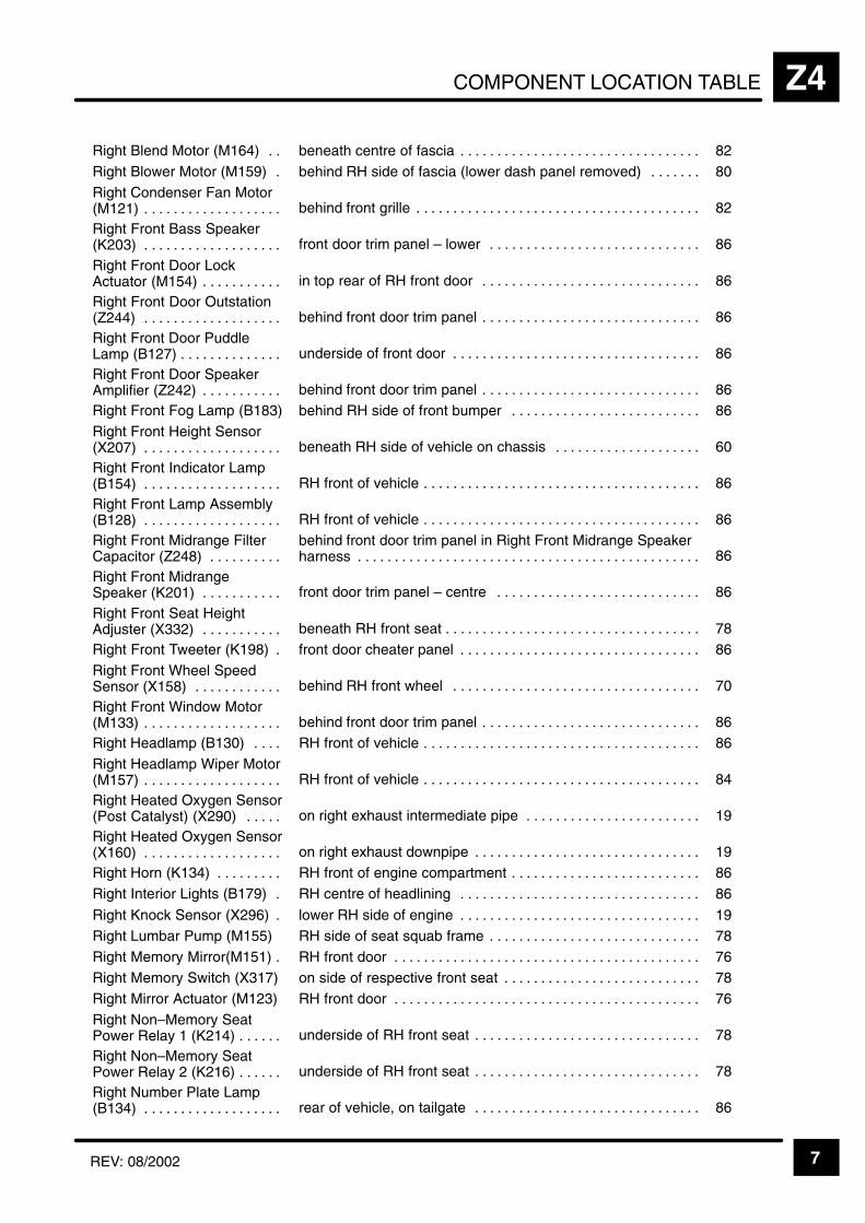
COMPONENT LOCATION TABLE Z4
7REV: 08/2002
ÁÁÁÁÁÁÁÁÁÁÁÁÁÁÁÁÁÁÁÁÁÁ
Right Blend Motor (M164) . . ÁÁÁÁÁÁÁÁÁÁÁÁÁÁÁÁÁÁÁÁÁÁÁÁÁÁÁÁÁÁÁÁÁÁÁÁÁÁ
beneath centre of fascia . . . . . . . . . . . . . . . . . . . . . . . . . . . . . . . . . ÁÁÁÁÁÁÁÁÁÁÁÁÁÁÁÁ
82
ÁÁÁÁÁÁÁÁÁÁÁÁÁÁÁÁÁÁÁÁÁÁ
Right Blower Motor (M159) . ÁÁÁÁÁÁÁÁÁÁÁÁÁÁÁÁÁÁÁÁÁÁÁÁÁÁÁÁÁÁÁÁÁÁÁÁÁÁ
behind RH side of fascia (lower dash panel removed) . . . . . . . ÁÁÁÁÁÁÁÁÁÁÁÁÁÁÁÁ
80
ÁÁÁÁÁÁÁÁÁÁÁÁÁÁÁÁÁÁÁÁÁÁ
Right Condenser Fan Motor(M121) . . . . . . . . . . . . . . . . . . .
ÁÁÁÁÁÁÁÁÁÁÁÁÁÁÁÁÁÁÁÁÁÁÁÁÁÁÁÁÁÁÁÁÁÁÁÁÁÁbehind front grille . . . . . . . . . . . . . . . . . . . . . . . . . . . . . . . . . . . . . . .
ÁÁÁÁÁÁÁÁÁÁÁÁÁÁÁÁ82ÁÁÁÁÁÁÁÁÁÁÁ
ÁÁÁÁÁÁÁÁÁÁÁÁÁÁÁÁÁÁÁÁÁÁ
Right Front Bass Speaker(K203) . . . . . . . . . . . . . . . . . . .
ÁÁÁÁÁÁÁÁÁÁÁÁÁÁÁÁÁÁÁÁÁÁÁÁÁÁÁÁÁÁÁÁÁÁÁÁÁÁÁÁÁÁÁÁÁÁÁÁÁÁÁÁÁÁÁÁÁ
front door trim panel – lower . . . . . . . . . . . . . . . . . . . . . . . . . . . . .
ÁÁÁÁÁÁÁÁÁÁÁÁÁÁÁÁÁÁÁÁÁÁÁÁ
86ÁÁÁÁÁÁÁÁÁÁÁÁÁÁÁÁÁÁÁÁÁÁÁÁÁÁÁÁÁÁÁÁÁ
Right Front Door LockActuator (M154) . . . . . . . . . . .
ÁÁÁÁÁÁÁÁÁÁÁÁÁÁÁÁÁÁÁÁÁÁÁÁÁÁÁÁÁÁÁÁÁÁÁÁÁÁÁÁÁÁÁÁÁÁÁÁÁÁÁÁÁÁÁÁÁ
in top rear of RH front door . . . . . . . . . . . . . . . . . . . . . . . . . . . . . . ÁÁÁÁÁÁÁÁÁÁÁÁÁÁÁÁÁÁÁÁÁÁÁÁ
86
ÁÁÁÁÁÁÁÁÁÁÁÁÁÁÁÁÁÁÁÁÁÁ
Right Front Door Outstation(Z244) . . . . . . . . . . . . . . . . . . .
ÁÁÁÁÁÁÁÁÁÁÁÁÁÁÁÁÁÁÁÁÁÁÁÁÁÁÁÁÁÁÁÁÁÁÁÁÁÁ
behind front door trim panel . . . . . . . . . . . . . . . . . . . . . . . . . . . . . . ÁÁÁÁÁÁÁÁÁÁÁÁÁÁÁÁ
86ÁÁÁÁÁÁÁÁÁÁÁÁÁÁÁÁÁÁÁÁÁÁÁÁÁÁÁÁÁÁÁÁÁ
Right Front Door PuddleLamp (B127) . . . . . . . . . . . . . .
ÁÁÁÁÁÁÁÁÁÁÁÁÁÁÁÁÁÁÁÁÁÁÁÁÁÁÁÁÁÁÁÁÁÁÁÁÁÁÁÁÁÁÁÁÁÁÁÁÁÁÁÁÁÁÁÁÁ
underside of front door . . . . . . . . . . . . . . . . . . . . . . . . . . . . . . . . . .
ÁÁÁÁÁÁÁÁÁÁÁÁÁÁÁÁÁÁÁÁÁÁÁÁ
86
ÁÁÁÁÁÁÁÁÁÁÁÁÁÁÁÁÁÁÁÁÁÁ
Right Front Door SpeakerAmplifier (Z242) . . . . . . . . . . .
ÁÁÁÁÁÁÁÁÁÁÁÁÁÁÁÁÁÁÁÁÁÁÁÁÁÁÁÁÁÁÁÁÁÁÁÁÁÁbehind front door trim panel . . . . . . . . . . . . . . . . . . . . . . . . . . . . . .
ÁÁÁÁÁÁÁÁÁÁÁÁÁÁÁÁ86ÁÁÁÁÁÁÁÁÁÁÁ
ÁÁÁÁÁÁÁÁÁÁÁRight Front Fog Lamp (B183)ÁÁÁÁÁÁÁÁÁÁÁÁÁÁÁÁÁÁÁÁÁÁÁÁÁÁÁÁÁÁÁÁÁÁÁÁÁÁbehind RH side of front bumper . . . . . . . . . . . . . . . . . . . . . . . . . .
ÁÁÁÁÁÁÁÁÁÁÁÁÁÁÁÁ86ÁÁÁÁÁÁÁÁÁÁÁ
ÁÁÁÁÁÁÁÁÁÁÁÁÁÁÁÁÁÁÁÁÁÁ
Right Front Height Sensor(X207) . . . . . . . . . . . . . . . . . . .
ÁÁÁÁÁÁÁÁÁÁÁÁÁÁÁÁÁÁÁÁÁÁÁÁÁÁÁÁÁÁÁÁÁÁÁÁÁÁÁÁÁÁÁÁÁÁÁÁÁÁÁÁÁÁÁÁÁ
beneath RH side of vehicle on chassis . . . . . . . . . . . . . . . . . . . .
ÁÁÁÁÁÁÁÁÁÁÁÁÁÁÁÁÁÁÁÁÁÁÁÁ
60ÁÁÁÁÁÁÁÁÁÁÁÁÁÁÁÁÁÁÁÁÁÁÁÁÁÁÁÁÁÁÁÁÁ
Right Front Indicator Lamp(B154) . . . . . . . . . . . . . . . . . . .
ÁÁÁÁÁÁÁÁÁÁÁÁÁÁÁÁÁÁÁÁÁÁÁÁÁÁÁÁÁÁÁÁÁÁÁÁÁÁÁÁÁÁÁÁÁÁÁÁÁÁÁÁÁÁÁÁÁ
RH front of vehicle . . . . . . . . . . . . . . . . . . . . . . . . . . . . . . . . . . . . . . ÁÁÁÁÁÁÁÁÁÁÁÁÁÁÁÁÁÁÁÁÁÁÁÁ
86
ÁÁÁÁÁÁÁÁÁÁÁÁÁÁÁÁÁÁÁÁÁÁ
Right Front Lamp Assembly(B128) . . . . . . . . . . . . . . . . . . .
ÁÁÁÁÁÁÁÁÁÁÁÁÁÁÁÁÁÁÁÁÁÁÁÁÁÁÁÁÁÁÁÁÁÁÁÁÁÁ
RH front of vehicle . . . . . . . . . . . . . . . . . . . . . . . . . . . . . . . . . . . . . . ÁÁÁÁÁÁÁÁÁÁÁÁÁÁÁÁ
86ÁÁÁÁÁÁÁÁÁÁÁÁÁÁÁÁÁÁÁÁÁÁÁÁÁÁÁÁÁÁÁÁÁ
Right Front Midrange FilterCapacitor (Z248) . . . . . . . . . .
ÁÁÁÁÁÁÁÁÁÁÁÁÁÁÁÁÁÁÁÁÁÁÁÁÁÁÁÁÁÁÁÁÁÁÁÁÁÁÁÁÁÁÁÁÁÁÁÁÁÁÁÁÁÁÁÁÁ
behind front door trim panel in Right Front Midrange Speakerharness . . . . . . . . . . . . . . . . . . . . . . . . . . . . . . . . . . . . . . . . . . . . . . .
ÁÁÁÁÁÁÁÁÁÁÁÁÁÁÁÁÁÁÁÁÁÁÁÁ
86ÁÁÁÁÁÁÁÁÁÁÁÁÁÁÁÁÁÁÁÁÁÁ
Right Front MidrangeSpeaker (K201) . . . . . . . . . . .
ÁÁÁÁÁÁÁÁÁÁÁÁÁÁÁÁÁÁÁÁÁÁÁÁÁÁÁÁÁÁÁÁÁÁÁÁÁÁfront door trim panel – centre . . . . . . . . . . . . . . . . . . . . . . . . . . . .
ÁÁÁÁÁÁÁÁÁÁÁÁÁÁÁÁ86ÁÁÁÁÁÁÁÁÁÁÁ
ÁÁÁÁÁÁÁÁÁÁÁÁÁÁÁÁÁÁÁÁÁÁ
Right Front Seat HeightAdjuster (X332) . . . . . . . . . . .
ÁÁÁÁÁÁÁÁÁÁÁÁÁÁÁÁÁÁÁÁÁÁÁÁÁÁÁÁÁÁÁÁÁÁÁÁÁÁÁÁÁÁÁÁÁÁÁÁÁÁÁÁÁÁÁÁÁ
beneath RH front seat . . . . . . . . . . . . . . . . . . . . . . . . . . . . . . . . . . .
ÁÁÁÁÁÁÁÁÁÁÁÁÁÁÁÁÁÁÁÁÁÁÁÁ
78ÁÁÁÁÁÁÁÁÁÁÁÁÁÁÁÁÁÁÁÁÁÁ
Right Front Tweeter (K198) . ÁÁÁÁÁÁÁÁÁÁÁÁÁÁÁÁÁÁÁÁÁÁÁÁÁÁÁÁÁÁÁÁÁÁÁÁÁÁ
front door cheater panel . . . . . . . . . . . . . . . . . . . . . . . . . . . . . . . . . ÁÁÁÁÁÁÁÁÁÁÁÁÁÁÁÁ
86ÁÁÁÁÁÁÁÁÁÁÁÁÁÁÁÁÁÁÁÁÁÁÁÁÁÁÁÁÁÁÁÁÁ
Right Front Wheel SpeedSensor (X158) . . . . . . . . . . . .
ÁÁÁÁÁÁÁÁÁÁÁÁÁÁÁÁÁÁÁÁÁÁÁÁÁÁÁÁÁÁÁÁÁÁÁÁÁÁÁÁÁÁÁÁÁÁÁÁÁÁÁÁÁÁÁÁÁ
behind RH front wheel . . . . . . . . . . . . . . . . . . . . . . . . . . . . . . . . . . ÁÁÁÁÁÁÁÁÁÁÁÁÁÁÁÁÁÁÁÁÁÁÁÁ
70
ÁÁÁÁÁÁÁÁÁÁÁÁÁÁÁÁÁÁÁÁÁÁ
Right Front Window Motor(M133) . . . . . . . . . . . . . . . . . . .
ÁÁÁÁÁÁÁÁÁÁÁÁÁÁÁÁÁÁÁÁÁÁÁÁÁÁÁÁÁÁÁÁÁÁÁÁÁÁbehind front door trim panel . . . . . . . . . . . . . . . . . . . . . . . . . . . . . .
ÁÁÁÁÁÁÁÁÁÁÁÁÁÁÁÁ86ÁÁÁÁÁÁÁÁÁÁÁ
ÁÁÁÁÁÁÁÁÁÁÁRight Headlamp (B130) . . . .
ÁÁÁÁÁÁÁÁÁÁÁÁÁÁÁÁÁÁÁÁÁÁÁÁÁÁÁÁÁÁÁÁÁÁÁÁÁÁ
RH front of vehicle . . . . . . . . . . . . . . . . . . . . . . . . . . . . . . . . . . . . . . ÁÁÁÁÁÁÁÁÁÁÁÁÁÁÁÁ
86ÁÁÁÁÁÁÁÁÁÁÁÁÁÁÁÁÁÁÁÁÁÁÁÁÁÁÁÁÁÁÁÁÁ
Right Headlamp Wiper Motor(M157) . . . . . . . . . . . . . . . . . . .
ÁÁÁÁÁÁÁÁÁÁÁÁÁÁÁÁÁÁÁÁÁÁÁÁÁÁÁÁÁÁÁÁÁÁÁÁÁÁÁÁÁÁÁÁÁÁÁÁÁÁÁÁÁÁÁÁÁ
RH front of vehicle . . . . . . . . . . . . . . . . . . . . . . . . . . . . . . . . . . . . . .
ÁÁÁÁÁÁÁÁÁÁÁÁÁÁÁÁÁÁÁÁÁÁÁÁ
84ÁÁÁÁÁÁÁÁÁÁÁÁÁÁÁÁÁÁÁÁÁÁ
Right Heated Oxygen Sensor(Post Catalyst) (X290) . . . . .
ÁÁÁÁÁÁÁÁÁÁÁÁÁÁÁÁÁÁÁÁÁÁÁÁÁÁÁÁÁÁÁÁÁÁÁÁÁÁon right exhaust intermediate pipe . . . . . . . . . . . . . . . . . . . . . . . .
ÁÁÁÁÁÁÁÁÁÁÁÁÁÁÁÁ19ÁÁÁÁÁÁÁÁÁÁÁ
ÁÁÁÁÁÁÁÁÁÁÁÁÁÁÁÁÁÁÁÁÁÁ
Right Heated Oxygen Sensor(X160) . . . . . . . . . . . . . . . . . . .
ÁÁÁÁÁÁÁÁÁÁÁÁÁÁÁÁÁÁÁÁÁÁÁÁÁÁÁÁÁÁÁÁÁÁÁÁÁÁÁÁÁÁÁÁÁÁÁÁÁÁÁÁÁÁÁÁÁ
on right exhaust downpipe . . . . . . . . . . . . . . . . . . . . . . . . . . . . . . .
ÁÁÁÁÁÁÁÁÁÁÁÁÁÁÁÁÁÁÁÁÁÁÁÁ
19ÁÁÁÁÁÁÁÁÁÁÁÁÁÁÁÁÁÁÁÁÁÁ
Right Horn (K134) . . . . . . . . . ÁÁÁÁÁÁÁÁÁÁÁÁÁÁÁÁÁÁÁÁÁÁÁÁÁÁÁÁÁÁÁÁÁÁÁÁÁÁ
RH front of engine compartment . . . . . . . . . . . . . . . . . . . . . . . . . . ÁÁÁÁÁÁÁÁÁÁÁÁÁÁÁÁ
86ÁÁÁÁÁÁÁÁÁÁÁÁÁÁÁÁÁÁÁÁÁÁ
Right Interior Lights (B179) . ÁÁÁÁÁÁÁÁÁÁÁÁÁÁÁÁÁÁÁÁÁÁÁÁÁÁÁÁÁÁÁÁÁÁÁÁÁÁ
RH centre of headlining . . . . . . . . . . . . . . . . . . . . . . . . . . . . . . . . . ÁÁÁÁÁÁÁÁÁÁÁÁÁÁÁÁ
86ÁÁÁÁÁÁÁÁÁÁÁÁÁÁÁÁÁÁÁÁÁÁ
Right Knock Sensor (X296) . ÁÁÁÁÁÁÁÁÁÁÁÁÁÁÁÁÁÁÁÁÁÁÁÁÁÁÁÁÁÁÁÁÁÁÁÁÁÁ
lower RH side of engine . . . . . . . . . . . . . . . . . . . . . . . . . . . . . . . . . ÁÁÁÁÁÁÁÁÁÁÁÁÁÁÁÁ
19ÁÁÁÁÁÁÁÁÁÁÁÁÁÁÁÁÁÁÁÁÁÁ
Right Lumbar Pump (M155) ÁÁÁÁÁÁÁÁÁÁÁÁÁÁÁÁÁÁÁÁÁÁÁÁÁÁÁÁÁÁÁÁÁÁÁÁÁÁ
RH side of seat squab frame . . . . . . . . . . . . . . . . . . . . . . . . . . . . . ÁÁÁÁÁÁÁÁÁÁÁÁÁÁÁÁ
78ÁÁÁÁÁÁÁÁÁÁÁÁÁÁÁÁÁÁÁÁÁÁ
Right Memory Mirror(M151) . ÁÁÁÁÁÁÁÁÁÁÁÁÁÁÁÁÁÁÁÁÁÁÁÁÁÁÁÁÁÁÁÁÁÁÁÁÁÁ
RH front door . . . . . . . . . . . . . . . . . . . . . . . . . . . . . . . . . . . . . . . . . . ÁÁÁÁÁÁÁÁÁÁÁÁÁÁÁÁ
76ÁÁÁÁÁÁÁÁÁÁÁÁÁÁÁÁÁÁÁÁÁÁ
Right Memory Switch (X317) ÁÁÁÁÁÁÁÁÁÁÁÁÁÁÁÁÁÁÁÁÁÁÁÁÁÁÁÁÁÁÁÁÁÁÁÁÁÁ
on side of respective front seat . . . . . . . . . . . . . . . . . . . . . . . . . . . ÁÁÁÁÁÁÁÁÁÁÁÁÁÁÁÁ
78
ÁÁÁÁÁÁÁÁÁÁÁÁÁÁÁÁÁÁÁÁÁÁ
Right Mirror Actuator (M123) ÁÁÁÁÁÁÁÁÁÁÁÁÁÁÁÁÁÁÁÁÁÁÁÁÁÁÁÁÁÁÁÁÁÁÁÁÁÁ
RH front door . . . . . . . . . . . . . . . . . . . . . . . . . . . . . . . . . . . . . . . . . . ÁÁÁÁÁÁÁÁÁÁÁÁÁÁÁÁ
76
ÁÁÁÁÁÁÁÁÁÁÁÁÁÁÁÁÁÁÁÁÁÁ
Right Non–Memory SeatPower Relay 1 (K214) . . . . . .
ÁÁÁÁÁÁÁÁÁÁÁÁÁÁÁÁÁÁÁÁÁÁÁÁÁÁÁÁÁÁÁÁÁÁÁÁÁÁunderside of RH front seat . . . . . . . . . . . . . . . . . . . . . . . . . . . . . . .
ÁÁÁÁÁÁÁÁÁÁÁÁÁÁÁÁ78ÁÁÁÁÁÁÁÁÁÁÁ
ÁÁÁÁÁÁÁÁÁÁÁÁÁÁÁÁÁÁÁÁÁÁ
Right Non–Memory SeatPower Relay 2 (K216) . . . . . .
ÁÁÁÁÁÁÁÁÁÁÁÁÁÁÁÁÁÁÁÁÁÁÁÁÁÁÁÁÁÁÁÁÁÁÁÁÁÁÁÁÁÁÁÁÁÁÁÁÁÁÁÁÁÁÁÁÁ
underside of RH front seat . . . . . . . . . . . . . . . . . . . . . . . . . . . . . . .
ÁÁÁÁÁÁÁÁÁÁÁÁÁÁÁÁÁÁÁÁÁÁÁÁ
78ÁÁÁÁÁÁÁÁÁÁÁÁÁÁÁÁÁÁÁÁÁÁÁÁÁÁÁÁÁÁÁÁÁ
Right Number Plate Lamp(B134) . . . . . . . . . . . . . . . . . . .
ÁÁÁÁÁÁÁÁÁÁÁÁÁÁÁÁÁÁÁÁÁÁÁÁÁÁÁÁÁÁÁÁÁÁÁÁÁÁÁÁÁÁÁÁÁÁÁÁÁÁÁÁÁÁÁÁÁ
rear of vehicle, on tailgate . . . . . . . . . . . . . . . . . . . . . . . . . . . . . . . ÁÁÁÁÁÁÁÁÁÁÁÁÁÁÁÁÁÁÁÁÁÁÁÁ
86
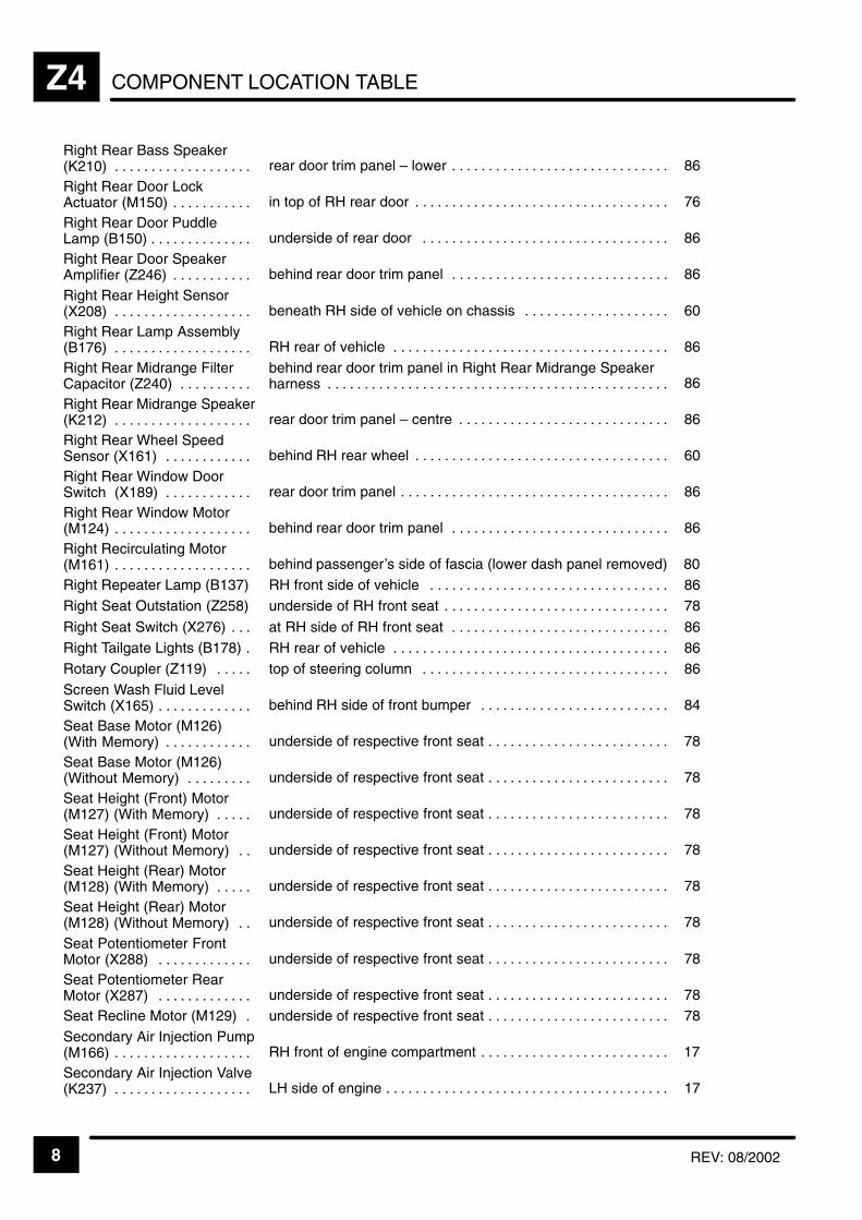
COMPONENT LOCATION TABLEZ4
8 REV: 08/2002
ÁÁÁÁÁÁÁÁÁÁÁÁÁÁÁÁÁÁÁÁ
Right Rear Bass Speaker(K210) . . . . . . . . . . . . . . . . . . .
ÁÁÁÁÁÁÁÁÁÁÁÁÁÁÁÁÁÁÁÁÁÁÁÁÁÁÁÁÁÁÁÁÁÁÁÁÁÁÁÁrear door trim panel – lower . . . . . . . . . . . . . . . . . . . . . . . . . . . . . .
ÁÁÁÁÁÁÁÁÁÁÁÁÁÁ86ÁÁÁÁÁÁÁÁÁÁ
ÁÁÁÁÁÁÁÁÁÁÁÁÁÁÁÁÁÁÁÁ
Right Rear Door LockActuator (M150) . . . . . . . . . . .
ÁÁÁÁÁÁÁÁÁÁÁÁÁÁÁÁÁÁÁÁÁÁÁÁÁÁÁÁÁÁÁÁÁÁÁÁÁÁÁÁÁÁÁÁÁÁÁÁÁÁÁÁÁÁÁÁÁÁÁÁ
in top of RH rear door . . . . . . . . . . . . . . . . . . . . . . . . . . . . . . . . . . .
ÁÁÁÁÁÁÁÁÁÁÁÁÁÁÁÁÁÁÁÁÁ
76ÁÁÁÁÁÁÁÁÁÁÁÁÁÁÁÁÁÁÁÁÁÁÁÁÁÁÁÁÁÁ
Right Rear Door PuddleLamp (B150) . . . . . . . . . . . . . .
ÁÁÁÁÁÁÁÁÁÁÁÁÁÁÁÁÁÁÁÁÁÁÁÁÁÁÁÁÁÁÁÁÁÁÁÁÁÁÁÁÁÁÁÁÁÁÁÁÁÁÁÁÁÁÁÁÁÁÁÁ
underside of rear door . . . . . . . . . . . . . . . . . . . . . . . . . . . . . . . . . . ÁÁÁÁÁÁÁÁÁÁÁÁÁÁÁÁÁÁÁÁÁ
86
ÁÁÁÁÁÁÁÁÁÁÁÁÁÁÁÁÁÁÁÁ
Right Rear Door SpeakerAmplifier (Z246) . . . . . . . . . . .
ÁÁÁÁÁÁÁÁÁÁÁÁÁÁÁÁÁÁÁÁÁÁÁÁÁÁÁÁÁÁÁÁÁÁÁÁÁÁÁÁbehind rear door trim panel . . . . . . . . . . . . . . . . . . . . . . . . . . . . . .
ÁÁÁÁÁÁÁÁÁÁÁÁÁÁ86ÁÁÁÁÁÁÁÁÁÁ
ÁÁÁÁÁÁÁÁÁÁÁÁÁÁÁÁÁÁÁÁ
Right Rear Height Sensor(X208) . . . . . . . . . . . . . . . . . . .
ÁÁÁÁÁÁÁÁÁÁÁÁÁÁÁÁÁÁÁÁÁÁÁÁÁÁÁÁÁÁÁÁÁÁÁÁÁÁÁÁÁÁÁÁÁÁÁÁÁÁÁÁÁÁÁÁÁÁÁÁ
beneath RH side of vehicle on chassis . . . . . . . . . . . . . . . . . . . .
ÁÁÁÁÁÁÁÁÁÁÁÁÁÁÁÁÁÁÁÁÁ
60ÁÁÁÁÁÁÁÁÁÁÁÁÁÁÁÁÁÁÁÁÁÁÁÁÁÁÁÁÁÁ
Right Rear Lamp Assembly(B176) . . . . . . . . . . . . . . . . . . .
ÁÁÁÁÁÁÁÁÁÁÁÁÁÁÁÁÁÁÁÁÁÁÁÁÁÁÁÁÁÁÁÁÁÁÁÁÁÁÁÁÁÁÁÁÁÁÁÁÁÁÁÁÁÁÁÁÁÁÁÁ
RH rear of vehicle . . . . . . . . . . . . . . . . . . . . . . . . . . . . . . . . . . . . . . ÁÁÁÁÁÁÁÁÁÁÁÁÁÁÁÁÁÁÁÁÁ
86
ÁÁÁÁÁÁÁÁÁÁÁÁÁÁÁÁÁÁÁÁ
Right Rear Midrange FilterCapacitor (Z240) . . . . . . . . . .
ÁÁÁÁÁÁÁÁÁÁÁÁÁÁÁÁÁÁÁÁÁÁÁÁÁÁÁÁÁÁÁÁÁÁÁÁÁÁÁÁ
behind rear door trim panel in Right Rear Midrange Speakerharness . . . . . . . . . . . . . . . . . . . . . . . . . . . . . . . . . . . . . . . . . . . . . . .
ÁÁÁÁÁÁÁÁÁÁÁÁÁÁ
86ÁÁÁÁÁÁÁÁÁÁÁÁÁÁÁÁÁÁÁÁÁÁÁÁÁÁÁÁÁÁ
Right Rear Midrange Speaker(K212) . . . . . . . . . . . . . . . . . . .
ÁÁÁÁÁÁÁÁÁÁÁÁÁÁÁÁÁÁÁÁÁÁÁÁÁÁÁÁÁÁÁÁÁÁÁÁÁÁÁÁÁÁÁÁÁÁÁÁÁÁÁÁÁÁÁÁÁÁÁÁ
rear door trim panel – centre . . . . . . . . . . . . . . . . . . . . . . . . . . . . .
ÁÁÁÁÁÁÁÁÁÁÁÁÁÁÁÁÁÁÁÁÁ
86
ÁÁÁÁÁÁÁÁÁÁÁÁÁÁÁÁÁÁÁÁ
Right Rear Wheel SpeedSensor (X161) . . . . . . . . . . . .
ÁÁÁÁÁÁÁÁÁÁÁÁÁÁÁÁÁÁÁÁÁÁÁÁÁÁÁÁÁÁÁÁÁÁÁÁÁÁÁÁbehind RH rear wheel . . . . . . . . . . . . . . . . . . . . . . . . . . . . . . . . . . .
ÁÁÁÁÁÁÁÁÁÁÁÁÁÁ60ÁÁÁÁÁÁÁÁÁÁ
ÁÁÁÁÁÁÁÁÁÁÁÁÁÁÁÁÁÁÁÁ
Right Rear Window DoorSwitch (X189) . . . . . . . . . . . .
ÁÁÁÁÁÁÁÁÁÁÁÁÁÁÁÁÁÁÁÁÁÁÁÁÁÁÁÁÁÁÁÁÁÁÁÁÁÁÁÁÁÁÁÁÁÁÁÁÁÁÁÁÁÁÁÁÁÁÁÁ
rear door trim panel . . . . . . . . . . . . . . . . . . . . . . . . . . . . . . . . . . . . .
ÁÁÁÁÁÁÁÁÁÁÁÁÁÁÁÁÁÁÁÁÁ
86ÁÁÁÁÁÁÁÁÁÁÁÁÁÁÁÁÁÁÁÁÁÁÁÁÁÁÁÁÁÁ
Right Rear Window Motor(M124) . . . . . . . . . . . . . . . . . . .
ÁÁÁÁÁÁÁÁÁÁÁÁÁÁÁÁÁÁÁÁÁÁÁÁÁÁÁÁÁÁÁÁÁÁÁÁÁÁÁÁÁÁÁÁÁÁÁÁÁÁÁÁÁÁÁÁÁÁÁÁ
behind rear door trim panel . . . . . . . . . . . . . . . . . . . . . . . . . . . . . . ÁÁÁÁÁÁÁÁÁÁÁÁÁÁÁÁÁÁÁÁÁ
86
ÁÁÁÁÁÁÁÁÁÁÁÁÁÁÁÁÁÁÁÁ
Right Recirculating Motor(M161) . . . . . . . . . . . . . . . . . . .
ÁÁÁÁÁÁÁÁÁÁÁÁÁÁÁÁÁÁÁÁÁÁÁÁÁÁÁÁÁÁÁÁÁÁÁÁÁÁÁÁbehind passenger’s side of fascia (lower dash panel removed)
ÁÁÁÁÁÁÁÁÁÁÁÁÁÁ 80ÁÁÁÁÁÁÁÁÁÁ
ÁÁÁÁÁÁÁÁÁÁRight Repeater Lamp (B137)
ÁÁÁÁÁÁÁÁÁÁÁÁÁÁÁÁÁÁÁÁÁÁÁÁÁÁÁÁÁÁÁÁÁÁÁÁÁÁÁÁ
RH front side of vehicle . . . . . . . . . . . . . . . . . . . . . . . . . . . . . . . . . ÁÁÁÁÁÁÁÁÁÁÁÁÁÁ
86ÁÁÁÁÁÁÁÁÁÁÁÁÁÁÁÁÁÁÁÁ
Right Seat Outstation (Z258)ÁÁÁÁÁÁÁÁÁÁÁÁÁÁÁÁÁÁÁÁÁÁÁÁÁÁÁÁÁÁÁÁÁÁÁÁÁÁÁÁ
underside of RH front seat . . . . . . . . . . . . . . . . . . . . . . . . . . . . . . . ÁÁÁÁÁÁÁÁÁÁÁÁÁÁ
78ÁÁÁÁÁÁÁÁÁÁÁÁÁÁÁÁÁÁÁÁ
Right Seat Switch (X276) . . . ÁÁÁÁÁÁÁÁÁÁÁÁÁÁÁÁÁÁÁÁÁÁÁÁÁÁÁÁÁÁÁÁÁÁÁÁÁÁÁÁ
at RH side of RH front seat . . . . . . . . . . . . . . . . . . . . . . . . . . . . . . ÁÁÁÁÁÁÁÁÁÁÁÁÁÁ
86ÁÁÁÁÁÁÁÁÁÁÁÁÁÁÁÁÁÁÁÁ
Right Tailgate Lights (B178) . ÁÁÁÁÁÁÁÁÁÁÁÁÁÁÁÁÁÁÁÁÁÁÁÁÁÁÁÁÁÁÁÁÁÁÁÁÁÁÁÁ
RH rear of vehicle . . . . . . . . . . . . . . . . . . . . . . . . . . . . . . . . . . . . . . ÁÁÁÁÁÁÁÁÁÁÁÁÁÁ
86ÁÁÁÁÁÁÁÁÁÁÁÁÁÁÁÁÁÁÁÁ
Rotary Coupler (Z119) . . . . . ÁÁÁÁÁÁÁÁÁÁÁÁÁÁÁÁÁÁÁÁÁÁÁÁÁÁÁÁÁÁÁÁÁÁÁÁÁÁÁÁ
top of steering column . . . . . . . . . . . . . . . . . . . . . . . . . . . . . . . . . . ÁÁÁÁÁÁÁÁÁÁÁÁÁÁ
86ÁÁÁÁÁÁÁÁÁÁÁÁÁÁÁÁÁÁÁÁÁÁÁÁÁÁÁÁÁÁ
Screen Wash Fluid LevelSwitch (X165) . . . . . . . . . . . . .
ÁÁÁÁÁÁÁÁÁÁÁÁÁÁÁÁÁÁÁÁÁÁÁÁÁÁÁÁÁÁÁÁÁÁÁÁÁÁÁÁÁÁÁÁÁÁÁÁÁÁÁÁÁÁÁÁÁÁÁÁ
behind RH side of front bumper . . . . . . . . . . . . . . . . . . . . . . . . . . ÁÁÁÁÁÁÁÁÁÁÁÁÁÁÁÁÁÁÁÁÁ
84
ÁÁÁÁÁÁÁÁÁÁÁÁÁÁÁÁÁÁÁÁ
Seat Base Motor (M126)(With Memory) . . . . . . . . . . . .
ÁÁÁÁÁÁÁÁÁÁÁÁÁÁÁÁÁÁÁÁÁÁÁÁÁÁÁÁÁÁÁÁÁÁÁÁÁÁÁÁ
underside of respective front seat . . . . . . . . . . . . . . . . . . . . . . . . . ÁÁÁÁÁÁÁÁÁÁÁÁÁÁ
78ÁÁÁÁÁÁÁÁÁÁÁÁÁÁÁÁÁÁÁÁÁÁÁÁÁÁÁÁÁÁ
Seat Base Motor (M126)(Without Memory) . . . . . . . . .
ÁÁÁÁÁÁÁÁÁÁÁÁÁÁÁÁÁÁÁÁÁÁÁÁÁÁÁÁÁÁÁÁÁÁÁÁÁÁÁÁÁÁÁÁÁÁÁÁÁÁÁÁÁÁÁÁÁÁÁÁ
underside of respective front seat . . . . . . . . . . . . . . . . . . . . . . . . .
ÁÁÁÁÁÁÁÁÁÁÁÁÁÁÁÁÁÁÁÁÁ
78ÁÁÁÁÁÁÁÁÁÁÁÁÁÁÁÁÁÁÁÁ
Seat Height (Front) Motor(M127) (With Memory) . . . . .
ÁÁÁÁÁÁÁÁÁÁÁÁÁÁÁÁÁÁÁÁÁÁÁÁÁÁÁÁÁÁÁÁÁÁÁÁÁÁÁÁunderside of respective front seat . . . . . . . . . . . . . . . . . . . . . . . . .
ÁÁÁÁÁÁÁÁÁÁÁÁÁÁ78ÁÁÁÁÁÁÁÁÁÁ
ÁÁÁÁÁÁÁÁÁÁÁÁÁÁÁÁÁÁÁÁ
Seat Height (Front) Motor(M127) (Without Memory) . .
ÁÁÁÁÁÁÁÁÁÁÁÁÁÁÁÁÁÁÁÁÁÁÁÁÁÁÁÁÁÁÁÁÁÁÁÁÁÁÁÁÁÁÁÁÁÁÁÁÁÁÁÁÁÁÁÁÁÁÁÁ
underside of respective front seat . . . . . . . . . . . . . . . . . . . . . . . . .
ÁÁÁÁÁÁÁÁÁÁÁÁÁÁÁÁÁÁÁÁÁ
78ÁÁÁÁÁÁÁÁÁÁÁÁÁÁÁÁÁÁÁÁÁÁÁÁÁÁÁÁÁÁ
Seat Height (Rear) Motor(M128) (With Memory) . . . . .
ÁÁÁÁÁÁÁÁÁÁÁÁÁÁÁÁÁÁÁÁÁÁÁÁÁÁÁÁÁÁÁÁÁÁÁÁÁÁÁÁÁÁÁÁÁÁÁÁÁÁÁÁÁÁÁÁÁÁÁÁ
underside of respective front seat . . . . . . . . . . . . . . . . . . . . . . . . .
ÁÁÁÁÁÁÁÁÁÁÁÁÁÁÁÁÁÁÁÁÁ
78
ÁÁÁÁÁÁÁÁÁÁÁÁÁÁÁÁÁÁÁÁ
Seat Height (Rear) Motor(M128) (Without Memory) . .
ÁÁÁÁÁÁÁÁÁÁÁÁÁÁÁÁÁÁÁÁÁÁÁÁÁÁÁÁÁÁÁÁÁÁÁÁÁÁÁÁunderside of respective front seat . . . . . . . . . . . . . . . . . . . . . . . . .
ÁÁÁÁÁÁÁÁÁÁÁÁÁÁ78ÁÁÁÁÁÁÁÁÁÁ
ÁÁÁÁÁÁÁÁÁÁÁÁÁÁÁÁÁÁÁÁ
Seat Potentiometer FrontMotor (X288) . . . . . . . . . . . . .
ÁÁÁÁÁÁÁÁÁÁÁÁÁÁÁÁÁÁÁÁÁÁÁÁÁÁÁÁÁÁÁÁÁÁÁÁÁÁÁÁÁÁÁÁÁÁÁÁÁÁÁÁÁÁÁÁÁÁÁÁ
underside of respective front seat . . . . . . . . . . . . . . . . . . . . . . . . .
ÁÁÁÁÁÁÁÁÁÁÁÁÁÁÁÁÁÁÁÁÁ
78ÁÁÁÁÁÁÁÁÁÁÁÁÁÁÁÁÁÁÁÁÁÁÁÁÁÁÁÁÁÁ
Seat Potentiometer RearMotor (X287) . . . . . . . . . . . . .
ÁÁÁÁÁÁÁÁÁÁÁÁÁÁÁÁÁÁÁÁÁÁÁÁÁÁÁÁÁÁÁÁÁÁÁÁÁÁÁÁÁÁÁÁÁÁÁÁÁÁÁÁÁÁÁÁÁÁÁÁ
underside of respective front seat . . . . . . . . . . . . . . . . . . . . . . . . . ÁÁÁÁÁÁÁÁÁÁÁÁÁÁÁÁÁÁÁÁÁ
78
ÁÁÁÁÁÁÁÁÁÁÁÁÁÁÁÁÁÁÁÁ
Seat Recline Motor (M129) . ÁÁÁÁÁÁÁÁÁÁÁÁÁÁÁÁÁÁÁÁÁÁÁÁÁÁÁÁÁÁÁÁÁÁÁÁÁÁÁÁ
underside of respective front seat . . . . . . . . . . . . . . . . . . . . . . . . . ÁÁÁÁÁÁÁÁÁÁÁÁÁÁ
78
ÁÁÁÁÁÁÁÁÁÁÁÁÁÁÁÁÁÁÁÁ
Secondary Air Injection Pump(M166) . . . . . . . . . . . . . . . . . . .
ÁÁÁÁÁÁÁÁÁÁÁÁÁÁÁÁÁÁÁÁÁÁÁÁÁÁÁÁÁÁÁÁÁÁÁÁÁÁÁÁ
RH front of engine compartment . . . . . . . . . . . . . . . . . . . . . . . . . . ÁÁÁÁÁÁÁÁÁÁÁÁÁÁ
17ÁÁÁÁÁÁÁÁÁÁÁÁÁÁÁÁÁÁÁÁÁÁÁÁÁÁÁÁÁÁ
Secondary Air Injection Valve(K237) . . . . . . . . . . . . . . . . . . .
ÁÁÁÁÁÁÁÁÁÁÁÁÁÁÁÁÁÁÁÁÁÁÁÁÁÁÁÁÁÁÁÁÁÁÁÁÁÁÁÁÁÁÁÁÁÁÁÁÁÁÁÁÁÁÁÁÁÁÁÁ
LH side of engine . . . . . . . . . . . . . . . . . . . . . . . . . . . . . . . . . . . . . . .
ÁÁÁÁÁÁÁÁÁÁÁÁÁÁÁÁÁÁÁÁÁ
17
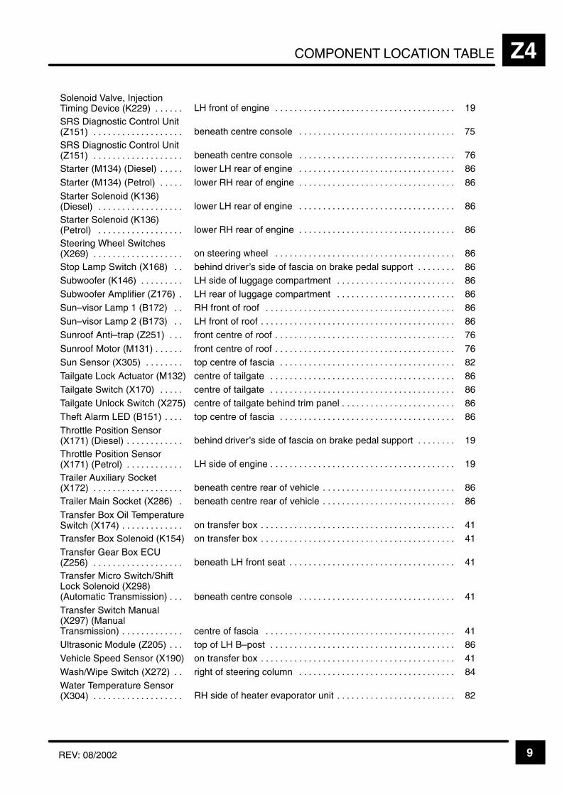
COMPONENT LOCATION TABLE Z4
9REV: 08/2002
ÁÁÁÁÁÁÁÁÁÁÁÁÁÁÁÁÁÁÁÁÁÁ
Solenoid Valve, InjectionTiming Device (K229) . . . . . .
ÁÁÁÁÁÁÁÁÁÁÁÁÁÁÁÁÁÁÁÁÁÁÁÁÁÁÁÁÁÁÁÁÁÁÁÁÁÁLH front of engine . . . . . . . . . . . . . . . . . . . . . . . . . . . . . . . . . . . . . .
ÁÁÁÁÁÁÁÁÁÁÁÁÁÁÁÁ19ÁÁÁÁÁÁÁÁÁÁÁ
ÁÁÁÁÁÁÁÁÁÁÁÁÁÁÁÁÁÁÁÁÁÁ
SRS Diagnostic Control Unit(Z151) . . . . . . . . . . . . . . . . . . .
ÁÁÁÁÁÁÁÁÁÁÁÁÁÁÁÁÁÁÁÁÁÁÁÁÁÁÁÁÁÁÁÁÁÁÁÁÁÁÁÁÁÁÁÁÁÁÁÁÁÁÁÁÁÁÁÁÁ
beneath centre console . . . . . . . . . . . . . . . . . . . . . . . . . . . . . . . . .
ÁÁÁÁÁÁÁÁÁÁÁÁÁÁÁÁÁÁÁÁÁÁÁÁ
75ÁÁÁÁÁÁÁÁÁÁÁÁÁÁÁÁÁÁÁÁÁÁÁÁÁÁÁÁÁÁÁÁÁ
SRS Diagnostic Control Unit(Z151) . . . . . . . . . . . . . . . . . . .
ÁÁÁÁÁÁÁÁÁÁÁÁÁÁÁÁÁÁÁÁÁÁÁÁÁÁÁÁÁÁÁÁÁÁÁÁÁÁÁÁÁÁÁÁÁÁÁÁÁÁÁÁÁÁÁÁÁ
beneath centre console . . . . . . . . . . . . . . . . . . . . . . . . . . . . . . . . . ÁÁÁÁÁÁÁÁÁÁÁÁÁÁÁÁÁÁÁÁÁÁÁÁ
76
ÁÁÁÁÁÁÁÁÁÁÁÁÁÁÁÁÁÁÁÁÁÁ
Starter (M134) (Diesel) . . . . . ÁÁÁÁÁÁÁÁÁÁÁÁÁÁÁÁÁÁÁÁÁÁÁÁÁÁÁÁÁÁÁÁÁÁÁÁÁÁ
lower LH rear of engine . . . . . . . . . . . . . . . . . . . . . . . . . . . . . . . . . ÁÁÁÁÁÁÁÁÁÁÁÁÁÁÁÁ
86
ÁÁÁÁÁÁÁÁÁÁÁÁÁÁÁÁÁÁÁÁÁÁ
Starter (M134) (Petrol) . . . . . ÁÁÁÁÁÁÁÁÁÁÁÁÁÁÁÁÁÁÁÁÁÁÁÁÁÁÁÁÁÁÁÁÁÁÁÁÁÁ
lower RH rear of engine . . . . . . . . . . . . . . . . . . . . . . . . . . . . . . . . . ÁÁÁÁÁÁÁÁÁÁÁÁÁÁÁÁ
86
ÁÁÁÁÁÁÁÁÁÁÁÁÁÁÁÁÁÁÁÁÁÁ
Starter Solenoid (K136)(Diesel) . . . . . . . . . . . . . . . . . .
ÁÁÁÁÁÁÁÁÁÁÁÁÁÁÁÁÁÁÁÁÁÁÁÁÁÁÁÁÁÁÁÁÁÁÁÁÁÁ
lower LH rear of engine . . . . . . . . . . . . . . . . . . . . . . . . . . . . . . . . . ÁÁÁÁÁÁÁÁÁÁÁÁÁÁÁÁ
86ÁÁÁÁÁÁÁÁÁÁÁÁÁÁÁÁÁÁÁÁÁÁÁÁÁÁÁÁÁÁÁÁÁ
Starter Solenoid (K136)(Petrol) . . . . . . . . . . . . . . . . . .
ÁÁÁÁÁÁÁÁÁÁÁÁÁÁÁÁÁÁÁÁÁÁÁÁÁÁÁÁÁÁÁÁÁÁÁÁÁÁÁÁÁÁÁÁÁÁÁÁÁÁÁÁÁÁÁÁÁ
lower RH rear of engine . . . . . . . . . . . . . . . . . . . . . . . . . . . . . . . . .
ÁÁÁÁÁÁÁÁÁÁÁÁÁÁÁÁÁÁÁÁÁÁÁÁ
86
ÁÁÁÁÁÁÁÁÁÁÁÁÁÁÁÁÁÁÁÁÁÁ
Steering Wheel Switches(X269) . . . . . . . . . . . . . . . . . . .
ÁÁÁÁÁÁÁÁÁÁÁÁÁÁÁÁÁÁÁÁÁÁÁÁÁÁÁÁÁÁÁÁÁÁÁÁÁÁon steering wheel . . . . . . . . . . . . . . . . . . . . . . . . . . . . . . . . . . . . . .
ÁÁÁÁÁÁÁÁÁÁÁÁÁÁÁÁ86ÁÁÁÁÁÁÁÁÁÁÁ
ÁÁÁÁÁÁÁÁÁÁÁStop Lamp Switch (X168) . . ÁÁÁÁÁÁÁÁÁÁÁÁÁÁÁÁÁÁÁÁÁÁÁÁÁÁÁÁÁÁÁÁÁÁÁÁÁÁbehind driver’s side of fascia on brake pedal support . . . . . . . .
ÁÁÁÁÁÁÁÁÁÁÁÁÁÁÁÁ86ÁÁÁÁÁÁÁÁÁÁÁ
ÁÁÁÁÁÁÁÁÁÁÁSubwoofer (K146) . . . . . . . . . ÁÁÁÁÁÁÁÁÁÁÁÁÁÁÁÁÁÁÁÁÁÁÁÁÁÁÁÁÁÁÁÁÁÁÁÁÁÁLH side of luggage compartment . . . . . . . . . . . . . . . . . . . . . . . . .
ÁÁÁÁÁÁÁÁÁÁÁÁÁÁÁÁ86ÁÁÁÁÁÁÁÁÁÁÁ
ÁÁÁÁÁÁÁÁÁÁÁSubwoofer Amplifier (Z176) .
ÁÁÁÁÁÁÁÁÁÁÁÁÁÁÁÁÁÁÁÁÁÁÁÁÁÁÁÁÁÁÁÁÁÁÁÁÁÁ
LH rear of luggage compartment . . . . . . . . . . . . . . . . . . . . . . . . . ÁÁÁÁÁÁÁÁÁÁÁÁÁÁÁÁ
86ÁÁÁÁÁÁÁÁÁÁÁÁÁÁÁÁÁÁÁÁÁÁ
Sun–visor Lamp 1 (B172) . . ÁÁÁÁÁÁÁÁÁÁÁÁÁÁÁÁÁÁÁÁÁÁÁÁÁÁÁÁÁÁÁÁÁÁÁÁÁÁ
RH front of roof . . . . . . . . . . . . . . . . . . . . . . . . . . . . . . . . . . . . . . . . ÁÁÁÁÁÁÁÁÁÁÁÁÁÁÁÁ
86ÁÁÁÁÁÁÁÁÁÁÁÁÁÁÁÁÁÁÁÁÁÁ
Sun–visor Lamp 2 (B173) . . ÁÁÁÁÁÁÁÁÁÁÁÁÁÁÁÁÁÁÁÁÁÁÁÁÁÁÁÁÁÁÁÁÁÁÁÁÁÁ
LH front of roof . . . . . . . . . . . . . . . . . . . . . . . . . . . . . . . . . . . . . . . . . ÁÁÁÁÁÁÁÁÁÁÁÁÁÁÁÁ
86ÁÁÁÁÁÁÁÁÁÁÁÁÁÁÁÁÁÁÁÁÁÁ
Sunroof Anti–trap (Z251) . . . ÁÁÁÁÁÁÁÁÁÁÁÁÁÁÁÁÁÁÁÁÁÁÁÁÁÁÁÁÁÁÁÁÁÁÁÁÁÁ
front centre of roof . . . . . . . . . . . . . . . . . . . . . . . . . . . . . . . . . . . . . . ÁÁÁÁÁÁÁÁÁÁÁÁÁÁÁÁ
76ÁÁÁÁÁÁÁÁÁÁÁÁÁÁÁÁÁÁÁÁÁÁ
Sunroof Motor (M131) . . . . . . ÁÁÁÁÁÁÁÁÁÁÁÁÁÁÁÁÁÁÁÁÁÁÁÁÁÁÁÁÁÁÁÁÁÁÁÁÁÁ
front centre of roof . . . . . . . . . . . . . . . . . . . . . . . . . . . . . . . . . . . . . . ÁÁÁÁÁÁÁÁÁÁÁÁÁÁÁÁ
76ÁÁÁÁÁÁÁÁÁÁÁÁÁÁÁÁÁÁÁÁÁÁ
Sun Sensor (X305) . . . . . . . . ÁÁÁÁÁÁÁÁÁÁÁÁÁÁÁÁÁÁÁÁÁÁÁÁÁÁÁÁÁÁÁÁÁÁÁÁÁÁ
top centre of fascia . . . . . . . . . . . . . . . . . . . . . . . . . . . . . . . . . . . . . ÁÁÁÁÁÁÁÁÁÁÁÁÁÁÁÁ
82ÁÁÁÁÁÁÁÁÁÁÁÁÁÁÁÁÁÁÁÁÁÁ
Tailgate Lock Actuator (M132)ÁÁÁÁÁÁÁÁÁÁÁÁÁÁÁÁÁÁÁÁÁÁÁÁÁÁÁÁÁÁÁÁÁÁÁÁÁÁ
centre of tailgate . . . . . . . . . . . . . . . . . . . . . . . . . . . . . . . . . . . . . . . ÁÁÁÁÁÁÁÁÁÁÁÁÁÁÁÁ
86ÁÁÁÁÁÁÁÁÁÁÁÁÁÁÁÁÁÁÁÁÁÁ
Tailgate Switch (X170) . . . . . ÁÁÁÁÁÁÁÁÁÁÁÁÁÁÁÁÁÁÁÁÁÁÁÁÁÁÁÁÁÁÁÁÁÁÁÁÁÁ
centre of tailgate . . . . . . . . . . . . . . . . . . . . . . . . . . . . . . . . . . . . . . . ÁÁÁÁÁÁÁÁÁÁÁÁÁÁÁÁ
86ÁÁÁÁÁÁÁÁÁÁÁÁÁÁÁÁÁÁÁÁÁÁ
Tailgate Unlock Switch (X275)ÁÁÁÁÁÁÁÁÁÁÁÁÁÁÁÁÁÁÁÁÁÁÁÁÁÁÁÁÁÁÁÁÁÁÁÁÁÁ
centre of tailgate behind trim panel . . . . . . . . . . . . . . . . . . . . . . . . ÁÁÁÁÁÁÁÁÁÁÁÁÁÁÁÁ
86
ÁÁÁÁÁÁÁÁÁÁÁÁÁÁÁÁÁÁÁÁÁÁ
Theft Alarm LED (B151) . . . . ÁÁÁÁÁÁÁÁÁÁÁÁÁÁÁÁÁÁÁÁÁÁÁÁÁÁÁÁÁÁÁÁÁÁÁÁÁÁ
top centre of fascia . . . . . . . . . . . . . . . . . . . . . . . . . . . . . . . . . . . . . ÁÁÁÁÁÁÁÁÁÁÁÁÁÁÁÁ
86
ÁÁÁÁÁÁÁÁÁÁÁÁÁÁÁÁÁÁÁÁÁÁ
Throttle Position Sensor(X171) (Diesel) . . . . . . . . . . . .
ÁÁÁÁÁÁÁÁÁÁÁÁÁÁÁÁÁÁÁÁÁÁÁÁÁÁÁÁÁÁÁÁÁÁÁÁÁÁbehind driver’s side of fascia on brake pedal support . . . . . . . .
ÁÁÁÁÁÁÁÁÁÁÁÁÁÁÁÁ19ÁÁÁÁÁÁÁÁÁÁÁ
ÁÁÁÁÁÁÁÁÁÁÁÁÁÁÁÁÁÁÁÁÁÁ
Throttle Position Sensor(X171) (Petrol) . . . . . . . . . . . .
ÁÁÁÁÁÁÁÁÁÁÁÁÁÁÁÁÁÁÁÁÁÁÁÁÁÁÁÁÁÁÁÁÁÁÁÁÁÁÁÁÁÁÁÁÁÁÁÁÁÁÁÁÁÁÁÁÁ
LH side of engine . . . . . . . . . . . . . . . . . . . . . . . . . . . . . . . . . . . . . . .
ÁÁÁÁÁÁÁÁÁÁÁÁÁÁÁÁÁÁÁÁÁÁÁÁ
19ÁÁÁÁÁÁÁÁÁÁÁÁÁÁÁÁÁÁÁÁÁÁÁÁÁÁÁÁÁÁÁÁÁ
Trailer Auxiliary Socket(X172) . . . . . . . . . . . . . . . . . . .
ÁÁÁÁÁÁÁÁÁÁÁÁÁÁÁÁÁÁÁÁÁÁÁÁÁÁÁÁÁÁÁÁÁÁÁÁÁÁÁÁÁÁÁÁÁÁÁÁÁÁÁÁÁÁÁÁÁ
beneath centre rear of vehicle . . . . . . . . . . . . . . . . . . . . . . . . . . . . ÁÁÁÁÁÁÁÁÁÁÁÁÁÁÁÁÁÁÁÁÁÁÁÁ
86
ÁÁÁÁÁÁÁÁÁÁÁTrailer Main Socket (X286) . ÁÁÁÁÁÁÁÁÁÁÁÁÁÁÁÁÁÁÁbeneath centre rear of vehicle . . . . . . . . . . . . . . . . . . . . . . . . . . . . ÁÁÁÁÁÁÁÁ86
ÁÁÁÁÁÁÁÁÁÁÁÁÁÁÁÁÁÁÁÁÁÁ
Transfer Box Oil TemperatureSwitch (X174) . . . . . . . . . . . . .
ÁÁÁÁÁÁÁÁÁÁÁÁÁÁÁÁÁÁÁÁÁÁÁÁÁÁÁÁÁÁÁÁÁÁÁÁÁÁ
on transfer box . . . . . . . . . . . . . . . . . . . . . . . . . . . . . . . . . . . . . . . . . ÁÁÁÁÁÁÁÁÁÁÁÁÁÁÁÁ
41ÁÁÁÁÁÁÁÁÁÁÁÁÁÁÁÁÁÁÁÁÁÁ
Transfer Box Solenoid (K154)ÁÁÁÁÁÁÁÁÁÁÁÁÁÁÁÁÁÁÁÁÁÁÁÁÁÁÁÁÁÁÁÁÁÁÁÁÁÁ
on transfer box . . . . . . . . . . . . . . . . . . . . . . . . . . . . . . . . . . . . . . . . . ÁÁÁÁÁÁÁÁÁÁÁÁÁÁÁÁ
41ÁÁÁÁÁÁÁÁÁÁÁÁÁÁÁÁÁÁÁÁÁÁÁÁÁÁÁÁÁÁÁÁÁ
Transfer Gear Box ECU(Z256) . . . . . . . . . . . . . . . . . . .
ÁÁÁÁÁÁÁÁÁÁÁÁÁÁÁÁÁÁÁÁÁÁÁÁÁÁÁÁÁÁÁÁÁÁÁÁÁÁÁÁÁÁÁÁÁÁÁÁÁÁÁÁÁÁÁÁÁ
beneath LH front seat . . . . . . . . . . . . . . . . . . . . . . . . . . . . . . . . . . .
ÁÁÁÁÁÁÁÁÁÁÁÁÁÁÁÁÁÁÁÁÁÁÁÁ
41
ÁÁÁÁÁÁÁÁÁÁÁÁÁÁÁÁÁÁÁÁÁÁÁÁÁÁÁÁÁÁÁÁÁ
Transfer Micro Switch/ShiftLock Solenoid (X298)(Automatic Transmission) . . .
ÁÁÁÁÁÁÁÁÁÁÁÁÁÁÁÁÁÁÁÁÁÁÁÁÁÁÁÁÁÁÁÁÁÁÁÁÁÁÁÁÁÁÁÁÁÁÁÁÁÁÁÁÁÁÁÁÁ
beneath centre console . . . . . . . . . . . . . . . . . . . . . . . . . . . . . . . . .
ÁÁÁÁÁÁÁÁÁÁÁÁÁÁÁÁÁÁÁÁÁÁÁÁ
41ÁÁÁÁÁÁÁÁÁÁÁÁÁÁÁÁÁÁÁÁÁÁÁÁÁÁÁÁÁÁÁÁÁ
Transfer Switch Manual(X297) (ManualTransmission) . . . . . . . . . . . . .
ÁÁÁÁÁÁÁÁÁÁÁÁÁÁÁÁÁÁÁÁÁÁÁÁÁÁÁÁÁÁÁÁÁÁÁÁÁÁÁÁÁÁÁÁÁÁÁÁÁÁÁÁÁÁÁÁÁcentre of fascia . . . . . . . . . . . . . . . . . . . . . . . . . . . . . . . . . . . . . . . .
ÁÁÁÁÁÁÁÁÁÁÁÁÁÁÁÁÁÁÁÁÁÁÁÁ41ÁÁÁÁÁÁÁÁÁÁÁ
ÁÁÁÁÁÁÁÁÁÁÁUltrasonic Module (Z205) . . . ÁÁÁÁÁÁÁÁÁÁÁÁÁÁÁÁÁÁÁÁÁÁÁÁÁÁÁÁÁÁÁÁÁÁÁÁÁÁtop of LH B–post . . . . . . . . . . . . . . . . . . . . . . . . . . . . . . . . . . . . . . .
ÁÁÁÁÁÁÁÁÁÁÁÁÁÁÁÁ86ÁÁÁÁÁÁÁÁÁÁÁ
ÁÁÁÁÁÁÁÁÁÁÁVehicle Speed Sensor (X190)ÁÁÁÁÁÁÁÁÁÁÁÁÁÁÁÁÁÁÁÁÁÁÁÁÁÁÁÁÁÁÁÁÁÁÁÁÁÁon transfer box . . . . . . . . . . . . . . . . . . . . . . . . . . . . . . . . . . . . . . . . .
ÁÁÁÁÁÁÁÁÁÁÁÁÁÁÁÁ41ÁÁÁÁÁÁÁÁÁÁÁ
ÁÁÁÁÁÁÁÁÁÁÁWash/Wipe Switch (X272) . . ÁÁÁÁÁÁÁÁÁÁÁÁÁÁÁÁÁÁÁÁÁÁÁÁÁÁÁÁÁÁÁÁÁÁÁÁÁÁright of steering column . . . . . . . . . . . . . . . . . . . . . . . . . . . . . . . . .
ÁÁÁÁÁÁÁÁÁÁÁÁÁÁÁÁ84ÁÁÁÁÁÁÁÁÁÁÁ
ÁÁÁÁÁÁÁÁÁÁÁÁÁÁÁÁÁÁÁÁÁÁ
Water Temperature Sensor(X304) . . . . . . . . . . . . . . . . . . .
ÁÁÁÁÁÁÁÁÁÁÁÁÁÁÁÁÁÁÁÁÁÁÁÁÁÁÁÁÁÁÁÁÁÁÁÁÁÁÁÁÁÁÁÁÁÁÁÁÁÁÁÁÁÁÁÁÁ
RH side of heater evaporator unit . . . . . . . . . . . . . . . . . . . . . . . . .
ÁÁÁÁÁÁÁÁÁÁÁÁÁÁÁÁÁÁÁÁÁÁÁÁ
82

COMPONENT LOCATION TABLEZ4
10 REV: 08/2002
ÁÁÁÁÁÁÁÁÁÁÁÁÁÁÁÁÁÁÁÁ
C0001 (2–B) . . . . . . . . . . . . . . ÁÁÁÁÁÁÁÁÁÁÁÁÁÁÁÁÁÁÁÁÁÁÁÁÁÁÁÁÁÁÁÁÁÁÁÁÁÁÁÁÁÁÁÁÁÁ
LH front of vehicle on Left Front Indicator Lamp 79. . . . . . . . . . . . . . . . . . . .
ÁÁÁÁÁÁÁÁÁÁÁÁÁÁÁÁÁÁÁÁ
C0003 (2–B) . . . . . . . . . . . . . . ÁÁÁÁÁÁÁÁÁÁÁÁÁÁÁÁÁÁÁÁÁÁÁÁÁÁÁÁÁÁÁÁÁÁÁÁÁÁÁÁÁÁÁÁÁÁ
LH front corner of engine compartment near Left Front Lamp Assembly on Left Horn 80. . . . . . . . . . . . . . . . . . . . . . . . . . . . . . . . . . . . . . . . . . . . . . . . . . .
ÁÁÁÁÁÁÁÁÁÁÁÁÁÁÁÁÁÁÁÁ
C0004 (2–B) . . . . . . . . . . . . . . ÁÁÁÁÁÁÁÁÁÁÁÁÁÁÁÁÁÁÁÁÁÁÁÁÁÁÁÁÁÁÁÁÁÁÁÁÁÁÁÁÁÁÁÁÁÁ
RH front of engine compartment on Right Horn 82. . . . . . . . . . . . . . . . . . . . . ÁÁÁÁÁÁÁÁÁÁÁÁÁÁÁÁÁÁÁÁ
C0007 (2–B) . . . . . . . . . . . . . . ÁÁÁÁÁÁÁÁÁÁÁÁÁÁÁÁÁÁÁÁÁÁÁÁÁÁÁÁÁÁÁÁÁÁÁÁÁÁÁÁÁÁÁÁÁÁ
RH front of engine compartment near Right Horn to Bonnet Switch 82. . . .
ÁÁÁÁÁÁÁÁÁÁÁÁÁÁÁÁÁÁÁÁ
C0008 (2–R) . . . . . . . . . . . . . . ÁÁÁÁÁÁÁÁÁÁÁÁÁÁÁÁÁÁÁÁÁÁÁÁÁÁÁÁÁÁÁÁÁÁÁÁÁÁÁÁÁÁÁÁÁÁ
behind RH side of front bumper on Front Screen Wash Pump 127. . . . . . .
ÁÁÁÁÁÁÁÁÁÁC0009 (6–B) . . . . . . . . . . . . . . ÁÁÁÁÁÁÁÁÁÁÁÁÁÁÁÁÁÁÁÁÁÁÁLH front of vehicle on Left Headlamp 79. . . . . . . . . . . . . . . . . . . . . . . . . . . . . . ÁÁÁÁÁÁÁÁÁÁÁÁÁÁÁÁÁÁÁÁ
C0011 (6–B) . . . . . . . . . . . . . . ÁÁÁÁÁÁÁÁÁÁÁÁÁÁÁÁÁÁÁÁÁÁÁÁÁÁÁÁÁÁÁÁÁÁÁÁÁÁÁÁÁÁÁÁÁÁ
RH front of engine compartment on Right Headlamp 70. . . . . . . . . . . . . . . . ÁÁÁÁÁÁÁÁÁÁÁÁÁÁÁÁÁÁÁÁ
C0012 (2–B) . . . . . . . . . . . . . . ÁÁÁÁÁÁÁÁÁÁÁÁÁÁÁÁÁÁÁÁÁÁÁÁÁÁÁÁÁÁÁÁÁÁÁÁÁÁÁÁÁÁÁÁÁÁ
RH front side of vehicle on Right Repeater Lamp 112. . . . . . . . . . . . . . . . . . ÁÁÁÁÁÁÁÁÁÁÁÁÁÁÁÁÁÁÁÁ
C0013 (2–B) . . . . . . . . . . . . . . ÁÁÁÁÁÁÁÁÁÁÁÁÁÁÁÁÁÁÁÁÁÁÁÁÁÁÁÁÁÁÁÁÁÁÁÁÁÁÁÁÁÁÁÁÁÁ
LH front side of vehicle on Left Repeater Lamp 111. . . . . . . . . . . . . . . . . . . .
ÁÁÁÁÁÁÁÁÁÁÁÁÁÁÁÁÁÁÁÁ
C0021 (2–B) . . . . . . . . . . . . . . ÁÁÁÁÁÁÁÁÁÁÁÁÁÁÁÁÁÁÁÁÁÁÁÁÁÁÁÁÁÁÁÁÁÁÁÁÁÁÁÁÁÁÁÁÁÁ
behind RH side of front bumper on Rear Screen Wash Pump 127. . . . . . . .
ÁÁÁÁÁÁÁÁÁÁC0022 (1–B) . . . . . . . . . . . . . . ÁÁÁÁÁÁÁÁÁÁÁÁÁÁÁÁÁÁÁÁÁÁÁRH side of luggage compartment on Right Antenna Amplifier 4. . . . . . . . . . ÁÁÁÁÁÁÁÁÁÁÁÁÁÁÁÁÁÁÁÁ
C0023 (4–N) . . . . . . . . . . . . . . ÁÁÁÁÁÁÁÁÁÁÁÁÁÁÁÁÁÁÁÁÁÁÁÁÁÁÁÁÁÁÁÁÁÁÁÁÁÁÁÁÁÁÁÁÁÁ
behind passenger’s side of fascia on Right Blower Motor 53. . . . . . . . . . . . ÁÁÁÁÁÁÁÁÁÁÁÁÁÁÁÁÁÁÁÁ
C0025 (2–B) . . . . . . . . . . . . . . ÁÁÁÁÁÁÁÁÁÁÁÁÁÁÁÁÁÁÁÁÁÁÁÁÁÁÁÁÁÁÁÁÁÁÁÁÁÁÁÁÁÁÁÁÁÁ
behind front grille to Left Condenser Fan Motor 126. . . . . . . . . . . . . . . . . . . . ÁÁÁÁÁÁÁÁÁÁÁÁÁÁÁÁÁÁÁÁ
C0028 (4–W) . . . . . . . . . . . . . ÁÁÁÁÁÁÁÁÁÁÁÁÁÁÁÁÁÁÁÁÁÁÁÁÁÁÁÁÁÁÁÁÁÁÁÁÁÁÁÁÁÁÁÁÁÁ
right of steering column to Ignition Switch 61. . . . . . . . . . . . . . . . . . . . . . . . . . ÁÁÁÁÁÁÁÁÁÁÁÁÁÁÁÁÁÁÁÁ
C0029 (2–W) (RHD) . . . . . . . ÁÁÁÁÁÁÁÁÁÁÁÁÁÁÁÁÁÁÁÁÁÁÁÁÁÁÁÁÁÁÁÁÁÁÁÁÁÁÁÁÁÁÁÁÁÁ
centre of roof on Brake Switch Vent Valve 145. . . . . . . . . . . . . . . . . . . . . . . .
ÁÁÁÁÁÁÁÁÁÁC0029 (2–W) (LHD) . . . . . . . ÁÁÁÁÁÁÁÁÁÁÁÁÁÁÁÁÁÁÁÁÁÁÁcentre of roof on Brake Switch Vent Valve 86. . . . . . . . . . . . . . . . . . . . . . . . . ÁÁÁÁÁÁÁÁÁÁÁÁÁÁÁÁÁÁÁÁC0030 (4–B) . . . . . . . . . . . . . .
ÁÁÁÁÁÁÁÁÁÁÁÁÁÁÁÁÁÁÁÁÁÁÁÁÁÁÁÁÁÁÁÁÁÁÁÁÁÁÁÁÁÁÁÁÁÁlower RH side of windscreen to Front Wiper Motor 168. . . . . . . . . . . . . . . . . ÁÁÁÁÁÁÁÁÁÁ
ÁÁÁÁÁÁÁÁÁÁC0036 (12–B) . . . . . . . . . . . . . ÁÁÁÁÁÁÁÁÁÁÁÁÁÁÁÁÁÁÁÁÁÁÁ
ÁÁÁÁÁÁÁÁÁÁÁÁÁÁÁÁÁÁÁÁÁÁÁleft of steering column on Direction Indicator 61. . . . . . . . . . . . . . . . . . . . . . .
ÁÁÁÁÁÁÁÁÁÁÁÁÁÁÁÁÁÁÁÁ
C0040 (16–S) . . . . . . . . . . . . . ÁÁÁÁÁÁÁÁÁÁÁÁÁÁÁÁÁÁÁÁÁÁÁÁÁÁÁÁÁÁÁÁÁÁÁÁÁÁÁÁÁÁÁÁÁÁ
passenger’s footwell on Data Link Connector (OBDII) 46. . . . . . . . . . . . . . . ÁÁÁÁÁÁÁÁÁÁÁÁÁÁÁÁÁÁÁÁ
C0041 (4–W) (RHD) . . . . . . . ÁÁÁÁÁÁÁÁÁÁÁÁÁÁÁÁÁÁÁÁÁÁÁÁÁÁÁÁÁÁÁÁÁÁÁÁÁÁÁÁÁÁÁÁÁÁ
behind centre of fascia on Main Lighting Switch 159. . . . . . . . . . . . . . . . . . .
ÁÁÁÁÁÁÁÁÁÁÁÁÁÁÁÁÁÁÁÁ
C0041 (4–W) (LHD) . . . . . . . ÁÁÁÁÁÁÁÁÁÁÁÁÁÁÁÁÁÁÁÁÁÁÁÁÁÁÁÁÁÁÁÁÁÁÁÁÁÁÁÁÁÁÁÁÁÁ
behind centre of fascia on Main Lighting Switch 58. . . . . . . . . . . . . . . . . . . .
ÁÁÁÁÁÁÁÁÁÁC0045 (1– ) . . . . . . . . . . . . . . . ÁÁÁÁÁÁÁÁÁÁÁÁÁÁÁÁÁÁÁÁÁÁÁRH front corner of engine compartment on Battery 114. . . . . . . . . . . . . . . . . ÁÁÁÁÁÁÁÁÁÁÁÁÁÁÁÁÁÁÁÁ
C0047 (2– ) . . . . . . . . . . . . . . . ÁÁÁÁÁÁÁÁÁÁÁÁÁÁÁÁÁÁÁÁÁÁÁÁÁÁÁÁÁÁÁÁÁÁÁÁÁÁÁÁÁÁÁÁÁÁ
behind RH footwell trim panel 44. . . . . . . . . . . . . . . . . . . . . . . . . . . . . . . . . . . . ÁÁÁÁÁÁÁÁÁÁÁÁÁÁÁÁÁÁÁÁ
C0052 (3–B) . . . . . . . . . . . . . . ÁÁÁÁÁÁÁÁÁÁÁÁÁÁÁÁÁÁÁÁÁÁÁÁÁÁÁÁÁÁÁÁÁÁÁÁÁÁÁÁÁÁÁÁÁÁ
LH rear of engine on Ignition Coils Pack 2 116. . . . . . . . . . . . . . . . . . . . . . . . ÁÁÁÁÁÁÁÁÁÁÁÁÁÁÁÁÁÁÁÁ
C0056 (4–N) (RHD) . . . . . . . ÁÁÁÁÁÁÁÁÁÁÁÁÁÁÁÁÁÁÁÁÁÁÁÁÁÁÁÁÁÁÁÁÁÁÁÁÁÁÁÁÁÁÁÁÁÁ
behind LH side of fascia on Left Blower Motor 172. . . . . . . . . . . . . . . . . . . .
ÁÁÁÁÁÁÁÁÁÁÁÁÁÁÁÁÁÁÁÁ
C0056 (4–N) (LHD) . . . . . . . . ÁÁÁÁÁÁÁÁÁÁÁÁÁÁÁÁÁÁÁÁÁÁÁÁÁÁÁÁÁÁÁÁÁÁÁÁÁÁÁÁÁÁÁÁÁÁ
behind LH side of fascia on Left Blower Motor 50. . . . . . . . . . . . . . . . . . . . . .
ÁÁÁÁÁÁÁÁÁÁC0061 (2–B) . . . . . . . . . . . . . . ÁÁÁÁÁÁÁÁÁÁÁÁÁÁÁÁÁÁÁÁÁÁÁLH side of engine compartment to Battery Backed Up Alarm Sounder 149ÁÁÁÁÁÁÁÁÁÁÁÁÁÁÁÁÁÁÁÁ
C0064 (6–W) (RHD) . . . . . . . ÁÁÁÁÁÁÁÁÁÁÁÁÁÁÁÁÁÁÁÁÁÁÁÁÁÁÁÁÁÁÁÁÁÁÁÁÁÁÁÁÁÁÁÁÁÁ
behind centre of fascia on Rear Fog Guard Lamps Switch 159. . . . . . . . . . ÁÁÁÁÁÁÁÁÁÁÁÁÁÁÁÁÁÁÁÁ
C0064 (6–W) (LHD) . . . . . . . ÁÁÁÁÁÁÁÁÁÁÁÁÁÁÁÁÁÁÁÁÁÁÁÁÁÁÁÁÁÁÁÁÁÁÁÁÁÁÁÁÁÁÁÁÁÁ
behind centre of fascia on Rear Fog Guard Lamps Switch 58. . . . . . . . . . . ÁÁÁÁÁÁÁÁÁÁÁÁÁÁÁÁÁÁÁÁ
C0065 (6–W) (RHD) . . . . . . . ÁÁÁÁÁÁÁÁÁÁÁÁÁÁÁÁÁÁÁÁÁÁÁÁÁÁÁÁÁÁÁÁÁÁÁÁÁÁÁÁÁÁÁÁÁÁ
behind centre of fascia on Front Fog Lamps Switch 159. . . . . . . . . . . . . . . . ÁÁÁÁÁÁÁÁÁÁÁÁÁÁÁÁÁÁÁÁ
C0065 (6–W) (LHD) . . . . . . . ÁÁÁÁÁÁÁÁÁÁÁÁÁÁÁÁÁÁÁÁÁÁÁÁÁÁÁÁÁÁÁÁÁÁÁÁÁÁÁÁÁÁÁÁÁÁ
behind centre of fascia on Front Fog Lamps Switch 58. . . . . . . . . . . . . . . . .
ÁÁÁÁÁÁÁÁÁÁC0067 (18–W) . . . . . . . . . . . . ÁÁÁÁÁÁÁÁÁÁÁÁÁÁÁÁÁÁÁÁÁÁÁbehind RH footwell trim panel 44. . . . . . . . . . . . . . . . . . . . . . . . . . . . . . . . . . . . ÁÁÁÁÁÁÁÁÁÁÁÁÁÁÁÁÁÁÁÁC0069 (3–W) . . . . . . . . . . . . .
ÁÁÁÁÁÁÁÁÁÁÁÁÁÁÁÁÁÁÁÁÁÁÁÁÁÁÁÁÁÁÁÁÁÁÁÁÁÁÁÁÁÁÁÁÁÁright of steering column to Ignition Key Lock Solenoid 61. . . . . . . . . . . . . . . ÁÁÁÁÁÁÁÁÁÁ
ÁÁÁÁÁÁÁÁÁÁC0075 (3–W) (RHD) . . . . . . . ÁÁÁÁÁÁÁÁÁÁÁÁÁÁÁÁÁÁÁÁÁÁÁ
ÁÁÁÁÁÁÁÁÁÁÁÁÁÁÁÁÁÁÁÁÁÁÁbehind LH side of fascia on Stop Lamp Switch 145. . . . . . . . . . . . . . . . . . . .
ÁÁÁÁÁÁÁÁÁÁÁÁÁÁÁÁÁÁÁÁ
C0075 (3–W) (LHD) . . . . . . . ÁÁÁÁÁÁÁÁÁÁÁÁÁÁÁÁÁÁÁÁÁÁÁÁÁÁÁÁÁÁÁÁÁÁÁÁÁÁÁÁÁÁÁÁÁÁ
behind LH side of fascia on Stop Lamp Switch 86. . . . . . . . . . . . . . . . . . . . . ÁÁÁÁÁÁÁÁÁÁÁÁÁÁÁÁÁÁÁÁ
C0076 (2–W) (RHD) . . . . . . . ÁÁÁÁÁÁÁÁÁÁÁÁÁÁÁÁÁÁÁÁÁÁÁÁÁÁÁÁÁÁÁÁÁÁÁÁÁÁÁÁÁÁÁÁÁÁ
passenger’s footwell on Footwell Lamp 1 169. . . . . . . . . . . . . . . . . . . . . . . . .
ÁÁÁÁÁÁÁÁÁÁÁÁÁÁÁÁÁÁÁÁ
C0076 (2–W) (LHD) . . . . . . . ÁÁÁÁÁÁÁÁÁÁÁÁÁÁÁÁÁÁÁÁÁÁÁÁÁÁÁÁÁÁÁÁÁÁÁÁÁÁÁÁÁÁÁÁÁÁ
passenger’s footwell on Footwell Lamp 1 46. . . . . . . . . . . . . . . . . . . . . . . . . .
ÁÁÁÁÁÁÁÁÁÁC0077 (2–W) . . . . . . . . . . . . . ÁÁÁÁÁÁÁÁÁÁÁÁÁÁÁÁÁÁÁÁÁÁÁbehind LH side of fascia on Footwell Lamp 2 63. . . . . . . . . . . . . . . . . . . . . . . ÁÁÁÁÁÁÁÁÁÁÁÁÁÁÁÁÁÁÁÁ
C0081 (8–U) . . . . . . . . . . . . . . ÁÁÁÁÁÁÁÁÁÁÁÁÁÁÁÁÁÁÁÁÁÁÁÁÁÁÁÁÁÁÁÁÁÁÁÁÁÁÁÁÁÁÁÁÁÁ
beneath centre console on Centre Console Switch Pack Outstation 51. . . ÁÁÁÁÁÁÁÁÁÁÁÁÁÁÁÁÁÁÁÁ
C0082 (6–W) . . . . . . . . . . . . . ÁÁÁÁÁÁÁÁÁÁÁÁÁÁÁÁÁÁÁÁÁÁÁÁÁÁÁÁÁÁÁÁÁÁÁÁÁÁÁÁÁÁÁÁÁÁ
right of steering column to Rotary Coupler 62. . . . . . . . . . . . . . . . . . . . . . . . . ÁÁÁÁÁÁÁÁÁÁÁÁÁÁÁÁÁÁÁÁ
C0091 (1–B) . . . . . . . . . . . . . . ÁÁÁÁÁÁÁÁÁÁÁÁÁÁÁÁÁÁÁÁÁÁÁÁÁÁÁÁÁÁÁÁÁÁÁÁÁÁÁÁÁÁÁÁÁÁ
beneath centre console on Handbrake Switch 47. . . . . . . . . . . . . . . . . . . . . .
ÁÁÁÁÁÁÁÁÁÁÁÁÁÁÁÁÁÁÁÁ
C0092 (8–N) (RHD) . . . . . . . ÁÁÁÁÁÁÁÁÁÁÁÁÁÁÁÁÁÁÁÁÁÁÁÁÁÁÁÁÁÁÁÁÁÁÁÁÁÁÁÁÁÁÁÁÁÁ
behind centre of fascia on Radio 173. . . . . . . . . . . . . . . . . . . . . . . . . . . . . . . . .
ÁÁÁÁÁÁÁÁÁÁC0092 (8–N) (LHD) . . . . . . . . ÁÁÁÁÁÁÁÁÁÁÁÁÁÁÁÁÁÁÁÁÁÁÁbehind radio on Radio 56. . . . . . . . . . . . . . . . . . . . . . . . . . . . . . . . . . . . . . . . . . . ÁÁÁÁÁÁÁÁÁÁÁÁÁÁÁÁÁÁÁÁ
C0095 (1–B) . . . . . . . . . . . . . . ÁÁÁÁÁÁÁÁÁÁÁÁÁÁÁÁÁÁÁÁÁÁÁÁÁÁÁÁÁÁÁÁÁÁÁÁÁÁÁÁÁÁÁÁÁÁ
behind centre of fascia on Clock 169. . . . . . . . . . . . . . . . . . . . . . . . . . . . . . . . . ÁÁÁÁÁÁÁÁÁÁÁÁÁÁÁÁÁÁÁÁ
C0096 (6–W) . . . . . . . . . . . . . ÁÁÁÁÁÁÁÁÁÁÁÁÁÁÁÁÁÁÁÁÁÁÁÁÁÁÁÁÁÁÁÁÁÁÁÁÁÁÁÁÁÁÁÁÁÁ
behind centre of fascia on Hazard Switch 91. . . . . . . . . . . . . . . . . . . . . . . . . . ÁÁÁÁÁÁÁÁÁÁÁÁÁÁÁÁÁÁÁÁÁÁÁÁÁÁÁÁÁÁ
C0097L (2– ) (WithoutMemory) . . . . . . . . . . . . . . . . .
ÁÁÁÁÁÁÁÁÁÁÁÁÁÁÁÁÁÁÁÁÁÁÁÁÁÁÁÁÁÁÁÁÁÁÁÁÁÁÁÁÁÁÁÁÁÁÁÁÁÁÁÁÁÁÁÁÁÁÁÁÁÁÁÁÁÁÁÁÁ
underside of respective front seat to Seat Height (Front) Motor 35. . . . . . .
ÁÁÁÁÁÁÁÁÁÁÁÁÁÁÁÁÁÁÁÁ
C0097L (6–W) (WithMemory) . . . . . . . . . . . . . . . . . ÁÁÁÁÁÁÁÁÁÁÁÁÁÁÁÁÁÁÁÁÁÁÁ
ÁÁÁÁÁÁÁÁÁÁÁÁÁÁÁÁÁÁÁÁÁÁÁunderside of respective front seat to Seat Height (Front) Motor 35. . . . . . .
ÁÁÁÁÁÁÁÁÁÁÁÁÁÁÁÁÁÁÁÁÁÁÁÁÁÁÁÁÁÁ
C0097R (2– ) (WithoutMemory) . . . . . . . . . . . . . . . . .
ÁÁÁÁÁÁÁÁÁÁÁÁÁÁÁÁÁÁÁÁÁÁÁÁÁÁÁÁÁÁÁÁÁÁÁÁÁÁÁÁÁÁÁÁÁÁÁÁÁÁÁÁÁÁÁÁÁÁÁÁÁÁÁÁÁÁÁÁÁ
underside of respective front seat to Seat Height (Front) Motor 35. . . . . . .
ÁÁÁÁÁÁÁÁÁÁÁÁÁÁÁÁÁÁÁÁ
C0097R (6–W) (WithMemory) . . . . . . . . . . . . . . . . . ÁÁÁÁÁÁÁÁÁÁÁÁÁÁÁÁÁÁÁÁÁÁÁ
ÁÁÁÁÁÁÁÁÁÁÁÁÁÁÁÁÁÁÁÁÁÁÁunderside of respective front seat to Seat Height (Front) Motor 35. . . . . . .
ÁÁÁÁÁÁÁÁÁÁÁÁÁÁÁÁÁÁÁÁ
C0098 (8–S) . . . . . . . . . . . . . . ÁÁÁÁÁÁÁÁÁÁÁÁÁÁÁÁÁÁÁÁÁÁÁÁÁÁÁÁÁÁÁÁÁÁÁÁÁÁÁÁÁÁÁÁÁÁ
behind centre of fascia on Radio 56. . . . . . . . . . . . . . . . . . . . . . . . . . . . . . . . . .
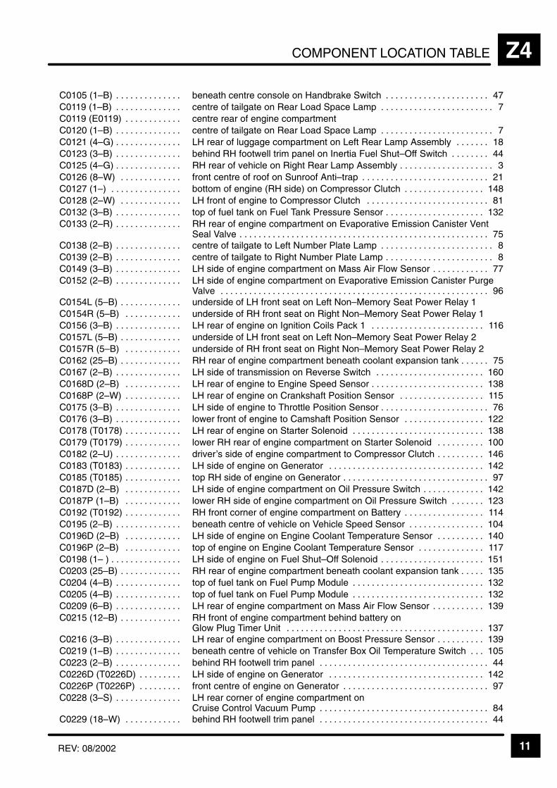
COMPONENT LOCATION TABLE Z4
11REV: 08/2002
ÁÁÁÁÁÁÁÁÁÁÁÁÁÁÁÁÁÁÁÁÁÁ
C0105 (1–B) . . . . . . . . . . . . . . ÁÁÁÁÁÁÁÁÁÁÁÁÁÁÁÁÁÁÁÁÁÁÁÁÁÁÁÁÁÁÁÁÁÁÁÁÁÁÁÁÁÁÁÁÁÁbeneath centre console on Handbrake Switch 47. . . . . . . . . . . . . . . . . . . . . .
ÁÁÁÁÁÁÁÁÁÁÁC0119 (1–B) . . . . . . . . . . . . . . ÁÁÁÁÁÁÁÁÁÁÁÁÁÁÁÁÁÁÁÁÁÁÁcentre of tailgate on Rear Load Space Lamp 7. . . . . . . . . . . . . . . . . . . . . . . . ÁÁÁÁÁÁÁÁÁÁÁÁÁÁÁÁÁÁÁÁÁÁ
C0119 (E0119) . . . . . . . . . . . . ÁÁÁÁÁÁÁÁÁÁÁÁÁÁÁÁÁÁÁÁÁÁÁÁÁÁÁÁÁÁÁÁÁÁÁÁÁÁÁÁÁÁÁÁÁÁcentre rear of engine compartment
ÁÁÁÁÁÁÁÁÁÁÁÁÁÁÁÁÁÁÁÁÁÁ
C0120 (1–B) . . . . . . . . . . . . . . ÁÁÁÁÁÁÁÁÁÁÁÁÁÁÁÁÁÁÁÁÁÁÁÁÁÁÁÁÁÁÁÁÁÁÁÁÁÁÁÁÁÁÁÁÁÁcentre of tailgate on Rear Load Space Lamp 7. . . . . . . . . . . . . . . . . . . . . . . .
ÁÁÁÁÁÁÁÁÁÁÁÁÁÁÁÁÁÁÁÁÁÁ
C0121 (4–G) . . . . . . . . . . . . . . ÁÁÁÁÁÁÁÁÁÁÁÁÁÁÁÁÁÁÁÁÁÁÁÁÁÁÁÁÁÁÁÁÁÁÁÁÁÁÁÁÁÁÁÁÁÁLH rear of luggage compartment on Left Rear Lamp Assembly 18. . . . . . .
ÁÁÁÁÁÁÁÁÁÁÁÁÁÁÁÁÁÁÁÁÁÁ
C0123 (3–B) . . . . . . . . . . . . . . ÁÁÁÁÁÁÁÁÁÁÁÁÁÁÁÁÁÁÁÁÁÁÁÁÁÁÁÁÁÁÁÁÁÁÁÁÁÁÁÁÁÁÁÁÁÁbehind RH footwell trim panel on Inertia Fuel Shut–Off Switch 44. . . . . . . .
ÁÁÁÁÁÁÁÁÁÁÁC0125 (4–G) . . . . . . . . . . . . . . ÁÁÁÁÁÁÁÁÁÁÁÁÁÁÁÁÁÁÁÁÁÁÁRH rear of vehicle on Right Rear Lamp Assembly 3. . . . . . . . . . . . . . . . . . . . ÁÁÁÁÁÁÁÁÁÁÁÁÁÁÁÁÁÁÁÁÁÁC0126 (8–W) . . . . . . . . . . . . .
ÁÁÁÁÁÁÁÁÁÁÁÁÁÁÁÁÁÁÁÁÁÁÁÁÁÁÁÁÁÁÁÁÁÁÁÁÁÁÁÁÁÁÁÁÁÁfront centre of roof on Sunroof Anti–trap 21. . . . . . . . . . . . . . . . . . . . . . . . . . . ÁÁÁÁÁÁÁÁÁÁÁ
ÁÁÁÁÁÁÁÁÁÁÁC0127 (1–) . . . . . . . . . . . . . . . ÁÁÁÁÁÁÁÁÁÁÁÁÁÁÁÁÁÁÁÁÁÁÁ
ÁÁÁÁÁÁÁÁÁÁÁÁÁÁÁÁÁÁÁÁÁÁÁbottom of engine (RH side) on Compressor Clutch 148. . . . . . . . . . . . . . . . .
ÁÁÁÁÁÁÁÁÁÁÁÁÁÁÁÁÁÁÁÁÁÁ
C0128 (2–W) . . . . . . . . . . . . . ÁÁÁÁÁÁÁÁÁÁÁÁÁÁÁÁÁÁÁÁÁÁÁÁÁÁÁÁÁÁÁÁÁÁÁÁÁÁÁÁÁÁÁÁÁÁLH front of engine to Compressor Clutch 81. . . . . . . . . . . . . . . . . . . . . . . . . .
ÁÁÁÁÁÁÁÁÁÁÁÁÁÁÁÁÁÁÁÁÁÁ
C0132 (3–B) . . . . . . . . . . . . . . ÁÁÁÁÁÁÁÁÁÁÁÁÁÁÁÁÁÁÁÁÁÁÁÁÁÁÁÁÁÁÁÁÁÁÁÁÁÁÁÁÁÁÁÁÁÁtop of fuel tank on Fuel Tank Pressure Sensor 132. . . . . . . . . . . . . . . . . . . . .
ÁÁÁÁÁÁÁÁÁÁÁÁÁÁÁÁÁÁÁÁÁÁ
C0133 (2–R) . . . . . . . . . . . . . . ÁÁÁÁÁÁÁÁÁÁÁÁÁÁÁÁÁÁÁÁÁÁÁÁÁÁÁÁÁÁÁÁÁÁÁÁÁÁÁÁÁÁÁÁÁÁRH rear of engine compartment on Evaporative Emission Canister VentSeal Valve 75. . . . . . . . . . . . . . . . . . . . . . . . . . . . . . . . . . . . . . . . . . . . . . . . . . . . . ÁÁÁÁÁÁÁÁÁÁÁ
ÁÁÁÁÁÁÁÁÁÁÁC0138 (2–B) . . . . . . . . . . . . . . ÁÁÁÁÁÁÁÁÁÁÁÁÁÁÁÁÁÁÁÁÁÁÁ
ÁÁÁÁÁÁÁÁÁÁÁÁÁÁÁÁÁÁÁÁÁÁÁcentre of tailgate to Left Number Plate Lamp 8. . . . . . . . . . . . . . . . . . . . . . . .
ÁÁÁÁÁÁÁÁÁÁÁÁÁÁÁÁÁÁÁÁÁÁ
C0139 (2–B) . . . . . . . . . . . . . . ÁÁÁÁÁÁÁÁÁÁÁÁÁÁÁÁÁÁÁÁÁÁÁÁÁÁÁÁÁÁÁÁÁÁÁÁÁÁÁÁÁÁÁÁÁÁcentre of tailgate to Right Number Plate Lamp 8. . . . . . . . . . . . . . . . . . . . . . .
ÁÁÁÁÁÁÁÁÁÁÁÁÁÁÁÁÁÁÁÁÁÁ
C0149 (3–B) . . . . . . . . . . . . . . ÁÁÁÁÁÁÁÁÁÁÁÁÁÁÁÁÁÁÁÁÁÁÁÁÁÁÁÁÁÁÁÁÁÁÁÁÁÁÁÁÁÁÁÁÁÁLH side of engine compartment on Mass Air Flow Sensor 77. . . . . . . . . . . .
ÁÁÁÁÁÁÁÁÁÁÁÁÁÁÁÁÁÁÁÁÁÁ
C0152 (2–B) . . . . . . . . . . . . . . ÁÁÁÁÁÁÁÁÁÁÁÁÁÁÁÁÁÁÁÁÁÁÁÁÁÁÁÁÁÁÁÁÁÁÁÁÁÁÁÁÁÁÁÁÁÁ
LH side of engine compartment on Evaporative Emission Canister PurgeValve 96. . . . . . . . . . . . . . . . . . . . . . . . . . . . . . . . . . . . . . . . . . . . . . . . . . . . . . . . .
ÁÁÁÁÁÁÁÁÁÁÁÁÁÁÁÁÁÁÁÁÁÁ
C0154L (5–B) . . . . . . . . . . . . . ÁÁÁÁÁÁÁÁÁÁÁÁÁÁÁÁÁÁÁÁÁÁÁÁÁÁÁÁÁÁÁÁÁÁÁÁÁÁÁÁÁÁÁÁÁÁunderside of LH front seat on Left Non–Memory Seat Power Relay 1
ÁÁÁÁÁÁÁÁÁÁÁÁÁÁÁÁÁÁÁÁÁÁ
C0154R (5–B) . . . . . . . . . . . . ÁÁÁÁÁÁÁÁÁÁÁÁÁÁÁÁÁÁÁÁÁÁÁÁÁÁÁÁÁÁÁÁÁÁÁÁÁÁÁÁÁÁÁÁÁÁunderside of RH front seat on Right Non–Memory Seat Power Relay 1
ÁÁÁÁÁÁÁÁÁÁÁÁÁÁÁÁÁÁÁÁÁÁ
C0156 (3–B) . . . . . . . . . . . . . . ÁÁÁÁÁÁÁÁÁÁÁÁÁÁÁÁÁÁÁÁÁÁÁÁÁÁÁÁÁÁÁÁÁÁÁÁÁÁÁÁÁÁÁÁÁÁLH rear of engine on Ignition Coils Pack 1 116. . . . . . . . . . . . . . . . . . . . . . . .
ÁÁÁÁÁÁÁÁÁÁÁC0157L (5–B) . . . . . . . . . . . . . ÁÁÁÁÁÁÁÁÁÁÁÁÁÁÁÁÁÁÁÁÁÁÁunderside of LH front seat on Left Non–Memory Seat Power Relay 2ÁÁÁÁÁÁÁÁÁÁÁÁÁÁÁÁÁÁÁÁÁÁ
C0157R (5–B) . . . . . . . . . . . . ÁÁÁÁÁÁÁÁÁÁÁÁÁÁÁÁÁÁÁÁÁÁÁÁÁÁÁÁÁÁÁÁÁÁÁÁÁÁÁÁÁÁÁÁÁÁunderside of RH front seat on Right Non–Memory Seat Power Relay 2
ÁÁÁÁÁÁÁÁÁÁÁÁÁÁÁÁÁÁÁÁÁÁ
C0162 (25–B) . . . . . . . . . . . . . ÁÁÁÁÁÁÁÁÁÁÁÁÁÁÁÁÁÁÁÁÁÁÁÁÁÁÁÁÁÁÁÁÁÁÁÁÁÁÁÁÁÁÁÁÁÁRH rear of engine compartment beneath coolant expansion tank 75. . . . . .
ÁÁÁÁÁÁÁÁÁÁÁÁÁÁÁÁÁÁÁÁÁÁ
C0167 (2–B) . . . . . . . . . . . . . . ÁÁÁÁÁÁÁÁÁÁÁÁÁÁÁÁÁÁÁÁÁÁÁÁÁÁÁÁÁÁÁÁÁÁÁÁÁÁÁÁÁÁÁÁÁÁLH side of transmission on Reverse Switch 160. . . . . . . . . . . . . . . . . . . . . . .
ÁÁÁÁÁÁÁÁÁÁÁÁÁÁÁÁÁÁÁÁÁÁ
C0168D (2–B) . . . . . . . . . . . . ÁÁÁÁÁÁÁÁÁÁÁÁÁÁÁÁÁÁÁÁÁÁÁÁÁÁÁÁÁÁÁÁÁÁÁÁÁÁÁÁÁÁÁÁÁÁLH rear of engine to Engine Speed Sensor 138. . . . . . . . . . . . . . . . . . . . . . . .
ÁÁÁÁÁÁÁÁÁÁÁC0168P (2–W) . . . . . . . . . . . . ÁÁÁÁÁÁÁÁÁÁÁÁÁÁÁÁÁÁÁÁÁÁÁLH rear of engine on Crankshaft Position Sensor 115. . . . . . . . . . . . . . . . . . ÁÁÁÁÁÁÁÁÁÁÁÁÁÁÁÁÁÁÁÁÁÁC0175 (3–B) . . . . . . . . . . . . . .
ÁÁÁÁÁÁÁÁÁÁÁÁÁÁÁÁÁÁÁÁÁÁÁÁÁÁÁÁÁÁÁÁÁÁÁÁÁÁÁÁÁÁÁÁÁÁLH side of engine to Throttle Position Sensor 76. . . . . . . . . . . . . . . . . . . . . . . ÁÁÁÁÁÁÁÁÁÁÁ
ÁÁÁÁÁÁÁÁÁÁÁC0176 (3–B) . . . . . . . . . . . . . . ÁÁÁÁÁÁÁÁÁÁÁÁÁÁÁÁÁÁÁÁÁÁÁ
ÁÁÁÁÁÁÁÁÁÁÁÁÁÁÁÁÁÁÁÁÁÁÁlower front of engine to Camshaft Position Sensor 122. . . . . . . . . . . . . . . . .
ÁÁÁÁÁÁÁÁÁÁÁÁÁÁÁÁÁÁÁÁÁÁ
C0178 (T0178) . . . . . . . . . . . . ÁÁÁÁÁÁÁÁÁÁÁÁÁÁÁÁÁÁÁÁÁÁÁÁÁÁÁÁÁÁÁÁÁÁÁÁÁÁÁÁÁÁÁÁÁÁLH rear of engine on Starter Solenoid 138. . . . . . . . . . . . . . . . . . . . . . . . . . . .
ÁÁÁÁÁÁÁÁÁÁÁÁÁÁÁÁÁÁÁÁÁÁ
C0179 (T0179) . . . . . . . . . . . . ÁÁÁÁÁÁÁÁÁÁÁÁÁÁÁÁÁÁÁÁÁÁÁÁÁÁÁÁÁÁÁÁÁÁÁÁÁÁÁÁÁÁÁÁÁÁlower RH rear of engine compartment on Starter Solenoid 100. . . . . . . . . .
ÁÁÁÁÁÁÁÁÁÁÁÁÁÁÁÁÁÁÁÁÁÁ
C0182 (2–U) . . . . . . . . . . . . . . ÁÁÁÁÁÁÁÁÁÁÁÁÁÁÁÁÁÁÁÁÁÁÁÁÁÁÁÁÁÁÁÁÁÁÁÁÁÁÁÁÁÁÁÁÁÁdriver’s side of engine compartment to Compressor Clutch 146. . . . . . . . . .
ÁÁÁÁÁÁÁÁÁÁÁC0183 (T0183) . . . . . . . . . . . . ÁÁÁÁÁÁÁÁÁÁÁÁÁÁÁÁÁÁÁÁÁÁÁLH side of engine on Generator 142. . . . . . . . . . . . . . . . . . . . . . . . . . . . . . . . . ÁÁÁÁÁÁÁÁÁÁÁÁÁÁÁÁÁÁÁÁÁÁ
C0185 (T0185) . . . . . . . . . . . . ÁÁÁÁÁÁÁÁÁÁÁÁÁÁÁÁÁÁÁÁÁÁÁÁÁÁÁÁÁÁÁÁÁÁÁÁÁÁÁÁÁÁÁÁÁÁtop RH side of engine on Generator 97. . . . . . . . . . . . . . . . . . . . . . . . . . . . . . .
ÁÁÁÁÁÁÁÁÁÁÁÁÁÁÁÁÁÁÁÁÁÁ
C0187D (2–B) . . . . . . . . . . . . ÁÁÁÁÁÁÁÁÁÁÁÁÁÁÁÁÁÁÁÁÁÁÁÁÁÁÁÁÁÁÁÁÁÁÁÁÁÁÁÁÁÁÁÁÁÁLH side of engine compartment on Oil Pressure Switch 142. . . . . . . . . . . . .
ÁÁÁÁÁÁÁÁÁÁÁÁÁÁÁÁÁÁÁÁÁÁ
C0187P (1–B) . . . . . . . . . . . . ÁÁÁÁÁÁÁÁÁÁÁÁÁÁÁÁÁÁÁÁÁÁÁÁÁÁÁÁÁÁÁÁÁÁÁÁÁÁÁÁÁÁÁÁÁÁlower RH side of engine compartment on Oil Pressure Switch 123. . . . . . .
ÁÁÁÁÁÁÁÁÁÁÁÁÁÁÁÁÁÁÁÁÁÁ
C0192 (T0192) . . . . . . . . . . . . ÁÁÁÁÁÁÁÁÁÁÁÁÁÁÁÁÁÁÁÁÁÁÁÁÁÁÁÁÁÁÁÁÁÁÁÁÁÁÁÁÁÁÁÁÁÁRH front corner of engine compartment on Battery 114. . . . . . . . . . . . . . . . .
ÁÁÁÁÁÁÁÁÁÁÁC0195 (2–B) . . . . . . . . . . . . . . ÁÁÁÁÁÁÁÁÁÁÁÁÁÁÁÁÁÁÁÁÁÁÁbeneath centre of vehicle on Vehicle Speed Sensor 104. . . . . . . . . . . . . . . . ÁÁÁÁÁÁÁÁÁÁÁÁÁÁÁÁÁÁÁÁÁÁ
C0196D (2–B) . . . . . . . . . . . . ÁÁÁÁÁÁÁÁÁÁÁÁÁÁÁÁÁÁÁÁÁÁÁÁÁÁÁÁÁÁÁÁÁÁÁÁÁÁÁÁÁÁÁÁÁÁLH side of engine on Engine Coolant Temperature Sensor 140. . . . . . . . . .
ÁÁÁÁÁÁÁÁÁÁÁÁÁÁÁÁÁÁÁÁÁÁ
C0196P (2–B) . . . . . . . . . . . . ÁÁÁÁÁÁÁÁÁÁÁÁÁÁÁÁÁÁÁÁÁÁÁÁÁÁÁÁÁÁÁÁÁÁÁÁÁÁÁÁÁÁÁÁÁÁtop of engine on Engine Coolant Temperature Sensor 117. . . . . . . . . . . . . .
ÁÁÁÁÁÁÁÁÁÁÁÁÁÁÁÁÁÁÁÁÁÁ
C0198 (1– ) . . . . . . . . . . . . . . . ÁÁÁÁÁÁÁÁÁÁÁÁÁÁÁÁÁÁÁÁÁÁÁÁÁÁÁÁÁÁÁÁÁÁÁÁÁÁÁÁÁÁÁÁÁÁLH side of engine on Fuel Shut–Off Solenoid 151. . . . . . . . . . . . . . . . . . . . . .
ÁÁÁÁÁÁÁÁÁÁÁÁÁÁÁÁÁÁÁÁÁÁ
C0203 (25–B) . . . . . . . . . . . . . ÁÁÁÁÁÁÁÁÁÁÁÁÁÁÁÁÁÁÁÁÁÁÁÁÁÁÁÁÁÁÁÁÁÁÁÁÁÁÁÁÁÁÁÁÁÁRH rear of engine compartment beneath coolant expansion tank 135. . . . .
ÁÁÁÁÁÁÁÁÁÁÁC0204 (4–B) . . . . . . . . . . . . . . ÁÁÁÁÁÁÁÁÁÁÁÁÁÁÁÁÁÁÁÁÁÁÁtop of fuel tank on Fuel Pump Module 132. . . . . . . . . . . . . . . . . . . . . . . . . . . . ÁÁÁÁÁÁÁÁÁÁÁÁÁÁÁÁÁÁÁÁÁÁC0205 (4–B) . . . . . . . . . . . . . .
ÁÁÁÁÁÁÁÁÁÁÁÁÁÁÁÁÁÁÁÁÁÁÁÁÁÁÁÁÁÁÁÁÁÁÁÁÁÁÁÁÁÁÁÁÁÁtop of fuel tank on Fuel Pump Module 132. . . . . . . . . . . . . . . . . . . . . . . . . . . . ÁÁÁÁÁÁÁÁÁÁÁ
ÁÁÁÁÁÁÁÁÁÁÁC0209 (6–B) . . . . . . . . . . . . . . ÁÁÁÁÁÁÁÁÁÁÁÁÁÁÁÁÁÁÁÁÁÁÁ
ÁÁÁÁÁÁÁÁÁÁÁÁÁÁÁÁÁÁÁÁÁÁÁLH rear of engine compartment on Mass Air Flow Sensor 139. . . . . . . . . . .
ÁÁÁÁÁÁÁÁÁÁÁÁÁÁÁÁÁÁÁÁÁÁÁÁÁÁÁÁÁÁÁÁÁ
C0215 (12–B) . . . . . . . . . . . . . ÁÁÁÁÁÁÁÁÁÁÁÁÁÁÁÁÁÁÁÁÁÁÁÁÁÁÁÁÁÁÁÁÁÁÁÁÁÁÁÁÁÁÁÁÁÁÁÁÁÁÁÁÁÁÁÁÁÁÁÁÁÁÁÁÁÁÁÁÁ
RH front of engine compartment behind battery on Glow Plug Timer Unit 137. . . . . . . . . . . . . . . . . . . . . . . . . . . . . . . . . . . . . . . . . .
ÁÁÁÁÁÁÁÁÁÁÁC0216 (3–B) . . . . . . . . . . . . . . ÁÁÁÁÁÁÁÁÁÁÁÁÁÁÁÁÁÁÁÁÁÁÁLH rear of engine compartment on Boost Pressure Sensor 139. . . . . . . . . . ÁÁÁÁÁÁÁÁÁÁÁÁÁÁÁÁÁÁÁÁÁÁ
C0219 (1–B) . . . . . . . . . . . . . . ÁÁÁÁÁÁÁÁÁÁÁÁÁÁÁÁÁÁÁÁÁÁÁÁÁÁÁÁÁÁÁÁÁÁÁÁÁÁÁÁÁÁÁÁÁÁbeneath centre of vehicle on Transfer Box Oil Temperature Switch 105. . .
ÁÁÁÁÁÁÁÁÁÁÁÁÁÁÁÁÁÁÁÁÁÁ
C0223 (2–B) . . . . . . . . . . . . . . ÁÁÁÁÁÁÁÁÁÁÁÁÁÁÁÁÁÁÁÁÁÁÁÁÁÁÁÁÁÁÁÁÁÁÁÁÁÁÁÁÁÁÁÁÁÁbehind RH footwell trim panel 44. . . . . . . . . . . . . . . . . . . . . . . . . . . . . . . . . . . .
ÁÁÁÁÁÁÁÁÁÁÁÁÁÁÁÁÁÁÁÁÁÁ
C0226D (T0226D) . . . . . . . . . ÁÁÁÁÁÁÁÁÁÁÁÁÁÁÁÁÁÁÁÁÁÁÁÁÁÁÁÁÁÁÁÁÁÁÁÁÁÁÁÁÁÁÁÁÁÁLH side of engine on Generator 142. . . . . . . . . . . . . . . . . . . . . . . . . . . . . . . . .
ÁÁÁÁÁÁÁÁÁÁÁÁÁÁÁÁÁÁÁÁÁÁ
C0226P (T0226P) . . . . . . . . . ÁÁÁÁÁÁÁÁÁÁÁÁÁÁÁÁÁÁÁÁÁÁÁÁÁÁÁÁÁÁÁÁÁÁÁÁÁÁÁÁÁÁÁÁÁÁfront centre of engine on Generator 97. . . . . . . . . . . . . . . . . . . . . . . . . . . . . . .
ÁÁÁÁÁÁÁÁÁÁÁÁÁÁÁÁÁÁÁÁÁÁ
C0228 (3–S) . . . . . . . . . . . . . . ÁÁÁÁÁÁÁÁÁÁÁÁÁÁÁÁÁÁÁÁÁÁÁÁÁÁÁÁÁÁÁÁÁÁÁÁÁÁÁÁÁÁÁÁÁÁ
LH rear corner of engine compartment on Cruise Control Vacuum Pump 84. . . . . . . . . . . . . . . . . . . . . . . . . . . . . . . . . . . .
ÁÁÁÁÁÁÁÁÁÁÁÁÁÁÁÁÁÁÁÁÁÁ
C0229 (18–W) . . . . . . . . . . . . ÁÁÁÁÁÁÁÁÁÁÁÁÁÁÁÁÁÁÁÁÁÁÁÁÁÁÁÁÁÁÁÁÁÁÁÁÁÁÁÁÁÁÁÁÁÁbehind RH footwell trim panel 44. . . . . . . . . . . . . . . . . . . . . . . . . . . . . . . . . . . .
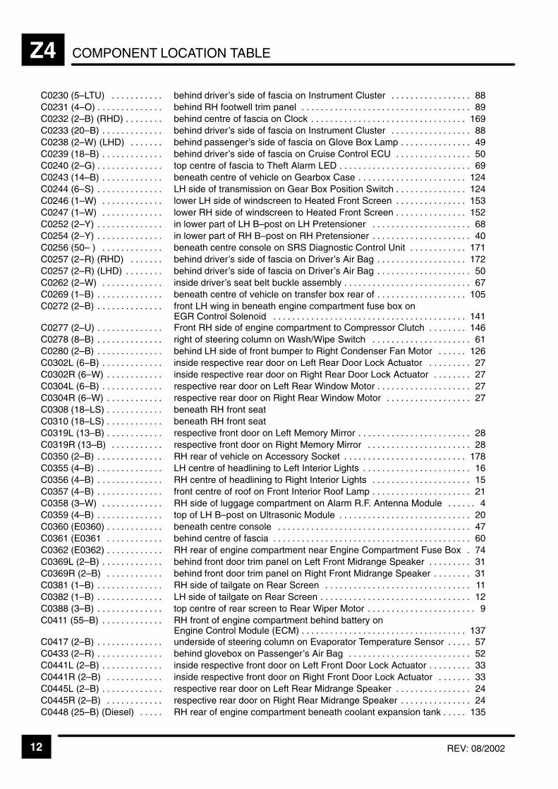
COMPONENT LOCATION TABLEZ4
12 REV: 08/2002
ÁÁÁÁÁÁÁÁÁÁÁÁÁÁÁÁÁÁÁÁ
C0230 (5–LTU) . . . . . . . . . . . ÁÁÁÁÁÁÁÁÁÁÁÁÁÁÁÁÁÁÁÁÁÁÁÁÁÁÁÁÁÁÁÁÁÁÁÁÁÁÁÁÁÁÁÁÁÁ
behind driver’s side of fascia on Instrument Cluster 88. . . . . . . . . . . . . . . . .
ÁÁÁÁÁÁÁÁÁÁC0231 (4–O) . . . . . . . . . . . . . . ÁÁÁÁÁÁÁÁÁÁÁÁÁÁÁÁÁÁÁÁÁÁÁbehind RH footwell trim panel 89. . . . . . . . . . . . . . . . . . . . . . . . . . . . . . . . . . . . ÁÁÁÁÁÁÁÁÁÁÁÁÁÁÁÁÁÁÁÁ
C0232 (2–B) (RHD) . . . . . . . . ÁÁÁÁÁÁÁÁÁÁÁÁÁÁÁÁÁÁÁÁÁÁÁÁÁÁÁÁÁÁÁÁÁÁÁÁÁÁÁÁÁÁÁÁÁÁ
behind centre of fascia on Clock 169. . . . . . . . . . . . . . . . . . . . . . . . . . . . . . . . . ÁÁÁÁÁÁÁÁÁÁÁÁÁÁÁÁÁÁÁÁ
C0233 (20–B) . . . . . . . . . . . . . ÁÁÁÁÁÁÁÁÁÁÁÁÁÁÁÁÁÁÁÁÁÁÁÁÁÁÁÁÁÁÁÁÁÁÁÁÁÁÁÁÁÁÁÁÁÁ
behind driver’s side of fascia on Instrument Cluster 88. . . . . . . . . . . . . . . . . ÁÁÁÁÁÁÁÁÁÁÁÁÁÁÁÁÁÁÁÁ
C0238 (2–W) (LHD) . . . . . . . ÁÁÁÁÁÁÁÁÁÁÁÁÁÁÁÁÁÁÁÁÁÁÁÁÁÁÁÁÁÁÁÁÁÁÁÁÁÁÁÁÁÁÁÁÁÁ
behind passenger’s side of fascia on Glove Box Lamp 49. . . . . . . . . . . . . . . ÁÁÁÁÁÁÁÁÁÁÁÁÁÁÁÁÁÁÁÁ
C0239 (18–B) . . . . . . . . . . . . . ÁÁÁÁÁÁÁÁÁÁÁÁÁÁÁÁÁÁÁÁÁÁÁÁÁÁÁÁÁÁÁÁÁÁÁÁÁÁÁÁÁÁÁÁÁÁ
behind driver’s side of fascia on Cruise Control ECU 50. . . . . . . . . . . . . . . .
ÁÁÁÁÁÁÁÁÁÁC0240 (2–G) . . . . . . . . . . . . . . ÁÁÁÁÁÁÁÁÁÁÁÁÁÁÁÁÁÁÁÁÁÁÁtop centre of fascia to Theft Alarm LED 69. . . . . . . . . . . . . . . . . . . . . . . . . . . . ÁÁÁÁÁÁÁÁÁÁÁÁÁÁÁÁÁÁÁÁC0243 (14–B) . . . . . . . . . . . . .
ÁÁÁÁÁÁÁÁÁÁÁÁÁÁÁÁÁÁÁÁÁÁÁÁÁÁÁÁÁÁÁÁÁÁÁÁÁÁÁÁÁÁÁÁÁÁbeneath centre of vehicle on Gearbox Case 124. . . . . . . . . . . . . . . . . . . . . . . ÁÁÁÁÁÁÁÁÁÁ
ÁÁÁÁÁÁÁÁÁÁC0244 (6–S) . . . . . . . . . . . . . . ÁÁÁÁÁÁÁÁÁÁÁÁÁÁÁÁÁÁÁÁÁÁÁ
ÁÁÁÁÁÁÁÁÁÁÁÁÁÁÁÁÁÁÁÁÁÁÁLH side of transmission on Gear Box Position Switch 124. . . . . . . . . . . . . . .
ÁÁÁÁÁÁÁÁÁÁÁÁÁÁÁÁÁÁÁÁ
C0246 (1–W) . . . . . . . . . . . . . ÁÁÁÁÁÁÁÁÁÁÁÁÁÁÁÁÁÁÁÁÁÁÁÁÁÁÁÁÁÁÁÁÁÁÁÁÁÁÁÁÁÁÁÁÁÁ
lower LH side of windscreen to Heated Front Screen 153. . . . . . . . . . . . . . . ÁÁÁÁÁÁÁÁÁÁÁÁÁÁÁÁÁÁÁÁ
C0247 (1–W) . . . . . . . . . . . . . ÁÁÁÁÁÁÁÁÁÁÁÁÁÁÁÁÁÁÁÁÁÁÁÁÁÁÁÁÁÁÁÁÁÁÁÁÁÁÁÁÁÁÁÁÁÁ
lower RH side of windscreen to Heated Front Screen 152. . . . . . . . . . . . . . .
ÁÁÁÁÁÁÁÁÁÁÁÁÁÁÁÁÁÁÁÁ
C0252 (2–Y) . . . . . . . . . . . . . . ÁÁÁÁÁÁÁÁÁÁÁÁÁÁÁÁÁÁÁÁÁÁÁÁÁÁÁÁÁÁÁÁÁÁÁÁÁÁÁÁÁÁÁÁÁÁ
in lower part of LH B–post on LH Pretensioner 68. . . . . . . . . . . . . . . . . . . . .
ÁÁÁÁÁÁÁÁÁÁC0254 (2–Y) . . . . . . . . . . . . . . ÁÁÁÁÁÁÁÁÁÁÁÁÁÁÁÁÁÁÁÁÁÁÁin lower part of RH B–post on RH Pretensioner 40. . . . . . . . . . . . . . . . . . . . . ÁÁÁÁÁÁÁÁÁÁÁÁÁÁÁÁÁÁÁÁ
C0256 (50– ) . . . . . . . . . . . . . ÁÁÁÁÁÁÁÁÁÁÁÁÁÁÁÁÁÁÁÁÁÁÁÁÁÁÁÁÁÁÁÁÁÁÁÁÁÁÁÁÁÁÁÁÁÁ
beneath centre console on SRS Diagnostic Control Unit 171. . . . . . . . . . . . ÁÁÁÁÁÁÁÁÁÁÁÁÁÁÁÁÁÁÁÁ
C0257 (2–R) (RHD) . . . . . . . ÁÁÁÁÁÁÁÁÁÁÁÁÁÁÁÁÁÁÁÁÁÁÁÁÁÁÁÁÁÁÁÁÁÁÁÁÁÁÁÁÁÁÁÁÁÁ
behind driver’s side of fascia on Driver’s Air Bag 172. . . . . . . . . . . . . . . . . . . ÁÁÁÁÁÁÁÁÁÁÁÁÁÁÁÁÁÁÁÁ
C0257 (2–R) (LHD) . . . . . . . . ÁÁÁÁÁÁÁÁÁÁÁÁÁÁÁÁÁÁÁÁÁÁÁÁÁÁÁÁÁÁÁÁÁÁÁÁÁÁÁÁÁÁÁÁÁÁ
behind driver’s side of fascia on Driver’s Air Bag 50. . . . . . . . . . . . . . . . . . . .
ÁÁÁÁÁÁÁÁÁÁÁÁÁÁÁÁÁÁÁÁ
C0262 (2–W) . . . . . . . . . . . . . ÁÁÁÁÁÁÁÁÁÁÁÁÁÁÁÁÁÁÁÁÁÁÁÁÁÁÁÁÁÁÁÁÁÁÁÁÁÁÁÁÁÁÁÁÁÁ
inside driver’s seat belt buckle assembly 67. . . . . . . . . . . . . . . . . . . . . . . . . . .
ÁÁÁÁÁÁÁÁÁÁC0269 (1–B) . . . . . . . . . . . . . . ÁÁÁÁÁÁÁÁÁÁÁÁÁÁÁÁÁÁÁÁÁÁÁbeneath centre of vehicle on transfer box rear of 105. . . . . . . . . . . . . . . . . . . ÁÁÁÁÁÁÁÁÁÁÁÁÁÁÁÁÁÁÁÁÁÁÁÁÁÁÁÁÁÁ
C0272 (2–B) . . . . . . . . . . . . . . ÁÁÁÁÁÁÁÁÁÁÁÁÁÁÁÁÁÁÁÁÁÁÁÁÁÁÁÁÁÁÁÁÁÁÁÁÁÁÁÁÁÁÁÁÁÁÁÁÁÁÁÁÁÁÁÁÁÁÁÁÁÁÁÁÁÁÁÁÁ
front LH wing in beneath engine compartment fuse box on EGR Control Solenoid 141. . . . . . . . . . . . . . . . . . . . . . . . . . . . . . . . . . . . . . . . .
ÁÁÁÁÁÁÁÁÁÁÁÁÁÁÁÁÁÁÁÁ
C0277 (2–U) . . . . . . . . . . . . . . ÁÁÁÁÁÁÁÁÁÁÁÁÁÁÁÁÁÁÁÁÁÁÁÁÁÁÁÁÁÁÁÁÁÁÁÁÁÁÁÁÁÁÁÁÁÁ
Front RH side of engine compartment to Compressor Clutch 146. . . . . . . .
ÁÁÁÁÁÁÁÁÁÁÁÁÁÁÁÁÁÁÁÁ
C0278 (8–B) . . . . . . . . . . . . . . ÁÁÁÁÁÁÁÁÁÁÁÁÁÁÁÁÁÁÁÁÁÁÁÁÁÁÁÁÁÁÁÁÁÁÁÁÁÁÁÁÁÁÁÁÁÁ
right of steering column on Wash/Wipe Switch 61. . . . . . . . . . . . . . . . . . . . .
ÁÁÁÁÁÁÁÁÁÁC0280 (2–B) . . . . . . . . . . . . . . ÁÁÁÁÁÁÁÁÁÁÁÁÁÁÁÁÁÁÁÁÁÁÁbehind LH side of front bumper to Right Condenser Fan Motor 126. . . . . . ÁÁÁÁÁÁÁÁÁÁÁÁÁÁÁÁÁÁÁÁ
C0302L (6–B) . . . . . . . . . . . . . ÁÁÁÁÁÁÁÁÁÁÁÁÁÁÁÁÁÁÁÁÁÁÁÁÁÁÁÁÁÁÁÁÁÁÁÁÁÁÁÁÁÁÁÁÁÁ
inside respective rear door on Left Rear Door Lock Actuator 27. . . . . . . . . ÁÁÁÁÁÁÁÁÁÁÁÁÁÁÁÁÁÁÁÁ
C0302R (6–W) . . . . . . . . . . . . ÁÁÁÁÁÁÁÁÁÁÁÁÁÁÁÁÁÁÁÁÁÁÁÁÁÁÁÁÁÁÁÁÁÁÁÁÁÁÁÁÁÁÁÁÁÁ
inside respective rear door on Right Rear Door Lock Actuator 27. . . . . . . . ÁÁÁÁÁÁÁÁÁÁÁÁÁÁÁÁÁÁÁÁ
C0304L (6–B) . . . . . . . . . . . . . ÁÁÁÁÁÁÁÁÁÁÁÁÁÁÁÁÁÁÁÁÁÁÁÁÁÁÁÁÁÁÁÁÁÁÁÁÁÁÁÁÁÁÁÁÁÁ
respective rear door on Left Rear Window Motor 27. . . . . . . . . . . . . . . . . . . .
ÁÁÁÁÁÁÁÁÁÁÁÁÁÁÁÁÁÁÁÁ
C0304R (6–W) . . . . . . . . . . . . ÁÁÁÁÁÁÁÁÁÁÁÁÁÁÁÁÁÁÁÁÁÁÁÁÁÁÁÁÁÁÁÁÁÁÁÁÁÁÁÁÁÁÁÁÁÁ
respective rear door on Right Rear Window Motor 27. . . . . . . . . . . . . . . . . .
ÁÁÁÁÁÁÁÁÁÁC0308 (18–LS) . . . . . . . . . . . . ÁÁÁÁÁÁÁÁÁÁÁÁÁÁÁÁÁÁÁÁÁÁÁbeneath RH front seatÁÁÁÁÁÁÁÁÁÁÁÁÁÁÁÁÁÁÁÁ
C0310 (18–LS) . . . . . . . . . . . . ÁÁÁÁÁÁÁÁÁÁÁÁÁÁÁÁÁÁÁÁÁÁÁÁÁÁÁÁÁÁÁÁÁÁÁÁÁÁÁÁÁÁÁÁÁÁ
beneath RH front seatÁÁÁÁÁÁÁÁÁÁÁÁÁÁÁÁÁÁÁÁ
C0319L (13–B) . . . . . . . . . . . . ÁÁÁÁÁÁÁÁÁÁÁÁÁÁÁÁÁÁÁÁÁÁÁÁÁÁÁÁÁÁÁÁÁÁÁÁÁÁÁÁÁÁÁÁÁÁ
respective front door on Left Memory Mirror 28. . . . . . . . . . . . . . . . . . . . . . . . ÁÁÁÁÁÁÁÁÁÁÁÁÁÁÁÁÁÁÁÁ
C0319R (13–B) . . . . . . . . . . . ÁÁÁÁÁÁÁÁÁÁÁÁÁÁÁÁÁÁÁÁÁÁÁÁÁÁÁÁÁÁÁÁÁÁÁÁÁÁÁÁÁÁÁÁÁÁ
respective front door on Right Memory Mirror 28. . . . . . . . . . . . . . . . . . . . . . ÁÁÁÁÁÁÁÁÁÁÁÁÁÁÁÁÁÁÁÁ
C0350 (2–B) . . . . . . . . . . . . . . ÁÁÁÁÁÁÁÁÁÁÁÁÁÁÁÁÁÁÁÁÁÁÁÁÁÁÁÁÁÁÁÁÁÁÁÁÁÁÁÁÁÁÁÁÁÁ
RH rear of vehicle on Accessory Socket 178. . . . . . . . . . . . . . . . . . . . . . . . . .
ÁÁÁÁÁÁÁÁÁÁC0355 (4–B) . . . . . . . . . . . . . . ÁÁÁÁÁÁÁÁÁÁÁÁÁÁÁÁÁÁÁÁÁÁÁLH centre of headlining to Left Interior Lights 16. . . . . . . . . . . . . . . . . . . . . . . ÁÁÁÁÁÁÁÁÁÁÁÁÁÁÁÁÁÁÁÁC0356 (4–B) . . . . . . . . . . . . . .
ÁÁÁÁÁÁÁÁÁÁÁÁÁÁÁÁÁÁÁÁÁÁÁÁÁÁÁÁÁÁÁÁÁÁÁÁÁÁÁÁÁÁÁÁÁÁRH centre of headlining to Right Interior Lights 15. . . . . . . . . . . . . . . . . . . . . ÁÁÁÁÁÁÁÁÁÁ
ÁÁÁÁÁÁÁÁÁÁC0357 (4–B) . . . . . . . . . . . . . . ÁÁÁÁÁÁÁÁÁÁÁÁÁÁÁÁÁÁÁÁÁÁÁ
ÁÁÁÁÁÁÁÁÁÁÁÁÁÁÁÁÁÁÁÁÁÁÁfront centre of roof on Front Interior Roof Lamp 21. . . . . . . . . . . . . . . . . . . . .
ÁÁÁÁÁÁÁÁÁÁÁÁÁÁÁÁÁÁÁÁ
C0358 (3–W) . . . . . . . . . . . . . ÁÁÁÁÁÁÁÁÁÁÁÁÁÁÁÁÁÁÁÁÁÁÁÁÁÁÁÁÁÁÁÁÁÁÁÁÁÁÁÁÁÁÁÁÁÁ
RH side of luggage compartment on Alarm R.F. Antenna Module 4. . . . . . ÁÁÁÁÁÁÁÁÁÁÁÁÁÁÁÁÁÁÁÁ
C0359 (4–B) . . . . . . . . . . . . . . ÁÁÁÁÁÁÁÁÁÁÁÁÁÁÁÁÁÁÁÁÁÁÁÁÁÁÁÁÁÁÁÁÁÁÁÁÁÁÁÁÁÁÁÁÁÁ
top of LH B–post on Ultrasonic Module 20. . . . . . . . . . . . . . . . . . . . . . . . . . . .
ÁÁÁÁÁÁÁÁÁÁÁÁÁÁÁÁÁÁÁÁ
C0360 (E0360) . . . . . . . . . . . . ÁÁÁÁÁÁÁÁÁÁÁÁÁÁÁÁÁÁÁÁÁÁÁÁÁÁÁÁÁÁÁÁÁÁÁÁÁÁÁÁÁÁÁÁÁÁ
beneath centre console 47. . . . . . . . . . . . . . . . . . . . . . . . . . . . . . . . . . . . . . . . .
ÁÁÁÁÁÁÁÁÁÁC0361 (E0361 . . . . . . . . . . . . ÁÁÁÁÁÁÁÁÁÁÁÁÁÁÁÁÁÁÁÁÁÁÁbehind centre of fascia 60. . . . . . . . . . . . . . . . . . . . . . . . . . . . . . . . . . . . . . . . . . ÁÁÁÁÁÁÁÁÁÁÁÁÁÁÁÁÁÁÁÁ
C0362 (E0362) . . . . . . . . . . . . ÁÁÁÁÁÁÁÁÁÁÁÁÁÁÁÁÁÁÁÁÁÁÁÁÁÁÁÁÁÁÁÁÁÁÁÁÁÁÁÁÁÁÁÁÁÁ
RH rear of engine compartment near Engine Compartment Fuse Box 74. ÁÁÁÁÁÁÁÁÁÁÁÁÁÁÁÁÁÁÁÁ
C0369L (2–B) . . . . . . . . . . . . . ÁÁÁÁÁÁÁÁÁÁÁÁÁÁÁÁÁÁÁÁÁÁÁÁÁÁÁÁÁÁÁÁÁÁÁÁÁÁÁÁÁÁÁÁÁÁ
behind front door trim panel on Left Front Midrange Speaker 31. . . . . . . . . ÁÁÁÁÁÁÁÁÁÁÁÁÁÁÁÁÁÁÁÁ
C0369R (2–B) . . . . . . . . . . . . ÁÁÁÁÁÁÁÁÁÁÁÁÁÁÁÁÁÁÁÁÁÁÁÁÁÁÁÁÁÁÁÁÁÁÁÁÁÁÁÁÁÁÁÁÁÁ
behind front door trim panel on Right Front Midrange Speaker 31. . . . . . . .
ÁÁÁÁÁÁÁÁÁÁÁÁÁÁÁÁÁÁÁÁ
C0381 (1–B) . . . . . . . . . . . . . . ÁÁÁÁÁÁÁÁÁÁÁÁÁÁÁÁÁÁÁÁÁÁÁÁÁÁÁÁÁÁÁÁÁÁÁÁÁÁÁÁÁÁÁÁÁÁ
RH side of tailgate on Rear Screen 11. . . . . . . . . . . . . . . . . . . . . . . . . . . . . . .
ÁÁÁÁÁÁÁÁÁÁC0382 (1–B) . . . . . . . . . . . . . . ÁÁÁÁÁÁÁÁÁÁÁÁÁÁÁÁÁÁÁÁÁÁÁLH side of tailgate on Rear Screen 12. . . . . . . . . . . . . . . . . . . . . . . . . . . . . . . . ÁÁÁÁÁÁÁÁÁÁÁÁÁÁÁÁÁÁÁÁ
C0388 (3–B) . . . . . . . . . . . . . . ÁÁÁÁÁÁÁÁÁÁÁÁÁÁÁÁÁÁÁÁÁÁÁÁÁÁÁÁÁÁÁÁÁÁÁÁÁÁÁÁÁÁÁÁÁÁ
top centre of rear screen to Rear Wiper Motor 9. . . . . . . . . . . . . . . . . . . . . . . ÁÁÁÁÁÁÁÁÁÁÁÁÁÁÁÁÁÁÁÁÁÁÁÁÁÁÁÁÁÁ
C0411 (55–B) . . . . . . . . . . . . . ÁÁÁÁÁÁÁÁÁÁÁÁÁÁÁÁÁÁÁÁÁÁÁÁÁÁÁÁÁÁÁÁÁÁÁÁÁÁÁÁÁÁÁÁÁÁÁÁÁÁÁÁÁÁÁÁÁÁÁÁÁÁÁÁÁÁÁÁÁ
RH front of engine compartment behind battery on Engine Control Module (ECM) 137. . . . . . . . . . . . . . . . . . . . . . . . . . . . . . . . . . .
ÁÁÁÁÁÁÁÁÁÁÁÁÁÁÁÁÁÁÁÁ
C0417 (2–B) . . . . . . . . . . . . . . ÁÁÁÁÁÁÁÁÁÁÁÁÁÁÁÁÁÁÁÁÁÁÁÁÁÁÁÁÁÁÁÁÁÁÁÁÁÁÁÁÁÁÁÁÁÁ
underside of steering column on Evaporator Temperature Sensor 57. . . . .
ÁÁÁÁÁÁÁÁÁÁC0433 (2–R) . . . . . . . . . . . . . . ÁÁÁÁÁÁÁÁÁÁÁÁÁÁÁÁÁÁÁÁÁÁÁbehind glovebox on Passenger’s Air Bag 52. . . . . . . . . . . . . . . . . . . . . . . . . . ÁÁÁÁÁÁÁÁÁÁÁÁÁÁÁÁÁÁÁÁ
C0441L (2–B) . . . . . . . . . . . . . ÁÁÁÁÁÁÁÁÁÁÁÁÁÁÁÁÁÁÁÁÁÁÁÁÁÁÁÁÁÁÁÁÁÁÁÁÁÁÁÁÁÁÁÁÁÁ
inside respective front door on Left Front Door Lock Actuator 33. . . . . . . . . ÁÁÁÁÁÁÁÁÁÁÁÁÁÁÁÁÁÁÁÁ
C0441R (2–B) . . . . . . . . . . . . ÁÁÁÁÁÁÁÁÁÁÁÁÁÁÁÁÁÁÁÁÁÁÁÁÁÁÁÁÁÁÁÁÁÁÁÁÁÁÁÁÁÁÁÁÁÁ
inside respective front door on Right Front Door Lock Actuator 33. . . . . . . ÁÁÁÁÁÁÁÁÁÁÁÁÁÁÁÁÁÁÁÁ
C0445L (2–B) . . . . . . . . . . . . . ÁÁÁÁÁÁÁÁÁÁÁÁÁÁÁÁÁÁÁÁÁÁÁÁÁÁÁÁÁÁÁÁÁÁÁÁÁÁÁÁÁÁÁÁÁÁ
respective rear door on Left Rear Midrange Speaker 24. . . . . . . . . . . . . . . .
ÁÁÁÁÁÁÁÁÁÁÁÁÁÁÁÁÁÁÁÁ
C0445R (2–B) . . . . . . . . . . . . ÁÁÁÁÁÁÁÁÁÁÁÁÁÁÁÁÁÁÁÁÁÁÁÁÁÁÁÁÁÁÁÁÁÁÁÁÁÁÁÁÁÁÁÁÁÁ
respective rear door on Right Rear Midrange Speaker 24. . . . . . . . . . . . . . .
ÁÁÁÁÁÁÁÁÁÁC0448 (25–B) (Diesel) . . . . . ÁÁÁÁÁÁÁÁÁÁÁÁÁÁÁÁÁÁÁÁÁÁÁRH rear of engine compartment beneath coolant expansion tank 135. . . . .
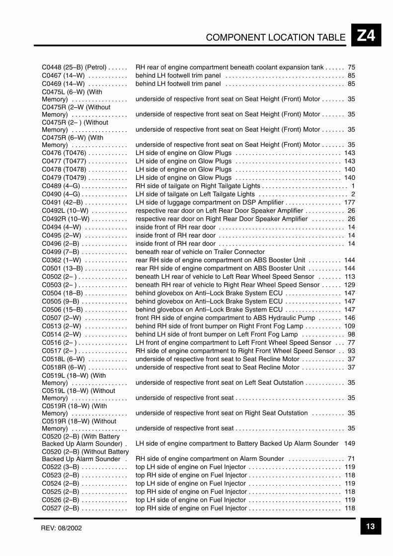
COMPONENT LOCATION TABLE Z4
13REV: 08/2002
ÁÁÁÁÁÁÁÁÁÁÁÁÁÁÁÁÁÁÁÁÁÁ
C0448 (25–B) (Petrol) . . . . . . ÁÁÁÁÁÁÁÁÁÁÁÁÁÁÁÁÁÁÁÁÁÁÁÁÁÁÁÁÁÁÁÁÁÁÁÁÁÁÁÁÁÁÁÁÁÁRH rear of engine compartment beneath coolant expansion tank 75. . . . . .
ÁÁÁÁÁÁÁÁÁÁÁC0467 (14–W) . . . . . . . . . . . . ÁÁÁÁÁÁÁÁÁÁÁÁÁÁÁÁÁÁÁÁÁÁÁbehind LH footwell trim panel 85. . . . . . . . . . . . . . . . . . . . . . . . . . . . . . . . . . . . ÁÁÁÁÁÁÁÁÁÁÁÁÁÁÁÁÁÁÁÁÁÁ
C0469 (14–W) . . . . . . . . . . . . ÁÁÁÁÁÁÁÁÁÁÁÁÁÁÁÁÁÁÁÁÁÁÁÁÁÁÁÁÁÁÁÁÁÁÁÁÁÁÁÁÁÁÁÁÁÁbehind LH footwell trim panel 85. . . . . . . . . . . . . . . . . . . . . . . . . . . . . . . . . . . .
ÁÁÁÁÁÁÁÁÁÁÁÁÁÁÁÁÁÁÁÁÁÁÁÁÁÁÁÁÁÁÁÁÁ
C0475L (6–W) (WithMemory) . . . . . . . . . . . . . . . . .
ÁÁÁÁÁÁÁÁÁÁÁÁÁÁÁÁÁÁÁÁÁÁÁÁÁÁÁÁÁÁÁÁÁÁÁÁÁÁÁÁÁÁÁÁÁÁÁÁÁÁÁÁÁÁÁÁÁÁÁÁÁÁÁÁÁÁÁÁÁunderside of respective front seat on Seat Height (Front) Motor 35. . . . . . .
ÁÁÁÁÁÁÁÁÁÁÁÁÁÁÁÁÁÁÁÁÁÁ
C0475R (2–W (WithoutMemory) . . . . . . . . . . . . . . . . .
ÁÁÁÁÁÁÁÁÁÁÁÁÁÁÁÁÁÁÁÁÁÁÁÁÁÁÁÁÁÁÁÁÁÁÁÁÁÁÁÁÁÁÁÁÁÁunderside of respective front seat on Seat Height (Front) Motor 35. . . . . . .
ÁÁÁÁÁÁÁÁÁÁÁÁÁÁÁÁÁÁÁÁÁÁÁÁÁÁÁÁÁÁÁÁÁ
C0475R (2– ) (WithoutMemory) . . . . . . . . . . . . . . . . .
ÁÁÁÁÁÁÁÁÁÁÁÁÁÁÁÁÁÁÁÁÁÁÁÁÁÁÁÁÁÁÁÁÁÁÁÁÁÁÁÁÁÁÁÁÁÁÁÁÁÁÁÁÁÁÁÁÁÁÁÁÁÁÁÁÁÁÁÁÁunderside of respective front seat on Seat Height (Front) Motor 35. . . . . . .
ÁÁÁÁÁÁÁÁÁÁÁÁÁÁÁÁÁÁÁÁÁÁ
C0475R (6–W) (WithMemory) . . . . . . . . . . . . . . . . .
ÁÁÁÁÁÁÁÁÁÁÁÁÁÁÁÁÁÁÁÁÁÁÁÁÁÁÁÁÁÁÁÁÁÁÁÁÁÁÁÁÁÁÁÁÁÁunderside of respective front seat on Seat Height (Front) Motor 35. . . . . . .
ÁÁÁÁÁÁÁÁÁÁÁÁÁÁÁÁÁÁÁÁÁÁ
C0476 (T0476) . . . . . . . . . . . . ÁÁÁÁÁÁÁÁÁÁÁÁÁÁÁÁÁÁÁÁÁÁÁÁÁÁÁÁÁÁÁÁÁÁÁÁÁÁÁÁÁÁÁÁÁÁLH side of engine on Glow Plugs 143. . . . . . . . . . . . . . . . . . . . . . . . . . . . . . . .
ÁÁÁÁÁÁÁÁÁÁÁÁÁÁÁÁÁÁÁÁÁÁ
C0477 (T0477) . . . . . . . . . . . . ÁÁÁÁÁÁÁÁÁÁÁÁÁÁÁÁÁÁÁÁÁÁÁÁÁÁÁÁÁÁÁÁÁÁÁÁÁÁÁÁÁÁÁÁÁÁLH side of engine on Glow Plugs 143. . . . . . . . . . . . . . . . . . . . . . . . . . . . . . . .
ÁÁÁÁÁÁÁÁÁÁÁÁÁÁÁÁÁÁÁÁÁÁ
C0478 (T0478) . . . . . . . . . . . . ÁÁÁÁÁÁÁÁÁÁÁÁÁÁÁÁÁÁÁÁÁÁÁÁÁÁÁÁÁÁÁÁÁÁÁÁÁÁÁÁÁÁÁÁÁÁLH side of engine on Glow Plugs 140. . . . . . . . . . . . . . . . . . . . . . . . . . . . . . . .
ÁÁÁÁÁÁÁÁÁÁÁC0479 (T0479) . . . . . . . . . . . . ÁÁÁÁÁÁÁÁÁÁÁÁÁÁÁÁÁÁÁÁÁÁÁLH side of engine on Glow Plugs 140. . . . . . . . . . . . . . . . . . . . . . . . . . . . . . . . ÁÁÁÁÁÁÁÁÁÁÁÁÁÁÁÁÁÁÁÁÁÁC0489 (4–G) . . . . . . . . . . . . . .
ÁÁÁÁÁÁÁÁÁÁÁÁÁÁÁÁÁÁÁÁÁÁÁÁÁÁÁÁÁÁÁÁÁÁÁÁÁÁÁÁÁÁÁÁÁÁRH side of tailgate on Right Tailgate Lights 1. . . . . . . . . . . . . . . . . . . . . . . . . . ÁÁÁÁÁÁÁÁÁÁÁ
ÁÁÁÁÁÁÁÁÁÁÁC0490 (4–G) . . . . . . . . . . . . . . ÁÁÁÁÁÁÁÁÁÁÁÁÁÁÁÁÁÁÁÁÁÁÁ
ÁÁÁÁÁÁÁÁÁÁÁÁÁÁÁÁÁÁÁÁÁÁÁLH side of tailgate on Left Tailgate Lights 2. . . . . . . . . . . . . . . . . . . . . . . . . . .
ÁÁÁÁÁÁÁÁÁÁÁÁÁÁÁÁÁÁÁÁÁÁ
C0491 (42–B) . . . . . . . . . . . . . ÁÁÁÁÁÁÁÁÁÁÁÁÁÁÁÁÁÁÁÁÁÁÁÁÁÁÁÁÁÁÁÁÁÁÁÁÁÁÁÁÁÁÁÁÁÁLH side of luggage compartment on DSP Amplifier 177. . . . . . . . . . . . . . . . .
ÁÁÁÁÁÁÁÁÁÁÁÁÁÁÁÁÁÁÁÁÁÁ
C0492L (10–W) . . . . . . . . . . . ÁÁÁÁÁÁÁÁÁÁÁÁÁÁÁÁÁÁÁÁÁÁÁÁÁÁÁÁÁÁÁÁÁÁÁÁÁÁÁÁÁÁÁÁÁÁrespective rear door on Left Rear Door Speaker Amplifier 26. . . . . . . . . . . .
ÁÁÁÁÁÁÁÁÁÁÁÁÁÁÁÁÁÁÁÁÁÁ
C0492R (10–W) . . . . . . . . . . . ÁÁÁÁÁÁÁÁÁÁÁÁÁÁÁÁÁÁÁÁÁÁÁÁÁÁÁÁÁÁÁÁÁÁÁÁÁÁÁÁÁÁÁÁÁÁrespective rear door on Right Rear Door Speaker Amplifier 26. . . . . . . . . .
ÁÁÁÁÁÁÁÁÁÁÁC0494 (4–W) . . . . . . . . . . . . . ÁÁÁÁÁÁÁÁÁÁÁÁÁÁÁÁÁÁÁÁÁÁÁinside front of RH rear door 14. . . . . . . . . . . . . . . . . . . . . . . . . . . . . . . . . . . . . . ÁÁÁÁÁÁÁÁÁÁÁÁÁÁÁÁÁÁÁÁÁÁ
C0495 (2–W) . . . . . . . . . . . . . ÁÁÁÁÁÁÁÁÁÁÁÁÁÁÁÁÁÁÁÁÁÁÁÁÁÁÁÁÁÁÁÁÁÁÁÁÁÁÁÁÁÁÁÁÁÁinside front of RH rear door 14. . . . . . . . . . . . . . . . . . . . . . . . . . . . . . . . . . . . . .
ÁÁÁÁÁÁÁÁÁÁÁÁÁÁÁÁÁÁÁÁÁÁ
C0496 (2–B) . . . . . . . . . . . . . . ÁÁÁÁÁÁÁÁÁÁÁÁÁÁÁÁÁÁÁÁÁÁÁÁÁÁÁÁÁÁÁÁÁÁÁÁÁÁÁÁÁÁÁÁÁÁinside front of RH rear door 14. . . . . . . . . . . . . . . . . . . . . . . . . . . . . . . . . . . . . .
ÁÁÁÁÁÁÁÁÁÁÁÁÁÁÁÁÁÁÁÁÁÁ
C0499 (7–B) . . . . . . . . . . . . . . ÁÁÁÁÁÁÁÁÁÁÁÁÁÁÁÁÁÁÁÁÁÁÁÁÁÁÁÁÁÁÁÁÁÁÁÁÁÁÁÁÁÁÁÁÁÁbeneath rear of vehicle on Trailer Connector
ÁÁÁÁÁÁÁÁÁÁÁÁÁÁÁÁÁÁÁÁÁÁ
C0362 (1–W) . . . . . . . . . . . . . ÁÁÁÁÁÁÁÁÁÁÁÁÁÁÁÁÁÁÁÁÁÁÁÁÁÁÁÁÁÁÁÁÁÁÁÁÁÁÁÁÁÁÁÁÁÁrear RH side of engine compartment on ABS Booster Unit 144. . . . . . . . . .
ÁÁÁÁÁÁÁÁÁÁÁC0501 (13–B) . . . . . . . . . . . . . ÁÁÁÁÁÁÁÁÁÁÁÁÁÁÁÁÁÁÁÁÁÁÁrear RH side of engine compartment on ABS Booster Unit 144. . . . . . . . . . ÁÁÁÁÁÁÁÁÁÁÁÁÁÁÁÁÁÁÁÁÁÁ
C0502 (2– ) . . . . . . . . . . . . . . . ÁÁÁÁÁÁÁÁÁÁÁÁÁÁÁÁÁÁÁÁÁÁÁÁÁÁÁÁÁÁÁÁÁÁÁÁÁÁÁÁÁÁÁÁÁÁbeneath LH rear of vehicle to Left Rear Wheel Speed Sensor 113. . . . . . .
ÁÁÁÁÁÁÁÁÁÁÁÁÁÁÁÁÁÁÁÁÁÁ
C0503 (2– ) . . . . . . . . . . . . . . . ÁÁÁÁÁÁÁÁÁÁÁÁÁÁÁÁÁÁÁÁÁÁÁÁÁÁÁÁÁÁÁÁÁÁÁÁÁÁÁÁÁÁÁÁÁÁbeneath RH rear of vehicle to Right Rear Wheel Speed Sensor 129. . . . . .
ÁÁÁÁÁÁÁÁÁÁÁÁÁÁÁÁÁÁÁÁÁÁ
C0504 (18–B) . . . . . . . . . . . . . ÁÁÁÁÁÁÁÁÁÁÁÁÁÁÁÁÁÁÁÁÁÁÁÁÁÁÁÁÁÁÁÁÁÁÁÁÁÁÁÁÁÁÁÁÁÁbehind glovebox on Anti–Lock Brake System ECU 147. . . . . . . . . . . . . . . . .
ÁÁÁÁÁÁÁÁÁÁÁÁÁÁÁÁÁÁÁÁÁÁ
C0505 (9–B) . . . . . . . . . . . . . . ÁÁÁÁÁÁÁÁÁÁÁÁÁÁÁÁÁÁÁÁÁÁÁÁÁÁÁÁÁÁÁÁÁÁÁÁÁÁÁÁÁÁÁÁÁÁbehind glovebox on Anti–Lock Brake System ECU 147. . . . . . . . . . . . . . . . .
ÁÁÁÁÁÁÁÁÁÁÁC0506 (15–B) . . . . . . . . . . . . . ÁÁÁÁÁÁÁÁÁÁÁÁÁÁÁÁÁÁÁÁÁÁÁbehind glovebox on Anti–Lock Brake System ECU 147. . . . . . . . . . . . . . . . . ÁÁÁÁÁÁÁÁÁÁÁÁÁÁÁÁÁÁÁÁÁÁC0507 (2–W) . . . . . . . . . . . . .
ÁÁÁÁÁÁÁÁÁÁÁÁÁÁÁÁÁÁÁÁÁÁÁÁÁÁÁÁÁÁÁÁÁÁÁÁÁÁÁÁÁÁÁÁÁÁfront RH side of engine compartment to ABS Hydraulic Pump 146. . . . . . . ÁÁÁÁÁÁÁÁÁÁÁ
ÁÁÁÁÁÁÁÁÁÁÁC0513 (2–W) . . . . . . . . . . . . . ÁÁÁÁÁÁÁÁÁÁÁÁÁÁÁÁÁÁÁÁÁÁÁ
ÁÁÁÁÁÁÁÁÁÁÁÁÁÁÁÁÁÁÁÁÁÁÁbehind RH side of front bumper on Right Front Fog Lamp 109. . . . . . . . . . .
ÁÁÁÁÁÁÁÁÁÁÁÁÁÁÁÁÁÁÁÁÁÁ
C0514 (2–W) . . . . . . . . . . . . . ÁÁÁÁÁÁÁÁÁÁÁÁÁÁÁÁÁÁÁÁÁÁÁÁÁÁÁÁÁÁÁÁÁÁÁÁÁÁÁÁÁÁÁÁÁÁbehind LH side of front bumper on Left Front Fog Lamp 98. . . . . . . . . . . . .
ÁÁÁÁÁÁÁÁÁÁÁÁÁÁÁÁÁÁÁÁÁÁ
C0516 (2– ) . . . . . . . . . . . . . . . ÁÁÁÁÁÁÁÁÁÁÁÁÁÁÁÁÁÁÁÁÁÁÁÁÁÁÁÁÁÁÁÁÁÁÁÁÁÁÁÁÁÁÁÁÁÁLH front of engine compartment to Left Front Wheel Speed Sensor 77. . .
ÁÁÁÁÁÁÁÁÁÁÁÁÁÁÁÁÁÁÁÁÁÁ
C0517 (2– ) . . . . . . . . . . . . . . . ÁÁÁÁÁÁÁÁÁÁÁÁÁÁÁÁÁÁÁÁÁÁÁÁÁÁÁÁÁÁÁÁÁÁÁÁÁÁÁÁÁÁÁÁÁÁRH side of engine compartment to Right Front Wheel Speed Sensor 93. .
ÁÁÁÁÁÁÁÁÁÁÁC0518L (6–W) . . . . . . . . . . . . ÁÁÁÁÁÁÁÁÁÁÁÁÁÁÁÁÁÁÁÁÁÁÁunderside of respective front seat to Seat Recline Motor 37. . . . . . . . . . . . . ÁÁÁÁÁÁÁÁÁÁÁÁÁÁÁÁÁÁÁÁÁÁ
C0518R (6–W) . . . . . . . . . . . . ÁÁÁÁÁÁÁÁÁÁÁÁÁÁÁÁÁÁÁÁÁÁÁÁÁÁÁÁÁÁÁÁÁÁÁÁÁÁÁÁÁÁÁÁÁÁunderside of respective front seat to Seat Recline Motor 37. . . . . . . . . . . . .
ÁÁÁÁÁÁÁÁÁÁÁÁÁÁÁÁÁÁÁÁÁÁÁÁÁÁÁÁÁÁÁÁÁ
C0519L (18–W) (WithMemory) . . . . . . . . . . . . . . . . .
ÁÁÁÁÁÁÁÁÁÁÁÁÁÁÁÁÁÁÁÁÁÁÁÁÁÁÁÁÁÁÁÁÁÁÁÁÁÁÁÁÁÁÁÁÁÁÁÁÁÁÁÁÁÁÁÁÁÁÁÁÁÁÁÁÁÁÁÁÁunderside of respective front seat on Left Seat Outstation 35. . . . . . . . . . . .
ÁÁÁÁÁÁÁÁÁÁÁÁÁÁÁÁÁÁÁÁÁÁ
C0519L (18–W) (WithoutMemory) . . . . . . . . . . . . . . . . .
ÁÁÁÁÁÁÁÁÁÁÁÁÁÁÁÁÁÁÁÁÁÁÁÁÁÁÁÁÁÁÁÁÁÁÁÁÁÁÁÁÁÁÁÁÁÁunderside of respective front seat 35. . . . . . . . . . . . . . . . . . . . . . . . . . . . . . . . .
ÁÁÁÁÁÁÁÁÁÁÁÁÁÁÁÁÁÁÁÁÁÁÁÁÁÁÁÁÁÁÁÁÁ
C0519R (18–W) (WithMemory) . . . . . . . . . . . . . . . . .
ÁÁÁÁÁÁÁÁÁÁÁÁÁÁÁÁÁÁÁÁÁÁÁÁÁÁÁÁÁÁÁÁÁÁÁÁÁÁÁÁÁÁÁÁÁÁÁÁÁÁÁÁÁÁÁÁÁÁÁÁÁÁÁÁÁÁÁÁÁunderside of respective front seat on Right Seat Outstation 35. . . . . . . . . .
ÁÁÁÁÁÁÁÁÁÁÁÁÁÁÁÁÁÁÁÁÁÁ
C0519R (18–W) (WithoutMemory) . . . . . . . . . . . . . . . . .
ÁÁÁÁÁÁÁÁÁÁÁÁÁÁÁÁÁÁÁÁÁÁÁÁÁÁÁÁÁÁÁÁÁÁÁÁÁÁÁÁÁÁÁÁÁÁunderside of respective front seat 35. . . . . . . . . . . . . . . . . . . . . . . . . . . . . . . . .
ÁÁÁÁÁÁÁÁÁÁÁÁÁÁÁÁÁÁÁÁÁÁÁÁÁÁÁÁÁÁÁÁÁ
C0520 (2–B) (With BatteryBacked Up Alarm Sounder) .
ÁÁÁÁÁÁÁÁÁÁÁÁÁÁÁÁÁÁÁÁÁÁÁÁÁÁÁÁÁÁÁÁÁÁÁÁÁÁÁÁÁÁÁÁÁÁÁÁÁÁÁÁÁÁÁÁÁÁÁÁÁÁÁÁÁÁÁÁÁLH side of engine compartment to Battery Backed Up Alarm Sounder 149
ÁÁÁÁÁÁÁÁÁÁÁÁÁÁÁÁÁÁÁÁÁÁ
C0520 (2–B) (Without BatteryBacked Up Alarm Sounder .
ÁÁÁÁÁÁÁÁÁÁÁÁÁÁÁÁÁÁÁÁÁÁÁÁÁÁÁÁÁÁÁÁÁÁÁÁÁÁÁÁÁÁÁÁÁÁRH side of engine compartment on Alarm Sounder 71. . . . . . . . . . . . . . . . .
ÁÁÁÁÁÁÁÁÁÁÁÁÁÁÁÁÁÁÁÁÁÁ
C0522 (3–B) . . . . . . . . . . . . . . ÁÁÁÁÁÁÁÁÁÁÁÁÁÁÁÁÁÁÁÁÁÁÁÁÁÁÁÁÁÁÁÁÁÁÁÁÁÁÁÁÁÁÁÁÁÁtop LH side of engine on Fuel Injector 119. . . . . . . . . . . . . . . . . . . . . . . . . . . .
ÁÁÁÁÁÁÁÁÁÁÁÁÁÁÁÁÁÁÁÁÁÁ
C0523 (2–B) . . . . . . . . . . . . . . ÁÁÁÁÁÁÁÁÁÁÁÁÁÁÁÁÁÁÁÁÁÁÁÁÁÁÁÁÁÁÁÁÁÁÁÁÁÁÁÁÁÁÁÁÁÁtop RH side of engine on Fuel Injector 118. . . . . . . . . . . . . . . . . . . . . . . . . . . .
ÁÁÁÁÁÁÁÁÁÁÁÁÁÁÁÁÁÁÁÁÁÁ
C0524 (2–B) . . . . . . . . . . . . . . ÁÁÁÁÁÁÁÁÁÁÁÁÁÁÁÁÁÁÁÁÁÁÁÁÁÁÁÁÁÁÁÁÁÁÁÁÁÁÁÁÁÁÁÁÁÁtop LH side of engine on Fuel Injector 119. . . . . . . . . . . . . . . . . . . . . . . . . . . .
ÁÁÁÁÁÁÁÁÁÁÁC0525 (2–B) . . . . . . . . . . . . . . ÁÁÁÁÁÁÁÁÁÁÁÁÁÁÁÁÁÁÁÁÁÁÁtop RH side of engine on Fuel Injector 118. . . . . . . . . . . . . . . . . . . . . . . . . . . . ÁÁÁÁÁÁÁÁÁÁÁÁÁÁÁÁÁÁÁÁÁÁ
C0526 (2–B) . . . . . . . . . . . . . . ÁÁÁÁÁÁÁÁÁÁÁÁÁÁÁÁÁÁÁÁÁÁÁÁÁÁÁÁÁÁÁÁÁÁÁÁÁÁÁÁÁÁÁÁÁÁtop LH side of engine on Fuel Injector 119. . . . . . . . . . . . . . . . . . . . . . . . . . . .
ÁÁÁÁÁÁÁÁÁÁÁÁÁÁÁÁÁÁÁÁÁÁ
C0527 (2–B) . . . . . . . . . . . . . . ÁÁÁÁÁÁÁÁÁÁÁÁÁÁÁÁÁÁÁÁÁÁÁÁÁÁÁÁÁÁÁÁÁÁÁÁÁÁÁÁÁÁÁÁÁÁtop RH side of engine on Fuel Injector 118. . . . . . . . . . . . . . . . . . . . . . . . . . . .

COMPONENT LOCATION TABLEZ4
14 REV: 08/2002
ÁÁÁÁÁÁÁÁÁÁÁÁÁÁÁÁÁÁÁÁ
C0528 (2–B) . . . . . . . . . . . . . . ÁÁÁÁÁÁÁÁÁÁÁÁÁÁÁÁÁÁÁÁÁÁÁÁÁÁÁÁÁÁÁÁÁÁÁÁÁÁÁÁÁÁÁÁÁÁ
top LH side of engine on Fuel Injector 119. . . . . . . . . . . . . . . . . . . . . . . . . . . .
ÁÁÁÁÁÁÁÁÁÁC0529 (2–B) . . . . . . . . . . . . . . ÁÁÁÁÁÁÁÁÁÁÁÁÁÁÁÁÁÁÁÁÁÁÁtop RH side of engine on Fuel Injector 118. . . . . . . . . . . . . . . . . . . . . . . . . . . . ÁÁÁÁÁÁÁÁÁÁÁÁÁÁÁÁÁÁÁÁ
C0530L (2–B) . . . . . . . . . . . . . ÁÁÁÁÁÁÁÁÁÁÁÁÁÁÁÁÁÁÁÁÁÁÁÁÁÁÁÁÁÁÁÁÁÁÁÁÁÁÁÁÁÁÁÁÁÁ
respective front door on Left Front Tweeter 28. . . . . . . . . . . . . . . . . . . . . . . . ÁÁÁÁÁÁÁÁÁÁÁÁÁÁÁÁÁÁÁÁ
C0530R (2–B) . . . . . . . . . . . . ÁÁÁÁÁÁÁÁÁÁÁÁÁÁÁÁÁÁÁÁÁÁÁÁÁÁÁÁÁÁÁÁÁÁÁÁÁÁÁÁÁÁÁÁÁÁ
respective front door on Right Front Tweeter 28. . . . . . . . . . . . . . . . . . . . . . . ÁÁÁÁÁÁÁÁÁÁÁÁÁÁÁÁÁÁÁÁ
C0540 (2–W) . . . . . . . . . . . . . ÁÁÁÁÁÁÁÁÁÁÁÁÁÁÁÁÁÁÁÁÁÁÁÁÁÁÁÁÁÁÁÁÁÁÁÁÁÁÁÁÁÁÁÁÁÁ
LH side of engine compartment to Battery Backed Up Alarm Sounder 149ÁÁÁÁÁÁÁÁÁÁÁÁÁÁÁÁÁÁÁÁ
C0556 (E0556) . . . . . . . . . . . . ÁÁÁÁÁÁÁÁÁÁÁÁÁÁÁÁÁÁÁÁÁÁÁÁÁÁÁÁÁÁÁÁÁÁÁÁÁÁÁÁÁÁÁÁÁÁ
LH rear of engine compartment near Air Valve Block 110. . . . . . . . . . . . . . .
ÁÁÁÁÁÁÁÁÁÁC0556D (E556D) . . . . . . . . . . ÁÁÁÁÁÁÁÁÁÁÁÁÁÁÁÁÁÁÁÁÁÁÁbeneath engine compartment fuse box 136. . . . . . . . . . . . . . . . . . . . . . . . . . . ÁÁÁÁÁÁÁÁÁÁÁÁÁÁÁÁÁÁÁÁC0557 (E0557) . . . . . . . . . . . .
ÁÁÁÁÁÁÁÁÁÁÁÁÁÁÁÁÁÁÁÁÁÁÁÁÁÁÁÁÁÁÁÁÁÁÁÁÁÁÁÁÁÁÁÁÁÁLH front of engine compartment 110. . . . . . . . . . . . . . . . . . . . . . . . . . . . . . . . . ÁÁÁÁÁÁÁÁÁÁ
ÁÁÁÁÁÁÁÁÁÁC0558 (E0558) . . . . . . . . . . . . ÁÁÁÁÁÁÁÁÁÁÁÁÁÁÁÁÁÁÁÁÁÁÁ
ÁÁÁÁÁÁÁÁÁÁÁÁÁÁÁÁÁÁÁÁÁÁÁLH rear of engine compartment near Air Valve Block 110. . . . . . . . . . . . . . .
ÁÁÁÁÁÁÁÁÁÁÁÁÁÁÁÁÁÁÁÁ
C0559 (E0559) . . . . . . . . . . . . ÁÁÁÁÁÁÁÁÁÁÁÁÁÁÁÁÁÁÁÁÁÁÁÁÁÁÁÁÁÁÁÁÁÁÁÁÁÁÁÁÁÁÁÁÁÁ
RH rear of engine compartment near Engine Compartment Fuse Box 74. ÁÁÁÁÁÁÁÁÁÁÁÁÁÁÁÁÁÁÁÁ
C0560 (E0560) . . . . . . . . . . . . ÁÁÁÁÁÁÁÁÁÁÁÁÁÁÁÁÁÁÁÁÁÁÁÁÁÁÁÁÁÁÁÁÁÁÁÁÁÁÁÁÁÁÁÁÁÁ
RH side of engine compartment 93. . . . . . . . . . . . . . . . . . . . . . . . . . . . . . . . . .
ÁÁÁÁÁÁÁÁÁÁÁÁÁÁÁÁÁÁÁÁ
C0561 (E0561) . . . . . . . . . . . . ÁÁÁÁÁÁÁÁÁÁÁÁÁÁÁÁÁÁÁÁÁÁÁÁÁÁÁÁÁÁÁÁÁÁÁÁÁÁÁÁÁÁÁÁÁÁ
RH side of engine compartment 93. . . . . . . . . . . . . . . . . . . . . . . . . . . . . . . . . .
ÁÁÁÁÁÁÁÁÁÁC0562 (E0562) . . . . . . . . . . . . ÁÁÁÁÁÁÁÁÁÁÁÁÁÁÁÁÁÁÁÁÁÁÁbehind RH footwell trim panel 89. . . . . . . . . . . . . . . . . . . . . . . . . . . . . . . . . . . . ÁÁÁÁÁÁÁÁÁÁÁÁÁÁÁÁÁÁÁÁ
C0564 (E0564) . . . . . . . . . . . . ÁÁÁÁÁÁÁÁÁÁÁÁÁÁÁÁÁÁÁÁÁÁÁÁÁÁÁÁÁÁÁÁÁÁÁÁÁÁÁÁÁÁÁÁÁÁ
behind RH footwell trim panel 89. . . . . . . . . . . . . . . . . . . . . . . . . . . . . . . . . . . . ÁÁÁÁÁÁÁÁÁÁÁÁÁÁÁÁÁÁÁÁ
C0565 (E0565) . . . . . . . . . . . . ÁÁÁÁÁÁÁÁÁÁÁÁÁÁÁÁÁÁÁÁÁÁÁÁÁÁÁÁÁÁÁÁÁÁÁÁÁÁÁÁÁÁÁÁÁÁ
RH side of luggage compartment 6. . . . . . . . . . . . . . . . . . . . . . . . . . . . . . . . . . ÁÁÁÁÁÁÁÁÁÁÁÁÁÁÁÁÁÁÁÁ
C0570 (8–S) . . . . . . . . . . . . . . ÁÁÁÁÁÁÁÁÁÁÁÁÁÁÁÁÁÁÁÁÁÁÁÁÁÁÁÁÁÁÁÁÁÁÁÁÁÁÁÁÁÁÁÁÁÁ
RH front of engine compartment on Engine Compartment Fuse Box 73. . .
ÁÁÁÁÁÁÁÁÁÁÁÁÁÁÁÁÁÁÁÁ
C0571 (8–N) . . . . . . . . . . . . . . ÁÁÁÁÁÁÁÁÁÁÁÁÁÁÁÁÁÁÁÁÁÁÁÁÁÁÁÁÁÁÁÁÁÁÁÁÁÁÁÁÁÁÁÁÁÁ
RH front of engine compartment on Engine Compartment Fuse Box 73. . .
ÁÁÁÁÁÁÁÁÁÁC0572 (8–K) . . . . . . . . . . . . . . ÁÁÁÁÁÁÁÁÁÁÁÁÁÁÁÁÁÁÁÁÁÁÁRH side of engine compartment on Engine Compartment Fuse Box 73. . . ÁÁÁÁÁÁÁÁÁÁÁÁÁÁÁÁÁÁÁÁ
C0573 (8–U) . . . . . . . . . . . . . . ÁÁÁÁÁÁÁÁÁÁÁÁÁÁÁÁÁÁÁÁÁÁÁÁÁÁÁÁÁÁÁÁÁÁÁÁÁÁÁÁÁÁÁÁÁÁ
RH front of engine compartment on Engine Compartment Fuse Box 72. . . ÁÁÁÁÁÁÁÁÁÁÁÁÁÁÁÁÁÁÁÁ
C0574 (8–Y) . . . . . . . . . . . . . . ÁÁÁÁÁÁÁÁÁÁÁÁÁÁÁÁÁÁÁÁÁÁÁÁÁÁÁÁÁÁÁÁÁÁÁÁÁÁÁÁÁÁÁÁÁÁ
RH front of engine compartment on Engine Compartment Fuse Box 72. . . ÁÁÁÁÁÁÁÁÁÁÁÁÁÁÁÁÁÁÁÁ
C0575 (8–P) . . . . . . . . . . . . . . ÁÁÁÁÁÁÁÁÁÁÁÁÁÁÁÁÁÁÁÁÁÁÁÁÁÁÁÁÁÁÁÁÁÁÁÁÁÁÁÁÁÁÁÁÁÁ
RH front of engine compartment on Engine Compartment Fuse Box 72. . . ÁÁÁÁÁÁÁÁÁÁÁÁÁÁÁÁÁÁÁÁ
C0576 (8–G) . . . . . . . . . . . . . . ÁÁÁÁÁÁÁÁÁÁÁÁÁÁÁÁÁÁÁÁÁÁÁÁÁÁÁÁÁÁÁÁÁÁÁÁÁÁÁÁÁÁÁÁÁÁ
RH front of engine compartment on Engine Compartment Fuse Box 72. . .
ÁÁÁÁÁÁÁÁÁÁC0577 (8–B) . . . . . . . . . . . . . . ÁÁÁÁÁÁÁÁÁÁÁÁÁÁÁÁÁÁÁÁÁÁÁRH side of engine compartment on Engine Compartment Fuse Box 136. . ÁÁÁÁÁÁÁÁÁÁÁÁÁÁÁÁÁÁÁÁC0607 (2–W) . . . . . . . . . . . . .
ÁÁÁÁÁÁÁÁÁÁÁÁÁÁÁÁÁÁÁÁÁÁÁÁÁÁÁÁÁÁÁÁÁÁÁÁÁÁÁÁÁÁÁÁÁÁcentre rear of roof 14. . . . . . . . . . . . . . . . . . . . . . . . . . . . . . . . . . . . . . . . . . . . . . ÁÁÁÁÁÁÁÁÁÁ
ÁÁÁÁÁÁÁÁÁÁC0608 (4–W) . . . . . . . . . . . . . ÁÁÁÁÁÁÁÁÁÁÁÁÁÁÁÁÁÁÁÁÁÁÁ
ÁÁÁÁÁÁÁÁÁÁÁÁÁÁÁÁÁÁÁÁÁÁÁcentre rear of roof 14. . . . . . . . . . . . . . . . . . . . . . . . . . . . . . . . . . . . . . . . . . . . . .
ÁÁÁÁÁÁÁÁÁÁÁÁÁÁÁÁÁÁÁÁ
C0609 (2–B) . . . . . . . . . . . . . . ÁÁÁÁÁÁÁÁÁÁÁÁÁÁÁÁÁÁÁÁÁÁÁÁÁÁÁÁÁÁÁÁÁÁÁÁÁÁÁÁÁÁÁÁÁÁ
centre rear of roof 14. . . . . . . . . . . . . . . . . . . . . . . . . . . . . . . . . . . . . . . . . . . . . . ÁÁÁÁÁÁÁÁÁÁÁÁÁÁÁÁÁÁÁÁ
C0613 (2–W) . . . . . . . . . . . . . ÁÁÁÁÁÁÁÁÁÁÁÁÁÁÁÁÁÁÁÁÁÁÁÁÁÁÁÁÁÁÁÁÁÁÁÁÁÁÁÁÁÁÁÁÁÁ
centre of tailgate to Centre Mounted Stop Lamp 10. . . . . . . . . . . . . . . . . . . .
ÁÁÁÁÁÁÁÁÁÁÁÁÁÁÁÁÁÁÁÁ
C0615 (3–B) . . . . . . . . . . . . . . ÁÁÁÁÁÁÁÁÁÁÁÁÁÁÁÁÁÁÁÁÁÁÁÁÁÁÁÁÁÁÁÁÁÁÁÁÁÁÁÁÁÁÁÁÁÁ
centre of tailgate RH rear of luggage compartment Tailgate Unlock Switch 1. . . . . . . . . . . . . . . . . . . . . . . . . . . . . . . . . . . . . . . . . . . ÁÁÁÁÁÁÁÁÁÁ
ÁÁÁÁÁÁÁÁÁÁC0616 (2–B) . . . . . . . . . . . . . . ÁÁÁÁÁÁÁÁÁÁÁÁÁÁÁÁÁÁÁÁÁÁÁ
ÁÁÁÁÁÁÁÁÁÁÁÁÁÁÁÁÁÁÁÁÁÁÁcentre of tailgate on Tailgate Switch 1. . . . . . . . . . . . . . . . . . . . . . . . . . . . . . . .
ÁÁÁÁÁÁÁÁÁÁÁÁÁÁÁÁÁÁÁÁ
C0617 (2–B) . . . . . . . . . . . . . . ÁÁÁÁÁÁÁÁÁÁÁÁÁÁÁÁÁÁÁÁÁÁÁÁÁÁÁÁÁÁÁÁÁÁÁÁÁÁÁÁÁÁÁÁÁÁ
centre of tailgate on Tailgate Lock Actuator 2. . . . . . . . . . . . . . . . . . . . . . . . . ÁÁÁÁÁÁÁÁÁÁÁÁÁÁÁÁÁÁÁÁ
C0620 (2–U) . . . . . . . . . . . . . . ÁÁÁÁÁÁÁÁÁÁÁÁÁÁÁÁÁÁÁÁÁÁÁÁÁÁÁÁÁÁÁÁÁÁÁÁÁÁÁÁÁÁÁÁÁÁ
behind RH side of front bumper near Battery to Screen Wash Fluid Level Switch 127. . . . . . . . . . . . . . . . . . . . . . . . . . . . . . . . . ÁÁÁÁÁÁÁÁÁÁ
ÁÁÁÁÁÁÁÁÁÁC0626 (2–S) . . . . . . . . . . . . . .
ÁÁÁÁÁÁÁÁÁÁÁÁÁÁÁÁÁÁÁÁÁÁÁÁÁÁÁÁÁÁÁÁÁÁÁÁÁÁÁÁÁÁÁÁÁÁ
lower RH side of engine on Right Knock Sensor 120. . . . . . . . . . . . . . . . . . . ÁÁÁÁÁÁÁÁÁÁÁÁÁÁÁÁÁÁÁÁ
C0627 (2–B) . . . . . . . . . . . . . . ÁÁÁÁÁÁÁÁÁÁÁÁÁÁÁÁÁÁÁÁÁÁÁÁÁÁÁÁÁÁÁÁÁÁÁÁÁÁÁÁÁÁÁÁÁÁ
lower LH side of engine on Left Knock Sensor 121. . . . . . . . . . . . . . . . . . . . . ÁÁÁÁÁÁÁÁÁÁÁÁÁÁÁÁÁÁÁÁ
C0631 (T0631) . . . . . . . . . . . . ÁÁÁÁÁÁÁÁÁÁÁÁÁÁÁÁÁÁÁÁÁÁÁÁÁÁÁÁÁÁÁÁÁÁÁÁÁÁÁÁÁÁÁÁÁÁ
lower RH rear of engine compartment on Starter Solenoid 100. . . . . . . . . .
ÁÁÁÁÁÁÁÁÁÁÁÁÁÁÁÁÁÁÁÁ
C0632 (T0632) . . . . . . . . . . . . ÁÁÁÁÁÁÁÁÁÁÁÁÁÁÁÁÁÁÁÁÁÁÁÁÁÁÁÁÁÁÁÁÁÁÁÁÁÁÁÁÁÁÁÁÁÁ
RH front of engine compartment on Engine Compartment Fuse Box
ÁÁÁÁÁÁÁÁÁÁÁÁÁÁÁÁÁÁÁÁ
C0634 (9–B) . . . . . . . . . . . . . . ÁÁÁÁÁÁÁÁÁÁÁÁÁÁÁÁÁÁÁÁÁÁÁÁÁÁÁÁÁÁÁÁÁÁÁÁÁÁÁÁÁÁÁÁÁÁ
LH rear corner of engine compartment on Engine Control Module (ECM) 83. . . . . . . . . . . . . . . . . . . . . . . . . . . . . . . . . . . . . . . . . . . . . . . . . . . . . . . .
ÁÁÁÁÁÁÁÁÁÁÁÁÁÁÁÁÁÁÁÁÁÁÁÁÁÁÁÁÁÁ
C0635 (24–B) . . . . . . . . . . . . . ÁÁÁÁÁÁÁÁÁÁÁÁÁÁÁÁÁÁÁÁÁÁÁÁÁÁÁÁÁÁÁÁÁÁÁÁÁÁÁÁÁÁÁÁÁÁÁÁÁÁÁÁÁÁÁÁÁÁÁÁÁÁÁÁÁÁÁÁÁ
LH rear corner of engine compartment on Engine Control Module (ECM) 83. . . . . . . . . . . . . . . . . . . . . . . . . . . . . . . . . . . . . . . . . . . . . . . . . . . . . . . .
ÁÁÁÁÁÁÁÁÁÁÁÁÁÁÁÁÁÁÁÁ
C0636 (52–B) . . . . . . . . . . . . . ÁÁÁÁÁÁÁÁÁÁÁÁÁÁÁÁÁÁÁÁÁÁÁÁÁÁÁÁÁÁÁÁÁÁÁÁÁÁÁÁÁÁÁÁÁÁ
LH rear corner of engine compartment on Engine Control Module (ECM) 83. . . . . . . . . . . . . . . . . . . . . . . . . . . . . . . . . . . . . . . . . . . . . . . . . . . . . . . .
ÁÁÁÁÁÁÁÁÁÁÁÁÁÁÁÁÁÁÁÁÁÁÁÁÁÁÁÁÁÁ
C0637 (40–B) . . . . . . . . . . . . . ÁÁÁÁÁÁÁÁÁÁÁÁÁÁÁÁÁÁÁÁÁÁÁÁÁÁÁÁÁÁÁÁÁÁÁÁÁÁÁÁÁÁÁÁÁÁÁÁÁÁÁÁÁÁÁÁÁÁÁÁÁÁÁÁÁÁÁÁÁ
LH rear corner of engine compartment on Engine Control Module (ECM) 83. . . . . . . . . . . . . . . . . . . . . . . . . . . . . . . . . . . . . . . . . . . . . . . . . . . . . . . .
ÁÁÁÁÁÁÁÁÁÁÁÁÁÁÁÁÁÁÁÁ
C0638 (9–B) . . . . . . . . . . . . . . ÁÁÁÁÁÁÁÁÁÁÁÁÁÁÁÁÁÁÁÁÁÁÁÁÁÁÁÁÁÁÁÁÁÁÁÁÁÁÁÁÁÁÁÁÁÁ
LH rear corner of engine compartment on Engine Control Module (ECM) 83. . . . . . . . . . . . . . . . . . . . . . . . . . . . . . . . . . . . . . . . . . . . . . . . . . . . . . . .
ÁÁÁÁÁÁÁÁÁÁÁÁÁÁÁÁÁÁÁÁ
C0641 (3–S) . . . . . . . . . . . . . . ÁÁÁÁÁÁÁÁÁÁÁÁÁÁÁÁÁÁÁÁÁÁÁÁÁÁÁÁÁÁÁÁÁÁÁÁÁÁÁÁÁÁÁÁÁÁ
LH side of engine on Idle Air Control Valve 76. . . . . . . . . . . . . . . . . . . . . . . . . ÁÁÁÁÁÁÁÁÁÁÁÁÁÁÁÁÁÁÁÁ
C0642 (4–B) . . . . . . . . . . . . . . ÁÁÁÁÁÁÁÁÁÁÁÁÁÁÁÁÁÁÁÁÁÁÁÁÁÁÁÁÁÁÁÁÁÁÁÁÁÁÁÁÁÁÁÁÁÁ
beneath RH side of vehicle to Right Heated Oxygen Sensor (Post Catalyst) 103. . . . . . . . . . . . . . . . . . . . . . . . . . . . . . . . . . . . . . . . . . . . . . . . ÁÁÁÁÁÁÁÁÁÁ
ÁÁÁÁÁÁÁÁÁÁÁÁÁÁÁÁÁÁÁÁ
C0643 (4–B) . . . . . . . . . . . . . . ÁÁÁÁÁÁÁÁÁÁÁÁÁÁÁÁÁÁÁÁÁÁÁÁÁÁÁÁÁÁÁÁÁÁÁÁÁÁÁÁÁÁÁÁÁÁÁÁÁÁÁÁÁÁÁÁÁÁÁÁÁÁÁÁÁÁÁÁÁ
beneath LH side of vehicle to Left Heated Oxygen Sensor (Post Catalyst) 108. . . . . . . . . . . . . . . . . . . . . . . . . . . . . . . . . . . . . . . . . . . . . . . .
ÁÁÁÁÁÁÁÁÁÁÁÁÁÁÁÁÁÁÁÁ
C0644 (4–B) . . . . . . . . . . . . . . ÁÁÁÁÁÁÁÁÁÁÁÁÁÁÁÁÁÁÁÁÁÁÁÁÁÁÁÁÁÁÁÁÁÁÁÁÁÁÁÁÁÁÁÁÁÁ
lower LH side of engine to Left Heated Oxygen Sensor 108. . . . . . . . . . . . .
ÁÁÁÁÁÁÁÁÁÁÁÁÁÁÁÁÁÁÁÁ
C0645 (4–B) . . . . . . . . . . . . . . ÁÁÁÁÁÁÁÁÁÁÁÁÁÁÁÁÁÁÁÁÁÁÁÁÁÁÁÁÁÁÁÁÁÁÁÁÁÁÁÁÁÁÁÁÁÁ
lower RH side of engine to Right Heated Oxygen Sensor 103. . . . . . . . . . .
ÁÁÁÁÁÁÁÁÁÁC0646 (3–W) . . . . . . . . . . . . . ÁÁÁÁÁÁÁÁÁÁÁÁÁÁÁÁÁÁÁÁÁÁÁLH rear corner of engine compartment on E–Box Fan 95. . . . . . . . . . . . . . .
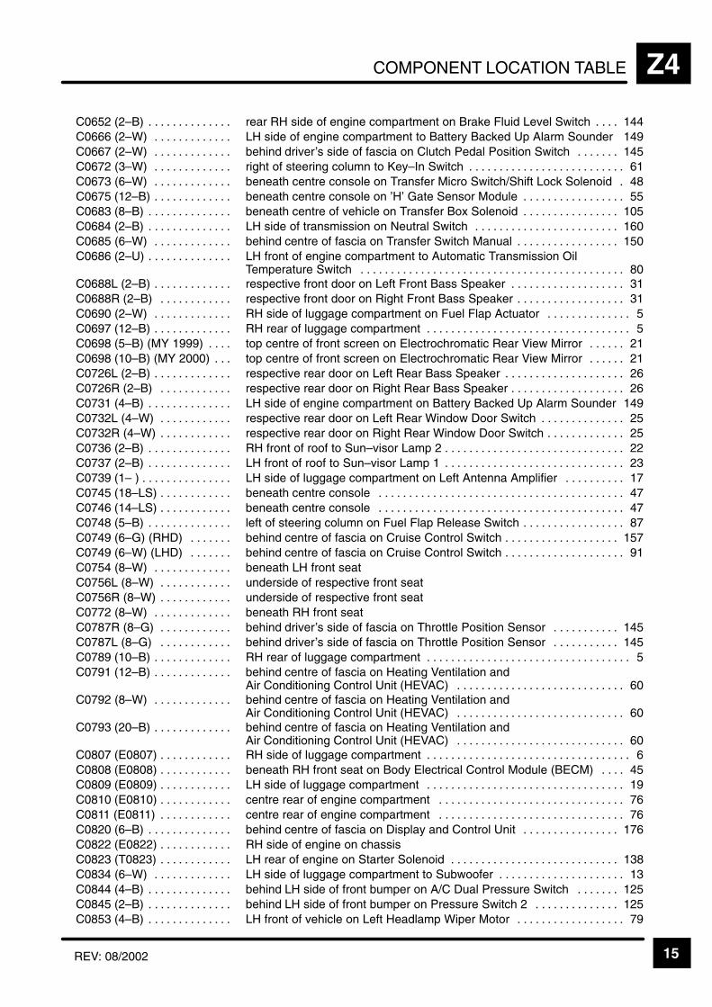
COMPONENT LOCATION TABLE Z4
15REV: 08/2002
ÁÁÁÁÁÁÁÁÁÁÁÁÁÁÁÁÁÁÁÁÁÁ
C0652 (2–B) . . . . . . . . . . . . . . ÁÁÁÁÁÁÁÁÁÁÁÁÁÁÁÁÁÁÁÁÁÁÁÁÁÁÁÁÁÁÁÁÁÁÁÁÁÁÁÁÁÁÁÁÁÁrear RH side of engine compartment on Brake Fluid Level Switch 144. . . .
ÁÁÁÁÁÁÁÁÁÁÁC0666 (2–W) . . . . . . . . . . . . . ÁÁÁÁÁÁÁÁÁÁÁÁÁÁÁÁÁÁÁÁÁÁÁLH side of engine compartment to Battery Backed Up Alarm Sounder 149ÁÁÁÁÁÁÁÁÁÁÁÁÁÁÁÁÁÁÁÁÁÁ
C0667 (2–W) . . . . . . . . . . . . . ÁÁÁÁÁÁÁÁÁÁÁÁÁÁÁÁÁÁÁÁÁÁÁÁÁÁÁÁÁÁÁÁÁÁÁÁÁÁÁÁÁÁÁÁÁÁbehind driver’s side of fascia on Clutch Pedal Position Switch 145. . . . . . .
ÁÁÁÁÁÁÁÁÁÁÁÁÁÁÁÁÁÁÁÁÁÁ
C0672 (3–W) . . . . . . . . . . . . . ÁÁÁÁÁÁÁÁÁÁÁÁÁÁÁÁÁÁÁÁÁÁÁÁÁÁÁÁÁÁÁÁÁÁÁÁÁÁÁÁÁÁÁÁÁÁright of steering column to Key–In Switch 61. . . . . . . . . . . . . . . . . . . . . . . . . .
ÁÁÁÁÁÁÁÁÁÁÁÁÁÁÁÁÁÁÁÁÁÁ
C0673 (6–W) . . . . . . . . . . . . . ÁÁÁÁÁÁÁÁÁÁÁÁÁÁÁÁÁÁÁÁÁÁÁÁÁÁÁÁÁÁÁÁÁÁÁÁÁÁÁÁÁÁÁÁÁÁbeneath centre console on Transfer Micro Switch/Shift Lock Solenoid 48.
ÁÁÁÁÁÁÁÁÁÁÁÁÁÁÁÁÁÁÁÁÁÁ
C0675 (12–B) . . . . . . . . . . . . . ÁÁÁÁÁÁÁÁÁÁÁÁÁÁÁÁÁÁÁÁÁÁÁÁÁÁÁÁÁÁÁÁÁÁÁÁÁÁÁÁÁÁÁÁÁÁbeneath centre console on ’H’ Gate Sensor Module 55. . . . . . . . . . . . . . . . .
ÁÁÁÁÁÁÁÁÁÁÁC0683 (8–B) . . . . . . . . . . . . . . ÁÁÁÁÁÁÁÁÁÁÁÁÁÁÁÁÁÁÁÁÁÁÁbeneath centre of vehicle on Transfer Box Solenoid 105. . . . . . . . . . . . . . . . ÁÁÁÁÁÁÁÁÁÁÁÁÁÁÁÁÁÁÁÁÁÁC0684 (2–B) . . . . . . . . . . . . . .
ÁÁÁÁÁÁÁÁÁÁÁÁÁÁÁÁÁÁÁÁÁÁÁÁÁÁÁÁÁÁÁÁÁÁÁÁÁÁÁÁÁÁÁÁÁÁLH side of transmission on Neutral Switch 160. . . . . . . . . . . . . . . . . . . . . . . . ÁÁÁÁÁÁÁÁÁÁÁ
ÁÁÁÁÁÁÁÁÁÁÁC0685 (6–W) . . . . . . . . . . . . . ÁÁÁÁÁÁÁÁÁÁÁÁÁÁÁÁÁÁÁÁÁÁÁ
ÁÁÁÁÁÁÁÁÁÁÁÁÁÁÁÁÁÁÁÁÁÁÁbehind centre of fascia on Transfer Switch Manual 150. . . . . . . . . . . . . . . . .
ÁÁÁÁÁÁÁÁÁÁÁÁÁÁÁÁÁÁÁÁÁÁÁÁÁÁÁÁÁÁÁÁÁ
C0686 (2–U) . . . . . . . . . . . . . . ÁÁÁÁÁÁÁÁÁÁÁÁÁÁÁÁÁÁÁÁÁÁÁÁÁÁÁÁÁÁÁÁÁÁÁÁÁÁÁÁÁÁÁÁÁÁÁÁÁÁÁÁÁÁÁÁÁÁÁÁÁÁÁÁÁÁÁÁÁ
LH front of engine compartment to Automatic Transmission OilTemperature Switch 80. . . . . . . . . . . . . . . . . . . . . . . . . . . . . . . . . . . . . . . . . . . .
ÁÁÁÁÁÁÁÁÁÁÁC0688L (2–B) . . . . . . . . . . . . . ÁÁÁÁÁÁÁÁÁÁÁÁÁÁÁÁÁÁÁÁÁÁÁrespective front door on Left Front Bass Speaker 31. . . . . . . . . . . . . . . . . . . ÁÁÁÁÁÁÁÁÁÁÁÁÁÁÁÁÁÁÁÁÁÁ
C0688R (2–B) . . . . . . . . . . . . ÁÁÁÁÁÁÁÁÁÁÁÁÁÁÁÁÁÁÁÁÁÁÁÁÁÁÁÁÁÁÁÁÁÁÁÁÁÁÁÁÁÁÁÁÁÁrespective front door on Right Front Bass Speaker 31. . . . . . . . . . . . . . . . . .
ÁÁÁÁÁÁÁÁÁÁÁÁÁÁÁÁÁÁÁÁÁÁ
C0690 (2–W) . . . . . . . . . . . . . ÁÁÁÁÁÁÁÁÁÁÁÁÁÁÁÁÁÁÁÁÁÁÁÁÁÁÁÁÁÁÁÁÁÁÁÁÁÁÁÁÁÁÁÁÁÁRH side of luggage compartment on Fuel Flap Actuator 5. . . . . . . . . . . . . .
ÁÁÁÁÁÁÁÁÁÁÁÁÁÁÁÁÁÁÁÁÁÁ
C0697 (12–B) . . . . . . . . . . . . . ÁÁÁÁÁÁÁÁÁÁÁÁÁÁÁÁÁÁÁÁÁÁÁÁÁÁÁÁÁÁÁÁÁÁÁÁÁÁÁÁÁÁÁÁÁÁRH rear of luggage compartment 5. . . . . . . . . . . . . . . . . . . . . . . . . . . . . . . . . .
ÁÁÁÁÁÁÁÁÁÁÁÁÁÁÁÁÁÁÁÁÁÁ
C0698 (5–B) (MY 1999) . . . . ÁÁÁÁÁÁÁÁÁÁÁÁÁÁÁÁÁÁÁÁÁÁÁÁÁÁÁÁÁÁÁÁÁÁÁÁÁÁÁÁÁÁÁÁÁÁtop centre of front screen on Electrochromatic Rear View Mirror 21. . . . . .
ÁÁÁÁÁÁÁÁÁÁÁC0698 (10–B) (MY 2000) . . . ÁÁÁÁÁÁÁÁÁÁÁÁÁÁÁÁÁÁÁÁÁÁÁtop centre of front screen on Electrochromatic Rear View Mirror 21. . . . . . ÁÁÁÁÁÁÁÁÁÁÁÁÁÁÁÁÁÁÁÁÁÁC0726L (2–B) . . . . . . . . . . . . .
ÁÁÁÁÁÁÁÁÁÁÁÁÁÁÁÁÁÁÁÁÁÁÁÁÁÁÁÁÁÁÁÁÁÁÁÁÁÁÁÁÁÁÁÁÁÁrespective rear door on Left Rear Bass Speaker 26. . . . . . . . . . . . . . . . . . . . ÁÁÁÁÁÁÁÁÁÁÁ
ÁÁÁÁÁÁÁÁÁÁÁC0726R (2–B) . . . . . . . . . . . . ÁÁÁÁÁÁÁÁÁÁÁÁÁÁÁÁÁÁÁÁÁÁÁ
ÁÁÁÁÁÁÁÁÁÁÁÁÁÁÁÁÁÁÁÁÁÁÁrespective rear door on Right Rear Bass Speaker 26. . . . . . . . . . . . . . . . . . .
ÁÁÁÁÁÁÁÁÁÁÁÁÁÁÁÁÁÁÁÁÁÁ
C0731 (4–B) . . . . . . . . . . . . . . ÁÁÁÁÁÁÁÁÁÁÁÁÁÁÁÁÁÁÁÁÁÁÁÁÁÁÁÁÁÁÁÁÁÁÁÁÁÁÁÁÁÁÁÁÁÁLH side of engine compartment on Battery Backed Up Alarm Sounder 149
ÁÁÁÁÁÁÁÁÁÁÁÁÁÁÁÁÁÁÁÁÁÁ
C0732L (4–W) . . . . . . . . . . . . ÁÁÁÁÁÁÁÁÁÁÁÁÁÁÁÁÁÁÁÁÁÁÁÁÁÁÁÁÁÁÁÁÁÁÁÁÁÁÁÁÁÁÁÁÁÁrespective rear door on Left Rear Window Door Switch 25. . . . . . . . . . . . . .
ÁÁÁÁÁÁÁÁÁÁÁÁÁÁÁÁÁÁÁÁÁÁ
C0732R (4–W) . . . . . . . . . . . . ÁÁÁÁÁÁÁÁÁÁÁÁÁÁÁÁÁÁÁÁÁÁÁÁÁÁÁÁÁÁÁÁÁÁÁÁÁÁÁÁÁÁÁÁÁÁrespective rear door on Right Rear Window Door Switch 25. . . . . . . . . . . . .
ÁÁÁÁÁÁÁÁÁÁÁC0736 (2–B) . . . . . . . . . . . . . . ÁÁÁÁÁÁÁÁÁÁÁÁÁÁÁÁÁÁÁÁÁÁÁRH front of roof to Sun–visor Lamp 2 22. . . . . . . . . . . . . . . . . . . . . . . . . . . . . . ÁÁÁÁÁÁÁÁÁÁÁÁÁÁÁÁÁÁÁÁÁÁ
C0737 (2–B) . . . . . . . . . . . . . . ÁÁÁÁÁÁÁÁÁÁÁÁÁÁÁÁÁÁÁÁÁÁÁÁÁÁÁÁÁÁÁÁÁÁÁÁÁÁÁÁÁÁÁÁÁÁLH front of roof to Sun–visor Lamp 1 23. . . . . . . . . . . . . . . . . . . . . . . . . . . . . .
ÁÁÁÁÁÁÁÁÁÁÁÁÁÁÁÁÁÁÁÁÁÁ
C0739 (1– ) . . . . . . . . . . . . . . . ÁÁÁÁÁÁÁÁÁÁÁÁÁÁÁÁÁÁÁÁÁÁÁÁÁÁÁÁÁÁÁÁÁÁÁÁÁÁÁÁÁÁÁÁÁÁLH side of luggage compartment on Left Antenna Amplifier 17. . . . . . . . . .
ÁÁÁÁÁÁÁÁÁÁÁÁÁÁÁÁÁÁÁÁÁÁ
C0745 (18–LS) . . . . . . . . . . . . ÁÁÁÁÁÁÁÁÁÁÁÁÁÁÁÁÁÁÁÁÁÁÁÁÁÁÁÁÁÁÁÁÁÁÁÁÁÁÁÁÁÁÁÁÁÁbeneath centre console 47. . . . . . . . . . . . . . . . . . . . . . . . . . . . . . . . . . . . . . . . .
ÁÁÁÁÁÁÁÁÁÁÁÁÁÁÁÁÁÁÁÁÁÁ
C0746 (14–LS) . . . . . . . . . . . . ÁÁÁÁÁÁÁÁÁÁÁÁÁÁÁÁÁÁÁÁÁÁÁÁÁÁÁÁÁÁÁÁÁÁÁÁÁÁÁÁÁÁÁÁÁÁbeneath centre console 47. . . . . . . . . . . . . . . . . . . . . . . . . . . . . . . . . . . . . . . . .
ÁÁÁÁÁÁÁÁÁÁÁC0748 (5–B) . . . . . . . . . . . . . . ÁÁÁÁÁÁÁÁÁÁÁÁÁÁÁÁÁÁÁÁÁÁÁleft of steering column on Fuel Flap Release Switch 87. . . . . . . . . . . . . . . . . ÁÁÁÁÁÁÁÁÁÁÁÁÁÁÁÁÁÁÁÁÁÁ
C0749 (6–G) (RHD) . . . . . . . ÁÁÁÁÁÁÁÁÁÁÁÁÁÁÁÁÁÁÁÁÁÁÁÁÁÁÁÁÁÁÁÁÁÁÁÁÁÁÁÁÁÁÁÁÁÁbehind centre of fascia on Cruise Control Switch 157. . . . . . . . . . . . . . . . . . .
ÁÁÁÁÁÁÁÁÁÁÁÁÁÁÁÁÁÁÁÁÁÁ
C0749 (6–W) (LHD) . . . . . . . ÁÁÁÁÁÁÁÁÁÁÁÁÁÁÁÁÁÁÁÁÁÁÁÁÁÁÁÁÁÁÁÁÁÁÁÁÁÁÁÁÁÁÁÁÁÁbehind centre of fascia on Cruise Control Switch 91. . . . . . . . . . . . . . . . . . . .
ÁÁÁÁÁÁÁÁÁÁÁÁÁÁÁÁÁÁÁÁÁÁ
C0754 (8–W) . . . . . . . . . . . . . ÁÁÁÁÁÁÁÁÁÁÁÁÁÁÁÁÁÁÁÁÁÁÁÁÁÁÁÁÁÁÁÁÁÁÁÁÁÁÁÁÁÁÁÁÁÁbeneath LH front seat
ÁÁÁÁÁÁÁÁÁÁÁÁÁÁÁÁÁÁÁÁÁÁ
C0756L (8–W) . . . . . . . . . . . . ÁÁÁÁÁÁÁÁÁÁÁÁÁÁÁÁÁÁÁÁÁÁÁÁÁÁÁÁÁÁÁÁÁÁÁÁÁÁÁÁÁÁÁÁÁÁunderside of respective front seat
ÁÁÁÁÁÁÁÁÁÁÁC0756R (8–W) . . . . . . . . . . . . ÁÁÁÁÁÁÁÁÁÁÁÁÁÁÁÁÁÁÁÁÁÁÁunderside of respective front seatÁÁÁÁÁÁÁÁÁÁÁÁÁÁÁÁÁÁÁÁÁÁC0772 (8–W) . . . . . . . . . . . . .
ÁÁÁÁÁÁÁÁÁÁÁÁÁÁÁÁÁÁÁÁÁÁÁÁÁÁÁÁÁÁÁÁÁÁÁÁÁÁÁÁÁÁÁÁÁÁbeneath RH front seatÁÁÁÁÁÁÁÁÁÁÁ
ÁÁÁÁÁÁÁÁÁÁÁC0787R (8–G) . . . . . . . . . . . . ÁÁÁÁÁÁÁÁÁÁÁÁÁÁÁÁÁÁÁÁÁÁÁ
ÁÁÁÁÁÁÁÁÁÁÁÁÁÁÁÁÁÁÁÁÁÁÁbehind driver’s side of fascia on Throttle Position Sensor 145. . . . . . . . . . .
ÁÁÁÁÁÁÁÁÁÁÁÁÁÁÁÁÁÁÁÁÁÁ
C0787L (8–G) . . . . . . . . . . . . ÁÁÁÁÁÁÁÁÁÁÁÁÁÁÁÁÁÁÁÁÁÁÁÁÁÁÁÁÁÁÁÁÁÁÁÁÁÁÁÁÁÁÁÁÁÁbehind driver’s side of fascia on Throttle Position Sensor 145. . . . . . . . . . .
ÁÁÁÁÁÁÁÁÁÁÁÁÁÁÁÁÁÁÁÁÁÁ
C0789 (10–B) . . . . . . . . . . . . . ÁÁÁÁÁÁÁÁÁÁÁÁÁÁÁÁÁÁÁÁÁÁÁÁÁÁÁÁÁÁÁÁÁÁÁÁÁÁÁÁÁÁÁÁÁÁRH rear of luggage compartment 5. . . . . . . . . . . . . . . . . . . . . . . . . . . . . . . . . .
ÁÁÁÁÁÁÁÁÁÁÁÁÁÁÁÁÁÁÁÁÁÁ
C0791 (12–B) . . . . . . . . . . . . . ÁÁÁÁÁÁÁÁÁÁÁÁÁÁÁÁÁÁÁÁÁÁÁÁÁÁÁÁÁÁÁÁÁÁÁÁÁÁÁÁÁÁÁÁÁÁbehind centre of fascia on Heating Ventilation and Air Conditioning Control Unit (HEVAC) 60. . . . . . . . . . . . . . . . . . . . . . . . . . . . ÁÁÁÁÁÁÁÁÁÁÁ
ÁÁÁÁÁÁÁÁÁÁÁÁÁÁÁÁÁÁÁÁÁÁ
C0792 (8–W) . . . . . . . . . . . . . ÁÁÁÁÁÁÁÁÁÁÁÁÁÁÁÁÁÁÁÁÁÁÁÁÁÁÁÁÁÁÁÁÁÁÁÁÁÁÁÁÁÁÁÁÁÁÁÁÁÁÁÁÁÁÁÁÁÁÁÁÁÁÁÁÁÁÁÁÁ
behind centre of fascia on Heating Ventilation and Air Conditioning Control Unit (HEVAC) 60. . . . . . . . . . . . . . . . . . . . . . . . . . . .
ÁÁÁÁÁÁÁÁÁÁÁÁÁÁÁÁÁÁÁÁÁÁ
C0793 (20–B) . . . . . . . . . . . . . ÁÁÁÁÁÁÁÁÁÁÁÁÁÁÁÁÁÁÁÁÁÁÁÁÁÁÁÁÁÁÁÁÁÁÁÁÁÁÁÁÁÁÁÁÁÁbehind centre of fascia on Heating Ventilation and Air Conditioning Control Unit (HEVAC) 60. . . . . . . . . . . . . . . . . . . . . . . . . . . . ÁÁÁÁÁÁÁÁÁÁÁ
ÁÁÁÁÁÁÁÁÁÁÁC0807 (E0807) . . . . . . . . . . . . ÁÁÁÁÁÁÁÁÁÁÁÁÁÁÁÁÁÁÁÁÁÁÁ
ÁÁÁÁÁÁÁÁÁÁÁÁÁÁÁÁÁÁÁÁÁÁÁRH side of luggage compartment 6. . . . . . . . . . . . . . . . . . . . . . . . . . . . . . . . . .
ÁÁÁÁÁÁÁÁÁÁÁÁÁÁÁÁÁÁÁÁÁÁ
C0808 (E0808) . . . . . . . . . . . . ÁÁÁÁÁÁÁÁÁÁÁÁÁÁÁÁÁÁÁÁÁÁÁÁÁÁÁÁÁÁÁÁÁÁÁÁÁÁÁÁÁÁÁÁÁÁbeneath RH front seat on Body Electrical Control Module (BECM) 45. . . .
ÁÁÁÁÁÁÁÁÁÁÁÁÁÁÁÁÁÁÁÁÁÁ
C0809 (E0809) . . . . . . . . . . . . ÁÁÁÁÁÁÁÁÁÁÁÁÁÁÁÁÁÁÁÁÁÁÁÁÁÁÁÁÁÁÁÁÁÁÁÁÁÁÁÁÁÁÁÁÁÁLH side of luggage compartment 19. . . . . . . . . . . . . . . . . . . . . . . . . . . . . . . . .
ÁÁÁÁÁÁÁÁÁÁÁC0810 (E0810) . . . . . . . . . . . . ÁÁÁÁÁÁÁÁÁÁÁÁÁÁÁÁÁÁÁÁÁÁÁcentre rear of engine compartment 76. . . . . . . . . . . . . . . . . . . . . . . . . . . . . . . ÁÁÁÁÁÁÁÁÁÁÁÁÁÁÁÁÁÁÁÁÁÁC0811 (E0811) . . . . . . . . . . . .
ÁÁÁÁÁÁÁÁÁÁÁÁÁÁÁÁÁÁÁÁÁÁÁÁÁÁÁÁÁÁÁÁÁÁÁÁÁÁÁÁÁÁÁÁÁÁcentre rear of engine compartment 76. . . . . . . . . . . . . . . . . . . . . . . . . . . . . . . ÁÁÁÁÁÁÁÁÁÁÁ
ÁÁÁÁÁÁÁÁÁÁÁC0820 (6–B) . . . . . . . . . . . . . . ÁÁÁÁÁÁÁÁÁÁÁÁÁÁÁÁÁÁÁÁÁÁÁ
ÁÁÁÁÁÁÁÁÁÁÁÁÁÁÁÁÁÁÁÁÁÁÁbehind centre of fascia on Display and Control Unit 176. . . . . . . . . . . . . . . .
ÁÁÁÁÁÁÁÁÁÁÁÁÁÁÁÁÁÁÁÁÁÁ
C0822 (E0822) . . . . . . . . . . . . ÁÁÁÁÁÁÁÁÁÁÁÁÁÁÁÁÁÁÁÁÁÁÁÁÁÁÁÁÁÁÁÁÁÁÁÁÁÁÁÁÁÁÁÁÁÁRH side of engine on chassis
ÁÁÁÁÁÁÁÁÁÁÁÁÁÁÁÁÁÁÁÁÁÁ
C0823 (T0823) . . . . . . . . . . . . ÁÁÁÁÁÁÁÁÁÁÁÁÁÁÁÁÁÁÁÁÁÁÁÁÁÁÁÁÁÁÁÁÁÁÁÁÁÁÁÁÁÁÁÁÁÁLH rear of engine on Starter Solenoid 138. . . . . . . . . . . . . . . . . . . . . . . . . . . .
ÁÁÁÁÁÁÁÁÁÁÁÁÁÁÁÁÁÁÁÁÁÁ
C0834 (6–W) . . . . . . . . . . . . . ÁÁÁÁÁÁÁÁÁÁÁÁÁÁÁÁÁÁÁÁÁÁÁÁÁÁÁÁÁÁÁÁÁÁÁÁÁÁÁÁÁÁÁÁÁÁLH side of luggage compartment to Subwoofer 13. . . . . . . . . . . . . . . . . . . . .
ÁÁÁÁÁÁÁÁÁÁÁC0844 (4–B) . . . . . . . . . . . . . . ÁÁÁÁÁÁÁÁÁÁÁÁÁÁÁÁÁÁÁÁÁÁÁbehind LH side of front bumper on A/C Dual Pressure Switch 125. . . . . . . ÁÁÁÁÁÁÁÁÁÁÁÁÁÁÁÁÁÁÁÁÁÁ
C0845 (2–B) . . . . . . . . . . . . . . ÁÁÁÁÁÁÁÁÁÁÁÁÁÁÁÁÁÁÁÁÁÁÁÁÁÁÁÁÁÁÁÁÁÁÁÁÁÁÁÁÁÁÁÁÁÁbehind LH side of front bumper on Pressure Switch 2 125. . . . . . . . . . . . . .
ÁÁÁÁÁÁÁÁÁÁÁÁÁÁÁÁÁÁÁÁÁÁ
C0853 (4–B) . . . . . . . . . . . . . . ÁÁÁÁÁÁÁÁÁÁÁÁÁÁÁÁÁÁÁÁÁÁÁÁÁÁÁÁÁÁÁÁÁÁÁÁÁÁÁÁÁÁÁÁÁÁLH front of vehicle on Left Headlamp Wiper Motor 79. . . . . . . . . . . . . . . . . .
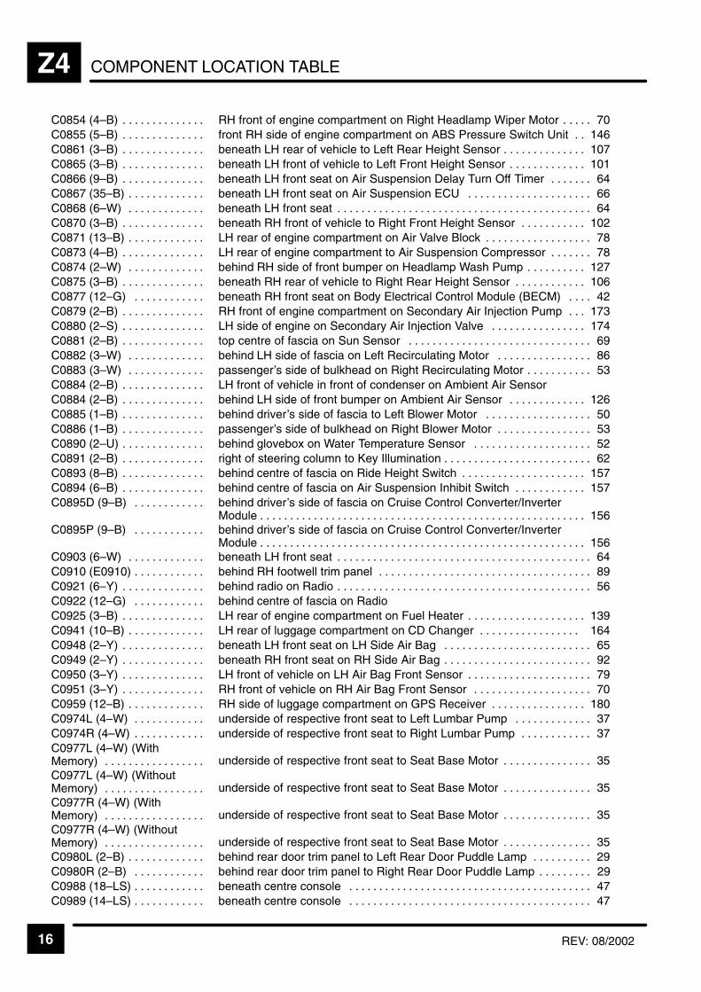
COMPONENT LOCATION TABLEZ4
16 REV: 08/2002
ÁÁÁÁÁÁÁÁÁÁÁÁÁÁÁÁÁÁÁÁ
C0854 (4–B) . . . . . . . . . . . . . . ÁÁÁÁÁÁÁÁÁÁÁÁÁÁÁÁÁÁÁÁÁÁÁÁÁÁÁÁÁÁÁÁÁÁÁÁÁÁÁÁÁÁÁÁÁÁ
RH front of engine compartment on Right Headlamp Wiper Motor 70. . . . .
ÁÁÁÁÁÁÁÁÁÁC0855 (5–B) . . . . . . . . . . . . . . ÁÁÁÁÁÁÁÁÁÁÁÁÁÁÁÁÁÁÁÁÁÁÁfront RH side of engine compartment on ABS Pressure Switch Unit 146. . ÁÁÁÁÁÁÁÁÁÁÁÁÁÁÁÁÁÁÁÁ
C0861 (3–B) . . . . . . . . . . . . . . ÁÁÁÁÁÁÁÁÁÁÁÁÁÁÁÁÁÁÁÁÁÁÁÁÁÁÁÁÁÁÁÁÁÁÁÁÁÁÁÁÁÁÁÁÁÁ
beneath LH rear of vehicle to Left Rear Height Sensor 107. . . . . . . . . . . . . . ÁÁÁÁÁÁÁÁÁÁÁÁÁÁÁÁÁÁÁÁ
C0865 (3–B) . . . . . . . . . . . . . . ÁÁÁÁÁÁÁÁÁÁÁÁÁÁÁÁÁÁÁÁÁÁÁÁÁÁÁÁÁÁÁÁÁÁÁÁÁÁÁÁÁÁÁÁÁÁ
beneath LH front of vehicle to Left Front Height Sensor 101. . . . . . . . . . . . . ÁÁÁÁÁÁÁÁÁÁÁÁÁÁÁÁÁÁÁÁ
C0866 (9–B) . . . . . . . . . . . . . . ÁÁÁÁÁÁÁÁÁÁÁÁÁÁÁÁÁÁÁÁÁÁÁÁÁÁÁÁÁÁÁÁÁÁÁÁÁÁÁÁÁÁÁÁÁÁ
beneath LH front seat on Air Suspension Delay Turn Off Timer 64. . . . . . . ÁÁÁÁÁÁÁÁÁÁÁÁÁÁÁÁÁÁÁÁ
C0867 (35–B) . . . . . . . . . . . . . ÁÁÁÁÁÁÁÁÁÁÁÁÁÁÁÁÁÁÁÁÁÁÁÁÁÁÁÁÁÁÁÁÁÁÁÁÁÁÁÁÁÁÁÁÁÁ
beneath LH front seat on Air Suspension ECU 66. . . . . . . . . . . . . . . . . . . . .
ÁÁÁÁÁÁÁÁÁÁC0868 (6–W) . . . . . . . . . . . . . ÁÁÁÁÁÁÁÁÁÁÁÁÁÁÁÁÁÁÁÁÁÁÁbeneath LH front seat 64. . . . . . . . . . . . . . . . . . . . . . . . . . . . . . . . . . . . . . . . . . . ÁÁÁÁÁÁÁÁÁÁÁÁÁÁÁÁÁÁÁÁC0870 (3–B) . . . . . . . . . . . . . .
ÁÁÁÁÁÁÁÁÁÁÁÁÁÁÁÁÁÁÁÁÁÁÁÁÁÁÁÁÁÁÁÁÁÁÁÁÁÁÁÁÁÁÁÁÁÁbeneath RH front of vehicle to Right Front Height Sensor 102. . . . . . . . . . . ÁÁÁÁÁÁÁÁÁÁ
ÁÁÁÁÁÁÁÁÁÁC0871 (13–B) . . . . . . . . . . . . . ÁÁÁÁÁÁÁÁÁÁÁÁÁÁÁÁÁÁÁÁÁÁÁ
ÁÁÁÁÁÁÁÁÁÁÁÁÁÁÁÁÁÁÁÁÁÁÁLH rear of engine compartment on Air Valve Block 78. . . . . . . . . . . . . . . . . .
ÁÁÁÁÁÁÁÁÁÁÁÁÁÁÁÁÁÁÁÁ
C0873 (4–B) . . . . . . . . . . . . . . ÁÁÁÁÁÁÁÁÁÁÁÁÁÁÁÁÁÁÁÁÁÁÁÁÁÁÁÁÁÁÁÁÁÁÁÁÁÁÁÁÁÁÁÁÁÁ
LH rear of engine compartment to Air Suspension Compressor 78. . . . . . . ÁÁÁÁÁÁÁÁÁÁÁÁÁÁÁÁÁÁÁÁ
C0874 (2–W) . . . . . . . . . . . . . ÁÁÁÁÁÁÁÁÁÁÁÁÁÁÁÁÁÁÁÁÁÁÁÁÁÁÁÁÁÁÁÁÁÁÁÁÁÁÁÁÁÁÁÁÁÁ
behind RH side of front bumper on Headlamp Wash Pump 127. . . . . . . . . .
ÁÁÁÁÁÁÁÁÁÁÁÁÁÁÁÁÁÁÁÁ
C0875 (3–B) . . . . . . . . . . . . . . ÁÁÁÁÁÁÁÁÁÁÁÁÁÁÁÁÁÁÁÁÁÁÁÁÁÁÁÁÁÁÁÁÁÁÁÁÁÁÁÁÁÁÁÁÁÁ
beneath RH rear of vehicle to Right Rear Height Sensor 106. . . . . . . . . . . .
ÁÁÁÁÁÁÁÁÁÁC0877 (12–G) . . . . . . . . . . . . ÁÁÁÁÁÁÁÁÁÁÁÁÁÁÁÁÁÁÁÁÁÁÁbeneath RH front seat on Body Electrical Control Module (BECM) 42. . . . ÁÁÁÁÁÁÁÁÁÁÁÁÁÁÁÁÁÁÁÁ
C0879 (2–B) . . . . . . . . . . . . . . ÁÁÁÁÁÁÁÁÁÁÁÁÁÁÁÁÁÁÁÁÁÁÁÁÁÁÁÁÁÁÁÁÁÁÁÁÁÁÁÁÁÁÁÁÁÁ
RH front of engine compartment on Secondary Air Injection Pump 173. . . ÁÁÁÁÁÁÁÁÁÁÁÁÁÁÁÁÁÁÁÁ
C0880 (2–S) . . . . . . . . . . . . . . ÁÁÁÁÁÁÁÁÁÁÁÁÁÁÁÁÁÁÁÁÁÁÁÁÁÁÁÁÁÁÁÁÁÁÁÁÁÁÁÁÁÁÁÁÁÁ
LH side of engine on Secondary Air Injection Valve 174. . . . . . . . . . . . . . . . ÁÁÁÁÁÁÁÁÁÁÁÁÁÁÁÁÁÁÁÁ
C0881 (2–B) . . . . . . . . . . . . . . ÁÁÁÁÁÁÁÁÁÁÁÁÁÁÁÁÁÁÁÁÁÁÁÁÁÁÁÁÁÁÁÁÁÁÁÁÁÁÁÁÁÁÁÁÁÁ
top centre of fascia on Sun Sensor 69. . . . . . . . . . . . . . . . . . . . . . . . . . . . . . .
ÁÁÁÁÁÁÁÁÁÁÁÁÁÁÁÁÁÁÁÁ
C0882 (3–W) . . . . . . . . . . . . . ÁÁÁÁÁÁÁÁÁÁÁÁÁÁÁÁÁÁÁÁÁÁÁÁÁÁÁÁÁÁÁÁÁÁÁÁÁÁÁÁÁÁÁÁÁÁ
behind LH side of fascia on Left Recirculating Motor 86. . . . . . . . . . . . . . . .
ÁÁÁÁÁÁÁÁÁÁC0883 (3–W) . . . . . . . . . . . . . ÁÁÁÁÁÁÁÁÁÁÁÁÁÁÁÁÁÁÁÁÁÁÁpassenger’s side of bulkhead on Right Recirculating Motor 53. . . . . . . . . . . ÁÁÁÁÁÁÁÁÁÁÁÁÁÁÁÁÁÁÁÁ
C0884 (2–B) . . . . . . . . . . . . . . ÁÁÁÁÁÁÁÁÁÁÁÁÁÁÁÁÁÁÁÁÁÁÁÁÁÁÁÁÁÁÁÁÁÁÁÁÁÁÁÁÁÁÁÁÁÁ
LH front of vehicle in front of condenser on Ambient Air SensorÁÁÁÁÁÁÁÁÁÁÁÁÁÁÁÁÁÁÁÁ
C0884 (2–B) . . . . . . . . . . . . . . ÁÁÁÁÁÁÁÁÁÁÁÁÁÁÁÁÁÁÁÁÁÁÁÁÁÁÁÁÁÁÁÁÁÁÁÁÁÁÁÁÁÁÁÁÁÁ
behind LH side of front bumper on Ambient Air Sensor 126. . . . . . . . . . . . . ÁÁÁÁÁÁÁÁÁÁÁÁÁÁÁÁÁÁÁÁ
C0885 (1–B) . . . . . . . . . . . . . . ÁÁÁÁÁÁÁÁÁÁÁÁÁÁÁÁÁÁÁÁÁÁÁÁÁÁÁÁÁÁÁÁÁÁÁÁÁÁÁÁÁÁÁÁÁÁ
behind driver’s side of fascia to Left Blower Motor 50. . . . . . . . . . . . . . . . . . ÁÁÁÁÁÁÁÁÁÁÁÁÁÁÁÁÁÁÁÁ
C0886 (1–B) . . . . . . . . . . . . . . ÁÁÁÁÁÁÁÁÁÁÁÁÁÁÁÁÁÁÁÁÁÁÁÁÁÁÁÁÁÁÁÁÁÁÁÁÁÁÁÁÁÁÁÁÁÁ
passenger’s side of bulkhead on Right Blower Motor 53. . . . . . . . . . . . . . . .
ÁÁÁÁÁÁÁÁÁÁC0890 (2–U) . . . . . . . . . . . . . . ÁÁÁÁÁÁÁÁÁÁÁÁÁÁÁÁÁÁÁÁÁÁÁbehind glovebox on Water Temperature Sensor 52. . . . . . . . . . . . . . . . . . . . ÁÁÁÁÁÁÁÁÁÁÁÁÁÁÁÁÁÁÁÁC0891 (2–B) . . . . . . . . . . . . . .
ÁÁÁÁÁÁÁÁÁÁÁÁÁÁÁÁÁÁÁÁÁÁÁÁÁÁÁÁÁÁÁÁÁÁÁÁÁÁÁÁÁÁÁÁÁÁright of steering column to Key Illumination 62. . . . . . . . . . . . . . . . . . . . . . . . . ÁÁÁÁÁÁÁÁÁÁ
ÁÁÁÁÁÁÁÁÁÁC0893 (8–B) . . . . . . . . . . . . . . ÁÁÁÁÁÁÁÁÁÁÁÁÁÁÁÁÁÁÁÁÁÁÁ
ÁÁÁÁÁÁÁÁÁÁÁÁÁÁÁÁÁÁÁÁÁÁÁbehind centre of fascia on Ride Height Switch 157. . . . . . . . . . . . . . . . . . . . .
ÁÁÁÁÁÁÁÁÁÁÁÁÁÁÁÁÁÁÁÁ
C0894 (6–B) . . . . . . . . . . . . . . ÁÁÁÁÁÁÁÁÁÁÁÁÁÁÁÁÁÁÁÁÁÁÁÁÁÁÁÁÁÁÁÁÁÁÁÁÁÁÁÁÁÁÁÁÁÁ
behind centre of fascia on Air Suspension Inhibit Switch 157. . . . . . . . . . . . ÁÁÁÁÁÁÁÁÁÁÁÁÁÁÁÁÁÁÁÁ
C0895D (9–B) . . . . . . . . . . . . ÁÁÁÁÁÁÁÁÁÁÁÁÁÁÁÁÁÁÁÁÁÁÁÁÁÁÁÁÁÁÁÁÁÁÁÁÁÁÁÁÁÁÁÁÁÁ
behind driver’s side of fascia on Cruise Control Converter/Inverter Module 156. . . . . . . . . . . . . . . . . . . . . . . . . . . . . . . . . . . . . . . . . . . . . . . . . . . . . . . ÁÁÁÁÁÁÁÁÁÁ
ÁÁÁÁÁÁÁÁÁÁÁÁÁÁÁÁÁÁÁÁ
C0895P (9–B) . . . . . . . . . . . . ÁÁÁÁÁÁÁÁÁÁÁÁÁÁÁÁÁÁÁÁÁÁÁÁÁÁÁÁÁÁÁÁÁÁÁÁÁÁÁÁÁÁÁÁÁÁÁÁÁÁÁÁÁÁÁÁÁÁÁÁÁÁÁÁÁÁÁÁÁ
behind driver’s side of fascia on Cruise Control Converter/Inverter Module 156. . . . . . . . . . . . . . . . . . . . . . . . . . . . . . . . . . . . . . . . . . . . . . . . . . . . . . .
ÁÁÁÁÁÁÁÁÁÁÁÁÁÁÁÁÁÁÁÁ
C0903 (6–W) . . . . . . . . . . . . . ÁÁÁÁÁÁÁÁÁÁÁÁÁÁÁÁÁÁÁÁÁÁÁÁÁÁÁÁÁÁÁÁÁÁÁÁÁÁÁÁÁÁÁÁÁÁ
beneath LH front seat 64. . . . . . . . . . . . . . . . . . . . . . . . . . . . . . . . . . . . . . . . . . .
ÁÁÁÁÁÁÁÁÁÁÁÁÁÁÁÁÁÁÁÁ
C0910 (E0910) . . . . . . . . . . . . ÁÁÁÁÁÁÁÁÁÁÁÁÁÁÁÁÁÁÁÁÁÁÁÁÁÁÁÁÁÁÁÁÁÁÁÁÁÁÁÁÁÁÁÁÁÁ
behind RH footwell trim panel 89. . . . . . . . . . . . . . . . . . . . . . . . . . . . . . . . . . . .
ÁÁÁÁÁÁÁÁÁÁC0921 (6–Y) . . . . . . . . . . . . . . ÁÁÁÁÁÁÁÁÁÁÁÁÁÁÁÁÁÁÁÁÁÁÁbehind radio on Radio 56. . . . . . . . . . . . . . . . . . . . . . . . . . . . . . . . . . . . . . . . . . . ÁÁÁÁÁÁÁÁÁÁÁÁÁÁÁÁÁÁÁÁ
C0922 (12–G) . . . . . . . . . . . . ÁÁÁÁÁÁÁÁÁÁÁÁÁÁÁÁÁÁÁÁÁÁÁÁÁÁÁÁÁÁÁÁÁÁÁÁÁÁÁÁÁÁÁÁÁÁ
behind centre of fascia on RadioÁÁÁÁÁÁÁÁÁÁÁÁÁÁÁÁÁÁÁÁ
C0925 (3–B) . . . . . . . . . . . . . . ÁÁÁÁÁÁÁÁÁÁÁÁÁÁÁÁÁÁÁÁÁÁÁÁÁÁÁÁÁÁÁÁÁÁÁÁÁÁÁÁÁÁÁÁÁÁ
LH rear of engine compartment on Fuel Heater 139. . . . . . . . . . . . . . . . . . . . ÁÁÁÁÁÁÁÁÁÁÁÁÁÁÁÁÁÁÁÁ
C0941 (10–B) . . . . . . . . . . . . . ÁÁÁÁÁÁÁÁÁÁÁÁÁÁÁÁÁÁÁÁÁÁÁÁÁÁÁÁÁÁÁÁÁÁÁÁÁÁÁÁÁÁÁÁÁÁ
LH rear of luggage compartment on CD Changer 164. . . . . . . . . . . . . . . . .
ÁÁÁÁÁÁÁÁÁÁÁÁÁÁÁÁÁÁÁÁ
C0948 (2–Y) . . . . . . . . . . . . . . ÁÁÁÁÁÁÁÁÁÁÁÁÁÁÁÁÁÁÁÁÁÁÁÁÁÁÁÁÁÁÁÁÁÁÁÁÁÁÁÁÁÁÁÁÁÁ
beneath LH front seat on LH Side Air Bag 65. . . . . . . . . . . . . . . . . . . . . . . . .
ÁÁÁÁÁÁÁÁÁÁC0949 (2–Y) . . . . . . . . . . . . . . ÁÁÁÁÁÁÁÁÁÁÁÁÁÁÁÁÁÁÁÁÁÁÁbeneath RH front seat on RH Side Air Bag 92. . . . . . . . . . . . . . . . . . . . . . . . . ÁÁÁÁÁÁÁÁÁÁÁÁÁÁÁÁÁÁÁÁ
C0950 (3–Y) . . . . . . . . . . . . . . ÁÁÁÁÁÁÁÁÁÁÁÁÁÁÁÁÁÁÁÁÁÁÁÁÁÁÁÁÁÁÁÁÁÁÁÁÁÁÁÁÁÁÁÁÁÁ
LH front of vehicle on LH Air Bag Front Sensor 79. . . . . . . . . . . . . . . . . . . . . ÁÁÁÁÁÁÁÁÁÁÁÁÁÁÁÁÁÁÁÁ
C0951 (3–Y) . . . . . . . . . . . . . . ÁÁÁÁÁÁÁÁÁÁÁÁÁÁÁÁÁÁÁÁÁÁÁÁÁÁÁÁÁÁÁÁÁÁÁÁÁÁÁÁÁÁÁÁÁÁ
RH front of vehicle on RH Air Bag Front Sensor 70. . . . . . . . . . . . . . . . . . . . ÁÁÁÁÁÁÁÁÁÁÁÁÁÁÁÁÁÁÁÁ
C0959 (12–B) . . . . . . . . . . . . . ÁÁÁÁÁÁÁÁÁÁÁÁÁÁÁÁÁÁÁÁÁÁÁÁÁÁÁÁÁÁÁÁÁÁÁÁÁÁÁÁÁÁÁÁÁÁ
RH side of luggage compartment on GPS Receiver 180. . . . . . . . . . . . . . . . ÁÁÁÁÁÁÁÁÁÁÁÁÁÁÁÁÁÁÁÁ
C0974L (4–W) . . . . . . . . . . . . ÁÁÁÁÁÁÁÁÁÁÁÁÁÁÁÁÁÁÁÁÁÁÁÁÁÁÁÁÁÁÁÁÁÁÁÁÁÁÁÁÁÁÁÁÁÁ
underside of respective front seat to Left Lumbar Pump 37. . . . . . . . . . . . .
ÁÁÁÁÁÁÁÁÁÁC0974R (4–W) . . . . . . . . . . . . ÁÁÁÁÁÁÁÁÁÁÁÁÁÁÁÁÁÁÁÁÁÁÁunderside of respective front seat to Right Lumbar Pump 37. . . . . . . . . . . . ÁÁÁÁÁÁÁÁÁÁÁÁÁÁÁÁÁÁÁÁÁÁÁÁÁÁÁÁÁÁ
C0977L (4–W) (WithMemory) . . . . . . . . . . . . . . . . .
ÁÁÁÁÁÁÁÁÁÁÁÁÁÁÁÁÁÁÁÁÁÁÁÁÁÁÁÁÁÁÁÁÁÁÁÁÁÁÁÁÁÁÁÁÁÁÁÁÁÁÁÁÁÁÁÁÁÁÁÁÁÁÁÁÁÁÁÁÁ
underside of respective front seat to Seat Base Motor 35. . . . . . . . . . . . . . . ÁÁÁÁÁÁÁÁÁÁÁÁÁÁÁÁÁÁÁÁ
C0977L (4–W) (WithoutMemory) . . . . . . . . . . . . . . . . .
ÁÁÁÁÁÁÁÁÁÁÁÁÁÁÁÁÁÁÁÁÁÁÁÁÁÁÁÁÁÁÁÁÁÁÁÁÁÁÁÁÁÁÁÁÁÁunderside of respective front seat to Seat Base Motor 35. . . . . . . . . . . . . . . ÁÁÁÁÁÁÁÁÁÁ
ÁÁÁÁÁÁÁÁÁÁÁÁÁÁÁÁÁÁÁÁ
C0977R (4–W) (WithMemory) . . . . . . . . . . . . . . . . .
ÁÁÁÁÁÁÁÁÁÁÁÁÁÁÁÁÁÁÁÁÁÁÁÁÁÁÁÁÁÁÁÁÁÁÁÁÁÁÁÁÁÁÁÁÁÁÁÁÁÁÁÁÁÁÁÁÁÁÁÁÁÁÁÁÁÁÁÁÁ
underside of respective front seat to Seat Base Motor 35. . . . . . . . . . . . . . . ÁÁÁÁÁÁÁÁÁÁÁÁÁÁÁÁÁÁÁÁ
C0977R (4–W) (WithoutMemory) . . . . . . . . . . . . . . . . .
ÁÁÁÁÁÁÁÁÁÁÁÁÁÁÁÁÁÁÁÁÁÁÁÁÁÁÁÁÁÁÁÁÁÁÁÁÁÁÁÁÁÁÁÁÁÁunderside of respective front seat to Seat Base Motor 35. . . . . . . . . . . . . . . ÁÁÁÁÁÁÁÁÁÁ
ÁÁÁÁÁÁÁÁÁÁC0980L (2–B) . . . . . . . . . . . . . ÁÁÁÁÁÁÁÁÁÁÁÁÁÁÁÁÁÁÁÁÁÁÁÁÁÁÁÁÁÁÁÁÁÁÁÁÁÁÁÁÁÁÁÁÁÁbehind rear door trim panel to Left Rear Door Puddle Lamp 29. . . . . . . . . . ÁÁÁÁÁÁÁÁÁÁ
ÁÁÁÁÁÁÁÁÁÁC0980R (2–B) . . . . . . . . . . . . ÁÁÁÁÁÁÁÁÁÁÁÁÁÁÁÁÁÁÁÁÁÁÁ
ÁÁÁÁÁÁÁÁÁÁÁÁÁÁÁÁÁÁÁÁÁÁÁbehind rear door trim panel to Right Rear Door Puddle Lamp 29. . . . . . . . .
ÁÁÁÁÁÁÁÁÁÁÁÁÁÁÁÁÁÁÁÁ
C0988 (18–LS) . . . . . . . . . . . . ÁÁÁÁÁÁÁÁÁÁÁÁÁÁÁÁÁÁÁÁÁÁÁÁÁÁÁÁÁÁÁÁÁÁÁÁÁÁÁÁÁÁÁÁÁÁ
beneath centre console 47. . . . . . . . . . . . . . . . . . . . . . . . . . . . . . . . . . . . . . . . . ÁÁÁÁÁÁÁÁÁÁÁÁÁÁÁÁÁÁÁÁ
C0989 (14–LS) . . . . . . . . . . . . ÁÁÁÁÁÁÁÁÁÁÁÁÁÁÁÁÁÁÁÁÁÁÁÁÁÁÁÁÁÁÁÁÁÁÁÁÁÁÁÁÁÁÁÁÁÁ
beneath centre console 47. . . . . . . . . . . . . . . . . . . . . . . . . . . . . . . . . . . . . . . . .
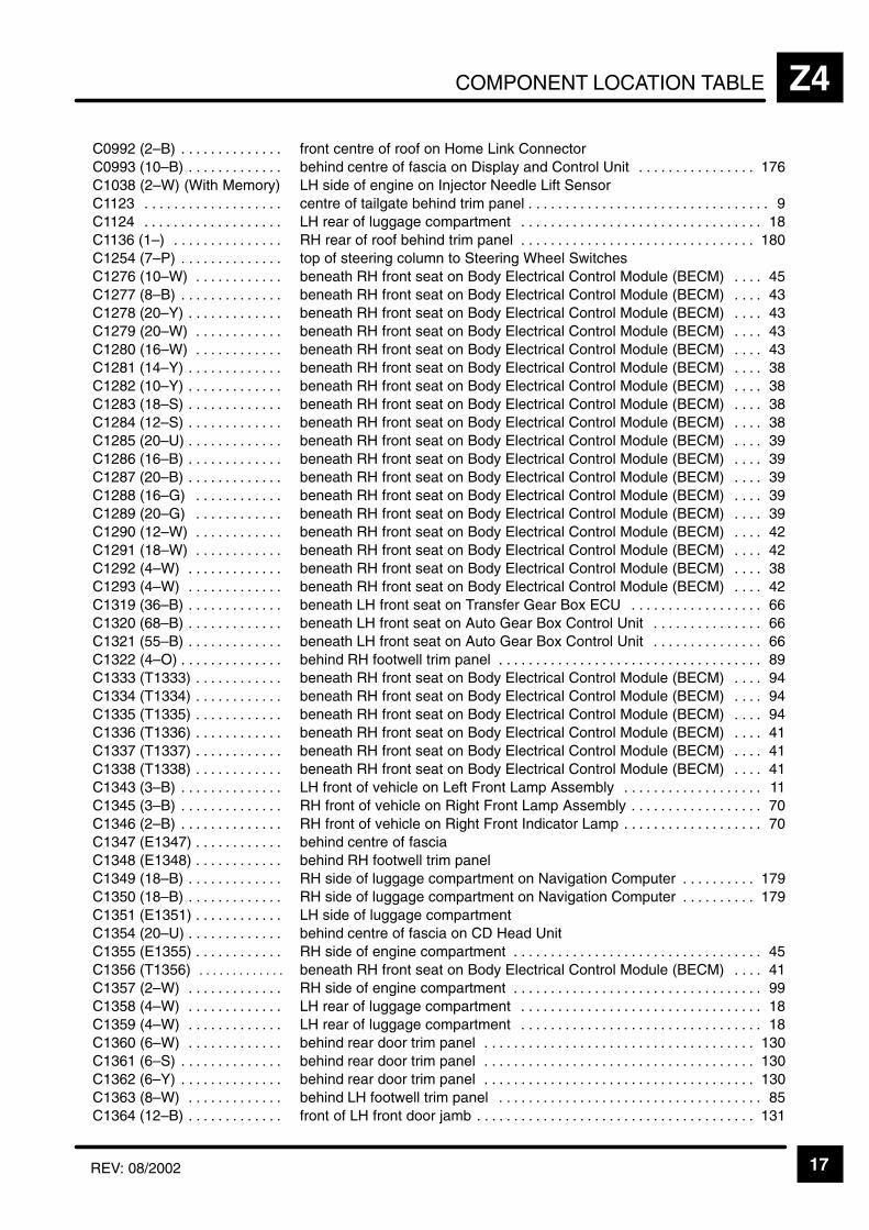
COMPONENT LOCATION TABLE Z4
17REV: 08/2002
ÁÁÁÁÁÁÁÁÁÁÁÁÁÁÁÁÁÁÁÁÁÁ
C0992 (2–B) . . . . . . . . . . . . . . ÁÁÁÁÁÁÁÁÁÁÁÁÁÁÁÁÁÁÁÁÁÁÁÁÁÁÁÁÁÁÁÁÁÁÁÁÁÁÁÁÁÁÁÁÁÁfront centre of roof on Home Link Connector
ÁÁÁÁÁÁÁÁÁÁÁC0993 (10–B) . . . . . . . . . . . . . ÁÁÁÁÁÁÁÁÁÁÁÁÁÁÁÁÁÁÁÁÁÁÁbehind centre of fascia on Display and Control Unit 176. . . . . . . . . . . . . . . . ÁÁÁÁÁÁÁÁÁÁÁÁÁÁÁÁÁÁÁÁÁÁ
C1038 (2–W) (With Memory)ÁÁÁÁÁÁÁÁÁÁÁÁÁÁÁÁÁÁÁÁÁÁÁÁÁÁÁÁÁÁÁÁÁÁÁÁÁÁÁÁÁÁÁÁÁÁLH side of engine on Injector Needle Lift Sensor
ÁÁÁÁÁÁÁÁÁÁÁÁÁÁÁÁÁÁÁÁÁÁ
C1123 . . . . . . . . . . . . . . . . . . . ÁÁÁÁÁÁÁÁÁÁÁÁÁÁÁÁÁÁÁÁÁÁÁÁÁÁÁÁÁÁÁÁÁÁÁÁÁÁÁÁÁÁÁÁÁÁcentre of tailgate behind trim panel 9. . . . . . . . . . . . . . . . . . . . . . . . . . . . . . . . .
ÁÁÁÁÁÁÁÁÁÁÁÁÁÁÁÁÁÁÁÁÁÁ
C1124 . . . . . . . . . . . . . . . . . . . ÁÁÁÁÁÁÁÁÁÁÁÁÁÁÁÁÁÁÁÁÁÁÁÁÁÁÁÁÁÁÁÁÁÁÁÁÁÁÁÁÁÁÁÁÁÁLH rear of luggage compartment 18. . . . . . . . . . . . . . . . . . . . . . . . . . . . . . . . .
ÁÁÁÁÁÁÁÁÁÁÁÁÁÁÁÁÁÁÁÁÁÁ
C1136 (1–) . . . . . . . . . . . . . . . ÁÁÁÁÁÁÁÁÁÁÁÁÁÁÁÁÁÁÁÁÁÁÁÁÁÁÁÁÁÁÁÁÁÁÁÁÁÁÁÁÁÁÁÁÁÁRH rear of roof behind trim panel 180. . . . . . . . . . . . . . . . . . . . . . . . . . . . . . . .
ÁÁÁÁÁÁÁÁÁÁÁC1254 (7–P) . . . . . . . . . . . . . . ÁÁÁÁÁÁÁÁÁÁÁÁÁÁÁÁÁÁÁÁÁÁÁtop of steering column to Steering Wheel SwitchesÁÁÁÁÁÁÁÁÁÁÁÁÁÁÁÁÁÁÁÁÁÁC1276 (10–W) . . . . . . . . . . . .
ÁÁÁÁÁÁÁÁÁÁÁÁÁÁÁÁÁÁÁÁÁÁÁÁÁÁÁÁÁÁÁÁÁÁÁÁÁÁÁÁÁÁÁÁÁÁbeneath RH front seat on Body Electrical Control Module (BECM) 45. . . . ÁÁÁÁÁÁÁÁÁÁÁ
ÁÁÁÁÁÁÁÁÁÁÁC1277 (8–B) . . . . . . . . . . . . . . ÁÁÁÁÁÁÁÁÁÁÁÁÁÁÁÁÁÁÁÁÁÁÁ
ÁÁÁÁÁÁÁÁÁÁÁÁÁÁÁÁÁÁÁÁÁÁÁbeneath RH front seat on Body Electrical Control Module (BECM) 43. . . .
ÁÁÁÁÁÁÁÁÁÁÁÁÁÁÁÁÁÁÁÁÁÁ
C1278 (20–Y) . . . . . . . . . . . . . ÁÁÁÁÁÁÁÁÁÁÁÁÁÁÁÁÁÁÁÁÁÁÁÁÁÁÁÁÁÁÁÁÁÁÁÁÁÁÁÁÁÁÁÁÁÁbeneath RH front seat on Body Electrical Control Module (BECM) 43. . . .
ÁÁÁÁÁÁÁÁÁÁÁÁÁÁÁÁÁÁÁÁÁÁ
C1279 (20–W) . . . . . . . . . . . . ÁÁÁÁÁÁÁÁÁÁÁÁÁÁÁÁÁÁÁÁÁÁÁÁÁÁÁÁÁÁÁÁÁÁÁÁÁÁÁÁÁÁÁÁÁÁbeneath RH front seat on Body Electrical Control Module (BECM) 43. . . .
ÁÁÁÁÁÁÁÁÁÁÁÁÁÁÁÁÁÁÁÁÁÁ
C1280 (16–W) . . . . . . . . . . . . ÁÁÁÁÁÁÁÁÁÁÁÁÁÁÁÁÁÁÁÁÁÁÁÁÁÁÁÁÁÁÁÁÁÁÁÁÁÁÁÁÁÁÁÁÁÁbeneath RH front seat on Body Electrical Control Module (BECM) 43. . . .
ÁÁÁÁÁÁÁÁÁÁÁC1281 (14–Y) . . . . . . . . . . . . . ÁÁÁÁÁÁÁÁÁÁÁÁÁÁÁÁÁÁÁÁÁÁÁbeneath RH front seat on Body Electrical Control Module (BECM) 38. . . . ÁÁÁÁÁÁÁÁÁÁÁÁÁÁÁÁÁÁÁÁÁÁ
C1282 (10–Y) . . . . . . . . . . . . . ÁÁÁÁÁÁÁÁÁÁÁÁÁÁÁÁÁÁÁÁÁÁÁÁÁÁÁÁÁÁÁÁÁÁÁÁÁÁÁÁÁÁÁÁÁÁbeneath RH front seat on Body Electrical Control Module (BECM) 38. . . .
ÁÁÁÁÁÁÁÁÁÁÁÁÁÁÁÁÁÁÁÁÁÁ
C1283 (18–S) . . . . . . . . . . . . . ÁÁÁÁÁÁÁÁÁÁÁÁÁÁÁÁÁÁÁÁÁÁÁÁÁÁÁÁÁÁÁÁÁÁÁÁÁÁÁÁÁÁÁÁÁÁbeneath RH front seat on Body Electrical Control Module (BECM) 38. . . .
ÁÁÁÁÁÁÁÁÁÁÁÁÁÁÁÁÁÁÁÁÁÁ
C1284 (12–S) . . . . . . . . . . . . . ÁÁÁÁÁÁÁÁÁÁÁÁÁÁÁÁÁÁÁÁÁÁÁÁÁÁÁÁÁÁÁÁÁÁÁÁÁÁÁÁÁÁÁÁÁÁbeneath RH front seat on Body Electrical Control Module (BECM) 38. . . .
ÁÁÁÁÁÁÁÁÁÁÁÁÁÁÁÁÁÁÁÁÁÁ
C1285 (20–U) . . . . . . . . . . . . . ÁÁÁÁÁÁÁÁÁÁÁÁÁÁÁÁÁÁÁÁÁÁÁÁÁÁÁÁÁÁÁÁÁÁÁÁÁÁÁÁÁÁÁÁÁÁbeneath RH front seat on Body Electrical Control Module (BECM) 39. . . .
ÁÁÁÁÁÁÁÁÁÁÁC1286 (16–B) . . . . . . . . . . . . . ÁÁÁÁÁÁÁÁÁÁÁÁÁÁÁÁÁÁÁÁÁÁÁbeneath RH front seat on Body Electrical Control Module (BECM) 39. . . . ÁÁÁÁÁÁÁÁÁÁÁÁÁÁÁÁÁÁÁÁÁÁ
C1287 (20–B) . . . . . . . . . . . . . ÁÁÁÁÁÁÁÁÁÁÁÁÁÁÁÁÁÁÁÁÁÁÁÁÁÁÁÁÁÁÁÁÁÁÁÁÁÁÁÁÁÁÁÁÁÁbeneath RH front seat on Body Electrical Control Module (BECM) 39. . . .
ÁÁÁÁÁÁÁÁÁÁÁÁÁÁÁÁÁÁÁÁÁÁ
C1288 (16–G) . . . . . . . . . . . . ÁÁÁÁÁÁÁÁÁÁÁÁÁÁÁÁÁÁÁÁÁÁÁÁÁÁÁÁÁÁÁÁÁÁÁÁÁÁÁÁÁÁÁÁÁÁbeneath RH front seat on Body Electrical Control Module (BECM) 39. . . .
ÁÁÁÁÁÁÁÁÁÁÁÁÁÁÁÁÁÁÁÁÁÁ
C1289 (20–G) . . . . . . . . . . . . ÁÁÁÁÁÁÁÁÁÁÁÁÁÁÁÁÁÁÁÁÁÁÁÁÁÁÁÁÁÁÁÁÁÁÁÁÁÁÁÁÁÁÁÁÁÁbeneath RH front seat on Body Electrical Control Module (BECM) 39. . . .
ÁÁÁÁÁÁÁÁÁÁÁÁÁÁÁÁÁÁÁÁÁÁ
C1290 (12–W) . . . . . . . . . . . . ÁÁÁÁÁÁÁÁÁÁÁÁÁÁÁÁÁÁÁÁÁÁÁÁÁÁÁÁÁÁÁÁÁÁÁÁÁÁÁÁÁÁÁÁÁÁbeneath RH front seat on Body Electrical Control Module (BECM) 42. . . .
ÁÁÁÁÁÁÁÁÁÁÁC1291 (18–W) . . . . . . . . . . . . ÁÁÁÁÁÁÁÁÁÁÁÁÁÁÁÁÁÁÁÁÁÁÁbeneath RH front seat on Body Electrical Control Module (BECM) 42. . . . ÁÁÁÁÁÁÁÁÁÁÁÁÁÁÁÁÁÁÁÁÁÁC1292 (4–W) . . . . . . . . . . . . .
ÁÁÁÁÁÁÁÁÁÁÁÁÁÁÁÁÁÁÁÁÁÁÁÁÁÁÁÁÁÁÁÁÁÁÁÁÁÁÁÁÁÁÁÁÁÁbeneath RH front seat on Body Electrical Control Module (BECM) 38. . . . ÁÁÁÁÁÁÁÁÁÁÁ
ÁÁÁÁÁÁÁÁÁÁÁC1293 (4–W) . . . . . . . . . . . . . ÁÁÁÁÁÁÁÁÁÁÁÁÁÁÁÁÁÁÁÁÁÁÁ
ÁÁÁÁÁÁÁÁÁÁÁÁÁÁÁÁÁÁÁÁÁÁÁbeneath RH front seat on Body Electrical Control Module (BECM) 42. . . .
ÁÁÁÁÁÁÁÁÁÁÁÁÁÁÁÁÁÁÁÁÁÁ
C1319 (36–B) . . . . . . . . . . . . . ÁÁÁÁÁÁÁÁÁÁÁÁÁÁÁÁÁÁÁÁÁÁÁÁÁÁÁÁÁÁÁÁÁÁÁÁÁÁÁÁÁÁÁÁÁÁbeneath LH front seat on Transfer Gear Box ECU 66. . . . . . . . . . . . . . . . . .
ÁÁÁÁÁÁÁÁÁÁÁÁÁÁÁÁÁÁÁÁÁÁ
C1320 (68–B) . . . . . . . . . . . . . ÁÁÁÁÁÁÁÁÁÁÁÁÁÁÁÁÁÁÁÁÁÁÁÁÁÁÁÁÁÁÁÁÁÁÁÁÁÁÁÁÁÁÁÁÁÁbeneath LH front seat on Auto Gear Box Control Unit 66. . . . . . . . . . . . . . .
ÁÁÁÁÁÁÁÁÁÁÁÁÁÁÁÁÁÁÁÁÁÁ
C1321 (55–B) . . . . . . . . . . . . . ÁÁÁÁÁÁÁÁÁÁÁÁÁÁÁÁÁÁÁÁÁÁÁÁÁÁÁÁÁÁÁÁÁÁÁÁÁÁÁÁÁÁÁÁÁÁbeneath LH front seat on Auto Gear Box Control Unit 66. . . . . . . . . . . . . . .
ÁÁÁÁÁÁÁÁÁÁÁC1322 (4–O) . . . . . . . . . . . . . . ÁÁÁÁÁÁÁÁÁÁÁÁÁÁÁÁÁÁÁÁÁÁÁbehind RH footwell trim panel 89. . . . . . . . . . . . . . . . . . . . . . . . . . . . . . . . . . . . ÁÁÁÁÁÁÁÁÁÁÁÁÁÁÁÁÁÁÁÁÁÁ
C1333 (T1333) . . . . . . . . . . . . ÁÁÁÁÁÁÁÁÁÁÁÁÁÁÁÁÁÁÁÁÁÁÁÁÁÁÁÁÁÁÁÁÁÁÁÁÁÁÁÁÁÁÁÁÁÁbeneath RH front seat on Body Electrical Control Module (BECM) 94. . . .
ÁÁÁÁÁÁÁÁÁÁÁÁÁÁÁÁÁÁÁÁÁÁ
C1334 (T1334) . . . . . . . . . . . . ÁÁÁÁÁÁÁÁÁÁÁÁÁÁÁÁÁÁÁÁÁÁÁÁÁÁÁÁÁÁÁÁÁÁÁÁÁÁÁÁÁÁÁÁÁÁbeneath RH front seat on Body Electrical Control Module (BECM) 94. . . .
ÁÁÁÁÁÁÁÁÁÁÁÁÁÁÁÁÁÁÁÁÁÁ
C1335 (T1335) . . . . . . . . . . . . ÁÁÁÁÁÁÁÁÁÁÁÁÁÁÁÁÁÁÁÁÁÁÁÁÁÁÁÁÁÁÁÁÁÁÁÁÁÁÁÁÁÁÁÁÁÁbeneath RH front seat on Body Electrical Control Module (BECM) 94. . . .
ÁÁÁÁÁÁÁÁÁÁÁÁÁÁÁÁÁÁÁÁÁÁ
C1336 (T1336) . . . . . . . . . . . . ÁÁÁÁÁÁÁÁÁÁÁÁÁÁÁÁÁÁÁÁÁÁÁÁÁÁÁÁÁÁÁÁÁÁÁÁÁÁÁÁÁÁÁÁÁÁbeneath RH front seat on Body Electrical Control Module (BECM) 41. . . .
ÁÁÁÁÁÁÁÁÁÁÁC1337 (T1337) . . . . . . . . . . . . ÁÁÁÁÁÁÁÁÁÁÁÁÁÁÁÁÁÁÁÁÁÁÁbeneath RH front seat on Body Electrical Control Module (BECM) 41. . . . ÁÁÁÁÁÁÁÁÁÁÁÁÁÁÁÁÁÁÁÁÁÁ
C1338 (T1338) . . . . . . . . . . . . ÁÁÁÁÁÁÁÁÁÁÁÁÁÁÁÁÁÁÁÁÁÁÁÁÁÁÁÁÁÁÁÁÁÁÁÁÁÁÁÁÁÁÁÁÁÁbeneath RH front seat on Body Electrical Control Module (BECM) 41. . . .
ÁÁÁÁÁÁÁÁÁÁÁÁÁÁÁÁÁÁÁÁÁÁ
C1343 (3–B) . . . . . . . . . . . . . . ÁÁÁÁÁÁÁÁÁÁÁÁÁÁÁÁÁÁÁÁÁÁÁÁÁÁÁÁÁÁÁÁÁÁÁÁÁÁÁÁÁÁÁÁÁÁLH front of vehicle on Left Front Lamp Assembly 11. . . . . . . . . . . . . . . . . . .
ÁÁÁÁÁÁÁÁÁÁÁÁÁÁÁÁÁÁÁÁÁÁ
C1345 (3–B) . . . . . . . . . . . . . . ÁÁÁÁÁÁÁÁÁÁÁÁÁÁÁÁÁÁÁÁÁÁÁÁÁÁÁÁÁÁÁÁÁÁÁÁÁÁÁÁÁÁÁÁÁÁRH front of vehicle on Right Front Lamp Assembly 70. . . . . . . . . . . . . . . . . .
ÁÁÁÁÁÁÁÁÁÁÁÁÁÁÁÁÁÁÁÁÁÁ
C1346 (2–B) . . . . . . . . . . . . . . ÁÁÁÁÁÁÁÁÁÁÁÁÁÁÁÁÁÁÁÁÁÁÁÁÁÁÁÁÁÁÁÁÁÁÁÁÁÁÁÁÁÁÁÁÁÁRH front of vehicle on Right Front Indicator Lamp 70. . . . . . . . . . . . . . . . . . .
ÁÁÁÁÁÁÁÁÁÁÁC1347 (E1347) . . . . . . . . . . . . ÁÁÁÁÁÁÁÁÁÁÁÁÁÁÁÁÁÁÁÁÁÁÁbehind centre of fasciaÁÁÁÁÁÁÁÁÁÁÁÁÁÁÁÁÁÁÁÁÁÁC1348 (E1348) . . . . . . . . . . . .
ÁÁÁÁÁÁÁÁÁÁÁÁÁÁÁÁÁÁÁÁÁÁÁÁÁÁÁÁÁÁÁÁÁÁÁÁÁÁÁÁÁÁÁÁÁÁbehind RH footwell trim panelÁÁÁÁÁÁÁÁÁÁÁ
ÁÁÁÁÁÁÁÁÁÁÁC1349 (18–B) . . . . . . . . . . . . . ÁÁÁÁÁÁÁÁÁÁÁÁÁÁÁÁÁÁÁÁÁÁÁ
ÁÁÁÁÁÁÁÁÁÁÁÁÁÁÁÁÁÁÁÁÁÁÁRH side of luggage compartment on Navigation Computer 179. . . . . . . . . .
ÁÁÁÁÁÁÁÁÁÁÁÁÁÁÁÁÁÁÁÁÁÁ
C1350 (18–B) . . . . . . . . . . . . . ÁÁÁÁÁÁÁÁÁÁÁÁÁÁÁÁÁÁÁÁÁÁÁÁÁÁÁÁÁÁÁÁÁÁÁÁÁÁÁÁÁÁÁÁÁÁRH side of luggage compartment on Navigation Computer 179. . . . . . . . . .
ÁÁÁÁÁÁÁÁÁÁÁÁÁÁÁÁÁÁÁÁÁÁ
C1351 (E1351) . . . . . . . . . . . . ÁÁÁÁÁÁÁÁÁÁÁÁÁÁÁÁÁÁÁÁÁÁÁÁÁÁÁÁÁÁÁÁÁÁÁÁÁÁÁÁÁÁÁÁÁÁLH side of luggage compartment
ÁÁÁÁÁÁÁÁÁÁÁÁÁÁÁÁÁÁÁÁÁÁ
C1354 (20–U) . . . . . . . . . . . . . ÁÁÁÁÁÁÁÁÁÁÁÁÁÁÁÁÁÁÁÁÁÁÁÁÁÁÁÁÁÁÁÁÁÁÁÁÁÁÁÁÁÁÁÁÁÁbehind centre of fascia on CD Head Unit
ÁÁÁÁÁÁÁÁÁÁÁC1355 (E1355) . . . . . . . . . . . . ÁÁÁÁÁÁÁÁÁÁÁÁÁÁÁÁÁÁÁÁÁÁÁRH side of engine compartment 45. . . . . . . . . . . . . . . . . . . . . . . . . . . . . . . . . . ÁÁÁÁÁÁÁÁÁÁÁÁÁÁÁÁÁÁÁÁÁÁ
C1356 (T1356) . . . . . . . . . . . . . ÁÁÁÁÁÁÁÁÁÁÁÁÁÁÁÁÁÁÁÁÁÁÁÁÁÁÁÁÁÁÁÁÁÁÁÁÁÁÁÁÁÁÁÁÁÁbeneath RH front seat on Body Electrical Control Module (BECM) 41. . . .
ÁÁÁÁÁÁÁÁÁÁÁÁÁÁÁÁÁÁÁÁÁÁ
C1357 (2–W) . . . . . . . . . . . . . ÁÁÁÁÁÁÁÁÁÁÁÁÁÁÁÁÁÁÁÁÁÁÁÁÁÁÁÁÁÁÁÁÁÁÁÁÁÁÁÁÁÁÁÁÁÁRH side of engine compartment 99. . . . . . . . . . . . . . . . . . . . . . . . . . . . . . . . . .
ÁÁÁÁÁÁÁÁÁÁÁÁÁÁÁÁÁÁÁÁÁÁ
C1358 (4–W) . . . . . . . . . . . . . ÁÁÁÁÁÁÁÁÁÁÁÁÁÁÁÁÁÁÁÁÁÁÁÁÁÁÁÁÁÁÁÁÁÁÁÁÁÁÁÁÁÁÁÁÁÁLH rear of luggage compartment 18. . . . . . . . . . . . . . . . . . . . . . . . . . . . . . . . .
ÁÁÁÁÁÁÁÁÁÁÁÁÁÁÁÁÁÁÁÁÁÁ
C1359 (4–W) . . . . . . . . . . . . . ÁÁÁÁÁÁÁÁÁÁÁÁÁÁÁÁÁÁÁÁÁÁÁÁÁÁÁÁÁÁÁÁÁÁÁÁÁÁÁÁÁÁÁÁÁÁLH rear of luggage compartment 18. . . . . . . . . . . . . . . . . . . . . . . . . . . . . . . . .
ÁÁÁÁÁÁÁÁÁÁÁC1360 (6–W) . . . . . . . . . . . . . ÁÁÁÁÁÁÁÁÁÁÁÁÁÁÁÁÁÁÁÁÁÁÁbehind rear door trim panel 130. . . . . . . . . . . . . . . . . . . . . . . . . . . . . . . . . . . . . ÁÁÁÁÁÁÁÁÁÁÁÁÁÁÁÁÁÁÁÁÁÁ
C1361 (6–S) . . . . . . . . . . . . . . ÁÁÁÁÁÁÁÁÁÁÁÁÁÁÁÁÁÁÁÁÁÁÁÁÁÁÁÁÁÁÁÁÁÁÁÁÁÁÁÁÁÁÁÁÁÁbehind rear door trim panel 130. . . . . . . . . . . . . . . . . . . . . . . . . . . . . . . . . . . . .
ÁÁÁÁÁÁÁÁÁÁÁÁÁÁÁÁÁÁÁÁÁÁ
C1362 (6–Y) . . . . . . . . . . . . . . ÁÁÁÁÁÁÁÁÁÁÁÁÁÁÁÁÁÁÁÁÁÁÁÁÁÁÁÁÁÁÁÁÁÁÁÁÁÁÁÁÁÁÁÁÁÁbehind rear door trim panel 130. . . . . . . . . . . . . . . . . . . . . . . . . . . . . . . . . . . . .
ÁÁÁÁÁÁÁÁÁÁÁÁÁÁÁÁÁÁÁÁÁÁ
C1363 (8–W) . . . . . . . . . . . . . ÁÁÁÁÁÁÁÁÁÁÁÁÁÁÁÁÁÁÁÁÁÁÁÁÁÁÁÁÁÁÁÁÁÁÁÁÁÁÁÁÁÁÁÁÁÁbehind LH footwell trim panel 85. . . . . . . . . . . . . . . . . . . . . . . . . . . . . . . . . . . .
ÁÁÁÁÁÁÁÁÁÁÁÁÁÁÁÁÁÁÁÁÁÁ
C1364 (12–B) . . . . . . . . . . . . . ÁÁÁÁÁÁÁÁÁÁÁÁÁÁÁÁÁÁÁÁÁÁÁÁÁÁÁÁÁÁÁÁÁÁÁÁÁÁÁÁÁÁÁÁÁÁfront of LH front door jamb 131. . . . . . . . . . . . . . . . . . . . . . . . . . . . . . . . . . . . . .
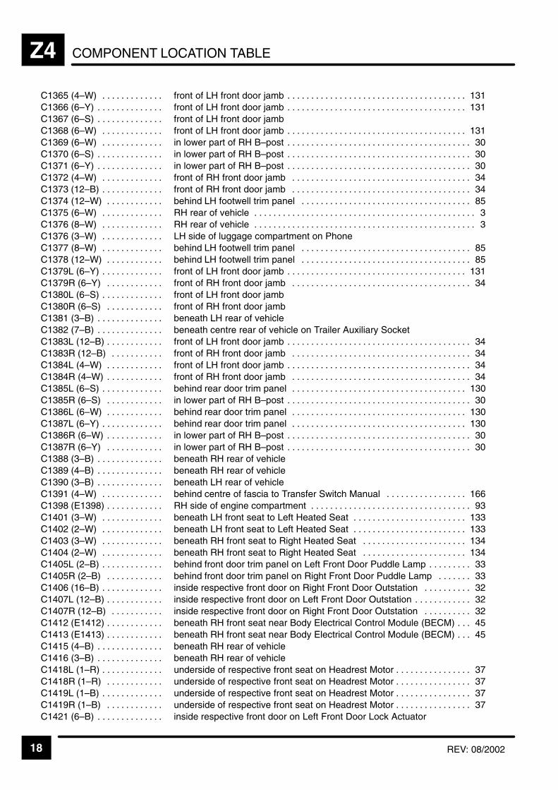
COMPONENT LOCATION TABLEZ4
18 REV: 08/2002
ÁÁÁÁÁÁÁÁÁÁÁÁÁÁÁÁÁÁÁÁ
C1365 (4–W) . . . . . . . . . . . . . ÁÁÁÁÁÁÁÁÁÁÁÁÁÁÁÁÁÁÁÁÁÁÁÁÁÁÁÁÁÁÁÁÁÁÁÁÁÁÁÁÁÁÁÁÁÁ
front of LH front door jamb 131. . . . . . . . . . . . . . . . . . . . . . . . . . . . . . . . . . . . . .
ÁÁÁÁÁÁÁÁÁÁC1366 (6–Y) . . . . . . . . . . . . . . ÁÁÁÁÁÁÁÁÁÁÁÁÁÁÁÁÁÁÁÁÁÁÁfront of LH front door jamb 131. . . . . . . . . . . . . . . . . . . . . . . . . . . . . . . . . . . . . . ÁÁÁÁÁÁÁÁÁÁÁÁÁÁÁÁÁÁÁÁ
C1367 (6–S) . . . . . . . . . . . . . . ÁÁÁÁÁÁÁÁÁÁÁÁÁÁÁÁÁÁÁÁÁÁÁÁÁÁÁÁÁÁÁÁÁÁÁÁÁÁÁÁÁÁÁÁÁÁ
front of LH front door jambÁÁÁÁÁÁÁÁÁÁÁÁÁÁÁÁÁÁÁÁ
C1368 (6–W) . . . . . . . . . . . . . ÁÁÁÁÁÁÁÁÁÁÁÁÁÁÁÁÁÁÁÁÁÁÁÁÁÁÁÁÁÁÁÁÁÁÁÁÁÁÁÁÁÁÁÁÁÁ
front of LH front door jamb 131. . . . . . . . . . . . . . . . . . . . . . . . . . . . . . . . . . . . . . ÁÁÁÁÁÁÁÁÁÁÁÁÁÁÁÁÁÁÁÁ
C1369 (6–W) . . . . . . . . . . . . . ÁÁÁÁÁÁÁÁÁÁÁÁÁÁÁÁÁÁÁÁÁÁÁÁÁÁÁÁÁÁÁÁÁÁÁÁÁÁÁÁÁÁÁÁÁÁ
in lower part of RH B–post 30. . . . . . . . . . . . . . . . . . . . . . . . . . . . . . . . . . . . . . . ÁÁÁÁÁÁÁÁÁÁÁÁÁÁÁÁÁÁÁÁ
C1370 (6–S) . . . . . . . . . . . . . . ÁÁÁÁÁÁÁÁÁÁÁÁÁÁÁÁÁÁÁÁÁÁÁÁÁÁÁÁÁÁÁÁÁÁÁÁÁÁÁÁÁÁÁÁÁÁ
in lower part of RH B–post 30. . . . . . . . . . . . . . . . . . . . . . . . . . . . . . . . . . . . . . .
ÁÁÁÁÁÁÁÁÁÁC1371 (6–Y) . . . . . . . . . . . . . . ÁÁÁÁÁÁÁÁÁÁÁÁÁÁÁÁÁÁÁÁÁÁÁin lower part of RH B–post 30. . . . . . . . . . . . . . . . . . . . . . . . . . . . . . . . . . . . . . . ÁÁÁÁÁÁÁÁÁÁÁÁÁÁÁÁÁÁÁÁC1372 (4–W) . . . . . . . . . . . . .
ÁÁÁÁÁÁÁÁÁÁÁÁÁÁÁÁÁÁÁÁÁÁÁÁÁÁÁÁÁÁÁÁÁÁÁÁÁÁÁÁÁÁÁÁÁÁfront of RH front door jamb 34. . . . . . . . . . . . . . . . . . . . . . . . . . . . . . . . . . . . . . ÁÁÁÁÁÁÁÁÁÁ
ÁÁÁÁÁÁÁÁÁÁC1373 (12–B) . . . . . . . . . . . . . ÁÁÁÁÁÁÁÁÁÁÁÁÁÁÁÁÁÁÁÁÁÁÁ
ÁÁÁÁÁÁÁÁÁÁÁÁÁÁÁÁÁÁÁÁÁÁÁfront of RH front door jamb 34. . . . . . . . . . . . . . . . . . . . . . . . . . . . . . . . . . . . . .
ÁÁÁÁÁÁÁÁÁÁÁÁÁÁÁÁÁÁÁÁ
C1374 (12–W) . . . . . . . . . . . . ÁÁÁÁÁÁÁÁÁÁÁÁÁÁÁÁÁÁÁÁÁÁÁÁÁÁÁÁÁÁÁÁÁÁÁÁÁÁÁÁÁÁÁÁÁÁ
behind LH footwell trim panel 85. . . . . . . . . . . . . . . . . . . . . . . . . . . . . . . . . . . . ÁÁÁÁÁÁÁÁÁÁÁÁÁÁÁÁÁÁÁÁ
C1375 (6–W) . . . . . . . . . . . . . ÁÁÁÁÁÁÁÁÁÁÁÁÁÁÁÁÁÁÁÁÁÁÁÁÁÁÁÁÁÁÁÁÁÁÁÁÁÁÁÁÁÁÁÁÁÁ
RH rear of vehicle 3. . . . . . . . . . . . . . . . . . . . . . . . . . . . . . . . . . . . . . . . . . . . . . .
ÁÁÁÁÁÁÁÁÁÁÁÁÁÁÁÁÁÁÁÁ
C1376 (8–W) . . . . . . . . . . . . . ÁÁÁÁÁÁÁÁÁÁÁÁÁÁÁÁÁÁÁÁÁÁÁÁÁÁÁÁÁÁÁÁÁÁÁÁÁÁÁÁÁÁÁÁÁÁ
RH rear of vehicle 3. . . . . . . . . . . . . . . . . . . . . . . . . . . . . . . . . . . . . . . . . . . . . . .
ÁÁÁÁÁÁÁÁÁÁC1376 (3–W) . . . . . . . . . . . . . ÁÁÁÁÁÁÁÁÁÁÁÁÁÁÁÁÁÁÁÁÁÁÁLH side of luggage compartment on PhoneÁÁÁÁÁÁÁÁÁÁÁÁÁÁÁÁÁÁÁÁ
C1377 (8–W) . . . . . . . . . . . . . ÁÁÁÁÁÁÁÁÁÁÁÁÁÁÁÁÁÁÁÁÁÁÁÁÁÁÁÁÁÁÁÁÁÁÁÁÁÁÁÁÁÁÁÁÁÁ
behind LH footwell trim panel 85. . . . . . . . . . . . . . . . . . . . . . . . . . . . . . . . . . . . ÁÁÁÁÁÁÁÁÁÁÁÁÁÁÁÁÁÁÁÁ
C1378 (12–W) . . . . . . . . . . . . ÁÁÁÁÁÁÁÁÁÁÁÁÁÁÁÁÁÁÁÁÁÁÁÁÁÁÁÁÁÁÁÁÁÁÁÁÁÁÁÁÁÁÁÁÁÁ
behind LH footwell trim panel 85. . . . . . . . . . . . . . . . . . . . . . . . . . . . . . . . . . . . ÁÁÁÁÁÁÁÁÁÁÁÁÁÁÁÁÁÁÁÁ
C1379L (6–Y) . . . . . . . . . . . . . ÁÁÁÁÁÁÁÁÁÁÁÁÁÁÁÁÁÁÁÁÁÁÁÁÁÁÁÁÁÁÁÁÁÁÁÁÁÁÁÁÁÁÁÁÁÁ
front of LH front door jamb 131. . . . . . . . . . . . . . . . . . . . . . . . . . . . . . . . . . . . . .
ÁÁÁÁÁÁÁÁÁÁÁÁÁÁÁÁÁÁÁÁ
C1379R (6–Y) . . . . . . . . . . . . ÁÁÁÁÁÁÁÁÁÁÁÁÁÁÁÁÁÁÁÁÁÁÁÁÁÁÁÁÁÁÁÁÁÁÁÁÁÁÁÁÁÁÁÁÁÁ
front of RH front door jamb 34. . . . . . . . . . . . . . . . . . . . . . . . . . . . . . . . . . . . . .
ÁÁÁÁÁÁÁÁÁÁC1380L (6–S) . . . . . . . . . . . . . ÁÁÁÁÁÁÁÁÁÁÁÁÁÁÁÁÁÁÁÁÁÁÁfront of LH front door jambÁÁÁÁÁÁÁÁÁÁÁÁÁÁÁÁÁÁÁÁ
C1380R (6–S) . . . . . . . . . . . . ÁÁÁÁÁÁÁÁÁÁÁÁÁÁÁÁÁÁÁÁÁÁÁÁÁÁÁÁÁÁÁÁÁÁÁÁÁÁÁÁÁÁÁÁÁÁ
front of RH front door jambÁÁÁÁÁÁÁÁÁÁÁÁÁÁÁÁÁÁÁÁ
C1381 (3–B) . . . . . . . . . . . . . . ÁÁÁÁÁÁÁÁÁÁÁÁÁÁÁÁÁÁÁÁÁÁÁÁÁÁÁÁÁÁÁÁÁÁÁÁÁÁÁÁÁÁÁÁÁÁ
beneath LH rear of vehicleÁÁÁÁÁÁÁÁÁÁÁÁÁÁÁÁÁÁÁÁ
C1382 (7–B) . . . . . . . . . . . . . . ÁÁÁÁÁÁÁÁÁÁÁÁÁÁÁÁÁÁÁÁÁÁÁÁÁÁÁÁÁÁÁÁÁÁÁÁÁÁÁÁÁÁÁÁÁÁ
beneath centre rear of vehicle on Trailer Auxiliary SocketÁÁÁÁÁÁÁÁÁÁÁÁÁÁÁÁÁÁÁÁ
C1383L (12–B) . . . . . . . . . . . . ÁÁÁÁÁÁÁÁÁÁÁÁÁÁÁÁÁÁÁÁÁÁÁÁÁÁÁÁÁÁÁÁÁÁÁÁÁÁÁÁÁÁÁÁÁÁ
front of LH front door jamb 34. . . . . . . . . . . . . . . . . . . . . . . . . . . . . . . . . . . . . . .
ÁÁÁÁÁÁÁÁÁÁC1383R (12–B) . . . . . . . . . . . ÁÁÁÁÁÁÁÁÁÁÁÁÁÁÁÁÁÁÁÁÁÁÁfront of RH front door jamb 34. . . . . . . . . . . . . . . . . . . . . . . . . . . . . . . . . . . . . . ÁÁÁÁÁÁÁÁÁÁÁÁÁÁÁÁÁÁÁÁC1384L (4–W) . . . . . . . . . . . .
ÁÁÁÁÁÁÁÁÁÁÁÁÁÁÁÁÁÁÁÁÁÁÁÁÁÁÁÁÁÁÁÁÁÁÁÁÁÁÁÁÁÁÁÁÁÁfront of LH front door jamb 34. . . . . . . . . . . . . . . . . . . . . . . . . . . . . . . . . . . . . . . ÁÁÁÁÁÁÁÁÁÁ
ÁÁÁÁÁÁÁÁÁÁC1384R (4–W) . . . . . . . . . . . . ÁÁÁÁÁÁÁÁÁÁÁÁÁÁÁÁÁÁÁÁÁÁÁ
ÁÁÁÁÁÁÁÁÁÁÁÁÁÁÁÁÁÁÁÁÁÁÁfront of RH front door jamb 34. . . . . . . . . . . . . . . . . . . . . . . . . . . . . . . . . . . . . .
ÁÁÁÁÁÁÁÁÁÁÁÁÁÁÁÁÁÁÁÁ
C1385L (6–S) . . . . . . . . . . . . . ÁÁÁÁÁÁÁÁÁÁÁÁÁÁÁÁÁÁÁÁÁÁÁÁÁÁÁÁÁÁÁÁÁÁÁÁÁÁÁÁÁÁÁÁÁÁ
behind rear door trim panel 130. . . . . . . . . . . . . . . . . . . . . . . . . . . . . . . . . . . . . ÁÁÁÁÁÁÁÁÁÁÁÁÁÁÁÁÁÁÁÁ
C1385R (6–S) . . . . . . . . . . . . ÁÁÁÁÁÁÁÁÁÁÁÁÁÁÁÁÁÁÁÁÁÁÁÁÁÁÁÁÁÁÁÁÁÁÁÁÁÁÁÁÁÁÁÁÁÁ
in lower part of RH B–post 30. . . . . . . . . . . . . . . . . . . . . . . . . . . . . . . . . . . . . . .
ÁÁÁÁÁÁÁÁÁÁÁÁÁÁÁÁÁÁÁÁ
C1386L (6–W) . . . . . . . . . . . . ÁÁÁÁÁÁÁÁÁÁÁÁÁÁÁÁÁÁÁÁÁÁÁÁÁÁÁÁÁÁÁÁÁÁÁÁÁÁÁÁÁÁÁÁÁÁ
behind rear door trim panel 130. . . . . . . . . . . . . . . . . . . . . . . . . . . . . . . . . . . . .
ÁÁÁÁÁÁÁÁÁÁC1387L (6–Y) . . . . . . . . . . . . . ÁÁÁÁÁÁÁÁÁÁÁÁÁÁÁÁÁÁÁÁÁÁÁbehind rear door trim panel 130. . . . . . . . . . . . . . . . . . . . . . . . . . . . . . . . . . . . . ÁÁÁÁÁÁÁÁÁÁÁÁÁÁÁÁÁÁÁÁ
C1386R (6–W) . . . . . . . . . . . . ÁÁÁÁÁÁÁÁÁÁÁÁÁÁÁÁÁÁÁÁÁÁÁÁÁÁÁÁÁÁÁÁÁÁÁÁÁÁÁÁÁÁÁÁÁÁ
in lower part of RH B–post 30. . . . . . . . . . . . . . . . . . . . . . . . . . . . . . . . . . . . . . . ÁÁÁÁÁÁÁÁÁÁÁÁÁÁÁÁÁÁÁÁ
C1387R (6–Y) . . . . . . . . . . . . ÁÁÁÁÁÁÁÁÁÁÁÁÁÁÁÁÁÁÁÁÁÁÁÁÁÁÁÁÁÁÁÁÁÁÁÁÁÁÁÁÁÁÁÁÁÁ
in lower part of RH B–post 30. . . . . . . . . . . . . . . . . . . . . . . . . . . . . . . . . . . . . . . ÁÁÁÁÁÁÁÁÁÁÁÁÁÁÁÁÁÁÁÁ
C1388 (3–B) . . . . . . . . . . . . . . ÁÁÁÁÁÁÁÁÁÁÁÁÁÁÁÁÁÁÁÁÁÁÁÁÁÁÁÁÁÁÁÁÁÁÁÁÁÁÁÁÁÁÁÁÁÁ
beneath RH rear of vehicle
ÁÁÁÁÁÁÁÁÁÁÁÁÁÁÁÁÁÁÁÁ
C1389 (4–B) . . . . . . . . . . . . . . ÁÁÁÁÁÁÁÁÁÁÁÁÁÁÁÁÁÁÁÁÁÁÁÁÁÁÁÁÁÁÁÁÁÁÁÁÁÁÁÁÁÁÁÁÁÁ
beneath RH rear of vehicle
ÁÁÁÁÁÁÁÁÁÁC1390 (3–B) . . . . . . . . . . . . . . ÁÁÁÁÁÁÁÁÁÁÁÁÁÁÁÁÁÁÁÁÁÁÁbeneath LH rear of vehicleÁÁÁÁÁÁÁÁÁÁÁÁÁÁÁÁÁÁÁÁ
C1391 (4–W) . . . . . . . . . . . . . ÁÁÁÁÁÁÁÁÁÁÁÁÁÁÁÁÁÁÁÁÁÁÁÁÁÁÁÁÁÁÁÁÁÁÁÁÁÁÁÁÁÁÁÁÁÁ
behind centre of fascia to Transfer Switch Manual 166. . . . . . . . . . . . . . . . . ÁÁÁÁÁÁÁÁÁÁÁÁÁÁÁÁÁÁÁÁ
C1398 (E1398) . . . . . . . . . . . . ÁÁÁÁÁÁÁÁÁÁÁÁÁÁÁÁÁÁÁÁÁÁÁÁÁÁÁÁÁÁÁÁÁÁÁÁÁÁÁÁÁÁÁÁÁÁ
RH side of engine compartment 93. . . . . . . . . . . . . . . . . . . . . . . . . . . . . . . . . . ÁÁÁÁÁÁÁÁÁÁÁÁÁÁÁÁÁÁÁÁ
C1401 (3–W) . . . . . . . . . . . . . ÁÁÁÁÁÁÁÁÁÁÁÁÁÁÁÁÁÁÁÁÁÁÁÁÁÁÁÁÁÁÁÁÁÁÁÁÁÁÁÁÁÁÁÁÁÁ
beneath LH front seat to Left Heated Seat 133. . . . . . . . . . . . . . . . . . . . . . . . ÁÁÁÁÁÁÁÁÁÁÁÁÁÁÁÁÁÁÁÁ
C1402 (2–W) . . . . . . . . . . . . . ÁÁÁÁÁÁÁÁÁÁÁÁÁÁÁÁÁÁÁÁÁÁÁÁÁÁÁÁÁÁÁÁÁÁÁÁÁÁÁÁÁÁÁÁÁÁ
beneath LH front seat to Left Heated Seat 133. . . . . . . . . . . . . . . . . . . . . . . .
ÁÁÁÁÁÁÁÁÁÁC1403 (3–W) . . . . . . . . . . . . . ÁÁÁÁÁÁÁÁÁÁÁÁÁÁÁÁÁÁÁÁÁÁÁbeneath RH front seat to Right Heated Seat 134. . . . . . . . . . . . . . . . . . . . . . ÁÁÁÁÁÁÁÁÁÁÁÁÁÁÁÁÁÁÁÁC1404 (2–W) . . . . . . . . . . . . .
ÁÁÁÁÁÁÁÁÁÁÁÁÁÁÁÁÁÁÁÁÁÁÁÁÁÁÁÁÁÁÁÁÁÁÁÁÁÁÁÁÁÁÁÁÁÁbeneath RH front seat to Right Heated Seat 134. . . . . . . . . . . . . . . . . . . . . . ÁÁÁÁÁÁÁÁÁÁ
ÁÁÁÁÁÁÁÁÁÁC1405L (2–B) . . . . . . . . . . . . . ÁÁÁÁÁÁÁÁÁÁÁÁÁÁÁÁÁÁÁÁÁÁÁ
ÁÁÁÁÁÁÁÁÁÁÁÁÁÁÁÁÁÁÁÁÁÁÁbehind front door trim panel on Left Front Door Puddle Lamp 33. . . . . . . . .
ÁÁÁÁÁÁÁÁÁÁÁÁÁÁÁÁÁÁÁÁ
C1405R (2–B) . . . . . . . . . . . . ÁÁÁÁÁÁÁÁÁÁÁÁÁÁÁÁÁÁÁÁÁÁÁÁÁÁÁÁÁÁÁÁÁÁÁÁÁÁÁÁÁÁÁÁÁÁ
behind front door trim panel on Right Front Door Puddle Lamp 33. . . . . . . ÁÁÁÁÁÁÁÁÁÁÁÁÁÁÁÁÁÁÁÁ
C1406 (16–B) . . . . . . . . . . . . . ÁÁÁÁÁÁÁÁÁÁÁÁÁÁÁÁÁÁÁÁÁÁÁÁÁÁÁÁÁÁÁÁÁÁÁÁÁÁÁÁÁÁÁÁÁÁ
inside respective front door on Right Front Door Outstation 32. . . . . . . . . .
ÁÁÁÁÁÁÁÁÁÁÁÁÁÁÁÁÁÁÁÁ
C1407L (12–B) . . . . . . . . . . . . ÁÁÁÁÁÁÁÁÁÁÁÁÁÁÁÁÁÁÁÁÁÁÁÁÁÁÁÁÁÁÁÁÁÁÁÁÁÁÁÁÁÁÁÁÁÁ
inside respective front door on Left Front Door Outstation 32. . . . . . . . . . . .
ÁÁÁÁÁÁÁÁÁÁC1407R (12–B) . . . . . . . . . . . ÁÁÁÁÁÁÁÁÁÁÁÁÁÁÁÁÁÁÁÁÁÁÁinside respective front door on Right Front Door Outstation 32. . . . . . . . . . ÁÁÁÁÁÁÁÁÁÁÁÁÁÁÁÁÁÁÁÁ
C1412 (E1412) . . . . . . . . . . . . ÁÁÁÁÁÁÁÁÁÁÁÁÁÁÁÁÁÁÁÁÁÁÁÁÁÁÁÁÁÁÁÁÁÁÁÁÁÁÁÁÁÁÁÁÁÁ
beneath RH front seat near Body Electrical Control Module (BECM) 45. . . ÁÁÁÁÁÁÁÁÁÁÁÁÁÁÁÁÁÁÁÁ
C1413 (E1413) . . . . . . . . . . . . ÁÁÁÁÁÁÁÁÁÁÁÁÁÁÁÁÁÁÁÁÁÁÁÁÁÁÁÁÁÁÁÁÁÁÁÁÁÁÁÁÁÁÁÁÁÁ
beneath RH front seat near Body Electrical Control Module (BECM) 45. . . ÁÁÁÁÁÁÁÁÁÁÁÁÁÁÁÁÁÁÁÁ
C1415 (4–B) . . . . . . . . . . . . . . ÁÁÁÁÁÁÁÁÁÁÁÁÁÁÁÁÁÁÁÁÁÁÁÁÁÁÁÁÁÁÁÁÁÁÁÁÁÁÁÁÁÁÁÁÁÁ
beneath RH rear of vehicle
ÁÁÁÁÁÁÁÁÁÁÁÁÁÁÁÁÁÁÁÁ
C1416 (3–B) . . . . . . . . . . . . . . ÁÁÁÁÁÁÁÁÁÁÁÁÁÁÁÁÁÁÁÁÁÁÁÁÁÁÁÁÁÁÁÁÁÁÁÁÁÁÁÁÁÁÁÁÁÁ
beneath RH rear of vehicle
ÁÁÁÁÁÁÁÁÁÁC1418L (1–R) . . . . . . . . . . . . . ÁÁÁÁÁÁÁÁÁÁÁÁÁÁÁÁÁÁÁÁÁÁÁunderside of respective front seat on Headrest Motor 37. . . . . . . . . . . . . . . . ÁÁÁÁÁÁÁÁÁÁÁÁÁÁÁÁÁÁÁÁ
C1418R (1–R) . . . . . . . . . . . . ÁÁÁÁÁÁÁÁÁÁÁÁÁÁÁÁÁÁÁÁÁÁÁÁÁÁÁÁÁÁÁÁÁÁÁÁÁÁÁÁÁÁÁÁÁÁ
underside of respective front seat on Headrest Motor 37. . . . . . . . . . . . . . . . ÁÁÁÁÁÁÁÁÁÁÁÁÁÁÁÁÁÁÁÁ
C1419L (1–B) . . . . . . . . . . . . . ÁÁÁÁÁÁÁÁÁÁÁÁÁÁÁÁÁÁÁÁÁÁÁÁÁÁÁÁÁÁÁÁÁÁÁÁÁÁÁÁÁÁÁÁÁÁ
underside of respective front seat on Headrest Motor 37. . . . . . . . . . . . . . . . ÁÁÁÁÁÁÁÁÁÁÁÁÁÁÁÁÁÁÁÁ
C1419R (1–B) . . . . . . . . . . . . ÁÁÁÁÁÁÁÁÁÁÁÁÁÁÁÁÁÁÁÁÁÁÁÁÁÁÁÁÁÁÁÁÁÁÁÁÁÁÁÁÁÁÁÁÁÁ
underside of respective front seat on Headrest Motor 37. . . . . . . . . . . . . . . . ÁÁÁÁÁÁÁÁÁÁÁÁÁÁÁÁÁÁÁÁ
C1421 (6–B) . . . . . . . . . . . . . . ÁÁÁÁÁÁÁÁÁÁÁÁÁÁÁÁÁÁÁÁÁÁÁÁÁÁÁÁÁÁÁÁÁÁÁÁÁÁÁÁÁÁÁÁÁÁ
inside respective front door on Left Front Door Lock Actuator
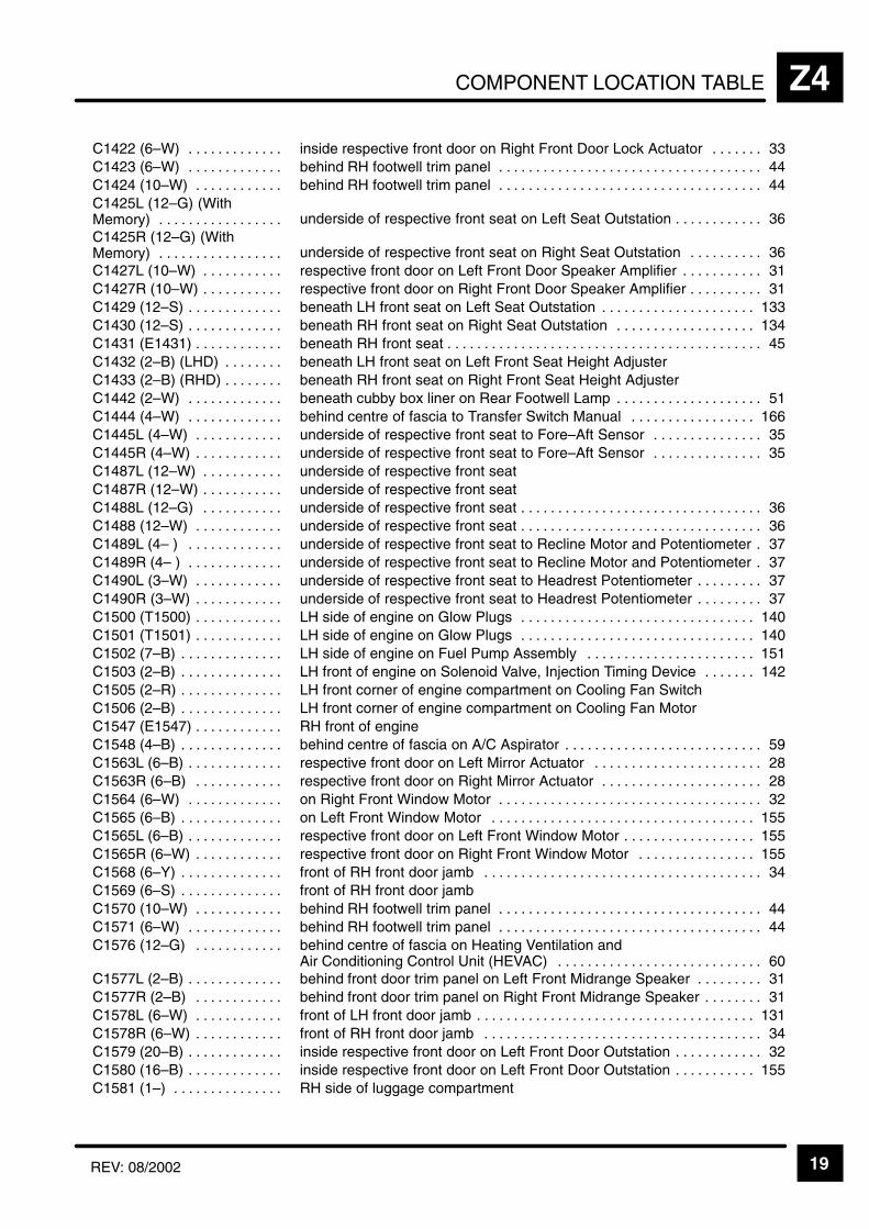
COMPONENT LOCATION TABLE Z4
19REV: 08/2002
ÁÁÁÁÁÁÁÁÁÁÁÁÁÁÁÁÁÁÁÁÁÁ
C1422 (6–W) . . . . . . . . . . . . . ÁÁÁÁÁÁÁÁÁÁÁÁÁÁÁÁÁÁÁÁÁÁÁÁÁÁÁÁÁÁÁÁÁÁÁÁÁÁÁÁÁÁÁÁÁÁinside respective front door on Right Front Door Lock Actuator 33. . . . . . .
ÁÁÁÁÁÁÁÁÁÁÁC1423 (6–W) . . . . . . . . . . . . . ÁÁÁÁÁÁÁÁÁÁÁÁÁÁÁÁÁÁÁÁÁÁÁbehind RH footwell trim panel 44. . . . . . . . . . . . . . . . . . . . . . . . . . . . . . . . . . . . ÁÁÁÁÁÁÁÁÁÁÁÁÁÁÁÁÁÁÁÁÁÁ
C1424 (10–W) . . . . . . . . . . . . ÁÁÁÁÁÁÁÁÁÁÁÁÁÁÁÁÁÁÁÁÁÁÁÁÁÁÁÁÁÁÁÁÁÁÁÁÁÁÁÁÁÁÁÁÁÁbehind RH footwell trim panel 44. . . . . . . . . . . . . . . . . . . . . . . . . . . . . . . . . . . .
ÁÁÁÁÁÁÁÁÁÁÁÁÁÁÁÁÁÁÁÁÁÁÁÁÁÁÁÁÁÁÁÁÁ
C1425L (12–G) (WithMemory) . . . . . . . . . . . . . . . . .
ÁÁÁÁÁÁÁÁÁÁÁÁÁÁÁÁÁÁÁÁÁÁÁÁÁÁÁÁÁÁÁÁÁÁÁÁÁÁÁÁÁÁÁÁÁÁÁÁÁÁÁÁÁÁÁÁÁÁÁÁÁÁÁÁÁÁÁÁÁunderside of respective front seat on Left Seat Outstation 36. . . . . . . . . . . .
ÁÁÁÁÁÁÁÁÁÁÁÁÁÁÁÁÁÁÁÁÁÁ
C1425R (12–G) (WithMemory) . . . . . . . . . . . . . . . . .
ÁÁÁÁÁÁÁÁÁÁÁÁÁÁÁÁÁÁÁÁÁÁÁÁÁÁÁÁÁÁÁÁÁÁÁÁÁÁÁÁÁÁÁÁÁÁunderside of respective front seat on Right Seat Outstation 36. . . . . . . . . .
ÁÁÁÁÁÁÁÁÁÁÁÁÁÁÁÁÁÁÁÁÁÁ
C1427L (10–W) . . . . . . . . . . . ÁÁÁÁÁÁÁÁÁÁÁÁÁÁÁÁÁÁÁÁÁÁÁÁÁÁÁÁÁÁÁÁÁÁÁÁÁÁÁÁÁÁÁÁÁÁrespective front door on Left Front Door Speaker Amplifier 31. . . . . . . . . . .
ÁÁÁÁÁÁÁÁÁÁÁÁÁÁÁÁÁÁÁÁÁÁ
C1427R (10–W) . . . . . . . . . . . ÁÁÁÁÁÁÁÁÁÁÁÁÁÁÁÁÁÁÁÁÁÁÁÁÁÁÁÁÁÁÁÁÁÁÁÁÁÁÁÁÁÁÁÁÁÁrespective front door on Right Front Door Speaker Amplifier 31. . . . . . . . . .
ÁÁÁÁÁÁÁÁÁÁÁÁÁÁÁÁÁÁÁÁÁÁ
C1429 (12–S) . . . . . . . . . . . . . ÁÁÁÁÁÁÁÁÁÁÁÁÁÁÁÁÁÁÁÁÁÁÁÁÁÁÁÁÁÁÁÁÁÁÁÁÁÁÁÁÁÁÁÁÁÁbeneath LH front seat on Left Seat Outstation 133. . . . . . . . . . . . . . . . . . . . .
ÁÁÁÁÁÁÁÁÁÁÁC1430 (12–S) . . . . . . . . . . . . . ÁÁÁÁÁÁÁÁÁÁÁÁÁÁÁÁÁÁÁÁÁÁÁbeneath RH front seat on Right Seat Outstation 134. . . . . . . . . . . . . . . . . . . ÁÁÁÁÁÁÁÁÁÁÁÁÁÁÁÁÁÁÁÁÁÁC1431 (E1431) . . . . . . . . . . . .
ÁÁÁÁÁÁÁÁÁÁÁÁÁÁÁÁÁÁÁÁÁÁÁÁÁÁÁÁÁÁÁÁÁÁÁÁÁÁÁÁÁÁÁÁÁÁbeneath RH front seat 45. . . . . . . . . . . . . . . . . . . . . . . . . . . . . . . . . . . . . . . . . . . ÁÁÁÁÁÁÁÁÁÁÁ
ÁÁÁÁÁÁÁÁÁÁÁC1432 (2–B) (LHD) . . . . . . . . ÁÁÁÁÁÁÁÁÁÁÁÁÁÁÁÁÁÁÁÁÁÁÁ
ÁÁÁÁÁÁÁÁÁÁÁÁÁÁÁÁÁÁÁÁÁÁÁbeneath LH front seat on Left Front Seat Height Adjuster
ÁÁÁÁÁÁÁÁÁÁÁÁÁÁÁÁÁÁÁÁÁÁ
C1433 (2–B) (RHD) . . . . . . . . ÁÁÁÁÁÁÁÁÁÁÁÁÁÁÁÁÁÁÁÁÁÁÁÁÁÁÁÁÁÁÁÁÁÁÁÁÁÁÁÁÁÁÁÁÁÁbeneath RH front seat on Right Front Seat Height Adjuster
ÁÁÁÁÁÁÁÁÁÁÁÁÁÁÁÁÁÁÁÁÁÁ
C1442 (2–W) . . . . . . . . . . . . . ÁÁÁÁÁÁÁÁÁÁÁÁÁÁÁÁÁÁÁÁÁÁÁÁÁÁÁÁÁÁÁÁÁÁÁÁÁÁÁÁÁÁÁÁÁÁbeneath cubby box liner on Rear Footwell Lamp 51. . . . . . . . . . . . . . . . . . . .
ÁÁÁÁÁÁÁÁÁÁÁÁÁÁÁÁÁÁÁÁÁÁ
C1444 (4–W) . . . . . . . . . . . . . ÁÁÁÁÁÁÁÁÁÁÁÁÁÁÁÁÁÁÁÁÁÁÁÁÁÁÁÁÁÁÁÁÁÁÁÁÁÁÁÁÁÁÁÁÁÁbehind centre of fascia to Transfer Switch Manual 166. . . . . . . . . . . . . . . . .
ÁÁÁÁÁÁÁÁÁÁÁC1445L (4–W) . . . . . . . . . . . . ÁÁÁÁÁÁÁÁÁÁÁÁÁÁÁÁÁÁÁÁÁÁÁunderside of respective front seat to Fore–Aft Sensor 35. . . . . . . . . . . . . . . ÁÁÁÁÁÁÁÁÁÁÁÁÁÁÁÁÁÁÁÁÁÁ
C1445R (4–W) . . . . . . . . . . . . ÁÁÁÁÁÁÁÁÁÁÁÁÁÁÁÁÁÁÁÁÁÁÁÁÁÁÁÁÁÁÁÁÁÁÁÁÁÁÁÁÁÁÁÁÁÁunderside of respective front seat to Fore–Aft Sensor 35. . . . . . . . . . . . . . .
ÁÁÁÁÁÁÁÁÁÁÁÁÁÁÁÁÁÁÁÁÁÁ
C1487L (12–W) . . . . . . . . . . . ÁÁÁÁÁÁÁÁÁÁÁÁÁÁÁÁÁÁÁÁÁÁÁÁÁÁÁÁÁÁÁÁÁÁÁÁÁÁÁÁÁÁÁÁÁÁunderside of respective front seat
ÁÁÁÁÁÁÁÁÁÁÁÁÁÁÁÁÁÁÁÁÁÁ
C1487R (12–W) . . . . . . . . . . . ÁÁÁÁÁÁÁÁÁÁÁÁÁÁÁÁÁÁÁÁÁÁÁÁÁÁÁÁÁÁÁÁÁÁÁÁÁÁÁÁÁÁÁÁÁÁunderside of respective front seat
ÁÁÁÁÁÁÁÁÁÁÁÁÁÁÁÁÁÁÁÁÁÁ
C1488L (12–G) . . . . . . . . . . . ÁÁÁÁÁÁÁÁÁÁÁÁÁÁÁÁÁÁÁÁÁÁÁÁÁÁÁÁÁÁÁÁÁÁÁÁÁÁÁÁÁÁÁÁÁÁunderside of respective front seat 36. . . . . . . . . . . . . . . . . . . . . . . . . . . . . . . . .
ÁÁÁÁÁÁÁÁÁÁÁC1488 (12–W) . . . . . . . . . . . . ÁÁÁÁÁÁÁÁÁÁÁÁÁÁÁÁÁÁÁÁÁÁÁunderside of respective front seat 36. . . . . . . . . . . . . . . . . . . . . . . . . . . . . . . . . ÁÁÁÁÁÁÁÁÁÁÁÁÁÁÁÁÁÁÁÁÁÁ
C1489L (4– ) . . . . . . . . . . . . . ÁÁÁÁÁÁÁÁÁÁÁÁÁÁÁÁÁÁÁÁÁÁÁÁÁÁÁÁÁÁÁÁÁÁÁÁÁÁÁÁÁÁÁÁÁÁunderside of respective front seat to Recline Motor and Potentiometer 37.
ÁÁÁÁÁÁÁÁÁÁÁÁÁÁÁÁÁÁÁÁÁÁ
C1489R (4– ) . . . . . . . . . . . . . ÁÁÁÁÁÁÁÁÁÁÁÁÁÁÁÁÁÁÁÁÁÁÁÁÁÁÁÁÁÁÁÁÁÁÁÁÁÁÁÁÁÁÁÁÁÁunderside of respective front seat to Recline Motor and Potentiometer 37.
ÁÁÁÁÁÁÁÁÁÁÁÁÁÁÁÁÁÁÁÁÁÁ
C1490L (3–W) . . . . . . . . . . . . ÁÁÁÁÁÁÁÁÁÁÁÁÁÁÁÁÁÁÁÁÁÁÁÁÁÁÁÁÁÁÁÁÁÁÁÁÁÁÁÁÁÁÁÁÁÁunderside of respective front seat to Headrest Potentiometer 37. . . . . . . . .
ÁÁÁÁÁÁÁÁÁÁÁÁÁÁÁÁÁÁÁÁÁÁ
C1490R (3–W) . . . . . . . . . . . . ÁÁÁÁÁÁÁÁÁÁÁÁÁÁÁÁÁÁÁÁÁÁÁÁÁÁÁÁÁÁÁÁÁÁÁÁÁÁÁÁÁÁÁÁÁÁunderside of respective front seat to Headrest Potentiometer 37. . . . . . . . .
ÁÁÁÁÁÁÁÁÁÁÁC1500 (T1500) . . . . . . . . . . . . ÁÁÁÁÁÁÁÁÁÁÁÁÁÁÁÁÁÁÁÁÁÁÁLH side of engine on Glow Plugs 140. . . . . . . . . . . . . . . . . . . . . . . . . . . . . . . . ÁÁÁÁÁÁÁÁÁÁÁÁÁÁÁÁÁÁÁÁÁÁC1501 (T1501) . . . . . . . . . . . .
ÁÁÁÁÁÁÁÁÁÁÁÁÁÁÁÁÁÁÁÁÁÁÁÁÁÁÁÁÁÁÁÁÁÁÁÁÁÁÁÁÁÁÁÁÁÁLH side of engine on Glow Plugs 140. . . . . . . . . . . . . . . . . . . . . . . . . . . . . . . . ÁÁÁÁÁÁÁÁÁÁÁ
ÁÁÁÁÁÁÁÁÁÁÁC1502 (7–B) . . . . . . . . . . . . . . ÁÁÁÁÁÁÁÁÁÁÁÁÁÁÁÁÁÁÁÁÁÁÁ
ÁÁÁÁÁÁÁÁÁÁÁÁÁÁÁÁÁÁÁÁÁÁÁLH side of engine on Fuel Pump Assembly 151. . . . . . . . . . . . . . . . . . . . . . .
ÁÁÁÁÁÁÁÁÁÁÁÁÁÁÁÁÁÁÁÁÁÁ
C1503 (2–B) . . . . . . . . . . . . . . ÁÁÁÁÁÁÁÁÁÁÁÁÁÁÁÁÁÁÁÁÁÁÁÁÁÁÁÁÁÁÁÁÁÁÁÁÁÁÁÁÁÁÁÁÁÁLH front of engine on Solenoid Valve, Injection Timing Device 142. . . . . . .
ÁÁÁÁÁÁÁÁÁÁÁÁÁÁÁÁÁÁÁÁÁÁ
C1505 (2–R) . . . . . . . . . . . . . . ÁÁÁÁÁÁÁÁÁÁÁÁÁÁÁÁÁÁÁÁÁÁÁÁÁÁÁÁÁÁÁÁÁÁÁÁÁÁÁÁÁÁÁÁÁÁLH front corner of engine compartment on Cooling Fan Switch
ÁÁÁÁÁÁÁÁÁÁÁÁÁÁÁÁÁÁÁÁÁÁ
C1506 (2–B) . . . . . . . . . . . . . . ÁÁÁÁÁÁÁÁÁÁÁÁÁÁÁÁÁÁÁÁÁÁÁÁÁÁÁÁÁÁÁÁÁÁÁÁÁÁÁÁÁÁÁÁÁÁLH front corner of engine compartment on Cooling Fan Motor
ÁÁÁÁÁÁÁÁÁÁÁC1547 (E1547) . . . . . . . . . . . . ÁÁÁÁÁÁÁÁÁÁÁÁÁÁÁÁÁÁÁÁÁÁÁRH front of engineÁÁÁÁÁÁÁÁÁÁÁÁÁÁÁÁÁÁÁÁÁÁ
C1548 (4–B) . . . . . . . . . . . . . . ÁÁÁÁÁÁÁÁÁÁÁÁÁÁÁÁÁÁÁÁÁÁÁÁÁÁÁÁÁÁÁÁÁÁÁÁÁÁÁÁÁÁÁÁÁÁbehind centre of fascia on A/C Aspirator 59. . . . . . . . . . . . . . . . . . . . . . . . . . .
ÁÁÁÁÁÁÁÁÁÁÁÁÁÁÁÁÁÁÁÁÁÁ
C1563L (6–B) . . . . . . . . . . . . . ÁÁÁÁÁÁÁÁÁÁÁÁÁÁÁÁÁÁÁÁÁÁÁÁÁÁÁÁÁÁÁÁÁÁÁÁÁÁÁÁÁÁÁÁÁÁrespective front door on Left Mirror Actuator 28. . . . . . . . . . . . . . . . . . . . . . .
ÁÁÁÁÁÁÁÁÁÁÁÁÁÁÁÁÁÁÁÁÁÁ
C1563R (6–B) . . . . . . . . . . . . ÁÁÁÁÁÁÁÁÁÁÁÁÁÁÁÁÁÁÁÁÁÁÁÁÁÁÁÁÁÁÁÁÁÁÁÁÁÁÁÁÁÁÁÁÁÁrespective front door on Right Mirror Actuator 28. . . . . . . . . . . . . . . . . . . . . .
ÁÁÁÁÁÁÁÁÁÁÁÁÁÁÁÁÁÁÁÁÁÁ
C1564 (6–W) . . . . . . . . . . . . . ÁÁÁÁÁÁÁÁÁÁÁÁÁÁÁÁÁÁÁÁÁÁÁÁÁÁÁÁÁÁÁÁÁÁÁÁÁÁÁÁÁÁÁÁÁÁon Right Front Window Motor 32. . . . . . . . . . . . . . . . . . . . . . . . . . . . . . . . . . . .
ÁÁÁÁÁÁÁÁÁÁÁC1565 (6–B) . . . . . . . . . . . . . . ÁÁÁÁÁÁÁÁÁÁÁÁÁÁÁÁÁÁÁÁÁÁÁon Left Front Window Motor 155. . . . . . . . . . . . . . . . . . . . . . . . . . . . . . . . . . . . ÁÁÁÁÁÁÁÁÁÁÁÁÁÁÁÁÁÁÁÁÁÁ
C1565L (6–B) . . . . . . . . . . . . . ÁÁÁÁÁÁÁÁÁÁÁÁÁÁÁÁÁÁÁÁÁÁÁÁÁÁÁÁÁÁÁÁÁÁÁÁÁÁÁÁÁÁÁÁÁÁrespective front door on Left Front Window Motor 155. . . . . . . . . . . . . . . . . .
ÁÁÁÁÁÁÁÁÁÁÁÁÁÁÁÁÁÁÁÁÁÁ
C1565R (6–W) . . . . . . . . . . . . ÁÁÁÁÁÁÁÁÁÁÁÁÁÁÁÁÁÁÁÁÁÁÁÁÁÁÁÁÁÁÁÁÁÁÁÁÁÁÁÁÁÁÁÁÁÁrespective front door on Right Front Window Motor 155. . . . . . . . . . . . . . . .
ÁÁÁÁÁÁÁÁÁÁÁÁÁÁÁÁÁÁÁÁÁÁ
C1568 (6–Y) . . . . . . . . . . . . . . ÁÁÁÁÁÁÁÁÁÁÁÁÁÁÁÁÁÁÁÁÁÁÁÁÁÁÁÁÁÁÁÁÁÁÁÁÁÁÁÁÁÁÁÁÁÁfront of RH front door jamb 34. . . . . . . . . . . . . . . . . . . . . . . . . . . . . . . . . . . . . .
ÁÁÁÁÁÁÁÁÁÁÁÁÁÁÁÁÁÁÁÁÁÁ
C1569 (6–S) . . . . . . . . . . . . . . ÁÁÁÁÁÁÁÁÁÁÁÁÁÁÁÁÁÁÁÁÁÁÁÁÁÁÁÁÁÁÁÁÁÁÁÁÁÁÁÁÁÁÁÁÁÁfront of RH front door jamb
ÁÁÁÁÁÁÁÁÁÁÁC1570 (10–W) . . . . . . . . . . . . ÁÁÁÁÁÁÁÁÁÁÁÁÁÁÁÁÁÁÁÁÁÁÁbehind RH footwell trim panel 44. . . . . . . . . . . . . . . . . . . . . . . . . . . . . . . . . . . . ÁÁÁÁÁÁÁÁÁÁÁÁÁÁÁÁÁÁÁÁÁÁC1571 (6–W) . . . . . . . . . . . . .
ÁÁÁÁÁÁÁÁÁÁÁÁÁÁÁÁÁÁÁÁÁÁÁÁÁÁÁÁÁÁÁÁÁÁÁÁÁÁÁÁÁÁÁÁÁÁbehind RH footwell trim panel 44. . . . . . . . . . . . . . . . . . . . . . . . . . . . . . . . . . . . ÁÁÁÁÁÁÁÁÁÁÁ
ÁÁÁÁÁÁÁÁÁÁÁÁÁÁÁÁÁÁÁÁÁÁ
C1576 (12–G) . . . . . . . . . . . . ÁÁÁÁÁÁÁÁÁÁÁÁÁÁÁÁÁÁÁÁÁÁÁÁÁÁÁÁÁÁÁÁÁÁÁÁÁÁÁÁÁÁÁÁÁÁÁÁÁÁÁÁÁÁÁÁÁÁÁÁÁÁÁÁÁÁÁÁÁ
behind centre of fascia on Heating Ventilation and Air Conditioning Control Unit (HEVAC) 60. . . . . . . . . . . . . . . . . . . . . . . . . . . .
ÁÁÁÁÁÁÁÁÁÁÁÁÁÁÁÁÁÁÁÁÁÁ
C1577L (2–B) . . . . . . . . . . . . . ÁÁÁÁÁÁÁÁÁÁÁÁÁÁÁÁÁÁÁÁÁÁÁÁÁÁÁÁÁÁÁÁÁÁÁÁÁÁÁÁÁÁÁÁÁÁbehind front door trim panel on Left Front Midrange Speaker 31. . . . . . . . .
ÁÁÁÁÁÁÁÁÁÁÁC1577R (2–B) . . . . . . . . . . . . ÁÁÁÁÁÁÁÁÁÁÁÁÁÁÁÁÁÁÁÁÁÁÁbehind front door trim panel on Right Front Midrange Speaker 31. . . . . . . . ÁÁÁÁÁÁÁÁÁÁÁÁÁÁÁÁÁÁÁÁÁÁ
C1578L (6–W) . . . . . . . . . . . . ÁÁÁÁÁÁÁÁÁÁÁÁÁÁÁÁÁÁÁÁÁÁÁÁÁÁÁÁÁÁÁÁÁÁÁÁÁÁÁÁÁÁÁÁÁÁfront of LH front door jamb 131. . . . . . . . . . . . . . . . . . . . . . . . . . . . . . . . . . . . . .
ÁÁÁÁÁÁÁÁÁÁÁÁÁÁÁÁÁÁÁÁÁÁ
C1578R (6–W) . . . . . . . . . . . . ÁÁÁÁÁÁÁÁÁÁÁÁÁÁÁÁÁÁÁÁÁÁÁÁÁÁÁÁÁÁÁÁÁÁÁÁÁÁÁÁÁÁÁÁÁÁfront of RH front door jamb 34. . . . . . . . . . . . . . . . . . . . . . . . . . . . . . . . . . . . . .
ÁÁÁÁÁÁÁÁÁÁÁÁÁÁÁÁÁÁÁÁÁÁ
C1579 (20–B) . . . . . . . . . . . . . ÁÁÁÁÁÁÁÁÁÁÁÁÁÁÁÁÁÁÁÁÁÁÁÁÁÁÁÁÁÁÁÁÁÁÁÁÁÁÁÁÁÁÁÁÁÁinside respective front door on Left Front Door Outstation 32. . . . . . . . . . . .
ÁÁÁÁÁÁÁÁÁÁÁÁÁÁÁÁÁÁÁÁÁÁ
C1580 (16–B) . . . . . . . . . . . . . ÁÁÁÁÁÁÁÁÁÁÁÁÁÁÁÁÁÁÁÁÁÁÁÁÁÁÁÁÁÁÁÁÁÁÁÁÁÁÁÁÁÁÁÁÁÁinside respective front door on Left Front Door Outstation 155. . . . . . . . . . .
ÁÁÁÁÁÁÁÁÁÁÁC1581 (1–) . . . . . . . . . . . . . . . ÁÁÁÁÁÁÁÁÁÁÁÁÁÁÁÁÁÁÁÁÁÁÁRH side of luggage compartment

COMPONENT LOCATION TABLEZ4
20 REV: 08/2002
ÁÁÁÁÁÁÁÁÁÁÁÁÁÁÁÁÁÁÁÁ
C1582 (1–) . . . . . . . . . . . . . . . ÁÁÁÁÁÁÁÁÁÁÁÁÁÁÁÁÁÁÁÁÁÁÁÁÁÁÁÁÁÁÁÁÁÁÁÁÁÁÁÁÁÁÁÁÁÁ
lower RH side of windscreen 175. . . . . . . . . . . . . . . . . . . . . . . . . . . . . . . . . . . .
ÁÁÁÁÁÁÁÁÁÁC1583 (6–W) . . . . . . . . . . . . . ÁÁÁÁÁÁÁÁÁÁÁÁÁÁÁÁÁÁÁÁÁÁÁfront of RH front door jamb 34. . . . . . . . . . . . . . . . . . . . . . . . . . . . . . . . . . . . . . ÁÁÁÁÁÁÁÁÁÁÁÁÁÁÁÁÁÁÁÁ
C1584 (18–B) . . . . . . . . . . . . ÁÁÁÁÁÁÁÁÁÁÁÁÁÁÁÁÁÁÁÁÁÁÁÁÁÁÁÁÁÁÁÁÁÁÁÁÁÁÁÁÁÁÁÁÁÁ
behind glovebox on Anti–Lock Brake System ECU 52. . . . . . . . . . . . . . . . . . ÁÁÁÁÁÁÁÁÁÁÁÁÁÁÁÁÁÁÁÁ
C1584 (18–S) . . . . . . . . . . . . . ÁÁÁÁÁÁÁÁÁÁÁÁÁÁÁÁÁÁÁÁÁÁÁÁÁÁÁÁÁÁÁÁÁÁÁÁÁÁÁÁÁÁÁÁÁÁ
beneath RH front seat on Body Electrical Control Module (BECM) 38. . . . ÁÁÁÁÁÁÁÁÁÁÁÁÁÁÁÁÁÁÁÁ
C1585 (15–B) . . . . . . . . . . . . . ÁÁÁÁÁÁÁÁÁÁÁÁÁÁÁÁÁÁÁÁÁÁÁÁÁÁÁÁÁÁÁÁÁÁÁÁÁÁÁÁÁÁÁÁÁÁ
behind glovebox on Anti–Lock Brake System ECU 52. . . . . . . . . . . . . . . . . . ÁÁÁÁÁÁÁÁÁÁÁÁÁÁÁÁÁÁÁÁ
C1585 (20–U) . . . . . . . . . . . . . ÁÁÁÁÁÁÁÁÁÁÁÁÁÁÁÁÁÁÁÁÁÁÁÁÁÁÁÁÁÁÁÁÁÁÁÁÁÁÁÁÁÁÁÁÁÁ
beneath RH front seat on Body Electrical Control Module (BECM) 39. . . .
ÁÁÁÁÁÁÁÁÁÁC1586 (9–B) . . . . . . . . . . . . . . ÁÁÁÁÁÁÁÁÁÁÁÁÁÁÁÁÁÁÁÁÁÁÁbehind glovebox on Anti–Lock Brake System ECU 52. . . . . . . . . . . . . . . . . . ÁÁÁÁÁÁÁÁÁÁÁÁÁÁÁÁÁÁÁÁC1586 (12–S) . . . . . . . . . . . . .
ÁÁÁÁÁÁÁÁÁÁÁÁÁÁÁÁÁÁÁÁÁÁÁÁÁÁÁÁÁÁÁÁÁÁÁÁÁÁÁÁÁÁÁÁÁÁbeneath RH front seat on Body Electrical Control Module (BECM) 38. . . . ÁÁÁÁÁÁÁÁÁÁ
ÁÁÁÁÁÁÁÁÁÁC1587 (4–S) . . . . . . . . . . . . . . ÁÁÁÁÁÁÁÁÁÁÁÁÁÁÁÁÁÁÁÁÁÁÁ
ÁÁÁÁÁÁÁÁÁÁÁÁÁÁÁÁÁÁÁÁÁÁÁbeneath RH front seat on Body Electrical Control Module (BECM) 38. . . .
ÁÁÁÁÁÁÁÁÁÁÁÁÁÁÁÁÁÁÁÁ
C1587R (6–Y) . . . . . . . . . . . . ÁÁÁÁÁÁÁÁÁÁÁÁÁÁÁÁÁÁÁÁÁÁÁÁÁÁÁÁÁÁÁÁÁÁÁÁÁÁÁÁÁÁÁÁÁÁ
behind rear door trim panel 30. . . . . . . . . . . . . . . . . . . . . . . . . . . . . . . . . . . . . . ÁÁÁÁÁÁÁÁÁÁÁÁÁÁÁÁÁÁÁÁ
C1588 (2–B) . . . . . . . . . . . . . . ÁÁÁÁÁÁÁÁÁÁÁÁÁÁÁÁÁÁÁÁÁÁÁÁÁÁÁÁÁÁÁÁÁÁÁÁÁÁÁÁÁÁÁÁÁÁ
driver’s side of engine compartment on Brake Fluid Level Switch 88. . . . .
ÁÁÁÁÁÁÁÁÁÁÁÁÁÁÁÁÁÁÁÁ
C1588 (1–) . . . . . . . . . . . . . . . ÁÁÁÁÁÁÁÁÁÁÁÁÁÁÁÁÁÁÁÁÁÁÁÁÁÁÁÁÁÁÁÁÁÁÁÁÁÁÁÁÁÁÁÁÁÁ
centre rear of roof
ÁÁÁÁÁÁÁÁÁÁC1590 (5–B) . . . . . . . . . . . . . . ÁÁÁÁÁÁÁÁÁÁÁÁÁÁÁÁÁÁÁÁÁÁÁLH side of engine compartment on ABS Pressure Switch Unit 77. . . . . . . . ÁÁÁÁÁÁÁÁÁÁÁÁÁÁÁÁÁÁÁÁ
C1591 (13–B) . . . . . . . . . . . . . ÁÁÁÁÁÁÁÁÁÁÁÁÁÁÁÁÁÁÁÁÁÁÁÁÁÁÁÁÁÁÁÁÁÁÁÁÁÁÁÁÁÁÁÁÁÁ
driver’s side of engine compartment on ABS Booster Unit 128. . . . . . . . . . . ÁÁÁÁÁÁÁÁÁÁÁÁÁÁÁÁÁÁÁÁ
C1592 (1–W) . . . . . . . . . . . . . ÁÁÁÁÁÁÁÁÁÁÁÁÁÁÁÁÁÁÁÁÁÁÁÁÁÁÁÁÁÁÁÁÁÁÁÁÁÁÁÁÁÁÁÁÁÁ
driver’s side of engine compartment on ABS Booster Unit 128. . . . . . . . . . . ÁÁÁÁÁÁÁÁÁÁÁÁÁÁÁÁÁÁÁÁ
C1593 (4–B) (LHD) . . . . . . . . ÁÁÁÁÁÁÁÁÁÁÁÁÁÁÁÁÁÁÁÁÁÁÁÁÁÁÁÁÁÁÁÁÁÁÁÁÁÁÁÁÁÁÁÁÁÁ
lower LH side of windscreen to Front Wiper Motor 154. . . . . . . . . . . . . . . . .
ÁÁÁÁÁÁÁÁÁÁÁÁÁÁÁÁÁÁÁÁ
C1594 (2–B) . . . . . . . . . . . . . . ÁÁÁÁÁÁÁÁÁÁÁÁÁÁÁÁÁÁÁÁÁÁÁÁÁÁÁÁÁÁÁÁÁÁÁÁÁÁÁÁÁÁÁÁÁÁ
beneath centre console on Fascia Cigar Lighter 54. . . . . . . . . . . . . . . . . . . .
ÁÁÁÁÁÁÁÁÁÁC1595 (1–W) . . . . . . . . . . . . . ÁÁÁÁÁÁÁÁÁÁÁÁÁÁÁÁÁÁÁÁÁÁÁbeneath centre console on Fascia Cigar Lighter 54. . . . . . . . . . . . . . . . . . . . ÁÁÁÁÁÁÁÁÁÁÁÁÁÁÁÁÁÁÁÁ
C1597 . . . . . . . . . . . . . . . . . . . ÁÁÁÁÁÁÁÁÁÁÁÁÁÁÁÁÁÁÁÁÁÁÁÁÁÁÁÁÁÁÁÁÁÁÁÁÁÁÁÁÁÁÁÁÁÁ
behind centre of fascia 60. . . . . . . . . . . . . . . . . . . . . . . . . . . . . . . . . . . . . . . . . . ÁÁÁÁÁÁÁÁÁÁÁÁÁÁÁÁÁÁÁÁÁÁÁÁÁÁÁÁÁÁ
C1597 . . . . . . . . . . . . . . . . . . . ÁÁÁÁÁÁÁÁÁÁÁÁÁÁÁÁÁÁÁÁÁÁÁÁÁÁÁÁÁÁÁÁÁÁÁÁÁÁÁÁÁÁÁÁÁÁÁÁÁÁÁÁÁÁÁÁÁÁÁÁÁÁÁÁÁÁÁÁÁ
behind centre of fascia on Heating Ventilation and Air Conditioning Control Unit (HEVAC) 60. . . . . . . . . . . . . . . . . . . . . . . . . . . .
ÁÁÁÁÁÁÁÁÁÁÁÁÁÁÁÁÁÁÁÁ
C1618L . . . . . . . . . . . . . . . . . . ÁÁÁÁÁÁÁÁÁÁÁÁÁÁÁÁÁÁÁÁÁÁÁÁÁÁÁÁÁÁÁÁÁÁÁÁÁÁÁÁÁÁÁÁÁÁ
underside of respective front seat on Left Seat Outstation 165. . . . . . . . . . .
ÁÁÁÁÁÁÁÁÁÁC1618R . . . . . . . . . . . . . . . . . . ÁÁÁÁÁÁÁÁÁÁÁÁÁÁÁÁÁÁÁÁÁÁÁunderside of respective front seat on Right Seat Outstation 165. . . . . . . . . ÁÁÁÁÁÁÁÁÁÁÁÁÁÁÁÁÁÁÁÁ
C1619 (With Memory) . . . . . . ÁÁÁÁÁÁÁÁÁÁÁÁÁÁÁÁÁÁÁÁÁÁÁÁÁÁÁÁÁÁÁÁÁÁÁÁÁÁÁÁÁÁÁÁÁÁ
underside of respective front seat on Left Seat Outstation 165. . . . . . . . . . . ÁÁÁÁÁÁÁÁÁÁÁÁÁÁÁÁÁÁÁÁ
C1619 (Without Memory) . . . ÁÁÁÁÁÁÁÁÁÁÁÁÁÁÁÁÁÁÁÁÁÁÁÁÁÁÁÁÁÁÁÁÁÁÁÁÁÁÁÁÁÁÁÁÁÁ
underside of respective front seat to Left Seat Switch 165. . . . . . . . . . . . . . ÁÁÁÁÁÁÁÁÁÁÁÁÁÁÁÁÁÁÁÁ
C1620 (With Memory) . . . . . . ÁÁÁÁÁÁÁÁÁÁÁÁÁÁÁÁÁÁÁÁÁÁÁÁÁÁÁÁÁÁÁÁÁÁÁÁÁÁÁÁÁÁÁÁÁÁ
underside of respective front seat on Right Seat Outstation 167. . . . . . . . .
ÁÁÁÁÁÁÁÁÁÁÁÁÁÁÁÁÁÁÁÁ
C1620 (18–W) (WithoutMemory) . . . . . . . . . . . . . . . . .
ÁÁÁÁÁÁÁÁÁÁÁÁÁÁÁÁÁÁÁÁÁÁÁÁÁÁÁÁÁÁÁÁÁÁÁÁÁÁÁÁÁÁÁÁÁÁunderside of respective front seat to Right Seat Switch 167. . . . . . . . . . . . . ÁÁÁÁÁÁÁÁÁÁ
ÁÁÁÁÁÁÁÁÁÁC1621 (10–W) . . . . . . . . . . . . ÁÁÁÁÁÁÁÁÁÁÁÁÁÁÁÁÁÁÁÁÁÁÁ
ÁÁÁÁÁÁÁÁÁÁÁÁÁÁÁÁÁÁÁÁÁÁÁLH side of luggage compartment on Subwoofer Amplifier 13. . . . . . . . . . . .
ÁÁÁÁÁÁÁÁÁÁÁÁÁÁÁÁÁÁÁÁ
C1622 (6–W) . . . . . . . . . . . . . ÁÁÁÁÁÁÁÁÁÁÁÁÁÁÁÁÁÁÁÁÁÁÁÁÁÁÁÁÁÁÁÁÁÁÁÁÁÁÁÁÁÁÁÁÁÁ
LH side of luggage compartment to Subwoofer 13. . . . . . . . . . . . . . . . . . . . .
ÁÁÁÁÁÁÁÁÁÁÁÁÁÁÁÁÁÁÁÁ
E0119 . . . . . . . . . . . . . . . . . . . ÁÁÁÁÁÁÁÁÁÁÁÁÁÁÁÁÁÁÁÁÁÁÁÁÁÁÁÁÁÁÁÁÁÁÁÁÁÁÁÁÁÁÁÁÁÁÁÁ
centre rear of engine compartmentÁÁÁÁÁÁÁÁÁÁÁÁÁÁÁÁÁÁÁÁ
E0360 . . . . . . . . . . . . . . . . . . . ÁÁÁÁÁÁÁÁÁÁÁÁÁÁÁÁÁÁÁÁÁÁÁÁÁÁÁÁÁÁÁÁÁÁÁÁÁÁÁÁÁÁÁÁÁÁÁÁ
beneath centre console 47. . . . . . . . . . . . . . . . . . . . . . . . . . . . . . . . . . . . . . . . .
ÁÁÁÁÁÁÁÁÁÁE0361 . . . . . . . . . . . . . . . . . . . ÁÁÁÁÁÁÁÁÁÁÁÁÁÁÁÁÁÁÁÁÁÁÁÁbehind centre of fascia 60. . . . . . . . . . . . . . . . . . . . . . . . . . . . . . . . . . . . . . . . . . ÁÁÁÁÁÁÁÁÁÁÁÁÁÁÁÁÁÁÁÁE0500 . . . . . . . . . . . . . . . . . . .
ÁÁÁÁÁÁÁÁÁÁÁÁÁÁÁÁÁÁÁÁÁÁÁÁÁÁÁÁÁÁÁÁÁÁÁÁÁÁÁÁÁÁÁÁÁÁÁÁRH rear of engine compartment near Engine Compartment Fuse Box 74. ÁÁÁÁÁÁÁÁÁÁ
ÁÁÁÁÁÁÁÁÁÁE0556 . . . . . . . . . . . . . . . . . . .
ÁÁÁÁÁÁÁÁÁÁÁÁÁÁÁÁÁÁÁÁÁÁÁÁÁÁÁÁÁÁÁÁÁÁÁÁÁÁÁÁÁÁÁÁÁÁÁÁ
LH rear of engine compartment near Air Valve Block 110. . . . . . . . . . . . . . . ÁÁÁÁÁÁÁÁÁÁÁÁÁÁÁÁÁÁÁÁ
E0556D . . . . . . . . . . . . . . . . . . ÁÁÁÁÁÁÁÁÁÁÁÁÁÁÁÁÁÁÁÁÁÁÁÁÁÁÁÁÁÁÁÁÁÁÁÁÁÁÁÁÁÁÁÁÁÁÁÁ
beneath Engine Compartment Fuse Box 136. . . . . . . . . . . . . . . . . . . . . . . . . . ÁÁÁÁÁÁÁÁÁÁÁÁÁÁÁÁÁÁÁÁ
E0557 . . . . . . . . . . . . . . . . . . . ÁÁÁÁÁÁÁÁÁÁÁÁÁÁÁÁÁÁÁÁÁÁÁÁÁÁÁÁÁÁÁÁÁÁÁÁÁÁÁÁÁÁÁÁÁÁÁÁ
LH front of engine compartment 110. . . . . . . . . . . . . . . . . . . . . . . . . . . . . . . . . ÁÁÁÁÁÁÁÁÁÁÁÁÁÁÁÁÁÁÁÁ
E0558 . . . . . . . . . . . . . . . . . . . ÁÁÁÁÁÁÁÁÁÁÁÁÁÁÁÁÁÁÁÁÁÁÁÁÁÁÁÁÁÁÁÁÁÁÁÁÁÁÁÁÁÁÁÁÁÁÁÁ
LH rear of engine compartment near Air Valve Block 110. . . . . . . . . . . . . . .
ÁÁÁÁÁÁÁÁÁÁÁÁÁÁÁÁÁÁÁÁ
E0559 . . . . . . . . . . . . . . . . . . . ÁÁÁÁÁÁÁÁÁÁÁÁÁÁÁÁÁÁÁÁÁÁÁÁÁÁÁÁÁÁÁÁÁÁÁÁÁÁÁÁÁÁÁÁÁÁÁÁ
RH rear of engine compartment near Engine Compartment Fuse Box 74.
ÁÁÁÁÁÁÁÁÁÁE0560 . . . . . . . . . . . . . . . . . . . ÁÁÁÁÁÁÁÁÁÁÁÁÁÁÁÁÁÁÁÁÁÁÁÁRH side of engine compartment 93. . . . . . . . . . . . . . . . . . . . . . . . . . . . . . . . . . ÁÁÁÁÁÁÁÁÁÁÁÁÁÁÁÁÁÁÁÁE0561 . . . . . . . . . . . . . . . . . . .
ÁÁÁÁÁÁÁÁÁÁÁÁÁÁÁÁÁÁÁÁÁÁÁÁÁÁÁÁÁÁÁÁÁÁÁÁÁÁÁÁÁÁÁÁÁÁÁÁRH side of engine compartment 93. . . . . . . . . . . . . . . . . . . . . . . . . . . . . . . . . . ÁÁÁÁÁÁÁÁÁÁ
ÁÁÁÁÁÁÁÁÁÁE0562 . . . . . . . . . . . . . . . . . . .
ÁÁÁÁÁÁÁÁÁÁÁÁÁÁÁÁÁÁÁÁÁÁÁÁÁÁÁÁÁÁÁÁÁÁÁÁÁÁÁÁÁÁÁÁÁÁÁÁ
behind RH footwell trim panel 89. . . . . . . . . . . . . . . . . . . . . . . . . . . . . . . . . . . . ÁÁÁÁÁÁÁÁÁÁÁÁÁÁÁÁÁÁÁÁ
E0563 . . . . . . . . . . . . . . . . . . . ÁÁÁÁÁÁÁÁÁÁÁÁÁÁÁÁÁÁÁÁÁÁÁÁÁÁÁÁÁÁÁÁÁÁÁÁÁÁÁÁÁÁÁÁÁÁÁÁ
RH rear of engine compartmentÁÁÁÁÁÁÁÁÁÁÁÁÁÁÁÁÁÁÁÁ
E0564 . . . . . . . . . . . . . . . . . . . ÁÁÁÁÁÁÁÁÁÁÁÁÁÁÁÁÁÁÁÁÁÁÁÁÁÁÁÁÁÁÁÁÁÁÁÁÁÁÁÁÁÁÁÁÁÁÁÁ
behind RH footwell trim panel 89. . . . . . . . . . . . . . . . . . . . . . . . . . . . . . . . . . . . ÁÁÁÁÁÁÁÁÁÁÁÁÁÁÁÁÁÁÁÁ
E0565 . . . . . . . . . . . . . . . . . . . ÁÁÁÁÁÁÁÁÁÁÁÁÁÁÁÁÁÁÁÁÁÁÁÁÁÁÁÁÁÁÁÁÁÁÁÁÁÁÁÁÁÁÁÁÁÁÁÁ
RH side of luggage compartment 6. . . . . . . . . . . . . . . . . . . . . . . . . . . . . . . . . .
ÁÁÁÁÁÁÁÁÁÁÁÁÁÁÁÁÁÁÁÁ
E0807 . . . . . . . . . . . . . . . . . . . ÁÁÁÁÁÁÁÁÁÁÁÁÁÁÁÁÁÁÁÁÁÁÁÁÁÁÁÁÁÁÁÁÁÁÁÁÁÁÁÁÁÁÁÁÁÁÁÁ
RH side of luggage compartment 6. . . . . . . . . . . . . . . . . . . . . . . . . . . . . . . . . .
ÁÁÁÁÁÁÁÁÁÁE0808 . . . . . . . . . . . . . . . . . . . ÁÁÁÁÁÁÁÁÁÁÁÁÁÁÁÁÁÁÁÁÁÁÁÁbeneath RH front seat on Body Electrical Control Module (BECM) 45. . . . ÁÁÁÁÁÁÁÁÁÁÁÁÁÁÁÁÁÁÁÁ
E0809 . . . . . . . . . . . . . . . . . . . ÁÁÁÁÁÁÁÁÁÁÁÁÁÁÁÁÁÁÁÁÁÁÁÁÁÁÁÁÁÁÁÁÁÁÁÁÁÁÁÁÁÁÁÁÁÁÁÁ
LH side of luggage compartment 19. . . . . . . . . . . . . . . . . . . . . . . . . . . . . . . . . ÁÁÁÁÁÁÁÁÁÁÁÁÁÁÁÁÁÁÁÁ
E0810 . . . . . . . . . . . . . . . . . . . ÁÁÁÁÁÁÁÁÁÁÁÁÁÁÁÁÁÁÁÁÁÁÁÁÁÁÁÁÁÁÁÁÁÁÁÁÁÁÁÁÁÁÁÁÁÁÁÁ
centre rear of engine compartment 76. . . . . . . . . . . . . . . . . . . . . . . . . . . . . . . ÁÁÁÁÁÁÁÁÁÁÁÁÁÁÁÁÁÁÁÁ
E0811 . . . . . . . . . . . . . . . . . . . ÁÁÁÁÁÁÁÁÁÁÁÁÁÁÁÁÁÁÁÁÁÁÁÁÁÁÁÁÁÁÁÁÁÁÁÁÁÁÁÁÁÁÁÁÁÁÁÁ
centre rear of engine compartment 76. . . . . . . . . . . . . . . . . . . . . . . . . . . . . . .
ÁÁÁÁÁÁÁÁÁÁÁÁÁÁÁÁÁÁÁÁ
E0822 . . . . . . . . . . . . . . . . . . . ÁÁÁÁÁÁÁÁÁÁÁÁÁÁÁÁÁÁÁÁÁÁÁÁÁÁÁÁÁÁÁÁÁÁÁÁÁÁÁÁÁÁÁÁÁÁÁÁ
on Chassis
ÁÁÁÁÁÁÁÁÁÁE0910 . . . . . . . . . . . . . . . . . . . ÁÁÁÁÁÁÁÁÁÁÁÁÁÁÁÁÁÁÁÁÁÁÁÁbehind RH footwell trim panel 89. . . . . . . . . . . . . . . . . . . . . . . . . . . . . . . . . . . .
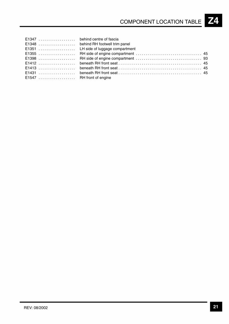
COMPONENT LOCATION TABLE Z4
21REV: 08/2002
ÁÁÁÁÁÁÁÁÁÁÁÁÁÁÁÁÁÁÁÁE1347 . . . . . . . . . . . . . . . . . . . ÁÁÁÁÁÁÁÁÁÁÁÁÁÁÁÁÁÁÁÁÁÁÁ
ÁÁÁÁÁÁÁÁÁÁÁÁÁÁÁÁÁÁÁÁÁÁÁbehind centre of fascia
ÁÁÁÁÁÁÁÁÁÁE1348 . . . . . . . . . . . . . . . . . . . ÁÁÁÁÁÁÁÁÁÁÁÁÁÁÁÁÁÁÁÁÁÁÁbehind RH footwell trim panelÁÁÁÁÁÁÁÁÁÁÁÁÁÁÁÁÁÁÁÁE1351 . . . . . . . . . . . . . . . . . . .
ÁÁÁÁÁÁÁÁÁÁÁÁÁÁÁÁÁÁÁÁÁÁÁÁÁÁÁÁÁÁÁÁÁÁÁÁÁÁÁÁÁÁÁÁÁÁ
LH side of luggage compartmentÁÁÁÁÁÁÁÁÁÁÁÁÁÁÁÁÁÁÁÁE1355 . . . . . . . . . . . . . . . . . . . ÁÁÁÁÁÁÁÁÁÁÁÁÁÁÁÁÁÁÁÁÁÁÁ
ÁÁÁÁÁÁÁÁÁÁÁÁÁÁÁÁÁÁÁÁÁÁÁRH side of engine compartment 45. . . . . . . . . . . . . . . . . . . . . . . . . . . . . . . . . .
ÁÁÁÁÁÁÁÁÁÁÁÁÁÁÁÁÁÁÁÁE1398 . . . . . . . . . . . . . . . . . . . ÁÁÁÁÁÁÁÁÁÁÁÁÁÁÁÁÁÁÁÁÁÁÁ
ÁÁÁÁÁÁÁÁÁÁÁÁÁÁÁÁÁÁÁÁÁÁÁRH side of engine compartment 93. . . . . . . . . . . . . . . . . . . . . . . . . . . . . . . . . .
ÁÁÁÁÁÁÁÁÁÁÁÁÁÁÁÁÁÁÁÁE1412 . . . . . . . . . . . . . . . . . . . ÁÁÁÁÁÁÁÁÁÁÁÁÁÁÁÁÁÁÁÁÁÁÁ
ÁÁÁÁÁÁÁÁÁÁÁÁÁÁÁÁÁÁÁÁÁÁÁbeneath RH front seat 45. . . . . . . . . . . . . . . . . . . . . . . . . . . . . . . . . . . . . . . . . . .
ÁÁÁÁÁÁÁÁÁÁE1413 . . . . . . . . . . . . . . . . . . . ÁÁÁÁÁÁÁÁÁÁÁÁÁÁÁÁÁÁÁÁÁÁÁbeneath RH front seat 45. . . . . . . . . . . . . . . . . . . . . . . . . . . . . . . . . . . . . . . . . . . ÁÁÁÁÁÁÁÁÁÁÁÁÁÁÁÁÁÁÁÁE1431 . . . . . . . . . . . . . . . . . . .
ÁÁÁÁÁÁÁÁÁÁÁÁÁÁÁÁÁÁÁÁÁÁÁÁÁÁÁÁÁÁÁÁÁÁÁÁÁÁÁÁÁÁÁÁÁÁbeneath RH front seat 45. . . . . . . . . . . . . . . . . . . . . . . . . . . . . . . . . . . . . . . . . . . ÁÁÁÁÁÁÁÁÁÁ
ÁÁÁÁÁÁÁÁÁÁE1547 . . . . . . . . . . . . . . . . . . . ÁÁÁÁÁÁÁÁÁÁÁÁÁÁÁÁÁÁÁÁÁÁÁ
ÁÁÁÁÁÁÁÁÁÁÁÁÁÁÁÁÁÁÁÁÁÁÁRH front of engine

KEY INFORMATIONi
"
"
(
(
(
&0'!
'-&
08'0;'
=+ # 9 0
000
>+ # 9 #
*= # 9 0
00 000
& # 9 0
07 00
>* 8
0&-0 08&
5 6
5 6
;# "
0 #
7 #
&9
(
08';0
0 # 9
1 & ;
1 & %
#
1 #
1 ? # 7
0 56
#
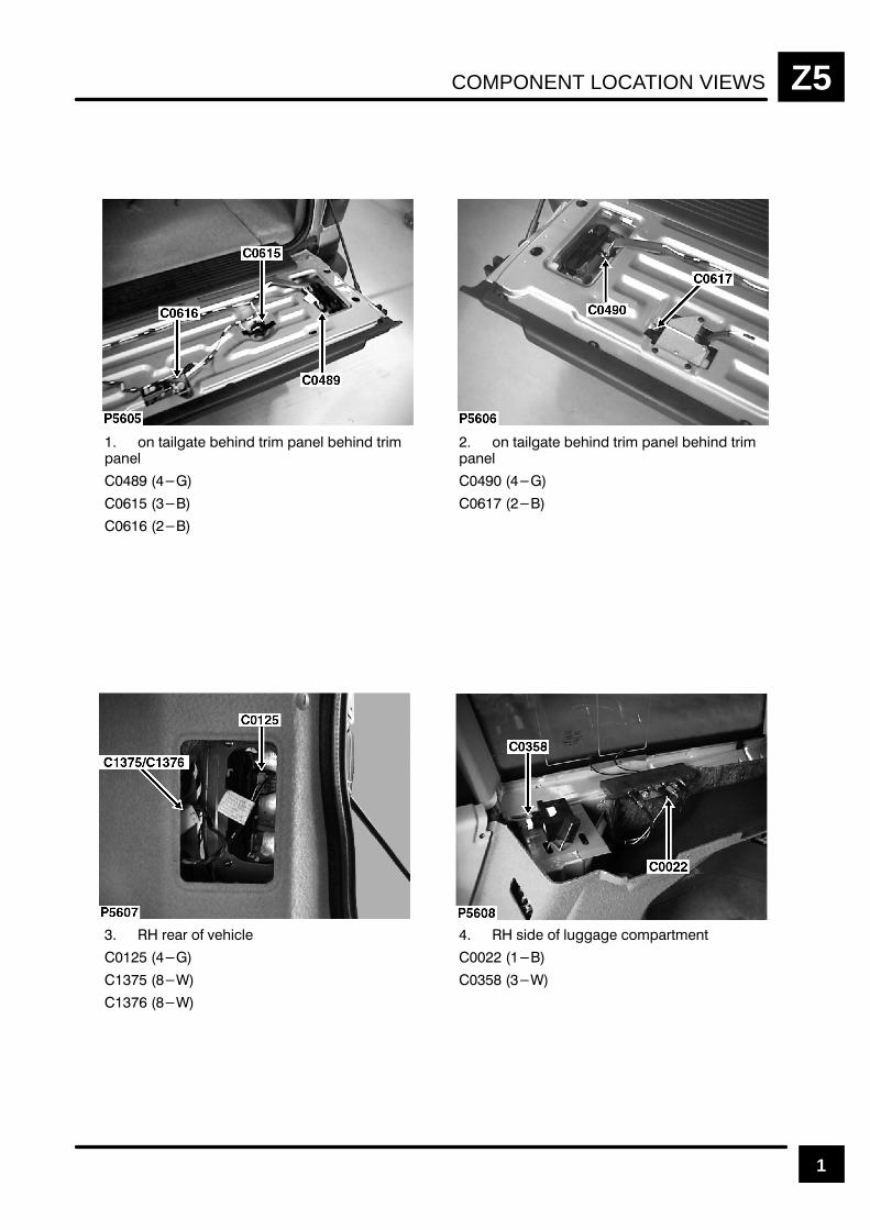
COMPONENT LOCATION VIEWS Z5
1
"! && ! &$ #! ! &$ #!
"! && ! &$ #! ! &$ #!
$$ " (
% " ' " #$& !&

COMPONENT LOCATION VIEWSZ5
2
## ! & !"#% %
$ ! & !"#% %
%# ! %%
%# ! %% %# "
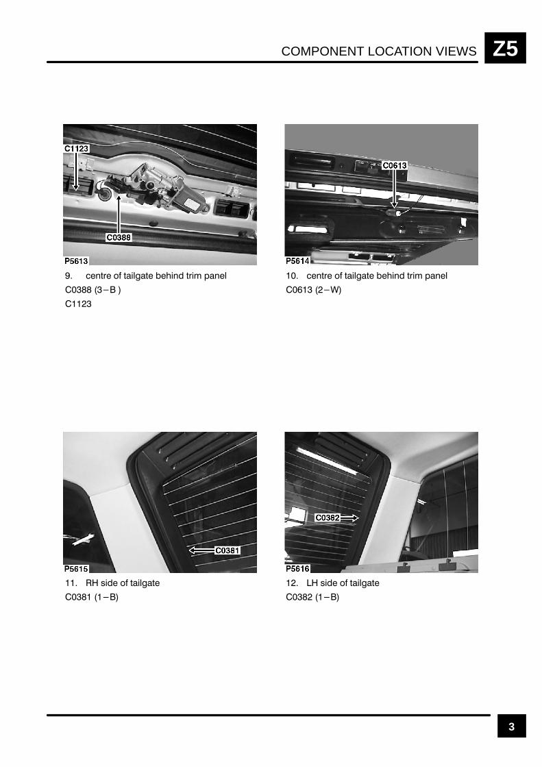
COMPONENT LOCATION VIEWS Z5
3
#! ## #!
#! ## #!
" ##
" ##

COMPONENT LOCATION VIEWSZ5
4
% " ' " #$& !&
!% $"!& " $$ ""$ &$ $ "(
!&$ " !!
!&$ " !!
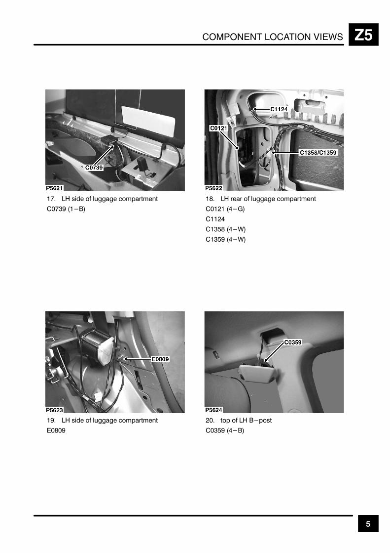
COMPONENT LOCATION VIEWS Z5
5
!
" #
" #
$
"
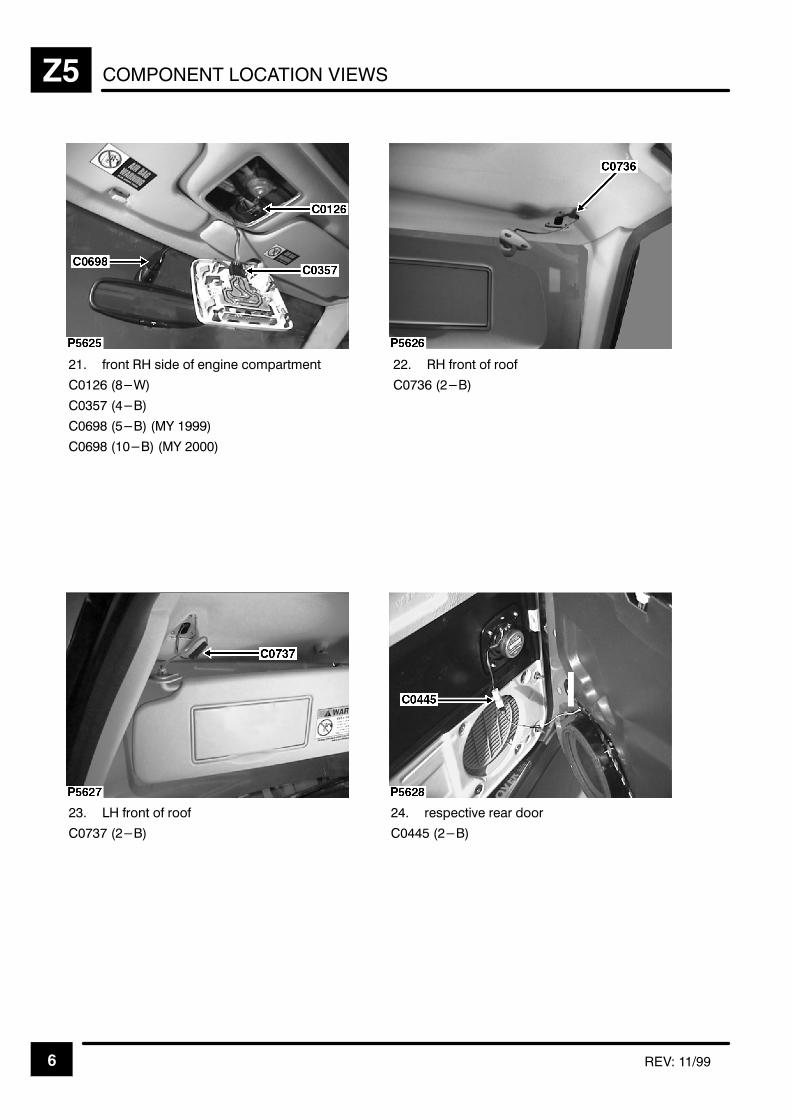
COMPONENT LOCATION VIEWSZ5
6 REV: 11/99
%
& #
"
& " '(
& '(
%
&
)
"
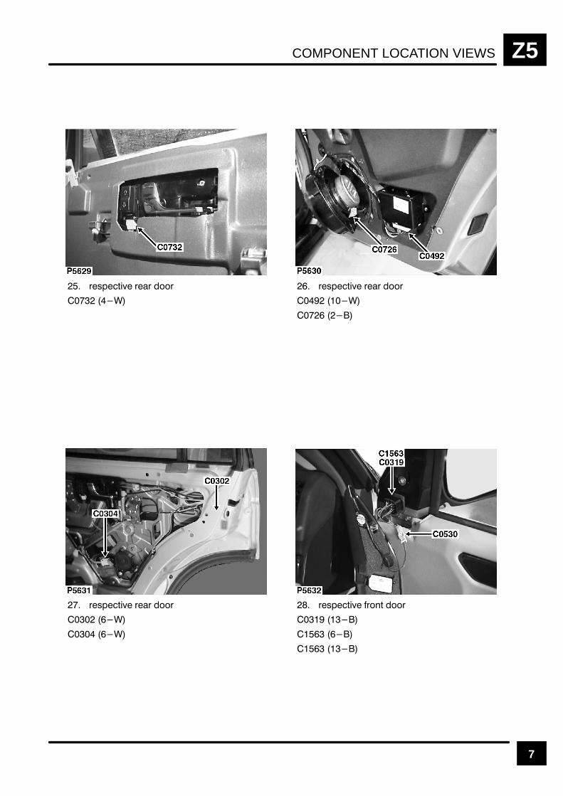
COMPONENT LOCATION VIEWS Z5
7
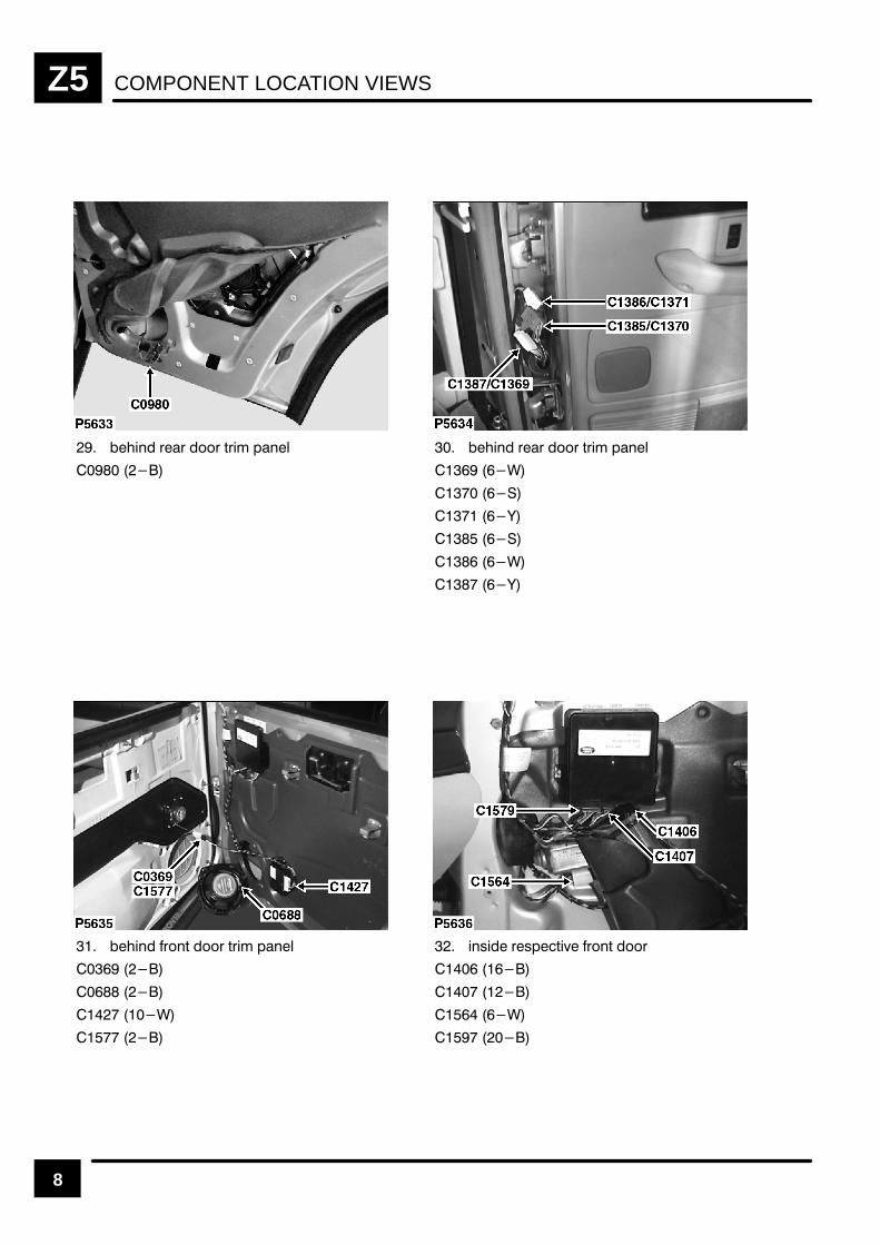
COMPONENT LOCATION VIEWSZ5
8
"" " $" !
"" " $" !
" $ " $" !
# "#!$% " $ "
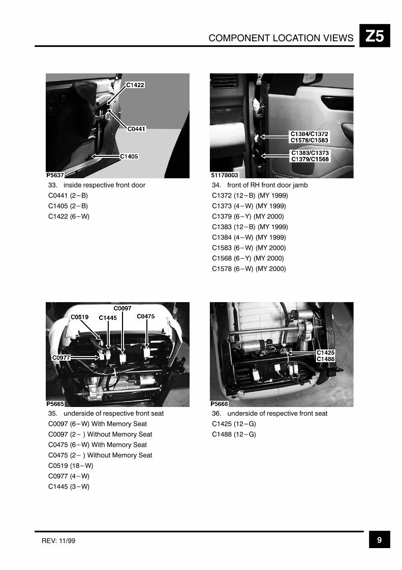
COMPONENT LOCATION VIEWS Z5
9REV: 11/99
)
"
&#
% *+
'(
# '(
&( '(
'(
# '(
" &# '(
"& &( '(
" &# '(
" )
&# #, '- .
#, '- .
" &# #, '- .
" #, '- .
" #
#
" #
& )
" !
!
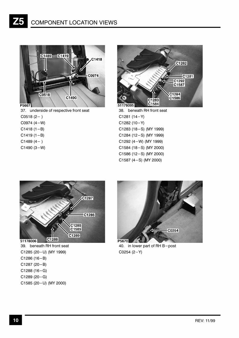
COMPONENT LOCATION VIEWSZ5
10 REV: 11/99
)
"
#
#
+, %
(
(
. '(
. '(
# '(
" . '(
"& . '(
" . '(
+, %
" / '(
& &
&!
!
"" / '(
0 %
" (
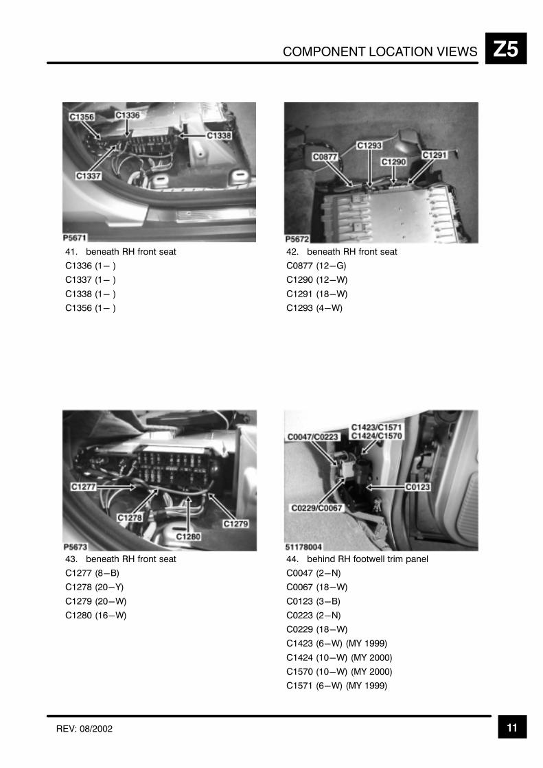
COMPONENT LOCATION VIEWS Z5
11REV: 08/2002
!
"
# "$
"%#"&
"% &
"%&
" '
" "#(
"%"#&
" #&
)* +,
##"-
## &
#"'
#"""-
#""% &
"&.(%%%
"#&.("###
!##&.("###
!&.(%%%
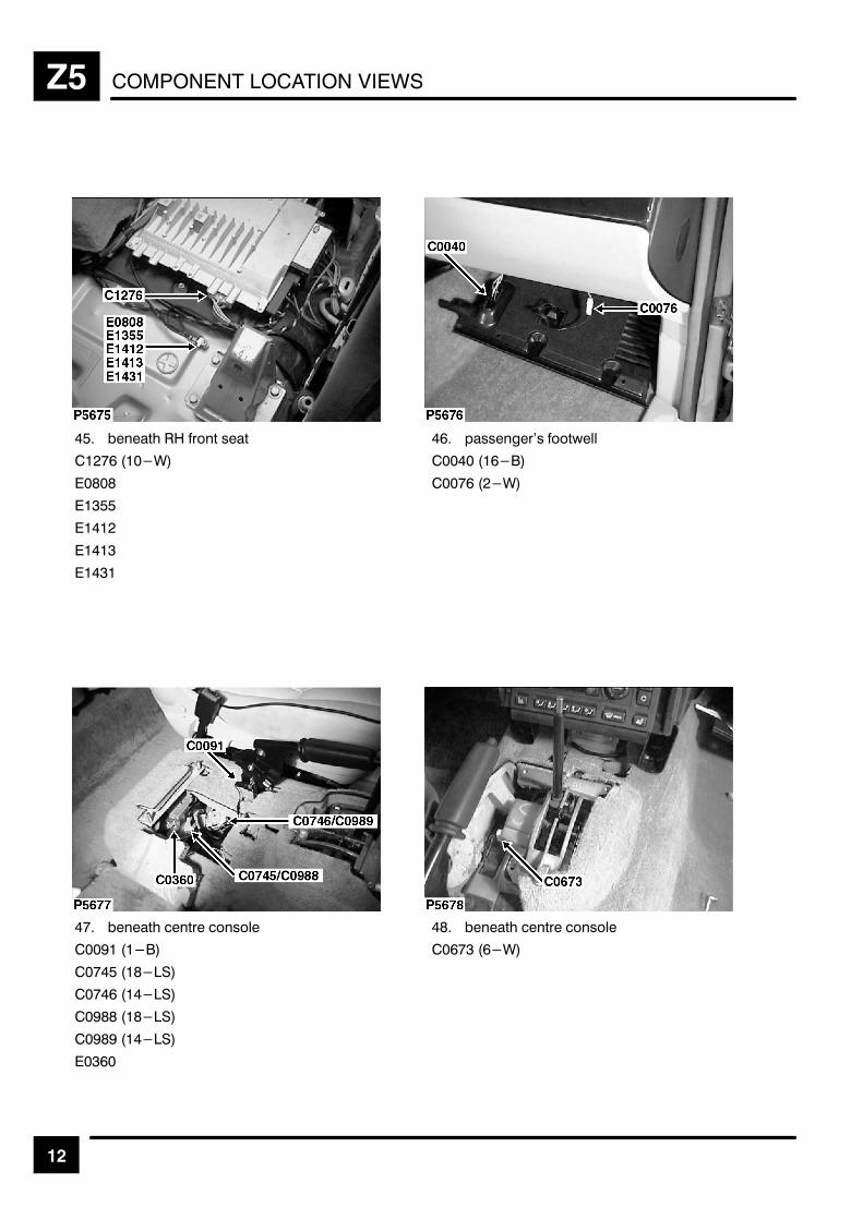
COMPONENT LOCATION VIEWSZ5
12
" +, %
& #
$
$""
$
$
$
& 2 0
&
& #
+,
" .
& .
.
.
$&
+,
& &#
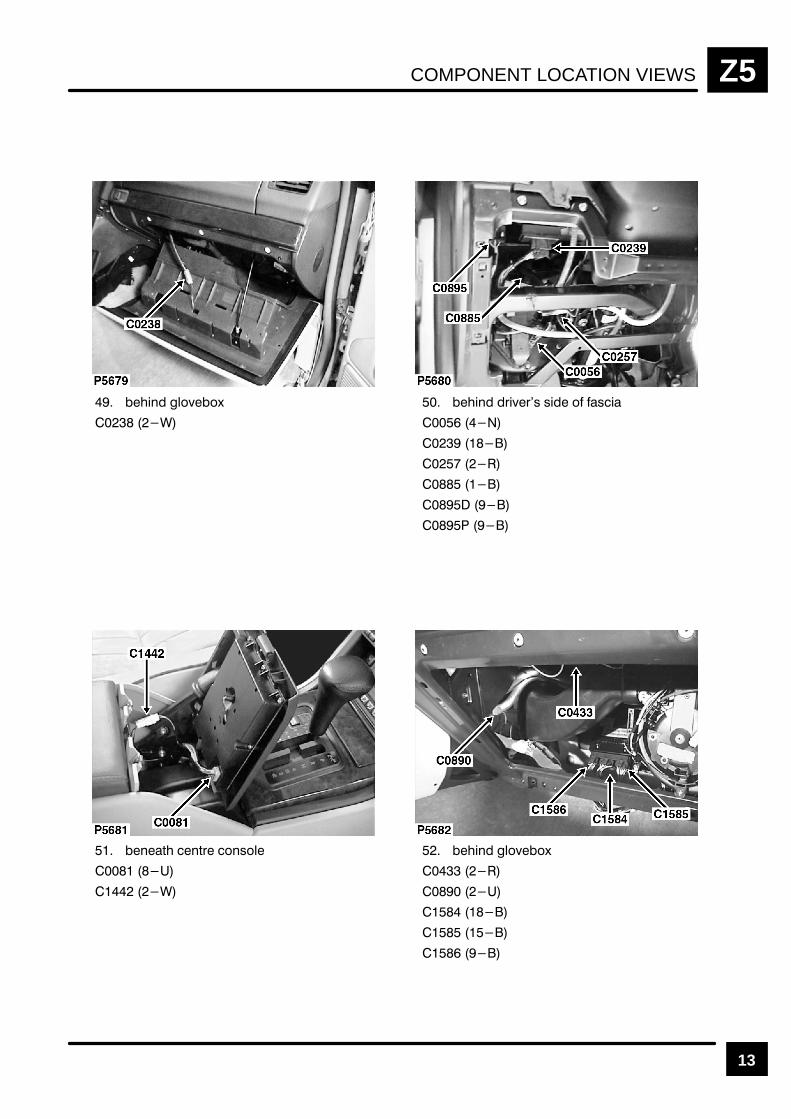
COMPONENT LOCATION VIEWS Z5
13
!# "$($)
!# %!(%& &! $ &!
#' #'% $#&$"
!# "$($)

COMPONENT LOCATION VIEWSZ5
14
$&&"%& & # (!
"' "'% #"&#!
"' "'% #"&#!
" %#
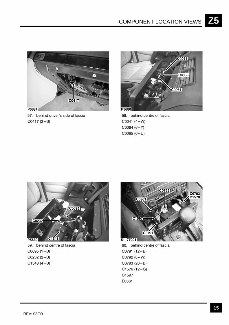
COMPONENT LOCATION VIEWS Z5
15REV: 08/99
$" ! #
$" ! #
"%"# # ! #
$" ! #
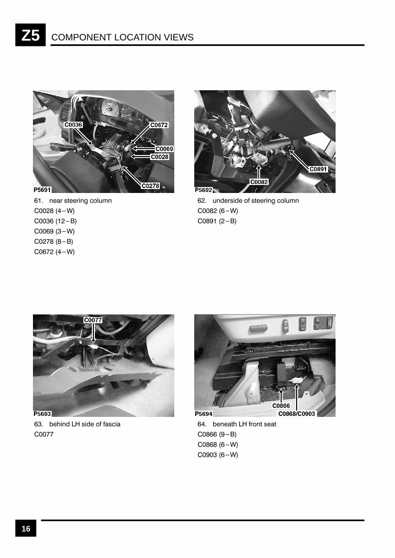
COMPONENT LOCATION VIEWSZ5
16
! "#! $
$!" "#! $
" "
# ! # "#

COMPONENT LOCATION VIEWS Z5
17
"' %#"' &'
"' %#"' &'
"& %)%& &' ' ( &&! +
" #*% $%' # $#&'
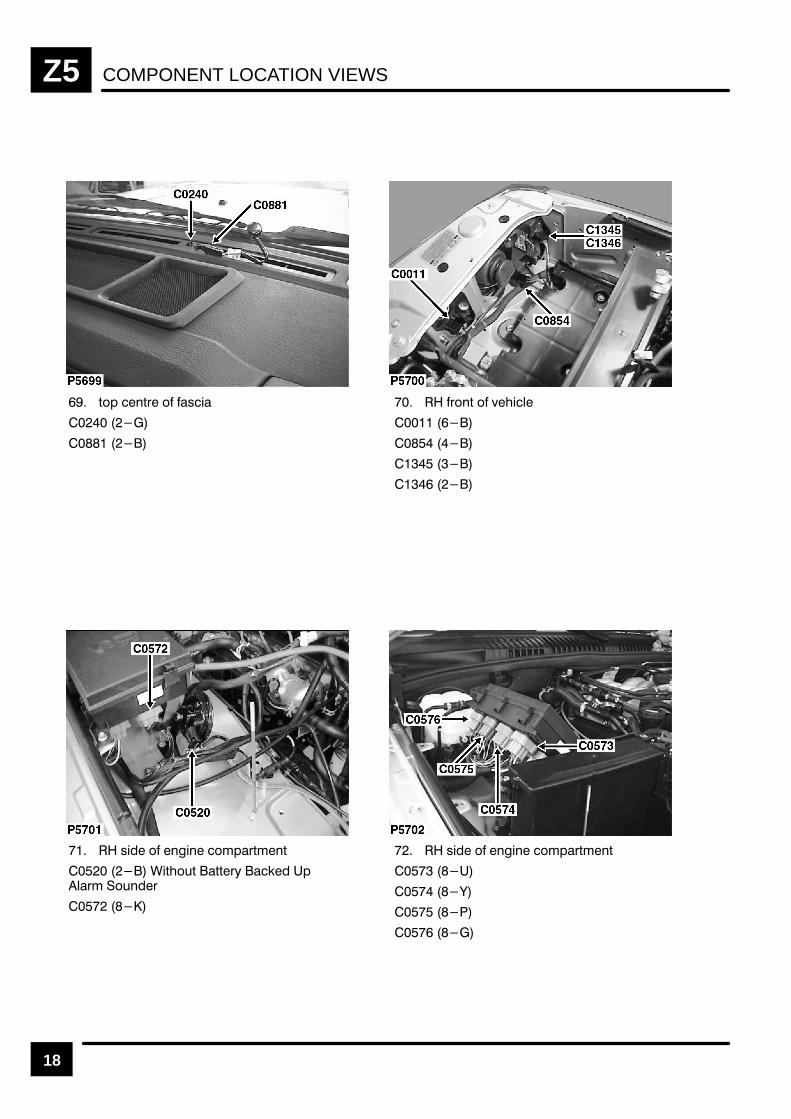
COMPONENT LOCATION VIEWSZ5
18
,() ',* ( +#
*(', ( ."#%
+# ( '!#' (&)*,&',
#,"(-, ,,*/ $ )%*& (-'*
+# ( '!#' (&)*,&',
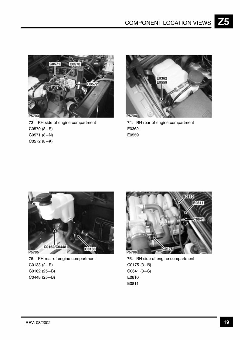
COMPONENT LOCATION VIEWS Z5
19REV: 08/2002
) /+,+
#!# 0
#! -
#!" 1
/+,+
2#"
2#!!%
! /+,+
#"
#""!'
# "!'
) /+,+
#!'
#0
2# #
2#
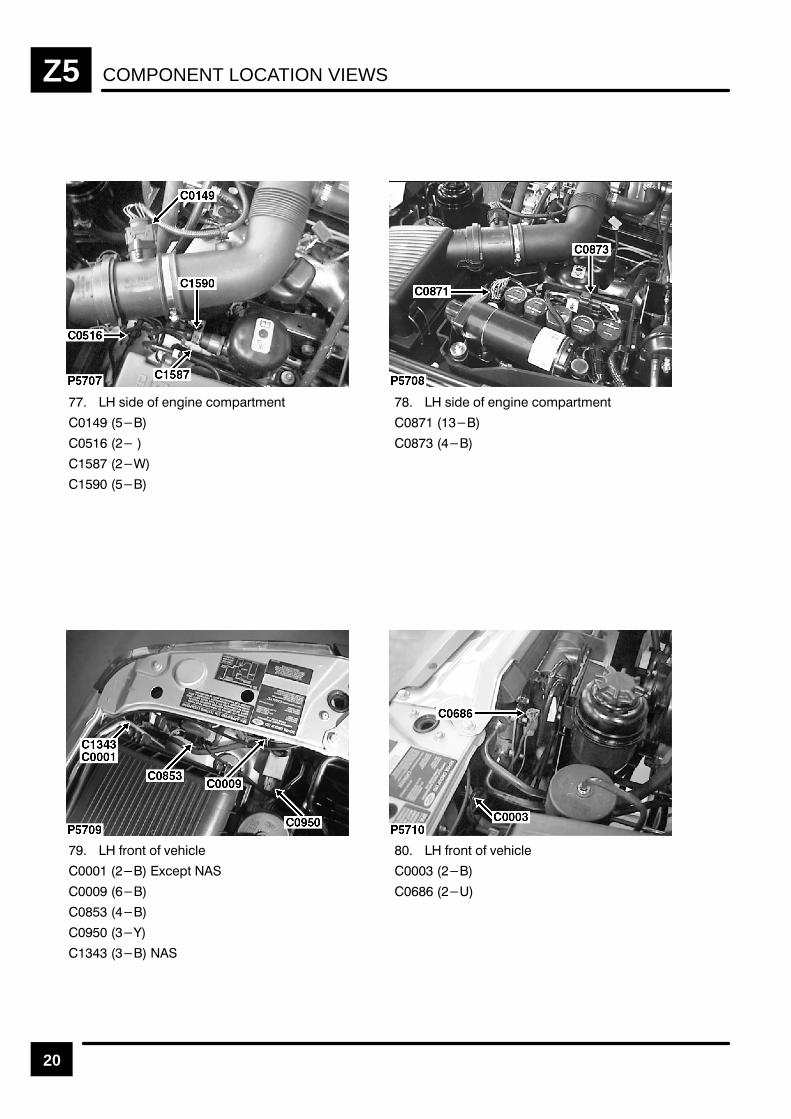
COMPONENT LOCATION VIEWSZ5
20
)" & % "% &$'(*$%*
)" & % "% &$'(*$%*
(&%* & +!"#
,'*
(&%* & +!"#
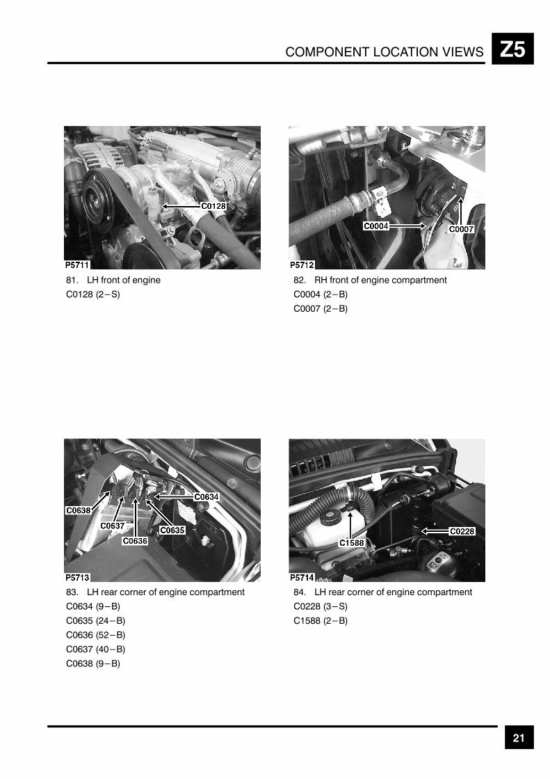
COMPONENT LOCATION VIEWS Z5
21
.
%
&
&"
&& "
&
&
.
"

COMPONENT LOCATION VIEWSZ5
22 REV: 11/99
" +, 0
& #
& #
& # '(
# '(
# '(
# '(
& +, )2 3
#
" (
#
"
+, )2
"/

COMPONENT LOCATION VIEWS Z5
23
!$ %%)*"" )'!# &$"
$) $)' %$(%"
!$ $)' % (!
(! % $!$
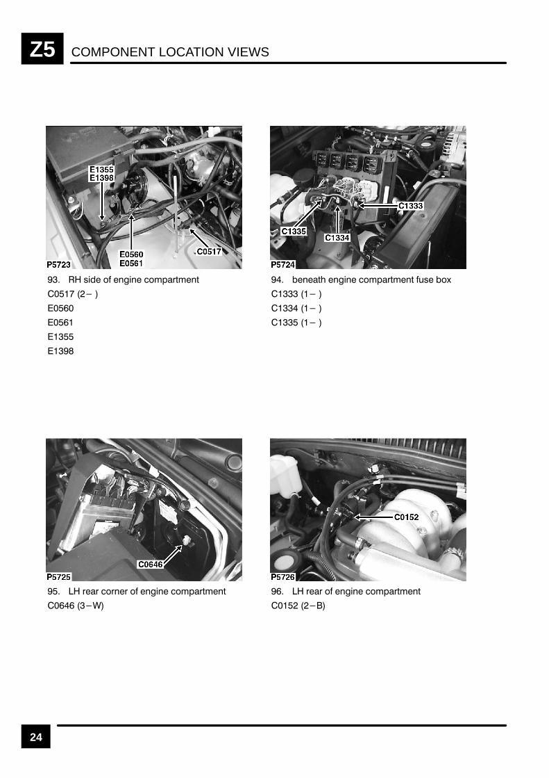
COMPONENT LOCATION VIEWSZ5
24
% " !! " #$& !&
!& !! " #$& !& '% "(
$$ "$!$ " !! " #$& !&
$$ " !! " #$& !&
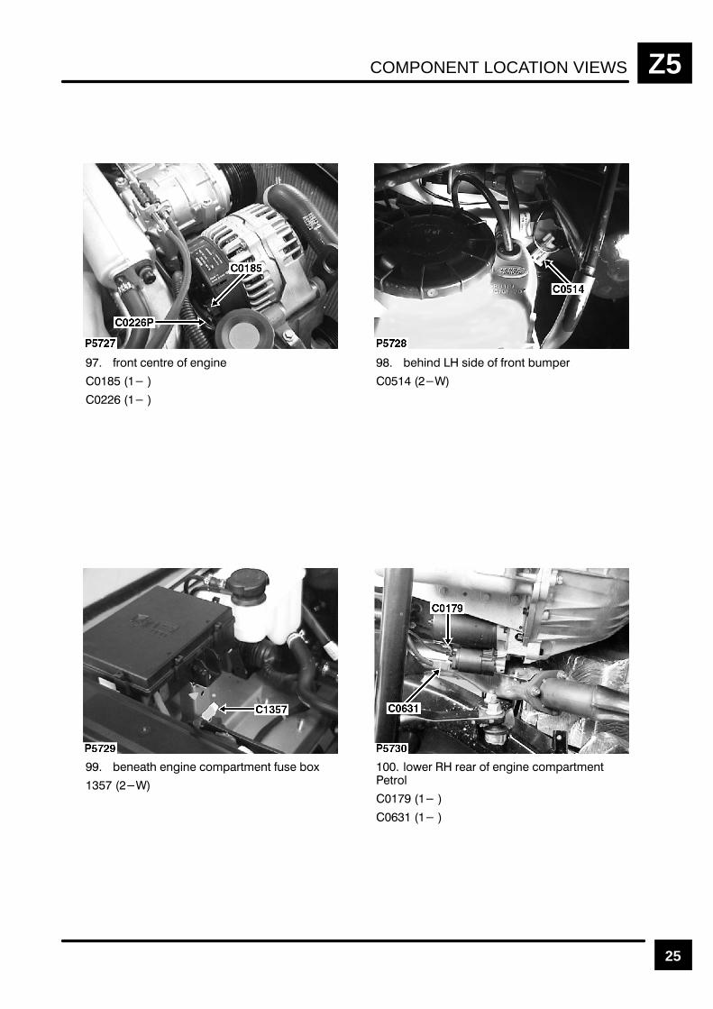
COMPONENT LOCATION VIEWS Z5
25
$"!& !&$ " !!
! % " $"!& ' #$
!& !! " #$& !& '% ")
"($ $$ " !! " #$& !&&$"
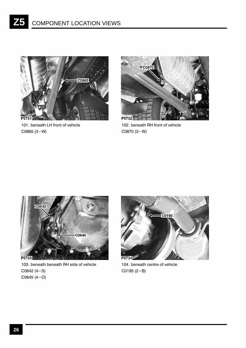
COMPONENT LOCATION VIEWSZ5
26
!% #"!% " &
!% #"!% " &
!% !% $ " &
!% !%# " &

COMPONENT LOCATION VIEWS Z5
27
"& "&$ # ' !
"& $$ # ' !
"& $$ # ' !
!#($ % # " "
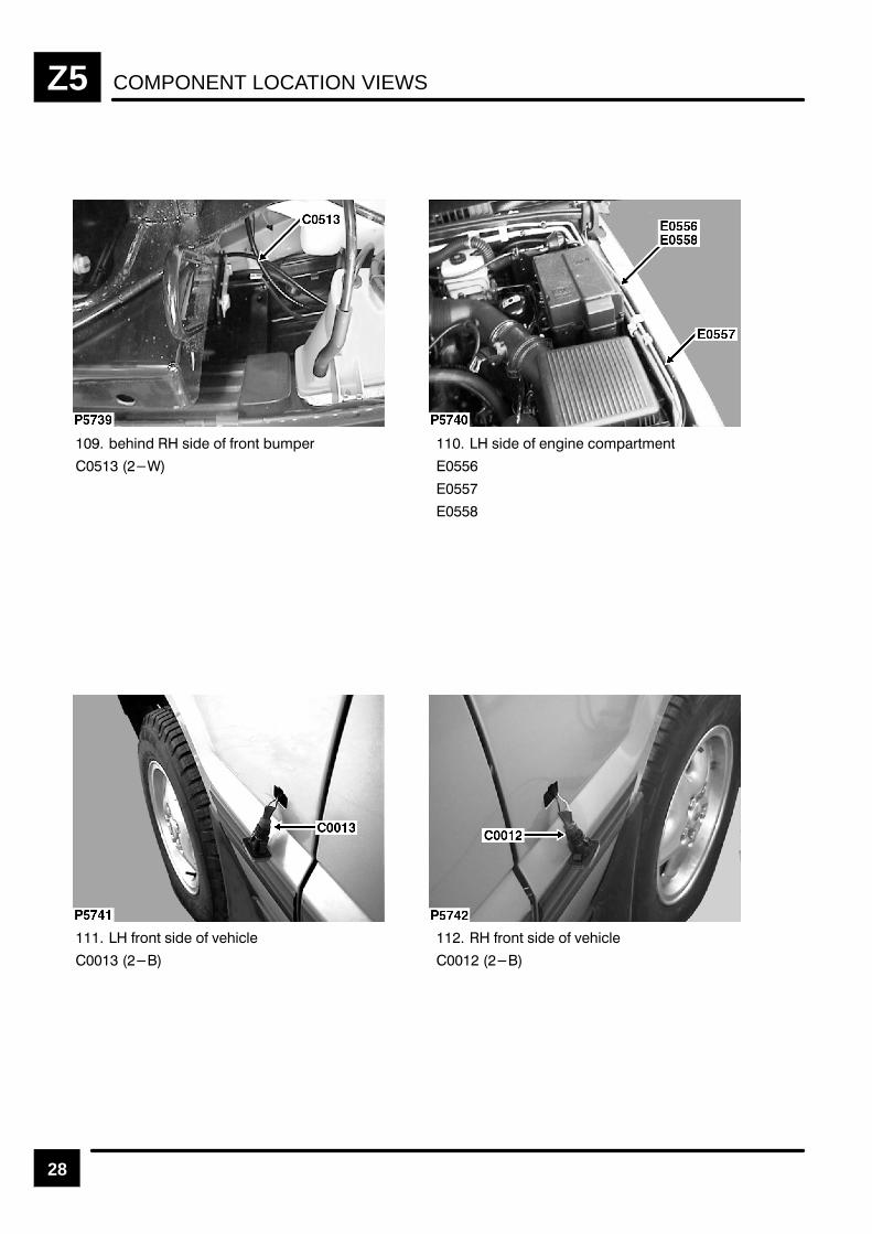
COMPONENT LOCATION VIEWSZ5
28
! % " $"!& ' #$
% " !! " #$& !&
$"!& % " (
$"!& % " (
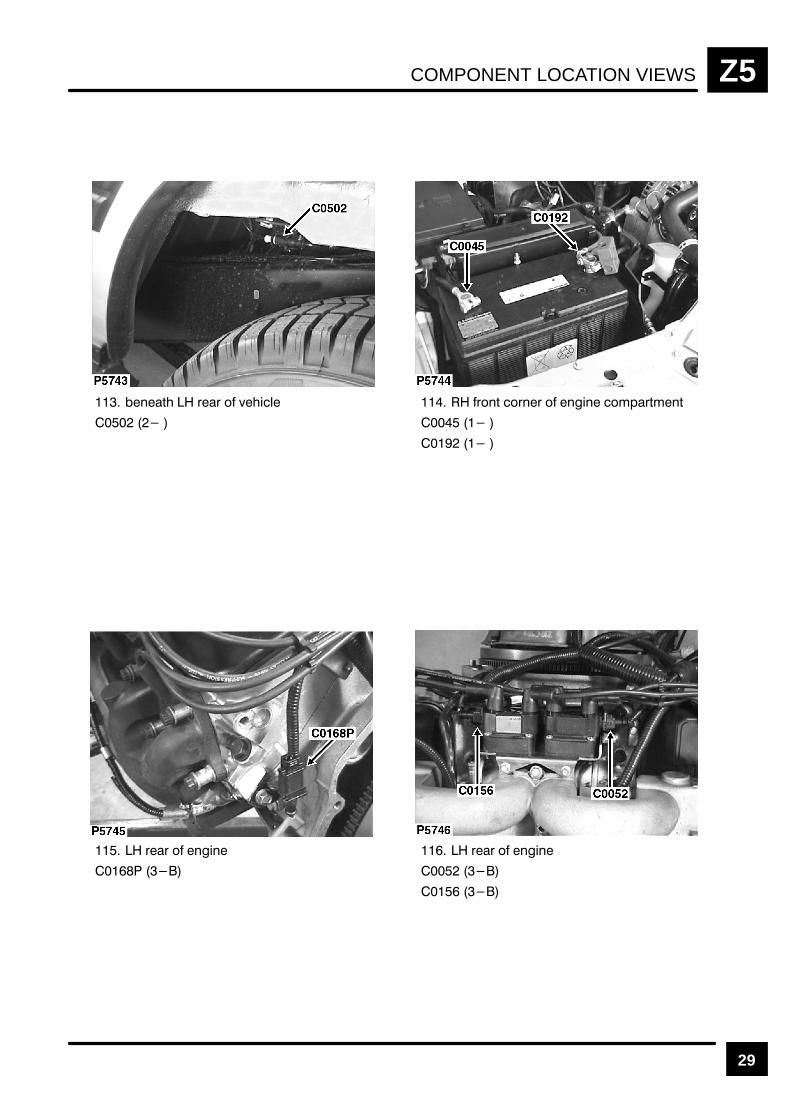
COMPONENT LOCATION VIEWS Z5
29
# "" $
" # "" !"##
""
""

COMPONENT LOCATION VIEWSZ5
30
$ !
$ ! #
$ ! #
%" "" !"$$
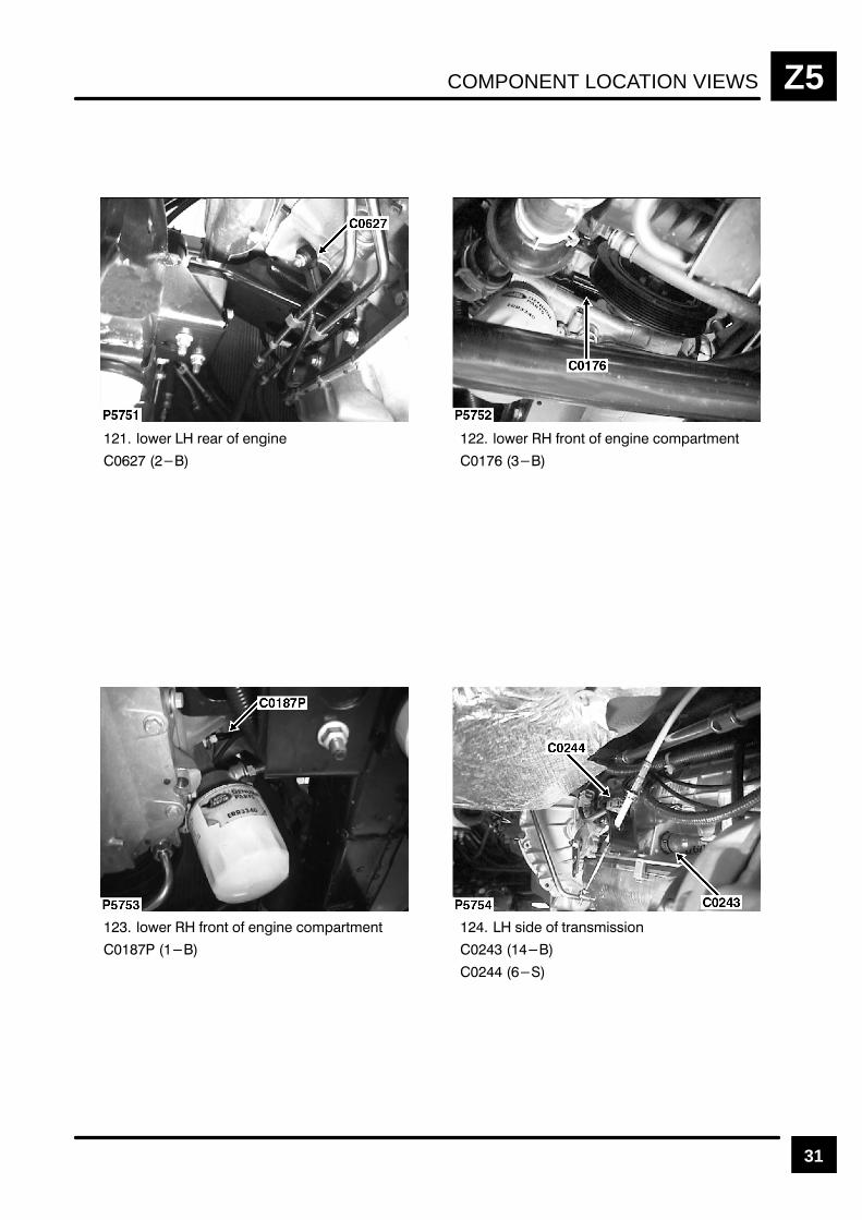
COMPONENT LOCATION VIEWS Z5
31
$! !!
$! !# !##
$! !# !##
" #!"""
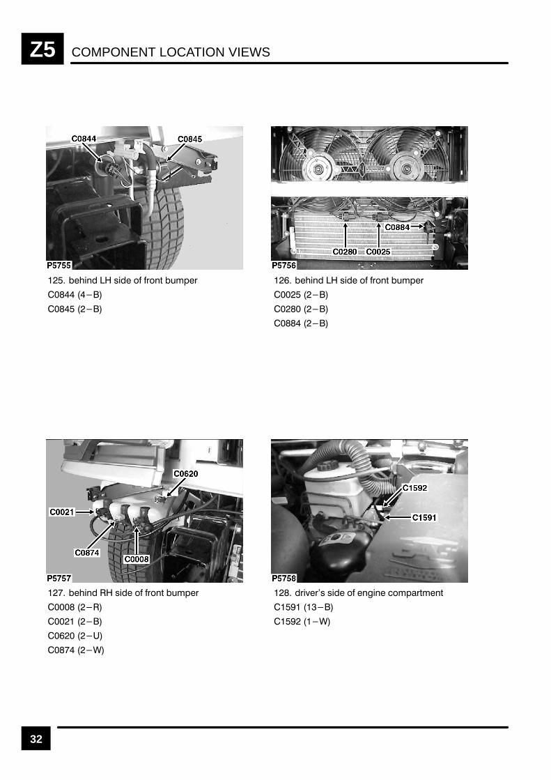
COMPONENT LOCATION VIEWSZ5
32
" & # %#"' (!$%
" & # %#"' (!$%
" & # %#"' (!$%
% )%& & # " " #!$%'!"'
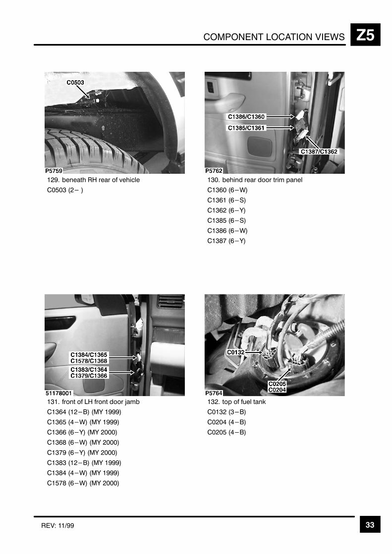
COMPONENT LOCATION VIEWS Z5
33REV: 11/99
+, % ),
"
+,
& &#
& &.
& &(
" &.
& &#
&(
*+
& '(
&" # '(
&& &( '(
& &# '(
&( '(
'(
# '(
" &# '(
4
"

COMPONENT LOCATION VIEWSZ5
34
+,
#
#
.
+, %
#
#
.
" %
"
"
& +, +53
"
$""&3
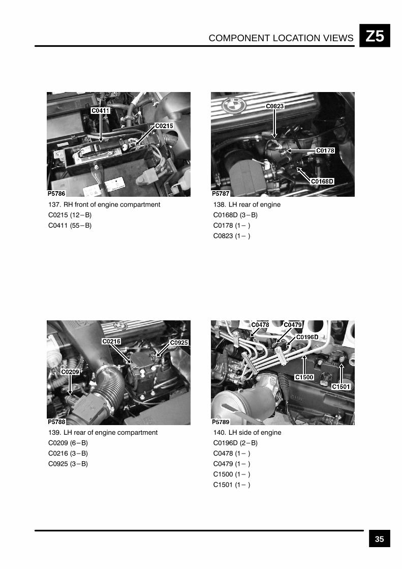
COMPONENT LOCATION VIEWS Z5
35
!# !##
!!
!! !##
"
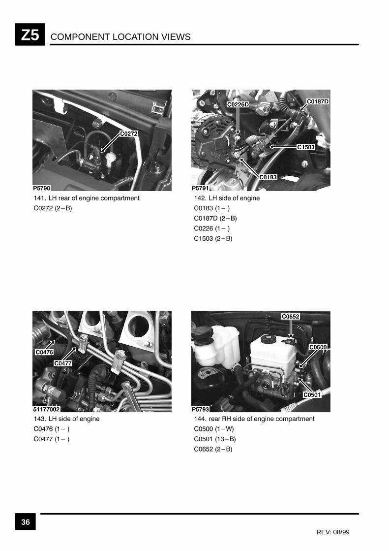
COMPONENT LOCATION VIEWSZ5
36REV: 08/99
"
!! " !##
!! !##
"

COMPONENT LOCATION VIEWS Z5
37
# & )&' ' $ '
& )&' ' $ # # $"%&("#(
# !$)$*
$(($" $ # # '
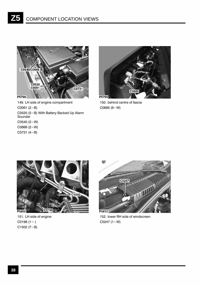
COMPONENT LOCATION VIEWSZ5
38
)! & %!% &$'(*$%*
!* **(- " ' #($&+%(
!% %*( & )!
)! & %!%
#&,( )! & ,!%)(%
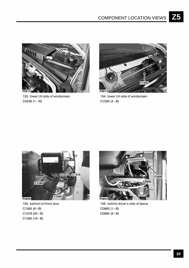
COMPONENT LOCATION VIEWS Z5
39
%! " %"!
%! " %"!
! # !
!$!" " "
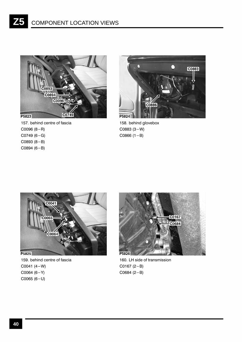
COMPONENT LOCATION VIEWSZ5
40
!$ $(& % '!
!$ "%)%*
!$ $(& % '!
'! % (&$'#!''!%$
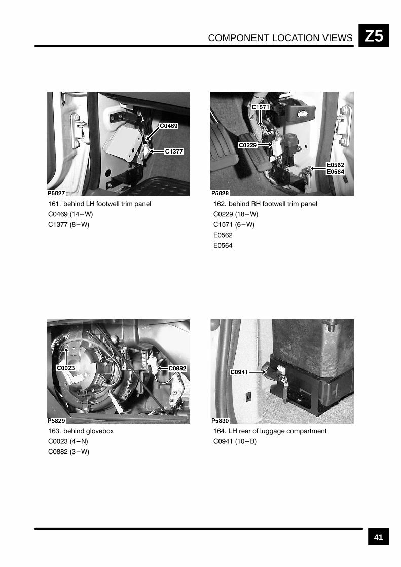
COMPONENT LOCATION VIEWS Z5
41
# $$'*!! '& " %#!
# $$'*!! '& " %#!
# !$)$+
&& $ !( $"%&'"#'

COMPONENT LOCATION VIEWSZ5
42
$!" !" #% !# "#
# #! "
$!" !" #% !# "#
&! " &"!
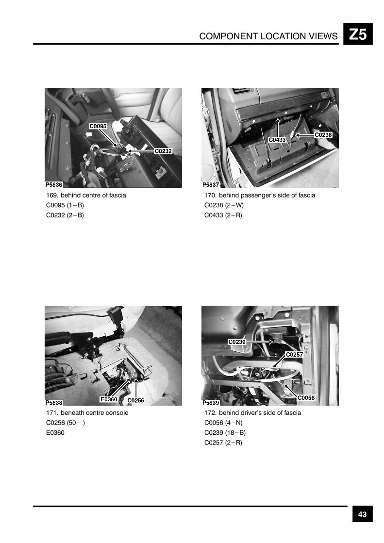
COMPONENT LOCATION VIEWS Z5
43
& +,
"
+, 2
#
%
+,
"& "
$&
+, )2
"& 1
" %
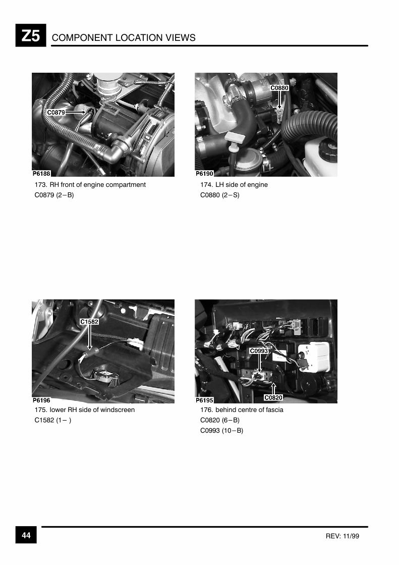
COMPONENT LOCATION VIEWSZ5
44 REV: 11/99
%
.
" 0 % 0
"
& +,
&
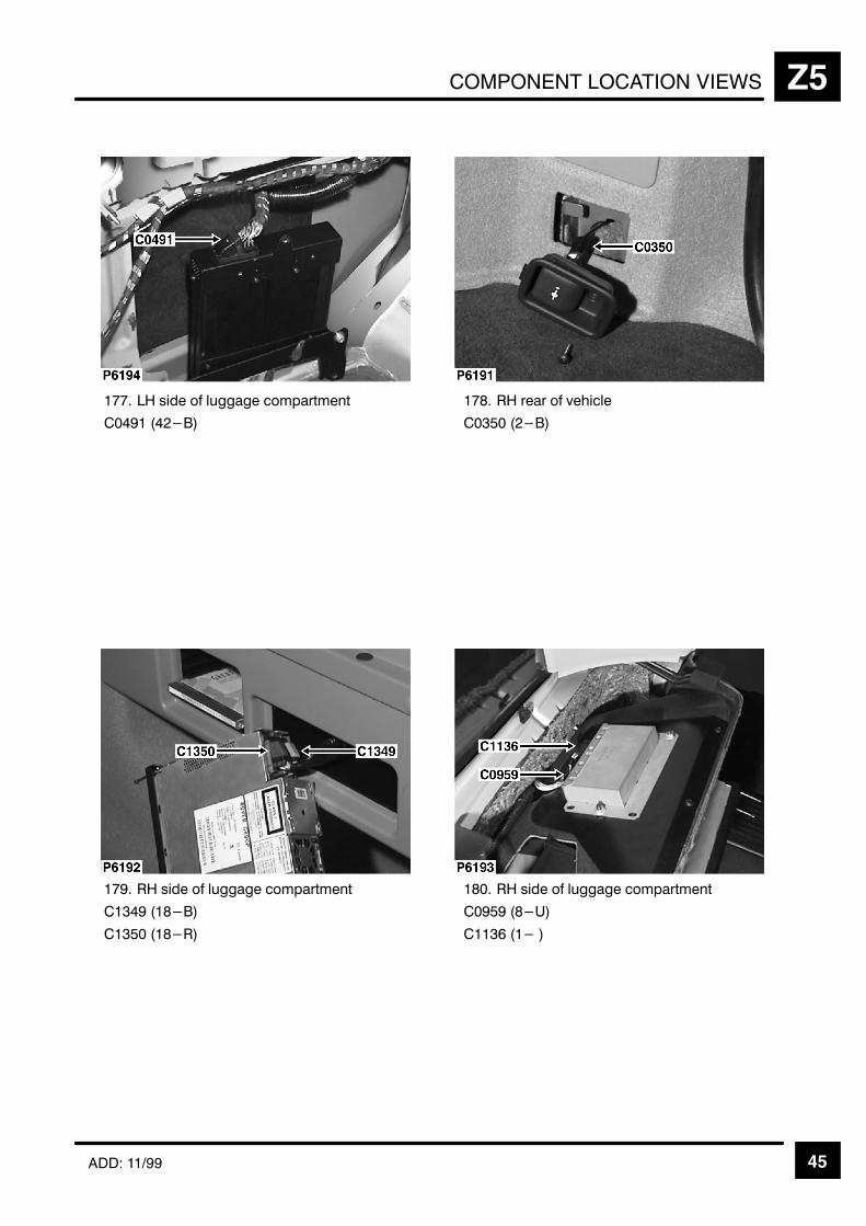
COMPONENT LOCATION VIEWS Z5
45ADD: 11/99
% ),
"
%
" %
%
" /
&

COMPONENT LOCATION VIEWSZ5
46 ADD: 11/2000
181. LH front corner of engine compartment
C1505 (2–R)
C1506 (2–B)
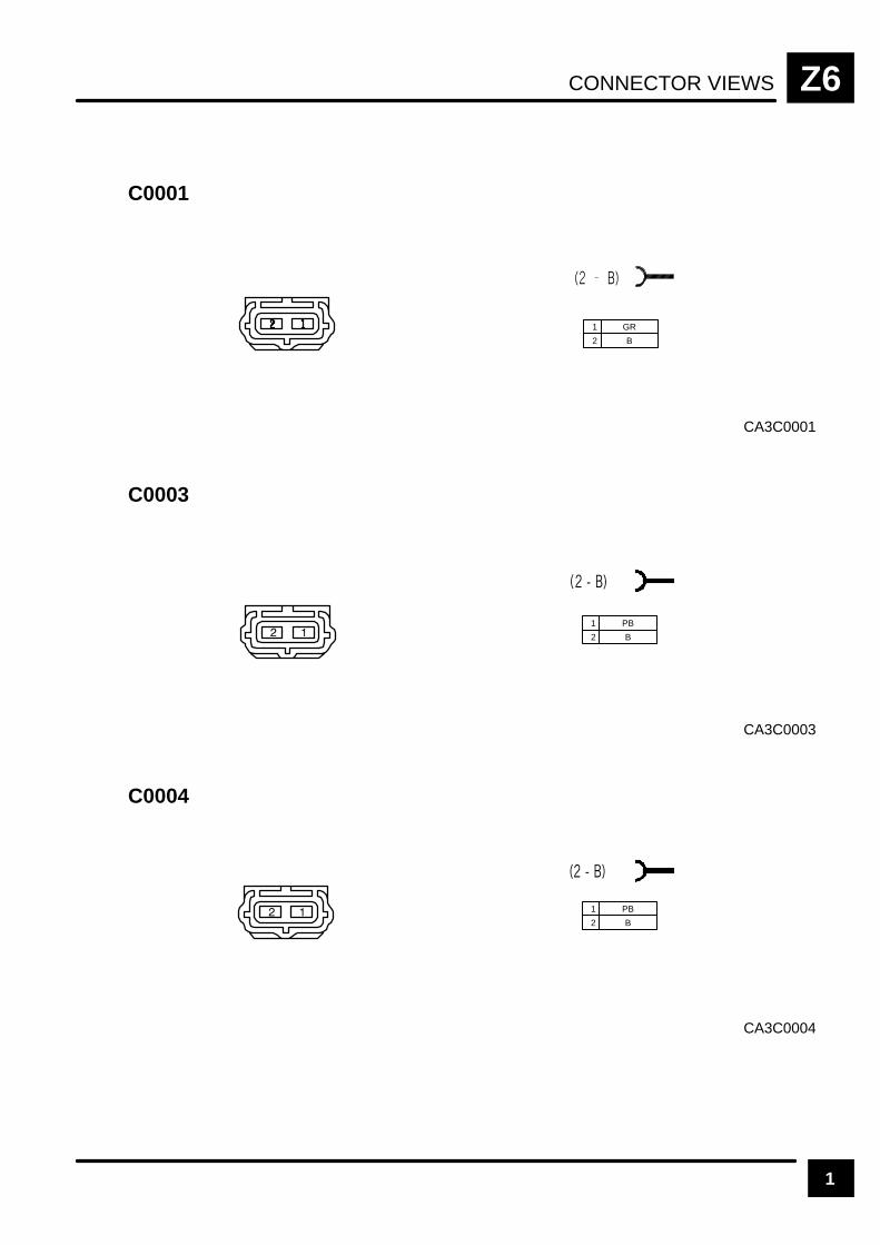
CONNECTOR VIEWS Z6
1
CA3C0001
C0001
1 GR
2 B
CA3C0003
C0003
1 PB
2 B
CA3C0004
C0004
1 PB
2 B
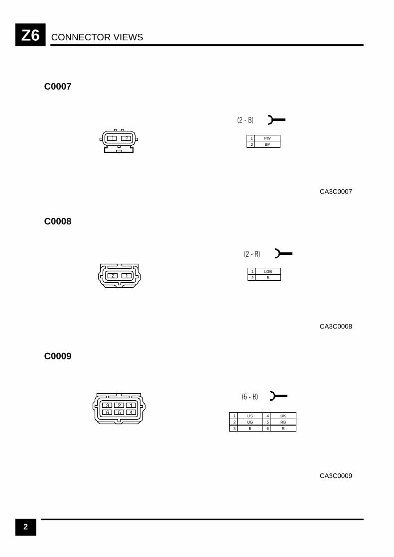
CONNECTOR VIEWSZ6
2
CA3C0007
C0007
1 PW
2 BP
CA3C0008
C0008
1 LGB
2 B
CA3C0009
C0009
1 US
2 UG
3 B
4 UK
5 RB
6 B

CONNECTOR VIEWS Z6
3
CA3C0011
C0011
1 UB
2 UP
3 B
4 UO
5 RW
6 B
CA3C0012
C0012
1 B
2 WG
AFU3698
C0013
1 B
2 RG

CONNECTOR VIEWSZ6
4
CA3C0021
C0021
1 BLG
2 B
CA3C0023
C0023
1 GLG
2 B
3 GY
4 WLG
CA3C0025
C0025
1 BN
2 BN
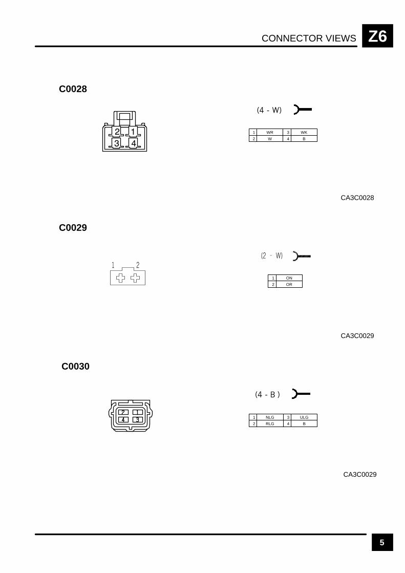
CONNECTOR VIEWS Z6
5
CA3C0028
C0028
1 WR
2 W
3 WK
4 B
CA3C0029
C0029
1 ON
2 OR
CA3C0029
C0030
1 NLG
2 RLG
3 ULG
4 B

CONNECTOR VIEWSZ6
6
CA3C0036
C0036
1 UW
2 US
3 SP
5 RB
6 RLG
7 GW
9
10
11
4 SU 8 B 12 GR
CA3C0040
C0040
1 SR
2
3
7 KR
8
12 WK
4 B
9
13 YK
14 KW
16 N
5 BP
10 14 YG
6
11 WLG 15 LGR
13
CA3C0041
C0041
1 OR
2 RW
3 B
4 U
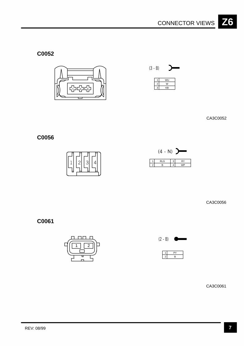
CONNECTOR VIEWS Z6
7REV: 08/99
CA3C0052
C0052
1 WU
2 W
3 KB
CA3C0056
C0056
1 RLG
2 B
3 RY
4 WP
CA3C0061
C0061
21
1 PY
2 B
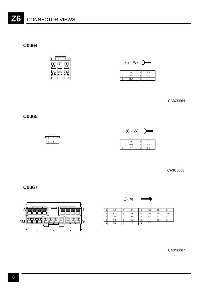
CONNECTOR VIEWSZ6
8
CA3C0064
C0064
1 B
2 RN
3 RW
4 B,B
5 RU
6
CA3C0065
C0065
1 B
2 RW
3 YR
4 B,B
5 RY
6 B, B
CA3C0067
C0067
1 BG
2 PY
2 OY
5 BP
6 W
7 BY
10 PG
3 PB 8 GU
11 YB
12 BS
13 N
15 K
16 LGR
17 G
4 PN 9 YP 14 GP
18 G

CONNECTOR VIEWS Z6
9
CA3C0069
C0069
1 PN
2
3 PY
CA3C0075
C0075
1 W
2 YP
3 GP
CA3C0076
C0076
1 P
2 PR
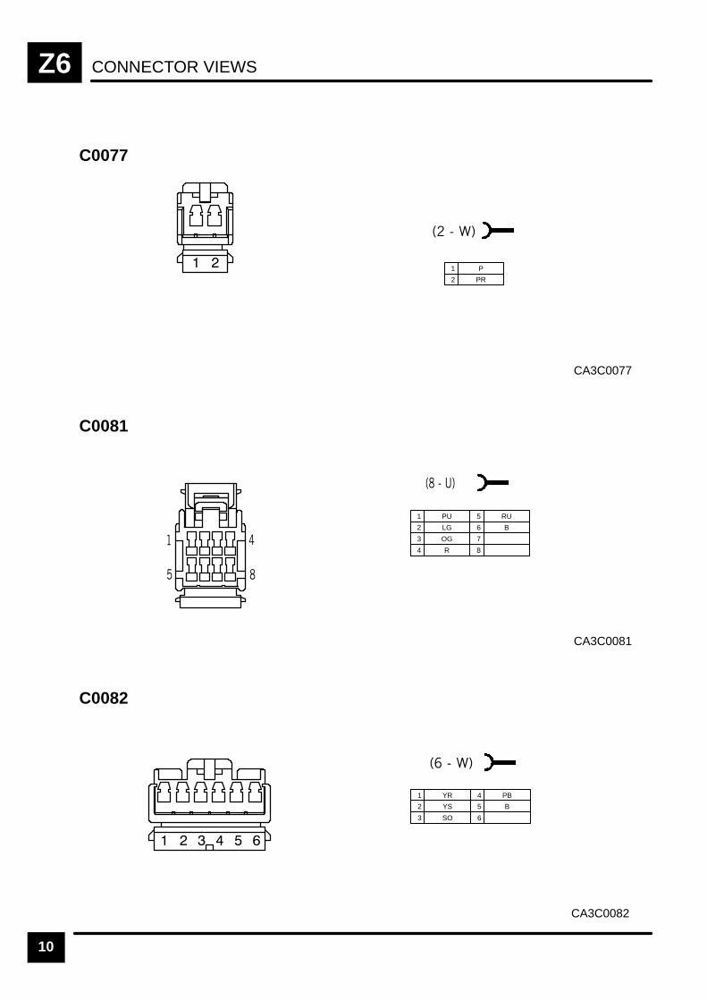
CONNECTOR VIEWSZ6
10
CA3C0077
C0077
1 P
2 PR
CA3C0081
C0081
1 PU
2 LG
3 OG
4 R
5 RU
6 B
7
8
CA3C0082
C0082
1 YR
2 YS
3 SO
4 PB
5 B
6
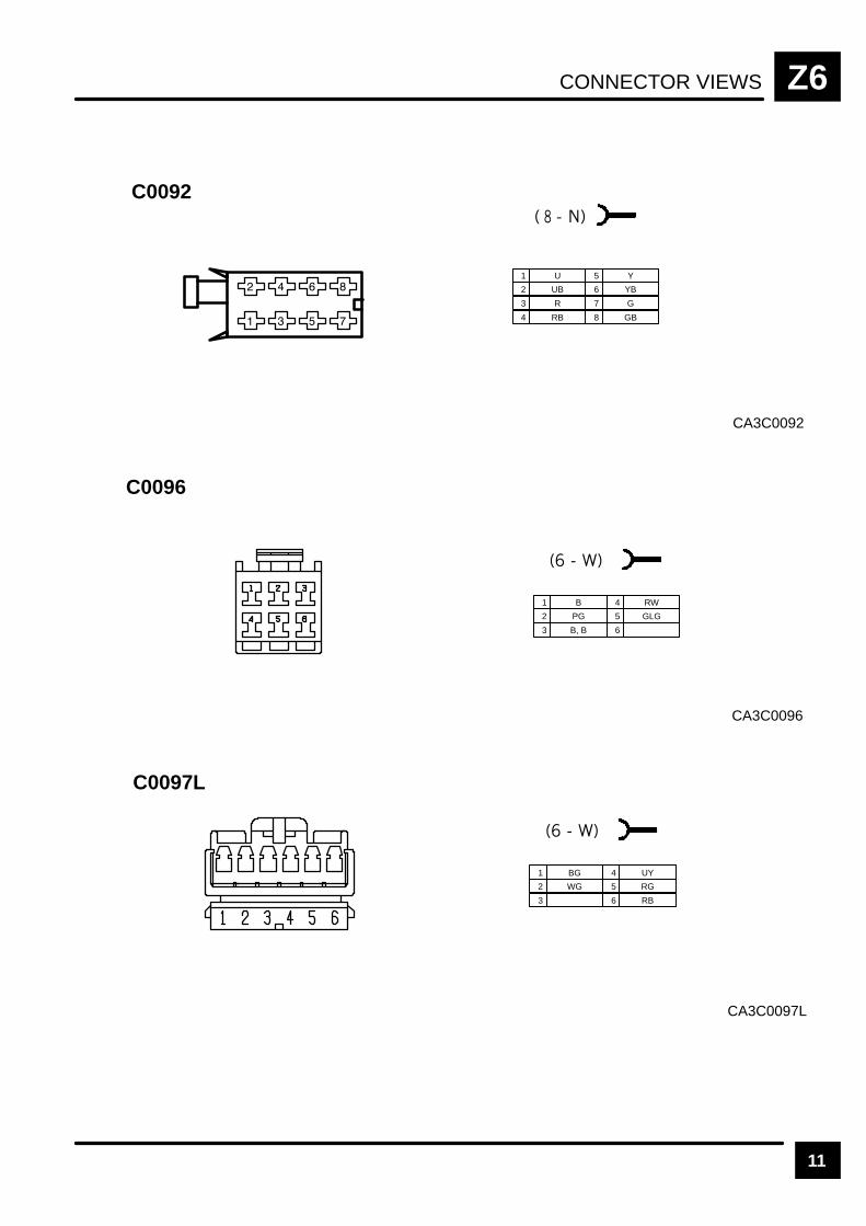
CONNECTOR VIEWS Z6
11
CA3C0092
C0092
1 U
2 UB
3 R
4 RB
5 Y
6 YB
7 G
8 GB
CA3C0096
C0096
1 B
2 PG
3 B, B
4 RW
5 GLG
6
CA3C0097L
C0097L
1 BG
2 WG
3
4 UY
5 RG
6 RB

CONNECTOR VIEWSZ6
12
CA3C0157R
C0157R
1 WO, WO
2 BY
3 WO
4 W
5
"#
"
!
%
#
"
!
%
"""
"!
"
"
CA3C0162
C0162
1 B
2 WLG
3 GB
6 BN
7 GK
4 BG
7 NG
9 RB
9 BR
12 G
5 BS
8 R
10 NG
13 UN
14 Y
8 RB
11 W
15 WU
16 YK
17 K
18 W
19 YB
20 S
21 YN
22 YB
23 WN
24 GU
25 NY
CA3C0167
C0167
1 GN
2 B
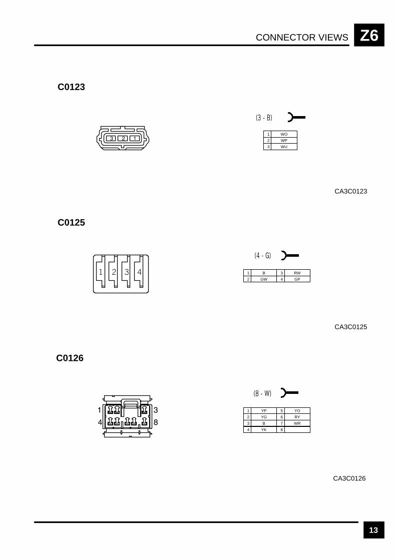
CONNECTOR VIEWS Z6
13
CA3C0123
C0123
1 WO
2 WP
3 WU
CA3C0125
C0125
1 B
2 GW
3 RW
4 GP
CA3C0126
C0126
1 YP
2 YG
3 B
4 YK
5 YO
6 RY
7 WR
8
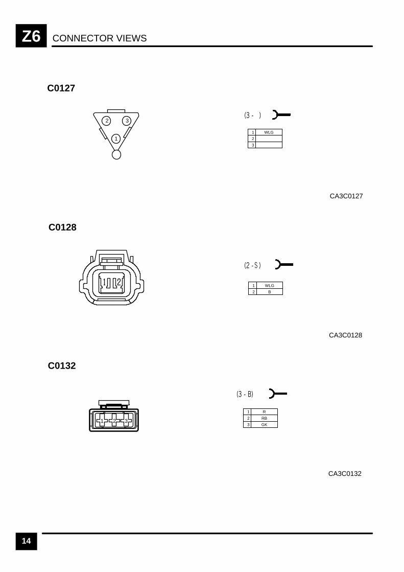
CONNECTOR VIEWSZ6
14
CA3C0127
C0127
1 WLG
2
3
1
2 3
CA3C0128
C0128
1 WLG
2 B
CA3C0132
C0132
1 R
2 RB
3 GK1 2 3
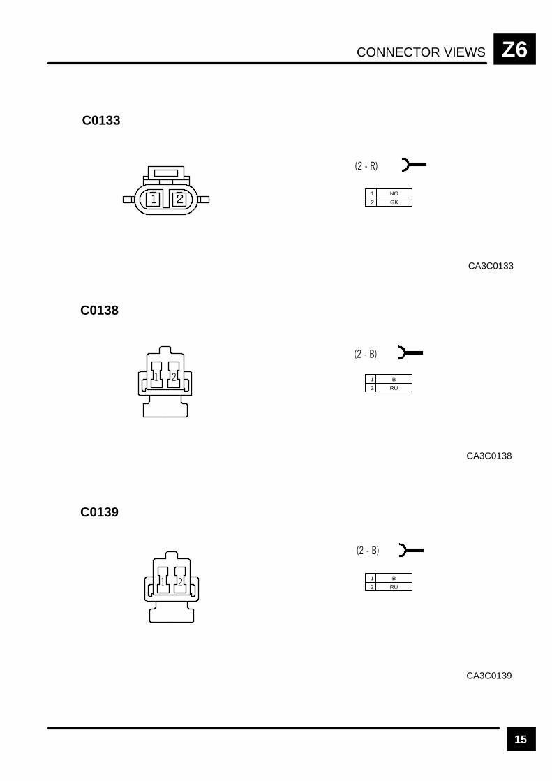
CONNECTOR VIEWS Z6
15
CA3C0133
C0133
1 NO
2 GK
CA3C0138
C0138
1 B
2 RU
CA3C0139
C0139
1 B
2 RU

CONNECTOR VIEWSZ6
16
CA3C0149
C0149
1 SLG
2 NK
3 RB
4 R
5 UG
CA3C00C152
C0152
1 NR
2 NK
CA3C0154L
C0154L
1 WO, WO
2 BY
3 WO
4 W
5
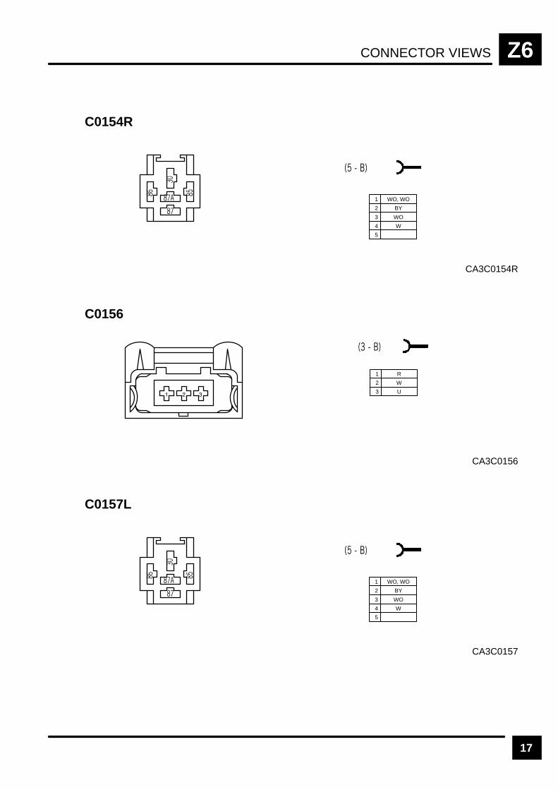
CONNECTOR VIEWS Z6
17
CA3C0154R
C0154R
1 WO, WO
2 BY
3 WO
4 W
5
CA3C0156
C0156
1 R
2 W
3 U
CA3C0157
C0157L
1 WO, WO
2 BY
3 WO
4 W
5
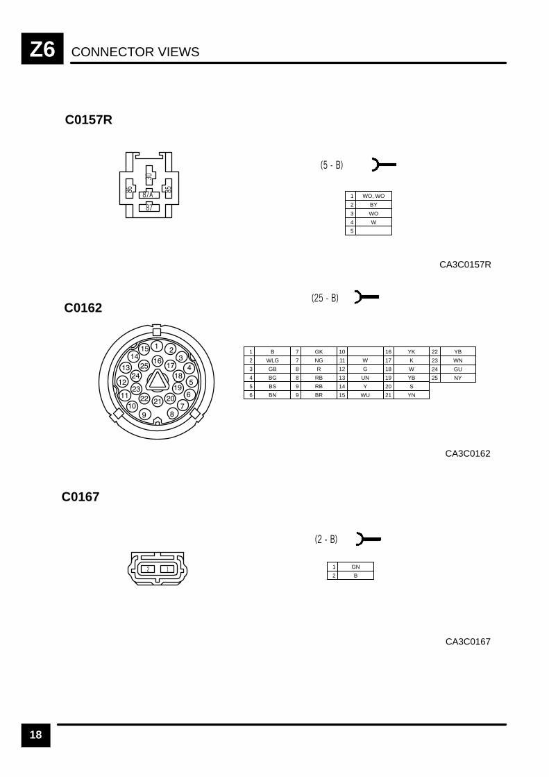
CONNECTOR VIEWSZ6
18
CA3C0157R
C0157R
1 WO, WO
2 BY
3 WO
4 W
5
CA3C0162
C0162
1 B
2 WLG
3 GB
6 BN
7 GK
4 BG
7 NG
9 RB
9 BR
12 G
5 BS
8 R
10
13 UN
14 Y
8 RB
11 W
15 WU
16 YK
17 K
18 W
19 YB
20 S
21 YN
22 YB
23 WN
24 GU
25 NY
CA3C0167
C0167
1 GN
2 B
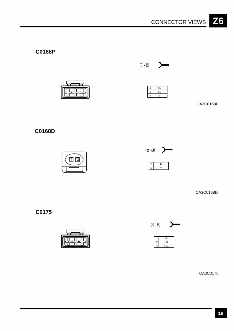
CONNECTOR VIEWS Z6
19
CA3C0168P
C0168P
1 BY
2 KB
3 B1 2 3
CA3C0168D
C0168D
2 B
1 B
2 Y
CA3C0175
C0175
1 R
2 RB
3 YLG
1 2 3
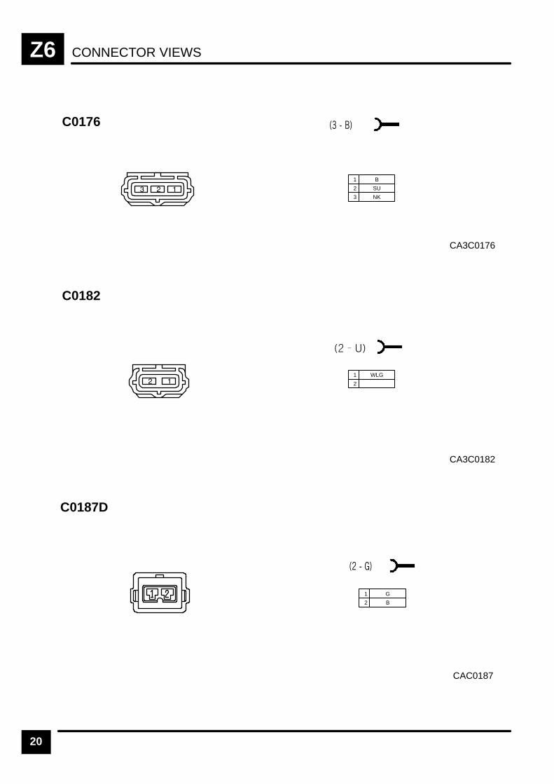
CONNECTOR VIEWSZ6
20
CA3C0176
C0176
1 B
2 SU
3 NK
CA3C0182
C0182
1 WLG
2
CAC0187
C0187D
1 G
2 B
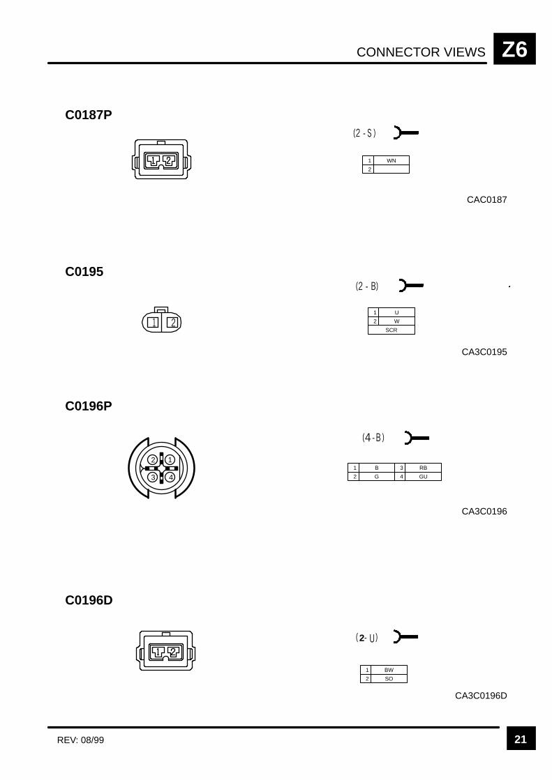
CONNECTOR VIEWS Z6
21REV: 08/99
CA3C0195
C0195
1 U
2 W
SCR
CA3C0196
C0196P
3 4
121 B
2 G
3 RB
4 GU
CA3C0196D
C0196D
2
1 BW
2 SO
C0187P
1 WN
2
CAC0187

CONNECTOR VIEWSZ6
22
CA3C0203
C0203
1 B
2 YP
3 GP
6 NY
7 B
4 BG 9 YS
12 G
5 BS
8 W
10 SW
13 UN
14 Y
11 NG
15 WU
16 GR
17 PR
18 BY
19 YO
20 S
21 SR
22 YO
23 WN
24 GU
25 NY
CA3C0204
C0204
1 GB
2 BP
3 B
4 WU
CA3C0205
C0205
1 WU
2 GB
3 BP
4 B
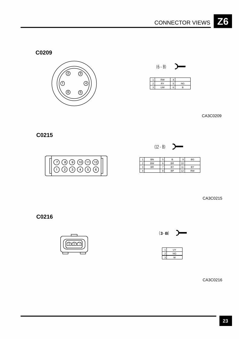
CONNECTOR VIEWS Z6
23
CA3C0209
C0209
1 RW
2 RY
3 UW
4
5 NG
6 B
CA3C0215
C0215
1 BN
2 BW
3 BR
5 B
6 BR
7 BY
9 BG
10
11 BY
4 8 BP 12 RW
3 B
CA3C0216
C0216
1 UY
2 NG
3 W
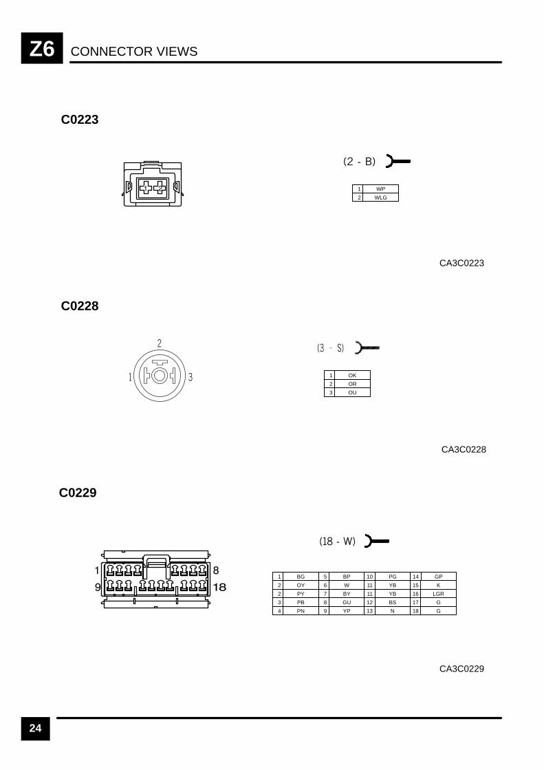
CONNECTOR VIEWSZ6
24
CA3C0223
C0223
1 WP
2 WLG
CA3C0228
C0228
1 OK
2 OR
3 OU
CA3C0229
C0229
1 BG
2 OY
2 PY
5 BP
6 W
7 BY
10 PG
3 PB 8 GU
11 YB
11 YB
12 BS
15 K
16 LGR
17 G
4 PN 9 YP
14 GP
18 G13 N
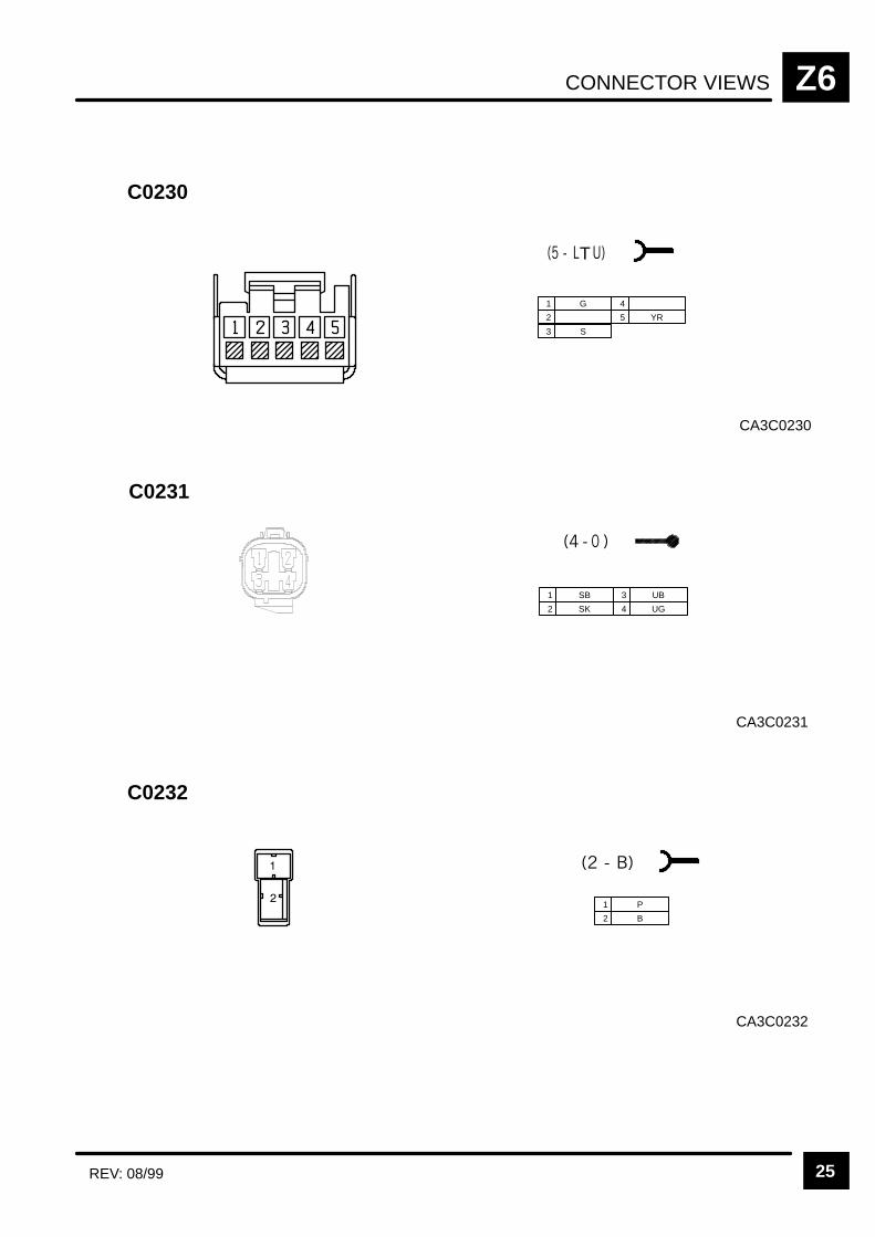
CONNECTOR VIEWS Z6
25REV: 08/99
CA3C0230
C0230
T
1 G
2
3 S
4
5 YR
CA3C0231
C0231
1 SB
2 SK
3 UB
4 UG
CA3C0232
C0232
1 P
2 B
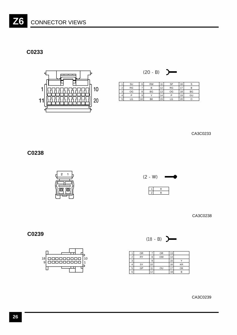
CONNECTOR VIEWSZ6
26
CA3C0233
C0233
1 SU
2 RG
3 OG
6 RW
7 B
8 BG
11 SP
4 P 9 Y
12 RG
13 OG
14 P
16 S
17 B
18 BG
5 LG 10 BK 15 LG
19 GU
20 O
CA3C0238
C0238
1 R
2 B
CA3C0239
C0239
1 OR
2 RY
3
7 OR
8 OW
12
4 SY
9
13
14
17 OK
18 B
5 GP
10
15 Y
6
11 OU
16 KR
101
189

CONNECTOR VIEWS Z6
27
CA3C0240
C0240
1 SR
2 B
CA3C0243
C0243
B OP
D Y
E K
L OLG
M SO
H OG
K OW
SCR
C0244
1 UB
2 UP
3 UG
4
5
6 BS
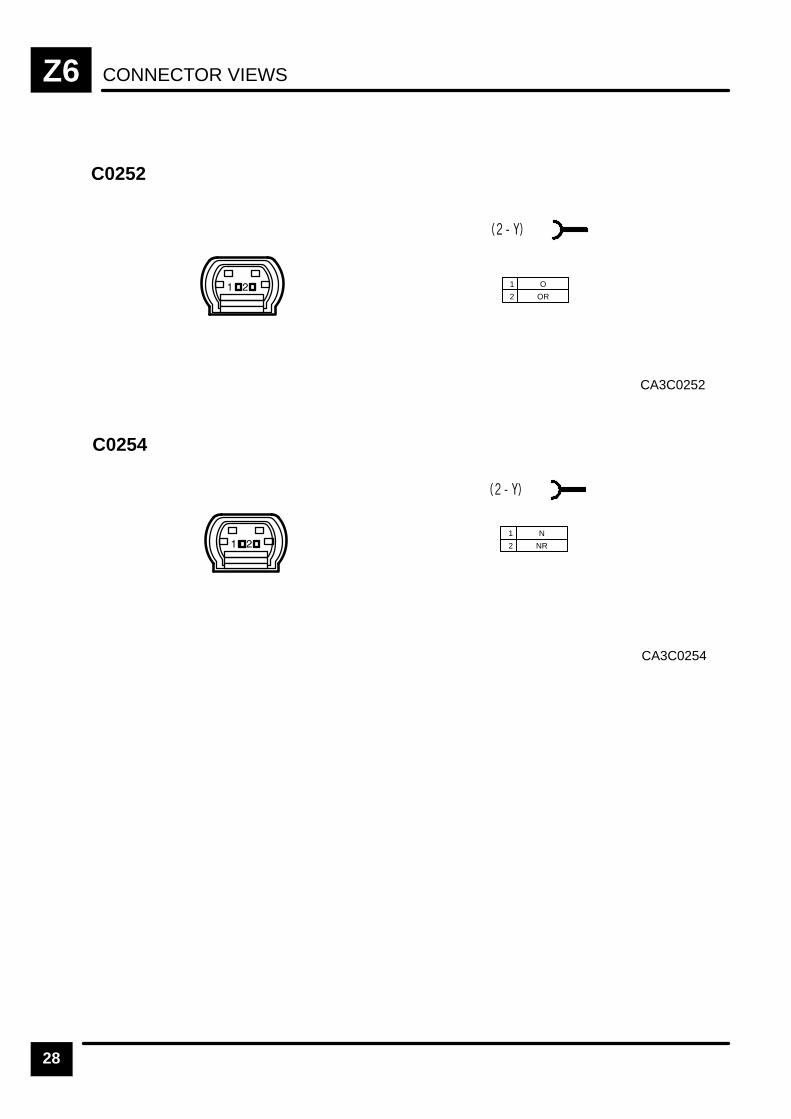
CONNECTOR VIEWSZ6
28
CA3C0252
C0252
1 O
2 OR
1 N
2 NR
CA3C0254
C0254
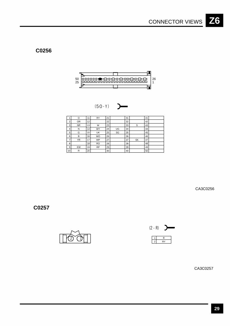
CONNECTOR VIEWS Z6
29
CA3C0256
C0256
5025
261
21
22
23
24 UG
25 SG
26
27
28
29
30
31
32
33 S
34
35
36
37 SK
38
39
40
41
42
43
44
45
46
47
48
49
50
1 O
2 OR
3 NR
7 YR
8
9 KW
4 N
10 R
5 G
6 B
13 W
14 WY
15 UK
16 WO
19 RP
20
11 RY
17 WP
12
18 RO
CA3C0257
C0257
1 R
2 RY

CONNECTOR VIEWSZ6
30
CA3C0262
C0262
1 B
2 WB
CA3C0272
C0272
1 U
2 UB
3 PW
4 BO
5 BK
6 BG
CA32C0272
C0272
1 RW
2 B

CONNECTOR VIEWS Z6
31
CA32C0277
C0277
1 WLG
2
CA3C0278
C0278
1 OB
2 RLG
3 OP
4 LGO
5 ULG
6 B
7 WG
8 LGB
CA3C0280
C0280
1 BR
2 B

CONNECTOR VIEWSZ6
32
CA3C302L
C0302L
1 B
1 O
2
3 O
3 B 6 PW
4 PW
4 K
5 OK
6 K
CA3C302R
C0302R
1 B
1 O
2
3 O
3 B 6 PW
4 PW
4 K
5 OK
6 K
CA3C0304L
C0304L
1 S
2 BG
3 SO
4 YB
5 YR
6 B
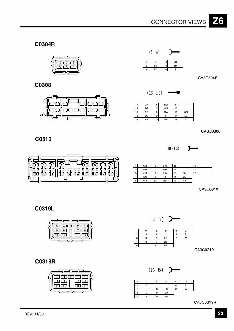
CONNECTOR VIEWS Z6
33REV: 11/99
CA3C304R
C0304R
1 S
2 BG
3 SO
4 YB
5 YR
6 B
CA3C0310
C0310
1 GR
2 RG
3 GB
6 BW
7 WR
8 RW
11
4 BG 9 R
12
13 GN
14 SB
16
17
18
5 WB 10 RB 15 YR
CA3C0319L
C0319L
1 G
2 S
3 R
6 B
7
8 LG
10 BR
11 O
4 U 8 UB
12 P
13 W
5 Y
CA3C0319R
C0319R
1 G
2 S
3 R
6 B
7
8 LG
10 BR
11 O
4 U 9 UB
12 P
13 W
5 Y
CA3C0308
C0308
1 GR
2 RG
3 GB
6 BW
7 WR
8 RW
11
4 BG 9 R
12
13 GN
14 SB
5 WB 10 RB 15 Y
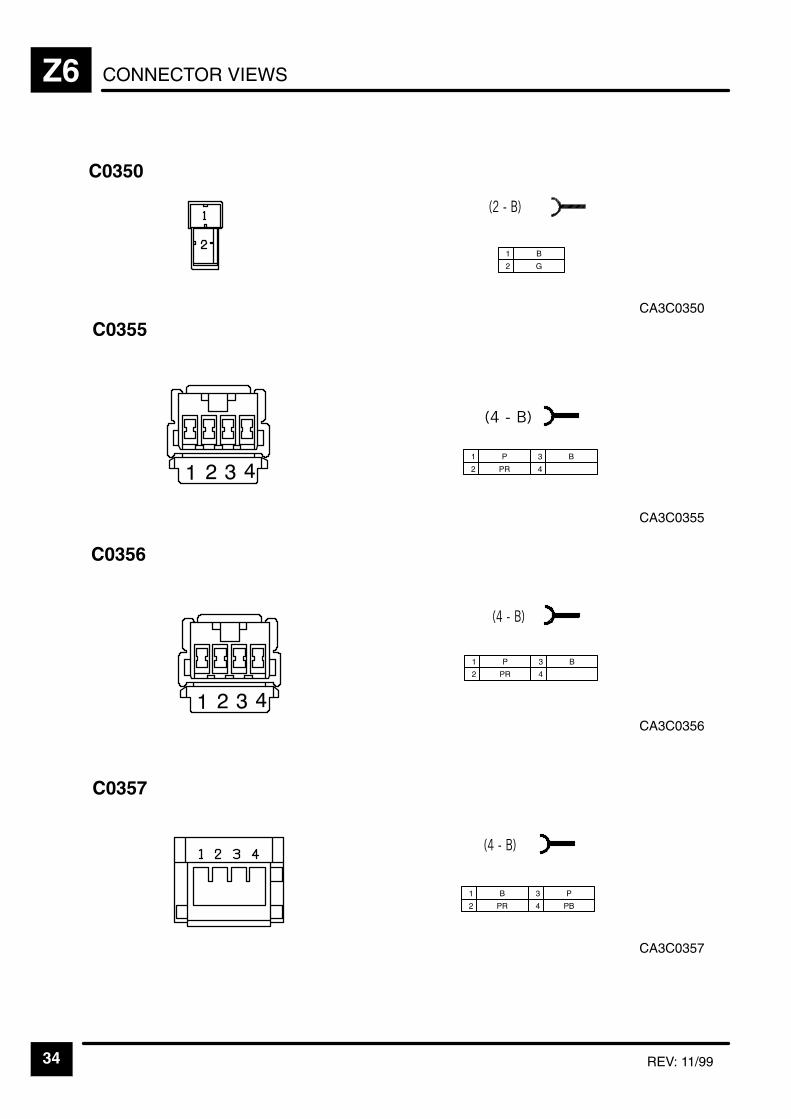
CONNECTOR VIEWSZ6
34 REV: 11/99
CA3C0350
C0350
1 B
2 G
CA3C0355
C0355
1 P
2 PR
3 B
4
CA3C0356
C0356
1 P
2 PR
3 B
4
CA3C0357
C0357
1 B
2 PR
3 P
4 PB

CONNECTOR VIEWS Z6
35REV: 11/99
CA3C0358
C0358
1 OR
2 B
3 P
CA3C0359
C0359
1 RY
2 B
3 YK
4
CA3C369L
C0369L
1 BW
1 YB
1 YW
2 WB
2 Y
2 WY
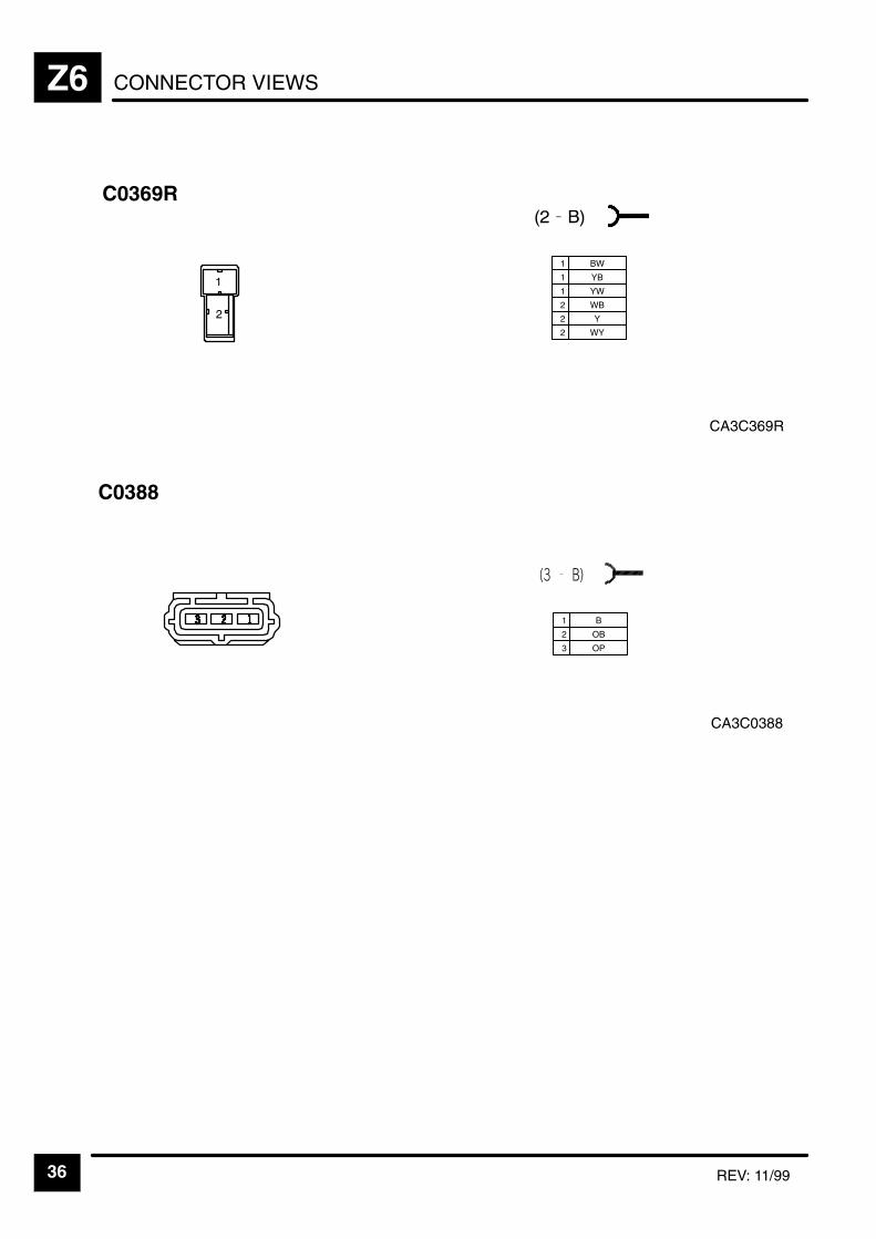
CONNECTOR VIEWSZ6
36 REV: 11/99
CA3C369R
C0369R
1 BW
1 YB
1 YW
2 WB
2 Y
2 WY
CA3C0388
C0388
1 B
2 OB
3 OP
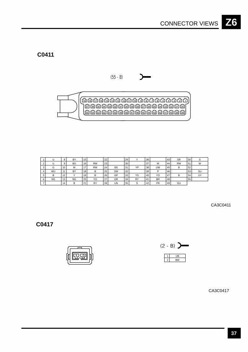
CONNECTOR VIEWS Z6
37
CA3C0411
C0411
1 U
2 U
3 G
7
8 BY
9 BG
13 NG
4 WU
10 W
14 B
15
16 RW
19 B
20 YO
21 RY
5 B
11 BY
17 RW
22
23
6 NG
12 Y
18 B
24 BS
25 SW
26 GP
29 Y
30
31 YP
27 GR
32
33 YS
28 UN
34 RY
35 S
36
37 W
38 UW
39 P
40 YO
41 BR
42 PR
43 SR
44 RW
45 B
46
47 B
48
49 GU
50 S
51 W
52
53 SU
54 UY
55
CA3C0417
C0417
1 UB
2 BW

CONNECTOR VIEWSZ6
38
CA3C0433
C0433
1 W
2 WY
CA3C0441L
C0441L
1
2 B
CA3C0441R
C0441R
1
2 B
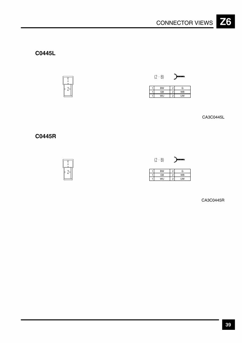
CONNECTOR VIEWS Z6
39
CA3C0445L
C0445L
1 BW
1 GB
1 WU
2 G
2 WB
2 UW
CA3C0445R
C0445R
1 BW
1 GB
1 WU
2 G
2 WB
2 UW
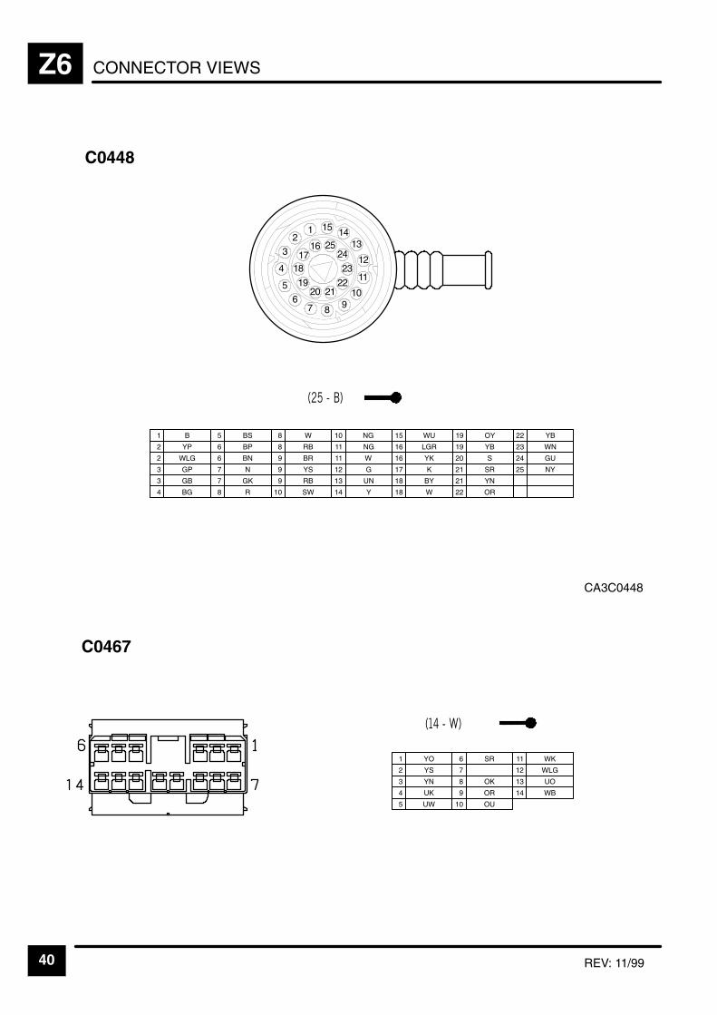
CONNECTOR VIEWSZ6
40 REV: 11/99
2
2311
12
13141 15
CA3C0448
25
10987
6
5
4
3 1617
18
1920 21
22
24
C0448
1 B
2 YP
2 WLG
5 BS
6 BP
6 BN
8 W
3 GP 7 N
8 RB
9 BR
9 YS
11 NG
12 G
13 UN3 GB 7 GK 9 RB
14 Y
15 WU
8 R 10 SW
16 LGR
16 YK
17 K
19 OY
19 YB
20 S
18 BY
21 SR
21 YN
18 W 22 OR
22 YB
4 BG
23 WN
24 GU
25 NY
11 W
10 NG
C0467
1 YO
2 YS
3 YN
6 SR
7
8 OK
10 OU
11 WK
4 UK 9 OR
12 WLG
13 UO
5 UW
14 WB
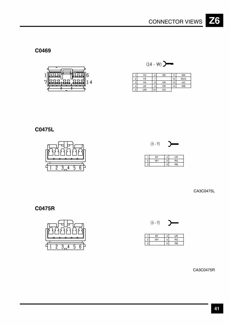
CONNECTOR VIEWS Z6
41
C0469
1 YO
2 YS
3 YN
6 SR
7
8 OK
10 OU
11 WK
4 UK 9 OR
12 WLG
13 UO
5 UW
14 WB
CA3C0475L
C0475L
1 BY
2 WY
3
4 UR
5 RG
6 RB
CA3C0475R
C0475R
1 BY
2 WY
3
4 UR
5 RG
6 RB
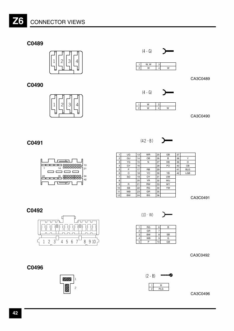
CONNECTOR VIEWSZ6
42
1
22
14
35
1321
34
42
CA3C0489
C0489
1 W, W
2 W
3
4 W
CA3C0490
C0490
1 W
2 W
3
4 W
1 UG
2 GU
3 YG
7 SO
8
9 R
13 WR
4 GY
10 SB
14 OB
15 N
16
19 OY
20 YR
21 RW
5 P
11 WB
17 RB
22 RG
23 GR
12 BW
18 YO
24 BG
25 GB
26 B
29
30 YB
31 UW
27 KB
32 WU
33 WY
28 PO
34 YW
35
6 O
36
37
38 Y
39 O
40 OB
41 BLG
42 LGB
CA3C0491
C0491
CA3C0496
C0496
1 B
2 PLG
CA3C0492
C0492
1 RG
2 GR
3 BW
4 WB
5 P 10 GB
6 B
7
8 SB
9 G
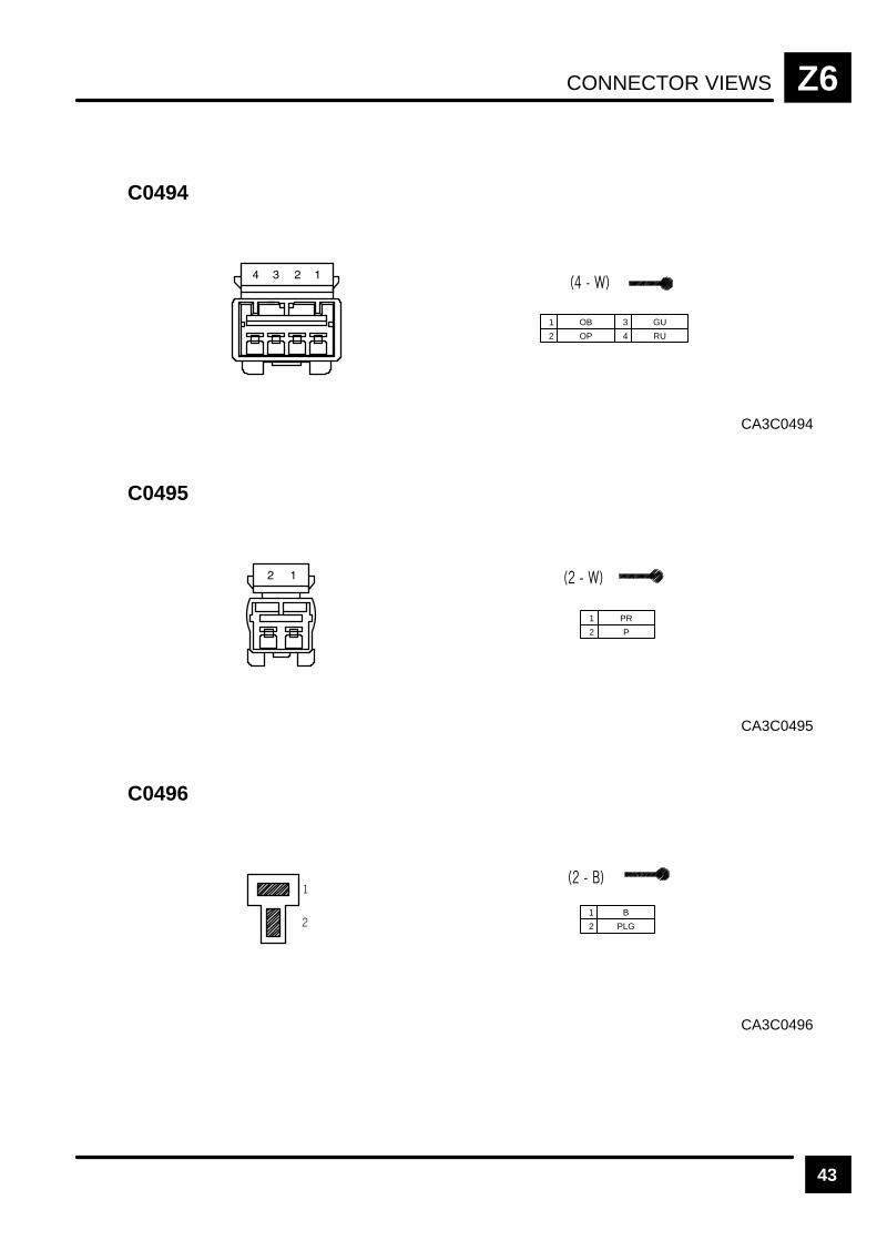
CONNECTOR VIEWS Z6
43
CA3C0494
C0494
1 OB
2 OP
3 GU
4 RU
CA3C0495
C0495
1 PR
2 P
CA3C0496
C0496
1 B
2 PLG

CONNECTOR VIEWSZ6
44
CA3C0499
C0499
1 Y
2 U
3 W
5 N
7 B
6 R
4 G
CA3C0501
C0501
1 SN
2 SB
3 B
6 SK
7 SR
8 S
10 SO
11 SU
4 SY 9 SW
12 LG
13 SP
5 SG
CA3C0502
C0502
1 N
2 U
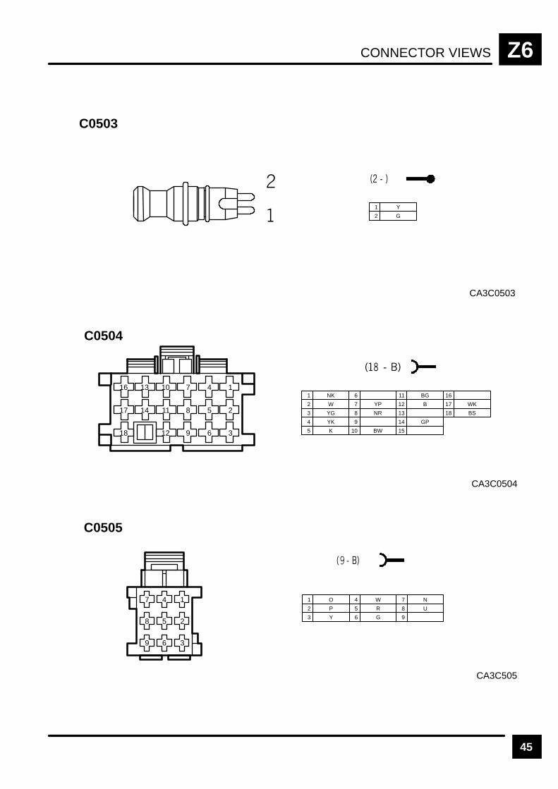
CONNECTOR VIEWS Z6
45
CA3C0503
C0503
1 Y
2 G
1 NK
2 W
3 YG
6
7 YP
8 NR
11 BG
4 YK 9
12 B
13
14 GP
16
17 WK
18 BS
5 K 10 BW 15
16 13 10 7 4 1
17 14 11 8 5 2
18 12 9 6 3
CA3C0504
C0504
CA3C505
C0505
1 O
2 P
3 Y
4 W
5 R
6 G
7 N
8 U
9
9 6 3
8 5 2
7 4 1

CONNECTOR VIEWSZ6
46
CA3C0506
C0506
1 SN
2 SK
3 B
5 SR
6
7 SG
9
4 SU 8 S
10 SP
11 LG
12 SW
13 SB
14 SO
15 SY
CA3C0507
C0507
1 NR
2 B
CA3C0513
C0513
1 RY
2 B

CONNECTOR VIEWS Z6
47
CA3C0514
C0514
1 RY
2 B
CA3C0516
C0516
1 O
2 P
CA3C0517
C0517
1 N
2 B
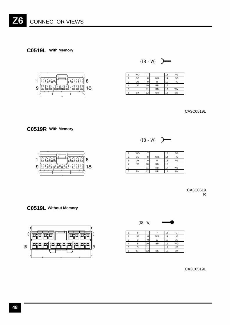
CONNECTOR VIEWSZ6
48
CA3C0519L
C0519L
1 WG
2 BG
3 UY
7
8 WB
12 UR
4 W
9 U
13 RG
14 RG
17 WY
18 BW
5
10 RB
15 RG
6 BY
11 RB
16
With Memory
CA3C0519R
C0519R
1 WG
2 BG
3 UY
7
8 WB
12 UR
4 W
9 U
13 RG
14 RG
17 WY
18 BW
5
10 RB
15 RG
6 BY
11 RB
16
With Memory
CA3C0519L
C0519L Without Memory
1 B
2 W
3 B
7 Y
8 WB
12 BS
4 B
9 W
13 G
14 UG
17 YB
18 BW
5 O
10 BP
15 BG
6 SR
11
16 WG
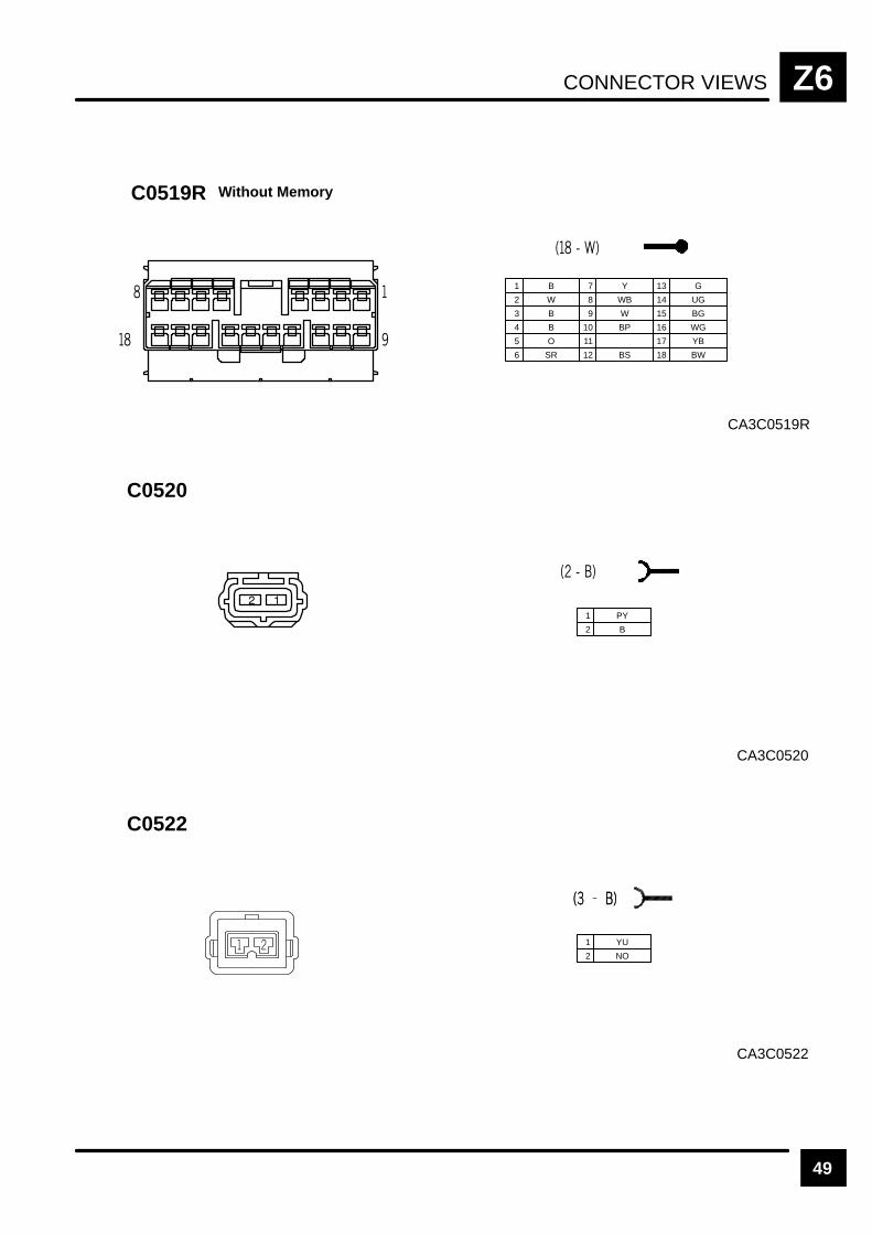
CONNECTOR VIEWS Z6
49
CA3C0519R
C0519R Without Memory
1 B
2 W
3 B
7 Y
8 WB
12 BS
4 B
9 W
13 G
14 UG
17 YB
18 BW
5 O
10 BP
15 BG
6 SR
11
16 WG
CA3C0520
C0520
1 PY
2 B
CA3C0522
C0522
1 YU
2 NO

CONNECTOR VIEWSZ6
50
CA3C0523
C0523
1 YW
2 NO
CA3C0524
C0524
1 YB
2 NO
CA3C0525
C0525
1 YN
2 NO

CONNECTOR VIEWS Z6
51
CA3C0526
C0526
1 YG
2 NO
CA3C0527
C0527
1 YS
2 NO
CA3C0528
C0528
1 YR
2 NO
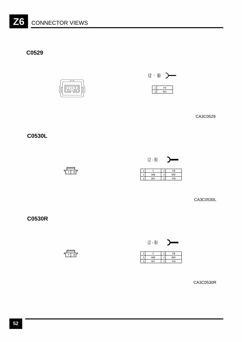
CONNECTOR VIEWSZ6
52
CA3C0529
C0529
1 YK
2 NO
CA3C0530L
C0530L
1 Y
1 WB
1 WY
2 YB
2 BW
2 YW
CA3C0530R
C0530R
1 Y
1 WB
1 WY
2 YB
2 BW
2 YW

CONNECTOR VIEWS Z6
53REV: 11/99
CA3C0540
C0540
2 1
(2–W)
1 N
2 W
CA3C0570
C0570
1 WO
2 BN
3 RB
4 NU
5 NU
6 WR
7 BY
8 NR
CA3C0571
C0571
1 G
2 BU
3 B
4 BN
5 LGR
6 BY
7 PLG
8 W
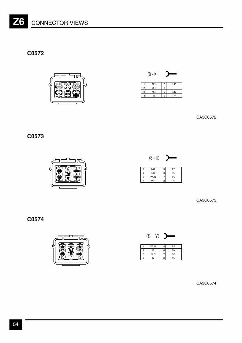
CONNECTOR VIEWSZ6
54
CA3C0572
C0572
1 NR
2 UR
3 NO
4 W
5 UP
6
7 NK
8 PY
CA3C0573
C0573
1 NG
2 NK
3 WLG
4 WP
5 PB
6 PN
7 PB
8 N
CA3C0574
C0574
1 WLG
2 B
3 PLG
4 N
5 PR
6 BN
7 PG
8 PN
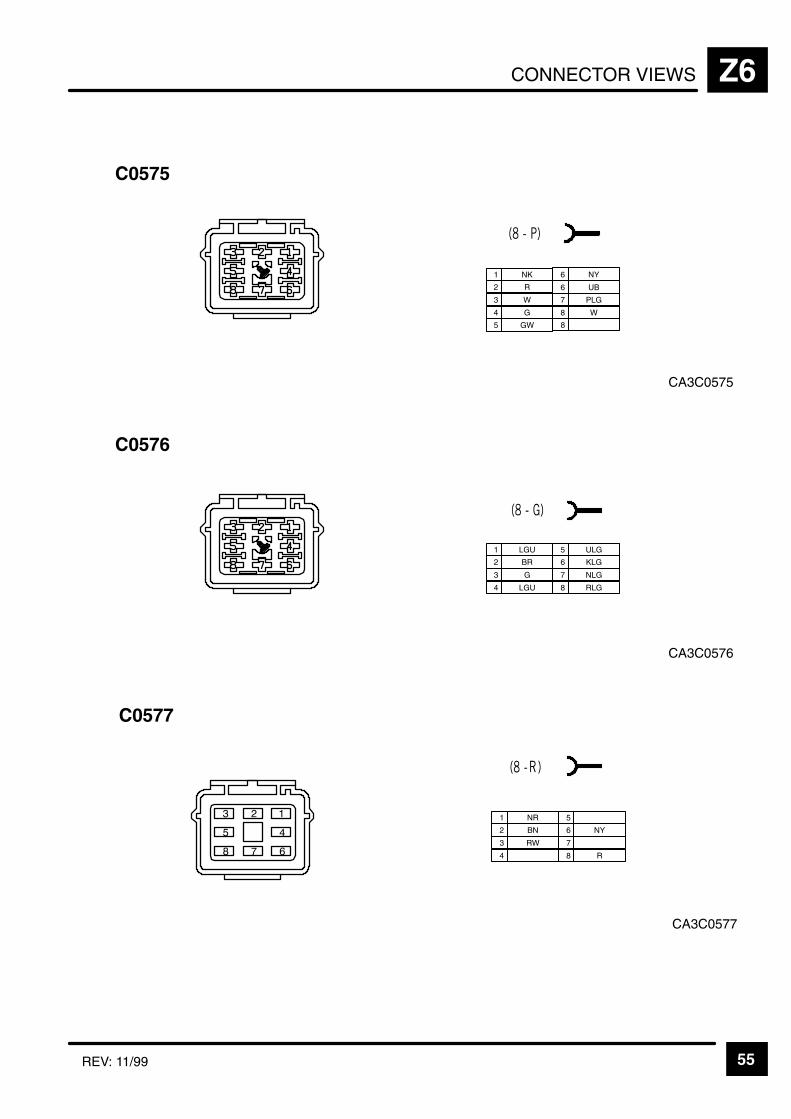
CONNECTOR VIEWS Z6
55REV: 11/99
CA3C0575
C0575
1 NK
2 R
3 W
4 G
5 GW
6 NY
7 PLG
8 W
6 UB
8
CA3C0576
C0576
1 LGU
2 BR
3 G
4 LGU
5 ULG
6 KLG
7 NLG
8 RLG
CA3C0577
C0577
1 NR
2 BN
3 RW
4
5
6 NY
7
8 R
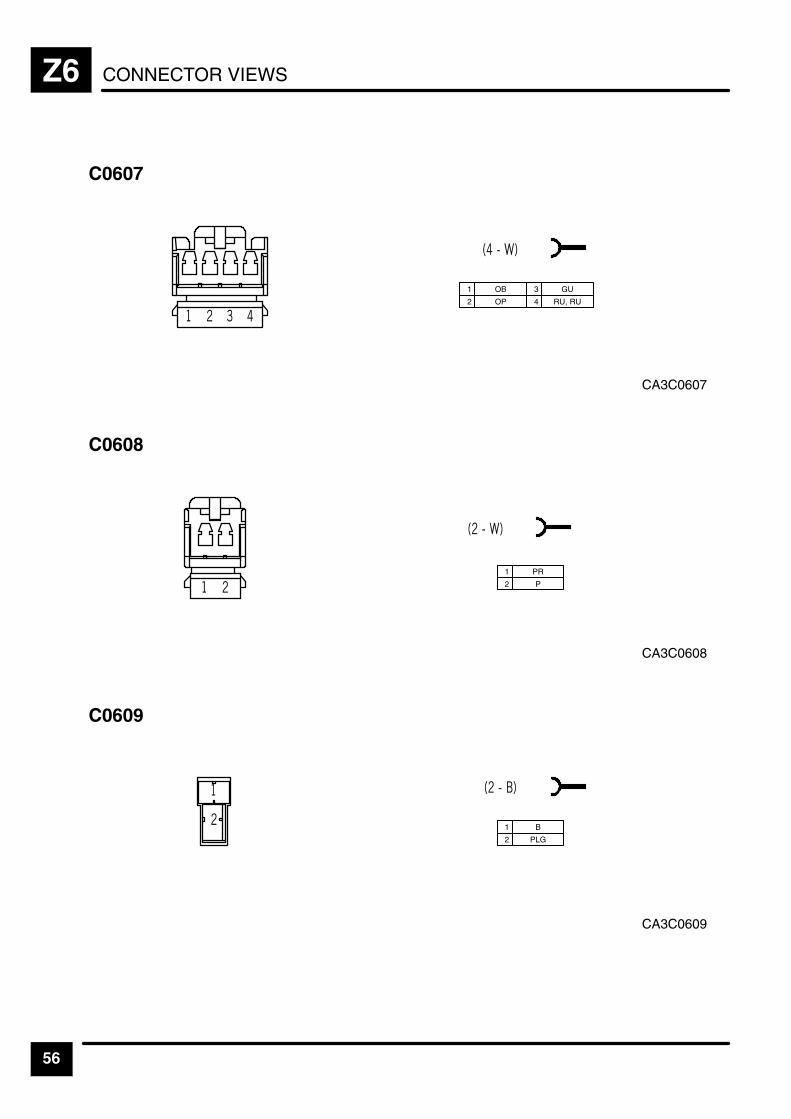
CONNECTOR VIEWSZ6
56
CA3C0607
C0607
1 OB
2 OP
3 GU
4 RU, RU
CA3C0608
C0608
1 PR
2 P
CA3C0609
C0609
1 B
2 PLG

CONNECTOR VIEWS Z6
57
CA3C0613
C0613
1 B
2 GU
CA3C0615
C0615
1 W
2 W
3
CA3C0616
C0616
1 W
2 W

CONNECTOR VIEWSZ6
58
CA3C0617
C0617
1 W
2 W
CA3C0620
C0620
1 YB
2 BP
CA3C0626
C0626
1 KB
2 B
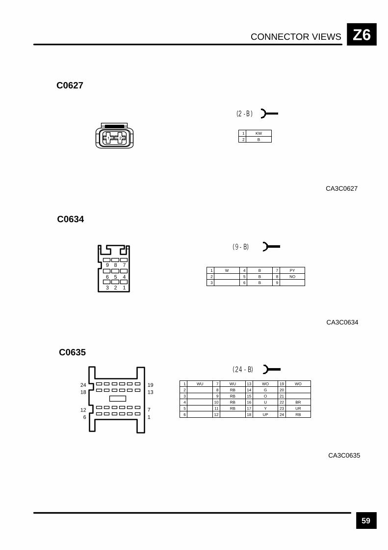
CONNECTOR VIEWS Z6
59
CA3C0627
C0627
1 KW
2 B
CA3C0634
C0634
3 2 1
6 5 4
9 8 71 W
2
3
4 B
5 B
6 B
7 PY
8 NO
9
CA3C0635
C0635
2418
126
1913
71
1 WU
2
3
7 WU
8 RB
9 RB
13 WO
4 10 RB
14 G
15 O
16 U
19 WO
20
21
5 11 RB 17 Y
22 BR
23 UR
6 12 18 UP 24 RB
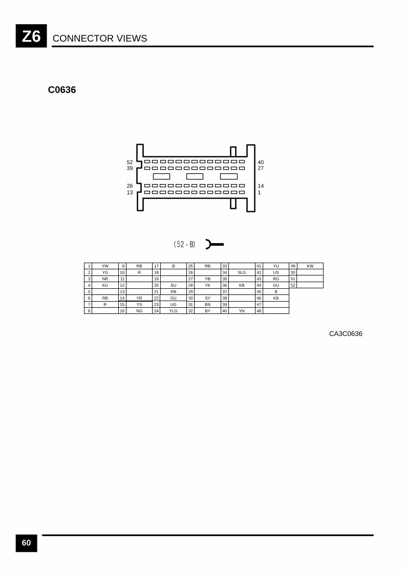
CONNECTOR VIEWSZ6
60
CA3C0636
C0636
1 YW
2 YG
3 NR
7 R
8
9 RB
13
4 KU
10 R
14 YR
15 YS
16 NG
19
20 SU
21 RB5
11
17 B
22 GU
23 UG
6 RB
12
18
24 YLG
25 RB
26
29
30 SY
31 BN
27 YB
32 BY
33
28 YK
34 SLG
35
36 KB
37
38
39
40 YN
41 YU
42 US
43 RG
44 GU
45 B
46 KB
47
48
49 KW
50
51
52
5239
2613
4027
141
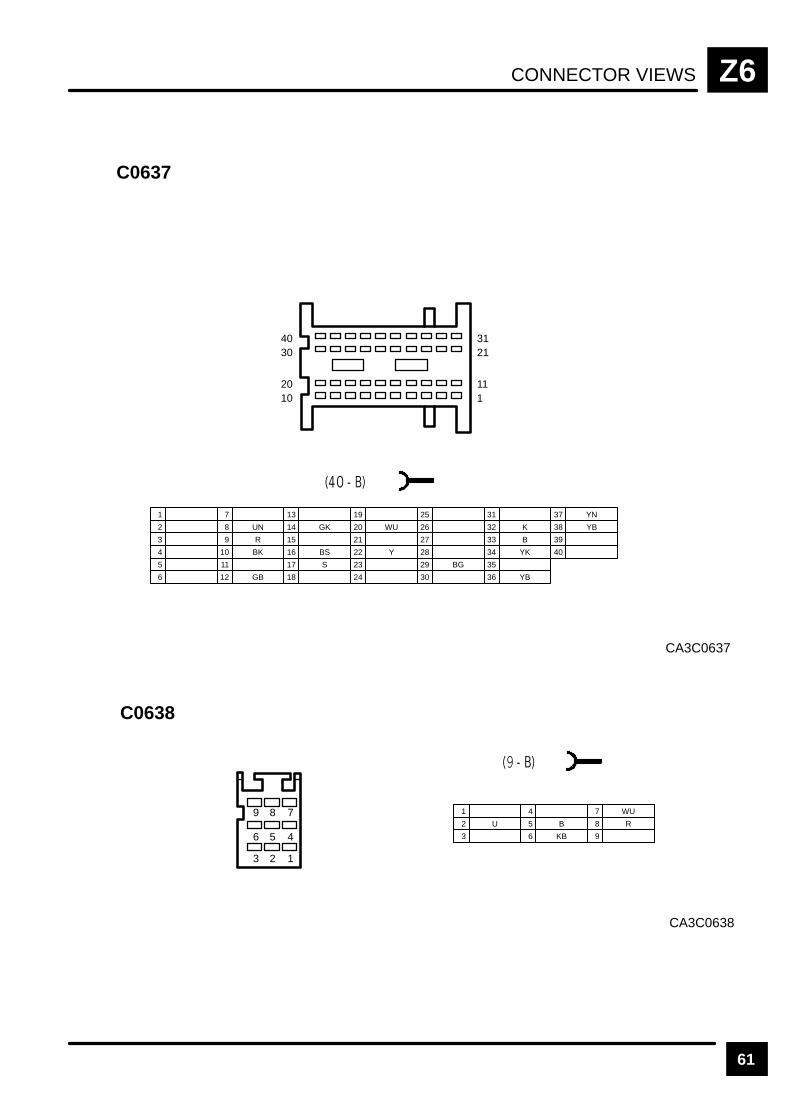
CONNECTOR VIEWS Z6
61
CA3C0637
C0637
4030
2010
3121
111
1
2
3
7
8 UN
9 R
13
4 10 BK
14 GK
15
16 BS
19
20 WU
21
5 11 17 S
22 Y
23
12 GB 18 24
25
26
29 BG
30
31
27
32 K
33 B
28 34 YK
35
6 36 YB
37 YN
38 YB
39
40
CA3C0638
C0638
1
2 U
3
4
5 B
6 KB
7 WU
8 R
9
3 2 1
6 5 4
9 8 7
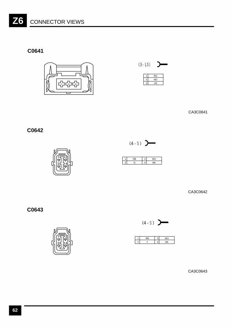
CONNECTOR VIEWSZ6
62
CA3C0641
C0641
1 RG
2 NO
3 US
CA3C0642
C0642
1 RB
2 G
3 WU
4 NK
CA3C0643
C0643
1 RB
2 Y
3 WU
4 NK

CONNECTOR VIEWS Z6
63
CA3C0644
C0644
1 RB
2 O
3 WO
4 WK
CA3C0645
C0645
1 RB
2 U
3 WO
4 NK
CA3C0646
C0646
3
2
11 BK
2
3 NK
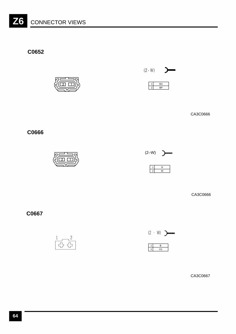
CONNECTOR VIEWSZ6
64
C0652
CA3C0666
1 BG
2 BP
CA3C0666
C0666
(2–W)
1 N
2 W
CA3C0667
C0667
1 B
2 YG
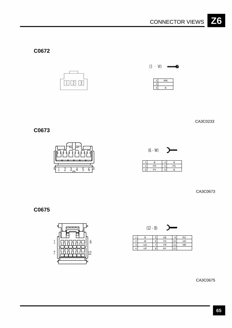
CONNECTOR VIEWS Z6
65
CA3C0233
C0672
1 NW
2
3 B
CA3C0673
C0673
1 B
2 PR
3 PY
4 B
5 PG
6 B
CA3C0675
C0675
1 B
2 W
3 UG
5 UB
6 YG
7 YR
9 RU
10 UO
11 NR
4 UP 8 NY 12
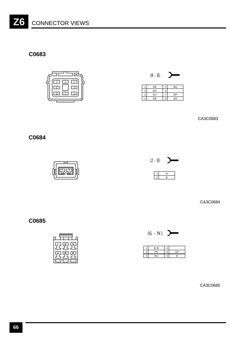
CONNECTOR VIEWSZ6
66
CA3C0683
C0683
1 KB
2 KN
3 KU
4 KR
5 BG
6
7 RP
8 RS
CA3C0684
C0684
1 N
2 B
CA3C0685
C0685
1 B, B
2 PG
3 RU
4
5 GP
6 B

CONNECTOR VIEWS Z6
67
CA3C0686
C0686
1 B
2 BP
CA3C0688L
C0688L
1 YB
1 BG
1 YG
2 Y
2 GB
2 GY
CA3C0688R
C0688R
1 YB
1 BG
1 YG
2 Y
2 GB
2 GY
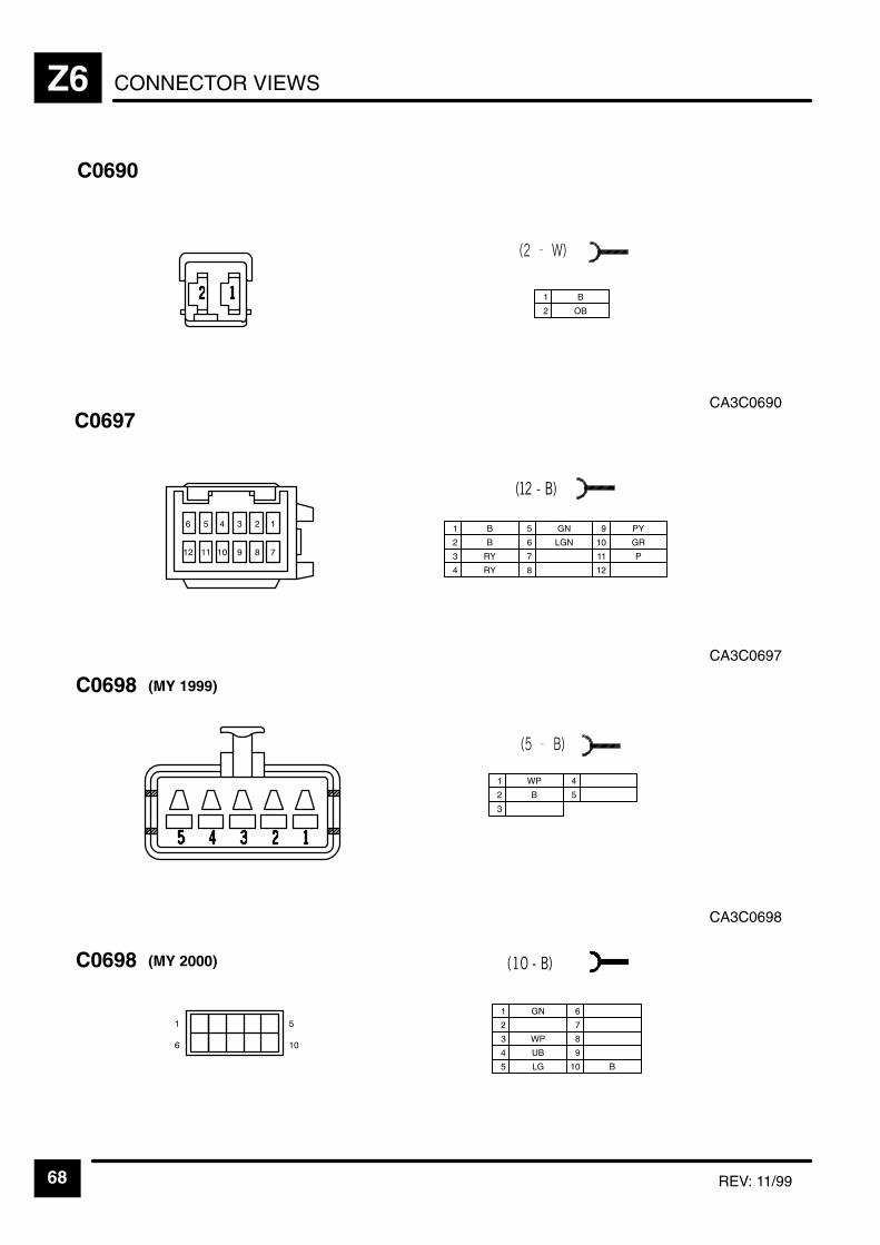
CONNECTOR VIEWSZ6
68 REV: 11/99
CA3C0690
C0690
1 B
2 OB
CA3C0697
C0697
1 B
2 B
3 RY
5 GN
6 LGN
7
9 PY
10 GR
11 P
4 RY 8 12
CA3C0698
C0698
1 WP
2 B
3
4
5
(MY 1999)
C0698 (MY 2000)
1 GN
2
3 WP
4 UB
5 LG 10 B
6
7
8
9
&
"
& "

CONNECTOR VIEWS Z6
69REV: 11/99
CA3C0726L
C0726L
1 RG
1 GB
3 UG
2 G
2 GR
2 GU
CA3C0726R
C0726R
1 RG
1 GB
1 UG
2 G
2 GR
2 GU
CA3C0731
C0731
(4–N)
1 PR
2 W
3 PY
4 B
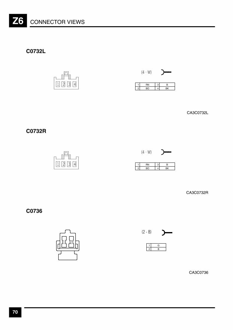
CONNECTOR VIEWSZ6
70
CA3C0732L
C0732L
1 RN
2 BO
3 B
4 BK
CA3C0732R
C0732R
1 RN
2 BO
3 B
4 BK
CA3C0736
C0736
1 G
2 B

CONNECTOR VIEWS Z6
71
CA3C0737
C0737
1 G
2 B
CA3C0745
C0745
1
2 BS
3 UB
6 OLG
7
8
11 SO
4 UP 9 OP
12 OG
13 K
14 Y
16
17
18
5 UG 10 OW 15 SCR
CA3C0746
C0746
1 KB
2 KN
3 KU
6 GB
7 B
8 U
10 SCR
11 RS
4 KR 9 W
12 RP
13 GN
5 BG
14 N
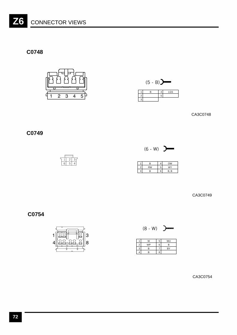
CONNECTOR VIEWSZ6
72
CA3C0748
C0748
1 B
2
3
4 LGS
5
CA3C0749
C0749
1 B
2 RW
3 B
4 OW
5 WY
6 B, B
CA3C0754
C0754
1 W
2 WP
3 B
5 WU
6 B
7 BY
4 B 8
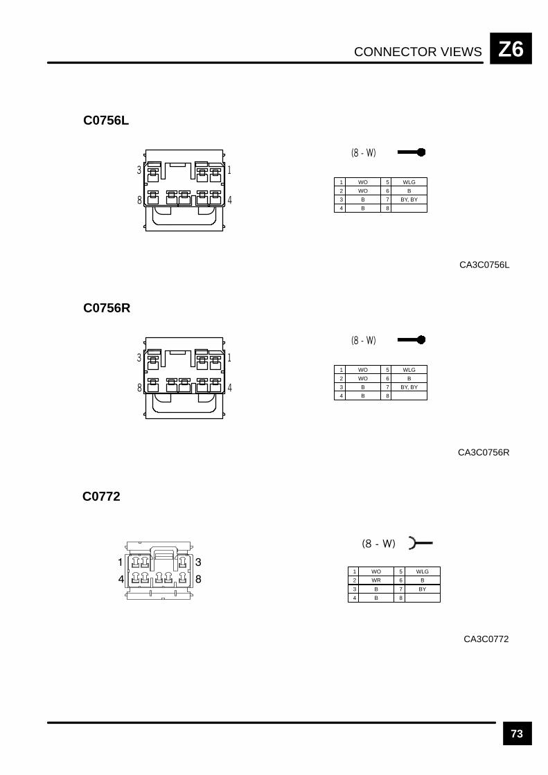
CONNECTOR VIEWS Z6
73
CA3C0756L
C0756L
1 WO
2 WO
3 B
5 WLG
6 B
7 BY, BY
4 B 8
CA3C0756R
C0756R
1 WO
2 WO
3 B
5 WLG
6 B
7 BY, BY
4 B 8
CA3C0772
C0772
1 WO
2 WR
3 B
4 B
5 WLG
6 B
7 BY
8
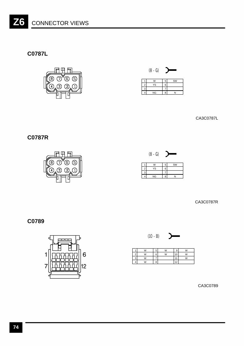
CONNECTOR VIEWSZ6
74
CA3C0787L
C0787L
1 W
2 YS
3
4 NG
5 SW
6
7
8 N
CA3C0787R
C0787R
1 W
2 YS
3
4 NG
5 SW
6
7
8 N
CA3C0789
C0789
1 W
2 W
3 W
5 W
6 W
7
9 W
10 W
11 W
4 W 8 12
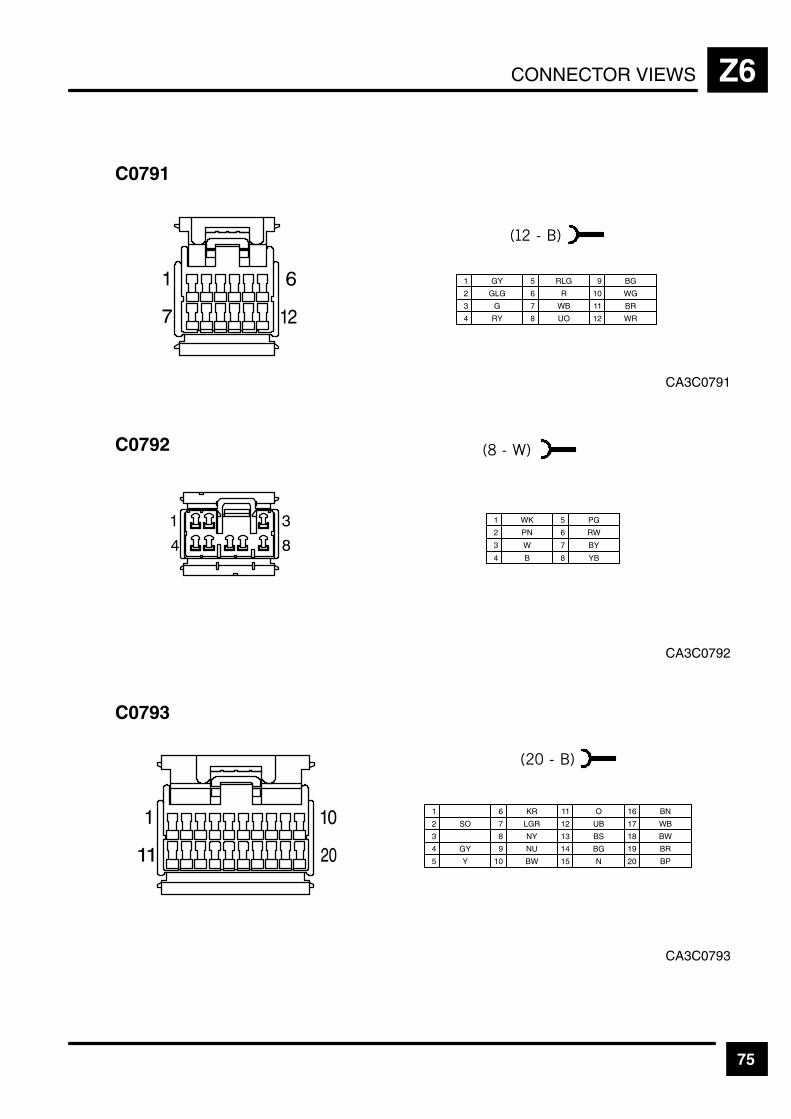
CONNECTOR VIEWS Z6
75
CA3C0791
C0791
1 GY
2 GLG
3 G
5 RLG
6 R
7 WB
9 BG
10 WG
11 BR
4 RY 8 UO 12 WR
CA3C0792
C0792
1 WK
2 PN
3 W
4 B
5 PG
6 RW
7 BY
8 YB
CA3C0793
C0793
1
2 SO
3
6 KR
7 LGR
8 NY
11 O
4 GY 9 NU
12 UB
13 BS
14 BG
16 BN
17 WB
18 BW
5 Y 10 BW 15 N
19 BR
20 BP
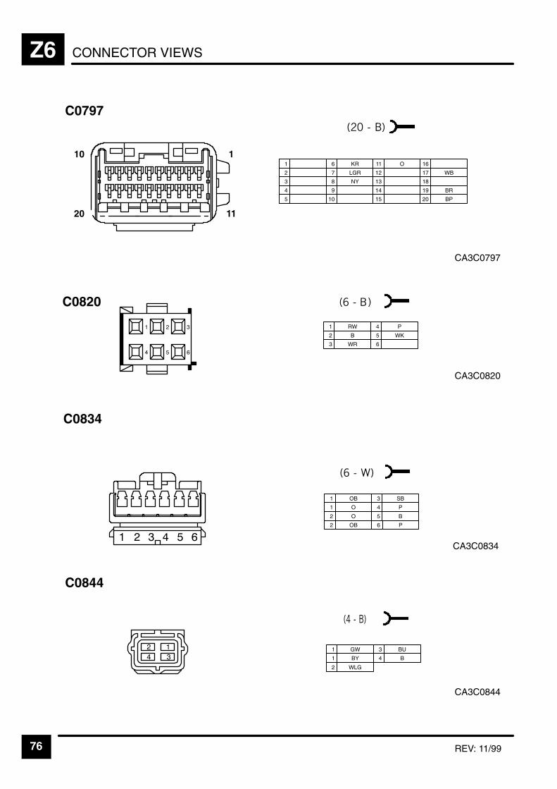
CONNECTOR VIEWSZ6
76 REV: 11/99
CA3C0797
C0797
1
2
3
6 KR
7 LGR
8 NY
11 O
4 9
12
13
14
16
17 WB
18
5 10 15
19 BR
20 BP
1 RW
2 B
3 WR
4 P
5 WK
6
CA3C0820
C0820
CA3C0834
C0834
1 OB
1 O
2 O
3 SB
4 P
5 B
2 OB 6 P
CA3C0844
C0844
1 GW
1 BY
3 BU
4 B
2 WLG
10
20
1
11
"
&

CONNECTOR VIEWS Z6
77
CA3C0845
C0845
1 YB
2 BN
CA3C0853
C0853
1 NU
2 LGU
3
4 B
CA3C0854
C0854
1 NU
2 LGU
3 LG
4 B
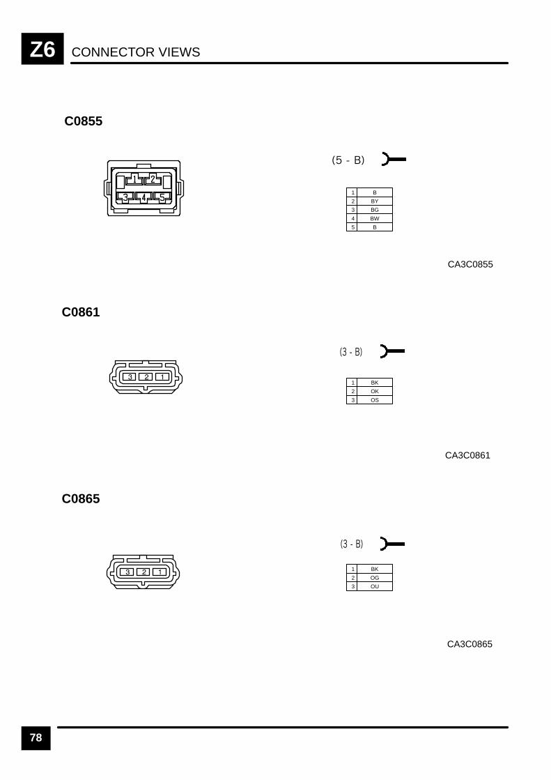
CONNECTOR VIEWSZ6
78
CA3C0855
C0855
1 B
2 BY
3 BG
4 BW
5 B
CA3C0861
C0861
1 BK
2 OK
3 OS
CA3C0865
C0865
1 BK
2 OG
3 OU
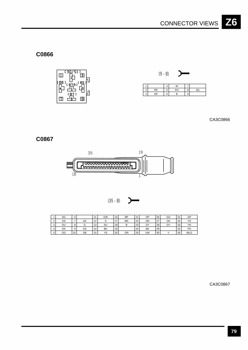
CONNECTOR VIEWS Z6
79
C0866
CA3C0866
1
2 PR
3 SR
4 W
5 PO
6 B
7
8 SG
9
C0867
CA3C0867
1 SG
2 OS
3 OU
7 UK
8 G
9 GS
13 SU
4 OK
10 GB
14 BK
15 YS
16 BP
19
20 OR
21 OP
5 OG
11 GW
17 WK 22 ON
23 OY
6
12 S
18 B
24 BK
25 UW
26 GO
29
30 Y
31 GP
27 GK 32 YO
33 YN28 GY
34 PO
35 WLG
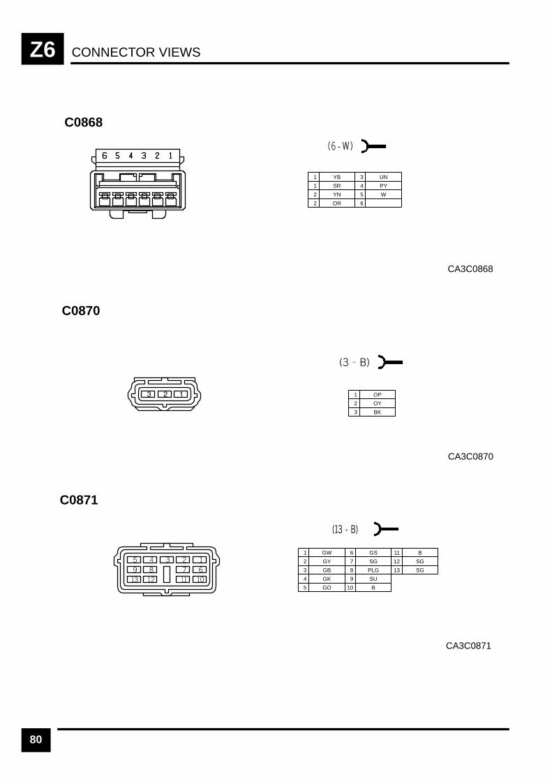
CONNECTOR VIEWSZ6
80
CA3C0868
C0868
1 YB
1 SR
2 YN
2 OR
3 UN
4 PY
5 W
6
CA3C0870
C0870
1 OP
2 OY
3 BK
CA3C0871
C0871
1 GW
2 GY
3 GB
6 GS
7 SG
8 PLG
10 B
11 B
4 GK 9 SU
12 SG
13 SG
5 GO

CONNECTOR VIEWS Z6
81
CA3C0873
C0873
1
2 BP
3 B
4 PLG
CA3C0874
C0874
1 LG
2 B
CA3C0875
C0875
1 OR
2 ON
3 BK
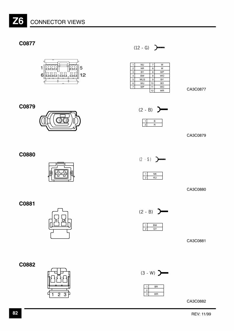
CONNECTOR VIEWSZ6
82 REV: 11/99
CA3C0877
C0877
1 NU
2 NR
3 BY
6 WU
7 WP
7 W
8 WP
9 BY
4 BW
8 W
10 BO
11 WO
5 WLG
12 WR
CA3C0881
C0881
1 BW
2 GY
CA3C0882
C0882
1 BR
2
3 WR
1 B
2 R
C0879
CA3C0879
CA3C0880
1 NK
2 KU
C0880
8 WO

CONNECTOR VIEWS Z6
83
CA3C0883
C0883
1 BG
2
3 WG
CA3C00C884
C0884
1 UO
2 WB
CA3C00C890
C0890
1 BW
2 SO

CONNECTOR VIEWSZ6
84
CA3C0891
C0891
1 PR
2 P
CA3C0893
C0893
1 UW
2 RW
3 W
4 UK
5 PB
6 YN
7 B
8 YO
CA3C0894
C0894
1 B
2 RW
3 YS
4 W
5 YS, YS
6 B, B

CONNECTOR VIEWS Z6
85
CA3C0894P
C0895P
1
2 RY
3
4 SY
5 YS
6 YR
7
8 OW
9
CA3C0895D
C0895D
1
2 B
3 8 OW
4 OY
5 YS
6 YR
7
9
CA2C0903
C0903
1 SR
1 YB
2 OY
2 YN
3 UN
4 PY
5 W
6

CONNECTOR VIEWSZ6
86 REV: 11/99
CA2C0921
C0921
&
"
1 O
2 B
2 P
3
4 OB
5 Y
6
CA3C0922
C0922
1
2
3
5
6
7
9
10 KB
11
4 8 12
C0923
1 O
2 KR
3 LGR
5
6
7
9 WB
10
11 BP
4 NY 8 12 BR
CA2C0923
CA2C0925
C0925
1 R
2 B
3 RW

CONNECTOR VIEWS Z6
87
CA3C0941
C0941
1 W
2 B
3 O
4
5 G
10 P
6 R
7 S
8 N
9
&
"
CA3C0948
C0948
1 WD
2 WP
CA3C0949
C0949
1 RO
2 RP

CONNECTOR VIEWSZ6
88 REV: 11/99
CA3C0950
C0950
1 S
2 SG
3 SK
1 B
2 RS
3 SR
5 US
6 NY
7 WK
9
10
11
4 SU 8 P 12
71
126
CA3C0959
C0959
CA3C0951
C0951
1
2 UG
3 UK
C0974L
CA3C0974L
1 BP
2 BS
3 WLG
4
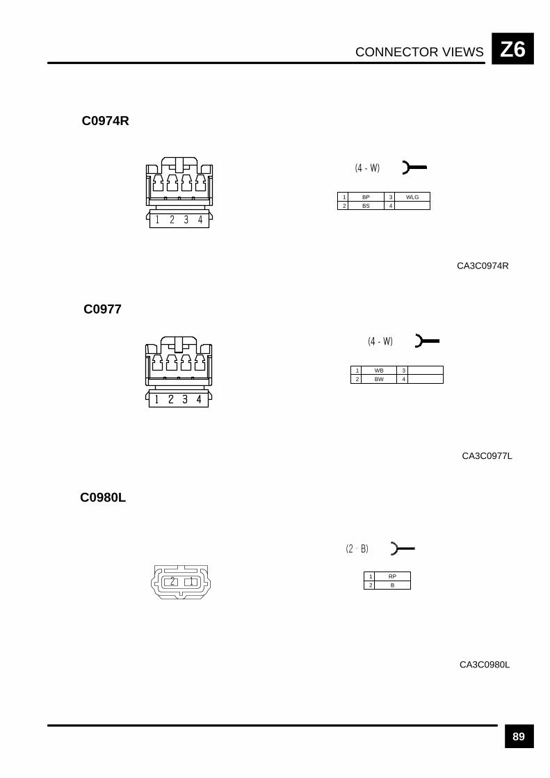
CONNECTOR VIEWS Z6
89
C0974R
CA3C0974R
1 BP
2 BS
3 WLG
4
CA3C0977L
C0977
1 WB
2 BW
3
4
CA3C0980L
C0980L
1 RP
2 B

CONNECTOR VIEWSZ6
90
CA3C0980R
C0980R
1 RP
2 B
CA3C0988
C0988
1
2 BS
3 UB
6 OLG
7
8
11 SO
4 UP 9 OP
12 OG
13 K
14 Y
16
17
18
5 UG 10 OW 15 B
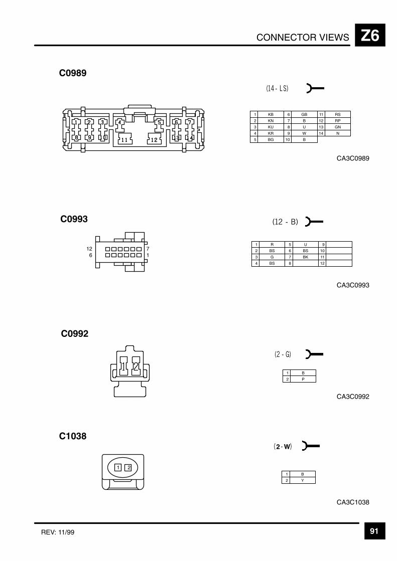
CONNECTOR VIEWS Z6
91REV: 11/99
CA3C0989
C0989
1 KB
2 KN
3 KU
6 GB
7 B
8 U
10 B
11 RS
4 KR 9 W
12 RP
13 GN
5 BG
14 N
1 R
2 BS
3 G
5 U
6 BS
7 BK
9
10
11
4 BS 8 12
71
126
C0993
CA3C0993
C0992
1 B
2 P
CA3C1038
C1038
2 W
1 B
2 Y
CA3C0992
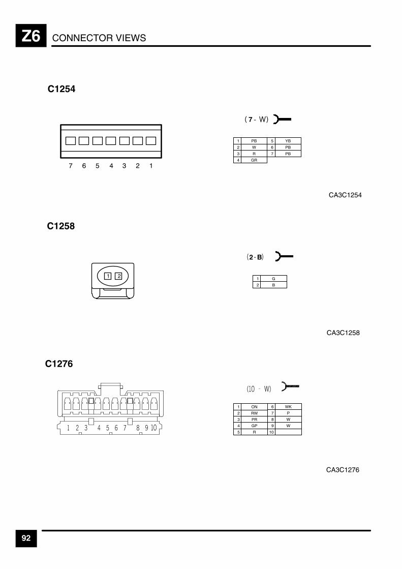
CONNECTOR VIEWSZ6
92
CA3C1254
C1254
& "
7
1 PB
2 W
3 R
5 YB
7 PB
6 PB
4 GR
CA3C1258
C1258
2 B
1 G
2 B
CA3C1276
C1276
1 ON
2 RW
3 PR
4 GP
5 R 10
6 WK
7 P
8 W
9 W

CONNECTOR VIEWS Z6
93
CA3C1277
C1277
1 R
2 OW
3 LGW
4 PW
5 O
6 LG
7 RW
8 P
CA3C1278
C1278
1 LGB
2 GW
3 U
6 WR
7 GR
8 US
11 OP
4 LGO 9 OR
12 UW
13 OB
14 RY
16 WG
17 PB
18 LGS
5 RLG 10 YR 15 ULG
19
20
CA3C1279
C1279
1 RN
2
3 NW
6 BR
7 GLG
8 KR
11 WB
4 YG 9 NY
12
13 PG
14 WY
16
17 LGR
18 OW
5 10 Y 15 BP
19
20 YR
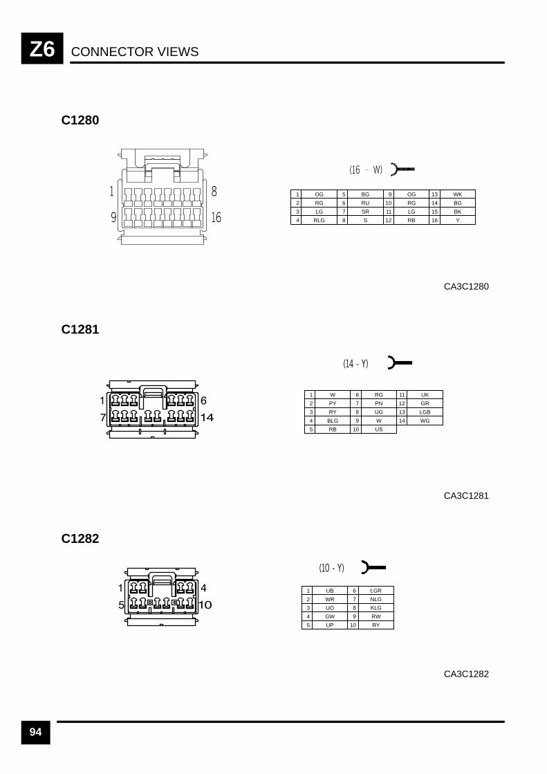
CONNECTOR VIEWSZ6
94
CA3C1280
C1280
1 OG
2 RG
3 LG
5 BG
6 RU
7 SR
9 OG
4 RLG 8 S
10 RG
11 LG
12 RB
13 WK
14 BG
15 BK
16 Y
CA3C1281
C1281
1 W
2 PY
3 RY
6 RG
7 PN
8 UG
10 US
11 UK
4 BLG 9 W
12 GR
13 LGB
5 RB
14 WG
CA3C1282
C1282
1 UB
2 WR
3 UO
4 GW
5 UP 10 RY
6 LGR
7 NLG
8 KLG
9 RW

CONNECTOR VIEWS Z6
95
CA3C1283
C1283
1 RY
2 LGN
3 RY, RY
6 OK
7 OB
8 O
11 PR
4 GW 9 GN
12 GP, GP
13 GU
14 GR
16 RU
17 P
18 K
5 WO 10 RW, RW 15 GY
CA3C1284
C1284
1 WP
2 PB
3 RB
5 SO
6 RP
7 OB
9 WR
10 S
11 RN
4 P 8 YR 12 PU
CA3C1285
C1285
1 OP
2 BP
3 PY
6 OR
7 Y
8 BO
11 YG
4 RY 9 R
12 PO
13 PW
14 YP
16 YU
17 BK
18
5 BG 10 OG 15 YB
19 LG
20 NU
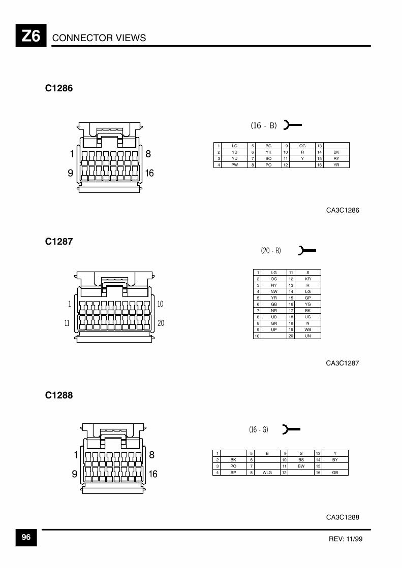
CONNECTOR VIEWSZ6
96 REV: 11/99
CA3C1286
C1286
1 LG
2 YB
3 YU
5 BG
6 YK
7 BO
9 OG
4 PW 8 PO
10 R
11 Y
12
13
14 BK
15 RY
16 YR
CA3C1287
C1287
1 LG
2 OG
3 NY
6 GB
7 NR
8 UB
11 S
4 NW
8 GN
12 KR
13 R
14 LG
16 YG
17 BK
18 UG
5 YR
9 UP
15 GP
18 N
19 WB
20 UN10
CA3C1288
C1288
1
2 BK
3 PO
5 B
6
7
9 S
4 BP 8 WLG
10 BS
11 BW
12
13 Y
14 BY
15
16 GB
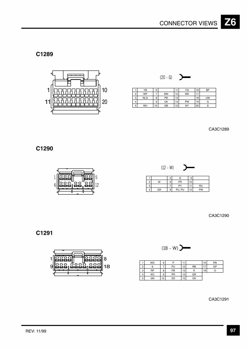
CONNECTOR VIEWS Z6
97REV: 11/99
CA3C1289
C1289
1 YB
2 WP
3 NLG
6
7 WN
8 PB
11 YG
4 9 UK
12 WK
13
14 PW
16 BP
17
18 UW
5 WU 10 GB 15 NY
19 G
20 S
CA3C1290
C1290
1
2 W
3
5 G
6 PR
7 PY
9
10
11 RU
4 GR 8 PU, PU 12 PW
CA3C1291
C1291
1 WO
2 S
3 RP
6 P
7 PU
8 PB
11
4 KO 9 PR
12 RB
13 K
14 GR
16 RN
17 GP
18 O
5 GN 10 SO 15 OK
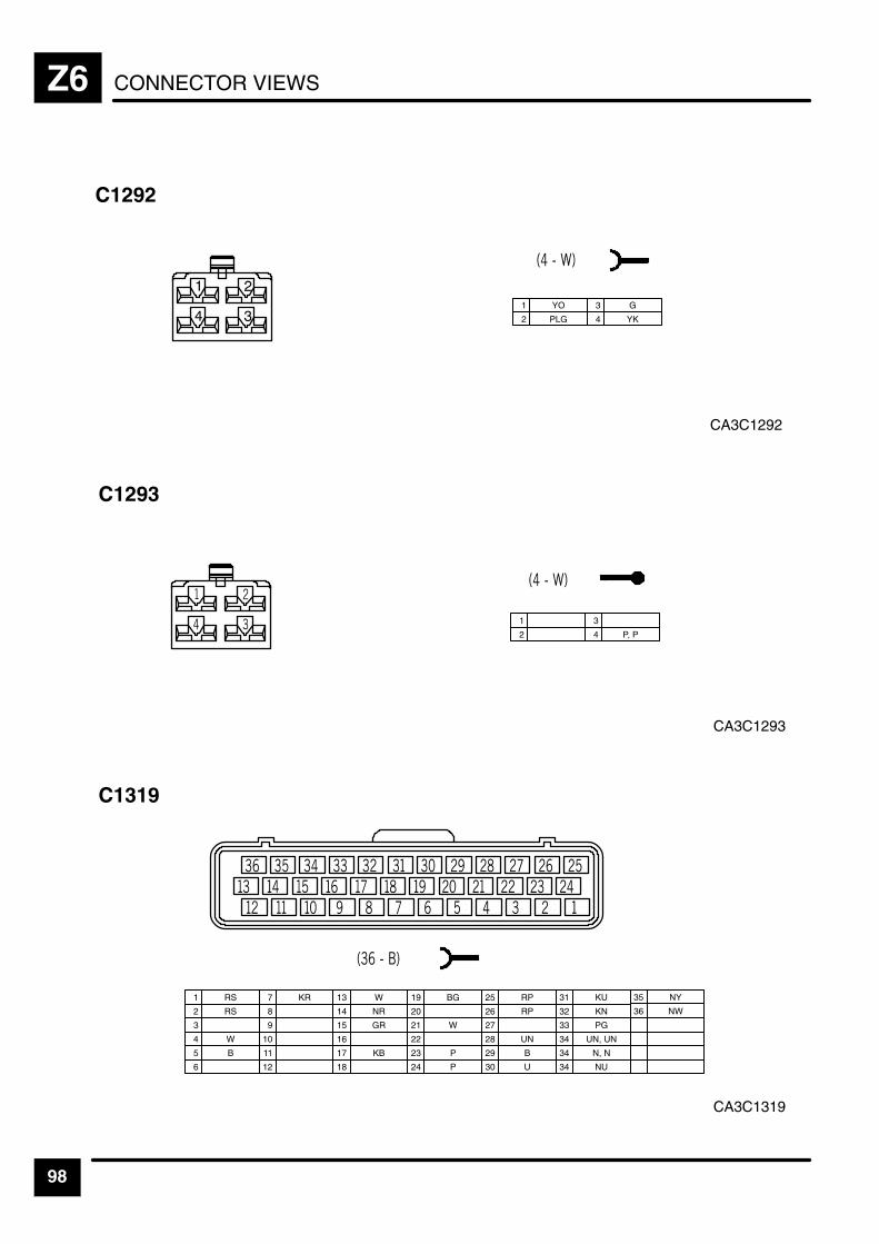
CONNECTOR VIEWSZ6
98
CA3C1292
C1292
1 YO
2 PLG
3 G
4 YK
CA3C1293
C1293
1
2
3
4 P, P
CA3C1319
C1319
1 RS
2 RS
3
7 KR
8
9
13 W
4 W 10
14 NR
15 GR
16
19 BG
20
21 W
5 B 11 17 KB
22
23 P
12 18 24 P
25 RP
26 RP
29 B
30 U
31 KU
27
32 KN
33 PG
28 UN 34 UN, UN
34 N, N
6 34 NU
35 NY
36 NW
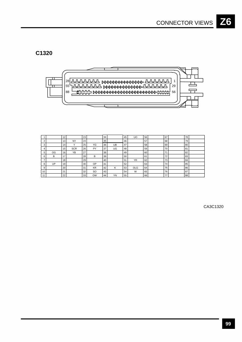
CONNECTOR VIEWS Z6
99
CA3C1320
C1320
1
2
3
7
8 UP
9
13 NY
4
10
14 Y
15 SCR
16 YB
19
20
21
5 OG
11
17
22
23
6 B
12
18
24
25 YG
26 PY
29
30 OP
31 KR
27
32 SO
33 OW
28 B
34
35
36 UB
37 UG
38
39
40
41
42 K
43
44 YN
45 UO
46
47
48
49
50
51 YR
52
53 OLG
54 W
55
28
55
88
1
29
56
56
57
58
59
60
61
62
63
64
65
66
67
68
69
70
71
72
73
74
75
76
77
78
79
80
81
82
83
84
85
86
87
88
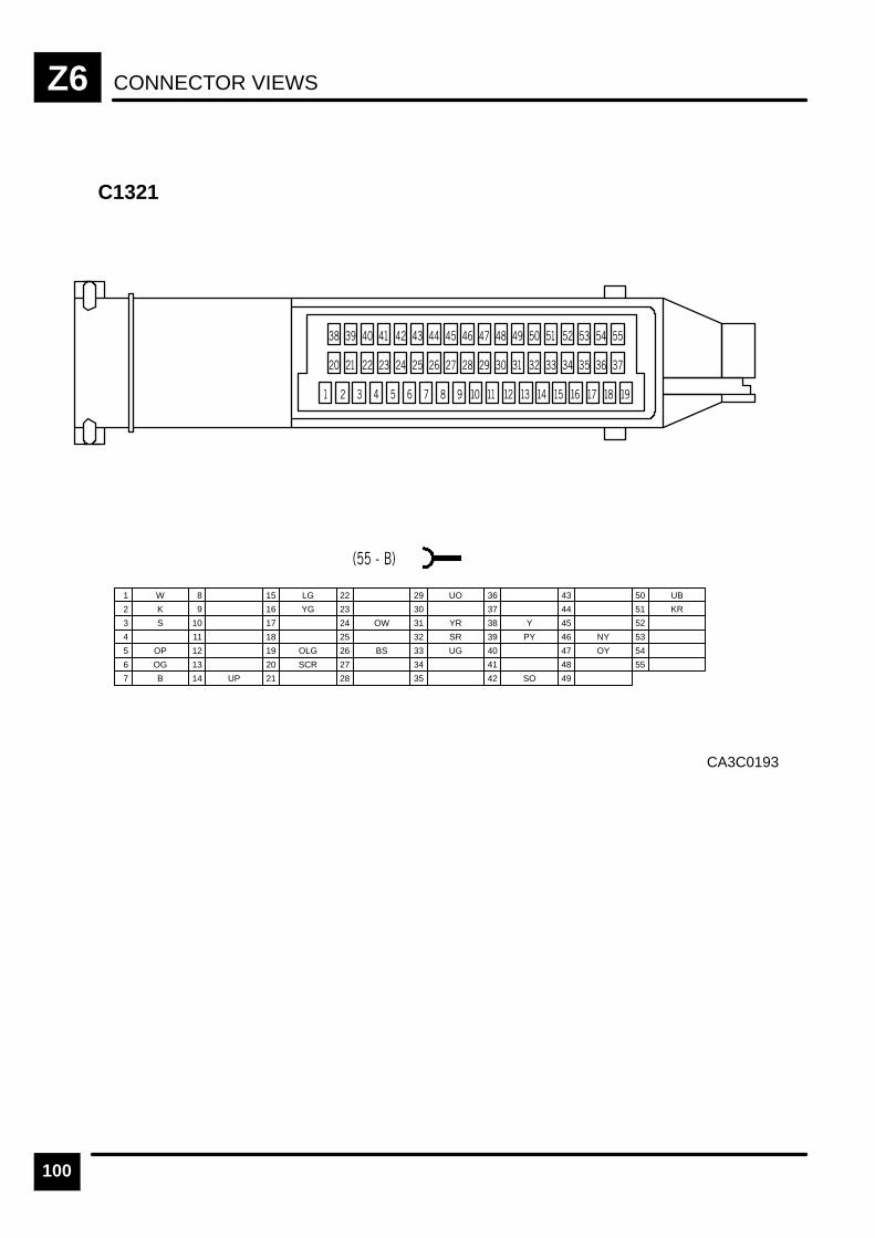
CONNECTOR VIEWSZ6
100
CA3C0193
C1321
1 W
2 K
3 S
7 B
8
9
13
4
10
14 UP
15 LG
16 YG
19 OLG
20 SCR
21
5 OP
11
17
22
23
6 OG
12
18
24 OW
25
26 BS
29 UO
30
31 YR
27
32 SR
33 UG
28
34
35
36
37
38 Y
39 PY
40
41
42 SO
43
44
45
46 NY
47 OY
48
49
50 UB
51 KR
52
53
54
55
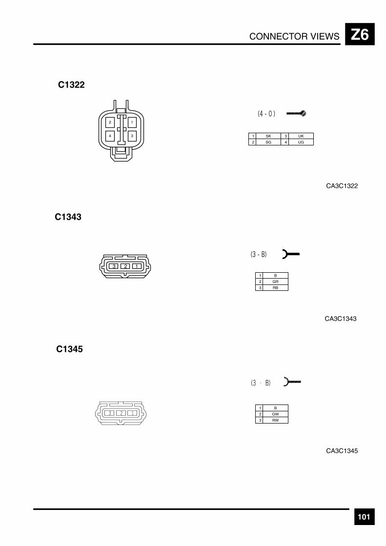
CONNECTOR VIEWS Z6
101
C1322
CA3C1322
1 SK
2 SG
3 UK
4 UG
CA3C1343
C1343
1 B
2 GR
3 RB
CA3C1345
C1345
1 B
2 GW
3 RW
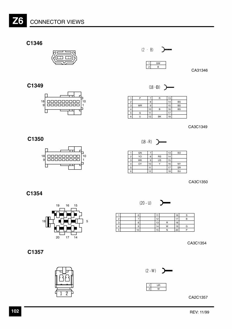
CONNECTOR VIEWSZ6
102 REV: 11/99
CA31346
C1346
1 GW
2 B
CA3C1350
C1350
101
189
1 GN
2 YO
3 WK
7
8 RS
12
4 OY
9 US
13 SO
14
17 SR
18 SU
5
10 Y
15
6
11
16 NY
1
2
3
6
7
8
11
4 9
12
13 R
14 W
16 S
17 B
18
5 10 15 N
19 G
20 P
CA3C1354
C1354
"
"
&
CA2C1357
C1357
1 UR
2 W
CA3C1349
C1349
101
189
1 P
2
3 WR
7 R
8
12 BK
4
9
13
14 BS
17
18
5 G
10 B
15 BS
6 U
11
16 BS

CONNECTOR VIEWS Z6
103
CA3C1358
C1358
1 B
2 GN
3 KO
4 WO
CA3C1359
C1359
1 U
2 G
3 R
4
CA3C1360
C1360
1 G
1 GU
2 GB
2 UG
3 PW
4 BO
5 BK
6 BG
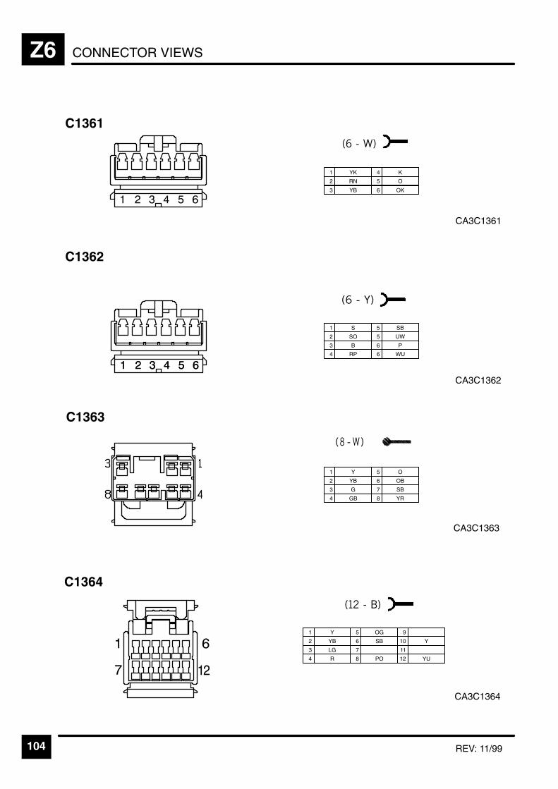
CONNECTOR VIEWSZ6
104 REV: 11/99
CA3C1361
C1361
1 YK
2 RN
3 YB
4 K
5 O
6 OK
CA3C1362
C1362
1 S
2 SO
3 B
4 RP
5 SB
5 UW
6 P
6 WU
CA3C1363
C1363
1 Y
2 YB
3 G
5 O
6 OB
7 SB
4 GB 8 YR
CA3C1364
C1364
1 Y
2 YB
3 LG
5 OG
6 SB
7
9
10 Y
11
4 R 8 PO 12 YU
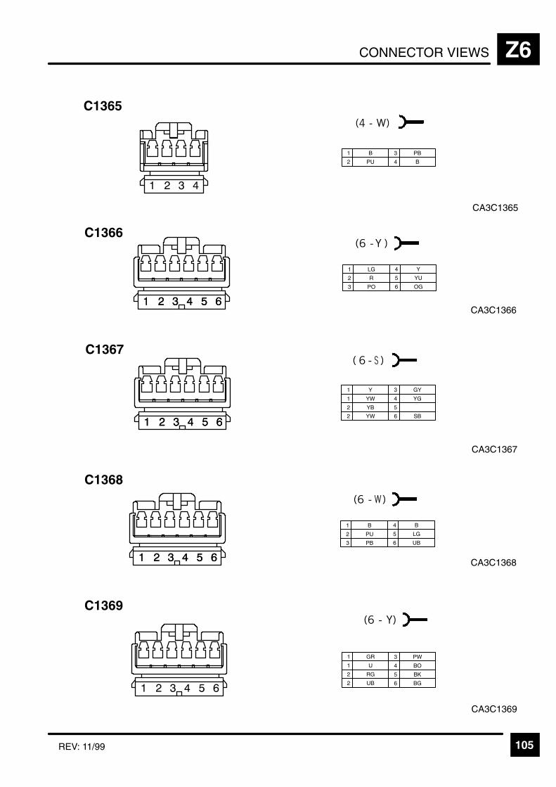
CONNECTOR VIEWS Z6
105REV: 11/99
CA3C1365
C1365
1 B
2 PU
3 PB
4 B
CA3C1368
C1368
1 B
2 PU
3 PB
4 B
5 LG
6 UB
CA3C1369
C1369
1 GR
1 U
2 RG
2 UB
3 PW
4 BO
5 BK
6 BG
CA3C1366
C1366
1 LG
2 R
3 PO
4 Y
5 YU
6 OG
CA3C1367
C1367
1 Y
1 YW
2 YB
3 GY
4 YG
5
2 YW 6 SB
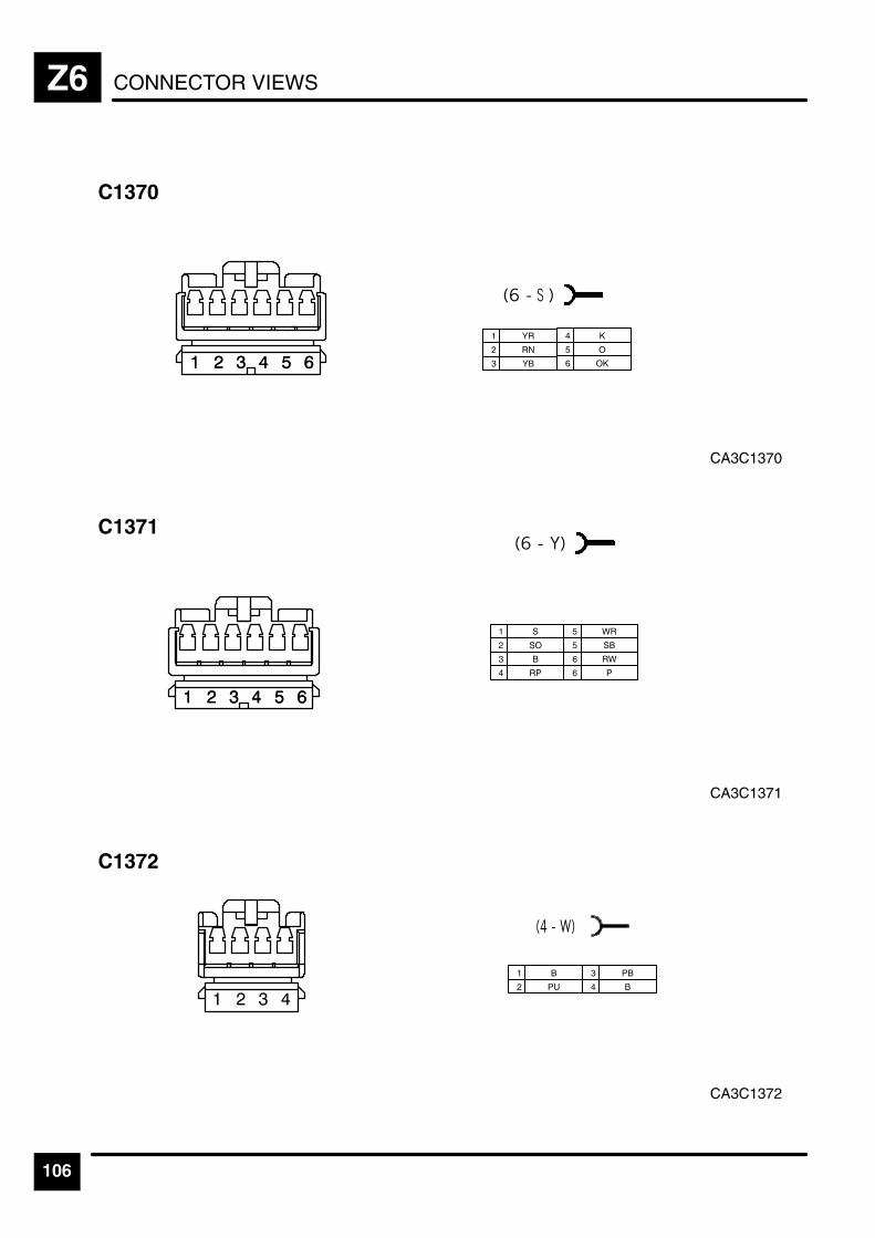
CONNECTOR VIEWSZ6
106
CA3C1370
C1370
1 YR
2 RN
3 YB
4 K
5 O
6 OK
CA3C1371
C1371
1 S
2 SO
3 B
4 RP
5 WR
5 SB
6 RW
6 P
CA3C1372
C1372
1 B
2 PU
3 PB
4 B
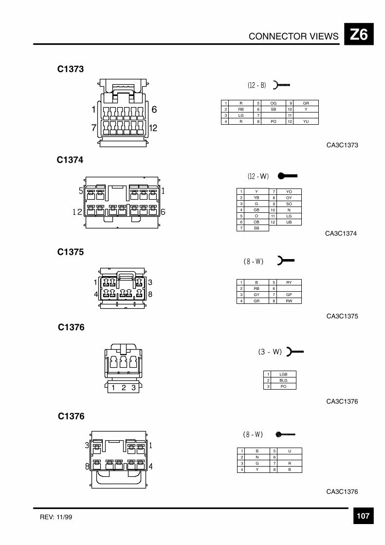
CONNECTOR VIEWS Z6
107REV: 11/99
CA3C1373
C1373
1 R
2 RB
3 LG
5 OG
6 SB
7
9 GR
10 Y
11
4 R 8 PO 12 YU
CA3C1374
C1374
1 Y
2 YB
3 G
5 O
6 OB
7 SB
9 SO
11 LG
4 GB
8 OY
12 UB
7 YO
10 N
CA3C1375
C1375
1 B
2 RB
3 GY
4 GR
5 RY
6
7 GP
8 RW
CA3C1376
C1376
1 B
2 N
3 G
4 Y
5 U
6
7 R
8 B
CA3C1376
C1376
1 LGB
2 BLG
3 PO

CONNECTOR VIEWSZ6
108 REV: 11/99
CA3C1377
C1377
1 Y
2 YB
3 G
4 GB
5 O
6 OB
7 SB
8
CA3C1378
C1378
1 Y
2 YB
3 G
5 O
6 OB
7 YO
8 OY
9 SO
10 P4 GB
7 SB
11 LG
12 UB
CA3C1381
C1381
1 U
2 G
3 R
CA3C1379
C1379
1 LG
2 R
3 PO
4 Y
5 YU
6 OG
CA3C1380
C1380
1 WY
1 Y
2 YW
3 GY
4 YG
5 GR
2 YB 6 SB

CONNECTOR VIEWS Z6
109REV: 11/99
CA3C1382
C1382
1 G
2
3 U
5
7
6 R
4
CA3C1383L
C1383L
1 Y
2 YB
3 LG
5 OG
6 SB
7
9 GR
10 Y
11
4 R 8 PO 12 YU
CA3C1383R
C1383R
1 Y
2 YB
3 LG
5 OG
6 SB
7
9 GR
10 Y
11
4 R 8 PO 12 YU
CA3C1384L
C1384L
1 B
2 PU
3 PB
4 B, B

CONNECTOR VIEWSZ6
110
CA3C1384R
C1384R
1 B
2 PU
3 PB
4 B, B
CA3C1385L
C1385L
1 YR
2 RN
3 YB
4 K
5 O
6 OK
CA3C1385R
C1385R
1 YR
2 RN
3 YB
4 K
5 O
6 OK
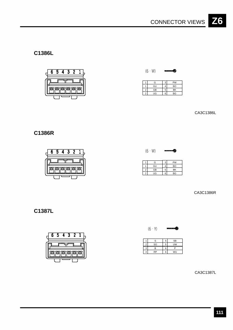
CONNECTOR VIEWS Z6
111
CA3C1386L
C1386L
1 G
1 GU
2 GB
2 UG
3 PW
4 BO
5 BK
6 BG
CA3C1386R
C1386R
1 G
1 GU
2 GB
2 UG
3 PW
4 BO
5 BK
6 BG
CA3C1387L
C1387L
1 S
2 SO
3 B
4 RP
5 SB
5 UW
6 P
6 WU

CONNECTOR VIEWSZ6
112
CA3C1387R
C1387R
1 S
2 SO
3 B
4 RP
5 SB
5 UW
6 P
6 WU
CA3C1388
C1388
1 B
2 R
3 N
CA3C1389
C1389
1 Y
2 U
3 B
4 G
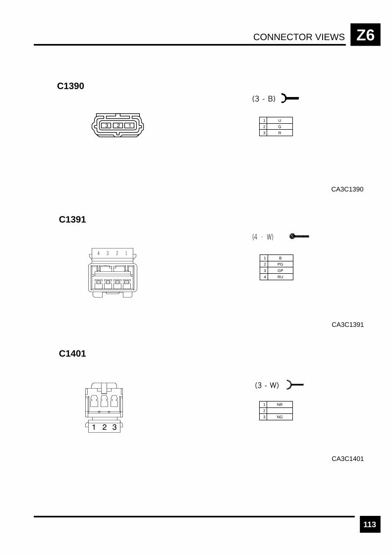
CONNECTOR VIEWS Z6
113
CA3C1390
C1390
1 U
2 G
3 R
CA3C1391
C1391
1 B
2 PG
3 GP
4 RU
CA3C1401
C1401
1 NR
2
3 NG

CONNECTOR VIEWSZ6
114
CA3C1402
C1402
1 NG
2 B
CA3C1403
C1403
1 NU
2
3 NB
CA3C0248R
C1404
1 NB
2 B
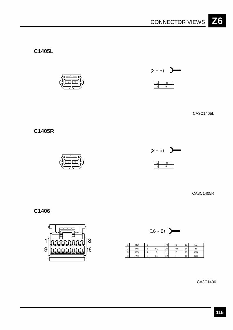
CONNECTOR VIEWS Z6
115
CA3C1405L
C1405L
1 PR
2 B
CA3C1405R
C1405R
1 PR
2 B
CA3C1406
C1406
1 BO
2 PR
3 PO
5
6 PU
7 B
9 B
4 YR 8 SG
10 PB
11 B
12 P
13 LG
14 R
15 OG
16 SW

CONNECTOR VIEWSZ6
116
CA3C1407L
C1407L
1 Y
2 R
3 G
5 BR
6 O
7 S
9
10 W
11 P
4 8 U 12 B
CA3C1407R
C1407R
1 Y
2 R
3 G
5 BR
6 O
7 S
9
10 W
11 P
4 8 U 12 B
CA3C1415
C1415
1 Y
2 U
3 W
4 G
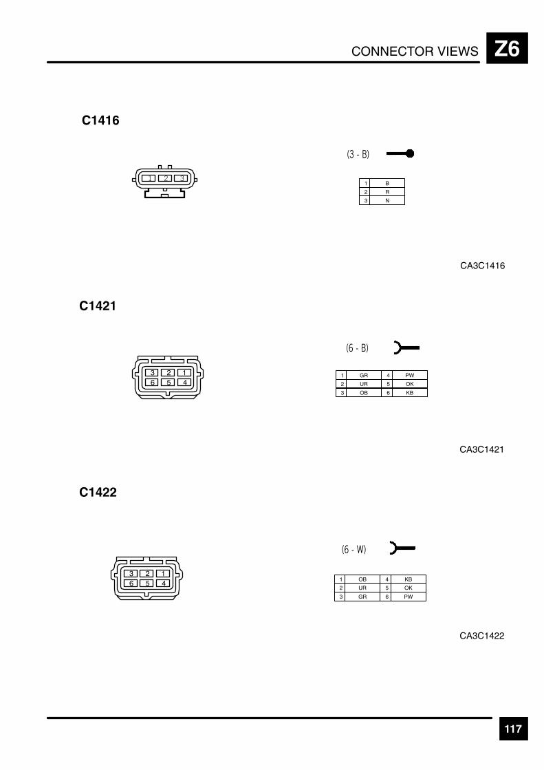
CONNECTOR VIEWS Z6
117
CA3C1416
C1416
1 B
2 R
3 N
CA3C1421
C1421
1 GR
2 UR
3 OB
4 PW
5 OK
6 KB
CA3C1422
C1422
1 OB
2 UR
3 GR
4 KB
5 OK
6 PW
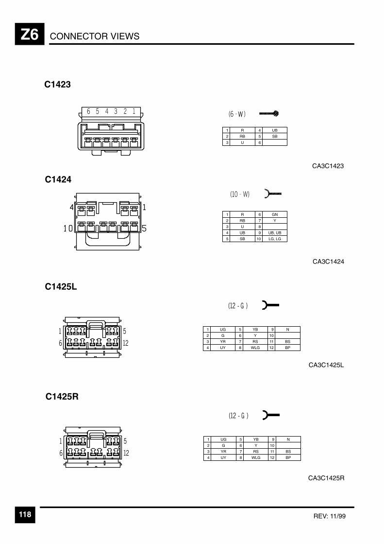
CONNECTOR VIEWSZ6
118 REV: 11/99
CA3C1423
C1423
1 R
2 RB
3 U
4 UB
5 SB
6
CA3C1425L
C1425L
1 UG
2 G
3 YR
5 YB
6 Y
7 RS
9 N
10
11 BS
4 UY 8 WLG 12 BP
CA3C1425R
C1425R
1 UG
2 G
3 YR
5 YB
6 Y
7 RS
9 N
10
11 BS
4 UY 8 WLG 12 BP
CA3C1424
C1424
1 R
2 RB
3 U
4 UB
5 SB 10 LG, LG
6 GN
7 Y
8
9 UB, UB
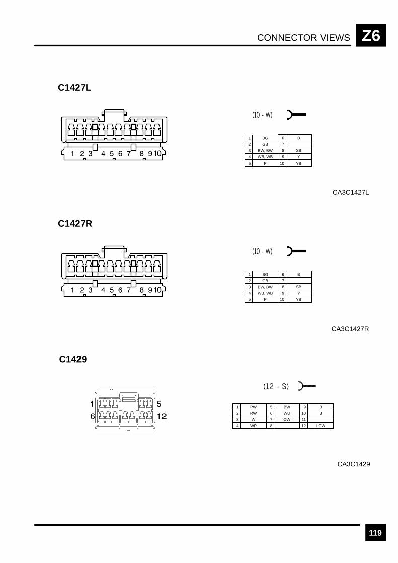
CONNECTOR VIEWS Z6
119
CA3C1427L
C1427L
1 BG
2 GB
3 BW, BW
4 WB, WB
5 P 10 YB
6 B
7
8 SB
9 Y
CA3C1427R
C1427R
1 BG
2 GB
3 BW, BW
4 WB, WB
5 P 10 YB
6 B
7
8 SB
9 Y
C1429
CA3C1429
1 PW
2 RW
3 W
5 BW
6 WU
7 OW
9 B
10 B
11
4 WP 8 12 LGW
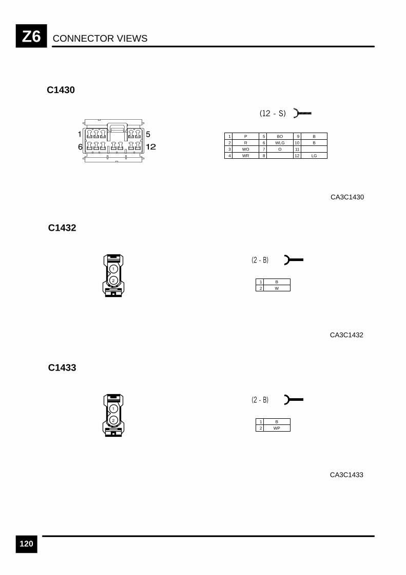
CONNECTOR VIEWSZ6
120
C1430
CA3C1430
1 P
2 R
3 WO
5 BO
6 WLG
7 O
9 B
10 B
11
4 WR 8 12 LG
C1432
CA3C1432
1 B
2 W
C1433
CA3C1433
1 B
2 WP
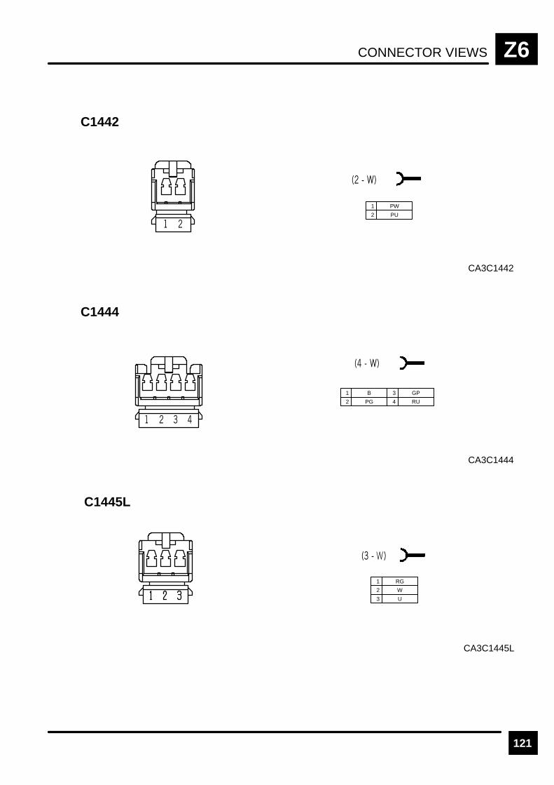
CONNECTOR VIEWS Z6
121
CA3C1442
C1442
1 PW
2 PU
CA3C1444
C1444
1 B
2 PG
3 GP
4 RU
C1445L
CA3C1445L
1 RG
2 W
3 U
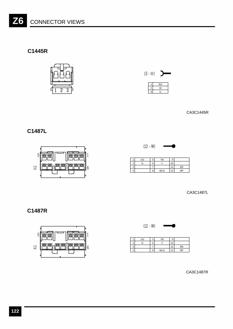
CONNECTOR VIEWSZ6
122
C1445R
CA3C1445R
1 RG
2 W
3 U
C1487L
CA3C1487L
1 UG
2 G
3
5 YB
6 Y
7
9
10
11 BS
4 8 WLG 12 BP
C1487R
CA3C1487R
1 UG
2 G
3
5 YB
6 Y
7
9
10
11 BS
4 8 WLG 12 BP

CONNECTOR VIEWS Z6
123
C1488L
CA3C1488L
1 UG
2 G
3
5 YB
6 Y
7
9
10
11 BS
4 8 WLG 12 BP
C1488R
CA3C1488R
1 UG
2 G
3
5 YB
6 Y
7
9
10
11 BS
4 8 WLG 12 BP
C1490
CA3C1490
1 N
2 RS
3 UY
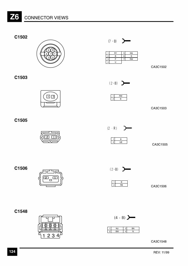
CONNECTOR VIEWSZ6
124 REV: 11/99
C1502
&"
1 RY
2 B
3 P
5 NG
7 RW
6 S
4 U
CA3C1502
C1503
CA3C1503
1 RW
2 B
CA3C1548
C1548
1 NU
2 BW
3 BN
4 N
CA3C1506
C1505
1 B
2 UB
C1506
1 B
2 RB
CA3C1505
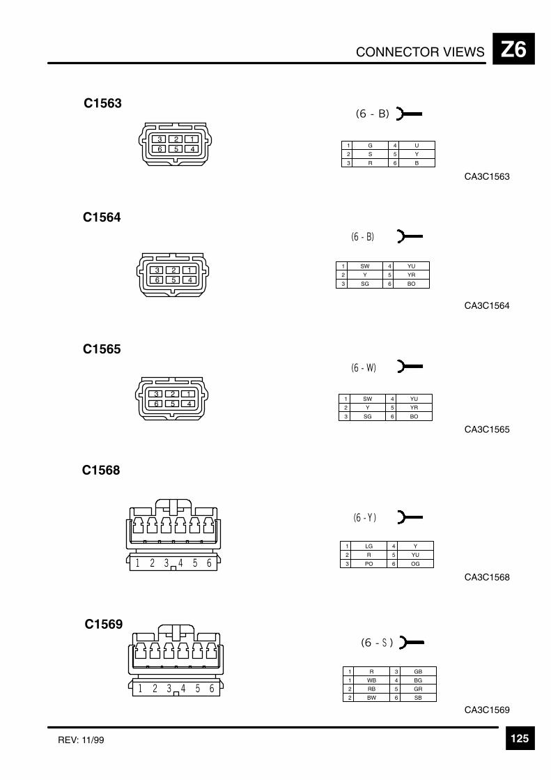
CONNECTOR VIEWS Z6
125REV: 11/99
C1563
CA3C1563
1 G
2 S
3 R
4 U
5 Y
6 B
CA3C1564
C1564
1 SW
2 Y
3 SG
4 YU
5 YR
6 BO
CA3C1565
C1565
1 SW
2 Y
3 SG
4 YU
5 YR
6 BO
CA3C1568
C1568
1 LG
2 R
3 PO
4 Y
5 YU
6 OG
CA3C1569
C1569
1 R
1 WB
2 RB
3 GB
4 BG
5 GR
2 BW 6 SB

CONNECTOR VIEWSZ6
126 REV: 11/99
CA3C1570
C1570
1 R
2 RB
3 U
4 UB
5 SB 10 LG
6 GN
7 Y
8
9 UB
CA3C1571
C1571
1 R
2 RB
3 U
4 UB
5 SB
6
CA3C1576
C1576
1 O
2 KR
3 LGR
5
6
7
9 WB
10
11 BP
4 NY 8 12 BR
C1577L
CA3C1577L
1 BW
2 WB
C1577R
CA3C1577R
1 BW
2 WB

CONNECTOR VIEWS Z6
127REV: 11/99
CA3C1579
C1579
1 OB
2 KB
3
6 UR
7 PW
8 OK
11 B
4 9
12
13
14
16
17
18
5 GR 10 15
19
20
CA3C1580
C1580
1 BO
2 PR
3 PO
5
6 PU
7 B
9 B
4 YR 8 SG
10 PB
11 B
12 P
13 LG
14 R
15 OG
16 SW
CA3C1584
C1584
1 RY
2 LGN
3 RY, RY
6 OK
7 OB
8 O
11 PR
4 GW
9 GN, GN
12 GP, GP
13 GU
14 GR
16 RU
17 P
18 K
5 G
10 RW, RW
15 GY
CA3C1583
C1583
1 B
2 PU
3 PB
4 B
5 LG
6 OG
CA3C1578
C1578
1 B
2 PU
3 PB
4 B
5 LG
6 UB

CONNECTOR VIEWSZ6
128 REV: 11/99
1 NK
2 W
3 YG
6
7 YP
8 NR
11 BG
4 YK 9
12 B
13
14 GP
16
17 WK
18 BS
5 K 10 BW 15
16 13 10 7 4 1
17 14 11 8 5 2
18 12 9 6 3
CA3C1584
C01584
CA3C1585
C1585
1 SN
2 SK
3 B
5 SR
6
7 SG
9
4 SU 8 S
10 SP
11 LG
12 SW
13 SB
14 SO
15 SY
"
&
CA3C1586
C1586
1 O
2 P
3 Y
4 W
5 R
6 G
7 N
8 U
9
9 6 3
8 5 2
7 4 1
CA3C1585
C1585
1 OP
2 BP
3 PY
6 OR
7 Y
8 BO
11 YG
4 RY 9 R
12
13 PW
14 YP
16 YU
17 BK
18
19 LG
5 BG 10 OG 15 YB 20
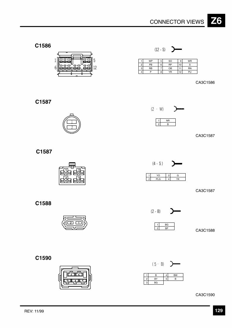
CONNECTOR VIEWS Z6
129REV: 11/99
CA3C1586
C1586
1 WP
2 PB
3 RB
5 SO
6 RP
7 OB
9 WR
10 S
11 RN
4 P 8 YR 12 PU
CA3C1587
C1587
1 NR
2 B
CA3C1588
C1588
1 BG
2 BP
CA3C1590
C1590
1 B
2 BY
3 BG
4 BW
5 B
CA3C1587
C1587
1 YO
2 PLG
3 G
4 YK

CONNECTOR VIEWSZ6
130
CA3C1591
C1591
1 SN
2 SB
3 B
6 SK
7 SR
8 S
10 SO
11 SU
4 SY 9 SW
12 LG
13 SP
5 SG
CA3C1593
C1593
1 NLG
2 RLG
3 ULG
4 B
CA3C1594
C1594
1 B
2 G

CONNECTOR VIEWS Z6
131
C1621
CA3C1621
1 B
2 BW
3 B
6 B
7
8 B
10 B
4 BW 9 BW
5 R


HARNESS ROUTING Z8
1
RH Body Wire Harness

HARNESS ROUTINGZ8
2
LH Body Wire Harness
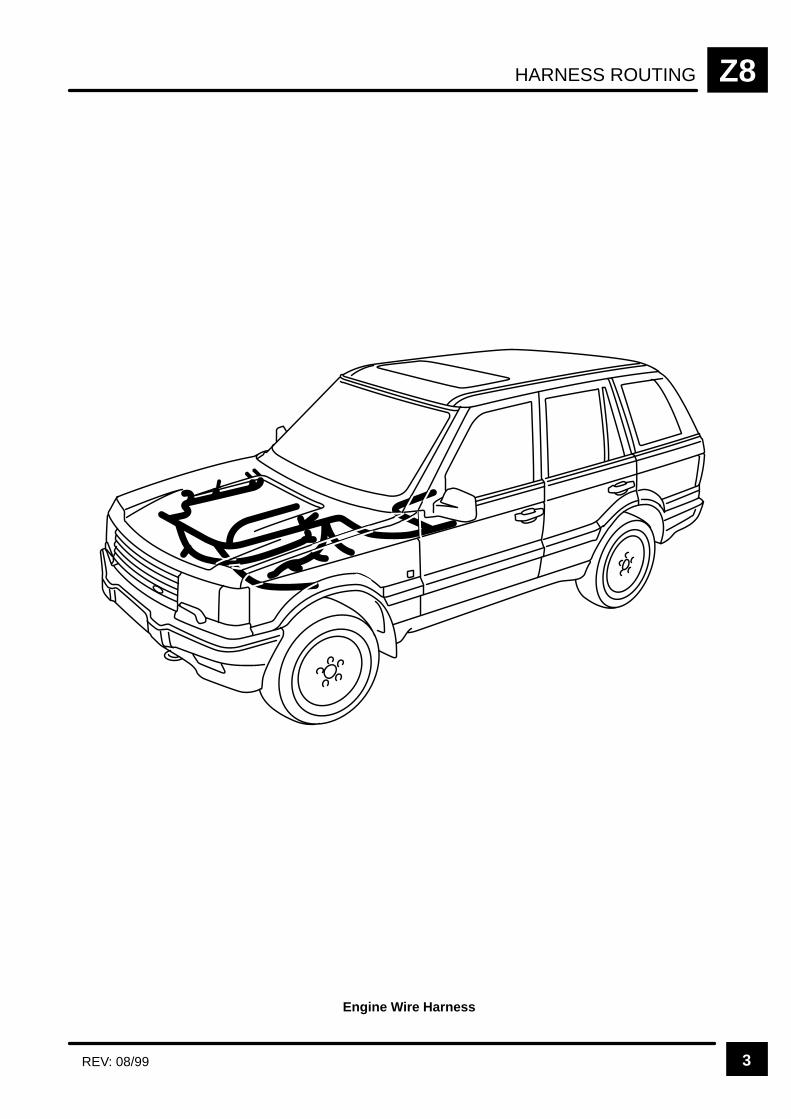
HARNESS ROUTING Z8
3REV: 08/99
Engine Wire Harness
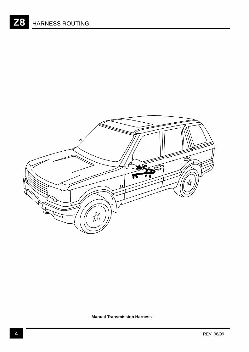
HARNESS ROUTINGZ8
4 REV: 08/99
Manual Transmission Harness
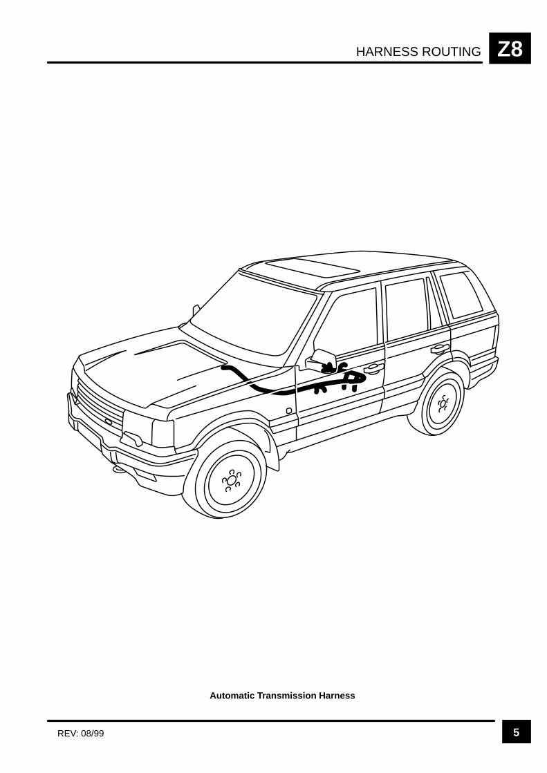
HARNESS ROUTING Z8
5REV: 08/99
Automatic Transmission Harness

HARNESS ROUTINGZ8
6 REV: 08/99
Lower Tailgate Harness
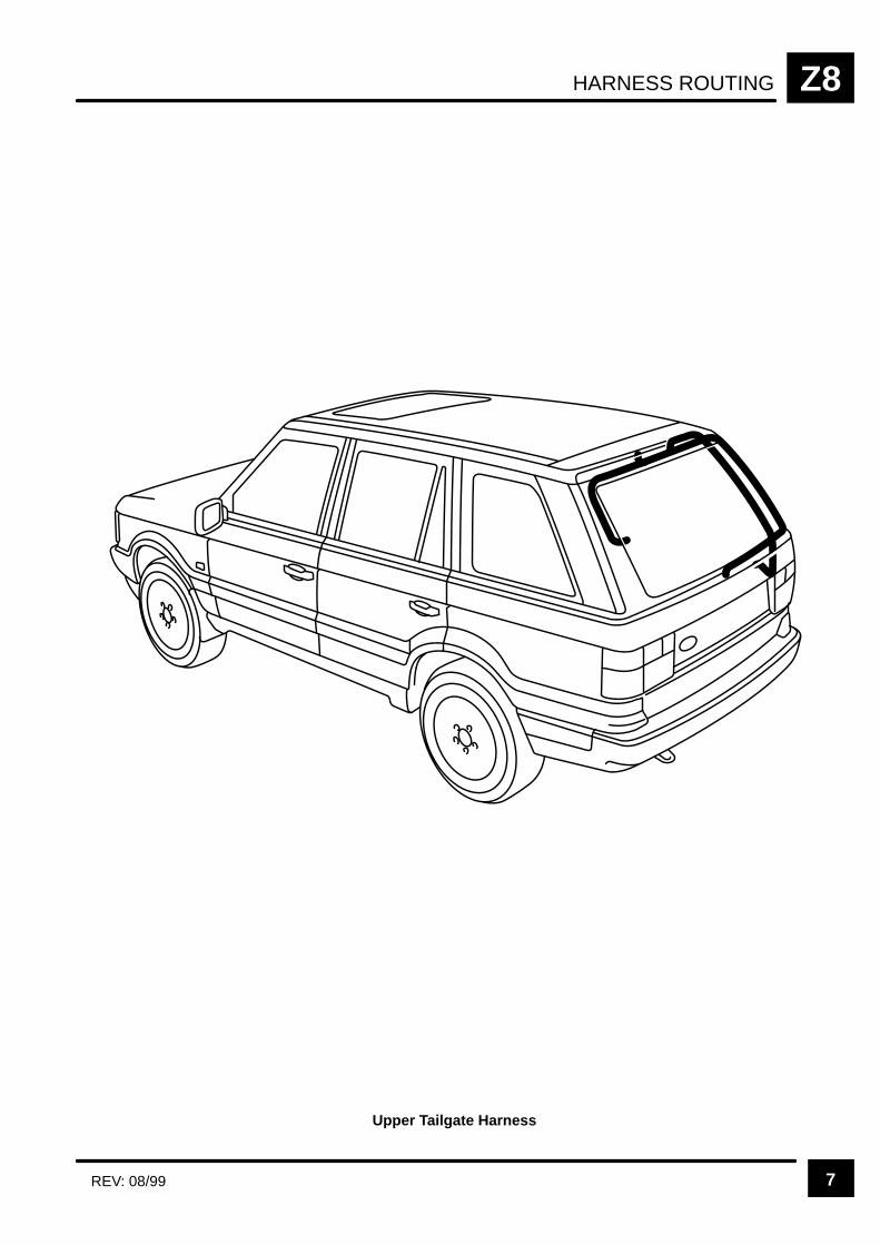
HARNESS ROUTING Z8
7REV: 08/99
Upper Tailgate Harness
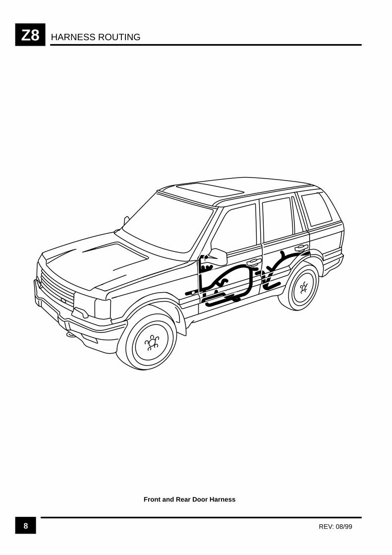
HARNESS ROUTINGZ8
8 REV: 08/99
Front and Rear Door Harness
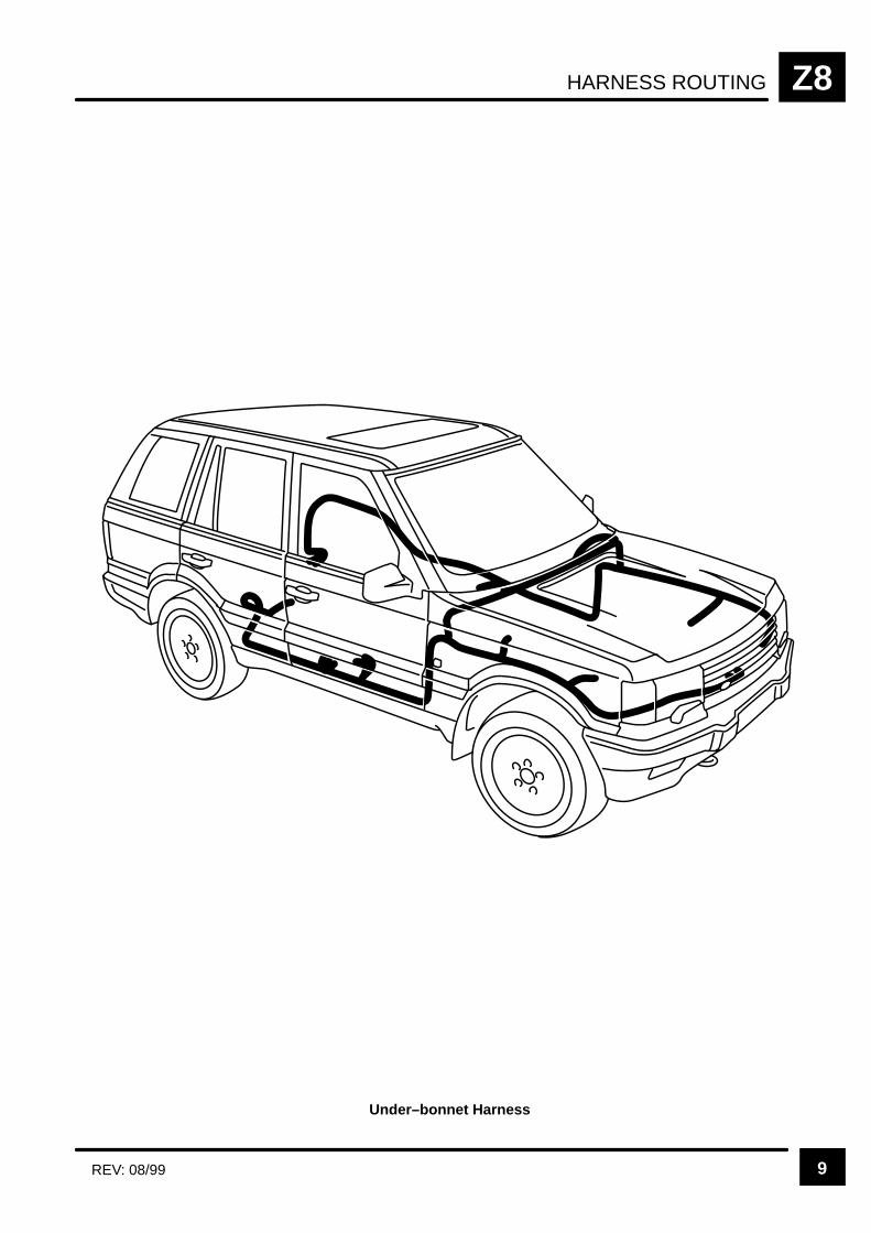
HARNESS ROUTING Z8
9REV: 08/99
Under–bonnet Harness
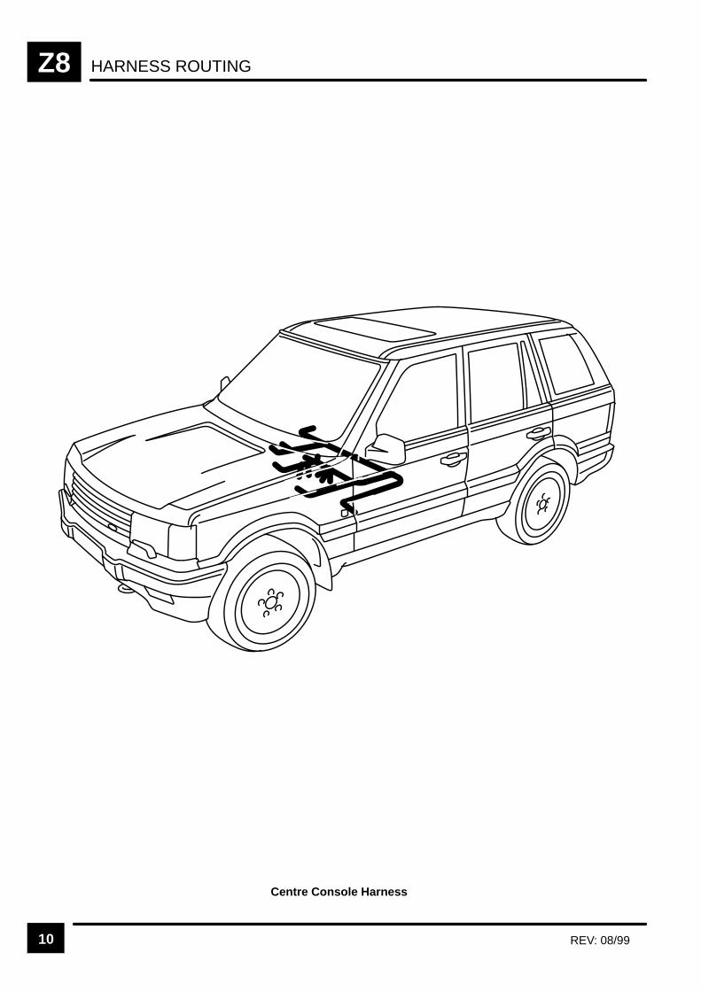
HARNESS ROUTINGZ8
10 REV: 08/99
Centre Console Harness
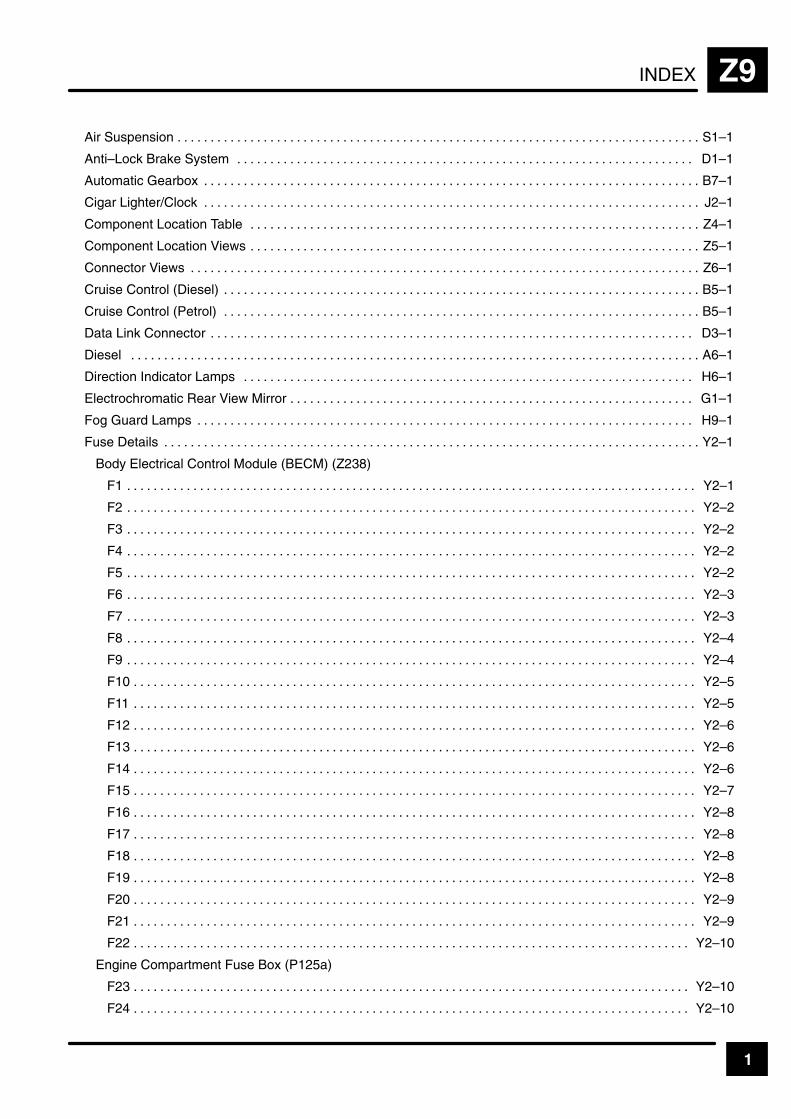
INDEX Z9
1
Air Suspension S1–1. . . . . . . . . . . . . . . . . . . . . . . . . . . . . . . . . . . . . . . . . . . . . . . . . . . . . . . . . . . . . . . . . . . . . . . . . . . . . . .
Anti–Lock Brake System D1–1. . . . . . . . . . . . . . . . . . . . . . . . . . . . . . . . . . . . . . . . . . . . . . . . . . . . . . . . . . . . . . . . . . . . .
Automatic Gearbox B7–1. . . . . . . . . . . . . . . . . . . . . . . . . . . . . . . . . . . . . . . . . . . . . . . . . . . . . . . . . . . . . . . . . . . . . . . . . . .
Cigar Lighter/Clock J2–1. . . . . . . . . . . . . . . . . . . . . . . . . . . . . . . . . . . . . . . . . . . . . . . . . . . . . . . . . . . . . . . . . . . . . . . . . . .
Component Location Table Z4–1. . . . . . . . . . . . . . . . . . . . . . . . . . . . . . . . . . . . . . . . . . . . . . . . . . . . . . . . . . . . . . . . . . . .
Component Location Views Z5–1. . . . . . . . . . . . . . . . . . . . . . . . . . . . . . . . . . . . . . . . . . . . . . . . . . . . . . . . . . . . . . . . . . . .
Connector Views Z6–1. . . . . . . . . . . . . . . . . . . . . . . . . . . . . . . . . . . . . . . . . . . . . . . . . . . . . . . . . . . . . . . . . . . . . . . . . . . . .
Cruise Control (Diesel) B5–1. . . . . . . . . . . . . . . . . . . . . . . . . . . . . . . . . . . . . . . . . . . . . . . . . . . . . . . . . . . . . . . . . . . . . . . .
Cruise Control (Petrol) B5–1. . . . . . . . . . . . . . . . . . . . . . . . . . . . . . . . . . . . . . . . . . . . . . . . . . . . . . . . . . . . . . . . . . . . . . . .
Data Link Connector D3–1. . . . . . . . . . . . . . . . . . . . . . . . . . . . . . . . . . . . . . . . . . . . . . . . . . . . . . . . . . . . . . . . . . . . . . . . .
Diesel A6–1. . . . . . . . . . . . . . . . . . . . . . . . . . . . . . . . . . . . . . . . . . . . . . . . . . . . . . . . . . . . . . . . . . . . . . . . . . . . . . . . . . . . . .
Direction Indicator Lamps H6–1. . . . . . . . . . . . . . . . . . . . . . . . . . . . . . . . . . . . . . . . . . . . . . . . . . . . . . . . . . . . . . . . . . . .
Electrochromatic Rear View Mirror G1–1. . . . . . . . . . . . . . . . . . . . . . . . . . . . . . . . . . . . . . . . . . . . . . . . . . . . . . . . . . . . .
Fog Guard Lamps H9–1. . . . . . . . . . . . . . . . . . . . . . . . . . . . . . . . . . . . . . . . . . . . . . . . . . . . . . . . . . . . . . . . . . . . . . . . . . .
Fuse Details Y2–1. . . . . . . . . . . . . . . . . . . . . . . . . . . . . . . . . . . . . . . . . . . . . . . . . . . . . . . . . . . . . . . . . . . . . . . . . . . . . . . . .
Body Electrical Control Module (BECM) (Z238)
F1 Y2–1. . . . . . . . . . . . . . . . . . . . . . . . . . . . . . . . . . . . . . . . . . . . . . . . . . . . . . . . . . . . . . . . . . . . . . . . . . . . . . . . . . . . . .
F2 Y2–2. . . . . . . . . . . . . . . . . . . . . . . . . . . . . . . . . . . . . . . . . . . . . . . . . . . . . . . . . . . . . . . . . . . . . . . . . . . . . . . . . . . . . .
F3 Y2–2. . . . . . . . . . . . . . . . . . . . . . . . . . . . . . . . . . . . . . . . . . . . . . . . . . . . . . . . . . . . . . . . . . . . . . . . . . . . . . . . . . . . . .
F4 Y2–2. . . . . . . . . . . . . . . . . . . . . . . . . . . . . . . . . . . . . . . . . . . . . . . . . . . . . . . . . . . . . . . . . . . . . . . . . . . . . . . . . . . . . .
F5 Y2–2. . . . . . . . . . . . . . . . . . . . . . . . . . . . . . . . . . . . . . . . . . . . . . . . . . . . . . . . . . . . . . . . . . . . . . . . . . . . . . . . . . . . . .
F6 Y2–3. . . . . . . . . . . . . . . . . . . . . . . . . . . . . . . . . . . . . . . . . . . . . . . . . . . . . . . . . . . . . . . . . . . . . . . . . . . . . . . . . . . . . .
F7 Y2–3. . . . . . . . . . . . . . . . . . . . . . . . . . . . . . . . . . . . . . . . . . . . . . . . . . . . . . . . . . . . . . . . . . . . . . . . . . . . . . . . . . . . . .
F8 Y2–4. . . . . . . . . . . . . . . . . . . . . . . . . . . . . . . . . . . . . . . . . . . . . . . . . . . . . . . . . . . . . . . . . . . . . . . . . . . . . . . . . . . . . .
F9 Y2–4. . . . . . . . . . . . . . . . . . . . . . . . . . . . . . . . . . . . . . . . . . . . . . . . . . . . . . . . . . . . . . . . . . . . . . . . . . . . . . . . . . . . . .
F10 Y2–5. . . . . . . . . . . . . . . . . . . . . . . . . . . . . . . . . . . . . . . . . . . . . . . . . . . . . . . . . . . . . . . . . . . . . . . . . . . . . . . . . . . . .
F11 Y2–5. . . . . . . . . . . . . . . . . . . . . . . . . . . . . . . . . . . . . . . . . . . . . . . . . . . . . . . . . . . . . . . . . . . . . . . . . . . . . . . . . . . . .
F12 Y2–6. . . . . . . . . . . . . . . . . . . . . . . . . . . . . . . . . . . . . . . . . . . . . . . . . . . . . . . . . . . . . . . . . . . . . . . . . . . . . . . . . . . . .
F13 Y2–6. . . . . . . . . . . . . . . . . . . . . . . . . . . . . . . . . . . . . . . . . . . . . . . . . . . . . . . . . . . . . . . . . . . . . . . . . . . . . . . . . . . . .
F14 Y2–6. . . . . . . . . . . . . . . . . . . . . . . . . . . . . . . . . . . . . . . . . . . . . . . . . . . . . . . . . . . . . . . . . . . . . . . . . . . . . . . . . . . . .
F15 Y2–7. . . . . . . . . . . . . . . . . . . . . . . . . . . . . . . . . . . . . . . . . . . . . . . . . . . . . . . . . . . . . . . . . . . . . . . . . . . . . . . . . . . . .
F16 Y2–8. . . . . . . . . . . . . . . . . . . . . . . . . . . . . . . . . . . . . . . . . . . . . . . . . . . . . . . . . . . . . . . . . . . . . . . . . . . . . . . . . . . . .
F17 Y2–8. . . . . . . . . . . . . . . . . . . . . . . . . . . . . . . . . . . . . . . . . . . . . . . . . . . . . . . . . . . . . . . . . . . . . . . . . . . . . . . . . . . . .
F18 Y2–8. . . . . . . . . . . . . . . . . . . . . . . . . . . . . . . . . . . . . . . . . . . . . . . . . . . . . . . . . . . . . . . . . . . . . . . . . . . . . . . . . . . . .
F19 Y2–8. . . . . . . . . . . . . . . . . . . . . . . . . . . . . . . . . . . . . . . . . . . . . . . . . . . . . . . . . . . . . . . . . . . . . . . . . . . . . . . . . . . . .
F20 Y2–9. . . . . . . . . . . . . . . . . . . . . . . . . . . . . . . . . . . . . . . . . . . . . . . . . . . . . . . . . . . . . . . . . . . . . . . . . . . . . . . . . . . . .
F21 Y2–9. . . . . . . . . . . . . . . . . . . . . . . . . . . . . . . . . . . . . . . . . . . . . . . . . . . . . . . . . . . . . . . . . . . . . . . . . . . . . . . . . . . . .
F22 Y2–10. . . . . . . . . . . . . . . . . . . . . . . . . . . . . . . . . . . . . . . . . . . . . . . . . . . . . . . . . . . . . . . . . . . . . . . . . . . . . . . . . . . .
Engine Compartment Fuse Box (P125a)
F23 Y2–10. . . . . . . . . . . . . . . . . . . . . . . . . . . . . . . . . . . . . . . . . . . . . . . . . . . . . . . . . . . . . . . . . . . . . . . . . . . . . . . . . . . .
F24 Y2–10. . . . . . . . . . . . . . . . . . . . . . . . . . . . . . . . . . . . . . . . . . . . . . . . . . . . . . . . . . . . . . . . . . . . . . . . . . . . . . . . . . . .
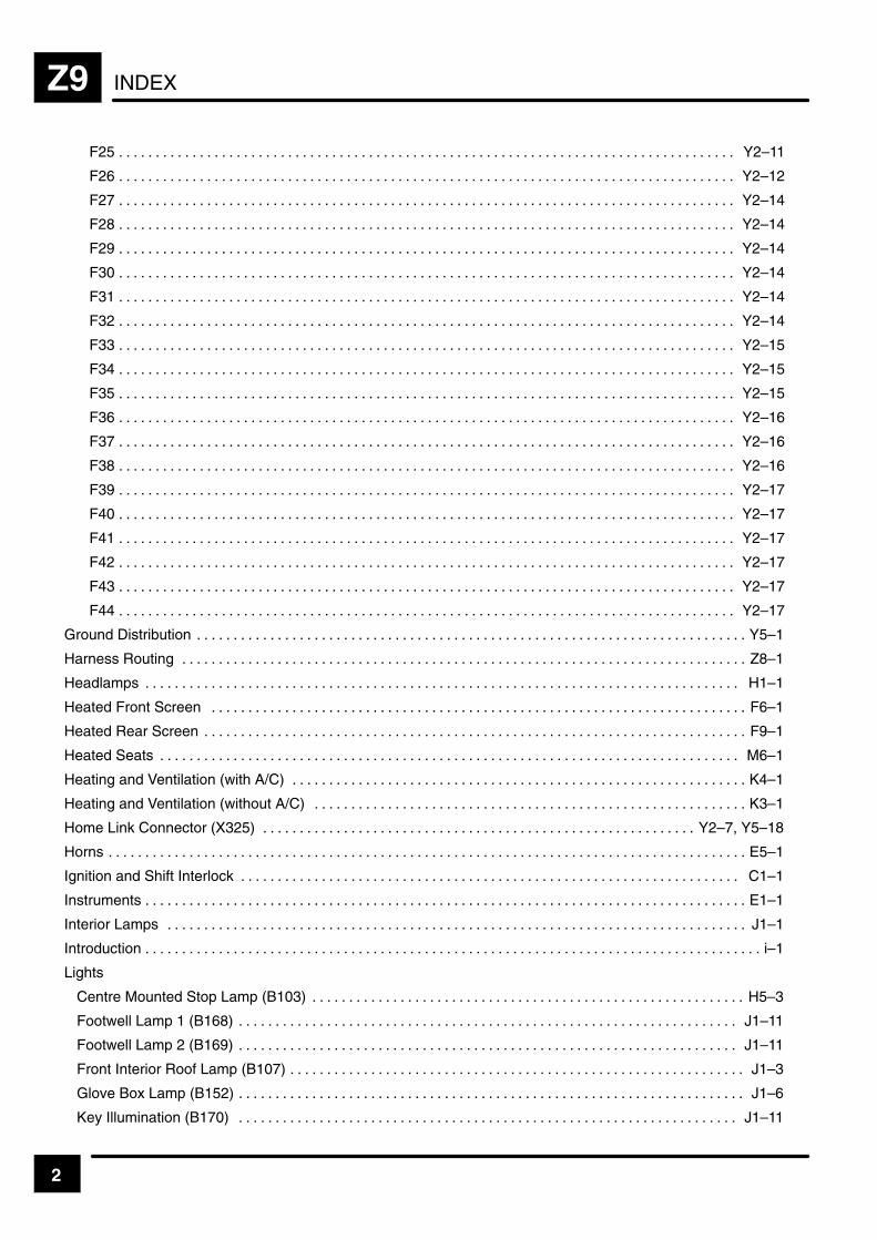
INDEXZ9
2
F25 Y2–11. . . . . . . . . . . . . . . . . . . . . . . . . . . . . . . . . . . . . . . . . . . . . . . . . . . . . . . . . . . . . . . . . . . . . . . . . . . . . . . . . . . .
F26 Y2–12. . . . . . . . . . . . . . . . . . . . . . . . . . . . . . . . . . . . . . . . . . . . . . . . . . . . . . . . . . . . . . . . . . . . . . . . . . . . . . . . . . . .
F27 Y2–14. . . . . . . . . . . . . . . . . . . . . . . . . . . . . . . . . . . . . . . . . . . . . . . . . . . . . . . . . . . . . . . . . . . . . . . . . . . . . . . . . . . .
F28 Y2–14. . . . . . . . . . . . . . . . . . . . . . . . . . . . . . . . . . . . . . . . . . . . . . . . . . . . . . . . . . . . . . . . . . . . . . . . . . . . . . . . . . . .
F29 Y2–14. . . . . . . . . . . . . . . . . . . . . . . . . . . . . . . . . . . . . . . . . . . . . . . . . . . . . . . . . . . . . . . . . . . . . . . . . . . . . . . . . . . .
F30 Y2–14. . . . . . . . . . . . . . . . . . . . . . . . . . . . . . . . . . . . . . . . . . . . . . . . . . . . . . . . . . . . . . . . . . . . . . . . . . . . . . . . . . . .
F31 Y2–14. . . . . . . . . . . . . . . . . . . . . . . . . . . . . . . . . . . . . . . . . . . . . . . . . . . . . . . . . . . . . . . . . . . . . . . . . . . . . . . . . . . .
F32 Y2–14. . . . . . . . . . . . . . . . . . . . . . . . . . . . . . . . . . . . . . . . . . . . . . . . . . . . . . . . . . . . . . . . . . . . . . . . . . . . . . . . . . . .
F33 Y2–15. . . . . . . . . . . . . . . . . . . . . . . . . . . . . . . . . . . . . . . . . . . . . . . . . . . . . . . . . . . . . . . . . . . . . . . . . . . . . . . . . . . .
F34 Y2–15. . . . . . . . . . . . . . . . . . . . . . . . . . . . . . . . . . . . . . . . . . . . . . . . . . . . . . . . . . . . . . . . . . . . . . . . . . . . . . . . . . . .
F35 Y2–15. . . . . . . . . . . . . . . . . . . . . . . . . . . . . . . . . . . . . . . . . . . . . . . . . . . . . . . . . . . . . . . . . . . . . . . . . . . . . . . . . . . .
F36 Y2–16. . . . . . . . . . . . . . . . . . . . . . . . . . . . . . . . . . . . . . . . . . . . . . . . . . . . . . . . . . . . . . . . . . . . . . . . . . . . . . . . . . . .
F37 Y2–16. . . . . . . . . . . . . . . . . . . . . . . . . . . . . . . . . . . . . . . . . . . . . . . . . . . . . . . . . . . . . . . . . . . . . . . . . . . . . . . . . . . .
F38 Y2–16. . . . . . . . . . . . . . . . . . . . . . . . . . . . . . . . . . . . . . . . . . . . . . . . . . . . . . . . . . . . . . . . . . . . . . . . . . . . . . . . . . . .
F39 Y2–17. . . . . . . . . . . . . . . . . . . . . . . . . . . . . . . . . . . . . . . . . . . . . . . . . . . . . . . . . . . . . . . . . . . . . . . . . . . . . . . . . . . .
F40 Y2–17. . . . . . . . . . . . . . . . . . . . . . . . . . . . . . . . . . . . . . . . . . . . . . . . . . . . . . . . . . . . . . . . . . . . . . . . . . . . . . . . . . . .
F41 Y2–17. . . . . . . . . . . . . . . . . . . . . . . . . . . . . . . . . . . . . . . . . . . . . . . . . . . . . . . . . . . . . . . . . . . . . . . . . . . . . . . . . . . .
F42 Y2–17. . . . . . . . . . . . . . . . . . . . . . . . . . . . . . . . . . . . . . . . . . . . . . . . . . . . . . . . . . . . . . . . . . . . . . . . . . . . . . . . . . . .
F43 Y2–17. . . . . . . . . . . . . . . . . . . . . . . . . . . . . . . . . . . . . . . . . . . . . . . . . . . . . . . . . . . . . . . . . . . . . . . . . . . . . . . . . . . .
F44 Y2–17. . . . . . . . . . . . . . . . . . . . . . . . . . . . . . . . . . . . . . . . . . . . . . . . . . . . . . . . . . . . . . . . . . . . . . . . . . . . . . . . . . . .
Ground Distribution Y5–1. . . . . . . . . . . . . . . . . . . . . . . . . . . . . . . . . . . . . . . . . . . . . . . . . . . . . . . . . . . . . . . . . . . . . . . . . . .
Harness Routing Z8–1. . . . . . . . . . . . . . . . . . . . . . . . . . . . . . . . . . . . . . . . . . . . . . . . . . . . . . . . . . . . . . . . . . . . . . . . . . . . .
Headlamps H1–1. . . . . . . . . . . . . . . . . . . . . . . . . . . . . . . . . . . . . . . . . . . . . . . . . . . . . . . . . . . . . . . . . . . . . . . . . . . . . . . . .
Heated Front Screen F6–1. . . . . . . . . . . . . . . . . . . . . . . . . . . . . . . . . . . . . . . . . . . . . . . . . . . . . . . . . . . . . . . . . . . . . . . . .
Heated Rear Screen F9–1. . . . . . . . . . . . . . . . . . . . . . . . . . . . . . . . . . . . . . . . . . . . . . . . . . . . . . . . . . . . . . . . . . . . . . . . . .
Heated Seats M6–1. . . . . . . . . . . . . . . . . . . . . . . . . . . . . . . . . . . . . . . . . . . . . . . . . . . . . . . . . . . . . . . . . . . . . . . . . . . . . . .
Heating and Ventilation (with A/C) K4–1. . . . . . . . . . . . . . . . . . . . . . . . . . . . . . . . . . . . . . . . . . . . . . . . . . . . . . . . . . . . . .
Heating and Ventilation (without A/C) K3–1. . . . . . . . . . . . . . . . . . . . . . . . . . . . . . . . . . . . . . . . . . . . . . . . . . . . . . . . . . .
Home Link Connector (X325) Y2–7, Y5–18. . . . . . . . . . . . . . . . . . . . . . . . . . . . . . . . . . . . . . . . . . . . . . . . . . . . . . . . . . .
Horns E5–1. . . . . . . . . . . . . . . . . . . . . . . . . . . . . . . . . . . . . . . . . . . . . . . . . . . . . . . . . . . . . . . . . . . . . . . . . . . . . . . . . . . . . . .
Ignition and Shift Interlock C1–1. . . . . . . . . . . . . . . . . . . . . . . . . . . . . . . . . . . . . . . . . . . . . . . . . . . . . . . . . . . . . . . . . . . .
Instruments E1–1. . . . . . . . . . . . . . . . . . . . . . . . . . . . . . . . . . . . . . . . . . . . . . . . . . . . . . . . . . . . . . . . . . . . . . . . . . . . . . . . . .
Interior Lamps J1–1. . . . . . . . . . . . . . . . . . . . . . . . . . . . . . . . . . . . . . . . . . . . . . . . . . . . . . . . . . . . . . . . . . . . . . . . . . . . . . .
Introduction i–1. . . . . . . . . . . . . . . . . . . . . . . . . . . . . . . . . . . . . . . . . . . . . . . . . . . . . . . . . . . . . . . . . . . . . . . . . . . . . . . . . . . .
Lights
Centre Mounted Stop Lamp (B103) H5–3. . . . . . . . . . . . . . . . . . . . . . . . . . . . . . . . . . . . . . . . . . . . . . . . . . . . . . . . . . .
Footwell Lamp 1 (B168) J1–11. . . . . . . . . . . . . . . . . . . . . . . . . . . . . . . . . . . . . . . . . . . . . . . . . . . . . . . . . . . . . . . . . . . .
Footwell Lamp 2 (B169) J1–11. . . . . . . . . . . . . . . . . . . . . . . . . . . . . . . . . . . . . . . . . . . . . . . . . . . . . . . . . . . . . . . . . . . .
Front Interior Roof Lamp (B107) J1–3. . . . . . . . . . . . . . . . . . . . . . . . . . . . . . . . . . . . . . . . . . . . . . . . . . . . . . . . . . . . . .
Glove Box Lamp (B152) J1–6. . . . . . . . . . . . . . . . . . . . . . . . . . . . . . . . . . . . . . . . . . . . . . . . . . . . . . . . . . . . . . . . . . . . .
Key Illumination (B170) J1–11. . . . . . . . . . . . . . . . . . . . . . . . . . . . . . . . . . . . . . . . . . . . . . . . . . . . . . . . . . . . . . . . . . . .

INDEX Z9
3
Left Front Door Puddle Lamp (B114) J1–12. . . . . . . . . . . . . . . . . . . . . . . . . . . . . . . . . . . . . . . . . . . . . . . . . . . . . . . . .
Left Front Fog Lamp (B184) H9–2. . . . . . . . . . . . . . . . . . . . . . . . . . . . . . . . . . . . . . . . . . . . . . . . . . . . . . . . . . . . . . . . .
Left Front Indicator Lamp (B153) H6–4. . . . . . . . . . . . . . . . . . . . . . . . . . . . . . . . . . . . . . . . . . . . . . . . . . . . . . . . . . . . .
Left Front Lamp Assembly (B115) H4–3. . . . . . . . . . . . . . . . . . . . . . . . . . . . . . . . . . . . . . . . . . . . . . . . . . . . . . . . . . . .
Left Headlamp (B116) H1–3. . . . . . . . . . . . . . . . . . . . . . . . . . . . . . . . . . . . . . . . . . . . . . . . . . . . . . . . . . . . . . . . . . . . . . .
Left Interior Lights (B180) J1–7. . . . . . . . . . . . . . . . . . . . . . . . . . . . . . . . . . . . . . . . . . . . . . . . . . . . . . . . . . . . . . . . . . .
Left Number Plate Lamp (B120) H4–5. . . . . . . . . . . . . . . . . . . . . . . . . . . . . . . . . . . . . . . . . . . . . . . . . . . . . . . . . . . . . .
Left Rear Door Puddle Lamp (B149) J1–12. . . . . . . . . . . . . . . . . . . . . . . . . . . . . . . . . . . . . . . . . . . . . . . . . . . . . . . . .
Left Rear Lamp Assembly (B175) H4–4. . . . . . . . . . . . . . . . . . . . . . . . . . . . . . . . . . . . . . . . . . . . . . . . . . . . . . . . . . . .
Left Repeater Lamp (B122) H6–5. . . . . . . . . . . . . . . . . . . . . . . . . . . . . . . . . . . . . . . . . . . . . . . . . . . . . . . . . . . . . . . . . .
Left Tailgate Lights (B177) H9–3. . . . . . . . . . . . . . . . . . . . . . . . . . . . . . . . . . . . . . . . . . . . . . . . . . . . . . . . . . . . . . . . . . .
Rear Footwell Lamp (B182) J1–11. . . . . . . . . . . . . . . . . . . . . . . . . . . . . . . . . . . . . . . . . . . . . . . . . . . . . . . . . . . . . . . . .
Rear Load Space Lamp (B174) J1–3. . . . . . . . . . . . . . . . . . . . . . . . . . . . . . . . . . . . . . . . . . . . . . . . . . . . . . . . . . . . . .
Right Front Door Puddle Lamp (B127) J1–12. . . . . . . . . . . . . . . . . . . . . . . . . . . . . . . . . . . . . . . . . . . . . . . . . . . . . . .
Right Front Fog Lamp (B183) H9–2. . . . . . . . . . . . . . . . . . . . . . . . . . . . . . . . . . . . . . . . . . . . . . . . . . . . . . . . . . . . . . . .
Right Front Indicator Lamp (B154) H6–4. . . . . . . . . . . . . . . . . . . . . . . . . . . . . . . . . . . . . . . . . . . . . . . . . . . . . . . . . . . .
Right Front Lamp Assembly (B128) H4–3. . . . . . . . . . . . . . . . . . . . . . . . . . . . . . . . . . . . . . . . . . . . . . . . . . . . . . . . . . .
Right Headlamp (B130) H1–3. . . . . . . . . . . . . . . . . . . . . . . . . . . . . . . . . . . . . . . . . . . . . . . . . . . . . . . . . . . . . . . . . . . . .
Right Interior Lights (B179) J1–3. . . . . . . . . . . . . . . . . . . . . . . . . . . . . . . . . . . . . . . . . . . . . . . . . . . . . . . . . . . . . . . . . .
Right Number Plate Lamp (B134) H4–5. . . . . . . . . . . . . . . . . . . . . . . . . . . . . . . . . . . . . . . . . . . . . . . . . . . . . . . . . . . .
Right Rear Door Puddle Lamp (B150) J1–12. . . . . . . . . . . . . . . . . . . . . . . . . . . . . . . . . . . . . . . . . . . . . . . . . . . . . . . .
Right Rear Lamp Assembly (B176) H4–4. . . . . . . . . . . . . . . . . . . . . . . . . . . . . . . . . . . . . . . . . . . . . . . . . . . . . . . . . . .
Right Repeater Lamp (B137) H6–5. . . . . . . . . . . . . . . . . . . . . . . . . . . . . . . . . . . . . . . . . . . . . . . . . . . . . . . . . . . . . . . .
Right Tailgate Lights (B178) H9–3. . . . . . . . . . . . . . . . . . . . . . . . . . . . . . . . . . . . . . . . . . . . . . . . . . . . . . . . . . . . . . . . .
Sun–visor Lamp 1 (B172) J1–7. . . . . . . . . . . . . . . . . . . . . . . . . . . . . . . . . . . . . . . . . . . . . . . . . . . . . . . . . . . . . . . . . . .
Sun–visor Lamp 2 (B173) J1–7. . . . . . . . . . . . . . . . . . . . . . . . . . . . . . . . . . . . . . . . . . . . . . . . . . . . . . . . . . . . . . . . . . .
Memory Mirrors M7–1. . . . . . . . . . . . . . . . . . . . . . . . . . . . . . . . . . . . . . . . . . . . . . . . . . . . . . . . . . . . . . . . . . . . . . . . . . . . .
Memory Seats M4–1. . . . . . . . . . . . . . . . . . . . . . . . . . . . . . . . . . . . . . . . . . . . . . . . . . . . . . . . . . . . . . . . . . . . . . . . . . . . . .
Navigation System E9–1. . . . . . . . . . . . . . . . . . . . . . . . . . . . . . . . . . . . . . . . . . . . . . . . . . . . . . . . . . . . . . . . . . . . . . . . . . .
Power Distribution Y1–1. . . . . . . . . . . . . . . . . . . . . . . . . . . . . . . . . . . . . . . . . . . . . . . . . . . . . . . . . . . . . . . . . . . . . . . . . . . .
Body Electrical Control Module (BECM) (Z238)
RL10 Y1–2. . . . . . . . . . . . . . . . . . . . . . . . . . . . . . . . . . . . . . . . . . . . . . . . . . . . . . . . . . . . . . . . . . . . . . . . . . . . . . . . . . .
Engine Compartment Fuse Box (P125a)
MF 1 Y1–2. . . . . . . . . . . . . . . . . . . . . . . . . . . . . . . . . . . . . . . . . . . . . . . . . . . . . . . . . . . . . . . . . . . . . . . . . . . . . . . . . . .
MF 2 Y1–2. . . . . . . . . . . . . . . . . . . . . . . . . . . . . . . . . . . . . . . . . . . . . . . . . . . . . . . . . . . . . . . . . . . . . . . . . . . . . . . . . . .
MF 3 Y1–2. . . . . . . . . . . . . . . . . . . . . . . . . . . . . . . . . . . . . . . . . . . . . . . . . . . . . . . . . . . . . . . . . . . . . . . . . . . . . . . . . . .
MF 4 Y1–2. . . . . . . . . . . . . . . . . . . . . . . . . . . . . . . . . . . . . . . . . . . . . . . . . . . . . . . . . . . . . . . . . . . . . . . . . . . . . . . . . . .
MF 5 Y1–3. . . . . . . . . . . . . . . . . . . . . . . . . . . . . . . . . . . . . . . . . . . . . . . . . . . . . . . . . . . . . . . . . . . . . . . . . . . . . . . . . . .
RL15 Y1–1. . . . . . . . . . . . . . . . . . . . . . . . . . . . . . . . . . . . . . . . . . . . . . . . . . . . . . . . . . . . . . . . . . . . . . . . . . . . . . . . . . .
Power Mirrors M3–1. . . . . . . . . . . . . . . . . . . . . . . . . . . . . . . . . . . . . . . . . . . . . . . . . . . . . . . . . . . . . . . . . . . . . . . . . . . . . . .
Power Seats M1–1. . . . . . . . . . . . . . . . . . . . . . . . . . . . . . . . . . . . . . . . . . . . . . . . . . . . . . . . . . . . . . . . . . . . . . . . . . . . . . . .

INDEXZ9
4
Power Windows L1–1. . . . . . . . . . . . . . . . . . . . . . . . . . . . . . . . . . . . . . . . . . . . . . . . . . . . . . . . . . . . . . . . . . . . . . . . . . . . . .
Radio E6–1. . . . . . . . . . . . . . . . . . . . . . . . . . . . . . . . . . . . . . . . . . . . . . . . . . . . . . . . . . . . . . . . . . . . . . . . . . . . . . . . . . . . . . .
Reversing Lamps H7–1. . . . . . . . . . . . . . . . . . . . . . . . . . . . . . . . . . . . . . . . . . . . . . . . . . . . . . . . . . . . . . . . . . . . . . . . . . .
Security/Central Locking S3–1. . . . . . . . . . . . . . . . . . . . . . . . . . . . . . . . . . . . . . . . . . . . . . . . . . . . . . . . . . . . . . . . . . . . . .
Sequential Multiport Fuel Injection (SFI–V8) A1–1. . . . . . . . . . . . . . . . . . . . . . . . . . . . . . . . . . . . . . . . . . . . . . . . . . . . .
Side Lamps H4–1. . . . . . . . . . . . . . . . . . . . . . . . . . . . . . . . . . . . . . . . . . . . . . . . . . . . . . . . . . . . . . . . . . . . . . . . . . . . . . . .
Starting and Charging (Diesel) B1–1. . . . . . . . . . . . . . . . . . . . . . . . . . . . . . . . . . . . . . . . . . . . . . . . . . . . . . . . . . . . . . . . .
Starting and Charging (Petrol) B1–1. . . . . . . . . . . . . . . . . . . . . . . . . . . . . . . . . . . . . . . . . . . . . . . . . . . . . . . . . . . . . . . . .
Stop Lamps H5–1. . . . . . . . . . . . . . . . . . . . . . . . . . . . . . . . . . . . . . . . . . . . . . . . . . . . . . . . . . . . . . . . . . . . . . . . . . . . . . . .
Sunroof L4–1. . . . . . . . . . . . . . . . . . . . . . . . . . . . . . . . . . . . . . . . . . . . . . . . . . . . . . . . . . . . . . . . . . . . . . . . . . . . . . . . . . . . .
Supplementary Restraint System (SRS) N1–1. . . . . . . . . . . . . . . . . . . . . . . . . . . . . . . . . . . . . . . . . . . . . . . . . . . . . . . .
Trailer Auxiliary Socket P1–1. . . . . . . . . . . . . . . . . . . . . . . . . . . . . . . . . . . . . . . . . . . . . . . . . . . . . . . . . . . . . . . . . . . . . . . .
Transfer Gearbox B6–1. . . . . . . . . . . . . . . . . . . . . . . . . . . . . . . . . . . . . . . . . . . . . . . . . . . . . . . . . . . . . . . . . . . . . . . . . . . .
Warnings and Indicators E2–1. . . . . . . . . . . . . . . . . . . . . . . . . . . . . . . . . . . . . . . . . . . . . . . . . . . . . . . . . . . . . . . . . . . . . .
Wash/Wipe F5–1. . . . . . . . . . . . . . . . . . . . . . . . . . . . . . . . . . . . . . . . . . . . . . . . . . . . . . . . . . . . . . . . . . . . . . . . . . . . . . . . . .