Embed Size (px)
Citation preview
Workshop ManualSystem Description & Operation
NRRWM 21/11/01 11:21 am Page 1
ENGINE – TD6
ENGINE – Td6DESCRIPTION AND OPERATIONDescription
General
Td 6 — External View
The Td6 diesel engine is a 3.0 litre, 6 cylinder, in-line direct injection unit, with 4 valves per cylinder, operated by two overhead camshafts. The engine emissions comply with ECD3 (European Commission Directive) legislative requirements and employs a catalytic converter electronic engine management control, positive crankcase ventilation and exhaust gas recirculation to limit the emission of pollutants. The unit is water cooled and turbo-charged. The fuel injection system features common rail technology.
The cylinder block is of cast iron construction with a cast aluminium stiffening plate bolted to the bottom of the block to improve lower structure rigidity. The cylinder head is cast aluminium with a moulded plastic camshaft cover. The single-piece oil sump is also cast aluminium. The exhaust manifold is mounted on the right side of the engine and a moulded plastic acoustic cover is fitted over the upper engine to reduce engine generated noise.
M12 7758
DESCRIPTION AND OPERATION 12-1-1
ENGINE – TD6
To reduce the level of transmitted engine vibration to the vehicle body, the engine is mounted on two hydraulically damped mountings, fitted between the engine support brackets and engine sub-frame. These are controlled by the EDC (Electronic Diesel Control) unit.
For more information on EDC operation, refer to the Engine Management – Td6 section of this workbook.
Technical FeaturesThe technical features include:l In-line 6–cylinder engine with a cast iron crankcasel Plastic cylinder head coverl Light alloy cylinder headl 4-valve technology with centrally arranged fuel injectorl Valves and springs identical to the Td4l Plastic manifold based on two-shell weld technologyl Exhaust turbocharger, with Variable Nozzle Turbine (VNT)l Compression ratio 18:1l Common rail fuel injection systeml High pressure fuel pumpl Cooling duct pistons with central crown bowll Electronically controlled Exhaust Gas Recirculation (EGR)l Exhaust re-treatment by means of a diesel specific oxidation catalytic converter and primary catalytic converterl Switchable hydraulic engine mountsl 7-blade cooling fan with viscous clutch drivel Engine cut out begins at 4000 rpm. The cutout limit is reached at approx. 4800 rpm.
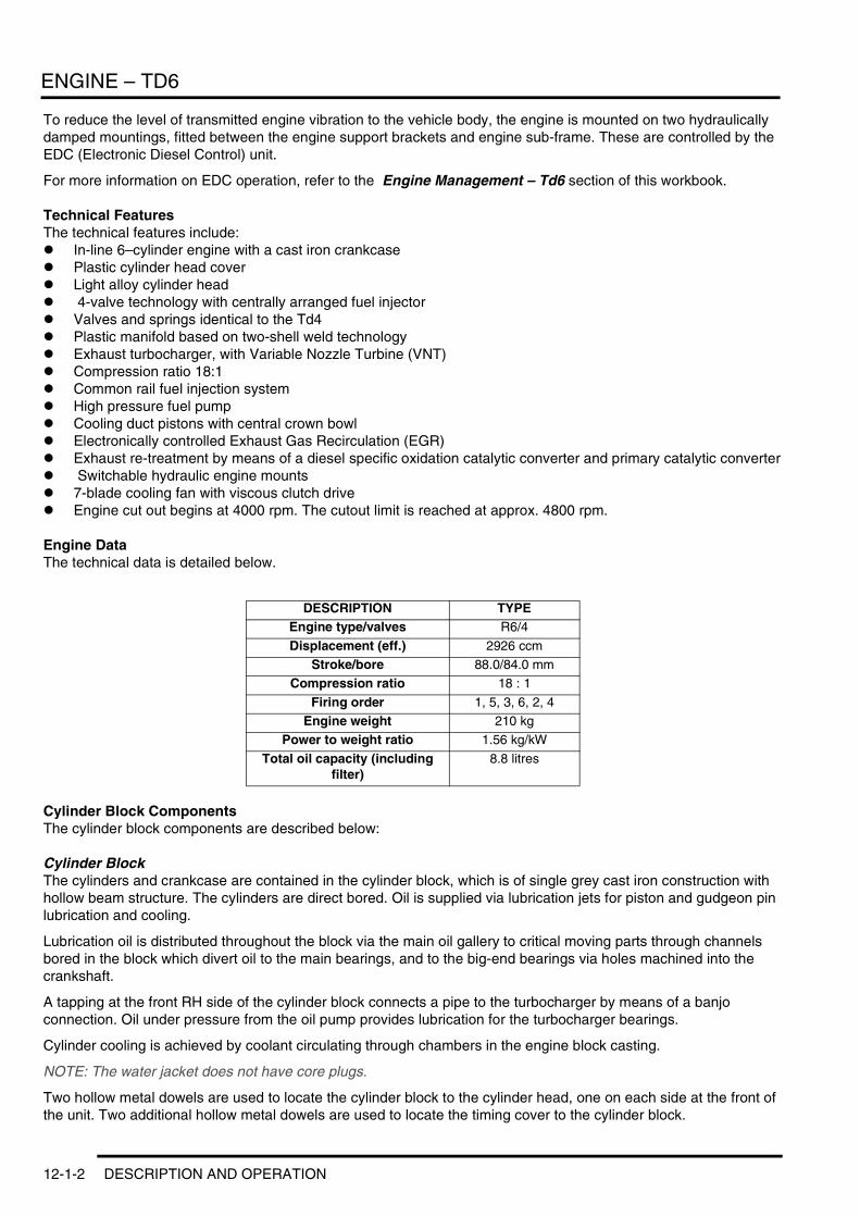
Engine DataThe technical data is detailed below.
Cylinder Block ComponentsThe cylinder block components are described below:
Cylinder BlockThe cylinders and crankcase are contained in the cylinder block, which is of single grey cast iron construction with hollow beam structure. The cylinders are direct bored. Oil is supplied via lubrication jets for piston and gudgeon pin lubrication and cooling.
Lubrication oil is distributed throughout the block via the main oil gallery to critical moving parts through channels bored in the block which divert oil to the main bearings, and to the big-end bearings via holes machined into the crankshaft.
A tapping at the front RH side of the cylinder block connects a pipe to the turbocharger by means of a banjo connection. Oil under pressure from the oil pump provides lubrication for the turbocharger bearings.
Cylinder cooling is achieved by coolant circulating through chambers in the engine block casting.
NOTE: The water jacket does not have core plugs.
Two hollow metal dowels are used to locate the cylinder block to the cylinder head, one on each side at the front of the unit. Two additional hollow metal dowels are used to locate the timing cover to the cylinder block.
DESCRIPTION TYPEEngine type/valves R6/4
Displacement (eff.) 2926 ccmStroke/bore 88.0/84.0 mm
Compression ratio 18 : 1
Firing order 1, 5, 3, 6, 2, 4Engine weight 210 kg
Power to weight ratio 1.56 kg/kW
Total oil capacity (including filter)
8.8 litres
12-1-2 DESCRIPTION AND OPERATION
ENGINE – TD6
A port is included at the rear right hand side of the cylinder block which connects to the turbocharger oil drain pipe to return lubrication oil to the sump.
A plug sealing the lubrication cross-drilling gallery is located at the front right hand side of the cylinder block. Plugs for the main lubrication gallery are included at the front and rear of the cylinder block.
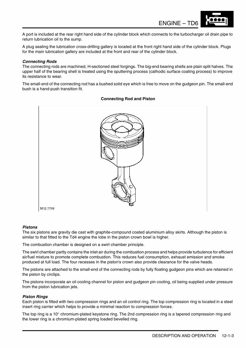
Connecting RodsThe connecting rods are machined, H-sectioned steel forgings. The big-end bearing shells are plain split halves. The upper half of the bearing shell is treated using the sputtering process (cathodic surface coating process) to improve its resistance to wear.
The small-end of the connecting rod has a bushed solid eye which is free to move on the gudgeon pin. The small-end bush is a hand-push transition fit.
Connecting Rod and Piston
PistonsThe six pistons are gravity die cast with graphite-compound coated aluminium alloy skirts. Although the piston is similar to that fitted to the Td4 engine the lobe in the piston crown bowl is higher.
The combustion chamber is designed on a swirl chamber principle.
The swirl chamber partly contains the inlet air during the combustion process and helps provide turbulence for efficient air/fuel mixture to promote complete combustion. This reduces fuel consumption, exhaust emission and smoke produced at full load. The four recesses in the piston's crown also provide clearance for the valve heads.
The pistons are attached to the small-end of the connecting rods by fully floating gudgeon pins which are retained in the piston by circlips.
The pistons incorporate an oil cooling channel for piston and gudgeon pin cooling, oil being supplied under pressure from the piston lubrication jets.
Piston RingsEach piston is fitted with two compression rings and an oil control ring. The top compression ring is located in a steel insert ring carrier which helps to provide a minimal reaction to compression forces.
The top ring is a 10° chromium-plated keystone ring. The 2nd compression ring is a tapered compression ring and the lower ring is a chromium-plated spring loaded bevelled ring.
DESCRIPTION AND OPERATION 12-1-3
ENGINE – TD6
Piston Lubrication JetsThe six lubrication jets (one for each cylinder) have a long hook-type nozzle and are fitted at the bottom right hand side of each cylinder.
The jets provide lubrication to the cylinder walls, and to the piston underskirt for cooling the pistons and lubricating the gudgeon pins and small-end bearings. The input port to each lubrication jet mates with a port provided in each mounting position, tapped at the underside of the cylinder block from a main gallery on the RH side of the block.
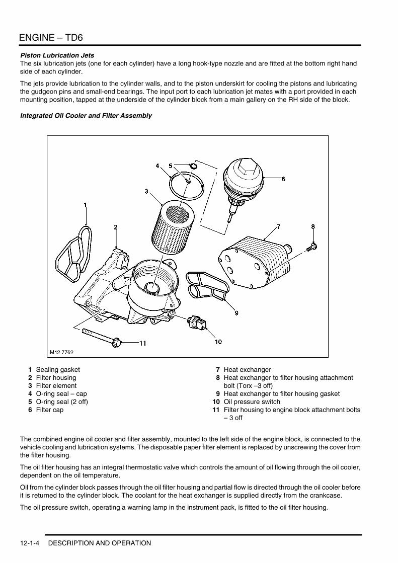
Integrated Oil Cooler and Filter Assembly
1 Sealing gasket2 Filter housing3 Filter element4 O-ring seal – cap5 O-ring seal (2 off)6 Filter cap
7 Heat exchanger8 Heat exchanger to filter housing attachment
bolt (Torx –3 off)9 Heat exchanger to filter housing gasket
10 Oil pressure switch11 Filter housing to engine block attachment bolts
– 3 off
The combined engine oil cooler and filter assembly, mounted to the left side of the engine block, is connected to the vehicle cooling and lubrication systems. The disposable paper filter element is replaced by unscrewing the cover from the filter housing.
The oil filter housing has an integral thermostatic valve which controls the amount of oil flowing through the oil cooler, dependent on the oil temperature.
Oil from the cylinder block passes through the oil filter housing and partial flow is directed through the oil cooler before it is returned to the cylinder block. The coolant for the heat exchanger is supplied directly from the crankcase.
The oil pressure switch, operating a warning lamp in the instrument pack, is fitted to the oil filter housing.
12-1-4 DESCRIPTION AND OPERATION
ENGINE – TD6
Oil Pressure Switch The oil pressure switch is located in a port in the oil filter housing. If the oil pressure drops below a given value the switch operates the warning lamp in the instrument pack
High Pressure Fuel PumpThe high pressure fuel pump supplies fuel to the fuel rail and is fixed to a flange on the front LH side of the cylinder block. The pump is a 3 radial piston type controlled by the EDC engine management system and chain driven from the crankshaft at 0.75 times engine speed.
For more information on the EDC operation, refer to the Engine Management – Td6 section of this workbook.
Crankshaft Position (CKP) SensorThe crankshaft position (CKP) sensor is mounted on the rear LH side of the cylinder block. The sensor is an inductive type which acts on a reluctor on the flywheel.
For more information on the EDC operation, refer to the Engine Management – Td6 section of this workbook.
Crankshaft and Sump ComponentsThe crankshaft and sump and oil pump components are described below:
Crankshaft
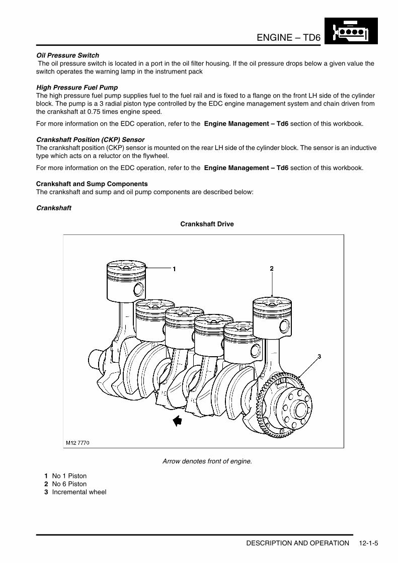
Crankshaft Drive
Arrow denotes front of engine.
1 No 1 Piston2 No 6 Piston3 Incremental wheel
DESCRIPTION AND OPERATION 12-1-5
ENGINE – TD6
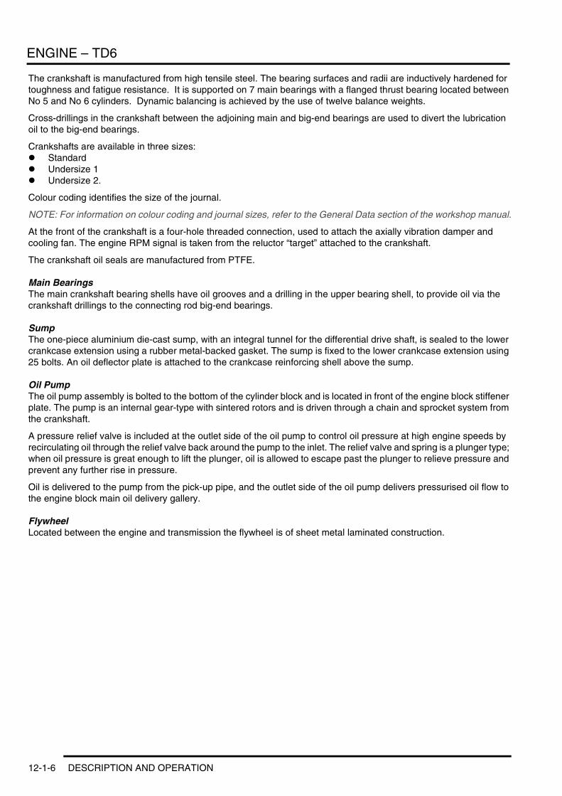
The crankshaft is manufactured from high tensile steel. The bearing surfaces and radii are inductively hardened for toughness and fatigue resistance. It is supported on 7 main bearings with a flanged thrust bearing located between No 5 and No 6 cylinders. Dynamic balancing is achieved by the use of twelve balance weights.
Cross-drillings in the crankshaft between the adjoining main and big-end bearings are used to divert the lubrication oil to the big-end bearings.
Crankshafts are available in three sizes:l Standardl Undersize 1l Undersize 2.
Colour coding identifies the size of the journal.
NOTE: For information on colour coding and journal sizes, refer to the General Data section of the workshop manual.
At the front of the crankshaft is a four-hole threaded connection, used to attach the axially vibration damper and cooling fan. The engine RPM signal is taken from the reluctor “target” attached to the crankshaft.
The crankshaft oil seals are manufactured from PTFE.
Main BearingsThe main crankshaft bearing shells have oil grooves and a drilling in the upper bearing shell, to provide oil via the crankshaft drillings to the connecting rod big-end bearings.
SumpThe one-piece aluminium die-cast sump, with an integral tunnel for the differential drive shaft, is sealed to the lower crankcase extension using a rubber metal-backed gasket. The sump is fixed to the lower crankcase extension using 25 bolts. An oil deflector plate is attached to the crankcase reinforcing shell above the sump.
Oil PumpThe oil pump assembly is bolted to the bottom of the cylinder block and is located in front of the engine block stiffener plate. The pump is an internal gear-type with sintered rotors and is driven through a chain and sprocket system from the crankshaft.
A pressure relief valve is included at the outlet side of the oil pump to control oil pressure at high engine speeds by recirculating oil through the relief valve back around the pump to the inlet. The relief valve and spring is a plunger type; when oil pressure is great enough to lift the plunger, oil is allowed to escape past the plunger to relieve pressure and prevent any further rise in pressure.
Oil is delivered to the pump from the pick-up pipe, and the outlet side of the oil pump delivers pressurised oil flow to the engine block main oil delivery gallery.
FlywheelLocated between the engine and transmission the flywheel is of sheet metal laminated construction.
12-1-6 DESCRIPTION AND OPERATION
ENGINE – TD6
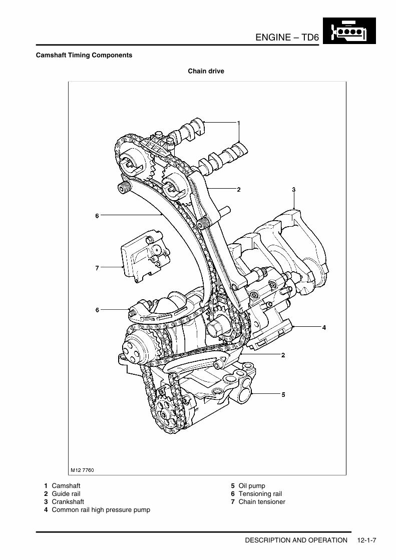
Camshaft Timing Components
Chain drive
1 Camshaft2 Guide rail3 Crankshaft4 Common rail high pressure pump
5 Oil pump6 Tensioning rail7 Chain tensioner
DESCRIPTION AND OPERATION 12-1-7
ENGINE – TD6
The camshaft timing components are described below:
Timing Case CoverThe timing chain cover is cast and machined aluminium alloy and is bolted to the cylinder block. Five bolts are used to fix the upper flange of the timing cover to the cylinder head casting, and a further four bolts secure the front of the sump to the timing cover. The bottom of the timing cover is located to the front face of the cylinder block by two metal dowels.
The front of the crankshaft passes through a hole in the timing cover, and a replaceable beaded gasket is used to seal the interface between the front of the crankshaft and the timing cover.
The ancillary components and belt pulley attachments are fitted to the front cover.
Chain DriveTwo timing chain drives are used. The timing chain between the crankshaft sprocket and the fuel injection pump sprocket is a simplex type. The timing chain is contained between one fixed and one hydraulically adjustable tensioning rail.
The chain drive from the fuel injection pump sprocket to the two camshaft sprockets is also a simplex type. The chain runs between one fixed guide rail and a hydraulically adjustable tensioning rail to minimise chain flutter. An additional plastic chain guide is located above the two camshaft sprockets.
The adjustable tensioning rails are of aluminium die casting construction with clip-fastened plastic slide linings. The fixed guide rails are moulded plastic. The tensioner rails are attached to the front of the cylinder blocks using pivot bolts which allow the tensioner rail to pivot about its axis.
The spring tensioner for both chains is provided from a single unit which contains two spring operated, hydraulically damped plungers that operate on the tensioning rails at the slack side of each of the timing chains. Pressurised oil for the adjuster is supplied through the back of the unit from an oil supply port in the front of the cylinder block. The lateral movement in the tensioner arm causes the timing chain to tension and consequently, compensation for chain flutter and timing chain wear is automatically controlled.
The timing chains are oil splash lubricated via the oil pump and chain tensioner. Oil spray is directed to the chain from several oil supply ports in the front of the cylinder block and cylinder head.
An additional chain from the crankshaft sprocket connects to the oil pump sprocket for oil pump operation.
Cylinder Head ComponentsThe cylinder head components are described below:
Cylinder HeadAlthough the Td6 is of an in-line configurationt its cylinders are arranged into 2 sets of three. The forward set consists of cylinders 1 to 3 and the rear bank consists of cylinders 4 to 6.
The cylinder head is of aluminium gravity die casting construction. The cylinder head is bolted to the cylinder block by means of M12 cylinder head bolts arranged beneath each camshaft.
NOTE: The cylinder head bolts are not accessible with the camshafts fitted.
12-1-8 DESCRIPTION AND OPERATION
ENGINE – TD6
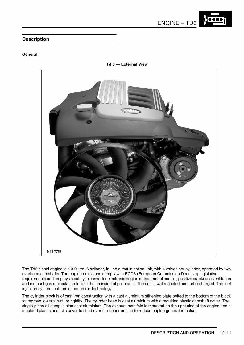
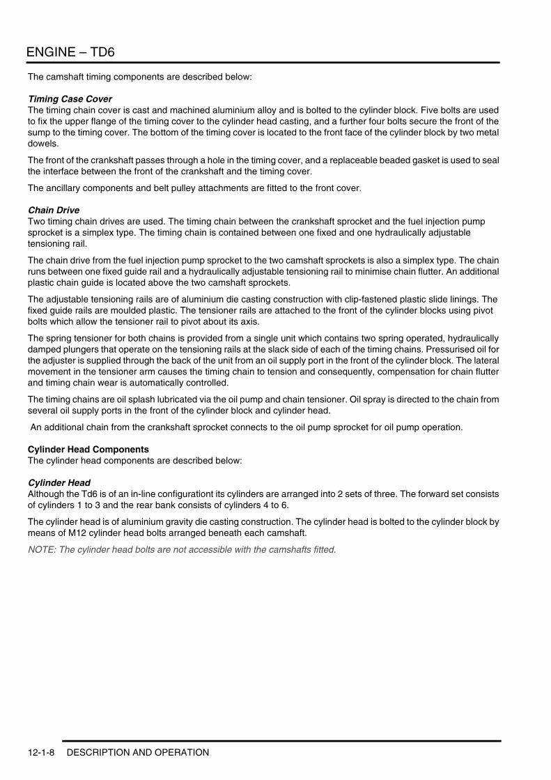
Inlet Port Configuration
1 Exhaust ports2 Exhaust valves3 Fuel injector4 Inlet swirl port5 Inlet valves6 Inlet tangential port7 Glow plug
The aluminium cylinder head houses the chain driven overhead camshafts, valve gear, fuel injectors and glow plugs. The Td6 engine has a 4–valve arrangement, similar to the Td4. There are two exhaust ports, combined in the cylinder head, a tangential inlet and a swirl inlet port. The common fuel injector rail is centrally mounted with the glow plug fitted to the inlet side.
Coolant flow enters the head from the exhaust side and exits, between No 3 and No 4 cylinder, the inlet side to the heater matrix and radiator. The Engine Coolant Temperature (ECT) sensor is screwed into an aperture at the rear LH side of the cylinder head.
For more information on the EDC operation, refer to the Engine Management – Td6 section of this workbook.
For more information on the Cooling system operation, refer to the Cooling system – Td6 section of this workbook.
Cylinder Head CoverThe plastic moulded cylinder head cover is used to seal off the oil chamber in the cylinder head. It shields oil spray from the camshaft and the chain drive gear, and acts as a housing for the valve gear.
An oil separator for the crankcase ventilation system is mounted at the top of the cover. This provides preliminary oil separation by cyclone, and fine separation using an internal yarn wrap. The separator unit also contains a pressure control valve.
The camshaft cover includes an integrated air filter housing which is de-coupled from the cylinder head to absorb and minimise the transmission of engine noise. The camshaft cover also provides a mounting for the mass air-flow (MAF) sensor.
1
6
M12 7769
3
7
2
5
4
DESCRIPTION AND OPERATION 12-1-9
ENGINE – TD6
Cylinder Head GasketThe multi-layed steel cylinder head gasket has cylinder specific water flow cross-sections for uniform coolant flow.
There are three thicknesses of gasket available, selected according to the determined piston clearance. The thickness of the gasket is identified by the number of identification holes, one hole being the thinnest and three holes being the thickest.
Vacuum PumpThe vacuum pump is located on a support bracket at the front RH side of the cylinder head and is driven from the exhaust camshaft.
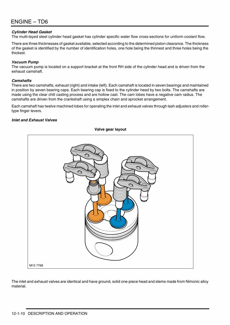
CamshaftsThere are two camshafts, exhaust (right) and intake (left). Each camshaft is located in seven bearings and maintained in position by seven bearing caps. Each bearing cap is fixed to the cylinder head by two bolts. The camshafts are made using the clear chill casting process and are hollow cast. The cam lobes have a negative cam radius. The camshafts are driven from the crankshaft using a simplex chain and sprocket arrangement.
Each camshaft has twelve machined lobes for operating the inlet and exhaust valves through lash adjusters and roller-type finger levers.
Inlet and Exhaust Valves
Valve gear layout
The inlet and exhaust valves are identical and have ground, solid one-piece head and stems made from Nimonic alloy material.
M12 7768
12-1-10 DESCRIPTION AND OPERATION
ENGINE – TD6
The valve springs are made from spring steel and are of the parallel single-coil type. The bottom end of each spring rests on the flange of a spring retainer which has an integral valve stem seal. The top end of the spring is held in place by a spring retainer which is held in position at the top end of the valve stem by split taper collets. The taper collets have grooves on the internal bore that locate to grooves ground into the upper stems of the valves.
Valve seats and valve guides are an interference fit in the cylinder head.
Hydraulic Lash Adjusters and Roller Finger RockersThe valves are operated through roller-type finger rockers and hydraulic lash adjusters, actuated by the camshaft lobes. When the camshaft lobe presses down on the top of a finger rocker, roller mechanism, the respective valve is forced down, opening the affected inlet or exhaust port. The use of this type of actuation method helps reduce friction in the valve timing mechanism.
The body of the hydraulic lash adjusters contains a plunger and two chambers for oil feed and pressurised oil. The pressurised oil is supplied to the lash adjusters via the main oil galleries in the cylinder head and through a hole in the side of the lash adjuster body. The oil passes into a feed chamber in the lash adjuster and then through to a separate pressure chamber via a one way ball valve.
Oil flow from the pressure chamber is determined by the amount of clearance between the lash adjuster outer body and the centre plunger. Oil escapes up the side of the plunger every time the lash adjuster is operated, the downward pressure on the plunger forcing a corresponding amount of oil in the lash adjuster body to be displaced. When the downward pressure from the camshaft and finger rocker is removed (i.e. after the trailing flank of the camshaft lobe has passed), oil pressure forces the lash adjuster's plunger up again. This pressure is not sufficient to effect the valve operation, but eliminates the clearance between the finger rocker and top of the valve stem.
Electronic Fuel InjectorsThere are six electronic fuel injectors (one for each cylinder), each located in the centre of a cylinder's four valves. The electronic fuel injectors are supplied with fuel from the fuel rail and deliver finely atomised fuel directly into the fuel chambers.
For more information on the Fuel injector operation, refer to the Engine Management – Td6 section of this workbook.
Ancillary Components and Belt DrivesThe ancillary components, which comprise the torsional vibration damper, alternator, A/C compressor, steering pump and water pump, are driven by the engine crankshaft via the ancillary drive belts.
The belts, which are maintenance free poly-V type belts, are automatically pre-loaded by the tensioning rollers and are routed over deflection pulleys in order to maintain sufficient adhesion about the drive wheels. This ensures slip-free drive of the ancillary components.
DESCRIPTION AND OPERATION 12-1-11
ENGINE – TD6
Belt Drive
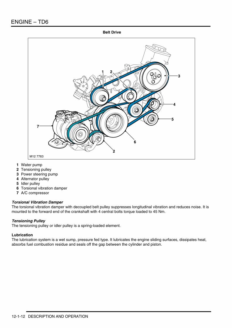
1 Water pump2 Tensioning pulley3 Power steering pump4 Alternator pulley5 Idler pulley6 Torsional vibration damper7 A/C compressor
Torsional Vibration DamperThe torsional vibration damper with decoupled belt pulley suppresses longitudinal vibration and reduces noise. It is mounted to the forward end of the crankshaft with 4 central bolts torque loaded to 45 Nm.
Tensioning PulleyThe tensioning pulley or idler pulley is a spring-loaded element.
LubricationThe lubrication system is a wet sump, pressure fed type. It lubricates the engine sliding surfaces, dissipates heat, absorbs fuel combustion residue and seals off the gap between the cylinder and piston.
M12 7763
2
6
5
213
4
7
12-1-12 DESCRIPTION AND OPERATION
ENGINE – TD6
Lubrication Circuit
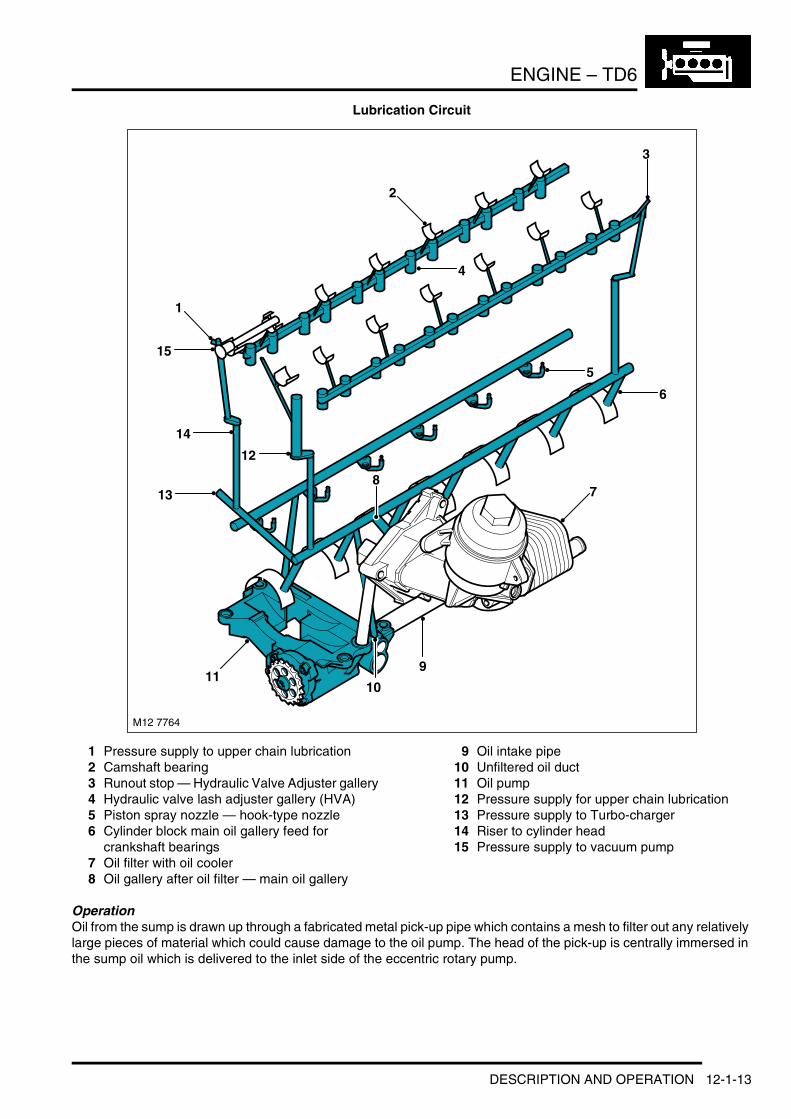
1 Pressure supply to upper chain lubrication2 Camshaft bearing3 Runout stop — Hydraulic Valve Adjuster gallery4 Hydraulic valve lash adjuster gallery (HVA)5 Piston spray nozzle — hook-type nozzle6 Cylinder block main oil gallery feed for
crankshaft bearings7 Oil filter with oil cooler8 Oil gallery after oil filter — main oil gallery
9 Oil intake pipe10 Unfiltered oil duct11 Oil pump12 Pressure supply for upper chain lubrication13 Pressure supply to Turbo-charger14 Riser to cylinder head15 Pressure supply to vacuum pump
OperationOil from the sump is drawn up through a fabricated metal pick-up pipe which contains a mesh to filter out any relatively large pieces of material which could cause damage to the oil pump. The head of the pick-up is centrally immersed in the sump oil which is delivered to the inlet side of the eccentric rotary pump.
911
87
4
5
3
2
1
15
14
M12 7764
13
10
12
6
DESCRIPTION AND OPERATION 12-1-13
ENGINE – TD6
The oil pump is driven from the crankshaft by a chain and sprocket system. Pressurised oil from the pump is passed through a port in the bottom of the cylinder block and is directed up to the oil inlet port of the oil cooler and filter housing via a port in the RH side of the cylinder block. The oil pump contains an oil pressure relief valve which opens to allow oil to be recirculated back around the pump if the oil pressure increases to a high enough level.
The inlet port of the oil cooler and filter housing has an integral non-return valve which allows flow into the filter, but prevents unfiltered oil draining back out of the filter housing when oil pressure is reduced.
The oil passes through the oil filter element and out to the oil cooler. The percentage of oil flow passed through to the oil cooler is dependent on a thermostatic by-pass valve which is integrated into the oil filter housing. An increase in oil temperature causes the by-pass valve to open and allow a greater percentage of oil flow to be directed through the oil cooler. The remainder of the oil flow from the outlet side of the filter element is directed to the outlet port of the oil filter housing where it combines with the oil flow being returned from the oil cooler before being passed back into the cylinder block.
An oil pressure switch is included in the outlet port of the oil filter housing to sense the oil pressure level before the oil flow enters the main oil gallery in the engine block. A warning lamp in the instrument pack is switched on if the oil pressure is detected to be too low.
For more information on the oil pressure warning lamp refer to the Instruments section of this workbook.
Oil entering the cylinder block main gallery passes through drillings to the crankshaft main bearings and cross drillings in the crankshaft direct oil to the big-end bearings. An additional four drillings in the cylinder block supply oil at reduced pressure to the lubrication jets for piston and cylinder cooling and gudgeon pin lubrication.
A cross channel from the LH main oil gallery crosses to the RH side of the cylinder block where there is an outlet port which provides a pressurised oil supply to the turbocharger bearings via a banjo connection and external piping.
Riser channels at the front RH side and rear LH side of the cylinder block are used to channel oil to mating ports in the cylinder head and provide a source for cylinder head lubrication and operating pressure for the lash adjusters.
Oil is fed through oil galleries at the LH and RH side of the engine and six cross channels from each gallery directs oil to the camshaft bearings. Lubrication oil fed to the lash adjusters passes up through the lash adjuster's body to the finger rockers for lubrication of the surfaces between the finger rockers and the camshaft lobes.
Tapered plugs seal the cylinder head oil galleries at the rear of the cylinder head, and an additional tapered plug is included inside the cylinder head at the front of the RH gallery.
An additional riser channel from the cylinder block LH main oil gallery is used to supply lubrication to the timing chain system through several outlet ports at the front of the cylinder block and cylinder head.
12-1-14 DESCRIPTION AND OPERATION
ENGINE – TD6
Engine Mounts
System Layout
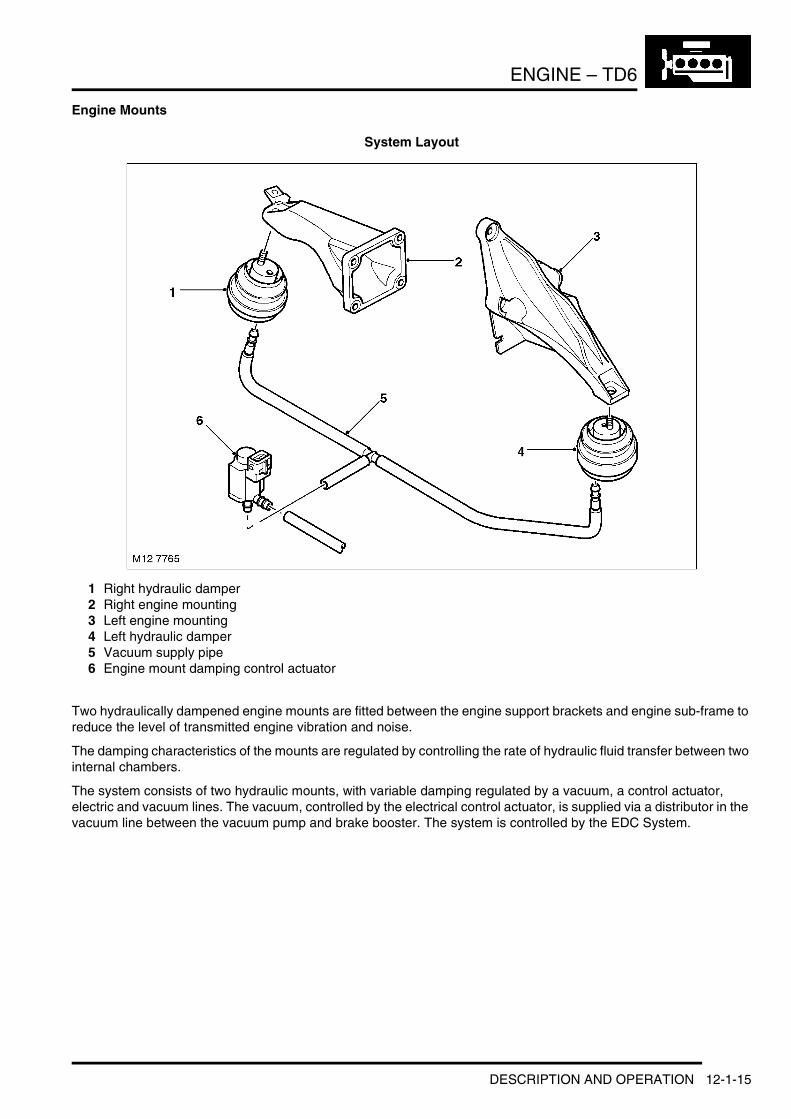
1 Right hydraulic damper2 Right engine mounting3 Left engine mounting4 Left hydraulic damper5 Vacuum supply pipe6 Engine mount damping control actuator
Two hydraulically dampened engine mounts are fitted between the engine support brackets and engine sub-frame to reduce the level of transmitted engine vibration and noise.
The damping characteristics of the mounts are regulated by controlling the rate of hydraulic fluid transfer between two internal chambers.
The system consists of two hydraulic mounts, with variable damping regulated by a vacuum, a control actuator, electric and vacuum lines. The vacuum, controlled by the electrical control actuator, is supplied via a distributor in the vacuum line between the vacuum pump and brake booster. The system is controlled by the EDC System.
DESCRIPTION AND OPERATION 12-1-15
ENGINE – TD6
Hydraulic Engine Mount
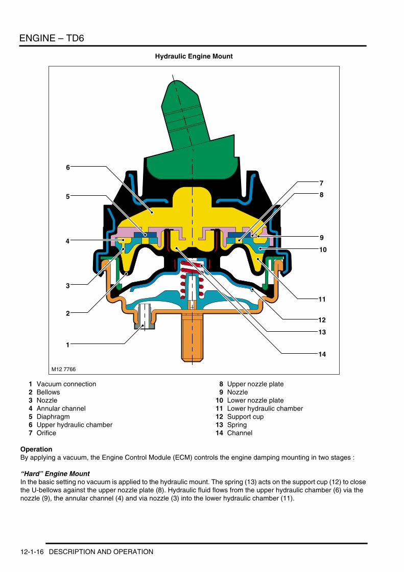
1 Vacuum connection2 Bellows3 Nozzle4 Annular channel5 Diaphragm6 Upper hydraulic chamber7 Orifice
8 Upper nozzle plate9 Nozzle
10 Lower nozzle plate11 Lower hydraulic chamber12 Support cup13 Spring14 Channel
OperationBy applying a vacuum, the Engine Control Module (ECM) controls the engine damping mounting in two stages :
“Hard” Engine MountIn the basic setting no vacuum is applied to the hydraulic mount. The spring (13) acts on the support cup (12) to close the U-bellows against the upper nozzle plate (8). Hydraulic fluid flows from the upper hydraulic chamber (6) via the nozzle (9), the annular channel (4) and via nozzle (3) into the lower hydraulic chamber (11).
M12 7766
10
3
4
5
6
8
7
9
14
12
13
11
1
2
12-1-16 DESCRIPTION AND OPERATION
ENGINE – TD6
The annular channel extends over approximately 300 degrees. Due to the length of the annular channel and the small nozzle orifice hydraulic oil flows between the upper and lower hydraulic chamber only in the case of vibrations up to the natural frequency of the engine (approximately. 10 Hz), thus producing a vibration absorber effect.
At higher frequencies, the equalisation between the hydraulic chambers is inhibited by the length of the annular channel and the small nozzle orifices. In practical terms, equalisation between the upper and lower hydraulic chamber does not take place.
Diaphragms (5) are fitted in the holes (7) of the nozzle plates in order to achieve good acoustic characteristics at high frequencies with small amplitude.
"Soft" Engine MountAt idling speed and in the speed range close to idling, the spring (13) is pulled down by applying vacuum at vacuum connection (1). The channel (14) in the centre of the upper nozzle plate now acts as a bypass between the upper and lower hydraulic chamber. This allows the hydraulic fluid to flow unrestricted between the upper and lower chambers. The increase in the fluid flow rate softens the damping action of the hydraulic mount, reducing the dynamic rigidity of the engine mount.
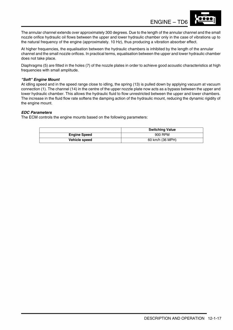
EDC ParametersThe ECM controls the engine mounts based on the following parameters:
Switching ValueEngine Speed 900 RPM
Vehicle speed 60 km/h (36 MPH)
DESCRIPTION AND OPERATION 12-1-17
ENGINE – TD6
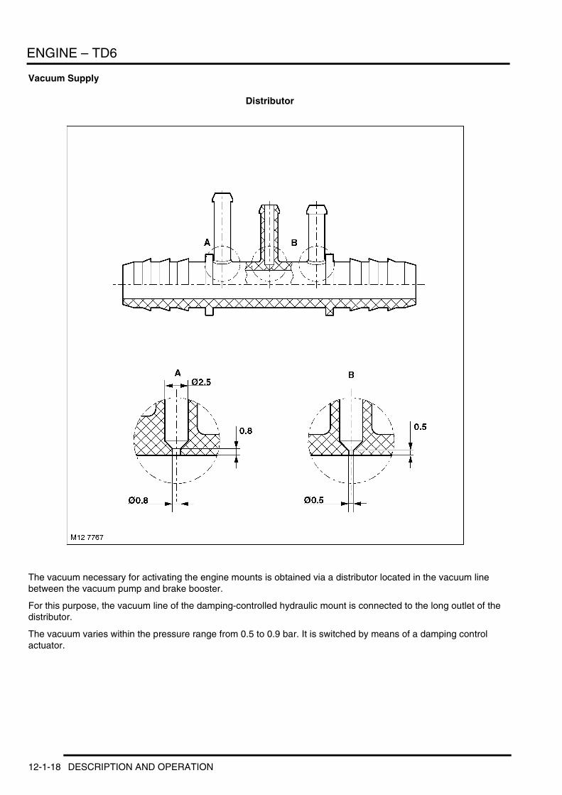
Vacuum Supply
Distributor
The vacuum necessary for activating the engine mounts is obtained via a distributor located in the vacuum line between the vacuum pump and brake booster.
For this purpose, the vacuum line of the damping-controlled hydraulic mount is connected to the long outlet of the distributor.
The vacuum varies within the pressure range from 0.5 to 0.9 bar. It is switched by means of a damping control actuator.
12-1-18 DESCRIPTION AND OPERATION