Embed Size (px)
Citation preview

RANGER-ATTM LIFTPART #: F-409RPL-AT1 (WITH ANCHOR)
PART #: F-411RPL-AT1 (WITHOUT ANCHOR)US PATENT NUMBERS: [7,249,386 B2] [D507,769 S]
350 LB. [159 kg] MAXIMUM CAPACITYMANDATORY – LEAVE THIS MANUAL WITH LIFT OWNER
9889 GARRYMORE LANEMISSOULA, MT 59808
1-888-687-3552FAX: 406-549-2602
WARNINGIMPORTANT SAFETY INSTRUCTIONS
1. READ AND FOLLOW ALL INSTRUCTIONS. LIFT SAFETY CAN ONLY BE ENSURED IF THE LIFTIS INSTALLED AND OPERATED PROPERLY – AS PER THESE INSTRUCTIONS.
2. WARNING- TO REDUCE RISK OF INJURY, DO NOT PERMIT CHILDREN TO USE THISPRODUCT UNLESS THEY ARE CLOSELY SUPERVISED AT ALL TIMES.
3. WARNING- DO NOT PERMIT CHILDREN TO PLAY ON THIS PRODUCT.4. WARNING- NEVER APPLY DIRECT WATER PRESSURE TO ELECTRONIC COMPONENTS.5. DO NOT USE THE RANGER-AT LIFT FOR WATER-DRAFTS OVER 12” (DECK TO WATERLINE).6. NEVER OPERATE THIS LIFT UNDER LOAD WITH NO WATER (DRY POOL).7. WARNING – FOR SAFETY REASONS NEVER SWIM ALONE.8. SAVE A COPY OF THESE INSTRUCTIONS.AQUA CREEK, LLC 2013 JAN 2013
- READ CAREFULLY-Check entire box and inside all packing materials for parts. Before beginning assembly, read theinstructions and identify parts using the figures and parts listed in this document. It is critical that allparts be carefully inspected by the installer prior to installation to ensure that no damage occurred intransit and that a damaged part is not used. If any damage occurred in transit, Aqua Creek Products,LLC must be notified within three days of receipt of unit. Proper installation cannot be overstressed, asan improper installation voids Aqua Creek’s warranty and may affect the safety of the user.

2
RANGER-ATTM LIFTTABLE OF CONTENTS
PAGE DESCRIPTION
3 PACKING LIST
4 ADA INSTALLATION GUIDELINES
5-6 ANCHOR INSTALLATION: CORE-DRILL RETRO-FIT
7 ANCHOR INSTALLATION: SAW-CUT RETRO-FIT
8 ANCHOR INSTALLATION: NEW CONSTRUCTION
9 RANGER-ATTM LIFT ASSEMBLY INSTRUCTIONS
10 24V BATTERY OP & INSTALL INSTRUCTIONS
11 BATTERY MAINTENANCE
12 2nd HANDSET KIT INSTALLATION (OPTIONAL)
13 RANGER-ATTM LIFT OPERATING INSTRUCTIONS
14-16 RANGER-ATTM HEADREST (OPTIONAL)
17-18 CARE FOR YOUR LIFT
19-21 TROUBLESHOOTING GUIDE
22 RANGER-ATTM PARTS LIST
23 SEAT ASSEMBLY PARTS LIST
24 WARRANTY
3
RANGER-ATTM LIFT
ITEM #7: HARDWARE BAG – PRO POOL LIFT
ITEM # QTY. DESCRIPTION PART USE / LOCATION
1 4 1/2 x 1-1/2” HEX HEAD BOLT S.S. LIFT ANCHOR BOLTS
2 4 1/2" FLAT WASHER S.S. LIFT ANCHOR BOLTS & ACTUATOR
3 1 ANTI-SEIZE CREAM PACKET
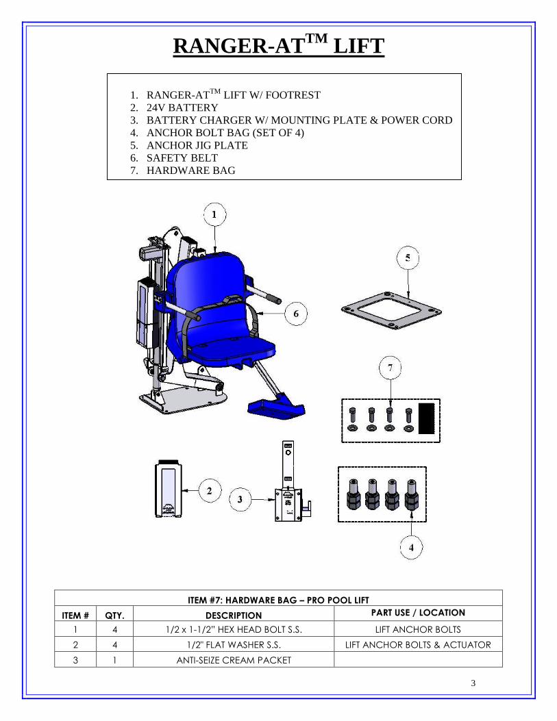
1. RANGER-ATTM LIFT W/ FOOTREST2. 24V BATTERY3. BATTERY CHARGER W/ MOUNTING PLATE & POWER CORD4. ANCHOR BOLT BAG (SET OF 4)5. ANCHOR JIG PLATE6. SAFETY BELT7. HARDWARE BAG

4
INSTALLATION: ADA GUIDELINES
ADA REQUIREMENTS:
The RANGER-ATTM LIFT is designed and manufactured to be 100% ADA compliant. But forthe installed lift to be 100% compliant the installation must meet the requirement for CLEARDECK SPACE as shown in the diagram to the left. To be compliant, install the lift at 14 inches[356mm] minimum from the pool edge, and make sure the deck has the required CLEAR DECKSPACE as shown. The setback distance can be as much as 19”, and will still be ADA compliant.
NOTE: ADA requires a deck slope of no greater than 1:48 as shown.
NOTE: The ADA requires the seat to go at least 18” into the water. To make sure the lift hasenough clearance the lift should be installed at a location with 42”-48” of depth (deck to poolfloor).
ANCHOR INSTALLATION: CORE-DRILL RETRO-FIT
5
NOTE: FOR DECKS 6” THICK OR MORE, 2500PSI MINIMUM STRENGTH
Required Materials & Tools: Core drill and 1-1/2” core drill bit Tape Measure Marking Pen suitable for writing on concrete Hammer Cold Chisel Torpedo Level High Strength 2 part construction epoxy* Black electrical tape (Optional) Masking tape
*Aqua Creek recommends either Hilti™ Brand HIT RE-500-SD or Simpson™ brand SET-XP orequivalent
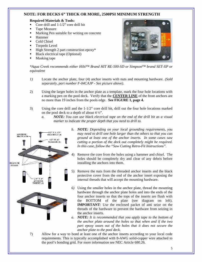
1) Locate the anchor plate, four (4) anchor inserts with nuts and mounting hardware. (Soldseparately, part number F-04CAJP - See picture above).
2) Using the larger holes in the anchor plate as a template, mark the four hole locations witha marking pen on the pool deck. Verify that the CENTER LINE of the front anchors areno more than 19 inches from the pools edge. See FIGURE 1, page 4.
3) Using the core drill and the 1-1/2” core drill bit, drill out the four hole locations markedon the pool deck to a depth of about 4 ½”.a. NOTE: You can use black electrical tape on the end of the drill bit as a visual
marker to indicate the proper depth that you need to drill to.
b. NOTE: Depending on your local grounding requirements, youmay need to drill one hole larger than the others so that you canground at least one of the anchor inserts. In some cases sawcutting a portion of the deck out completely might be required.In this case, follow the “Saw Cutting Retro-Fit Instructions”.
4) Remove the core from the holes using a hammer and chisel. Theholes should be completely dry and clear of any debris beforeinstalling the anchors into them.
5) Remove the nuts from the threaded anchor inserts and the blackprotective cover from the end of the anchor insert exposing theinternal threads that will accept the mounting hardware.
6) Using the smaller holes in the anchor plate, thread the mountinghardware through the anchor plate holes and into the ends of thefour anchor inserts so that the tops of the inserts are flush withthe BOTTOM of the plate (see diagram on left).IMPORTANT: Use the enclosed packet of anti seize on thethreads of the hardware to prevent the hardware from seizing inthe anchor inserts.
a. NOTE: It is recommended that you apply tape to the bottom ofthe anchor plate around the holes so that when and if the twopart epoxy oozes out of the holes that it does not secure theanchor plate to the pool deck.
7) Allow for a way to bond at least one of the anchor inserts according to your local coderequirements. This is typically accomplished with 8-AWG solid-copper wire attached tothe pool’s bonding grid. For more information see NEC Article 680.26.

6
8) Before putting epoxy into the holes and setting the anchor inserts, you will want to test fitthe anchor inserts in the pre-drilled holes first to make sure they line up properly. Youcan do this by picking up the anchor plate with the four (4) anchor inserts attached to theunderside and carefully place them into the four holes drilled in the deck. Using atorpedo level on the plate, verify that you can level up the anchor system. If they do notline up you may have to enlarge your holes.
9) After verifying that the anchor inserts line up with the holes properly and you can levelthe anchor assembly, remove the anchor assembly and fill each hole in the pool deck atleast half full of two part construction epoxy (not included). Aqua Creek recommendseither Hilti™ Brand HIT RE-500-SD or Simpson™ brand SET-XP or equivalent.
10) Pick up the anchor assembly with the four (4) anchor inserts attached to the undersideand carefully place them into the four holes drilled in the deck. As you place the anchorinserts that are attached to the anchor plate, wiggle the anchor system a little to make surethe epoxy gets on all sides of the anchor inserts.
11) Once the anchor inserts are placed into the holes, use a small torpedo level on the anchorplate to make sure you are level and plumb.
12) Allow the epoxy to set up according to the manufacturers recommendations and removethe hardware and the anchor plate. You can now safely mount the lift to the anchorsystem using the same hardware you used to mount the anchor inserts to the underside ofthe anchor plate. The anchor plate can be recycled or used for installing a second set ofanchors in another location.
ANCHOR INSTALLATION: SAW-CUT RETRO-FIT

7
Required Materials & Tools: Concrete saw with Diamond blade Tape Measure 4’ long Straight edge or chalk line Sledge Hammer Cold Chisel Torpedo Level Sting line Concrete & Concrete tools #4 Rebar
1) Locate the anchor plate, four (4) anchor inserts withnuts and mounting hardware). (Sold separately fromlift, part number F-04CAJP - See picture above).
2) Mark out a section of the pool deck that you areremoving using a chalk line or straight edge and amarker. You should plan on removing at least a Threefoot by three foot section.
3) Using the saw with the diamond blade, make your cutsalong the lines that you marked.
4) Using the sledge hammer, break up the concrete withinthe area that you cut and remove the pieces.
5) After you have removed the portion of the deck, verifythat your new deck will be able to be at least 6 inchesdeep.
6) Remove ONE of the nuts from each of the anchorinserts and place the anchor inserts through the largerholes in the anchor plate. Thread the nut back on theother side of the anchor insert so that the anchor plateis sandwiched between the nuts. (See diagram on left).
7) Install rebar in the open area of the deck. Tie the rebarinto the existing deck if possible.
8) Set the anchor system in place making sure that thecenter line of the front anchor inserts are no more than19 inches away from the pools edge.
9) Using the string line or a straight edge, make sure thetop of each anchor body is level and flush with theFINISHED deck surface. Each anchor body can beadjusted individually by turning the nuts with a largewrench.
10) Bond the anchor system using the bonding lug on theanchor plate. The anchor should be bonded to thepool’s bonding-grid according to your local coderequirements. (See NEC Article 680.26).
11) Pour your concrete and finish the pool deck surface.12) Once the concrete has cured, install the lift by aligning
the holes in the lifts base with the anchors installed inthe deck. Secure the lift to the deck using the stainlesssteel hardware that comes with it. (See drawingbelow)
a.NOTE: Use Anti Seize on the hardware to prevent thehardware from seizing in the anchor inserts.

8
ANCHOR INSTALLATION: NEW CONSTRUCTION
For installations where a new deck is being poured, or where a dedicated pad is being poured justfor the pool lift, the concrete must satisfy the requirements outlined on page 4. For conveniencehere are the requirements again;
YOUR POOL DECK MUST BE AT LEAST 3’-6” LONG BY 3’-6” WIDE BY 6” THICK.IT MUST BE REINFORCED WITH 5 STICKS OF #4 REBAR E-W, 2” CLEAR (MIN)FROM THE TOP AND BOTTOM OF THE FOOTING.
Obviously you may make the deck larger than this – which is almost always the case whenputting in a deck that surrounds the pool. Note that the entire deck does not need to be 6” thick,but that the area around the installed lift, 3’-6” by 3’-6”, should be 6” thick at a minimum. Therest of the deck may be thinner – 4” is typical – as long as it is 6” thick around the lift.
The new deck should be reinforced with five (5) sticks of #4 rebar with a minimum of 2”clearance top or bottom. Our minimum requirement is that the 3’-6” by 3’-6” section bereinforced accordingly, but it is good practice to extend the rebar grid over the entire deck.Commonly, the rebar grid is used for grounding/bonding also. Bonding of the lift can usually beaccomplished with a length of bare, 8 AWG solid, copper wire, connected to a piece of the rebarwith an approved fitting and then connected to the grounding lug on the anchor plate. Note; this isonly effective when the rebar grid itself has been bonded (attached to the pool’s equipotentialbonding grid with 8-AWG solid-copper wire). See NEC Article 680.26.
CHECK YOUR LOCAL ELECTRICAL CODE: BONDING REQUIREMENTS FOR POOLEQUIPMENT. ALWAYS BOND THE UNIT PER LOCAL ELECTRICAL CODES.

9
RANGER-ATTM LIFT - ASSEMBLY INSTRUCTIONS
1. Attach Seat belt to the seat as shown.
2. Install the RANGER-ATTM lift onto the four (4)anchors using the supplied 1/2 x 1-1/2” stainlesssteel hex-head bolts and 1/2" stainless steel flatwashers. Make sure all bolts are tight before usingthe lift.
3. Plug the handset cable into the large handset socketon the bottom of the control box. Be sure you pressthe cord end firmly into the socket until you are sureit is all of the way into the socket. Failure to fullypush the remote cord into the socket may result infaulty or interrupted operation.
4. Before installing the battery, place it on the charging unit and let it charge for 24hours. Make sure the orange “charge” light illuminates when the battery is beingcharged.
5. Remove the fully-charged battery from the charger and install it on top of the ControlBox. The battery will line up square with the control box, and will ‘click’ when itlocks in place properly. The lift will only operate when the battery is mountedproperly.
WHEN NOT IN USE STORE THE BATTERY ON THE CHARGER. DO NOTLEAVE THE BATTERY ON THE LIFT WHEN NOT IN USE!

10
24V BATTERY SYSTEM OPERATING ANDINSTALLATION INSTRUCTIONS
The RANGER-ATTM 24V Battery system comes with a 24v sealed rechargeable battery,wall mount charging unit (with mounting bracket), control box, and a waterproofhandheld controller. The control box is mounted to the Ranger-AT lift and has a plug-insocket for both the actuator and the handheld controller. The battery mounts directlyabove the control box with a quick-release clip.
To operate the RANGER-ATTM lift, plug in the handheld controller to the control boxand push the corresponding button to either lower or raise the unit. The lift should beable to complete approximately 10-20 full cycles before the low battery indicator tonewill sound. The low battery tone indicates that there is approximately 20% battery liferemaining. At this point, DO NOT ATTEMPT TO OPERATE THE LIFT, remove thebattery from the unit and recharge on the wall mounted charging unit.
To recharge the battery, simply grip the top of the battery and depress the clip on the backof the battery. This will unclip the battery from the control box bracket and the batterycan then be clipped into the wall mount charger. When the charger is plugged in thegreen ON light will illuminate. When the battery is correctly mounted to the charger, theorange CHARGE light will illuminate. When the battery is fully charged, theCHARGE light will GO OFF and the battery is ready for use.
WHEN THE BATTERY IS NOT BEING USED IT SHOULD BE STORED ONTHE CHARGER AND NEVER ON THE LIFT. DO NOT LEAVE THE BATTERY
ON THE LIFT WHEN THE LIFT IS NOT IN USE.
11
BATTERY MAINTENANCE
1. RECHARGE THE BATTERY AS OFTEN AS POSSIBLE. The battery power unit isa sealed lead acid battery pack. Frequent recharges will prolong the battery life andmaintain a high cold amperage capacity. THE BATTERY CAN BE STORED ON THECHARGER WHEN NOT IN USE.
2. Do NOT expose the battery to freezing temperatures.3. Do NOT expose the battery to prolonged periods of extreme heat or severe cold
temperatures.4. Do NOT expose the battery to long periods of direct sunlight. Heat will shorten your
battery life. Optimum operating temperature is below 20 degrees Celsius (68 degrees F.)5. Never drop or bump the battery pack. This may result in loose or damaged internal
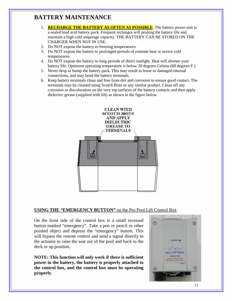
connections, and may bend the battery terminals.6. Keep battery terminals clean and free from dirt and corrosion to ensure good contact. The
terminals may be cleaned using Scotch Brite or any similar product. Clean off anycorrosion or discoloration on the very top surfaces of the battery contacts and then applydielectric grease (supplied with lift) as shown in the figure below.
USING THE “EMERGENCY BUTTON” on the Pro Pool Lift Control Box
On the front side of the control box is a small recessedbutton marked “emergency”. Take a pen or pencil or otherpointed object and depress the “emergency” button. Thiswill bypass the remote control and send a signal directly tothe actuator to raise the seat out of the pool and back to thedeck or up position.
NOTE: This function will only work if there is sufficientpower in the battery, the battery is properly attached tothe control box, and the control box must be operatingproperly.

12
2ND HANDSET-KIT INSTALLATION (OPTIONAL):
For applications that require a 2nd handset-remote, for instance in public facilities, theRANGER-AT has an optional 2nd handset kit available. The kit consists of a 2nd 2-buttonhandset-remote, a bracket for holding the remote at the proper, fixed location and a y-adapter cable for connecting the two handsets to the control box.
To install the device remove the back-front ½” anchor-bolt and install the bracket andhandset as shown in the figure below. The bracket makes it possible to use the 2nd
handset from either the pool or the deck, so that a handset is always available.
13
RANGER-ATTM LIFT OPERATING INSTRUCTIONS:
NOTE: CHECK ALL NUTS & BOLTS FOR TIGHTNESS AND FORWORN PARTS BEFORE EACH USE. NEVER OPERATE THE LIFTWITH THE ARMRESTS FLIPPED UP.
The RANGER-ATTM lift should always be in the full up or deck position before a userattempts to transfer into the chair. Before attempting to transfer into the chair, check tomake sure the lift is operating by making a short test run: move the chair at least part wayin and out of the pool.
As you are standing in front of the chair, facing the chair, the armrest on either side willflip up to allow for easier lateral transfers. Transfer into the chair and then lower the flip-up armrest back into its normal position. Secure the adjustable lap belt around the waistso that the belt is snug, but not uncomfortably tight.
You are now seated comfortably in the RANGER-ATTM lift, and ready to move into thepool or spa. Before you begin the operating cycle, take a visual check of the deck areaand pool area to make sure the operating path of the lift is clear.
It is not necessary to lower the lift all the way to the bottom of the lift’s stroke. You maystop the lift at any time in the downward cycle once the chair is under water and it iscomfortable for you to exit the chair into the water.
This is NOT true however, when returning to the deck during the up cycle. The liftshould always be cycled completely to the up or deck position before attempting to exitthe chair on the deck.
To lower the lift into the pool, simply apply pressure on the down arrow button on theremote control handset and the chair will start to move towards the pool. NOTE: forsafety reasons, it is necessary to maintain continuous pressure on the control button. Ifyou take your finger off of the control button the lift will stop.
When you are sufficiently submerged into the water to allow for an easy exit from thechair, you may stop the lift cycle by releasing pressure on the down arrow button on theremote control handset. Now release the lap belt by grasping the end of the belt that isprotruding above the lap belt and tugging gently. You may now flip up the footrest tocreate more room in front of the chair for you to exit. Exit the chair by sliding straightforward until you are clear of the seat and the footrest.
When you are ready to return to the lift seat and exit the pool or spa, make sure that the chair is lowered(submerged) sufficiently to allow you to easily slide into the chair. You should not attempt to “lift” or raiseyourself into the chair. Once you are reseated into the chair, you may lower the footrest to it normaloperating position and place your feet on the footrest. Next, re-secure the adjustable lap belt snugly aroundyour waist. To raise the chair out of the pool, simply press on the up arrow button on the remote controlhandset and apply continuous pressure until the lift chair comes to a rest on the deck in the full up position.You may now release the lap belt and exit the chair.

14
THE (OPTIONAL) HEADREST ASSEMBLY
The HEADREST ASSEMBLY attaches directly to the chair assembly, and is adjustablefor optimum comfort. The components of the HEADREST ASSEMBLY are shownbelow, along with the chair to show how it attaches. The wing-nuts allow for quickadjustment without having to remove the assembly from the chair. The headrest pad isalso removable for cleaning. Look over the diagram below to familiarize yourself withthe components before installing and using the HEADREST ASSEMBLY.

15
INSTALLING THE HEADREST PAD
The ADJUST BRACKET must be removed from the assembly to install or remove theHEADREST PAD. When installing the pad; thread the bracket through the top loops firstand then press the flaps together (hooks & loops fastener) to complete the installation. Toremove the pad, reverse this procedure.

16
INSTALLING THE HEADREST ASSEMBLY
1] If the HEADREST PAD has notyet been installed install it first.The pad height may be adjustednow, or after the assembly hasbeen attached to the chair.Assemble fully as shown in thediagram to the right.
2] Slide the SUPPORT BRACKETinto the slots on the top of thechair.
The INTEGRATED HEADRESTASSEMBLY is now ready toadjust and use.
NOTE: The INTEGRATED HEADREST ASSEMBLY will work on all 2nd generation18” wide Aqua Creek Products’ chairs*. The 18” chair comes standard on all Aqua CreekProducts’ ScoutTM, RangerTM, Pro PoolTM and PatriotTM pool lifts.
*(The 2nd generation 18” wide chair has the slots for the INTEGRATED HEADREST,where the 1st generation 18” wide chair does not).

17
CARE OF YOUR LIFTRoutine cleaning is an absolute necessity to ensure the integrity of the lift. Note that theAqua Creek Pool Lift should not be stored in a pump room or in a storage room wherepool chemicals are kept. Storing the lift near pool chemicals may cause rusting and otherdamage to occur. Your Aqua Creek stainless steel lift is powder coated to protect thestainless steel from rusting. Most rusting will occur at weld points, crevices, undergaskets, rivets or bolt heads.
The choice of a proper cleaning product is up to the consumer and there are many tochoose from. Depending on the type of cleaning and the degree of contamination(rusting), some products are better than others. For routine cleaning the products mostrecommended are gentle soaps or detergents or dilute mixtures of ammonia. Forstubborn spots and stains try using soft scrub with some brisk rubbing.
DO NOT USE POOL WATER TO CLEAN USE ONLY FRESHWATER
If the lift is used DAILY make sure to wash the lift at the end of the day. Wash the liftoff using a mild soap and a soft cloth. Make sure to pay special attention to weld pointsand crevices. Do not use a bristled brush or steel wool to clean the lift. Check that thelift is working properly and then place the battery on the charger. It is recommended thatthe battery be charged after every day of use.
If the lift is used WEEKLY follow the same steps as above. Also be sure to check all ofthe contact points (terminals) for damage or corrosion. If you notice corrosion gentlyclean the terminals. To clean corrosion from the terminals use a q-tip and some rubbingalcohol. If the corrosion is particularly stubborn try using a 3M scotch brite pad, but becareful not to damage the terminals. Apply dielectric grease to the terminals aftercleaning them. This will help to prevent further corrosion. Do not leave the battery on thelift. Always store the battery on the charger whenever the lift is not being used.
SAFETY & MAINTENANCE INSTRUCTIONSDo not play on or around this lift
1. Check the RANGER-ATTM lift before each use to assure there are no worn partsand that all hardware is properly tightened. If there are any worn parts, replacethem BEFORE using the Pro Pool LiftTM. You can call our customer service at 1-888-687-3552 to order any parts.
2. Aqua Creek Products, LLC lifts shall be grounded per local codes.3. At least ONCE A WEEK, the RANGER-ATTM lift must be cleaned with fresh
water. Do not spray the RANGER-ATTM 24v battery unit directly with anypressure. Wipe all surfaces clean with a damp, non-abrasive cloth. Whencleaning the RANGER-ATTM, use non-abrasive soap and water. Avoid harshchemicals and disinfectants.
4. Always read the label instructions on any cleaner carefully before applying it to asurface.
5. The WARNING & INTENDED USE labels on the RANGER-ATTM need to bemaintained in readable fashion. If they become unreadable or faded, pleasereplace the label immediately. Replacement labels are available from AQUACREEK PRODUCTS LLC. 1-888-687-3552.

18
If the lift is used MONTHLY follow the same steps as above. Also check the nuts andbolts to make sure they are securely fastened (this is always a good idea, no matter howoften or infrequently the lift is used). Also make sure to store the battery on the chargerand not on the lift. Leaving the battery on the lift for extended periods will significantlyshorten the battery’s lifespan.
If the lift is being STORED for an extended period of time follow all of the steps above.Check for rusting at all crevice and weld points. If you notice rusting spray some WD-40on the affected area and take a 3M scotch brite pad and rub briskly. Afterwards be sureto wash and rinse the lift again with soap and water. When storing the lift make sure it isin a dry area and covered. DO NOT STORE in or around pool chemicals.

19
TROUBLESHOOTING GUIDE
Before troubleshooting make sure the battery is fully charged.
If the lift doesn’t move when the handset button is pressed:When you can’t get the lift to move check the following things:
1. Make sure the battery is fully charged:A. Before charging the battery first make sure the green light on the front
of the charger is illuminated (this means that the charger is on). Thencheck to make sure the silver contact points on the battery and chargerare not damaged or corroded, and that they are clean. Then place thebattery on the charger and look for the orange charge light toilluminate on the front of the charger. When the orange light goes offthe battery is fully charged.
B. When the battery is correctly installed on the charger or control boxyou should hear a “click” indicating the battery is properly seated onthe unit. Also note that when the battery is properly seated thereshould not be any gaps between the battery and the controlbox/charger.
The top green light will alwaysbe illuminated indicating that ithas power. When charging thebattery the bottom orange lightwill illuminate, until fullycharged.
Not attached properly. Notethe white bracket is in front ofsilver clip, which will not allowfor an electrical connection.
Properly Attached.Note that the white bracket isbehind the silver clip. Not allowingmovement.

20
If the battery is fully charged and the lift is not moving then:2. Check all cords:
A. Check that the cords are properly plugged in. Start by unplugging theremote and the actuator cord from the control box. Once these cordsare removed check the ends for corrosion or damage. Plug the remotecord back in by lining up the raised tab on the plug to the grooved lineon the control box outlet. Note that these cords require some force toplug them in fully. You will know they a correctly inserted when youhere a “popping sound”. The cords will be recessed into the outlet. Ifthey are flush with the outside of the outlet they are not plugged infully and the lift will not function. Make sure you do this for bothcords.
If you have checked all the cords and the lift still doesn’t move:3. Check the contact points:
A. After you have fully charged the battery and checked the cords tomake sure they are properly plugged in, check to make sure the contactpoints are not corroded or bent. If the contact points are corroded takesome rubbing alcohol and a q-tip and clean off the points. Aftercleaning the contact points it is recommended to put some dielectricgrease on the contact points (terminals) to help ensure good electricalcontact and prevent corrosion. Then reinstall the battery on top of thecontrol box. Make sure you hear a “click”, which indicates that thebattery is correctly seated. The lift will not work if the battery is notseated correctly.
NOT inserted fully. Fully inserted.
Silver tabs are the contact(terminal) points.

21
If the lift stops moving over the water and is stuck:4. Then try pushing the emergency button:
it into the emergency button on the front of the control box to retract thelift. Note the lift will not retract if the battery is not fully charged or if thecontrol box is not working. The emergency button only overrides theremote in case it has gone bad. If this does not retract the lift then chancesare the remote is fine and you either have a problem with the battery, thecontrol box, or the cords are damaged or not plugged in properly.
Use a pen or pencil tipto push in the smallblack circle located nextto the word emergency,on the front of thecontrol box.

22
ITEM NO. QTY PART NUMBER DESCRIPTION
1 1 PPB-100-10 PRO POOL-AT BASE ASSEMBLY
2 1 PPF-200-10 PRO-POOL-AT FRAME ASSEMBLY
3 1 A-2012ARM-R1 PRO POOL CHAIR-ARM ASSEMBLY
4 1 A-2102SRS PRO POOL SEAT SUPPORT
5 1 L-2014FBL-PAT-R2 PRO POOL-AT CONTROL ARM
6 1 A-9890RAAF-AT RANGER-AT ACTUATOR ASSY
7 1 SA-0904CA-A 18" CHAIR ASSEMBLY
8 1 SA-0904FRA FOOTREST ASSEMBLY
9 2 BOLT, 1/4 x 3/8 HWH, SS 1/4"-20 X 3/8" HEX WASHER HEAD, SS
10 1 BOLT, 5/16 x 4 HCS 5/16"-18 X 4" HEX BOLT, SS
11 3 FLAT WASHER, 5/16 SS 5/16" FLAT WASHER, SS
12 2 NYLOCK, 5/16 SS 5/16"-18 NYLOCK NUT, SS
13 1 BOLT, 3/8 x 1 3/4 SHOULDER 3/8" X 1-3/4" SHOULDER BOLT, SS
14 2 FLAT WASHER, 1/2 SS 1/2" FLAT WASHER, SS
15 2 NYLOCK, 1/2 SS 1/2"-13 NYLOCK NUT, SS
16 2 BOLT, 5/8 x 1 1/4 HCS 5/8"-11 X 1-1/4" HEX BOLT, SS
17 1 BOLT, 5/8 x 6 HCS 5/8"-11 X 6" HEX BOLT, CUSTOM
18 2 FLAT WASHER, 5/8 SS 5/8" FLAT WASHER, SS
19 1 NYLOCK, 5/8 SS 5/8"-11 NYLOCK NUT, SS
20 2 NYLOCK, 5/8 JAM 5/8"-11 HEX-JAM NYLOCK, SS
21 1 NYLOCK, 3/4 SS 3/4"-10 NYLOCK NUT, SS
22 2 TT-1001-1 7/8" X 1/2" X 1/8" THST WSR, BZ
23 2 MACH-BUSHING, 7/8 X 5/8 X 1/4 7/8" X 5/8" 1/4" CUSTOM BUSHING
24 1 TT-1205-1 1-1/4 X 3/4 X 1/8 THST WSR, BZ
25 2 FL-50-3 5/8" X 1/2" X 3/8" FLNG BRNG, BZ
26 2 FL-64-6 7/8" X 5/8" X 3/4" FLNG BRNG, BZ
27 1 MACH-BUSHING, 7/8 X 3/4 X 1/4 7/8" X 3/4" X 1/4" CUSTOM BUSHING
28 2 FL-75-6 7/8" X 3/4" X 3/4" FLNG BRNG, BZ
29 3 SQR-1-14-20 1" SQUARE PLASTIC CAP, BLK
30 3 SQR-2-10-14 2" SQUARE PLASTIC CAP, BLK
31 2 RER-50X100MM 2" X 4" RECT. PLASTIC CAP, BLK
RANGER-ATTM LIFT: PARTS LIST

23
ITEM NO. QTY. PART NUMBER DESCRIPTION
1 1 P-901 CHAIR, BLUE ROTOMOLDED (18" WIDE)
2 2 P-2100FLA-A ARMREST TUBE
3 1 P-1208HSB HANDSET BRACKET, HDPE
4 2 RUBBER HAND GRIPS RUBBER HAND GRIPS, BLACK
5 2 SCREW, #12 X 3/4 FHSMS #12 X 3/4" FLAT-HD SHEET-METAL SCR SS
6 4 FLAT WASHER, 1/4 SS 1/4" FLAT WASHER, 316 SS
7 2 BOLT, 1/4 X 3 1/4 BHSCS 1/4"-20 X 3-1/4" BUTTON-HD CS, SS
8 2 NYLOCK, 1/4 SS 1/4"-20 NYLOCK NUT, SS
9 1 COTTER PIN, 1/4 X 3 1/4 1/4" X 3-1/4" QUICK-PULL PIN FOR FOOTREST
10 1 LANYARD SS LANYARD FOR FOOTREST PIN
11 1 SCREW, #10 X 3/4 PHSMS #10 X 3/4" PAN-HEAD SHEET-METAL SCR, SS
12 1 F-38SB SEAT BELT, 2" BLACK W/VELCRO FOR PP
13 2 RUBBER BUMPER 3/8 3/8" RUBBER BUMBER, BLACK
14 2 SCREW, #6 X 1/2 PHSMS #6 X 1/2" PAN-HD SHEET-METAL SCR, SS
ITEM NO. QTY. PART NUMBER DESCRIPTION
1 1 A-9890RAAF-AT RANGER-AT ACTUATOR FRAME
2 1 340461-00 600mm LINEAR ACTUATOR
3 1 CBJ2001NA001381 1-CHANNEL CONTROL BOX
4 1 MBJ2-01 MOUNTING BRACKET, CB/BATTERY
5 1 M5 X10 LPCS M5 X 10mm LOW-PRO CAP SCREW
6 1 BAJ100000291 24V BATTERY W/ACP LOGO
7 2 SQR-1-14-20 1" SQUARE PLASTIC CAP, BLK
8 1 BOLT, 3/8 X 1 1/4 SHOULDER 3/8" X 1-1/4" SHOULDER BOLT, SS
9 1 FLAT WASHER, 5/16 SS 5/16" FLAT WASHER, SS
10 1 NYLOCK, 5/16 SS 5/16"-18 NYLOCK NUT, SS
11 2 HOSE CLAMP, 1 3/4. SS 1-3/4" HOSE CLAMP, SS
12 1 FLAT WASHER, #10 #10 FLAT WASHER, SS
SEAT ASSEMBLY: PARTS LIST
ACTUATOR ASSEMBLY: PARTS LIST

24
Aqua Creek Products, LLC Limited Warranty:RANGER-ATTM Pool Lift
Aqua Creek Products Ranger lifts have a Limited 2-Year Warranty on the frames, not including the powder coatfinish.Aqua Creek Products, LLC (a.k.a. Aqua Creek) also warrants to the original end user that all non-frame componentsmanufactured by Aqua Creek, when properly installed in accordance with assembly and installation instructions, andproperly used and maintained, shall be free from defects in material and workmanship for a period of two (2) yearsfrom the date of original purchase, provided that Aqua Creek receives prompt notice in writing of any defect orfailure and satisfactory proof thereof.
This warranty specifically excludes reimbursement for labor to remove, repair, or install the product and any returnfreight charges.These warranties do not cover any damages due to accident, misuse, abuse, negligence or failure to properly maintainany products, or normal wear and tear from day to day operations. In the event that any products are altered, repaired, orimproperly installed or improperly used by anyone without the prior written approval by Aqua Creek, all warranties arevoid. IMPORTANT: AMOUNT OF WEIGHT PLACED ON LIFT SHALL NOT EXCEED THE RATED LIFTINGCAPACITY OF 350 POUNDS [159 kg] FOR THE RANGER-ATTM POOL LIFT.
To initiate a warranty claim, the owner of an Aqua Creek product must provide the place of purchase, in writing,with a full description of the product, its serial number, the dates of purchase and installation, and the exact nature ofthe defect. Within thirty (30) days after receipt of a written warranty claim by Aqua Creek, and barring anyunforeseen delays, the place of purchase will be notified of Aqua Creek’s decision regarding the claim.
If requested by Aqua Creek, any defective product must be returned, freight prepaid, to Aqua Creek’s designatedfactory location or duly appointed distributor for inspection and/or repair. Aqua Creek will, at its option, repair orreplace the failed or defective item, and deliver the repaired product or replacement to the buyer of the product,freight prepaid to the destination provided for in the original order. Products returned to Aqua Creek for which AquaCreek provides replacement under this limited warranty shall become the property of Aqua Creek.
A new warranty period shall NOT be established for the repaired or replaced products. Such products shall remainunder warranty only for the remainder of the original warranty period on the original products purchased.
This written limited warranty constitutes the final, complete and exclusive statement of warranty terms. No personor organization is authorized to make any other specific or implied warranties or representations on behalf of AquaCreek.
THE WARRANTIES SET FORTH HEREIN ARE IN LIEU OF ALL OTHER WARRANTIES, EXPRESSED OR IMPLIED, WHICH AREHEREBY DISCLAIMED AND EXCLUDED, INCLUDING WITHOUT LIMITATION ANY WARRANTY OF MERCHANTABILITY ORFITNESS FOR A PARTICULAR PURPOSE OR USE.
THE SOLE AND EXCLUSIVE REMEDIES FOR BREACH OF ANY AND ALL WARRANTIES WITH RESPECT TO THE PRODUCTSSHALL BE LIMITED TO REPAIR OR REPLACEMENT AT AQUA CREEK’S DESIGNATED FACTORY LOCATION, OR DULYAPPOINTED DISTRIBUTOR, OR IN PLACE AT AQUA CREEK’S OPTION. IN NO EVENT SHALL AQUA CREEK’S LIABILITYEXCEED THE ENTIRE AMOUNT PAID TO AQUA CREEK BY THE ORIGINAL PURCHASER FOR THE FAILED OR DEFECTIVEPRODUCT.
IN NO EVENT SHALL AQUA CREEK PRODUCTS, LLC BE LIABLE FOR ANY INCIDENTAL, CONSEQUENTIAL, SPECIAL,INDIRECT, PUNITIVE OR EXEMPLARY DAMAGES OR LOST PROFITS FROM ANY BREACH OF THIS LIMITED WARRANTY OROTHERWISE.
THIS WARRANTY GIVES YOU SPECIFIC LEGAL RIGHTS AND YOU MAY ALSO HAVE OTHER RIGHTS, WHICH MAY VARYFROM STATE TO STATE.
SOME STATES DO NOT ALLOW THE EXCLUSION OR LIMITATION OF INCIDENTAL, SPECIAL OR CONSEQUENTIAL DAMAGES,SO SOME OF THE ABOVE LIMITATIONS OR EXCLUSIONS MAY NOT APPLY TO YOU.
Aqua Creek Products9889 Garrymore LaneMissoula, MT 59808