Embed Size (px)
Citation preview

2
DEPARTMENT OF ELECTRICAL AND ELECTRONICS ENGINEERING
ME8792 POWER PLANT ENGINEERING
UNIT-I COAL BASED THERMAL POWER PLANTS
Rankine cycle-improvisations, Layout of modern coal power plant, Super critical boiler
FBC boilers, Turbines, condensers, Steam and heat rate, subsystems of thermal power plants-
Fuel and ash handling, draught system, Feed water treatment, Binary cycles and cogeneration
systems.
RANKINE CYCLE-IMPROVISATIONS
Fig.1 The arrangement of the components used for steam power plant working on rankine cycle.
The line diagram of the power plant working on Rankine cycle is shown in Fig 1. The
rankine cycle used for steam power plant is shown in Fig. 2 and Fig 3 on P-V and T-S diagrams.
The different processes of the Rankine cycle are described below:
(1) The point „d‟ represents the water at condenser pressure P2 and corresponding
saturation temperature T2. The process „de‟ represents the adiabatic compression of
water by the pump from pressure P2 (condenser pressure) to pressure P1 (boiler
pressure). There is slight rise in temperature of water during the compression process
„de‟.
(2) During the processes „ea‟ and „ab‟, heat is supplied by the boiler to the water to
convert into steam. The process „ea‟ represents the supply of heat at constant

3
pressure till the saturation temperature of water is reached corresponding to boiler
pressure P1. The point‟s e and a are same on PV diagram as increase in volume of
water during this heating process is negligible. The process „ab‟ represents the
addition of heat to the water at constant pressure till the water completely converted
into steam. The final condition of steam „b‟ may be wet, dry saturated or superheated
depending upon the quantity of heat supplied by the boiler.
Fig 2.Rankine cycle On Fig 3.Rankine cycle on T-S diagram
P-V diagram
(3) The process „bc‟ represents the isentropic expansion of steam in the prime mover as
shown in Fig.3. During this expansion, external work is developed and the pressure
of steam falls from P1 and P2 and its temperature will be T2.
(4) The process „cd‟ represents the condensation of steam coming out from the prime
mover in the condenser. During the condensation of steam, the pressure is constant
and there is only change of phase from steam to water as the latent heat of steam
(x2hfg2) is carried by circulating water in the condenser.
(5) Again the process „de‟ represents the adiabatic compression of water by the pump
from the pressure P2 to P1 and the cycle is repeated
Fig.4 Rankine cycle neglecting pump

4
5
LAYOUT OF MODERN COAL POWER PLANT(Anna university Nov/Dec 10,11,12)
Introduction
The development of power in any country depends upon the available resources in that
country. The hydel power totally depends upon the natural sites available and hydrological cycle
in that country. New sites cannot be humanly created for hydel power plants.
The development of nuclear power in a country requires advanced technological
developments and fuel resources. This source of power generation is not much desirable for the
developing countries as it is dependent on high technology and they are highly capital based
systems.
Many times, hydel power suffers if draught comes even once during a decade and the
complete progress of the nation stops. The calamity of rain draught on power industry has been
experienced by many states of this country.
To overcome this difficulty, it is absolutely necessary to develop thermal plants in the
country which are very much suitable for base load plants.
The general layout of the thermal power plant consists of mainly four circuits as shown in
Fig.5 the four main circuits are:
1. Coal and ash circuit
2. Air and gas circuit
3. Feed water and steam flow circuit
4. Cooling water circuit.
1. Coal and ash circuit
In this circuit, the coal from the storage is fed to the boiler through coal handling
equipment for the generation of steam. Ash produced due to the combustion of coal is
removed to ash storage through ash-handling system.
2. Air and Gas circuit
Air is supplied to the combustion chamber of the boiler either through F.D or I.D
or by using both. The dust from the air is removed before supplying to the combustion
chamber.
The exhaust gases carrying sufficient quantity of heat and ash are passed through
the air-heater where the exhaust heat of the gases is given to the air and then it is passed
through the dust collectors where most of the dust is removed before exhausting the gases
to the atmosphere through chimney.
3. Feed water and Steam circuit
The steam generated in the boiler is fed to the steam prime mover to develop the
power. The steam coming out of prime mover is condensed in the condenser and then
fed to the boiler with the help of the pump.

6
The condensate is heated in the feed-heaters using the steam tapped from different
points of the turbine. The feed heaters may be of mixed type or indirect heating type.
Some of the steam and water is lost passing through different components of the
system; therefore, feed water is supplied from external source to compensate this loss.
The feed water supplied from external sourced is passed through the purifying plant to
reduce the dissolved salts to an acceptable level. The purification is necessary to avoid
the scaling of the boiler tubes.
4. Cooling water circuit
The quantity of cooling water required to condense the steam is considerably
large and it is taken either from lake, river or sea. The cooling water is taken from the
upper side of the river, it is passed through the condenser and heated water is discharged
to the lower side of the river. Such system of cooling water supply is possible if adequate
cooling water is available throughout the year. This system is known as open system.
When the adequate water is not available, them the water coming out from the
condenser is cooled either in cooling pond or cooling tower. The cooling is effected by
partly evaporating the water. This evaporative loss is nearly 2 to 5% of the cooling water
circulated in the system.
To compensate the evaporative loss, the water from the river is continuously
supplied. When the cooling water coming out of the condenser is cooled again and
supplied to the condenser is cooled again and supplied to the condenser then the system is
known as closed system.
When the water coming out from the condenser is discharged to river downward
side directly, the system is known as open system. Open system is economical than
closed system provided adequate water is available throughout the year.
Working of the thermal power
Steam is generated in the boiler of thermal power plant using the heat of the fuel burned
in the combustion chamber. The steam generated is passed through steam turbine where part of
its thermal energy is converted into mechanical energy which is further used for generating
electric power.
Merits:
(i) Higher efficiency
(ii) Lower cost
(iii) Ability to burn coal especially of high ash content, and inferior coals.
(iv) Reduced environmental impact in terms of air pollution
(v) Reduced water requirement
(vi) Higher reliability and availability

7
Demerits:
(i) There are more chances of explosion as coal burns like a gas
(ii) Coal transportation is quite complicated.
SUPER CRITICAL BOILERS
The increasing fuel costs with decreasing fuel quantity have constantly persuaded power
engineers to search for more economical methods of power generation. The most recent method
to produce economical thermal power is by the use of super-critical steam cycle.
Between the working ranges of 125 bar and 510°C to 300 bar and 600°C, large numbers
of steam generating units are designed which are basically characterized as sub-critical and
super-critical. Usually a sub-critical boiler consists of three distinct sections as preheater
(economizer), evaporator and superheater and in case of super-critical boiler, the only preheated
and superheaters are required.
The constructural layouts of both types of boilers otherwise practically identical. With
the recent experiments gained in design and construction of super-critical boilers, it has become
a rule to use super-critical boilers above 300 MW capacity units.
The advantages of supercritical boilers over critical types are listed below:
(1) The heat transfer rates are considerably large compared with sub-critical boilers. The
steam side heat transfer coefficient for sub-critical is 16500 kJ/m2-hr°C when the steam
pressure and temperature are 180 bar and 538°C whereas the steam side heat transfer,
coefficient for super-critical boiler is 220000 kJ/m2hr-°C when the steam is generated at
240°C.
(2) The pressure level is more stable due to less heat capacity of the generator and therefore
gives better response.
(3) Higher thermal efficiency (40-42%) of power station can be achieved with the use of
super critical steam.
(4) The problems of erosion and corrosion are minimized in super-critical boilers as two
phase mixture does not exist.
(5) The turbo generators connected to super critical boilers can generate peal loads by
changing the pressure of operation.
(6) There is a great ease of operation and their comparative simplicity and flexibility make
them adaptable at load fluctuations.

8
FBC BOILERS
Fluidized bed boilers produce steam from fossil and waster fuels by using a technique
called fluidized bed combustion. These can be of two types:
1. Bubbling fluidized bed (BFB) boilers
2. Circulating fluidized bed (CFB) boilers
Bubbling fluidized bed (BFB) boilers
In BFB boilers, crushed coal (6-20mm) is injected into the fluidized bed of limestone just above
an air-distribution grid at the bottom of the bed (Fig.6)
Fig.6 Schematic of bubbling fluidized bed boiler
The air flows upwards through the grid from the air plenum into the bed, where
combustion of coal occurs. The products of combustion leaving the bed contain a large
proportion of unburnt carbon particles which are collected in cyclone separator and fed back to
the bed. The boiler water tubes are located in the furnace.
Since most of the sulphur in coal is retained in the bed by the material used (limestone),
the gases can be cooled to a lower temperature before leaving the stack with less formation of
acid (H2SO4). As a result of low combustion temperatures (800-900˚C), inferior gases of coal
can be used without slagging problems and there is less formation of NOx.

9
Cheaper alloy materials can be used, resulting in economy of construction. Further
economies are achieved since no pulverizer is required. The volumetric heat release rates are 10
to 15 times higher and the surface heat transfer rates are 2 to 3 times higher than a conventional
boiler. This makes the boiler make compact.
Fig.7 shows a bubbling bed boiler system operating at atmospheric pressure, similar to
the one of 160 MWe Tennessee Valley Authority (TVA) project at Shawnee, USA, recently
installed (1993).
Fig.7
Circulating fluidized bed (CFB) boilers
The CFB boiler is said to be the second generation fluidized bed boiler Fig.8. It is
divided into two sections. The first section consists of
(a) Furnace or fast fluidized bed
(b) Gas-solid separator (cyclone)
(c) Solid recycle device (loop seal or L-value)
(d) External heat exchanger
These components from a solid circulation loop in which fuel is burned. The furnace
enclosure of a CFB boiler is generally made of water tubes as in pulverized coal fired (PC)

10
boilers. A fraction of the generated heat is absorbed by these heat transferring tubes. The
second section is the back-pass, where the remaining heat from the glue gas is absorbed by the
reheater, , economizer and air preheater surfaces (as in a conventional boiler)
Fig.8 Schematic of a circulating fluidized bed boiler
The lower part o f the first section (furnace) is often tapered. Its walls are lined with
refractory up to the level of secondary air entry. Beyond this the furnace walls are generally
cooled by evaporative, superheater, or reheater surfaces. The gas-solid separator and the non-
mechanical valve are also lined with refractory. In some designs, a part of hot solids recycling
between the cyclone and the furnace is diverted through an external heat exchanger, which is a
bubbling fluidized bed with heat transfer surfaces immersed in it to remove heat from the hot
solids.
Coal is generally injected into the lower section of the furnace. It is sometimes fed into
the loop-seal, from which it enters the furnace along with returned solids. Limestone is fed into
the bed in a similar manner. Coal burns when mixed with hot bed solids.
The primary combustion air enters the furnace through an air distributor or grate at the
furnace floor. The secondary air is injected at some height above the grate to complete the

11
combustion. Bed solids are well mixed throughout the height of the furnace. Thus, the bed
temperature is nearly uniform in the range 800-900˚C, though heat is extracted along its height.
Relatively coarse particles of sorbent (limestone) and unburned char, larger than the
cyclone cut-off size, are captured in the cyclone and are recycled back near the base of the
furnace. Finer solid residues (ash and spent sorbents) generated during combustion and
desulphurization leave the furnace, escaping through the cyclones, but they are collected by a
bag-house or electrostatic precipitator located further downstream.
TURBINES
Steam turbine is a heat engine which uses the heat energy stored in steam and performs
work. The main parts of s steam turbine are as follows:
(i) A rotor on the circumference of which a series of blades or buckets are attached. To
a great extent of performance of the turbine depends upon the design and construction
of blades.
The blades should be so designed that they are able to withstand the action of steam
and the centrifugal force caused by high speed.
As the steam pressure drops the length and size of blades should be increased in order
to accommodate the increase in volume. The various materials used for the
construction of blades materials used for the construction of blades depend upon the
conditions under which they operated steel or alloys are the materials generally used.
(ii) Bearing to support the shaft.
(iii) Metallic casing which surrounds blades, nozzles, rotor etc.
(iv) Governor to control the speed.
(v) Lubricating oil system.
Steam from nozzles is directed against blades thus causing the rotation. The steam attains
high velocity during its expansion in nozzles and this velocity energy of the steam is converted
into mechanical energy by the turbine.
As a thermal prime mover, the thermal efficiency of turbine is the usual work energy
appearing as shaft power presented as a percentage of the heat energy available.
High pressure steam is sent in through the throttle valve of the turbine. From it comes torque
energy at the shaft, exhaust steam, extracted steam, mechanical friction and radiation.
Depending upon the methods of using steam arrangement and construction of blades, nozzle
and steam passages, the steam turbines can be classified as follows:
1. According to the action of steam
(i) Impulse turbine
(ii) Reaction turbine
12
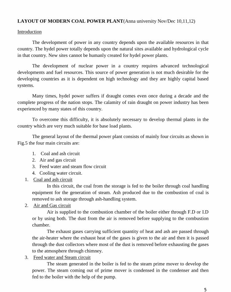
(iii) Impulse and reaction turbine.
In impulse turbine (Fig.9) the steam expands in the stationary nozzles and attains high
velocity. The resulting high velocity steam impinges against the blades which alter the direction
of steam jet thus changing the momentum of jet and causing impulsive force on the blades.
Fig.9 Impulse Turbine
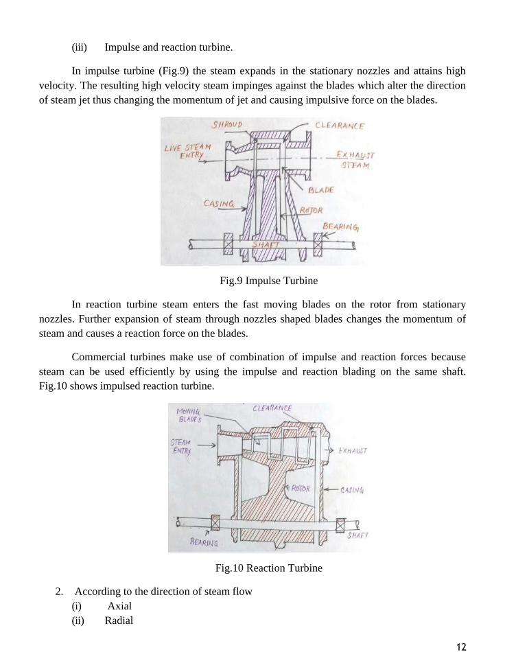
In reaction turbine steam enters the fast moving blades on the rotor from stationary
nozzles. Further expansion of steam through nozzles shaped blades changes the momentum of
steam and causes a reaction force on the blades.
Commercial turbines make use of combination of impulse and reaction forces because
steam can be used efficiently by using the impulse and reaction blading on the same shaft.
Fig.10 shows impulsed reaction turbine.
Fig.10 Reaction Turbine
2. According to the direction of steam flow
(i) Axial
(ii) Radial

13
(iii) Mixed
3. According to pressure of exhaust
(i) Condensing
(ii) Non-condensing
(iii) Bleeder
4. According to pressure of entering steam
(i) Low pressure
(ii) High pressure
(iii) Mixed pressure
5. According to step reduction
(i) Single stage
(ii) Multi-stage
6. According to method of drive such as
(i) Direct connected
(ii) Geared
CONDENSERS
The thermal efficiency of a closed cycle power developing system using steam as
working fluid and working on carnot cycle is given by an expression (T1-T2)/T1. This expression
of efficiency shows that the efficiency increases with an increase in temperature T1 and decrease
in temperature T2.
The maximum temperature T2(temperature at which heat is rejected) can be reduced to
the atmospheric temperature if the exhaust of the steam takes place below atmospheric pressure.
If the exhaust is at atmospheric pressure, the heat rejection is at 100˚C.
Low exhaust pressure is necessary to obtain low exhaust temperature. But the steam
cannot be exhausted to the atmosphere if it is expanded in the engine or turbine to a pressure
lower than the atmospheric pressure. Under this condition, the steam is exhausted into a vessel
known as condenser where the pressure is maintained below the atmosphere by continuously
condensing the steam by means of circulating cold water at atmospheric temperature.
A closed vessel in which steam is condensed by abstracting the heat and where the
pressure is maintained below atmospheric pressure is known as a condenser. The efficiency of
the steam plant is considerably increased by the use of a condenser. In large turbine plants, the
condensate recovery becomes very important and this is also made possible by the use of
condenser.
The steam condenser is one of the essential components of all modern steam power
plants. Steam condensers are of two types:
1. Surface condenser

14
(a) Down flow type
(b) Central flow condenser
(c) Evaporation condenser
2. Jet condenser
(a) Low level jet condensers (parallel flow type)
(b) High level or barometric condenser
(c) Ejector condenser
Surface condensers
In surface condensers there is no direct contact between the steam and cooling water and
the condensate can be re-used in the boiler. In such condenser even impure water can be used
for cooling purpose whereas the cooling water must be pure in jet condensers. Although the
capital cost and the space needed is more in surface condensers but it is justified by the saving in
running cost and increase in efficiency of plant achieved by using this condenser. Depending
upon the position of condensate extraction pump, flow of condensate and arrangement of tubes
the surface condensers may be classified as follows:
(a) Down flow type
Fig.11(a) shows a sectional view of down flow condenser. Steam enters at the top and flows
downward. The water flowing through the tubes in one direction lower half comes out in the
opposite direction in the upper half. Fig.11(b) shows a longitudinal section of a two pass down-
flow condenser.
Fig.11
(b) Central flow condenser
Fig.12 shows a central flow condenser. In this condenser the steam passages are
all around the periphery of the shell. Air is pumped away from the center of the
condenser.

15
The condensate moves radially towards the center of tube nest. Some of the
exhaust steam which moves towards the center meets the undercooling condensate and
pre-heats it thus reducing under cooling.
Fig.12
(c) Evaporation condenser.
In this condenser Fig.13 steam to be condensed in passed through a series of tubes
and the cooling water falls over these tube in the form of spray. A steam of air flows
over the tubes to increase evaporation of cooling water which further increases the
condensation of steam.
Fig.13 Evaporation condenser
Advantages
(i) The condensate can be used as boiler feed water.
(ii) Cooling water of even poor quality can be used because the cooling water does not
come in direct contact with steam.
(iii) High vacuum (about 73.5 of Hg) can be obtained in the surface condenser. This
increasing the thermal efficiency of the plant.
Disadvantages

16
(i) The capital cost is more
(ii) The maintenance cost and running cost this condenser is high
(iii) It is bulky and requires more space.
Jet condensers
In jet condensers the exhaust steam and cooling water come in direct contact with each
other. The temperature of cooling water and the condensate is same when leaving the
condensers.
Elements of the jet condenser are as follows:
(i) Nozzles or distributors for the condensing water.
(ii) Steam inlet
(iii) Mixing chambers: They may be (a) Parallel flow type (b) Counter flow type
depending on whether the steam and water move in the same direction before
condensation or whether the flows are opposite
(iv) Hot well
In jet condensers the condensing water is called injection water.
(a) Low level jet condensers (Parallel flow type)
In this condenser Fig.14 water is sprayed through jets and it mixes with steam.
The air is removed at the top by an air pump.
In counter flow type of condenser the cooling water flows in the downward
direction and the steam to be condensed moves upward.
Low level and high level jet condenser

17
(b) High level or Barometric condenser
Fig.15 shows a high level jet condenser. The condenser shell is place at a height
of 10.33m (barometric height) above the hot well. As compared to low level jet
condenser this condenser does not flood the engine if the water extraction pumps facts. A
separate air pump is used to remove the air.
(c) Ejector condenser
Fig.16 shows an ejector condenser. In this condenser cold water is discharged
under a head of about 5 to 6m through a series of convergent nozzles. The steam and air
enter the condenser through a non-return valve.
Steam gets condensed by mixing with water. Pressure energy is partly converted
into kinetic energy at the converging cones. In the diverging cone the kinetic energy is
partly converted into pressure energy and a pressure higher that atmospheric pressure is
achieved so as to discharge the condensate to the hot well.
Fig.16 Ejector condenser
FUEL HANDLING SYSTEM (COAL HANDLING)
Coal delivery equipment is one of the major components of plant cost. The various steps
involved in coal handling are as follows:
1. Coal Delivery
The coal from supply points is delivered by ships or boats to power stations
situated near to sea or river whereas coal is supplied by rail or trucks to the power
stations which are situated away from sea or river.

18
2. Unloading
The type of equipment to be used for unloading the coal received at the power
station depends on how coal is received at the power station. If coal is delivered by
trucks, there is no need of unloading device as the trucks may dump the coal to the
outdoor storage. Coal is easily handled if the lift trucks with scoop are used.
In case the coal is brought by railway wagons, ships or boats, the unloading may
be done by car shakes, rotary car dumpers, cranes, grab buckets and coal accelerators.
Rotary car dumpers although costly are quite efficient for unloading closed wagons.
Fig.17 Steps in coal Handling
3. Preparation
When the coal delivered is in the form of big lumps and it is not of proper size,
the preparation (sizing) of coal can be achieved by crushers, breakers, sizers driers and
magnetic separators.

19

20
4. Transfer
After preparation of coal is transferred to the dead storage by means of the
following systems:
(a) Belt conveyors
(b) Screw conveyors
(c) Bucket elevators
(d) Grab bucket elevators
(e) Skip hoists
(f) Flight conveyor
(a) Belt conveyor
Fig.18 shows a belt conveyor. It consists of an endless belt moving over a pair of
end drums(rollers). At some distance a supporting roller is provided at the center.
The belt is made up of rubber or canvas. Belt conveyor is suitable for the transfer
of coal over long distances. It is used in medium and large power plants. The initial cost
of the system is not high and power consumption is also low.
The inclination at which coal can be successfully elevated by belt conveyor is
about 20. Average speed of belt conveyor varies between 200-300 rpm. This conveyor
is preferred than other types.
Advantages of belt conveyor:
(1) Its operation is smooth and clean
(2) It requires less power as compared to other types of systems.
(3) Large quantities of coal can be discharged quickly and continuously.
(4) Material can be transported on moderate inclines
(b) Screw Conveyor
It consists of an endless helicoids screw fitted to a shaft (Fig.19) The screw while
rotating in a trough transfers the coal from feeding end to the discharge end.
This system is suitable, where coal is to be transferred over shorter distance and
space limitations exist. The initial cost of the system is low. It suffers from the
drawbacks that the power consumption is high and there is considerable wear of screw.
Rotation of screw varies between 75-125 r.p.m.
(c) Bucket elevator
It consists of buckets fixed to a chain Fig.20. The chain moves over two wheels.
The coal discharged at the top.
(d) Grab bucket elevator
It lifts and transfers coal on a single rail or track from one point to the other. The
coal lifted by grab buckets is transferred to overhead bunker or storage. This system
requires less power for operation and requires minimum maintenance.
The grab bucket conveyor can be used with crane or tower as shown in Fig.21
Although the initial cost of this system is high but operating cost is less.

21
(e) Skip hoist
It consists of a vertical or inclined hoist way a bucket or a car guided by a frame
and cable for hoisting the bucket. It is simple and compact method of elevating coal or
ash Fig.22 shows a skip hoist.
(f) Flight Conveyor
It consists of one or two strands of chain to which steel scrapes or flights are
attached, which scrap the coal through a trough having identical shape. This coal is
discharged in the bottom of trough. It is low in first cost but has large energy
consumption. There is considerable water.
Skip hoist and bucket elevators lift the coal vertically while belts and flight
conveyors move the coal horizontally or on inclines.
Fig. 23 shows a flight conveyor. Flight conveyors posses the following
advantages
(i) They can be used to transfer coal as well as ash.
(ii) The speed of conveyor can be regulated easily.
(iii) They have a rugged construction
(iv) They need little operational care.
Disadvantages:
(i) There is more wear due to dragging action.
(ii) Power consumption is more
(iii) Maintenance cost is high
(iv) Due to abrasive nature of material handle the speed of conveyors is low
(10 to 30m/min).
5. Storage of coal
It is desirable that sufficient quantity of coal should be stored. Storage of coal
gives protection against the interruption of coal supplies when there is delay in
transportation of coal or due to strikes in coal mines.
Also when the prices are low, the coal can be purchased and stored for future use.
The amount of coal to be stored depends on the availability of space for storage,
transportation facilities, the amount of coal that will whether away and nearness to coal
mines of the power station.
Usually coal required for month operation of power plant is stored in case of
power stations situated at longer distance from the collieries whereas coal need for about
15 days is stored in case of power station situated near to collieries. Storage of coal for
longer periods is not advantageous because it blocks the capital and results in
deterioration of the quality of coal.
The coal received at the power station is stored in dead storage in the form of
piles laid directly on the ground.

22
The coal stored has the tendency to whether (to combine with oxygen of air) and
during this process coal has some of its heating value and ignition quality. Due to low
oxidization the coal may ignite spontaneously. This is avoided by storing coal in the
form of piles which consists of thick and compact layers of coal so that air cannot pass
through the coal piles. This will minimize the reaction between coal and oxygen.
The other alternative is to allow the air to pass through layers of coal so that air
may remove the heat of reaction and avoid burning. In case the outer coal is to be stored
for longer periods the outer surface of piles may be sealed with asphalt or fine coal.
The coal is stored by the following methods.
(i) Stocking the coal in heats
The coal is piled on the ground up to 10-12m height. The pile top should
be given a slope in the direction in which the rain may be drained off.
The sealing of stored pile is desirable in order to avoid the oxidation of
coal after packing an air tight layer of coal.
Asphalt, fine coal dust and bituminuous coating are the materials
commonly used for this purpose.
(ii) Under water storage
The possibility of slow oxidation and spontaneous combustion can be
completely eliminated by storing the coal under water.
Coal should be stored at a site located on solid ground, well drained, free
of standing water preferably on high ground not subjected to flooding.rr
6. In plant Handling
From the dead storage the coal is brought to covered storage (live storage)(bins or
bunkers). A cylindrical bunker shown in Fig.24. In plant handling may include the
equipment such as belt conveyors, screw conveyors, bucket elevators etc., to transfer the
coal. Weigh lorries hoppers and automatic scales are used to record the quantity of coal
delivered to the furnace.
7. Coal weighing methods
Weigh lorries, hoppers and automatic scales are used to weigh the quantity of
coal. The commonly used methods to weigh the coal are as follows:
(i) Mechanical (ii) Pneumatic (iii) Electronics
The mechanical method works on a suitable lever system mounted on
knife edges and bearing connected to a resistance in the form of a spring of
pendulum.
The pneumatic weighters use a pneumatic transmitted weight head and the
corresponding air pressure determined by the load applied.
The electronic weighing machines make use of load cells that produce
voltage signals proportional to the load applied.

23
The important factors considered in selecting fuel handling surface systems are as follows:
(i) Plant flue rate
(ii) Plant location in respect to fuel shipping
(iii) Storage area available
ASH HANDLING SYSTEM
Boilers burning pulverized coal (PC) have dry bottom furnaces. The large ash particles
are collected under the furnace in a water-filled ash hopper. Fly ash is collected in dust
collectors with either an electrostatic precipitator or a bag house. A PC boiler generates
approximately 80% fly ash and 20% bottom ash. Ash must be collected and transported from
various points of the plants as shown in Fig.25. Pyrites, which are the rejects from the
pulverizers, are disposed with the bottom ash systems. Three major factors should be considered
for ash disposal systems.
1. Plant site
2. Fuel source
3. Environmental regulation
Fig.25 Ash collection and transportation
The sluice conveyor system (Fig. 26(a)) is the most widely used for bottom ash handling,
while the hydraulic vacuum conveyor (Fig. 26(b)) is the most frequently used for fly ash
systems.

24
Fig. 26 (a) Bottom ash sluice conveyor, (b) fly ash hydraulic vacuum conveyor
Bottom ash and slag may be used as filling material for road construction. Fly ash can
partly replace cement for making concrete. Bricks can be made with fly ash. These are durable
and strong.
DRAUGHT SYSTEM
The purpose of draught is as follows:
(1) The supply required amount of air to the furnace for the combustion of fuel. The amount
of fuel that can be burnt per square foot of grate area depends upon the quantity of air
circulated through fuel bed.
(2) To remove the gaseous products of combustion
Definition
Draught is defined as the difference between absolute gas pressure at any point in a gas
flow passage and the ambient (same elevation) atmospheric pressure.
Draught is plus is Patm<Pgas and it is minus Patm>Pgas. Draught is achieved by small
pressure difference which causes the flow of air or gas to take place. It is measured in millimeter
(mm) of water.
If only a chimney is used to create the necessary draught, the system is called natural
draught system and if an addition to chimney a forced draught(F.D) fan or an induced draught
(I.D) fan or both are used the system is called mechanical draught system.
Fans or chimneys produce positive pressure and is called available draught whereas fuel
bed resistance, turbulence and friction in air ducts, gas breechings, chimney etc., create negative
pressure and is called the required draught.

25
The various types of draught system are as follows:
(i) Natural draught
(ii) Mechanical draught
(iii) Steam jet draught
Natural draught
Fig.27 Natural Draught system
Natural draught system is used in boilers of smaller capacities. Natural draught is created
by the difference in weight of a column of cold external air and that of a similar column of hot
gases in the chimney. This system is dependent upon the height of chimney and average
temperature of the gases in the chimney.
Now-a-days the chimney is not used for creating draught in steam power plants as it has
no flexibility, the total draught produced is insufficient for high generating capacity.
By using chimney draught can be increased by allowing the flue gases to leave the
combustion chamber at higher temperature and this reduced the overall efficiency of the power
plant. The chimney is, therefore, used only to discharge the flue gases.
Mechanical Draught
In boilers of large capacities, fans are employed to create the necessary draught in order
to reduce the height of chimney, to obtained draught that is independent of weather conditions
and to control the draught easily.
Mechanical draught may be induced forced or balanced draught. Induced draught system
shown in Fig. 28(a) is created by chimney and fan located in the gas passage on the chimney side
of the boiler. In this system gas movement is achieved as result of vacuum
The various pressures indicated are as follows:
P1 = Inlet pressure for forced draught fan
P2 = Outlet pressure of forced draught fan

26
P3 = Pressure below grate
P4 = Pressure above the grate
P5 = Inlet pressure of induced draught fan
P6 = Outlet pressure of induced draught fan
Fig.28 Mechanical draught system
Induced draught is not as simple and direct as forced because fans used in induced
draught system operate in gases of much higher temperature (nearly 500˚-904˚F). Thus becomes
more expensive.
The fan sucks in gas from the boiler side and discharges it to the chimney (stack)
The draught produced is independent of the temperature of the hot gases and, therefore,
the gases may be discharged as cold as possible after recovering as much heat possible in air
preheater and economizer.
In FD system (Fig.28 (b)) the fan installed near the boiler base supplies the air at a
pressure above that of atmosphere and delivers it through air duct to the furnace

27
Most high rating combustion equipment employs forced draught fans for supplying air to
the furnace. Forced draught is used in under fed stockers carrying a thick fuel bed. Balanced
draught system is a combination of induced and forced draught systems.
The forced draught fan forces the air through the fuel bed on to the top of grate and the
induced draught fan sucks in gases from the boiler side and discharges them to the chimney.
This system is used where pressure above fire is slightly below atmosphere (Fig.32(c)) shows
this system.
Steam Jet Draught
Steam jet draught may be induced or forced draught depending upon the location of
steam jet producing the draught.
Induced draught produced by steam jet as shown in Fig.29. This system is used in
locomotive boilers. Exhaust steam from the engine enters the smoke box through a nozzle to
create draught. The air is induced through the flues, the grate and ash pit to the smoke box.
Fig.29 Steam Jet Induced Draught System
Fig.30 shows a forced draught developed by steam jet. Steam from the boiler is passed
through a throttle valve, throttle pressure being 1.5 to 2kg/cm2 gauge.
Then the steam passes through a nozzle projecting in diffuser pipe. The steam comes out
of nozzle with great velocity and drags a column of air along with it thus allowing the fresh air to
enter.
The mixture of steam and air possesses high kinetic energy and passes through the
diffuser pipe. The kinetic energy gets converted into pressure energy and thus air is forced
through the coal bed, furnace and flows to the chimney. Steam jet is simple, requires less space
and is economical. But is can be used only if steam at high pressure is available.

28
Fig.30 Steam-Jet forced draught system
FEEDWATER TREATMENT
Boiler make-up water to the extent of 1.5—2 percent of the total flow rate is required to
replenish the losses of water through leakage from fittings and bearings, boiler blow down,
escape with non-condensable gases in the deaerator, turbine glands, and other causes. This make-
up water needs to be treated prior to feeding it to the boiler for
1. Prevention of hard scale formation on the heating surfaces
2. Elimination of corrosion
3. Control of carry-over to eliminate deposition on superheater tubes, and
4. Prevention of silica deposition and corrosion damage to turbine blades.
Raw water is, therefore, first pre-treated and then demineralized. For once through
boilers and boiling water nuclear reactors, which require high water purity, a condensate
polishing system is used to further polish the water. Raw water contains a variety of impurities,
such as (a) Suspended solids and turbidity, (b) organics, (c) hardness (salts of calcium and
magnesium), (d) alkalinity (bicarbonates, carbonates, and hydrates), (e) other dissolved ions
(sodium, sulphate, chloride, etc.,), (f) silica and (g) dissolved gas( O2, CO2). The extent of pre-
treatment depends on the source of raw water.
1. External treatment
The first step of pre-treatment of boiler feed water is clarification, in which the
water is chlorinated to prevent biofouling of the equipment. The suspended solids and
turbidity are coagulated by adding special chemicals (like aluminiumsulphate, Al2(SO4)3)
and agitated. The coagulated matter settles at the bottom of the clarifier and is removed.
If the turbidity of clarified effluent is high, positive filtration is needed. Both
gravity filters and pressure-type filters are used, but the latter is preferred. A granular
medium like sand is commonly used for filtration. The pressure difference across the
filtering medium is an indication of solid accumulation. When it reaches a given limit,

29
the solids are removed from the bed by backwashing. Further filtration by activated
carbon can absorb organics and remove residual chlorine from the chlorination process.
The dissolved salts of calcium and magnesium give to water a quality called
hardness. Hardness is characterized by the formation of insoluble precipitates or curds
with soaps, and is usually measured with a standard soap test. All natural waters are hard
and contain scale-forming impurities which are mainly the salts of calcium and
magnesium in the form of carbonates, bicarbonates, chlorides and sulphates. The
hardness is expressed in ppm of dissolved salts. Softening of water, i.e removal of
hardness from water, can be done by lime-soda process, phosphates process, zeolite
process and demineralization.
2. Lime—soda process
In lime—soda softening, calcium and magnesium salts are removed using lime
(calcium hydroxide) and soda ash (sodium carbonate). When this process is carried out
at normal raw-water temperature, it is called a “cold process” softening; and when carried
out at or near the boiling point, it is referred to as a “hot process” softening. Since
heating greatly accelerates the necessary reactions, the hot process is preferred for boiler
water treatment, where most of the energy used in heating the water may be retained in
the cycle. The representative reactions are given below:
Ca(HCO3)2+Ca(OH)2 =2CaCO3+2H2O
MgCl2+Ca(OH)2=Mg(Oh)2+CaCl2
MgSO4+Ca(OH)2=Mg(OH)2+CaSO4
CaSO4+Na2CO3=CaCO3+Na2SO4
CaCl2+Na2CO3=CaCO3+2NaCl
The products, calcium carbonate and magnesium hydroxide are insoluble in water
and settle to the bottom of the vessel. The softened effluent is then passed through sand
or charcoal filters before usage.
3. Hot phosphate Softening
In the hot phosphate softening process, calcium and magnesium hardness is
removed using phosphate and caustic soda, Tricalcium phosphate (Ca3(PO4)2) and
magnesium hydroxide are precipitated. The process is carried out at a temperature of
100˚C or above. Since the hot phosphate process requires more expensive chemicals than
the lime—soda process, it is used where the initial water hardness is 60 ppm or less.
Where hardness is greater than this, a lime soda process may be used first, followed by a
phosphate clean-up. The representative reactions are given below:
3Ca(HCO3)2+6NaOH=2CaCO3+2Na2CO3+6H2O
CaCO3+2Na3PO4=Ca3(PO4)2+2Na2CO3
Mg(HCO3)2+4NaOH=Mg(OH)2+2Na2CO3+2H2O
3CaSO4+2Na3PO4=Ca3(PO4)2+3Na2SO4

30
4. Sodium Zeolite Softening
Water can be softened by passing it through a bed of sodium zeolite, which may
be natural compounds of sodium aluminium silicate, with the cations of calcium and
magnesium removed in the process.
CaCO3+Na2A=CaZ+Na2CO3
MgSO4+Na2Z=MgZ+Na2SO4
Ca(HCO3)2+Na2Z=CaZ+Na2(HCO3)2
The softening capacity of the bed gets exhausted in course of time, and the bed
can be regenerated by flushing it with brine (NaCl),
CaZ+2NaCl=Na2Z+CaCl2
MgZ+2NaCl=Na2Z+MgCl2
Zeolite softening is not ideal for the following reasons: (i) Water of high or low
pH have a deleterious effect on zeolites, (ii) high temperatures also have a bad effect,
(iii) turbid waters coat the zeolite material, reducing its efficiency, (iv) there is no
reduction in alkalinity or total solids, (v) there can be silica gain in water from the zeolite,
(vi) with low content of calcium, the water can be corrosive, sodium zeolite softening in
conjunction with the use of evaporating may be more effective.
5. Hydrogen Zeolite softening
When water containing calcium, magnesium and sodium ions is passed through a
hydrogen zeolite, these ions are exchanged for hydrogen and the bicarbonate, sulphate,
chloride and nitrate radicals are converted to their respective acids. Typical reactions are:
Ca Ca
(Mg)(HCO3)2+H2Z=(Mg)Z+2H2CO3
(Na2) (Na2)
(Ca) (Ca)
(Mg)SO4+H2Z = (Mg)Z+H2SO4
(Na2) (Na2)
When the hydrogen zeolite becomes exhausted, it is backwashed and regenerated
with acid. After being rinsed, it is ready for use again. Sulphuric acid is generally used
for regeneration because of its relatively low cost.
MgZ+H2SO4=H2Z+MgSO4
CaZ+H2SO4=H2Z+CaSO4
6. Anion exchangers
Anion exchangers can remove the anions like chlorides, sulphates and nitrates
(acid forms) present in hydrogen zeolite effluent by resinous materials which absorb
them. Typical reactions are:
2HCl+RCO3=RCl2+H2CO3
H2SO4+RCO3=RSO4+H2CO3
2HNO3+RCO3=R(NO3)2+H2CO3

31
Carbonic acid is removed by aeration. When the acidic water is sprayed in a
shower to expose large surface area, the carbon dioxide gas is released.
H2CO3 CO2+H2O
When the anion exchanger is exhausted, it is regenerated by backwashing with
soda ash
RCl2+Na2CO3=RCO3+2NaCl
RSO4+Na2CO3+RCO3+Na2SO4
7. Demineralizing plant
The process of removing dissolved solids in water by ion exchange is called
demineralization. Two types of resins, cation and anion, are used. The cation resin is the
hydrogen zeolite where the hydrogen ion is exchanged for the cations calcium,
magnesium and sodium, and the anion resin adsorbs the anions chlorides, nitrates and
sulphates, as discussed above. Both ion-exchange processes are reversible, and the resins
are restored to their original form by regeneration.
A typical Demineralizing plant consisting of a cation exchanger, an anion
exchanger, a degasfier and a silica adsorber in series is shown in Fig.31. In the
degasifier, carbon dioxide gas is removed by aeration. Silica in water is very detrimental
at high pressure. It vaporizes at high pressure and flows with steam, condenses on
turbine blades in the form of hard glassy scales which are difficult to remove.
Magnesium hydroxide is often used to adsorb silica from water.
The membrane treatment for removing the total dissolved solids from make-up
water is also an energy efficient process and is gradually gaining more acceptances. It
uses the principle of either reverse osmosis or electro dialysis. The driving force for
reverse osmosis is the application of counter pressure to normal osmotic pressure, driving
water molecules through the membranes in preference to dissolved salts.
Fig.31 A typical Demineralizing plant

32
8. Condensate polishing
A high quality make-up water can be produced for the plant by using
Demineralizing systems as discussed above. However, this treated water while flowing
through the cycle can pick up impurities due to condenser leakage from the circulating
water through the tubes as well as metallic ions, such as iron and copper, from pipelines.
Condensate polishing is accomplished by passing the condensate through large
Demineralizing vessels, called mixed bed units, which contain both cation and anion
resins. The resins not only remove dissolved salts in the above manner, but also act as
filters for impurities or suspended solids. Power plants using once-through boilers and
nuclear reactors generally require high quality water and use condensate polishing
systems.
BINARY CYCLES
No single fluid can meet all the requirements as mentioned above. Although in the
overall evaluation water is better than any other working fluid, at high temperatures, however,
there are a few better fluids and notable among them are :
(a) Diphenyl ether (C6H5)2O
(b) Aluminium bromide AlBr3
(c) Liquid metals like mercury, sodium, potassium and so on. Among these only mercury
has actually been used in practice.
Fig.32 Flow diagram of mercury-steam binary cycle

33
Diphenyl ether could be considered but it has not yet been used because like most organic
substances, it decomposes gradually at high temperatures. Aluminium bromide is a possibility
and yet to be considered.
As at pressure of 12 bar, the saturation temperatures for water, aluminium bromide and
mercury are 187˚C,482.5˚C and 560˚C, its vaporization pressure is relatively low. Its critical
pressure and temperature are 1080 bar and 1460˚C respectively.
But in the low temperature range, mercury is unsuitable because its saturation pressure
becomes exceedingly low, and it would be impractical to maintain such a high vacuum in the
condenser.
At 30˚C the sayturation pressure of mercury is only 2.7x10⁻⁴
cm Hg. Its specific volume
at such a low pressure is very large, and it would be difficult to accommodate such a large
volume flow.
Fig.33 T-S diagram of mercury-steam binary cycle
For this reason, to make advantage o f the beneficial features of mercury in the high
temperature range and to get rid of its deleterious effects in the low temperature range, mercury
vapour leaving the mercury turbine is condensed at a higher temperature and pressure, and the
heat released during the condensation of mercury is utilized in evaporating water to form steam
to operate on a conventional turbine.
Thus, in the binary (or two fluid) cycle, two cycles with different working fluids are
coupled in series, the heat rejected by on being utilized in the other.
The flow diagram of mercury-steam binary cycle and the corresponding T-S diagram are
given in Fig.32&33 respectively.

34
The mercury cycle a-b-c-d is a simple rankine cycle saturated vapour. The heat rejected
by mercury during condensation (process b-c) is transferred to boil water and form saturated
vapour (process 5-6).
The saturated vapour is heated from the external source (furnace) in the super
heater(process 6-1). Super heated steam expands in the turbine and is then condensed. The
condensate is then pumped to the economizer where it is heated till it becomes saturated liquid
by the outgoing flue gases (process4-5).
The saturated liquid then goes to the mercury condenser-steam boiler , where the latent
heat is absorbed. In an actual plant, the steam cycle is always a regenerative cycle with feed
water heating, but for the sake of simplicity, this complication has been omitted.
Let m represent the flow rate of mercury in the mercury cycle per kg of steam circulating
in the steam cycle. Then , for 1 kg of steam,
-------------(1)
������ = �1 − �2
�1
�� − �� =
�1
3600
���
����� ���� (���) =
�� − �� ��/��ℎ
The energy balance of the mercury condenser-steam boiler gives
m(hb-hc) =(h6-h5)
therefore, ℎ 6 − ℎ 5
��
� = ℎ�
− ℎ �
�� ��
�2�
To vaporize one kg of water, 7 to 8 kg of mercury must be mercury.
COGENERATION SYSTEMS
Q1 = m(ha-hd)+(h1-h6)+(h5-h4)
Q2 = h2-h3
WT = m(ha-hb)+(h1-h2)
WP = m(hd-hc)+(h4-h3)

35
There are several industries such as paper mills, textile mills, chemical factories, jute
mills, sugar factories, rice mills and so on where saturated steam at the desired temperature is
required for heating, drying etc.
For constant temperature heating (or drying), steam is a very good medium since
isothermal condition can be maintained by allowing saturated steam to condensate at that
temperature and utilizing the latent heat released for heating purposes.
Apart from the process heat, the factory also needs power to drive various machines, for
lighting and other purpose.
Earlier, steam of power purposes was generated at a moderate pressure and saturated
steam of process work was generated separately at a pressure which gave the desired heating
temperature.
Having two separate units for process heat and power is wasteful, for the total heat
supplied to the steam generator for power purposes, a greater part will normally be carried away
by the cooling water in the condenser.
Back pressure Turbine
By modifying the initial steam pressure and exhaust pressure, it is possible to generate
the required power and make available the required quantity of exhaust steam at the desired
temperature for process work.
In Fig.34, the exhaust steam from the turbine is utilized for process heating, the process
heater replacing the condenser of the ordinary rankine cycle.
Fig.34 cogeneration plant with a back-pressure turbine

36
The pressure at exhaust form the turbine is the saturation pressure corresponding to the
temperature desired in the process heater such a turbine is called a back pressure turbine.
A plant producing both electrical power and process heat simultaneously is called a
cogeneration plant.
When the process steam is the basic need, and the power is produced incidentally as a by-
produce the cycle is often called a byproduct power cycle.
Fig.35 by product power cycle with a back-pressure turbine
Fig.35 shows the T-S plot for such a cycle. If WT is the turbine output in kW, QH is the
process heat required in kJ/h, and ws are the steam flow rate in kg/h.
�� × 3600 = ��(ℎ 1 − ℎ 2)���
�� = ��(ℎ 2 − ℎ 3)
�� ��
× 3600 = ℎ 2 − ℎ 3
(ℎ
1 − ℎ 2)
�� �� × 3600 × (ℎ 2 − ℎ 3)
= (ℎ 1 − ℎ 2)
�� − − − −(1)
ℎ
Of the total energy input Q1 (as heat) to the co-generation plant, WT part of it only is
converted into shaft work or electricity.
The remaining energy (Q1-WT), which would otherwise have been a waste, as in the
rankine cycle, by second law, it is utilized as process heat.
The co-generation plant efficiency ήco is given by
��� =
�� + �� − − − − − (2)
�1

37
For separate generation of electricity and steam, the heat added per unit total energy
output is,
1
��
1 − � +
�ℎ
Where e = electricity fraction of total energy output
��
ήe= electric plant efficiency
= �� + ��
ήh= steam (or process heat) generator efficiency
The combined efficiency ήc for separate generation is therefore given by
�� =
�
��
1
1−� − − − − − (3) +
�ℎ
Cogeneration is beneficial if the efficiency of the co-generation plant, equation (2),
greater than that of separate generation, equation (3)
Back pressure turbines are quite small with respect to their power output because they
have no great volume of exhaust to cope with, the density being high. They are usually single
cylinder and hence, cheap in terms of cost per MW compared to condensing sets of the same
power.
Besides their use in process industries and petrochemical installations, back pressure
turbines are used for desalination of sea-water, district heating, and also for driving compressors
and feed pumps.