Embed Size (px)
Citation preview
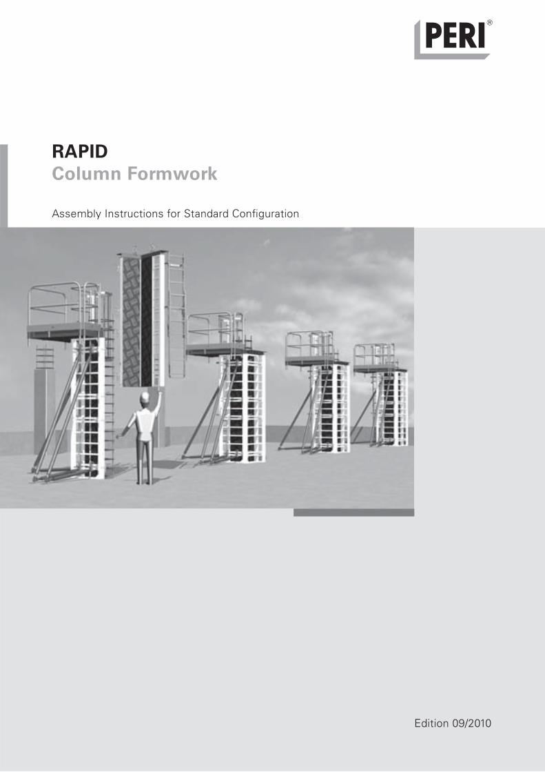
RAPIDColumn Formwork
Edition 09/2010
Assembly Instructions for Standard Configuration

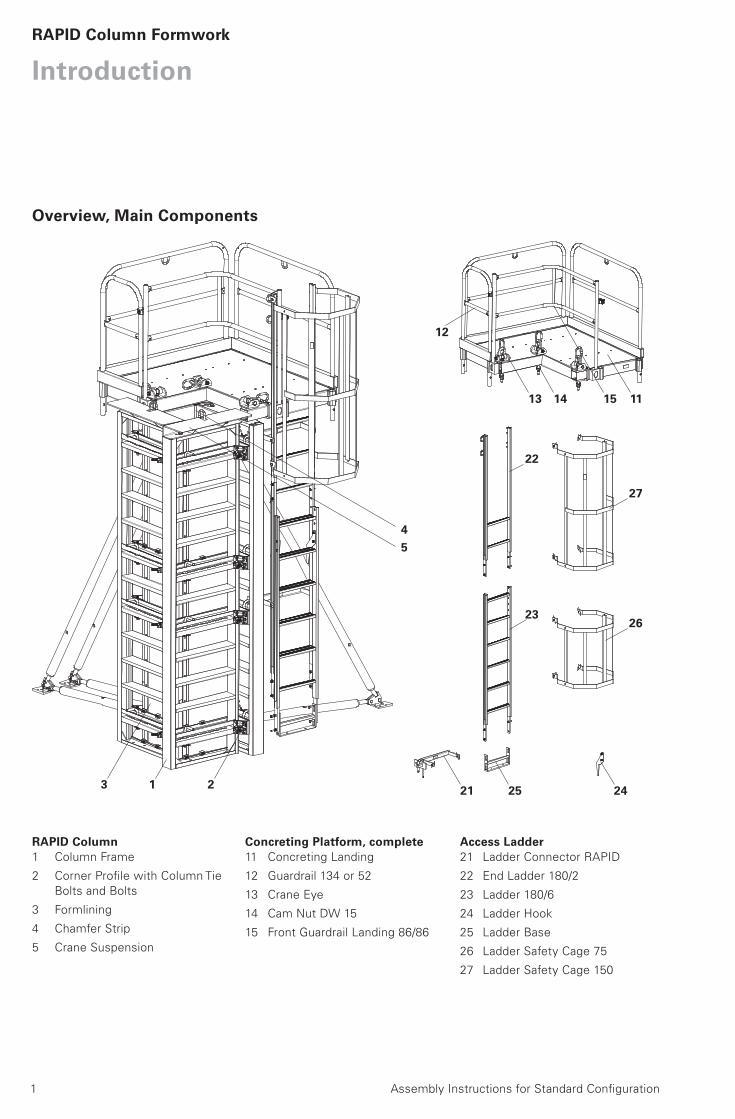
Introduction Overview, Main Components 1
Standard Configuration 2
Intended Use 2
Safety Instructions 3
General 3
A Assembly and DismantlingA1 Cleaning
Cleaning 4
A2 Assembly
Formlining Installation with Chamfer Strip 5
Push-Pull Props 8
Concreting Platform 9
Access Ladder 10
Parts list for Access Ladders 11
A3 Shuttering
Placing of Formwork 12
Installation of Reinforcement 13
Closing of Formwork 13
A4 Striking and Moving
Striking and Moving 14
A5 Oversized Column Cross-Sections
Oversized Column Cross-Sections 15
A6 Height Adjustment
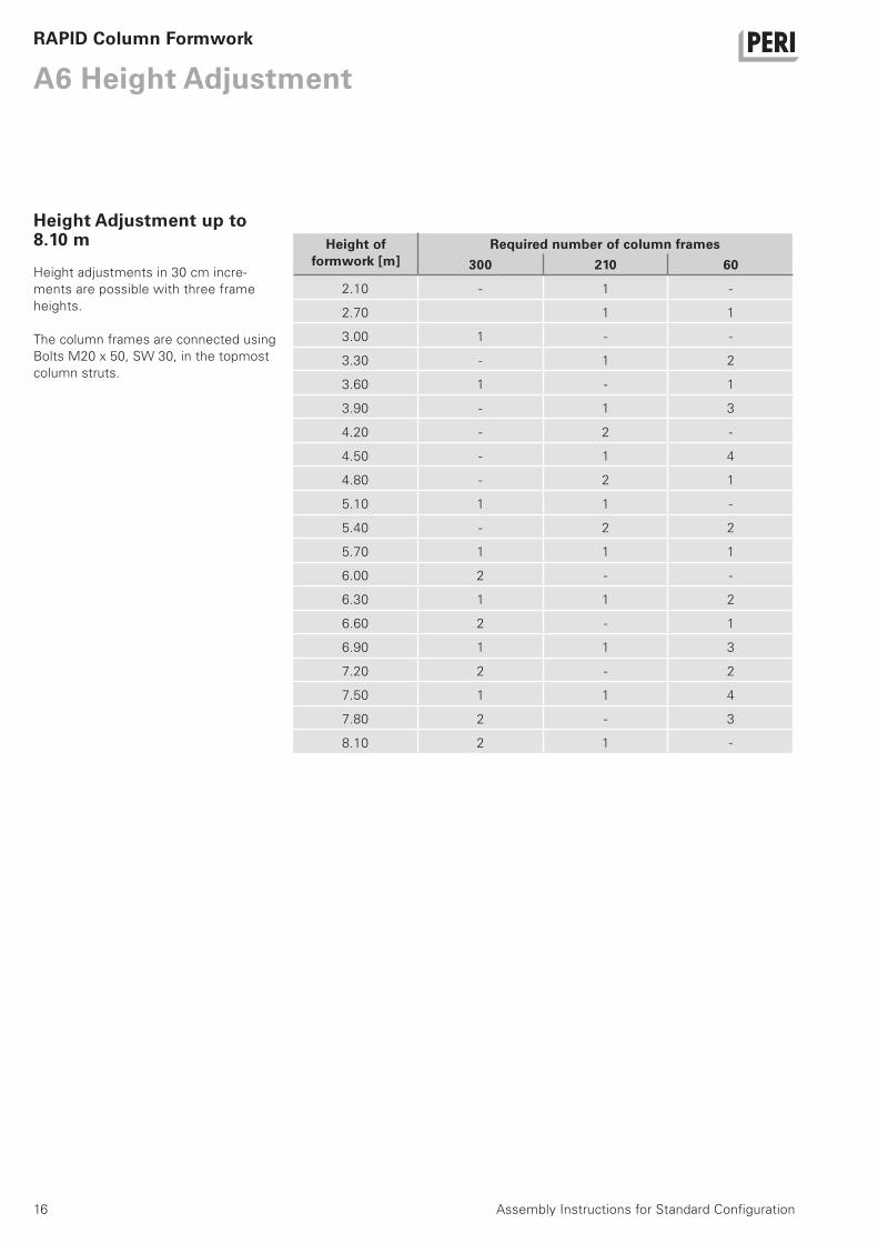
Height Adjustment up to 8.10 m 16
Components Components 18
Key
Safety Instructions Note Visual Check Tip
Assembly Instructions for Standard Configuration
ContentRAPID Column Formwork
1 Assembly Instructions for Standard Configuration
IntroductionRAPID Column Formwork
RAPID Column1 Column Frame
2 Corner Profile with Column Tie
Bolts and Bolts
3 Formlining
4 Chamfer Strip
5 Crane Suspension
45
Concreting Platform, complete11 Concreting Landing
12 Guardrail 134 or 52
13 Crane Eye
14 Cam Nut DW 15
15 Front Guardrail Landing 86/86
Access Ladder21 Ladder Connector RAPID
22 End Ladder 180/2
23 Ladder 180/6
24 Ladder Hook
25 Ladder Base
26 Ladder Safety Cage 75
27 Ladder Safety Cage 150
13 111514
2521 243 1 2
27
26
22
23
12
Overview, Main Components
2 Assembly Instructions for Standard Configuration
RAPID Column Formwork
Introduction
GeneralPERI RAPID is the column formwork for
joint-free architectural concrete. The
column frame is made of aluminium
and powder-coated to ensure easy and
simple cleaning. The cut-to-size formlin-
ing sheets are firmly connected to the
frame by means of clamping profiles.
As a result, no screw or nail impres-
sions are visible on the concrete sur-
face. With extended column frames,
the plywood formlining can be continu-
ously fitted over the joints of the col-
umn frames. Sharp-edged column
cross-sections can be realised through
the use of chamfer strips. Through the
formwork element arrangement, which
is based on the windmill vane principle,
both square and rectangular column
cross-sections can be continuously
formed.
System DimensionsFormwork height:Maximum 8.10 m, extendable in 30 cm
increments.
Column cross-sections:Continuously adjustable square or rectan-
gular cross-sections of up to 60 x 60 cm.
With sharp-edged designs, a maximum
of 58 x 58 cm.
Oversized cross-sections from 85 x 85 cm
to 135 x 135 cm with additional ties
through the concrete.
Thickness of the plywood formlining:21 mm for columns with chamfer strips,
30 mm for sharp-edged columns.
Technical DataPermissible fresh concrete pressure
120 kN/m².
Standard Configuration
Intended Use1. PERI products have been designed
as technical work equipment for exclu-
sive use in the industrial and commer-
cial sectors by suitably trained person-
nel.
2. These assembly instructions serve as
the basis for the project-related risk as-
sessment and the instructions for the
provision and use of the system by the
contractor (user). However, they do not
replace these.
3. Only PERI original components may
be used. The use of other products and
spare parts represents a misapplication
with associated safety risks.
4. The components are to be inspected
before each use to ensure that they are
in perfect condition and function cor-
rectly.
5. Changes to PERI components are
not permitted and represent a misappli-
cation with associated safety risks.
6. Safety instructions and permissible
loads must be observed at all times.
7. Components provided by the contrac-
tor must conform with the characteris-
tics required in these assembly instruc-
tions as well as all valid construction
guidelines and standards.
In particular, the following apply if noth-
ing else is specified:
– timber components: Strength Class
C24 for Solid Wood EN 338.
– scaffold tubes: galvanised steel tub-
ing with minimum dimensions Ø 48.3
x 3.2 mm according to EN 12811-
1:2003 4.2.1.2.
– scaffold tube couplings according to
EN 74.
8. Deviations from the standard config-
uration may only be carried out after a
separate risk assessment has been
completed by the contractor (user). On
this basis, appropriate measures for the
working safety and stability are to be
implemented.

3Assembly Instructions for Standard Configuration
RAPID Column Formwork
Safety Instructions
General1. Deviations from the standard configu-
ration and/or intended use present a
potential safety risk.
2. All country-specific laws, standards
and other safety regulations are to be
taken into account whenever our prod-
ucts are used.
3. During unfavourable weather condi-
tions, suitable precautions and meas-
ures are to be taken in order to ensure
both working safety and stability.
4. The contractor (user) must ensure
the stability throughout all phases of
construction. He must ensure and veri-
fy that all loads which occur can be
safely transferred.
5. The contractor (user) has to provide
safe working areas for site personnel
which are to be reached through the
provision of safe access means. Areas
of risk must be cordoned off and clearly
marked. Hatches and openings on ac-
cessible working areas must be kept
closed during working operations.
6. For better comprehensibility, detailed
drawings are partly incomplete. The
safety installations which have possibly
not been featured in these detailed
drawings must nevertheless be available.
Storage and Transportation1. Do not drop the components.
2. Store and transport components en-
suring that no unintentional change in
their position is possible. Detach lifting
gear from the lowered units only if
these are in a stable position and no
unintentional change is possible.
3. When moving the components, make
sure they are lifted and set down so
that any unintentional tipping over, fall-
ing apart, sliding or rolling away are
avoided.
4. Use only suitable load-carrying equip-
ment to move the components as well
as the designated load-bearing points.
5. During the lifting and moving proce-
dure, ensure all loose parts are re-
moved or secured.
6. During the moving procedure, always
use a guide rope.
7. Move components on clean, flat and
sufficiently load-bearing surfaces only.
System-specific1. Retract components only when the
concrete has sufficiently hardened and
the person in charge has given the go-
ahead for striking to take place.
2. Anchoring is to take place only if the
anchorage has sufficient concrete
strength.
3. Only use designated PERI lifting ac-
cessories.
4. During striking, do not tear off the
formwork panels with the crane.
5. If a storm warning is given, addition-
al push-pull props are to be attached or
other bracing measures are to be car-
ried out along with implementing the
details contained in the PERI design ta-
bles.
The assemblies shown in these PERI
assembly instructions are only exam-
ples which feature only one component
size. They apply accordingly for all com-
ponent sizes contained in the standard
configuration.
Additional PERI product information– RAPID column formwork brochure
– PERI design tables
General
Introduction
4 Assembly Instructions for Standard Configuration
RAPID Column Formwork
A1 Cleaning
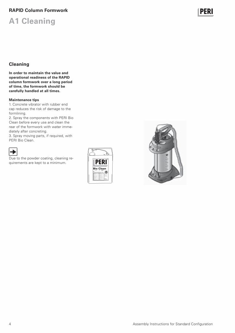
In order to maintain the value and operational readiness of the RAPID column formwork over a long period of time, the formwork should be carefully handled at all times.
Maintenance tips1. Concrete vibrator with rubber end
cap reduces the risk of damage to the
formlining.
2. Spray the components with PERI Bio
Clean before every use and clean the
rear of the formwork with water imme-
diately after concreting.
3. Spray moving parts, if required, with
PERI Bio Clean.
Due to the powder coating, cleaning re-
quirements are kept to a minimum.
Cleaning
5Assembly Instructions for Standard Configuration
RAPID Column Formwork
A2 Assembly
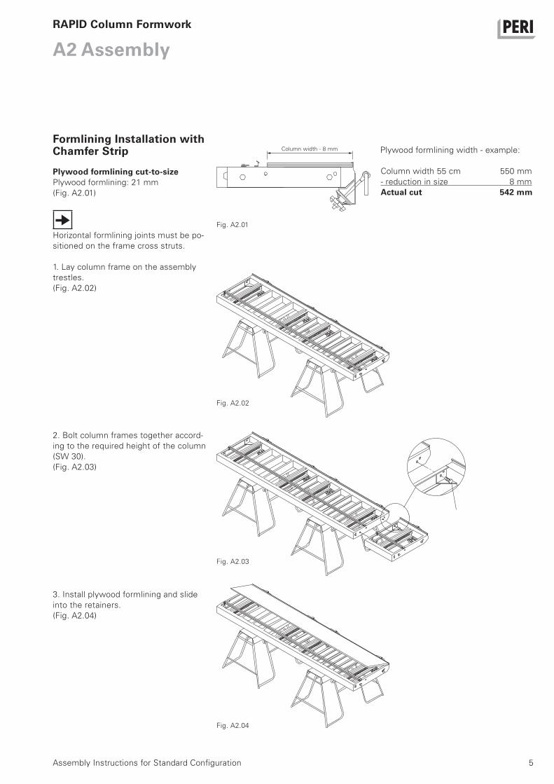
Plywood formlining cut-to-sizePlywood formlining: 21 mm
(Fig. A2.01)
Horizontal formlining joints must be po-
sitioned on the frame cross struts.
1. Lay column frame on the assembly
trestles.
(Fig. A2.02)
Plywood formlining width - example:
Column width 55 cm 550 mm
- reduction in size 8 mm
Actual cut 542 mm
2. Bolt column frames together accord-
ing to the required height of the column
(SW 30).
(Fig. A2.03)
3. Install plywood formlining and slide
into the retainers.
(Fig. A2.04)
Fig. A2.01
Fig. A2.02
Fig. A2.03
Fig. A2.04
Formlining Installation with Chamfer Strip Column width - 8 mm
6
A2 Assembly
Assembly Instructions for Standard Configuration
RAPID Column Formwork
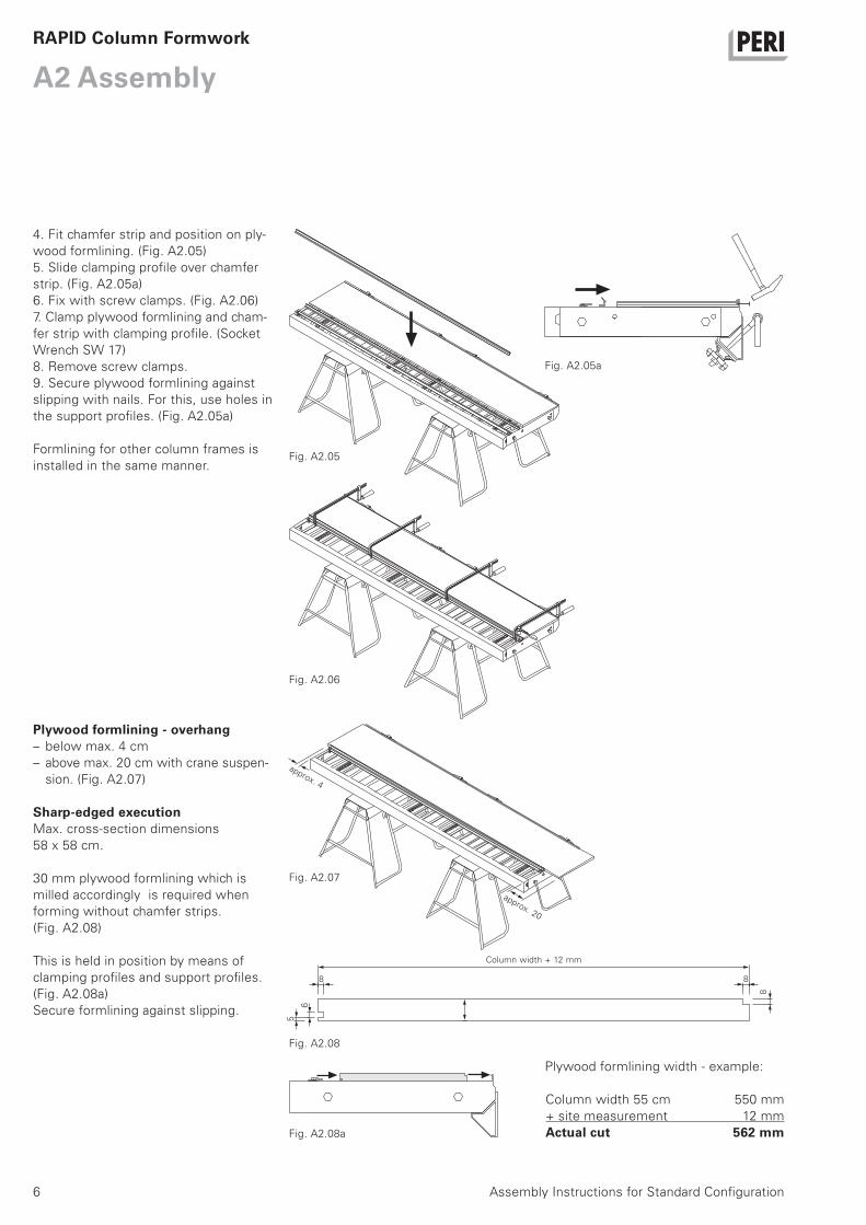
4. Fit chamfer strip and position on ply-
wood formlining. (Fig. A2.05)
5. Slide clamping profile over chamfer
strip. (Fig. A2.05a)
6. Fix with screw clamps. (Fig. A2.06)
7. Clamp plywood formlining and cham-
fer strip with clamping profile. (Socket
Wrench SW 17)
8. Remove screw clamps.
9. Secure plywood formlining against
slipping with nails. For this, use holes in
the support profiles. (Fig. A2.05a)
Formlining for other column frames is
installed in the same manner.
Plywood formlining - overhang– below max. 4 cm
– above max. 20 cm with crane suspen-
sion. (Fig. A2.07)
Sharp-edged executionMax. cross-section dimensions
58 x 58 cm.
30 mm plywood formlining which is
milled accordingly is required when
forming without chamfer strips.
(Fig. A2.08)
This is held in position by means of
clamping profiles and support profiles.
(Fig. A2.08a)
Secure formlining against slipping.
Plywood formlining width - example:
Column width 55 cm 550 mm
+ site measurement 12 mm
Actual cut 562 mm
Fig. A2.06
Fig. A2.05
Fig. A2.05a
Fig. A2.07
Fig. A2.08a
Fig. A2.08
Column width + 12 mm
8
5
6
8
8
approx. 20
approx. 4
7Assembly Instructions for Standard Configuration
A2 AssemblyRAPID Column Formwork
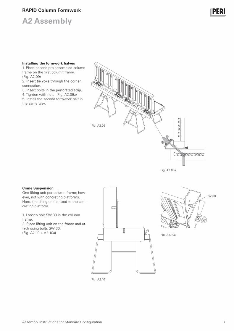
Installing the formwork halves1. Place second pre-assembled column
frame on the first column frame.
(Fig. A2.09)
2. Insert tie yoke through the corner
connection.
3. Insert bolts in the perforated strip.
4. Tighten with nuts. (Fig. A2.09a)
5. Install the second formwork half in
the same way.
Crane SuspensionOne lifting unit per column frame; how-
ever, not with concreting platforms.
Here, the lifting unit is fixed to the con-
creting platform.
1. Loosen bolt SW 30 in the column
frame.
2. Place lifting unit on the frame and at-
tach using bolts SW 30.
(Fig. A2.10 + A2.10a)
Fig. A2.09
Fig. A2.09a
Fig. A2.10
Fig. A2.10a
SW 30
8
A2 Assembly
Assembly Instructions for Standard Configuration
RAPID Column Formwork
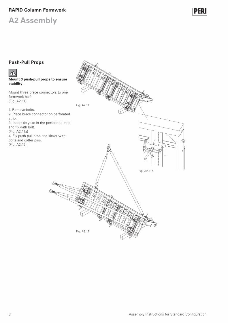
Mount 3 push-pull props to ensure stability!
Mount three brace connectors to one
formwork half.
(Fig. A2.11)
1. Remove bolts.
2. Place brace connector on perforated
strip.
3. Insert tie yoke in the perforated strip
and fix with bolt.
(Fig. A2.11a)
4. Fix push-pull prop and kicker with
bolts and cotter pins.
(Fig. A2.12)
Fig. A2.11
Fig. A2.11a
Fig. A2.12
Push-Pull Props
9Assembly Instructions for Standard Configuration
A2 AssemblyRAPID Column Formwork
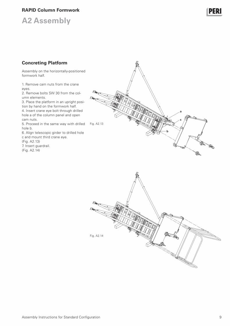
Assembly on the horizontally-positioned
formwork half.
1. Remove cam nuts from the crane
eyes.
2. Remove bolts SW 30 from the col-
umn elements.
3. Place the platform in an upright posi-
tion by hand on the formwork half.
4. Insert crane eye bolt through drilled
hole a of the column panel and open
cam nuts.
5. Proceed in the same way with drilled
hole b.
6. Align telescopic girder to drilled hole
c and mount third crane eye.
(Fig. A2.13)
7. Insert guardrail.
(Fig. A2.14)
Fig. A2.13
Fig. A2.14
c
a
b
Concreting Platform
10
A2 Assembly
Assembly Instructions for Standard Configuration
RAPID Column Formwork
Assembly on the horizontally-positioned
formwork half.
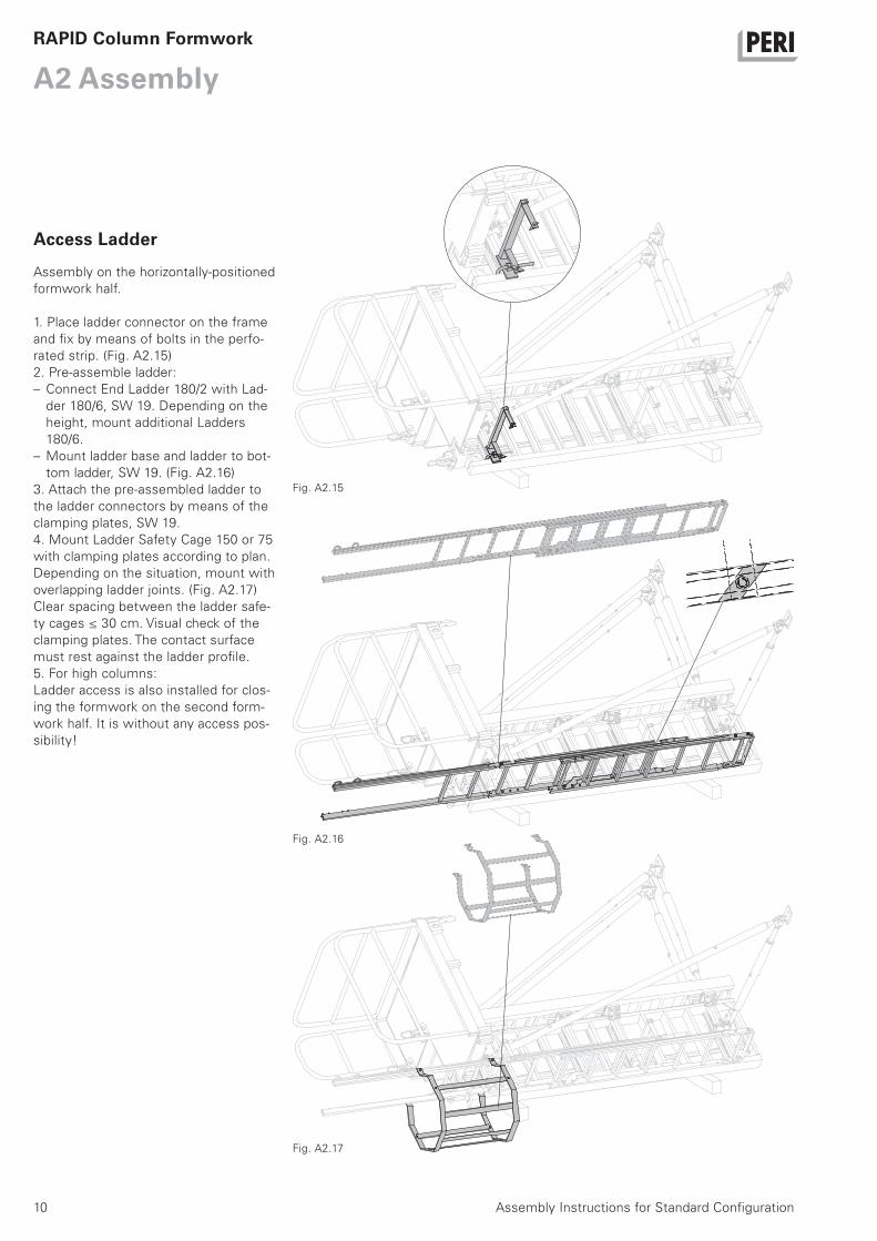
1. Place ladder connector on the frame
and fix by means of bolts in the perfo-
rated strip. (Fig. A2.15)
2. Pre-assemble ladder:
– Connect End Ladder 180/2 with Lad-
der 180/6, SW 19. Depending on the
height, mount additional Ladders
180/6.
– Mount ladder base and ladder to bot-
tom ladder, SW 19. (Fig. A2.16)
3. Attach the pre-assembled ladder to
the ladder connectors by means of the
clamping plates, SW 19.
4. Mount Ladder Safety Cage 150 or 75
with clamping plates according to plan.
Depending on the situation, mount with
overlapping ladder joints. (Fig. A2.17)
Clear spacing between the ladder safe-
ty cages ≤ 30 cm. Visual check of the
clamping plates. The contact surface
must rest against the ladder profile.
5. For high columns:
Ladder access is also installed for clos-
ing the formwork on the second form-
work half. It is without any access pos-
sibility!
Fig. A2.15
Fig. A2.16
Fig. A2.17
Access Ladder
11Assembly Instructions for Standard Configuration
A2 AssemblyRAPID Column Formwork
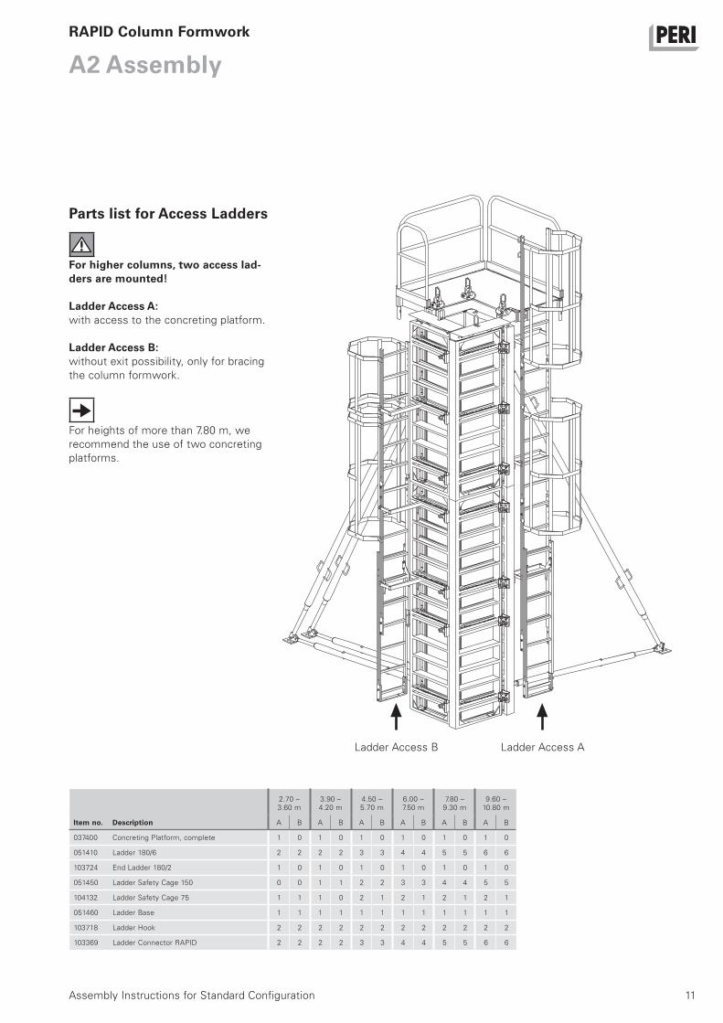
For higher columns, two access lad-ders are mounted!
Ladder Access A:with access to the concreting platform.
Ladder Access B:without exit possibility, only for bracing
the column formwork.
For heights of more than 7.80 m, we
recommend the use of two concreting
platforms.
Ladder Access B Ladder Access A
Item no. Description
2.70 –3.60 m
3.90 –4.20 m
4.50 –5.70 m
6.00 –7.50 m
7.80 –9.30 m
9.60 –10.80 m
A B A B A B A B A B A B
037400 Concreting Platform, complete 1 0 1 0 1 0 1 0 1 0 1 0
051410 Ladder 180/6 2 2 2 2 3 3 4 4 5 5 6 6
103724 End Ladder 180/2 1 0 1 0 1 0 1 0 1 0 1 0
051450 Ladder Safety Cage 150 0 0 1 1 2 2 3 3 4 4 5 5
104132 Ladder Safety Cage 75 1 1 1 0 2 1 2 1 2 1 2 1
051460 Ladder Base 1 1 1 1 1 1 1 1 1 1 1 1
103718 Ladder Hook 2 2 2 2 2 2 2 2 2 2 2 2
103369 Ladder Connector RAPID 2 2 2 2 3 3 4 4 5 5 6 6
Parts list for Access Ladders
12
A3 Shuttering
Assembly Instructions for Standard Configuration
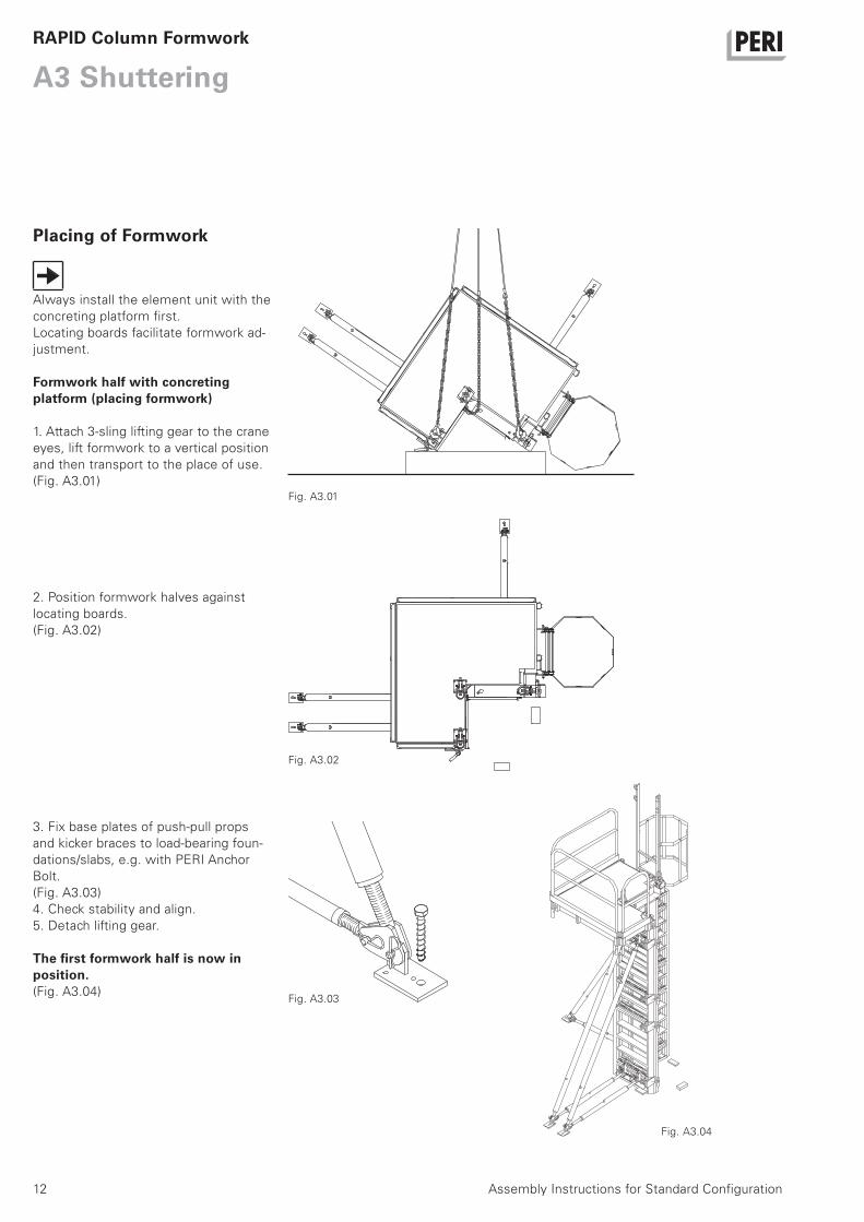
Always install the element unit with the
concreting platform first.
Locating boards facilitate formwork ad-
justment.
Formwork half with concreting platform (placing formwork)
1. Attach 3-sling lifting gear to the crane
eyes, lift formwork to a vertical position
and then transport to the place of use.
(Fig. A3.01)
2. Position formwork halves against
locating boards.
(Fig. A3.02)
3. Fix base plates of push-pull props
and kicker braces to load-bearing foun-
dations/slabs, e.g. with PERI Anchor
Bolt.
(Fig. A3.03)
4. Check stability and align.
5. Detach lifting gear.
The first formwork half is now in position.(Fig. A3.04)
RAPID Column Formwork
Fig. A3.01
Fig. A3.02
Fig. A3.03
Fig. A3.04
Placing of Formwork
13Assembly Instructions for Standard Configuration
A3 ShutteringRAPID Column Formwork
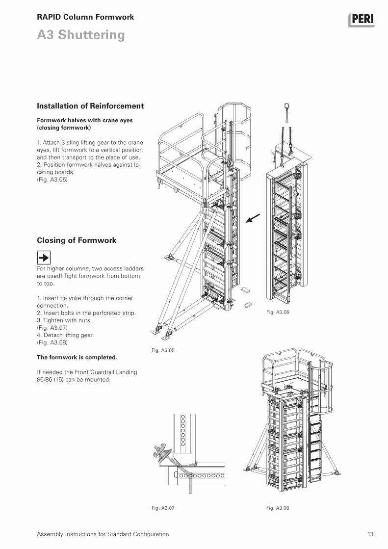
Formwork halves with crane eyes (closing formwork)
1. Attach 3-sling lifting gear to the crane
eyes, lift formwork to a vertical position
and then transport to the place of use.
2. Position formwork halves against lo-
cating boards.
(Fig. A3.05)
For higher columns, two access ladders
are used! Tight formwork from bottom
to top.
1. Insert tie yoke through the corner
connection.
2. Insert bolts in the perforated strip.
3. Tighten with nuts.
(Fig. A3.07)
4. Detach lifting gear.
(Fig. A3.08)
The formwork is completed.
If needed the Front Guardrail Landing
86/86 (15) can be mounted.
Fig. A3.05
Fig. A3.07 Fig. A3.08
Fig. A3.06
Installation of Reinforcement
Closing of Formwork

14
A4 Striking, Moving
Assembly Instructions for Standard Configuration
Push-pull props, concreting platform
and ladder access remain attached.
Open formwork from top to bottom.
The corner connections remain on the
column frame (no individual compo-
nents).
Formwork half without push-pull props
1. Attach lifting gear to the non-support-
ed formwork half and tension.
2. Divide up corner connections bew-
teen the formwork halves: pull bolts
and remove tie yoke. (Fig. A4.01)
Use second ladder access.
3. Place formwork half in position for
cleaning.
Formwork half with push-pull props
1. Attach lifting gear to the crane eyes
of the concreting platform.
2. Remove base plates of the push-pull
props and kicker braces from the
ground.
3. Place formwork half in position for
cleaning and secure. (Fig. A4.01)
RAPID Column Formwork
Shuttered.
Struck.
Fig. A4.01
Striking and Moving
15Assembly Instructions for Standard Configuration
A5 Oversized Column Cross-Sections
Table of required Alignment Couplers BFD and Steel Waler SRZ
RAPID Column Formwork
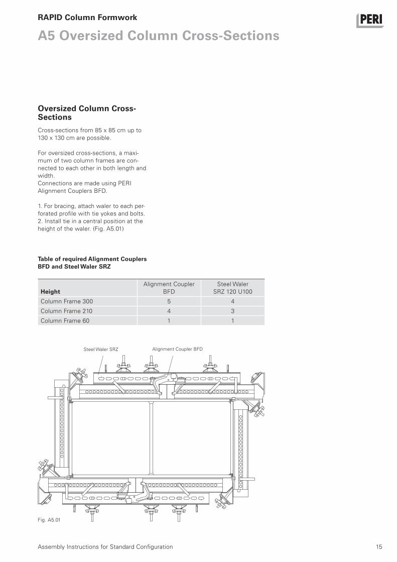
Cross-sections from 85 x 85 cm up to
130 x 130 cm are possible.
For oversized cross-sections, a maxi-
mum of two column frames are con-
nected to each other in both length and
width.
Connections are made using PERI
Alignment Couplers BFD.
1. For bracing, attach waler to each per-
forated profile with tie yokes and bolts.
2. Install tie in a central position at the
height of the waler. (Fig. A5.01)
Fig. A5.01
HeightAlignment Coupler
BFD
Steel Waler
SRZ 120 U100
Column Frame 300 5 4
Column Frame 210 4 3
Column Frame 60 1 1
Steel Waler SRZ Alignment Coupler BFD
Oversized Column Cross-Sections
300 210 60
2.10 - 1 -
2.70 1 1
3.00 1 - -
3.30 - 1 2
3.60 1 - 1
3.90 - 1 3
4.20 - 2 -
4.50 - 1 4
4.80 - 2 1
5.10 1 1 -
5.40 - 2 2
5.70 1 1 1
6.00 2 - -
6.30 1 1 2
6.60 2 - 1
6.90 1 1 3
7.20 2 - 2
7.50 1 1 4
7.80 2 - 3
8.10 2 1 -
16
A6 Height Adjustment
Assembly Instructions for Standard Configuration
Height adjustments in 30 cm incre-
ments are possible with three frame
heights.
The column frames are connected using
Bolts M20 x 50, SW 30, in the topmost
column struts.
RAPID Column Formwork
Height Adjustment up to 8.10 m Required number of column framesHeight of
formwork [m]
17Assembly Instructions for Standard Configuration
RAPID Column Formwork
18
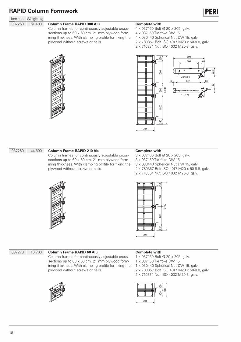
Item no. Weight kg
RAPID Column Formwork
037250 61,400 Column Frame RAPID 300 AluColumn frames for continuously adjustable cross-
sections up to 60 x 60 cm. 21 mm plywood form-
ining thickness. With clamping profile for fixing the
plywood without screws or nails.
Complete with4 x 037160 Bolt Ø 20 x 205, galv.
4 x 037150 Tie Yoke DW 15
4 x 030440 Spherical Nut DW 15, galv.
2 x 780357 Bolt ISO 4017 M20 x 50-8.8, galv.
2 x 710334 Nut ISO 4032 M20-8, galv.
250 800
500 64
238
60 654 80
3000
794
Ø21
M 20x50
1000
500
1000
250
120
037260 44,800 Column Frame RAPID 210 AluColumn frames for continuously adjustable cross-
sections up to 60 x 60 cm. 21 mm plywood form-
ining thickness. With clamping profile for fixing the
plywood without screws or nails.
Complete with3 x 037160 Bolt Ø 20 x 205, galv.
3 x 037150 Tie Yoke DW 15
3 x 030440 Spherical Nut DW 15, galv.
2 x 780357 Bolt ISO 4017 M20 x 50-8.8, galv.
2 x 710334 Nut ISO 4032 M20-8, galv.
250
800
800
250
2100
794
037270 16,700 Column Frame RAPID 60 AluColumn frames for continuously adjustable cross-
sections up to 60 x 60 cm. 21 mm plywood form-
ining thickness. With clamping profile for fixing the
plywood without screws or nails.
Complete with1 x 037160 Bolt Ø 20 x 205, galv.
1 x 037150 Tie Yoke DW 15
1 x 030440 Spherical Nut DW 15, galv.
2 x 780357 Bolt ISO 4017 M20 x 50-8.8, galv.
2 x 710334 Nut ISO 4032 M20-8, galv.
300
300 60
0
794
19
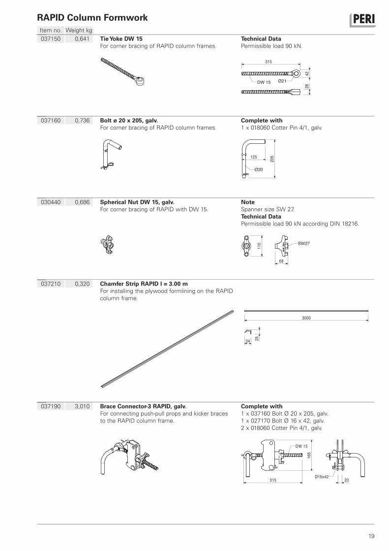
Item no. Weight kg
RAPID Column Formwork
037150 0,641 Tie Yoke DW 15For corner bracing of RAPID column frames.
Technical DataPermissible load 90 kN.
315
4228
Ø21DW 15
037160 0,736 Bolt ø 20 x 205, galv.For corner bracing of RAPID column frames.
Complete with1 x 018060 Cotter Pin 4/1, galv.
205125
Ø20
030440 0,686 Spherical Nut DW 15, galv.For corner bracing of RAPID with DW 15.
NoteSpanner size SW 27.
Technical DataPermissible load 90 kN according DIN 18216.
SW27
110
68
037210 0,320 Chamfer Strip RAPID l = 3.00 mFor installing the plywood formlining on the RAPID
column frame.
3000
34 25
037190 3,010 Brace Connector-3 RAPID, galv.For connecting push-pull props and kicker braces
to the RAPID column frame.
Complete with1 x 037160 Bolt Ø 20 x 205, galv.
1 x 027170 Bolt Ø 16 x 42, galv.
2 x 018060 Cotter Pin 4/1, galv.
165
315
DW 15
Ø16x4220
20
Item no. Weight kg
RAPID Column Formwork
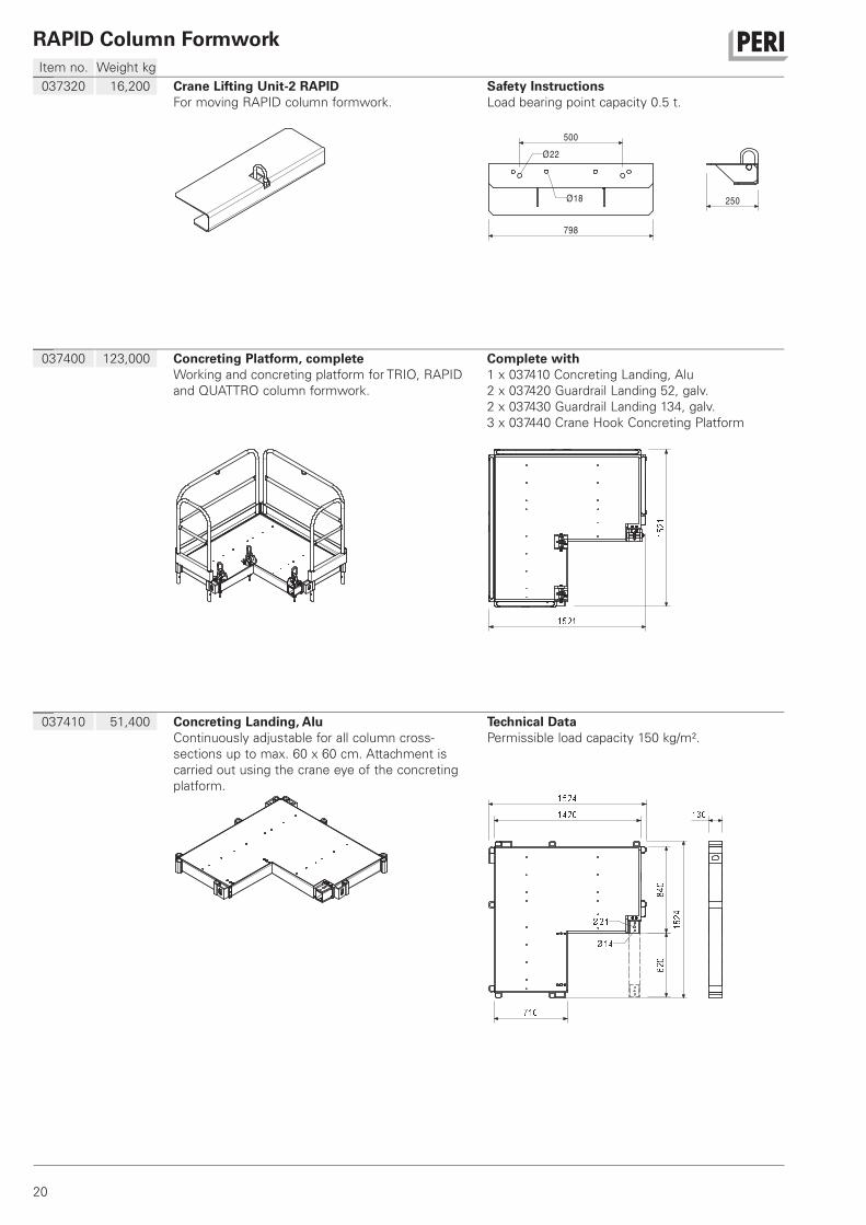
037320 16,200 Crane Lifting Unit-2 RAPIDFor moving RAPID column formwork.
Safety InstructionsLoad bearing point capacity 0.5 t.
798
Ø18
Ø22
500
250
037400 123,000 Concreting Platform, completeWorking and concreting platform for TRIO, RAPID
and QUATTRO column formwork.
Complete with1 x 037410 Concreting Landing, Alu
2 x 037420 Guardrail Landing 52, galv.
2 x 037430 Guardrail Landing 134, galv.
3 x 037440 Crane Hook Concreting Platform
037410 51,400 Concreting Landing, AluContinuously adjustable for all column cross-
sections up to max. 60 x 60 cm. Attachment is
carried out using the crane eye of the concreting
platform.
Technical DataPermissible load capacity 150 kg/m².
21
Item no. Weight kg
RAPID Column Formwork
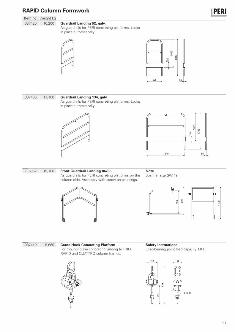
037420 10,200 Guardrail Landing 52, galv.As guardrails for PERI concreting platforms. Locks
in place automatically.
1005
1305
525
150
50
037430 17,100 Guardrail Landing 134, galv.As guardrails for PERI concreting platforms. Locks
in place automatically.
1340 50
150
1005
1305
115352 15,100 Front Guardrail Landing 86/86As guardrails for PERI concreting platforms on the
column side. Assembly with screw-on couplings.
NoteSpanner size SW 19.
824
115099
4
037440 5,660 Crane Hook Concreting PlatformFor mounting the concreting landing to TRIO,
RAPID and QUATTRO column frames.
Safety InstructionsLoad-bearing point load capacity 1.0 t.
22
Item no. Weight kg
RAPID Column Formwork
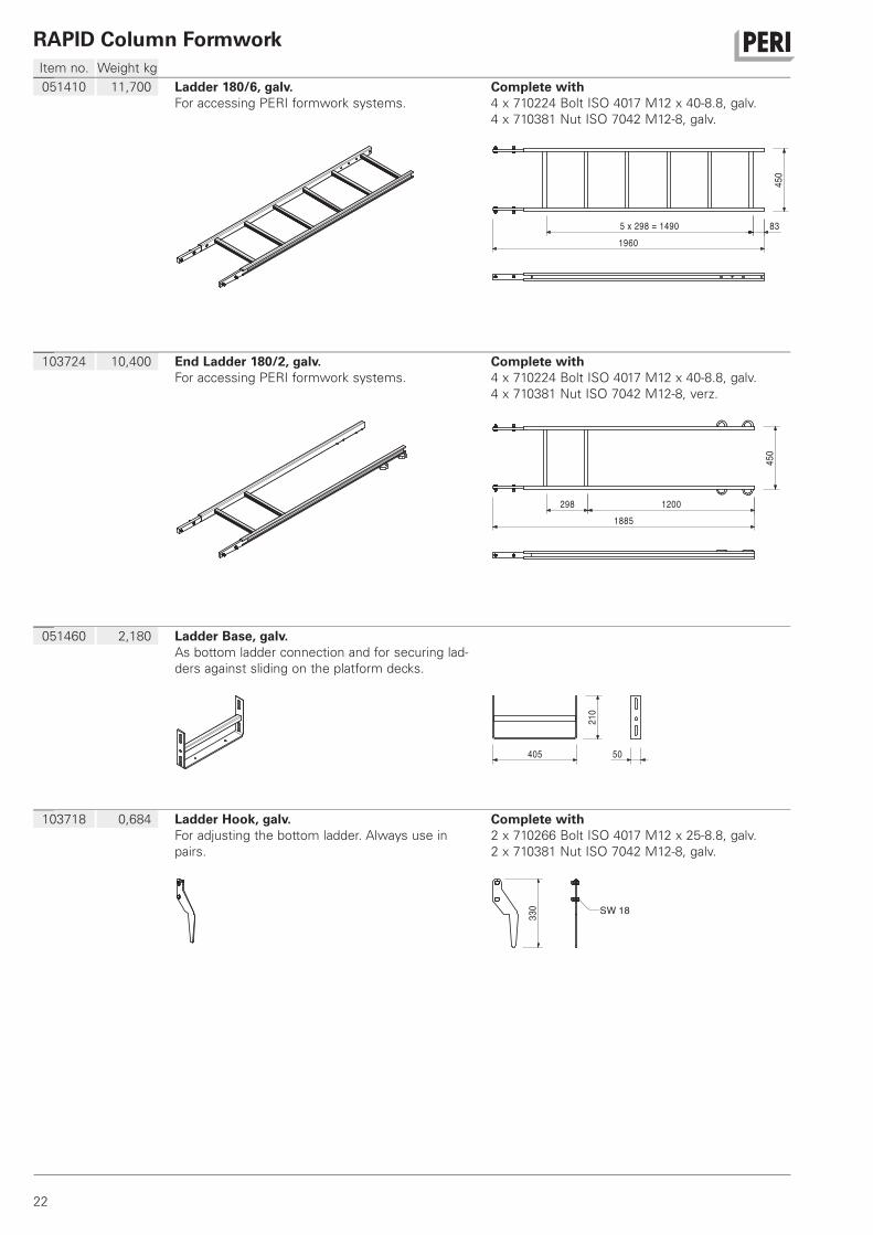
051410 11,700 Ladder 180/6, galv.For accessing PERI formwork systems.
Complete with4 x 710224 Bolt ISO 4017 M12 x 40-8.8, galv.
4 x 710381 Nut ISO 7042 M12-8, galv.
14905 x 298 = 83
1960
450
103724 10,400 End Ladder 180/2, galv.For accessing PERI formwork systems.
Complete with4 x 710224 Bolt ISO 4017 M12 x 40-8.8, galv.
4 x 710381 Nut ISO 7042 M12-8, verz.
298 1200
1885
450
051460 2,180 Ladder Base, galv.As bottom ladder connection and for securing lad-
ders against sliding on the platform decks.
405
210
50
103718 0,684 Ladder Hook, galv.For adjusting the bottom ladder. Always use in
pairs.
Complete with2 x 710266 Bolt ISO 4017 M12 x 25-8.8, galv.
2 x 710381 Nut ISO 7042 M12-8, galv.
330 SW 18
23
Item no. Weight kg
RAPID Column Formwork
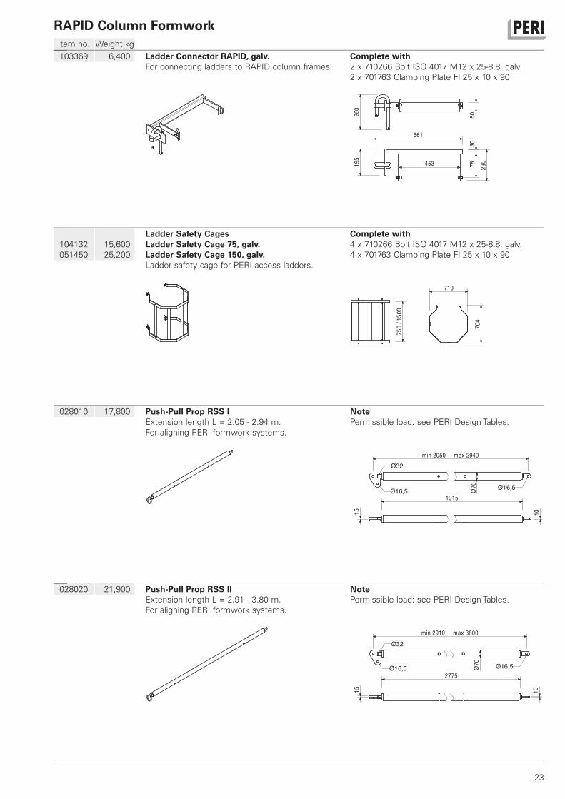
103369 6,400 Ladder Connector RAPID, galv.For connecting ladders to RAPID column frames.
Complete with2 x 710266 Bolt ISO 4017 M12 x 25-8.8, galv.
2 x 701763 Clamping Plate Fl 25 x 10 x 90
230
50
195
260
178
30
453
661
104132
051450
15,600
25,200
Ladder Safety CagesLadder Safety Cage 75, galv.Ladder Safety Cage 150, galv.Ladder safety cage for PERI access ladders.
Complete with4 x 710266 Bolt ISO 4017 M12 x 25-8.8, galv.
4 x 701763 Clamping Plate Fl 25 x 10 x 90
750
/150
0
710
704
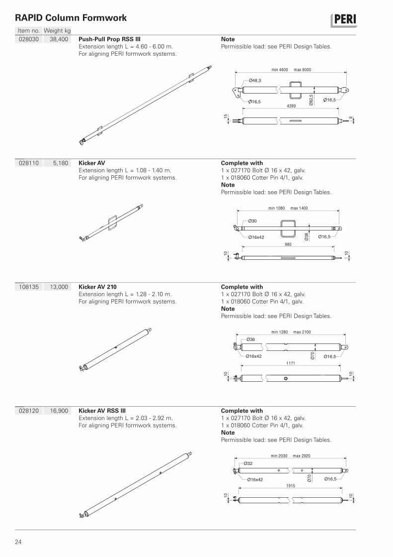
028010 17,800 Push-Pull Prop RSS IExtension length L = 2.05 - 2.94 m.
For aligning PERI formwork systems.
NotePermissible load: see PERI Design Tables.
2050min max 2940
1915Ø16,5
Ø16,5
1015
Ø3270
Ø
028020 21,900 Push-Pull Prop RSS IIExtension length L = 2.91 - 3.80 m.
For aligning PERI formwork systems.
NotePermissible load: see PERI Design Tables.
min 2910 max 3800
Ø16,5Ø16,52775
Ø32
10
70Ø
15
24
Item no. Weight kg
RAPID Column Formwork
028030 38,400 Push-Pull Prop RSS IIIExtension length L = 4.60 - 6.00 m.
For aligning PERI formwork systems.
NotePermissible load: see PERI Design Tables.
min 4600 max 6000
439916,5 16,5
Ø48,3
915
82,5
Ø
028110 5,180 Kicker AVExtension length L = 1.08 - 1.40 m.
For aligning PERI formwork systems.
Complete with1 x 027170 Bolt Ø 16 x 42, galv.
1 x 018060 Cotter Pin 4/1, galv.
NotePermissible load: see PERI Design Tables.
min 1080 max 1400
980
Ø16x42 Ø16,5
1010Ø30
38Ø
108135 13,000 Kicker AV 210Extension length L = 1.28 - 2.10 m.
For aligning PERI formwork systems.
Complete with1 x 027170 Bolt Ø 16 x 42, galv.
1 x 018060 Cotter Pin 4/1, galv.
NotePermissible load: see PERI Design Tables.
min 1280 max 2100
1171
Ø16x42 Ø16,51010
Ø36
70Ø
028120 16,900 Kicker AV RSS IIIExtension length L = 2.03 - 2.92 m.
For aligning PERI formwork systems.
Complete with1 x 027170 Bolt Ø 16 x 42, galv.
1 x 018060 Cotter Pin 4/1, galv.
NotePermissible load: see PERI Design Tables.
min 2030 max 2920
1915Ø16x42 Ø16,5
Ø32
10 10
70Ø
25
Item no. Weight kg
RAPID Column Formwork
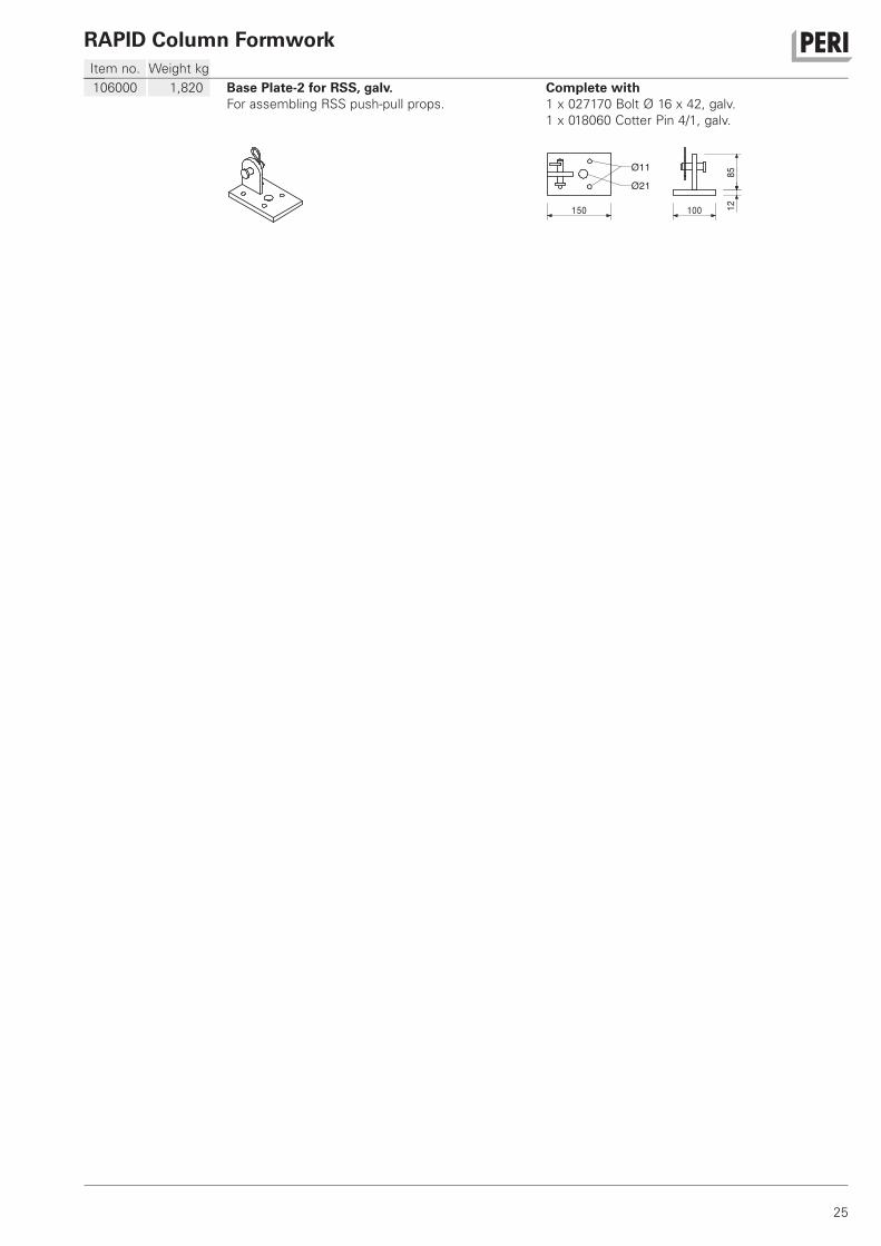
106000 1,820 Base Plate-2 for RSS, galv.For assembling RSS push-pull props.
Complete with1 x 027170 Bolt Ø 16 x 42, galv.
1 x 018060 Cotter Pin 4/1, galv.
150
Ø21
Ø11
100 1285
2
1
3
4
5
6
9
11
12
1316
17
18
19
20
22
21
24
2829
30
32
33
34
38
41
42
46
48
52
44
53
61
26
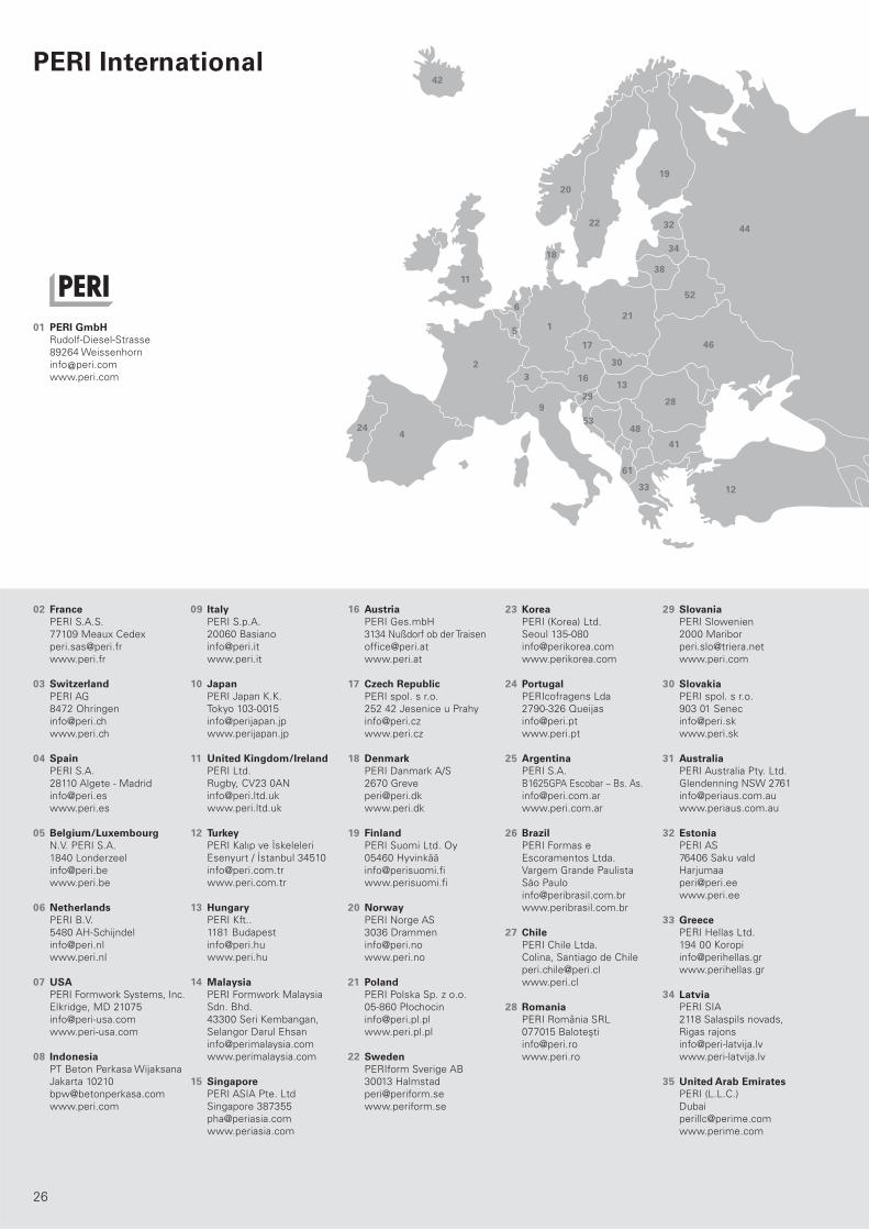
02 PERI S.A.S.
77109 Meaux Cedex
www.peri.fr
03 PERI AG
8472 Ohringen
www.peri.ch
04 PERI S.A.
28110 Algete - Madrid
www.peri.es
05 N.V. PERI S.A.
1840 Londerzeel
www.peri.be
06 PERI B.V.
5480 AH-Schijndel
www.peri.nl
07 PERI Formwork Systems, Inc.
Elkridge, MD 21075
www.peri-usa.com
08 PT Beton Perkasa Wijaksana
Jakarta 10210
www.peri.com
09 PERI S.p.A.
20060 Basiano
www.peri.it
10 PERI Japan K.K.
Tokyo 103-0015
www.perijapan.jp
11 PERI Ltd.
Rugby, CV23 0AN
www.peri.ltd.uk
12 PERI Kalıp ve İskeleleri
Esenyurt / İstanbul 34510
www.peri.com.tr
13 PERI Kft..
1181 Budapest
www.peri.hu
14 PERI Formwork Malaysia
Sdn. Bhd.
43300 Seri Kembangan,
Selangor Darul Ehsan
www.perimalaysia.com
15 PERI ASIA Pte. Ltd
Singapore 387355
www.periasia.com
16 PERI Ges.mbH
3134 Nußdorf ob der Traisen
www.peri.at
17 PERI spol. s r.o.
252 42 Jesenice u Prahy
www.peri.cz
18 PERI Danmark A/S
2670 Greve
www.peri.dk
19 PERI Suomi Ltd. Oy
05460 Hyvinkää
www.perisuomi.fi
20 PERI Norge AS
3036 Drammen
www.peri.no
21 PERI Polska Sp. z o.o.
05-860 Płochocin
www.peri.pl.pl
22 PERIform Sverige AB
30013 Halmstad
www.periform.se
23 PERI (Korea) Ltd.
Seoul 135-080
www.perikorea.com
24 PERIcofragens Lda
2790-326 Queijas
www.peri.pt
25 PERI S.A.
B1625GPA Escobar – Bs. As.
www.peri.com.ar
26 PERI Formas e
Escoramentos Ltda.
Vargem Grande Paulista
São Paulo
www.peribrasil.com.br
27 PERI Chile Ltda.
Colina, Santiago de Chile
www.peri.cl
28 PERI România SRL
077015 Baloteşti
www.peri.ro
29 PERI Slowenien
2000 Maribor
www.peri.com
30 PERI spol. s r.o.
903 01 Senec
www.peri.sk
31 PERI Australia Pty. Ltd.
Glendenning NSW 2761
www.periaus.com.au
32 PERI AS
76406 Saku vald
Harjumaa
www.peri.ee
33 PERI Hellas Ltd.
194 00 Koropi
www.perihellas.gr
34 PERI SIA
2118 Salaspils novads,
Rigas rajons
www.peri-latvija.lv
35 PERI (L.L.C.)
Dubai
www.perime.com
01 PERI GmbH Rudolf-Diesel-Strasse
89264 Weissenhorn
www.peri.com
France
Switzerland
Spain
Belgium/Luxembourg
Netherlands
USA
Indonesia
Italy
Japan
United Kingdom/Ireland
Turkey
Hungary
Malaysia
Singapore
Austria
Czech Republic
Denmark
Finland
Norway
Poland
Sweden
Korea
Portugal
Argentina
Brazil
Chile
Romania
Slovania
Slovakia
Australia
Estonia
Greece
Latvia
United Arab Emirates
PERI International

8
10
1415
23
31
35
3739 40
43
44
45
47
50 51
54
595558
5760 56
65
64
66
7
25
26
27
36
49
62
63
27
36 PERI Formwork Systems, Inc.
Bolton, ON – L7E 1K1
www.peri.ca
37 Lebanon Representative Office
Jdeideh
www.peri.de
38 PERI UAB
02300 Vilnius
www.peri.lt
39 PERI S.A.
Tanger
www.peri.com
40 PERI Formwork
Engineering Ltd
Petach Tikva, 49002
www.peri.co.il
41 PERI Bulgaria EOOD
1839 Sofia
www.peri.bg
42 Armar ehf.
220 Hafnarfjörður
www.armar.is
43 TOO PERI Kazakhstan
050014 Almaty
www.peri.kz
44 OOO PERI
142407, Noginsk District
www.peri.ru
45 Wiehahn Formwork and
Scaffolding (Pty) Ltd.
7600 Stellenbosch
www.wiehahn.co.za
46 TOW PERI Ukraina
07400 Brovary
www.peri.ua
47 Egypt Branch Office
11361 Heliopolis / Cairo
www.peri.com.eg
48 PERI Oplate d.o.o.
11272 Dobanovci
www.peri.rs
49 PERI Cimbras y Andamios,
S.A. de C.V.
Estado de México,
www.peri.com.mx
50 PERI Kalıp ve İskeleleri
Baku
www.peri.com.tr
51
PERI Kalıp ve İskeleleri
Aşgabat
www.peri.com.tr
52 PERI Belarus
220030 Minsk
www.peri.com
53 PERI oplate i skele d.o.o.
10 250 Donji Stupnik/
Zagreb
www.peri.com.hr
54 PERI GmbH
Iran Branch Office
Tehran
www.peri.ir
55 PERI (India) Pvt Ltd
Mumbai – 400064
www.peri.in
56 PERI GmbH - Jordan
11947 Amman
www.peri.com
57 PERI Kuwait
13011 Kuwait
www.peri.com
58 PERI Engineering
Division of Jamjoom
Consult Saudi Arabia
21463 Jeddah
www.peri.com.sa
59 PERI Qatar LLC
P.O.Box: 31295 - Doha
www.periqatar.com
60 Société PERI S.A.S.
Kouba - Alger
www.peri.fr
61
PERI Sh.p.k.
Tirane
www.peri.com.tr
62 PERI Peruana SAC
Chorrillos, Lima
www.peri.com.pe
63 PERI Panama Inc.
0832-00155 Panama City
www.peri.com.pa
64 PERIcofragens, Lda.
Luanda
www.peri.pt
65 Heights Access Nigeria Ltd.
Victoria Island, Lagos
www. heightsaccessng.com
66 PERI (L.L.C.)
Muscat
www.perime.com
Canada
Lebanon
Lithuania
Morocco
Israel
Bulgaria
Iceland
Kazakhstan
Russian Federation
South Africa
Ukraine
Egypt
Serbia
Mexico
Azerbaijan
Turkmenistan
Belorussia
Croatia
Iran
India
Jordan
Kuwait
Saudi Arabia
Qatar
Algeria
Albania
Peru
Panama
Angola
Nigeria
Oman
D e
01/2
011
3m
a A
rt.-
Nr.:
792216
© C
opyright
by P
ER
I G
mbH
Wall FormworkPanel Formwork
Girder Formwork
Circular Formwork
Facade Formwork
Brace Frame
Column FormworkSquare
Rectangular
Circular
Slab FormworkPanel Formwork
Beam Grid Formwork
Girder Formwork
Slab Table
Beam Formwork
Shoring SystemsSteel Slab Props
Aluminium Slab Props
Tower Systems
Heavy-Duty Props
Climbing SystemsClimbing Scaffold
Self-Climbing System
Climbing Protection Panel
Platform Systems
Scaffold, Stairways, Working PlatformsFacade Scaffold
Working Platform
Weather Protection Roof
Stairway Access
Bridge and Tunnel FormworkCantilevered Parapet Carriage
Cantilevered Parapet Platform
Engineer’s Construction Kit
ServicesFormwork Assembly
Cleaning / Repairs
Formwork Planning
Software
Statics
Special Constructions
Additional SystemsSafety Systems
Plywood
Formwork Girders
Stopend Systems
Pallets
Transportation Containers
PERI GmbHFormwork Scaffolding EngineeringP.O. Box 1264
89259 Weissenhorn
Germany
Tel. +49 (0)7309.950-0
Fax +49 (0)7309.951-0
www.peri.com
PERI Product Range