Embed Size (px)
Citation preview

RAPID PROTOTYPING TECHNOLOGIES, APPLICATIONS AND PART DEPOSITION PLANNING
Pulak M. Pandey Department of Mechanical Engineering
Indian Institute of Technology Delhi Email: [email protected]
1. INTRODUCTION Prototyping or model making is one of the important steps to finalize a product design. It helps in conceptualization of a design. Before the start of full production a prototype is usually fabricated and tested. Manual prototyping by a skilled craftsman has been an age-old practice for many centuries. Second phase of prototyping started around mid-1970s, when a soft prototype modeled by 3D curves and surfaces could be stressed in virtual environment, simulated and tested with exact material and other properties. Third and the latest trend of prototyping, i.e., Rapid Prototyping (RP) by layer-by-layer material deposition, started during early 1980s with the enormous growth in Computer Aided Design and Manufacturing (CAD/CAM) technologies when almost unambiguous solid models with knitted information of edges and surfaces could define a product and also manufacture it by CNC machining. The historical development of RP and related technologies is presented in table 1.
Year of inception Technology 1770 Mechanization 1946 First computer 1952 First Numerical Control (NC) machine tool 1960 First commercial laser 1961 First commercial Robot 1963 First interactive graphics system (early version of Computer
Aided Design) 1988 First commercial Rapid Prototyping system
Table 1: Historical development of Rapid Prototyping and related technologies (after Chua and Leong, 2000)
2. BASIC PRINCIPLE OF RAPID PROTOTYPING PROCESSES RP process belong to the generative (or additive) production processes unlike subtractive or forming processes such as lathing, milling, grinding or coining etc. in which form is shaped by material removal or plastic deformation. In all commercial RP processes, the part is fabricated by deposition of layers contoured in a (x-y) plane two dimensionally. The third dimension (z) results from single layers being stacked up on top of each other, but not as a continuous z-coordinate. Therefore, the prototypes are very exact on the x-y plane but have stair-stepping effect in z-direction. If model is deposited with very fine layers, i.e., smaller z-stepping, model looks like original. RP can be classified into two fundamental process steps namely generation of mathematical layer information and

2
generation of physical layer model. Typical process chain of various RP systems is shown in figure 1.
Figure 1: RP process chain showing fundamental process steps
It can be seen from figure 1 that process starts with 3D modeling of the product and then STL file is exported by tessellating the geometric 3D model. In tessellation various surfaces of a CAD model are piecewise approximated by a series of triangles (figure 2) and co-ordinate of vertices of triangles and their surface normals are listed. The number and size of triangles are decided by facet deviation or chordal error as shown in figure 2. These STL files are checked for defects like flip triangles, missing facets, overlapping facets, dangling edges or faces etc. and are repaired if found faulty. Defect free STL files are used as an input to various slicing softwares. At this stage choice of part deposition orientation is the most important factor as part building time, surface quality, amount of support structures, cost etc. are influenced. Once part deposition orientation is decided and slice thickness is selected, tessellated model is sliced and the generated data in standard data formats like SLC (stereolithography contour) or CLI (common layer interface) is stored. This information is used to move to step 2, i.e., generation of physical model. The software that operates RP systems generates laser-scanning paths (in processes like Stereolithography, Selective Laser Sintering etc.) or material deposition paths (in processes like Fused Deposition Modeling). This step is different for different processes and depends on the basic deposition principle used in RP machine. Information computed here is used to deposit the part layer-by-layer on RP system platform. The generalized data flow in RP is given in figure 3.

3
3D CAD 2D CAD Drawing / Manual outline/
Lattice Data
Point cloud data Data acquired from MRI or CT scan
Reverse Engineering 3D reconstruction 2.5D reconstruction
3D CAD
STL (3D) Layer information, SCL or CLI
Geometric data
Auxiliary geometry (supports etc.)
Process parameters Machine parameters
Machine data set
Specification of machine layer information
Figure 2: Tessellation of a typical surface of CAD model (after Pandey et al. 2003b)
The final step in the process chain is the post-processing task. At this stage, generally some manual operations are necessary therefore skilled operator is required. In cleaning, excess elements adhered with the part or support structures are removed. Sometimes the surface of the model is finished by sanding, polishing or painting for better surface finish or aesthetic appearance. Prototype is then tested or verified and suggested engineering changes are once again incorporated during the solid modeling stage.
Figure 3: Generalized illustration of data flow in RP (after Gebhardt, 2003)

4
3. RAPID PROTOTYPING PROCESSES The professional literature in RP contains different ways of classifying RP processes. However, one representation based on German standard of production processes classifies RP processes according to state of aggregation of their original material and is given in figure 4.
Figure 4: Classification of RP processes (after Gebhardt, 2003)
Here, few important RP processes namely Stereolithography (SL), Selective Laser Sintering (SLS), Fused Deposition Modeling (FDM) and Laminated Object Manufacturing (LOM) are described.
3.1. Stereolithography In this process photosensitive liquid resin which forms a solid polymer when exposed to ultraviolet light is used as a fundamental concept. Due to the absorption and scattering of beam, the reaction only takes place near the surface and voxels of solid polymeric resin are formed. A SL machine consists of a build platform (substrate), which is mounted in a vat of resin and a UV Helium-Cadmium or Argon ion laser. The laser scans the first layer and platform is then lowered equal to one slice thickness and left for short time (dip-delay) so that liquid polymer settles to a flat and even surface and inhibit bubble formation. The new
Generative Manufacturing Processes
Melting and re-solidification
Selective Laser Sintering
Solidification by binder
3D Printing
Solid
Cutting and gluing
Layer Laminated Manufacturing
Cutting and polymerization
Solid Foil Polymerization
Wire
One or multi-component powder
Foil
Melting and re-solidification
Fused Layer Modeling
Ballistic Part Manufacturing
Paste
Polymerization Paste
Polymerization Process
Liquid
Polymerization
Gaseous
Chemical reaction LCVD
Heat Thermal
Polymerization
Lamp Solid
Ground Curing
Light of one frequency
Laser beam Stereolithography
Holography Holographic Interference
Solidification

5
slice is then scanned. Schematic diagram of a typical Stereolithography apparatus is shown in figure 5.
In new SL systems, a blade spreads resin on the part as the blade traverses the vat. This ensures smoother surface and reduced recoating time. It also reduces trapped volumes which are sometimes formed due to excessive polymerization at the ends of the slices and an island of liquid resin having thickness more than slice thickness is formed (Pham and Demov, 2001). Once the complete part is deposited, it is removed from the vat and then excess resin is drained. It may take long time due to high viscosity of liquid resin. The green part is then post-cured in an UV oven after removing support structures.
Figure 5: Stereolithography (after Pham and Demov, 2001)
Overhangs or cantilever walls need support structures as a green layer has relatively low stability and strength. These overhangs etc. are supported if they exceed a certain size or angle, i.e., build orientation. The main functions of these structures are to support projecting parts and also to pull other parts down which due to shrinkage tends to curl up (Gebhardt, 2003). These support structures are generated during data processing and due to these data grows heavily specially with STL files, as cuboid shaped support element need information about at least twelve triangles. A solid support is very difficult to remove later and may damage the model. Therefore a new support structure called fine point was developed by 3D Systems (figure 6) and is company s trademark.
Build strategies have been developed to increase build speed and to decrease amount of resin by depositing the parts with a higher proportion of hollow volume. These strategies are devised as these models are used for making cavities for precision castings. Here walls are designed hollow connected by rod-type bridging elements and skin is introduced that close the model at the top and the bottom. These models require openings to drain out uncured resin.

6
Figure 6: Fine point structure for Stereolithography (after Gebhardt, 2003)
3.2. Selective Laser Sintering In Selective Laser Sintering (SLS) process, fine polymeric powder like polystyrene, polycarbonate or polyamide etc. (20 to 100 micrometer diameter) is spread on the substrate using a roller. Before starting CO2 laser scanning for sintering of a slice the temperature of the entire bed is raised just below its melting point by infrared heating in order to minimize thermal distortion (curling) and facilitate fusion to the previous layer. The laser is modulated in such away that only those grains, which are in direct contact with the beam, are affected (Pham and Demov, 2001). Once laser scanning cures a slice, bed is lowered and powder feed chamber is raised so that a covering of powder can be spread evenly over the build area by counter rotating roller. In this process support structures are not required as the unsintered powder remains at the places of support structure. It is cleaned away and can be recycled once the model is complete. The schematic diagram of a typical SLS apparatus is given in figure 7.
3.3. Fused Deposition Modeling In Fused Deposition Modeling (FDM) process a movable (x-y movement) nozzle on to a substrate deposits thread of molten polymeric material. The build material is heated slightly above (approximately 0.5 C) its melting temperature so that it solidifies within a very short time (approximately 0.1 s) after extrusion and cold-welds to the previous layer as shown in figure 8. Various important factors need to be considered and are steady nozzle and material extrusion rates, addition of support structures for overhanging features and speed of the nozzle head, which affects the slice thickness. More recent FDM systems include two nozzles, one for part material and other for support material. The support material is relatively of poor quality and can be broken easily once the complete part is deposited and is removed from substrate. In more recent FDM technology, water-soluble

7
support structure material is used. Support structure can be deposited with lesser density as compared to part density by providing air gaps between two consecutive roads.
Figure 7: Selective Laser Sintering System
Figure 8: Fused Deposition Modeling Process (after Pham and Demov, 2001)
3.4. Laminated Object Manufacturing Typical system of Laminated Object Manufacturing (LOM) has been shown in figure 9. It can be seen form the figure that the slices are cut in required contour from roll of material by using a 25-50 watt CO2 laser beam. A new slice is bonded to previously deposited slice by using a hot roller, which activates a heat sensitive adhesive. Apart from the slice unwanted material is also hatched in rectangles to facilitate its later removal but remains in place during the build to act as supports. Once one slice is completed platform can be

8
lowered and roll of material can be advanced by winding this excess onto a second roller until a fresh area of the sheet lies over the part. After completion of the part they are sealed with a urethane lacquer, silicone fluid or epoxy resin to prevent later distortion of the paper prototype through water absorption.
Figure 9: Laminated Object Manufacturing Process
In this process, materials that are relatively cheaper like paper, plastic roll etc. can be used. Parts of fiber-reinforced glass ceramics can be produced. Large models can be produced and the building speed is 5-10 times as compared to other RP processes. The limitation of the process included fabrication of hollow models with undercuts and reentrant features. Large amount of scrap is formed. There remains danger of fire hazards and drops of the molten materials formed during the cutting also need to be removed (Pham and Demov, 2001).
9
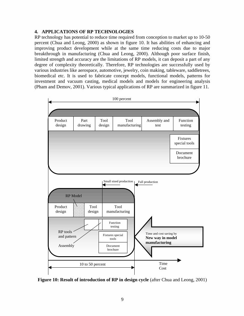
4. APPLICATIONS OF RP TECHNOLOGIES RP technology has potential to reduce time required from conception to market up to 10-50 percent (Chua and Leong, 2000) as shown in figure 10. It has abilities of enhancing and improving product development while at the same time reducing costs due to major breakthrough in manufacturing (Chua and Leong, 2000). Although poor surface finish, limited strength and accuracy are the limitations of RP models, it can deposit a part of any degree of complexity theoretically. Therefore, RP technologies are successfully used by various industries like aerospace, automotive, jewelry, coin making, tableware, saddletrees, biomedical etc. It is used to fabricate concept models, functional models, patterns for investment and vacuum casting, medical models and models for engineering analysis (Pham and Demov, 2001). Various typical applications of RP are summarized in figure 11.
Figure 10: Result of introduction of RP in design cycle (after Chua and Leong, 2001)
Product design
Part drawing
Tool design
Tool manufacturing
Assembly and test
Function testing
Fixtures special tools
Document brochure
100 percent
Product design
Tool design
Tool manufacturing
Fixtures special tools
Document brochure
Function testing
RP Model
RP tools and pattern
Assembly
10 to 50 percent
Small sized production Full production
Time Cost
Time and cost saving by
New way in model manufacturing

10
5. PART DEPOSITION PLANNING A defect less STL file is used as an input to RP software like QuickSilce or RPTools for further processing. At this stage, designer has to take an important decision about the part deposition orientation. The part deposition orientation is important because part accuracy, surface quality, building time, amount of support structures and hence cost of the part is highly influenced (Pandey et al., 2004b). In this section various factors influencing accuracy of RP parts and part deposition orientation are discussed.
5.1. Factors influencing accuracy Accuracy of a model is influenced by the errors caused during tessellation and slicing at data preparation stage. Decision of the designer about part deposition orientation also affects accuracy of the model.
Errors due to tessellation: In tessellation surfaces of a CAD model are approximated piecewise by using triangles. It is true that by reducing the size of the triangles, the deviation between the actual surfaces and approximated triangles can be reduced. In practice, resolution of the STL file is controlled by a parameter namely chordal error or facet deviation as shown in figure 2. It has also been suggested that a curve with small radius (r) should be tessellated if its radius is below a threshold radius (ro) which can be considered as one tenth of the part size, to achieve a maximum chordal error of (r/ro)
. Value of
can be set equal to 0 for no improvement and 1 for maximum improvement. Here part size is defined as the diagonal of an imaginary box drawn around the part and
is angle control value (Williams et al., 1996).
Errors due to slicing: Real error on slice plane is much more than that is felt, as shown in figure 12(a). For a spherical model Pham and Demov (2001) proposed that error due to the replacement of a circular arc with stair-steps can be defined as radius of the arc minus length up to the corresponding corner of the staircase, i.e., cusp height (figure 12 (b)). Thus maximum error (cusp height) results along z direction and is equal to slice thickness. Therefore, cusp height approaches to maximum for surfaces, which are almost parallel with the x-y plane. Maximum value of cusp height is equal to slice thickness and can be reduced by reducing it; however this results in drastic improvement in part building time. Therefore, by using slices of variable thicknesses (popularly known as adaptive slicing, as shown in figure 13), cusp height can be controlled below a certain value.
Except this, mismatching of height and missing features are two other problems resulting from the slicing. Although most of the RP systems have facility of slicing with uniform thickness only, adaptive slicing scheme, which can slice a model with better accuracy and surface finish without loosing important features must be selected. Review of various slicing schemes for RP has been done by Pandey et al. (2003a).
5.2. Part building During part deposition generally two types of errors are observed and are namely curing errors and control errors. Curing errors are due to over or under curing with respect to curing line and control errors are caused due to variation in layer thickness or scan position

11
Figure 11(a): Typical application areas of RP parts (after Chual and Leong, 2000)
(b) SL model with the resection template Silicon implant molded from a tool (after Pham and Demov, 2001)
Figure 11: Applications of RP processes
Rapid Prototyping
Finishing Processes
Cutting, milling, Lathe, boring, grinding etc.
Sand blasting Coating
Polishing Painting
Applications
Design
CAD model Verification Visualizing object Proof of concept Marketing and presenting model
Manufacturing and tooling
Plastic mold parts o Vacuum casting o Metal spraying
Casting o Sand casting o Investment casting o Die casting
EDM electrodes Master models
Engineering, Analysis and planning
Form and fit models Flow analysis Stress distribution Mock-up Diagnostic and surgical operation planning Design and fabrication of custom prosthesis and implant
Industries
Aerospace Automotive Biomedical Jewelry Coin Tableware Consumer electronic Home appliances etc.

12
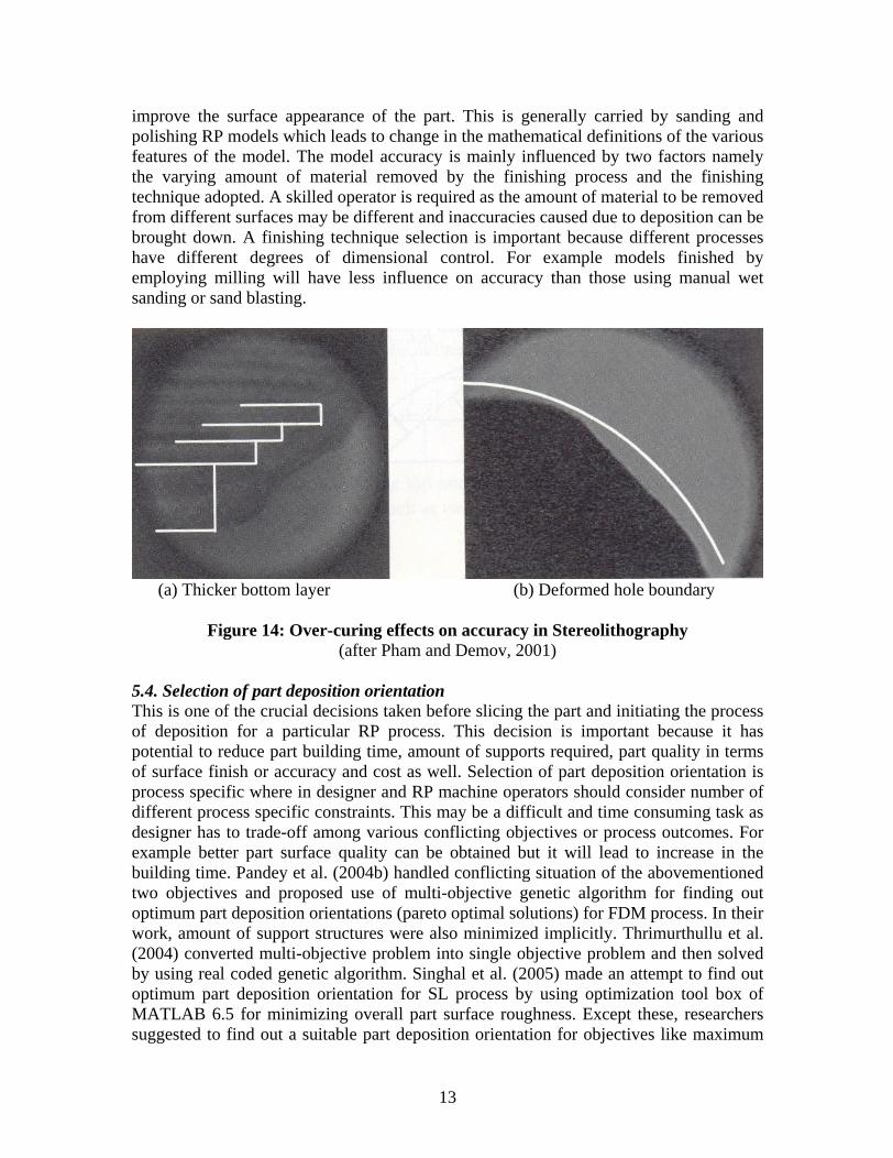
control. Figures 14 illustrate effect of over curing on part geometry and accuracy. Adjustment of chamber temperature and laser power is needed for proper curing. Calibration of the system becomes mandatory to minimize control errors. Shrinkage also causes dimensional inaccuracy and is taken care by choosing proper scaling in x, y and z directions. Polymers are also designed to have almost negligible shrinkage factors. In SL and SLS processes problem arises with downward facing layers as these layers do not have a layer underneath and are slightly thicker, which generate dimensional error. If proper care is not taken in setting temperatures, curling is frequently observed.
(a) Real error slice plane (after Pandey et al., 2003a)
(b) Error due to replacement of arcs with stair-steps, cusp height (after Pham and Demov, 2001)
Figure 12: slicing error
Figure 13: Slicing of a ball, (a) No slicing (b) Thick slicing (c) This slicing (d) Adaptive slicing (after Pham and Demov, 2001)
5.3. Part finishing Poor surface quality of RP parts is a major limitation and is primarily due to staircase effect. Surface roughness can be controlled below a predefined threshold value by using an adaptive slicing (Pandey et al., 2003b). Further, the situation can be improved by finding out a part deposition orientation that gives minimum overall average part surface roughness (Singhal et al., 2005). However, some RP applications like exhibition models, tooling or master pattern for indirect tool production etc. require additional finishing to
13
improve the surface appearance of the part. This is generally carried by sanding and polishing RP models which leads to change in the mathematical definitions of the various features of the model. The model accuracy is mainly influenced by two factors namely the varying amount of material removed by the finishing process and the finishing technique adopted. A skilled operator is required as the amount of material to be removed from different surfaces may be different and inaccuracies caused due to deposition can be brought down. A finishing technique selection is important because different processes have different degrees of dimensional control. For example models finished by employing milling will have less influence on accuracy than those using manual wet sanding or sand blasting.
(a) Thicker bottom layer (b) Deformed hole boundary
Figure 14: Over-curing effects on accuracy in Stereolithography (after Pham and Demov, 2001)
5.4. Selection of part deposition orientation This is one of the crucial decisions taken before slicing the part and initiating the process of deposition for a particular RP process. This decision is important because it has potential to reduce part building time, amount of supports required, part quality in terms of surface finish or accuracy and cost as well. Selection of part deposition orientation is process specific where in designer and RP machine operators should consider number of different process specific constraints. This may be a difficult and time consuming task as designer has to trade-off among various conflicting objectives or process outcomes. For example better part surface quality can be obtained but it will lead to increase in the building time. Pandey et al. (2004b) handled conflicting situation of the abovementioned two objectives and proposed use of multi-objective genetic algorithm for finding out optimum part deposition orientations (pareto optimal solutions) for FDM process. In their work, amount of support structures were also minimized implicitly. Thrimurthullu et al. (2004) converted multi-objective problem into single objective problem and then solved by using real coded genetic algorithm. Singhal et al. (2005) made an attempt to find out optimum part deposition orientation for SL process by using optimization tool box of MATLAB 6.5 for minimizing overall part surface roughness. Except these, researchers suggested to find out a suitable part deposition orientation for objectives like maximum

14
accuracy, minimum building time, support structure or cost. A through review of the various part deposition orientation studies has been done by Pandey et al. (2004a). Pham and Demov (2001) discussed guidelines for selection of part deposition orientation for SL and SLS processes.
6. SUMMARY This paper provides an overview of RP technology in brief and emphasizes on their ability to shorten the product design and development process. Classification of RP processes and details of few important processes is given. The description of various stages of data preparation and model building has been presented. An attempt has been made to include some important factors to be considered before starting part deposition for proper utilization of potentials of RP processes.
REFERENCES
Chua, C.K., Leong, K.F. (2000) Rapid Prototyping: Principles and Applications in Manufacturing, World Scientific.
Gebhardt, A., (2003) Rapid Prototyping, Hanser Gardner Publications, Inc., Cincinnati.
Pandey, P.M., Reddy N.V., Dhande, S.G. (2003a) Slicing Procedures in Layered Manufacturing: A Review, Rapid Prototyping Journal, 9(5), pp. 274-288.
Pandey, P.M., Reddy, N.V., Dhande, S.G. (2003b) Real Time Adaptive Slicing for Fused Deposition Modelling, International Journal of Machine Tools and Manufacture, 43(1), pp 61-71.
Pandey, P.M., Reddy, N.V., Dhande, S.G. (2004a) Part Deposition Orientation Studies in Layered Manufacturing, Proceeding of International Conference on Advanced Manufacturing Technology, pp. 907-912.
Pandey, P.M., Thrimurthullu, K., Reddy, N.V. (2004b) Optimal Part Deposition Orientation in FDM using Multi-Criteria GA, International Journal of Production Research, 42(19), pp. 4069-4089.
Pham, D.T., Dimov, S.S. (2001) Rapid Manufacturing, Springer-Verlag London Limited.
Singhal, S.K., Pandey, A.P., Pandey, P.M., Nagpal, A.K. (2005) Optimum Part Deposition Orientation in Stereolithography, Computer Aided Design and Applications, 2 (1-4).
Thrimurthullu, K., Pandey, P.M., Reddy, N.V. (2004) Part Deposition Orientation in Fused Deposition Modeling, International Journal of Machine Tools and Manufacture, 2004, 44, pp. 585-594.
Williams, R.E., Komaragiri., S.N., Melton, V.L., Bishu, R.R. (1996) Investigation of the Effect of Various Build Methods on the Performance of Rapid Prototyping (Stereolithography), Journal of Materials Processing Technology, 61, (1-2), pp. 173-178.

This document was created with Win2PDF available at http://www.daneprairie.com.The unregistered version of Win2PDF is for evaluation or non-commercial use only.