Embed Size (px)
Citation preview
Rare-earth-doped fiber designs forsuperluminescent sources
Grethell G. Pérez-SánchezIndayara Bertoldi-MartinsPhilippe GallionJose A. Alvarez-Chávez
Downloaded From: https://www.spiedigitallibrary.org/journals/Optical-Engineering on 11/27/2018Terms of Use: https://www.spiedigitallibrary.org/terms-of-use
Rare-earth-doped fiber designs for superluminescentsources
Grethell G. Pérez-SánchezCentro de Investigación e Innovación Tecnológica
del IPNCerrada Cecati S/N. Col. Santa CatarinaC.P. 02250, México D. F. MEXICO
Indayara Bertoldi-MartinsPhilippe GallionEcole Nationale Supérieure des
TélécommunicationsTELECOM ParisTech, CNRSLTCI Paris 75013, France
Jose A. Alvarez-ChávezCentro de Investigación e Innovación Tecnológica
del IPNCerrada Cecati S/N. Col. Santa CatarinaC.P. 02250, México D. F. MEXICOE-mail: [email protected]
Abstract. The use of rare-earth-doped fiber section working in amplifiedspontaneous emission regime for different emission wavelengths is ana-lyzed theoretically. From simulation results, the design of all-fiber super-luminescent sources employing different rare earths as dopants for newoptical windows and different applications is proposed. Results on differ-ent pump and signal powers in forward and backward propagation direc-tion with respect to fiber length are presented. © The Authors. Published by SPIEunder a Creative Commons Attribution 3.0 Unported License. Distribution or reproduction of thiswork in whole or in part requires full attribution of the original publication, including its DOI. [DOI:10.1117/1.OE.52.8.086110]
Subject terms: amplified spontaneous emission sources; rare-earth-doped fibers;superluminescent fiber sources; Er3+-; Nd3+; Tm3+-; Er3+/Yb3+-; Tm3+/Yb3+–dopedamplified spontaneous emission fiber sources.
Paper 130711P received May 17, 2013; revised manuscript received Jul. 2, 2013;accepted for publication Jul. 9, 2013; published online Aug. 21, 2013.
1 IntroductionOver the last few years, fiber-device technology has reacheda mature status and is continuing to evolve. Although ampli-fied spontaneous emission (ASE) is considered sometimes adetrimental component in all-fiber devices, in applicationssuch as fiber gyroscopes and broadband sources for the1550 nm Telecomm window, it is convenient for generatinglong wavelengths with no longitudinal mode structure andhigh power with short coherence lengths. Furthermore,broadband diode pumped fiber amplifiers with >30-dBgain have been achieved.1 Kilowatt-class single-frequencyfiber sources have been a dot in the dramatic developmentcurve of these devices. As for broadband devices and theirwide tuning capacity, multimode interference effects,2 opti-cal fiber fattening,3 and even laser tuning from 1530 to1602 nm was reached with an Er3þ∕Yb3þ source.4 Justrecently, all-fiber superluminescent sources have becomean option for various sensing and Telecomm applicationsdue to their thermal stability, wide spectrum at their output,and their relatively high power handling capacity even at theprototype stage.5 In this direction, all-fiber lasers and ampli-fiers doped with rare earths (REs) have contributed to the fastdevelopment of long-haul communication systems. In opti-cal transport networks, for instance, one of the latest networkdevelopments, the so-called dense wavelength division mul-tiplexing (DWDM) has attracted great interest for long-hauland ultra-long-haul reach due to the fact that RE fiber opticamplifiers and Raman amplifiers are available to amplify thewavelengths transmitted along the network without requiringan optoelectrical signal conversion.6
From the design point of view, the resulting output spec-trum of an ASE source is determined by different designparameters such as absorption and emission cross-sectionof the RE-dopant σabs, σem, total doping concentrationNT , core radius a, fiber length L, energy level lifetime τ,
absorption and emission wavelength σabs, σem, and coupledpower Pin. For these purposes, it would indeed be difficult tochange certain proprietary design parameters in commer-cially available fibers. Consequently, in this work, wepropose to only make use of easy-to-modify design param-eters, such as fiber length and coupled power, in order toexplore ASE conversion efficiency and output spectrumboth in forward and backward propagation, based on ourrecent work but extending it into other REs.
In order to explore the best results from different RE-doped ASE sources, different input powers were used in themodeling. In our simulations, it has been observed that insome cases the lifetime of some energy levels proved tobe too short, and in combination with Einstein’s A ¼ 1∕τcoefficient, it makes an impact by limiting the total ASElevel, which causes laser generation to appear just aftervery short lengths of fiber. Such limiting behavior couldhave been prevented by using another host during the fab-rication of the studied fibers. The highest-obtained efficien-cies for the set of REs used are shown, after variations offiber length and coupled pump power.
In this piece of work, we present a comparison betweenEr3þ, Nd3þ, Pr3þ, Tm3þ, Tm3þ∕Yb3þ, and Er3þ∕Yb3þbroadband sources based on the same variables of design,with all of them being considered as superluminescentsources in the different optical communications windows.For this study, some specific atomic-level processes haveto be considered, as explained below.
For Er3þ-doped ASE sources, they are especially impor-tant due to the fact that their emission spectrum is around1550 nm, which is coincident with the lowest losses bandfor silica fiber. Nevertheless, erbium multilevel energy struc-ture limits its quantum efficiency required for other 1550 nmapplications.7 On the other hand, a codoping techniquewhere Yb3þ acts as a sensitizer for Er3þ molecules contained
Optical Engineering 086110-1 August 2013/Vol. 52(8)
Optical Engineering 52(8), 086110 (August 2013)
Downloaded From: https://www.spiedigitallibrary.org/journals/Optical-Engineering on 11/27/2018Terms of Use: https://www.spiedigitallibrary.org/terms-of-use

in the lattice, the Yb3þ ions in their excited level 2F5∕2, allowthe energetic transfer to the Er3þ ions in the exited level4I11∕2, via energetic cooperation. Thus having a nonradiativedecay to the lower level 4I13∕2, and finally falling radiativelyto the ground level 4I15∕2 (see Fig. 1). Therefore, giving thesystem another way for pumping. This system has animprovement in output power around 1550 nm due to thisprocess of sensitizing between both REs with a typical con-centration ratio of 10∶1, being 10 for ytterbium and 1 forerbium.8–10
As for thulium-doped ASE sources at 2 μm, due to thehigh demand for capacity of WDM systems, the develop-ment of such devices at a new transmission window willsoon be required. Tm3þ is promising in optical communica-tions systems as it is possible to pump Tm3þ at 790 nm,where efficient, not-so-expensive laser diodes are available.Furthermore, among the other REs, Tm3þ has the widestemission band around 1.8 to 2.1 μm.11,12 In addition, an alter-native to increase the efficiency emission from Tm3þ around2 μm is to codope Tm3þ with Yb3þ and pump it from 910 to980 nm. From the so-called cross-relaxation process, effi-cient 2 μm source operation can be achieved by using the3F4 − 3H6 pump transition. Tm3þ has its level 3H5, whichis quasiresonant coincident with the excited Yb3þ level2F5∕2. As already mentioned, Yb3þ has the advantage of pos-sessing only two multiplets: the ground-state level 2F7∕2 andthe excited-state level 2F5∕2, resulting in a highly efficientabsorption from 900 nm to 1 μm. This particular energylevel structure is highly desirable for an efficient absorptionusing commercially available laser diodes that emit 980 nmenergy, in order to allow sensitization of Tm3þ-doped fiberswith Yb3þ, as shown in Fig. 2.
All fiber ASE Nd3þ- and Pr3þ-doped ASE sources arealso modeled in this work since such devices could beused in the second Telecomm window at 1310 nm. Direct3H4 − 1G4 pumping could be used in Pr3þ-doped fiberswith commercial titanium–sapphire laser at 1005 nm; theoptimum absorption wavelength in this transition is at1038 nm. The emission around 1310 nm is generated inthe 1G4 − 3H5 transition.
13,14 Here we also propose an alter-native around this window. We propose Nd3þ doping. Theabsorption is at 800 nm in order to obtain the desired emis-sion. The 1310-nm emission is due to the 4F3∕2 − 4I13∕2transition.15,16
ASE thulium sources can have applications within the Soptical communications window at 1470 nm. Using the3F4 − 3H4 pump transition at 800 nm (Refs. 17 and 18),
where commercial pump diodes are available, the emissionaround 1470 nm is generated in the 3F4 − 3H6 transition.
All RE transitions with different single dopants andcodoping schemes are theoretically studied by using a simplemodel, explained in the following sections.
2 Theoretical ModelWe used a modified version of rate equations model forthree-state laser source considered in ASE regime.19,20 Inthis paper, the model is based on a modified version ofthe aforementioned Einstein rate equations, whose solutionallows us to describe the evolution of pump and signalpowers, for fixed pump power level and optimal fiber lengthand maximized output power.
dPpðZÞdz
¼ −γpðZÞPpðzÞ; (1)
dP�s ðz; λiÞdz
¼ �fGeðz; λiÞ½P�s ðz; λiÞ þ P0�
− Gaðz; λ1ÞP�s ðz; λ1Þg; (2)
where PpðzÞ is the pump power propagating in z directionparallel to the doped optical fiber axis, P�
s ðz; λ1Þ is the outputpower in forward and backward directions, γpðzÞ is theabsorption coefficient, Geðz; λ1Þ is the amplification of spon-taneous emission, Gaðz; λ1Þ is the absorption coefficient ofspontaneous emission, and P0 represents an equivalent inputnoise power.
P0 ¼ 2hvsΔs; (3)
Δs ¼�cλ2s
�Δλs: (4)
This analysis is performed in weak signal regime for Ps <Psat and by assuming
γpðzÞ ¼NTσpPpðzÞPthpþ1
; (5)
when PpðzÞ < Pthp , where Pth
p is the threshold power.Fig. 1 Er3þ∕Yb3þ energetic transfer process.
Fig. 2 Tm3þ∕Yb3þ energetic transfer process.
Optical Engineering 086110-2 August 2013/Vol. 52(8)
Pérez-Sánchez et al.: Rare-earth-doped fiber designs for superluminescent sources
Downloaded From: https://www.spiedigitallibrary.org/journals/Optical-Engineering on 11/27/2018Terms of Use: https://www.spiedigitallibrary.org/terms-of-use
Pthp ¼ πa2
hvpσpτ
; (6)
when PpðzÞ > Pthp From Ref. 21, we consider Eq. (1) as
dPpðzÞdz
¼ −NTπa2hvpτ
: (7)
Solving Eq. (7) with boundary conditions, Ppð0Þ ¼ Pin,where Pin is the initial pump (coupled) power and isdescribed by
PpðzÞ ¼ Pin −�NTπa2
hvpτ
�z: (8)
From Eq. (2) and by considering again weak operationand under the conditions Pþ
s ðz ¼ 0; λiÞ ¼ 0 and P−s ðz ¼
L; λiÞ ¼ 0,
Geðz; λiÞ ¼NTσeðλiÞð1 − ηÞ
�PpðzÞthPp
�PpðzÞthPp
þ 1; (9)
Gaðz; λiÞ ¼NTσaðλiÞð1 − ηÞ1
PpðzÞthPp
þ 1; (10)
Gbðz; λiÞ ¼ Geðz; λiÞ − Gaðz; λ1Þ: (11)
The overlap factor for ASE propagation in a single-modefiber both doped and undoped does depend on wavelengthand mode field diameter. This dependency has been acceptedas being a ratio similar to core-to-cladding geometrical ratio.In our case, the overlap factor is described by the followingequation, which depends on the fiber core radius a and thepower mode spot size ωs on the signal wavelength. Thisoverlap factor is taken into account in Ge and Ga. Γ isthe overlap expressed as
Γ ¼ exp
�−a2
ω2s
�: (12)
We therefore obtain
Pþs ðz; λiÞ ¼
�Geðz; λiÞGbðz; λiÞ
P0ezGbðz;λiÞ −Geðz; λ1ÞGbðz; λ1Þ
�(13)
P−s ðz; λiÞ ¼
�Geðz; λiÞGbðz; λiÞ
P0eðL−zÞGbðz;λiÞ −Geðz; λ1ÞGbðz; λ1Þ
�: (14)
For the model presented, three differential equations aredefined. Such equations determine pump power, copropagat-ing signal power, and also counterpropagating signal power,for different input powers and fiber lengths, on which thepump power wavelength is represented via its correspondingpump frequency, νp. Furthermore, in order to determine for-ward and backward ASE power levels in the model, we only
take the peak value where emission is maximum and then wetake the corresponding value of λi in the spectrum.
In Eq. (15), signal conversion efficiency is defined as out-put power in terms of the spectral converted signal, dividedby the input (coupled) pump power, depending on the activematerial under study. Now, Pout (lambda_converted-signal)is precisely the converted output power of the superlumines-cent source, resulting from the quantum conversion, whereasPin (lambda_pump-signal) is the amount of pump power atthe input point of the superluminescent source at z ¼ 0.Finally, in order to calculate the signal conversion efficiencyη, we use the following expression:
η ¼ Poutðλconverted-signalÞPinðλpump-signalÞ
: (15)
In the figures shown below, the ASE output for Er3þ,Nd3þ, Pr3þ, Tm3þ, Tm3þ∕Yb3, and Er3þ∕Yb3þ sources isshown for both counter- and copropagating pump power lev-els. It has clearly been observed that the ASE efficiency forcodoping schemes is normally higher. The results of the dif-ferent sources are presented in the curves by varying the fiberparameters such as fiber length, input power, and doping RE.We can observe the variation of the pump and output powersin forward propagation direction and backward propagationdirection, along the length of the fiber and for different inputpowers.
For theoretical calculations of pump and signal powers inFigs. 26–35 in the Appendix, we used a total concentrationof NT ¼ 1.9 × 1025 ions∕cm3, core radius of a ¼ 2 μm, andan appropriate pump wavelength, according to the absorp-tion cross-section of the RE molecules, as shown in theAppendix.
2.1 Er 3þ and Er 3þ∕Yb3þ ASE at 1550 nm
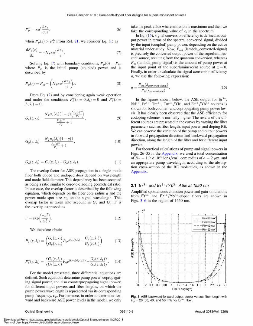
Amplified spontaneous emission power and gain simulationsfrom Er3þ and Er3þ∕Yb3þ-doped fibers are shown inFigs. 3–6 in the region of 1550 nm.
Fig. 3 ASE backward-forward output power versus fiber length withPp ¼ 20, 30, 40, and 50 mW for Er3þ fiber.
Optical Engineering 086110-3 August 2013/Vol. 52(8)
Pérez-Sánchez et al.: Rare-earth-doped fiber designs for superluminescent sources
Downloaded From: https://www.spiedigitallibrary.org/journals/Optical-Engineering on 11/27/2018Terms of Use: https://www.spiedigitallibrary.org/terms-of-use

2.2 Tm3þ ASE at 1900 nm
Note that in Figs. 3, 5, 7–10 ASE backward output power isthe ASE power level that propagates in the opposite directionof the pump power. ASE forward output power is the ASEpower level that propagates in the same direction of the pumppower. We showed the calculated conversion efficiency val-ues, which depend on absorption and emission cross-sec-tions for each active material studied. Also, in Figs. 3, 5,7–10, we showed the efficiency ηbw as the signal conversionefficiency in the opposite direction with respect to the pump.As for ηfw, it defines the signal conversion efficiency in thesame direction as the pump, i.e., forward.
2.3 Nd3þ ASE at 1310 nm
As we can observe in Figs. 11, 12, 13, and 14, the pumppower evolution along the fiber shows a declining behavior
Fig. 4 Net gain versus fiber length with Pp ¼ 20 mW. Er3þ fiber.
Fig. 5 ASE backward-forward output power versus fiber length withPp ¼ 20, 30, 40, and 50 mW for Er3þ∕Yb3þ fiber.
Fig. 6 Net gain versus fiber length with Pp ¼ 20 mW. Er3þ∕Yb3þfiber.
Fig. 7 ASE backward-forward output power versus fiber length withPp ¼ 20, 30, 40, and 50 mW. Tm3þ fiber.
Fig. 8 ASE backward-forward output power versus fiber length withPp ¼ 20, 30, 40, and 50 mW. Tm3þ∕Yb3þ fiber.
Optical Engineering 086110-4 August 2013/Vol. 52(8)
Pérez-Sánchez et al.: Rare-earth-doped fiber designs for superluminescent sources
Downloaded From: https://www.spiedigitallibrary.org/journals/Optical-Engineering on 11/27/2018Terms of Use: https://www.spiedigitallibrary.org/terms-of-use

Fig. 9 ASE backward-forward output power versus fiber length withPp ¼ 20, 30, 40, and 50 mW. Nd3þ fiber.
Fig. 10 ASE backward-forward output power versus fiber length withPp ¼ 50, 60, 70, and 80 mW. Nd3þ fiber.
Fig. 11 Pp versus fiber length with Pp ¼ 20, 30, 40, and 50 mW forEr3þ fiber.
Fig. 12 Pp versus fiber length with Pp ¼ 20, 30, 40, and 50 mW.Tm3þ fiber.
Fig. 13 Pp versus fiber length with Pp ¼ 20, 30, 40, and 50mW. Nd3þfiber.
Fig. 14 Pp versus fiber length with Pp ¼ 50, 60, 70, and 80mW. Nd3þfiber.
Optical Engineering 086110-5 August 2013/Vol. 52(8)
Pérez-Sánchez et al.: Rare-earth-doped fiber designs for superluminescent sources
Downloaded From: https://www.spiedigitallibrary.org/journals/Optical-Engineering on 11/27/2018Terms of Use: https://www.spiedigitallibrary.org/terms-of-use

as background losses and pump energy absorption take placein the pump propagation direction. Absorption cross-sectionof RE molecules use up the available energy for populationinversion and ASE after nonradiative decay from thecorresponding excited-state levels, which in turn will allowbroadband photon emission. Let us consider that under cer-tain fiber-end circumstances, feedback from Rayleigh back-scattering could be sufficient to drive the ASE source abovelasing threshold, which would limit ASE power level at theoutput.
Figures 3, 5, 7–10 represent output power behavior in for-ward and backward propagation directions along the fiberlength for the whole set of REs included in this paper. Itcan be seen that the backward power is, in general, slightlylarger than the forward power due to absorption within thefirst few sections of the fiber, which generated higher pop-ulation inversion in those first few fiber sections and whichcould create an unbalanced ASE source. Figures 15, 16, 17,
Fig. 15 Net gain versus fiber length with Pp ¼ 20 mW. Tm3þ fiber.
Fig. 16 Net gain versus fiber length with Pp ¼ 20 mW. Tm3þ∕Yb3þfiber.
Fig. 17 Net gain versus fiber length with Pp ¼ 20 mW. Ndþ fiber.
Fig. 18 Net gain versus fiber length with Pp ¼ 80 mW. Nd3þ fiber.
Fig. 19 Pp versus fiber length with Pp ¼ 500, 600, 700, and 800 mW.Pr3þ fiber.
Optical Engineering 086110-6 August 2013/Vol. 52(8)
Pérez-Sánchez et al.: Rare-earth-doped fiber designs for superluminescent sources
Downloaded From: https://www.spiedigitallibrary.org/journals/Optical-Engineering on 11/27/2018Terms of Use: https://www.spiedigitallibrary.org/terms-of-use

and 18, represent net gain versus fiber length for Tm3þ andNd3þ. Figures 19–21 show pump power, backward and for-wards ASE power and net gain, all versus fiber length, forPr 3þ sources, respectively.
Some of the applications for 1310 nm ASE sources, suchas the ones analyzed in this paper, could include optical com-ponent characterization, optical measurement systems, andoptical sensing, within the O band. Please note that inearly communication systems, the wavelength region situ-ated between 1260 and 1360 nm was called “originalband” and that this is the reason it is typically called “Oband” as this band is used in different applications suchas fiber to the home, among others. In terms of quantum effi-ciency, for a given fiber length and a given pump powerlevel, the total gain varies along the fiber depending onthe absorption and emission Ga and Ge coefficients,which describe the absorption and emission parameters,respectively.21
2.4 Tm3þ ASE S-band at 1470 nm
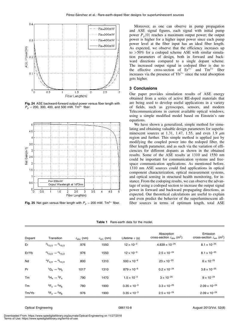
As can be observed in Figs. 22 to 25, it has been necessary toincrease the input power required for broadband generationand consequently maximum efficiency, which reached up to58% in the present study.
In Fig. 23, we showed the efficiency ηbw as the signalconversion efficiency in the opposite direction with respectto the pump. As for ηfw, it defines the signal conversion effi-ciency in the same direction as the pump, i.e., forward.
2.5 Pr 3þ ASE O-band at 1310 nm
As expected, the specific design changes due to quantumcharacteristics natural of each RE.
The lifetime values that were used in this work are listedin Table 1, along with the emission and absorption cross-sec-tion values for the different active dopant materials studied inthis paper.
Fig. 21 Net gain versus fiber length with Pp ¼ 500 mW. Pr3þ fiber.
Fig. 22 Pp versus fiber length with Pp ¼ 20, 30, 40, and 50 mW.Tm3þ fiber.
Fig. 23 ASE backward-forward output power versus fiber length withPp ¼ 20, 30, 40, and 50 mW. Tm3þ fiber.
Fig. 20 ASE backward-forward output power versus fiber length withPp ¼ 500, 600, 700, and 800 mW. Pr3þ fiber.
Optical Engineering 086110-7 August 2013/Vol. 52(8)
Pérez-Sánchez et al.: Rare-earth-doped fiber designs for superluminescent sources
Downloaded From: https://www.spiedigitallibrary.org/journals/Optical-Engineering on 11/27/2018Terms of Use: https://www.spiedigitallibrary.org/terms-of-use
Moreover, as one can observe in pump propagationand ASE signal figures, each signal with initial pumppower Ppð0Þ reaches a maximum output power; the outputpower is higher for a higher input power since each pumppower level at the fiber input has an ideal fiber length.As expected, we observe that the efficiency increases upto >50% for a codoped scheme ASE with similar simula-tion parameters of design, both in forward and back-ward directions compared to a single dopant scheme.The increased output signal in codoped fiber is due tothe effective cross-section of Er3þ and Tm3þ fiberincreases via the presence of Yb3þ since the total absorptiongets higher.
3 ConclusionsOur paper provides simulation results of ASE energyobtained from a series of active RE-doped materials thatare being used to develop useful applications in a varietyof fields, such as gyroscopes, sensors, and modernTelecommunications in current available optical windows,using a simple modified model based on Einstein’s rateequations.
We have shown a generalized, simple method for simu-lating and obtaining valuable design parameters for superlu-minescent sources at 1.31, 1.47, 1.55, and even 1.9 μmregion and further. This simple method is applied just bymodifying the coupled power into the redoped fiber, thefiber length parameter, and as such via the variation of effi-ciencies for different dopants as shown in the obtainedresults. Some of the ASE results at 1310 and 1550 nmcould be important for communication systems and free-space communication applications. As mentioned before,1310 nm ASE sources could find applications in opticalcomponent characterization, optical measurement systems,and optical sensing in structural health monitoring, for in-stance. From the codoping results, we can observe the advan-tage of using a codoped section to increase the output signalpower in forward and backward propagating directions, asexpected. Our theoretical calculations are useful to explainand even predict the behavior of the superluminescent all-fiber sources in terms of optimum length, total ASE
Table 1 Rare-earth data for the model.
Dopant Transition λabs (nm) λem (nm) Lifetime τ (s)Absorption
cross-section λabs (m2)Emission
cross-section λem (m2)
Er 4I13∕2 → 4I15∕2 976 1550 12 × 10−3 4.839 × 10⁻²⁵ 8.1 × 10⁻²⁵
Er/Yb 4I13∕2 → 4I15∕2 976 1550 12 × 10−3 2.5 × 10⁻²⁴ 8.1 × 10⁻²⁵
Nd 4F3∕2 → 4I13∕2 800 1310 500 × 10−6 23 × 10−25 6 × 10⁻²⁵
Pr 1G4 → 3H5 1017 1310 879 × 10−6 0.2 × 10⁻²⁴ 3.8 × 10⁻²⁵
Tm 3H4 → 3F4 790 1470 1.5 × 10⁻³ 3 × 10⁻²⁵ 9 × 10⁻²⁴
Tm 3F4 → 3H6 780 1900 3.35 × 10⁻³ 3.3 × 10⁻²⁵ 2.09 × 10⁻²⁴
Tm/Yb 3F4 → 3H6 976 1900 3.35 × 10⁻³ 2.5 × 10⁻²⁴ 2.09 × 10⁻²⁴
Fig. 25 Net gain versus fiber length with Pp ¼ 200 mW. Tm3þ fiber.
Fig. 24 ASE backward-forward output power versus fiber length withPp ¼ 200, 300, 400, and 500 mW. Tm3þ fiber.
Optical Engineering 086110-8 August 2013/Vol. 52(8)
Pérez-Sánchez et al.: Rare-earth-doped fiber designs for superluminescent sources
Downloaded From: https://www.spiedigitallibrary.org/journals/Optical-Engineering on 11/27/2018Terms of Use: https://www.spiedigitallibrary.org/terms-of-use
power, gain and conversion efficiency. We can foresee thepossibility to use these kinds of fibers to design DWDMsources due to the fact that these kinds of sources have abig spectral broadband.
Finally our results could be used for designing RE-dopedsuperluminescent sources since it predicts output powersand efficiencies in both the forward and backward pumppropagation directions. We could venture to recommendour paper for investigating new designs of ASE sources,using a method that modifies the fiber parameters in a sim-ple way, via an optimization route for the desiredapplication.
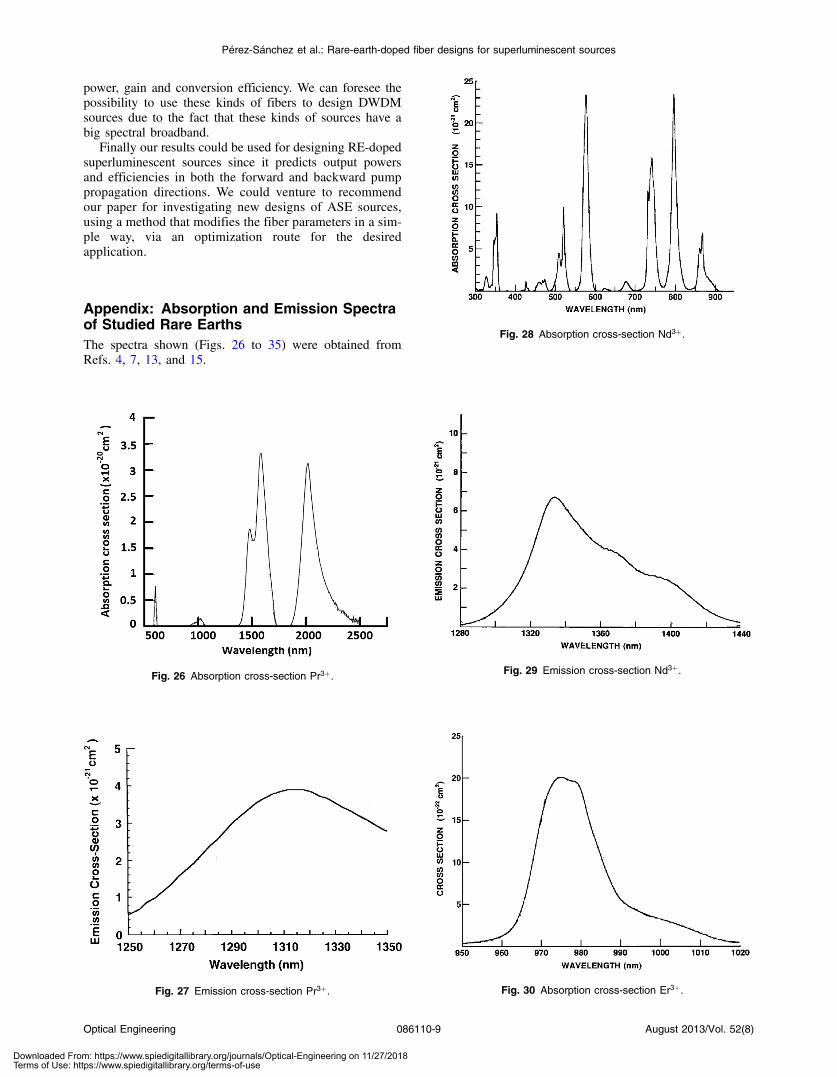
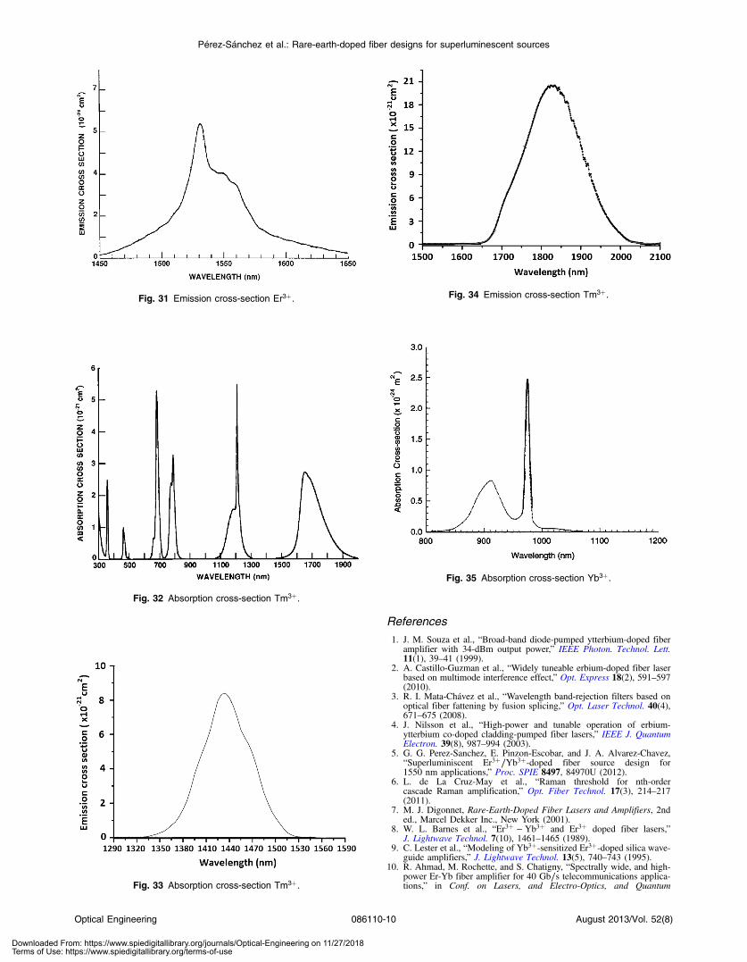
Appendix: Absorption and Emission Spectraof Studied Rare EarthsThe spectra shown (Figs. 26 to 35) were obtained fromRefs. 4, 7, 13, and 15.
Fig. 26 Absorption cross-section Pr3þ.
Fig. 27 Emission cross-section Pr3þ.
Fig. 28 Absorption cross-section Nd3þ.
Fig. 29 Emission cross-section Nd3þ.
Fig. 30 Absorption cross-section Er3þ.
Optical Engineering 086110-9 August 2013/Vol. 52(8)
Pérez-Sánchez et al.: Rare-earth-doped fiber designs for superluminescent sources
Downloaded From: https://www.spiedigitallibrary.org/journals/Optical-Engineering on 11/27/2018Terms of Use: https://www.spiedigitallibrary.org/terms-of-use
References
1. J. M. Souza et al., “Broad-band diode-pumped ytterbium-doped fiberamplifier with 34-dBm output power,” IEEE Photon. Technol. Lett.11(1), 39–41 (1999).
2. A. Castillo-Guzman et al., “Widely tuneable erbium-doped fiber laserbased on multimode interference effect,” Opt. Express 18(2), 591–597(2010).
3. R. I. Mata-Chávez et al., “Wavelength band-rejection filters based onoptical fiber fattening by fusion splicing,” Opt. Laser Technol. 40(4),671–675 (2008).
4. J. Nilsson et al., “High-power and tunable operation of erbium-ytterbium co-doped cladding-pumped fiber lasers,” IEEE J. QuantumElectron. 39(8), 987–994 (2003).
5. G. G. Perez-Sanchez, E. Pinzon-Escobar, and J. A. Alvarez-Chavez,“Superluminiscent Er3þ∕Yb3þ-doped fiber source design for1550 nm applications,” Proc. SPIE 8497, 84970U (2012).
6. L. de La Cruz-May et al., “Raman threshold for nth-ordercascade Raman amplification,” Opt. Fiber Technol. 17(3), 214–217(2011).
7. M. J. Digonnet, Rare-Earth-Doped Fiber Lasers and Amplifiers, 2nded., Marcel Dekker Inc., New York (2001).
8. W. L. Barnes et al., “Er3þ − Yb3þ and Er3þ doped fiber lasers,”J. Lightwave Technol. 7(10), 1461–1465 (1989).
9. C. Lester et al., “Modeling of Yb3þ-sensitized Er3þ-doped silica wave-guide amplifiers,” J. Lightwave Technol. 13(5), 740–743 (1995).
10. R. Ahmad, M. Rochette, and S. Chatigny, “Spectrally wide, and high-power Er-Yb fiber amplifier for 40 Gb∕s telecommunications applica-tions,” in Conf. on Lasers, and Electro-Optics, and Quantum
Fig. 31 Emission cross-section Er3þ.
Fig. 32 Absorption cross-section Tm3þ.
Fig. 33 Absorption cross-section Tm3þ.
Fig. 34 Emission cross-section Tm3þ.
Fig. 35 Absorption cross-section Yb3þ.
Optical Engineering 086110-10 August 2013/Vol. 52(8)
Pérez-Sánchez et al.: Rare-earth-doped fiber designs for superluminescent sources
Downloaded From: https://www.spiedigitallibrary.org/journals/Optical-Engineering on 11/27/2018Terms of Use: https://www.spiedigitallibrary.org/terms-of-use

Electronics, and Laser Science, pp. 1–2, Optical Society of America,Washington, DC (2010).
11. J. Liu and P. Wang, “High-power broadband thulium-doped all-fibersuperfluorescent source at 2 um,” Photon. Technol. Lett. 25(3),242–245 (2013).
12. S. W. Harun et al., “Ytterbium-sensitized thulium-doped fiber laser witha single-mode output operating at 1 900-nm region,” Chin. Opt. Lett.10(10), 101401 (2012).
13. R. C. Schimmel, Towards More Efficient Praseodymium Doped FiberAmplifiers for the O-Band, Universiteit Eindhoven, The Netherlands(2006).
14. Y. Nishida et al., “Development of an efficient praseodymium-dopedfiber amplifier,” IEEE J. Quantum Electron. 34(8), 1332–1339 (1998).
15. E. Lebrasseura et al., “Optical amplification and laser spectroscopy ofneodymium-doped fluoride glass channel waveguides,” J. AlloysCompd. 275–277, 716–720 (1998).
16. R. F. Kalman, M. J. F. Digonnet, and P. F. Wysocki, “Modeling of three-level laser superfluorescent fiber sources,” Proc. SPIE 1373, 209–222(1990).
17. P. F. Moulton et al., “Tm-doped fiber lasers: fundamentals and powerscaling,” IEEE J. Sel. Topics Quantum Electron. 15(1), 85–92 (2009).
18. O. Mahran et al., “Wavelength division multiplexing of yttria-alumina-silica doped with thulium optical fiber amplifiers,” Int. J. Res. Rev. Appl.Sci. 10(2), 314–321 (2012).
19. E. Desurvire and J. R. Simpson, “Amplification of spontaneous emis-sion in erbium-doped single mode fiber,” J. Lightwave Technol. 7(5),835–845 (1989).
20. G. E. Sandoval-Romero, V. Argueta-Díaz, and O. Pottiez, “Theoreticalresults of the analytical and numerical solutions of superluminescentfiber sources,” Phys. Status Solidi C 6(S1), S227–S230 (2009).
21. E. F. Pinzón-Escobar et al., “Experimental results of the superlumines-cent fiber laser sources for fiber optic sensors,” Proc. SPIE 7839,78391R (2010).
Grethell G. Pérez-Sánchez obtained aBEng degree in electronics at MetropolitanAutonomous University, Mexico City, in2005, an MSc in telecommunications atEscuela Superior de Ingenieria Mecanica yElectrica—Instituto Politecnico Nacional in2011, and is now pursuing a PhD in all-fiber superluminescent sources at Centrode Invetigacion e Innovacion Tecnologica—Instituto Politecnico Nacional. Her researchinterests range from active and passive
fiber devices for telecom and other applications to semiconductorand fiber amplifiers and nonlinear dynamics. She is a member andcofounder of IPN SPIE student chapter and has presented herwork in a few international conferences and meetings.
Indayara Bertoldi-Martins received a bach-elor’s degree in electrical engineering withemphasis in telecommunications from thePontifical Catholic University of Campinasin 2004 and an MS degree and PhD fromthe School of Electrical and Computer Engi-neering of State University of Campinas in2007 and 2011. Currently she is postdoctoralin Telecom ParisTech. Her interests are inthe field of optical communications such asresearch related to transport layer and
physical layer for the development of future optical networktechnologies.
Philippe Gallion received his PhD from theUniversity of Reims in 1975 and the Doctor-ates Science from the University of Montpel-lier in 1986. His present research topics focuson advanced digital communications sys-tems and networks, quantum communicationand quantum cryptography, nonlinearity andnoise in Raman distributed optical amplifiers.He is a full professor at Télécom Paris Tech.He is an author of several text books, morethan 130 international technical publications,
and more than 130 communications and lectures at conferences. Heis a member of the Optical Society of America and a senior member ofthe Institute of Electrical and Electronics Engineers. He is the chair-man of the IEEE Photonics Society (formerly Laser and Electro OpticsSociety) French Chapter. He serves on the editorial board and scien-tific committee of several technical publications and as a member ofprogram or steering committee of international scientific meeting.
Jose A. Alvarez-Chávez received a BEngdegree in mechanics at Universidad NacionalAutonoma de Mexico in 1992, obtained anMSc in telecommunications from Centro deInvestigacion Cientifica y de EducacionSuperior de Ensenada in 1994, and a PhDin fiber lasers and amplifiers from the Opto-electronics Research Centre, SouthamptonUniversity in 2003. He worked for TelMexand Iusacell in Mexico and Xtera Communi-cations Inc. in the United States in 2002, and
Southampton Photonics Ltd. in the United Kingdom in 2005. Hisresearch activities include all-fiber active and passive devices,high-power fiber lasers and amplifiers and fiber sensors. He hasbeen a senior research fellow at Centro de Invetigacion e InnovacionTecnologica—Instituto Politecnico Nacional since 2007.
Optical Engineering 086110-11 August 2013/Vol. 52(8)
Pérez-Sánchez et al.: Rare-earth-doped fiber designs for superluminescent sources
Downloaded From: https://www.spiedigitallibrary.org/journals/Optical-Engineering on 11/27/2018Terms of Use: https://www.spiedigitallibrary.org/terms-of-use