Embed Size (px)
DESCRIPTION
User Manual for RASS-S, an tool for evaluation of Air traffic sensor data.
Citation preview
RASS-S v6.2Covers SASS-S ; PTE P1-P2-P5 ; RASS-MRASS-S v6.2Covers SASS-S ; PTE P1-P2-P5 ; RASS-M
Conform RASS-S v6.2.x ProductConforms RASS-M v6.2.0 Product Conform PTE P1-P2-P5 v6.2.0Product
Released - April 2005
Radar Analysis Support System for SiteMeasurements
User Manual
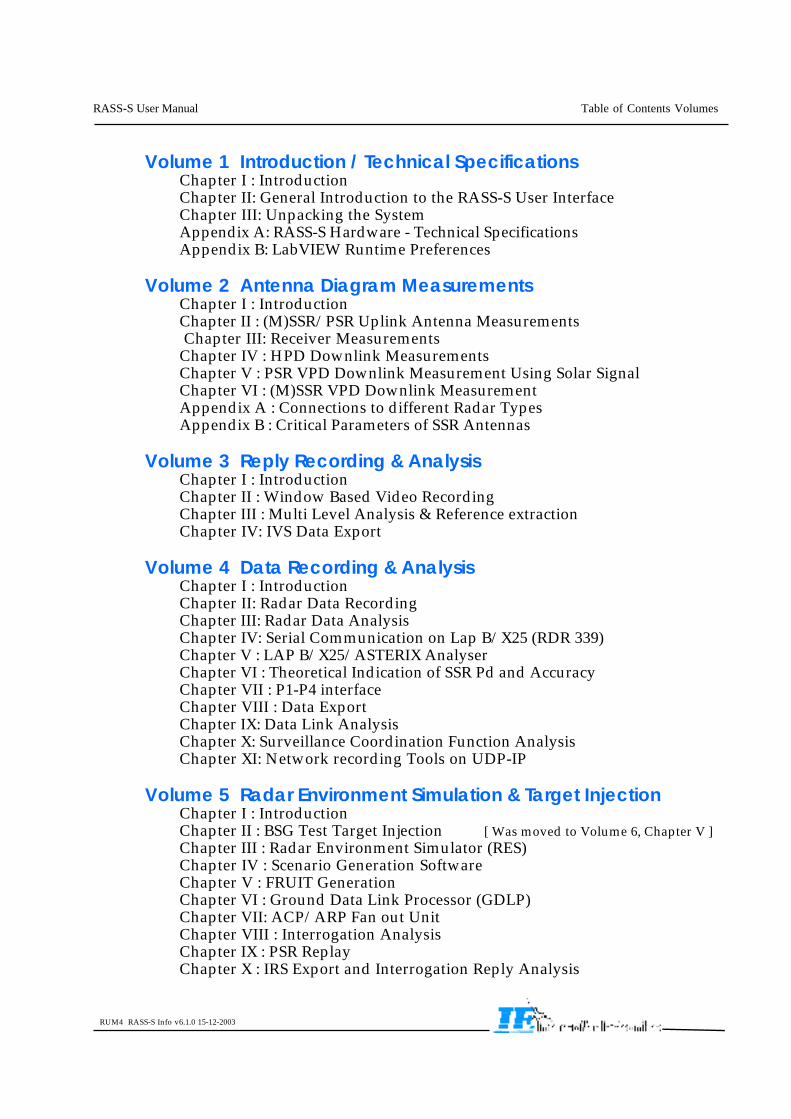
Volume 1 Introduction / Technical SpecificationsChapter I : IntroductionChapter II: General Introduction to the RASS-S User InterfaceChapter III: Unpacking the SystemAppendix A: RASS-S Hardware - Technical SpecificationsAppendix B: LabVIEW Runtime Preferences
Volume 2 Antenna Diagram MeasurementsChapter I : IntroductionChapter II : (M)SSR/PSR Uplink Antenna Measurements Chapter III: Receiver MeasurementsChapter IV : HPD Downlink MeasurementsChapter V : PSR VPD Downlink Measurement Using Solar SignalChapter VI : (M)SSR VPD Downlink MeasurementAppendix A : Connections to different Radar TypesAppendix B : Critical Parameters of SSR Antennas
Volume 3 Reply Recording & AnalysisChapter I : IntroductionChapter II : Window Based Video RecordingChapter III : Multi Level Analysis & Reference extractionChapter IV: IVS Data Export
Volume 4 Data Recording & AnalysisChapter I : IntroductionChapter II: Radar Data RecordingChapter III: Radar Data AnalysisChapter IV: Serial Communication on Lap B/X25 (RDR 339)Chapter V : LAP B/X25/ASTERIX AnalyserChapter VI : Theoretical Indication of SSR Pd and AccuracyChapter VII : P1-P4 interfaceChapter VIII : Data ExportChapter IX: Data Link AnalysisChapter X: Surveillance Coordination Function AnalysisChapter XI: Network recording Tools on UDP-IP
Volume 5 Radar Environment Simulation & Target InjectionChapter I : IntroductionChapter II : BSG Test Target Injection [ Was moved to Volume 6, Chapter V ]Chapter III : Radar Environment Simulator (RES)Chapter IV : Scenario Generation SoftwareChapter V : FRUIT GenerationChapter VI : Ground Data Link Processor (GDLP)Chapter VII: ACP/ARP Fan out UnitChapter VIII : Interrogation AnalysisChapter IX : PSR ReplayChapter X : IRS Export and Interrogation Reply Analysis
RASS-S User Manual Table of Contents Volumes
RUM4 RASS-S Info v6.1.0 15-12-2003
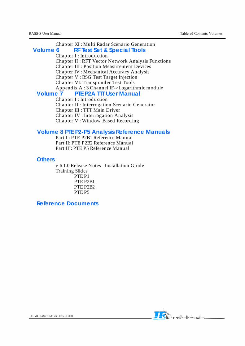
Chapter XI : Multi Radar Scenario GenerationVolume 6 RF Test Set & Special Tools
Chapter I : IntroductionChapter II : RFT Vector Network Analysis FunctionsChapter III : Position Measurement DevicesChapter IV : Mechanical Accuracy AnalysisChapter V : BSG Test Target InjectionChapter VI: Transponder Test ToolsAppendix A : 3 Channel IF->Logarithmic module
Volume 7 PTE P2A TTT User ManualChapter I : IntroductionChapter II : Interrogation Scenario GeneratorChapter III : TTT Main DriverChapter IV : Interrogation AnalysisChapter V : Window Based Recording
Volume 8 PTE P2-P5 Analysis Reference ManualsPart I : PTE P2B1 Reference ManualPart II: PTE P2B2 Reference ManualPart III: PTE P5 Reference Manual
Othersv 6.1.0 Release Notes Installation GuideTraining Slides
PTE P1PTE P2B1PTE P2B2PTE P5
Reference Documents
RASS-S User Manual Table of Contents Volumes
RUM4 RASS-S Info v6.1.0 15-12-2003
PTE Reference Documents - I / 1 –
06-06-2001
1. PTE Reference Documents
1.1. Asterix Part 1
Eurocontrol Standard Document for Radar Data Exchange Part 1All Purpose Structured EuroControl Radar Information Exchange (ASTERIX)SUR.ET1.ST05.2000-STD-01-01 Ed 1.0 November 1997 Released Issue.
Eurocontrol Standard Document for Radar Data Exchange Part 1All Purpose Structured EuroControl Radar Information Exchange (ASTERIX)SUR.ET1.ST05.2000-STD-01-01 Ed 1.26 November 2000 Proposed Standard.
1.2. Asterix Part 2a Cat 001
Cat 1 Eurocontrol Standard Document for Radar Data Exchange Part 2aTransmission of Monoradar Data Target Reports Ref.SUR.ET1.ST05.2000-STD-02a-01 Ed 1.0 November 1997 Released Issue.
1.3. Asterix Part 2b Cat 002
Cat 2 Eurocontrol Standard Document for Radar Data Exchange Part 2bTransmission of Monoradar Service Messages Ref. SUR.ET1.ST05.2000-STD-02b-01Ed 1.0 November 1997 Released Issue.
1.4. Asterix Part 2b Cat 002
Cat 34 POEMS Document for Radar Data Exchange Part 2b Transmissionof Monoradar Service Messages Ref. SUR.ET2.ST03.3116-SPC-02b-01 Ed 1.3 16March 1999 Proposed Issue.
1.5. Asterix Part 3 Cat 008
Cat 08 Eurocontrol Standard Document for Radar Data Exchange Part 3 Transmissionof Monoradar Derived Weather Information Ref. SUR.ET1.ST05.2000-STD-03-01 Ed1.0 November 1997 Released Issue.
1.6. Asterix Part 4 Cat 048
Cat 48 POEMS Document for Radar Data Exchange Part 4 Transmission ofMonoradar Target Reports Ref. SUR.ET2.ST03.3115-SPC-04-01 Ed 1.3 12 March1999 Proposed Issue.
1.7. Asterix Part 5 Cat 017
Cat 17 POEMS Document for ASTERIX Category 017 Transmission of ModeS Surveillance Co-ordination Function Messages Ref.SUR.ET2.ST03.3111-SPC-02-00 Ed 0.5 February 1999 Proposed Issue
1.8. Asterix Part 6 Cat 018
Cat 18 POEMS Document for ASTERIX Category 018 (Part 6) Transmissionof Mode S Datalink Function Messages Ref. SUR.ET2.ST03.3112-SPC-02-00 Ed 1.5March 1999 Proposed Issue.
PTE Reference Documents - I / 2 –
09-10-2001
1.9. Asterix Part 7 Cat 010
Cat 08 Eurocontrol Standard Document for Radar Data Exchange Part 7 Transmissionof Monoradar Surface movement Data Ref. SUR.ET1.ST05.2000-STD-07-01 November1997 Working Draft.
1.10. Asterix Part 9 Cat 062
Cat 08 Eurocontrol Standard Document for Radar Data Exchange Part 7 Transmissionof System Track Data Ref. SUR.ET1.ST05.2000-STD-09-01November 2000 WorkingDraft.
1.11. Data link Function ICD
DLF ICD EATCHIP GDLP/Local User ICD for POEMSSUR-ET2-ST03.3112-SPC-02-00 Ed 1.7 17 March 1999 Proposed Issue
1.12. Surveillance Coordination Network ICD
SCN ICD EATCHIP. Intersite Co-ordination ICD for POEMS EurocontrolSUR-ET2-ST03.3110-SPC-02-00 Edition 1.9 dated 3 June 98.
1.13. Map ICD
MAP ICD Coverage Map Interface Control Document for POEMS stations,Ref. SUR-ET2-ST03.3113-SPC-01.00, version 1.11 15 March 1999.
1.14. PTE P1-P2-P5 ICD
PTE Interface Control Document;. Version 3.0 October 2001
1
New Developments April 2005 : RASS-S v6.2 Release
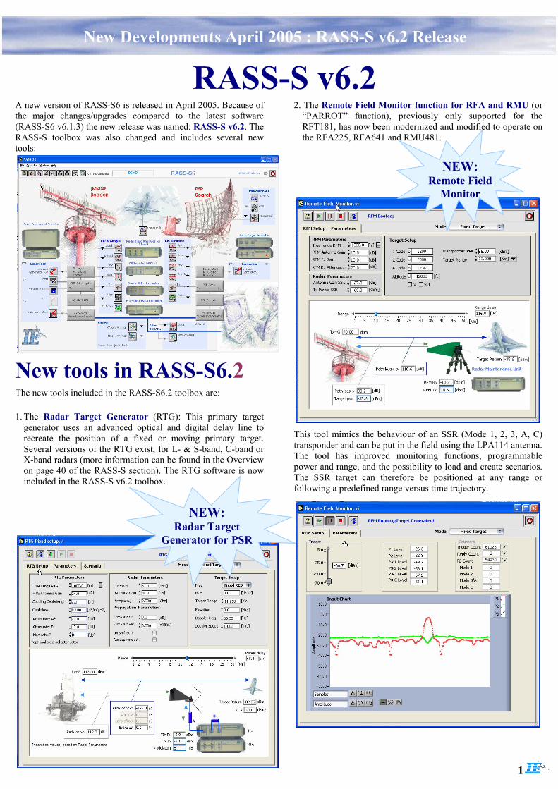
A new version of RASS-S6 is released in April 2005. Because of the major changes/upgrades compared to the latest software (RASS-S6 v6.1.3) the new release was named: RASS-S v6.2. The RASS-S toolbox was also changed and includes several new tools:
RASS-S v6.2
The new tools included in the RASS-S6.2 toolbox are:
1. The Radar Target Generator (RTG): This primary target generator uses an advanced optical and digital delay line to recreate the position of a fixed or moving primary target. Several versions of the RTG exist, for L- & S-band, C-band or X-band radars (more information can be found in the Overview on page 40 of the RASS-S section). The RTG software is now included in the RASS-S v6.2 toolbox.
2. The Remote Field Monitor function for RFA and RMU (or “PARROT” function), previously only supported for the RFT181, has now been modernized and modified to operate on the RFA225, RFA641 and RMU481.
This tool mimics the behaviour of an SSR (Mode 1, 2, 3, A, C) transponder and can be put in the field using the LPA114 antenna. The tool has improved monitoring functions, programmable power and range, and the possibility to load and create scenarios. The SSR target can therefore be positioned at any range or following a predefined range versus time trajectory.
New tools in RASS-S6.2
NEW: Radar Target
Generator for PSR
NEW: Remote Field
Monitor
2
New Developments April 2005 : RASS-S v6.2 Release
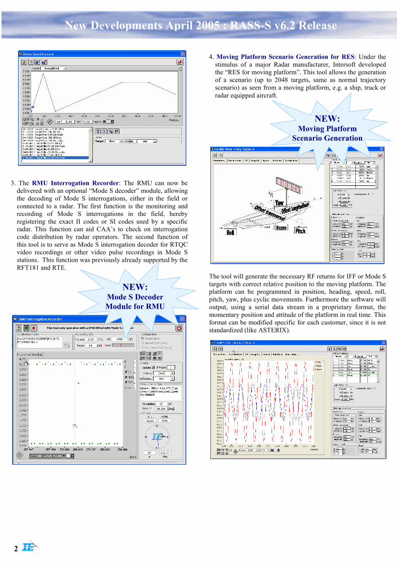
3. The RMU Interrogation Recorder: The RMU can now be delivered with an optional “Mode S decoder” module, allowing the decoding of Mode S interrogations, either in the field or connected to a radar. The first function is the monitoring and recording of Mode S interrogations in the field, hereby registering the exact II codes or SI codes used by a specific radar. This function can aid CAA’s to check on interrogation code distribution by radar operators. The second function of this tool is to serve as Mode S interrogation decoder for RTQC video recordings or other video pulse recordings in Mode S stations. This function was previously already supported by the RFT181 and RTE.
4. Moving Platform Scenario Generation for RES: Under the stimulus of a major Radar manufacturer, Intersoft developed the “RES for moving platform”. This tool allows the generation of a scenario (up to 2048 targets, same as normal trajectory scenario) as seen from a moving platform, e.g. a ship, truck or radar equipped aircraft.
The tool will generate the necessary RF returns for IFF or Mode S targets with correct relative position to the moving platform. The platform can be programmed in position, heading, speed, roll, pitch, yaw, plus cyclic movements. Furthermore the software will output, using a serial data stream in a proprietary format, the momentary position and attitude of the platform in real time. This format can be modified specific for each customer, since it is not standardized (like ASTERIX).
NEW: Mode S Decoder Module for RMU
NEW: Moving Platform
Scenario Generation
3
New Developments April 2005 : RASS-S v6.2 Release
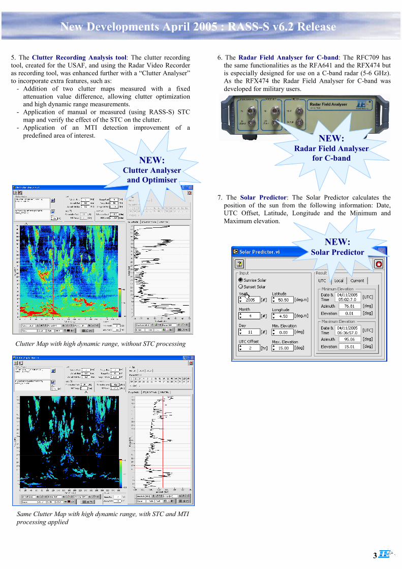
5. The Clutter Recording Analysis tool: The clutter recording tool, created for the USAF, and using the Radar Video Recorder as recording tool, was enhanced further with a “Clutter Analyser” to incorporate extra features, such as:
- Addition of two clutter maps measured with a fixed attenuation value difference, allowing clutter optimization and high dynamic range measurements.
- Application of manual or measured (using RASS-S) STC map and verify the effect of the STC on the clutter.
- Application of an MTI detection improvement of a predefined area of interest.
Clutter Map with high dynamic range, without STC processing
Same Clutter Map with high dynamic range, with STC and MTI processing applied
NEW: Clutter Analyser and Optimiser
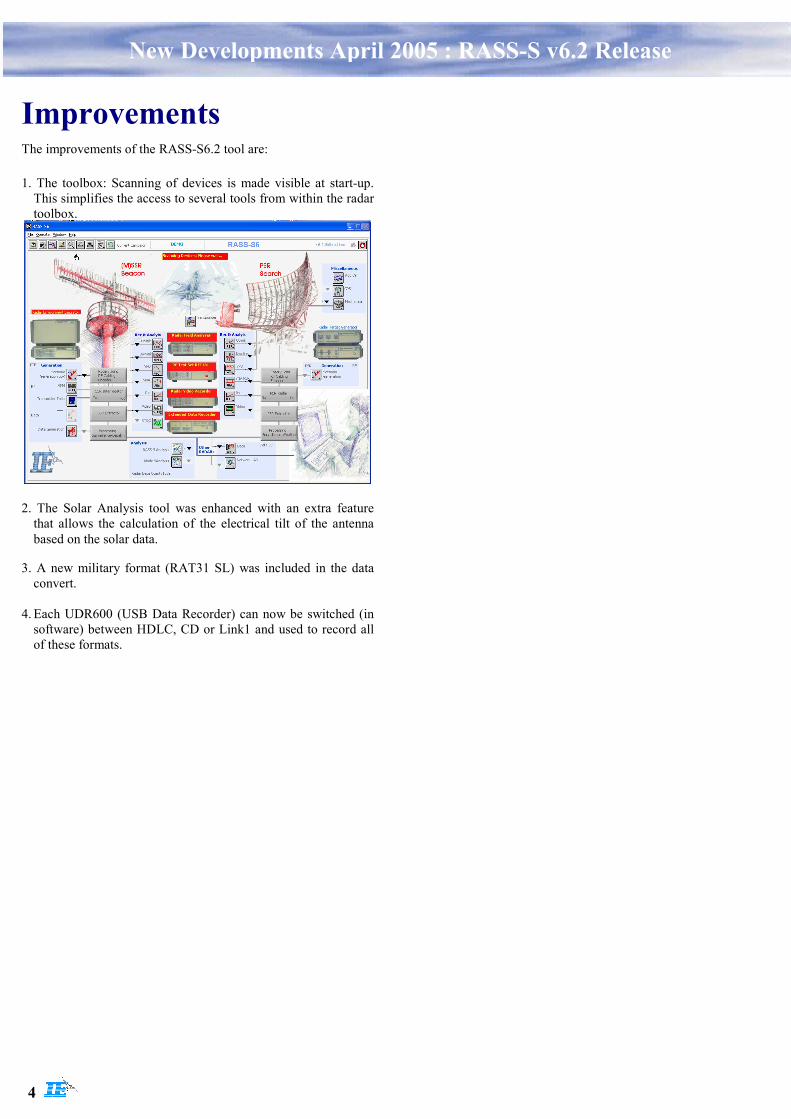
6. The Radar Field Analyser for C-band: The RFC709 has the same functionalities as the RFA641 and the RFX474 but is especially designed for use on a C-band radar (5-6 GHz). As the RFX474 the Radar Field Analyser for C-band was developed for military users.
NEW: Radar Field Analyser
for C-band
7. The Solar Predictor: The Solar Predictor calculates the position of the sun from the following information: Date, UTC Offset, Latitude, Longitude and the Minimum and Maximum elevation.
NEW: Solar Predictor
4
New Developments April 2005 : RASS-S v6.2 Release
Improvements The improvements of the RASS-S6.2 tool are:
1. The toolbox: Scanning of devices is made visible at start-up. This simplifies the access to several tools from within the radar toolbox.
2. The Solar Analysis tool was enhanced with an extra feature that allows the calculation of the electrical tilt of the antenna based on the solar data.
3. A new military format (RAT31 SL) was included in the data convert.
4. Each UDR600 (USB Data Recorder) can now be switched (in
software) between HDLC, CD or Link1 and used to record all of these formats.
RASS-S/SASS-Se/PTE P1-P2-P5
Release v 6.1.2 Release Notes
Edition : 6.1.2Edition Date : 15-12-2003Status : Proposed Issue
A Product of

Edition1.5 24-05-2004
2
DOCUMENT IDENTIFICATION SHEET
DOCUMENT DESCRIPTION
Document TitleRASS-S/SASS-Se/PTE v6.1.2 Release Notes
Document Reference Number EDITION : 1.5
008Release Notes v613.doc EDITION DATE : 24-05-2004
Abstract
Keywords
CONTACT PERSON : A.Vander Cruyssen TEL : +32 14 231811 :
DOCUMENT STATUS AND TYPE
STATUS CATEGORYWorking Draft Executive Task o
Draft o Specialist TaskProposed Issue o Lower Layer Task o
Released Issue ¤
ELECTRONIC BACKUP
INTERNAL REFERENCENAME :
008Release Notes v613.doc
HOST SYSTEM MEDIA SOFTWARE(S)Mac OS 9.2.2G4 Type : Hard disk Word 98
Media Identification :
RASS-S6 Release 6.1.2
Edition1.5 24-05-2004
3
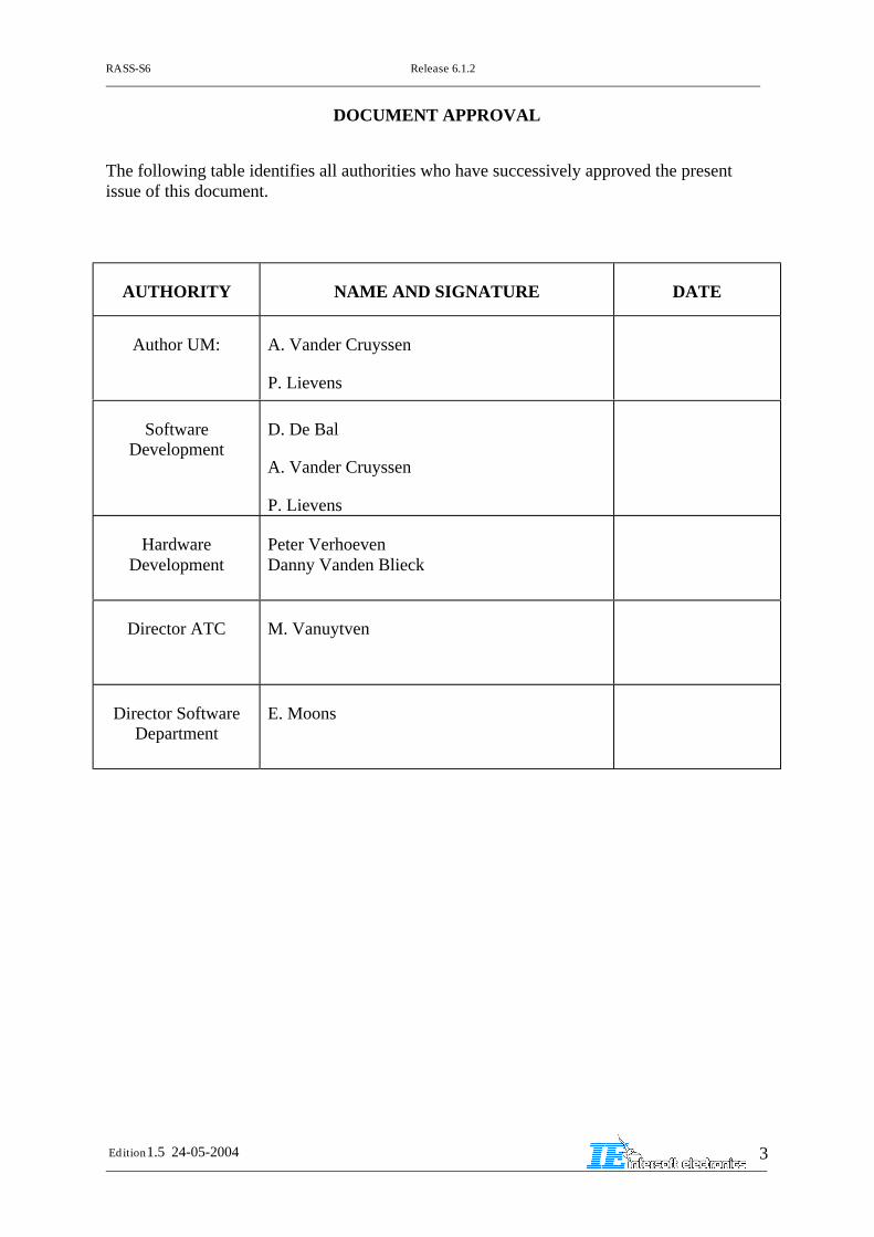
DOCUMENT APPROVAL
The following table identifies all authorities who have successively approved the presentissue of this document.
AUTHORITY NAME AND SIGNATURE DATE
Author UM: A. Vander Cruyssen
P. Lievens
SoftwareDevelopment
D. De Bal
A. Vander Cruyssen
P. Lievens
HardwareDevelopment
Peter VerhoevenDanny Vanden Blieck
Director ATC M. Vanuytven
Director SoftwareDepartment
E. Moons
RASS-S6 Release 6.1.2
Edition1.5 24-05-2004
4
1. Installation Guideline
Before starting installation make sure to have a backup of all your data (especially thecampaign folders containing your measurement data and results).
1.1. Installation Guidelines for existing installationsThe installer will first check the PC on the presence of an already earlier installedversion. If an installed version is detected you will be prompted. The installerprogram will then only replace the existing RASS-S6 software. The existingCAMPAIGN-S6 folder will be left untouched, except for the Demo Campaign folder.
The installer program will guide you through the process. When prompted to selectthe harddisk for installation, select the appropriate drive.
Remarks:
- The RASS-S6.1.x software assumes that a SCSI interface is correctly installed.
- Only Adaptec 2940A/U and Adaptec 19160 SCSI card for desktop systems andthe Adaptec APA 1480 SCSI interfaces are supported.
-
1.2. Installation Guidelines for new installationsThis assumes no RASS-S6.1.x software has been installed on the PC before.
The installation process for installing RASS-6.1.x is a fully automated process. Insertthe RASS-6 installation CD in your PC CD drive.
The Installer CD is an autostart type. The installer program automatically starts andprompts you to ask for the necessary information as soon as the CD is mounted.
The installer program will guide you through the installation process. Whenprompted to select the harddisk for installation, select the appropriate drive.
RASS-S6 Release 6.1.2
Edition1.5 24-05-2004
5
2. What’s special in this release?
2.1.1. Version 6.1.3
RASS-S 6.1.3 Includes a number of new developments for the RES specifically forEADS. .
-A full Mode 4 support ( Creation of Mode 4 replies) for the RES. The Mode 4 repliesare based on values passed by the event scenario generator.
-The generation of Jammer signals as specified in STANAG 4193 Part 2. By the RES
-The Generation of a scenario based on a Moving platform ( e.g. a ship) by the RES.
2.1.2. Version 6.1.2
RASS-S v v6.1.2. Rel;ease fixes a number of bugs that were found in version 6..1.0 and6.1.1 , and was syncronised with SASS_S / PTE release 4..4.7 , which was the lastversion 4 release. This implies that this release can also be used for PTE P1, P2 or P5analysis. Although the use of PTE P5 was not validated in this version, we believethat the results are correct and accurate.
-Some known smaller errors in PTE P5 have been resolved in this release.Furthermore, some tools have been enhanced, such as the multi radar scenariogenerator , which now allows its user to add maps ( SMGET) and use these maps todetermine the detection of plots.
-This version adds the “custom replay” function, allowing the generation of arbitraryasterix messages to be replayed on LAN or Serial lines.
-Version 6.1.2 now adds to this the “syncronised start” , allowing a LAN replay to bestarted simultaneously with the RES replay.
-Version 6.1.2 now adds support for the new Intersoft RF Test Set RFT 646, and the Xband Vector Network analysis, specifically developed for NAMSA. ( Requires RFT646 and RFX 471.
2.1.3. Version 6.1.1
Release 6.1.1 basically was a bug fixing release of the first 6.1.0 version. No newdevelopments were included in this release.
2.1.4. Version 6.1.0
The RASS-S6 release 6.1.0. was a mayor release for the RASS-S community. Thisrelease contains a very important improvement on the RASS-S toolbox, plus itintegrates a number of dedicated tools that were built specifically for customers intoone software release.
Most important bug fixes , changes and features are:
For the toolbox:-The toolbox has been completely redesigned and now features a split between tools for SSR ( Beacon) and PSR ( Search) Radars.-The toolbox has fast access menus to all the recorded data of a campaign.-The toolbox provides a simple method to automatically detect the RASS
RASS-S6 Release 6.1.2
Edition1.5 24-05-2004
6
hardware that are connected ( RFA, RMU, RFX, etc.. ) and only shows the tools that apply.
For the RES:The Multi-scenario generator now allows the user to import Map-data ( created by the SM-GET tool).-The event scenario generator allows the creation of custom defined asterix messages for data replay
For the EDR:/ UDR-The UDR now also supports Aircat 500 protocols.-One UDR can be used for different protocols by simply re-booting. ( One protocol per UDR )
-For the Antenna Diagram measurement tools:- The Toolbox now supports all Antenna Diagram Measurement tools for four different RASS-S devices: PDP, RFA, RMU and RFX, without the need for Add-On tools.
For the RVR:- The toolbox now supports the new RTQC real time video recording and anaysis tools.- The toolbox features a split in PSR and SSR tools. The PSR side has a new“clutter recording” and “clutter analyser” function.
RASS-S6 Release 6.1.2
Edition1.5 24-05-2004
7
3. Release 6.1.2
3.1. RES related TRs- This release includes the implementation of a generator of user definable ASTERIXfields in the current replay function of the PTE P1 EDR function. This function,implemented in the P1 event scenario genereator will allow a user to define a randommessage in a hex-input field together with a scan number and azimuth of generation.The defined message is inserted in the replay datastream, normally generated by theEDR. The "normal" replay datastream contains asterix cat 1/2 or 34/48 messages. Thismodification allows the inclusion of ASTERIX cat 8 , 253 or other TBD formats. The tooldoes not validate the correctness of the Asterix format, but merely transmits the data onthe pre-programmed position in time.The tool provides for a "duplicate" function, allowing multiple identical messages to besend at different positions. This duplication can be at fixed intervals, or random.Multiple messages can be selected in the duplication process and can be re-organised ina random sequence .The same function is also operational using the LAN TCP-IP or UDP replay interface.
Requested by Raytheon
This feature has been added in release 6.1.1.
- The P1 - Trajectory Scenario Generator produced a problem when the output files areconverted towards P4. The Target Report Descriptor (I048/020 -Type) of the P4reference scenario data files was set to SSR for Mode S plots. The S4SC did also notreflect the diffence between SSR and Mode S targets in its status fields, except for theMode S address being 0 for SSR targets.
PTE TR 480 Issued by Eurocontrol CEVAP (S.A.) ;
released in 6.1.1
3.2. EDR and LAN data recording related TRs- The LAN replay function is now available with a syncronised start function, allowingthe simultaneous start of the LAN replay and the RES RF scenario injection. This impliesthat you eighter use an EDR serial recorder or a RES main tool allong with the LANreplay tool. The EDR serial recorder or the RES main have a ACP-ARP syncronisationfunction. If you start the RES main, that tool passes the "start" command to the LANreplay tool directly via a LabVIEW "Global" variabel" . If you run RES main on a separatecomputer, the computer running LAN replay must a be connected to an EDR. The EDRmust in turn be connected to the ACP -ARP output of the RES or Radar. The EDR mustbe controlled by the Serial Recorder.
Requested by Thales
This feature has been added in release 6.1.2.
___________________________________________________________________________
- The EDR Convert tool now allows the creation of SASS-C FINAL format and IOSS-Mayer format starting from serial EDR data or LAN recorded data. ( TCP-Ip or UDP-IP).A selection can be made between the two formats, and the user can select betweenrelative timestamping ( to = start of file) and absolute timestamping ( t0 = midnight ofthe same day).
PTE CP 70 requested by Eurocontrol SACSO;
released in v 6.1.2
RASS-S6 Release 6.1.2
Edition1.5 24-05-2004
8
- A new tool was added to the toolbox, allowing the chopping of EDR recordings intosmaller sections. The tool allows the user to select a time of recording of the start andend of the resulting section. The tool will then regenerate a new EDR recording folderwith .edr and .arp files.
Requested by EC
This feature has been added in release 6.1.2.
- Some problems were found in the convert tools for EADS Pex-ST data format.- The EADS PEX-ST LAN convert tools did not produce correct values:-The Elevation value ±90 deg should be included.-The correct A code flag should not be shown for PSR only targets-The ATE flags have been put in the MB 4, MB 5, MB 6 and MB 7 fields of the S4 recordsto allow filtering and viewing in the inventory.-Mode 1 code was wrong in cat 48 convert ( item 48/055); this has been corrected
Noted by EADS
This problem has been fixed in release 6.1.2.
___________________________________________________________________________
3.3. P5 Analysis related TRs- A request was made to include in the Pd and Acc tool the parameter "acquisition timeincluding All Call". This is not necessary, since this can also be done by using the option"Include All Call Targets in Pd" . This will result in the calculation of the correctacquisition time.
___________________________________________________________________________
- The P5 Data Linker had a problem with linking targets that were not always seen by allradars. It could happen that the linker created high DRN ( Duplicate Reference Numbers) ( > 128 ) , which in turn could not be seen by the SCF Status display.
Noted by EC
This problem has been fixed in release 6.1.2.
___________________________________________________________________________
- The PTE P5: filter "contains" did not work for "SCF:TAP=xxxx" of "SCF:TSP=xxx" ( e.g.xxx = succesful, running, etc.. ) . This was fixed in this release. Contains now has thesame function as "Is equal" for the TAP and TSP filters.
Noted by EC
This problem has been fixed in release 6.1.2.
___________________________________________________________________________
- -In order to limit the long "TAP is running", the "TAP/TSP is no longer running butcompleted without the status sucessful when a NNCOP/NNCOP reply transactionoccurs.
Noted by EC
Requested by EC, released in 6.1.2.
- A extra display was added to the P5 Data display. This shows a list of Mode Saddresses with the number of detections per Node. This allows the simple selection of atarget ( using a quick-filter method) or a glance of the number of detections per site pertarget.
RASS-S6 Release 6.1.2
Edition1.5 24-05-2004
9
Requested by EC ;
Released in 6.1.2
___________________________________________________________________________
- Some data recorded during CEVAP sessions could not be imported in P4. A lot of effortwas put into looking for possible errors in the P1-P4 convertor, but no error was found.As a result of this effort, the P1-P4 convertor was ammended with a text file output,allowing the export of the individual P4 records as a text file. This allows the user toverify the input data of P4 before ingesting. We think the specific data could not be inputin P4 due to a problem in the import module of P4, although neigther Intersoft orEurocontrol could prove this.
TR 474 closed in release.6.1.2
___________________________________________________________________________
- The 'Mode S Replies to PlotIRD.vi' contained the constant 12.34666 for range calculationinstead of the defined constant. This gives a small gain error for Mode S replies, also itdoes not take into account the 'Speed of light' parameter.Also the 'Sync replies to RE PlotIRD.vi (for Mode AC targets), does not use the constantand does not take into account the 'Speed of light' parameter.This was fixed in version 6.1.1
___________________________________________________________________________
3.4. RASS-S related TRs- The DSP codes for RFTS type /04 and /05 were added in version 4.4.x of software.These types were only supported by version 6 previously.
Found by IE
Released in v 6.1.2.
- SSR antenna simulation tool ( from VNA results) : The phase graph was wrong (showed amplitude in stead of phase).
This has been fixed in version 6.1.1
RASS-S6 Release 6.1.2
Edition1.5 24-05-2004
10
4. Release 6.0.x Release Notes
4.1. PTE CPs- CP61: A new tool was added to the PTE -SASS-S toolbox: The TransponderInterrogator.
This tool allows the user to interrogate a transponder with a pre-defined sequence ofinterrogations and visualise the transponder replies on video level, using the RadarField Analyser. The tool can interrogate the transponder in standard SSR mode (1,2,A,C) or Mode S ( UF 4,5,11,20,21,24) or intermode ( UF11 + A P4, UF11 + C P4 ).The RF replies from the transponder are received using the RFA receiver on 1090Mhz and are shown in a video display. The X scale is calibrated in microseconds,whereas the Y scale are calibrated Volts or dBms. The reply information is decodedand is saved along with the interrogation information in a logfile for later analysis. Atool for reviewing such files is also foreseen.
4.2. PTE P1-P2- IE1353 The XY range ( Item 001/42) as displayed in CAT 1 decoded by the ProtocolViewer (textually) was twice the range of the scenario input, and also twice the Cat48range for the combined output.
The problem is that item 001/42 doesn't have a fixed quantisation factor. This factormust be entered in the EDR preferences. ( Under the "Convert" tab.) In previousversions, these preferences were disabled in the protocol viewer. Therefore youmust first open the preferences, select the Convert tab and enter the correctquantisation factor.
For the "doppler speed" ( item 001/120), the quantisation factor of 14.0625 NM/h wasmistaken for 14.0625 NM/s. The explanation in the protocol viewer has been changedto NM/h.
Noted by RCL (MS)
___________________________________________________________________________
- IE1365 When using the RES interrogation recorder, and the ESG frequency was notavailable in the scenario ( e.g. Campaign with no SCENARIOs available) , theinterrogation recording time info is Nan, causing no data to be shown in theinterrogation viewer graph. The tool now uses supplied calibration files for the exactRIU clock frequency.
No PTETR; Noted by IE
___________________________________________________________________________
- IE1364 A request was made to add Range Bias and STD errors in meters to theresult export of the Pd and Accuracy tool. The tool now also immediately exports theresult file as .txt file in the RESULT folder.
No need to perform this action manually again.
No PTECP; CP requested by Thales NMP___________________________________________________________________________
RASS-S6 Release 6.1.2
Edition1.5 24-05-2004
11
- IE1363 The North on the Data Display default axis of version 4.4.2. was on the east(use of mathematical azimuth Origin and direction instead of Radar one !)
In the general folder of version 4.4.2, the default axis of DD was X vs Y iso Y vs X. Tosolve this, re-copy the GENERAL folder of this version onto your computer.
No PTETR; Noted by Thales NMP
___________________________________________________________________________
- IE1362 When you use the mass compile tool, it automatically generates both .S4TJand .S4EV, regardless whether you really have events or not.If you then recompile'by hand' a scenario after change, the .S4EV is still there. And if you then use the timemerger, this 'old' .S4EV will be taken into account, and not the correct .S4TJ . Thesolution is to delete all .S4TJ EV PR when a new compilation is requested. This hasbeen incorporated in this release.
No PTETR; Noted by Thales
___________________________________________________________________________
- When compiling or running Trajectory Scenarios difficulties were found (not alltargets produced or scenario compile with inf and -inf RF levels), which appear to berelated to the ESG Preferences.
The read preferences vi was modified to read the correct default preferences in case ascenario does not contain a valid preferences list.
PTETR459; Noted by RCL (MS)
___________________________________________________________________________
- In the RES main.vi, the preferences window position was corrupt in v444 and 601.This created a hang-situation when recalling the preferences from the RES Mian.
Released in v 4.4.5 and 6.0.2
___________________________________________________________________________
- An error was made in compilation when compiling a scenario with a very high loadof targets ( > 190 ) in one beam. The TG allowed for creation of 65 targets per targetprocessor.
Noted by RSL , JB
released in v 4.4.5. and v 6.0.2
___________________________________________________________________________
- When selecting a new Transponder in the TP database, and setting it to mode 12AC,the tool always modified this to Mode S level 1. This has been corrected.
Noted by EADS
This was fixed in release 4.4.5 and 6.0.2
___________________________________________________________________________
- In the Scenario generator; Transponder database, the control's determining therandom frequency ) TP < 15 kft and > 15 Kft ) could be set simultaneously to true.This was modified.
RASS-S6 Release 6.1.2
Edition1.5 24-05-2004
12
___________________________________________________________________________
- The Trajectory scenario generator could generate Mode 1 codes with more than 6bits high. Mode 1 should therefore be limited to 6 bits.
Noted by EADS
This was fixed in release 4.4.5 and 6.0.2
___________________________________________________________________________
- When running the RES self test on a receiver with a delay ( e.g. 2.5 µs) , the self-testand calibration failed because it sampled data on the wrong position.
The RES self test now allows for input of a longer pulse width of the test pulse usedin calibration. This allows the use of receivers with longer delays.
This was fixed in release 4.4.5 and 6.0.2
___________________________________________________________________________
4.3. PTE P5- When the user makes PTE P5 recording, and the GPS is unused or failing, the toolcan not make a time merger link, since Cat 17 data does not always contain a Time ofDetection. This could be solved by using the Time of detection of the cat 34 northmessage ( which has priority on the serial line over plot messages, so no processingdelay is present on this message) to synchronise the cat 17 messages in time.
The PTE P5 Time merger and linker was modified to incorporate this compensation.
If "Time of recording" of a north message (cat 34) differs more than 10 seconds fromtime of detection in that message (indicating a GPS problem) , a difference iscalculated and passed to the next messages. This implies that the time of detection ofcat 34 / North message is used as time of recording for the cat 48 and 17 messages.
PTETR461; Noted by NATS
___________________________________________________________________________
NATS has experienced problems in analysing SCFI tests (SCFI230 run 3 and SCFI201of 13/12/02). Both of those tests used different rotation rate for the radars. For someaircraft, we can see in the overlapping area of Gatwick and Orly and for only Orlydata, several plots with the same scan #. This was caused by a mis-decoding of theEDR recorded data on line 6 under X25.3. The problem was solved in this release.
The problem might have affected all "LINKED DATA" of PTE P5 where line 6 wasused as an active X25.3 link.
PTETR462; Found by NATS NG
4.4. SASS-S Change Proposals___________________________________________________________________________
- SASS-S/CP40: Average HPDs: The View RFA Pulses program has been updated toallow interleaving multiple HPDs of the same recording. Please check the SASS-SUser Manual Volume 2, Chapter II : RFA Uplink., page 46 and further.
RASS-S6 Release 6.1.2
Edition1.5 24-05-2004
13
requested by NATS
___________________________________________________________________________
- IE 0023 : Allow to export the Solar data to a tab separated file.
The View PSR VPD function now contains an export function for the VPD curves to atab-separated file.
Requested by RADES
___________________________________________________________________________
- IE 0025 : Add LINK1 data format to EDR Serial Convert:
Added the possibility to convert LINK-1 messages as recorded using a UDR forLINK-1.
Requested by Hellenic Air Force.
___________________________________________________________________________
- IE0026 : Added the RSRP Protocol to the EDR Serial Convert.
Added the possibility to convert RSRP messages as recorded using the computersCOM ports.
Requested by Hellenic Air Force.
___________________________________________________________________________
- IE 0027 Calculation of PSR/SSR elevation.
Added the possibility to select any K-factor in the View Site File function and addedthe related globals. The SSR Coverage diagram, PSR Coverage, and Inventory use theset k-factor.
Requested by RADES
___________________________________________________________________________
- IE0028 : Allow to save custom view selections in the Inventory:
Added a feature to the Inventory that allows to save and recall the extra graph typescreated using the 'Edit Custom' selection of the 'Graph Type' control (PPI, XY,...selector). The graph list can now be saved and recalled.
___________________________________________________________________________
- IE 0036 : Gyro Inclino unit for inclination is Volts instead of degrees
Updated the Gyro-Inclino Recording tool so that it now displays the Inclino data indegrees elevation using the standard 100 mV/deg cal factor.
___________________________________________________________________________
4.5. SASS-S Fixed Trouble reports- IE1264: Relative button is sometimes dimmed erroneously in the View HPDLogfiles function..
RASS-S6 Release 6.1.2
Edition1.5 24-05-2004
14
When switching layer and returning, the relative button is sometimes dimmed. Thishappens when the boresight adjust button for the layer is switched to off. This causesthe relative button to dimmed when returning to the layer.
This problem has been solved . Both the 'export' and the 'relative' button wereincorrectly programmed to be dimmed when the 'boresight adjust' button is off.
The 'export' and 'relative' button are now enabled when a layer containing data isselected. This is the correct functioning as was intended.
No SASS-S TR; Noted by IE
___________________________________________________________________________
- IE1341: Sample delay cannot be set in sectorial STC and Sectorial DSTC function
During the Geneva training for Skyguide it was found that the Q-video output of thesystem was delayed. Therefore the Sectorial DSTC measurement could not samplethe output correctly.
Now it is possible to set the sampling delay to measure the pulse amplitude forsystems that have a system delay on the quantised video output. This has beenimplemented in the Preview window as is used for both sectorial STC and sectorialDSTC measurements.
No SASS-S TR; Noted by IE
___________________________________________________________________________
- IE1347: Stagger meter (View Timing.vi) has close box
The View RFA Pulses program blocks when returning from the stagger window. Infact the windows close button was not dimmed and used to close the staggerprogram. This causes the program not to react anymore.
Fixed by removing the close button.
No SASS-S TR; Noted by Mr. Schranz, Austro Control
___________________________________________________________________________
- In the RFA self test tool, the frequency control was greyed at startup. The user hasto press the start and then the stop button to have the frequency control enabled.
released in v 4.4.5. and 6.0.2
___________________________________________________________________________
- IE1348: Inventory points to 'RESULTS'; RDR bit convert points to RASDATA
The RDR bit convert outputs the S4 files to the RASDATA directory, while theInventory takes its input from the 'RESULTS' directory. This causes the user tomanually select the correct directory.
This problem has been fixed by changing the destination directory of the RDR bitconvert module to the 'RESULTS' directory.
No SASS-S TR; Noted by Mr. Schranz, Austro Control
___________________________________________________________________________
RASS-S6 Release 6.1.2
Edition1.5 24-05-2004
15
- IE1367 View HPD logfiles only displays first channel of a 3 channel PSR Downlink.
Fixed a bug in the View HPD logfiles that causes a 3 channel PSR downlink to bedisplayed as a 1ch downlink only. This was caused by a wrong type selectioninternally, and is fixed now.
No SASS-S TR; Noted by RADES
___________________________________________________________________________
- IE1354 User Manual Change in Vol 6 ChII RFTVectNetwerk analysis v4.4.4 ; p 13:
Coupler in was wrong direction..
No SASS-S TR; Noted by IE
___________________________________________________________________________
- SASS-S/TR157/158: RFA/STC Transmit Power cannot be adjusted.
At the STC measurement VI the Transmit Power cannot be adjusted to the desiredlevel. Regardless the position of the Xmit Power slider, when the test is started theXmit power returns to max setting.
This behaviour often results to the saturation of the receiver that can only beprevented by using attenuators at the Xmit output of the RFA.
This problem is solved by setting the Tx Power according to the selected power ,before starting the measurement loop.
___________________________________________________________________________
- SASS-S/TR159: RFA/BW Power Setting cannot be adjusted to the desired level.
The Transmit power cannot be adjusted regardless the position of the Xmit Powerslider. When the test is initiated the Xmit power returns to max setting.
It had to be investigated how the above behaviour is consistent with the "static" and"dynamic" options that are available for this measurement and if the VI works asintended at that respect.
It was found that the behaviour of the Tx Power setting is correct for both dynamicand static measurement mode.
However the 'Tx power' control is now disabled during dynamic mode, to indicate tothe user that it is software controlled.
The 'Tx Power' and 'Tx frequency' are now always disabled during the measurementloop. For static mode only, the 'Tx Power' is enabled again after the measurement.The 'Tx frequency' control is always enabled after the measurement cycle.
___________________________________________________________________________
- SASS-S/TR160: Software Crash in module sunstrobe analysis.
In SUGST Meeting #8 German Air Forces agent Christian Wolff shows theinsufficiency of a part of the software module "sunstrobe analysis". There are twopossibilities to crash the software by input of values with very high number ofdecibels/per Watt or decibels/per mW and the following order to calculate theantennae pattern.
RASS-S6 Release 6.1.2
Edition1.5 24-05-2004
16
first: if you (may be mistaken) input a value of e.g. 500 dBW transmitting power andgive the command to calculate the antennae pattern then the software crashes byinternal overload. A restart of the software is necessarily.
second: if the measured file of sunstrobe recording contains a comparatively value(e.g. by a recorded jamming peak) the software also crashes by internal overload. Arestart of the software is necessarily too.
The PSR coverage diagram tool now has no close box anymore. This avoids the ViewCoverage diagram program to hang up.
The target effective area control is limited between 0.1 and 10.
In the view site file program the controls have been given limits to avoid longcalculation times
The Analyse solar program has been changed. The 'new curve' event first checks theavailability of a log file and cal files and then processes the data.
___________________________________________________________________________
- SASS-S/TR162/163: Trouble Report VI Electronic Theodolite
Failure by using the module "Theodolite" with MS - Windows - NT. By starting themodule, module hang up.
This problem only occurs on PC. The Macintosh version of the theodolite vi works.Two errors have been corrected:
1. The serial port initialisation was incorrect.
2. The port number selection could be wrong in case the first serial port did not exist(like on some portables). This has also been fixed.
___________________________________________________________________________
- SASS-S/TR164: RFA Problems at CW Transmission Mode.
When RFA Uplink VI is used at Transmit Mode will not initiate RF transmission ifthe CW Mode is selected. On the other hand if the SAM Mode (Pulsed waveform) isselected the RFA initiates Transmission normally. Then, if transmission Mode ischanged to CW the RFA will start CW transmission.
- As raised with IE during the SUGST of December 2002.
The intended behaviour is that the RFA Tx output is switched off during pulse,scope, and spectrum mode. When switching to transmit, the preferences window willpop up and after setting the Tx parameters and clicking the OK button, the Tx outputwill be switched on.
The problem reported is related to the fact that the Tx was not switched off whenreturning to the pulse, scope or spectrum mode. When the Transmit function isselected for the second time, the user then gets the impression that the output cannotbe altered anymore.
The RFA output is now switched off whenever the pulse mode, scope mode, orspectrum mode is entered, resulting in a consistent behaviour.
Please note that once the Tx output is enabled, whenever the preferences window iscalled to change parameters, the Tx output will be enabled and changinginstantaneously according to the selected parameters
RASS-S6 Release 6.1.2
Edition1.5 24-05-2004
17
This is a change to the Radar Field Analyser.vi.
___________________________________________________________________________
- IE0005: The default UDR preferences file is not present.
We added the correct default preferences file at the default location on disk. It iscopied automatically to the prefs of the campaign folder whenever creating a newcampaign folder.
___________________________________________________________________________
- IE0008 : View RFA Pulses multiple average HPD errors.
The View RFA Pulses program is updated in order to solve a number of problemsrelated to the reference curve, which was not always displayed correctly when switchbetween relative and absolute mode.
___________________________________________________________________________
- IE0014 : No cursor available in View HPD Logfiles
The ability to select a cursor in the HPD graph was missing in the View HPD Logfilesfunction. It is added.
________________________________________________________________
- IE0017 : Azimuth wrong in CD format.
The azimuth field was calculated wrongly in convert for CD formats. This is nowcorrected in the EDR Serial Convert function..
___________________________________________________________________________
- IE0019 : Some fields of the OTD parameter calculation are wrong.
A number of azimuth fields in the "Out of Tolerance' calculation (as used in the ViewRFA Pulses and View HPD Logfiles were incorrect. This was due to the convert toLabVIEW6 and has been corrected.
___________________________________________________________________________
- IE 0021 : View VNA Scan.vi is not properly loaded in View PSR Far Field Tool..
Updated the View PSR Far Field program, and made the tool accessible from theVNA button, so it can be called from the RASS-S6 toolbox. Corrected the call to theView VNA Scan.vi so that it loads properly.
___________________________________________________________________________
- IE 0024 : RGI cal factor comparison with cal file does not work for negative calfactors
- The Gyro-Inclino Analysis software has been updated to accomodate clockwise andcounter clockwise rotation:
- The reference curve is drawn for the complete measurement range
RASS-S6 Release 6.1.2
Edition1.5 24-05-2004
18
- changed the format for displaying the cal factor to engineering format in both theAutocalibrate Gyro Voltage and the Gyro-Inclino Analysis_N.vi, so the cal factor canbe read with sufficient accuracy.
___________________________________________________________________________
- IE 0030 : Inventory dynamic replay works only once on a selected file.
Corrected a bug in the Inventory that caused that the selected file was not closed andas a result could not be used for a second time without quitting and restarting RASS-S6. This problem is fixed.
___________________________________________________________________________
- IE 0029 : Cal factor for inclinometer (-0.05 V/deg) is incorrect.
The cal factor for the Inclinometer was incorrect. Corrected the default cal factor forthe Inclinometer to 100 mV/deg in the Gyro-Inclino Analysis.vi
___________________________________________________________________________
- IE 0020 Miscellaneous Cosmetics:
Fixed the following cosmetic bugs:
1. ACP and Gyro Viewer
- replaced the delta sign by 'Error' in the 'deviation from constant rotation' graph.
- corrected a cosmetic bug in the name A code, 'code' part of the controls name wastext wrapped and invisible.
2. View GPS.vi
- The elements of the 'Position' cluster were partially hidden.
3. View_GPS_Messages.vi ,
4. EDR Data Analyser.vi,
5. RDR Data Analyser.
6. View Data Format.vi
Enlarged the text size where to small.
7. Pd &Accuracy:
Updated field sizes so the complete number is shown.
8. View RFA Pulses.vi
pulses graph legend sum and omega are displayed as strange chars. These arereplaced by SUM and SLS
___________________________________________________________________________
- IE 0018 : RMU Receiver Tools : channel selection text is wrong:
Checked and corrected the text for all channels for the RMU and RFA of receivercalibration, STC measurement, bandwidth sweep, sectorial stc, sectorial dstc, for the
RASS-S6 Release 6.1.2
Edition1.5 24-05-2004
19
correct reference to inputs (RMU differs from RFA) and RFA and RMU name usage.A few wrong references existed in the dialog texts which have been corrected.
___________________________________________________________________________
- IE 0016 : View Logfiles function only shows 1st channel of PSR Downlink files.
The View HPD Logfiles function only displayed the first channel of a PSR downlinkmeasurement. This was type decoding problem that is corrected.
___________________________________________________________________________
- IE 0013 : Window based Video Recording units in X/Y window sometimes wrong.
The window based video recording is updated to correct the bottom graphs cursor x-scale unit. It is now updated according to the videokind selector and the Y-scaleselection of the top graph. (deg, Nm or µs)
___________________________________________________________________________
- IE 0009 : Graph palletes not updated
Updated graph palettes and window appearance settings of the proximity test,resolution viewer, and GPS viewer programs.
___________________________________________________________________________
- IE 0006: XY axis labels in Inventory , Third View cosmetics.
Removed the strange axis symbols in the Inventory by renaming the fields to DeltaTime, Delta Range, and Delta Azimuth for the X-axis and Y-axis in the Inventory andthe Third View.
___________________________________________________________________________
- IE 0003 : Sweep control is sometimes reset in Bandwidth Calibration.vi
When trying to set the sweep width in the RFA Bandwidth measurement, the sweepcontrol was sometimes reset by the software. This is corrected.
___________________________________________________________________________
The flight level derived when converting the CD-AMS Poland Data was always zero.This was fixed in release 4.4.4 and 6.0.2
Noted by CAA Poland
___________________________________________________________________________
The RDR bit convert outputs the S4 files to the RASDATA directory, while theInventory takes its input from the 'RESULTS' directory. This causes the user tomanually select the correct directory.
This problem has been fixed by changing the destination directory of the RDR bitconvert module to the 'RESULTS' directory.
This was fixed in release 6.0.2
- Problem indicated by Mr. Schranz, Austro Control.
___________________________________________________________________________

RASS-S6 Release 6.1.2
Edition1.5 24-05-2004
20
When RFA Uplink VI is used at Transmit Mode will not initiate RF transmission ifthe CW Mode is selected.
On the other hand if the SAM Mode (Pulsed waveform) is selected the RFA initiatesTransmission normally.
Then, if transmission Mode is changed to CW the RFA will start CW transmission.
- As raised with IE during the SUGST of December 2002.
SASS-S/TR164: RFA Problems at CW Transmission Mode.
___________________________________________________________________________
- Some fields of the report.vi were incorrectly placed. This resulted in the OTDparameters ( for reports with HPD diagrams) being hidden behind the layeroverview field.
released in v 4.4.5 and 6.0.2
___________________________________________________________________________
- When converting S4 data to Madrec format for SASS-C import, the time stamp iscalculated wrong. The MADREC format uses a 32 bit with 1 LSB=1/128s. The RASS-S4 time stamp is seconds since 1904. An overflow occurs and the time in Madrec is aconstant (equals max. value).
Changed 'CONVERT S4 TO MADREC.vi' to save the time of recording of the firstrecord as start time in a shift register and connected to the start time input of the 'S4-Madrec.vi'. Start time is calculated as the date part obtained from a time stamp split.
This was fixed in release 4.4.5 and 6.0.2
___________________________________________________________________________
- The reference extractor was improved to allow transponder error fault finding:
1. Selection in the "Analyse Pulse Recording.vi" ( = Reference Extractor) of a checkbutton in order to create a S4 file containing All Call replies based on erroneous IIcode reports. ( DF 11 replies containing II=0 )
2. Selection in the "Analyse Pulse Recording.vi" ( = Reference Extractor) of a checkbutton in order to compute during the IRD file generation the pulses widthdistribution for the entire recording and the mean value of the short and long pulseswidth for all aircraft individually (basically all mode S addresses) and store them inthe IRD file. The mean values will be used by the Interrogation_Reply_Viewer inorder to identify potential problematic transponders. It is now also be possible toexport these values into an “Excel type" listing.
3. Inclusion of a "Histogram" function in the "Analyse Pulse Recording.vi" or in theInterrogation_Reply_Viewer window to analyse the pulse widths of replies involvedfor a specific erroneous transponders (identified by the mode S address). The overallpulse width distribution v.s. the selected mode S address pulse width distribution
4. Improvement of the "Analog time calibration" of the reference extractor.
5. Update of the documentation of the reference extraction
This was fixed in release 4.4.5 and 6.0.2
___________________________________________________________________________
RASS-S6 Release 6.1.2
Edition1.5 24-05-2004
21
- The "View GPS" tool now also imports EADS datafiles. (*.dat)
This was fixed in release 4.4.5 and 6.0.2


![Netex learningCentral | What's New v6.2 [EN]](https://img.pdfslide.net/doc/110x75/55b416c4bb61eb9e298b457f/netex-learningcentral-whats-new-v62-en.jpg)


![Netex learningApp | What's New v6.2 [EN]](https://img.pdfslide.net/doc/110x75/5879b4841a28ab6b2c8b651f/netex-learningapp-whats-new-v62-en.jpg)