Embed Size (px)
Citation preview
Rational Rose 2000eUsing Rose Visual C++
Copyright © 1993-2000 Rational Software Corporation. All rights reserved.
Part Number: 800-023319-000Revision 7.0, February 2000, (Software Release 2000e)
This document is subject to change without notice.
A Reader’s Comments form is included at the end of this book. Please complete this form to assist Rational in preparing future documentation.
GOVERNMENT RIGHTS LEGEND: Use, duplication, or disclosure by the U.S. Government is subject to restrictions set forth in the applicable Rational Software Corporation license agreement and as provided in DFARS 227.7202-1(a) and 227.7202-3(a) (1995), DFARS 252.227-7013(c)(1)(ii) (Oct 1988), FAR 12.212(a) (1995), FAR 52.227-19, or FAR 52.227-14, as applicable.
Rational, the Rational logo, and Rational Rose are trademarks or registered trademarks of Rational Software Corporation in the United States and in other countries. All other names are used for identification purposes only and are trademarks or registered trademarks of their respective companies.
ii Rational Rose 2000e, Using Rose Visual C++
Contents
Contents iii
List of Figures ix
List of Tables xi
Preface xiii
How this Guide is Organized xiv
Related Documentation xivReferences xv
File Names xv
Chapter 1 Introduction 1
Main Features of Rose Visual C++ 1Model Assistant Tool 2Component Assignment Tool 2Round-Trip Engineering 3Code Generation 3Reverse Engineering 3MFC and COM Support 4
Support for Model-Driven Software Development 4
Support for an Iterative Lifecycle 5
Rational Rose 2000e, Using Rose Visual C++ iii
Contents
The Design Process 5Conceptual Design with Scenario Analysis 5Logical Design with Object-Oriented Analysis 6Physical Design with Object-Oriented Design 6
Chapter 2 Object Modeling and Visual C++ 7
Code Generation Mapping Rules 7Components and Visual C++ 7Generated Visual C++ Items 8Stereotypes, Code Templates and Model Properties 8COM Objects 8Documenting Model Elements 9CodeName Support 9
Special CodeName Considerations 10Code Generation Name Conversion 11CodeName and Type Expressions 13Display Parameters 14Class CodeNames 14Operation CodeNames 15Operation Argument CodeNames 15Attribute CodeNames 15Role CodeNames 15Package CodeNames 16CodeName and Instantiated Classes 16
Logical View to Visual C++ Mapping 17Classes 18
Code Generated for Classes 18Class Stereotypes 20Code Templates 21Interfaces 22COM CoClasses 23Parameterized Classes 23
Class Utilities 23Code Generated for Class Utilities 23
Operations 24Operation Definitions 25Code Generated for an Operation 25Operation Stereotypes 26
iv Rational Rose 2000e, Using Rose Visual C++
Operation Semantics 27Operation Parameter Passing 27Accessor Get and Set Functions 28
Attributes 28Code Generated for Attributes 28
Association Relationships 29Code Generated for an Association 30Adding a Type Specification to a Role 31
Aggregation Relationships 32Code Generated for an Aggregate Relationship 32
Dependency Relationships 33Generalization Relationships 33Advanced Relationship Mappings 34
Navigability 34Containment 35Multiplicity 35Collection Classes 35
Pointers, Arrays, and References in Visual C++ 36As Class Attributes 36As Association Relationships 36
Packages 38
Component View to Visual C++ Mapping 38Component Stereotypes 40
Deployment View to Visual C++ Mapping 40
Reverse Engineering Mapping Rules 40Visual C++ Project Mapping 41Class Mapping 41MFC Mapping 41COM Object Mapping 42
Creating New COM Objects 44ATL Object Name Derivation 45Adding IDL Attributes to <<interface>> Method Arguments 47
Code Comments Mapping 47Aggregation Relationships 48
The Three-Tiered Model 48
Rational Rose 2000e, Using Rose Visual C++ v
Contents
Chapter 3 Round-Trip Engineering 49
Round-Trip Engineering a Visual C++ Project 51
Synchronizing Model and Code 53Deleting Elements 53
Evolving the Generated Code 54
Round-Trip Engineering, Starting with a Visual C++ Project 54
Creating a New Model 56Contents of a New Model 56
Logical View 57Component View 57Deployment View 57Use-Case View 58
Chapter 4 Code Generation 59
The Generated Code 59Generated Additional Information 60
Component Assignments 60
Generating a New Visual C++ Project from a Model 61
Updating a Visual C++ Project from Changes in a Model 63
Previewing Code 64
Controlling Code Generation 64Using Model Properties Other than the Default Set 64Selecting the Class Stereotype 66
Reviewing the Generated Code 66After Code Generation 66Viewing the Code Generated for a Class 67
vi Rational Rose 2000e, Using Rose Visual C++
Chapter 5 Reverse Engineering 69
Creating a New Model from a Visual C++ Project 70
Updating an Existing Model 71
Adding Code from Other Projects into Your Model 71
Adding External Components to a Model 72Importing MFC Classes 73Importing COM Objects 73
Packaging and Diagramming Reverse-Engineered Classes 74Diagramming Reverse-Engineered Projects 74
Dropping Classes into a Diagram 74The Add Classes Dialog Box 74
Adding Reverse-Engineered Classes to Packages 75
Appendix A Model Properties Reference 77
Model Properties for Attributes 77
Model Properties for Classes 77
Model Properties for Components 78
Model Properties for Operations 78
COM Model Properties 79
Appendix B Rational Rose Visual C++ Tools 81
The Code Update Tool 81Using the Code Update Tool 82
Welcome Page 82Select Components and Classes Page 82Finish Page 85Progress Page 85Synchronize Page 85Summary Page 86
Rational Rose 2000e, Using Rose Visual C++ vii
Contents
The Component Assignment Tool 86Using the Component Assignment Tool 86
Creating a New Component 87Assigning Classes to a Component 87Associating a Component with a Visual C++ Project 88
The Model Assistant Tool 88Using the Model Assistant Tool 89
The General Tab 89The MFC Tab 90Search Box 91Information Tabs 92
The Model Update Tool 92Using the Model Update Tool 92
Welcome Page 93Select Components and Classes Page 93Finish Page 94Progress Page 94Synchronize Page 94Summary Page 95
The Visual C++ Options Window 95Code Update Tab 95Model Update Tab 96Containers Tab 96Class Operations Tab 97Accessors Tab 97
The Options VC++ Tab 98
Index 99
viii Rational Rose 2000e, Using Rose Visual C++
List of Figures
Figure 1 Example of a Class 19Figure 2 Example of a Class Utility 24Figure 3 Class Containing Operations 25Figure 4 Example of Operation Parameter Passing 27Figure 5 Example of Association Relationships 30Figure 6 Example of Assigned Role Names 30Figure 7 Another Example of Association Relationships 31Figure 8 Example of Specifying Implementation in the Role Name 31Figure 9 A Second Example of Specifying Implementation in the Role Name 32Figure 10 Example of an Aggregate Relationship 32Figure 11 Example of a Generalization Relationship 34Figure 12 Example of ByValue Containment Adornment 35Figure 13 Example of ByReference Containment Adornment 35Figure 14 Example of Using the MFC CPtrArray Collection Class 35Figure 15 Example of Using the MFC CArray Template Collection Class 36Figure 16 Example of Reverse-Engineered COM Components 39Figure 17 The Round-Trip Engineering Process 50Figure 18 VC++ Tab of a Class Specification 65Figure 19 Browsing a Visual C++ Header File 67Figure 20 Code Update Tool—Select Components and Classes Page 83Figure 21 Select Components and Classes Page—Assignment Messages 84Figure 22 The Component Assignment Tool 87Figure 23 The Model Assistant Class Folders 89Figure 24 The Model Assistant MFC Class Folders 90Figure 25 Model Update Tool—Select Components and Classes Page 93
Rational Rose 2000e, Using Rose Visual C++ ix

List of Tables
Table 1 Visual C++ Class Stereotypes 20Table 2 Visual C++ Operation Stereotypes 26Table 3 Visual C++ Component Stereotypes 40Table 4 Mapping Visual C++ Projects to Components 41Table 5 Mapping Visual C++ Project Items to Model Elements 41Table 6 Model Assistant—Folder Content Mapping 89Table 7 Model Assistant—Folder Content Mapping 91
Rational Rose 2000e, Using Rose Visual C++ xi


Preface
Rational Software corporation’s Rational Rose® provides easy-to-use support for object-oriented analysis and design, and for controlled iterative development of applications. Rational Rose Visual C++ provides the interface between the Rational Rose modeling environment and Microsoft Visual C++.
This guide is intended for the experienced Visual C++ developer. Familiarity with Rational Rose modeling tools is strongly advised.
This guide is a companion to Rational Rose 2000e, Using Rose, which provides the conceptual and reference information needed to use the Rational Rose modeling tools.
Using Rose Visual C++ explains how to:
� Generate Visual C++ source code from a Rational Rose model
� Reverse engineer Visual C++ source code into a Rational Rose model
� Update a Rational Rose model to reflect changes in the corresponding Visual C++ source code
� Apply round-trip engineering processes to a modeled Visual C++ application
Rational Rose 2000e, Using Rose Visual C++ xiii
Preface
How this Guide is Organized
Chapter 1 introduces the features of the Rational Rose Visual C++ add-in, and the basic concepts needed to use it.
Chapter 2 explains the mapping between Rational Rose model elements and Visual C++ source code elements. It discusses mappings for both model-to-code and code-to-model.
Chapter 3 explains the Rational Rose round-trip engineering process as it applies to Visual C++.
Chapter 4 discusses the code generation processes Rational Rose Visual C++ uses and how it controls these processes.
Chapter 5 explains how to reverse engineer a Visual C++ source code project into a Rational Rose model.
Appendix A lists the model properties included with Rational Rose Visual C++, and how they control Visual C++ code generation.
Appendix B discusses the Rational Rose Visual C++ tools.
Related Documentation
The following documents are included with Rational Rose Visual C++.
� Comprehensive on-line help with hypertext links and a two-level search index. To activate on-line help, go to the Help menu on the Rational Rose menu bar.
� Online user manuals. Please refer to the README.txt file, found in the Rational Rose installation directory, for more information.
� Release Notes, a Windows help file containing additional information about Rational Rose Visual C++. You access this file from the Windows Start menu by clicking Programs > Rational Rose 2000e > Release Notes.
� A README.txt file, containing last-minute information about Rational Rose Visual C++. You access this plain-text file from the Windows Start menu by clicking Programs > Rational Rose 2000e > ReadMe.
xiv Rational Rose 2000e, Using Rose Visual C++
File Names
References
The following books are excellent references to the concepts, semantics, and process of object-oriented analysis and design, and the Unified Modeling Language (UML):
� Visual Modeling with Rational Rose and UML by Terry Quatrani, Addison Wesley, 1998, available from Rational Software Corp.
� Object-Oriented Development, by Grady Booch and Jim Rumbaugh, available from Rational Software Corp.
� UML Notation: Unified Modeling Language by James Rumbaugh, Grady Booch, and Ivar Jacobson, available from http://www.rational.com
� Booch Notation: Object-Oriented Analysis and Design with Applications (second edition) by Grady Booch, Benjamin-Cummings Pub. Co., Redwood City, California, 1993
� OMT Notation: Object-Oriented Modeling and Design, by J. Rumbaugh, M. Blaha, W. Premerlani, F. Eddy, and W. Lorensen, Prentice-Hall Inc., Engelwood Cliffs, New Jersey, 1991
File Names
Where file names appear in examples, Windows syntax is depicted. To obtain a legal UNIX file name, eliminate any drive prefix and change the backslashes to forward slashes:
c:\project\username
becomes
/project/username
Rational Rose 2000e, Using Rose Visual C++ xv

Chapter 1
Introduction
Rational Rose 2000e® is a team-based graphical software-engineering tool that supports object-oriented analysis, design, and implementation. Rational Rose Visual C++ allows a development team to more effectively produce mission-critical Visual C++ applications. This chapter provides an introduction to Rational Rose Visual C++.
Note: Unless otherwise stated, all comments made about the Visual C++ environment apply to Microsoft Visual C++ 6.0. Also, all comments about Rational Rose or Rational Rose Visual C++ refer to Rational Rose 2000e with Visual C++ installed.
Main Features of Rose Visual C++
Rational Rose supports the notation and process of object-oriented analysis and design. This allows you to focus on building the objects that model your business data and functionality requirements. You can easily visualize your existing code by reverse engineering it into a Rational Rose model, and use the model to apply object-oriented methods to the design of your Visual C++ applications.
The main features of Rational Rose Visual C++ include:
� A Model Assistant tool that provides a quick and easy way to rapidly add common Visual C++ programming and modeling constructs to modeled elements.
� A Component Assignment tool that provides a quick and easy way to create a model component and perform all the necessary class and language assignments.
Rational Rose 2000e, Using Rose Visual C++ 1
Chapter 1 Introduction
� A round-trip engineering process that seamlessly synchronizes model and code during a complete code update and model update cycle.
� A code generation process that automatically generates Visual C++ code from the Rational Rose design model, or updates the code to reflect changes in the model. This includes the ability to apply code patterns that pre-define the code generated for a class.
� A reverse engineering process that automatically creates a Rational Rose model from existing Visual C++ code, or updates a model to reflect changes in the code.
� COM support through ATL and MIDL, and MFC support through the Model Assistant.
Model Assistant Tool
The Model Assistant tool provides a quick and easy way to rapidly add common Visual C++ programming and modeling constructs to your modeled elements. Using point-and-click, you can add or modify constructors and destructors. Or you can add and modify get and set functions to public attributes. In short, you can quickly take your modeled elements to the next level of detail affecting Visual C++ code implementation.
The Model Assistant fully supports MFC classes, allowing you to quickly and easily:
� Override virtual MFC superclass operations (methods)
� Add Windows message handlers
� Add command handlers
See page 88 for more information about the Model Assistant tool.
Component Assignment Tool
As discussed at length in Chapters 2 and 4, the key to correctly linking a model to the Visual C++ source code it represents is the model component. The Component Assignment tool provides a quick and easy way to perform all of the linking (or assignment) processes necessary for accurate and complete code generation and round-trip engineering.
See page 86 for more information about the Component Assignment tool.
2 Rational Rose 2000e, Using Rose Visual C++
Main Features of Rose Visual C++
Round-Trip Engineering
Round-trip engineering is a process that involves modeling, code generation, code implementation, and reverse-engineering the code back to the model. Rational Rose Visual C++ coordinates this process, making it easy for you to keep both the design model and the source code consistent and in synch.
In round-trip engineering, you use both Rational Rose Visual C++ and Microsoft Visual C++ to model and evolve your code. This is nothing more than the way you really work—making a quick model of an application under development, implementing that model in code, and then refining model and code based on your ever-increasing understanding of the application’s implementation requirements.
Round-trip engineering is discussed in Chapter 3.
Code Generation
Code generation—also known as Code Update—is the process of creating and updating the elements in the Visual C++ code that correspond to new or changed elements in a model.
When generating code updates, the Code Update tool only updates code corresponding to model elements that changed. For example, if the name of an operation argument changes in the model, only the argument name in the corresponding member function is changed—no other code in the Visual C++ project is changed.
This means that your system model is no longer just documentation. It is a dynamic base for your Visual C++ project’s source code. Its view of the code is often more convenient to update than the code itself.
You can also apply code templates that help to define the code generated for a class. See “Code Templates” on page 21 for more information.
Code generation is covered in Chapter 4.
Reverse Engineering
Reverse engineering—also known as Model Update—lets you automatically create a new design model from existing Visual C++ source code, or update an existing model to reflect changes made to its
Rational Rose 2000e, Using Rose Visual C++ 3
Chapter 1 Introduction
Visual C++ source code. This process allows you to keep the design model consistent with any changes you make to the project’s Visual C++ source code, and vice versa.
Reverse engineering is covered in Chapter 5.
MFC and COM Support
The MFC library is accessed through a quick-import feature (Tools > Visual C++ > Quick Import MFC 6.0). See page 73 for more information. Once the MFC library classes are in the model, further support is provided by the Model Assistant (see pag e90).
Existing COM objects are accessed by simply dragging and dropping the COM object file (.dll, .exe, .ocx, or .tlb) into your model (see page 73). New COM objects are created from modeled classes or interfaces by expanding them into ATL objects (see page 42).
Rational Rose Visual C++ can also reverse and forward engineer MIDL (Microsoft interface definition language) files. That is, files of type .idl, .odl, and .tlb. A project may contain multiple MIDL files.
Support for Model-Driven Software Development
By basing your application’s design process on a model, Rational Rose Visual C++ makes it easy for you to create, enhance, and maintain its Visual C++ implementation. This model-driven approach allows you to view all (or any part of) the application architecture, and to visually identify and resolve issues (omissions, unused elements, etc.).
Using Rational Rose Visual C++, all of the analysis, design, and basic implementation of your application can be performed from within the model. This allows you to focus your development efforts on the application’s architecture without losing the link to its Visual C++ code.
Furthermore, Rational Rose Visual C++ applications are fully scalable. Round-trip engineering’s iterative process of modeling, implementing, and refining allows you to add, remove, or change application components incrementally, and to expand or reduce the scope of the application to suit changing business needs.
4 Rational Rose 2000e, Using Rose Visual C++
Support for an Iterative Lifecycle
Existing applications frequently contain code that is not represented in a model, making it difficult to document, maintain, and extend. Rational Rose Visual C++ provides the ability to reverse engineer existing code into a design model, thus allowing it to be visualized in relation to the rest of your application. This provides not only meaningful design diagrams, but also the ability to continue your work using round-trip engineering.
Support for an Iterative Lifecycle
By seamlessly integrating an application’s model and Visual C++ code into a single development environment, Rational Rose Visual C++ gives you the opportunity to iteratively design your application without the usual communications problems. No more lost or misassociated components, undocumented or unmodeled code, or “dropped balls.”
You can conceptualize, logically model, physically model, generate basic code elements, modify and extend the code, then reflect the implemented and debugged code back into the model. You do this all from within a single environment and while maintaining complete control over each iteration in your application development cycle.
You measure progress by assessing each iterative implementation, then assessing and resolving critical risks before proceeding. Rational Rose Visual C++ moves you from code reuse to design reuse, and it documents your work as it goes.
The Design Process
Rational Rose Visual C++ assists you during each step of the design phase. From conceptualizing the initial architecture, to the logical design, to mapping a physical implementation in Visual C++, you can fully document the set of classes, algorithms, forms, and modules needed to support your design.
Conceptual Design with Scenario Analysis
Conceptual design supports the principle that business needs drive application development. The conceptual design process is therefore driven by developing usage scenarios. For a given business activity, you develop a usage scenario for each variation relevant to the business. Scenario (use-case) modeling captures and documents your
Rational Rose 2000e, Using Rose Visual C++ 5
Chapter 1 Introduction
application’s business objects. Rational Rose Visual C++ documents usage scenarios with message trace diagrams, which provides a capability for validating these scenarios with the users, and for further validation against your enterprise architecture.
During this requirements-gathering phase, Rational Rose Visual C++ helps you communicate and articulate the results of your domain analysis in business terms.
Logical Design with Object-Oriented Analysis
Logical design derives business objects and related services directly from the usage scenarios. Rational Rose Visual C++ supports the identification of services and their organization into business objects that are then implemented as Visual C++ components or groups of components. For each service and object, data and functionality are defined, as well as relationships and dependencies with suppliers of other services. Requirements are mapped to abstract business data objects (such as customer lists or accounting ledgers) and services (such as generating billing statements).
Physical Design with Object-Oriented Design
Physical design maps these business objects and services to physical components and determines how the components will be distributed across the network. Rational Rose Visual C++ allows you to translate the logical design into a partitioned application of shared reusable software components. The interaction of these components through defined interfaces results in the desired behavior of the system as a whole. By representing your analysis and design models as different views on the same object model, Rational Rose Visual C++ keeps them synchronized and propagates any change from one to the other. With this unique support for model transformation, Rational Rose Visual C++ makes it easy to incrementally refine your domain analysis into a design architecture.
6 Rational Rose 2000e, Using Rose Visual C++
Chapter 2
Object Modeling and Visual C++
The relationship between an object modeled in Rational Rose and the Visual C++ code produced by the Rational Rose Visual C++ code generator is determined by the mapping properties assigned to the object.
Code Generation Mapping Rules
A Rational Rose model contains the combined representation of a system’s knowledge and behavior. The code generated from each element in a model is determined by that element’s stereotype, specification, and model properties. These combined descriptions provide the language-specific information required to map a model into Visual C++ code.
The model notations provided by Rational Rose are more abstract than those in the Visual C++ programming language. Many of these abstractions have no direct correspondences in Visual C++ (Actors, for example), but they may result in several lines of Visual C++ code being generated—usually as code comments.
Components and Visual C++
In Rational Rose Visual C++, a component maps directly to a Visual C++ project. A component, and its corresponding project are prerequisites to Visual C++ code generation. To generate Visual C++ code for a class, the class must be assigned to a component that uses Visual C++ as its implementation language. To generate Visual C++ code for an
Rational Rose 2000e, Using Rose Visual C++ 7
Chapter 2 Object Modeling and Visual C++
interface, the interface must be assigned to an IDL component that uses Visual C++ as its implementation language. For more information, see “Component Assignments” on page 60.
Generated Visual C++ Items
For each class in a Rational Rose model, the code generator produces a corresponding Visual C++ class. Class relationships are translated to data members of the class.
For class operations in a model, the code generator produces skeletal member functions that you can edit to add functionality. For more information, see “Code Generated for Classes” on page 18.
Stereotypes, Code Templates and Model Properties
The stereotype and code template applied to a model element, along with the element’s specification and model properties, control the Visual C++ code that Rational Rose generates. There is a default mapping for each model element type, but you can modify or extend the generated code by changing the stereotype and model properties for a particular model element or by applying a code template to it.
The predefined stereotypes for Rational Rose Visual C++ code generation are listed in “Class Stereotypes” on page 20. For a complete description of public model properties, please see Appendix A. Code templates are discussed in “Code Templates” on page 21.
COM Objects
Code generated for COM objects depends on the object and how it is related to and realized by the modeled elements. Interfaces and their CoClasses are modeled as they should be expressed in their IDL file, and are modeled separately from the Visual C++ objects that implement them. For this reason, IDL objects are assigned to a separate component from Visual C++ objects. A MIDL component has a <<MIDL>> stereotype and its Type property is set to MIDL. The MIDL component is typically created using the Code Update tool when MIDL objects are forward engineered.
A project may contain multiple MIDL components, with each component relating to a single MIDL file in the project.
8 Rational Rose 2000e, Using Rose Visual C++
Code Generation Mapping Rules
The Model Assistant allows you to add and remove methods and properties to MIDL objects, and to remove interfaces from, and to select the default interface for a CoClass.
For more information, see “COM Object Mapping” on page 42.
Documenting Model Elements
The Rational Rose Visual C++ code generator writes the contents of the Documentation field of each model element’s specification into comment lines in your code. You may find this information of value when you start evolving the generated code.
The Documentation fields are generated in the following way:
� Class documentation code comments immediately precede the corresponding class module.
� Attribute and role documentation code comments immediately precede the corresponding data member.
� Operation documentation code comments immediately precede the corresponding member function.
CodeName Support
Normally, the name of a Rose model element translates literally to the name of its code elements. For example, a class model named "Foo" corresponds to a Visual C++ class named foo that is defined and implemented in foo.h and foo.cpp.
Situations arise where the element names in a model must be different from their Visual C++ counterparts in code—most typically, when the model is written in a language other than English (Japanese, for example). Rational Rose Visual C++ supports this ability through the CodeName process.
CodeName maps between a model-element name and the name of its corresponding code-element. CodeName can be use on:
� Class names
� Operation names
� Operation argument names
� Attribute names
� Role names
Rational Rose 2000e, Using Rose Visual C++ 9
Chapter 2 Object Modeling and Visual C++
CodeName support is activated by the Support CodeName check box on the Code Update tab of the Visual C++ Properties window (Tools > Visual C++ > Properties). The default value is unchecked (off).
When CodeName is active, the Model Assistant displays a Code Name text box on the model element's tab. The content of this box is the CodeName value for the model element. See Display Parameters on page 14 for more information.
When generating code for a model element, the Rose Visual C++ Code Update tool uses the element's CodeName value in the generated code in place of the element's model name. For example, a modeled class named "%&#@" whose CodeName value is foo is generated in the source code as class foo. Special concederations exist for type expressions (page 13) and instantiated classes (page 16).
Special CodeName Considerations
The following considerations apply to CodeName use.
CodeName and Arrays
Rose Visual C++ expects array semantics to be part of the element's model name, not its type. For example, the class attribute:
myArray[10] : int
The CodeName value must therefore contain the array expression. For example, the CodeName value for a model class attribute name of "£££[10]: int" would be Cost[10], not Cost.
CodeName and Containers, Class Operations, and Accessors
The $variables used in processing containers, class operations, and accessors (such as, $TYPE and $NAME) are language keywords and are not localized. All other text in container, class operation, and accessor strings may contain localized characters.
Note: If "Apply Pattern on Code Generation" is enabled (Tools > Visual C++ > Properties > Code Update tab), Code Update may insert new model items containing illegal C++ names. These should be corrected after the fact using the Model Assistant.
10 Rational Rose 2000e, Using Rose Visual C++
Code Generation Mapping Rules
CodeName and Include File Name Generation
When CodeName is enabled, file names for new classes generated into the Visual C++ IDE for the first time are based on CodeName values rather than the model name.
CodeName and MFC Classes
Classes in an MFC package should not have CodeName values assigned.
CodeName and Stereotypes
Stereotypes are code keywords and are not localized. For example, to declare a class operation as a friend operation, the stereotype "friend" is applied, not the local language word for friend.
Compatibility Issues with Rose C++
Rose C++ allows dollar sign ($) expressions in a CodeName value. While these are not directly supported in Rose Visual C++, the Rose Visual C++ Model Converter performs appropriate conversions as part of its conversion process. In this way, these expressions are converted to Rose Visual C++ CodeName syntax.
Code Generation Name Conversion
Standard behavior during Code Update and Model Assistant processing is to attempt to correct illegal characters in model-element names. For example, a class named "@Customer@" contains characters that are illegal as C++ identifier names. These illegal characters are removed from the class name, resulting in a class name of "Customer" in both the model and in the generated code.
Note: If no characters remain in the "legalized" name, an error is logged.
When CodeName is enabled, the same correction algorithm applies, but only to the CodeName value—not to the model name. If a CodeName value is corrected, the changed name becomes the CodeName value. Other than creating names for blank roles, there is no case where a model name is modified when Support CodeName is enabled.
Note: When CodeName is enabled and the model element has no CodeName value, Code Update attempts to use the literal model name. If the model name is determined to be bad, no source code is generated for
Rational Rose 2000e, Using Rose Visual C++ 11
Chapter 2 Object Modeling and Visual C++
the item. For example, if a class is encountered with a model name of "FOO%^&BAR" and it has no CodeName value, the name is logged as invalid and no source code is generated for it. This is different than encountering the same class with CodeName disabled, where the class name is changed to "FOOBAR" and source code is generated.
Type correction is also handled differently when CodeName is enabled. When generating code for types in a model that does not have CodeName enabled, invalid type-specification characters (for example, the character "@") are removed from the type and the corrected type name is changed in the model. When generating code for types in a model that has CodeName enabled the model name is logged as invalid and no code is generated for the item.
Illegal Characters in Model Names
The purpose of CodeName is to allow localized identifiers to be used as model names, without interfering with the round-trip engineering process. With CodeName active, Rose Visual C++ is not required to deal with illegal characters in model names.
However, the use of illegal characters in model names is strongly discouraged. If absolutely all model items have a valid code name, and CodeName support is never turned off, illegal characters are not an issue. But a model item name containing illegal characters and without a code name may generate anomalous results.
In the interest of simple and reliable round-trip engineering, the following CodeName restrictions should also be honored for model names:
� A model name cannot contain blanks or tab characters.
� A model name cannot contain valid C++ punctuator characters:
! % ^ & * ( ) – + = { } | ~ [ ] \ ; ' : " < > ? , . / #
Of course, such characters used to properly delimit Rose model-element names are required and are not considered part of the element code name. For example, the < and > in the instantiated class name: "¥§£±<Å¢®µ, Å¢®µ&>"
12 Rational Rose 2000e, Using Rose Visual C++
Code Generation Mapping Rules
CodeName and Type Expressions
Some elements have a type expressed in their model (for example, attributes, operations or operation arguments). While CodeName does not directly support types, some types are represented elsewhere in the model as Rose classes. When CodeName is enabled, the Visual C++ code generator substitutes the class’ CodeName value for the type name wherever it appears in the code.
For a given type name, Rose Visual C++:
� Checks the model for a class whose class name matches the type name, then if no match,
� Checks the model for a class whose CodeName value matches the type name.
� When checking for CodeName during Model Update, it checks classes realized by the target model component before looking at the rest of the classes in the model.
Note: A type name conflict occurs when the model name of one class is equal to the CodeName of another class, or when two classes have the same CodeName. Rose Visual C++ cannot prevent the user from creating these conflicts so it logs them during code generation.
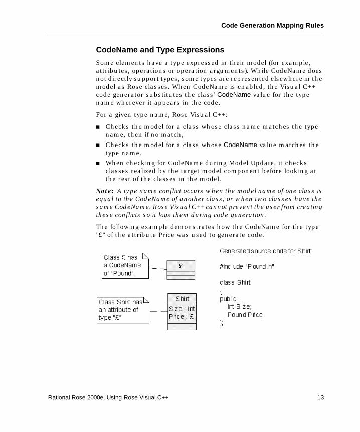
The following example demonstrates how the CodeName for the type "£" of the attribute Price was used to generate code.
Rational Rose 2000e, Using Rose Visual C++ 13
Chapter 2 Object Modeling and Visual C++
Display Parameters
When CodeName is enabled, all Rose Visual C++ dialogs generally use model names when displaying model items and code names when displaying code items. If the item has a CodeName value, that value is used when displaying the code item.
Model Assistant
The Model Assistant is used to set and modify code names. In the Model Assistant, the tree view on the left side displays model names. When CodeName is enabled, the element tabs contain a Code Name text field for entering and/or modifying the element's CodeName value.
Code Update Tool
In general, displayed in the Code Update tool are model names. The exceptions are code preview strings and error messages.
Model Update Tool
In general, all element names displayed in the Model Update tool are code names derived from the Visual C++ IDE. Model names are not available to the Model Update tool.
Visual C++ Properties Dialog
In the Visual C++ Properties dialog (Tools > Visual C++ > Properties), you can enter localized characters on the Containers, Class Operations, and Assessors tabs.
Component Properties Dialog
In the Visual C++ Component Properties dialog (right-click component, then Properties), you can enter localized characters on the Internal Map and External Map tabs.
Class CodeNames
When CodeName is active, the Model Assistant displays a Code Name text box on the model element's Class tab. The content of this box becomes the name for the code elements of the class. For example, a code name of foo results in the class being defined in foo.h and implemented in foo.cpp.
14 Rational Rose 2000e, Using Rose Visual C++
Code Generation Mapping Rules
Operation CodeNames
When CodeName is active, the Model Assistant displays a Code Name text box on the model element's Operation tab. The content of this box becomes the name for the operation's code elements. For example, a Code Name of foo results in the operation being defined and implemented as foo();
Operation Argument CodeNames
When CodeName is active, the Model Assistant displays a Code Name text box on the operation argument's Parameter tab. The content of this box becomes the name for the argument's code elements. For example, an operation with a code name of foo containing an argument (parameter) with a code name of foo1 results in the argument being defined and implemented as foo(foo1).
Attribute CodeNames
When CodeName is active, the Model Assistant displays a Code Name text box on the model element's Attribute tab. The content of this box becomes the name for the attribute's code elements. For example, a code name of int i results in the attribute being defined and implemented as int i.
Role CodeNames
When CodeName is active, the Model Assistant displays a Code Name text box on the association's Role tab. The content of this box becomes the name for the role's code elements. For example, a code name of theRole results in the role being defined and implemented as Role* theRole;
Rose Visual C++ also lets the user encode an implementation type for a role in the role name itself. For example:
theFoo // simple role name theFoo : CArray<Foo, Foo&> // Implement the role with a CArray
Note: When setting the CodeName property for a role, the property replaces only the name component of a complex (name:implementation) role name and not the implementation type part. In other words, a role CodeName does not contain a :type expression. See CodeName and Type Expressions on page 13 for more information.
Rational Rose 2000e, Using Rose Visual C++ 15
Chapter 2 Object Modeling and Visual C++
If the role is not named, and CodeName is enabled, the default role name is the<SupplierName> unless the supplier class has a CodeName value, in which case the CodeName value for the role becomes the<SupplierCodeName>.
Package CodeNames
Packages are ignored by the Visual C++ Code Update tool. However, any package in the code is preserved in the code. In addition, when importing an external component into a model, a package may be created to contain the imported model information. The CodeName property for such a package is set to the package file name (for example, import.dll).
Thus, when CodeName is active, the package CodeName property (Tools > Options > VC++ > Class Category) preserves the package file name, freeing the user to change the model name of the package without affecting the code.
CodeName and Instantiated Classes
Instantiated classes contain embedded type information. For example, a typical Rose attribute may be:
MyWidgets:Clist <Widget, Widget&>
When CodeName is enabled, Rose Visual C++ applies its type-matching algorithm to each data type encountered in instantiated classes. For example, in the following figure all portions of the instantiated class "¥§£±<Å¢®µ, Å¢®µ&>" in the Rose model were replaced by the appropriate CodeName values so the generated code becomes
16 Rational Rose 2000e, Using Rose Visual C++
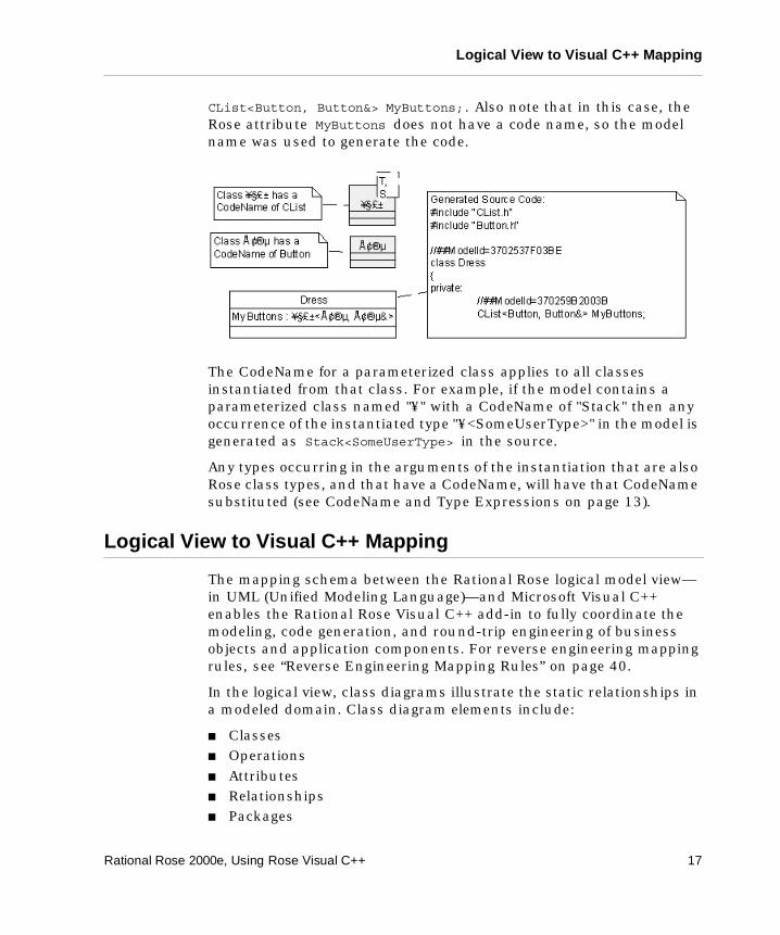
Logical View to Visual C++ Mapping
CList<Button, Button&> MyButtons; . Also note that in this case, the Rose attribute MyButtons does not have a code name, so the model name was used to generate the code.
The CodeName for a parameterized class applies to all classes instantiated from that class. For example, if the model contains a parameterized class named "¥" with a CodeName of "Stack" then any occurrence of the instantiated type "¥<SomeUserType>" in the model is generated as Stack<SomeUserType> in the source.
Any types occurring in the arguments of the instantiation that are also Rose class types, and that have a CodeName, will have that CodeName substituted (see CodeName and Type Expressions on page 13).
Logical View to Visual C++ Mapping
The mapping schema between the Rational Rose logical model view—in UML (Unified Modeling Language)—and Microsoft Visual C++ enables the Rational Rose Visual C++ add-in to fully coordinate the modeling, code generation, and round-trip engineering of business objects and application components. For reverse engineering mapping rules, see “Reverse Engineering Mapping Rules” on page 40.
In the logical view, class diagrams illustrate the static relationships in a modeled domain. Class diagram elements include:
� Classes � Operations � Attributes � Relationships � Packages
Rational Rose 2000e, Using Rose Visual C++ 17
Chapter 2 Object Modeling and Visual C++
Classes
A class is a description of a set of objects that share a common structure (attributes and relationships) as well as a common behavior (operations). The default mapping of a modeled class is to a Visual C++ class header and source file.
The stereotype of a modeled class defines the kind of Visual C++ code generated for the class.
Visual C++ supports public, private, and protected access control (scope). Therefore, each attribute, relationship, and operation in the Class Specification map to the appropriate public, private, or protected section in the generated class header.
Code Generated for Classes
For each modeled class, Rational Rose Visual C++ generates the following code constructs, as required:
� #include directives derived from model attributes and relationships.
� A class declaration, taken from the class name, type, and its generalization relationships (inheritance).
� Data members, generated from the class attributes and relationships.
� Member function declarations and skeletal member function definitions for each operation defined for the class.
� Documentation for each generated class, data member, and member function, extracted from the model item’s specification.
� An identifier, as a code comment, for each generated class, data member, and member function, which identifies the corresponding element in the model. For example: //##ModelID=3237F8CE0053
18 Rational Rose 2000e, Using Rose Visual C++
Logical View to Visual C++ Mapping
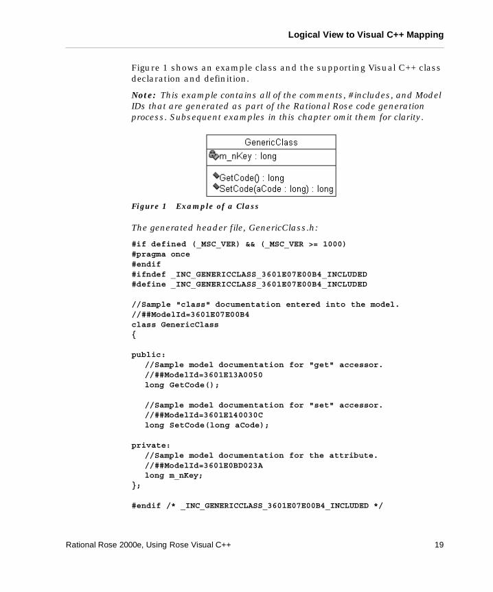
Figure 1 shows an example class and the supporting Visual C++ class declaration and definition.
Note: This example contains all of the comments, #includes, and Model IDs that are generated as part of the Rational Rose code generation process. Subsequent examples in this chapter omit them for clarity.
Figure 1 Example of a Class
The generated header file, GenericClass.h:
#if defined (_MSC_VER) && (_MSC_VER >= 1000)#pragma once#endif#ifndef _INC_GENERICCLASS_3601E07E00B4_INCLUDED#define _INC_GENERICCLASS_3601E07E00B4_INCLUDED
//Sample "class" documentation entered into the model.//##ModelId=3601E07E00B4class GenericClass {
public://Sample model documentation for "get" accessor.//##ModelId=3601E13A0050long GetCode();
//Sample model documentation for "set" accessor.//##ModelId=3601E140030Clong SetCode(long aCode);
private://Sample model documentation for the attribute.//##ModelId=3601E0BD023Along m_nKey;
};
#endif /* _INC_GENERICCLASS_3601E07E00B4_INCLUDED */
Rational Rose 2000e, Using Rose Visual C++ 19
Chapter 2 Object Modeling and Visual C++
The generated body file, GenericClass.cpp:
#include "GenericClass.h"
//##ModelId=3601E13A0050long GenericClass::GetCode(){
return (long)0;}
//##ModelId=3601E140030Clong GenericClass::SetCode(long aCode){
return (long)0;}
Class Stereotypes
The stereotype of a class helps to determine the Visual C++ code that is generated for the class. You define the stereotype on the Class tab of the Model Assistant.
If the stereotype value is empty or unknown to the Code Update tool (that is, it matches none of the values in the table below), Rational Rose generates a header (.h) and a body (.cpp) file for the class. If you want to generate a class into some other type of Visual C++ element, you must change the class stereotype.
Note: Once you generate code for a class, Visual C++ will not let you alter its implementation type.
If the Generate check box in the Model Assistant tool is unchecked for a class, Rational Rose generates no code for the class.
The following class stereotypes are used by Rational Rose when generating or reverse engineering Visual C++ code:
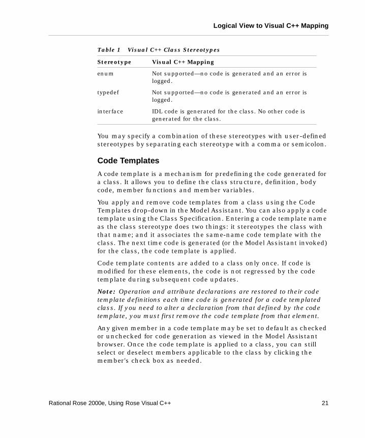
Table 1 Visual C++ Class Stereotypes
Stereotype Visual C++ Mapping
No stereotype (Default) Represents an unstereotyped class module in Visual C++.
struct Represents a struct data type in Visual C++.
union Represents a union data type in Visual C++.
20 Rational Rose 2000e, Using Rose Visual C++
Logical View to Visual C++ Mapping
You may specify a combination of these stereotypes with user-defined stereotypes by separating each stereotype with a comma or semicolon.
Code Templates
A code template is a mechanism for predefining the code generated for a class. It allows you to define the class structure, definition, body code, member functions and member variables.
You apply and remove code templates from a class using the Code Templates drop-down in the Model Assistant. You can also apply a code template using the Class Specification. Entering a code template name as the class stereotype does two things: it stereotypes the class with that name; and it associates the same-name code template with the class. The next time code is generated (or the Model Assistant invoked) for the class, the code template is applied.
Code template contents are added to a class only once. If code is modified for these elements, the code is not regressed by the code template during subsequent code updates.
Note: Operation and attribute declarations are restored to their code template definitions each time code is generated for a code templated class. If you need to alter a declaration from that defined by the code template, you must first remove the code template from that element.
Any given member in a code template may be set to default as checked or unchecked for code generation as viewed in the Model Assistant browser. Once the code template is applied to a class, you can still select or deselect members applicable to the class by clicking the member's check box as needed.
enum Not supported—no code is generated and an error is logged.
typedef Not supported—no code is generated and an error is logged.
interface IDL code is generated for the class. No other code is generated for the class.
Table 1 Visual C++ Class Stereotypes
Stereotype Visual C++ Mapping
Rational Rose 2000e, Using Rose Visual C++ 21
Chapter 2 Object Modeling and Visual C++
Only one code template at a time may be assigned to a class. However, you can simulate multiple code template assignment by assigning a code template to a class, selecting available operations and attributes for inclusion in the class, then removing the code template (without removing the selected elements) to make way for assigning a subsequent code template.
Code templates are stored as a set of plain-text code template files. Each file-set is stored in a folder of the same name as the code template, which is located under the ..\Rose2000\VC\templates folder.
You create and modify code templates through the code template files.
For details on code template file construction and application, see the Rational Rose Online Help.
Interfaces
An interface specifies the externally-visible declarations of a class and/or IDL component in a project. Rational Rose Visual C++ generates the code for an interface and its CoClass into its assigned IDL component—a component of Type MIDL and stereotype <<MIDL>> that is associated with a project file of type IDL or ODL. See “Component View to Visual C++ Mapping” on page 38 for more information.
If the modeled interface is external to the modeled project and has no implementation in the model, no code is generated for it. Modeled relationships to an interface, however, will generate code for the client-side roles.
Interfaces may be created in the model (see “Creating New COM Objects” on page 44), reverse engineered into the model, or imported via the TypeLib Importer (see “Importing COM Objects” on page 73).
Interfaces belong to the logical view, but they are displayed also on component diagrams to represent the interface to an IDL component.
22 Rational Rose 2000e, Using Rose Visual C++
Logical View to Visual C++ Mapping
COM CoClasses
CoClasses have the stereotype <<coclass>>. If they are created by importing a COM component or by the New ATL Object command, they appear as colored boxes and without the attribute and operation divisions common to a normal class model. Attributes and operations should not be added to CoClasses.
Parameterized Classes
For a parameterized class in a Visual C++ model, Rational Rose Visual C++ generates a Visual C++ template class.
Note: Rational Rose Visual C++ generates code for parameterized classes only in the class' header file. This is because parameterized classes must be instantiated in the source file that specifies its type parameter. Should existing code contain a parameterized class implementation with the declaration in the header file and the implementation in the body file, Rational Rose Visual C++ correctly reads the code into the model as a parameterized class. However, if you then modify the class in your model and generate code, Rational Rose Visual C++ only updates the header file: it will not update the body file.
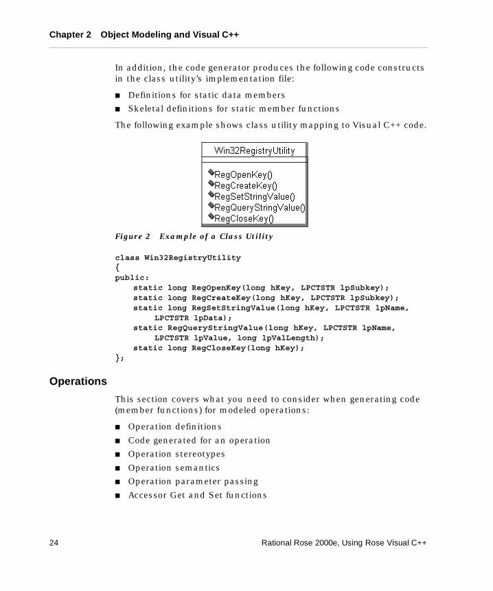
Class Utilities
A class utility class type denotes a class that only provides static data members and/or static member functions. A class utility can therefore be used to collect a set of free operations. For example, consider a collection of functions that manipulate the Windows registry. These can be gathered together into a class utility (see Figure 2).
A class utility maps to a Visual C++ module. Its properties map as public or private module variables, and the operations map as public or private module member functions.
Code Generated for Class Utilities
For each class utility, Rational Rose Visual C++ generates the following code constructs in its header file:
� The class definition, including the class name and base list
� Declarations for static member functions listed in the Class Specification
� Declarations for static data members
Rational Rose 2000e, Using Rose Visual C++ 23
Chapter 2 Object Modeling and Visual C++
In addition, the code generator produces the following code constructs in the class utility’s implementation file:
� Definitions for static data members
� Skeletal definitions for static member functions
The following example shows class utility mapping to Visual C++ code.
Figure 2 Example of a Class Utility
class Win32RegistryUtility {public:
static long RegOpenKey(long hKey, LPCTSTR lpSubkey); static long RegCreateKey(long hKey, LPCTSTR lpSubkey); static long RegSetStringValue(long hKey, LPCTSTR lpName,
LPCTSTR lpData); static RegQueryStringValue(long hKey, LPCTSTR lpName,
LPCTSTR lpValue, long lpValLength); static long RegCloseKey(long hKey);
};
Operations
This section covers what you need to consider when generating code (member functions) for modeled operations:
� Operation definitions
� Code generated for an operation
� Operation stereotypes
� Operation semantics
� Operation parameter passing
� Accessor Get and Set functions
24 Rational Rose 2000e, Using Rose Visual C++
Logical View to Visual C++ Mapping
Operation Definitions
The Rational Rose Visual C++ Operation Specification allows you to specify the following aspects of an operation:
� The operation stereotype, which determines the basic code generated for an operation. See “Operation Stereotypes” on page 26 for details on the available stereotypes.
� The Export Control field of the Operation Specification determines whether the access level (scope) of the member function is public, private, or protected. The implementation model access is mapped to private.
� The operation name. Operation names can be overloaded in Visual C++.
� Operation parameters (arguments), which are declared with a unique name and argument type.
� Documentation, which is included in the generated code as code comments.
Note: The Visual C++ code generator ignores the text on the Preconditions, Postconditions, and Semantics tabs of an Operation Specification.
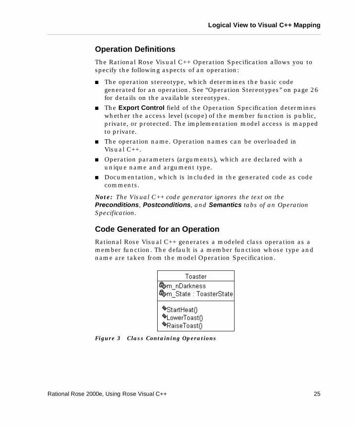
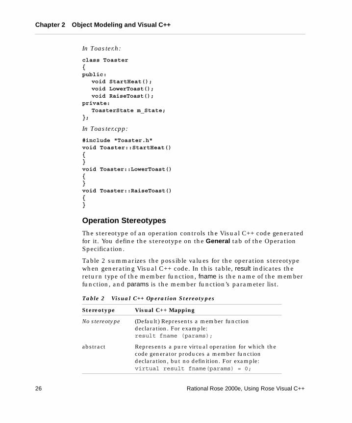
Code Generated for an Operation
Rational Rose Visual C++ generates a modeled class operation as a member function. The default is a member function whose type and name are taken from the model Operation Specification.
Figure 3 Class Containing Operations
Rational Rose 2000e, Using Rose Visual C++ 25
Chapter 2 Object Modeling and Visual C++
In Toaster.h:
class Toaster {public:
void StartHeat();void LowerToast();void RaiseToast();
private:ToasterState m_State;
};
In Toaster.cpp:
#include "Toaster.h"void Toaster::StartHeat(){}void Toaster::LowerToast(){}void Toaster::RaiseToast(){}
Operation Stereotypes
The stereotype of an operation controls the Visual C++ code generated for it. You define the stereotype on the General tab of the Operation Specification.
Table 2 summarizes the possible values for the operation stereotype when generating Visual C++ code. In this table, result indicates the return type of the member function, fname is the name of the member function, and params is the member function’s parameter list.
Table 2 Visual C++ Operation Stereotypes
Stereotype Visual C++ Mapping
No stereotype (Default) Represents a member function declaration. For example:result fname (params);
abstract Represents a pure virtual operation for which the code generator produces a member function declaration, but no definition. For example:virtual result fname(params) = 0;
26 Rational Rose 2000e, Using Rose Visual C++
Logical View to Visual C++ Mapping
Operation Semantics
The operation semantics, as specified on the Semantics tab of the Operation Specification, are ignored by the Visual C++ code generator.
Operation Parameter Passing
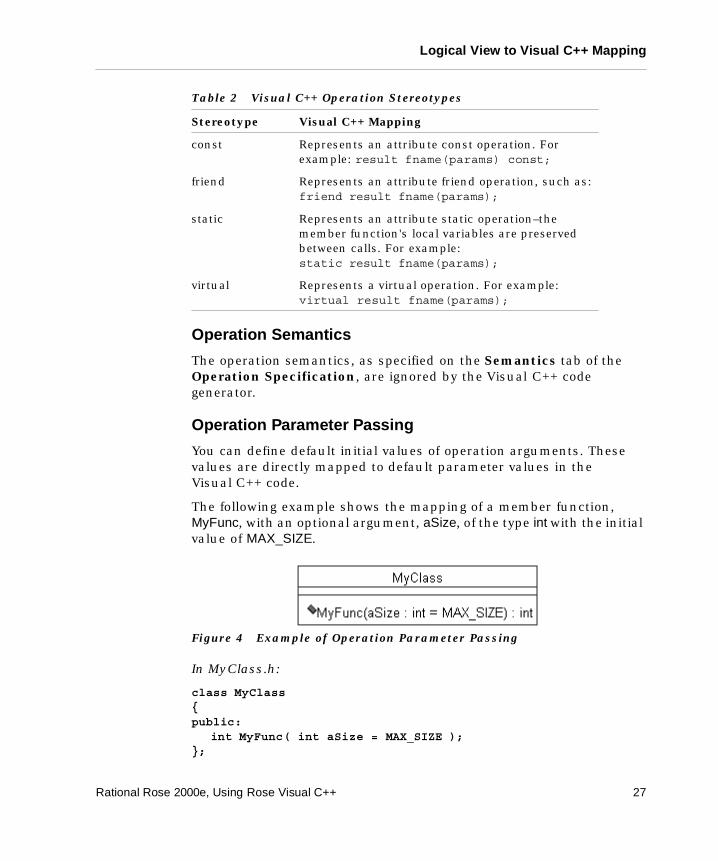
You can define default initial values of operation arguments. These values are directly mapped to default parameter values in the Visual C++ code.
The following example shows the mapping of a member function, MyFunc, with an optional argument, aSize, of the type int with the initial value of MAX_SIZE.
Figure 4 Example of Operation Parameter Passing
In MyClass.h:
class MyClass {public:
int MyFunc( int aSize = MAX_SIZE );};
const Represents an attribute const operation. For example: result fname(params) const;
friend Represents an attribute friend operation, such as: friend result fname(params);
static Represents an attribute static operation–the member function's local variables are preserved between calls. For example: static result fname(params);
virtual Represents a virtual operation. For example: virtual result fname(params);
Table 2 Visual C++ Operation Stereotypes
Stereotype Visual C++ Mapping
Rational Rose 2000e, Using Rose Visual C++ 27
Chapter 2 Object Modeling and Visual C++
Accessor Get and Set Functions
Rational Rose Visual C++ offers accessor Get and Set functions through the Model Assistant tool. The Model Assistant treeview automatically lists a Get and a Set function for each attribute and association in the model.
However, an accessor function is not loaded into the model until it is selected and the Apply button is clicked. You set accessor function properties on the Accessor Get or Accessor Set tabs, as appropriate.
The attribute or association name is reflected in the default names of their Get and Set functions. When you change the name of an attribute or association, a dialog box prompts you to change the names of its Get and Set functions as well.
Attributes
An attribute represents a data member in Visual C++. If an attribute is an object, it should be modeled as an association to the corresponding object class.
For each generated member, Rational Rose Visual C++ adds any documentation from the Attribute Specification as code comments.
Note: You can use the Model Assistant tool to automatically create accessor functions for attributes in the model. See “Accessor Get and Set Functions” on page 28.
Code Generated for Attributes
By default, a class attribute is represented in code as a data member. The generated default code is a data member whose type and name is taken from the Attribute Specification in the model. By specifying additional information in the attribute name and type, pointers, arrays, and references can also be generated. See “Pointers, Arrays, and References in Visual C++” on page 36.
28 Rational Rose 2000e, Using Rose Visual C++
Logical View to Visual C++ Mapping
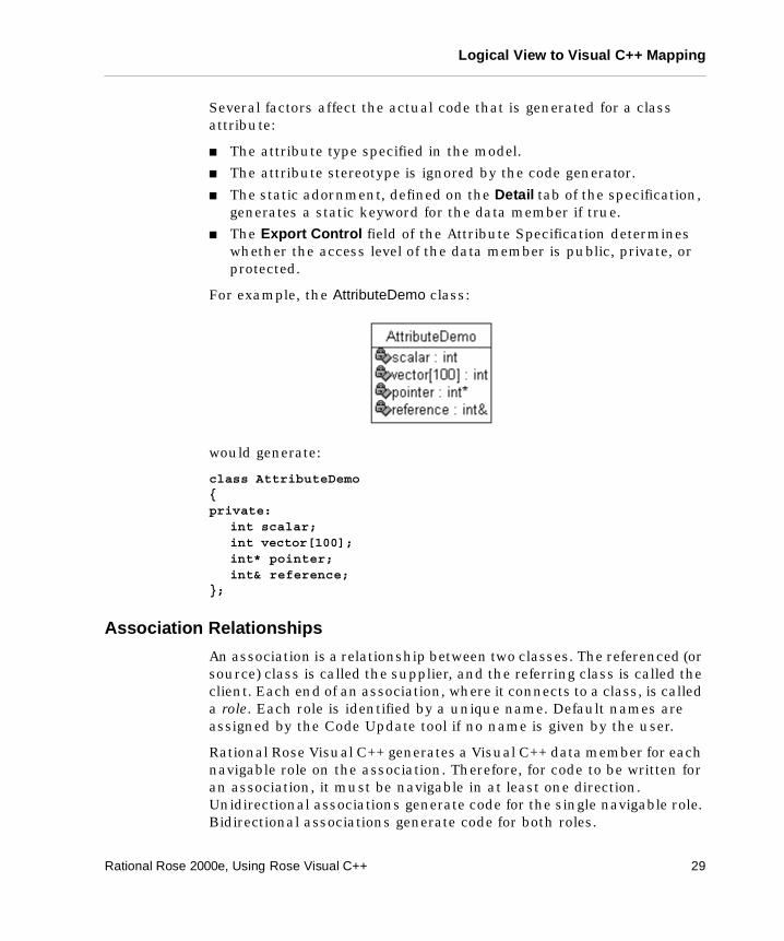
Several factors affect the actual code that is generated for a class attribute:
� The attribute type specified in the model.
� The attribute stereotype is ignored by the code generator.
� The static adornment, defined on the Detail tab of the specification, generates a static keyword for the data member if true.
� The Export Control field of the Attribute Specification determines whether the access level of the data member is public, private, or protected.
For example, the AttributeDemo class:
would generate:
class AttributeDemo {private:
int scalar;int vector[100];int* pointer;int& reference;
};
Association Relationships
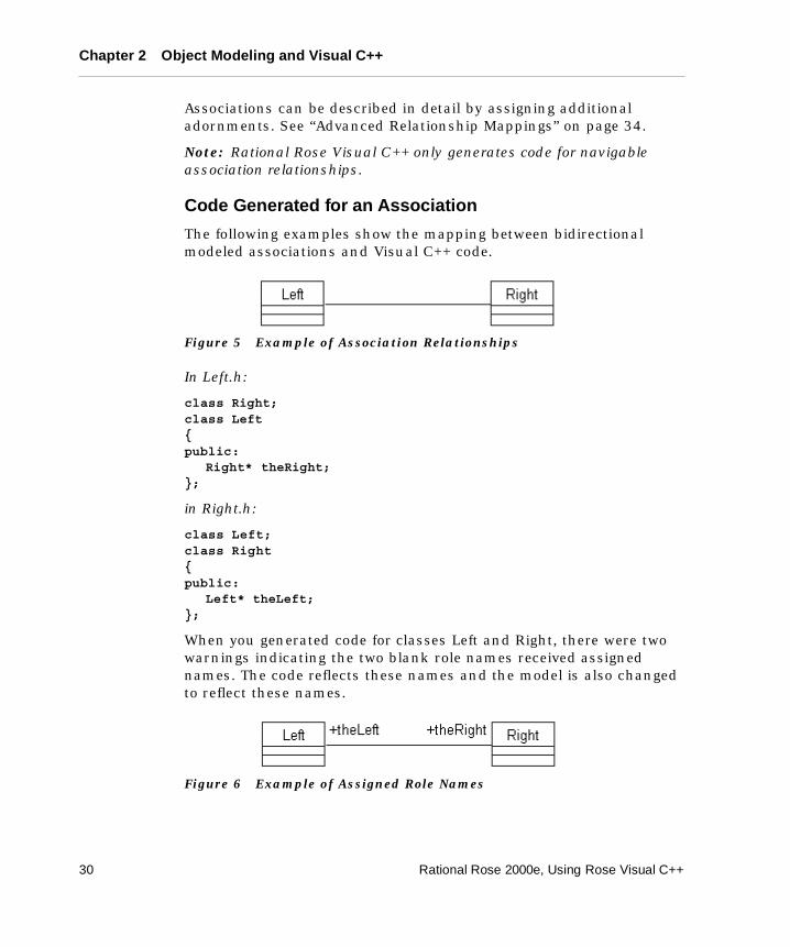
An association is a relationship between two classes. The referenced (or source) class is called the supplier, and the referring class is called the client. Each end of an association, where it connects to a class, is called a role. Each role is identified by a unique name. Default names are assigned by the Code Update tool if no name is given by the user.
Rational Rose Visual C++ generates a Visual C++ data member for each navigable role on the association. Therefore, for code to be written for an association, it must be navigable in at least one direction. Unidirectional associations generate code for the single navigable role. Bidirectional associations generate code for both roles.
Rational Rose 2000e, Using Rose Visual C++ 29
Chapter 2 Object Modeling and Visual C++
Associations can be described in detail by assigning additional adornments. See “Advanced Relationship Mappings” on page 34.
Note: Rational Rose Visual C++ only generates code for navigable association relationships.
Code Generated for an Association
The following examples show the mapping between bidirectional modeled associations and Visual C++ code.
Figure 5 Example of Association Relationships
In Left.h:
class Right;class Left {public:
Right* theRight;};
in Right.h:
class Left;class Right {public:
Left* theLeft;};
When you generated code for classes Left and Right, there were two warnings indicating the two blank role names received assigned names. The code reflects these names and the model is also changed to reflect these names.
Figure 6 Example of Assigned Role Names
30 Rational Rose 2000e, Using Rose Visual C++
Logical View to Visual C++ Mapping
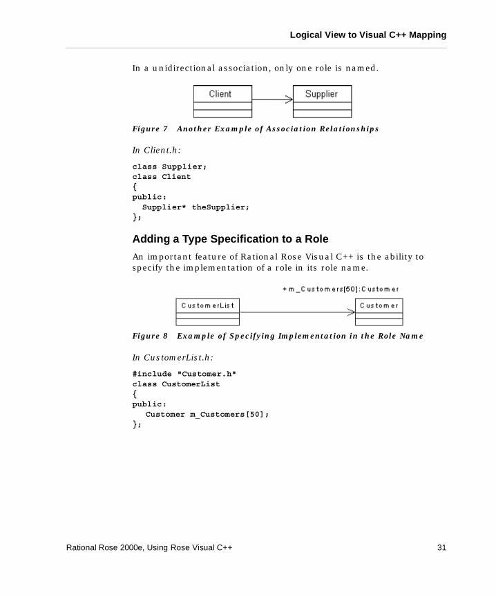
In a unidirectional association, only one role is named.
Figure 7 Another Example of Association Relationships
In Client.h:
class Supplier;class Client{public: Supplier* theSupplier;};
Adding a Type Specification to a Role
An important feature of Rational Rose Visual C++ is the ability to specify the implementation of a role in its role name.
Figure 8 Example of Specifying Implementation in the Role Name
In CustomerList.h:
#include "Customer.h"class CustomerList {public:
Customer m_Customers[50];};
Rational Rose 2000e, Using Rose Visual C++ 31
Chapter 2 Object Modeling and Visual C++
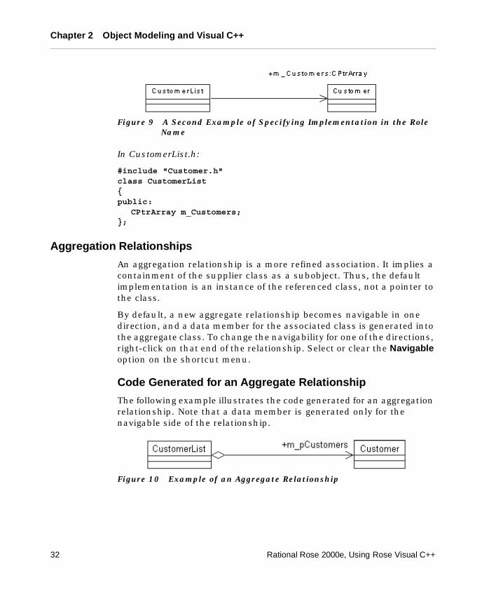
Figure 9 A Second Example of Specifying Implementation in the Role Name
In CustomerList.h:
#include "Customer.h"class CustomerList {public:
CPtrArray m_Customers;};
Aggregation Relationships
An aggregation relationship is a more refined association. It implies a containment of the supplier class as a subobject. Thus, the default implementation is an instance of the referenced class, not a pointer to the class.
By default, a new aggregate relationship becomes navigable in one direction, and a data member for the associated class is generated into the aggregate class. To change the navigability for one of the directions, right-click on that end of the relationship. Select or clear the Navigable option on the shortcut menu.
Code Generated for an Aggregate Relationship
The following example illustrates the code generated for an aggregation relationship. Note that a data member is generated only for the navigable side of the relationship.
Figure 10 Example of an Aggregate Relationship
32 Rational Rose 2000e, Using Rose Visual C++
Logical View to Visual C++ Mapping
In CustomerList.h:
#include "Customer.h"class CustomerList {public:
Customer m_pCustomers;};
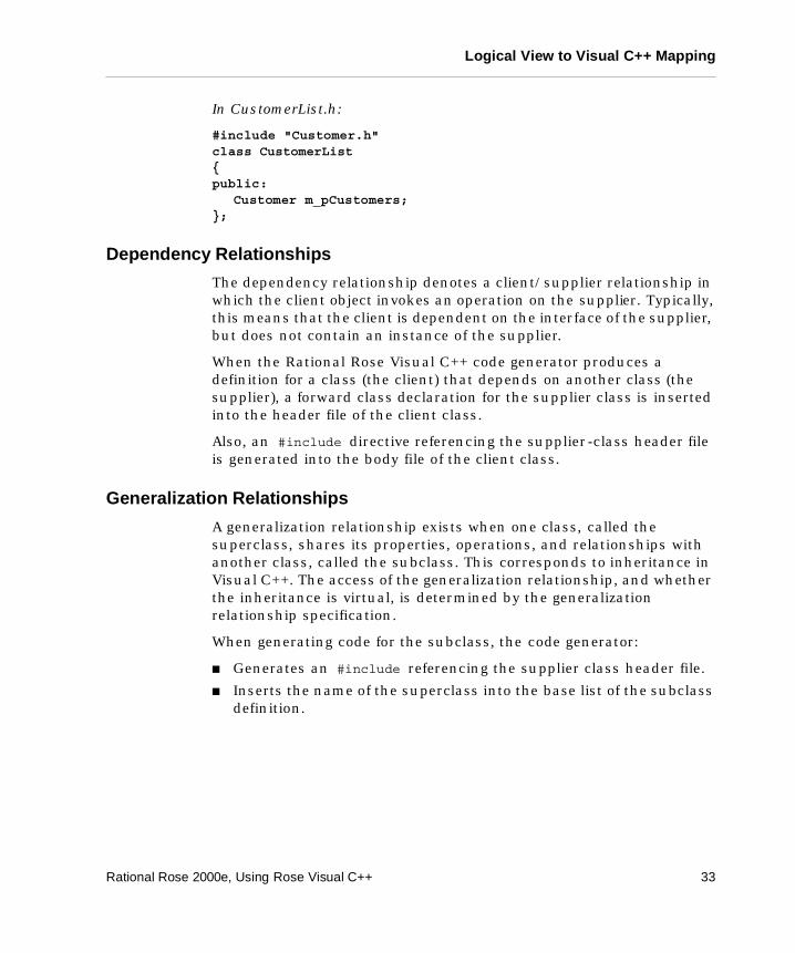
Dependency Relationships
The dependency relationship denotes a client/supplier relationship in which the client object invokes an operation on the supplier. Typically, this means that the client is dependent on the interface of the supplier, but does not contain an instance of the supplier.
When the Rational Rose Visual C++ code generator produces a definition for a class (the client) that depends on another class (the supplier), a forward class declaration for the supplier class is inserted into the header file of the client class.
Also, an #include directive referencing the supplier-class header file is generated into the body file of the client class.
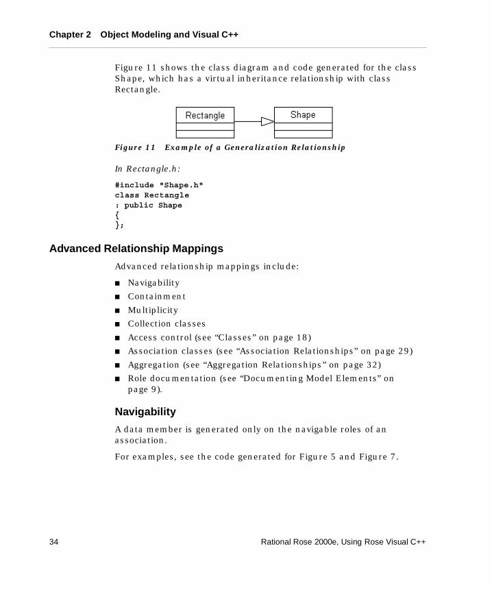
Generalization Relationships
A generalization relationship exists when one class, called the superclass, shares its properties, operations, and relationships with another class, called the subclass. This corresponds to inheritance in Visual C++. The access of the generalization relationship, and whether the inheritance is virtual, is determined by the generalization relationship specification.
When generating code for the subclass, the code generator:
� Generates an #include referencing the supplier class header file.
� Inserts the name of the superclass into the base list of the subclass definition.
Rational Rose 2000e, Using Rose Visual C++ 33
Chapter 2 Object Modeling and Visual C++
Figure 11 shows the class diagram and code generated for the class Shape, which has a virtual inheritance relationship with class Rectangle.
Figure 11 Example of a Generalization Relationship
In Rectangle.h:
#include "Shape.h"class Rectangle : public Shape{};
Advanced Relationship Mappings
Advanced relationship mappings include:
� Navigability
� Containment
� Multiplicity
� Collection classes
� Access control (see “Classes” on page 18)
� Association classes (see “Association Relationships” on page 29)
� Aggregation (see “Aggregation Relationships” on page 32)
� Role documentation (see “Documenting Model Elements” on page 9).
Navigability
A data member is generated only on the navigable roles of an association.
For examples, see the code generated for Figure 5 and Figure 7.
34 Rational Rose 2000e, Using Rose Visual C++
Logical View to Visual C++ Mapping
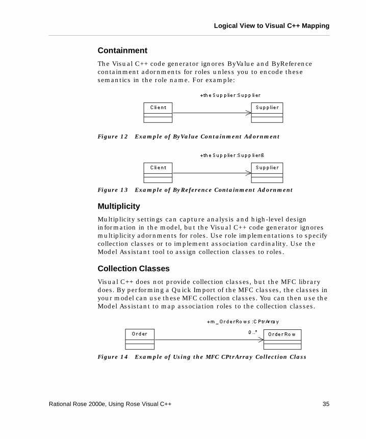
Containment
The Visual C++ code generator ignores ByValue and ByReference containment adornments for roles unless you to encode these semantics in the role name. For example:
Figure 12 Example of ByValue Containment Adornment
Figure 13 Example of ByReference Containment Adornment
Multiplicity
Multiplicity settings can capture analysis and high-level design information in the model, but the Visual C++ code generator ignores multiplicity adornments for roles. Use role implementations to specify collection classes or to implement association cardinality. Use the Model Assistant tool to assign collection classes to roles.
Collection Classes
Visual C++ does not provide collection classes, but the MFC library does. By performing a Quick Import of the MFC classes, the classes in your model can use these MFC collection classes. You can then use the Model Assistant to map association roles to the collection classes.
Figure 14 Example of Using the MFC CPtrArray Collection Class
Rational Rose 2000e, Using Rose Visual C++ 35
Chapter 2 Object Modeling and Visual C++
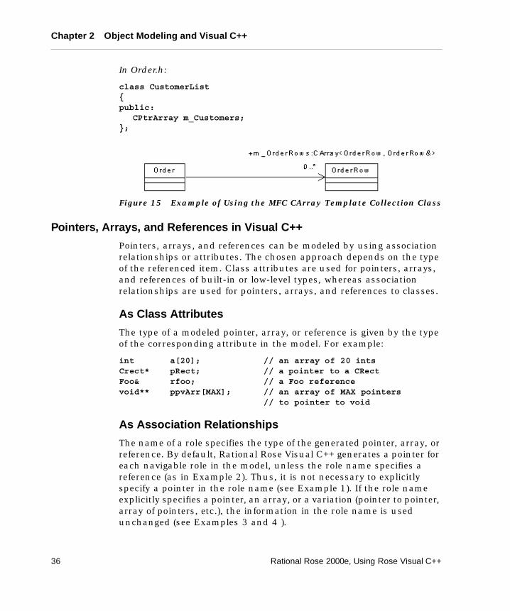
In Order.h:
class CustomerList {public:
CPtrArray m_Customers;};
Figure 15 Example of Using the MFC CArray Template Collection Class
Pointers, Arrays, and References in Visual C++
Pointers, arrays, and references can be modeled by using association relationships or attributes. The chosen approach depends on the type of the referenced item. Class attributes are used for pointers, arrays, and references of built-in or low-level types, whereas association relationships are used for pointers, arrays, and references to classes.
As Class Attributes
The type of a modeled pointer, array, or reference is given by the type of the corresponding attribute in the model. For example:
int a[20]; // an array of 20 intsCrect* pRect; // a pointer to a CRectFoo& rfoo; // a Foo referencevoid** ppvArr[MAX]; // an array of MAX pointers
// to pointer to void
As Association Relationships
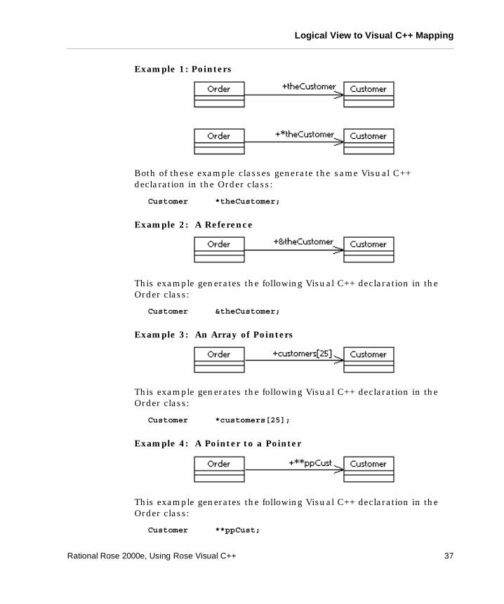
The name of a role specifies the type of the generated pointer, array, or reference. By default, Rational Rose Visual C++ generates a pointer for each navigable role in the model, unless the role name specifies a reference (as in Example 2). Thus, it is not necessary to explicitly specify a pointer in the role name (see Example 1). If the role name explicitly specifies a pointer, an array, or a variation (pointer to pointer, array of pointers, etc.), the information in the role name is used unchanged (see Examples 3 and 4 ).
36 Rational Rose 2000e, Using Rose Visual C++
Logical View to Visual C++ Mapping
Example 1: Pointers
Both of these example classes generate the same Visual C++ declaration in the Order class:
Customer *theCustomer;
Example 2: A Reference
This example generates the following Visual C++ declaration in the Order class:
Customer &theCustomer;
Example 3: An Array of Pointers
This example generates the following Visual C++ declaration in the Order class:
Customer *customers[25];
Example 4: A Pointer to a Pointer
This example generates the following Visual C++ declaration in the Order class:
Customer **ppCust;
Rational Rose 2000e, Using Rose Visual C++ 37
Chapter 2 Object Modeling and Visual C++
Packages
A package is a logical collection of classes and/or other packages that represents an architectural subsystem of the modeled application. Each package declares its dependencies to other packages using a dependency diagram. Packages have no direct mapping to Visual C++ code, so no code is generated for them.
Component View to Visual C++ Mapping
Components in the model represent the software projects that together realize the modeled system. To generate Visual C++ code for a class, that class must be assigned to one or more Visual C++ components. The Component Specification defines the component’s implementation language and its stereotype (executable, data link library, interface definition language, etc.).
The physical instantiation of a component is the .exe, .dll, .tlb, .idl, .odl, or .ocx file generated from the corresponding Visual C++ project. A component can only be related to one project, and the name and path of that project file is stored in the component’s ProjectFile model property.
38 Rational Rose 2000e, Using Rose Visual C++
Component View to Visual C++ Mapping
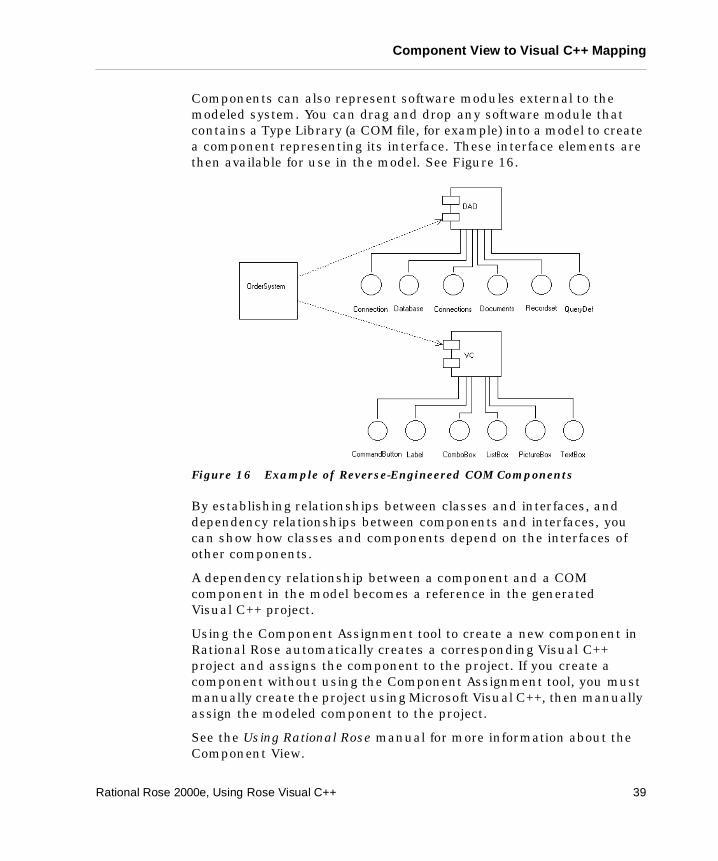
Components can also represent software modules external to the modeled system. You can drag and drop any software module that contains a Type Library (a COM file, for example) into a model to create a component representing its interface. These interface elements are then available for use in the model. See Figure 16.
Figure 16 Example of Reverse-Engineered COM Components
By establishing relationships between classes and interfaces, and dependency relationships between components and interfaces, you can show how classes and components depend on the interfaces of other components.
A dependency relationship between a component and a COM component in the model becomes a reference in the generated Visual C++ project.
Using the Component Assignment tool to create a new component in Rational Rose automatically creates a corresponding Visual C++ project and assigns the component to the project. If you create a component without using the Component Assignment tool, you must manually create the project using Microsoft Visual C++, then manually assign the modeled component to the project.
See the Using Rational Rose manual for more information about the Component View.
Rational Rose 2000e, Using Rose Visual C++ 39
Chapter 2 Object Modeling and Visual C++
Component Stereotypes
The component stereotype indicates the type of the component’s Visual C++ project (.dll or .exe). The component stereotype setting on the Component Specification is not used by the Visual C++ add-in, however, it is correctly set as a consequence of assigning a project to the component using the Component Assignment tool.
Deployment View to Visual C++ Mapping
Rational Rose Visual C++ does not currently support code generation from the Deployment View.
See the Using Rational Rose manual for more information about the Deployment View.
Reverse Engineering Mapping Rules
This section describes the mapping schema between a Microsoft Visual C++ application and a Rational Rose model. This schema is used during reverse engineering.
Note: If your Visual C++ project contains conditional compiler directives, the reverse engineering applies only to those declarations that are visible under the current conditions.
Table 3 Visual C++ Component Stereotypes
Stereotype Visual C++ Mapping
DLL Represents a Visual C++ project of the type Win32 Dynamic-Link Library. DLL projects can be both generated and reverse engineered.
EXE Represents a Visual C++ project of the type Win32 Application. EXE projects can be both generated and reverse engineered.
40 Rational Rose 2000e, Using Rose Visual C++
Reverse Engineering Mapping Rules
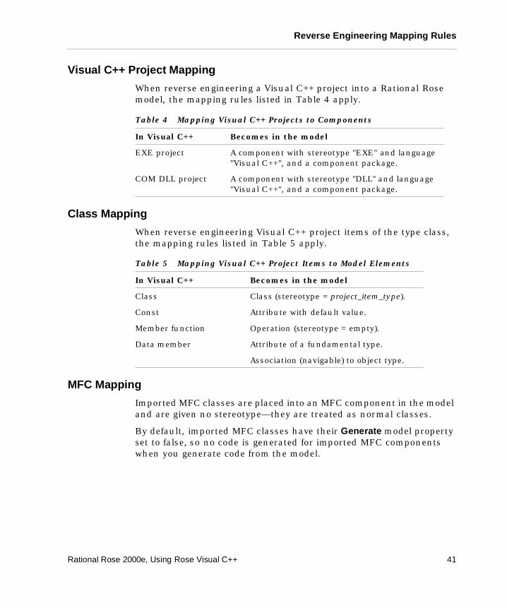
Visual C++ Project Mapping
When reverse engineering a Visual C++ project into a Rational Rose model, the mapping rules listed in Table 4 apply.
Class Mapping
When reverse engineering Visual C++ project items of the type class, the mapping rules listed in Table 5 apply.
MFC Mapping
Imported MFC classes are placed into an MFC component in the model and are given no stereotype—they are treated as normal classes.
By default, imported MFC classes have their Generate model property set to false, so no code is generated for imported MFC components when you generate code from the model.
Table 4 Mapping Visual C++ Projects to Components
In Visual C++ Becomes in the model
EXE project A component with stereotype "EXE" and language "Visual C++", and a component package.
COM DLL project A component with stereotype "DLL" and language "Visual C++", and a component package.
Table 5 Mapping Visual C++ Project Items to Model Elements
In Visual C++ Becomes in the model
Class Class (stereotype = project_item_type).
Const Attribute with default value.
Member function Operation (stereotype = empty).
Data member Attribute of a fundamental type.
Association (navigable) to object type.
Rational Rose 2000e, Using Rose Visual C++ 41
Chapter 2 Object Modeling and Visual C++
COM Object Mapping
A COM object is modeled as a set of related ATL classes with specific stereotypes and relationships. At minimum, an ATL object consists of an <<atlobject>> class, a CoClass, and one or more interfaces. A dependency relationship exists between the <<atlobject>> class and the CoClass, and a realizes relationship exists between the CoClass and the Interface.
To expand a class or an interface into an ATL object, simply right-click on the class (or interface), click COM > New ATL Object, and follow the process outlined in “Creating New COM Objects” on page 44.
For a modeled class, this command creates the <<coclass>>, <<interface>>, and IDispatch and CCom classes in the model, along with their relationships, and applies an <<atlobject>> stereotype to the selected (implementation) class.
For a modeled <<interface>> class, this command creates the <<coclass>> and implementation classes in the model, and relates them to each other and to the selected <<interface>> class.
Note: CoClasses have the stereotype <<coclass>>. If they are created by importing a COM component or by the New ATL Object command, they appear as colored boxes and without the attribute and operation divisions common to a normal class model. Attributes and operations should not be added to CoClasses.
Within a modeled COM class structure, the <<interface>> class is the reference. Methods and properties exposed by an interface are therefore modeled in the <<interface>> class. But because only IDL code is generated for an interface, these methods and properties are also modeled as operations and attributes, respectively, in the <<atlobject>> class, where they are implemented.
To maintain synchronization between the exposed interface methods and their implemented operations, the Implement Interfaces command (right-click on the <<interface>> class and click COM > Implement Interfaces) reads the methods in the selected <<interface>> class and implements them as operations in its <<atlobject>> class.
Note: The Implement Interfaces command is automatically performed when you invoke the Code Update tool.
42 Rational Rose 2000e, Using Rose Visual C++
Reverse Engineering Mapping Rules
Operations and attributes that are not visible to the <<interface>> class may be required for its implementation. For this reason, operations and attributes that are modeled in the <<atlobject>> (implementation) class, and changes made to them, are not copied to the <<interface>> class by the Implement Interfaces command.
Rational Rose Visual C++ represents COM methods and properties as operations in an <<interface>> class. Rational Rose requires that arguments to these operations must be written using UML syntax.
The Attributes COM model properties allow you to include IDL attributes in the arguments for these operations. For example, to the modeled <<interface>> class operation:
Func (arg1:int, arg2:int*)
set the value of the arg1 Attributes property to in and set the value of the arg2 Attributes property to out, retval to generate the following IDL code for the operation:
Func ([in]int arg1, [out, retval] int* arg2)
When generating code, Rose Visual C++ encloses the Attributes values in square brackets in conformance with COM syntax. for more information on this process, see “Adding IDL Attributes to <<interface>> Method Arguments” on page 47.
When reverse engineering a COM project (.dll, .exe, etc.), only the interface classes listed in a Type Library or MIDL file are imported into the model and placed into a component of the same name (one component per MIDL file). These interface classes receive an <<interface>> stereotype. The Full Import option also imports the methods for each interface class, the Quick Import option does not.
Code generated for an <<atlobject>> class contains a reference to its library. If an <<interface>> class is not assigned to a component, this reference in a code preview is written as ##LIBRARY##. When the class is assigned to a component, this reference is corrected.
Special help is available for ATL objects by right-clicking on the class and clicking How Do I.
Rational Rose 2000e, Using Rose Visual C++ 43
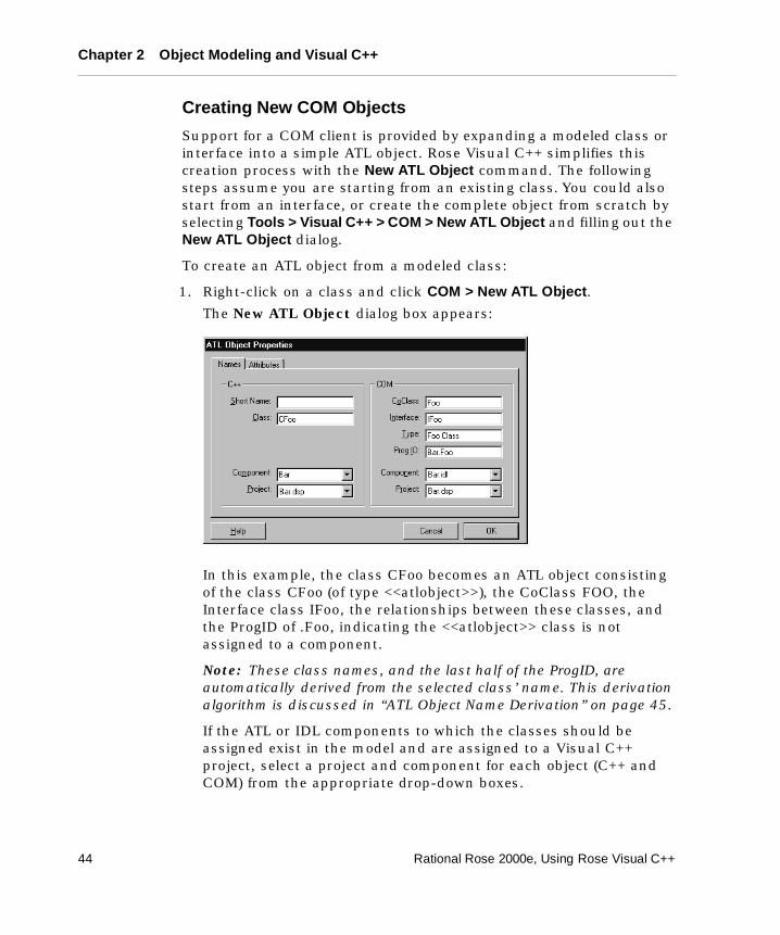
Chapter 2 Object Modeling and Visual C++
Creating New COM Objects
Support for a COM client is provided by expanding a modeled class or interface into a simple ATL object. Rose Visual C++ simplifies this creation process with the New ATL Object command. The following steps assume you are starting from an existing class. You could also start from an interface, or create the complete object from scratch by selecting Tools > Visual C++ > COM > New ATL Object and filling out the New ATL Object dialog.
To create an ATL object from a modeled class:
1. Right-click on a class and click COM > New ATL Object.
The New ATL Object dialog box appears:
In this example, the class CFoo becomes an ATL object consisting of the class CFoo (of type <<atlobject>>), the CoClass FOO, the Interface class IFoo, the relationships between these classes, and the ProgID of .Foo, indicating the <<atlobject>> class is not assigned to a component.
Note: These class names, and the last half of the ProgID, are automatically derived from the selected class’ name. This derivation algorithm is discussed in “ATL Object Name Derivation” on page 45.
If the ATL or IDL components to which the classes should be assigned exist in the model and are assigned to a Visual C++ project, select a project and component for each object (C++ and COM) from the appropriate drop-down boxes.
44 Rational Rose 2000e, Using Rose Visual C++
Reverse Engineering Mapping Rules
Note: Unless the Visual C++ and IDL components exist and are assigned to Visual C++ projects, you are encouraged to leave the Component and Project fields blank at this time. Creating new components and assigning classes and projects is best done through the Model Update tool.
2. Click OK to create the ATL object and return to your model.
For information on how the object names are derived, see ATL Object Name Derivation.
On the Attribute tab, Custom specifies that the object supports a custom interface (its vtable has custom interface functions). A custom interface can be faster than a dual interface, especially across process boundaries. Dual specifies that the object supports a dual interface (its vtable has custom interface functions plus late-binding iDispatch methods). Dual allows both COM clients and Automation controllers to access the object.
The Implement Interface command (right-click on an <<interface>> class and click COM > Implement Interfaces) takes the methods in an <<interface>> class and implements them in its <<atlobject>> class.
ATL Object Name Derivation
Object names on the Name tab of the ATL Object Properties dialog can be edited to suit, but are normally derived using one of three methods:
1. Display the Name tab by clicking Tools > Visual C++ > COM > New ATL Object (without selecting a class or interface), and all names on the tab are blank. Names are derived from the Short Name you enter, as follows:
❑ The Class name is the Short Name prefaced with the value of AltClassPrefix. The default value is "C".
❑ The Interface name is the Short Name prefaced with the value of AtlInterfacePrefix. The default value is "I".
❑ The CoClass name, the class name portion of the Type, and the last half of the ProgID match the Short Name.
❑ The Type name equals the Class name, followed by a space, followed by the value of AltTypeDescription. The default value is "Class".
Rational Rose 2000e, Using Rose Visual C++ 45
Chapter 2 Object Modeling and Visual C++
❑ The ProgID is constructed as <C++componentname>.<classname>. When you enter a Visual C++ component name in the C++ Component box, that name is automatically inserted into the front half of the ProgID. If the C++ Component box is [none], the ProgID is .<classname>.
Note: Any name (other than Short Name) you individually edit is preserved—it is not modified by the derivation process.
2. Display the Name tab by right-clicking on a class, then clicking COM > New ATL Object, and all other ATL object names derive from that Class name, as follows:
❑ The Class name is the selected class' name. If the class name includes the prefix indicated by the value of AltClassPrefix, that prefix is ignored when deriving the other ATL object names. The default prefix is "C".
❑ The CoClass name equals the Class name, minus the prefix.
❑ The Interface name equals the Class name, minus the prefix, and prefaced with the value of AtlInterfacePrefix. The default prefix is "I".
❑ The ProgID is constructed as <C++componentname>.<classname>. If the selected class is assigned to a component, that component name is automatically inserted into the front half of the ProgID. If the class is not assigned to a component, the ProgID is .<classname>.
❑ The default Short Name is blank. If you enter a value in this box, all name values are derived as in method #1.
3. Display the Name tab by right-clicking an interface, then clicking COM > New ATL Object, and all other ATL object names derive from that Interface name, as follows:
❑ The Interface name is the selected interface's name. If the Interface name includes the prefix indicated by the value of AtlInterfacePrefix, that prefix is ignored when deriving the other ATL object names. The default prefix is "I".
❑ The Class name is the selected interface's name, minus the prefix and prefaced with the value of AltClassPrefix. The default prefix is "C".
❑ All other names derive from the class name as in method #2.
46 Rational Rose 2000e, Using Rose Visual C++
Reverse Engineering Mapping Rules
Adding IDL Attributes to <<interface>> Method Arguments
Rational Rose Visual C++ represents COM methods and properties as operations in an <<interface>> class. Rational Rose requires that arguments to these operations must be written using UML syntax.
The Attributes COM model properties allow you to include IDL attributes in the arguments for <<interface>> class operations, which represent COM methods and properties in a model.
For example, to the modeled <<interface>> class operation:
Func (arg1:int, arg2:int*)
set the value of the arg1 Attributes property to in and set the value of the arg2 Attributes property to out, retval to generate the following IDL code for the operation:
Func ([in]int arg1, [out, retval] int* arg2)
When generating code, Rose Visual C++ encloses the Attributes values in square brackets in conformance with COM syntax.
The COM attributes are found on the standard Rose Specification for the item under the “COM” tab. The most important COM attributes are named properties in Rose. The others are collected under the attributes keyword.
Code Comments Mapping
Rational Rose Visual C++ reverse engineers code comments by inserting them into the documentation fields for the corresponding modeled objects.
For each declaration in the Visual C++ code, Rational Rose Visual C++ copies the directly preceding comment into the Documentation box in the corresponding model specification. There cannot be more than one empty space between the code comment and the body. Thus, you must be careful where you place your comments so that they appear in the correct model component.
Example:
/* This comment is inserted into the documentation field of Purchaser. */{Customer Purchaser( );
Purchaser = pPurchaser; }
Rational Rose 2000e, Using Rose Visual C++ 47
Chapter 2 Object Modeling and Visual C++
// This comment is not reverse engineered because there are two // empty rows between the comment and the code.
{Customer Purchaser( ); /* This comment is not reverse engineered because it follows its code. */
}
Aggregation Relationships
Unless otherwise specified, Rational Rose Visual C++ preserves default implementations across code-generation and reverse engineering cycles. That is, on code generation, simple roles are generated using the default implementation. When reverse engineering the role, if the code implementation is still the default implementation, then the role is reverse-engineered using the default form. For example, if the code contains:
B theB; //modelID=uid of role in model
then the role is reversed as theB rather than theB : B.
The Three-Tiered Model
The Rational Rose Three-Tier Diagram option offers a structured approach to facilitate the development of large, complex client/server applications. This structure segregates the services provided by an application into three tiers: user services, business services, and data services. Each tier contains service packages defining the required service behavior. Finally, classes and other objects, within each package, model the required functionality.
From a Visual C++ programming language perspective, this three-tiered structure is just another model. To properly implement an application within a three-tiered environment, you must manually segregate the modeled objects into multiple projects (components), and then assign the relevant classes into these projects.
48 Rational Rose 2000e, Using Rose Visual C++
Chapter 3
Round-Trip Engineering
Round-trip engineering is the Rational Rose Visual C++ term for a controlled, iterative, application development process. It allows you to rapidly develop a model of an application, analyzing and refining it as you increase your understanding of its operation, then automatically generate the code elements of a complete Visual C++ application framework based on that model.
You then evolve this generated code, using Visual C++, until you achieve the required functionality for the iteration. Finally, Rose Visual C++ facilitates reverse engineering your modified code structures back into the model—keeping model and code fully synchronized—to produce an updated version of the model.
The round-trip engineering tools in Rose Visual C++ are tightly integrated with the Microsoft Visual C++ environment, allowing you to seamlessly progress through the round-trip engineering process. These tool include:
� The Code Update tool – generates and updates the Visual C++ source code from the information contained in a model.
� The Model Update tool – extracts design information from the Visual C++ code and generates or updates a model representing the system’s design.
� The Model Assistant gives a quick and easy way to add new classes to your model or to change existing ones, or to add member functions and data members to your classes. It also lets you add Windows message handlers and MFC overrides to your MFC classes.
Rational Rose 2000e, Using Rose Visual C++ 49
Chapter 3 Round-Trip Engineering
The recommended approach to application development is to use Rational Rose Visual C++ to develop an object model of your system. Then use the Model Assistant to detail class designs. Use the Code Update tool to generate the skeleton header and source files for your classes. Use Microsoft Visual C++ to code the implementation. And finally, use the Model Update tool to incorporate the code modifications into your model.
Figure 17 illustrates the overall Rational Rose model-centric process.
Figure 17 The Round-Trip Engineering Process
Because the real world frequently disallows ideal practices, many application development tasks begin with an existing body of Visual C++ code, which is then reverse engineered into a Rose Visual C++ model. The round-trip engineering process is totally compatible with this approach (see “Round-Trip Engineering, Starting with a Visual C++ Project” on page 54).
It is critically important to remember that the model and the code must remain synchronized for the reverse engineering process to be fully effective.
For this reason, if you modify your application code using Visual C++, do not modify your model without first running the Model Update tool. Conversely, if you modify your model using Rational Rose, do not modify the code without first running the Code Update tool. Modifying both code and model without synchronizing the changes through the appropriate update tool, especially if you rename or delete classes, members, and methods, may cause you to lose some of your changes.
50 Rational Rose 2000e, Using Rose Visual C++
Round-Trip Engineering a Visual C++ Project
Round-Trip Engineering a Visual C++ Project
This process assumes you are creating a new application, but that you are using some existing Visual C++ source code. The process includes:
� Creating a model, including:
❑ Importing MFC and other libraries into the model.
❑ Reverse-engineering your existing source code into the model.
� Evolving your code.
� Updating your model.
To Create and develop your model:
1. Create a new model. See “Creating a New Model” on page 56.
2. If your application uses Microsoft Foundation Classes, then add them to your model (Tools > Visual C++ > Quick Import MFC 6.0). This allows you to form subclasses and other relations to the MFC classes.
3. If your application references DLLs or other executables containing type libraries, add the interfaces to these externals to your model. For more information, see the Type Library Importer chapter in the Using Rose manual.
4. Incorporate your Visual C++ project into the model with the Model Update tool (Tools > Visual C++ > Update Model). This wizard walks you through the process of adding an existing Visual C++ project to your model. When you are done, the model contains a component that represents your Visual C++ project.
5. Use Rational Rose Visual C++ to elaborate the object design of your system. Use the Model Assistant (Tools > Visual C++ > Model Assistant, or right-click on a class and click Model Assistant) to add new classes to your model or to change existing classes. Model Assistant makes it easy to add member functions and data members to your classes. It also lets you add Windows message handlers and MFC overrides to your MFC classes. Another tip is to take advantage of the Documentation field in the model—your model documentation is automatically carried forward into your code as code comments.
Note: Be careful when moving methods from one class to another in the model, because the code generator regards moved methods as new methods. That is, their method bodies are initially empty.
Rational Rose 2000e, Using Rose Visual C++ 51
Chapter 3 Round-Trip Engineering
To generate and evolve the code:
1. When you are ready to begin the coding phase, use the Code Update tool (Tools > Visual C++ > Update Code) to generate the skeleton header and implementation files for the classes in your component. The wizard walks you through the process of selecting model components and classes, and lets you preview the code before it is generated. You can even invoke the Model Assistant from the Code Update tool to make changes to your classes before generating code.
2. Use Microsoft Visual C++ to do the detailed coding work. Use Visual C++ to add new classes, member functions, and data members—the next stage will bring all your code changes back into the model. See “Evolving the Generated Code” on page 54 for more information.
3. Compile the code prior to updating your model to make certain the code is syntactically correct. If you generate code or reverse engineer code with syntax errors, the result may not be as expected.
To update the model:
� Use the Model Update tool (Tools > Visual C++ > Update Model) to automatically bring your code changes back into the model.
You can repeat this process, as needed, to iterate through the design and development process of your system. Just remember to generate code or update your model before continuing your development with a different tool. If you rename or delete classes, members, or member functions in more than one tool without round-trip engineering, you may loose some of your changes.
Moreover, be careful when moving member functions from one class to another in the model because the code generator regards moved member functions as new member functions. That is, their member function bodies are initially empty.
52 Rational Rose 2000e, Using Rose Visual C++
Synchronizing Model and Code
Synchronizing Model and Code
The purpose of round-trip engineering is to maintain consistency between the Rational Rose model and your Visual C++ source code. To achieve this, both the Model Update and Code Update tools automatically add or change destination elements to match any changes in their sources, thus maintaining synchronization between model and code.
Note: If a reference to a renamed or deleted class is used as an argument in a member function, that reference is not updated.
When you delete a model or code element, however, Rational Rose has no way of knowing whether you actually wanted to delete the element, or simply wanted to hide it from the other side (for example, you don’t want to clutter up the model with functional details, or you have abstract model elements with no code equivalent). Therefore, both the Code Update and Model Update tools allow you to control how they delete elements.
When you perform a code or model update, the update tool checks both the code and the model to see that they agree. If the Code Update tool finds code with no corresponding model element, or if the Model Update tool finds a model element with no corresponding code, the tool displays a Synchronize window.
The Synchronize window allows you to delete or keep the listed elements, thus synchronizing the model with the code. If you delete the element from the Synchronize window, the code or model for that element is removed. If you leave the element in its Deleted folder, it is not removed.
Note: After changing your code or model, always update. This way, the next iteration won’t flag those changes as candidates for deletion.
Deleting Elements
When the Code Update or Model Update tool identifies a code or model element as a candidate for deletion, it stores the element’s name in a Classes or a Members “Deletion folder,” as appropriate. These folders are displayed beneath their project in the Synchronize window Project browser.
Note: If a reference to a renamed or deleted class is used as an argument in a member function, that reference is not updated.
Rational Rose 2000e, Using Rose Visual C++ 53
Chapter 3 Round-Trip Engineering
To delete a model element from the Synchronize window:
1. In the Project list, select the appropriate Deletable folder (Class or Member) for your project. The contents of the folder appear in the right-hand list, with all elements selected for deletion.
2. Deselect those elements you do not want deleted.
3. Click OK to delete all the selected elements.
Evolving the Generated Code
Evolve the generated Visual C++ source code by editing it to implement the application’s new functionality for that iteration, and by changing and adding code elements as needed.
Compile and test the edited project in the Visual C++ development environment. Make certain the project compiles and contains no syntax errors before generating or reverse engineering code again.
Note: For each generated project item, member, and method, Rational Rose Visual C++ adds an identifier as a code comment (for example, ModelID=3237F8CE0053), which identifies the corresponding class, property, role, or method in the model. Do not edit those identifiers!
Round-Trip Engineering, Starting with a Visual C++ Project
As previously mentioned, the real world may ask you to develop your application as an extension to an existing body of Visual C++ code. Rose Visual C++ can easily “start in the middle” of the round-trip engineering process.
This process assumes you are creating a new model to both model and extend your existing application. The process includes:
� Creating a model, including:
❑ Reverse engineering your existing code base
❑ Importing MFC and other libraries into the model
� Evolving your code
� Updating your model
54 Rational Rose 2000e, Using Rose Visual C++
Round-Trip Engineering, Starting with a Visual C++ Project
To round-trip engineer a Visual C++ application starting with a project:
1. Create a new model. See “Creating a New Model” on page 56.
2. Incorporate your Visual C++ project into the model with the Model Update tool (Tools > Visual C++ > Update Model). This wizard walks you through the process of adding an existing Visual C++ project to your model. When you are done, the model contains a component that represents your Visual C++ project.
3. Model your system by creating logical packages, classes, relationships, properties, and methods in the model, by illustrating it with diagrams, and by evolving the model to suit the needs of your application.
4. If your extended application uses Microsoft Foundation Classes, then add them to your model (Tools > Visual C++ > Quick Import MFC 6.0). This allows you to form subclasses and other relations to the MFC classes.
5. If your application references additional DLLs or other executables containing type libraries, add the interfaces to these externals to your model. For more information, see the Type Library Importer chapter in the Using Rose manual.
6. Use Rational Rose Visual C++ to elaborate the object design of your system. Use the Model Assistant (Tools > Visual C++ > Model Assistant, or right-click on a class and click Model Assistant) to add new classes to your model or to change existing classes. Model Assistant makes it easy to add member functions and data members to your classes. It also lets you add Windows message handlers and MFC overrides to your MFC classes. Another tip is to take advantage of the Documentation field in the model—your model documentation is automatically carried forward into your code as code comments.
To evolve your code:
1. When you are ready to update your code with your model changes, use the Code Update tool (Tools > Visual C++ > Update Code) to generate the skeleton header and implementation files for the new and modified classes in your component. The wizard walks you through the process of selecting model components and classes, and lets you preview the code before it is generated. You can even invoke the Model Assistant from the Code Update tool to make changes to your classes before generating code.
Rational Rose 2000e, Using Rose Visual C++ 55
Chapter 3 Round-Trip Engineering
2. Use Microsoft Visual C++ to do the detailed coding work. Use Visual C++ to add new classes, member functions, and data members—the next stage will bring all your code changes back into the model. See “Evolving the Generated Code” on page 54 for more information.
3. Compile the code prior to updating your model to make certain the code is syntactically correct. If you generate code or reverse engineer code with syntax errors, the result may not be as expected.
To update the model:
� Use the Model Update tool (Tools > Visual C++ > Update Model) to automatically bring your code changes back into the model.
You can repeat this process, as needed, to iterate through the design and development process of your system. Just remember to generate code or update your model before continuing your development with a different tool. If you rename or delete classes, members, or member functions in more than one tool without round-trip engineering, you may loose some of your changes.
Moreover, be careful when moving member functions from one class to another in the model because the code generator regards moved member functions as new member functions. That is, their member function bodies are initially empty.
Creating a New Model
To create a new model, perform the following steps:
1. Click File > New.
2. Click File > Save As, then provide a name for the new model.
Contents of a New Model
A new model contains a minimum of four views:
� Logical view
� Component view
� Deployment view
� Use case view
56 Rational Rose 2000e, Using Rose Visual C++
Creating a New Model
Logical View
The logical view describes the logical structure of the system—the classes, packages, and their relationships. The specifications for these classes determine the code generated by the Code Update tool. In turn, this view is where the Model Update tool writes classes and their specifications into the model.
If the display option is set to a Three-Tiered Diagram, the logical view also contains:
� Three logical packages representing the fundamental layers of a three-tiered model: User Services, Business Services, and Data Services.
� A Three-Tiered Service Model class diagram that is divided into the three service layers. This allows you to insert a new class or logical package into this diagram in the tier representing the service layer to which it belongs.
Note: For more information about three-tiered diagrams, package overviews, user services, business services, and data services, see the on-line help.
Component View
The component view describes the physical structure of the system—how the system is divided into project and referenced files. By associating classes to components, and components to Visual C++ projects, the component view specifies the Visual C++ project(s) that implement the modeled classes.
Deployment View
The deployment view shows the connections between the system’s processors and devices, and the allocation of its processes to processors. It contains a Deployment Diagram. The deployment view has no effect on Visual C++ code generation and no code is generated for any deployment model element.
Rational Rose 2000e, Using Rose Visual C++ 57
Chapter 3 Round-Trip Engineering
Use Case View
The Use Case view specifies system behavior and environment in terms of use cases and actors. It contains a Main use case diagram, which provides an overview of the use case model. The use case view has no effect on Visual C++ code generation and no code is generated for any use case model element.
58 Rational Rose 2000e, Using Rose Visual C++

Chapter 4
Code Generation
This chapter discusses how Rational Rose generates Visual C++ code for an application and how you control the code generation process.
The Rational Rose Visual C++ Code Update tool allows you to produce and update Visual C++ source code from the information contained in a model. In addition to its support for round-trip engineering, the Rational Rose Visual C++ Code Update tool:
� Produces uniform-structured source code, promoting consistent coding and commenting styles with minimal typing.
� Synchronizes the model and Visual C++ project.
To generate Visual C++ code for a class, the class must be assigned to a component that uses Visual C++ as its implementation language. Code is generated for selected (or for all) classes assigned to a selected component, and is written to the corresponding Visual C++ project.
The Generated Code
The code generated for each selected model element is determined by that element’s specification, stereotype, and model properties.
For each class in a Rational Rose model, the code generator produces a corresponding Visual C++ class. Class relationships are translated to data members.
For class operations in a model, the code generator produces member functions. For all user-defined operations, it generates skeletal member functions that you can edit to add functionality.
Rational Rose 2000e, Using Rose Visual C++ 59
Chapter 4 Code Generation
If you rename classes, attributes, relationships, or operations in the model, Rational Rose Visual C++ renames the corresponding code elements during code generation. If you remove model elements from the model, the Code Update tool displays a synchronization window. See “Synchronizing Model and Code” on page 53 for more information.
Generated Additional Information
A modeled element may contain information that has no correspondence to Visual C++ code. Much of this information is placed in the element’s generated source code as comments.
For example, the contents of the Documentation field in an operation’s specification are inserted as a comment preceding the source code declaration of its member function. As another example, abstract model notations than cannot be expressed in Visual C++ are placed as code comments in the generated source code to support round-trip engineering.
Component Assignments
In Rational Rose Visual C++, there are three component assignment processes:
� Assigning Visual C++ as the component’s implementation language (set on the General tab of the Component Specification, or see “Creating a New Component” on page 87).
� Mapping the component to a Visual C++ project—one component, one project (see “Associating a Component with a Visual C++ Project” on page 88).
� Assigning the modeled classes to a component (see “Assigning Classes to a Component” on page 87).
The order in which these processes are performed is not important, but all three must be done before code can be generated for a class or interface.
When forward engineering a model (generating code), the Code Update tool leads you through component creation and assignment.
60 Rational Rose 2000e, Using Rose Visual C++
Generating a New Visual C++ Project from a Model
You can also use the Rational Rose Component Assignment tool to create a component and map it to a Visual C++ project, to assign a language to a component, and to assign modeled classes to a component.
During reverse engineering, the Visual C++ source code project and its classes are known, so Rational Rose Visual C++ automatically generates a component, with the same name as the Visual C++ project, assigns Visual C++ as the component’s language, and assigns all the project’s classes to this component. If the project contains an IDL file, an IDL component is also created for the project and all interfaces belonging to that IDL file are assigned to it. If the project contains multiple IDL files, a component is created for each file.
Generating a New Visual C++ Project from a Model
You use the Code Update tool to generate the Visual C++ code from a model and write that code to a Visual C++ project. It takes you through all the steps needed to generate Visual C++ source code and provides a preview of the code generated for each class.
To generate a new Visual C++ project from a model:
1. Open the model.
2. Click Tools > Visual C++ > Update Code.
The Code Update tool appears.
3. Click Create a VC++ component and assign new classes to it.
The Select Visual C++ Project dialog appears.
4. Double-click on the Project icon, or single-click on the icon and then click Add.
Rational Rose opens the Visual C++ IDE New Projects wizard.
Rational Rose 2000e, Using Rose Visual C++ 61
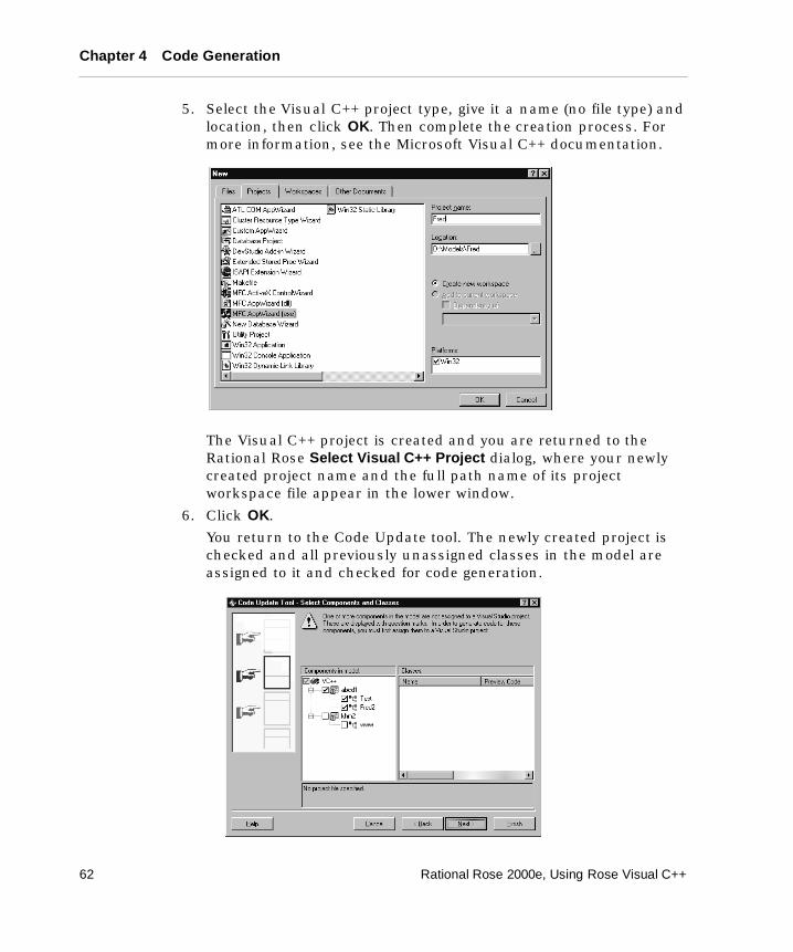
Chapter 4 Code Generation
5. Select the Visual C++ project type, give it a name (no file type) and location, then click OK. Then complete the creation process. For more information, see the Microsoft Visual C++ documentation.
The Visual C++ project is created and you are returned to the Rational Rose Select Visual C++ Project dialog, where your newly created project name and the full path name of its project workspace file appear in the lower window.
6. Click OK.
You return to the Code Update tool. The newly created project is checked and all previously unassigned classes in the model are assigned to it and checked for code generation.
62 Rational Rose 2000e, Using Rose Visual C++
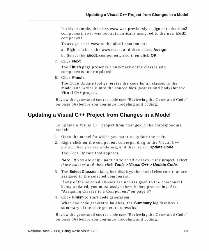
Updating a Visual C++ Project from Changes in a Model
In this example, the class www was previously assigned to the khm2 component, so it was not automatically assigned to the new abcd1 component.
To assign class www to the abcd1 component:
a. Right-click on the www class, and then select Assign.
b. Select the abcd1 component, and then click OK.
7. Click Next.
The Finish page presents a summary of the classes and components to be updated.
8. Click Finish.
The Code Update tool generates the code for all classes in the model and writes it into the source files (header and body) for the Visual C++ project.
Review the generated source code (see “Reviewing the Generated Code” on page 66) before you continue modeling and coding.
Updating a Visual C++ Project from Changes in a Model
To update a Visual C++ project from changes in the corresponding model:
1. Open the model for which you want to update the code.
2. Right-click on the component corresponding to the Visual C++ project that you are updating, and then select Update Code.
The Code Update tool appears.
Note: If you are only updating selected classes in the project, select those classes and then click Tools > Visual C++ > Update Code.
3. The Select Classes dialog box displays the model elements that are assigned to the selected component.
If any of the selected classes are not assigned to the component being updated, you must assign them before proceeding. See “Assigning Classes to a Component” on page 87.
4. Click Finish to start code generation.
When the code generator finishes, the Summary log displays a summary of the code generation results.
Review the generated source code (see “Reviewing the Generated Code” on page 66) before you continue modeling and coding.
Rational Rose 2000e, Using Rose Visual C++ 63
Chapter 4 Code Generation
Previewing Code
The Model Assistant tool allows you to view the code that the Code Update tool generates for a class, operation, attribute, or role. You can view the code before or after code is generated.
Note: The class must be assigned to a component and that component must have an implementation language assigned to it.
To preview a class or class element:
1. Right-click on the class, and then select Model Assistant.
2. Check the box for the class element you want to view.
The code appears in the Preview window.
Controlling Code Generation
This section describes how to generate code for some typical scenarios.
Using Model Properties Other than the Default Set
On the VC++ tab in an element’s specification, you can view the model properties available for a class, class module (component), or operation. You can also view and change their value. To access the tab, select a model element and press F4.
64 Rational Rose 2000e, Using Rose Visual C++
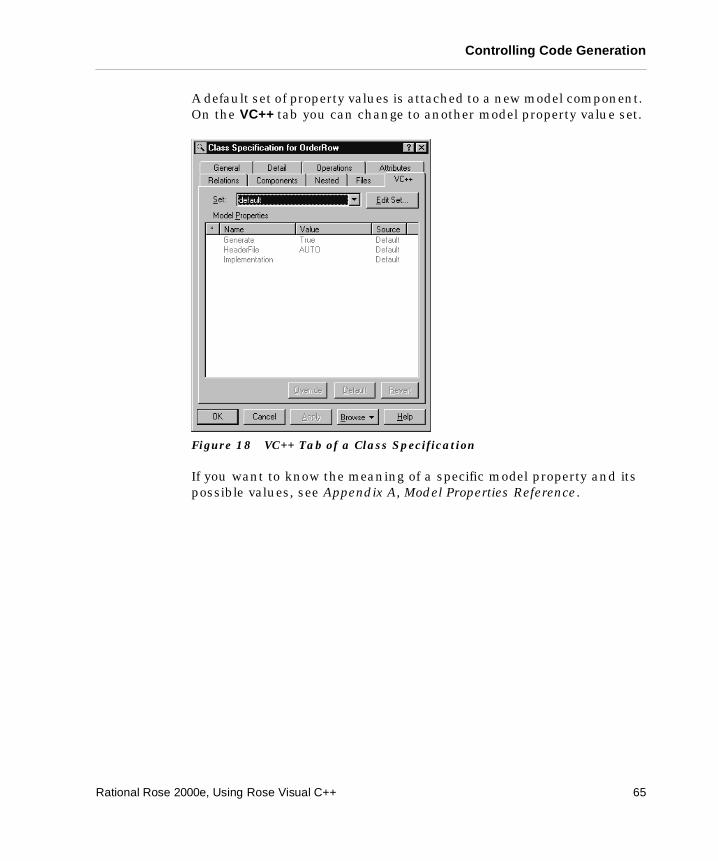
Controlling Code Generation
A default set of property values is attached to a new model component. On the VC++ tab you can change to another model property value set.
Figure 18 VC++ Tab of a Class Specification
If you want to know the meaning of a specific model property and its possible values, see Appendix A, Model Properties Reference.
Rational Rose 2000e, Using Rose Visual C++ 65
Chapter 4 Code Generation
Selecting the Class Stereotype
By default, a new class corresponds to a class in Visual C++. The stereotype of a new class is unspecified (blank), which means Rational Rose Visual C++ produces a class description and definition for it.
To generate code for a modeled class as a struct or enum object, you must change the class stereotype.
To change the class stereotype:
1. Open the specification for the class.
2. On the General tab, click the arrow in the Stereotype field to obtain a list with the available stereotypes.
3. Select the stereotype that corresponds to the implementation type of the class.
Reviewing the Generated Code
This section explains how to review the generated code.
After Code Generation 1. In the Code Update tool Summary dialog box, click the Log tab.
Check the error log for errors and warnings. You can also open the log by selecting Window > Log.
2. Use Microsoft Visual C++ to compile the project. Make certain the generated code contains no syntax errors.
3. Inspect the generated source code in your Microsoft Visual C++ environment by right-clicking on the class, and then selecting Browse Source or Browse Header, as appropriate.
4. Based on your evaluation:
❑ Make the necessary changes to the model and/or to the model properties, and regenerate the code.
❑ Or make the changes directly in the code and update your model.
❑ Or, if necessary, revert to the previous version of the project by clicking Tools > Visual C++ > Restore C++ Source Files.
5. When you are satisfied with the code, use Microsoft Visual C++ to save it.
66 Rational Rose 2000e, Using Rose Visual C++
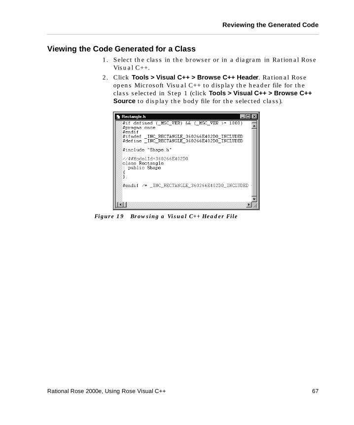
Reviewing the Generated Code
Viewing the Code Generated for a Class 1. Select the class in the browser or in a diagram in Rational Rose
Visual C++.
2. Click Tools > Visual C++ > Browse C++ Header. Rational Rose opens Microsoft Visual C++ to display the header file for the class selected in Step 1 (click Tools > Visual C++ > Browse C++ Source to display the body file for the selected class).
Figure 19 Browsing a Visual C++ Header File
Rational Rose 2000e, Using Rose Visual C++ 67

Chapter 5
Reverse Engineering
This chapter describes how to use Rational Rose Visual C++ to generate or update model elements by reverse engineering a Visual C++ project, class library, or COM object.
Reverse engineering (also called archeology) is the process of extracting design information from a source- or binary-code project, then using that information to generate or update a model representing the project's logical structure.
The reverse engineering process allows you to:
� Create a new model from existing code (archeology).
� Update a model from changes in the code (the reverse engineering portion of round-trip engineering).
� Add code elements from different Visual C++ projects to your model (reusing code elements).
� Add external components to your model.
Once you have the components reverse engineered into your model, you should package and diagram them. See “Packaging and Diagramming Reverse-Engineered Classes” on page 74.
Note: A Visual C++ project corresponds to a component in the component view of a model. Reverse engineering is performed between the project file and the target model.
When reverse engineering source code generated by the Code Update tool from an existing model, code elements that are removed from the project have their corresponding model elements removed from the model. You can choose to confirm or reject these deletions in the Model Update tool’s Synchronize window.
Rational Rose 2000e, Using Rose Visual C++ 69
Chapter 5 Reverse Engineering
Creating a New Model from a Visual C++ Project
Note: Before proceeding with these steps, make certain the project you want to reverse engineer compiles and contains no syntax errors.
To reverse engineer an existing Visual C++ project:
1. Open a new model in Rational Rose.
2. Click Tool > Visual C++ > Update Model from Code (if you see the Welcome screen, click Next).
The Model Update tool appears.
3. In the Project Components window, right-click on Visual C++ and select Add Component.
The Select Visual C++ Project dialog appears.
4. On the Existing tab, browse to the Visual C++ workspace file (.dsw) containing the project to reverse engineer.
5. Select the file, and then click OK.
A dialog indicates a matching workspace file was found.
6. Click OK.
The Model Update tool’s Component window displays the selected Visual C++ project.
7. Click Next to reverse engineer the entire project, or click on the to list the class names in the project. Select the classes to reverse engineer, and then click Next.
The Model Update tool lists the project and classes it will reverse engineer.
8. Click Finish.
The Model Update tool Summary lists the components that were reverse engineered.
9. Click Close.
The newly reverse engineered component is placed in a package with the project name in the Reverse Engineered folder in both the Component view and the Logical view.
10. Assign and diagram your reverse-engineered classes. See “Packaging and Diagramming Reverse-Engineered Classes” on page 74 for more information.
70 Rational Rose 2000e, Using Rose Visual C++
Updating an Existing Model
Updating an Existing Model
Note: Before proceeding with these steps, make certain the project you want to reverse engineer compiles and contains no syntax errors.
To update an existing Visual C++ model:
1. Open the model in Rational Rose.
2. Click Tools > Visual C++ > Update Model from Code (if you see the Welcome screen, click Next).
The Model Update tool appears with the project associated with the model checked for reverse engineering.
3. Click Next to reverse engineer the entire project, or click on the to list the class names in the project. Select the classes to reverse engineer, and then click Next.
The Model Update tool lists the project and classes it is about to reverse engineer.
4. Click Finish.
The Model Update tool Summary lists the components that were reverse engineered.
5. Click Close.
The modeled elements are updated. If you have deleted classes in the code that were previously created by the Code Update tool, the Model Update tool displays a Synchronization window prompting you to confirm the deletion of these classes from the model. See “Synchronizing Model and Code” on page 53.
Adding Code from Other Projects into Your Model
Note: Before proceeding with these steps, make certain the project you want to reverse engineer compiles and contains no syntax errors.
To add code from another project into your Visual C++ model:
1. Open the model in Rational Rose.
2. Click Tools > Visual C++ > Update Model from Code (if you see the Welcome screen, click Next).
The Model Update tool appears and the project associated with the model is checked for reverse engineering.
Rational Rose 2000e, Using Rose Visual C++ 71
Chapter 5 Reverse Engineering
3. In the Project Components window, right-click on Visual C++ and select Add Component.
The Select Visual C++ Project dialog appears.
4. Enter the name of the Visual C++ workspace file (.dsw) containing the project to reverse engineer, or click Browse to find the file. If the workspace contains more than one project, select a project.
5. Click OK.
This adds the new Visual C++ project to the Model Update tool’s Component window.
6. Deselect the existing model project(s).
7. Click Next to reverse engineer the entire project, or click on the to list the class names in the project. Select the classes to reverse engineer, and then click Next.
The Model Update tool lists the project and classes it will reverse engineer.
8. Click Finish.
The Model Update tool Summary lists the components that were reverse engineered.
9. Click Close.
The newly reverse engineered component is placed in a package with the project name under the Reverse Engineered folder in both the Component view and the Logical view.
10. Assign and diagram the reverse-engineered classes. See “Packaging and Diagramming Reverse-Engineered Classes” on page 74 for more information.
Adding External Components to a Model
External components are classes that are not implemented in your application. Instead, they are referenced or are subclassed by model classes and by code implemented in your application (for example, Microsoft Foundation Classes [MFC] or COM objects).
Because they are not implemented in your application’s code, only their interface and internal documentation are reverse engineered. This limited form of reverse engineering is called importing.
72 Rational Rose 2000e, Using Rose Visual C++
Adding External Components to a Model
Importing MFC Classes
To access the Microsoft Foundation Class library from your model, you simply import it: Click Tools > Visual C++ > Quick Import MFC 6.0.
This adds a logical package named MFC to your model, represented by an MFC folder in the Logical view and an MFC component in the Component view. This package contains the complete interface set for all public MFC classes and their internal documentation, if any.
Imported MFC classes have their Generate flag set to false. You only want to reference or subclass these, not generate code for them.
Importing COM Objects
To access COM objects from your model, simply drag and drop the COM object file (.dll, .exe, .ocx, or .tlb) from the Windows Explorer into an open component diagram, a component package, or a logical package in the browser, then click Quick Import or Full Import (as appropriate):
� If the drop target is a component package or one of its diagrams, the new component belongs to that package. Otherwise, the new component is added to the top-level of the Component view and to the main component diagram.
� A logical package with the same name as the new component is created in the Logical view. The new logical package contains the interface elements provided by the corresponding software module. The interface of the new component can now be used by the classes in the model.
� If the drop target is a logical package or one of its diagrams, the logical package for the new component is added to that package.
Two conditions must be met before you can drag-and-drop a COM object into your model:
� The TypeLibImporter add-in must be loaded and activated.
� The selected COM object file must either be a properly registered TypeLib (.tlb) or must contain a TypeLib.
If both of these conditions are not met, the drop into the model is ignored.
Rational Rose 2000e, Using Rose Visual C++ 73
Chapter 5 Reverse Engineering
Note: This process should be restricted to components that are external to the model, or that will be subclassed in the model. External classes should have their Generate flag set to false.
Packaging and Diagramming Reverse-Engineered Classes
When Rational Rose reverse engineers or imports code information, it assigns the resulting model data to a package (with the same name as the project) under the Reverse Engineered package, or to an MFC package, as appropriate. You are responsible for diagramming these components or adding them to other packages.
Diagramming Reverse-Engineered Projects
Diagramming a model is a very subjective process. For this reason, the reverse engineering process generates model data only. It does not generate model diagrams.
You can add classes to a diagram in either of two ways:
� Drag-and-drop classes from the browser to an open diagram.
� Add one or more classes, by name, to the active diagram using the Add Classes dialog box (click Query > Add Classes).
Arrange the diagrammed components to illustrate the architecture of the system. Avoid crossed association lines by moving the classes in the diagram. You can click Edit > Diagram Object Properties to control the level of class details in a diagram.
Dropping Classes into a Diagram
To add a class to a diagram, open the diagram. Then simply drag and drop the individual classes from the browser into the diagram.
The Add Classes Dialog Box
You can use the Add Classes dialog box to move classes from a package to the active diagram:
1. Open the Class diagram where you want to add the classes. Make certain it is the active diagram.
2. Click Query > Add Classes.
74 Rational Rose 2000e, Using Rose Visual C++
Packaging and Diagramming Reverse-Engineered Classes
3. In the Package list, select the package that currently holds your classes.
4. From the Classes window, select the classes you want to move, and transfer them to the Selected Classes window using the arrow button.
5. Click OK.
The selected classes are added to the active diagram.
Arrange the added classes to best illustrate the architecture of the system.
Adding Reverse-Engineered Classes to Packages
While you can leave your new classes in their reverse-engineered project package, you can also move or copy them to other packages in your system. There are several ways to do this:
� Drag-and-drop the class from the Reverse Engineered package to another package.
� Open a class diagram that contains the destination package, then drag-and-drop the class from the Reverse Engineered package to another package.
� Create a new class in your package diagram with the same name as the reverse-engineered one, and then select this new class. Click Edit > Relocate to move the class.
� Cut or Copy, then Paste the class from the Reverse Engineered package to another package.
Rational Rose 2000e, Using Rose Visual C++ 75

Appendix A
Model Properties Reference
This appendix provides a reference to the Rational Rose Visual C++ model properties. Controls on the user interface set most of these properties, so values should not be set on the VC++ tab of the Rational Rose Options dialog (Tools > Options).
These model properties, along with the information contained in a model element's specification, control the code generation for that element. The Visual C++ model properties are grouped as follows:
� Attribute Properties
� Class Properties
� Component Properties
� Operation Properties
� COM Properties
Model Properties for Attributes
Rational Rose Visual C++ controls almost all attribute model properties internally, based on settings on the Attribute Specification. The one exception is the Generate property, which determines whether to generate code for the attribute. Default is True (to generate code).
Model Properties for Classes
Rational Rose Visual C++ controls all class model properties internally. Do not set class model properties on the VC++ tab of the Rational Rose Options dialog (Tools > Options).
Rational Rose 2000e, Using Rose Visual C++ 77
Appendix A Model Properties Reference
The Generate property, which specifies whether Rational Rose Visual C++ creates code for the class, is set using the Generate Code check box on the Class tab of the Model Assistant (right-click on the class and click Model Assistant).
Note: If an existing model uses the HeaderFile property, replace it. Specify header file names on the External Map or Internal Map tabs, as appropriate, on the Component Properties dialog (right-click on the class' component and click Properties).
Model Properties for Components
Rational Rose Visual C++ controls all component model properties internally. They are set on the Component Properties dialog (right-click on a component and click Properties).
Do not set component model properties (Module Specifications) on the Visual C++ tab of the Rational Rose Options dialog (Tools > Options).
Note: The Rational Rose Options dialog (accessed from the Tools menu) refers to these properties as Module Specifications.
Model Properties for Operations
Rational Rose Visual C++ controls almost all attribute model properties internally. The one exception is the Generate property. Do not set other operation model properties on the VC++ tab of the Rational Rose Options dialog (Tools > Options).
The Generate property sets whether code is generated for the operation. Values are True or False.
The DefaultBody property is set by Rational Rose Data Access (if installed) and should not be set by the user.
The Inline property is set by the Inline check box on the Operation tab of the Model Assistant (right-click on the class and click Model Assistant).
For example, if Inline is checked, the code generator writes to customer.h:
Class customer { public: inline get_name()
78 Rational Rose 2000e, Using Rose Visual C++
COM Model Properties
...}inline customer::get_name(){ return custName; }
Extending the example to Inline not checked, the code generator writes to customer.h and to customer.cpp:
In customer.h
Class customer { public: get_name(); ...}
In customer.cpp
customer::get_name() { return custName; }
COM Model Properties
COM model properties only apply only to classes with the stereotype <<interface>>. These properties capture the IDL attributes for COM classes, methods, and method arguments.
COM model properties are documented in the Rational Rose online Help for the TypeLib Importer. The “COM Model Properties — Quick Reference” topic is a map to all of the COM properties.
Rational Rose 2000e, Using Rose Visual C++ 79

Appendix B
Rational Rose Visual C++ Tools
The Rational Rose Visual C++ add-in provides tools and option settings that facilitate a quick and easy interface between a Rational Rose model and Visual C++.
� The Code Update tool
� The Component Assignment tool
� The Model Assistant tool
� The Model Update tool
� The Visual C++ Options window
� A VC++ tab on the Rational Rose Options window
The Code Update Tool
The Code Update tool automates Visual C++ source code generation from the information contained in a Rational Rose model. The Code Update tool generates code from the components in your model into their corresponding Visual C++ projects. Use the Code Update tool to:
� Generate and update several projects of different implementation languages at the same time.
� Access the Model Assistant tool to further specify the mapping between the classes in the model and the code.
� Keep the model and Visual C++ projects synchronized, as the Code Update tool detects any project items that may have been added, renamed, or deleted from the model.
� Access the Component Assignment tool to assign unassigned classes.
Rational Rose 2000e, Using Rose Visual C++ 81
Appendix B Rational Rose Visual C++ Tools
Using the Code Update Tool
There are two ways to start the Code Update tool:
� Click Tools > Visual C++ > Update Code.
� Right-click on a component or class in the browser or in a diagram, and then click Update Code.
Note: If the selected class is not assigned to a component, or if the component is not assigned to a language, the Update Code selection is not available.
The following Code Update tool pages lead you through the process of updating a Visual C++ project from changes in a model:
� Welcome Page
� Select Components and Classes Page
Welcome Page
The Welcome page provides general information about the tool. You can turn this page off by checking the Don’t show this page in the future option.
Select Components and Classes Page
The Select Components and Classes page changes, depending on whether all of the displayed elements are properly assigned.
82 Rational Rose 2000e, Using Rose Visual C++
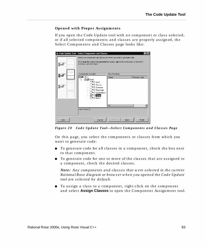
The Code Update Tool
Opened with Proper Assignments
If you open the Code Update tool with no component or class selected, or if all selected components and classes are properly assigned, the Select Components and Classes page looks like:
Figure 20 Code Update Tool—Select Components and Classes Page
On this page, you select the components or classes from which you want to generate code:
� To generate code for all classes in a component, check the box next to that component.
� To generate code for one or more of the classes that are assigned to a component, check the desired classes.
Note: Any components and classes that were selected in the current Rational Rose diagram or browser when you opened the Code Update tool are selected by default.
� To assign a class to a component, right-click on the component and select Assign Classes to open the Component Assignment tool.
Rational Rose 2000e, Using Rose Visual C++ 83
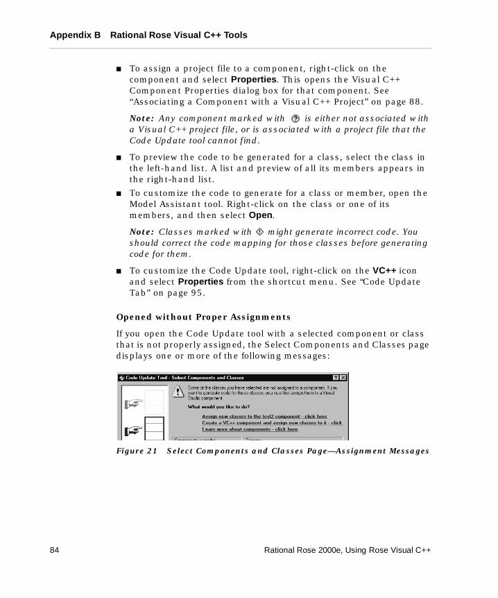
Appendix B Rational Rose Visual C++ Tools
� To assign a project file to a component, right-click on the component and select Properties. This opens the Visual C++ Component Properties dialog box for that component. See “Associating a Component with a Visual C++ Project” on page 88.
Note: Any component marked with is either not associated with a Visual C++ project file, or is associated with a project file that the Code Update tool cannot find.
� To preview the code to be generated for a class, select the class in the left-hand list. A list and preview of all its members appears in the right-hand list.
� To customize the code to generate for a class or member, open the Model Assistant tool. Right-click on the class or one of its members, and then select Open.
Note: Classes marked with might generate incorrect code. You should correct the code mapping for those classes before generating code for them.
� To customize the Code Update tool, right-click on the VC++ icon and select Properties from the shortcut menu. See “Code Update Tab” on page 95.
Opened without Proper Assignments
If you open the Code Update tool with a selected component or class that is not properly assigned, the Select Components and Classes page displays one or more of the following messages:
Figure 21 Select Components and Classes Page—Assignment Messages
84 Rational Rose 2000e, Using Rose Visual C++
The Code Update Tool
� Assign new classes to the <name> component – clicking this line takes you:
❑ To the Component Assignment tool, where you assign classes to the indicated component,
❑ Then back to the Code Update tool to complete your code generation.
Note: <name> is displayed because there is only one component in this model. If there is a choice, <name> does not appear.
� Create a VC++ component and assign classes to it – clicking this line takes you:
❑ To the Visual C++ IDE New Projects wizard, where you create a new Visual C++ project and automatically create a new assigned component of the same name,
❑ Then to the Component Assignment tool, where you assign classes to your new component,
❑ Then back to the Code Update tool to complete your code generation.
� Learn more about components – clicking this line presents Help topics about components and the component assignment process.
Finish Page
This page displays a summary of the code to be generated. Click Finish if you are satisfied, or click <Back if you want to change something.
Progress Page
This page displays the progress of the code generation.
Synchronize Page
This page appears when the Code Update tool detects code elements in the Visual C++ project that have no corresponding elements in the model. Here you can confirm the deletion of each such code element. See “Synchronizing Model and Code” on page 53.
Rational Rose 2000e, Using Rose Visual C++ 85
Appendix B Rational Rose Visual C++ Tools
Summary Page
This page displays a summary of the code generation results. Right-click anywhere in the Log window for a shortcut menu, where you can choose whether to display warnings and errors in color and to use timestamps.
The information on the Log tab is also available in the Rational Rose Log window after exiting the Code Update tool (click Window > Log).
The Component Assignment Tool
The Component Assignment tool provides a quick and easy way to:
� Create new components
� Assign classes to components
� Associate a component with a Visual C++ project
� Assure that the components you create contain all the information needed to generate Visual C++ code
Using the Component Assignment Tool
There are two ways to open the Component Assignment tool:
� Click Tools > Visual C++ > Component Assignment Tool.
� Right-click on an existing component in the Code Update tool, and then click Assign classes.
The Component Assignment tool appears.
86 Rational Rose 2000e, Using Rose Visual C++
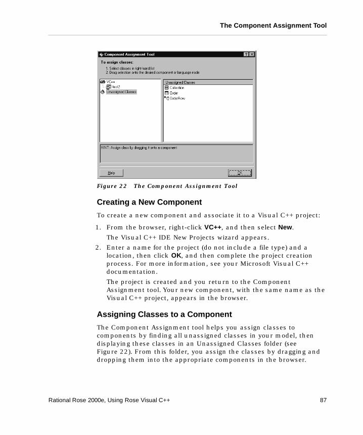
The Component Assignment Tool
Figure 22 The Component Assignment Tool
Creating a New Component
To create a new component and associate it to a Visual C++ project:
1. From the browser, right-click VC++, and then select New.
The Visual C++ IDE New Projects wizard appears.
2. Enter a name for the project (do not include a file type) and a location, then click OK, and then complete the project creation process. For more information, see your Microsoft Visual C++ documentation.
The project is created and you return to the Component Assignment tool. Your new component, with the same name as the Visual C++ project, appears in the browser.
Assigning Classes to a Component
The Component Assignment tool helps you assign classes to components by finding all unassigned classes in your model, then displaying these classes in an Unassigned Classes folder (see Figure 22). From this folder, you assign the classes by dragging and dropping them into the appropriate components in the browser.
Rational Rose 2000e, Using Rose Visual C++ 87
Appendix B Rational Rose Visual C++ Tools
Associating a Component with a Visual C++ Project
To associate an existing component with a Visual C++ project:
1. Right-click on the component, and then select Properties.
The Visual C++ Component Properties window appears.
2. In the Project File window, enter the full path and file name for the Visual C++ project file (.dsp).
Optionally, you can enter the full path and file name for the Visual C++ workspace file (.dsw) in the Workspace File window.
You can also use the browse buttons to find and enter your path and file names.
3. Make certain the Generate Code box is checked, or no code will be generated for this project or for the classes in it.
4. If you want to enter comments in the generated code about this project, enter them in the Documentation window.
5. Click OK.
The Model Assistant Tool
The Model Assistant tool helps you correctly and accurately define common and custom Visual C++ programming and modeling constructs for modeled elements. Use the Model Assistant to:
� Create constants, Declare statements, Event handlers, Enum and Type declarations, attributes, and operations.
� Create Get and Set procedures for class attributes and association roles.
� Define and create a user-defined collection class for the class.
� Preview the code to be generated for the class and each of its members.
� Specify implementation details about the class and its members.
� Apply code templates for code body generation.
88 Rational Rose 2000e, Using Rose Visual C++
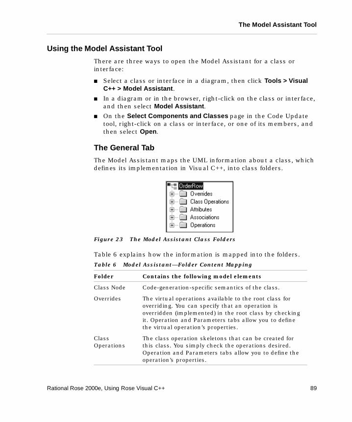
The Model Assistant Tool
Using the Model Assistant Tool
There are three ways to open the Model Assistant for a class or interface:
� Select a class or interface in a diagram, then click Tools > Visual C++ > Model Assistant.
� In a diagram or in the browser, right-click on the class or interface, and then select Model Assistant.
� On the Select Components and Classes page in the Code Update tool, right-click on a class or interface, or one of its members, and then select Open.
The General Tab
The Model Assistant maps the UML information about a class, which defines its implementation in Visual C++, into class folders.
Figure 23 The Model Assistant Class Folders
Table 6 explains how the information is mapped into the folders.
Table 6 Model Assistant—Folder Content Mapping
Folder Contains the following model elements
Class Node Code-generation-specific semantics of the class.
Overrides The virtual operations available to the root class for overriding. You can specify that an operation is overridden (implemented) in the root class by checking it. Operation and Parameters tabs allow you to define the virtual operation’s properties.
Class Operations
The class operation skeletons that can be created for this class. You simply check the operations desired. Operation and Parameters tabs allow you to define the operation’s properties.
Rational Rose 2000e, Using Rose Visual C++ 89
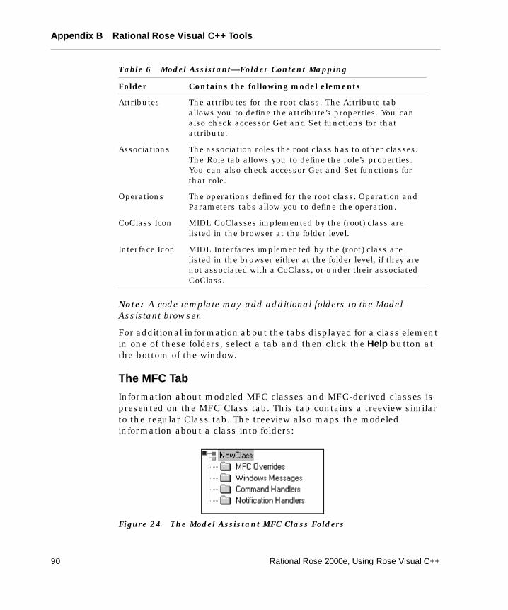
Appendix B Rational Rose Visual C++ Tools
Note: A code template may add additional folders to the Model Assistant browser.
For additional information about the tabs displayed for a class element in one of these folders, select a tab and then click the Help button at the bottom of the window.
The MFC Tab
Information about modeled MFC classes and MFC-derived classes is presented on the MFC Class tab. This tab contains a treeview similar to the regular Class tab. The treeview also maps the modeled information about a class into folders:
Figure 24 The Model Assistant MFC Class Folders
Attributes The attributes for the root class. The Attribute tab allows you to define the attribute’s properties. You can also check accessor Get and Set functions for that attribute.
Associations The association roles the root class has to other classes. The Role tab allows you to define the role’s properties. You can also check accessor Get and Set functions for that role.
Operations The operations defined for the root class. Operation and Parameters tabs allow you to define the operation.
CoClass Icon MIDL CoClasses implemented by the (root) class are listed in the browser at the folder level.
Interface Icon MIDL Interfaces implemented by the (root) class are listed in the browser either at the folder level, if they are not associated with a CoClass, or under their associated CoClass.
Table 6 Model Assistant—Folder Content Mapping
Folder Contains the following model elements
90 Rational Rose 2000e, Using Rose Visual C++
The Model Assistant Tool
Table 7 explains how the information is mapped into the folders.
For additional information about the tabs displayed for a class element in one of these folders, select a tab and then click the Help button at the bottom of the window.
Search Box
You use the Search box to find elements within the class by entering a search string, and to navigate to other classes within the model. Use the following shortcuts to navigate the Search box.
� CTRL-F (find), or the mouse cursor, moves the insertion point into the Search box.
Enter a search string, then press ENTER to select the first occurrence of the string in the MFC Treeview window, or use the look-up and look-down buttons to navigate to the search-string matches.
Table 7 Model Assistant—Folder Content Mapping
Folder Contains the following model elements
Class Node Code-generation-specific semantics of the class. An MFC tab allows you to modify classes that derive from an MFC class.
MFC Overrides The virtual operations available to the root class for overriding. This applies only to MFC-derived classes. You can specify that an operation is overridden (implemented) in the root class by checking it. Operation and Parameters tabs allow you to define the virtual operation’s properties.
Windows Messages
Lists the handlers for all the Windows messages the class can receive. Checking an operation allows you to modify its aspects on its Message Handler tab.
Command Handlers
List all the command handlers defined for the base class. Selecting an operation allows you to modify its aspects on its Command Handler tab.
Notification Handlers
Lists all the notification handlers defined for the base class. Selecting an operation allows you to modify its aspects on its Notification Handler tab.
Rational Rose 2000e, Using Rose Visual C++ 91
Appendix B Rational Rose Visual C++ Tools
� From the Search box, CTRL-ENTER loads all class names in the model into the Search box drop-down menu. Selecting a class name from the menu loads that class into the Model Assistant and nulls the Search box.
Information Tabs
Selecting a model element presents one or more tabs containing information about that model element. The nature of the element, and how it is modeled, determines what information on the tab you can change. To learn more about the information for a model element, select a tab and then click the Help button at the bottom of the window.
The Model Update Tool
The Model Update tool automates creating and updating a Rational Rose model from a Visual C++ source code project. Use the Model Update tool to:
� Reverse engineer a Visual C++ project to create a new model based on its code
� Update an existing model with changes made to the Visual C++ code
� Update several components of different implementation languages at the same time
� Keep the model and source code projects synchronized—the Model Update tool detects any model elements that may have been deleted from the code
� Add new components to the model
Using the Model Update Tool
There are two ways to start the Model Update tool:
� Click Tools > Visual C++ > Update Model from Code.
� Right-click on a component, and then select Update Model from Code.
92 Rational Rose 2000e, Using Rose Visual C++
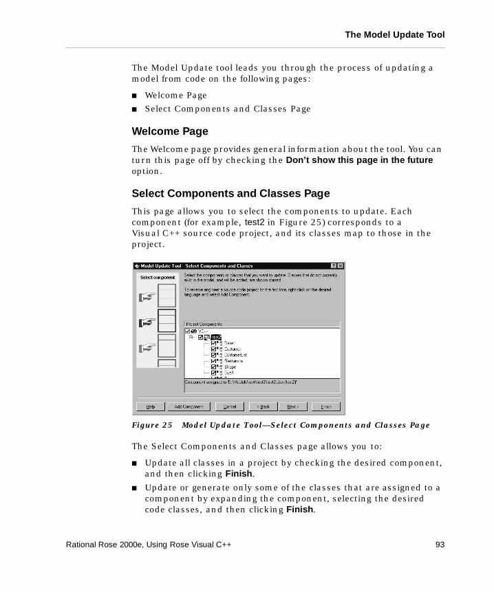
The Model Update Tool
The Model Update tool leads you through the process of updating a model from code on the following pages:
� Welcome Page
� Select Components and Classes Page
Welcome Page
The Welcome page provides general information about the tool. You can turn this page off by checking the Don’t show this page in the future option.
Select Components and Classes Page
This page allows you to select the components to update. Each component (for example, test2 in Figure 25) corresponds to a Visual C++ source code project, and its classes map to those in the project.
Figure 25 Model Update Tool—Select Components and Classes Page
The Select Components and Classes page allows you to:
� Update all classes in a project by checking the desired component, and then clicking Finish.
� Update or generate only some of the classes that are assigned to a component by expanding the component, selecting the desired code classes, and then clicking Finish.
Rational Rose 2000e, Using Rose Visual C++ 93
Appendix B Rational Rose Visual C++ Tools
Note: Classes marked with a star do not exist in the model. When selecting such a class, the class will be created in the model. Also, you can select several components. Each selected component is then updated from the changes of its associated project.
� Assign an existing component with a project file by right-clicking on the component, and then clicking Properties. This brings up the component’s Visual C++ Component Properties dialog box.
� Customize general aspects of the Model Update tool by right-clicking on VC++, and then clicking Properties. See “Model Update Tab” on page 96.
To reverse engineer a project, the project must be represented in the model by a component. If your project has no component:
1. Right-click on VC++, and then select Add Component.
The Visual C++ IDE New Projects wizard appears.
2. Enter a name for the project (do not include a file type) and a location, then click OK, and then complete the project creation process. For more information, see your Microsoft Visual C++ documentation.
The project is created and you return to the Model Update tool. Your new component, with the same name as the Visual C++ project, appears in the browser.
Finish Page
This page presents a summary of what will be updated in the model. Click Finish if you are satisfied, or <Back if you want to change something.
Progress Page
This page displays the progress of the model update process.
Synchronize Page
This page appears if the Model Update tool detects any model elements that have no corresponding elements in the Visual C++ project code. Here you can confirm the deletion of each such model element. See “Synchronizing Model and Code” on page 53.
94 Rational Rose 2000e, Using Rose Visual C++
The Visual C++ Options Window
Summary Page
This page displays a summary of the code generation results. Right-click anywhere in the Log window for a shortcut menu, where you can choose whether to display warnings and errors in color and to use timestamps.
The information on the Log tab is also available in the Rational Rose Log window after exiting the Code Update tool (click Window > Log).
The Visual C++ Options Window
The Visual C++ Options window controls how the Rational Rose Visual C++ tools operate. The window is divided into five tabs:
� Code Update
� Model Update
� Containers
� Class Operations
� Accessors
Items on a list on any of these tabs can be added, deleted, or renamed, by right-clicking and using the shortcut menu, or the names can be changed by pressing F2.
Code Update Tab
The Code Update tab contains five switches that determine how the Code Update tool operates:
� Generate Model IDs – when set, Model IDs are generated for classes and member functions. When unset, Model IDs are not generated.
� Generate Documentation – when set, code comments are generated for information contained in the Documentation field for a model element. When unset, code comments are not generated.
� Generate #include Statements – when set, #include statements are generated for a header file, as discussed in “Code Generated for Classes” on page 18. When unset, #include statements are not generated.
� Apply Pattern on Code Generation – when set, the prototypes that are checked on the Class Operations and Accessors tabs are used when generating code for a class.
Rational Rose 2000e, Using Rose Visual C++ 95
Appendix B Rational Rose Visual C++ Tools
Note: The information on the Class Operations and Accessors tabs is used the first time code is generated for a class, and to preview code in the Model Assistant tool.
Note: The following Debug switch is only available if the Apply Pattern switch is checked.
❑ Generate Debug Operations for MFC Classes – generates DUMP and AssertValid operations for classes derived from MFC class CObject.
Model Update Tab
The Model Update tab contains one switch, an attribute-type list, and Add and Delete buttons, which determine how the Model Update tool operates.
� Reverse Engineer Documentation – when set, code comments found in the reverse-engineered source code are written to the Documentation field of the appropriate model elements. When unset, code comments are ignored.
� Attribute Types – lists the Visual C++ types that indicate a data member is an attribute and not a role. This list is used by the Model Update tool during reverse engineering.
� The Add and Delete buttons allow you to add or delete types from the list.
Containers Tab
The Containers tab lists the Visual C++ container classes that are recognized for reverse engineering by the Model Update tool. The default population for this list are the MFC container classes. User-defined container classes may be added to this list.
The Add and Delete buttons allow you to add or delete container classes from the list.
Container class definitions may contain the $TYPE variable, which expands to any Visual C++ type.
96 Rational Rose 2000e, Using Rose Visual C++
The Visual C++ Options Window
Class Operations Tab
The Class Operations tab lists the class operations that can be generated for each class. Any operation that is checked is generated, but only if the Apply Pattern on Code Generation switch (on the Code Update tab) is also checked. By default, two operations are checked for code generation:
� $NAME() – generates the default constructor
� <<virtual>> ~$NAME() – generates a virtual destructor for the class
Note: The information on this tab is used the first time code is generated for a class, and to preview code in the Model Assistant tool.
Accessors Tab
The Accessors tab controls whether accessor Get and Set code is generated for a modeled role or attribute. The default is not to generate Get and Set accessors.
Four accessor prototypes are defined for each Get and Set accessor. The prototype used for code generation depends on the type of the role or attribute being modeled:
� int – an intrinsic or fundamental data type. For example, integer, double, char, etc.
� usr – a user-defined type
� ptr – a pointer
� ref – a reference
Accessor prototypes may contain the following variables:
� $NAME – expands to the attribute or role name as entered in the model.
� $BASICNAME – expands to the attribute or role name as entered in the model, unless the model name begins with an m_ prefix. If so, the prefix is stripped to the first uppercase letter. For example, if $BASICNAME represents a modeled attribute of m_strClassName, the name generated for the class would be ClassName.
� $TYPE – expands to the attribute or role type.
Accessor definitions can be changed by right-clicking or pressing F2, but they cannot be added or deleted.
Rational Rose 2000e, Using Rose Visual C++ 97
Appendix B Rational Rose Visual C++ Tools
Note: The information on this tab is used the first time code is generated for a class, and to preview code in the Model Assistant tool.
The Options VC++ Tab
The VC++ tab on the Rational Rose Options window lists the public model properties, and their current values, available for current model elements. The property values on this page are the default values for all applicable elements in the model. Specific values for individual model elements are listed on the element’s Specification. Model properties are listed for:
� Attributes
� Classes
� Components
� Generalizations
� Operations
� Packages
� Projects (note that these properties apply to the Rational Rose model, not to the Visual C++ project)
� Roles
For descriptions of the individual model properties, right-click on the property name to display the online Help.
98 Rational Rose 2000e, Using Rose Visual C++
Index
Symbols#include, and model classes 18
Aabstract operation stereotype 26access
class 18operation 25private 18protected 18public 18
accessor functions 28accessor get 28accessor set 28aggregation relationships 32, 48applying code templates to a class 21arguments 25assigning
classes to a component 87component to a language 60component to a project 88
association relationships 29ATL
support 2, 4, 42attributes
and code comments 28documentation field 28mapping to Visual C++ 28
Rational Rose 2000e, Using Rose Visual C++
previewing code for 64
BBooch notation xvbrowse code 67business services 48, 57
Ccardinality 35class
access 18diagrams 17scope, see access 18stereotypes 18, 20, 66utilities 23
class declarations, and model classes 18class model properties
HeaderFile 78classes
and #include 18and class declarations 18and code comments 18and data members 18and member function declarations 18assigning to a component 87mapping to Visual C++ 18previewing code for 64
client/server design 48
99
Index
code comments 9and attributes 28and classes 18and operations 25mapping to model 47
code generation 3, 7, 59and model IDs 18Code Update Tool 81controlling 64from a model 61of aggregation relationships 32of association relationships 29of attributes 64of cardinalities 35of class utilities 23of classes 18of collection classes 35of components 38of dependency relationships 33of deployment view 40of documentation field 9of generalization relationships 33of inherits relationships 33of logical view 17of multiplicities 35of navigability adornments 34of operation documentation field 25of operation parameters 27of operations 24, 25, 64of packages 38of roles 29, 64of uses relationships 33previewing classes 64selecting implementation type 66
code template files 22code templates 8
applying to a class 21creating 22modifying 22removing from a class 21
Code Update tool 3defined 81
100
see also code generationcollection classes 35COM
objects 43support 2, 4, 42
COM CoClasses 23COM Objects 8comments in source code 9component 38
generating code for 38mapping to Visual C++ 38stereotypes 40
component assignment 60, 87, 88Component Assignment tool 2
defined 86component model properties 78component view 57conceptual design 5const operation stereotype 27contents of a model 56creating a new model 56creating a new model from code 70, 71creating code templates 22
Ddata link library 40, 73data member mapping 28data members
and model classes 18data services 48, 57dependency relationship 33deployment view 57deployment view mapping 40DLL 40, 73DLL project 40, 41documentation field
and attributes 28for classes 18for model elements 9for operations 25
Rational Rose 2000e, Using Rose Visual C++
Index
EEXE 40, 73EXE project 40, 41external components
and packages 38referencing 72
Ffriend operation stereotype 27
Ggeneralization relationships 33generate source code 61generating code
Code Update tool 81
HHeaderFile class property 78
IIDL 22inheritance 33inherits relationships 33interface classes 22iterative lifecycle 5
Llogical design 6logical packages 38logical view 57logical view mapping 17
Mmapping
accessor get/set to Visual C++ 28
Rational Rose 2000e, Using Rose Visual C++
aggregations to Visual C++ 32, 48applying code templates to a class 21associations to Visual C++ 29attributes to Visual C++ 28class utilities to Visual C++ 23classes to Visual C++ 18, 41code templates to Visual C++ 21components to Visual C++ 38dependencies to Visual C++ 33generalizations to Visual C++ 33MFC classes to model classes 41operations to Visual C++ 24removing code templates from a class
21member function declarations
and model classes 18member variable, see data membermethod, see operationMFC
classes 2, 4, 41mapping to model classes 41
Microsoft IDL 22Model Assistant tool 2
and accessor functions 28and code generation 20and collection classes 35and get/set functions 28and previewing code 64defined 88
model ID in the code 18model properties 8, 64, 77
for attributes 77for classes 77for components 78for operations 78HeaderFile 78
Model Update tool 3defined 92see also reverse engineering
modifying code templates 22multiplicity 35
101
Index
Nname of an operation 25navigability adornment 34
Oobject modeling 7OCX 73OMT notation xvoperation
access 25accessor functions 28and code comments 25code generated for 25documentation field 25mapping to Visual C++ 24names 25parameter passing 27parameters 25previewing code for 64scope, see access 25semantics 25stereotypes 25
operation model properties 78operation stereotypes 26
abstract 26const 27friend 27static 27virtual 27
Ppackages 38
and external components 38parameter passing 27parameterized classes 23parameters, operation 25physical design 6previewing code
for attributes 64
102
for classes 64for operations 64for roles 64
private access 18project 41Project Selection dialog 61, 62, 70, 72project types 40protected access 18public access 18
Rreferencing external components 72removing code templates from a class 21reverse engineering 3, 69
adding external components 72code-to-model mappings 40creating new model 70, 71data members 41of COM objects 43of comments 47of const declarations 41of DLL, EXE, OCX, TLB files 73of MFC objects 41of projects 41of Visual C++ projects 41
reverse engineering mapping rules 40roles 29
previewing code for 64round-trip engineering 3
defined 49starting with code 55the process 51
Sscenario analysis 5Semantics tab 25source code 66
mapping of comments 47source code generation 54static operation stereotype 27
Rational Rose 2000e, Using Rose Visual C++
Index
stereotypes 8, 18of classes 20, 66of components 40of operations 26
synchronization 53
TThree-Tiered architecture 48Three-Tiered model 48type library 73
UUML xv, 17unified modeling language, see UMLuse-case view 58user services 48, 57uses relationships 33
Vviewing code
for attributes 64for classes 64for operations 64for roles 64
virtual operation stereotype 27Visual C++ mappings 17Visual C++ project
generating 40reverse engineering 41
Visual C++ to model mappings 40
Rational Rose 2000e, Using Rose Visual C++
103