Embed Size (px)
Citation preview

Rational Synthesis of Nanomagnets and Magnetic Nanocomposites
for Permanent Magnet Applications
By
Bo Shen
B.Sc., Nankai University, 2013
M.A., Brown University, 2015
A Dissertation Submitted in Partial Fulfillment of the
Requirements for the Degree of Doctor of Philosophy
in the Department of Chemistry at Brown University
Providence, Rhode Island
May 2019

© Copyright 2019
by
Bo Shen

iii
This dissertation by Bo Shen is accepted in its present form
by the Department of Chemistry as satisfying the dissertation requirement
for the degree of Doctor of Philosophy.
Date ______________ _____________________
Shouheng Sun, Advisor
Recommended to the Graduate Council by
Date ______________ _____________________
Eunsuk Kim, Reader
Date ______________ _____________________
Lai-Sheng Wang, Reader
Approved by the Graduate Council
Date ______________ _____________________
Andrew G. Campbell, Dean of the Graduate School

iv
Curriculum Vitae
Bo Shen was born on June 15, 1990, in Zhangjiakou, Hebei, China. He grew up in
Tianjin and studied in Nankai University (Tianjin, China) from 2009 to 2013,
graduating with obtaining B.Sc. degree in Chemistry. In 2013, he was admitted with a
fellowship in the graduate program of the Department of Chemistry at Brown
University, pursuing the degree of Doctor of Philosophy in Chemistry. During this time,
he worked as research and teaching assistants. Since January 2014, he has been focusing
on the rational synthesis of nanomagnets and magnetic nanocomposites for permanent
magnet applications under the supervision of Professor Shouheng Sun. He has 12
papers published thus far in peer-reviewed journals and 1 patent in pending.

v
Publications
[13] Bo Shen, Chao Yu, Scott K. McCall, Zhouyang Yin and Shouheng Sun*, “A
general way to Synthesize Sm based Nanomagnets” 2018, in preparation.
[12] Bo Shen, Chao Yu, Dong Su, Zhouyang Yin, Junrui Li, Zheng Xi and Shouheng
Sun*, “A novel Approach to Anisotropic SmCo5 Nanomagnets” Nanoscale, 2018, 10,
8735-8740.
[11] Bo Shen, Adriana Mendoza-Garcia, Sarah E. Baker, Scott K. McCall, Chao Yu,
Liheng Wu and Shouheng Sun*, “Stabilizing Fe Nanoparticles in the SmCo5 Matrix”
Nano Lett., 2017, 17, 5695–5698.
[10] Junrui Li, Zheng Xi, Jacob S. Spendelow, Paul N. Duchesne, Dong Su, Qing Li,
Chao Yu, Zhouyang Yin, Bo Shen, Yu Seung Kim, Peng Zhang and Shouheng Sun*,
“Ordered Intermetallic Core/Shell FePt/Pt Nanoparticle with Atomic Layers of Pt as
Highly Active and Durable Oxygen Reduction Catalyst Utilized for Fuel Cells” J. Am.
Chem. Soc., 2018, 140, 2926–2932.
[9] Chao Yu, Xuefeng Guo, Mengqi Shen, Bo Shen, Michelle Muzzio, Zhouyang
Yin, Qing Li, Zheng Xi, Junrui Li, Christopher T. Seto* and Shouheng Sun*,
“Maximizing the Catalytic Activity of Nanoparticles through Monolayer Assembly on
Nitrogen-Doped Graphene” Angew. Chem. Int. Ed. 2018, 57, 451-455.
[8] Chao Yu, Xuefeng Guo, Zheng Xi, Michelle Muzzio, Zhouyang Yin, Bo Shen,
Junrui Li, Christopher T. Seto* and Shouheng Sun*, “AgPd Nanoparticles Deposited
on WO2.72 Nanorods as an Efficient Catalyst for One-Pot Conversion of
Nitrophenol/Nitroacetophenone into Benzoxazole/Quinazoline” J. Am. Chem. Soc.

vi
2017, 139, 5712-5715.
[7] Qing Li*, Jiaju Fu, Wenlei Zhu, Zhengzheng Chen, Bo Shen, Liheng Wu, Zheng
Xi, Tanyuan Wang, Gang Lu, Jun-jie Zhu and Shouheng Sun*, “Tuning Sn-Catalysis
for Electrochemical Reduction of CO2 to CO via the Core/Shell Cu/SnO2 Structure”
J. Am. Chem. Soc. 2017, 139, 4290-4293.
[6] Guangming Jiang, Huiyuan Zhu*, Xu Zhang, Bo Shen, Liheng Wu, Sen Zhang,
Gang Lu, Zhongbiao Wu* and Shouheng Sun*, “Core/Shell Face-Centered
Tetragonal FePd/Pd Nanoparticles as an Efficient Non-Pt Catalyst for the Oxygen
Reduction Reaction” ACS Nano, 2015, 9, 11014–11022.
[5] Liheng Wu, Bo Shen, Shouheng Sun*, “Synthesis and Assembly of Barium-
doped Iron Oxide Nanoparticles and Nanomagnets” Nanoscale, 2015,7, 16165-16169
[4] Liheng Wu, Qing Li, Cheng Hao Wu, Huiyuan Zhu, Adriana Mendoza-Garcia, Bo
Shen, Jinghua Guo and Shouheng Sun*, “Stable Cobalt Nanoparticles and Their
Monolayer Array as an Efficient Electrocatalyst for Oxygen Evolution Reaction” J.
Am. Chem. Soc., 2015, 137, 7071–7074
[3] Bo Shen, Peng-Fei Shi, Yin-Ling Hou, Fan-Fan Wan, Dong-Liang Gao and Bin
Zhao*, “Structural diversity and magnetic properties of five copper-organic
frameworks containing one-, two-, and three-types of organic ligands” Dalton Trans.,
2013, 42, 3455-3463.
[2] Yin-Ling Hou, Gang Xiong, Bo Shen, Bin Zhao*, Zhi Chen and Jian-Zhong Cui*,
“Structures, luminescent and magnetic properties of six lanthanide–organic
frameworks: observation of slow magnetic relaxation behavior in the DyIII

vii
compound” Dalton Trans., 2013, 42, 3587-3596.
[1] Peng-Fei Shi, Zhi Chen, Gang Xiong, Bo Shen, Jing-Zhe Sun, Peng Cheng* and
Bin Zhao* “Structures, Luminescence, and Magnetic Properties of Several Three-
Dimensional Lanthanide–Organic Frameworks Comprising 4-Carboxyphenoxy
Acetic Acid” Cryst. Growth Des., 2012, 12, 5203–5210.

viii
Acknowledgements
To be a chemist is my dream. And the dream is becoming more and more realistic
in my PhD career at Brown University. Looking back to the five years, I would like to
thank many wonderful people who has made my Ph.D. study colorful and meaningful.
First of all, my greatest thanks are definitely given to my research advisor, Prof.
Shouheng Sun. Before coming to Brown, I was deeply attracted by his excellent
research in magnetic nanomaterials. In my first semester, I chose his course of
Nanoscale Materials CHEM 1700. His lecture is always vivid and his logic flow is
always scientific, with clear concepts and systematical summary. He opened a new gate
of the amazing nano-world to me. In the second semester, I was lucky enough to join
his lab and started my research career at Brown University. In the past five years, I
learned a lot from not only the scientific method to research but also his noble
personality, like his endless passion to science, his critical thinking and his strict
training on logical conversation for the future career. He is not only my Ph.D. advisor,
but also like a father or friend. He would directly point out my drawbacks on research.
When I felt frustrated, he would warmly encourage me with applauding for my progress.
In these year, I gradually understand what the quality of a Ph.D. should have. I cannot
think of how my Ph.D. career would be without his guidance and support. The time and
experience I worked with him is a great treasure for my future career.
I am also grateful to my committee members, Prof. Eunsuk Kim and Prof. Lai-
Sheng Wang. During these years, they are always helpful to provide me valuable
suggestions and shared their valuable time on my RPD, ORP and defense. Thanks go

ix
to Prof. J. William Suggs, for his encouragement and help of my class during my first
year at Brown. I also appreciate Dr. Li-Qiong Wang, for her great help in my teaching
career and daily life.
I feel lucky enough to have the greatest collaborators and group members. Without
their help, it would be very tough to finish my research. Thank my close cooperators
Dr. Scott McCall, Dr. Sarah Baker and Dr. Alexander Baker in Lawrence Livermore
National Laboratory for magnetic properties measurement. Thank Dr. Dong Su at
Brookhaven National Laboratory for his work on STEM analysis of my samples. My
appreciations also deliver to Dr. Anthony McCormick for his help on SEM and TEM
operation, Dr. Paul Waltz and Dr. Garces Hector for XRD operation in the Department
of Engineering at Brown. Thanks to Prof. Gang Xiao and his student Wenzhe Chen and
Lijuan Qian for magnetic properties measurement in Physics Department, also Dr.
Joseph Orchardo in the Department of Geological Science at Brown for the help with
ICP measurement. Thank to Kenneth Talbot and Randy Goulet for mechanical
instrument making. Thanks go to my excellent group members, Dr. Chao Yu, my best
friend and closest cooperator in magnetic projects and catalysis projects, Dr. Adriana
Mendoza-Garcia and Dr. Liheng Wu for training me nanoparticle synthesis and
magnetic characterization when I was a green-hand. A special acknowledgement goes
to Dr. Qing Li, Dr. Sen Zhang, Dr. Huiyuan Zhu, Dr. Guangming Jiang, Junrui Li,
Zhouyang Yin, Jiaju Fu, Hu Liu for their assistance in experiment and a lot of precious
time we had together. Thanks to my roommate and lab partner Dr. Zheng Xi for the
help not only in research but also in daily life. I also like to thank Dr. Wenlei Zhu, Dr.

x
Hongyi Zhang, Yuyang Li, Michelle Muzzio, Mengqi Shen, Honghong Lin, Kecheng
Wei, Joshua Dunn, and all other Sun group members.
Finally, I would thank my parents for their endless love and support in my life. I
love you!

xi
To my family

xii
Abstract of “Rational Synthesis of Nanomagnets and Magnetic Nanocomposite for
Permanent Magnet Applications” by BO SHEN, Ph. D., Brown University, May 2019.
In the past two decades, the synthesis of magnetic nanoparticles (NPs) has been
intensively explored for both fundamental scientific research and industrial applications.
Different from the bulk sintered or bonded magnet, magnetic NPs show unique
magnetic properties, which permits to adjust their magnetism by systematic nanoscale
engineering. This thesis focuses on the synthesis of permanent nanomagnets, as well as
magnetic hard-soft phase exchange-coupled nanocomposite for their applications in
energy store and convention as permanent magnets.
The traditional bulk permanent magnet with the largest magnetic energy product
is NdFeB. However, the Curie temperature is low and it cannot be used above 200 oC.
SmCo alloy, a class of hard magnets for NdFeB substitution, shows a large coercivity
and high Curie temperature. But the relative low moment limits its usage. To solve the
problem, SmCo need to exchange-coupled with soft magnet like Fe to form
nanocomposite. The traditional way is to mix SmCo and Fe NPs together and anneal it.
This method causes Fe NPs diffusing into SmCo matrix to form SmCoFe alloy,
decreasing their magnetic property. We coated the pre-synthesized Fe NPs with SiO2
and assembled the Fe/SiO2 NPs with Sm−Co−OH. After reductive annealing at 850 °C
in the presence of Ca, we obtain SmCo5−Fe/SiO2 composites. Following aqueous
NaOH washing and compaction, we produced exchange-coupled SmCo5-Fe
nanocomposites with Fe NPs controlled at 12 nm.
xiii
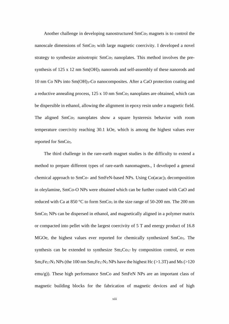
Another challenge in developing nanostructured SmCo5 magnets is to control the
nanoscale dimensions of SmCo5 with large magnetic coercivity. I developed a novel
strategy to synthesize anisotropic SmCo5 nanoplates. This method involves the pre-
synthesis of 125 x 12 nm Sm(OH)3 nanorods and self-assembly of these nanorods and
10 nm Co NPs into Sm(OH)3-Co nanocomposites. After a CaO protection coating and
a reductive annealing process, 125 x 10 nm SmCo5 nanoplates are obtained, which can
be dispersible in ethanol, allowing the alignment in epoxy resin under a magnetic field.
The aligned SmCo5 nanoplates show a square hysteresis behavior with room
temperature coercivity reaching 30.1 kOe, which is among the highest values ever
reported for SmCo5.
The third challenge in the rare-earth magnet studies is the difficulty to extend a
method to prepare different types of rare-earth nanomagnets., I developed a general
chemical approach to SmCo- and SmFeN-based NPs. Using Co(acac)3 decomposition
in oleylamine, SmCo-O NPs were obtained which can be further coated with CaO and
reduced with Ca at 850 °C to form SmCo5 in the size range of 50-200 nm. The 200 nm
SmCo5 NPs can be dispersed in ethanol, and magnetically aligned in a polymer matrix
or compacted into pellet with the largest coercivity of 5 T and energy product of 16.8
MGOe, the highest values ever reported for chemically synthesized SmCo5. The
synthesis can be extended to synthesize Sm2Co17 by composition control, or even
Sm2Fe17N3 NPs (the 100 nm Sm2Fe17N3 NPs have the highest Hc (>1.3T) and Ms (>120
emu/g)). These high performance SmCo and SmFeN NPs are an important class of
magnetic building blocks for the fabrication of magnetic devices and of high

xiv
performance nanocomposite magnets.
My research further extended to non-rare earth magnetic NPs, such as hexagonal
BaFeO NPs. These NPs were prepared by annealing of barium doped iron oxide NPs
at 700 °C in air. They are ferromagnetic with room temperature Hc reaching 5260 Oe
and Ms at 54 emu g−1. I developed a self-assembly method to allow these BaFeO NPs
to form 2D magnetic arrays, which may serve as a unique model system for
nanomagnetic applications.

xv
Table of Contents
Chapter 1. Introduction to Nanomaterials, Magnetism and Magnetic Nanoparticle
Applications.……………….………………………….….……………………..…....1
1.1 General Introduction to Nanomaterials….…………….……...….….…...…..2
1.2 Introduction to Nanomagnetism …………………….…….……………..…..5
1.2.1 Classification of Magnetism .................................................................. 5
1.2.2. Size, Shape, Structure and Temperature Effect of Ferromagnetic
Nanoparticles…………………………………………………………………6
1.2.3. Applications of Ferromagnetic Nanoparticles .................................... 12
References…………………………………...…………………………………...20
Chapter 2. Synthesis and Characterization of Magnetic Nanoparticles………….24
2.1 Chemical Synthesis of Monodisperse Nanoparticles...………………....…….25
2.1.1 Nanoparticles Growth Mechanism ………………..……………………25
2.1.2 Experiment Setup …………………...……………………...…………..27
2.1.3 Nanoparticle Collection and Purification …………………..…………..29
2.2 Nanoparticle Characterization………………………….………….…. ……...30
2.2.1 Transmission Electron Microscopy (TEM)……...……………………...30
2.2.2 Scanning Electron Microscopy (SEM) …………………...…………….31
2.2.3 Scanning Transmission Electron Microscopy (STEM)…………..…….31
2.2.4 X-ray Powder Diffraction Pattern (XRD)…………………………........32
2.2.5 Inductive Coupled Plasma - Atomic Emission Spectroscopy (ICP-AES)32
2.2.6 Magnetic Measurements………………………….…………………….32

xvi
References………………………………………………………………………...34
Chapter 3. Stabilization of Fe Nanoparticles in SmCo5 matrix to Synthesize
SmCo5-Fe Nanocomposites………………..…….……………………36
3.1 Introduction……………………………………………………………….…...37
3.2 Experimental Details……………………………………………….………….39
3.3 Results and Discussion…………………………………….………….……….41
3.3.1 Synthesis and Characterization of Fe/SiO2 Nanoparticles …….………41
3.3.2 Synthesis and Characterization of SmCo5 Hard Magnet………...……..43
3.3.3 Embedding Fe Nanoparticles into SmCo5 Matrix for Nanocomposite
Fabrication……………………………………………………………...45
3.4 Conclusion……………………………………………………….………........49
References……………………………………………………….………………...51
Chapter 4. Synthetic of Anisotropic SmCo5 Nanoplates as Hard Nanomagnets…54
4.1 Introduction…………………………………………………….……………...55
4.2 Experimental Details……………………………………………………….….56
4.3 Results and Discussion………………………………………………………..60
4.3.1 Synthesis of Sm(OH)3-Co Nanocomposites……….…………...………60
4.3.2 Synthesis of SmCo5 Nanoplates……….……………………..………..61
4.3.3 Alignment of SmCo5 Nanoplates in Polymer…………………............66
4.4 Conclusion………………………………………………………………….....69
References…………………………………………………………………………71
Chapter 5. A General Method to Synthesize Anisotropic Sm-based Nanomagnets

xvii
with Ultra-large Coercivity…………………………………..….……..74
5.1 Introduction ………………………………………………….………………..75
5.2 Experimental Details…………………………………………………………..76
5.3 Results and Discussion………………………………………….….………….78
5.3.1 Synthesis of SmCo5 Nanoparticles with Size Control…………….……78
5.3.2 Alignment of SmCo5 in Polymer Matrix and Compaction of SmCo5 to
Pellet………………………………………….………………………….83
5.3.3 Synthesis of Sm2Co17 Nanoparticles and Sm2Fe17N3 Nanoparticles…...86
5.4 Conclusion………………………………………………………………..........89
References…………………………………………………………………………91
Chapter 6. Synthesis and Self-Assembly of Non-rare Earth Permanent
Nanomagnets……………………….…………………………………...94
6.1 Introduction………………………………………………………….…….......95
6.2 Experimental Details……………………………………………….……….....96
6.3 Results and Discussion…………………………………………………………98
6.3.1 Synthesis of Ba doped Iron Oxide (BaFeO) Nanoparticles with
Composition Control …………98
6.3.2 Self-assembly of BaFeO Nanoparticles……..…………..……….…....103
6.4 Conclusion…………………………………………………………………....105
References…………………………………………………………….……….106

xviii
List of Figures
Figure 1-1. Illustration of various objects in nanometer (nm)………………………...3
Figure 1-2. The relationship between the number of atoms in cluster nanoparticles
and the percentage of surface atoms…………………………………………………...4
Figure 1-3. Schematic illustrating the arrangements of magnetic moment for five
different types of materials in the absence or presence of an external magnetic field…6
Figure 1-4. (a) Schematic illustration of the hysteresis loops of ferromagnetic NPs and
(b) superparamagnetic NPs………………………….…………………………………8
Figure 1-5. Schematic illustration of size-dependent Hc of a ferromagnetic particle...8
Figure 1-6. Schematics of the local structures of (a) fcc-FePt and (b) fct-FePt………10
Figure 1-7. Hysteresis loops (a) unaligned and (b) aligned Co NRs. TEM images of (c)
unaligned and (d) aligned Co NRs................................................................................11
Figure 1-8. Illustration of temperature effect to magnetic NPs. The double well
potential shows the energy versus the orientation of the moment of magnetic NPs
without external field………………………………………………………………...12
Figure 1-9. Converting M-H hysteresis loop to B-H hysteresis loop………………..13
Figure 1-10. Magnetic characterization of (a) non-exchange-coupled system and (b)
well exchange-coupled system in magnetic soft and hard composites………………14
Figure 1-11. The fabrication process of fct-FePt/Fe3Pt magnetic nanocomposite…..15
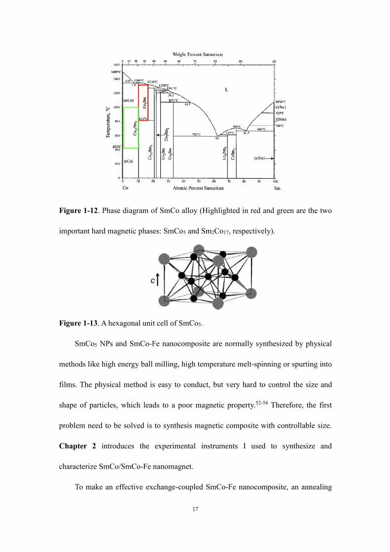
Figure 1-12. Phase diagram of SmCo alloy………………….……………………....17
Figure 1-13. A hexagonal unit cell of SmCo5……………….……………………….17
Figure 2-1. (a) The process of the La Mer model for NPs formation. (b) a characteristic

xix
experimental setup for the organic phase solution synthesis…………………………26
Figure 2-2. Photograph is the typical setup for the organic solution synthesis……....28
Figure 2-3. Photograph for the furnace for high temperature annealing…………….29
Figure 2-4. Photograph for the synthesized green SmCoO NPs in hexane………….30
Figure 2-5. Photograph for the magnetic measurement setup: vibrating sample
magnetometry and physical property measurement system………………………….33
Figure 3-1. (a) TEM image of the as-synthesized 12 nm Fe NPs; (b) XRD pattern of
the as-synthesized 12 nm Fe NPs, showing the typical pattern that matches with the
standard bcc-Fe pattern; (c) TEM image of the 12 nm Fe NPs coated with 7 nm thick
SiO2 shell………………………………………………………………….………….42
Figure 3-2. TEM image of the Sm(OH)3 nanorods (a) and Co(OH)2 nanoplates (b); (c)
XRD of the SmCo5 powder obtained from our chemical synthesis (black curve) and
from the standard pattern (red lines, JPCDS No. 65-8981); (d) Hysteresis loop of the
SmCo5 powder measured at 300 K…………………………………………………...44
Figure 3-3. (a) XRD of hexagonal crystalline Co(OH)2 nanoplate precipitation and
standard pattern of Co(OH)2. (b) XRD of 60nm x15nm crystalline Sm(OH)3 nanorods
and standard pattern of Sm(OH)3……………………………………….……………45
Figure 3-4. (a) XRD patterns of SmCo5-Fe(x wt%) composite with x = 0, 5, 10 and 20.
(b) HAADF-STEM image and (c) elemental mapping of the SmCo5-Fe(10 wt%)
composite. Note: the overall Fe NP content is in 10 wt%, but the image shows an area
enriched with Fe NPs………………………………………………………………..47
Figure 3-5. (a) Hysteresis loops of the nanocomposites of SmCo5-Fe(x wt%) (x = 0-20)

xx
nanocomposites at 300 K. Inset: the change of Hc and Ms with the different Fe NP
contents in the SmCo5-Fe nanocomposites; (b) Hysteresis loops of the nanocomposite
of SmCo5-Fe(10 wt%) before (black) and after (red) 1.5 GPa compaction at 300 K..48
Figure 3-6. A photograph of compressed SmCo5-Fe nanocomposite……………….49
Figure 3-7. Hysteresis loops of the nanocomposites of SmCo5 + 20 wt. % Fe
nanocomposites before and after 1.5 GPa press at 300K. The Ms increases from 78.6
emu/g to 82.7 emu/g. Coercivity decreases from 11.2kOe to 8.1kOe……………….49
Figure 4-1. Schematic illustration of the synthesis of anisotropic SmCo5 nanoplates by
self-assembly of Sm(OH)3 NRs and Co NPs, followed by CaO coating and reductive
annealing…………………………………………………………………………..…56
Figure 4-2. (a) TEM image of the as-synthesized 10 nm Co NPs. (b) XRD of the as-
prepared Co NPs and the standard fcc-Co. (c) TEM image of 125 x 12 nm Sm(OH)3
NRs. (d) XRD of the as-prepared Sm(OH)3 NRs and the standard pattern of Sm(OH)3
......................................................................................................................................61
Figure 4-3 (a) TEM image of Sm(OH)3-Co nanocomposite with Sm:Co =1:4.5 (molar
ratio). (b) TEM image of Sm(OH)3-Co nanocomposite embedded in CaO matrix. (c)
TEM image of Sm(OH)3-Co nanocomposite obtained 10 min after the annealing. (d)
TEM image of the as-synthesized SmCo5 nanoplates. (e) HAADF-STEM and elemental
mapping of the SmCo5 nanoplates, showing the formation of uniform alloy structure
within each nanoplate…………………………………………………………………63
Figure 4-4. (a) TEM image of Sm(OH)3 NRs embedded in Co(OH)2 matrix. (b) TEM
image of SmCo5, showing no specific shape feature…………………………………64

xxi
Figure 4-5. (a) HRTEM image of a part of one SmCo5 nanoplate (planar view). (b) Fast
Fourier transform pattern of (a). (c) Simulated SAED pattern of hexagonal SmCo5
projected along the c-axis. (d) A fraction of HRTEM imaging area in showing the
arrangement of Sm and Co atoms. (e) Modeled hexagonal SmCo5 structure projected
along the c-axis. (f) HRTEM image of the side-view of a SmCo5 nanoplate. (g) Modeled
SmCo5 structure projected along [1, -1, 0]……………………………………………65
Figure 4-6. (a) XRD of the as-synthesized SmCo5 nanoplate powder (black curve) and
the standard pattern of D2d structure SmCo5 (red lines, JPCDS No. 65-8981). (b)
hysteresis loop of the as-synthesized SmCo5 nanoplate powder measured at 300 K…66
Figure 4-7. XRD pattern of SmCo5 nanoplates obtained from their ethanol dispersion
after ethanol evaporation under a 20 kOe field………………………………………68
Figure 4-8 (a) Schematic illustration of SmCo5 nanoplate alignment in resin along the
magnetic field direction for TEM and XRD characterizations. (b) TEM image of the
aligned SmCo5 nanoplates embedded in resin. (c) XRD patterns of the non-aligned
SmCo5 and the aligned SmCo5 nanoplates (red curve). (d) Room temperature hysteresis
loops of the aligned SmCo5 nanoplates measured along the c axis and perpendicular to
the c axis………………………………………………………………………………68
Figure 5-1. TEM images of as-synthesized (a) 60 nm (b) 110 nm (c) 220 nm SmCoO
flower-liked NPs. (d) XRD patterns of SmCoO NPs with different sizes and standard
CoO pattern (JPCDS No. 80-0075). (e) HADDF-STEM image and elemental mapping
of Sm (red), Co (blue) and O (green)………………………………………………...80
Figure 5-2. TEM image of 100 nm SmCoO NPs in CaO matrix coating……………82

xxii
Figure 5-3. TEM image of 100 nm SmCoO NPs after 15 min annealing at 850 °C…82
Figure 5-4. TEM images of annealed (a) 50 nm (b) 100 nm (c) 200 nm polyhedral
SmCo5 NPs. (d) HRTEM of a part of a 100 nm SmCo5 particle. (e) HADDF-STEM
image of a 100 nm SmCo5 particle and elemental mapping of Sm (red) and Co (blue),
showing uniform elemental distribution. (f) XRD patterns of SmCo5 NPs and standard
SmCo5 pattern (JPCDS No. 65-8981). Non-aligned hysteresis loops of (g) 50 nm (h)
100 nm and (i) 200 nm SmCo5 NPs at 300 K………………………………………..83
Figure 5-5. (a) Hysteresis loops of 50 nm, 100 nm and 200 nm SmCo5 NPs after
external field alignment with PEG at 300 K. (b) A picture of compacted SmCo5
nanomagnet. (c) SEM of the SmCo5 nanomagnet after compaction. (d) Hysteresis loops
of compacted 200 nm SmCo5 nanomagnet at 300 K…………………………..…….85
Figure 5-6. B-H hysteresis loops of aligned 200 nm SmCo5 NPs at 300 K…………85
Figure 5-7. (a) TEM image of 120 nm SmCo8.5O NPs. (b) TEM image of 100 nm
Sm2Co17 NPs. (c) XRD patterns of Sm2Co17 NPs and standard hexagonal Sm2Co17
pattern. (d) Hysteresis loop of unaligned and aligned as-synthesized Sm2Co17 NPs at
300 K……………………………………………………………………..…………..87
Figure 5-8. (a) TEM image of a 120 nm SmFeO nanocubes (b) XRD of as-prepared
Sm2Fe17 NPs (black curve) and the standard pattern of rhombohedral structure Sm2Fe17
(red lines, JPCDS No. 01-074-7186). (c) Hysteresis loops of as-prepared 100 nm
Sm2Fe17 NPs at 300 K. (d) TEM of 100 nm Sm2Fe17N3 NPs. (e) XRD of as-prepared
Sm2Fe17N3 NPs (black curve) and the standard pattern of rhombohedral structure
Sm2Fe17N3 (red lines, JPCDS No. 00-048-1790). (f) Hysteresis loops of unaligned

xxiii
(black) and aligned (red) nitrogenized Sm2Fe17N3 NPs at 300 K……………………88
Figure 5-9. XRD of Sm2Fe17 NPs annealed with melamine at 650 oC for 2h (black
curve). The product matches well to standard SmN (red lines) and standard bcc-Fe (blue
lines)………………………………………………………………………………….89
Figure 6-1. (a) TEM image of the as-synthesized Ba0.04–Fe–O NPs. (b) HR-TEM image
of a representative Ba0.04–Fe–O NP. (c) TEM image of the as-synthesized Ba0.082–Fe–O
NPs……………………………………………………………………………….100
Figure 6-2. (A) XRD patterns and (B) room temperature hysteresis loops of the Ba0.04–
Fe–O NPs before and after O2 annealing treatment. (C) XRD patterns and (D) room
temperature hysteresis loops of the Ba–Fe–O NPs with different Ba compositions after
annealing in O2 at 700 °C for 1 h………………………………………………..….102
Figure 6-3. (A) TEM image of the monolayer assembly of Ba0.082–Fe–O NPs. (B) SEM
image of the monolayer assembly deposited on a Si substrate. (C) SEM image of the
monolayer assembly after annealing in O2 at 700 °C for 1 h. (D) SEM images of the
multilayer assembly of Ba0.082-Fe-O NPs deposited on a Si substrate by the drop-casting
method. (E) SEM image of the multilayer assembly after annealing in O2 at 700 °C for
1 h. (F) Room temperature hysteresis loops of the multilayer assembly after annealing
in O2 at 700 °C for 1 h……………………………………………………………….104

xxiv
List of Tables and Schemes
Table 1-1. Dc (Dsd) and superparamagnetic critical size Ds (Dsp) values of common
magnetic materials…………………………………………………………………….8
Table 1-2. A list of parameters of common hard magnetic materials…………………15
Scheme 3-1. Schematic illustration of the synthesis of SmCo5-Fe nanocomposite by
assembling Sm(OH)3 nanorods, Co(OH)2 nanoplates and Fe/SiO2 NPs, followed by
reductive annealing, NaOH solution washing and compaction……………………...38
Table 4-1. A list of SmCo5 made by chemical method. The theoretical calculated
(BH)max for perfect SmCo5 is 28.6 MGOe.
Table 6-1. Experimental conditions for synthesizing Ba–Fe–O NPs with different Ba
compositions……………………………………………………………………...…101

1
Chapter 1
Introduction to Nanomaterials, Magnetism and Magnetic
Nanoparticle Applications

2
1.1 General Introduction to Nanomaterials
The original concept of “Nanomaterial” was first discussed by the famous
American theoretical physicist Richard Feynman, giving a talk entitled “There are
plenty of room at the bottom” which describes that the molecular machines can be built
with atomic precision at the California Institute of Technology in 1959.1 In 1974,
Japanese scientist Norio Taniguchi firstly used the word “Nanotechnology” in his paper
to describe semiconductor processes with precise control at nanometer level,2 and
American engineer Kim Eric Drexler extended the concept to molecular
nanotechnology3.
The modern nanotechnology made a real breakthrough in 1981, when Gerd Binnig
and Heinrich Rohrer at IBM invented the scanning tunneling microscopy (STM). The
characterization instrument makes it possible to observe and operate materials in
individual atom scale. Since then, nanotechnology has been a popular area not only for
fundamental research but also for practical applications.4-10 One nanometer (nm) is one
billionth (10-9) of a meter (m). The scale of nanometer can be straightly shown in Figure
1-1[4] For example, the size of a tennis ball is about 108 nm (ten to the eighth); a
biological cell is in a range of 104 ~ 105 nm; protein, DNA and virus are in a range of 1
~ 102 nm. Typically, nanoparticles (NPs) is a class of particles between 1 ~ 1000 nm in
size.

3
Figure 1-1. Illustration of various objects in nanometer (nm).
Nanomaterials, compared with their bulk counterparts, show very different
physical and chemical properties. The reason is called “size-dependent effect”. The
effect directly leads to dramatic change in surface area of materials. Here is a simple
example. Imagining a solid cubic material with the length of 1 cm, its corresponding
surface area is 6 cm2. If the cube is divided into 1 mm small cube, 1000 small cubes
can be obtained, and the total surface area is 60 cm2. If the 1 cm cube further divided
into 1 nm nanocubes, the total cube number is 10,000,000 and the total surface area
increases to 60,000,000 cm2. The size effect in material can also affect the percentage
of surface atoms. For example, in Figure 1-2, if the atoms in a cluster decreases from
561 to 13, the surface atoms percentage increases greatly from 45% to 92%.11

4
Figure 1-2. The relationship between the number of atoms in cluster nanoparticles and
the percentage of surface atoms.
The physical and chemical differences between the surface atoms and the inner
ones are totally different. The inner atoms, due to their fully coordinated structure,
perform similar properties as bulk materials. Nevertheless, the unsaturated surface
atoms are much less stable than the inner ones and owns a high surface energy. The
highly active surface atoms provide large space and numerous sites for chemical
reaction with different kinetic mechanism, which is very important for catalysis
application of NPs.12-15 Also, the size effect also be found in nanoscale semiconductors
(known as quantum dots). The size of quantum dots directly affects the band gap, and
as a result, the optical properties can be rationally adjusted and show great potential in
the fields of biological labeling, photovoltaics and solid-state lighting.16-19 Apart from
the catalysis and optical applications mentioned above, the magnetic application of NP
is also one of the most noteworthy and promising field in the current technology, which

5
will be discussed in detail below.
1.2 Introduction to Nanomagnetism
1.2.1 Classification of Magnetism
Magnets have been widely used over thousands of years. In modern history, the
applications of magnetic materials can be found in electronic and magnetic devices,
such as motors, computers, medical equipment and so on. The magnetism is originally
from the electron magnetic moment, which is result of the orbital and spin
magnetization coupling of an electron. According to the interaction of atomic magnetic
moments, materials can be classified into diamagnetic, paramagnetic, ferromagnetic,
ferrimagnetic, and antiferromagnetic.20-22
Figure 1-3 shows schematic diagrams of these five different states. Diamagnetic
materials are consisted of atoms which have no single electrons. Their paired electrons
have no net magnetic moments in the absence of magnetic field. In paramagnetic
materials, some single electrons partially fill the orbitals. In the absence of external field,
the spins are randomly oriented due to thermal fluctuation. If an external magnetic field
applied, those atomic magnetic moments will align in the directions of the field in some
extent, resulting in a net but very weak magnetization. The ferromagnetic materials
show a totally different magnetism. The strong interaction of the atomic moment,
produced by electronic exchange force, lead to a parallel alignment of the atomic
moments. The ferromagnetic materials show a large net magnetization even without
external field alignment. The ferrimagnetic materials own two magnetic sublattices.

6
These two set of sublattices are antiparallelly aligned, which caused by super-exchange
coupling effect. However, the magnetic moment of one set is stronger than another set
and an existing net magnetic moment exist, showing similar magnetic behavior to
ferromagnetism. Antiferromagnetic materials also have two sublattices, antiparallelly
aligned to each other. However, they have the same magnetic moments and cancel each
other, resulting in no net magnetization. Generally, only ferromagnetic or ferrimagnetic
materials are called magnetic materials.
Figure 1-3. Schematic illustrating the arrangements of magnetic moment for five
different types of materials in the absence or presence of an external magnetic field.
1.2.2 Size, Shape, Structure and Temperature Effect of Ferromagnetic NPs
The behavior of magnetic NPs can be described by hysteresis loop, as shown in
Figure 1-4 (a). In the absence of external magnetic field, the NPs are randomly aligned,
and the total moment is 0. If an external field applied, the interaction of magnetic NPs
and field can align the moment of NPs to the field direction. If the external field is

7
strong enough, all the particles will turn to field direction and the corresponding
moment reaches the maximum value, which is defined as saturation moment (Ms). The
total moment will also decline with decreasing the external field. But when the field
reduces to 0, the magnetic NPs can still hold an extent of moment, which is called
remnant moment (Mr). To fully demagnetize the NPs, a reverse field should be added
to the point where the total moment is 0, the value of which is named as coercivity (Hc).
The magnetic properties, especially Hc, are strongly size-dependent.23,24 As shown in
Figure 1-5, if the size of magnetic particle is in single domain (SD) range, the moment
doesn’t change direction across the particle. The coercivity increases with growing size
and can reach to a maximum value and the size is called critical size (Dc). The Dc values
for a spherical magnetic NP can be roughly calculated as Dc ≈36√𝐴𝐾
𝜇0𝑀𝑠2 , where A is the
exchange constant, K is the anisotropy constant which stands for the energy per unit
volume required to flip moment direction, μ0 is the vacuum permeability, and Ms is the
saturation moment. The Dc values are usually in the range of 5-1000 nm. The Dc values
of some commercial used magnetic materials are listed in Table 1. If the particle size is
larger than Dc, multi-domains (MD) exist in the particle. Because of the domain-domain
interaction, a moderately low external field is needed to change the magnetization. And
the Hc will decrease with increasing the size. On the other hand, if the particle is
extremely small, the thermal fluctuation effect become obvious and cause the moment
of NPs to flip direction. As a result, the ferromagnetic NPs turn to superparamagnetic
(Figure 1-4 (b)). Once the external field is removed, the magnetic NPs will be randomly
aligned leaving no Mr and Hc.

8
Figure 1-4. (a) Schematic illustration of the hysteresis loops of ferromagnetic NPs and
(b) superparamagnetic NPs.
Figure 1-5. Schematic illustration of size-dependent Hc of a ferromagnetic particle.
Table 1-1. Dc (Dsd) and superparamagnetic critical size Ds (Dsp) values of common
magnetic materials.

9
The structure and shape effect of magnetic NPs are also very important. Crystal
structure directly influences intrinsic spin−orbital moment interaction, which can be
expressed as magnetocrystalline anisotropy. The value of magnetocrystalline anisotropy
constant (K) determine the coercivity of magnetic NPs. Theoretically, if the material
owns a large intrinsic anisotropy constant, the material can obtain a large coercivity. For
example, the equal-atomic FePt alloy present two distinctive crystal structures (Figure
1-6). One shows face-centered cubic (fcc) structure (Figure 1-6a), in which the Fe and
Pt atoms randomly occupy the lattice points, forming a solid solution. The fcc-FePt is
magnetically isotropic, displaying superparamagnetic property. The other shows
chemically ordered face-centered-tetragonal (fct) structure (Figure 1-6b). The Fe and
Pt atom layers stacks alternatively along the [001] direction.25,26 Because of the strong
coupling of 3d orbital from Fe and 5d orbital from Pt, the fct-FePt has a large anisotropy
constant K (up to 7 × 10⁶ J/m3) and are strongly ferromagnetic with a coercivity larger
than 3 T.

10
Figure 1-6. Schematics of the local structures of (a) fcc-FePt and (b) fct-FePt.
The shape of magnetic NPs also affects the magnetic properties. If a NP is sphere-
shaped, there will be have no shape anisotropy and the magnetic property has no change
in different directions. But if magnetic NPs are prepared in specific shape (rods, plates),
their magnetic properties measured from the magnetic easy and hard direction are
different. Generally, the hysteresis loop obtained from magnetic easy axis owns a high
Mr, a large Hc and a better squareness compared with that from hard axis. For example,
the Co NPs less than 15 nm usually shows a coercivity less than 1 kOe. However, the
Co nanorods (NRs) with the diameter of 15 nm and length-width ratio of 10, after
magnetic alignment, own a Hc of 4.5 kOe along magnetic easy direction at room
temperature (Figure 1-7).27 The shape anisotropy effect is very important to fabricate
magnetic media in high density tape recording.

11
Figure 1-7. Hysteresis loops (a) unaligned and (b) aligned Co NRs. TEM images of (c)
unaligned and (d) aligned Co NRs. Copyright 2009 Wiley.
The magnetic properties are also temperature-dependent. If the temperature of
magnetic material is above a critical temperature, the NPs will lose ferromagnetism and
transits to superparamagnetic. The critical temperature is called Curie temperature (Tc).
The mechanism can be illustrated in Figure 1-8, which shows the energy barrier
between the “up” and “down” moment in a NP. The energy needed to turn the moment
to an inverse direction is KV. If temperature increases, the thermal energy kBT (kB is
Boltzmann constant) would become stronger. If the temperature is above Tc, kBT will
overcome the energy barrier, causing a randomization of moment in NPs. Tc is an
intrinsic property which determines the upper limit temperature of ferromagnetic
material application. Generally, most magnetic materials have a negative temperature
coefficient, which means the coercivity of magnetic NPs will decrease with increasing

12
temperature. But there are still a few materials (like MnBi) own a positive temperature
coefficient and their coercivity will increase with increasing temperature until reaching
to Tc.
Figure 1-8. Illustration of temperature effect to magnetic NPs. The double well
potential shows the energy versus the orientation of the moment of magnetic NPs
without external field.
1.2.3. Applications of Ferromagnetic NPs
Ferromagnetic NPs have a wide application as recording media in hard disk drive
(HDD), in biochemistry and electrochemistry catalysis. Among them, one of the most
important and promising application is to fabricate permanent magnets for energy
storage and conversion, as that in the direct-current motors and wind turbines.28-39 The
permanent magnet can keep a high Mr and generate a magnetic field after magnetization.
Also, the large Hc of permanent magnet can stabilize the magnetic field for long-time
use. To evaluate the magnetic energy storage capacity of a permanent magnet, a figure-
of-merit is introduced as the maximum energy product (BH)max. To calculate the value

13
of (BH)max, first the M-H hysteresis loop was converted to B-H hysteresis loop with
an equation of B = H + 4πM (Figure 1-9), where B is called magnetic induction. The
(BH)max corresponds to the area of the largest rectangle in the second quadrant of the
B-H hysteresis loop. The unit is kJ/m3 (SI) or MGOe (GCS). Therefore, to obtain the
optimum magnetic property, the material should own both large coercivity and high
moment.
Figure 1-9. Converting M-H hysteresis loop to B-H hysteresis loop.
However, traditional magnetic materials, such as Fe and Co, have a high moment
but a small coercivity (less than 1000 Oe at room temperature), which we call them as
“soft magnet”.40,41 While another type materials called “hard magnet”, like NdFeB,
SmCo5 and fct-FePt, have a large coercivity (larger than 1000 Oe) but relatively low
moment.42-45 If the advantages of both hard and soft magnet can be combined in one
material, the (BH)max will be enhanced. And exchange coupling provides a promising
method to achieve the goal. The illustration of an exchange-coupled magnetic system
is shown in Figure 1-10. The requirements for effective exchange coupling between the
two phases are very strict.46,47 First of all, the hard magnet and soft magnet much be in
close contact with each other. Secondly and the most importantly, the size of the soft
phase must be small enough (~10 nm). If the requirement is not satisfied, the composite

14
will be decoupled and the hysteresis loop will show magnetic two-phase behavior,
which decreases the (BH)max (Figure 1-10A). Just the interface between the hard and
soft magnets is effective coupled, the majority of the soft would be easily magnetized
and demagnetized. Only with appropriate size of the soft phase will the composite be
effectively exchange couples with enhanced energy storage (Figure 1-10B).
Figure 1-10. Magnetic characterization of (a) non-exchange-coupled system and (b)
well exchange-coupled system in magnetic soft and hard composites.
A successful exchange-coupled nanocomposite of fct-FePt/Fe3Pt has been studied,
which gave scientist a viable way to fabricate magnetic nanocomposite.48 In this work
(Figure 1-11), a self-assembly of FePt and Fe3O4 NPs was annealed under H2 at 650 oC.
After annealing, the fcc-FePt was converted to magnetic hard fct-FePt and Fe3O4 was
reduced to magnetic soft Fe3Pt. The fct-FePt/Fe3Pt nanocomposite showed a smooth
hysteresis loop with enhanced (BH)max of 20.1 MGOe, which is 50 % higher than

15
single hard phase fct-FePt (13 MGOe).
Figure 1-11. The fabrication process of fct-FePt/Fe3Pt magnetic nanocomposite.
Copyright 2002 Nature Publishing Group.
To maximize the (BH)max in magnetic nanocomposite, it is very important to
choose appropriate soft and hard segments. For soft magnetic, the candidates are always
Fe, Co or FeCo alloys with high moment. For the common strong hard phase candidates
(the type and magnetic parameters are shown in Table 1-2),49 if we only considering
(BH)max, the NdFeB is the best one. However, the NdFeB shows a relative low Hc and
a low Tc, hence NdFeB cannot be used as permanent magnet above 200 oC in industry.
Another type of rare-earth hard magnet, SmCo, would be a good substitute of NdFeB.50
For example, the SmCo5 shows a large magnetocrystalline anisotropy constant (K=107
J m-3) and Tc (747 oC), which means it can still keep large coercivity at high temperature.
Therefore, in my Ph.D study I mainly focus on SmCo NPs synthesis and SmCo-Fe
nanocomposite fabrication.
Table 1-2. A list of parameters of common hard magnetic materials.

16
The group of SmCo magnets has been developed since 1970s and exist in several
phases (Figure 1-12).51 Among them, two most important alloys, SmCo5 and Sm2Co17,
shows superior magnetic property. The SmCo5 owns the greatest K value in known
materials up till now. The Sm2Co17 magnets, though showing smaller K value, have
higher saturation moment than the SmCo5. Both have higher Tc than Nd-based magnets
and are widely used in industrial production. If they combine with soft magnets though
exchange-coupling, the Ms will be increase and further improve the (BH)max to form
a magnetic superior nanocomposite. The crystal unit cell of SmCo5 is shown in Figure
1-13. This material adopts a hexagonal CaCu5 structure with Co layers and Sm + Co
layers present alternatively along the c-axis. The c-axis of the lattice is also magnetic
easy direction of SmCo5. The strong ferromagnetic property results from the parallel
coupling of delocalized Co 3d and localized Sm 4f moments.
17
Figure 1-12. Phase diagram of SmCo alloy (Highlighted in red and green are the two
important hard magnetic phases: SmCo5 and Sm2Co17, respectively).
Figure 1-13. A hexagonal unit cell of SmCo5.
SmCo5 NPs and SmCo-Fe nanocomposite are normally synthesized by physical
methods like high energy ball milling, high temperature melt-spinning or spurting into
films. The physical method is easy to conduct, but very hard to control the size and
shape of particles, which leads to a poor magnetic property.52-54 Therefore, the first
problem need to be solved is to synthesis magnetic composite with controllable size.
Chapter 2 introduces the experimental instruments I used to synthesize and
characterize SmCo/SmCo-Fe nanomagnet.
To make an effective exchange-coupled SmCo-Fe nanocomposite, an annealing

18
process is required. However, if SmCo and Fe NPs were simply mixed together and
annealed directly, Fe will diffuse into SmCo matrix to form SmCoFe alloy, not SmCo-
Fe composite, which will decline the magnetic properties. To overcome the difficulty,
Chapter 3 describes a new method to stabilize Fe NPs in SmCo matrix. In the work,
we first synthesize Fe/SiO2 core-shell structure NPs. SiO2 coating can prevent Fe NPs
diffusion or aggregation at high temperature, which can be removed by base and SmCo-
Fe nanocomposite with adjustable magnetic properties can be obtained.
The direct annealing reduction method of SmCo synthesis without control leading
to a low magnetic performance of SmCo5. To solve the problem, Chapter 4
demonstrates a self-assembly method to synthesize anisotropic SmCo5 nanoplates. The
SmCo5 nanoplates can be magnetically aligned and show an obverse magnetic
anisotropy with a Hc reaching to 30 kOe along the alignment direction.
To obtain versatile SmCo NPs with high yield, Chapter 5 describes a general
chemical method to synthesize hard magnets SmCo NPs with tunable sizes (50, 100 and
200 nm) and composition (SmCo5, Sm2Co17), by reducing different sizes of SmCoO
NPs in CaO matrix. The largest coercivity of 200 nm SmCo5 NPs can reach to 50 kOe
after alignment in polymer. This method can also be applied to SmFeN NPs synthesis
and hence stands for a general method of Sm based nanomagnet synthesis.
Non-rare earth magnet is also a class of important permanent magnet due to its
easy availability and low cost. The non-rare earth permanent magnet holds roughly half
of the magnet market and widely used in our daily life. For example, barium ferrite,
work as a recording media in hard drive device due to its comparable large coercivity,

19
chemical stability and relatively cheap price. Chapter 6 discusses the efforts to
synthesize and self-assemble BaFeO NPs for permanent magnet production.

20
References:
1 R. P. Feynman, Eng. Sci., 1959, 23, 22.
2 N. Taniguchi, Proc. Intl. Conf. Prod. Eng. Tokyo, Part II, Japan Society of Precision
Engineering, 1974, 5–10.
3 K.E. Drexler, Nanosystems: Molecular machinery, manufacturing, and computation.
New York: John Wiley & Sons, Inc, 1992.
4 B. D. Gates, Q. B. Xu, M. Stewart, D. Ryan, C. G. Willson, G. M. Whitesides, Chem.
Rev. 2005, 105, 1171-1196.
5 N. L. Rosi, C. A. Mirkin, Chem. Rev. 2005, 105, 1547-1562.
6 E. Boisselier, D. Astruc, Chem. Soc. Rev. 2009, 38, 1759-1782.
7 B. L. Cushing, V. L. Kolesnichenko, C. J. O'Connor, Chem. Rev. 2004, 104, 3893-
3946.
8 M. Haase, H. Schafer, Angew. Chem. Int. Ed. 2011, 50, 5808-5829.
9 A. H. Lu, E. L. Salabas, F. Schuth, Angew. Chem. Int. Ed. 2007, 46, 1222-1244.
10 D. V. Talapin, J.-S. Lee, M. V. Kovalenko, E. V. Shevchenko, Chem. Rev. 2010, 110,
389-458.
11 J. P. Wilcoxon, B. L. Abrams, Chem. Soc. Rev. 2006, 35, 1162-1194.
12 Y. J. Wang, D. P. Wilkinson, J. J. Zhang, Chem. Rev. 2011, 111, 7625-7651.
13 S. Zhang, Y. Z. Hao, D. Su, V. V. T. Doan-Nguyen, Y. T. Wu, J. Li, S. H. Sun, C. B.
Murray, J. Am. Chem. Soc. 2014, 136, 15921-15924.
14 Y. J. Kang, J. Snyder, M. F. Chi, D. G. Li, K. L. More, N. M. Markovic, V. R.
Stamenkovic, Nano Lett. 2014, 14, 6361-6367.

21
15 C. Wang, D. van der Vliet, K. L. More, N. J. Zaluzec, S. Peng, S. H. Sun, H. Daimon,
G. F. Wang, J. Greeley, J. Pearson, A. P. Paulikas, G. Karapetrov, D. Strmcnik, N. M.
Markovic, V. R. Stamenkovic, Nano Lett. 2011, 11, 919-926.
16 D. Ioannou, D. K. Griffin, Nano Rev. 2010, 1, 5117
17 I. L. Medintz, H. T. Uyeda, E. R. Goldman, H. Mattoussi, Nat. Mater. 2005, 4, 435-
446.
18 A. M. Smith, S. M. Nie, Acc. Chem. Res. 2010, 43, 190-200.
19 O. Chen, J. Zhao, V. P. Chauhan, J. Cui, C. Wong, D. K. Harris, H. Wei, H. S. Han,
D. Fukumura, R. K. Jain, M. G. Bawendi, Nat. Mater. 2013, 12, 445-451.
20 R. C. O’Handley, Modern Magnetic Materials: Principles and Applications, Wiley,
New York 2000.
21 N. Spaldin, Magnetic Materials: Fundamentals and Device Applications,
Cambridge University Press, Cambridge, UK 2003.
22 D. Weller, A. Moser, L. Folks, M. E. Best, W. Lee, M. F. Toney, M. Schwickert, J.
U. Thiele, M. F. Doerner, IEEE Trans. Magn. 2000, 36, 10.
23 Y. W. Jun, J. S. Choi, J. Cheon, Chem. Commun. 2007, 1203-1214.
24 B. M. Moskowitz, Hitchhiker's guide to magnetism 1991. 29
25 O. Gutfleisch, J. Lyubina, K. H. Muller, L. Schultz, Adv. Eng. Mater. 2005, 7, 208.
26 D. E. Laughlin, K. Srinivasan, M. Tanase, L. Wang, Scr. Mater. 2005, 53, 383.
27 Y. Soumare, C. Garcia, T. Maurer, G. Chaboussant, F. Fievet, J. Y. Piquemal, G. Viau,
Adv. Funct. Mater. 2009, 19, 1971.
28 J. H. Lee, Y. M. Huh, Y. Jun, J. Seo, J. Jang, H. T. Song, S. Kim, E. J. Cho, H. G.

22
Yoon, J. S. Suh, J. Cheon, Nat. Med. 2007, 13, 95-99.
29 H. B. Na, J. H. Lee, K. J. An, Y. I. Park, M. Park, I. S. Lee, D. H. Nam, S. T. Kim, S.
H. Kim, S. W. Kim, K. H. Lim, K. S. Kim, S. O. Kim, T. Hyeon, Angew. Chem. Int. Ed.
2007, 46, 5397-5401.
30 J. H. Gao, G. L. Liang, J. S. Cheung, Y. Pan, Y. Kuang, F. Zhao, B. Zhang, X. X.
Zhang, E. X. Wu, B. Xu, J. Am. Chem. Soc. 2008, 130, 11828-11833.
31 K. Cheng, S. Peng, C. J. Xu, S. H. Sun, J. Am. Chem. Soc. 2009, 131, 10637-10644.
32 J. T. Jang, H. Nah, J. H. Lee, S. H. Moon, M. G. Kim, J. Cheon, Angew. Chem. Int.
Ed. 2009, 48, 1234-1238.
33 T. Hyeon, J. E. Lee, N. Lee, H. Kim, J. Kim, S. H. Choi, J. H. Kim, T. Kim, I. C.
Song, S. P. Park, W. K. Moon, J. Am. Chem. Soc. 2010, 132, 552-557.
34 D. Ho, X. Sun, S. Sun, Acc. Chem. Res. 2011, 44, 875-882.
35 S. Peng, S. H. Sun, Angew. Chem. Int. Ed. 2007, 46, 4155-4158.
36 S. Peng, C. Wang, J. Xie, S. H. Sun, J. Am. Chem. Soc. 2006, 128, 10676-10677.
37 C. J. Xu, B. D. Wang, S. H. Sun, J. Am. Chem. Soc. 2009, 131, 4216-4217.
38 S. H. Sun, L. L. Lacroix, L. M., N. F. Huls, D. Ho, X. L. Sun, K. Cheng, Nano Lett.
2011, 11, 1641-1645.
39 C. Wang, Y. J. Wei, H. Y. Jiang, S. H. Sun, Nano Lett. 2009, 9, 4544-4547.
40 L. M. Lacroix, N. F. Huls, D. Ho, X. L. Sun, K. Cheng, S. H. Sun, Nano Lett. 2011,
11, 1641-1645.
41 C. Wang, S. Peng, L. M. Lacroix, S. H. Sun, Nano Res. 2009, 2, 380-385.
42 Y. L. Hou, Z. C. Xu, S. Peng, C. B. Rong, J. P. Liu, S. H. Sun, Adv. Mater. 2007, 19,

23
3349-3352. 30
43 S. H. Sun, C. B. Murray, D. Weller, L. Folks, A. Moser, Science 2000, 287, 1989-
1992.
44 J. M. Kim, C. B. Rong, J. P. Liu, S. H. Sun, Adv. Mater. 2009, 21, 906-909.
45 J. Kim, C. Rong, Y. Lee, J. P. Liu, S. Sun, Chem. Mater. 2008, 7242–7245.
46 E. F. Kneller, R. Hawig, IEEE Trans. Magn. 1991, 27, 3588-3600.
47 R. Skomski, J. M. D. Coey, Phys. Rev. B 1993, 48, 15812-15816.
48 H. Zeng, J. Li, J. P. Liu, Z. L. Wang, S. H. Sun, Nature 2002, 420, 395-398.
49 R. Skomski, J. M. D. Coey Permanent Magnetism 1998.
50 H. A. Leupold, F. Rothwarf, J.T. Breslin, J. J. Winter, A. Tauber, D. I. Paul, J
Appl Phys 1982, 53, 2392.
51 H. Okamoto, J Phase Equilib 1999, 20, 535.
52 J. Ding, P. G. McCormick, R. Street, J. Alloys Compd. 1995, 228, 102.
53 S. K. Chen, J. L. Tsai, T. S. Chin, J. Appl. Phys. 1996, 79, 5964.
54 E. M. Kirkpatrick, D. L. Leslie-Pelecky, J. Appl. Phys. 2000, 87, 6734.

24
Chapter 2
Synthesis and characterization of magnetic nanomaterials

25
2.1 Chemical Synthesis of Monodisperse NPs
2.1.1 Mechanism of Monodisperse NPs Growth
To prepare NPs with controlled size, shape and composition is a key step for their
application. Two general ways to prepare NPs are called as “top-down” and “bottom-
up” methods. The “top-down” method means the nanomaterials are crushed from bulk
size materials, which is often refer to physical methods, like mechanical ball milling,
lithography patterning, melt-spinning etc.1,2 The “top-down” method is a facile way but
usually lack of control of the producing monodisperse NPs (usually the size is from
several nanometers to micrometers). The “bottom-up” method refers to chemically
synthesize nanomaterials in atom level. This method includes chemical vapor
deposition (CVD),3 aqueous sol-gel process,4 microemulsion process5 and
hydrothermal synthesis6 and organic solution phase synthesis. The different synthesis
methods own specific advantages. For example, aqueous sol-gel synthesis is easy to
operate and can give a high yield of product; The organic solution phase approach can
precisely control monodisperse NPs in 0.1 nm scale with various shapes7-12 and versatile
structures.13-16 And herein, I mainly focused on the organic solution phase synthesis to
prepare monodisperse NPs and nanocomposites for magnetic applications.
The growth mechanism of NPs can be explained by “La Mer Model” in organic
solution phase synthesis process, which can be illustrated in Figure 2-1a17. In the
process, a vital concentration of precursor is called critical supersaturation or nucleation
threshold. If the concentration of precursor is lower than this level, no nucleation
appears and no NPs form. When the concertation of the precursors is higher than critical

26
supersaturation, large number of nuclei can be formed spontaneously. The spontaneous
nucleation rapidly decreased the concentration of precursors below the critical level in
the solution and hence no further nuclei can be formed. The existing nuclei will grow
into particles by aging at high temperature, which is called Ostwald Ripening process.
In the process, small nuclei will dissolute due to their high surface energy, and the
material will then redeposite on large NPs. The average size will increase with a
reimbursing reduction of the nuclei number.
Figure 2-1. (a) The process of the La Mer model for NPs formation. (b) a characteristic
experimental setup for the organic phase solution synthesis.
Figure 2-1b shows the experimental setup used to prepare NPs in organic solution.
The organic solvents with high boiling point (usually above 200 oC) are often used to
provide a high temperature environment for precursor decomposition. The common
solvents are like 1-octadecene (ODE, bp. 315 oC), benzyl ether (BE, bp. 298 oC),
1,2,3,4-tetrahydronaphthalene (tetralin, bp. 208 oC). In the reaction, usually there are

27
two mechanisms of decomposition of precursors.18-21 One is “hot-injection”, in which
the precursors are fast injected into the pre-heated reactor to reach critical
supersaturation. Another way is “heating-up” the precursors from low temperature to
their decomposition temperature, in which the nucleation process can be controlled by
the heating rate. However, due to high surface energy of NPs, a major problem in
organic solution synthesis is particle aggregation. To stabilize the NPs in the synthesis
process, selected surfactant(s) like oleylamine (OAm) and oleic acid (OAc), should also
be added in the reaction system. The surfactants coating around the NPs will cause steric
repulsion, which can make NPs dispersed in organic solvent for further use.
2.1.2 General Synthesis Setup
A typical synthesis setup I used in our lab is shown in Figure 2-2. Inert gases (N2,
Ar) can be introduced through the Schlenk line to exclude oxygen and water in the flask.
In the synthesis process, the precursors and organic solvent in the flask is stirred by a
magnetic bar. The four-neck flask can be heated by a heating mantle. One neck of the
flask needs to connect to the temperature controller (the thermal couple) for monitoring
the reaction temperature. One is connected to a gas inlet of the Schlenk line and another
is connected to the gas outlet trap, which can collect low boiling point impurity and
byproduct from the reaction. The extra neck is usually covered with a rubber stopper in
case of any chemicals needed to be injected into the reaction system during the reaction.

28
Figure 2-2. Photograph is the typical setup for the organic solution synthesis used in
our lab.
The chemicals used in my synthesis such as the organic solvent, metal salts,
surfactants, and reductive agents were purchased from Strem Chemicals (e.g. metal
acetylacetonate, metallic calcium) or Sigma Aldrich (e.g. iron carbonyl and cobalt
carbonyl) without further purification.
As shown in Figure 1-12, SmCo5 is thermodynamic stable above 820 oC.
Therefore, a high temperature annealing setup is needed. In our lab, we use the furnace
to anneal the sample (Figure 2-3). The quartz or ceramic annealing tubes connecting
with gas inlet and outlet can fill with inert gas (N2, Ar) and reductive gas (forming gas,
95%Ar + 5% H2). The samples in a ceramic or stainless-iron annealing boat are located
at the center of the tube. The temperature, heating speed and time can be automatically
controlled by the program of the furnace.

29
Figure 2-3. Photograph for the furnace for high temperature annealing.
2.1.3 NPs Collection and Purification
When the reaction finished, the products and organic solvent are first transferred
from flask centrifugation tubes. Then certain precipitant is added into the centrifugation.
The precipitants are usually polar solvent such as ethanol, acetone, isopropanol or their
mixture. The as-prepared NPs are coated with a layer of oleic acid and/or oleylamine,
so the hydrophobic end cannot be stably dispersed in polar solvent environment and
will precipitate from the solvent. After the precipitation, the NPs are collected by the
Beckman Coulter Allegra® 64R Centrifuge. Then the NPs can be easily separated by
pouring out the solvent. The remaining NPs attaching on the wall of centrifuge tubes
can be re-dispersed in non-polar solvents such as hexane and toluene. The washing
process should be repeated 2 ~ 3 times to clean the surface of NPs and remove extra
surfactants in the solvent. Here we should also mention that the centrifuge can also be
used for size selection if different sizes of NPs formed. By carefully choosing the speed
and time in the centrifuge process, different sizes NPs can be separated. The final
washed NPs can be dispersed in hexane again for the further use. Figure 2-4 shows the

30
as-synthesized dark green SmCoO NPs dispersion in hexane. The dispersion usually
stable and can be kept in ambient environment. However, some non-noble metal NPs
(e.g. Fe and Co NPs) and alloys (SmCo5) are not compatible with oxygen which can be
gradually oxidized in air. These NPs should be stored in glove box full of Ar for long-
term use.
Figure 2-4. Photograph for the synthesized green SmCoO NPs in hexane.
2.2 NPs Characterization
Various of characterization techniques are needed to explore the properties of the
as-prepared NPs. The typical characterization methods I used during my Ph. D. study
are listed below.
2.2.1 Transmission Electron Microscopy (TEM)
Transmission Electron Microscopy (TEM) is the most common equipment applied
to illustrate the shape and morphology of as-synthesized NPs. The TEM images were
recorded from a Philips CM20 Microscopy with an operating voltage of 200 kV at
Brown University. The sample can be prepared by depositing a droplet of NP dispersion
on a carbon coated Cu TEM grid (Ted Pella) for TEM analysis. High-Resolution

31
Transmission Electron Microscopy (HRTEM) is a more powerful instrument, which
allows direct observation of crystal lattice of the NPs. HRTEM images were collected
by using a JEOL 2010 with an accelerating voltage of 200 kV. The sample preparation
process is the same as that in regular TEM test.
2.2.2. Scanning Electron Microscopy (SEM)
Scanning electron microscopy (SEM) is another important instrument to
characterize the size and morphology of NPs. Compared with TEM, the SEM has a
lower resolution, but it can be applied to bulk material characterization. SEM images
were obtained on a LEO 1530 microscope at an accelerating voltage of 10 kV. To make
a n SEM sample, the material can be deposit on a conductive substrate such as Si wafer.
Besides the morphology analysis, the SEM can perform elemental analysis with the
help of the equipped energy-dispersive X-ray (EDX) spectroscopy. This EDX can
analyze X-ray emission spectrum of the elements and thus work as an instrument to
check elements existence in the specimen.
2.2.3 Scanning Transmission Electron Microscopy (STEM)
Scanning transmission electron microscopy (STEM) is a type of advanced TEM.
The difference is in STEM the electron beam can focus on a tiny spot (0.05 ~ 0.2 nm)
and then scanned over the sample in a raster. STEM can be suitable for unique analytical
techniques such as high-angle annular dark-field imaging (HAADF), elemental
mapping analysis, and electron energy loss spectroscopy (EELS). My STEM analysis

32
work was done on a Hitachi HD2700C (200 kV) with a probe aberration corrector, at
the Center for Functional Nanomaterials, Brookhaven National Lab.
2.2.4 X-Ray Diffraction (XRD)
X-ray diffraction (XRD) technique is a very critical tool to determine the crystal
structure and chemical composition of as-prepared NPs. For magnetic NPs, the XRD
can even characterize the magnetic NPs alignment direction. The XRD patterns are
collected by a Bruker AXS D8-Advanced diffractometer with Cu Kα radiation (λ =
1.5418 Å). The XRD sample can be prepared by drying NP dispersion or depositing
powders on the glass or silicon slide. Moreover, using Scherrer equation, the size of the
NPs can be roughly determined.
2.2.5 Inductively Coupled Plasma Atomic Emission Spectroscopy (ICP-AES)
Inductively coupled plasma atomic emission spectroscopy (ICP-AES) is a precise
measurement technique for quantitative detection of chemical elements. In my work,
all ICP-AES measurement was recorded by a JY2000 Ultrace ICP atomic emission
spectrometer equipped with a JYAS 421 autosampler and 2400 g/mm holographic
grating at Brown University. To make samples, tiny amount of NPs were totally
dissolved in 2 ml aqua regia (VHNO3 : VHCl = 1 : 3) and dried by heating. Subsequently,
2 % HNO3 was added to dissolve the precipitate for ICP-AES test.
2.2.6. Magnetic Measurements

33
Magnetic properties of NPs were evaluated by a vibrating sample magnetometry
(VSM, LakeShore 7404) with a maximum field of 1.5 T in our group. The magnetic
NPs were dried and then transferred into a round-bottled capsule (0.3 mL, Electron
Microscopy Science), and a piece of cotton is pressed firmly into the capsule on top to
fix the magnetic sample. The capsule was placed at the center of the external field to
measure its hysteresis loop. Also, the NPs dispersion can be deposited onto Si substrates.
After solvent evaporation, the NPs form a film and the magnetic property can be
measured in-plane and out-of-plane. The VSM can measure the hysteresis loops of Fe,
Co and ferrite, but the field is not strong enough to measure rare-earth containing alloy
like SmCo5. In this case, a physical property measurement system (PPMS) with a field
up to 9 T from Physics Department at Brown and a PPMS with a field up to 14 T in
Lawrence Livermore National Laboratory (LLNL) was used (Figure 2-5).
Figure 2-5. Photograph for the magnetic measurement setup: vibrating sample
magnetometry (left) and physical property measurement system (right).

34
References:
1 A. Calka, D. Wexler, Nature 2002, 419, 147.
2 Y. Zhang, L. Zhang, C. Zhou, Acc. Chem. Res., 2013, 46, 2329.
3 T. P. Yadav, R. M. Yadav, D. P. Singh, Nanoscience and Nanotechnology 2012, 2,
22.
4 J. Yang, D. Yan, T. S. Jones, Chem. Rev. 2015, 115, 5570.
5 S. Peng, Y. Lee, C. Wang, H. Yin, S. Dai, S. Sun, Nano Res. 2008, 1, 229.
6 B. L. Cushing, V. L. Kolesnichenko, C. J. O'Connor, Chem. Rev. 2004, 104, 3893.
7 W. Zhu, R. Michalsky, O. Metin, H. Lv, S. Guo, C. J. Wright, X. Sun, A. A. Peterson,
S. Sun, J. Am. Chem. Soc. 2013, 135, 16833.
8 W. Zhu, Y. Zhang, H. Zhang, H. Lv, Q. Li, R. Michalsky, A. A. Peterson, S. Sun, J.
Am. Chem. Soc. 2014, 136, 16132.
9 C. Wang, H. Daimon, T. Onodera, T. Koda, S. Sun, Angew. Chem. Int. Ed. 2008, 47,
3588.
10 N. Yang, Z. Zhang, B. Chen, Y. Huang, J. Chen, Z. Lai, Y. Chen, M. Sindoro, A.
Wang, H. Cheng, Z. Fan, X. Liu, B. Li, Y. Zong, L. Gu, H. Zhang, Adv. Mater. 2017,
29, 1700769.
11 M. Grzelczak, J. Pérez-Juste, P. Mulvaney, L. M. Liz-Marzán, Chem. Soc. Rev. 2008,
37, 1783.
12 C. Chen, Y. Kang, Z. Huo, Z. Zhu, W. Huang, H. L. Xin, J. D. Snyder, D. Li, J. A.
Herron, M. Mavrikakis, M. Chi, K. L.More, Y. Li, N. M. Markovic, G. A. Somorjai, P.
Yang, V. R. Stamenkovic, Science 2014, 343, 1339.

35
13 S. Zhang, Y. Hao, D. Su, V. V. T. Doan-Nguyen, Y. Wu, J. Li, S. Sun, C. B. Murray,
J. Am. Chem. Soc. 2014, 136, 15921.
14 W. Chen, R. Yu, L. Li, A. Wang, Q. Peng, Y. Li, Angew. Chem. Int. Ed. 2010, 49,
2917.
15 X. Sun, S. Guo, C. Chung, W. Zhu, S. Sun, Adv. Mater. 2013, 25, 132.
16 S. Sun, C. B. Murray, D. Weller, L. Folks, A. Moser, Science, 2000, 287, 1989.
17 C. B. Murray, C. R. Kagan, M. G. Bawendi, Annu. Rev. Mater. Sci. 2000, 30, 545.
18 J. Park, J. Joo, S. G. Kwon, Y. Jang, T. Hyeon, Angew. Chem. Int. Ed. 2007, 46,
4630.
19 J. Park, K. J. An, Y. S. Hwang, J. G. Park, H. J. Noh, J. Y. Kim, J. H. Park, N. M.
Hwang, T. Hyeon, Nat. Mater. 2004, 3, 891.
20 S. H. Sun, H. Zeng, J. Am. Chem. Soc. 2002, 124, 8204.
21 S. H. Sun, H. Zeng, D. B. Robinson, S. Raoux, P. M. Rice, S. X. Wang, G. X. Li, J.
Am. Chem. Soc. 2004, 126, 273.

36
Chapter 3
Stabilizing Fe Nanoparticles in the SmCo5 Matrix to Synthesize
SmCo5-Fe nanocomposite
Reprinted with permission from Nano Lett. 2017, 17, 5695-5698. Copyright ©2017
American Chemical Society.

37
3.1 Introduction:
Embedding a nanoscale soft magnetic phase into a hard-magnetic matrix is a key
step to develop exchange-spring nanocomposites with optimum energy product and a
reduced demand for critical rare earth elements.1-5 Such nanocomposites can show
magnetic performances that are superior to the corresponding single component hard
magnets, and serve as a new class of high performance permanent magnets for
applications in device miniaturization and in efficient energy conversions.
Conventional high performance permanent magnets are made of rare-earth metal alloys
based on NdFeB or SmCo, among which SmCo magnets are important for high
temperature applications due to their high Curie temperatures (747oC) and large
magnetocrystalline anisotropy constant (up to Ku = 1.7 x 10⁸ erg cm-3 for the hcp-
SmCo5).6-11 Compared with NdFeB, the SmCo magnets have lower magnetization (M)
values, limiting their energy density they can store.12 An obvious solution to enhance a
SmCo magnet performance is to increase its M value, which may be achieved by
incorporating a high M nanoscale soft phase in its matrix, forming an exchange-coupled
composite.13,14 This has led to the extensive efforts in developing a proper method to
prepare such magnetic nanocomposites, including melt-spinning into ribbons,15,16
mechanically ball-milling into powders17,18, and sputtering into thin films.7,19,20 To
better control the size of the soft phase in the composite structure, solution phase
chemical synthesis methods are also tested.13, 21-23 Despite these efforts, it is still
extremely difficult to maintain the size of the soft phase in the composites due to the
harsh reductive annealing conditions required for the formation of SmCo5 alloy

38
structure. This annealing often induces an uncontrolled diffusion of the soft phase into
the hard phase, forming an alloy which destroys the desired exchange-coupling and
degrades the magnetic performance.
In the process of testing to stabilize FePt nanoparticles (NPs) during a high
temperature annealing condition, a robust inorganic coating layer, such as MgO or SiO2,
was applied to prevent NP sintering at temperatures as high as 800oC.24,25 MgO was
removed by acid washing while SiO2 was dissolved with a base to give well-dispersed
hard magnetic FePt NPs. Since the acid washing process to remove MgO is
incompatible with the condition used to stabilize Fe NPs, we tested to use the SiO2
coating to stabilize Fe NPs. We found that Fe NPs were indeed stabilized even in the
condition leading to the reductive conversion of SmCo-OH to SmCo. Herein, we report
our chemical approach to SmCo5-Fe nanocomposites with controlled Fe NP size. The
synthesis process, illustrated in Scheme 3-1, involves the precipitation of Sm(OH)3 and
Co(OH)2 and mixing the hydroxides with Fe/SiO2 followed by 850oC annealing in the
presence of calcium (Ca), in which SmCo-OH is reduced and converted to SmCo5 and
Fe/SiO2 core/shell structure is preserved. Removal of SiO2 by NaOH solution gives
SmCo5-Fe nanocomposites with 12 nm Fe NPs embedded in a SmCo5-matrix, which
shows tunable magnetic properties.

39
Scheme 3-1. Schematic illustration of the synthesis of SmCo5-Fe nanocomposite by
assembling Sm(OH)3 nanorods, Co(OH)2 nanoplates and Fe/SiO2 NPs, followed by
reductive annealing, NaOH solution washing and compaction.
3.2 Experimental details:
Chemicals: The syntheses were carried out using standard airless procedures and
commercially available reagents. All the following materials are commercially
available. Samarium chloride (99%), cobalt (II) chloride (98%), tetraethyl orthosilicate
(TEOS, 98%) were purchased from Strem Chemicals. Other were purchased from
Aldrich: iron pentacarbonyl (Fe(CO)5), sodium hydroxide (98%) 1-octadecene (ODE,
90%), oleylamine (OAm, 70%), hexadecylamine (HDA, 90%), polyoxyethylene (5)
nonylphenylether (Igepal CO-520) and HCl in diethylether (2.0 M).
Synthesis of HDA•HCl: An excess amount HCl in diethylether (6 mL, 2.0 M) was
dropwisely added to a solution of 10 mmol of HDA (2.44 g) in 100 mL of hexanes.
Then the white precipitate was formed and the solution was cooled in an ice bath. After
2h, the reaction mixture was warmed up to room temperature and was stirred for another
2 h. The precipitation was separated from the solution by centrifugation and was washed
for 3 times with hexanes. After dried in air, 2.1 g (78% yield) of HDA•HCl was obtained.
Synthesis of 12 nm Fe crystalline NPs: Typically, a mixture of 20ml ODE, 2ml
OAm and 0.28g HDA•HCl in a four-neck flask was heated to 120 oC under Ar flow for
1 h. Then it was further heated up to 180 oC. Under the blanket of Ar, 0.45 mL of
Fe(CO)5 was injected and the mixture was keep at 180 oC for another 30 min. The

40
mixture was then cooled down to room temperature and black material was collected
by the addition of ethanol and subsequent centrifugation (8500 rpm, 8 min) for 3 times.
The obtained black NPs were re-dispersed in cyclohexane.
Synthesis of Silica-coated NPs: In a flask, 1 mL IGEPAL-520 and 40 mL
cyclohexane were mixed under magnetic stirring. 20 mg of the Fe NPs was added to
the mixture and further stirred for 1h. Then 0.4 mL of tetraethyl orthosilicate and 0.4
mL of ammonium hydroxide (28%) were added into the solution. After 5 h, the mixture
was collected and precipitated by adding ethanol (20 mL) followed by centrifugation.
The precipitate was washed twice with ethanol (20 mL) and hexane (30 mL) and then
dried for further annealing.
Synthesis of Co(OH)2 and Sm(OH)3: 0.650g CoCl2 was dissolved in 40ml
deionized water. The aqueous suspension was stirred gently for 15 min to achieve good
homogeneity. Then the solution was heated to 100oC and 10ml of a 2M NaOH aqueous
solution was added dropwise into the solution. After leaving the reaction to reflux at
100 oC for 5 h, the nanoparticles were cooled down to room temperature and collected
by centrifugation. The brownish precipitates Co(OH)2 were filtered off, washed with
deionized water and dried at room temperature. The Sm(OH)3 synthesis procedure was
nearly the same except the initial chemical was 0.420g SmCl3 instead of CoCl2.
Synthesis of SmCo5-Fe nanocomposites: To synthesis SmCo5 + 10wt% Fe
nanocomposite, 0.149g Co(OH)2, 0.081g Sm(OH)3 and 0.06g Fe/SiO2 were ground
together and transferred onto 0.35g metallic Ca layer in the stainless-steel boat. Then
the mixture was annealed in argon at 850 oC for 30min at a rate of 25 oC min–1. After

41
being cooled down to room temperature, the powder was washed with deionized water
in argon atmosphere. Then 20ml NaOH solution (10M) was used to wash residual SiO2
in the composite at 60oC under sonication. After SiO2 removal. the particles were
compacted under 1.5 GPa for 24 h at 300 K in a piston cylinder apparatus. The amount
of Fe/SiO2 can be adjusted to make different ratio SmCo-Fe nanocomposites.
Characterization: TEM images were obtained by a Philips CM 20 operating at
200kV. High-angle annular dark-field scanning transmission electron microscopy
(HAADF-STEM) and EDS mapping were performed with an FEI TitanX to
characterize the elemental distribution of the nanocomposite. Powder XRD patterns of
the samples were recorded on a Bruker AXS D8-Advanced diffractometer with CuKa
radiation (λ= 1.5418 Å). The Sm/Co/Fe composition was determined by elemental
analysis using a JY2000 Ultrace ICP Atomic Emission Spectrometer. Magnetic
properties were measured using a Physical Property Measurement System (PPMS)
under a maximum applied field of 70 kOe.
3.3 Result and Discussion:
3.3.1 Synthesis and Characterization of Fe/SiO2 NPs
SmCo5 has a single domain size of 100-300 nm and domain wall width about 5-6
nm.22,26 Based on the commonly accepted model used to form effective exchange-
coupling between a hard and a soft phase, the soft phase should be around or below 12
nm to remain well-coupled to the SmCo5 phase.27 On the other hand, to maximize the
magnetization value, the soft NPs should be as large as possible so that the detrimental

42
surface effects of the NPs on the M enhancement can be minimized. With these
considerations in mind, we chose to synthesize monodisperse 12 nm Fe NPs and used
these NPs to demonstrate the new strategy leading to the formation of SmCo5-Fe with
the Fe NP morphology preserved. We prepared the Fe NPs by the decomposition of
Fe(CO)5 in the presence of oleyamine and hexadecylammonium chloride (HDA·HCl)
at 180oC.28 Figure 3-1a shows a transmission electron microscopy (TEM) image of the
12 nm Fe NPs (a thin layer oxide around each Fe NP is due to natural oxidation). The
Fe NPs have a bcc-structure (Figure 3-1b). We coated the Fe NPs with SiO2 by
controlled hydrolysis and condensation of tetraethyl orthosilicate (TEOS), in which
TEOS was hydrolyzed in the presence of ammonia to form a layer of SiO2 around each
Fe NP. The coating thickness was adjusted by the reaction time. Here we chose the 7
nm coating obtained from 5 h reaction (Figure 3-1c).
Figure 3-1. (a) TEM image of the as-synthesized 12 nm Fe NPs; (b) XRD pattern of

43
the as-synthesized 12 nm Fe NPs, showing the typical pattern that matches with the
standard bcc-Fe pattern; (c) TEM image of the 12 nm Fe NPs coated with 7 nm thick
SiO2 shell.
3.3.2 Synthesis and Characterization of SmCo5 Hard Magnet
The common bulk SmCo5 ingots are made of micro-structured SmCo5 with an
average diameter larger than 1000 nm. Their coercivities are between 1-5 kOe and Ms
around 50-60emu/g.29,30 The small coercivity values results from the large micrometer
grain sizes that cause the formation of multi-domains within the SmCo5 structure. To
increase Hc, SmCo5 should be prepared in less than 100-300 nm sizes. The direct
synthesis of nanostructured SmCo5 using the solution chemistry is challenging due to
the difficulty in co-reducing the Co2+ and Sm3+ in solution and in stabilizing the pre-
formed SmCo5 NPs against their fast oxidation.31 Nanostructured SmCo alloys are
typically synthesized by reductive annealing of SmCo-oxides at high temperatures, 32,33
similar to the commercial fabrication of SmCo magnets by high temperature reduction
of Sm-oxide and Co-oxide by Ca. In our current test, we first prepared nanostructured
Sm(OH)3 and Co(OH)2 by adding 2 M NaOH solution dropwise to an aqueous solution
of SmCl3 or CoCl2 at 100oC. Refluxing the reaction mixture for 5 h yielded Sm(OH)3
nanorods (60 nm 15 nm) (Figure 3-2a) or Co(OH)2 nanoplates (Figure 3-2b)
respectively. The hydroxide structures were further confirmed by XRD (Figure 3-3).
We used Ca to reduce the hydroxide mixture of Sm(OH)3 and Co(OH)2 at the molar
ratio of 1/4 at 850oC under an Ar atmosphere and obtained well-crystallized SmCo5

44
(Figure 3-2c) with the average size estimated by Scherrer’s formula to be 68nm. This
SmCo5 powder shows strong ferromagnetism at room temperature with Ms = 42 emu/g
and Hc = 20.1 kOe (Figure 3-2d). This coercivity value is one of the largest compared
to other SmCo5 prepared by chemical methods.10,13,14,23,34
Figure 3-2. TEM image of the Sm(OH)3 nanorods (a) and Co(OH)2 nanoplates (b); (c)
XRD of the SmCo5 powder obtained from our chemical synthesis (black curve) and
from the standard pattern (red lines, JPCDS No. 65-8981); (d) Hysteresis loop of the
SmCo5 powder measured at 300 K.

45
Figure 3-3. (a) XRD of hexagonal crystalline Co(OH)2 nanoplate precipitation (black)
and standard pattern of Co(OH)2 (red lines, JPCDS No. 89-8616). (b) XRD of 60nm
x15nm crystalline Sm(OH)3 nanorods (black) and standard pattern of Sm(OH)3 (red
lines, JPCDS No. 83-2036).
3.3.3 Embedding of Fe NPs into SmCo5 Matrix for Nanocomposite Fabrication
To obtain the SmCo-Fe composite, we mixed the Sm(OH)3 nanorods, Co(OH)2
nanoplates, and Fe/SiO2 NPs in ethanol under sonication. After decanting ethanol and
drying the powder under air, we ground the powder mixture together with Ca under an
Ar atmosphere and annealed the powder mixture at 850oC for 30 min (the optimum
annealing condition we obtained after a series of annealing tests from 800-900 C for
0.5 – 2 h.). Once cooled to room temperature, the powder was washed with distilled
water under argon to dissolve CaO and any unconsumed reactants (note that it is
important to prevent CO2 from presence in this process to avoid the formation of CaCO3
that is not water-soluble.). Then the powder was immersed in the pre-heated (60C) 10
M NaOH solution under sonication to remove the residual SiO2 in the composite. The
powder was further washed with water and ethanol and dried under vacuum at room

46
temperature. The Sm/Co/Fe composition in the composite was analyzed by inductively
coupled plasma-atomic emission spectroscopy (ICP-AES). SmCo5 was obtained from
the 1/4 SmCl3/CoCl2 precursors, indicating a small amount of Sm lost during the
annealing and/or subsequent washing processes.10 The Fe composition was carried over
to the final product.
Figure 3-4a shows the XRD patterns of different SmCo5-Fe composites prepared
from the reductive annealing. The crystal structure of the SmCo5 can be indexed with
the standard hcp-SmCo5. The more important part is that the bcc-Fe NP structure is
preserved, and the relative intensity of the characteristic bcc-Fe peaks increases with
the increasing Fe content in the composite, which indicates that Fe NPs survive in the
annealing procedure without obvious sign of diffusion into SmCo5 phase. The
morphology of the Fe NPs in the SmCo5-Fe composite was further characterized by
high angle annular dark field scanning TEM (HAADF-STEM) analysis (Figure 3-4b).
The brighter particles embedded inside the relatively dark background. EDX elemental
mapping (Figure 3-4c) shows the red dots with an average size of 12-13 nm
representing Fe NPs. Both XRD and TEM analyses show that after annealing, the Fe
NPs were well protected in the SmCo5 matrix and showed no obvious sign of
aggregation/sintering.

47
Figure 3-4. (a) XRD patterns of SmCo5-Fe(x wt%) composite with x = 0, 5, 10 and 20.
(b) HAADF-STEM image and (c) elemental mapping of the SmCo5-Fe(10 wt%)
composite. Note: the overall Fe NP content is in 10 wt%, but the image shows an area
enriched with Fe NPs.
Figure 3-5a shows room temperature magnetic hysteresis loops of the SmCo5-Fe
composites with different Fe NP weight percentages (wt%). It shows incorporation of
Fe NPs into ferromagnetic SmCo5 matrix changes both Hc and Ms of the composites.
Ms monotonically increases from 42.5 emu/g for the pure SmCo5 to 77.6 emu/g for the
SmCo5-Fe(20 wt%) nanocomposite, while Hc decreases from 20.1 to 11.2 kOe (inset of
Figure 3-5a). We should note that the pure SmCo5 shows a single-phase behavior while
the composites have kinks in their demagnetization curves. To prove that the kinks arise
from the loose Fe NP packing within the SmCo5 matrix, not from the “overdose” of the
Fe NPs in the composites, we compacted the powders in piston cylinder apparatus at
room temperature (high temperature may lead to the uncontrolled grain growth.8,35

48
Figure 3-6). Figure 3-5b shows the magnetic properties of the SmCo5-Fe (10 wt%)
pressed under 1.5 GPa for 24 h at 300 K. After compaction, the nanocomposite shows
a near single-phase magnetic behavior with its Ms increasing from 61.5 emu/g to 63.9
emu/g but Hc deceasing from 13.2 kOe to 10.5 kOe. SmCo5-Fe (20 wt%)
nanocomposite was also pressed in the same condition and its M-H behavior (Figure
3-7) becomes similar to what is shown in the compressed SmCo5-Fe (10 wt%). These
improved magnetization reversal behaviors of the compressed composites are indicative
of the enhanced interaction between SmCo5 and Fe. We may conclude that compression
does help to establish the desired exchange-coupling between SmCo5 and 12 nm Fe NPs
in the SmCo5-Fe structure. More studies on homogeneous distribution of Fe NPs into
SmCo5 matrix and the control of SmCo5 phase in more uniform nanoscale dimensions
in the SmCo5-Fe nanocomposites are underway.
Figure 3-5. (a) Hysteresis loops of the nanocomposites of SmCo5-Fe(x wt%) (x = 0–20)
nanocomposites at 300 K. Inset: the change of Hc and Ms with the different Fe NP
contents in the SmCo5-Fe nanocomposites; (b) Hysteresis loops of the nanocomposite
of SmCo5-Fe(10 wt%) before (black) and after (red) 1.5 GPa compaction at 300 K.

49
Figure 3-6. A photograph of cylindrical form, compressed SmCo5-Fe nanocomposite.
Figure 3-7. Hysteresis loops of the nanocomposites of SmCo5 + 20 wt. % Fe
nanocomposites before and after 1.5 GPa press at 300K. The Ms increases from 78.6
emu/g to 82.7 emu/g. Coercivity decreases from 11.2kOe to 8.1kOe.
3.4 Conclusion
In summary, we have reported a new strategy to stabilize Fe NPs in the high
temperature (850C) reductive annealing condition that leads to the reduction of
Sm(OH)3 and Co(OH)2 to hard magnetic SmCo5. The Fe/SiO2 NPs are mixed with
Sm(OH)3 nanorods and Co(OH)2 nanoplates in ethanol under sonication, forming a
composite of Sm(OH)3-Co(OH)2-Fe/SiO2. Upon high temperature (850 C) reduction

50
by Ca, the hydroxides are converted into SmCo5 powder with Fe NPs staying intact in
the SiO2 enclosure. Washing with 10 M NaOH solution, water and ethanol removes the
SiO2 coating around each Fe NP, giving the SmCo5-Fe nanocomposite with the Fe NP
morphology preserved and Fe content tunable (up to 20 wt% in this paper). The Fe NPs
and SmCo5 are not strongly coupled in the loose powder but their interaction can be
enhanced by compaction under 1.5 GPa at room temperature. As a result, the SmCo5-
Fe composites show the one-phase behavior and their magnetic properties are tunable
by wt% of the Fe NPs. Work on controlled syntheses of nanostructured SmCo and
SmCo-M (M = Fe, Co, or FeCo) are on the way to obtain the optimum magnetic
performance from these isotropic composites. The Sm(OH)3 nanorods will be further
explored as the starting precursor to prepare anisotropic SmCo or SmCo-M for high
performance permanent magnet applications.

51
References:
(1) Skomski, R.; Coey, J. M. D. Phys. Rev. B 1993, 48, 15812-15816.
(2) Zeng, H.; Li, J.; Liu, J. P.; Wang, Z. L.; Sun, S. H. Nature 2002, 420, 395-398.
(3) Liu, F.; Hou, Y.; Gao, S. Chem. Soc. Rev. 2014, 43, 8098-8113.
(4) Zeng, H.; Li, J.; Wang, Z.; Liu, J.; Sun, S. Nano lett. 2004, 4, 187-190.
(5) Kneller, E. F.; Hawig, R. IEEE Trans. Magn. 1991, 27, 3588−3600
(6) Cui, W. B.; Takahashi, Y. K.; Hono, K. Adv. Mater. 2012, 24, 6530-6535.
(7) Sawatzki, S.; Heller, R.; Mickel, C.; Seifert, M.; Schultz, L.; Neu, V. J. Appl. Phys.
2011, 109, 123922.
(8) Rong, C.; Zhang, Y.; Poudyal, N.; Szlufarska, I.; Hebert, R. J.; Kramer, M. J.; Liu,
J. P. J Mater. Sci. 2011, 46, 6065-6074.
(9) Li, H.; Li, X.; Guo, D.; Lou, L.; Li, W.; Zhang, X. Nano lett. 2016, 16, 5631-5638.
(10) Hou, Y.; Xu, Z.; Peng, S.; Rong, C.; Liu, J. P.; Sun, S. Adv. Mater. 2007, 19, 3349-
3352.
(11) Cui, B. Z.; Gabay, A. M.; Li, W. F.; Marinescu, M.; Liu, J. F.; Hadjipanayis, G. C.
J. Appl. Phys. 2010, 107, 09A721.
(12) Poudyal, N.; Ping Liu, J. J. Phys. D: Appl. Phys. 2013, 46, 043001.
(13) Hou, Y.; Sun, S.; Rong, C.; Liu, J. P. Appl. Phys. Lett. 2007, 91, 153117.
(14) Ma, Z.; Zhang, T.; Jiang, C. RSC Adv. 2015, 5, 89128-89132.
(15) Panagiotopoulos, I.; Withanawasam, L.; Hadjipanayis, G. J. Magn. Magn. Mater.
1996, 152, 353-358.
(16) Zhang, X.; Guan, Y.; Yang, L.; Zhang, J. Appl. Phys. Lett. 2001, 79, 2426-2428.

52
(17) Rai, B. K.; Mishra, S. R. J. Magn. Magn. Mater. 2013, 344, 211-216.
(18) Li, X.; Lou, L.; Song, W.; Zhang, Q.; Huang, G.; Hua, Y.; Zhang, H.; Xiao, J.;
Wen, B.; Zhang, X. Nano lett. 2017, 17, 2985–2993.
(19) Fullerton, E. E.; Jiang, J.; Bader, S. J Magn. Magn. Mater. 1999, 200, 392-404.
(20) Zhang, J.; Takahashi, Y.; Gopalan, R.; Hono, K. Appl. Phys. Lett. 2005, 86, 122509.
(21) Wu, L.; Mendoza-Garcia, A.; Li, Q.; Sun, S. Chem. Rev. 2016, 116, 10473-10512.
(22) Yang, C.; Jia, L.; Wang, S.; Gao, C.; Shi, D.; Hou, Y.; Gao, S. Sci. Rep. 2013, 3,
3542.
(23) Chaubey, G. S.; Poudyal, N.; Liu, Y.; Rong, C.; Liu, J. P. J. Alloys Compd. 2011,
509, 2132-2136.
(24) Li, Q.; Wu, L.; Wu, G.; Su, D.; Lv, H.; Zhang, S.; Zhu, W.; Casimir, A.; Zhu, H.;
Mendoza-Garcia, A.; Sun, S. Nano lett. 2015, 15, 2468-2473.
(25) Lee, D. C.; Mikulec, F. V.; Pelaez, J. M.; Koo, B.; Korgel, B. A. J. Phys. Chem. B
2006, 110, 11160-11166.
(26) De Campos, M. F.; Landgraf, F. J. G. Mater. Sci. Forum 2005, 498, 129-133.
(27) Rong, C.; Zhang, Y.; Poudyal, N.; Xiong, X.; Kramer, M. J.; Liu, J. P. Appl. Phys.
Lett. 2010, 96, 102513.
(28) Lacroix, L. M.; Huls, N. F.; Ho, D.; Sun, X.; Cheng, K.; Sun, S. Nano lett. 2011,
11, 1641-1645.
(29) Chen, C.; Knutson1, S.; Shen, Y.; Wheeler, R.; Horwath, J, and Barnes, P. Appl.
Phys. Lett. 2011, 99, 012504
(30) Knutson1, S.; Shen, Y.; Horwath, C.; Barnes, P.; Chen, C. J. Appl. Phys. 2011,

53
109, 07A762
(31) Chinnasamy, C. N.; Huang, J. Y.; Lewis, L. H.; Latha, B.; Vittoria, C.; Harris, V.
G. Appl. Phys. Lett. 2008, 93, 032505.
(32) Ma, Z.; Zhang, T.; Jiang, C. Chem. Eng. J. 2015, 264, 610-616.
(33) Zheng, L.; Cui, B.; Zhao, L.; Li, W.; Zhu, M.; Hadjipanayis, G. C. J. Nanopart.
Res. 2012, 14, 1129.
(34) Ma, Z.; Yang, S.; Zhang, T.; Jiang, C. Chem. Eng. J. 2016, 304, 993-999.
(35) Rong, C.; Poudyal, N.; Liu, X.; Zhang, Y.; Kramer, M.; Liu, J. P. Appl. Phys. Lett.
2012, 101, 152401.

54
Chapter 4
A New Strategy to Synthesize Anisotropic SmCo5 Nanomagnets
Reprinted with permission from Nanoscale. 2018, 10, 8735-8740. Copyright © The
Royal Society of Chemistry 2018.

55
4.1 Introduction
Developing nanomagnets that contain rare-earth metal alloys is an important step
to maximize their magnetic performance for miniaturization of magnetic and electronic
devices.1-5 Among two classes of well-known rare earth magnets of Nd-Fe-B and Sm-
Co, SmCo alloys, such as SmCo5, are especially sought after for high temperature
applications due to their large magnetocrystalline anisotropy constant (1.7 × 10⁸
erg/cm3) and high Curie temperature (747 C).6-10 Compared to isotropic SmCo5
nanomagents, anisotropic SmCo5 ones attract even more attention due to their square
hysteresis behaviors and their capability of storing high magnetic energy densities.11-12
However, fabrication of anisotropic SmCo5 is a very challenging goal to reach thus far
due to the difficulty in controlling the texture of nanosized SmCo5 and the fast oxidation
of Sm at the nanoscale. Previously, attempts to make anisotropic SmCo5 by using ball
milling, spark sintering, and spin melting, often yield microstructured magnets without
showing the desired enhancement in magnetics.13-16 Among these work, the best SmCo5
made from ball milling following by annealing shows a coercivity of 41.5 kOe14, but
the size is around 280-400 nm, which is hard to be dispersed in solution and shows two
phase behaviour hysteresis. Solution phase based chemical reduction methods have also
been explored to prepare nanostructured SmCo5, but they only lead to the formation of
shape-isotropic SmCo5.17-21
Herein, we report a new strategy to synthesize anisotropic SmCo5 nanoplates that
can be aligned magneically to show large magnetic coercivity. The method, illustrated
in Figure 4-1, includes the preparation of a nanocomposite of Sm(OH)3 nanorods (NRs)

56
and Co nanoparticles (NPs) via self-assembly, the coating of this nanocomposite with
a protective CaO layer, and high temperature (850 C) reduction of Sm(OH)3-Co
nanocomposite to obtain SmCo5 nanoplates. With the Co NP size fixed at 10 nm, the
right Sm/Co ratio is realized by controlling the NR dimension. These nanoplates (125
nm × 10 nm) could be suspended in ethanol and further mixed in epoxy resin. Under an
external magnetic field of 20 kOe, these nanoplates can be aligned with the plates
stacking along their crystallographic c-direction. The anisotropic SmCo5 nanoplate
assembly in epoxy resin has a square hysteresis behavior with its room temperature
coercivity reaching 30.1 kOe, which is among the highest values ever reported for
nanostructured SmCo5. Our synthesis offers a promising new approach to the
fabrication of anisotropic SmCo5 nanomagnets for high performance permanent
magnetic applications.
Figure 4-1. Schematic illustration of the synthesis of anisotropic SmCo5 nanoplates by
self-assembly of Sm(OH)3 NRs and Co NPs, followed by CaO coating and reductive
annealing.
4.2 Experimental Details
Chemicals: The syntheses were carried out using standard airless procedures and
commercially available reagents. Samarium chloride (99%), calcium acetylacetonate

57
(Ca(acac)2, 98%) and metallic Ca (99%) were purchased from Strem Chemicals.
Hexadecyltrimethylammonium hydroxide (HTMA-OH, 25% in methanol) was
purchased from TGI America. Cobalt carbonyl (Co2(CO)8), sodium hydroxide (98%),
tetralin (1,2,3,4 - tetrahydronaphthalen, 99%), 1-octadecene (ODE, 90%), oleylamine
(OAm, 70%), dioctylamine (98%), oleic acid (90%) were from Sigma-Aldrich.
Synthesis of Sm(OH)3 NRs: 0.42 g SmCl3 was dissolved in a solution of 40 mL
deionized water and 10 mL ethanol. The aqueous solution was heated to 90 °C and 10
mL of 2 M NaOH aqueous solution was added dropwise. After refluxed at 90 °C for 5
h, the solution was cooled to room temperature and the product was collected by
centrifugation (8000 rpm, 8 min). The white precipitate, Sm(OH)3 NRs, was further
washed with deionized water and dried at room temperature.
Synthesis of Co NPs: A mixture of 17 mL tetralin, 0.35 mL of oleic acid and 0.5
mL of dioctylamine in a four-neck flask was heated to 120 °C under argon flow for 1 h.
Then the solution was heated up to 210 °C. Under a blanket of argon, a solution of 0.27
g Co2(CO)8 dissolved in 3 mL tetralin was injected and the solution was kept at 210 °C
for 30 min. The solution was then cooled to room temperature and black NPs were
collected by the addition of ethanol and subsequent centrifugation (8500 rpm, 8 min).
The solid product was dispersed in hexane (15 mL) and precipitated by adding ethanol
(20 mL) and by centrifugation. The Co NPs were re-dispersed in hexane for further use.
Synthesis of Sm(OH)3-Co composite: To prepare Sm(OH)3-Co composite, 0.02 g
of Sm(OH)3 NRs were suspended in 20 mL hexane under sonication. 0.027 g of Co NPs
dispersed in 10 mL of hexane was added to the Sm(OH)3 suspension dropwise under

58
sonication. After 3 h of sonication, hexane dispersion was obtained and the Sm(OH)3-
Co composite was collected by adding ethanol (20 mL) and centrifugation (8500 rpm,
8 min). The solid product was measured by ICP-AES to have a Sm/Co mass ratio of
1:4.5 and was re-dispersed in hexane for further uses.
Coating Sm(OH)3-Co composite with CaO: 0.5 g Ca(acac)2, 20 mL ODE, 1 mL
oleic acid and 1 mL oleylamine were mixed in a flask under magnetic stirring. The
solution was heated to 100 °C under argon and kept at this temperature for 30 min. Then
0.1 g Sm(OH)3-Co (prepared from repeated synthesis due to the amount of hexane (30
mL) used in each synthesis) was added to the solution. After 10 min, 8 mL methanol
solution of HTMA-OH was added into the solution dropwise. The mixture was kept at
100 °C for 30 min to remove methanol. Then the solution was heated to 150 °C and
kept at 150 °C for 1 h before it was cooled to room temperature. The Sm(OH)3-Co/CaO
composite was precipitated by adding ethanol (20 mL) followed by centrifugation (8500
rpm, 8 min). The precipitate was washed twice with ethanol (2 x 40 mL) and hexane (2
x 10 mL) and then dried for further annealing. As we saw no loss of Sm and Co during
the coating process, we should still have 0.1 g of Sm(OH)3-Co in the CaO matrix.
Synthesis of anisotropic SmCo5 nanoplates: All processes were done under argon.
0.3 g Sm(OH)3-Co embedded in CaO was ground with 0.3 g metallic Ca in the stainless-
steel boat. Then the mixture was heated under an argon atmosphere to 850 °C at a rate
of 25 °C/min and kept at 850 °C for 30 min. After cooled to room temperature, the
powder was washed with deionized water to remove CaO and excess Ca. Then the
powder was milled in 10 mL ethanol in the presence of 0.1 mL oleic acid for 1 h to form

59
a dispersion (note: in the synthesis of Co NPs described above, oleate-coated Co NPs
were dispersed in hexane, but here, SmCo5 nanoplates were dispersible in ethanol,
suggesting the formation of a bilayer coating of oleate with hydrocarbon chains
intercalated.). The undispersed was removed by centrifugation (100 rpm, 10 seconds),
and the product in the dispersion was collected by a bar magnet and dried, giving 0.08
g SmCo5 nanoplates for further uses.
Embedding SmCo5 nanoplates in epoxy resin and magnetic alignment: All
processes were done under argon. First, 0.2 g epoxy resin was dissolved in 2 mL ethanol
to form a clear solution. Then 0.2 g SmCo5 nanoplates (obtained from the repeated
syntheses due to the volume constraint of the stainless-steel boat we used) in 2 mL
ethanol dispersion was added dropwise into the resin solution under sonication to obtain
a homogenous SmCo5-resin solution. After ethanol evaporation, the resin gel was
pasted on the surface of a TEM grid or a silicon substrate. The TEM grid or silicon
substrate were put in a 20 kOe field until the resin was solidified. For the TEM grid, the
external magnetic field was set parallel to the grid surface. For the silicon substrate, the
external magnetic field was set perpendicular to the substrate surface for XRD and
magnetic property measurements.
Characterization: TEM images and High-resolution TEM (HRTEM) images were
obtained on a JEOL 2010 TEM at 200 kV. High-angle annular dark-field scanning
transmission electron microscopy (HAADF-STEM) and STEM-electron energy-loss
spectroscopy (STEM-EELS) elemental mapping were collected from a Hitachi
HD2700C (200 kV) to characterize the elemental distribution of the nanoplates. Powder

60
X-ray diffraction (XRD) patterns of the SmCo5 nanoplates were recorded on a Bruker
AXS D8-Advanced diffractometer with CuKa radiation (λ = 1.5418 Å). The Sm/Co
composition was determined by elemental analysis using a JY2000 Ultrace Inductively
coupled plasma-atomic emission spectroscopy (ICP-AES). Magnetic properties were
measured on a Physical Property Measurement System (PPMS) under a maximum
applied field of 90 kOe.
4.3 Result and Discussion
4.3.1 Synthesis of Sm(OH)3-Co Nanocomposite
Monodisperesed 10 (± 1) nm Co NPs were obtained by decomposition of Co2(CO)8
in tetralin solution of dioctylamine and oleic acid (Figure 4-2a).22 The XRD shows the
Co NPs have a crystalline face centered cubic (fcc) structure (Figure 4-2b). Separately,
Sm(OH)3 NRs were prepared in aqueous solution. It was important here to control NR
aspect ratio to obtain the correct Sm/Co ratio. For example, if Sm(OH)3 NRs were
prepared by precipitating aqueous solution of SmCl3 with 2 M NaOH at 100 C as we
described previously,18 we could only obtain 60 x 15 nm Sm(OH)3 NRs that were
unsuitable for the formation of Sm(OH)3-Co composites with the right 1/5 Sm/Co ratio.
In the current synthesis, we still used 2 M NaOH to precipitate SmCl3, but the reaction
was controlled in a mixture solution (40 ml deionized water and 10 ml ethanol) at 90
C (refluxing) for 5 h, which yielded 125 (± 25) nm × 12 (± 3) nm Sm(OH)3 NRs
(Figure 4-2c). The hexagonal Sm(OH)3 structure was confirmed by X-ray diffraction
(XRD) (Figure 4-2d). The Sm(OH)3 NRs obtained from our current new synthesis have

61
a higher aspect ratio (about 10), allowing to accomodate more Co NPs to reach the
desired Sm/Co ratio close to 1/5.
Figure 4-2 (a) TEM image of the as-synthesized 10 nm Co NPs. (b) XRD of the as-
prepared Co NPs (black curve) and the standard fcc-Co (red lines, JPCDS No. 15-0806).
(c) TEM image of 125 x 12 nm Sm(OH)3 NRs. (d) XRD of the as-prepared Sm(OH)3
NRs (black curve) and the standard pattern of Sm(OH)3 (red lines, JPCDS No. 83-2036).
4.3.2 Synthesis and Charactorization of SmCo5 Nanoplates
The hexane dispersion of Co NPs were added dropwise to a suspension of
Sm(OH)3 NRs in hexane at a controlled molar ratio (Sm:Co = 1:4.5 for the synthesis of
SmCo5). After 3 hours of sonication, the Sm(OH)3-Co nanocomposite was obtained
(Figure 4-3a). The rod-like nanocomposite work as the precursor for the reductive
annealing. We should emphasize that the anisotropic feature of Sm(OH)3 NRs and the

62
Co NP attachment to the NRs is essential for the formation of SmCo5 nanoplates from
the next step reduction procedure. Other combinations of Sm(OH)3 NRs and Co(OH)2,
including Co(OH)2 matrix coating over Sm(OH)3 NRs, could only yield shape-isotropic
SmCo5 without good control on nanostructures (Figure 4-4). Nanostructured SmCo5
was obtained by high temperature (850 C) annealing of Sm(OH)3-Co nanocomposite
embedded in CaO in the presence of Ca. Here CaO was specifically chosen for the
SmCo5 stabilization need because of following benefits: 1) CaO is thermally very stable,
having a high melting point (above 2500 °C); 2) CaO is compatible with the Ca
reduction process, which also leads to the formation of CaO; 3) CaO can be removed
easily by water washing, facilitating SmCo5 product purification. In the experiment, we
mixed the nanocomposite with Ca(acac)2 and HTMA-OH in 1-octadecene and heated
the solution at 150 C for 1 h to allow the decomposition of Ca(acac)2 to CaO. Figure
4-3b shows a representative TEM image of the Sm(OH)3-Co nanocomposite embedded
in the CaO matrix. ICP-AES analysis confirmed that the CaO coating process had no
effect on Sm/Co composition. After drying the powder in air, we ground the Sm(OH)3-
Co/CaO nanocomposite with Ca under an argon atmosphere and annealed the mixture
at 850 C. We monitored the annealing process by sampling and characterizing a small
amount of the annealed product by TEM at different times. 10 min after the annealing,
Co NPs started to diffuse into the Sm(OH)3 NRs (Figure 4-3c). After 30 min annealing,
SmCo5 nanoplates were formed. Once cooled to room temperature, the powder was
washed with distilled water under argon to remove CaO and any unconsumed reactants.
After washing, the powder was ground in ethanol and formed a dispersion. A gentle

63
centrifugation (100 rpm) was applied to remove a small amount of precipitate from the
dispersion, then the product was collected from the dispersion by a bar magnet. The
product had a final Sm/Co composition of 1:5 as analyzed by ICP-AES, which is
reduced from the original 1:4.5, suggesting a small Sm loss during the annealing and
washing processes. Figure 4-3d shows the TEM image of the as-synthesized SmCo5
nanoplates with their hexagon-like lateral dimension in 125 ± 25 nm and thickness
around 10 ± 5 nm. The chemical composition of the nanoplates was further
characterized with HAADF-STEM analysis and STEM-EELS elemental mapping
(Figure 4-3e). The elemental distribution confirms the presence of Sm (red) and Co
(green) across the nanoplate, and the combined (green and red) image shows Sm and
Co elements are homogeneously distributed in the nanoplates, indicating that the
nanoplates have a uniform SmCo5 alloy structure.
Figure 4-3 (a) TEM image of Sm(OH)3-Co nanocomposite with Sm:Co =1:4.5 (molar

64
ratio). (b) TEM image of Sm(OH)3-Co nanocomposite embedded in CaO matrix. (c)
TEM image of Sm(OH)3-Co nanocomposite obtained 10 min after the annealing. (d)
TEM image of the as-synthesized SmCo5 nanoplates. (e) HAADF-STEM and elemental
mapping of the SmCo5 nanoplates, showing the formation of uniform alloy structure
within each nanoplate.
Figure 4-4. (a) TEM image of Sm(OH)3 NRs embedded in Co(OH)2 matrix. (b) TEM
image of SmCo5 obtained after Ca reduction of (a), showing no specific shape feature.
The detailed structure of the nanoplate was analyzed by HRTEM image. Figure
4-5a is a plane-view HRTEM image of a representative nanoplate. The distance of the
lattice fringe was measured to be 2.15 Å that is close to the lattice spacing of (200)
planes of the hexagonal SmCo5 (2.16 Å). The fast Fourier transform (Figure 4-5b)
pattern obtained from Figure 4-5a matches with the simulated electron diffraction
pattern (Figure 4-5c) along [001] zone axis of a hexagonal phase of the SmCo5
(P6/mmm). The atomic arrangement of the nanoplate revealed by HRTEM (Figure 4-
5d) shows the same Sm, Co periodicity as that from an atom model built along [001]
zone axis of SmCo5 crystal lattice (Figure 4-5e). All these analyses support that the c-
axis of the SmCo5 nanoplate is perpendicular to the hexagonal plane. HRTEM image

65
of the side-view of a nanoplate (Figure 4-5f) show two kinds of lattice fringes with
their interfringe distances at 2.48 Å and 1.99 Å, which correspond to lattice spacing of
(110) planes (2.49 Å) and (002) planes (1.98 Å) of SmCo5 respectively. Such image
agrees well with the simulated atom model along [1, -1, 0] zone axis of SmCo5 crystal
lattice (Figure 4-5g). The further supports that the c-axis is perpendicular to the plane
of the SmCo5 nanoplate.
Figure 4-5. (a) HRTEM image of a part of one SmCo5 nanoplate (planar view). (b) Fast
Fourier transform pattern of (a). (c) Simulated SAED pattern of hexagonal SmCo5
projected along the c-axis. (d) A fraction of HRTEM imaging area in showing the
arrangement of Sm and Co atoms. (e) Modeled hexagonal SmCo5 structure projected
along the c-axis. (f) HRTEM image of the side-view of a SmCo5 nanoplate. (g) Modeled
SmCo5 structure projected along [1, -1, 0].
XRD peaks of the nanoplate powder confirm that the nanoplates have the
crystalline hexagonal D2d structure of SmCo5 (Figure 4-6a). The pattern intensity fits

66
well with the standard SmCo5, indicating that the nanoplates in the powder form have
no preferred texture. The powder was strongly ferromagnetic at room temperature with
its coercivity (Hc) and saturation magnetization (Ms) values at 25.3 kOe and 52.5 emu/g,
respectively (Figure 4-6b). The Ms value is reduced from the bulk SmCo5 value (99
emu/g) due to surface coating of oleate (for forming the nanoplate dispersion) and the
related nanoscale surface effects, which is consistent with what have been observed on
nanostructured SmCo5.23, 24
Figure 4-6. (a) XRD of the as-synthesized SmCo5 nanoplate powder (black curve) and
the standard pattern of D2d structure SmCo5 (red lines, JPCDS No. 65-8981). (b)
hysteresis loop of the as-synthesized SmCo5 nanoplate powder measured at 300 K.
4.3.3 Alignment of SmCo5 Nanoplates in Polymer
The dispersible SmCo5 nanoplates in ethanol made it possible to align them under
a magnetic field. To demonstrate this point, we first tested the assembly during ethanol
evaporation in a 20 kOe magnetic field, and found that the sample was only partially
aligned (Figure 4-7). We then mixed the SmCo5 nanoplates and epoxy resin in ethanol
at the mass ratio of 1:1. After ethanol evaporation, the SmCo5 nanoplates were

67
embedded in epoxy resin, and aligned in the same 20 kOe field before the resin was
hardened, as indicated in Figure 4-8a. As the c-axis of each of the nanoplates is also its
magnetic easy axis direction, the aligned SmCo5 nanoplates should stack face-to-face
along the field direction. From the TEM images (Figure 4-8b), we can see that the
SmCo5 nanoplates are aligned along the external field direction with a face-to-face
arrangement. Furthermore, we measured the XRD diffraction patterns and used the
relative intensity ratio between the diffraction peaks of (002) and (111), I(002)/I(111), to
measure the alignment factor (The intensity ratio is 0.26 for an isotropic SmCo5
sample).17 As shown in Figure 4-8c, the non-aligned SmCo5 nanoplates give the
I(002)/I(111) ratio of 0.4, suggesting that there is some degree of alignment in the powder
product due likely to the nanoplate shape effect. After magnetic field alignment, the
(111) peak nearly disappears and the I(002)/I(111) ratio increases to 20, indicating a strong
texture with the SmCo5 nanoplates parallel to the substrate. These aligned nanoplates
show obvious anisotropic magnetic hysteresis behavior at room temperature - the out-
of-plane loop is square (Hc = 30.1 kOe and Ms = 66.1 emu/g) while the in-plane one is
minor, showing no Ms at a 90 kOe field (Figure 4-8d). The measured Hc (30.1 kOe)
from the aligned nanoplate assembly is among the highest values ever reported for
nanostructured SmCo5.17-21, 23-26 The magnetic alignment factor can be quantitatively
measured by the remanence ratio (mr), which is defined as Mr/Ms, (Mr is the remanence
along the aligned direction).27-29 For a group of Stoner-Wohlfarth type particles, this
remanence ratio is 0.5 for the randomly oriented particles but 1 for a perfectly aligned
particle assembly.30 Practically, the larger the mr, the better the magnetic alignment.

68
The loop from the aligned SmCo5 nanoplates in Figure 4-8d has mr = 0.92, which is
among the highest values ever reported,8,11,12,30 indicating a high anisotropic order of
the SmCo5 nanoplates in resin.
Figure 4-7. XRD pattern of SmCo5 nanoplates obtained from their ethanol dispersion
after ethanol evaporation under a 20 kOe field.
`
Figure 4-8 (a) Schematic illustration of SmCo5 nanoplate alignment in resin along the
magnetic field direction for TEM and XRD characterizations. (b) TEM image of the

69
aligned SmCo5 nanoplates embedded in resin. (c) XRD patterns of the non-aligned
SmCo5 (black curve) and the aligned SmCo5 nanoplates (red curve). (d) Room
temperature hysteresis loops of the aligned SmCo5 nanoplates measured along the c axis
(black curve) and perpendicular to the c axis (red curve).
4.4 Conclusion
In summary, we have reported a novel method to synthesize dispersible SmCo5
nanoplates and to align them in resin to obtain anisotropic nanoplate assemblies. The
key process is first to assemble 10 nm Co NPs along 125 nm × 12 nm Sm(OH)3 NRs
and then to embed the Sm(OH)3-Co nanocomposite in CaO matrix for high temperature
(850 C) annealing in the presence Ca. The CaO coating ensures Co diffusion and
alloying with Sm in the annealing condition, and the NR shape facilitates the formation
of 125 × 10 nm SmCo5 nanoplates. An important feature of these nanoplates is that they
can be dispersed in ethanol and therefore, be assembled in resin under a magnetic field
to allow the SmCo5 nanoplates to stack face-to-face, establishing the desired anisotropic
texture and magnetic alignment. The aligned anisotropic SmCo5 nanoplates have a
square hysteresis loop with a room temperature Hc of 30.1 kOe that is among the largest
coercivity values ever reported for SmCo5. With the Sm(OH)3 NR dimension and Co
NP size controls, SmCo5 nanoplate dimensions should in principle be further tuned to
achieve optimum magnetic performance. The dispersion nature of these nanoplates
should also allow assembly of SmCo5 with other high moment magnetic NPs of Co, Fe,
or FeCo, making it possible to fabricate anisotropic SmCo5-M (M = Co, Fe, or FeCo)

70
exchange-coupled nanocomposites with optimum magnetics for high performance
permanent magnet applications.

71
References:
1 R. Skomski, J. M. D. Coey, Phys. Rev. B 1993, 48, 15812-15816.
2 F. Liu, Y. Hou, S. Gao, Chem. Soc. Rev. 2014, 43, 8098-8113.
3 D. J. Sellmyer, Nature 2002, 420, 374-375
4 W. B. Cui, Y. K. Takahashi, K. Hono, Adv. Mater. 2012, 24, 6530-6535.
5 M. Yue, X. Zhang, J. P. Liu, Nanoscale 2017, 9, 3674-3697.
6 S. Sun, C. B. Murray, D. Weller, L. Folks, A. Moser, Science 2000, 287, 1989-1992.
7 Z. Zhang, X. Song, Y. Qiao, W Xu, J. Zhang, M. Seyring, M. Rettenmayr, Nanoscale,
2013, 5, 2279-2284
8 S. Sawatzki, R. Heller, C. Mickel, M. Seifert, L. Schultz, V. Neu, J. Appl. Phys. 2011,
109, 123922.
9 C. H. Chen, S. J. Knutson, Y. Shen, R. A. Wheeler, J. C. Horwath, P. N. Barnes, Appl.
Phys. Lett. 2011, 99, 012504.
10 M. Seyring, X. Song, Z. Zhang, M. Rettenmayra, Nanoscale, 2015, 7, 12126-12132
11 W. L. Zuo, X. Zhao, J. F. Xiong, M. Zhang, T. Y. Zhao, F. X. Hu, J. R. Sun, B. G.
Shen, Sci. Rep. 2015, 5, 13117
12 C. B. Rong, V. V. Nguyen, J. P. Liu, J. Appl. Phys. 2010, 107, 09A717.
13 L. Zheng, B. Cui, N. G. Akdogan, W. Li, G. C. Hadjipanayis, J. Alloys. Compd.
2010, 504, 391-394.
14 A. M. Gabay, X. C. Hu, G. C. Hadjipanayis, J. Magn. Magn. Mater. 2014, 368, 75-
81.
15 M. Yue, J. H. Zuo, W. Q. Liu, W. C. Lv, D. T. Zhang, J. X. Zhang, Z. H. Guo, W.

72
Li, J. Appl. Phys. 2011, 109, 07A711.
16 A. R. Yan, W. Y. Zhang, H. W. Zhang, B. G. Shen, J. Magn. Magn. Mater. 2000,
210, L10-L14
17 Y. Hou, Z. Xu, S. Peng, C. B. Rong, J. P. Liu, S. Sun, Adv. Mater. 2007, 19, 3349-
3352.
18 B. Shen, A. Mendoza-Garcia, S. E. Baker, S. K. McCall, C. Yu, L. Wu, S. Sun, Nano
Lett. 2017, 17, 5695-5698.
19 Z. Ma, T. Zhang, C. Jiang, Chem. Eng. J. 2015, 264, 610-616.
20 C. Yang, L. Jia, S. Wang, C. Gao, D. Shi, Y. Hou, S. Gao, Sci. Rep. 2013, 3, 3542.
21 G. S. Chaubey, N. Poudyal, Y. Liu, C. B. Rong, J. P. Liu, J. Alloys. Compd. 2011,
509, 2132-2136.
22 L. Wu, Q. Li, C. H. Wu, H. Zhu, A. Mendoza-Garcia, B. Shen, J. Guo, S. Sun, J.
Am. Chem. Soc. 2015, 137, 7071-7074.
23 H. W. Zhang, S. Peng, C. B. Rong, J. P. Liu, Y. Zhang, M. J. Kramer, S. H. Sun, J.
Mater. Chem. 2011, 21, 16873-16876.
24 Z. Ma, T. Zhang, C. Jiang, RSC Adv. 2015, 5, 89128-89132.
25 D. W. Hu, M. Yue, J. H. Zuo, R. Pan, D. T. Zhang, W. Q. Liu, J. X. Zhang, Z. H.
Guo, W. Li, J. Alloys Compd. 2012, 538, 173-176.
26 Z. Ma, S. Yang, T. Zhang, C. Jiang, Chem. Eng. J. 2016, 304, 993-999.
27 F. Wang, H. Wei, L. Liu, H. Yang, J. Zhang, J. Du, W. Xia, A. Yan, J. P. Liu, J.
Appl. Phys. 2015, 117, 17D142.
28 X. Li, L. Lou, W. Song, Q. Zhang, G. Huang, Y. Hua, H. Zhang, J. Xiao, B. Wen,

73
X. Zhang, Nano Lett. 2017, 17, 2985–2993.
29 B. Balasubramanian, B. Das, R. Skomski, W. Y. Zhang, D. J. Sellmyer, Adv. Mater.
2013, 25, 6090-6093.
30 L. Liu, S. Zhang, J. Zhang, J. P. Liu, W. Xia, J. Du, A. Yan, J. Yi, W. Li, Z. Guo, J.
Magn. Magn. Mater. 2015, 374, 108-115.

74
Chapter 5
A General Method to Synthesize Anisotropic Sm-based
Nanomagnets with Ultra-large Coercivity

75
5.1 Introduction
Synthesis of magnetically “hard” nanoparticles (NPs) with room temperature
coercivity larger than 1 T is an essential step to developing ultra-strong magnets and
magnetic devices for broad information storage,1 electronic,2 medical3 and green
energy4 applications. Past studies have demonstrated the possibility of preparing
monodisperse magnetic NPs with large coercivity, but these NPs are mostly Pt-alloy
based5-7 and have very limited scale-up application potentials. Rare-earth metal (REM)
based alloys, such as NdFeB, SmCo, and SmFeN alloys, have magnetic characteristics
that are similar or even superior to the Pt-alloy systems and are the materials of choice
in making hard magnetic NPs with enhanced magnetic performance.8-14 However, to
prepare these REM alloy NPs has been extremely challenging due to the high negative
reductive potentials of REM cations, high REM atom reactivity, and the difficulty in
controlling the reduction chemistry between a REM salt and a transition metal (Co or
Fe) one to form a uniform alloy structure.15-21 Here we developed a general chemical
approach leading to the formation of SmCo5 NPs (50-200 nm) (85% yield) that are
dispersible in ethanol and mixable with polyethylene glycol (PEG). The NPs can be
compacted into a solid pellet or embedded in the PEG matrix with their magnetic easy
axis aligned and room temperature coercivities reaching up to 5 T, the hardest magnetic
NPs ever reported thus far.22-27 Our synthesis can be further extended to prepare other
REM alloy NPs, such as Sm2Co17 (100 nm) and Sm2Fe17N3 (100 nm) NPs, all with
room temperature coercivities larger than 1.3 T. It overcomes the known problems
observed from previous synthetic approaches on low yield, wide NP size distribution,

76
and NP sintering, and provides a general approach to hard magnetic REM alloy NPs for
various magnetic applications.
5.2 Experimental Details:
Chemicals: The syntheses were all carried out in argon atmosphere. All the
following materials are commercially available. samarium(III) acetylacetonate hydrate
(Sm(acac)3, 99%), cobalt(III) acetylacetonate (Co(acac)3, 97%), iron(III)
acetylacetonate (Fe(acac)3, 97%), calcium acetylacetonate hydrate (Ca(acac)2, 99%),
melamine (99%), 1-octadecene (ODE, 90%), oleylamine (OAm, 70%), oleic acid (OAc,
90%), and polyethylene glycol (PEG, m.w.= 3350) were purchased from Aldrich. Ca
granules (99%) was purchased from Strem Chemicals. Hexadecyltrimethylammonium
hydroxide (HTMA-OH, 25% in methanol) was purchased from TGI America.
Synthesis of SmCo-O NPs: Here we take 110 nm SmCo-O NPs synthesis process
as an example. Typically, a mixture of Co(acac)3 (0.36 g), Sm(acac)3 (0.1 g) and OAm
(20 ml) in a four-neck flask was heated to 120 oC under Ar flow for 1 h. Then it was
further heated up to 230 °C with a rate of 10 °C/min. and kept at this temperature for
another 3 h. The mixture was then cooled down to room temperature and green NPs
was collected by the addition of 40 ml ethanol and subsequent centrifugation (8500 rpm,
8 min) for 3 times. The obtained NPs were redispersed in hexane. If we decreased the
Co(acac)3 to 0.18 g and Sm(acac)3 to 0.05 g, 60 nm SmCo-O NPs can be synthesized.
If the amount of Co(acac)3, Sm(acac)3 doubled at initial stage. 220 nm SmCo-O NPs

77
can be obtained.
Synthesis of CaO-coated SmCo-O NPs: In a flask, 0.05 g SmCo-O NPs, 0.47g
Ca(acac)2, 1ml OAc,1ml OAm and 20 mL ODE were mixed under magnetic stirring
and heated to 110 °C for 1 h. Then 6 mL of HTMA-OH was added into the solution
dropwise. After 0.5 h, the mixture was heated to 200 °C and kept at 200 °C for 2 h.
Then the mixture was cooled down to room temperature and NPs were collected by the
addition of 45 ml ethanol and subsequent centrifugation (8500 rpm, 8 min) for 2 times.
Synthesis of SmCo5 NPs: Here we take 100 nm SmCo5 NPs synthesis process as
an example. 0.2 g CaO-coated 100 nm SmCo-O NPs was firstly heated in air at 185°C
for 5h to remove surfactant. Then the product was ground with 0.45g Ca together and
transferred into a stainless-steel boat. The mixture was annealed in argon at 850 oC for
30 min. After being cooled down to room temperature, the sample was washed with
water in argon atmosphere and magnetic NPs can be collected by a magnet bar.
SmCo5 NPs alignment and compaction: 50 mg SmCo5 NPs in 10 ml ethanol
dispersion were mixed with 250 mg PEG together. After the ethanol fully evaporation
in N2, the SmCo5-polymer complex was placed in standard PPMS powder sample
holder. The complex was heated to 370 K for 100 seconds in 90 kOe field to fully melt
PEG, and then cooled to 270 K for 60 seconds to solidify PEG and fixed the particle
alignment. To compact the SmCo5 NPs, the PEG in mixture was washed away by

78
ethanol and remnant SmCo5 NPs (90 mg) were compacted in a piston cylinder apparatus
at 1 GPa.
Synthesis of Sm2Co17 NPs: Firstly, the 120 nm SmCo8-O NPs were prepared. A
mixture of 0.36 g Co(acac)3, 0.056 g Sm(acac)3 and 20 ml OAm was heated to 120 oC
under Ar flow for 1 h. Then it was further heated up to 230 °C and kept at this
temperature for another 3 h. After it cooled down, the green NPs can be obtained by 40
ml ethanol washing and centrifugation (8500 rpm, 8 min) for 3 times. The CaO coating
and reduction annealing process are the same as the method to 100 nm SmCo5 synthesis
and the 100 nm Sm2Co17 NPs can be obtained.
Synthesis of Sm2Fe17N3 NPs: The 110 nm SmFe-O NPs were firstly prepared. A
mixture of 0.36 g Fe(acac)3, 0.056 g Sm(acac)3, 20 ml OAm was heated to 120 oC under
Ar flow for 1 h. After the degas process, the mixture was heated up to 230 °C, then 20
ml OAc was injected and aging for 1h, following by a temperature rise until 300 oC.
After heating for 3 h, the system was cooled down and the brownish NPs can be
precipitated by 40 ml ethanol washing and centrifugation (8500 rpm, 8 min) for 3 times.
The CaO coating and reduction annealing process are the same as the method to SmCo5
synthesis. Then, 50 mg Sm2Fe17 NPs and 2 g melamine were annealed together at 600
oC in Ar for 6 h and Sm2Fe17 was nitridated to Sm2Fe17N3.
Characterization: Transmission electron microscopy (TEM) images were

79
obtained by a Philips CM 20 operating at 200kV. High resolution transmission electron
microscopy (HRTEM) images were obtained by a JEOL 2100F. Scanning electron
microscopy (SEM) images were obtained on a LEO 1530 microscope at an accelerating
voltage of 10 kV. Elemental mapping analysis work was done on a Hitachi HD2700C.
Powder XRD patterns of the samples were recorded on a Bruker AXS D8-Advanced
diffractometer with CuKa radiation (λ= 1.5418 Å). The Sm/Co and Sm/Fe composition
were determined by elemental analysis using a JY2000 Ultrace inductively coupled
plasma atomic emission spectrometer. Magnetic properties were measured using a
Physical Property Measurement System (PPMS) under a maximum applied field of 90
kOe.
5.3 Result and Discussion
5.3.1 Synthesis of SmCo5 NPs with size control
The key to the success of the general approach to dispersible REM alloy NPs is a
new way of preparing REM oxide NPs with tighter CaO coating for NP stabilization
during the Ca-initiated reductive annealing process. Oleylamine is a weak organic base
and can decompose metal acetylacetonate (acac) to metal oxide at a relatively low
temperature (200-250oC). At this temperature, Co(acac)2 was decomposed to CoO
without further reduction of CoO to metallic Co, and Sm(acac)3 was decomposed to
Sm2O3. We combined these two decomposition chemistry and reacted Sm(acac)3 and
Co(acac)2 in oleylamine with a fixed Sm:Co = 1:4.7 at 230 oC to form rod-like SmCoO
NPs, growing together to form nanoflowers. The dimensions of the SmCoO NRs were

80
controlled by Co(acac)3 concentration (the molar ratio of Co(acac)3 to OAm) – 0.25
mM gave 60 ± 10 nm SmCoO nanoflowers (Figure 5-1a); 0.5 mM produced 110 ± 20
nm SmCoO nanoflowers (Figure 5-1b); and 1 mM yielded 220 ± 40 nm nanoflowers
(Figure 5-1c). X-ray diffraction (XRD) analysis (Figure 5-1d) shows that the SmCoO
NRs made with different dimensions have a pure crystalline hexagonal structure of CoO
without showing obvious Sm2O3 diffraction peaks. To confirm that Sm-O is present in
the oxide NR structure, we analyzed the 100 nm SmCoO NRs by high-angle annular
dark-field scanning TEM (HAADF-STEM) and elemental mapping (Figure 5-1e).
From the images, we can see the Sm (red), Co (blue) and O (green) elements distribute
evenly across the NR structure. Inductively coupled plasma-atomic emission
spectroscopy (ICP-AES) analysis further confirms that in the SmCoO NRs, the ratio of
Sm/Co is at 1:4.5. These studies indicate that Sm2O3 is indeed present in the SmCoO
NR structure, but it is in an amorphous state, forming a mixture, not an oxide alloy
structure, with the crystalline CoO.

81
Figure 5-1. TEM images of as-synthesized (a) 60 nm (b) 110 nm (c) 220 nm SmCoO
flower-liked NPs. (d) XRD patterns of SmCoO NPs with different sizes and standard
CoO pattern (JPCDS No. 80-0075). (e) HADDF-STEM image and elemental mapping
of Sm (red), Co (blue) and O (green).
To prevent particles aggregation in the high temperature annealing process, the as-
prepared SmCoO NPs must be protected with an inorganic coating. In the experiment,
a mixture of 50 mg SmCoO NPs and 470 mg Ca(acac)2 was dispersed in 1-octadecene
solution. After the solution was heated to 200 C, 6 ml HTMA-OH was injected and
the solution was kept at 200 C for 1 h to decompose Ca(acac)2 to CaO.28 Figure 5-2
shows a representative TEM image of the SmCoO NPs embedded in the CaO matrix.
Different from the previously reported, we improved the CaO coating followed by an
air annealing step of SmCoO/CaO composite at 185 oC for 5 h. The air annealing can

82
remove the organic surfactant on the surface of particles to avoid CoCx formation and
make the matrix more robust. After surfactant removal, the size and morphology of
SmCoO NPs kept unchanged. Then the SmCoO/CaO was mixed with metallic Ca and
transferred to a stainless-steel boat for reduction annealing. In the annealing process,
we monitored the particles morphology change at different stages by TEM. Here we
take 110 nm SmCoO NPs as an example. After 15 min annealing at 850 oC, the branches
of nano-flower broke and started to diffuse into the central node to form around 100 nm
particles (Figure 5-3). After 30 min annealing, 100 nm polyhedral SmCo5 NPs formed
without obvious branches. Figure. 4-4 a-c show the TEM images of 50 ± 10 nm, 100 ±
20 nm and 200 ± 30 nm SmCo5 NPs, respectively. The HRTEM image of a 100 nm
SmCo5 NP with a 5 nm oxidation shell is shown in Figure 5-4d. The distance of lattice
is 2.16 A, which matches perfect lattice fringes of (200) planes. HAADF-STEM image
and elemental mapping of a typical 100 nm particle show Sm and Co distribute evenly
in a particle (Figure 5-4e). The XRD patterns of 50, 100 and 200 nm as-prepared
SmCo5 NPs match well to standard hexagonal D2d SmCo5 structure, and the intensity
of peaks fits with the standard pattern, indicating that all the SmCo5 NPs are randomly
oriented (Figure 5-4f). The Sm/Co ratio was 1/5 as analyzed by ICP-AES. Magnetic
properties of the SmCo5 NPs were characterized by a physical property measurement
system (PPMS) with fields up to 90 kOe at room temperature. The hysteresis loops
show the as-synthesized SmCo5 NPs are strong ferromagnetic at room temperature
(Figure 5-4 g-i). These NPs exhibited clear size-dependent magnetic properties. For the
50 nm SmCo5 NPs, the coercivity is 19.2 kOe. As the size increased to 100 nm, the

83
coercivity increases to 30.8 kOe correspondingly. And the 200 nm SmCo5 NPs shows
a coercivity of 36.1 kOe. The values are among the largest coercivity of SmCo5 reported.
Besides, the saturation moment (Ms) of the 50, 100 and 200 nm SmCo5 NPs is 58.3,
64.5, 69.2 emu/g, respectively. The values are smaller than the perfect bulk SmCo5 (99
emu/g) due to nanoscale effect and inevitable surface oxidation. The trend of Ms
increase indicates the ratio of oxidation layer to the particle become smaller with
increasing size of SmCo5 NPs.
Figure 5-2. TEM image of 100 nm SmCoO NPs in CaO matrix coating.
Figure 5-3. TEM image of 100 nm SmCoO NPs after 15 min annealing at 850 °C.

84
Figure 5-4. TEM images of annealed (a) 50 nm (b) 100 nm (c) 200 nm polyhedral
SmCo5 NPs. (d) HRTEM of a part of a 100 nm SmCo5 particle. (e) HADDF-STEM
image of a 100 nm SmCo5 particle and elemental mapping of Sm (red) and Co (blue),
showing uniform elemental distribution. (f) XRD patterns of SmCo5 NPs and standard
SmCo5 pattern (JPCDS No. 65-8981). Non-aligned hysteresis loops of (g) 50 nm (h)
100 nm and (i) 200 nm SmCo5 NPs at 300 K.
5.3.2 Alignment of SmCo5 in Polymer Matrix and Compaction of SmCo5 to Pellet
The SmCo5 NPs are polyhedral with a short axis to long axis ratio of 0.85 on
average. The intrinsic hexagonal crystalline structure and shape anisotropy can lead to
anisotropic magnetism. To explore their anisotropic magnetic behavior, SmCo5 NPs
were aligned with the help of polyethylene glycol (PEG) polymer fixing in 90 kOe field.

85
After alignment, their hysteresis loops show decent squareness and improved magnetic
properties (Figure 5-5a). For example, the hysteresis loop of 200 nm SmCo5 shows a
high remanence ratio (Mr/Ms) of 0.92. Compared with the randomly oriented NPs, the
Hc increase to 49.2 kOe (24% increase), Mr increases to 75.5 emu/g (50% enhancement)
and Ms increases to 81.8 emu/g (18% enhancement). Figure 5-6 shows a B-H hysteresis
loop of aligned 200 nm SmCo5 with a calculated (BH)max of 16.8 MGOe. Both
coercivity and (BH)max are the highest values of reported SmCo5 obtained by chemical
methods (Table 4-1). The anisotropic behavior also be observed in the aligned 50 nm
and 100 nm SmCo5 NPs. The aligned 50 nm SmCo5 NPs show a coercivity of 25.3 kOe
and aligned 100 nm SmCo5 NPs show a coercivity of 44.5 kOe. To achieve fabrication
of SmCo5 magnetic device, the NPs should be compacted to a dense bulk material
without polymer. The aligned 200 nm SmCo5 NPs was rinsed by ethanol to remove the
PEG and compressed to a 3 mm x 2 mm bulk squat cylinder under a pressure of 1 GPa
(Figure 5-5b). After compaction, no obvious aggregation occurs to the SmCo5 NPs
according to scanning electron microscope (SEM) characterization (Figure 5-5c). The
hysteresis loops of the compressed SmCo5 were measured in a 90 kOe field. We can
see the anisotropic magnetic behavior was kept after compaction with a (BH)max of 14.2
MGOe (Figure 5-5d), which is still about 35% enhancement compared to the sintered
or warm-compacted SmCo5 bulk magnets reported (10.2 MGOe).29-30

86
Figure 5-5. (a) Hysteresis loops of 50 nm, 100 nm and 200 nm SmCo5 NPs after
external field alignment with PEG at 300 K. (b) A picture of compacted SmCo5
nanomagnet. (c) SEM of the SmCo5 nanomagnet after compaction. (d) Hysteresis loops
of compacted 200 nm SmCo5 nanomagnet at 300 K.
Figure 5-6. B-H hysteresis loops of aligned 200 nm SmCo5 NPs at 300 K.

87
Table 4-1. A list of SmCo5 made by chemical method. The theoretical calculated
(BH)max for perfect SmCo5 is 28.6 MGOe.
Ms (emu/g) Hc (kOe) (BH)max (MGOe) Reference
70 12 6 11
52 17.7 2.75 13
82 20.7 10 18
78 19.3 14.4 22
83 25.7 15.8 23
81.8 49.2 16.8 This work
5.3.3 Synthesis of Sm2Co17 NPs and Sm2Fe17N3 NPs
The method of SmCo5 NPs synthesis can be extended to Sm2Co17 NPs by adjusting
the initial ratio of Sm/Co in SmCoO precursor. With a lower molar ratio of
Sm(acac)3/Co(acac)3 (1/8) in the reaction, the 120 nm SmCo8.5O NPs can be
synthesized (Figure 5-7a). With the same CaO coating process and annealing, the 120
± 20 nm Sm2Co17 NPs were obtained (Figure 5-7b). The XRD shows its structure
matches well to hexagonal Sm2Co17 phase (Figure 5-7c). We should emphasis Sm2Co17
can display two kinds of structure, rhombohedral and hexagonal lattice. Here we only
obtained pure hexagonal Sm2Co17 phase. The hysteresis loop, as shown in Figure 5-7d,
shows a large Hc of 21.2 kOe. After alignment, the Hc reaches to 26.3 kOe, which is
among the highest value of Sm2Co17 reported.31 Compared with 100 nm SmCo5 NPs,
100 nm Sm2Co17 NPs shows a higher Ms of 98.3 emu/g, which is typical for the SmCo

88
alloy with higher Co concentration.
Figure 5-7. (a) TEM image of 120 nm SmCo8.5O NPs. (b) TEM image of 100 nm
Sm2Co17 NPs. (c) XRD patterns of Sm2Co17 NPs and standard hexagonal Sm2Co17
pattern (JPCDS No. 03-065-7762). (d) Hysteresis loop of unaligned (black) and aligned
(red) as-synthesized Sm2Co17 NPs at 300 K.
This method, also can be applied to synthesize Sm2Fe17 NPs by reducing SmFeO
NPs. 110 nm SmFeO nanocubes can be synthesized in a similar condition by thermal
decomposition of Sm(acac)3 and Fe(acac)3 (Figure 5-8a). After an annealing, 100 nm
Sm2Fe17 NPs with a rhombohedral crystalline structure were obtained (Figure 5-8b).
The Sm2Fe17 NPs are also ferromagnetic with a small coercivity of 0.23 kOe (Figure
5-8c). Afterward, the Sm2Fe17 was annealed in the presence of melamine at 600 oC. The

89
melamine will decompose and release ammonia, which can nitride the Sm2Fe17 NPs to
100 ± 20 nm Sm2Fe17N3 NPs (Figure 5-8d). The XRD shows the product owns a
rhombohedral structure, matching well to standard Sm2Fe17N3 (Figure 5-8e). Compared
with the XRD spectrum of Sm2Fe17, the peaks show a small left shift (0.99o), indicating
an interstitial N-doped structure. We should note the 600 oC is the maximum
temperature in nitridation process, above which the Sm2Fe17N3 NPs are not stable and
decompose to SmN + Fe (Figure 5-9). After nitridation, the hysteresis loop of
Sm2Fe17N3 shows a strong ferromagnetic property with Hc to 13.1 kOe and Ms to 121.3
emu/g (Figure 5-8f), much larger than the Sm2Fe17N3 obtained from physical methods.
This is the first time to chemically synthesize nano-sized Sm2Fe17N3 particles.
Figure 5-8. (a) TEM image of a 120 nm SmFeO nanocubes (b) XRD of as-prepared
Sm2Fe17 NPs (black curve) and the standard pattern of rhombohedral structure Sm2Fe17
(red lines, JPCDS No. 01-074-7186). (c) Hysteresis loops of as-prepared 100 nm
Sm2Fe17 NPs at 300 K. (d) TEM of 100 nm Sm2Fe17N3 NPs. (e) XRD of as-prepared
Sm2Fe17N3 NPs (black curve) and the standard pattern of rhombohedral structure

90
Sm2Fe17N3 (red lines, JPCDS No. 00-048-1790). (f) Hysteresis loops of unaligned
(black) and aligned (red) nitrogenized Sm2Fe17N3 NPs at 300 K.
Figure 5-9. XRD of Sm2Fe17 NPs annealed with melamine at 650 oC for 2h (black
curve). The product matches well to standard SmN (red lines) and standard bcc-Fe (blue
lines).
5.4 Conclusion
In summary, we present a general method to synthesize Sm-based permanent
nanomagnets (SmCo5, Sm2Co17 and Sm2Fe17N3) by Ca reduction of the SmCoO NPs or
SmFeO NPs. The size of SmCoO NPs can be rationally controlled by tuning the
concentration of precursors in the reaction. With the protection of CaO matrix, the
particle aggregation in annealing process is successfully prevented and uniform sizes
(50 nm, 100 nm and 200 nm) SmCo5 NPs with ultra large coercivity can be obtained.
Among them, 200 nm SmCo5 NPs owns the largest Hc of 49 kOe. After external
magnetic alignment, the 200 nm SmCo5 NPs show an anisotropic magnetic behavior
with (BH)max reaching to 16.8 MGOe. After compaction, the anisotropic magnetic
behavior can be kept. The synthesis method is not limited to SmCo5 NPs, but also can

91
be extended to Sm2Co17 NPs by modifying Sm/Co ratio and to Sm2Fe17 NPs by
replacing Co(acac)3 with Fe(acac)3, which are further nitridated to Sm2Fe17N3 NPs. The
synthesis of Sm based permanent nanomagnets provides a viable way to make
permanent magnetic device with ultra large coercivity and energy product. Work on
controlled synthesis of exchange-coupled SmCo-M (M = Co, Fe, or FeCo)
nanocomposites is in process to realize the superior magnetic performance.

92
References:
1 N. Jones, Nature, 2011, 472, 22.
2 R. Skomski and J. M. D. Coey, Phys. Rev. B: Condens. Matter Mater. Phys., 1993,
48, 15812.
3 H. A. Davies, J. Magn. Magn. Mater., 1996, 157, 11.
4 E. F. Kneller and R. Hawig, IEEE Trans. Magn., 1991, 27, 3588.
5 J. Bauer, M. Seeger, A. Zern and H. Kronmuller, J. Appl. Phys., 1996, 80, 1667.
6 G. C. Hadjipanayis, J. Magn. Magn. Mater., 1999, 200, 373.
7 Z. C. Wang, S. Z. Zhou, M. C. Zhang and Y. Qiao, J. Appl. Phys., 2000, 88, 591.
8 T. Schrefl, H. Kronmuller and J. Fidler, J. Magn. Magn. Mater., 1993, 127, L273.
9 C. B. Rong, Y. Zhang, N. Poudyal, X. Y. Xiong, M. J. Kramer and J. P. Liu, Appl.
Phys. Lett., 2010, 96, 102513.
10 H. Zeng, J. Li, J. P. Liu, Z. L. Wang and S. H. Sun, Nature, 2002, 420, 395.
11 H. L. Li, X. H. Li, D. F. Guo, L. Lou, W. Li and X. Y. Zhang, Nano Lett., 2016, 16,
5631.
12 I. A. Alomari and D. J. Sellmyer, Phys. Rev. B: Condens. Matter Mater. Phys., 1995,
52, 3441.
13 F. Liu, J. H. Zhu, W. L. Yang, Y. H. Dong, Y. L. Hou, C. Z. Zhang, H. Yin and S.
H. Sun, Angew. Chem., Int. Ed., 2014, 53, 2176.
14 T. L. Zhang, H. Y. Liu and C. B. Jiang, Appl. Phys. Lett., 2015, 106, 162403.
15 B. Balasubramanian, R. Skomski, X. Z. Li, S. R. Valloppilly, J. E. Shield, G. C.
Hadjipanayis and D. J. Sellmyer, Nano Lett., 2011, 11, 1747.

93
16 T. L. Zhang, H. Y. Liu, Z. H. Ma and C. B. Jiang, J. Alloys Compd., 2015, 637, 253.
17 B. Shen, A. Mendoza-Garcia, S. E. Baker, S. K. McCall, C. Yu, L. H. Wu and S. H.
Sun, Nano Lett., 2017, 17, 5695.
18 X. H. Li, L. Lou, W. P. Song, Q. Zhang, G. W. Huang, Y. X. Hua, H. T. Zhang, J.
W. Xiao, B. Wen and X. Y. Zhang, Nano Lett., 2017, 17, 2985.
19 X. H. Li, L. Lou, W. P. Song, G. W. Huang, F. C. Hou, Q. Zhang, H. T. Zhang, J.
W. Xiao, B. Wen and X. Y. Zhang, Adv. Mater., 2017, 29, 1606430.
20 N. Liakakos, T. Blon, C. Achkar, V. Vilar, B. Cormary, R. P. Tan, O. Benamara, G.
Chaboussant, F. Ott, B. WarotFonrose, E. Snoeck, B. Chaudret, K. Soulantica and M.
Respaud, Nano Lett., 2014, 14, 3481.
21 M. Yue, X. Y. Zhang and J. P. Liu, Nanoscale, 2017, 9, 3674.
22 K. Gandha, K. Elkins, N. Poudyal, X. B. Liu and J. P. Liu, Sci. Rep., 2014, 4, 5345.
23 L. Y. Zheng, B. Z. Cui and G. C. Hadjipanayis, Acta Mater., 2011, 59, 6685.
24 W. L. Zuo, X. Zhao, T. Y. Zhao, F. X. Hu, J. R. Sun and B. G. Shen, Sci. Rep., 2016,
6, 25805
25 Y. P. Wang, Y. Li, C. B. Rong and J. P. Liu, Nanotechnology, 2007, 18, 4.
26 H. W. Gu, B. Xu, J. C. Rao, R. K. Zheng, X. X. Zhang, K. K. Fung and C. Y. C.
Wong, J. Appl. Phys., 2003, 97, 7589.
27 K. Ono, Y. Kakefuda, R. Okuda, Y. Ishii, S. Kamimura, A. Kitamura and M. Oshima,
J. Appl. Phys., 2002, 91, 8480.
28 Y. L. Hou, Z. C. Xu, S. Peng, C. B. Rong, J. P. Liu and S. H. Sun, Adv. Mater., 2007,
19, 3349.

94
29 C. N. Chinnasamy, J. Y. Huang, L. H. Lewis, B. Latha, C. Vittoria and V. G. Harris,
Appl. Phys. Lett., 2008, 93, 3.
30 C. N. Chinnasamy, J. Y. Huang, L. H. Lewis, C. Vittoria and V. G. Harris, Appl.
Phys. Lett., 2010, 97, 22–23.
31 V. Pop, O. Isnard, I. Chicinas, D. Givord and J. M. Le Breton, J. Optoelectron. Adv.
Mater., 2006, 8, 494–500.

95
Chapter 6
Synthesis and self-assembly of non-rare earth permanent
nanomagnets
Reprinted with permission from Nanoscale. 2015, 7, 16165. Copyright © The Royal
Society of Chemistry 2015.

96
6.1 Introduction
Iron oxide based nanoparticles (NPs) with adjustable size and magnetic properties
have attracted tremendous research and development interests because of the important
application potential for future biochemical research,1–8 high performance permanent
magnets,9–11 and high density magnetic tape recording.12–13 Generally, two common
types of magnetic iron oxides are well developed: the cubic structured spinel-type
ferrites with a formula of MFe2O4 (M = Mn, Fe, Co, Ni, etc.) and hexagonal barium
ferrite, or BaFe, with a general formula BaFe12O19. The spinel ferrites show weak
ferrimagnetic property and its magnetically isotropic. In contrast, the hexagonal BaFe
shows a great magnetic anisotropy along their magnetic easy axis (crystallographic c-
axis), the value of which reaches to 5 × 10⁵ J m−3.14,15 This magnetic character makes
BaFe used as permanent magnetic materials with great chemical stability. Recently, the
hard magnetic BaFe were prepared in nanostructured plates by physical method like
ball milling and tested as a novel medium for magnetic tape recording.16–20 To maximize
the magnetic recording density and minimization of device volume in tape recording
media and the magnetic energy storage ability in ferrite magnets, monodispersed BaFe
NPs with adjustable magnetic properties need to be obtained and assembled in either
two dimensional (2D) films (for magnetic recording) or densely packed 3D device (for
permanent magnets).
BaFe is conventionally prepared by physical methods or synthesized by solid-state
reactions of BaCO3 and Fe(OH)3 at above 1000 °C. This is because forming hexagonal
structures from the normal cubic oxide precursors needs more energy.21–23 Previous

97
research also include the direct solid reaction between Ba and Fe hydroxides24,25 or
oxides,26–28 hydrothermal reaction, solvothermal reaction,29–31 and organic phase
preparation of Fe3O4/BaCO3 core/shell NPs followed by a high temperature annealing
in O2.32 However, these solid state reactions and high temperature annealing often result
in incomplete alloy formation between the Ba- and Fe-oxides and multiple Ba-Fe-O
phases existence. The high temperature annealing also causes uncontrolled aggregation
of BaFe, making it extremely difficult to control the BaFe size and magnetic properties.
To develop a better approach to BaFe NPs and their assemblies, we tested the organic-
phase decomposition of both Ba- and Fe-precursors together at temperatures above
200 °C. We observed our Ba-doped iron oxide NPs, referred as Ba–Fe–O NPs, could
be synthesized by thermal decomposition of Fe(acac)3 (acac = acetylacetonate) and
Ba(stearate)2 at 320 °C in 1-octadecene with oleic acid and oleylamine as surfactants.
The composition of Ba to Fe can be precisely controlled by the precursors. The as-
synthesized Ba–Fe–O NPs were well-dispersed in hexane and could be transfer to a
substrate and further assembled into 2D arrays. After thermal annealing, these ba doped
iron oxide NPs were converted to hexagonal crystalline BaFe NPs, showing much
enhanced magnetic properties. Here we highlight this new synthesis and self-assembly
of Ba–Fe–O NPs to hexagonal BaFe magnetic arrays. Moreover, the synthesis could
provide a method to prepare other doped iron oxide NPs, such as strontium-doped iron
oxide (Sr–Fe–O) NPs and hexagonal SrFe NPs.
6.2 Experimental Details

98
Chemicals: Iron(III) acetylacetonate (99%), barium stearate (technical grade) were
purchased from Strem Chemicals. Strontium stearate (98.5%) was purchased from
VWR International. Oleic acid (90%), oleylamine (70%) and 1-octadecene (90%) were
all purchased from Sigma-Aldrich. All chemicals were used as received without further
purification.
Synthesis of Ba-Fe-O NPs: In a typical synthesis of Ba0.082-Fe-O NPs, barium
stearate (60 mg, 0.085 mmol), iron(III) acetylacetonate (300 mg, 0.85 mmol), oleic acid
(1 mL), oleylamine (8 mL) and 1-octadecene (3 mL) were mixed and magnetically
stirred at room temperature under a gentle flow of Ar gas for 20 min. Then the mixture
was heated directly to 320 oC at 10 oC/min. The reaction was kept at this temperature
for 1.5 h. Then the mixture was cooled to room temperature by removing the heating
mantle. The NPs were precipitated by 2-propanol (30 mL) and collected by
centrifugation (8500 rpm, 8 min). The product was re-dispersed in hexane and separated
again by adding ethanol followed by centrifugation (8500 rpm, 8 min). The final
product was dispersed in hexane for further characterization.
Assembly of Ba-Fe-O NPs: Monolayer assembly of the Ba0.082-Fe-O NPs was
prepared using the water-air interfacial self-assembly approach reported previously.
Briefly, the NPs were dispersed in the mixture of hexane and toluene (v:v = 1:1) at the
concentration of 0.5 mg/mL. 160 L of the dispersion was drop-cast on the water
surface in the Teflon column (diameter: 3.8 cm). Upon complete evaporation of the
organic solvent, the formed monolayer assembly floating on the water surface was
transferred to TEM Cu grids or Si substrates for further characterization. Multilayer

99
assembly of the NPs was prepared by drop-casting 16 L of the dispersion on a Si
substrate (0.7 cm × 0.7 cm).
Characterization: Transmission electron microscopy (TEM) and high-resolution
TEM (HRTEM) images were collected using a Philips CM20 and JEOL 2010 with an
accelerating voltage of 200 kV, respectively. Scanning electron microscopy (SEM)
images of the assemblies were acquired on a LEO 1530 microscope at an operating
voltage of 10 kV. Energy dispersive X-ray (EDX) spectrum was obtained by Oxford
energy-disperse X-ray spectroscopy equipped in the SEM at an operating voltage of 20
kV. X-ray diffraction (XRD) patterns of the samples were collected on a Bruker AXS
D8-Advanced diffractometer with Cu Kα radiation (λ = 1.5418 Å). The Ba/Fe
composition was determined by elemental analysis using a JY2000 Ultrace ICP Atomic
Emission Spectrometer. Magnetic properties were measured on a Lakeshore 7404 high
sensitivity vibrating sample magnetometer (VSM) with fields up to 14.5 kOe at room
temperature (~298K).
6.3 Result and Discussion
6.3.1 Synthesis of Ba doped Iron Oxide with Composition Control
Under the synthetic conditions with the amount of Fe(acac)3 (300 mg) and oleic
acid (1 mL) fixed, the composition of Ba in Ba–Fe–O NPs was controlled by the
amount/concentration of Ba(stearate)2 or oleylamine (Table 1). For example, adding 20
mg of Ba(stearate)2 to the reaction mixture produced Ba–Fe–O NPs with a Ba/Fe atomic
ratio of 0.04, denoted as Ba0.04–Fe–O. 40 mg (or 60 mg) of Ba(stearate)2 gave Ba0.055–

100
Fe–O (or Ba0.065–Fe–O) NPs. In the synthesis, we also noticed that oleylamine played
two roles in NP stabilization and in promoting metal precursor decomposition.33,34
Reacting 300 mg of Fe(acac)3 with 60 mg of Ba-stearate in 8 mL oleylamine and 7 mL
1-octadecene yielded Ba0.075–Fe–O NPs. By reducing the volume of 1-octadecene to 3
mL, Ba0.082–Fe–O NPs were obtained. These NPs have the Ba composition close to the
ideal Ba/Fe ratio of 0.083 in the pure BaFe phase. If only oleylamine was used as the
solvent, then Ba0.095–Fe–O NPs were synthesized. The Ba/Fe ratio of 0.095 is very close
to the initial precursor ratio of Ba(stearate)2/Fe(acac)3 (0.099) used in the reaction,
indicating almost complete precursor decomposition and metal ratio carry-over to the
final Ba–Fe–O product.
Figure 6-1 shows a typical transmission electron microscopy (TEM) image of
the 15 ± 0.5 nm Ba0.04–Fe–O NPs. The high resolution TEM image of a representative
NP is shown in Figure 6-1B. The distance of the lattice fringe was measured to be ∼2.6
Å, corresponding to the lattice spacing of (311) planes in the spinel Fe3O4. Crystal
defects are also visible in the NP as marked by the dashed circular lines, which can be
ascribed to the lattice mismatch caused by the Ba doping. Figure 1C shows the TEM
image of the monodisperse Ba0.082–Fe–O NPs of 13 ± 0.5 nm. The Ba–Fe–O NPs were
further characterized by energy dispersive X-ray (EDX) spectroscopy, confirming the
existence of Ba and Fe at the atomic ratio of 0.093, which is close to that obtained from
the ICP-AES analysis.

101
Figure 6-1. (A) TEM image of the as-synthesized Ba0.04–Fe–O NPs. (B) HR-TEM
image of a representative Ba0.04–Fe–O NP. (C) TEM image of the as-synthesized
Ba0.082–Fe–O NPs.
The X-ray diffraction (XRD) pattern of the as-synthesized Ba0.04–Fe–O NPs is
shown in Figure 6-2A. The pattern matches with the spinel Fe3O4 structure, but the
broad diffraction peaks infer the presence of small crystalline domains, which supports
what is observed from Figure 6-1B. The magnetic hysteresis loop of the as-synthesized
Ba0.04–Fe–O NPs (Figure 6-2B) indicates that these NPs are magnetically soft. Due to
the existence of Ba and the induced crystal defects, the saturation moment (Ms) of the
NPs is relatively small (31 emu g−1) compared to the pure single crystalline Fe3O4 NPs
at a similar size (∼65 emu g−1).33 In order to convert the as-synthesized Ba–Fe–O NPs
into BaFe NPs, we first tested different annealing conditions to ensure that the Fe3O4
structure could be oxidized to Fe2O3,35 followed by the formation of the BaFe phase via

102
the diffusion of Ba2+ into the Fe2O3 lattice.36 In O2 at 600 °C for 1 h, the Ba0.04–Fe–O
NPs show no obvious structure change and the diffraction peaks become sharper,
indicating that the annealing enlarges the crystal domain within each NP, which is
further supported by their soft magnetic properties with higher Ms than the as-
synthesized NPs (Figure 6-2B). Ba0.082–Fe–O NPs behave similarly once annealed the
same way. When annealed at 700 °C in O2 for 1 h, the as-synthesized Ba0.04–Fe–O NPs
are converted into hexagonal BaFe, which is ferromagnetic with the coercivity (Hc) of
2800 Oe and Ms of 40 emu g−1 (Figure 6-2B). Both XRD and magnetic data (the loop
shows a two-phase behavior) indicate that in the annealed Ba0.04–Fe–O NPs, the Fe2O3
phase co-exists with the BaFe phase due to the non-stoichiometric composition of Ba
in the NP structure. The increase of Ba composition from 0.055 to 0.065 reduces the
amount of Fe2O3 present in the annealed Ba–Fe–O NPs (Figure 6-2C). When the Ba
composition is above 0.075, no obvious diffraction peaks of Fe2O3 are observed for the
annealed Ba–Fe–O NPs. The diffraction peaks of the annealed Ba0.082–Fe–O NPs match
well with those of the hexagonal BaFe, indicating the formation of a pure BaFe phase.
It is worth noting that our annealing is performed at a lower temperature and shorter
time than previous syntheses,24–29 therefore the NP morphology is better preserved.
Table 6-1. Experimental conditions for synthesizing Ba–Fe–O NPs with different Ba
compositions.

103
Figure 6-2. (A) XRD patterns and (B) room temperature hysteresis loops of the Ba0.04–
Fe–O NPs before and after O2 annealing treatment. (C) XRD patterns and (D) room
temperature hysteresis loops of the Ba–Fe–O NPs with different Ba compositions after
annealing in O2 at 700 °C for 1 h.
Ba/Fe composition dependent magnetic properties of the annealed Ba–Fe–O NPs
were studied and their hysteresis loops are shown in Figure 6-2D. As the Ba
composition increases from 0.055 to 0.082, the Hc of the annealed NPs increases from
3120 Oe to 5260 Oe. Their Ms increases as well from 42 emu g−1 to 54 emu g−1 due to
the increased BaFe phase purity, which is further confirmed by the single-phase

104
hysteresis loop from the annealed Ba0.082–Fe–O NPs. When the atomic ratio of Ba/Fe is
over the optimal value required for the formation of BaFe (0.083) at 0.095, the annealed
NPs show a decreased Hc (5150 Oe) and Ms (50 emu g− 1). The above results
demonstrate that the new synthetic method described in this paper is a facile approach
to Ba–Fe–O and further to hard magnetic BaFe NPs.
6.3.2 Self-assembly of As-synthesized BaFe
The as-synthesized Ba–Fe–O NPs are well dispersed in hexane, allowing easy self-
assembly of these NPs into well-defined NP arrays. Using the water–air interface self-
assembly method, we fabricated a monolayer assembly of the Ba0.082–Fe–O NPs.
Figure 6-3A shows a TEM image of the monolayer assembly transferred onto a carbon
coated Cu grid. The SEM image of the monolayer array transferred onto a Si substrate
is shown in Figure 6-3B. After O2 annealing at 700 °C for 1 h, the morphology of the
monolayer was well maintained, as shown in Figure 6-3C. No obvious NP
sintering/aggregation in the monolayer array was observed. However, the magnetic
signal generated from this monolayer array is too weak to be easily detected. To
increase the magnetic signal from the assembly, we prepared a multilayer array of the
Ba0.082–Fe–O NPs by drop-casting the NP dispersion (hexane, 0.5 mg mL−1) directly
on a Si substrate and by controlling the evaporation of hexane. Figure 6-3D show the
SEM images of the densely packed assemblies of the Ba0.082–Fe–O NPs. Different from
the monolayer assembly that maintains the morphology after O2 annealing treatment,
the multilayer assembly exhibits some NP aggregation/sintering after the same

105
treatment (Figure 6-3E). However, the grain size of the NPs after annealing is still
around 50 nm. Room temperature magnetic properties of the annealed multilayer
assembly were determined with the magnetic field perpendicular (out-of-plane) and
parallel (in-plane) to the assembly plane. Figure 6-3F shows the hysteresis loops of the
annealed assembly. The in-plane loop shows the Hc of 4100 Oe, which is much larger
than that of the out-of-plane one (Hc = 2050 Oe). Moreover, the in-plane loop is squarer
compared to the out-of-plane loop, suggesting that the easy axis of the magnetization
lies in the plane of the film. Such assembly may be especially useful to fabricate 3D
stacks of BaFe NPs as new nanostructured magnets for energy product optimization.
Figure 6-3. (A) TEM image of the monolayer assembly of Ba0.082–Fe–O NPs. (B) SEM
image of the monolayer assembly deposited on a Si substrate. (C) SEM image of the
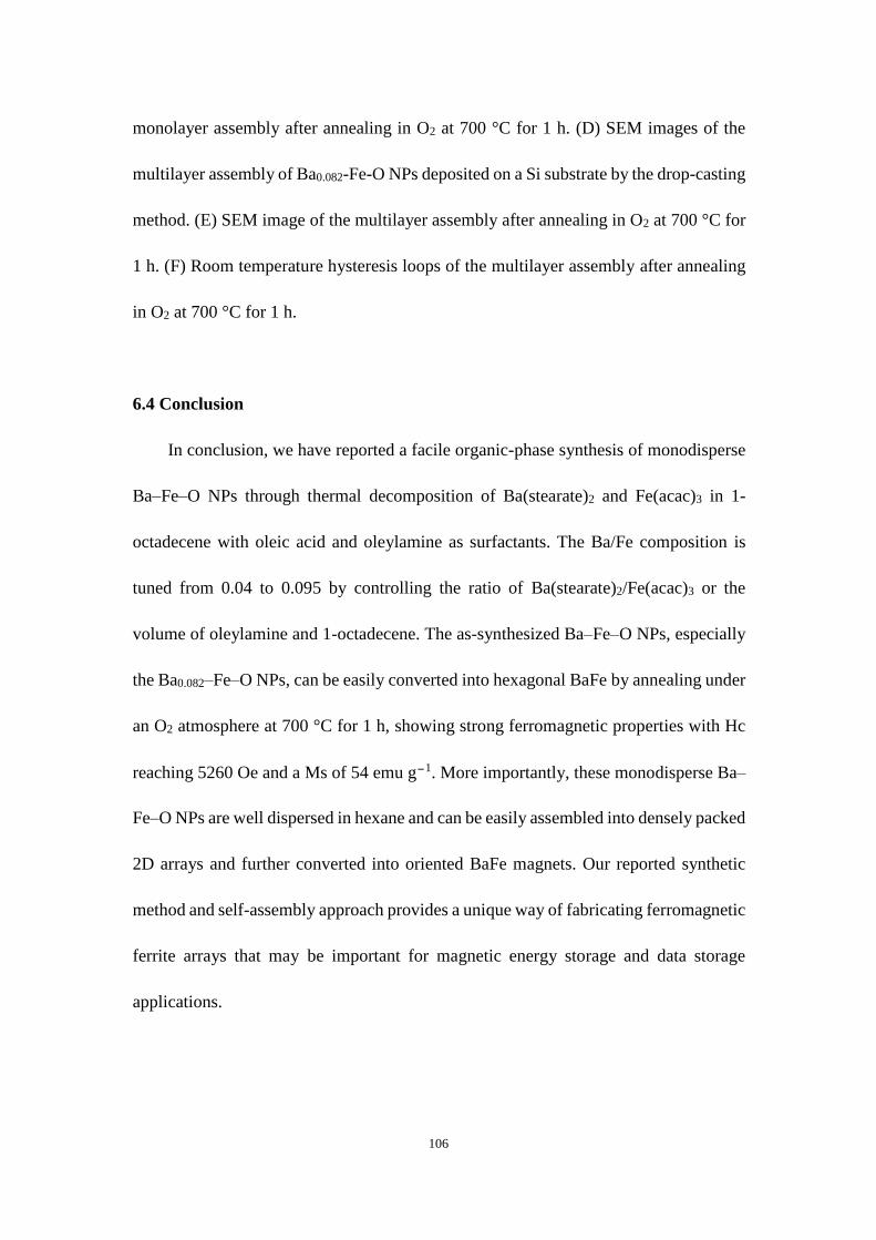
106
monolayer assembly after annealing in O2 at 700 °C for 1 h. (D) SEM images of the
multilayer assembly of Ba0.082-Fe-O NPs deposited on a Si substrate by the drop-casting
method. (E) SEM image of the multilayer assembly after annealing in O2 at 700 °C for
1 h. (F) Room temperature hysteresis loops of the multilayer assembly after annealing
in O2 at 700 °C for 1 h.
6.4 Conclusion
In conclusion, we have reported a facile organic-phase synthesis of monodisperse
Ba–Fe–O NPs through thermal decomposition of Ba(stearate)2 and Fe(acac)3 in 1-
octadecene with oleic acid and oleylamine as surfactants. The Ba/Fe composition is
tuned from 0.04 to 0.095 by controlling the ratio of Ba(stearate)2/Fe(acac)3 or the
volume of oleylamine and 1-octadecene. The as-synthesized Ba–Fe–O NPs, especially
the Ba0.082–Fe–O NPs, can be easily converted into hexagonal BaFe by annealing under
an O2 atmosphere at 700 °C for 1 h, showing strong ferromagnetic properties with Hc
reaching 5260 Oe and a Ms of 54 emu g−1. More importantly, these monodisperse Ba–
Fe–O NPs are well dispersed in hexane and can be easily assembled into densely packed
2D arrays and further converted into oriented BaFe magnets. Our reported synthetic
method and self-assembly approach provides a unique way of fabricating ferromagnetic
ferrite arrays that may be important for magnetic energy storage and data storage
applications.

107
References
1 J. T. Jang, H. Nah, J. H. Lee, S. H. Moon, M. G. Kim and J. Cheon, Angew. Chem.,
Int. Ed., 2009, 48, 1234.
2 W. K. Moon, J. Kim, H. S. Kim, N. Lee, T. Kim, H. Kim, T. Yu, I. C. Song and T.
Hyeon, Angew. Chem., Int. Ed., 2008, 47, 8438.
3 K. Cheng, S. Peng, C. J. Xu and S. H. Sun, J. Am. Chem. Soc., 2009, 131, 10637.
4 T. Hyeon, J. E. Lee, N. Lee, H. Kim, J. Kim, S. H. Choi, J. H. Kim, T. Kim, I. C.
Song, S. P. Park and W. K. Moon, J. Am. Chem. Soc., 2010, 132, 552.
5 J. H. Lee, Y. M. Huh, Y. Jun, J. Seo, J. Jang, H. T. Song, S. Kim, E. J. Cho, H. G.
Yoon, J. S. Suh and J. Cheon, Nat. Med., 2007, 13, 95.
6 J. H. Lee, J. T. Jang, J. S. Choi, S. H. Moon, S. H. Noh, J. W. Kim, J. G. Kim, I. S.
Kim, K. I. Park and J. Cheon, Nat. Nanotechnol., 2011, 6, 418.
7 C. Xu, J. Xie, D. Ho, C. Wang, N. Kohler, E. G. Walsh, J. R. Morgan, Y. E. Chin and
S. Sun, Angew. Chem., Int. Ed., 2008, 47, 173.
8 C. J. Xu, B. D. Wang and S. H. Sun, J. Am. Chem. Soc., 2009, 131, 4216.
9 N. Poudyal and J. P. Liu, J. Phys. D: Appl. Phys., 2013, 46.
10 J. Park, Y. K. Hong, S. G. Kim, S. Kim, L. S. I. Liyanage, J. Lee, W. Lee, G. S. Abo,
K. H. Hur and S. Y. An, J. Magn. Magn. Mater., 2014, 355, 1.
11 R. C. Pullar, Prog. Mater. Sci., 2012, 57, 1191.
12 Q. Dai, D. Berman, K. Virwani, J. Frommer, P. O. Jubert, M. Lam, T. Topuria, W.
Imaino and A. Nelson, Nano Lett., 2010, 10, 3216.
13 L. Wu, P. O. Jubert, D. Berman, W. Imaino, A. Nelson, H. Zhu, S. Zhang and S.

108
Sun, Nano Lett., 2014, 14, 3395.
14 Z. V. Golubenko, L. P. Ol’khovik, Y. A. Popkov, Z. I. Sizova and A. S. Kamzin,
Phys. Solid State, 1998, 40, 1718.
15 J. Wang, F. Zhao, W. Wu and G. M. Zhao, J. Appl. Phys., 2011, 110, 096107.
16 D. Berman, R. Biskeborn, N. Bui, E. Childers, R. D. Cideciyan, W. Dyer, E.
Eleftheriou, D. Hellman, R. Hutchins, W. Imaino, G. Jaquette, J. Jelitto, P. O. Jubert,
C. Lo, G. McClelland, S. Narayan, S. Oelcer, T. Topuria, T. Harasawa, A. Hashimoto,
T. Nagata, H. Ohtsu and S. Saito, IEEE Trans. Magn., 2007, 43, 3502.
17 T. Harasawa, R. Suzuki, O. Shimizu, S. Olcer and E. Eleftheriou, IEEE Trans. Magn.,
2010, 46, 1894.
18 P. O. Jubert, B. Biskeborn, D. N. Qiu, A. Matsumoto, H. Noguchi and O. Shimizu,
IEEE Trans. Magn., 2011, 47, 386.
19 G. Cherubini, R. D. Cideciyan, L. Dellmann, E. Eleftheriou, W. Haeberle, J. Jelitto,
V. Kartik, M. A. Lantz, S. Olcer, A. Pantazi, H. E. Rothuizen, D. Berman, W. Imaino,
P. O. Jubert, G. McClelland, P. V. Koeppe, K. Tsuruta, T. Harasawa, Y. Murata, A.
Musha, H. Noguchi, H. Ohtsu, O. Shimizu and R. Suzuki, IEEE Trans. Magn., 2011,
47, 137.
20 S. Furrer, M. A. Lantz, J. B. C. Engelen, A. Pantazi, H. E. Rothuizen, R. D. Cideciyan,
G. Cherubini, W. Haeberle, J. Jelitto, E. Eleftheriou, M. Oyanagi, Y. Kurihashi, T.
Ishioroshi, T. Kaneko, H. Suzuki, T. Harasawa, O. Shimizu, H. Ohtsu and H. Noguchi,
IEEE Trans. Magn., 2015, 51, 3100207.
21 W. Zhong, W. P. Ding, Y. M. Jiang, N. Zhang, J. R. Zhang, Y. W. Du and Q. J. Yan,

109
J. Am. Ceram. Soc., 1997, 80, 3258.
22 L. Affleck, M. D. Aguas, Q. A. Pankhurst, I. P. Parkin and W. A. Steer, Adv. Mater.,
2000, 12, 1359.
23 J. Jin, S. Ohkoshi and K. Hashimoto, Adv. Mater., 2004, 16, 48.
24 L. C. Li, K. Y. Chen, H. Liu, G. X. Tong, H. S. Qian and B. Hao, J. Alloys Compd.,
2013, 557, 11.
25 A. Yourdkhani, D. Caruntu, A. K. Perez and G. Caruntu, J. Phys. Chem. C, 2014,
118, 1774.
26 P. Xu, X. J. Han and M. J. Wang, J. Phys. Chem. C, 2007, 111, 5866.
27 J. Zhang, J. Fu, F. Li, E. Xie, D. Xue, N. J. Mellors and Y. Peng, ACS Nano, 2012,
6, 2273.
28 M. Manikandan and C. Venkateswaran, J. Magn. Magn. Mater., 2014, 358, 82.
29 D. Lisjak and S. Ovtar, J. Phys. Chem. B, 2013, 117, 1644.
30 D. Primc and D. Makovec, Nanoscale, 2015, 7, 2688.
31 D. Primc, D. Makovec, D. Lisjak and M. Drofenik, Nanotechnology, 2009, 20,
315605.


![Magnetic State of Multilayered Synthetic Antiferromagnets ...eprints.gla.ac.uk/185178/1/185178.pdf(NML). [ 2 ] The core idea of NML consists of using chains of cou-pled nanomagnets](https://img.pdfslide.net/doc/110x75/60dfecd739f1f51a4d2a10bd/magnetic-state-of-multilayered-synthetic-antiferromagnets-nml-2-the-core.jpg)