Embed Size (px)
DESCRIPTION
Technical details of HVAC system of the Toyota Rav4.
Citation preview
BODY ELECTRICAL - AIR CONDITIONING
01MBE08Y
A/C Switch
Blower Switch
A/C Pressure Sensor
Evaporator Temp.Sensor
Air ConditioningECU
CAN
ECM
Engine CoolantTemp. Sensor
Combination Meter
Ambient Temp. Sensor
A/C Compressor� Solenoid Control Valve
BE-20
�SYSTEM DIAGRAM
� Manual Air Conditioning �
BODY ELECTRICAL - AIR CONDITIONING
01MBE07Y
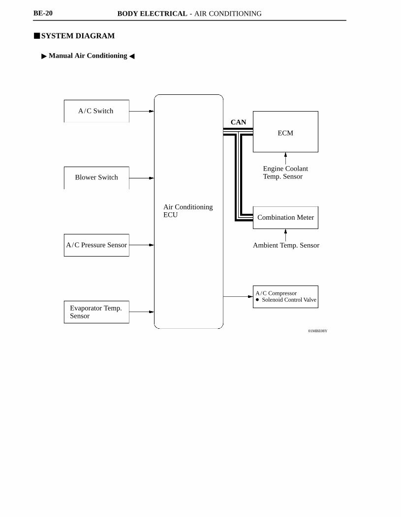
Local Communication
Heater ControlPanel Assembly
Blower Motor Module
A/C Pressure Sensor
Evaporator Temp.Sensor
Solar Sensor
Room Temp.Sensor
Air ConditioningECU
CANECM
Engine Coolant Temp. Sensor
Combination Meter
Ambient Temp. Sensor
Air Mix Servomotor(Driver Side)
Air Mix Servomotor(Front Passenger Side)
Air Inlet Servomotor
Air Vent Servomotor
A/C Compressor� Solenoid Control Valve
Rear Defogger
BE-21
� Automatic Air Conditioning �
BODY ELECTRICAL - AIR CONDITIONING
01NBE30Y
01MBE17Y
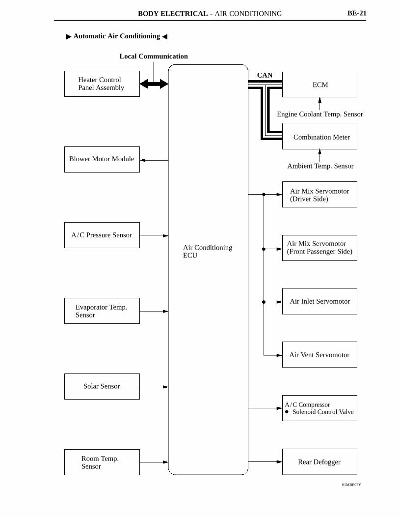
A/C PressureSensor
A/C Compressor� Solenoid Control Valve
Condenser Ambient Temp. Sensor
ECM
With Air Conditioning Models
Solar Sensor*Combination Meter
Heater ControlPanel
Room Temp. Sensor*
Air ConditioningECU
DLC3
BE-22
�LAYOUT OF MAIN COMPONENTS
*: Only for Models with Automatic Air Conditioning
BODY ELECTRICAL - AIR CONDITIONING
01NBE19Y
01NBE20Y
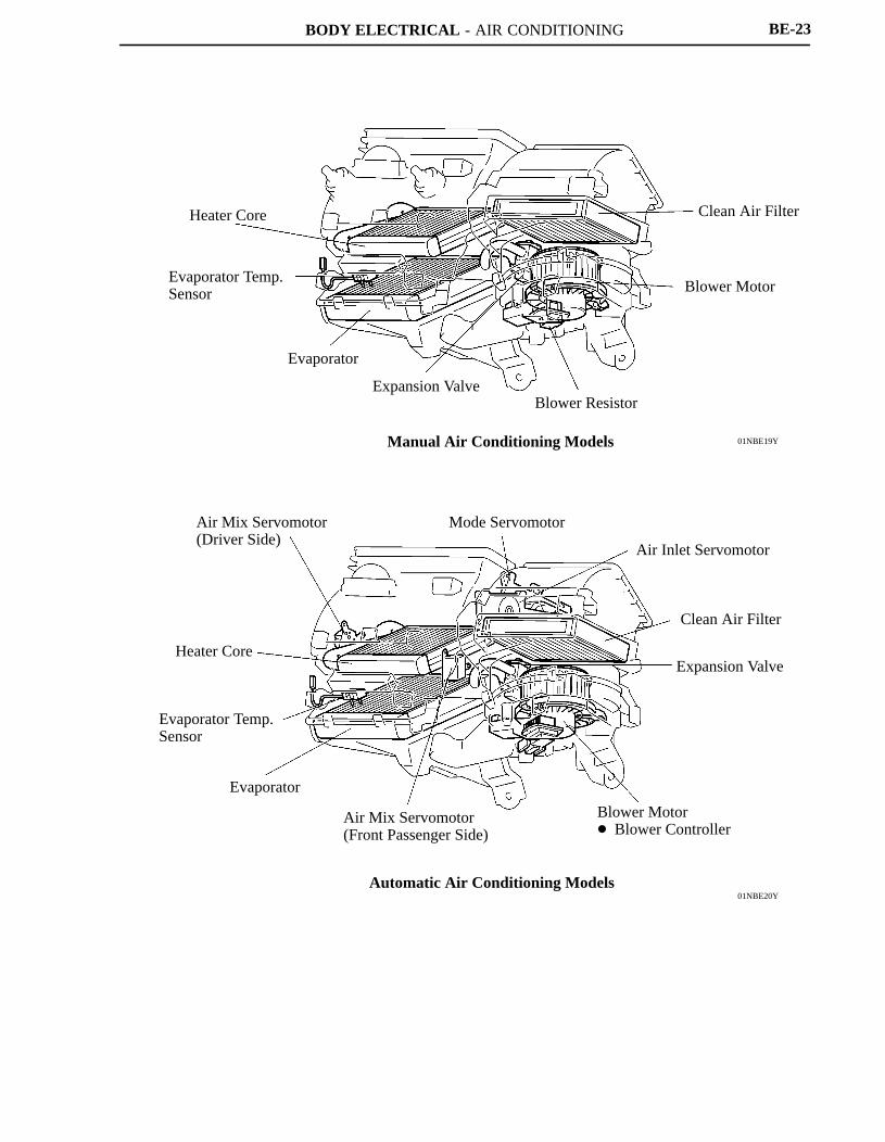
Heater Core
Evaporator Temp.Sensor
Evaporator
Expansion ValveBlower Resistor
Blower Motor
Clean Air Filter
Manual Air Conditioning Models
Air Mix Servomotor(Driver Side)
Heater Core
Evaporator Temp.Sensor
Evaporator
Air Mix Servomotor(Front Passenger Side)
Blower Motor� Blower Controller
Expansion Valve
Clean Air Filter
Air Inlet Servomotor
Mode Servomotor
Automatic Air Conditioning Models
BE-23
BODY ELECTRICAL - AIR CONDITIONING
01NBE78Y
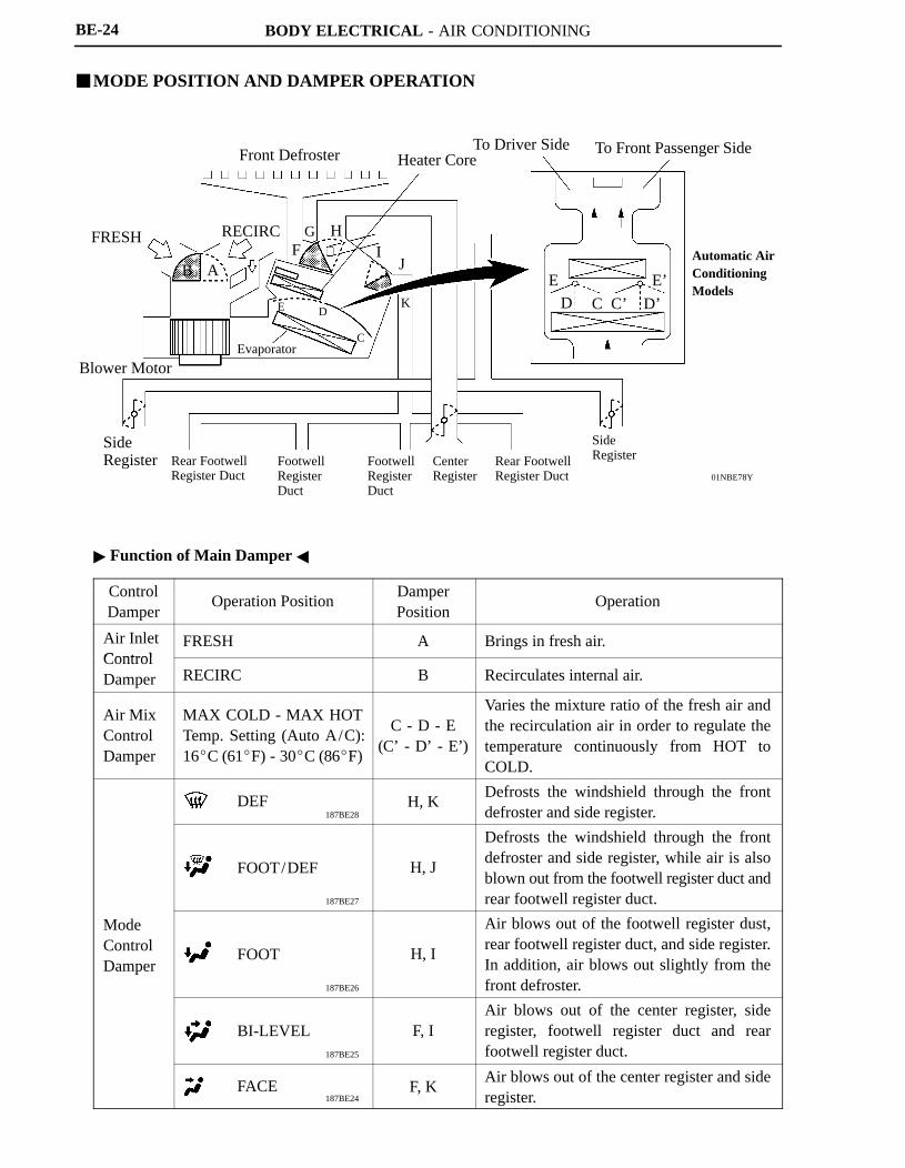
Front Defroster Heater CoreTo Driver Side To Front Passenger Side
FRESH
B AF
G HI
J
KE D
CEvaporator
Blower Motor
SideRegister Rear Footwell
Register DuctFootwellRegisterDuct
FootwellRegisterDuct
CenterRegister
Rear FootwellRegister Duct
SideRegister
ED C C’ D’
E’
Automatic AirConditioningModels
RECIRC
187BE28
187BE27
187BE26
187BE25
187BE24
DEF
FOOT/DEF
FOOT
BI-LEVEL
FACE
BE-24
�MODE POSITION AND DAMPER OPERATION
� Function of Main Damper �
ControlDamper
Operation PositionDamperPosition
Operation
Air InletControl
FRESH A Brings in fresh air.ControlDamper RECIRC B Recirculates internal air.
Air MixControlDamper
MAX COLD - MAX HOTTemp. Setting (Auto A/C):16�C (61�F) - 30�C (86�F)
C - D - E(C’ - D’ - E’)
Varies the mixture ratio of the fresh air andthe recirculation air in order to regulate thetemperature continuously from HOT toCOLD.
H, KDefrosts the windshield through the frontdefroster and side register.
H, J
Defrosts the windshield through the frontdefroster and side register, while air is alsoblown out from the footwell register duct andrear footwell register duct.
ModeControlDamper
H, I
Air blows out of the footwell register dust,rear footwell register duct, and side register.In addition, air blows out slightly from thefront defroster.
F, IAir blows out of the center register, sideregister, footwell register duct and rearfootwell register duct.
F, KAir blows out of the center register and sideregister.
BODY ELECTRICAL - AIR CONDITIONING
01MMO36Y
BE-25
�CONSTRUCTION AND OPERATION
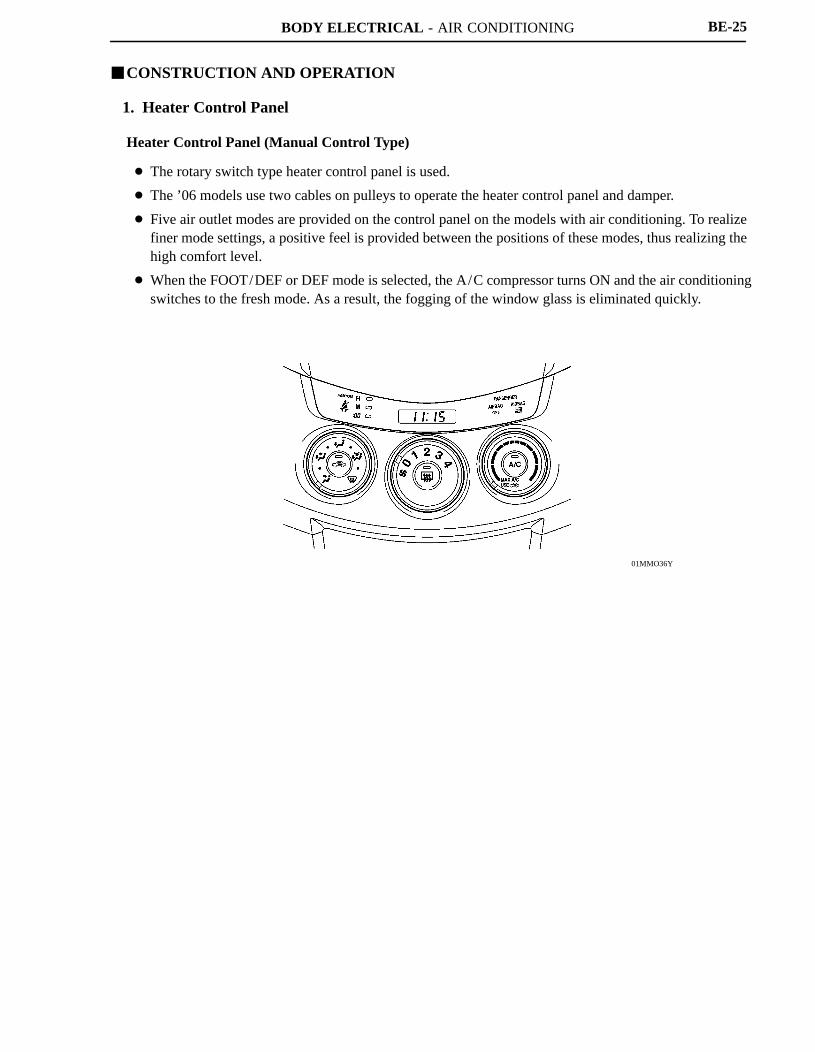
1. Heater Control Panel
Heater Control Panel (Manual Control Type)
� The rotary switch type heater control panel is used.
� The ’06 models use two cables on pulleys to operate the heater control panel and damper.
� Five air outlet modes are provided on the control panel on the models with air conditioning. To realizefiner mode settings, a positive feel is provided between the positions of these modes, thus realizing thehigh comfort level.
� When the FOOT/DEF or DEF mode is selected, the A/C compressor turns ON and the air conditioningswitches to the fresh mode. As a result, the fogging of the window glass is eliminated quickly.
BODY ELECTRICAL - AIR CONDITIONING
271BE20
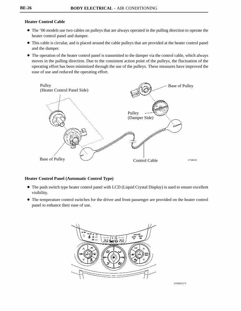
Pulley(Heater Control Panel Side)
Base of Pulley
Pulley(Damper Side)
Control Cable
Base of Pulley
01MMO37Y
BE-26
Heater Control Cable
� The ’06 models use two cables on pulleys that are always operated in the pulling direction to operate theheater control panel and damper.
� This cable is circular, and is placed around the cable pulleys that are provided at the heater control paneland the damper.
� The operation of the heater control panel is transmitted to the damper via the control cable, which alwaysmoves in the pulling direction. Due to the consistent action point of the pulleys, the fluctuation of theoperating effort has been minimized through the use of the pulleys. These measures have improved theease of use and reduced the operating effort.
Heater Control Panel (Automatic Control Type)
� The push switch type heater control panel with LCD (Liquid Crystal Display) is used to ensure excellentvisibility.
� The temperature control switches for the driver and front passenger are provided on the heater controlpanel to enhance their ease of use.
BODY ELECTRICAL - AIR CONDITIONING
01NBE77Y
Front Front
Side View Top View
Heater Core
Evaporator
Heater Core
Evaporator
01NBE29Y
Air Inlet Control Door
FRESHRECIRC
Air Inlet Duct
Air Inlet Control Door (sub)
RECIRC
Blower Fan
BE-27
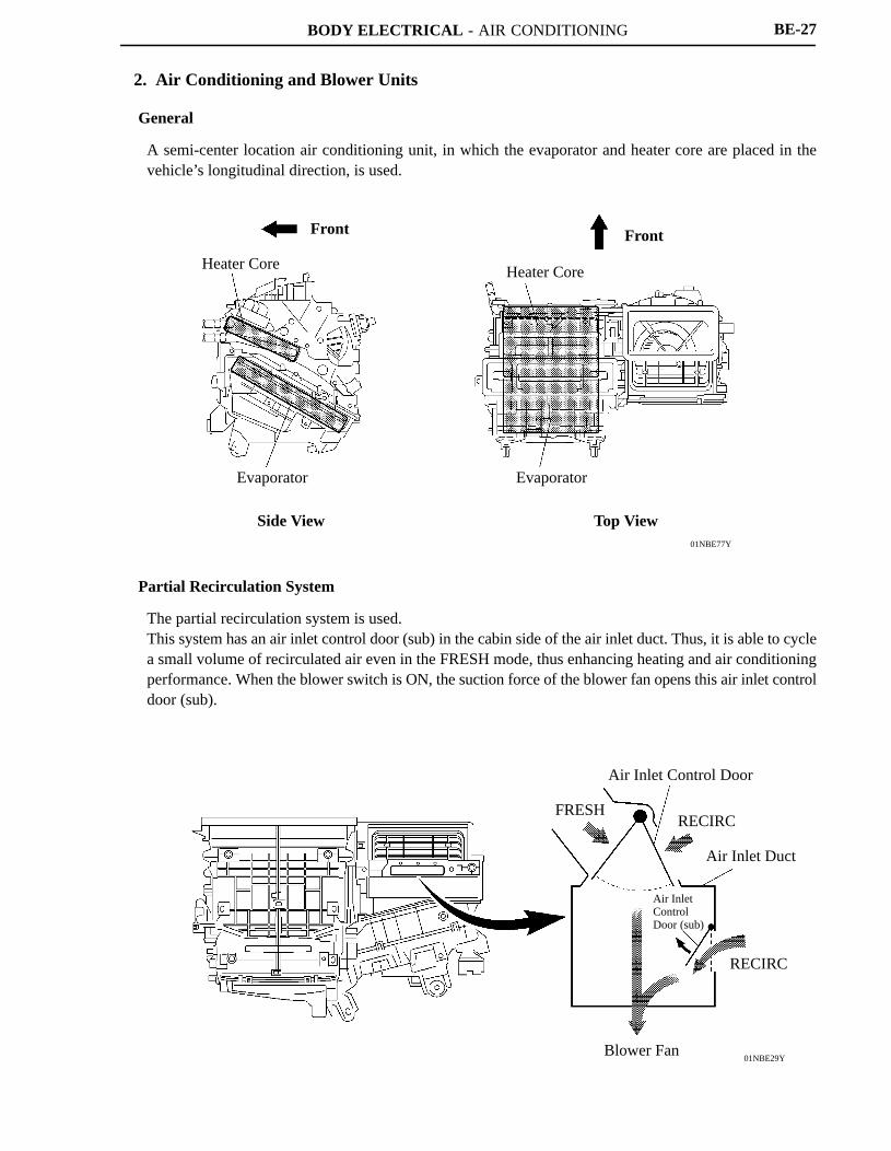
2. Air Conditioning and Blower Units
General
A semi-center location air conditioning unit, in which the evaporator and heater core are placed in thevehicle’s longitudinal direction, is used.
Partial Recirculation System
The partial recirculation system is used.This system has an air inlet control door (sub) in the cabin side of the air inlet duct. Thus, it is able to cyclea small volume of recirculated air even in the FRESH mode, thus enhancing heating and air conditioningperformance. When the blower switch is ON, the suction force of the blower fan opens this air inlet controldoor (sub).
BODY ELECTRICAL - AIR CONDITIONING
271BE66
TankCooling Fin
Micropore Tube
Tank
Antibacterial Agent
Nylon Layer
Chromate-free Layer
Aluminum Matrix
271BE65
OUT
IN
BE-28
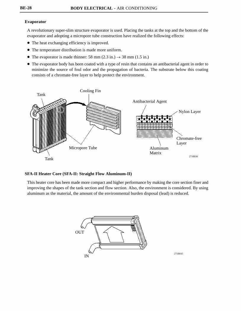
Evaporator
A revolutionary super-slim structure evaporator is used. Placing the tanks at the top and the bottom of theevaporator and adopting a micropore tube construction have realized the following effects:
� The heat exchanging efficiency is improved.
� The temperature distribution is made more uniform.
� The evaporator is made thinner: 58 mm (2.3 in.) � 38 mm (1.5 in.)
� The evaporator body has been coated with a type of resin that contains an antibacterial agent in order tominimize the source of foul odor and the propagation of bacteria. The substrate below this coatingconsists of a chromate-free layer to help protect the environment.
SFA-II Heater Core (SFA-II: Straight Flow Aluminum-II)
This heater core has been made more compact and higher performance by making the core section finer andimproving the shapes of the tank section and flow section. Also, the environment is considered. By usingaluminum as the material, the amount of the environmental burden disposal (lead) is reduced.
BODY ELECTRICAL - AIR CONDITIONING
01NBE27Y
BUS Connector BUS Connector BUS Connector BUS Connector
To Air InletServomotor
To Air VentServomotor
To Air Mix Servomotor(Front Passenger Side) To Air Mix Servomotor
(Driver Side)
To A/C ECU To EvaporatorTemp. Sensor
285BE44
285BE45
A/C ECU
CommunicationIC
CPU
BUS Connector
Communication/Drive IC
Servomotor
With BUS Connector
A/C ECU
CPU
DriveIC
DriveIC
Servomotor
Without BUS Connector
BE-29
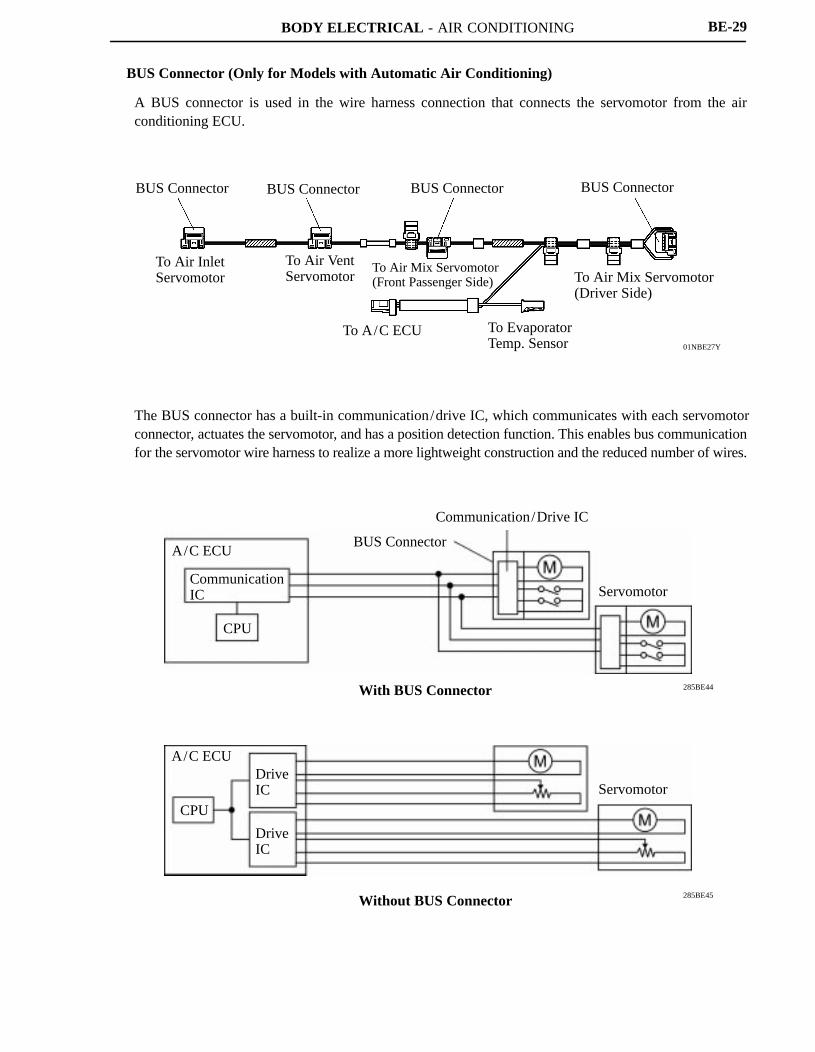
BUS Connector (Only for Models with Automatic Air Conditioning)
A BUS connector is used in the wire harness connection that connects the servomotor from the airconditioning ECU.
The BUS connector has a built-in communication/drive IC, which communicates with each servomotorconnector, actuates the servomotor, and has a position detection function. This enables bus communicationfor the servomotor wire harness to realize a more lightweight construction and the reduced number of wires.
BODY ELECTRICAL - AIR CONDITIONING
281BE126
Rotation Direction of Printed BoardFixed Contact Point Rotation Direction of
Printed Board Printed Board
Pattern (Conductive Part)
Phase A: +
Common: GNDPhase B: +
Pattern No.Phase A
Phase B
1 2 3 4 1 2 3 41 1 0 0 1 1 0 0
Pattern Width 2.81�
Pattern Width
Phase BPhase ACommon
0 1 1 0 0 1 1 0
Pattern Switch
Phase A: +Common: GND
Phase B: +
01NBE76Y
Clean Air Filter
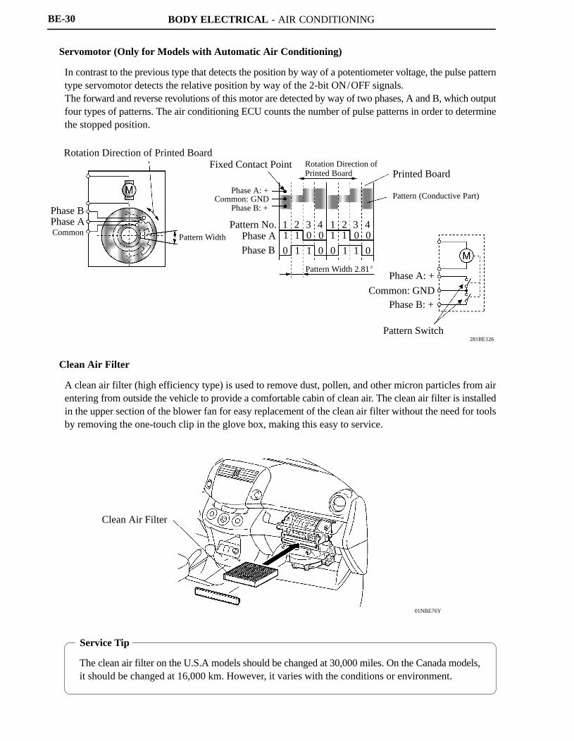
Service Tip
The clean air filter on the U.S.A models should be changed at 30,000 miles. On the Canada models,it should be changed at 16,000 km. However, it varies with the conditions or environment.
BE-30
Servomotor (Only for Models with Automatic Air Conditioning)
In contrast to the previous type that detects the position by way of a potentiometer voltage, the pulse patterntype servomotor detects the relative position by way of the 2-bit ON/OFF signals.The forward and reverse revolutions of this motor are detected by way of two phases, A and B, which outputfour types of patterns. The air conditioning ECU counts the number of pulse patterns in order to determinethe stopped position.
Clean Air Filter
A clean air filter (high efficiency type) is used to remove dust, pollen, and other micron particles from airentering from outside the vehicle to provide a comfortable cabin of clean air. The clean air filter is installedin the upper section of the blower fan for easy replacement of the clean air filter without the need for toolsby removing the one-touch clip in the glove box, making this easy to service.
BODY ELECTRICAL - AIR CONDITIONING
01NBE23Y
Multi-flow Condenser Condensing Portion
Modulator
Desiccant
Filter
Super-cooling Portion
LiquidRefrigerant
GaseousRefrigerant
152BE40
HighPressure
Properly Recharged Amount
Point in which Bubbles Disappear
Amount of Refrigerant
BE-31
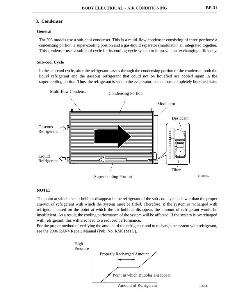
3. Condenser
General
The ’06 models use a sub-cool condenser. This is a multi-flow condenser consisting of three portions: acondensing portion, a super-cooling portion and a gas-liquid separator (modulator) all integrated together.This condenser uses a sub-cool cycle for its cooling cycle system to improve heat-exchanging efficiency.
Sub-cool Cycle
In the sub-cool cycle, after the refrigerant passes through the condensing portion of the condenser, both theliquid refrigerant and the gaseous refrigerant that could not be liquefied are cooled again in thesuper-cooling portion. Thus, the refrigerant is sent to the evaporator in an almost completely liquefied state.
NOTE:
The point at which the air bubbles disappear in the refrigerant of the sub-cool cycle is lower than the properamount of refrigerant with which the system must be filled. Therefore, if the system is recharged withrefrigerant based on the point at which the air bubbles disappear, the amount of refrigerant would beinsufficient. As a result, the cooling performance of the system will be affected. If the system is overchargedwith refrigerant, this will also lead to a reduced performance.For the proper method of verifying the amount of the refrigerant and to recharge the system with refrigerant,see the 2006 RAV4 Repair Manual (Pub. No. RM01M1U).
BODY ELECTRICAL - AIR CONDITIONING
240BE93
Shaft
Crank Chamber
Shoe
Piston
Solenoid ControlValve
Cylinder
Piston
Lug Plate
285BE49
Crank Chamber
Piston
Piston
A/C ECU
SuctionPressure
DischargePressure
Suction
Discharge
Solenoid Control Valve
BE-32
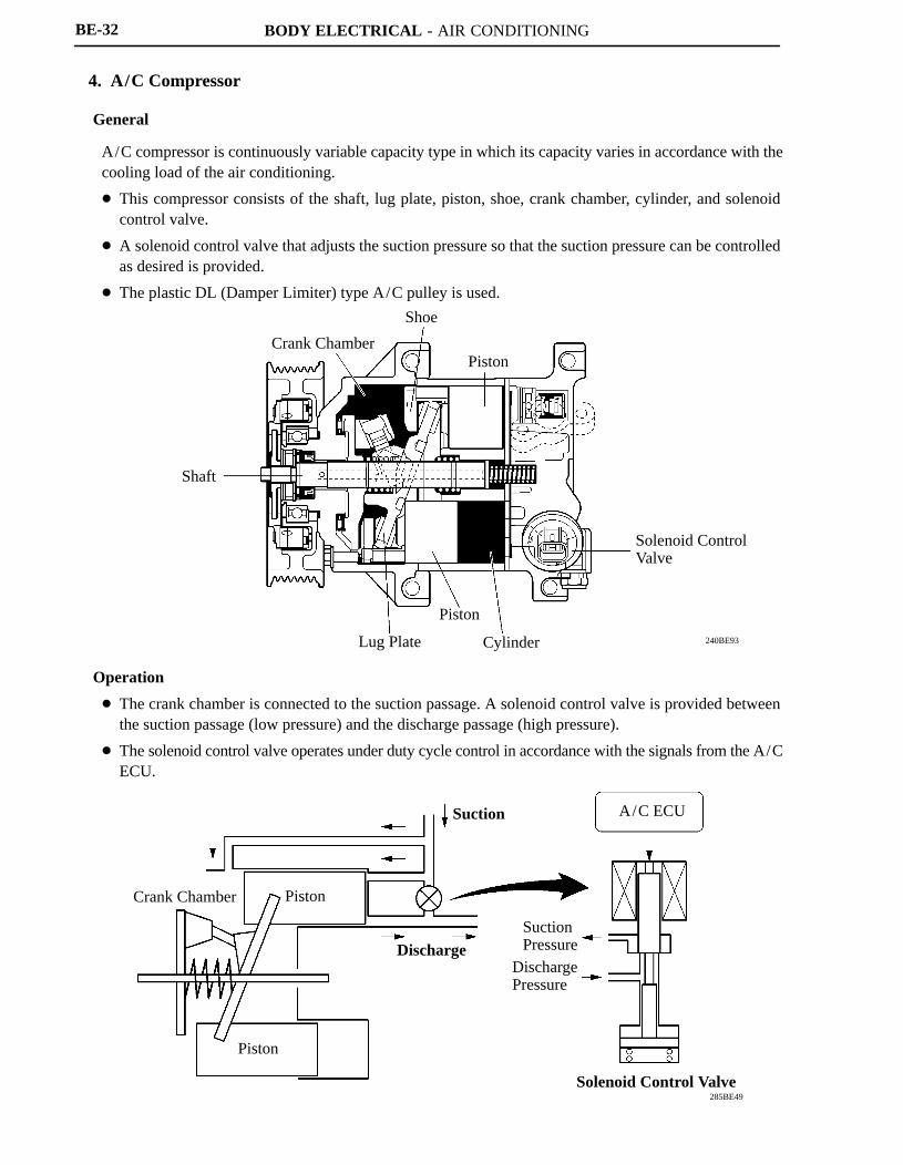
4. A/C Compressor
General
A/C compressor is continuously variable capacity type in which its capacity varies in accordance with thecooling load of the air conditioning.
� This compressor consists of the shaft, lug plate, piston, shoe, crank chamber, cylinder, and solenoidcontrol valve.
� A solenoid control valve that adjusts the suction pressure so that the suction pressure can be controlledas desired is provided.
� The plastic DL (Damper Limiter) type A/C pulley is used.
Operation
� The crank chamber is connected to the suction passage. A solenoid control valve is provided betweenthe suction passage (low pressure) and the discharge passage (high pressure).
� The solenoid control valve operates under duty cycle control in accordance with the signals from the A/CECU.
BODY ELECTRICAL - AIR CONDITIONING
285BE50
Crank ChamberPressure + SpringForce
Piston Stroke: Large
A/C ECU
DischargePressure
Suction
Discharge
Solenoid Control Valve
285BE51
A/C ECU
Suction Pressure
DischargePressure
Crank ChamberPressure + SpringForce
Piston Stroke: Small
Suction
Discharge
Solenoid Control Valve
BE-33
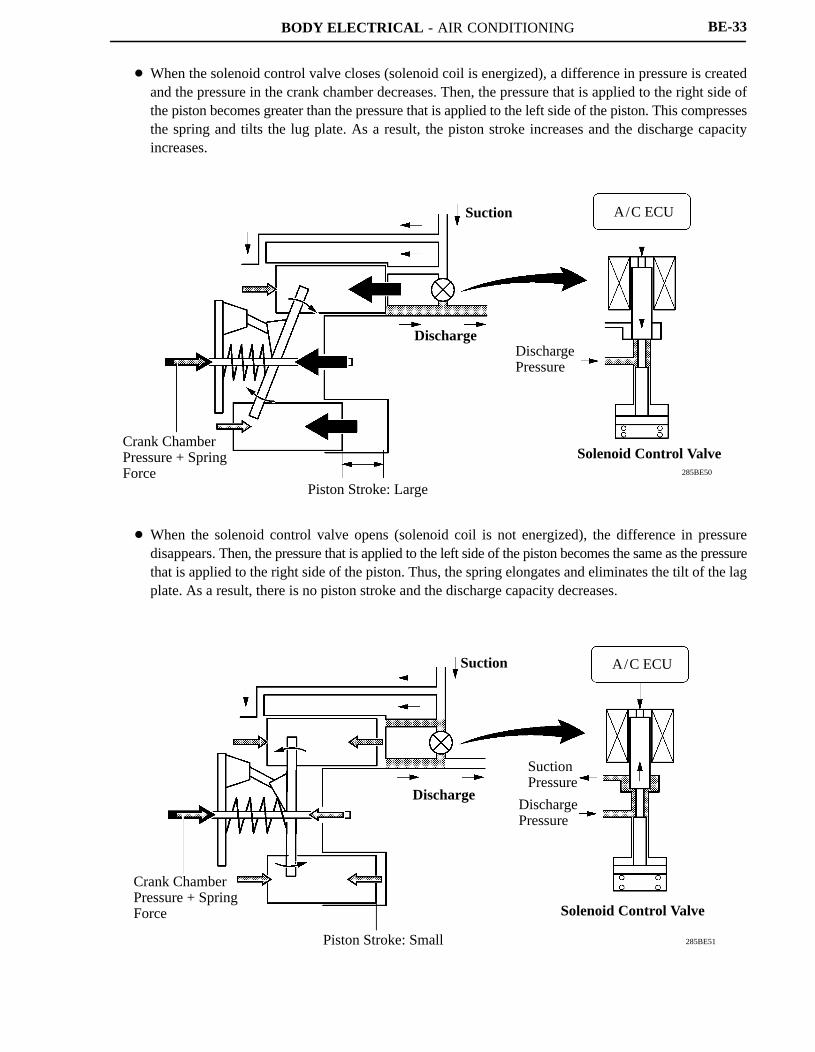
� When the solenoid control valve closes (solenoid coil is energized), a difference in pressure is createdand the pressure in the crank chamber decreases. Then, the pressure that is applied to the right side ofthe piston becomes greater than the pressure that is applied to the left side of the piston. This compressesthe spring and tilts the lug plate. As a result, the piston stroke increases and the discharge capacityincreases.
� When the solenoid control valve opens (solenoid coil is not energized), the difference in pressuredisappears. Then, the pressure that is applied to the left side of the piston becomes the same as the pressurethat is applied to the right side of the piston. Thus, the spring elongates and eliminates the tilt of the lagplate. As a result, there is no piston stroke and the discharge capacity decreases.
BODY ELECTRICAL - AIR CONDITIONING
240BE92
Spoke Portions
Rotate Direction
Pulley Portion (Plastic)
Damper
Damper
Limiter Mechanism
BE-34
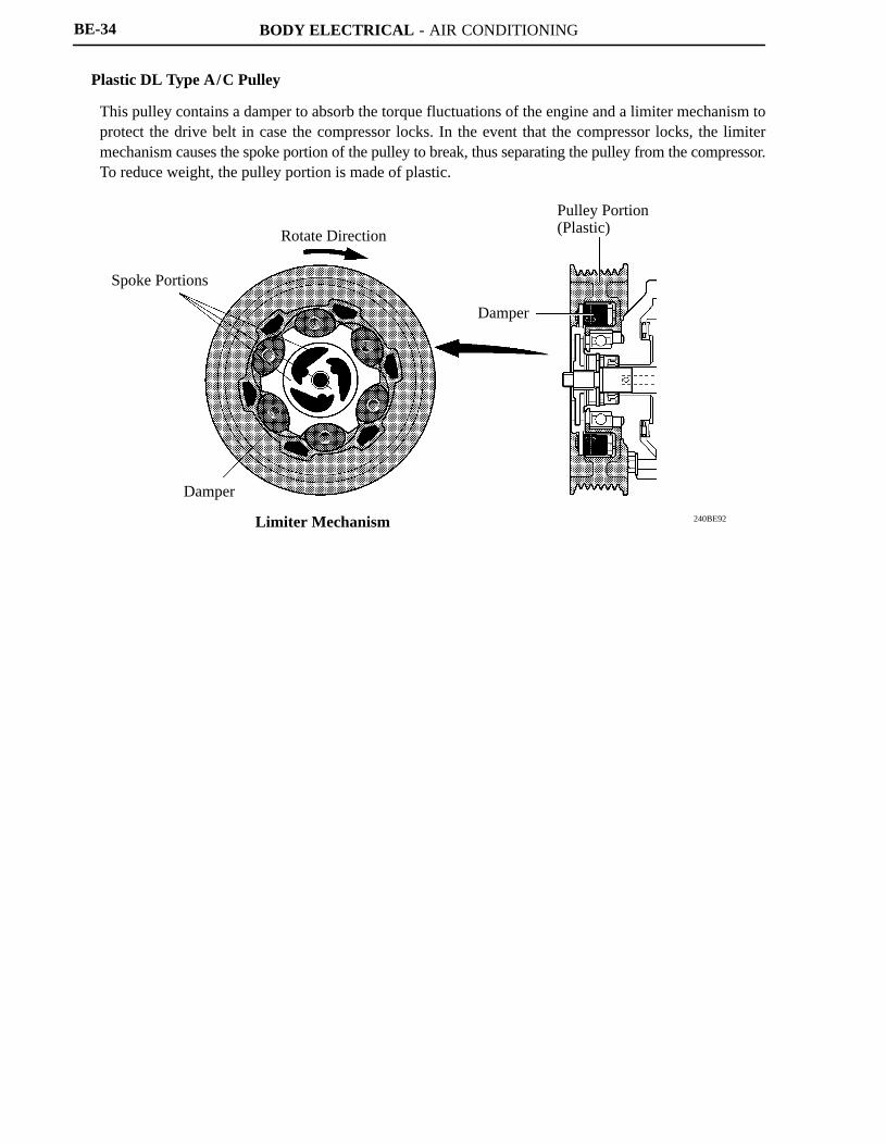
Plastic DL Type A/C Pulley
This pulley contains a damper to absorb the torque fluctuations of the engine and a limiter mechanism toprotect the drive belt in case the compressor locks. In the event that the compressor locks, the limitermechanism causes the spoke portion of the pulley to break, thus separating the pulley from the compressor.To reduce weight, the pulley portion is made of plastic.
BODY ELECTRICAL - AIR CONDITIONING BE-35
�AIR CONDITIONING CONTROL
1. Air Conditioning ECU
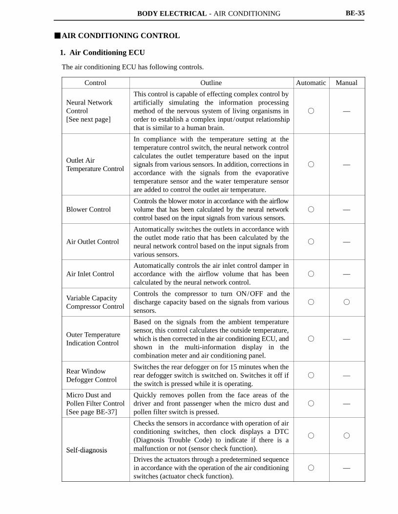
The air conditioning ECU has following controls.
Control Outline Automatic Manual
Neural Network Control [See next page]
This control is capable of effecting complex control byartificially simulating the information processingmethod of the nervous system of living organisms inorder to establish a complex input/output relationshipthat is similar to a human brain.
� —
Outlet Air Temperature Control
In compliance with the temperature setting at thetemperature control switch, the neural network controlcalculates the outlet temperature based on the inputsignals from various sensors. In addition, corrections inaccordance with the signals from the evaporativetemperature sensor and the water temperature sensorare added to control the outlet air temperature.
� —
Blower ControlControls the blower motor in accordance with the airflowvolume that has been calculated by the neural networkcontrol based on the input signals from various sensors.
� —
Air Outlet Control
Automatically switches the outlets in accordance withthe outlet mode ratio that has been calculated by theneural network control based on the input signals fromvarious sensors.
� —
Air Inlet ControlAutomatically controls the air inlet control damper inaccordance with the airflow volume that has beencalculated by the neural network control.
� —
Variable Capacity Compressor Control
Controls the compressor to turn ON/OFF and thedischarge capacity based on the signals from varioussensors.
� �
Outer TemperatureIndication Control
Based on the signals from the ambient temperaturesensor, this control calculates the outside temperature,which is then corrected in the air conditioning ECU, andshown in the multi-information display in thecombination meter and air conditioning panel.
� —
Rear Window Defogger Control
Switches the rear defogger on for 15 minutes when therear defogger switch is switched on. Switches it off ifthe switch is pressed while it is operating.
� —
Micro Dust and Pollen Filter Control[See page BE-37]
Quickly removes pollen from the face areas of thedriver and front passenger when the micro dust andpollen filter switch is pressed.
� —
Self-diagnosis
Checks the sensors in accordance with operation of airconditioning switches, then clock displays a DTC(Diagnosis Trouble Code) to indicate if there is amalfunction or not (sensor check function).
� �
Self diagnosisDrives the actuators through a predetermined sequencein accordance with the operation of the air conditioningswitches (actuator check function).
� —
BODY ELECTRICAL - AIR CONDITIONING
189BE109
Input Processing
Temp. Setting
Sensor Input
Switch Input
Control
NeuralNetworking
Target OutletTemp.
Amount ofSunlight Correction
Target AirflowVolume
Outlet Mode
Inlet Mode
Compressor
Temp. ControlCorrection
Various Types ofAirflow VolumeCorrections
Various Typesof ModeCorrections
Various Typesof Corrections
OutputProcessing
Air Mix ControlDamper
Blower Motor
Mode ControlDamper
Air Inlet ControlDamper
Compressor
Intermediate Layer
Input LayerAmbientTemp.
Amount ofSunlight
Room Temp.
Target OutputTemp.
Output Layer
: Neural Network Operation Range
BE-36
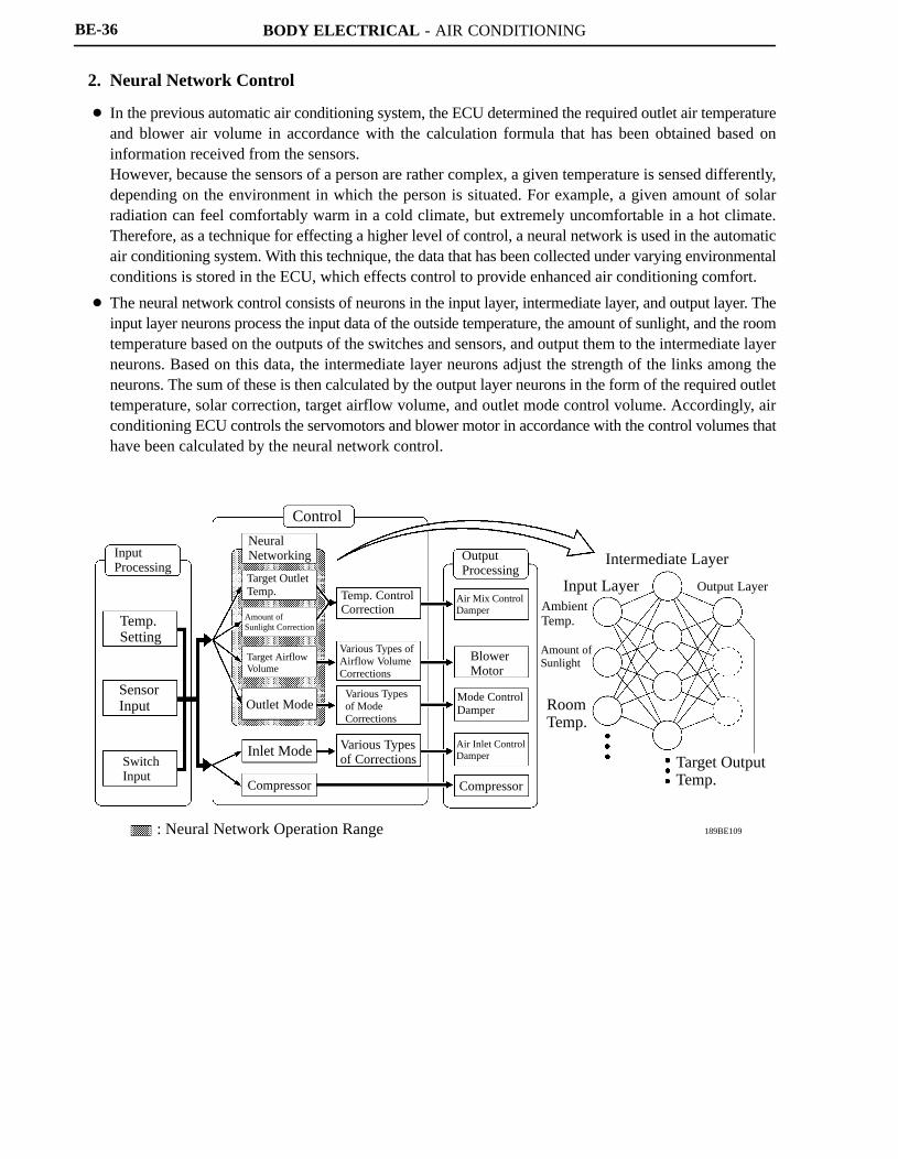
2. Neural Network Control
� In the previous automatic air conditioning system, the ECU determined the required outlet air temperatureand blower air volume in accordance with the calculation formula that has been obtained based oninformation received from the sensors.However, because the sensors of a person are rather complex, a given temperature is sensed differently,depending on the environment in which the person is situated. For example, a given amount of solarradiation can feel comfortably warm in a cold climate, but extremely uncomfortable in a hot climate.Therefore, as a technique for effecting a higher level of control, a neural network is used in the automaticair conditioning system. With this technique, the data that has been collected under varying environmentalconditions is stored in the ECU, which effects control to provide enhanced air conditioning comfort.
� The neural network control consists of neurons in the input layer, intermediate layer, and output layer. Theinput layer neurons process the input data of the outside temperature, the amount of sunlight, and the roomtemperature based on the outputs of the switches and sensors, and output them to the intermediate layerneurons. Based on this data, the intermediate layer neurons adjust the strength of the links among theneurons. The sum of these is then calculated by the output layer neurons in the form of the required outlettemperature, solar correction, target airflow volume, and outlet mode control volume. Accordingly, airconditioning ECU controls the servomotors and blower motor in accordance with the control volumes thathave been calculated by the neural network control.
BODY ELECTRICAL - AIR CONDITIONING
01NBE02Y
Air Inlet ControlDamper
Mode ControlDamper
Blower MotorLevel
RECIRCFRESH
FACEBI-LEVEL
FOOTHIGH
M2M1
LOWOFF
Micro Dust and Pollen Filter Mode Normal Automatic Mode
0 1 2 3 Time (Min.)
: In micro dust and pollen filter mode: In normal automatic mode
BE-37
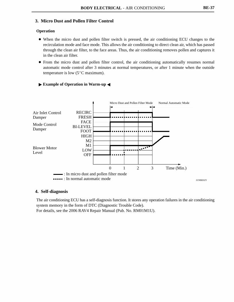
3. Micro Dust and Pollen Filter Control
Operation
� When the micro dust and pollen filter switch is pressed, the air conditioning ECU changes to therecirculation mode and face mode. This allows the air conditioning to direct clean air, which has passedthrough the clean air filter, to the face areas. Thus, the air conditioning removes pollen and captures itin the clean air filter.
� From the micro dust and pollen filter control, the air conditioning automatically resumes normalautomatic mode control after 3 minutes at normal temperatures, or after 1 minute when the outsidetemperature is low (5�C maximum).
� Example of Operation in Warm-up �
4. Self-diagnosis
The air conditioning ECU has a self-diagnosis function. It stores any operation failures in the air conditioningsystem memory in the form of DTC (Diagnostic Trouble Code).For details, see the 2006 RAV4 Repair Manual (Pub. No. RM01M1U).